Datto DNWAP62 WiFi Access Point User Manual QSG AP62
Datto, Inc. WiFi Access Point Users Manual QSG AP62
Datto >
Contents
Users Manual-QSG-AP62
For more information, visit www.datto.com/networking
© 2017 Datto Inc. All rights reserved.
Outdoor Mount
This access point can be congured as an outdoor model and
mounted to any wall or pole. This conguration protects against
the sun, rain and dust. Operating temperatures for this access
point range from 0°C to 50°C.
Ethernet or Junction Box Mount
This access point can be mounted to any junction box for secure
installations in hotel and resort guest rooms, dorms, care facilities
and more.
AP62
Quick Start Guide
Additional Resources
Datto’s Partner Portal (partners.datto.com) is the place to go for
everything Datto. The Partner Portal includes:
• Datto Knowledge Base (kb.datto.com) - technical articles to
help you with all of your Datto Networking needs
• MarketNow (datto.com/marketnow) - your very own Marketing
Automation Platform
• Sales Resources - Sales Playbooks, MSPeasy eBooks and
videos, etc.
Your dedicated Channel Account Manager can help with sales and
planning questions along the way. If you need additional help, the
Datto Support Team is here for you 24/7/365.
Contact Us
support@datto.com
North America: +1.877.455.6015
EMEA: +44.(0).118.402.9609
Australia/New Zealand: +61 (02) 8015 6826
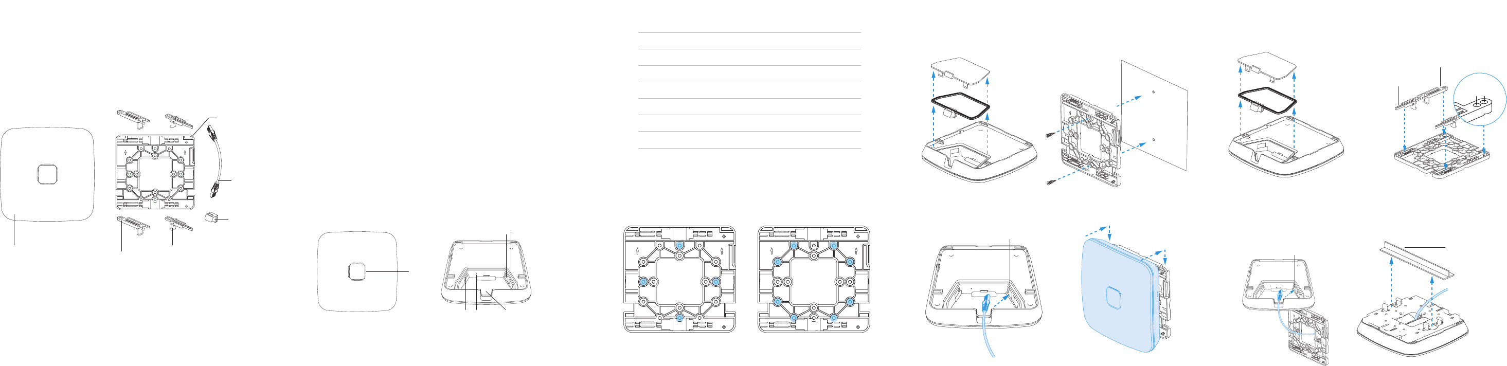
1) Remove rear door and seal. 2) Mount at side of plate to
junction box.
4) Slide device down plate to
lock in place.
3) Connect included slim
ethernet cable from device
(Port 1) to connection in wall.
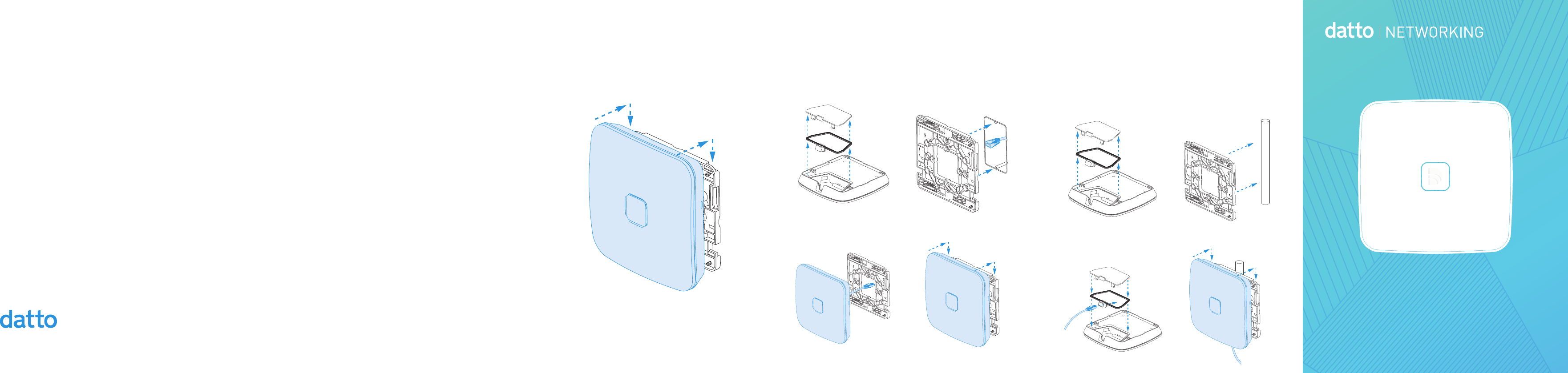
1) Remove rear door and seal.
Peel plastic tab off from door.
2) Secure at side of mount to
outdoor xture. Arrows on plate
pointing upwards.
3) Place ethernet cable
through seal and connect to
device (Port 1). Reinstall seal
and back cover.
4) Slide device down plate to
lock in place.
Unmounting Directions
To unlock, insert a small, at screwdriver into the Mount Release
Hole on the side of the access point. Slide the access point
upwards until it disengages from the mounting plate.
Mounting Bracket Overview
T-Rail Ceiling Mount
For attaching to drop ceiling T-Rail or other T-Rail System.
LED indicator
Ethernet Port1,
802.3af PoE(48-54V=0.6A)
Reset Button Cable ChannelUSB 2.0
Ethernet Por2,
passive PoE(18-24V=1.34-1A)
Physical Installation
This access point is designed to be installed indoors or out, in
several mounting positions. Regardless of how you mount this
access point, keep the following in mind:
• 802.3af PoE input is required. Connect to any Datto Networking
Switch, an 802.3af-compatible PoE switch or PoE injector.
• Place in the center of the room and away from any metallic
surfaces.
• Signal primarily radiates to the front and sides. There is limited
signal coverage directly behind it.
• Do not place heavy objects on the access point.
• Install in an area free from strong electromagnetic sources.
• Check the Ethernet cables to ensure they are fully secured to
both the access point and PoE injector or switch.
• Do not install this access point in plenum spaces. Use the
ceiling mount instead.
US single
gang box
US dual
gang box
Wall or Solid Ceiling Mount
Attach the universal mounting plate to any solid surface
(screws are not included).
STATE LIGHT COLOR
Online, Mesh Speed >2Mbps Solid Blue
Online, Mesh Speed <=2Mbps Flash Blue
Boot Loader Solid Purple
Booting Up Solid Yellow
Firmware Upgrade Solid Red
CloudTrax Checkin Failure Flash White
Key Re-pair Flash Yellow
Conguration Change AP not ready Solid White
Net Failure - no default route Flash Red
Access Point Overview
LED Light States
1) Remove rear door and seal. 2) Mount at side of plate to
wall or ceiling.
3) Connect ethernet cable to
device (Port 1).
4) Slide device down plate to lock
in place.
2) Place all four T-Rail clips into
mounting plate.
3) Place ethernet through
mount and connect ethernet
to device (Port 1). Slide mount
onto device.
4) Use the adjustable rail clips
to tighten to the ceiling T-Rail
until secure.
What’s in the Box
(1) Access Point
(4) T-Rail Clips (ceiling rail mount)
(1) Slim Ethernet Cable (for wall or junction box mount)
(1) Mounting Plate
(1) Ethernet Hole Cover
Cloud Management
1. Sign in to networking.datto.com. Click Add New button.
2. Create a new network by navigating to All Networks > Create
Network, or select an existing network on the All Networks page.
3. On the left menu, navigate to Access Points. Click Add New
and enter the MAC address. Use the drop-down arrow to enter
multiple MAC addresses at once or upload a CSV file.
Repeat this process to add as many access points as required.
4. Connect device to internet over ethernet or an existing Datto
mesh network. The device will then configure and start reporting
status within a few minutes.
Note: Ethernet port 1 is PoE input. The pass-through port (Ethernet 2) is data only.
No power is passed through the second port.
Smaller, Adjustable T-Rail
Larger, Fixed T-Rail
Access Point
Slim
Ethernet Cable
Ethernet
Hole Cover
Mounting Plate
Ethernet port 1, 802.3af PoE
1) Remove rear door and seal. 1) Remove rear door and seal.
15/16" rails 9/16" rails
Smaller, Adjustable T-Rail
Larger, Fixed T-Rail
T-Rail (not included)
Ethernet port 1, 802.3af PoE