Datto OM2PLC Wireless 802.11b/g/n Mesh Router User Manual OM2P UM for FCC apply
Open Mesh, Inc. Wireless 802.11b/g/n Mesh Router OM2P UM for FCC apply
UserManual.wiki
>
Datto
>
OM2PLC User Manual
User Manual
Navigation menu
Upload a User Manual
Namespaces
Wiki Guide
HTML
PDF
Info
Views
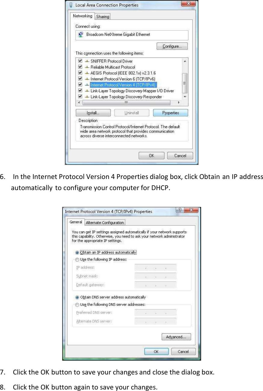
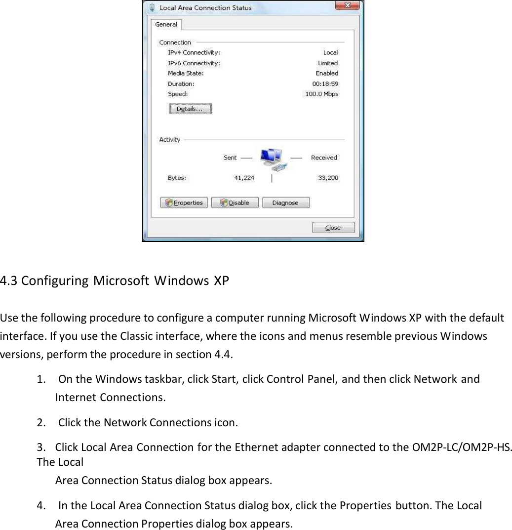
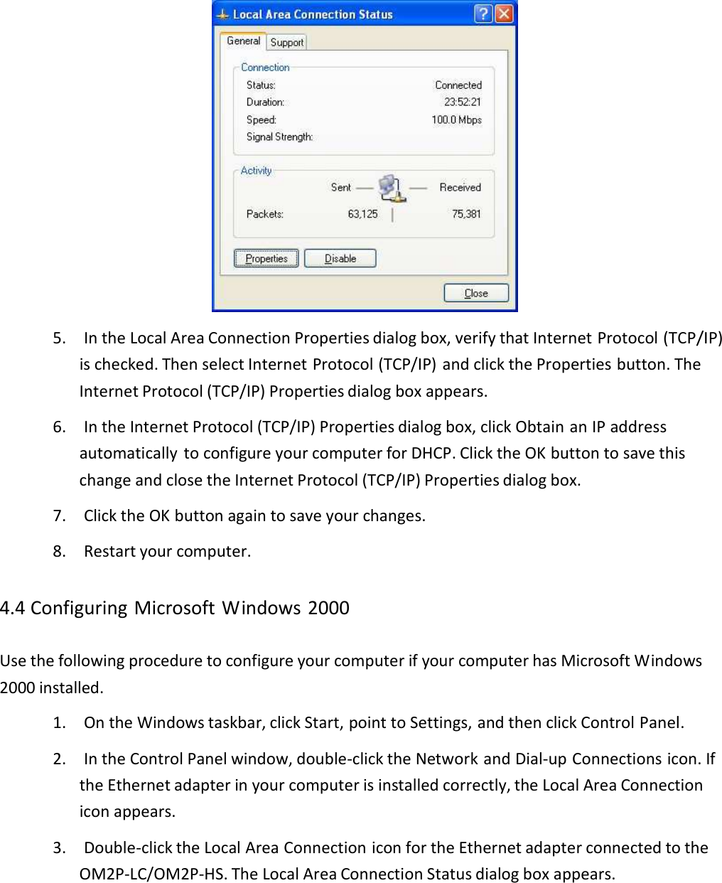
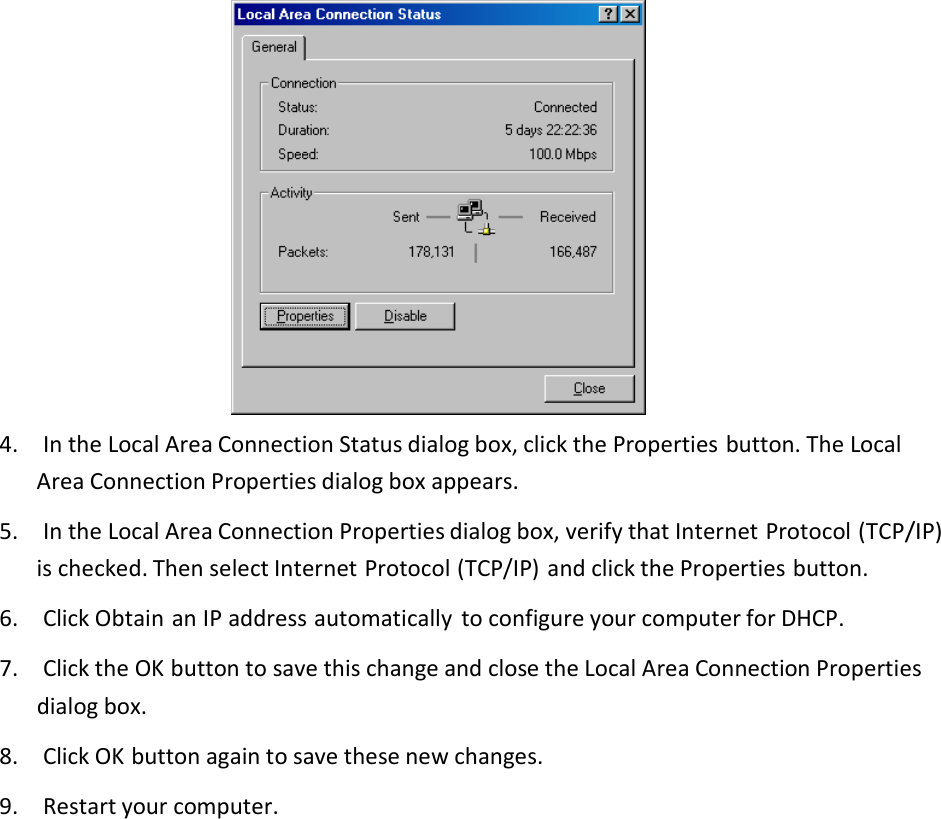
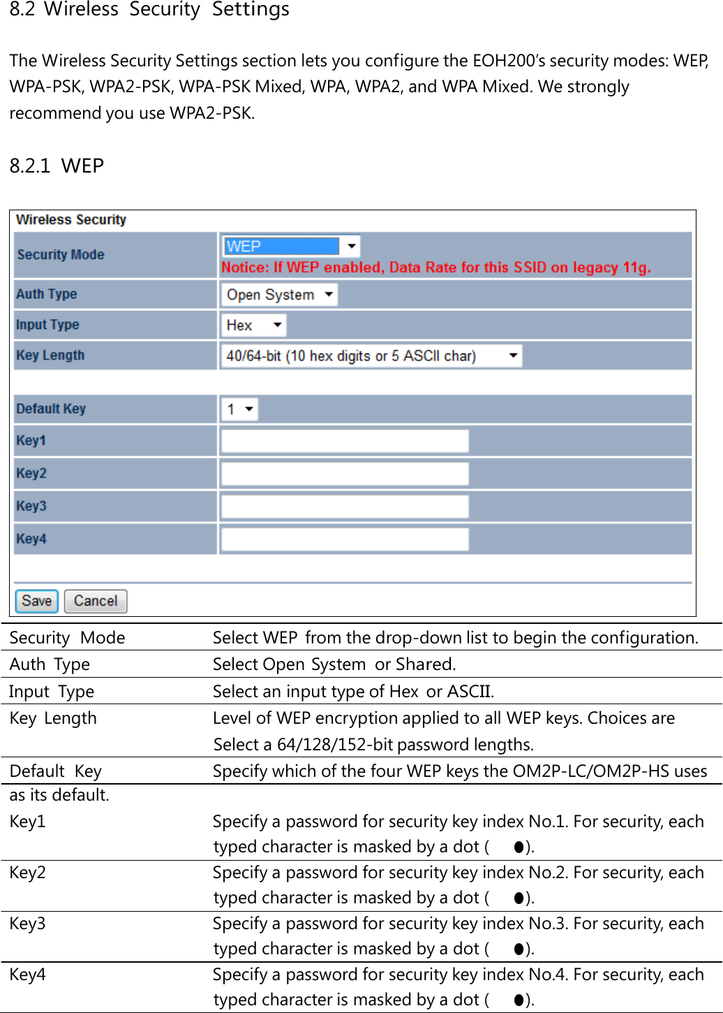
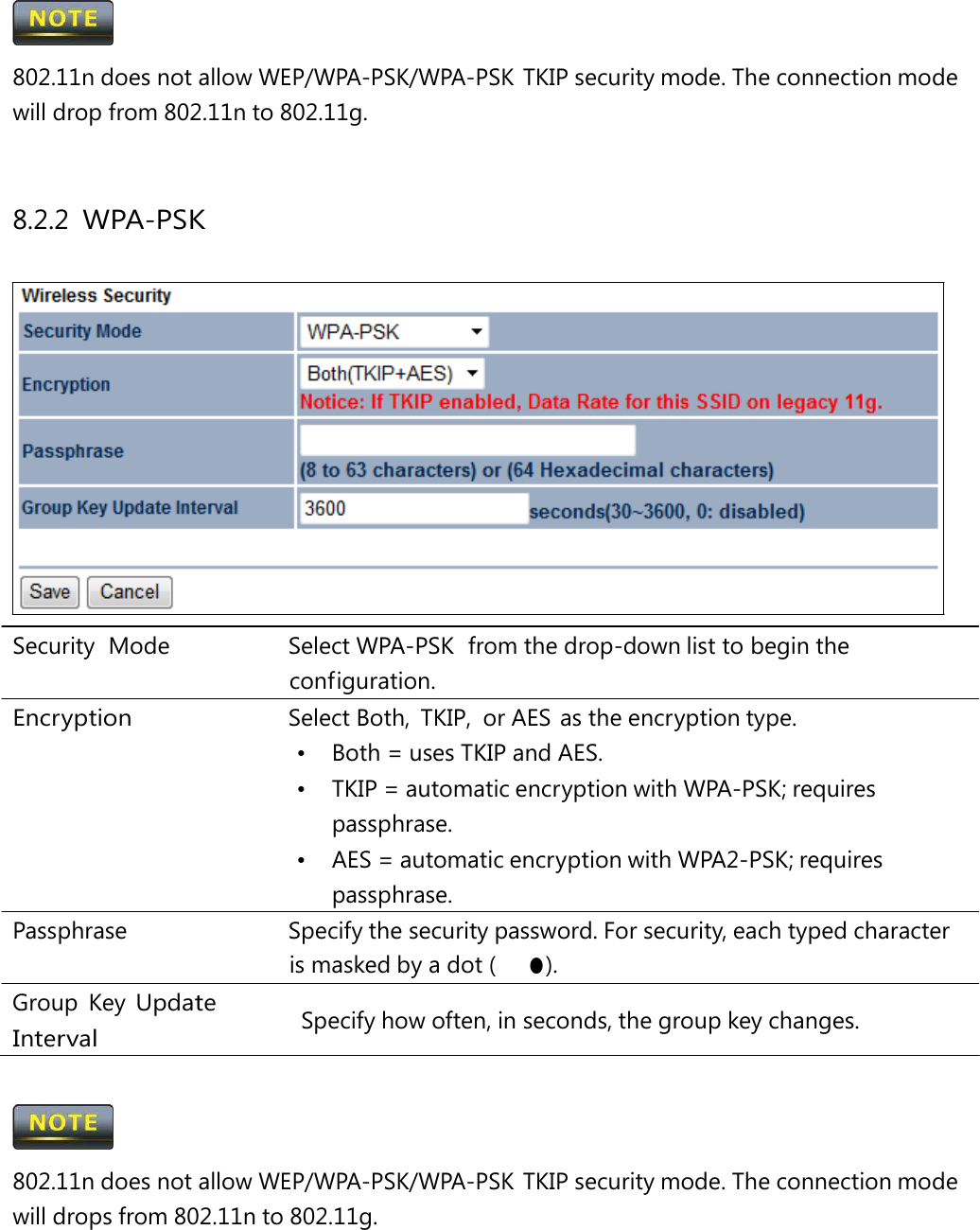
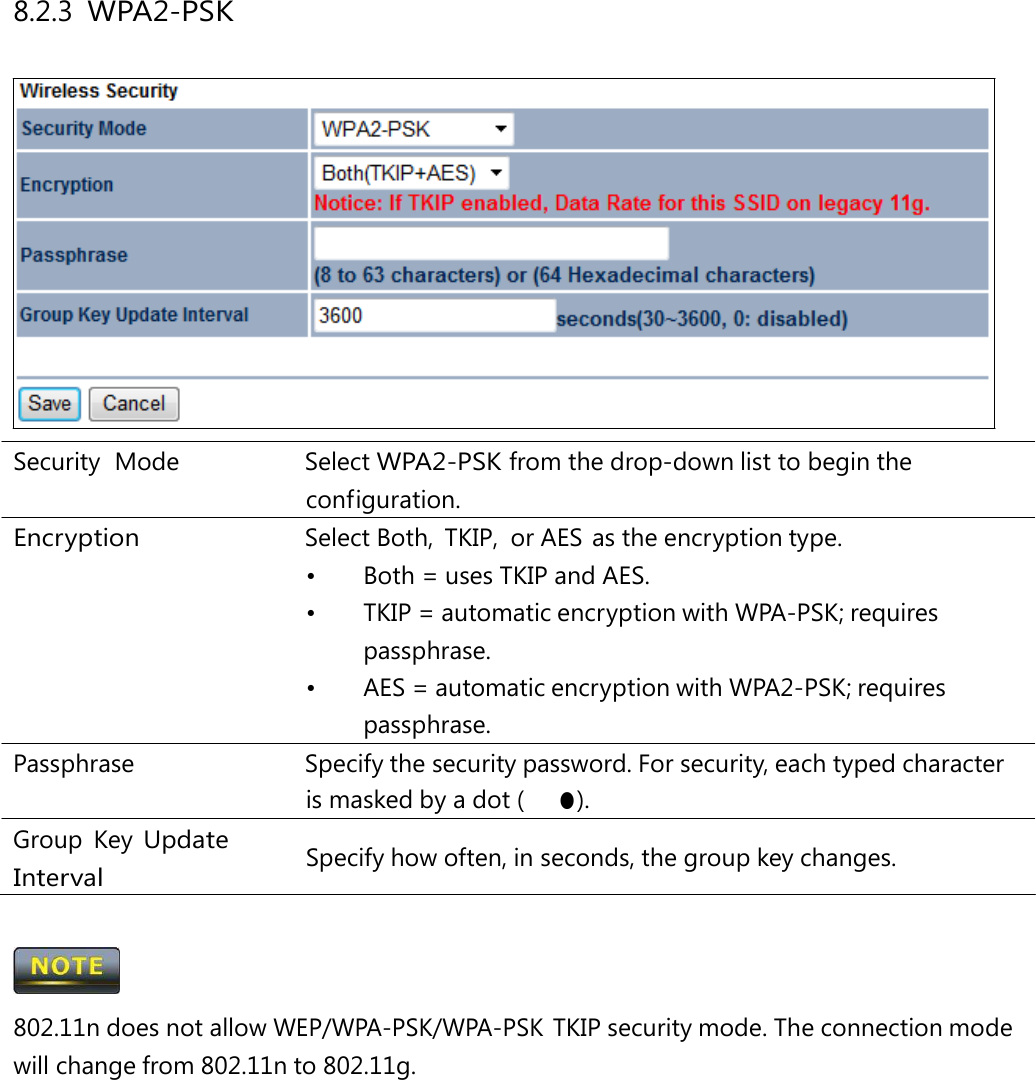
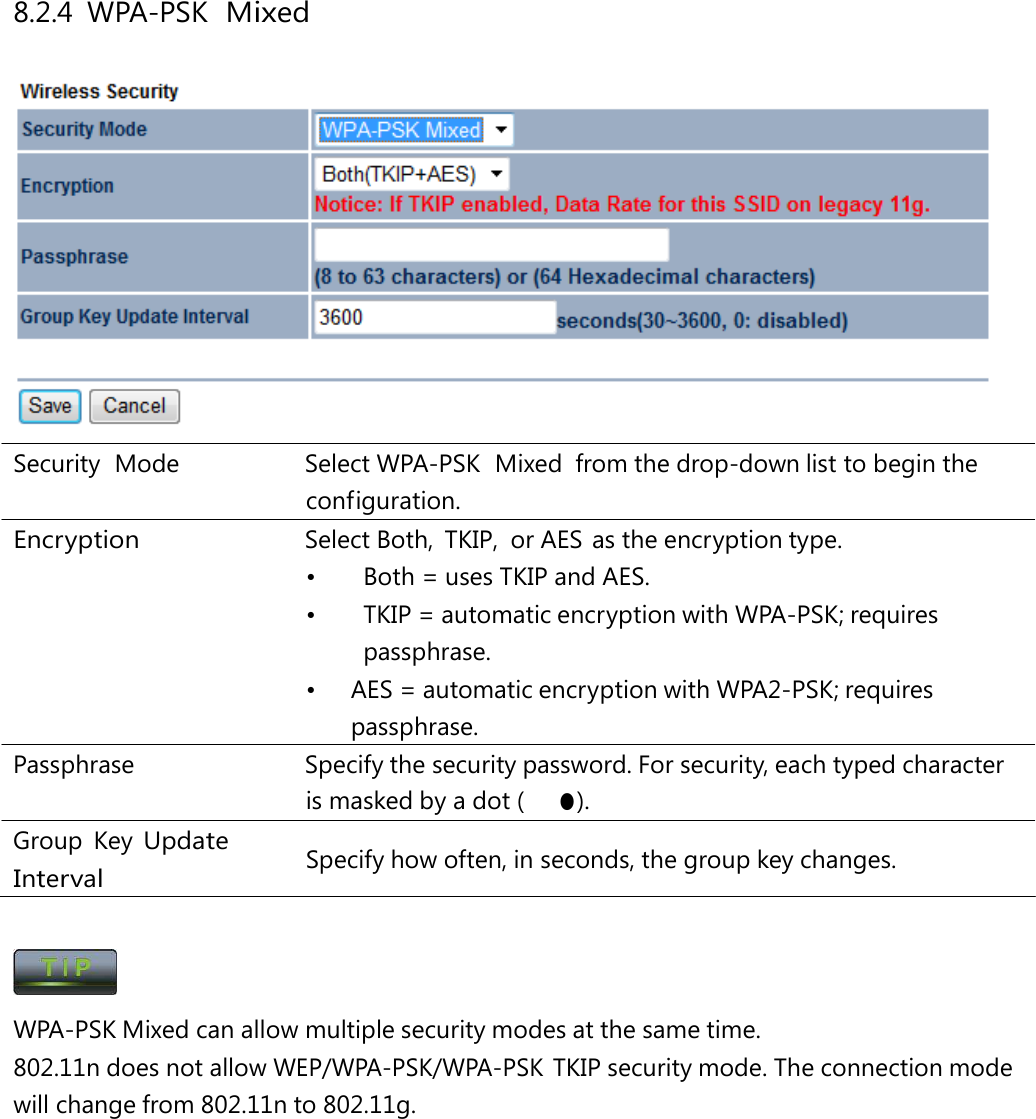
User Manual
Discussion / Help
Navigation