Davis Instruments DWW6310 Weather Station User Manual Vantage Pro Manual draft
Davis Instruments Weather Station Users Manual Vantage Pro Manual draft
Contents
- 1. Manual
- 2. Users Manual Vantage Pro Manual draft
Users Manual Vantage Pro Manual draft


Vantage Pro Manual Page 3
WELCOME TO THE VANTAGE PRO . . . . . . . . . . . . . . 7
Vantage Pro Formats . . . . . . . . . . . . . . . . . . . . . . . . . . . . . . . . .7
Display & Keyboard . . . . . . . . . . . . . . . . . . . . . . . . . . . . . . . . . .8
Console Modes . . . . . . . . . . . . . . . . . . . . . . . . . . . . . . . . . . . . .8
Multiple stations / Sensors . . . . . . . . . . . . . . . . . . . . . . . . . . . . .8
OPTIONAL S ENSORS . . . . . . . . . . . . . . . . . . . . . . . . . . 9
OPTIONAL ACCESSORIES . . . . . . . . . . . . . . . . . . . . . . . 10
VANTAGE PRO CONSOLE INSTALLATION . . . . . . . . . 11
CABLED VANTAGE PRO CONSOLE INSTALLATION . . . . . 12
Powering your Vantage Pro . . . . . . . . . . . . . . . . . . . . . . . . . . .12
Connecting the Cabled Vantage Pro to the
Integrated Sensor Suite (ISS) . . . . . . . . . . . . . . . . . . . . . . .13
Wireless Vantage Pro Installation . . . . . . . . . . . . . . . . . . . . . . .14
Powering your Wireless Vantage Pro . . . . . . . . . . . . . . . . . . . .14
Establishing reception between the Wireless Vantage Pro console
to the Integrated Sensor Suite (ISS) . . . . . . . . . . . . . . . . . .14
DISPLAYING THE VANTAGE PRO CONSOLE . . . . . . . . . . 15
Table & Shelf Display . . . . . . . . . . . . . . . . . . . . . . . . . . . . . . . . .15
Wall Display . . . . . . . . . . . . . . . . . . . . . . . . . . . . . . . . . . . . . . . .16
USING THE VANTAGE PRO CONSOLE
KEYBOARD . . . . . . . . . . . . . . . . . . . . . . . . . . . . . . . 18
Using the Navigation Keys . . . . . . . . . . . . . . . . . . . . . . . . . . . .18
DISPLAY FEATURES . . . . . . . . . . . . . . . . . . . . . . . . . . . 19
SETUP MODE . . . . . . . . . . . . . . . . . . . . . . . . . . . . . . . . 22
Entering & Exiting Setup Mode . . . . . . . . . . . . . . . . . . . . . . . . .22
Setup Mode Screens . . . . . . . . . . . . . . . . . . . . . . . . . . . . . . . . .22
Setup Mode - Screen 1: Transmitters 22
23
Setup Mode - Screen 2: Selecting Transmitters23
Setup Mode - Screen 3: Retransmit 24
Setup Mode - Screen 4: Time & Date 24
Setup Mode - Screen 5: Latitude 24

Vantage Pro Manual Page 4
Setup Mode - Screen 6: Longitude 25
Setup Mode - Screen 7: Time Zone 25
Setup Mode - Screen 8: Daylight Savings Detection 25
Setup Mode - Screen 9: Daylight Savings Status 25
Setup Mode - Screen 10: Elevation 25
Setup Mode - Screen 11: Wind Cup Size 25
Setup Mode - Screen 12: Rain Collector 26
Setup Mode - Screen 13: Rain Season 26
Exiting Setup Mode . . . . . . . . . . . . . . . . . . . . . . . . . . . . . . . . . .26
CURRENT WEATHER MODE . . . . . . . . . . . . . . . . . . . . . 26
Activating Weather Variables . . . . . . . . . . . . . . . . . . . . . . . . . .26
Wind Speed and Direction 27
Temperature 27
Humidity 27
Wind Chill 28
Dew Point 28
Barometric Pressure 28
UV (Ultraviolet Radiation) 29
Heat Indices 29
Rain “Year”, Rain “Month”, and Rain Rate 29
“Daily” and “Storm” Rain 30
Solar Radiation 31
ET (Evapotranspiration) 31
Selecting Units 32
To change the units for any variable: 32
HIGHS AND LOWS MODE . . . . . . . . . . . . . . . . . . . . . . . 33
Accessing Highs and Lows . . . . . . . . . . . . . . . . . . . . . . . . . . . . . 33
Exit Highs and Lows screen . . . . . . . . . . . . . . . . . . . . . . . . . . . . 34
ALARMS MODE . . . . . . . . . . . . . . . . . . . . . . . . . . . . . . . 35
Three special alarms . . . . . . . . . . . . . . . . . . . . . . . . . . . . . . . . .35
ETo (Evapotranspiration) 35
Barometric Pressure 35
Time 35
Setting Alarms . . . . . . . . . . . . . . . . . . . . . . . . . . . . . . . . . . . . . .35
Setting the Time Alarm . . . . . . . . . . . . . . . . . . . . . . . . . . . . . . .36

Vantage Pro Manual Page 5
Clearing Alarms . . . . . . . . . . . . . . . . . . . . . . . . . . . . . . . . . . . . .36
GRAPH MODE 39
Entering and Exiting Graph Mode . . . . . . . . . . . . . . . . . . . . . . . 39
Using and Understanding the Graph Mode’s Features . . . . . . .39
TROUBLESHOOTING . . . . . . . . . . . . . . . . . . . . . . . . 41
DISPLAY . . . . . . . . . . . . . . . . . . . . . . . . . . . . . . . . . . . . 42
TEMPERATURE . . . . . . . . . . . . . . . . . . . . . . . . . . . . . 43
HUMIDITY . . . . . . . . . . . . . . . . . . . . . . . . . . . . . . . . . . 44
WIND S PEED . . . . . . . . . . . . . . . . . . . . . . . . . . . . . . . . 44
DIRECTION . . . . . . . . . . . . . . . . . . . . . . . . . . . . . . . . . . 44
CHILL . . . . . . . . . . . . . . . . . . . . . . . . . . . . . . . . . . . . . . 44
RAIN . . . . . . . . . . . . . . . . . . . . . . . . . . . . . . . . . . . . . . 45
APPENDIX :
WEATHER DATA . . . . . . . . . . . . . . . . . . . . . . . . . . 47
WEATHER CONDITIONS MEASURED /CALCULATED . . . . . 47
Wind . . . . . . . . . . . . . . . . . . . . . . . . . . . . . . . . . . . . . . . . . . . . .47
Temperature . . . . . . . . . . . . . . . . . . . . . . . . . . . . . . . . . . . . . . .47
Apparent Temperature Measures . . . . . . . . . . . . . . . . . . . . . . .47
Relative Humidity . . . . . . . . . . . . . . . . . . . . . . . . . . . . . . . . . . .49
Dew-Point . . . . . . . . . . . . . . . . . . . . . . . . . . . . . . . . . . . . . . . . .50
Rainfall . . . . . . . . . . . . . . . . . . . . . . . . . . . . . . . . . . . . . . . . . . . .50
Barometric Pressure . . . . . . . . . . . . . . . . . . . . . . . . . . . . . . . . .50
Solar Radiation . . . . . . . . . . . . . . . . . . . . . . . . . . . . . . . . . . . . . .51
UV (Ultra Violet) Radiation . . . . . . . . . . . . . . . . . . . . . . . . . . . .51
EvapoTranspiration (ET) . . . . . . . . . . . . . . . . . . . . . . . . . . . . . .54
Leaf Wetness . . . . . . . . . . . . . . . . . . . . . . . . . . . . . . . . . . . . . . .54
Soil Moisture . . . . . . . . . . . . . . . . . . . . . . . . . . . . . . . . . . . . . . .54
Time . . . . . . . . . . . . . . . . . . . . . . . . . . . . . . . . . . . . . . . . . . . . .54
REPAIR & W ARRANTY INFORMATION . . . . . . . . . . . 59

Page 6 Vantage Pro Console Manual
ONE YEAR LIMITED WARRANTY . . . . . . . . . . . . . . . . . . 59
QUESTIONS ? CALL THE DAVIS SERVICE CENTER . . . . . 59
FCC P ART 15 CLASS B R EGISTRATION WARNING . . . . 60
Vantage Pro Manual Page 7
WE L C O M ET O T H E VA N T A G EPR O
Welcome to Davis Instruments’ Vantage Pro weather station console. The Van-
tage Pro console, part of the comprehensive Vantage Pro system, displays a
wealth of weather information -- up to ten weather variables simultaneously.
The Vantage Pro console is also a powerful weather computer, collecting, stor-
ing, and displaying historical data, including highs and lows, in graphical and
numerical formats.
The Vantage Pro also provides you with a forecast based on the latest meteoro-
logical algorithms. A quick glance at the graphical icons predicts the general
weather trend and a detailed forecast scrolls across the bottom of the screen,
letting you know what to expect!
Vantage Pro Formats
The Vantage Pro System is available in two formats: Cabled and Wireless.
• Cabled Vantage Pro System
The Cabled Vantage Pro system links the Integrated Sensor Suite (ISS)
sensor array to the console with standard four-conductor cable. The
Standard Vantage Pro system operates on AC power only (w/ battery
backup).
• Wireless Vantage Pro
The wireless Vantage Pro console receives data transmitted by radio
from the solar-powered (with battery backup)ISS. Neither the sensor
array, nor the console requires AC power in the wireless format.
1

Page 8 Vantage Pro Console Manual
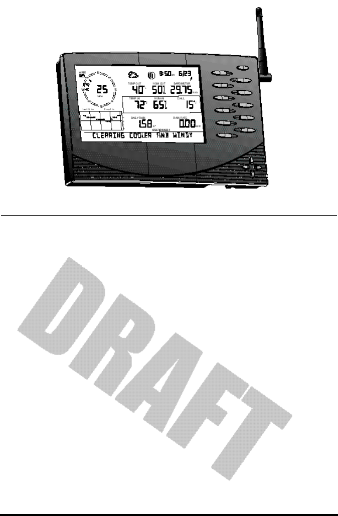
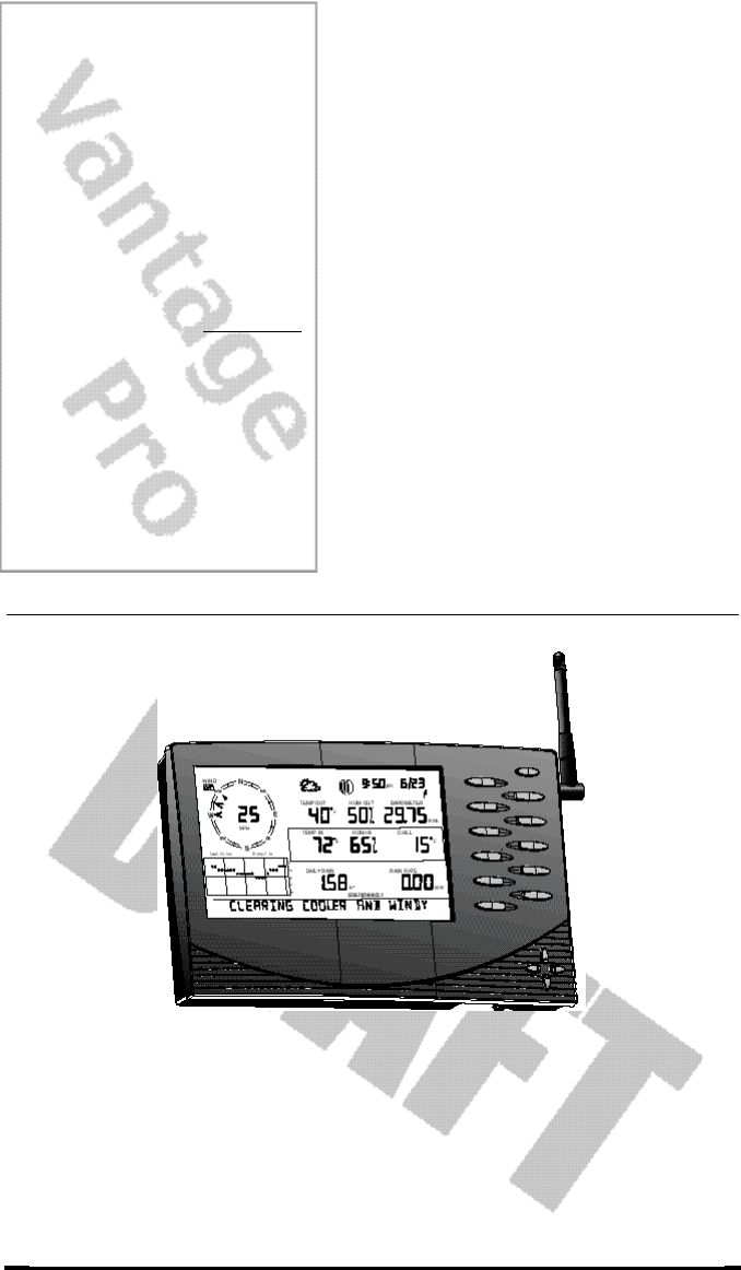
Display & Keyboard
The Vantage Pro display and keyboard are designed for easy access to the most
important weather information.
The keyboard allows you to interact with the station computer, view current
and historical data, set and clear alarms, change station modes, enter calibra-
tion numbers, set up and view graphs, select sensors, read the forecast, and so
on. To learn more about the keyboard, see “Keyboard” on page 18.
The Large LCD display is your window on current and past environmental
conditions, as well as the place to find the forecast. The console LCD can dis-
play up to 10 weather variables at any one time. To learn more about the dis-
play’s features, see “Display Features” on page 19.
Console Modes
The Vantage Pro console operates in five different modes designed to give you
quick and easy access to the information you need:
• Setup
Setup mode is used to enter the time, date, calibration numbers, and
other information required for the processing and display of the weather
data.
• Current Data
Current data is the most common operation mode. In this mode you can
read the current weather information and access any weather data not
currently displayed using the keyboard.
• High / Low
The High and Low mode summaries are accessed using the High/Low
key.
• Alarm
Alarm mode allows the user to set, clear, and review alarm settings.
• Graph
Graph mode allows the user to access the advanced graphing capabili-
ties of the Vantage Pro weather computer.
For more information about using the console, see “Using the Vantage Pro
Console” on page 17 and following sections.
Multiple stations / Sensors
The Wireless Vantage Pro system is capable of receiving transmissions from up
to eight different transmitters. See “Optional Sensors” below.

Optional Sensors
Vantage Pro Manual Page 9
OP T IO N A LSE N S O R S
The Vantage Pro system is extremely flexible. The following optional sensors
enable calculation and measurement of specialized weather information. All
optional sensors are available from your dealer or may be ordered directly
from Davis Instruments. Please be aware that some options are available only
for wireless units.
• Solar Radiation Sensor
Enables you to measure and display solar irradiance. Also required for
calculating Evapotranspiration (see “Wind” on page 47).
Available for Cabled and Wireless stations. Requires Sensor Mounting
Shelf. See “Optional Accessories” on page 10.
• Ultraviolet (UV) Radiation Sensor
Enables you to measure and display UV wavelength irradiance.
Required for calculating the UV dose.
Available for Cabled and Wireless stations. Requires Sensor Mounting
Shelf. See “Optional Accessories” on page 10.
Note: The Wireless Vantage Pro console is capable of receiving signals from up to eight separate transmitter
stations, including:
• Wireless Integrated Sensor Suite
A complete sensor package including Rain, Temperature, Humidity,
Wind Speed and Direction, with options for Solar Radiation and UV sen-
sors. The Vantage Pro Console/Receiver accomodates one ISS transmit-
ter station.
• Wireless Temperature Station
Measures and transmits air temperature from a remote location to the
console. The Vantage Pro Console/Receiver accomodates up to eight
Wireless Temperature Stations.
• Wireless Temperature / Humidity Station
Measures and transmits air temperature and humidity from a remote
location to the console. The Vantage Pro Console/Receiver accomodates
up to eight Wireless Temperature/Humidity stations.
• Anemometer Transmitter Kit
Allows separation of anemometer from ISS to capture wind speed and
direction from a remote location. The Vantage Pro Console Receiver
accomodates one Anemometer Transmitter Kit.
• Wireless Soil Moisture / Temperature Station
Measures and transmits soil moisture and temperature data from up to
four sensors each. The Vantage Pro Console Receiver accomodates one
Soil Moisture / Temperature station.

Page 10 Vantage Pro Console Manual
• Wireless Leaf Wetness / Temperature Station
Measures and transmits leaf wetness and temperature data from up to
four sensors each. The Vantage Pro Console/Receiver accomodates one
Leaf Wetness/Temperature station.
Note: The Wireless Vantage Pro Console / Receiver can receive from up to eight transmitters. For example,
as listed above, you may configure your Wireless Vantage Pro system with one ISS, one Wireless Soil
Moisture / Temperature station, one Anemometer Transmitter Kit, three WirelessTemperature /
Humidity stations, and two Wireless Temperature stations.
OP T IO N A LAC C E S S O R I E S
The following accessories, designed for use with the Vantage Pro, are available
from your dealer or may be ordered directly from Davis Instruments.
• WeatherLink® for Vantage Pro™ Data Logger & PC Software
Logs data gathered by the Vantage Pro, downloads it to your PC, and
generates reports and graphical displays. Storage interval (1, 5, 10, 15,
30, 60, or 120 minutes) is set by the user. The data logger will store
approximately 2, 9, 18, 27, 53, 107, or 213 days worth of data depending
on the selected storage interval. Windows™-compatible software lets you
analyze, plot, print, sort, and summarize the data.
WeatherLink® for Vantage Pro™ includes data logger, eight foot cable ,
software, and manual. Requires IBM compatible PC running Windows
95, 98, 2000, ME, or NT and one free serial port.
• WeatherLink™ 8’ extension cord
Extends the distance between Vantage Pro console and computer to a
maxium of 48 feet (14.5 m).
• Solar Radiation Sensor/ UV Sensor Mounting Shelf
Required for mounting the optional Solar Radiation and / or UV Sen-
sors. The mounting shelf attaches to the ISS.
• Cigarette Lighter Power Adapter
Allows the Vantage Pro to draw power from a standard car cigarette
lighter.
Warning: Do not use an older Davis AC Power Adapter or older Davis Cigarette Lighter Adapter.
You will damage the circuitry inside the unit. Use only the Vantage Pro power adapters.
• Telephone Modem Adapter
Allows a dialup connection between the station and the computer.
Vantage Pro Manual Page 11
Chapter 2VA N T A G EPR O
CO N S O L E
IN S T A L L A T I O N
The Vantage Pro console is a precision instrument designed to give extremely
accurate readings. As with any precision instrument, care must be used in its
assembly and use. Although installation of the Vantage Pro console is relatively
simple, following the steps outlined in this chapter-- and assembling the Van-
tage Pro correctly from the start-- will ensure that you will enjoy all of its fea-
tures with a minimum of time and effort.
Vantage Pro Console Installation
Page 12 Vantage Pro Manual
CA B L E D VA N T A G EPR O CO N S O L EIN S T A L L A T I O N
The Cabled Vantage Pro is powered by 5-volt DC (direct current) with battery
backup. Power may be supplied by an AC adapter, or with Davis’ optional 12
to 5-Volt Car/Boat/RV power adapter. (See “Optional Accessories” on
page 10.)
• WARNING: The Vantage Pro system uses power differenly from the way older Davis stations did. Use only
a Davis Vantage Pro 9-volt power converter. Using an older Davis adapter will damage your Vantage Pro!
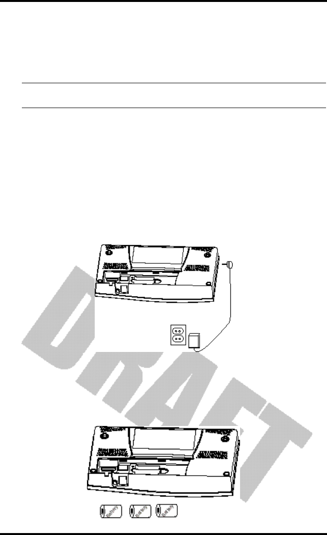
Powering your Vantage Pro
Because the Cabled Vantage Pro console supplies power to the sensor array
through the connecting cable, you must use the AC power adapter or the
optional Car/Boat/RV adapter to supply primary power. The three C-cell bat-
teries provide backup power and will operate the station for four to six weeks
only.
1. Insert the power adapter plug into the jack located on the right side of the console,
then plug the other end of the adapter into an appropriate power outlet.
The Vantage Pro should run through a brief self-test procedure. All the dis-
play segments on the LCD appear and the console will beep twice.
2. Insert the C-cell battery backup.
Remove the battery cover located on the back of the console. Insert 3 C bat-
teries into the battery channel, negative (or flat) terminal first. Push gently
on the last battery to seat all three in the channel and complete the circuit.
Cabled Vantage Pro Console Installation
Vantage Pro Manual Page 13
Note: To remove batteries, place the Vantage Pro Console face down on a flat, firm surface. Insert a finger-
tip between the two exposed batteries. Press the middle battery down toward the notch (toward the
“hidden” battery. This will relieve the tension on the first battery and allow you to withdraw it.
3. Replace the battery cover.
After power-up the Vantage Pro will automatically enter Setup Mode. Setup
mode will lead you through setting up and calibrating your station. See “Setup
Mode” on page 22.
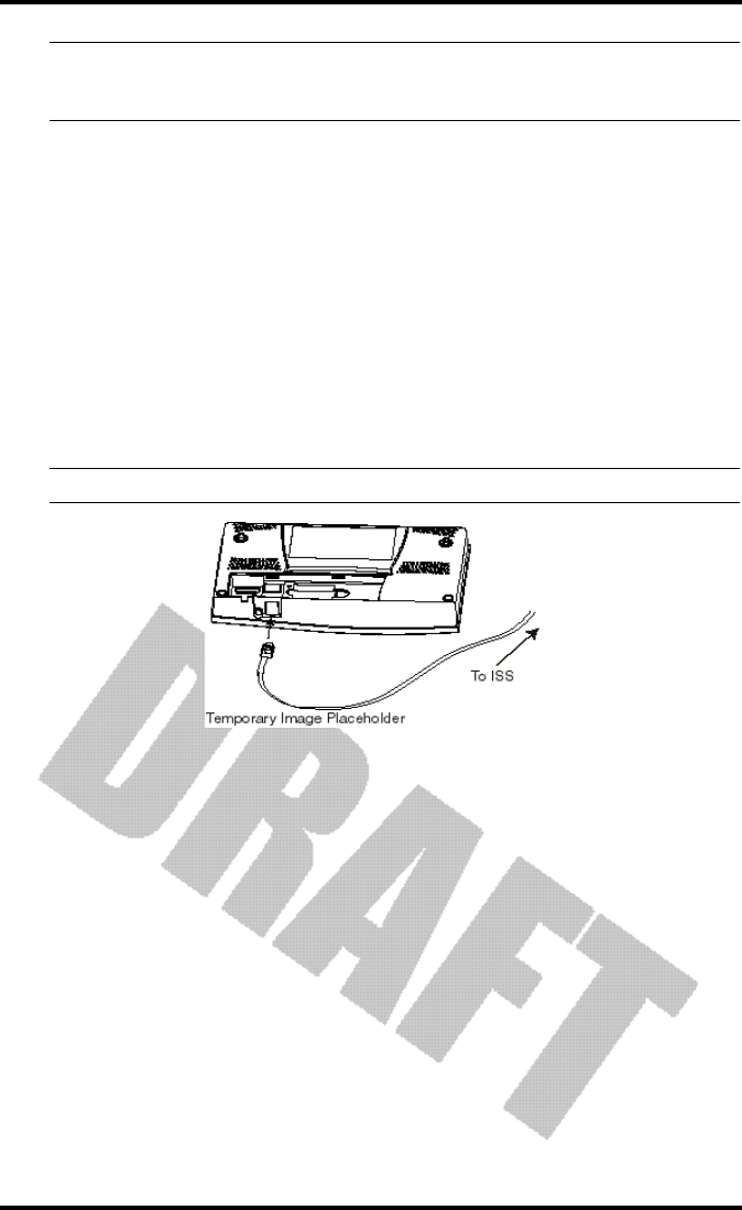
Connecting the Cabled Vantage Pro to the
Integrated Sensor Suite (ISS)
The Vantage Pro comes with 40 feet of cable. Maximum cable length from ISS
to console is 1000 feet. See “Optional Accessories” on page 10 to purchase addi-
tional cable.
1. Gently insert the console end of the 4 conductor wire running from the ISS into the
console receptacle marked ISS until it clicks into place.
• WARNING: Do not force the connector into the receptacle.
2. Ensure that the ISS cable is not twisted through the access hole.
3. Test the connections between the ISS and the console.
Spin the wind cups and change the direction of the vane. If the ISS is pow-
ered and the connection between the ISS and the console is correct, you
should see the wind direction and speed fields changing. Tip the rain bucket
back and forth. You should see rain registering. Check the other fields to
ensure you’re receiving from them, too.

Vantage Pro Console Installation
Page 14 Vantage Pro Manual
Wireless Vantage Pro Installation
Powering your Wireless Vantage Pro
Because the Wireless Vantage Pro console does not supply power to the sensor
array, an AC adapter is not required to operate the console (although you may
use one if you wish).
1. Remove the battery cover from the back of the Vantage Pro console.
2. Insert 3 C-cell batteries as shown.
Insert the negative (or flat) terminal first. The Vantage Pro should run
through a brief self-test procedure. All the display segments appear and the
console will beep three times.
3. Replace the battery cover.
Note: Regarding Battery Use. Under normal circumstances, 3 C cell alkaline batteries should power your
wireless Vantage Pro console for approximately 1 year. Davis Instruments does not recommend using
rechargeable NiCad batteries with the Vantage Pro, because the Vantage Pro will not recharge them
and they will not last as long.
After powering up and running through its self-test mode, the Vantage Pro
console will automatically enter Setup Mode. Setup Mode will lead you
through setting up and calibrating your station. (See “Setup Mode” on
page 22.)
Establishing reception between the Wireless Vantage Pro console
to the Integrated Sensor Suite (ISS)
As you position your console, be aware of possible interference from cordless
phones and other items. To prevent interference, maintain a distance of 10 feet
between the Vantage Pro console and the cordless phone (handset and base).
Also, for best reception, avoid positioning the console near large metallic sur-
faces (e.g., most refrigerator surfaces).
Please test communications between the Console/Receiver and the ISS (or
other transmitter) BEFORE permanently mounting your ISS. Remember that
the ISS transmits packets every few seconds. Therefore, there may be a 2 to 3
second delay before the console display updates. For more information about
locating the sensor transmitter and testing reception, consult the ISS or other
transmitter manual.
Displaying the Vantage Pro Console
Vantage Pro Manual Page 15
DIS P L A Y I N GT H E VA N T A G EPR O CO N S O L E
You should place the Vantage Pro computer console indoors, in a location
where the keyboard is easily accessible and the display is easy to read. For
more accurate readings, follow these suggestions:
• Avoid placing the Vantage Pro console in direct sunlight. The casing heats up in
direct sunlight. This may cause erroneous readings and / or damage to the unit.
• Avoid placing the Vantage Pro console near radiant heaters or heating / air condi-
tioning ducts
•If you are mounting the Vantage Pro console on a wall, choose an inner or interior
wall. Avoid walls that heat up or cool down depending on the weather.
By changing the orientation of the kickstand, you may display the Vantage Pro
on a tabletop, set it on a shelf, or mount it on a wall.
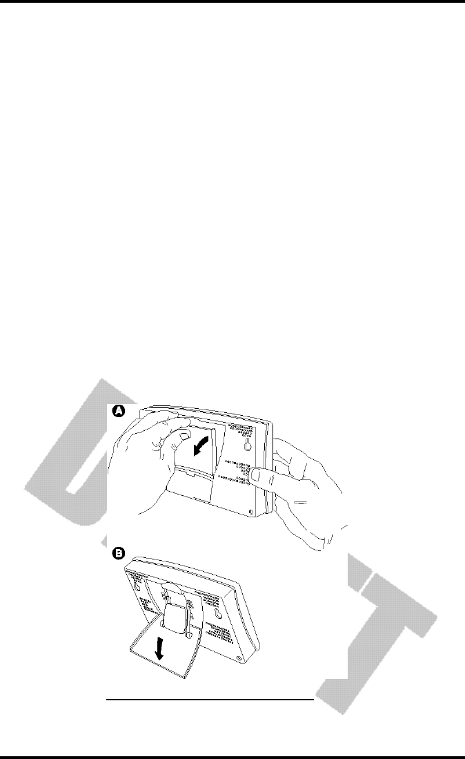
Table & Shelf Display
The kickstand may be set at five different angles appropriate for different dis-
play angles.
1. Lean the kickstand out.
2. Slide the catch to arrest the kickstand in the appropriate angle.
Choose low angles (settings 1 & 2) for display on a coffee table or other low
area. Choose higher angles (settings 3 - 4) for display on a desk or shelf.
OPENING THE STAND FOR TABLE OR SHELF DISPLAY
Vantage Pro Console Installation
Page 16 Vantage Pro Manual
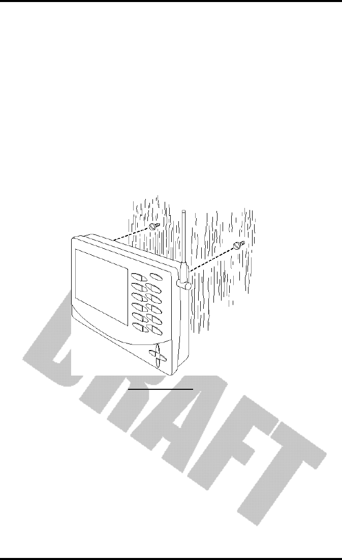
Wall Display
1. Hold the template provided here flat against the wall and use a pencil to mark the
location of the two keyholes.
If you are installing a standard Vantage Pro console with sensor cable run-
ning inside the wall, attach the console over an empty switch box.
<!-- get dimensions and make template --!>
2. Use an electric drill with a #29 (.136” or 3.5mm) drill bit to make pilot holes in these
locations.
3. Using a screwdriver, drive the two #8 x 3/4” pan head self-threading screws into the
wall. Leave at least 1/8” between the wall the the heads of the screws.
4. Retract the kickstand into its upright and locked position.
5. Slide the keyholes on the back of the console over the two screw heads.
AFFIXING TO A WALL
Vantage Pro Manual Page 17
US I N G T H E VA N T A G EPR O CO N S O L E
The Vantage Pro display and keyboard are designed for easy access to the most
important weather information. The large LCD display is your window on cur-
rent and past environmental conditions, as well as the place to find the forecast.
The keyboard allows you to interact with the station computer, view current
and historical weather information, set and clear alarms, change station modes,
enter calibration numbers, set up and view graphs, select sensors, read the
forecast, and so on.
CH A P T E R3
Chapter 3
Page 18 Vantage Pro Console Manual
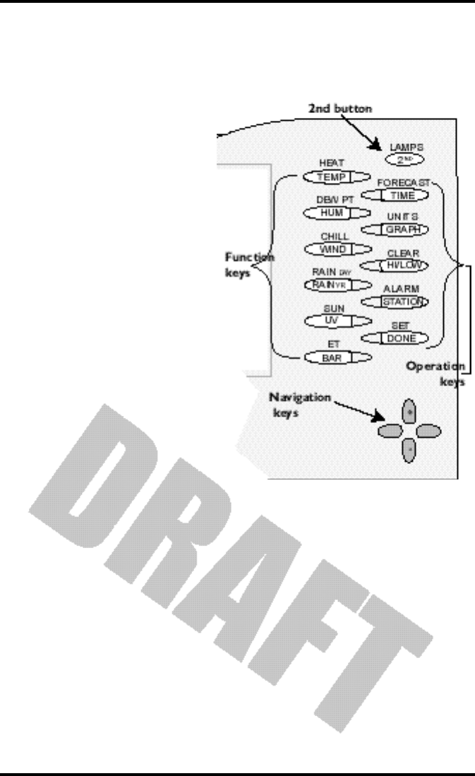
KE Y B O A R D
To access the station’s many features, the Vantage Pro console possesses three
kinds of keys:
• Function keys
The six primary function keys,
TEMP (Temperature), HUM
(Humidity), WIND (Wind speed
and direction), RAIN YR (Total
Year Rain), UV (Ultra-Violet irra-
diance), and BAR (Barometer)
are used to access current
weather information. They lie in
the left side of the double key
column.
• Operation keys
The six operation keys lie on the
right side of the double column.
2ND, TIME, GRAPH, HI/LOW,
STATION, and DONE are used
to enter different console modes,
set and clear alarm values,
change measurement units,
select station transmitters, and so
on.
There is a special operation key,
the 2ND key, located in the
upper right hand corner of the
keypad.
• The 2nd key
The second key is used in conjuction with other keys to access alternate func-
tions. Above each function and operation key lies a legend identifying that
key’s alternate use. For example, FORECAST is listed above the TIME key. To
access the Vantage Pro’s forecast, press and release the 2nd key, then press and
release the TIME/FORECAST key.
• Navigation keys
The four navigation keys, two horizontal and two vertical, are arrayed in a
cross shape in the lower right corner of the console. The Navigation keys are
used to enter or change data, and to scroll between displays.
Using the Navigation Keys
You should become familiar with the use of these keys, since they serve many
purposes in operating the Vantage Pro. The Navigation keys are used the same
way, regardless of the current console mode.
Display Features
Vantage Pro Console Manual Page 19
Essentially, pressing the right or left navigation key activates the next (or previ-
ous) data field on the screen. The up and down navigation keys scroll through
digits or entries.
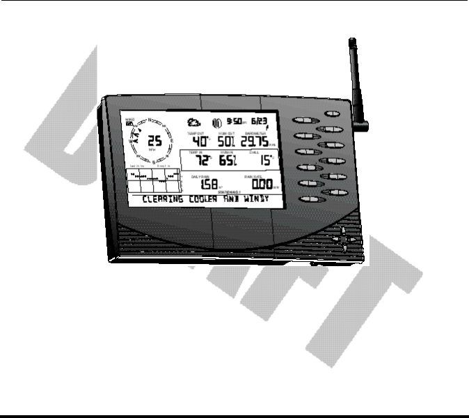
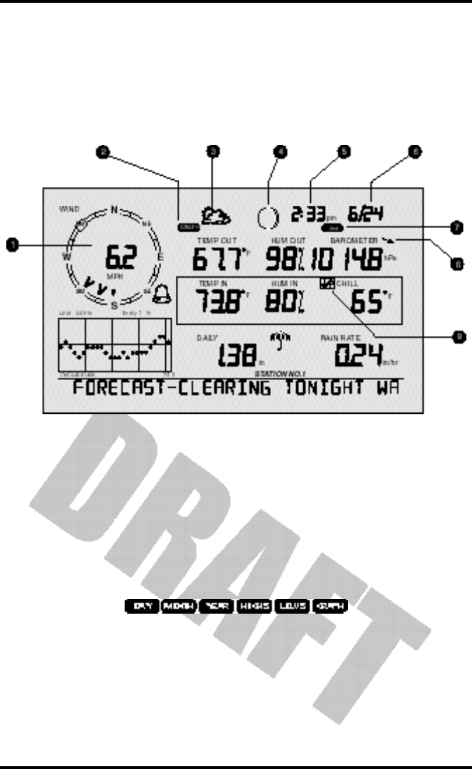
DIS P L A Y FE A T U R E S
The large LCD display is your window on current and past environmental con-
ditions, as well as the place to find the forecast.
The display is organized to maximize the information available to you. The
following section explains some of the features that may appear on your con-
sole.
1. Compass Rose
The wind rose displays the speed and direction of the current wind, as well
as the variation in the 10 minute dominant wind direction over the last 60
minutes
2. Graph and Hi / Low mode settings
Combinations of these indicators appear only when the Hi /Low or Graph
modes are selected.
Vantage Pro console display
Chapter 3
Page 20 Vantage Pro Console Manual
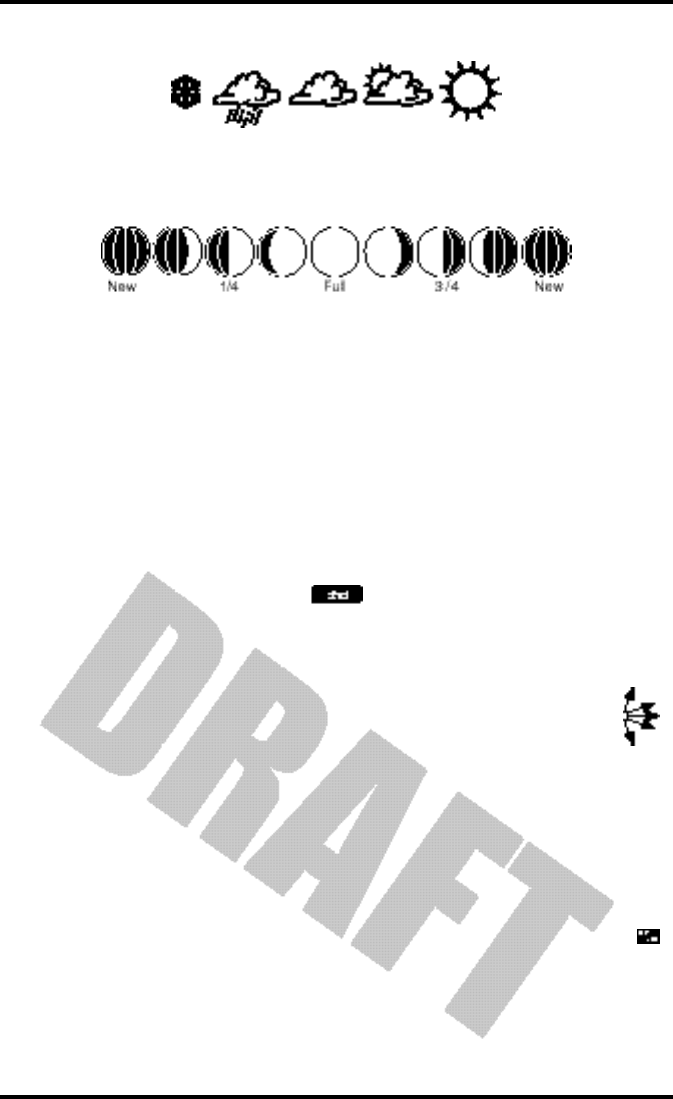
3. Forecast Icons
From left to right, these icons represent predicted snow, rain, clouds, partly
cloudy, and sun. The forecast is updated every hour.
4. Moon Phase Indicator
The moon phase indicator depicts the current phase of the moon.
5. Time / Sunrise Time
Time may be displayed in 12 or 24 hour format. Time of sunrise is also dis-
played in this field. (After 6 pm, sunrise for the following day is displayed.)
You must enter the correct latitude and longitude and time zone for your
location for the time of sunrise to be accurate.
6. Date / Sunset Time
Date may be displayed in day / month or month.day format. Time of sunset
is also displayed in this field. You must enter the correct latitude and longi-
tude and time zone for your location for the time of sunset to be accurate.
7. 2nd button indicator
The 2nd indicator icon lights when the 2nd button is pushed.
8. Barometric Trend Arrow
The barometric trend arrow displays the pressure trend in five dif-
ferent positions: strongly rising, rising, steady, falling, and strongly
falling.
The steeply rising (or falling) arrow indicates the pressure has
increased (or decreased) 0.06” Hg or more in three hours.
The shallow rising (or falling) arrow indicates the pressure has increased (or
decreased) 0.02” or more Hg, but less than 0.06” Hg over three hours.
A flat arrow indicates the pressure has changed less than 0.02” Hg in three
hours.
9. Graph Icon
The graph icon is always displayed next to the active weather vari-
able. The graph will always show that variable’s history according to
your settings.
Display Features
Vantage Pro Console Manual Page 21
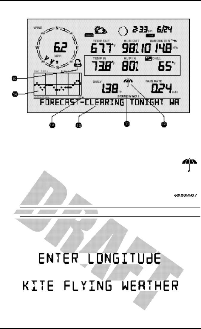
10. Current Rain Indicator
The umbrella icon announces that it is currently raining. It’s acti-
vated by the accumulation of 0.01 in (0.25 mm). The umbrella dis-
appears after 15 minutes with no further rain accumulation.
11. Station Number Indicator
The station number indicator shows which sensor transmitter
the console is currently displaying.
Note: Multiple sensors are available for the wireless Vantage Pro system only.
12. Weather Ticker
The Davis Weather Ticker is a unique and useful addition to the weather sta-
tion console. The ticker displays a broad spectrum of messages to the con-
sole user, including instructions during console setup.
The ticker also displays detailed forecast messages.
13. Graph Field
The graph features an astounding array of features that I haven’t quite fin-
ished thinking about and will write later.
Vantage Pro console display
Chapter 3
Page 22 Vantage Pro Console Manual
14. Alarm icon
The bell icon is active when an alarm is set or when you’re in the ALARM
SET mode. The icon blinks continuously when an alarm is triggered.
SE T U P MO D E
Setup Mode lets you choose settings that determine how your Vantage Pro sta-
tion operates.
Entering & Exiting Setup Mode
The console will automatically enter Setup Mode when you first power up.
Later, if you need to make any changes, access the Setup Mode at any time by
pressing the “DONE” and “down arrow” keys at the same time. Exit Setup at
any time by pressing and holding the “DONE” key until the “Current
Weather” screen appears.
Setup Mode Screens
On entering the Setup Mode, a sequence of screens will appear on the console.
Pressing “DONE” will take you to the next screen in the sequence.
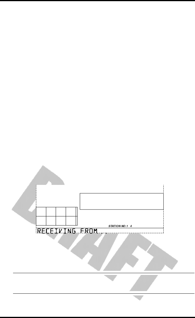
Setup Mode - Screen 1: Transmitters
Screen 1 displays active transmitters located in your area. The ticker will dis-
play the message “Receiving from...” and the active transmitter IDs will be illu-
minated. The rest of the display screen will be blank. Transmitters must be
switched on for the console to recognize them. This screen requires no input; it
simply shows you what transmitters the console can receive.
Press and release the “DONE” key to move to Setup screen 2.
Note: Each Vantage Pro Console/Receiver may receive signals from up to eight different
transmitters ; however, only certain combinations of transmitters are possible. Table 1 below lists
the maximum numbers of transmitter types each console/receiver can handle:
Setup Screen 1: Transmitters. This screen shows the Console receiving
transmssions from transmitter IDs 1 and 4.
Setup Mode
Vantage Pro Console Manual Page 23
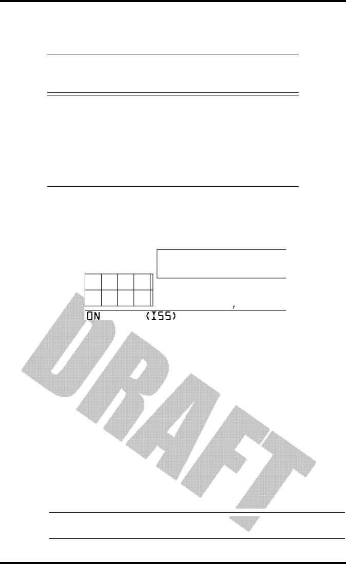
Setup Mode - Screen 2: Selecting Transmitters
Use setup screen 2 to tell the Console/Receiver which transmitter IDs to listen
to, and what kind of station each transmitter represents.
You probably do NOT need to change transmitter IDs. The default transmitter
ID for the ISS is ‘1’. Your console/receiver will assume that Station 1 is your ISS
and should find its transmissions automatically. This should complete Setup
screen 2 for most owners.
In the unlikely event that you do need to change transmitter IDs (e.g. a neigh-
bor is using a Davis product nearby or you have more an optional transmitter
(See “Optional Sensors” on page 9.) read on. Otherwise, skip down to Setup
Screen 3.
To activate reception on different ID codes, press the LEFT or RIGHT arrow
key, or the “STATION” key, to scroll between transmitter IDs.
Note: Station IDs do not have to be in order. The factory default transmitter ID for the ISS is “1”.
See your transmitter’s manual to learn how to set the transmitter ID.
Table 1: Maximum Transmitters per Console/Receiver
Transmitter Type Maximum per
Console (8
total)
Integrated Sensor Suite (ISS) 1
Anemometer Transmitter Kit 1
Leaf Wetness/Temperature Station 1
Soil Moisture/Temperature Station 1
Temperature Station 8
Temperature/Humidity Station 8
Setup Screen 2: Here’s what should greet most new Vantage Pro owners. The con-
sole comes factory pre-set at transmitter ID 1. “ON” means the console will receive
signals from that ID and will assume the transmitter is an ISS. For most owners, this
will complete this step. See the ISS manual for further details.

Chapter 3
Page 24 Vantage Pro Console Manual
• Once you’ve settled on the ID you wish to use, use the "+" or "-" arrow keys to acti-
vate reception of that ID code.
As each different ID illuminates, the ticker will display the word “ON” or
“OFF”. “ON” means the Console/Receiver will “listen” to that transmit-
ter’s signal. “OFF” means the Console/Receiver will ignore signals from
that transmitter.
•Now, press the “GRAPH” key to change the type of station assigned to each transmit-
ter number.
When a station is listed as “ON”, one of the possible station types will be
displayed in the ticker: ISS, TEMP, HUM,TEMP HUM, WIND, LEAF, or
SOIL. Press the “GRAPH” key to scroll through this list until the correct
station type appears.
Press and release the “DONE” key to move to Setup screen 3.
Setup Mode - Screen 3: Retransmit
The Vantage Pro Console/Receiver can re-transmit data to other Console/
Receivers, or to the Davis Weather Echo and Weather Echo Plus.
Note: This feature is not available in the cabled Vantage Pro station.
Setup screen 3 lets you switch the retransmit feature on or off. Use the "+" or "-"
arrow key to choose “Retransmit On” or “Retransmit Off”. Use the STATION
key to choose and assign a transmission ID to the Console/Receiver. Note that
only IDs you’re not already using will appear.
Press and release the DONE key to move to Setup screen 4.
Setup Mode - Screen 4: Time & Date
Use the UNITS key to choose 12 or 24 hour time display. Use the LEFT and
RIGHT arrow keys to move between hours and minutes fields. Use the "+" and
"-" keys to enter digits. When entering the date, use the UNITS key to select
Month/Day or Day.Month display. Enter the month, day, and year.
Setup Mode - Screen 5: Latitude
To give you the best forecast we can, as well as calculate the correct times for
sunset and sunrise for your location, the Vantage Pro Setup will ask you to
enter your latitude and longitude.
Note: Latitude and longitude are a way of identifying your position on the earth. Latitude measures dis-
tance north or south of the equator. Longitude measures distance east or west of the Prime Meridian,
an imaginery line running north and south through Greenwich, England. (The Prime Meridian was set
by international convention at this location in 1884.)

Setup Mode
Vantage Pro Console Manual Page 25
If you do not know your latitude and longitude, there are several ways to find
out. Many atlases include latitude and longitude lines. You can also talk to the
reference department of your local library, or try calling your local airport. The
more accurate you are, the better; however, a reasonable estimate will work,
too.
Use the LEFT and RIGHT arrow keys to move between numbers. Use the "+"
and "-" arrow keys to change digits. Use the UNITS key to specify North or
South (of the equator). Press and release the DONE key to move to Setup
screen 6.
Setup Mode - Screen 6: Longitude
Enter your longitude as above. Use the UNITS key to specify EAST or WEST
(of the Prime Meridian). Press and release the DONE key to move to Setup
screen 7.
Setup Mode - Screen 7: Time Zone
Use the "+" and "-" keys to choose a time zone. If your time zone is not shown,
use the 2ND key to enter your raw Greenwich Mean Time (GMT) offset in 15
minute increments. Press and release the DONE key to move to Setup screen 8.
Setup Mode - Screen 8: Daylight Savings Detection
Use the "+" and "-" keys to choose Auto or Manual. Most users in North Amer-
ica, including Mexico, may select Auto (excepting Saskatchewan, Indiana, Ari-
zona & Hawaii). All other users should choose Manual. Press and release the
DONE key to move to Setup screen 9.
Setup Mode - Screen 9: Daylight Savings Status
If you chose “Manual” in screen 7, use the "+" and "-" arrow keys to turn Day-
light Savings Time on or off. If you chose “Detect” in screen 7, the console will
display the appropriate setting, based on the current time and date. Press and
release the DONE key to move to screen 10.
Setup Mode - Screen 10: Elevation
Meteorologists standardize barometric pressure data to sea level so that surface
readings are comparable, whether they’re taken on a mountainside or by the
ocean. For the Vantage Pro to make this same standardization and ensure accu-
rate readings, enter your elevation in this screen.
Use the LEFT and RIGHT arrow keys to move between fields. Use the "+" and
"-" keys to select digits. Use the UNITS key to select feet or meters. Press and
release the DONE key to move to Setup screen 11.
If you do not know your elevation, there are several ways to find out. Many
atlases and almanacs include elevation for cities and towns. You can also talk to
the reference department of your local library. The more accurate you are, the
better; however, a reasonable estimate will work, too.
Setup Mode - Screen 11: Wind Cup Size

Chapter 3
Page 26 Vantage Pro Console Manual
All Vantage Pro Stations come with large wind cups. Switch this setting to
small only if you have separately purchased and installed small wind cups.
Use the "+" and "-" arrow keys to switch between large and small. Press and
release the DONE key to move to Setup screen 12.
Note: Large wind cups are more sensitive to low wind speeds and are the best choice for most users. Small
wind cups are less sensitive at low wind speeds; however, they are more resilient. Only install small
wind cups if you expect winds over 120 mph (194 kph).
Setup Mode - Screen 12: Rain Collector
Your Vantage Pro is pre-configured for the included rain collector. Simply press
“DONE” to move to the next screen. You may change the rain display’s units
from inches to millimeters with the UNITS key. See “Selecting Units” on
page 32.
Setup Mode - Screen 13: Rain Season
Because rainy seasons begin and end at different times in different parts of the
world, you must specify the month you wish your Yearly Rain data to begin.
January is the default. Use the "+" and "-" arrows to select the appropriate
month.
Exiting Setup Mode
Press and hold down the DONE key to exit Setup Mode. The screen will return
to the Current Conditions screen. Re-enter Setup Mode at any time by pressing
the DONE and "-" keys together.
CU R R E N TWE A T H E RMO D E
The Current Weather screen is the heart of the display and where you’ll likely
spend most of your time. Up to ten weather variables are displayed simulta-
neously on the Vantage Pro’s LCD screen. Some of these variables are always
displayed: Barometric pressure, Outside Temperature, and Outside Humidity,
as well as Wind Direction. Other variables share display space and must be
accessed through keypresses.
Activating Weather Variables
Displaying any current weather information is straightforward. Press any func-
tion key to display that weather variable’s current value. Selecting a variable
also activates that variable’s graph.
Note: The graph icon is always displayed next to the active weather variable.
You can also select any variable currently displayed on the LCD screen using
the navigation keys. Pushing the left, right, up, or down arrows will move the
graph icon to the next data field in the selected direction.
Current Weather Mode
Vantage Pro Console Manual Page 27
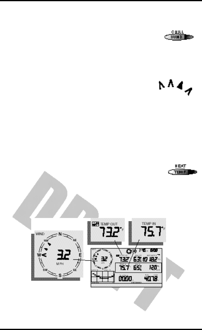
Wind Speed and Direction
• Wind Speed
Press the WIND / CHILL key to select the wind speed
field. Wind speed may be displayed in miles per hour
(mph), kilometers per hour (kph), meters per second (m/
s), and knots (knots).
• Wind Direction
The solid arrow within the wind rose graphically displays
the current wind direction. The arrow caps display the
last six 10-minute dominant wind directions. The console
measures the dominant wind direction every ten minutes,
discarding the oldest measurement and entering the new
measurement at the top of the list. If the dominant wind
direction does not vary over a 60 minute period, only one
arrow cap will be displayed.
To activate a digital readout of the wind direction, press the WIND / CHILL
key again. The digital wind direction is displayed in degrees. See “Wind” on
page 47.
Temperature
• Outside Temperature
Press the TEMP / HEAT key to select the outside temperature
field. Note that the graph icon appears next to the data field.
Temperature data may be displayed in both degrees Fahren-
heit (ºF) and Centigrade (ºC). See “Temperature” on page 47.
• Inside Temperature
Press the TEMP / HEAT key again to activate the inside temperature field.
Again, the graph icon appears next to the data field.
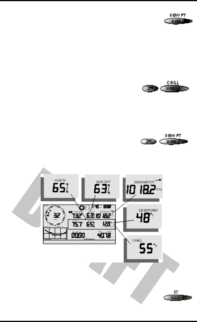
Humidity
Chapter 3
Page 28 Vantage Pro Console Manual
Press the HUM / DEW PT key to select the outside humidity
field.
Press the HUM / DEW PT key again to activate the inside
humidity field.
Humidity is displayed in percent relative humidity. See “Dew-Point” on
page 50.
Wind Chill
• Current Wind Chill
Press and release the 2ND key, then press the WIND
/ CHILL key to select the Wind Chill field.
Wind Chill is displayed in either degrees Fahrenheit
(ºF) or Centigrade (ºC). See “Apparent Temperature
Measures” on page 47.
Dew Point
• Current Dew Point
Press and release the 2ND key, then press the
HUM / DEW PT key to select the Dew Point
field.
Dew Point is displayed in either degrees Farenheit (ºF) or Centigrade (ºC). See
“Dew-Point” on page 50.
Barometric Pressure
• Current Barometric Pressure
Press the BAR / ET key to select the barometric pressure.
Humidity, Pressure, Dew Point,
& Wind Chill
Current Weather Mode
Vantage Pro Console Manual Page 29
Barometric pressure may be displayed in inches (in), millimeters (mm), milli-
bars (mb) or hectoPascals (hPa). See “Barometric Pressure” on page 50.
• Pressure Trend Arrow
The Barometric Trend Arrow depicts the current barometric trend, measured
over the last 3 hours. The trend arrow is always displayed (unless less than
three hours of pressure data is available), whether the barometric pressure is
selected or not.
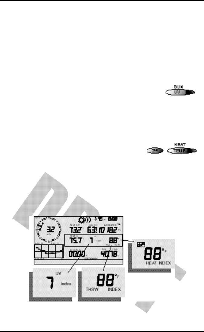
UV (Ultraviolet Radiation)
• Current UV
Press the UV / SUN key to display the current UV read-
ing as an index. Press again to see MEDS.
UV may be displayed as an index (1-7) or in MEDS. See
“UV (Ultra Violet) Radiation” on page 51.
Heat Indices
• Heat Index
Press and release the 2ND key, then press the
TEMP / HEAT key to display the Heat Index. See
“Apparent Temperature Measures” on page 47.
• THSW Index
If you have installed the optional Solar Radiation
Sensor, repeat the sequence one more time to display the THSW (Temperature -
Humidity - Sun - Wind Index). See “Apparent Temperature Measures” on
page 47.
Both heat indices appear in the same place on the screen and may be displayed,
like temperature and wind chill, as either degrees Fahrenheit (ºF) or Centigrade
(ºC).
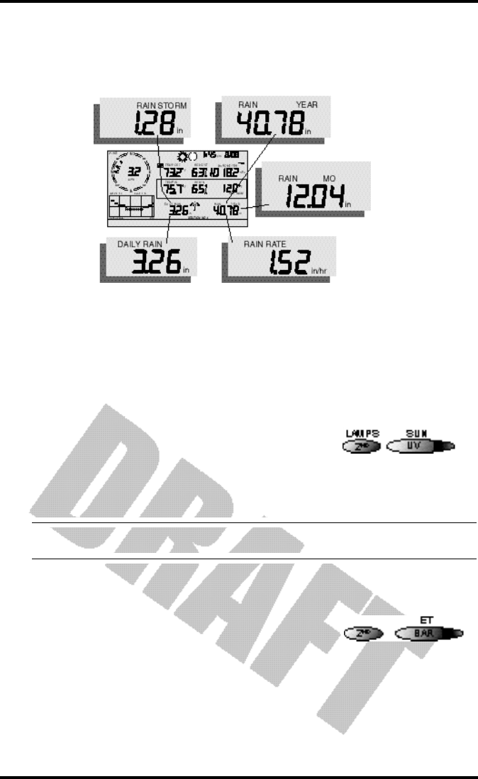
Rain “Year”, Rain “Month”, and Rain Rate

Chapter 3
Page 30 Vantage Pro Console Manual
• Rain Rate
Press the RAINYR / RAINDAY key to display the current rain rate.
Rain Rate may be displayed as either inches per hour (in/hr) or millimeters per
hour (mm/hr). If there has been rain in the last 15 minutes, the total will be dis-
played in the ticker.
• Month-to-date precipitation
Press the RAINYR / RAINDAY again to select the month-to-date precipitation
record. Monthly rain displays the precipitation accumulated since the calendar
month began. Month-to-date precipitation is displayed in inches (in) or milli-
meters (mm).
• Year-to-date precipitation
Press the RAINYR / RAINDAY key a third time to display
the year-to-date precipitation record. Yearly rain displays
the precipitation accumulated since the 1st of the month
you’ve chosen in Setup Mode (See “Setup Mode - Screen
13: Rain Season” on page 26.) Year-to-date precipitation is displayed in inches
(in) or millimeters (mm).
Note: The“Year-to-date” and “Month-to-date” registers record precipitation accumulation for 1 year and 1
month respectively; however, you may start each counting period whenever you wish.
“Daily” and “Storm” Rain
• “Daily” Rain
Press and release the 2ND key, then press the
RAINYR / RAINDAY key. Daily Rain displays the
rain accumulated since 12 midnight. Any rain
accumulated in the last 24 hours will be displayed
in the ticker.
Current Weather Mode
Vantage Pro Console Manual Page 31
• Rain “Storm”
Rain “Storm” displays the rain total for the last rain event occurring at least 24
hours from any previous rain event. Repeat the above sequence: press and
release the 2ND key, then press the RAINYR / RAINDAY key.
All rain accumulation may be displayed as either millimeters (mm) or inches
(in). See “Rainfall” on page 50.
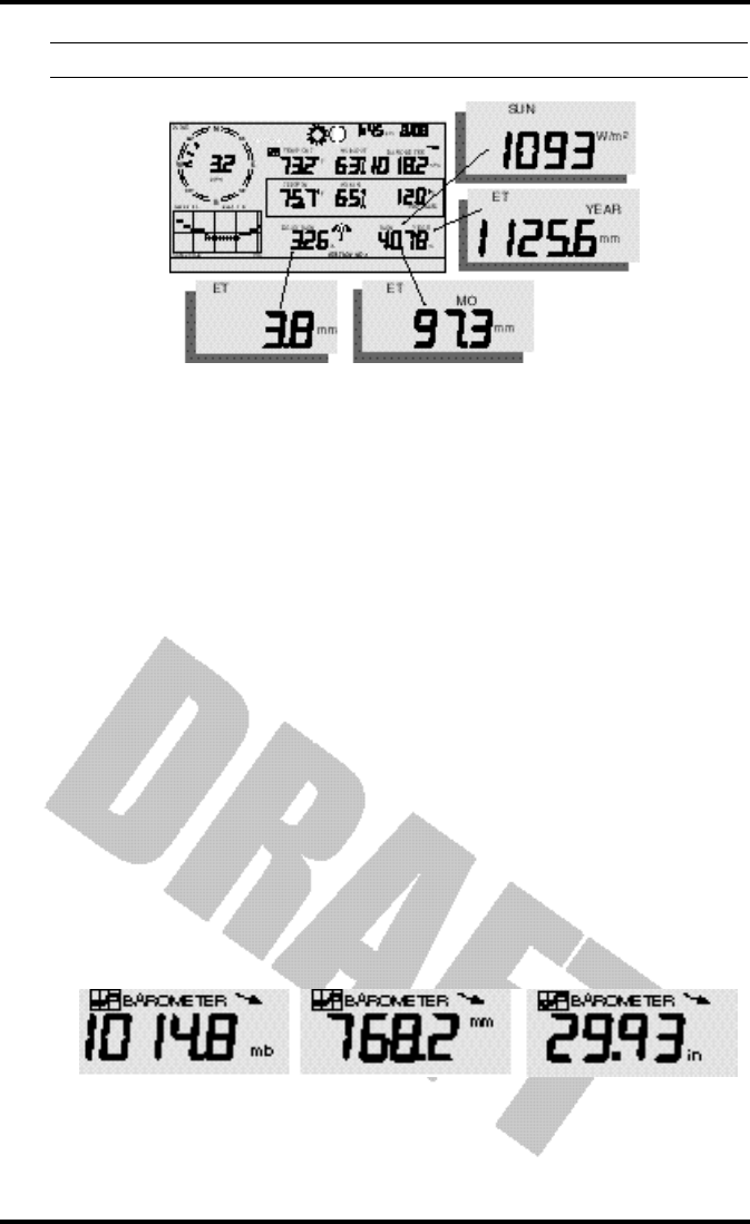
Solar Radiation
• Current Solar Radiation
Press and release the 2ND key, then press the UV /
SUN key to display the current solar radiation
reading.
Solar radiation is displayed as Watts per square
meter (W/m2). See “Solar Radiation” on page 51.
Note: To display solar radiation readings, you must have installed the optional Solar Radiation sensor. (See
“Optional Sensors” on page 9)
ET (Evapotranspiration)
• Current ET
Press and release the 2ND key, then press the BAR /
ET key to display the current evapotranspiration
reading. See “EvapoTranspiration (ET)” on page 54.
• Monthly ET
Repeat the sequence (i.e. Press and release the 2ND key, then press the BAR /
ET key) to display Monthly ET.
• Yearly ET
Repeat the sequence a third time to display the ET reading since January 1st of
the current year.
Daily Rain, Rain Storm, Rain Year, Rain Month, & Rain Rate
Chapter 3
Page 32 Vantage Pro Console Manual
Note: To display ET readings, you must install the optional Solar Radiation sensor.
Selecting Units
Most weather variables may be displayed in at least two different units, typi-
cally the English and Metric systems, although some variables feature more
possibilities. Barometric pressure, for example, may be displayed in millibars,
millimeters, inches, or hectoPascals.
You may change the units display at any time.
To change the units for any variable:
1. Activate the variable using the keypress sequences described above. (See “Activating
Weather Variables” on page 26.)
2. Press and release the 2nd key.
3. Press the Graph / Units key.
The selected variable’s units will change. Repeat steps 2 and 3 until the
desired units appear.
For example, to select Barometric pressure units, activate the Barometric
presure by pushing BAR. Next, press and release the 2nd key, then press the
Graph / Units key. The units field will display millibars, millimeters, inches, or
hectoPascals. Repeating these steps cycles through all four selections. Stop
when the the desired unit appears.
Current
ET, ET Month, ET Year, & Solar Radiation
Barometric Pressure: millibars (mb), millimeters (mm) and inches (in)

Highs and Lows Mode
Vantage Pro Console Manual Page 33
HIG H SA N D LO W S MO D E
The Vantage Pro records highs and lows for many weather conditions over
three different periods: days, months, and years. Except for Yearly Rainfall, all
high / low registers are cleared automatically at the end of each period (day:
midnight; month: month-end midnight; year: year-end midnight) by the sta-
tion. You may enter the month that you would like the Yearly Rainfall accumu-
lation to clear. The Yearly Rainfall will clear on the first day of the month you
choose.
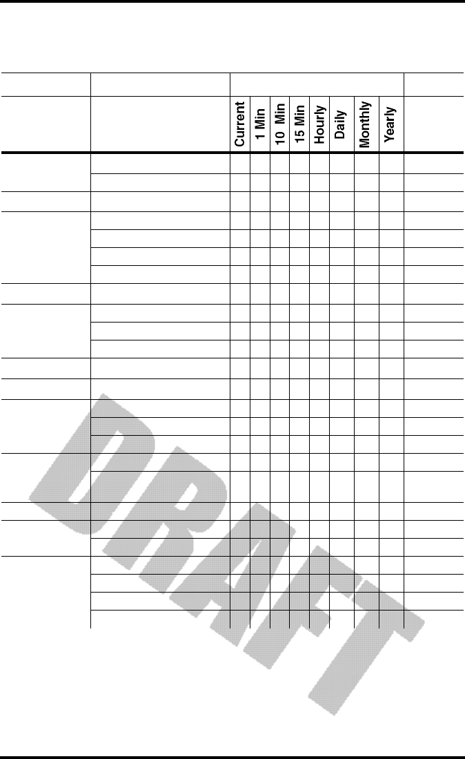
The table below summarizes the highs and lows stored by the Vantage Pro.
§ Requires optional Solar Radiation Sensor
^ Requires optional UV radiation sensor
† Requires Soil Moisture sensor
‡ Requires Leaf Wetness sensor
Accessing Highs and Lows
• Press the HI/LOW button to enter the Highs and Lows mode.
The "DAY" and "HIGHS" icons will light and the station displays the highs
for all visible fields.
CONDITION HIGH LOW
DAY
TIME &
DATE
MONTH YEAR ADDITIONAL
INFORMATION
Outside Temperature Yes Yes Yes Yes Yes
Inside Temperature Yes Yes Yes Yes Yes
Outside Humidity Yes Yes Yes Yes Yes
Inside Humidity Yes Yes Yes Yes Yes
Heat Index Yes Yes Yes Yes
Temp / Hum / Wind / Sun Index Yes Yes Yes Yes §
Wind Chill Yes Yes Yes Yes
Wind Speed Yes Yes Yes Yes Direction of High
Rainfall Rate Yes Yes Yes Yes
Daily Rain Total Total Total
UV Index Yes Yes Yes Yes ^
Solar Radiation Yes Yes Yes Yes §
Dew Point Yes Yes Yes Yes Yes
Evapotranspiration Total Total Total §,‡
Soil Moisture Yes Yes Yes Yes Yes †
Leaf Wetness Yes Yes Yes Yes Yes ‡

Chapter 3
Page 34 Vantage Pro Console Manual
•Use the "+" and "-" arrow keys to scrolll between Day Highs, Day Lows, Month Highs,
Month Lows, Year Highs and Year Lows.
The DAY, MONTH, YEAR and HIGH or LOW icons will light to show you
what High/Low screen you’ve selected. See “Graph and Hi / Low mode
settings” on page 19.
•Use the LEFT and RIGHT arrow keys to scroll back and forth through the last 24 days.
Pressing the LEFT arrow button moves you to the previous day’s highs -
the date field will change to show you. Each time you press the LEFT
arrow, you’ll move another day backward. The 24 dots in the graph field
also represent each of the last 24 days; the rightmost dot is today. As you
move back (or forward, with the RIGHT arrow key), the “day dot” will
flash to show you what day you’re looking at.
•Use the function keys to choose any particular variable. The time of the high (or low)
for that field will appear in the upper right of the screen.
Exit Highs and Lows screen
•To exit the Highs and Lows mode, simply press and release the DONE key. The console
display will switch to the Current Weather mode.

Alarms Mode
Vantage Pro Console Manual Page 35
AL A R M S MO D E
The Vantage Pro features more than 30 alarms that can be programmed to
sound whenever a reading exceeds a set value. With the exception of baromet-
ric pressure and time, all alarms sound when a reading reaches the alarm
threshold. For example, if the high outside temperature alarm threshold is set
at 65 ºF, the alarm will sound when the temperature rises to 65.0 ºF.
In addition, the alarm bell icon will blink repeatedly. If you are using an AC
power adapter with your console, the alarm will continue to ring until you
clear the alarm or until the temperature again drops below the threshold. If you
are running on battery power, the alarm will beep for XX minutes only; how-
ever, the bell icon will continue to blink until you clear the alarm or the temper-
ature drops below the threshold.
Low alarms work the same way. For example. if the wind chill threshold is set
for 30 ºF, the alarm begins sounding when the temperature drops to 30.0 º and
will continue flashing until the temperature again rises above 30.0º.
Note: See Table “Vantage Pro Console Graphs & Alarms” on page 37 for a listing of the Vantage Pro Con-
sole’s alarms.
Three special alarms
ETo (Evapotranspiration)
ETo is updated only once an hour, on the hour. If during a given hour the ETo
Value exceeds the alarm threshold, the ETo alarm sounds at the end of that
hour. This is true for daily, monthly, and yearly ETo alarms. You must have the
optional Solar Radiation Sensor to use this alarm. See “EvapoTranspiration
(ET)” on page 54 for a description of this variable.
Barometric Pressure
The Vantage Pro allows you to set two barometric pressure alarms: a “rise”
alarm and a “fall” alarm. You may select any rate of change per hour between
0.00 and 0.99 Hg; the Vantage Pro’s alarm will sound if the rate of change (in
either direction) exceeds your threshold.
Time
The time alarm is a standard "alarm clock" type of alarm. It will sound for one
minute.
Setting Alarms
1. Press the 2nd and the STATION/ALARM button to enter alarm mode.
The ALARM and HIGHS icons will appear. If you want to set LOW alarms,
press 2nd and STATION/ALARM. Then press the HI/LOW button. The
LOWS icon will appear.

Chapter 3
Page 36 Vantage Pro Console Manual
2. Select any weather variable available.
Use the arrow keys to select variables currently displayed, or use the key-
press sequences. (See “Activating Weather Variables” on page 26 for review.)
3. Press 2nd and DONE/SET.
The rightmost digit in the variable field will begin blinking. Use the up and
down arrow keys to change the digit. Use the left and right arrow keys to
move between digits.
4. When you’ve keyed in the threshold value you want, press the DONE/SET key again.
You’re still in the alarm mode, so choose any other variable for which you’d
like to set a threshold.
5. If you’re finished setting alarms, press DONE/SET again and the console will return to
current weather mode.
Setting the Time Alarm
1. To set the time alarm, enter the alarm mode as described above.
2. Press Time, then 2nd and DONE/SET.
The time field will begin blinking. Set the time and date for the alarm.
Clearing Alarms
Clearing an alarm is easy.
• If an alarm is sounding, press 2ND and then hold the HI/LOW / CLEAR key until the
ringing stops (~ four seconds).
• To clear a set alarm,
1. enter alarm mode as described above.
2. Select the variable alarm you wish to clear, either by pressing the key, e.g. UV,
or using the arrow keys.
You must use the keypress sequence to activate the variable if the vari-
able is not displayed.
• Press and hold clear.
The threshold value will blink. When the value changes to all dashes,
you have cleared the value.
Alarms Mode
Vantage Pro Console Manual Page 37
Table 2: Vantage Pro Console Graphs & Alarms
Graphs Alarms
Barometric
Pressure Reading C C C H,L H,L
Trend ❶ ❷
ET§Evapotranspiration T T T T T ❸
Humidity &
Dewpoint
Inside Humidity C C H,L H,L H,L
Outside Humidity C C H,L H,L H,L
Dew Point C C H,L H,L H,L
Extra Humidity H,L
Leaf Wetness*Leaf Wetness C C H,L H,L H,L
Rainfall
Rain T T T T T T ❹ ❺
Storm ❻
Rain Rate H H H H H H H
Soil MoistureΩSoil Moisture C C H,L H,L H,L
Solar Radiation§Solar Radiation A A H H H
Temperature
Inside Temp C C H,L H,L H,L
Outside Tem C C H,L H,L H,L H,L
Extra Temp H,L
Apparent
Temperature
Heat Index C C H H H
Temp/Hum/Sun/Wind
Index§C C H H H
Time & Date Time Y
UV Radiation‡UV Radiation A A H H H
MED (Minimal Erythemal Dose) T T T ➐
Wind
Wind Speed A A A H H H H ❽
Direction of highwind speed Y Y Y Y
Dominant Wind Direction A A A A
Wind Chill L L L L L

Chapter 3
Page 38 Vantage Pro Console Manual
Legend:
A =Average, H =Highs, L =Lows, T =Totals, Y =Yes, C =Current Reading at end of each period
Additional graph:
■ Storm graph - Graphs last 24 rain storms with start and stop dates.
Additional Alarms:
❶ Storm Warning Alarm - Specify amount of barometer’s fall.
❷ Storm Clearing Alarm - Specify amount of barometer’s rise.
❸ ET Alarm - Specify total amount of ET for the day.
❹ Flash Flood Alarm - Specify total amount of rainfall for current 15 minutes.
❺ 24 Hour Rain Alarm - Specify total amount of rainfall for the current 24 hours.
➏ Storm Alarm - Specify totatl amount of rainfall for current storm.
➐ MED Alarm - Specify daily dose.
❽ 10 Minute Average Wind Speed Alarm - Specify speed.
▲ Current values are shown in the right-most column of graph, and are the most recent records.
All graphed historical values are the last 24 on record.
* Requires wireless Vantage Pro and optional Leaf Wetness Station.
Ω Requires wireless Vantage Pro and optional Soil Moisture Station.
‡ Requires optional UV Sensor
§ Requires optional Solar Radiation Sensor
Table 2: Vantage Pro Console Graphs & Alarms
Graphs Alarms

Graph Mode
Vantage Pro Console Manual Page 39
GR A P H MO D E
The Vantage Pro Console features a powerful graphing facility. Using this
mode, you may view over 100 graphs of different kinds - all without connect-
ing to a personal computer.
Table 2 above details the graphs that the Vantage Pro Console can display. Note
especially that different weather variables may have different graphs available.
(Some graphs require optional sensors. See above for details.)
Entering and Exiting Graph Mode
• Press the “GRAPH” key to enter graph mode
You’ll know you’re in graph mode because only the date field, graph,
graph mode indicator (See “Display Features” on page 19.) and the cur-
rently selected variable will be lit. The rest of the screen will be blank.
• Press the “DONE” key to exit the graph mode
Using and Understanding the Graph Mode’s Features
Although the available graphs vary, depending on what weather variable
you’re plotting, you view each graph the same way.

Chapter 3
Page 40 Vantage Pro Console Manual

Vantage Pro Manual Page 41
TR O U B L E S H O O T I N G
While the Vantage Pro is designed to provide years of trouble-free operation,
occasional problems may arise. If you are having problems with your unit,
please check the following guide before sending the unit in for repair. You will
be able to solve many of the problems yourself. If, after checking this guide,
you are unable to solve the problem, please call the factory at 1-510-732-7814
for further instructions. Please do not return your unit for repair without prior
authorization.
Troubleshooting
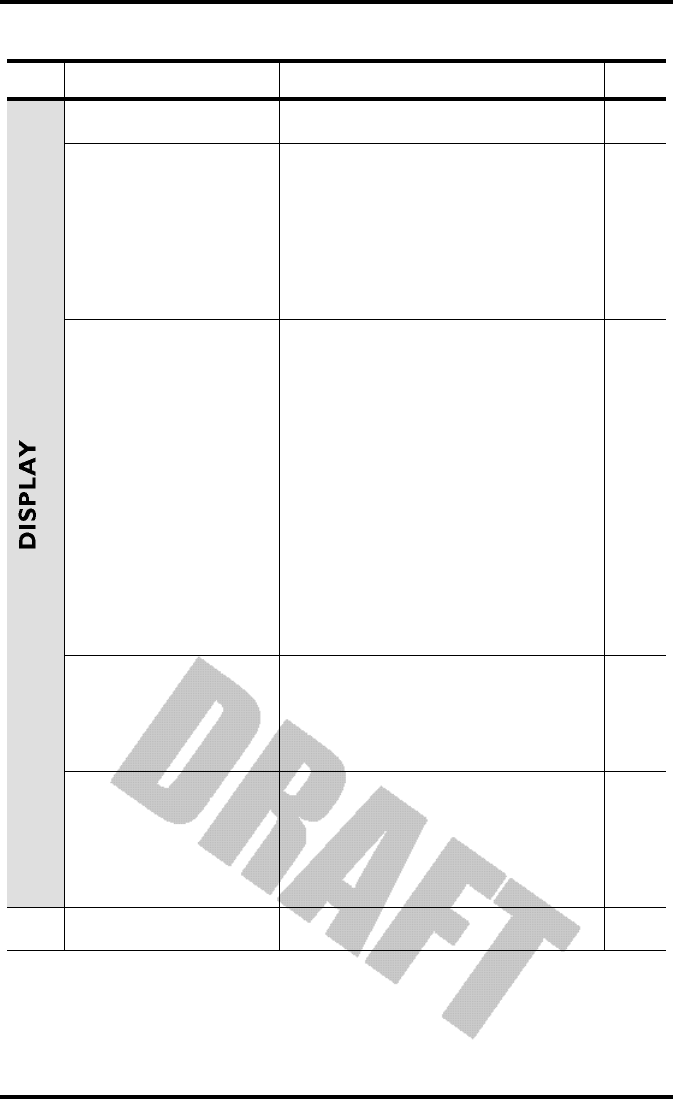
Page 42 Vantage Pro Manual
Problem Solution PG.
Display is blank Unit is not receiving power. Check to be
sure the power adapter has not come
unplugged from the console or outlet.
If power is interrupted, battery may be
installed incorrectly. Check and re-install.
Battery may be run down or old. Replace.
Display shows a series
of dashes in place of
function reading
ISS not plugged in (Cabled Vantage Pro).
Sensors not transmitting. (Wireless Van-
tage Pro) See ISS (or other transmitter)
manual.
Console not receiving. (Wireless) Check
reception.
A reading has exceeded the limits indi-
cated in the specifications table.
For temperature, wind speed, or rainfall:
calibration nmbers may be causing read-
ings to exceed display limits. Check cali-
bration number and adjust if necessary.
Display is sluggish or
computer does not
work at low tempera-
tures
The console, LCD display, and internal
components may not work below 32º F (0º
C). Use the External Temperature sensor in
low-temperature locations and keep the
Vantage Pro console in a warmer location.
Display “locks up” The Vantage Pro console may “lock up” if
there is a power surge. To restore the unit,
remove all power (including battery
backup) and then restore power. If “lock
ups” occur frequently, add a surge sup-
pressor to the power line.
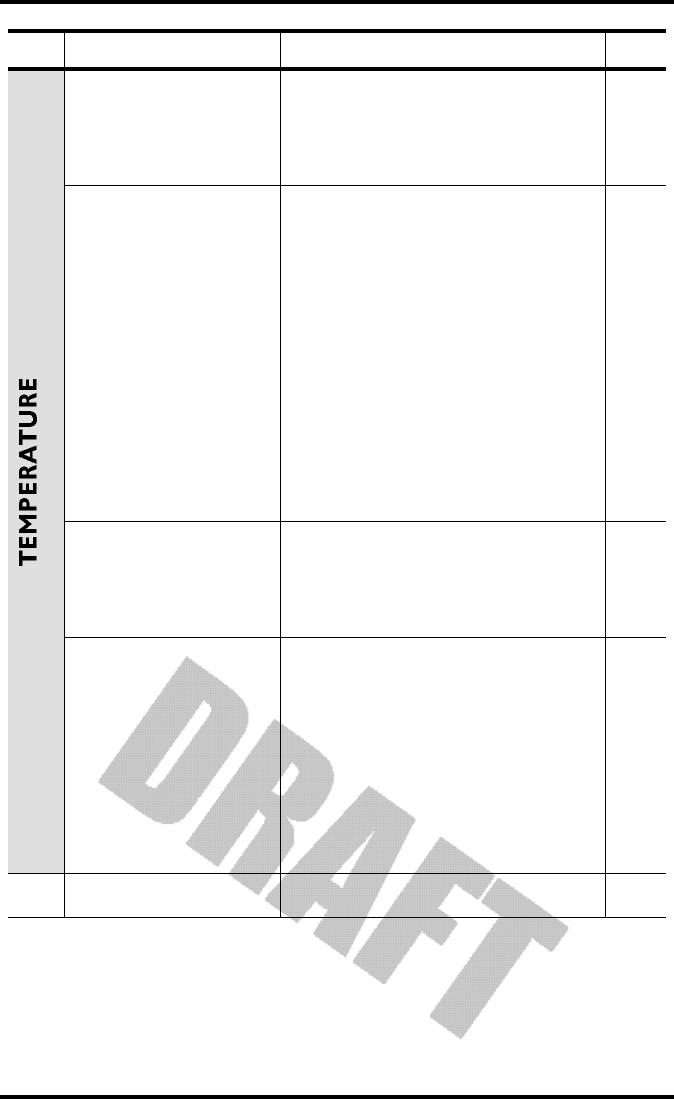
TEMPERATURE
Vantage Pro Manual Page 43
Outside temperature
sensor reading seems
too high
Check calibration number and adjust if
necessary.
ISS may need to be relocated. See ISS (or
other transmitter) manual
Inside temperature
sensor reading seems
too high
Move the Vantage Pro console (or other
temp sensor if you have installed addi-
tional wireless temperature sensors) out of
direct sunlight.
Make sure that the console or sensor is not
in contact with an exterior wall that heats
up in sunlight or when outside tempera-
ture rises.
Make sure the console or sensor is not near
a heater or other internal heat source
(lamps, appliances, etc.).
Check calibration number and adjust if
necessary.
Outside temperature
seems too low
Check calibration number and adjust if
necessary.
Sprinklers may be hitting the ISS radiaion
shield. Relocate. See ISS manual.
Inside temperature
sensor reading seems
too low
Make sure the the console or other tem-
perature sensor is not in contact with an
exterior wall that cools down when out-
side temperature drops.
Make sure the console or other tempera-
ture sensor is not near an air conditoning
vent.
Check calibration number and adjust if
necessary.
Problem Solution PG.
Troubleshooting
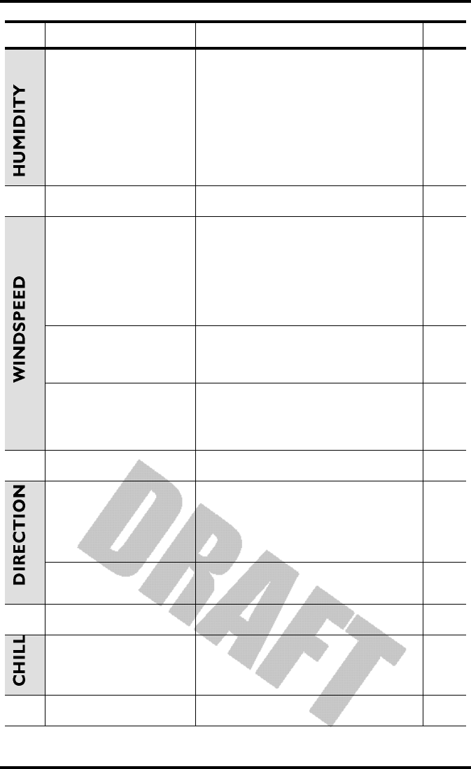
Page 44 Vantage Pro Manual
Inside humidity seems
too high or too low
Make sure the Vantage Pro console is not
near a humidifier or de-humidifier.
Check calibration number and adjust if
necessary.
If inside humidity, along with inside tem-
perature, is too high, see also “inside
temp” above.
Wind speed reading
seems lower than
expected
Check installation by spinning wind cups.
If you get a reading, the wind cups are
installed correctly. They should spin more
freely after an initial break-in period of
one or two weeks.
Check ISS location.
Wind speed reads 0
either all the time or
intermittently
The problem may be with the anemome-
ter. Call factory for return authorization.
Wind speed reading
seems too high or too
low.
Check calibration number and adjust if
necessary.
Check ISS location.
Wind direction reading
is dashed out
Transmission problem.
If these steps do not reveal the problem,
the anemometer may be faulty. Call the
factory for return authorization.
Wind direction always
says North
ISS problem, especially if outside tempera-
ture is dashed out as well.
Wind chill reading
seems too high or too
low
Check calibration number for temperature
and wind speed. Adjust if necessary.
Problem Solution PG.

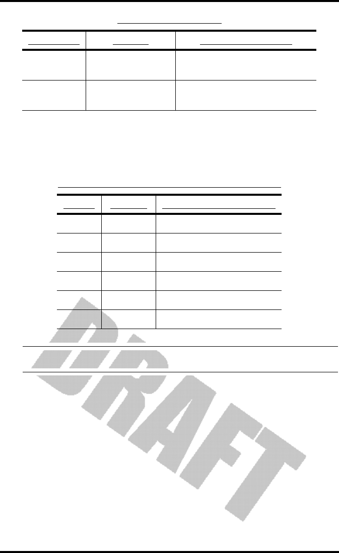
Rain
Vantage Pro Manual Page 45
No rain readings Make sure cable-tie is removed from rain
collector. See ISS manual.
Problem Solution PG.

Troubleshooting
Page 46 Vantage Pro Manual

Vantage Pro Manual Page 47
AP P E N D I X:
WE A T H E RDA T A
WE A T H E RCO N D IT IO N SME A S U R E D/CA L C U L A T E D
This section outlines each of the weather conditions measured/calculated by
the Vantage Pro. Each section includes a brief discussion of the weather condi-
tion and a listing of the various ways in which the unit displays or stores that
condition. Be aware that some of the weather conditions require an optional
sensor in order to measure/calculate a value (see “Optional Sensors” on
page 9).
Wind
The Vantage Pro measures wind speed and direction from which it’s blowing.
The 10 minute average wind speed is displayed in the weather ticker when
wind is selected with the graph icon.
Temperature
The Vantage Pro uses the primary temperature sensor to measure the outside
air temperature. A second temperature sensor in the console measures the
inside air temperature. Additional temperature sensors (available only with
wireless Vantage Pro) can be used to measure temperature in other locations.
You may use these extra sensors to measure whatever auxiliary temperature
you see fit (including water temperature).
Apparent Temperature Measures
The Vantage Pro calculates three apparent temperature readings: wind chill,
heat index, and the temperature/humidity/sun/wind index (THSW Index).

Appendix: Weather Data
Page 48 Vantage Pro Manual
• Wind chill
Wind chill takes into account how the speed of the wind affects our per-
ception of the air temperature. Our bodies warm the surrounding air
molecules by transferring heat from the skin. If there’s no air movement,
this “insulating layer” of warm air molecules stays next to the body and
offers some protection from cooler air molecules. However, wind sweeps
that comfy warm air surrounding the body away. The faster the wind
blows, the faster heat is carried away and the colder you feel. Above 91 F,
wind movement has no effect on the apparent temperature, so wind chill
= the outside temperature.
• Heat Index
The Heat Index uses the temperature and the relative humidity to deter-
mine how hot the air actually “feels.” When humidity is low, the appar-
ent temperature will be lower than the air temperature, since
perspiration evaporates rapidly to cool the body. However, when
humidity is high (i.e., the air is saturated with water vapor) the apparent
temperature “feels” higher than the actual air temperature, because per-
spiration evaporates more slowly.
Note: Vantage Pro measures Heat Index only when the air temperature is above 57˚ F (14˚ C), because
it’s insignificant at lower temperatures. (Below 57˚, Heat Index = the air temperature.) The Heat
Index is not calculated above 135˚ F (52˚ C), because calculation factors are not available.
• THSW (Temperature - Humidity - Sun - Wind)
Finally, like Heat Index, the THSW Index uses humidity and tempera-
ture to calculate an apparent temperature. In addition, THSW incorpo-
rates the heating effects of direct solar radiation and the cooling effects of
wind on our perception of temperature.
Note: The Vantage Pro displays THSW only if you have the optional Solar Radiation sensor.

Weather Conditions Measured/Calculated
Vantage Pro Manual Page 49
Relative Humidity
Humidity itself simply refers to the amount of water vapor in the air. However,
the amount of water vapor which the air can contain varies with air tempera-
ture and pressure. Relative humidity takes into account these factors and offers
a humidity reading which reflects the amount of water vapor in the air as a per-
centage of the amount the air is capable of holding. Relative humidity, there-
fore, is not actually a measure of the amount of water vapor in the air, but a
ratio of the air’s water vapor content to its capacity.
It is important to realize that relative humidity changes with temperature, pres-
sure, and water vapor content. A parcel of air with a capacity for 10 g of water
vapor which contains 4 g of water vapor, the relative humidity would be 40%.
Adding 2 g more water vapor (for a total of 6 g) would change the humidity to
60%. If that same parcel of air is then warmed so that it has a capacity for 20 g
of water vapor, the relative humidity drops to 30% even though water vapor
content does not change.
Relative humidity is an important factor in determining the amount of evapo-
ration from plants and wet surfaces since warm air with low humidity has a
large capacity for extra water vapor.
TABLE A1: HEAT AND COLD EFFECTS

Appendix: Weather Data
Page 50 Vantage Pro Manual
Dew-Point
Dew-point is the temperature to which air must be cooled for saturation (100%
relative humidity) to occur, providing there is no change in water content. The
dew-point is an important measurement used to predict the formation of dew,
frost, and fog. If dew-point and temperature are close together in the late after-
noon when the air begins to turn colder, fog is likely during the night. Dew-
point is also a good indicator of the air’s actual water vapor content (as
opposed to relative humidity). High dew-point indicates high vapor content;
low dew-point indicates low vapor content. In addition a high dew-point indi-
cates a better chance of rain and severe thunderstorms. You can even use dew-
point to predict the minimum overnight temperature. Provided no new fronts
are expected overnight and the afternoon Relative Humidity ≥ 50%, the after-
noon’s dew-point gives you an idea of what minimum temperature to expect
overnight, since the air is not likely to get colder than the dew-point anytime
during the night.
Rainfall
The Vantage Pro provides four separate registers for tracking rainfall totals:
“rain storm”, “daily rain”, “monthly rain”, and “yearly rain”. The Vantage Pro
also calculates the rate of rainfall by measuring the interval of time between
each .01” or .254 mm rainfall increment.
Barometric Pressure
The weight of the air that makes up our atmosphere exerts a pressure on the
surface of the earth. This pressure is known as atmospheric pressure. Gener-
ally, the more air above an area, the higher the atmospheric pressure, this, in
turn, means that atmospheric pressure changes with altitude. For example,
atmospheric pressure is greater at sea-level than on a mountaintop. To compen-
sate for this difference and facilitate comparison between locations with differ-
ent altitudes, atmospheric pressure is generally adjusted to the equivalent sea-
level pressure. This adjusted pressure is known as barometric pressure. In real-
ity, the Vantage Pro measures atmospheric pressure. When you enter your loca-
tion’s altitude in Setup Mode, the Vantage Pro stores the necessary offset value
to consistently translate atmospheric pressure into barometric pressure.
Barometric pressure also changes with local weather conditions, making baro-
metric pressure an extremely important and useful weather forecasting tool.
High pressure zones are generally associated with fair weather while low pres-
sure zones are generally associated with poor weather. For forecasting pur-
poses, however, the absolute barometric pressure value is generally less
important than the change in barometric pressure. In general, rising pressure
indicates improving weather conditions while falling pressure indicates deteri-
orating weather conditions.
Note: The following variables require optional sensors and / or stations. See “Optional Sensors” starting on
page 9.

Weather Conditions Measured/Calculated
Vantage Pro Manual Page 51
Solar Radiation
What we call “current solar radiation” is technically known as Global Solar
Radiation, a measure of the intensity of the sun’s radiation reaching a horizon-
tal surface. This irradiance includes both the direct component from the sun
and the reflected component from the rest of the sky. The solar radiation read-
ing gives a measure of the amount of solar radiation hitting the solar radiation
sensor at any given time, expressed in Watts /sq. m (W/m2).
Note: The Vantage Pro measures energy received in the spectral band between 400 and 1100 nm.
UV (Ultra Violet) Radiation
Energy from the sun reaches the earth as visible, infrared, and ultraviolet (UV)
rays. Exposure to UV rays can cause numerous health problems, such as sun-
burn, skin cancer, skin aging, and cataracts, and can suppress the immune sys-
tem. The Vantage Pro can help analyze the changing levels of UV radiation and
can advise of situations where exposure is particularly unacceptable.
!! CAUTION: Be aware, however, that the Vantage Pro’s UV readings do not take into account UV reflected
off snow, sand, or water, which can significantly increase the amount of UV to which you are exposed.
Nor does the Vantage Pro take into account the dangers of prolonged exposure to UV radiation. The
readings do not suggest that any amount of exposure is safe or healthful. Do not use the Vantage
Pro to determine the amount of UV radiation to which you expose yourself . Scientific
evidence suggests that UV exposure should be avoided and that even low UV doses
can be harmful.
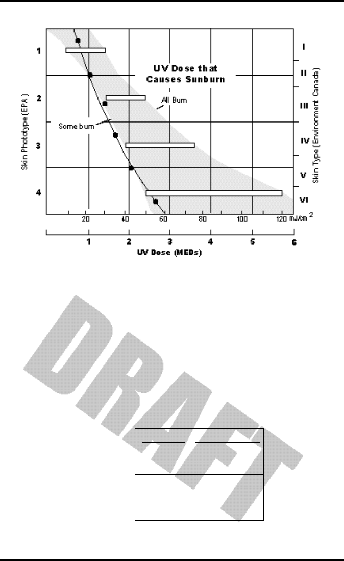
The Vantage Pro displays UV readings in two scales: MEDs and UV Index.
MED stands for Minimum Erythemal Dose, defined as the amount of sunlight
exposure necessary to induce a barely perceptible redness of the skin within 24
hours after sun exposure. In other words, exposure to 1 MED will result in a
reddening of the skin. Because different skin types burn at different rates, 1
MED for persons with very dark skin is different from 1 MED for persons with
very light skin.
Both the U.S. Environmental Protection Agency (EPA) and Environment Can-
ada have developed skin type categories correlating characteristics of skin with
rates of sunburn. Tables 3a and 3b below list these skin types.
TABLE A2: EPA SKIN PHOTOTYPES
SKIN PHOTOTYPE SKIN COLOR TANNING & SUNBURN HISTORY
1 - Never tans,
always burns
Pale or milky white; alabaster Develops red sunburn; painful swelling, skin peels
2 - Sometimes tans,
usually burns
Very light brown; sometimes
freckles
Usually burns, pinkish or red coloring appears;
can gradually develop light brown tan
Appendix: Weather Data
Page 52 Vantage Pro Manual
T. B. Fitpatrick of the Harvard Medical School developed a categorization of
skin types 1 through 6 which were adopted by Environment Canada. These
skin types are detailed in Table 3b below.
Note: More about the Fitzpatrick Skin Types is available in: Fitzpatrick TB. Editorial: the validity and prac-
ticality of sun-reactive skin types I through VI. Arch Dermatol 1988; 124:869-871
3 - Usually tans,
sometimes burns
Light tan; brown, or olive;
distinctly pigmented
Rarely burns; shows moderately rapid tanning re-
sponse
4 - Always tans;
rarely burns
Brown, dark brown, or black Rarely burns; shows very rapid tanning response
TABLE A3: ENVIRONMENT CANADA SKIN TYPES AND REACTION TO THE SUN
SKIN TYPE SKIN COLOR HISTORY OF TANNING & SUNBURNING
I White Always burns easily, never tans
II White Always burns easily, tans minimally
III Light Brown Burns moderately, tans gradually
IV Moderate Brown Burns minimally, tans well
V Dark Brown Burns rarely, tans profusely
VI Black Never burns, deep pigmentation
TABLE A2: EPA SKIN PHOTOTYPES
SKIN PHOTOTYPE SKIN COLOR TANNING & SUNBURN HISTORY
Weather Conditions Measured/Calculated
Vantage Pro Manual Page 53
Vantage Pro can also display UV Index, an intensity measurement first defined
by Environment Canada and since been adopted by the World Meteorological
Organization. UV Index assigns a number between 0 and 16 to the current UV
intensity. The US EPA categorizes the Index values as shown below. The lower
the number, the lower the danger of sunburn. The Index value published by
the U.S. National Weather Service is a forecast of the next day’s noontime UV
intensity. The Index value displayed by the Vantage Pro is the result of a real-
time measurement.
TABLE A4: UV INDEX AND EXPOSURE CATEGORY
INDEX VALUES EXPOSURE CATEGORY
0 - 2 Minimal
3 - 4 Low
5 - 6 Moderate
7 - 9 High
10+ Very High
UV Dose and Sunburn - Use this plot to estimate the MED dose leading to sunburn. A person
with Type II (Environment Canada) skin type might choose 0.75 MED as the maximum for the
day; in contrast, a person with Type V (Environment Canada) Skin Type might consider 2.5
MEDs a reasonable dose for the day. NOTE: the Vantage Pro assumes a Fitzpatrick (Environ-
ment Canada) Skin Type of II.

Appendix: Weather Data
Page 54 Vantage Pro Manual
EvapoTranspiration (ET)
EvapoTranspiration (ET) is a measurement of the amount of water vapor
returned to the air in a given area. It combines the amount of water vapor
returned through evaporation (from wet vegetation surfaces and the stoma of
leaves) with the amount of water vapor returned through transpiration (exhal-
ing of moisture through plant skin) to arrive at a total. Effectively, ETo is the
opposite of rainfall, and it is expressed in the same units of measure (Inches,
millimeters).
The Vantage Pro uses air temperature, relative humidity, wind run1, and solar
radiation data to estimate ET. (ET is calculated once an hour on the hour.)
Please note that calculating ET requires the optional solar radiation sensor. (See
“Optional Sensors” on page 9.)
Leaf Wetness
Leaf wetness (see “Optional Sensors” on page 9) provides an indication of
whether the surface of foliage in the area is wet or dry by indicating how wet
the surface of the sensor is. The leaf wetness reading ranges from 0 (dry) to 15.
Note: Leaf Wetness is only available with the wireless Vantage Pro and the optional Leaf Wetness station.
Soil Moisture
Soil Moisture, as the name suggests, is a measure of the moisture content of the
soil. Soil moisture is measured on a scale of 0 to 200 centibars, and can help
choose times to water crops. The soil moisture sensor measures the vacuum
created in the soil by the lack of moisture. A high soil moisture reading indi-
cates dryer soil; a lower soil moisture reading means wetter soil.
Note: Soil Moisture is only available with the wireless Vantage Pro with the optional Soil Moisture station.
Time
The Vantage Pro has a clock and a calendar for tracking time and date. The cal-
endar automatically adjusts during leap years, providing you have entered the
correct year in the Setup Mode.
1. Wind run is a measurement of the “amount” of wind passing a given point during a specific
amount of time. It’s expressed as either “miles of wind” or “kilometers of wind” and is calculated
by summing wind speed and multiplying by the time of the measurement period. For example, if
the wind blew at an absolutely steady 10 MPH for 12 hours, you would have 120 miles of wind
run (speed x time = 10 MPH x 12 Hours = 120 miles.
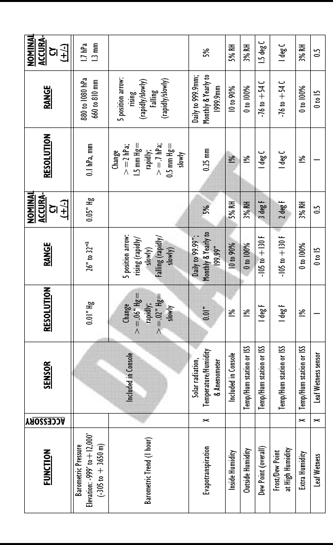
Page 55 Vantage Pro Manual
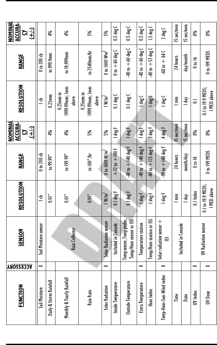
Page 56 Vantage Pro Manual
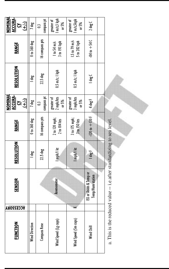
Page 57 Vantage Pro Manual

Page 58 Vantage Pro Manual

Vantage Pro Manual Page 59
RE P A I R &
WA R R A N T Y
I N F O R M A T I O N
ON E YE A R LIM IT E DWA R R A N T Y
For details on Davis’ warranty policy, please refer to the Maintenance, Service,
and Repair Information brochure included with your station.
QU E S T I O N S? CA L L T H E DA V IS SE R V I C ECE N T E R
If you have any questions about our products, please call our Service Center at
1-510-732-7814. We'll be glad to help. Most questions can be answered while
you're on the phone. Sorry, we’re unable to accept collect calls.

Repair & Warranty information
Page 60 Vantage Pro Manual
FCC P A R T 15 CL A S S B R E G I S T R A T IO NWA R N I N G
This equipment has been tested and found to comply with the limits for a Class
B digital device, pursuant to Part 15 of the FCC Rules. These limits are
designed to provide reasonable protection against harmful interference in a
residential installation. This equipment generates, uses, and can radiate radio
frequency energy and, if not installed and used in accordance with the instruc-
tions, may cause harmful interference to radio communications.
However, there is no guarantee that interference will not occur in a particular
installation. If this equipment does cause harmful interference to radio or tele-
vision reception, which can be determined by turning the equipment on and
off, the user is encouraged to try to correct the interference by one or more of
the following measures:
• Reorient or relocate the receiving antenna.
• Increase the separation between the equipment and receiver.
•Connect the equipment into an outlet on a circuit different from that to which the
receiver is connected.
• Consult the dealer or an experienced radio/TV technician for help.
Shielded cables must be used for this equipment to comply with the relevant
FCC regulations. [Previous sentence necessary?] Changes or modifications not
expressly approved in writing by Davis Instruments may void the user's
authority to operate this equipment.
Product Numbers: xxxx, xxxx, xxxx, xxxx
David Instruments Part Number: xxxx-xxx
Vantage Pro Console Manual
Rev. A Manual (10/1/00)
This product complies with the essential protection requirements of
the EC EMC Directive 89/336/EC.
© Davis Instruments Corp. 2000. All rights reserved.