Davis Instruments DWW6310 Weather Station User Manual Manual
Davis Instruments Weather Station Manual
Contents
Manual

Vantage Pro Manual Page 1
WE L C O M ET O T H E VA N T A G EPR O 5
5
Vantage Pro Formats 5
Display & Keyboard 6
Console Modes 6
Multiple stations / Sensors 7
Optional Sensors 7
Optional Accessories 8
Vantage Pro Console Installation 9
Cabled Vantage Pro Console Installation 10
Powering your Vantage Pro 10
Connecting the Cabled Vantage Pro to the
Integrated Sensor Suite (ISS) 10
Wireless Vantage Pro Installation 11
Powering your Wireless Vantage Pro 11
Connecting the Wireless Vantage Pro console
to the Integrated Sensor Suite (ISS) 11
Displaying the Vantage Pro Console 11
Table & Shelf Display 12
Wall Display 12
Using the Vantage Pro Console
13
Chapter 3 13
Keyboard 14
Using the Navigation Keys 14
Display Features 15
Setup Mode 18
Current Weather Mode 18
Activating Weather Variables 18
Wind Speed and Direction 18
Temperature 18
Humidity 19
Wind Chill 19
Dew Point 19
Barometric Pressure 20
UV (Ultraviolet Radiation) 20

Vantage Pro Manual Page 2
Heat Indices 21
Rain “Year”, Rain “Month”, and Rain Rate 21
“Daily” and “Storm” Rain 22
Solar Radiation 22
ET (Evapotranspiration) 23
Selecting Units 24
To change the units for any variable: 24
25
Highs and Lows Mode 25
Alarms Mode 26
Graph Mode 27
Troubleshooting 29
Display 30
TEMPERATURE 31
Humidity 31
Wind Speed 32
Direction 32
chill 32
Repair & Warranty information 33
One Year Limited Warranty 33
Questions? Call the Davis Service Center 33
FCC Part 15 Class B Registration Warning 34
Appendix:
Weather Data 35
Weather Conditions Measured/Calculated 35
EvapoTranspiration (ETo) 36
Temperature 36
Apparent Temperature Measures 36
Wind 38
Solar Radiation 38
UV (Ultra Violet) Radiation 39
Rainfall 40
Barometric Pressure 40
Relative Humidity 41
Dew-Point & Leaf Wetness 41
Time 42

Vantage Pro Manual Page 3
AutoClear 42
42
Specifications 43
Function 43
Display Reading 43
Accuracy 43
Temperature 43

Welcome to the Vantage Pro 5
Page 4 Vantage Pro Console Manual

Vantage Pro Manual Page 5
WE L C O M ET O T H E VA N T A G EPR O
Welcome to Davis Instruments’ Vantage Pro weather station console. The Van-
tage Pro console, part of the comprehensive Vantage Pro system, displays a
wealth of weather information -- up to ten weather variables simultaneously.
The Vantage Pro console is also a powerful weather computer, collecting, stor-
ing, and displaying historical data, including highs and lows, in graphical and
numerical formats.
The Vantage Pro also provides you with a forecast based on the latest meteoro-
logical algorithms. A quick glance at the graphical icons predicts the general
weather trend. A detailed forecast scrolls across the bottom of the screen,
including predicted xxx <!-- what? his and lows, sunny?, tornados?--!>.
Vantage Pro Formats
The Vantage Pro System is available in two formats: Cabled and Wireless.
• Cabled Vantage Pro System
The Cabled Vantage Pro system links the Integrated Sensor Suite (ISS)
sensor array to the console with standard four-conductor cable. The
Standard Vantage Pro system operates on AC power only.
• Wireless Vantage Pro
The wireless Vantage Pro console receives data transmitted by radio
from the solar-powered ISS. Neither the sensor array, nor the console
requires AC power in the wireless format.
1

Page 6 Vantage Pro Console Manual
Display & Keyboard
The Vantage Pro display and keyboard are designed for easy access to the most
important weather information.
The keyboard allows you to interact with the station computer, view current
and historical data, set and clear alarms, change station modes, enter calibra-
tion numbers, set up and view graphs, select sensors, read the forecast, and so
on. To learn more about the keyboard, see “Keyboard” on page 26.
The Large LCD display is your window on current and past environmental
conditions, as well as the place to find the forecast. The console LCD can dis-
play up to 12 <!--what’s the real number? ticker adds many--!> weather vari-
ables at any one time. With the addition of Davis’ programmable weather
ticker, a scrolling alphanumeric display, you can completely personalize the
display to suit your needs, interests, and curiosities. To learn more about the
display’s features, see “Display” on page 21.
Console Modes
The Vantage Pro console operates in five different modes designed to give you
quick and easy access to the information you need:
• Setup
Setup mode is used to enter the time, date, calibration numbers, and
other information required for the processing and display of the weather
data.
• Current Data
Current data is the most common operation mode. In this mode you can
read the current weather information and access any weather data not
currently displayed using the keyboard.
• High / Low
The High and Low mode summaries are accessed using the High/Low
key.
• Alarm
Alarm mode allows the user to set, clear, and review alarm settings.
• Graph
Graph mode allows the user to access the advanced graphing capabili-
ties of the Vantage Pro weather computer.
For more information about using the console, see “Using the Vantage Pro
Console” on page 13 and following sections.

Optional Sensors
Vantage Pro Manual Page 7
Multiple stations / Sensors
The Wireless Vantage Pro system is capable of receiving transmissions from up
to eight different transmitters. See “Optional Sensors” below.
OP T IO N A LSE N S O R S
The Vantage Pro system is extremely flexible. The following optional sensors
enable calculation and measurement of specialized weather information. All
optional sensors are available from your dealer or may be ordered directly
from Davis Instruments. Please be aware that some options are available only-
for wireless units.
• Solar Radiation Sensor
Enables you to measure and display solar irradiance and incident
energy. Also required for calculating Evapotranspiration (see “Evapo-
Transpiration (ETo)” on page 11).
Available for Cabled and Wireless stations. Requires Solar Radiation /
UV mounting shelf. See “Optional Accessories” on page 8.
• Ultraviolet (UV) Radiation Sensor
Enables you to measure and display UV wavelength irradiance.
Required for calculating the burn index.
Available for Cabled and Wireless stations. Requires Solar Radiation /
UV mounting shelf. See “Optional Accessories” on page 8.
Note: The Wireless Vantage Pro console is capable of receiving signals from up to eight separate transmitter
stations, including:
• Wireless Integrated Sensor Suite
A complete sensor package including Rain, Temperature, Humidity,
Wind Speed and Direction, with options for Solar Radiation and UV sen-
sors.
• Wireless Wind Station
Measures and transmits wind speed and wind direction to the console.
• Wireless Rain Station
Measures and transmits rainfall from a remote location to the console.
• Wireless Temperature Station
Measures and transmits air temperature from a remote location to the
console.
• Anemometer Transmitter Kit
Allows separation of anemometer from ISS to capture wind speed and
direction from a remote location.

Page 8 Vantage Pro Console Manual
OP T IO N A LAC C E S S O R IE S
The following accessories, designed for use with the Vantage Pro, are available
from your dealer or may be ordered directly from Davis Instruments.
• VantageLink™ Data Logger & PC Software
Logs data gathered by the Vantage Pro, downloads it to your PC, and
generates reports and graphical displays. Storage interval (1, 5, 10, 15,
30, 60, or 120 minutes) is set by the user. The data logger will store 4, 20,
40, 60, 120, 240, or 480 days worth of data depending on the selected
storage interval. Windows™-compatible software lets you analyze, plot,
print, sort, and summarize the data.
VantageLink™ includes data logger with attached eight foot cable , soft-
ware, and manual. Requires IBM compatible PC running Windows 95 or
98 and one free serial port.
• VantageLink™ 8’ extension cord
Extends the distance between Vantage Pro console and computer an
additional 8 feet.
• Solar Radiation Sensor/ UV Sensor Mounting Shelf
Required for mounting the optional Solar Radiation and / or UV Sen-
sors. The mounting shelf attaches to the ISS.
• ConsoleLink™ Transmitter
The ConsoleLink Transmitter allows a Cabled Vantage Pro console to
broadcast to Wireless Vantage Pro Console Receivers located within 100
to 400 feet (800 line of site).
• AC Power Adapter
Allows Wireless Vantage Pro console to draw power from an AC plug.
Useful if you would like to leave the backlights on all the time, or if you
run more than three remote transmitter stations.
• Cigarette Lighter Power Adapter
Allows the Vantage Pro to draw power from a standard car cigarette
lighter.
Warning: Do not use an older Davis AC Power Adapter or older Davis Cigarette Lighter Adapter.
You will damage the circuitry inside the unit. Use only the Vantage Pro power adapters.
Vantage Pro Manual Page 9
Chapter 2VA N T A G EPR O
CO N S O L E
IN S T A L L A T I O N
The Vantage Pro console is a precision instrument designed to give extremely
accurate readings. As with any precision instrument, care must be used in its
assembly and use. Although installation of the Vantage Pro console is relatively
simple, following the steps outlined in this chapter-- and assembling the Van-
tage Pro correctly from the start-- will ensure that you will enjoy all of its fea-
tures with a minimum of time and effort.

Vantage Pro Console Installation
Page 10 Vantage Pro Manual
CA B L E DVA N T A G EPR O CO N S O LEIN S T A L LA T IO N
The Cabled Vantage Pro is powered by 9-volt DC (direct current) with battery
backup. Power may be supplied by an AC adapter (supplied with Cabled Van-
tage Pro stations), or with the optional 12 to 9-Volt Car/Boat/RV power
adapter. (See “Optional Accessories” on page 8.)
• WARNING: The Vantage Pro system uses power differenly from the way older Davis stations did. Use only
a Davis Vantage Pro 9-volt power converter. Using an older Davis adapter will damage your Vantage Pro!
Powering your Vantage Pro
Because the Cabled Vantage Pro console supplies power to the sensor array
through the connecting cable, you must use the AC power adapter or the
optional Car/Boat/RV adapter to supply primary power. The three C-cell bat-
teries provide backup power and will operate the station for only a few days.
1. Insert the power adapter plug into the jack located on the right side of the console,
then plug the other end of the adapter into an appropriate power outlet.
The Vantage Pro should run through a brief self-test procedure. All the dis-
play segments on the LCD appear and the console will beep<!--number_!>
times.
<!--Don Raime figure here--!>
2. Insert the C-cell battery backup.
Remove the access cover located on the back of the console. Insert 3 C batter-
ies into the battery channel, negative (or flat) terminal first. Push gently on
the last battery to seat all three in the channel and complete the circuit.
<!-- Don Raime illustration here--!>
3. Replace the battery cover.
After power-up the Vantage Pro will automatically enter Setup Mode. Setup
mode will lead you through setting up and calibrating your station. See “Setup
Mode” on page 28.
Connecting the Cabled Vantage Pro to the
Integrated Sensor Suite (ISS)
The Vantage Pro comes with 40 feet of cable. Maximum cable length from ISS
to console is 1000 feet. See “Optional Accessories” on page 8 to purchase addi-
tional cable.
1. Remove access cover
2. Insert the console end of the 4 conductor wire running from the ISS into the console
receptacle marked ISS.
<!-- Don Raime illustration required here.--!>
3. Replace access cover
Ensure that the ISS cable is threaded through the mouse hole on the access
plate.
<!-- Don Raime illustration required here.--!>

Wireless Vantage Pro Installation
Vantage Pro Manual Page 11
4. Test the connections between the ISS and the console.
Spin the wind cups and change the direction of the vane. If the ISS is pow-
ered and the connection between the ISS and the console is correct, you
should see the wind direction and speed fields changing. Look at the other
data fields to ensure they’re reporting data from the sensors.
WIR E L E S S VA N T A G EPR O IN S T A L LA T IO N
Powering your Wireless Vantage Pro
Because the Wireless Vantage Pro console does not supply power to the sensor
array, an AC adapter is not required to operate the console. You may purchase
the AC adapter separately. See “Optional Accessories” on page 8.
1. Remove the access plate from the back of the Vantage Pro console.
Insert 3 C-cell batteries as shown. Insert the negative (or flat) terminal first.
The Vantage Pro should run through a brief self-test procedure. All the dis-
play segments appear and the console will beep <!--number_!> times. <!--
same illustration as above--!>
2. Replace the battery cover.
Note: Regarding Battery Use. Under normal circumstances, 3 C cell alkaline batteries should power your
wireless Vantage Pro console for approximately 1 year. Davis Instruments does not recommend using
rechargeable NiCad batteries with the Vantage Pro, because the Vantage Pro will not recharge them
and they will not last as long.
After powering up and running through its self-test mode, the Vantage Pro
console will automatically enter Setup Mode. Setup Mode will lead you
through setting up and calibrating your station. (See “Setup Mode” on
page 28.)
Connecting the Wireless Vantage Pro console
to the Integrated Sensor Suite (ISS)
As you position your console, be aware of possible interference from cordless
phones and other items. To prevent interference, maintain a distance of 10 feet
between the Vantage Pro console and the cordless phone (handset and base).
Also, for best reception, avoid positioning the console near large metallic sur-
faces (e.g., most refrigerator surfaces).
For more information about locating the sensor transmitter and testing recep-
tion, consult the ISS or other transmitter manual.
DIS P L A Y IN GT H E VA N T A G EPR O CO N S O L E
You should place the Vantage Pro computer console indoors, in a location
where the keyboard is easily accessible and the display is easy to read. For
more accurate readings, follow these suggestions:
• Avoid placing the Vantage Pro console in direct sunlight. The casing heats up in
direct sunlight. This may cause erroneous readings and / or damage to the unit.

Vantage Pro Console Installation
Page 12 Vantage Pro Manual
• Avoid placing the Vantage Pro console near radiant heaters or heating / air condi-
tioning ducts
•If you are mounting the Vantage Pro console on a wall, choose an inner or interior
wall. Avoid walls that heat up or cool down depending on the weather.
By changing the orientation of the kickstand, you may display the Vantage Pro
on a tabletop, set it on a shelf, or mount it on a wall.
Table & Shelf Display
The kickstand may be set at five different angles appropriate for different dis-
play angles.
1. Lean the kickstand out.
2. Slide the catch to arrest the kickstand in the appropriate angle.
Choose low angles (settings 1 & 2) for display on a coffeetable or other low
area. Choose higher angles (settings 3 - 4) for display on a desk or shelf.
<!--Don Raime illustrations required here--!>
Wall Display
1. Hold the template provided here flat against the wall and use a pencil to mark the
location of the two keyholes.
If you are installing a standard Vantage Pro console with sensor cable run-
ning inside the wall, attach the console over an empty switch box.
<!-- get dimensions and make template --!>
2. Use an electric drill with a #29 (.136” or 3.5mm) drill bit to make pilot holes in these
locations.
3. Using a screwdriver, drive the two #8 x 3/4” pan head self-threading screws into the
wall. Leave at least 1/8” between the wall the the heads of the screws.
4. Retract the kickstand into its upright and locked position.
5. Slide the keyholes on the back of the console over the two screw heads.
Vantage Pro Manual Page 13
US I N GT H E VA N T A G EPR O CO N S O L E
The Vantage Pro display and keyboard are designed for easy access to the most
important weather information. The large LCD display is your window on cur-
rent and past environmental conditions, as well as the place to find the forecast.
The keyboard allows you to interact with the station computer, view current
and historical weather information, set and clear alarms, change station modes,
enter calibration numbers, set up and view graphs, select sensors, read the
forecast, and so on.
CH A P T E R3

Chapter 3
Page 14 Vantage Pro Console Manual
KE Y B O A R D
To access the station’s many features, the Vantage Pro console possesses three
kinds of keys:
• Function keys
The six primary function keys,
TEMP (Temperature), HUM
(Humidity), WIND (Wind speed
and direction), RAIN yr (Total
Year Rain), UV (Ultra-Violet irra-
diance), and BAR (Barometer)
are used to access current
weather information. They lie in
the left side of the double key
column.
• Operation keys
The six operation keys lie on the
right side of the double column.
2ND, TIME, GRAPH, HI/LOW,
CLEAR, and DONE are used to
enter different console modes,
set and clear alarm values,
change measurement units,
select station transmitters, and so
on.
There is a special operation key,
the 2ND key, located in the
upper right hand corner of the
keypad.
• The 2nd key
The second key is used in conjuction with other keys to access alternate func-
tions. Above each function and operation key lies a legend identifying that
key’s alternate use. For example, FORECAST is listed above the TIME key. To
access the Vantage Pro’s forecast, press and release the 2nd key, then press and
release the TIME/FORECAST key.
• Navigation keys
The four navigation keys, two horizontal and two vertical, are arrayed in a
cross shape in the lower right corner of the console. The Navigation keys are
used to enter or change data, and to scroll between displays.
Using the Navigation Keys
You should become familiar with the use of these keys, since they serve many
purposes in operating the Vantage Pro. The Navigation keys are used the same
way, regardless of the current console mode.
Display Features
Vantage Pro Console Manual Page 15
Essentially, pressing the right or left navigation key activates the next (or previ-
ous) field on the screen. The up and down navigation keys scroll through digits
or entries.
DIS P L A Y FE A T U R E S
The large LCD display is your window on current and past environmental con-
ditions, as well as the place to find the forecast.
The display is organized to maximize the information available to you. The
following section explains some of the features that may appear on your con-
sole.
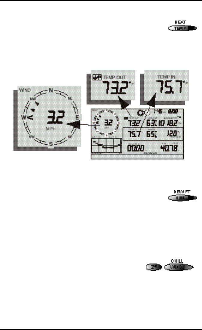
1. Compass Rose
The wind rose displays the speed and direction of the current wind, as well
as the variation in wind direction over the last three <!-- true?--!> minutes
2. Graph and Hi / Low mode settings
Combinations of these indicators appear only when the Hi /Low or Graph
modes are selected.
3. Forecast Icons
From left to right, these icons represent predicted snow, rain, clouds, partly
sunny, and sun. The forecast is updated every three hours.
Vantage Pro console display
Chapter 3
Page 16 Vantage Pro Console Manual
4. Moon Phase Indicator
The moon phase indicator depicts the current phase of the moon.
5. Time / Sunrise Time
Time may be displayed in 12 or 24 hour format. Time of sunrise is also dis-
played in this field. You must enter the correct correct lattitude and longi-
tude for your location for the time of sunrise to be accurate.
6. Date / Sunset Time
Date may be displayed in day / month or month.day format. Time of sunset
is also displayed in this field. You must enter the correct lattitude and longi-
tude for your location for the time of sunset to be accurate.
7. 2nd button indicator
The 2nd indicator icon lights when the 2nd button is pushed.
8. Barometric Trend Arrow
The barometric trend arrow displays the pressure trend in five dif-
ferent positions: strongly rising, rising, steady, falling, and strongly
falling.
The steeply rising (or falling) arrow indicates the pressure has
increased (or decreased) 0.06” Hg or more in three hours.
The shallow rising (or falling) arrow indicates the pressure has increased (or
decreased) more than 0.02” Hg, but less than 0.06” Hg over three hours.
A flat arrow indicates the pressure has changed less than 0.02” Hg in three
hours.
9. Graph Icon
The graph icon is always displayed next to the active weather vari-
able. The graph will always show that variable’s history according to
your settings.

Display Features
Vantage Pro Console Manual Page 17
10.Current Rain Indicator
The umbrella icon announces that it is currently raining.
11. Staton Number Indicator
The station number indicator shows which sensor transmitter
the console is currently displayed.
Note: Multiple sensors are available for the wireless Vantage Pro system only.
12. Weather Ticker
The Davis Weather Ticker is a unique and useful addition to the weather sta-
tion console. The ticker displays a broad spectrum of messages to the con-
sole user, including instructions during console setup.
The ticker also displays detailed forecast messages.
13. Graph Lock mode indicator
This padlock icon activates to show that you have locked the graph
in a particular setting (see “Graph Mode” on page 27).
14. Graph Field
The graph features an astounding array of features that I haven’t quite fin-
ished thinking about and will write later.
Vantage Pro console display

Chapter 3
Page 18 Vantage Pro Console Manual
15. Alarm icon
The bell icon is active when an alarm is set. <!-- What about when alarm
going off?--!>
SE T U PMO D E
<!--Not yet written--!>
CU R R E N TWE A T H E RMO D E
The Current Weather screen is the heart of the display and where you’ll likely
spend most of your time. Up to ten weather variables are displayed simulta-
neously on the Vantage Pro’s LCD screen. Some of these variables are always
displayed: Barometric pressure, Outside Temperature, and Outside Humidity,
as well as Wind Direction. Other variables share display space and must be
accessed through keypresses.
Activating Weather Variables
Displaying any current weather information is straightforward. Press any func-
tion key to display that weather variable’s current value. Selecting a variable
also activates that variable’s graph.
Note: The graph icon is always displayed next to the active weather variable.
You can also select any variable currently displayed on the LCD screen using
the navigation keys. Pushing the left, right, up, or down arrows will move the
graph icon to the next data field in the selected direction.
Wind Speed and Direction
• Wind Speed
Press the WIND / CHILL key to select the wind speed
field. Wind speed may be displayed in miles per hour
(mph), kilometers per hour (kph), meters per second (m/
s), and knots (knots).
• Wind Direction
The large arrow within the wind rose graphically displays the cur-
rent wind direction. Smaller arrows display the range of wind direc-
tion within the last 3 minutes.
To activate a digital readout of the wind direction, press the WIND / CHILL
key again. The digital wind direction is displayed in degrees. See “Wind” on
page 34.
Temperature
Current Weather Mode
Vantage Pro Console Manual Page 19
• Outside Temperature
Press the TEMP / HEAT key to select the outside temperature
field. Note that the graph icon appears next to the data field.
Temperature data may be displayed in both degrees Farenheit
(ºF) and Centigrade (ºC).
• Inside Temperature
Press the TEMP / HEAT key again to activate the inside temperature field.
Again, the graph icon appears next to the data field.
Humidity
Press the HUM / DEW PT key to select the outside humidity
field.
Press the HUM / DEW PT key again to activate the inside
humidity field.
Humidity is displayed in percent relative humidity. See “Relative Humidity”
on page 37.
Wind Chill
• Current Wind Chill
Press and release the 2ND key, then press the WIND
/ CHILL key to select the Wind Chill field.
Wind Chill is displayed either degrees Farenheit (ºF)
or Centigrade (ºC). See “Apparent Temperature
Measures” on page 32.
Dew Point

Chapter 3
Page 20 Vantage Pro Console Manual
• Current Dew Point
Press and release the 2ND key, then press the
HUM / DEW PT key to select the Dew Point
field.
Dew Point is displayed in either degrees Farenheit (ºF) or Centigrade (ºC). See
“Dew-Point & Leaf Wetness” on page 37.
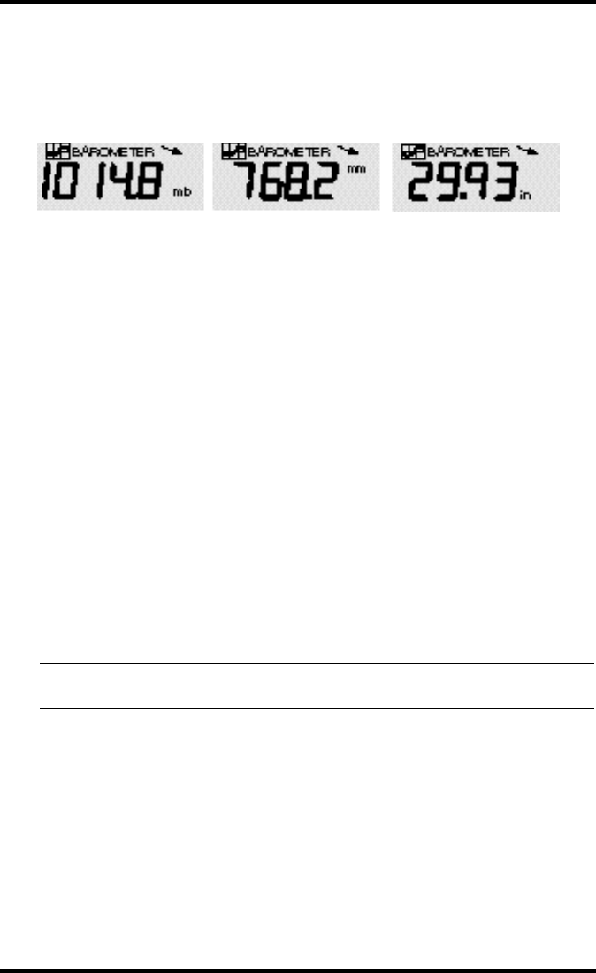
Barometric Pressure
• Current Barometric Pressure
Press the BAR / ET key to select the barometric pressure.
Barometric pressure may be displayed in inches (in), millime-
ters (mm), millibars (mb) or hectoPascals (hPa). See “Baromet-
ric Pressure” on page 36.
• Pressure Trend Arrow
The Barometric Trend Arrow depicts the current barometric trend, measured
over the last 3 hours. The trend arrow is always displayed, whether the baro-
metric pressure is selected or not.
UV (Ultraviolet Radiation)
• Current UV
Press the UV / SUN key to display the current UV read-
ing.
UV may be displayed as an index (1-7) or in MEDS. See
“UV (Ultra Violet) Radiation” on page 35.
Humidity, Pressure, Dew Point, & Wind Chill

Current Weather Mode
Vantage Pro Console Manual Page 21
Heat Indices
• Heat Index
Press and release the 2ND key, then press the
TEMP / HEAT key to display the Heat Index. See
“Apparent Temperature Measures” on page 32.
• THW Index
Repeat the sequence, (i.e. 2ND, TEMP / HEAT ) to
display the THW (Temperature - Humidity - Wind Index) (See “Apparent Tem-
perature Measures” on page 32).
• THSW Index
If you have installed the optional Solar Radiation Sensor, repeat the sequence
one more time to display the THSW (Temperature - Humidity - Sun - Wind
Index). See “Apparent Temperature Measures” on page 32.
All heat indices appear in the same place on the screen and may be displayed,
like temperature and wind chill, as either degrees Farenheit (ºF) or Centigrade
(ºC).
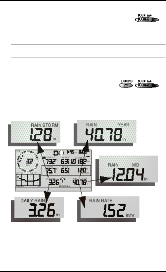
Rain “Year”, Rain “Month”, and Rain Rate
• Rain Rate
Press the RAINYR / RAINDAY key to display the current rain rate.
Rain Rate may be displayed as either inches per hour (in/hr) or millimeters per
hour (mm/hr).
• Month-to-date precipitation
Press the RAINYR / RAINDAY again to select the month-to-date precipitation
record. Monthly rain displays the precipitation accumulated over the last 30
days.
Chapter 3
Page 22 Vantage Pro Console Manual
• Year-to-date precipitation
Press the RAINYR / RAINDAY key a third time to display
the year-to-date precipitation record. Yearly rain displays
the precipitation accumulated since XXXX. Year-to-date
precipitation is displayed in inches (in) or millimeters
(mm).
Note: The“Year-to-date” and “Month-to-date” registers record precipitation accumulation for 1 year and 1
month respectively; however, you may clear start each counting period at whatever date you wish.
“Daily” and “Storm” Rain
• “Daily” Rain
Press and release the 2ND key, then press the
RAINYR / RAINDAY key. Daily Rain displays the
rain accumulated over the last 24 hours.
• “Storm” Rain
Repeat the above sequence: press and release the 2ND key, then press the
RAINYR / RAINDAY key.
All rain accumulation may be displayed as either millimeters (mm) or inches
(in).
Solar Radiation
Daily Rain, Rain Storm, Rain Year, Rain Month, & Rain Rate

Current Weather Mode
Vantage Pro Console Manual Page 23
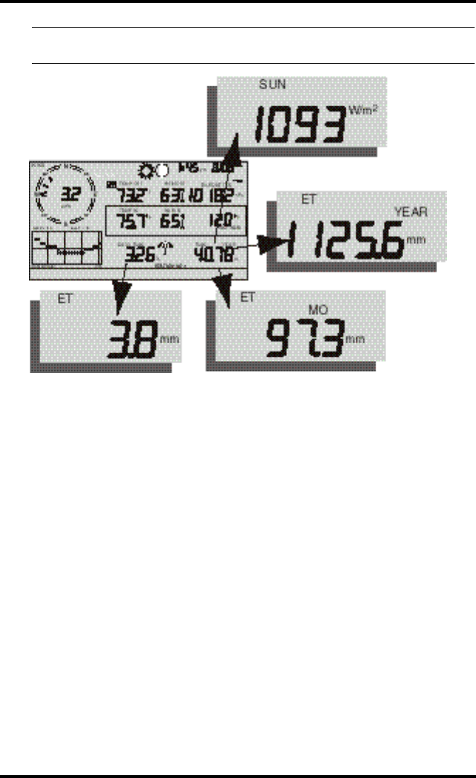
• Current Solar Radiation
Press and release the 2ND key, then press the UV /
SUN key to display the current solar radiation
reading.
Solar radiation is displayed as Watts per square
meter (W/m2). See “Solar Radiation” on page 34.
Note: To display solar radiation readings, you must have installed the optional Solar Radiation sensor.
(XREF)
ET (Evapotranspiration)
• Current ET
Press and release the 2ND key, then press the BAR /
ET key to display the current evapotranspiration
reading. See “EvapoTranspiration (ETo)” on
page 32.
• Monthly ET
Repeat the sequence (i.e. Press and release the 2ND key, then press the BAR /
ET key) to display Monthly ET.
• Yearly ET
Repeat the sequence a third time to display Yearly ET.
Chapter 3
Page 24 Vantage Pro Console Manual
Note: To display ET readings, you must have installed the optional Solar Radiation sensor and the optional
Leaf Wetness sensor.
Selecting Units
Most weather variables may be displayed in at least two different units, typi-
cally the English and Metric systems, although some variables feature more
possibilities. Barometric pressure, for example, may be displayed in millibars,
millimeters, inches, or hectoPascals.
You may change the units display at any time.
To change the units for any variable:
1. Activate the variable using the keypress sequences described above. (See “Activating
Weather Variables” on page 18.)
2. Press and release the 2nd key.
3. Press the Graph / Units key.
The selected variable’s units will change. Repeat steps 2 and 3 until the
desired units appear.
Current ET, ET Month, ET Year, & Solar Radiation
Highs and Lows Mode
Vantage Pro Console Manual Page 25
For example, to select Barometric pressure units, activate the Barometric
presure by pushing BAR. Next, press and release the 2nd key, then press the
Graph / Units key. The units field will display millibars, millimeters, inches, or
hectoPascals. Repeating these steps cycles through all four selections. Stop
when the the desired unit appears.
HIG H SA N D LO W S MO D E
<!--This section doesn’t jibe with Vantage Pro - because we don’t know how the
alarms mode will work yet--!> The Vantage Pro records highs and lows for
many weather conditions. All highs and lows represent the maximum or mini-
mum reading since the last time you cleared each individual high/low register.
If you have enabled the AutoClear for a particular high/low (see “Enabling/
Disabling AutoClear” on page 51), this reading will represent the high/low
since the time of the AutoClear. In other words, it will track highs and lows
over a 24 hour period. If you do not use AutoClear, you may track daily,
weekly, monthly, or yearly values, depending on how often you manually clear
them.
For most highs and lows, the time and date at which they occurred is stored
along with the value. Please note, however, that the date is only stored as long
as it falls within 14 days of the current date. After 14 days, the Vantage Pro dis-
plays only the high/low reading and the time; the date appears as a series of
dashes.
Note: (<!--Using Barometric Pressure not yet written --!> for details on the stored baro-
metric pressure.
Barometric Pressure: millibars (mb), millimeters (mm) and inches (in)

Chapter 3
Page 26 Vantage Pro Console Manual
The table below summarizes the highs and lows stored by the Vantage Pro.
ALA R M S MO D E
The Vantage Pro features a set of alarms which can be programmed to sound
whenever a reading exceeds a set value. With the exception of barometric pres-
sure, dew-point, and time, all alarms sound when a reading reaches the alarm
threshold and will continue to sound until the reading returns to within the
threshold. This means that for all high alarms, the alarm sounds when a read-
ing reaches the alarm threshold continues to sound until the reading drops
below the alarm threshold. On all low alarms, the alarm sounds when a read-
ing reaches the alarm threshold and continues to sound until the reading rises
above the alarm threshold.
The table below summarizes the Vantage Pro’s alarms.
CONDITION HIGH LOW TIME &
DATE AUTOCLEAR ADDITIONAL
INFORMATION
Air Temperature Yes Yes Yes Yes
Soil Temperature Yes Yes Yes
Temp/Hum Index Yes Yes Yes
Wind Chill Yes Yes Yes
Wind Speed Yes Yes Yes Direction of Gust
Rate of Rainfall Yes Yes Yes
Relative Humidity Yes Yes Yes Yes
CONDITION HIGH
ALARM LOW
ALARM SPECIAL ALARM OR FEATURE
“Daily” ETo Yes Hourly Update, Resets “Daily” ETo
Total ETo Yes
Total Degree-Days for Period Yes
Air Temperature Yes Yes
Soil Temperature Yes Yes
Temp/Hum Index Yes
Wind Chill Yes
Wind Speed Yes
“Daily” Rainfall Yes
Barometric Pressure Rate of Change per Hour
Relative Humidity Yes Yes
Dew-Point Temperature within 2˚F (1˚C) of Dew-Point
Time Standard “Alarm Clock”

Graph Mode
Vantage Pro Console Manual Page 27
The three special alarms are described below:
• ETo
ETo is updated only once an hour, on the hour. If during a given hour the
ETo value exceeds the alarm threshold, that information causes the ETo
alarm to sound at the end of that hour. This is true for both the “daily” and
Total ETo alarms.
In addition, for the “daily” alarm, the Vantage Pro automatically subtracts
the ETo alarm threshold value from the “daily” ETo amount after the alarm
is triggered. (This subtraction effectively clears “daily” ETo once the alarm
is triggered.) Thus, if you are using the “daily” ETo alarm (at any thresh-
old), do not use the ETo AutoClear feature because: (1) there is no need, the
value resets automatically, and (2) setting the ETo AutoClear may interfere
with triggering the alarm at the appropriate time.
A new feature in the Vantage Pro allows you to set the station to generate a
signal for every hundredth-inch of ETo. For example, if in an hour, three-
hundredths of an inch ETo is returned to the air, at the end of the hour 3 dis-
crete signals will be generated by the station. For this application, set the
alarm threshold to 0.01”, and attach an Alarm Output Module (AOM) to
receive the signal. Any other threshold (other than 0.01”) will cause the
alarm to function as normal (giving just one signal at the end of the hour
when the alarm threshold is exceeded).
Note: In order for the alternative (0.01”) setting to work, you must have an AOM connected to
your system, otherwise the ETo alarm will sound continuously. Also, make sure you set the
alarm threshold in inches (even if you are displaying total ETo in millimeters).
• Barometric Pressure
The barometric pressure alarm alerts you to changes in barometric pres-
sure. You may select a rate of change per hour (0.2”/0.4”/0.6”, 0.5 mm/
1.0 mm/1.5 mm, 0.7 hPa/1.4 hPa/2.0 hPa) and the Vantage Pro’s alarm
will sound if the rate of change (in either direction) exceeds your threshold.
• Dew-Point
The Dew-Point alarm alerts you when the temperature comes within 2˚F
(1˚C) of the dew-point.
• Time
The time alarm is a standard “alarm clock” type of alarm. It will sound for
one minute.
GR A P H MO D E
<!-- Not yet written --!>

Chapter 3
Page 28 Vantage Pro Console Manual

Vantage Pro Manual Page 29
TR O U B L E S H O O T I N G
While the Vantage Pro is designed to provide years of trouble-free operation,
occasional problems may arise. If you are having problems with your unit,
please check the following guide before sending the unit in for repair. You will
be able to solve many of the problems yourself. If, after checking this guide,
you are unable to solve the problem, please call the factory at 1-510-732-7814
for further instructions. Please do not return your unit for repair without prior
authorization.

Troubleshooting
Page 30 Vantage Pro Manual
Problem Solution PG.
Display is flashing Cabled Vantage Pro is operating under
battery power. Check to be sure that the
power adapter had not come unplugged
from the console or outlet.
Display is blank Unit is not receiving power. Check to be
sure the power adapter has not come
unplugged from the console or outlet.
If power is interrupted, battery may be
installed incorrectly. Check and re-install.
Battery may be run down or old. Replace.
Display shows a series
of dashes in place of
function reading
ISS not plugged in (Cabled Vantage Pro)
Sensors not transmitting. (Wireless Van-
tage Pro) See transmitter manual.
Console not receiving. (Wireless) Check
reception.
A reading has exceeded the limits indi-
cated in the specifications table.
For temperature, wind speed, or rainfall:
calibration nmbers may be causing read-
ings to exceed display limits. Check cali-
bration number and adjust if necessary.
Display is sluggish or
computer does not
work at low tempera-
tures
The console, LCD display, and internal
components may not work below 32º F (0º
C). Use the External Temperature sensor in
low-temperature locations and keep the
Vantage Pro console in a warmer location.
Display “locks up” The Vantage Pro console may “lock up” if
there is a power surge. To restore the unit,
remove all power (including battery
backup) and then restore power. If “lock
ups” occur frequently, add a surge sup-
pressor to the power line.
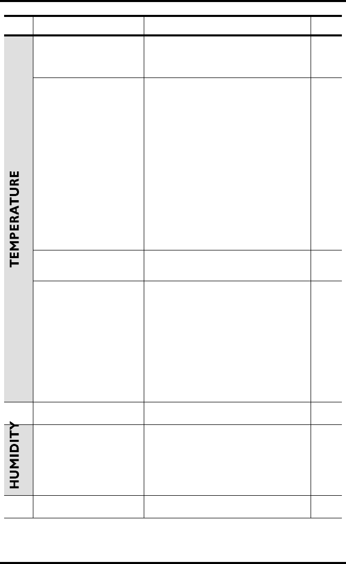
TEMPERATURE
Vantage Pro Manual Page 31
Outside temperature
sensor reading seems
too high
Check calibration number and adjust if
necessary.
Inside temperature
sensor reading seems
too high
Move the Vantage Pro console (or other
temp sensor if you have installed addi-
tional wireless temperature sensors) out of
direct sunlight.
Make sure that the console or sensor is not
in contact with an exterior wall that heats
up in sunlight or when outside tempera-
ture rises.
Make sure the console or sensor is not near
a heater or other internal heat source
(lamps, appliances, etc.).
Check calibration number and adjust if
necessary.
Outside temperature
seems too low Check calibration number and adjust if
necessary.
Inside temperature
sensor reading seems
too low
Make sure the the console or other tem-
perature sensor is not in contact with an
exterior wall that cools down when out-
side temperature drops.
Make sure the console or other tempera-
ture sensor is not near an air conditoning
vent.
Check calibration number and adjust if
necessary.
Inside humidity seems
too high or too low Make sure the Vantage Pro console is not
near a humidifier or de-humidifier.
Check calibration number and adjust if
necessary.
Problem Solution PG.
Troubleshooting
Page 32 Vantage Pro Manual
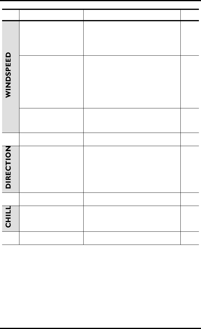
Wind speed reading
seems lower than
expected
Check installation by spinning wind cups.
If you get a reading, teh wind cups are
installed correctly. They should spin more
freely after an initial break-in period of
one or two weeks.
Wind speed reads 0
either all the time or
intermittently
Check installation by spinning wind cups.
If you do not get a reading, try moving the
wind cups down about 1/16” (1.5mm) on
the shaft.
If you still do not get a reading, the prob-
lem may be with the anemometer. Call fac-
tory for return authorization.
Wind speed reading
seems too high or too
low.
Check calibration number and adjust if
necessary.
Wind direction reading
is dashed out Possibility 1
If these steps do not reveal the problem,
the anemometer may be faulty. Call the
factory for return authorization.
Wind chill reading
seems too high or too
low
Check calibration number for temperature
adn wind speed. Adjust if necessary.
Problem Solution PG.

Vantage Pro Manual Page 33
RE P A I R &
WA R R A N T Y
I N F O R M A T I O N
ON E YE A R LIM IT E DWA R R A N T Y
For details on Davis’ warranty policy, please refer to the Maintenance, Service,
and Repair Information brochure included with your station.
QU E S T IO N S? CA L LT H E DA V IS SE R V IC ECE N T E R
If you have any questions about our products, please call our Service Center at
1-510-732-7814. We'll be glad to help. Most questions can be answered while
you're on the phone. Sorry, we’re unable to accept collect calls.

Repair & Warranty information
Page 34 Vantage Pro Manual
FCC PA R T 15 CL A S S B R E G IS T R A T IO NWA R N IN G
This equipment has been tested and found to comply with the limits for a Class
B digital device, pursuant to Part 15 of the FCC Rules. These limits are
designed to provide reasonable protection against harmful interference in a
residential installation. This equipment generates, uses, and can radiate radio
frequency energy and, if not installed and used in accordance with the instruc-
tions, may cause harmful interference to radio communications.
However, there is no guarantee that interference will not occur in a particular
installation. If this equipment does cause harmful interference to radio or tele-
vision reception, which can be determined by turning the equipment on and
off, the user is encouraged to try to correct the interference by one or more of
the following measures:
• Reorient or relocate the receiving antenna.
• Increase the separation between the equipment and receiver.
•Connect the equipment into an outlet on a circuit different from that to which the
receiver is connected.
• Consult the dealer or an experienced radio/TV technician for help.
Shielded cables must be used for this equipment to comply with the relevant
FCC regulations. [Previous sentence necessary?] Changes or modifications not
expressly approved in writing by Davis Instruments may void the user's
authority to operate this equipment.
Product Numbers: xxxx, xxxx, xxxx, xxxx
David Instruments Part Number: xxxx-xxx
Vantage Pro Console Manual
Rev. A Manual (8/20/99)
This product complies with the essential protection requirements of
the EC EMC Directive 89/336/EC.
© Davis Instruments Corp. 1999. All rights reserved.