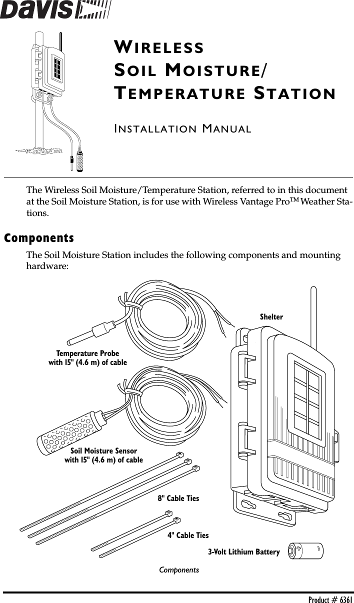
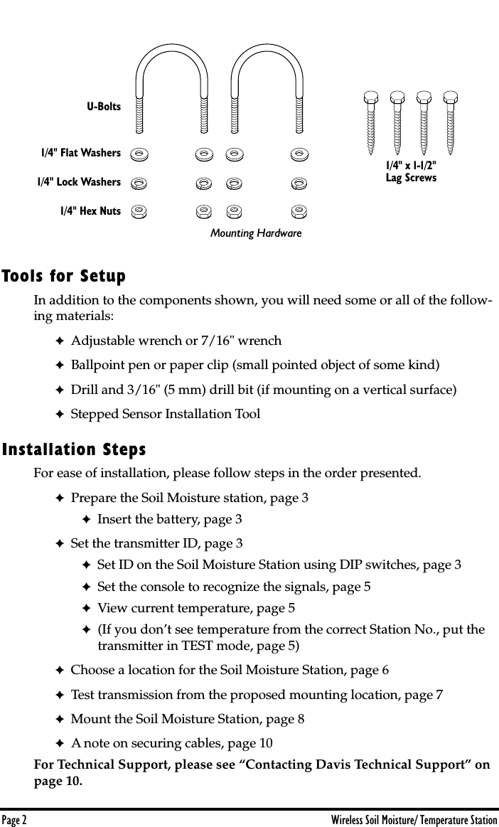
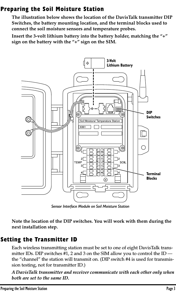
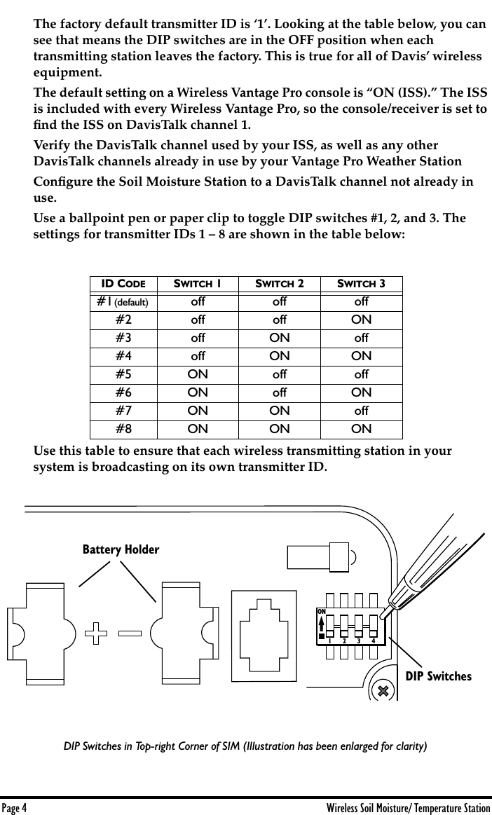
Davis Instruments DWW6361 Soil Moisture Station, 6361 User Manual 6361 SMT Station FCC

Davis Instruments Soil Moisture Station, 6361 6361 SMT Station FCC

Manual

 Product # 6361 W IRELESS  S OIL  M OISTURE / T EMPERATURE  S TATION I NSTALLATION  M ANUAL The Wireless Soil Moisture/Temperature Station, referred to in this document at the Soil Moisture Station, is for use with Wireless Vantage Pro TM  Weather Sta-tions.  Components The Soil Moisture Station includes the following components and mounting hardware:Soil Moisture Sensorwith 15" (4.6 m) of cableTemperature Probewith 15" (4.6 m) of cableShelter3-Volt Lithium Battery8" Cable Ties4" Cable TiesComponents
 Page 2 Wireless Soil Moisture/ Temperature Station Tools for Setup In addition to the components shown, you will need some or all of the follow-ing materials: ✦ Adjustable wrench or 7/16" wrench ✦ Ballpoint pen or paper clip (small pointed object of some kind) ✦ Drill and 3/16" (5 mm) drill bit (if mounting on a vertical surface) ✦ Stepped Sensor Installation Tool Installation Steps For ease of installation, please follow steps in the order presented.  ✦ Prepare the Soil Moisture station, page 3 ✦ Insert the battery, page 3 ✦ Set the transmitter ID, page 3 ✦ Set ID on the Soil Moisture Station using DIP switches, page 3 ✦ Set the console to recognize the signals, page 5 ✦ View current temperature, page 5 ✦ (If you don’t see temperature from the correct Station No., put the transmitter in TEST mode, page 5) ✦ Choose a location for the Soil Moisture Station, page 6 ✦ Test transmission from the proposed mounting location, page 7 ✦ Mount the Soil Moisture Station, page 8 ✦ A note on securing cables, page 10 For Technical Support, please see “Contacting Davis Technical Support” on page 10.1/4" x 1-1/2"Lag ScrewsU-Bolts1/4" Flat Washers1/4" Lock Washers1/4" Hex NutsMounting Hardware
 Preparing the Soil Moisture Station Page 3 Preparing the Soil Moisture Station The illustration below shows the location of the DavisTalk transmitter DIP Switches, the battery mounting location, and the terminal blocks used to connect the soil moisture sensors and temperature probes.Insert the 3-volt lithium battery into the battery holder, matching the “+” sign on the battery with the “+” sign on the SIM.Note the location of the DIP switches. You will work with them during the next installation step.  Setting the Transmitter ID Each wireless transmitting station must be set to one of eight DavisTalk trans-mitter IDs. DIP switches #1, 2 and 3 on the SIM allow you to control the ID — the “channel” the station will transmit on. (DIP switch #4 is used for transmis-sion testing, not for transmitter ID.)  A DavisTalk transmitter and receiver communicate with each other only when both are set to the same ID.  3-Volt Lithium BatteryDIPSwitchesTerminalBlocksSensor Interface Module on Soil Moisture Station
 Page 4 Wireless Soil Moisture/ Temperature Station The factory default transmitter ID is ‘1’. Looking at the table below, you can see that means the DIP switches are in the OFF position when each transmitting station leaves the factory. This is true for all of Davis’ wireless equipment.The default setting on a Wireless Vantage Pro console is “ON (ISS).” The ISS is included with every Wireless Vantage Pro, so the console/receiver is set to find the ISS on DavisTalk channel 1. Verify the DavisTalk channel used by your ISS, as well as any other DavisTalk channels already in use by your Vantage Pro Weather StationConfigure the Soil Moisture Station to a DavisTalk channel not already in use. Use a ballpoint pen or paper clip to toggle DIP switches #1, 2, and 3. The settings for transmitter IDs 1 – 8 are shown in the table below: Use this table to ensure that each wireless transmitting station in your system is broadcasting on its own transmitter ID.  DIP Switches in Top-right Corner of SIM (Illustration has been enlarged for clarity) ID C ODE S WITCH  1S WITCH  2S WITCH  3 #1  (default)    off off off#2 off off ON#3 off ON off#4 off ON ON#5 ON off off#6 ON off ON#7 ON ON off#8 ON ON ON1234ONBattery Holder DIP Switches
 Setting the Transmitter ID Page 5 Setting Console/Receiver(s) to Same ID 1. Put your console into Setup Mode — press and hold the DONE key and press the DOWN arrow key.  The console will show you Screen 1: Transmitters. You should see the words: “RECEIVING FROM...” and “STATION NO.” followed by the transmitter IDs that your console detects. One of these should be the ID number you just set on the Soil Moisture Station transmitter. If you don’t see it, make sure the console is within 10' of the transmitter, and verify that you set the DIP switches correctly. If you still don’t see it, go to “TEST mode” on the next page.  2. Press the DONE key to move on to Screen 2: Selecting Transmitters.  Setup Mode – Screen 2 is where you will set the console to recognize signals on that ID as coming from a Soil Moisture Station. 3. Press the LEFT or RIGHT arrow key, or the STATION key, to scroll through transmitter IDs. When you see the ID you chose for the Soil Moisture Station, use the UP or DOWN arrow keys to activate reception of that ID code. Make sure the screen shows “ON”.  4. Press the GRAPH key to change the type of station assigned to that transmitter ID. Press the GRAPH key until the word “TEMP” appears. 5. To exit Setup Mode, press and hold the DONE key. (See the Vantage Pro User’s Manual & Setup Guide: “Setup Mode – Screen 2: Selecting Transmitters.”)  Viewing Current Soil Moisture and Temperature Press the TEMP key until you see “SOIL MOIST” displayed on the console screen where the inside temperature is usually displayed. If you see SOIL MOIST and no number, you are seeing the moisture and temperature readings for sensor pair #1. If you continue to press the TEMP key, you will see the readings for sensor pairs #2, #3, and #4. If no sensors are installed the reading will be dashed out. This confirms communication between your Soil Moisture Station and the console — go on to “Choosing a Location for the Soil Moisture Station & Sensors” on page 6.  If You Do Not See Current Values from the Correct Station No. First, verify that the console/receiver is powered and is not in Setup Mode (exit Setup Mode by pressing DONE key and holding it for a moment). Then, on the Soil Moisture Station, check that the battery is properly installed. Walk around the room with the console, standing for a few moments in various locations to see if you are picking up signals. If you don’t see readings no matter where you stand with the console, put the transmitter in TEST mode.
 Page 6 Wireless Soil Moisture/ Temperature Station TEST mode  DIP switch #4 on the SIM (see illustration on page 4) is the TEST DIP-switch. Switch it to the ON position using a ball-point pen or paper clip. This puts the transmitter in  Test Mode.  An LED indicator light will flash each time it transmits:  ✦ The LED will immediately flash once to show that the light itself func-tions. ✦ Then it will flash each time the transmitter broadcasts a signal, which should be every 10 seconds.  If the LED flashes only once and then remains dark, there is a problem with the transmitter. See “Contacting Davis Technical Support” on page 10.If the LED flashes repeatedly but your console isn’t picking up a signal anywhere in the room, it could be related to one of the following causes:  1. The DIP switches were not correctly set on the transmitter.  Review the procedure on page 3.  2. The ID was not correctly set on the console/receiver.  Review the procedure on page 5.  3. Reception is being disrupted by RF (radio frequency) interference.4. There is a problem with the console/receiver.  See “Contacting Davis Technical Support” on page 10. Note: Remember to  turn the Test DIP switch OFF  when you’re finished testing wireless transmis- sion. If it is left ON, the blinking LED will reduce battery life significantly.  Choosing a Location for the Soil Moisture Station & Sensors The Watermark   soil moisture sensors should be located at root depth for best results. Shallow rooted crops with a root depth of less than 12” may only require one soil moisture sensor. Deeper rooted row crops, small grains, vines and trees generally require sensors located in at least two depths. The basic principal is that the sensors must be located within the effective root system of the crop. Guidelines on proper depths for specific crops and conditions can be obtained from your local farm advisor.While not absolutely necessary for operation, we also recommend that a tem-perature probe be installed with each soil moisture sensor. This allows the soil moisture sensor’s readings to be temperature compensated for better accuracy. Range of Wireless Transmission The range of wireless transmission depends on many factors. For the best reception, position the transmitter shelter and your console/receiver as close together as possible.
 Testing Transmission from Proposed Location Page 7 Range is up to 400' (125 m) in the line of sight, under optimal conditions. Typical range under most conditions is 100' to 200' (45 to 150 m), but this may be reduced by walls, ceilings, trees, or foliage. Radio-frequency interference (RF) can also reduce transmission distance. Cordless phones and ham radios are common examples of RF interference.A metal roof or other large metal structure can interfere with the signal (aluminum siding, a furnace with metal ducts, and your refrigerator are examples). Sometimes transmission between wireless units is obscured by something you cannot identify, or by some obstacle that you can’t work around. If necessary, consider using Wireless Repeater #7624 or #7625 to strengthen the signal or increase the distance between the transmitter and the console/receiver.  Testing Transmission from Proposed Location It is  very important  to test reception from the proposed location  before  perma-nently mounting the Soil Moisture Station.  Place the shelter at the intended mounting site, or have someone hold it there, so you can walk around with the console/receiver for a few minutes. Rotating the antenna may help to improve reception. Test wireless reception anywhere you might want to use or mount your console/receiver now or in the future. Take your time. If you aren’t picking up strong signals where you intend to place your console, better to move the shelter now than after it has been mounted. Experiment. If you have irregular terrain in the area, it may interfere with the signal. For example, if the transmitter is mounted downhill from the console/receiver, the ground may block a wide angle of the transmitted signal.
 Page 8 Wireless Soil Moisture/ Temperature Station Mounting the Soil Moisture Station Mounting on a Pole 1. While holding the shelter against the pole, place a U-bolt around the pole and through the two holes on at the top of the shelter. 2. Place a flat washer, a lock washer and a hex nut on each of the bolt ends. 3. Using an adjustable wrench or 7/16" wrench, tighten the nuts.4. Place the second U-bolt around the pole and through the two holes at the bottom of the shelter.  Put a flat washer, a lock washer, and a hex nut on each bolt end, and tighten the hex nuts. FlatWasherLockWasherHexNutU-BoltMounting Soil Moisture Station on a Pole
 Mounting the Soil Moisture Station Page 9 Mounting on a Vertical Surface 1. With a 3/16" (5 mm) drill bit, drill two holes approximately 2" (50 mm) apart. Use a carpenter’s level to ensure the holes will be level.2. Drill two more holes 7-1/32" below the upper holes.3. Insert the 1/4" x 1-1/2" lag screws through the flat washers, and through the holes at the top of the shelter into the post.  Using an adjustable wrench or 7/16" wrench, tighten the lag screws. 4. Insert the 1/4" x 1-1/2" lag screws through the flat washers, and through the holes at the bottom of the shelter into the post.  Using an adjustable wrench or 7/16" wrench, tighten the lag screws.FlatWasherLagScrewMounting Soil Moisture Station on a Vertical Surface
 Page 10 Wireless Soil Moisture/ Temperature Station A Note on Securing Cables To prevent fraying or cutting of cables, secure them so they will not whip about in the wind. Secure a cable to a metal pole by wrapping electrical tape around them both. Make sure cables are secure by placing clips or ties approximately every 3 – 5' (1 – 1.6 m). Note: Do not use metal staples or a staple gun to secure cables. Metal staples—especially when  installed with a staple gun—have a tendency to cut the cables. Contacting Davis Technical Support If you have questions about your Soil Moisture Station, or encounter problems installing or operating the station, please contact Davis Technical Support.  Note: Please do not return items to the factory for repair without prior authorization. (510) 732-7814  – Monday – Friday, 7:00 a.m. – 5:30 p.m. Pacific Time.  (510) 732-9229 – For callers outside the USA or Canada.(510) 670-0589 – Fax .www.davisnet.com –  Copies of User Manuals are available on the “Support” page. Watch for FAQs and other updates. Subscribe to the e-newsletter. support@davisnet.com – E-mail to Technical Support.info@davisnet.com – General e-mail. Cable ClipCable Tie
 Specifications Page 11 Specifications ✦ Temperature range: –40 to 140° Fahrenheit (–40 to 60° Celsius) ✦ Primary power input: Solar power – Davis solar charger ✦ Secondary (backup) power: CR-123A 3-volt lithium battery  ✦ Wireless transmission frequency: 916.5 MHz  ✦ 868.35 MHz for overseas version – Product # includes “XA” ✦ Transmitter ID codes: 8 user-selectable ✦ License: low power (less than 1 mW), no license required
 Product Numbers: 6361 Davis Instruments Part Number:  7395.145 Wireless Soil Moisture/ Temperature Station Draft Rev A. Manual (8/7/01)This product complies with the essential protection requirements of the EC EMC Directive 89/336/EC.Copyright © 2001 Davis Instruments Corp. All rights reserved.  3465 Diablo Avenue, Hayward, CA 94545-2778510-732-9229 • Fax: 510-732-9188E-mail: info@davisnet.com  •  www.davisnet.com FCC Part 15 Class B Registration Warning This equipment has been tested and found to comply with the limits for a class B digital device, pursuant to Part 15 ofthe FCC Rules. These limits are designed to provide reasonable protection against harmful interference in a residentialinstallation. This equipment generates, uses and can radiate radio frequency energy and, if not installed and used inaccordance with the instructions, may cause harmful interference to radio communications. However, there is no guar-antee that interference will not occur in a particular installation. If this equipment does cause harmful interference to radio or television reception, which can be determined by turningthe equipment off and on, the user is encouraged to try to correct the interference by one or more of the followingmeasures: ✦ Reorient or relocate the receiving antenna. ✦ Increase the separation between the equipment and receiver. ✦ Connect the equipment into an outlet on a circuit different from that to which the receiver is connected. ✦ Consult the dealer or an experienced radio/TV technician for help.Changes or modifications not expressly approved in writing by Davis Instruments may void the user's authority to oper-ate this equipment.

Navigation menu