Dayton Audio Division of Parts Express WF150A Wi-Fi INTEGRATED AMPLIFIER User Manual TI 435 AMP QSG
Dayton Audio Division of Parts Express Wi-Fi INTEGRATED AMPLIFIER TI 435 AMP QSG
User Manual
1 2 3
VOL+
VOL-
PLAY
ALL
EQ/BAL
WIFI
BT
OPT
LINE 1 LINE 2
PHO
1 2
3
4 5
6
Smart Integrated Amplifier
PLA
Y
AL L
4 5 6
LINE
2
LINE
1
OPT
PHON O
WF150A
Wi-Fi INTEGRATED AMPLIFIER

for purchasing the
WF150A
W i - F i I N T E G R A T E D A M P L I F I E R
We are confident that it will provide reliable,
high
performance sound for many years to
come.

To set up, please...
Download the DaytonAudio
app:
Follow the instructions on screen
Sign
up for news and software
updates:
http://Daytonaudio.com
Play &
Enjoy!
3
1
2
78
3
Smart Integrated Amplifier
PLA
Y
AL L
LINE
2
OPT
4 5 6
LINE
1
PHONO
512 4 9 6
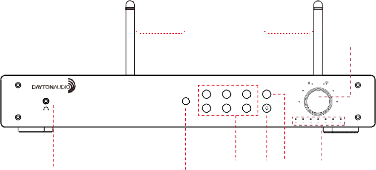
4. Light Button:
Change
the color of the outer ring
surrounding
the
central
dial
9.
Daytonaudio
Smart Integrated
Amplifier
SPE AK ER S OU T
1 2 3 4 5 6 7 8 9 10 11

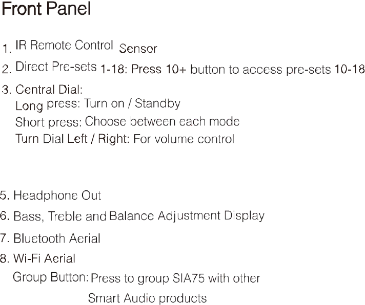
Rear Panel
1.
WPS
Button: Press to connect to Wi-Fi
2. Ethernet / LAN Port: For connecting directly to a router
3. RCA Line In 1: Left / Right. For your
devices
4. RCA Line In 2: Left / Right. For your
devices
5. Phono In: Left / Right. For connecting a turntable
6. Sub Out: For connecting a subwoofer
7. Optical In: For connecting CD player / TV
8. Left / Right speaker out binding posts: For connecting
spe
akers
9. AC Select
10. Mains Power Input
11. Power Button: On / Off
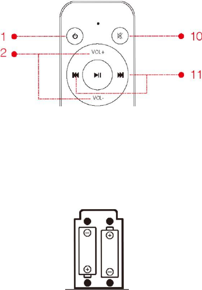
2x
R031
AAA

1. Power On/ Standby
2. volume Up (+) / Down (-)
3. Group Button: Press to group to other Daytonaudio
Smart Audio
products
4. Bass and treble Down(-)
5.
WIFI
Button
6. Bluetooth Button
7. Line 1 Button
8. Line 2 Button
9. Preset Buttons 1-9: Recall direct pre-sets
10. Mute Button
11. Play / Pause Button
12. Light Button: Change the colour of the outer ring surrounding
the central
dial
13. Brass/Treble/Blance control Button
14. Bass and treble
Up(+)
15. Optical Mode Button
16. Phono Mode Button
Connecting the WF150A to
speakers
The WF150A uses screw terminals. Unscrew the terminal and insert the bare end of the cable
into the hole at the base of the terminal. Then tighten securely. Ensure positive + and negative
- are matched with the amplifier /speakers.
FCC Statement
This equipment has been tested and found to comply with the limits for a Class B digital device,
pursuant to Part 15 of the FCC Rules. These limits are designed to provide reasonable
protection against harmful interference in a residential installation. This equipment generates
uses and can radiate radio frequency energy and, if not installed and used in accordance with
the instructions, may cause harmful interference to radio communications. However, there is no
guarantee that interference will not occur in a particular installation. If this equipment does
cause harmful interference to radio or television reception, which can be determined by turning
the equipment off and on, the user is encouraged to try to correct the interference by one or
more of the following measures:
-- Reorient or relocate the receiving antenna.
-- Increase the separation between the equipment and receiver.
-- Connect the equipment into an outlet on a circuit different from that to which the receiver is
connected.
-- Consult the dealer or an experienced radio/TV technician for help.
This device complies with part 15 of the FCC Rules. Operation is subject to the following two
conditions:(1) This device may not cause harmful interference, and (2) this device must accept
any interference received, including interference that may cause undesired operation.
Changes or modifications not expressly approved by the party responsible for compliance
could void the user's authority to operate the equipment.
This equipment complies with FCC radiation exposure limits set forth for an uncontrolled
environment. This equipment should be installed and operated with minimum distance
20cm between the radiator & your body.

daytonaudio.
com tel +
93
7
.
7
43
.
824
8
i
n
f
o
@
day
t
o
n
a
u
d
i
o
.
com
7
0
5 Pleasant
Valley
D
r
.
Springboro,
OH 45
0
66
U
S
A