Deister Electronic MODEL240 Proximity Reader User Manual
Deister Electronic GmbH Proximity Reader Users Manual
Users Manual
GE-Interlogix-CASI
Model-240 Proximity Reader 9/17/2002
Page 1 of 4
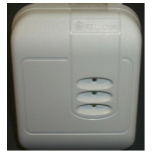
Description
The GE-Interlogix-CASI Model 240 access control badge reader
is an ISO standard compliant, proximity technology badge
reader. The Model 240 reader will read ISO-14443 and ISO-
15693 badges and key tags. The reader’s aesthetically pleasing
contemporary design and light gray housing will complement
any decor.
Features:
• Compatible with Micro/5 2RP and 8RP controllers (not M/5-2SRP)
• Compatible with all Micro/PX(N)-2000 controllers
• Sealed electronics, suitable for outdoor installation
• Tamper switch protected
• Reads ISO-14443 and ISO-15693 access control badges and tags
• Reads badge or tag serial number, no memory sector records required
• User interface: 3-LEDs and beeper
• Fast field maintenance, field wiring plug
• Up to 4” read range (badge type and installation conditions dependent)
• 4-state input supervision of door contact & REX switch: opened, closed, cut, short
• Reader supervision: continuously monitored by the microcontroller
Specifications
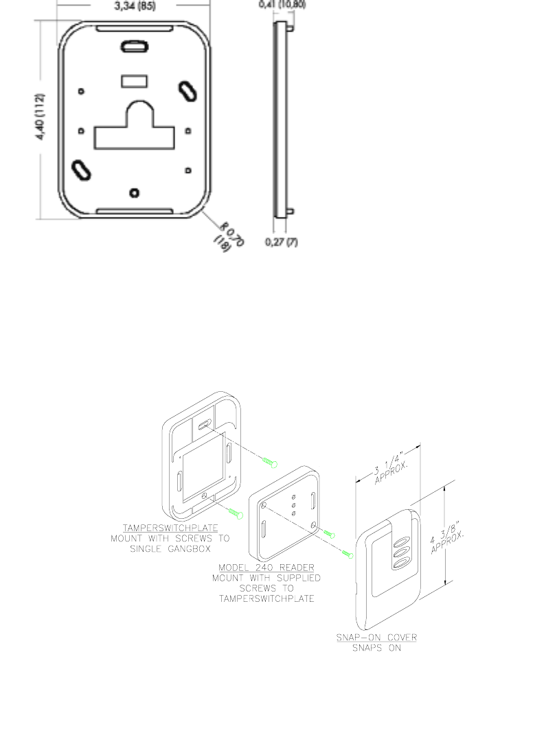
• Mount: on single width USA or European style electrical box or directly on wall
• Material: ASA plastic housing; polyurethane encapsulated electronics
• Housing dimensions: 3.34 x 4.40 x 0.96 inch: (85 x 112 x 24.2 mm)
• Temperature range: -13 to 140 °F /-25 to +70 °C
• Power supply: 8VDC to.30 VDC @ <100 mA
• Electrical protection: Reverse polarity diode protection on power lines
• Data Lines: high-speed transient voltage suppressor diodes
• Protection type: IP 65 (IEC 529). Suitable for outdoor installation
• Frequency: 13.56 MHz
• Approvals: FCC,CE-EN 300 330
• Read distance: up to 2 inches ISO-14443 or up to 4 inches ISO-15693
• Microcontroller firmware versions: Picture Perfect 1.7 or greater recommended
• Interface: Supervised F/2F
• Electrical connection: 12 position plug-in strip connector with screw terminals
• Beeper: controlled by SF2F protocol
• Red LED: controlled by SF2F protocol
• Green LED: controlled by SF2F protocol
• Yellow LED: internal controlled
• RS-485 for reader firmware maintenance and configuration
• Casi pn: 430177001
GE-Interlogix-CASI
Model-240 Proximity Reader 9/17/2002
Page 2 of 4
FCC Cautionary Comment
Modifications to the Model-240 reader not expressly
approved by GE-Interlogix may void the FCC approval.
Model 240 Back plate
Note: Mounting holes fit a standard US single width electrical box and standard
European electrical box hole patterns.
Installation

GE-Interlogix-CASI
Model-240 Proximity Reader 9/17/2002
Page 3 of 4
Installation Considerations
1) Installation of the Model 240 reader on metal
The table below shows the expected read range reduction when a Model 240 reader is
mounted onto a metal plate or wall.
Distance Reading distance
No metal plate 100 %
1.78 inch (4.5 cm) use 4 Surface
Mount Extension plates 100%
1.06 inch, (2.7 cm) use 3 Surface
Mount Extension plates 85 %
0.70 inch (1.8 cm) use 2 Surface
Mount Extension plates 70 %
0.35 inch (0.9 cm) use 1 Surface
Mount Extension plate 50 %
Reader placed on metal wall 10 %
2) Installation of two Model 240 readers side by side
Read range is not affected if the center-to-center distance between two readers is equal to or
greater than 6-inches (15 cm). If the distance between the two readers is less than 6-inches
(15 cm), field interference between the two readers may result in the creation of a dead spot
in the badge read field.
Attention
Two readers may simultaneously read the same badge or tag if the distance between the two
readers is less than 12-inches (30 cm), center-to-center.
GE-Interlogix-CASI
Model-240 Proximity Reader 9/17/2002
Page 4 of 4
3) Installation of two Model 240 readers back to back
For proper operation, readers installed back-to-back must be separated by at least 3.2 inches
(8cm).
Attention
Two readers may simultaneously read the same badge or tag if the distance between the two
readers is less than 6-inches (15 cm), back-to-back.
When using two readers back-to-back on a wall that will separate the two readers by 6 inches
(15 cm) or less, a metal plate (for example aluminium, 4-inches square (10cm x 10cm) must
be placed between the readers. To obtain the maximum read range, mount each Model 240
reader onto one or more Surface Mount Extension plates. Note the impact on badge read
range performance, as discussed in manual section, “Installation Considerations” (above).
Wiring
Reader 12-position field wiring plug Microcontroller
1
2
3
4
5
6
7
8
9
10
11
12
Micro control, reader beeper (option)
Ground
Power, 8VDC to 30VDC
Door Contact
Reader data
Exit Request (REX)
Green LED
Micro control, red LED (option)
RS-485-A, reader firmware maintenance
RS-485-B, reader firmware maintenance
Future
Future
Micro/5PX(N)
2RP and 8RP, see
Micro/5 manual.
DO NOT use the
Model 240 reader with
M/5-S2RP
Micro/PX-2000
Micro/PXN-2000
See micro manual
Micro/Reader-
Junction Box
See manual
Access Control system compatibility
The Model-240 badge reader will output a 16-digit badge identification (BID) number. As a result,
the Model-240 reader is only compatible with Picture Perfect access control systems. The Model-
240 reader is not compatible with Secure Perfect, Secure Perfect Enterprise Edition, SP, or SP-
Enterprise Edition access control systems, (12-digit BID number limitation).
Picture Perfect
A 16-digit BID format must be defined within Picture Perfect. Refer to the Picture Perfect On-line
help for assistance. In brief, go to Access / Badge Formats. Enter a suitable badge format
description, example: “16-digit BID” and define the format: “%16S” (omit the quote characters).
Reader to Micro wiring distance
The maximum reader to micro cable distance is 1,000 feet (305 meters) from the microcontroller
using 4-conductor 22AWG (0.6438mm) shielded cable.