Deister Electronic PRL5AKPL5A RFID Reader User Manual pa prl5a kpl5a multilanguage
Deister Electronic GmbH RFID Reader pa prl5a kpl5a multilanguage
user manual
PRL 5 A•KPL 5 A
Wiring & Installation Instructions
Anschluß & Installationshinweise
V 15/09/11
#896167
Instructions d'Installation et
de Raccordement
PRL 5 A
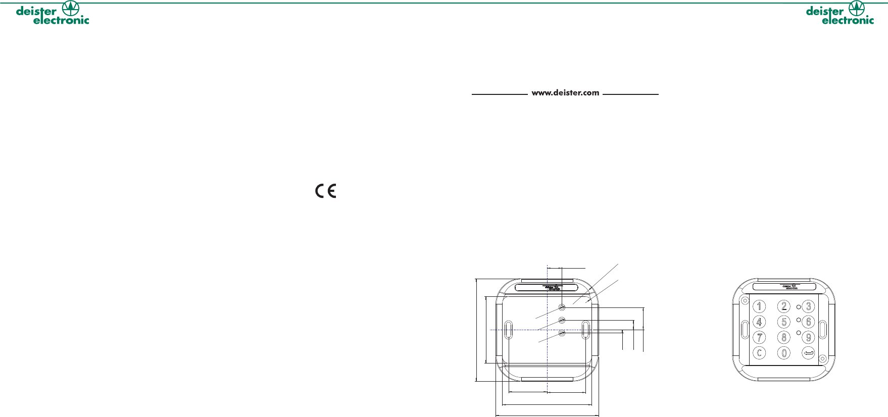
1. Dimensions / Abmessungen (mm):
11,50
30 30
2,43
7,57
17,57
5Ø
5Ø
Ø5
80
80
69,50
52
R5
R20
KPL 5 A
(Dimensions are equal to PRL 5 A)
(Abmaße wie PRL 5 A)
(Les dimensions sont équivalentes à celles du PRL 5 A)
English
Deutsch
Francais
Headquarters
Germany:
deister electronic GmbH
Hermann-Bahlsen-Str. 11
30890 Barsinghausen
Tel.: +49 (0) 51 05 - 51 61 11
Fax: +49 (0) 51 05 - 51 62 17
info.de@deister.com
Americas and Caribbean:
deister electronic USA Inc.
9303 Grant Avenue
Manassas, VA 20110
Tel.: +1 703 - 368 2739
Fax: +1 703 - 368 9791
info.us@deister.com
Great Britain:
deister electronic (UK) Ltd.
Stapleton Way, Enterprise Park
Spalding, Lincolnshire PE12 6ET
Tel.: +44 (0) 1775 - 717100
Fax: +44 (0) 1775 - 717101
info.uk@deister.com
France:
deister electronic france
101 rue Pierre Semard
92320 Chatillon
Tel.: +33 (0) 1 47 - 35 78 78
Fax: +33 (0) 1 47 - 35 92 59
info.fr@deister.com
Japan:
deister electronic Japan, LTD.
Toshiba Hoshikawa Bldg. 4F
2-4 Kawabe-chô
Hodogaya-ku, Yokohama-shi
Kanagawa, 240-0001
Tel.: +81 (0) 45 340 1831
Fax: +81 (0) 45 340 1801
info.jp@deister.com
5. Warning:
It is possible that external interference sources will influence the read range, e.g.
monitors, switching power supplies, power cables parallel to data cables,
mounting on metal etc. LCD monitors have a minimal influence on the read range.
In particular the reader should be mounted on non-metallic material, such as
plastic or wood. Metal screws (M6 - ISO 1207, 4762 or 7045) for mounting the
reader have an insignificant influence on the read range. The unit needs to be
operated with a power source with limited power consumption
according to EN 60950-1 (2001) paragraph 2.5.
5.1 Note:
With growing distance between reader and interference source, the influence
decreases. Use only linear regulated power supplies. deister electronic GmbH
offers suitable power supplies. To reduce the influence of external electrical
interference, connect the cable shield to ground (GND) of the power supply.
5. Warnung:
Es ist möglich, das externe Störquellen die Lesereichweite beeinträchtigen. Dazu
zählen z.B. Monitore, Schaltnetzteile, Stromkabel, Datenkabel oder die Montage
des Lesers direkt auf Metall. LCD-Monitore haben nur einen minimalen Einfluss auf
die Lesereichweite. Im Normalfall sollte der Leser auf nicht- metallisches Material wie
Plastik oder Holz montiert werden. Metallschrauben (M6 - ISO 1207, 4762 oder
7045) für die Montage des Lesers haben einen unbedeutenden Einfluss auf die
Lesereichweite. Das Gerät ist mit einer Stromquelle mit begrenzter
Leistung nach EN 60950-1 (2001) Absatz 2.5 zu betreiben.
5.1 Hinweis:
Bei größer werdender Entfernung der Störquelle reduziert sich deren Einfluss auf
den Leser. Benutzen Sie nur linear geregelte Netzteile. Die deister electronic
GmbH bietet entsprechende Netzteile an. Um den Einfluss externer, elektrischer
Störungen zu vermeiden, verbinden Sie den Masseanschluß (GND) mit der
Erdungsklemme des Netzteils.
5.
5.1 N
Attention:
Il est possible que certaines sources d'interférences extérieures puissant influer sur
la distance de lecture, ex.: moniteurs, mise en/hors service d'alimentations
électriques, câbles d'alimentations à proximités des câbles de données, montage
sur du métal, etc. Les moniteurs LCD ont une influence minimale sur la distance de
lecture.En particulier, le lecteur devra être monté sur une surface non-métalique,
comme sur du plastique ou du bois. Les vis en métal (M6 - ISO 1207, 4762 ou
7045) pour le montage du lecteur ont une influence insignifiante sur la distance de
lecture. Le système doit être alimenté avec une alimentation dont la
puissance de consommation est limitée conformément à la norme
EN 60950-1 (2001) paragraphe 2.5.
ote:
En augmentant la distance entre le lecteur et la source d'interférence, l'influence
décroît. Utiliser seulement des alimentations électriques stabilisées. deister
electronic GmbH propose des alimentations appropriées. Pour réduire l'influence
d'interférences électriques externes, connecter l'écran de protection du câble à la
masse (GND) de l'alimentation électrique.
6. Regulatory notices for Europe:
Hereby, deister electronic GmbH declares that this equipment - if used according
to the instructions - is in compliance with the essential requirements and other
relevant provisions of the RTTE Directive 1999/5/ EC.
6. Zulassungen für Europa:
Hiermit erklärt die deister electronic GmbH, dass sich diese Funkanlage bei
bestimmungsgemäßer Verwendung in Übereinstimmung mit den grundlegenden
Anforderungen und den anderen relevanten Vorschriften der RTTE Richtlinie
1999/5/EG befindet.
6.
A complete declaration of conformity can be requested at:
Eine vollständige Konformitätserklärung kann angefordert
werden unter:
Approved for use all european countries
Zugelassen in allen europäischen Ländern
Avis Réglementation Europe:
Par la présente, deister electronic GmbH, déclare que cet équipement, si utilisé
selon les instructions, est dans la conformité avec les exigences essentielles et
autres dispositions appropriées de la Directive RTTE 1999/5/EC.
Une attestation de conformité peut êtredemandé à:
info@deister-gmbh.de
Approuvé pour utilisation dans tout les pays européens
7. FCC DIGITAL DEVICE LIMITATIONS
Radio and Television Interference
This equipment has been tested and found to comply with the limits for a Class A
digital device, pursuant to part 15 of the FCC Rules. These limits are designed to
provide reasonable protection against harmful interference when the equipment is
operated in a commercial environment. This equipment generates, uses, and can
radiate radio frequency energy and, if not installed and used in accordance with
the instruction manual, may cause harmful interference to radio communications.
Operation of this equipment in a residential area is likely to cause harmful
interference in which case the user will be required to correct the interference at his
own expense.
CAUTION: Changes or modifications not expressly approved by the
manufacturer could void the user’s authority to operate this equipment.
8. CANADIAN RADIO EMISSIONS REQUIREMENTS
This Class A digital apparatus complies with Canadian ICES-003. Cet appareil
numérique de la classe A est conforme à la norme NMB-003 du Canada.
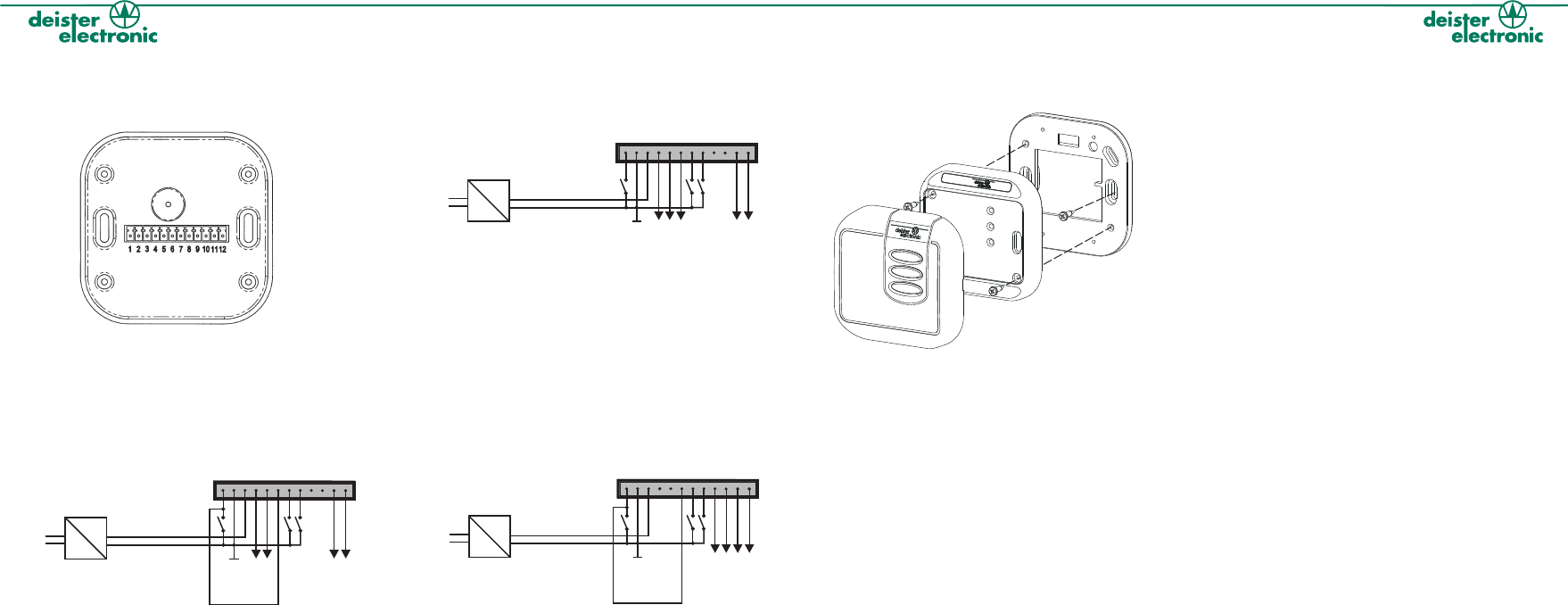
3. Mounting•Montage , :PRL 5 A KPL 5 A
Step1 / Schritt 1
Step3 / Schritt 3
Step2 / Schritt 2
4. Technische Daten
Abmaße:
mm 80 x 80 x 16
:ASA
Elektrischer Schutz: Transienten- und Verpolungsschutz
Schutzklasse: IP 65
Betriebstemperatur:
°C -25 ... 60
Lesereichweite:
mm bis zu 80, abhängig von Transpondertyp und
Umgebungsbedingungen
Schnittstellen: Open Collector, RS 485
Protokoll:
PRL 5 A•KPL 5 A: Wiegand, Data/Clock, Magstripe, RS 485
Spannungsversorgung: 8 ... 30V/DC <150 mA
13,56 MHz
Elektr. Anschluß: 12-poliger Anschlußstecker mit
Schraubklemmen
Formate: Seriennummer, frei definierbare Segmente,
LEGIC Prime, LEGIC Advant
Material
Arbeitsfrequenz:
4. Technical Data
Dimensions Reader:
mm (inch) 80 x 80 x 16 (3.1 x 3.1 x 0.6)
Material: ASA
Electrical protection: Transient and reverse polarity protection
Protection: IP 65
Operating Temperature:
°C (°F) -25 ... 60 (-13 ... 140)
Reading Distance:
mm (inch) up to 80 (3.1) depending on transponder
type and environmental conditions
Interface: Open Collector, RS 485
Protocol:
PRL 5 A•KPL 5 A: Wiegand, Data/Clock, Magstripe, RS 485
Power supply: 8 ... 30 V/DC <150 mA
Operating Frequency 13.56 MHz
Electrical connection: 12-PIN Connector with terminal screw
Formats: Unique number, free designed segment,
LEGIC Prime, LEGIC Advant
Tamper protection: Option, reed contact
:
4.
Dimensions:
mm 80 x 80 x 16
Matériau: ASA
:
Protection: IP 65
:
°C -25 ... 60
mm
Interface: Open Collector, RS 485
Protocol:
PRL 5 A•KPL 5 A: Wiegand, Data/Clock, Magstripe, RS 485
: 8 ... 30V/DC <150 mA
Connexions Electriques:
Formats: Numéro de série Unique, segment défini-
librement, LEGIC Prime, LEGIC Advant
Protection Arrachment: Option, contact ILS
Données Techniques
Protection Electrique Protection surtensions
Protection inversion de polarité
Temp. de Fonctionnement
Distance de lecture:
Jusqu'à 80 dépendant du type de
transpondeur et de l'environnement local
Alimentation
Fréquence de
fonctionnement: 13,56 MHz
Connecteur débrochable 12 bornes à vis
2. Pinning•Pinbelegung• :Raccordement 2.2 Magstripe-Emulation Data/Clock
Des résistances de pull-up doivent être connectées respectivement sur les
bornes Clock et Data. La valeur de ces résistances dépend du courant et de la
tension requise à l'entrée du contrôleur.
Pull-up’s have to be connected to the clock and to the data lines respectively.
The value of the pull-up’s depends on the current and voltage which is required
for the controller-input.
Die Datenausgänge Data/Clock/Card Present müssen mit Pull-Up
Widerständen beschaltet werden. Der Wert der Pull-Up-Widerstände hängt von
der Eingangsspannung des Controllers ab.
DC
AC
green LED
Terminal Block
1
Clock
Data
red LED
GND
Beeper
Tamper Switch
Service
Service
Tamper Switch
2 3 4 5 6 7 8 9101112
Card Present
+8...30V <150mA
2.3 RS 485
DC
AC
green LED
Terminal Block
1
A
B
red LED
GND
Beeper
Pin 6: for internal beep
connect to pin 1
Tamper Switch
unused
Tamper Switch
2 3 4 5 6 7 8 9101112
unused
+8...30V <150mA
2.1 Wiegand 2-Wire
DC
AC
green LED
Terminal Block
1
+8...30V <150mA
D1
D0
red LED
GND
Beeper
Pin 6: for internal beep
connect to pin 1
Tamper Switch
Service
Service
Tamper Switch
2 3 4 5 6 7 8 9101112
Des résistances de pull-up doivent être connectées respectivement sur les
bornes D0/D1. La valeur de ces résistances dépend du courant et de la
tension requise à l'entrée du contrôleur.
Pull-up’s have to be connected to the D0/D1 data lines respectively.
The value of the pull-up’s depends on the current and voltage which is
required for the controller-input.
Die Datenausgänge D0/D1 müssen mit Pull-Up Widerständen
beschaltet werden. Der Wert der Pull-Up-Widerstände hängt von der
Eingangs-spannung des Controllers ab.
L'unité est équipée de drivers de ligne correspondent au standard RS485.
Assurez-vous que les terminaisons du bus RS485 sont appropriées.
The device is equipped with line transceivers according to the RS 485 standard.
Be sure to terminate the RS-485 bus appropriately.
Die Datenleitungen A und B müssen entsprechend des RS 485 Standards
beschaltet werden.
Pas de signal “Badge présent” avec
data/clock.
No Card present signal with data/clock.
Kein Card-Present-Signal bei Data/Clock.