Deister Electronic PRM15SWH2400 Proximity Reader User Manual
Deister Electronic GmbH Proximity Reader
UserManual.wiki
>
Deister Electronic
>
PRM15SWH2400 User Manual
User Manual
Navigation menu
Upload a User Manual
Namespaces
Wiki Guide
HTML
PDF
Info
Views
User Manual
Discussion / Help
Navigation

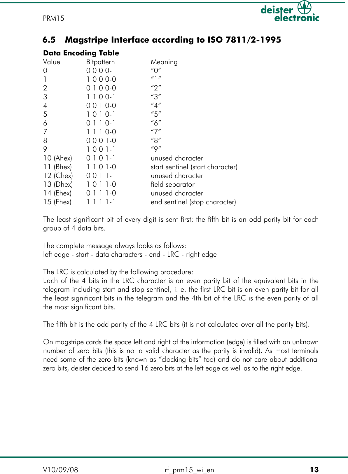
![Calculation of the parity:LRC = 80h OR [52h Å 45h Å 30h Å 43h Å 35h Å 35h Å 37h Å 30h] = E3h (“Å” means Exlusive-OR)V10/09/08 rf_prm15_wi_en 15PRM15](https://usermanual.wiki/Deister-Electronic/PRM15SWH2400/User-Guide-999268-Page-15.png)