Deister Electronic PRM15SWH2400 Proximity Reader User Manual
Deister Electronic GmbH Proximity Reader
User Manual

PRM15
Wiring & Installation
Instructions
V10/09/08

© Copyright 2008 by deister electronic GmbH
All rights reserved. No part of this publication may be reproduced, stored in a retrieval
system, or transmitted, in any form or by any means, electronic, mechanical, photocopying,
recording, or otherwise, without prior written permission of deister electronic GmbH.
deister electronic GmbH reserves the right to make changes to any and all parts of this
documentation without obligation to notify any person or entity of such changes.
September 2008 IO/BF
deister electronic GmbH
Hermann-Bahlsen Str. 11
30890 Barsinghausen
Germany
Phone: +49 (0) 51 05 - 51 61 11
Fax: +49 (0) 51 05 - 51 62 17
E-Mail: info@deister-gmbh.de
Web: www.deister.com
2rf_prm15_wi_en V10/09/08
PRM15

Contents
1. General.......................................................................4
2. Technical Data............................................................5
3. Mechanical Dimensions..............................................6
3.1 Rear view (opened housing).................................................................................7
4. Wiring Diagram..........................................................8
4.1 2-Wire Wiegand.................................................................................................8
4.2 Magstripe Emulation/Data/Clock.........................................................................8
4.3 RS485...............................................................................................................8
5. Interfaces....................................................................9
5.1 Wiegand / Data/Clock........................................................................................9
5.2 Magstripe Emulation...........................................................................................9
5.3 Indicators...........................................................................................................9
5.4 RS485 Interface................................................................................................10
6. Communications Protocol..........................................11
6.1 Wiegand Standard............................................................................................11
6.2 Data/Clock......................................................................................................11
6.3 Magstripe Emulation.........................................................................................11
6.4 Tamper Switch..................................................................................................12
6.5 Magstripe Interface according to ISO 7811/2-1995.............................................13
6.6 Protocol for PRM15 with RS485 (no partyline protocol).........................................14
7. Installation................................................................16
7.1 Easy Trim Function (ETF)....................................................................................16
7.2 Possible Interference Sources..............................................................................16
7.3 Mounting considerations....................................................................................17
8. Regulatory notices.....................................................18
8.1 Europe.............................................................................................................18
8.2 FCC Digital Device Limitations...........................................................................18
V10/09/08 rf_prm15_wi_en 3
PRM15

1. General
The PRM15 is a compact proximity reader with integrated antenna from the deister
electronic HF product family.
It has been designed for reading distances as used in door control applications.
Attention:
All procedures and working activities described in this document are
intended to be performed by technical professionals only!
4rf_prm15_wi_en V10/09/08
PRM15

2. Technical Data
Dimensions (mm): 300 x 300 x 30 mm
Housing material: ABS
Protection class: IP 54 (according to IEC 529)
Electrical protection: Reverse polarity diode protection on power lines;
high-speed transient voltage suppressor diodes on data lines
Temperature range: +5 ...+60 °C (indoor use, non-condensing)
-25 ...+60 °C (available for outdoor use)
Power supply: 9...30 V/DC, <500 mA (linearly regulated)
Electrical connection: 12-pin screw terminal connector
Operating frequency: 13.56 MHz
Reading distance: up to 20 cm (depending on installation and type of transponder)
Interfaces: RS485
Open Collector
Protocol: 1. Wiegand 2-wire
2. Data/Clock
3. Magstripe Emulation
4. RS485/232
Data formats: up to 64 bit user programmable data formats
Tamper protection: switch inside housing
LEDs and Beeper: Yellow LED (internal control)
Green LED (external control)
Red LED (external control)
Beeper ( external control)
Conformity:
Human exposure EN 50364
EMC EN 301 489
Air interface (EU) EN 300 330
Air interface (US) FCC Part 15
V10/09/08 rf_prm15_wi_en 5
PRM15
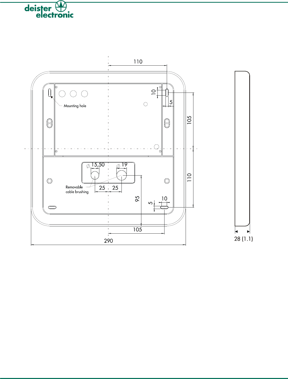
3. Mechanical Dimensions
All dimension in mm.
6rf_prm15_wi_en V10/09/08
PRM15
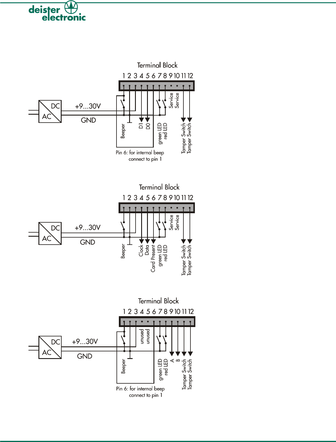
4. Wiring Diagram
4.1 2-Wire Wiegand
4.2 Magstripe Emulation/Data/Clock
4.3 RS485
8rf_prm15_wi_en V10/09/08
PRM15
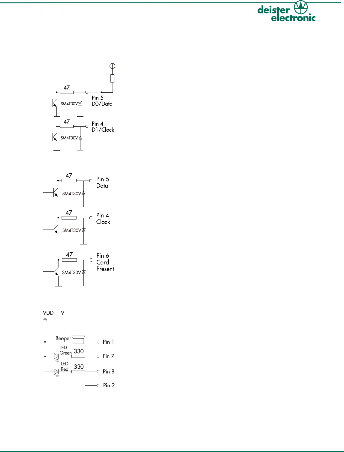
5. Interfaces
5.1 Wiegand / Data/Clock
5.2 Magstripe Emulation
5.3 Indicators
Note:
For all interfaces except RS485 the pull-ups have to be connected to the
clock and to the data lines as well. The value of the pull-ups depends on
the current and voltage which is required for the controller input.
V10/09/08 rf_prm15_wi_en 9
PRM15
Function of LEDs and Beeper:
Yellow LED:
Reader is ready to operate. LED momentarily
flashes during the reading of a card.
Green LED, red LED, Beeper:
The function of these indicators depends on how
they are connected to the host system.
5
max. 30 V
max. 20 mA
Pull-up resistor
see above
Pull-up resistor
see above
Pull-up resistor
see above
Pull-up resistor
see above
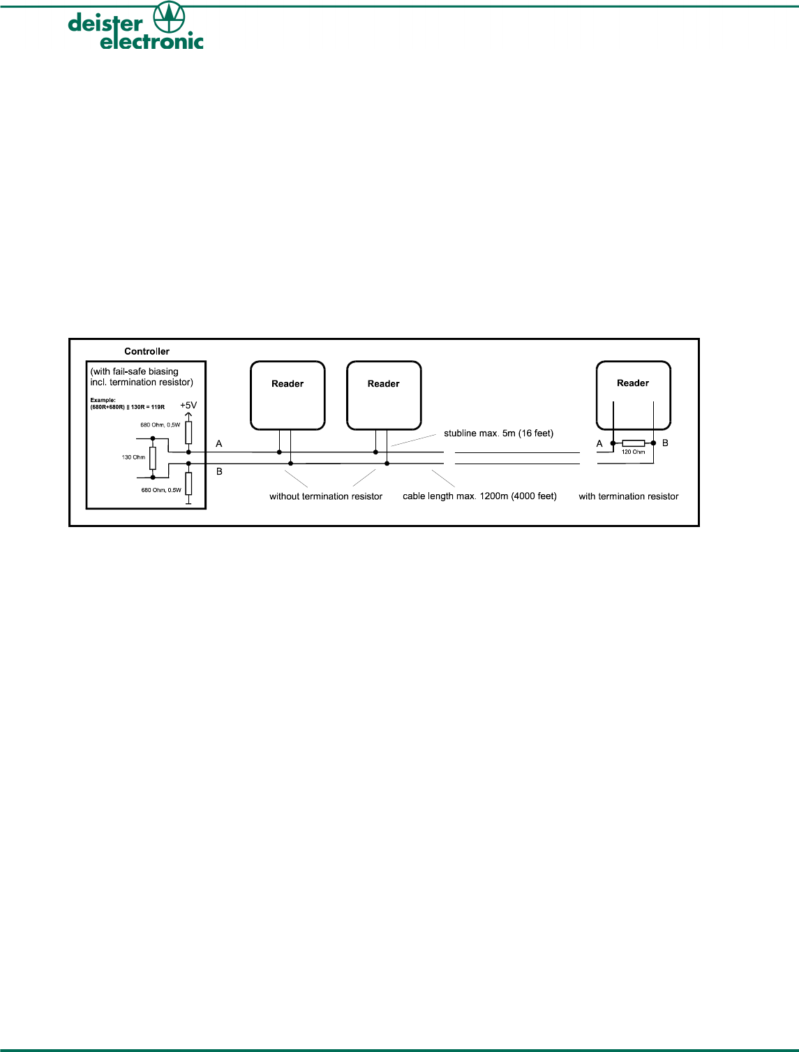
5.4 RS485 Interface
Most RS485 buses require termination resistors across the conductor pair. The need for
termination has to be checked for each installation. Especially for high data rates, steep
edges or long cables termination resistors are mandatory. Only both ends of the main
cable, i.e. at the first and the last device, require termination resistors, additional resistors
excessively load the drivers. The resistor value matches the cable´s differential mode
characteristic impedance (in most cases 100 − 120 Ω).
At the RS485 bus you need a controller with fail-safe biasing meaning a pull-up and a pull-
down resistor on the cable. The fail-safe biasing provides a known state in which there is no
active driver on the bus. Therefore this is essential regardless of data rates and length of cables.
Technical data (for baud rates up to 100 kBps):
Max. cable length: 1200 m (4000 feet)
Max. stub length: because of reflections stubs should be kept as
short as possible;
exceptions allow a length up to 5 m (16 feet)
Recommendation for the cable: twisted pair, cable-cross section at least
0.22 mm2 (AWG 24) differential-mode
characteristic impedance 100 − 120 Ω
10 rf_prm15_wi_en V10/09/08
PRM15
6. Communications Protocol
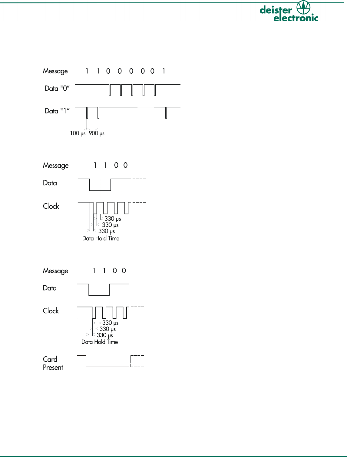
6.1 Wiegand Standard
6.2 Data/Clock
6.3 Magstripe Emulation
V10/09/08 rf_prm15_wi_en 11
PRM15

6.4 Tamper Switch
By connecting the terminal to further electrical devices it is possible for the user to control if
the cover of the PRM15 housing is open or closed. The installation can be integrated into
an alarm system in order to provide protection against tampering.
12 rf_prm15_wi_en V10/09/08
PRM15

6.5 Magstripe Interface according to ISO 7811/2-1995
Data Encoding Table
Value Bitpattern Meaning
0 0 0 0 0-1 “0”
1 1 0 0 0-0 “1”
2 0 1 0 0-0 “2”
3 1 1 0 0-1 “3”
4 0 0 1 0-0 “4”
5 1 0 1 0-1 “5”
6 0 1 1 0-1 “6”
7 1 1 1 0-0 “7”
8 0 0 0 1-0 “8”
9 1 0 0 1-1 “9”
10 (Ahex) 0 1 0 1-1 unused character
11 (Bhex) 1 1 0 1-0 start sentinel (start character)
12 (Chex) 0 0 1 1-1 unused character
13 (Dhex) 1 0 1 1-0 field separator
14 (Ehex) 0 1 1 1-0 unused character
15 (Fhex) 1 1 1 1-1 end sentinel (stop character)
The least significant bit of every digit is sent first; the fifth bit is an odd parity bit for each
group of 4 data bits.
The complete message always looks as follows:
left edge - start - data characters - end - LRC - right edge
The LRC is calculated by the following procedure:
Each of the 4 bits in the LRC character is an even parity bit of the equivalent bits in the
telegram including start and stop sentinel; i. e. the first LRC bit is an even parity bit for all
the least significant bits in the telegram and the 4th bit of the LRC is the even parity of all
the most significant bits.
The fifth bit is the odd parity of the 4 LRC bits (it is not calculated over all the parity bits).
On magstripe cards the space left and right of the information (edge) is filled with an unknown
number of zero bits (this is not a valid character as the parity is invalid). As most terminals
need some of the zero bits (known as “clocking bits” too) and do not care about additional
zero bits, deister decided to send 16 zero bits at the left edge as well as to the right edge.
V10/09/08 rf_prm15_wi_en 13
PRM15
The parity bits, the start and end characters, the LRC and the zero bits at the edge are
generated automatically by the reader.
On the one hand, they do not require space in the transponders (therefore we can encode 16
digits for the user), on the other hand this means that there will be a problem if one of the
fields is missing.
Example:
The short information “86” would be transmitted as follows:
0000000000000000-11010-00010-01101-11111-01011-0000000000000000
edge start “8” “6” stop LRC edge
A “1”-bit is transmitted as a logic low level; the falling as well as the rising edge of the clock
pulse may be used to clock in data.
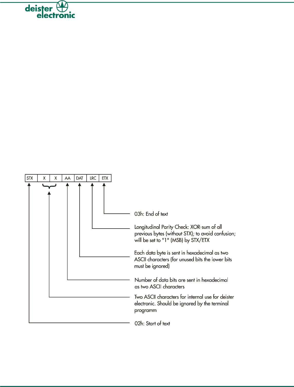
6.6 Protocol for PRM15 with RS485 (no partyline protocol)
The interface is operated using 9600 baud, 8 data bits, 2 stop bits and no parity bit.
Message Format: Example
14 rf_prm15_wi_en V10/09/08
PRM15
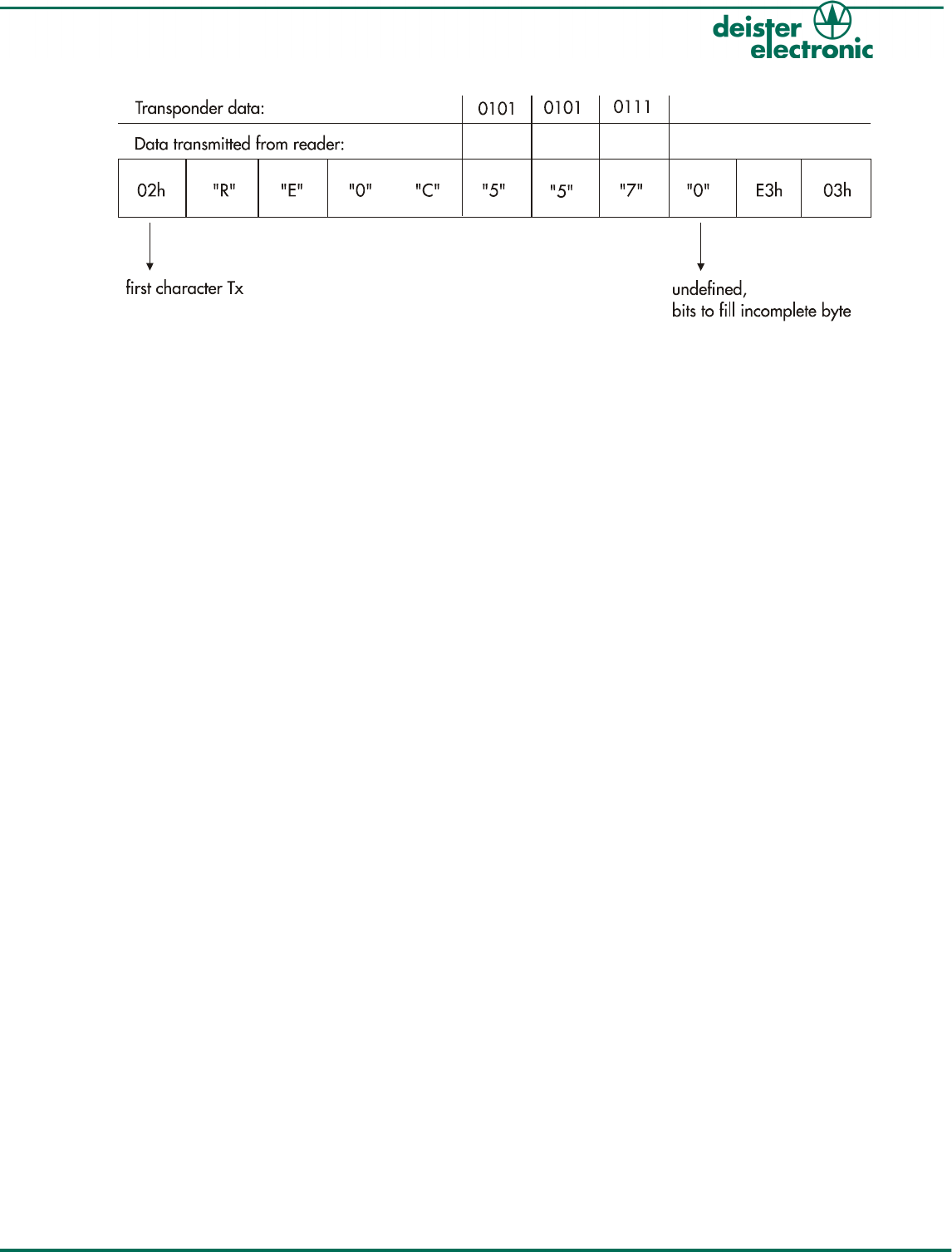
Calculation of the parity:
LRC = 80h OR [52h Å 45h Å 30h Å 43h Å 35h Å 35h Å 37h Å 30h] = E3h
(“Å” means Exlusive-OR)
V10/09/08 rf_prm15_wi_en 15
PRM15

7. Installation
7.1 Easy Trim Function (ETF)
This function allows adjustment of the reader to its environmental conditions.
The ETF is a semiautomatic function for trimming the reader to its best performance.
The ETF starts after switch S1 has been pressed (see 3.1 “Rear View”, switches).
In this mode only one of the three LEDs is blinking. The individual meaning of each LED is
as follows:
Red LED: The rotatable switch (S2) must be turned to the right.
Yellow LED: The rotatable switch (S2) must be turned to the left.
Green LED: The setting of the rotatable switch (S2) matched the best performance.
In some cases there might be two settings of the switch indicating the best performance. If
there are two possible positions for the rotatable switch (S2), we recommend to select the
position before the yellow LED has been blinking.
The ETF ends after switch S1 has been pressed again. It will also end automatically after 6
minutes.
If the reader should be mounted directly on metal surfaces (distance to metal less than 2
cm), switch S3 has to be actuated before the rotatable switch S2 is being turned.
7.2 Possible Interference Sources
Warning:
It is possible that external interference sources may influence the reading
range, e.g. monitors, switching power supplies, power cables parallel to
data cables, mounting on metal surfaces etc.
LCD monitors have a minimal influence on the reading range. In particular the reader should
only be mounted on non-metallic material, such as plastic or wood. Metal screws (M6 – ISO
1207, 4762 or 7045) for mounting of the reader have an insignificant influence on the
reading range.
The unit needs to be operated with a power source with limited power
consumption according to EN 60950-1(2001) paragraph 2.5.
Note:
With growing distance between reader and interference source the
influence will decrease.
Use only linearly regulated power supplies which are offered by deister electronic GmbH.
In order to reduce the influence of external electrical interference the cable shield has to be
connected to ground (GND) of the power supply.
16 rf_prm15_wi_en V10/09/08
PRM15
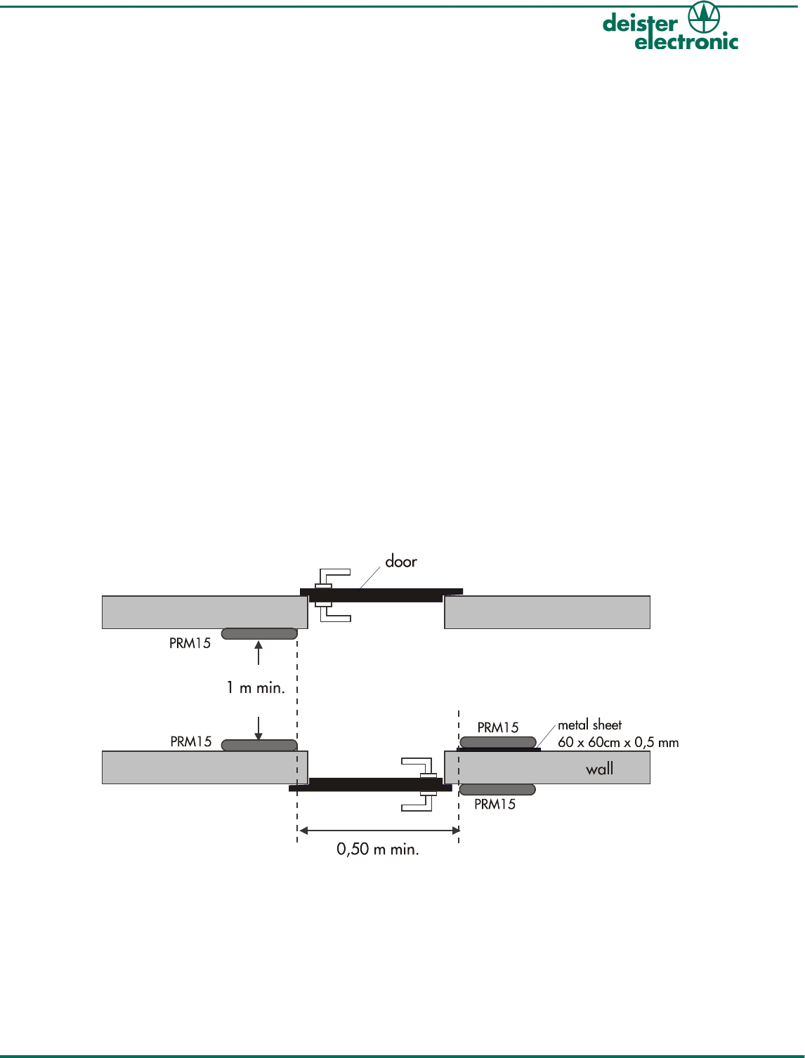
7.3 Mounting considerations
In order to ensure proper operation and an optimum reading/writing range take the
following precautions:
1.) Mount all readers before tuning any of the readers.
2.) Ensure that the back-to-back distance is at least 50 cm.
3.) Ensure that the vertical separation distance is at least 50 cm. A narrower vertical
separation gap may be used in case simultaneous reading/writing of a transponder by two
readers is acceptable.
Note:
●If a metal plate has been installed between the two readers, the back-
to-back distance may be ignored. However, the reading/writing range
will be reduced by approximately one third.
●Reduced transponder reading/writing range and the simultaneous
reading/writing of a transponder by two or more readers may result
if the readers are being installed less than 50 cm apart.
Picture: Visualization of separation distances (vertical and back-to-back)
V10/09/08 rf_prm15_wi_en 17
PRM15

8. Regulatory notices
8.1 Europe
Hereby, deister electronic GmbH declares, that this equipment - if used according to the
instructions - is in compliance with the essential requirements and other relevant provisions
of the RTTE Directive 1999/5/EG.
A full declaration of conformity can be requested at:
info@deister-gmbh.de
Approved for use in all European countries.
8.2 FCC Digital Device Limitations
Radio and Television Interference
This equipment has been tested and found to comply with the limits for a Class A digital
device, pursuant to Part 15 of the FCC rules. These limits are designed to provide
reasonable protection against harmful interference when the equipment is operated in a
commercial environment. This equipment generates, uses and can radiate radio frequency
energy and, if not installed and used in accordance with the instruction manual, may
cause harmful interference to radio communications. Operation of this equipment in a
residential area is likely to cause harmful interference, in which case the user will be
required to correct the interference at his own expense.
This device complies with Part 15 of the FCC rules. Operation is subject to the following
two conditions: (1) This device may not cause harmful interference, and (2) this device
must accept any interference received, including interference that may cause undesired
operation.
In order to maintain compliance with FCC regulations, shielded cables must be used with
this equipment. Operation with non-approved equipment or unshielded cables is likely to
result in interference to radio and television reception.
Caution! Changes or modifications not expressly approved by the manufacturer could void
the user´s authority to operate this equipment.
18 rf_prm15_wi_en V10/09/08
PRM15

Notes:
V10/09/08 rf_prm15_wi_en 19
PRM15

Germany:
deister electronic GmbH
Hermann-Bahlsen Str. 11
30890 Barsinghausen
Tel.: +49 (0) 51 05 - 51 61 11
Fax: +49 (0) 51 05 - 51 62 17
info@deister-gmbh.de
www.deister.com
deister worldwide
Canada:
Deister Electronics Inc.
1099 Kingston Road, Suite 212
Pickering, ON L1V 1B5
Tel.: +1 905 - 837 5666
Fax: +1 905 - 837 0777
info@deister-electronic.com
Japan:
deister electronic Japan, LTD.
Toshiba Hoshikawa Bldg. 4F
2-4 Kawabe-chô
Hodogaya-ku, Yokohama-shi
Kanagawa, 240-0001
Tel.: +81 (0) 45 340 1831
Fax: +81 (0) 45 340 1801
info@deister.jp
USA:
Deister Electronics USA, Inc.
9303 Grant Avenue
Manassas, VA 20110
Tel.: +1 703 - 368 2739
Fax: +1 703 - 368 9791
info@deister.com
Belgium & Luxembourg:
deister electronic office
Business Park E 19
Battelsesteenweg 455/A
2800 Mechelen
Tel.: +32 (0) 15 - 28 09 68
Fax: +32 (0) 15 - 28 09 71
info@benelux.deister.com
France:
deister electronic france
101 rue Pierre Semard
92320 Chatillon
Tel.: +33 (0) 1 47 - 35 78 78
Fax: +33 (0) 1 47 - 35 92 59
info@deister.fr
Great Britain:
deister electronic (UK) Ltd.
Stapleton Way, Enterprise Park
Spalding, Lincolnshire
PE11 3YQ
Tel.: +44 (0) 1775 - 717100
Fax: +44 (0) 1775 - 717101
info@deister.co.uk
The Netherlands:
deister electronic office
Tolnasingel 3
2411 PV Bodegraven
Tel.: +31 (0) 1726 - 32970
Fax: +31 (0) 1726 - 32971
info@nl.deister.com