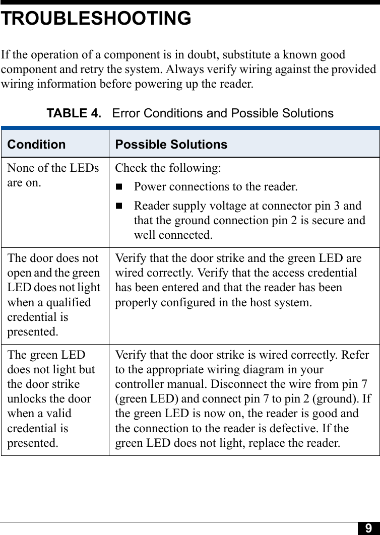
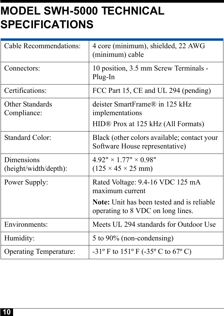
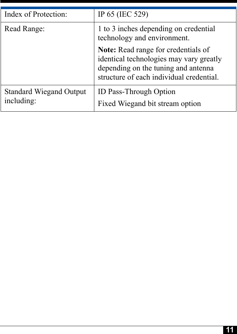
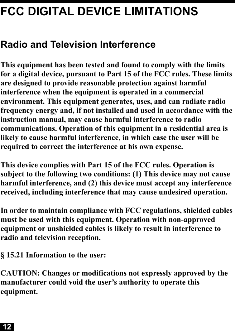
Deister Electronic PRX2SWH5000 PROXIMITY READER User Manual SWH 5000 install guide

Deister Electronic GmbH PROXIMITY READER SWH 5000 install guide

Users Manual

1Model SWH-5000Proximity 125 KHz CredentialReader Installation GuideVersion A0Part Number UM-099September 2005
2CONTENTSIntroduction . . . . . . . . . . . . . . . . . . . . . . . . . . . . . . . . . . . . . . . . . . . . . . . .  3Features  . . . . . . . . . . . . . . . . . . . . . . . . . . . . . . . . . . . . . . . . . . . . . . . . . . .  3Mounting . . . . . . . . . . . . . . . . . . . . . . . . . . . . . . . . . . . . . . . . . . . . . . . . . .  4Wiring  . . . . . . . . . . . . . . . . . . . . . . . . . . . . . . . . . . . . . . . . . . . . . . . . . . . .  6Installation Notes . . . . . . . . . . . . . . . . . . . . . . . . . . . . . . . . . . . . . . . . . . . .  8Troubleshooting . . . . . . . . . . . . . . . . . . . . . . . . . . . . . . . . . . . . . . . . . . . . .  9Model SWH-5000 Technical Specifications . . . . . . . . . . . . . . . . . . . . . .  10FCC Digital Device Limitations  . . . . . . . . . . . . . . . . . . . . . . . . . . . . . . .  12Canadian Radio Emissions Requirements . . . . . . . . . . . . . . . . . . . . . . . .  13UL Standards Compliance . . . . . . . . . . . . . . . . . . . . . . . . . . . . . . . . . . . .  13CE Marking . . . . . . . . . . . . . . . . . . . . . . . . . . . . . . . . . . . . . . . . . . . . . . .  14
3INTRODUCTIONThe SWH-5000 Proximity mullion reader will read a variety of prox cards at a frequency of 125 kHz. Compatible standards include HID and deister Prox SmartFrame®. Refer to Table 1 for a complete list of compatible standards and data.FEATURESUniversal compatibility with most 125 kHz Prox (including all HID® Prox formats)Electrical protection (reverse polarity diode protection on power lines)Data lines: high-speed transient voltage suppressor diodesIP65-rated sealed electronics for deployment in both interior and exterior environmentsTABLE 1. Compatible Credential Formats - Model SWH-5000HID® 26 Bit Other HID pass through formatsHID® Corporate 1000 deister Prox SmartFrame®HID® 36 Bit Wiegand CASI-RUSCO® Prox LiteHID® 37 Bit Wiegand Others - Future Expansion
4MOUNTINGMount the reader module directly to a metal door frame, wall, or single-gang box, and snap the front cover in place as indicated in Figure 1.FIGURE 1. Mounting Assembly
5Installation of two SWH-5000 readers side-by-side and back-to-backRead range is not affected if the center-to-center distance between two readers is greater than or equal to four (4) inches (101.6 mm). If the distance between the two readers is less than four inches, field interference between the two readers may result in a double-badge read. Two readers can simultaneously read the same badge or tag if the distance between the two readers is less than 4 inches, center-to-center. NOTEIf two readers are being placed back-to-back on a wall less than 4 inches thick, maximum performance can be achieved by using a metal separation plate and then using isolation spacers as necessary.
6WIRINGThe SWH-5000 model has ten terminals as noted in Table 2. When attaching wires to the connector, strip off only the minimum insulation required (approx. 1/8'') and push the wire into the connector until the insulation is flush or inside the connector body. This is particularly critical for outdoor readers. While the reader itself is designed and protected to IP65 standards, the cable wires can potentially corrode and short together if not carefully mounted and tightly fastened in the connector body.Table 3 indicates maximum wiring distances per Wiegand standard with the three most common gauges of cable.TABLE 2.  Connector Pins for Model SWH-5000Pin Description Pin1 External Beeper Control 6 Reserved for Future Use2 Ground 7 External Green LED Control3 Power (8 to 16 VDC) 8 External Red LED Control4 D1 Wiegand 9 No connection5 D0 Wiegand 10 No connectionTABLE 3. Maximum cable distance for 18, 20, or 22 AWG wireWire Gauge 18 AWG 20AWG 22 AWGCable Distance500 feet (152 meters)300 feet(91 meters)200 feet(61 meters)
7Beeper WiringFigure 2 shows how to wire the beeper so that it beeps when a valid card is presented to the reader. FIGURE 2. Beeper WiringTerminal Block110AC or DCRed LEDGreen LED+12VGNDBeeperD1D0For internal beep, connect Pin 6 to Pin 1 as shown
8INSTALLATION NOTESUnless otherwise specified in this manual, please follow these guidelines:1. Shielded cable is recommended in electrically noisy environments.2. You can use a local power supply for the reader. If so, don’t connect the power supply from the controller to the reader. The ground line of the local power supply must be connected to the power supply of the controller.3. The unit needs to be operated with a power source with limited power consumption according to EN 60950-1 (2001) paragraph 2.5.Das Gerät ist mit einer Stromquelle mit begrenzter Leistung nach EN 60950-1 (2001) Absatz 2.5 zu betreiben. Des Weiteren gilt die EN     60950-1 (2001) nur in Europa und nicht in den USA!    4. Use of a pull-up resistor may be required by some controllers. Consult     your controller manual.
9TROUBLESHOOTINGIf the operation of a component is in doubt, substitute a known good component and retry the system. Always verify wiring against the provided wiring information before powering up the reader.TABLE 4.  Error Conditions and Possible SolutionsCondition Possible SolutionsNone of the LEDs are on.Check the following:Power connections to the reader.Reader supply voltage at connector pin 3 and that the ground connection pin 2 is secure and well connected.The door does not open and the green LED does not light when a qualified credential is presented.Verify that the door strike and the green LED are wired correctly. Verify that the access credential has been entered and that the reader has been properly configured in the host system.The green LED does not light but the door strike unlocks the door when a valid credential is presented.Verify that the door strike is wired correctly. Refer to the appropriate wiring diagram in your controller manual. Disconnect the wire from pin 7 (green LED) and connect pin 7 to pin 2 (ground). If the green LED is now on, the reader is good and the connection to the reader is defective. If the green LED does not light, replace the reader.
10MODEL SWH-5000 TECHNICAL SPECIFICATIONSCable Recommendations:  4 core (minimum), shielded, 22 AWG (minimum) cableConnectors:  10 position, 3.5 mm Screw Terminals - Plug-InCertifications:  FCC Part 15, CE and UL 294 (pending)Other Standards Compliance:deister SmartFrame® in 125 kHz implementations HID® Prox at 125 kHz (All Formats)Standard Color:  Black (other colors available; contact your Software House representative)Dimensions(height/width/depth): 4.92" × 1.77" × 0.98" (125 × 45 × 25 mm)Power Supply: Rated Voltage: 9.4-16 VDC 125 mA maximum current Note: Unit has been tested and is reliable operating to 8 VDC on long lines.Environments:  Meets UL 294 standards for Outdoor UseHumidity:  5 to 90% (non-condensing)Operating Temperature:  -31º F to 151º F (-35º C to 67º C)
11Index of Protection:  IP 65 (IEC 529)Read Range:  1 to 3 inches depending on credential technology and environment.Note: Read range for credentials of identical technologies may vary greatly depending on the tuning and antenna structure of each individual credential.Standard Wiegand Output including:ID Pass-Through OptionFixed Wiegand bit stream option
12FCC DIGITAL DEVICE LIMITATIONSRadio and Television Interference This equipment has been tested and found to comply with the limits for a digital device, pursuant to Part 15 of the FCC rules. These limits are designed to provide reasonable protection against harmful interference when the equipment is operated in a commercial environment. This equipment generates, uses, and can radiate radio frequency energy and, if not installed and used in accordance with the instruction manual, may cause harmful interference to radio communications. Operation of this equipment in a residential area is likely to cause harmful interference, in which case the user will be required to correct the interference at his own expense. This device complies with Part 15 of the FCC rules. Operation is subject to the following two conditions: (1) This device may not cause harmful interference, and (2) this device must accept any interference received, including interference that may cause undesired operation. In order to maintain compliance with FCC regulations, shielded cables must be used with this equipment. Operation with non-approved equipment or unshielded cables is likely to result in interference to radio and television reception. § 15.21 Information to the user:  CAUTION: Changes or modifications not expressly approved by the manufacturer could void the user’s authority to operate this equipment.
13CANADIAN RADIO EMISSIONS REQUIREMENTSThis digital apparatus does not exceed the Class A limits for radio noise emissions from digital apparatus set out in the Radio Interference Regulations of the Canadian Department of Communications.Operation is subject to the following two conditions:1) This device may not cause harmful interference, and2) this device must accept any interference received, including interference    that may cause undesired operation.   Le present appareil numerique n'emet pas de bruits radioelectriques depassant les limites applicables aux appareils numeriques de la class A prescrites dans le Reglement sur le brouillage radioelectrique edicte par le ministere des Communications du Canada.UL STANDARDS COMPLIANCEThis reader has been tested by Underwriters Laboratories, Inc. for standard UL 294, Access Control System Units, but has not been tested for compliance with any particular model of controller.
14CE MARKINGHereby, Software House declares that this equipment, if used according to the instructions, is in compliance with the essential requirements and other relevant provisions of the RTTE Directive 1999/5/EC. For use in all countries of the EU. A Declaration of Conformity exists for the following Software House Multi-technology readers: To obtain a copy, contact Software House and request the “Declaration of Conformity” document for Multi-technology readers.Software House70 Westview StreetLexington, MA 02421 U.S.A.In case of alteration of the product, not agreed to by us, this declaration will lose its validity.SWH-4100 SWH-2100 SWH-1100 SWH-2000SWH-5100 SWH-4200 SWH-3100 SWH-4000SWH-1000 SWH-3000 SWH-5000This symbol indicates proof of conformity to applicable European Economic Community Council directives and harmonized standards published in the official journal of the European Communities.
15
Software House70 Westview StreetLexington, MA 02421http://www.swhouse.comFax: 781-466-9550 Phone: 781-466-6660                                                          #89602716Copyrights and TrademarksThis document contains proprietary information of Tyco International, Inc. and is furnished to its customer solely to assist in the installation, testing, operation and maintenance of the equipment described. This document may not be reproduced in whole or in part without the written approval of Tyco International.Copyright 2005 Tyco InternationalAll rights reserved.Printed in Germany.Software House is a trademark of Sensormatic Electronics Corporation.  HID, SmartFrame, and CASI-RUSCO are registered trademarks of other companies not affiliated with Sensormatic.

Navigation menu