Deister Electronic RDL150 Inductive Reader User Manual rf rdl150 RS485 em
Deister Electronic GmbH Inductive Reader rf rdl150 RS485 em
UserManual.wiki
>
Deister Electronic
>
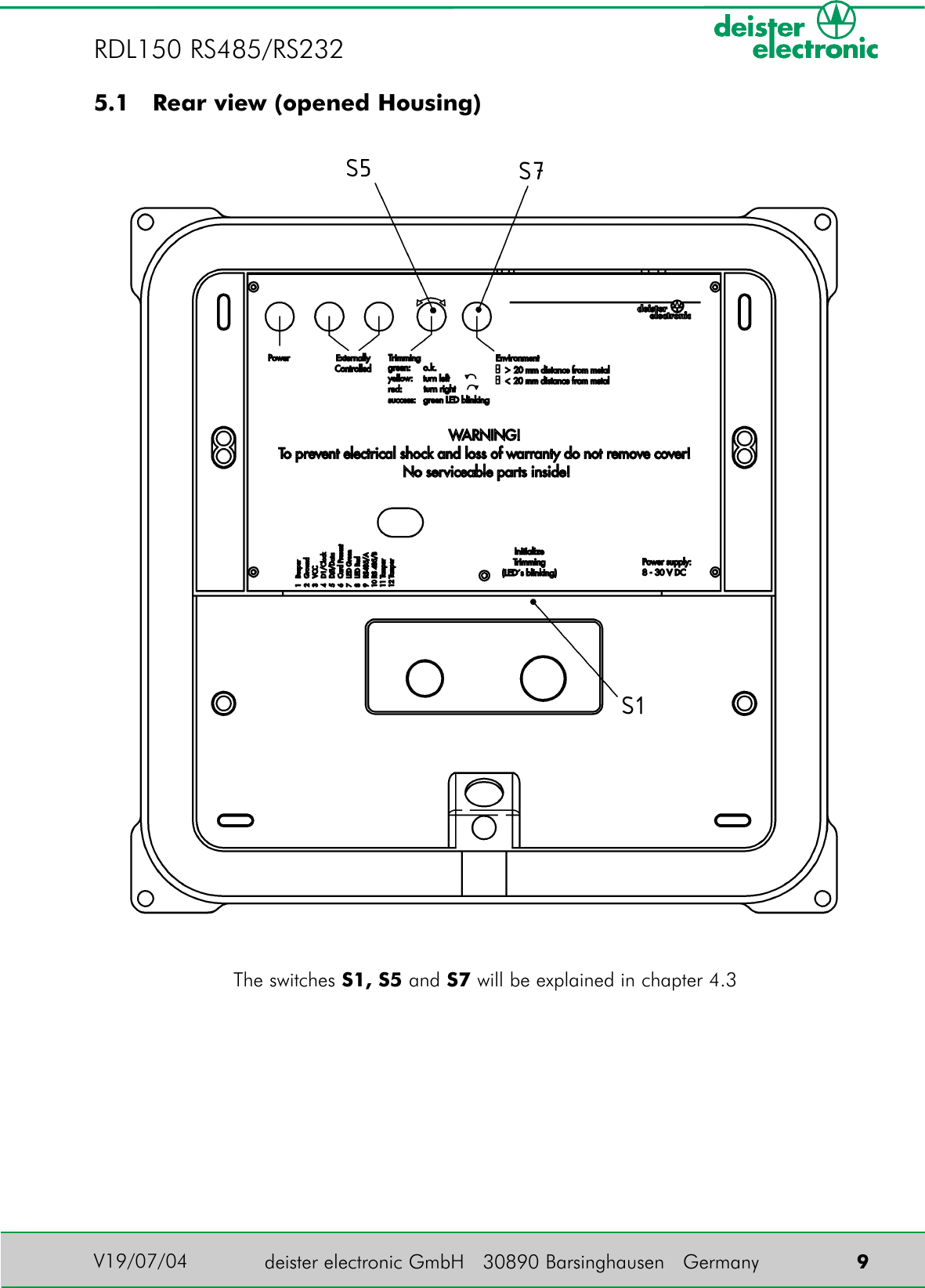
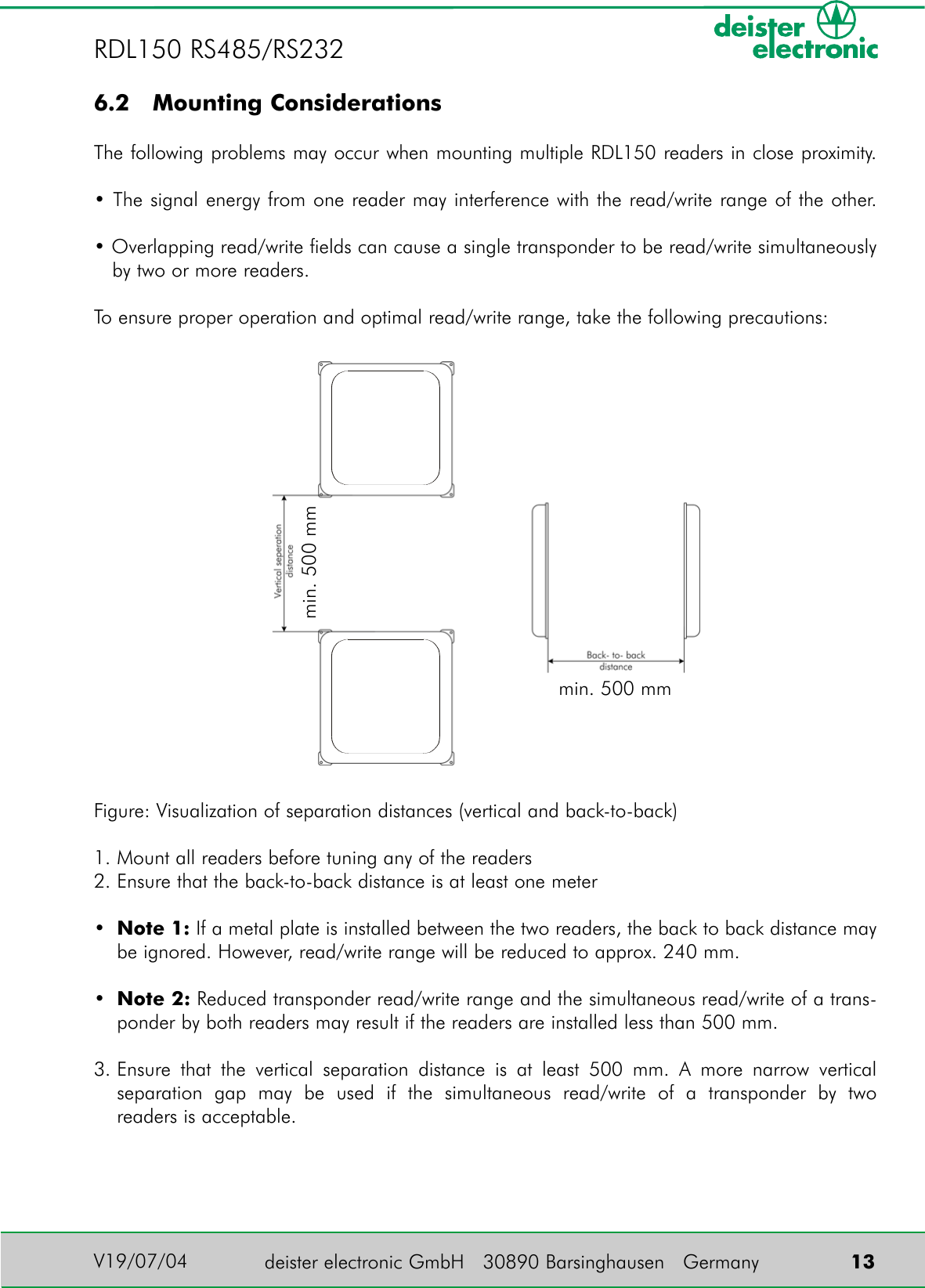
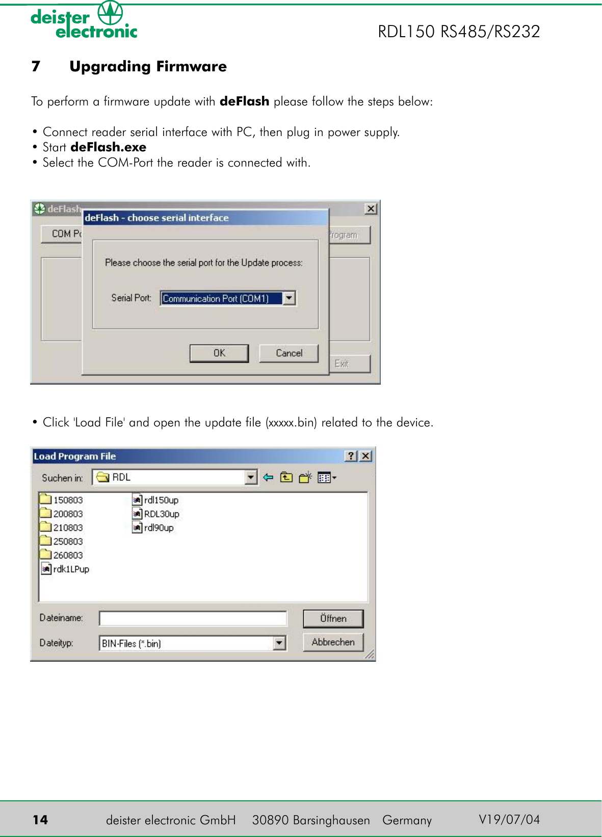
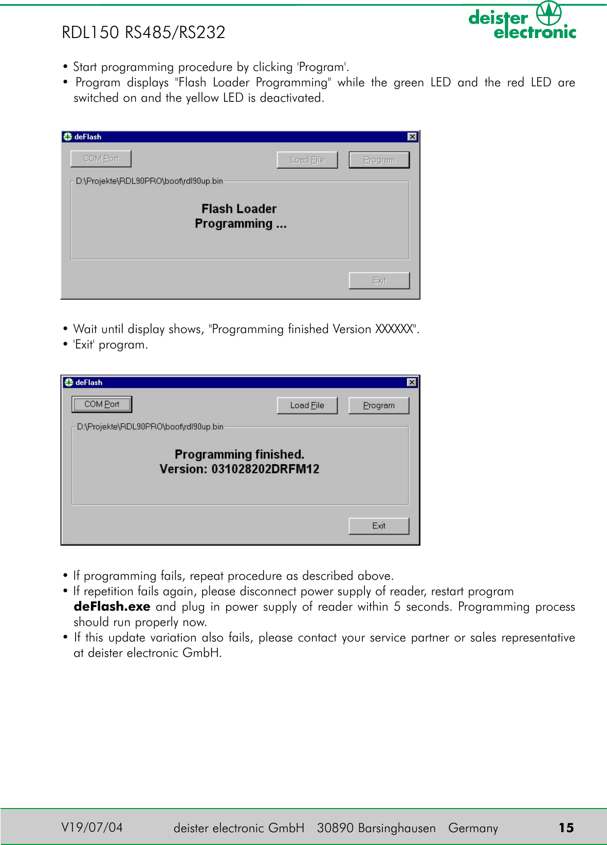
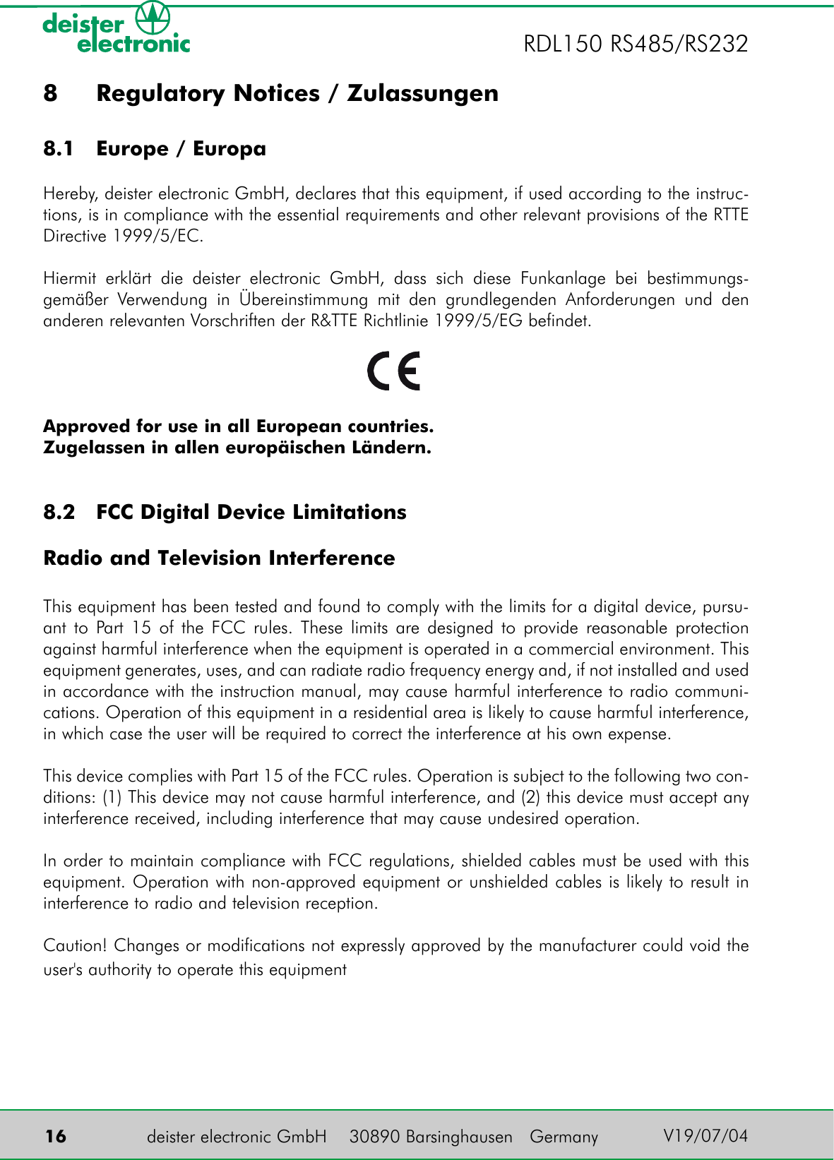
RDL150 User Manual
User Manual
Navigation menu
Upload a User Manual
Namespaces
Wiki Guide
HTML
PDF
Info
Views
User Manual
Discussion / Help
Navigation