Deister Electronic RDL150 Inductive Reader User Manual rf rdl150 RS485 em
Deister Electronic GmbH Inductive Reader rf rdl150 RS485 em
User Manual

V17/08/05
RDL150 RS485
RS232
Wiring & Installation
Instructions

deister electronic GmbH 30890 Barsinghausen Germany 2
RDL150 RS485/RS232
V19/07/04
© Copyright 2004 by deister electronic GmbH
All rights reserved. No part of this publication may be reproduced, stored in a retrieval system,
or transmitted, in any form or by any means, electronic, mechanical, photocopying, recording,
or otherwise, without prior written permission of deister electronic GmbH.
deister electronic GmbH reserves the right to make changes to any and all parts of this docu-
mentation without obligation to notify any person or entity of such changes.
August 2005 PF/HM/BF
deister electronic GmbH
Hermann-Bahlsen-Str. 11
30890 Barsinghausen
Germany
Telefon: +49 (0) 51 05 - 51 61 11
Telefax: +49 (0) 51 05 - 51 62 17
E-Mail: info@deister-gmbh.de
Web: www.deister.com

deister electronic GmbH 30890 Barsinghausen Germany 3
V19/07/04
RDL150 RS485/RS232
Contents
1 Basic Information..................................................................4
1.1 Introduction...................................................................................................... 4
1.2 Applications..................................................................................................... 4
2 Technical Data...................................................................... 5
3 Connection RDL150 with RS485............................................ 6
3.1 Connection RDL 150 with RS232........................................................................6
4 RS485 Interface..................................................................... 7
5 Mechanical Dimensions........................................................ 8
5.1 Rear view (opened housing)............................................................................... 9
5.2 LED explanation.............................................................................................. 10
5.3 Easy Trim Function........................................................................................... 11
6 Installation Instructions...................................................... 12
6.1 Possible interference sources............................................................................ 12
6.2 Mounting considerations.................................................................................. 13
7 Upgrading Firmware.......................................................... 14
8 Regulatory Notices / Zulassungen..................................... 16
8.1 Europe/Europa............................................................................................... 16
8.1 FCC Digital Device Limitations........................................................................ 16

deister electronic GmbH 30890 Barsinghausen Germany 4
RDL150 RS485/RS232
V19/07/04
1 Basic information
1.1 Introduction
The interface options enable this stationary reader with integrated controller to be connected
directly to a PC, processor or controller.
1.2 Applications
The reader was especially designed for applications where it is necessary to read and write several
transponders at the same time from different distances.
• Control of incoming goods and dispatch
• Event ticketing
• Operating data collection
• Lending processes
• Paperless operations such as electronic delivery papers, invoices, receipts

deister electronic GmbH 30890 Barsinghausen Germany 5
V19/07/04
RDL150 RS485/RS232
2 Technical Data
Dimensions: 298 x 298 x 33,5 mm
Material: ASA plastic, black
Protection type: IP 65 (IEC 529)
Operating temperature: -20 °C...+70 °C
Storage temperature: -40 °C...+70 °C
Supply voltage: +8...30 V/DC
Power consumption: approx. 2 Watt
Electrical protection: Reverse polarity diode protection on supply power lines.
High speed transient suppressor diode protection on data
lines, trigger input and switching output
Electrical connection: 1m shielded cable open wire, shield is not internally
connected
Operating frequency: 13.56 MHz
Read/write distance: up to 400 mm (depending on transponder type and the
local environment)
Data transmission speed: ca. 26 kBit/s
Reading/writing speed: < 50 ms per block
Transponder types: ISO 15693, I•CODE
Trigger input: +8...36 V/DC
Switched output: +6...32 V/DC; I< 500 mA
+32...48 V/DC; I< 300 mA
Interface: RS 232, opt. RS 485
data rate: 9600 baud, 19200 baud, 38400 baud
Anti-collision: recognition up to 30 transponders in the reading field
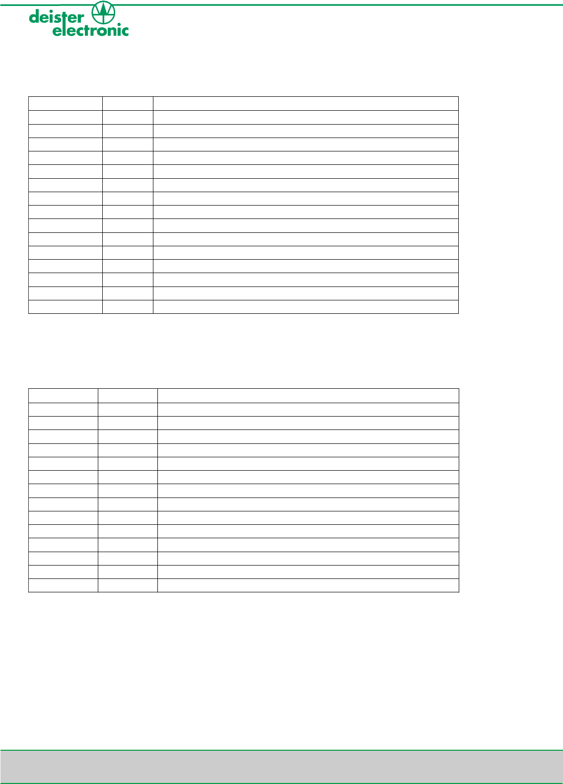
Color of cable
Signal
Function
White
V_IN
Power Supply +8...30 VDC
Brown
GND_IN
Power Supply 0 VDC
Red
VDD_SA
External power supply for galvanically isolated Output (+6...48 VDC)
Purple
SA
Galvanically isolated Output
Black
GND_SA
External power supply for galvanically isolated Output (0 VDC)
Pink
VDD_SE
Galvanically isolated Input (+5...36 VDC)
Blue
GND_SE
Galvanically isolated Input (0 VDC)
Grey
RS485_A
Noninverting Receiver Input and Driver Output
Green
RS485_B
Inverting Receiver Input and Driver Output
Yellow
GND
(internal connected with GND_IN)
3 Connection RDL150 with RS485
3.1 Connection RDL150 with RS232
deister electronic GmbH 30890 Barsinghausen Germany 6
RDL150 RS485/RS232
V19/07/04
Color of cable
Signal
Function
White
V_IN
Power Supply +8...30 VDC
Brown
GND_IN
Power Supply 0 VDC
Red
VDD_SA
External power supply for galvanically isolated Output (+6...48 VDC)
Purple
SA
Galvanically isolated Output
Black
GND_SA
External power supply for galvanically isolated Output (0 VDC)
Pink
VDD_SE
Galvanically isolated Input (+5...36 VDC)
Blue
GND_SE
Galvanically isolated Input (0 VDC)
Grey
RS232_RXD
RS232 Reader Receiving Signal
Green
RS232_TXD
RS232 Reader Transmitting Signal
Yellow
RS232_GND
RS232 GND (internal connected with GND_IN)
deister electronic GmbH 30890 Barsinghausen Germany 7
V19/07/04
RDL150 RS485/RS232
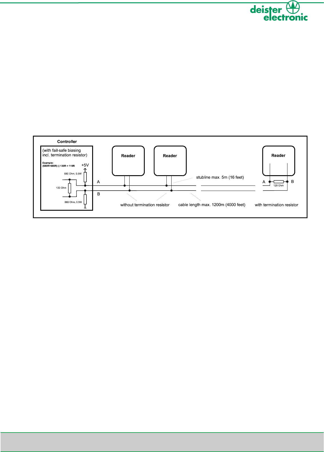
4. RS485 Interface
Most RS485-buses require termination resistors across the conductor pair. The need for termina-
tion has to be proofed for each installation. Especially for fast transitions, high data rates or long
cables the resistors are absolutely necessary. Only both ends of the main cable require termination
resistors, additional resistors excessively loads the driver. The resistor value matches the cable's
differential-mode characteristic impedance (100-120 Ohm).
At the RS485-bus you need a controller with fail-safe biasing, meaning a pull-up and a pull-down
resistor on the cable. The fail-safe biasing provides a known state in which there is no active
driver on the bus and therefore it is essential, independent from data rates and length of the cable.
(Bus with RS485 interface)
Technical data (for baud rates up to 100 kHz):
Max. cable length: 1200m (4000 feet)
Max. stub length: because of reflections stubs should be as short as possible
Exceptions allow a length up to 5 m (16 feet)
Recommendation
for the cable: twisted pair, cable-cross-section at least 0,22mm² (AWG 24)
differential-mode characteristic impedance 100-120 Ohm
deister electronic GmbH 30890 Barsinghausen Germany 8
RDL150 RS485/RS232
V19/07/04
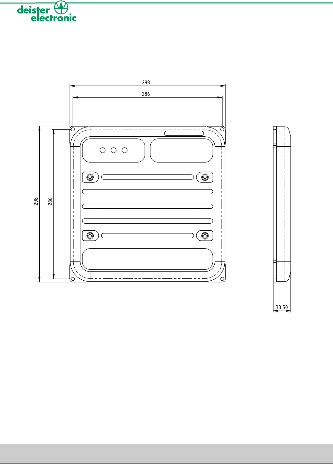
5 Mechanical Dimensions
All dimensions in mm
Status: red LED, displays errors and error telegrams or valid data
Read: green LED, displays succesful reading of a transponder
Power: yellow LED, always lighting if power supply is connected
Further explanation on page 10.
deister electronic GmbH 30890 Barsinghausen Germany 9
V19/07/04
RDL150 RS485/RS232
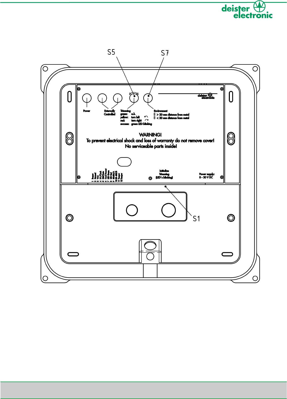
5.1 Rear view (opened Housing)
The switches S1, S5 and S7 will be explained in chapter 4.3

deister electronic GmbH 30890 Barsinghausen Germany 10
RDL150 RS485/RS232
V19/07/04
5.2 LED Explanation
1) Yellow LED: Line voltage indicator
After connecting the power supply, the device shows it is ready to operate by permanently
activating the yellow LED. If a transponder is read, the yellow LED turns off for a moment.
2) Green LED: Read indicator
If a transponder data was read, the answer telegram is sent and the reader activates
the green LED for about 50 ms. No visual activity of LED during write instructions.
3) Red LED: Status indicator
Displays error telegrams.The LED activates for about 200ms on the following events:
• Communication error telegrams
• Non executable commands
• If the reader is set to polling mode (see Rdemo description, chapter xx) and a transponder
is identified, the red LED lights up while the “valid data” is not polled by the host system.
4) General status indicator:
The green LED and the red LED are activated while the yellow LED is deactivated.
This occurs during:
• The start up phase after switch on the reader
• While updating the firmware
The description for upgrading the firmware will be found in chapter 6
• Undervoltage operation of the reader (e.g. U < 8 V/DC)

deister electronic GmbH 30890 Barsinghausen Germany 11
V19/07/04
RDL150 RS485/RS232
5.3 Easy Trim Function (ETF)
This function allows adjusting the reader to its environmental conditions.
The ETF is a semiautomatic function for trimming the reader to its best performance.
The ETF starts if switch S1 is pressed.
In this mode only one of the three LEDs is blinking. The individual meaning of each LED is:
Red LED: The rotatable switch (S5) must be turned to the right
Yellow LED: The rotatable switch (S5) must be turned to the left
Green LED: The setting of the rotatable switch (S5) matched the best performance.
It could be possible that there are two settings of the switch that match the best performance.
If there are two possible positions of the rotatable switch (S5), it is better to choose the position
before the yellow LED is blinking.
The ETF ends after switch S1 is pressed again. It also ends after 6 minutes.
If the reader should be mounted directly on metal ground (distance to metal is lower than
2 cm) the switch S7 must be actuated before the rotatable switch is turned.

deister electronic GmbH 30890 Barsinghausen Germany 12
RDL150 RS485/RS232
V19/07/04
6 Installation Instructions
6.1 Possible Interference Sources
*Warning:
It is possible that external interference sources will influence the read range, e.g. monitors,
switching power supplies, power cables parallel to data cables, mounting on metal etc.
)Note:
With growing distance between reader and interference source the influence decreases.
LCD monitors have a minimal influence on the read range. In particular the reader should be
mounted on non-metallic material, such as plastic or wood. Metal screws (M6 - ISO 1207, 4762
or 7045) for mounting the reader have an insignificant influence on the read range.
Use only regulated power supplies. deister electronic GmbH offers suitable power supplies.
To reduce the influence of external electrical interference, connect the cable shield to ground
(GND) of the power supply.
deister electronic GmbH 30890 Barsinghausen Germany 13
V19/07/04
RDL150 RS485/RS232
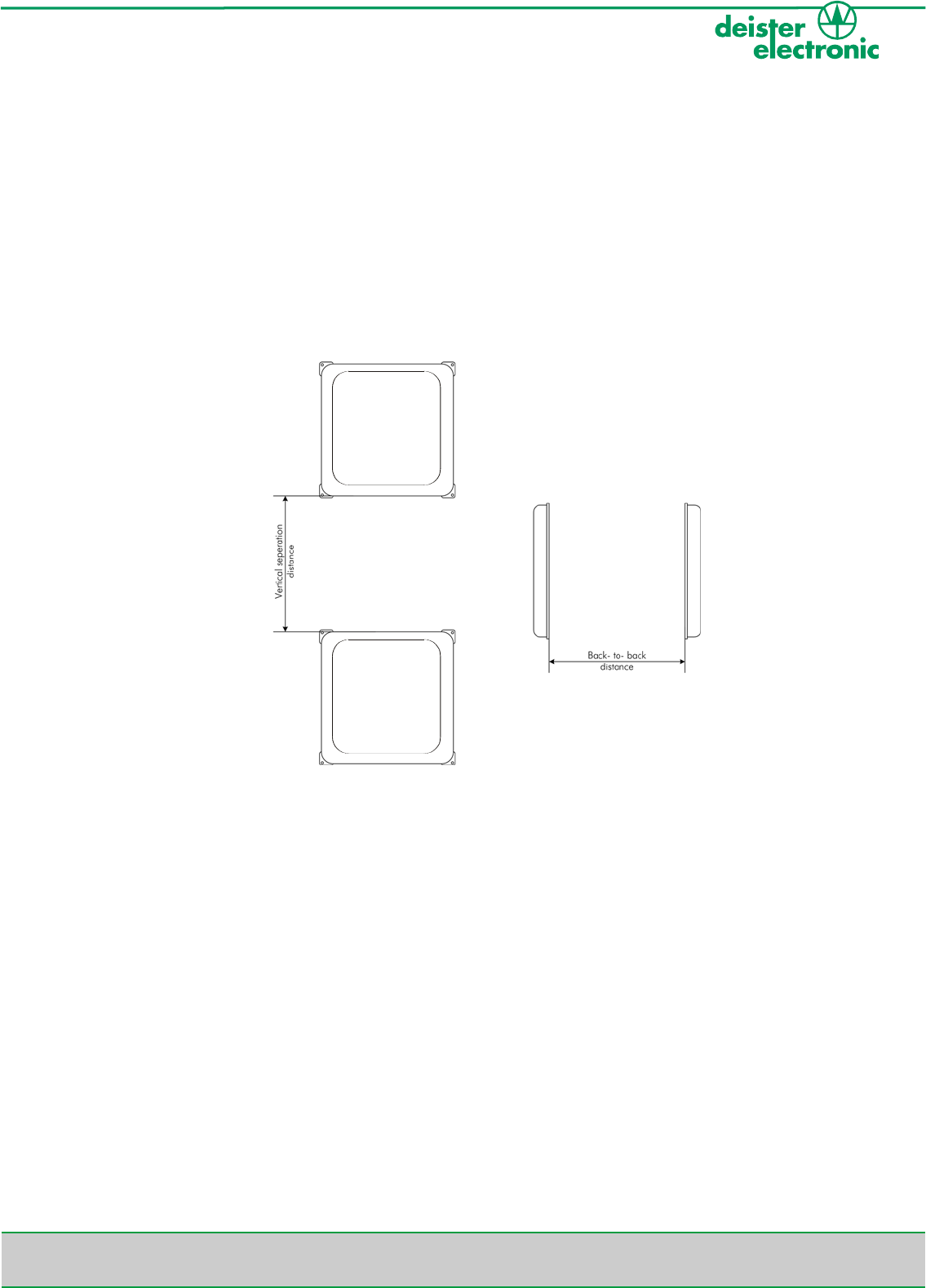
6.2 Mounting Considerations
The following problems may occur when mounting multiple RDL150 readers in close proximity.
• The signal energy from one reader may interference with the read/write range of the other.
• Overlapping read/write fields can cause a single transponder to be read/write simultaneously
by two or more readers.
To ensure proper operation and optimal read/write range, take the following precautions:
Figure: Visualization of separation distances (vertical and back-to-back)
1. Mount all readers before tuning any of the readers
2. Ensure that the back-to-back distance is at least one meter
• Note 1: If a metal plate is installed between the two readers, the back to back distance may
be ignored. However, read/write range will be reduced to approx. 240 mm.
• Note 2: Reduced transponder read/write range and the simultaneous read/write of a trans-
ponder by both readers may result if the readers are installed less than 500 mm.
3. Ensure that the vertical separation distance is at least 500 mm. A more narrow vertical
separation gap may be used if the simultaneous read/write of a transponder by two
readers is acceptable.
min. 500 mm
min. 500 mm
deister electronic GmbH 30890 Barsinghausen Germany 14
RDL150 RS485/RS232
V19/07/04
7 Upgrading Firmware
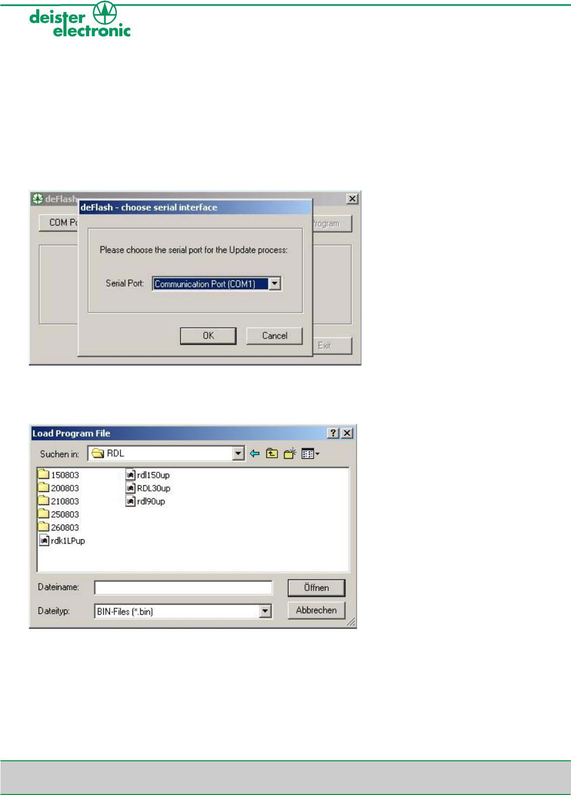
To perform a firmware update with deFlash please follow the steps below:
• Connect reader serial interface with PC, then plug in power supply.
• Start deFlash.exe
• Select the COM-Port the reader is connected with.
• Click 'Load File' and open the update file (xxxxx.bin) related to the device.
deister electronic GmbH 30890 Barsinghausen Germany 15
V19/07/04
RDL150 RS485/RS232
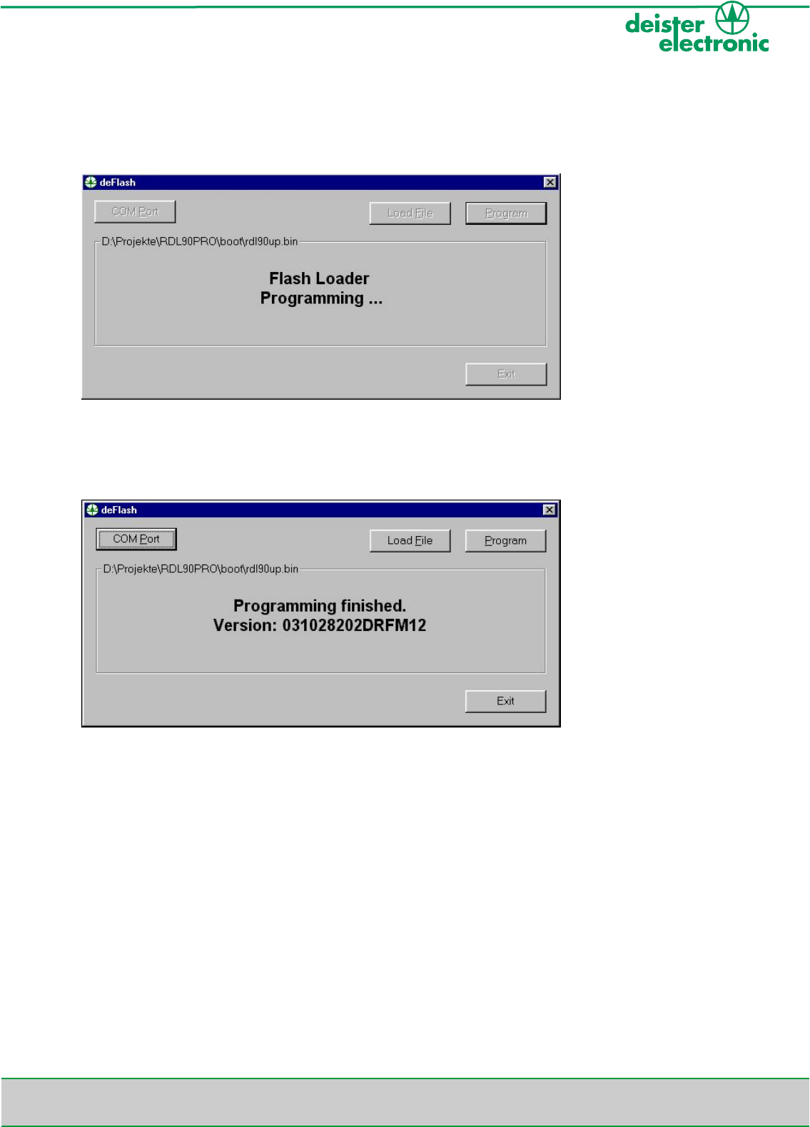
• Start programming procedure by clicking 'Program'.
• Program displays "Flash Loader Programming" while the green LED and the red LED are
switched on and the yellow LED is deactivated.
• Wait until display shows, "Programming finished Version XXXXXX".
• 'Exit' program.
• If programming fails, repeat procedure as described above.
• If repetition fails again, please disconnect power supply of reader, restart program
deFlash.exe and plug in power supply of reader within 5 seconds. Programming process
should run properly now.
• If this update variation also fails, please contact your service partner or sales representative
at deister electronic GmbH.
deister electronic GmbH 30890 Barsinghausen Germany 16
RDL150 RS485/RS232
V19/07/04
8 Regulatory Notices / Zulassungen
8.1 Europe / Europa
Hereby, deister electronic GmbH, declares that this equipment, if used according to the instruc-
tions, is in compliance with the essential requirements and other relevant provisions of the RTTE
Directive 1999/5/EC.
Hiermit erklärt die deister electronic GmbH, dass sich diese Funkanlage bei bestimmungs-
gemäßer Verwendung in Übereinstimmung mit den grundlegenden Anforderungen und den
anderen relevanten Vorschriften der R&TTE Richtlinie 1999/5/EG befindet.
Approved for use in all European countries.
Zugelassen in allen europäischen Ländern.
8.2 FCC Digital Device Limitations
Radio and Television Interference
This equipment has been tested and found to comply with the limits for a digital device, pursu-
ant to Part 15 of the FCC rules. These limits are designed to provide reasonable protection
against harmful interference when the equipment is operated in a commercial environment. This
equipment generates, uses, and can radiate radio frequency energy and, if not installed and used
in accordance with the instruction manual, may cause harmful interference to radio communi-
cations. Operation of this equipment in a residential area is likely to cause harmful interference,
in which case the user will be required to correct the interference at his own expense.
This device complies with Part 15 of the FCC rules. Operation is subject to the following two con-
ditions: (1) This device may not cause harmful interference, and (2) this device must accept any
interference received, including interference that may cause undesired operation.
In order to maintain compliance with FCC regulations, shielded cables must be used with this
equipment. Operation with non-approved equipment or unshielded cables is likely to result in
interference to radio and television reception.
Caution! Changes or modifications not expressly approved by the manufacturer could void the
user's authority to operate this equipment

deister electronic GmbH 30890 Barsinghausen Germany 17
V19/07/04
RDL150 RS485/RS232
Notes:

deister electronic GmbH 30890 Barsinghausen Germany 18
RDL150 RS485/RS232
V19/07/04
Notes:

deister electronic GmbH 30890 Barsinghausen Germany 19
V19/07/04
RDL150 RS485/RS232
Notes:

Great Britain:
deister electronic (UK) Ltd.
Camelgate,
Spalding
Lincolnshire PE12 6ET
Tel.: +44 (0) 1775 - 717100
Fax: +44 (0) 1775 - 717101
info@deister.co.uk
USA:
deister electronic USA Inc.
9303 Grant Avenue
Manassas, VA 22110
Tel.: +1 703 - 368 2739
Fax: +1 703 - 368 9791
info@deister.com
Canada:
deister electronic Inc.
1099 Kingston Road, Suit 212
Pickering ON. L1V 1B5
Tel.: +1 905 - 837 5666
Fax: +1 905 - 837 0777
info@deister-electronic.com
Belgium & Luxemburg:
deister electronic office
Business Park E 19
Battelsesteenweg 455/A
2800 Mechelen
Tel.: +32 (0) 15 - 28 09 68
Fax: +32 (0) 15 - 28 09 71
info@benelux.deister.com
The Netherlands:
deister electronic office
Tolnasingel 3
2411 PV Bodegraven
Tel.: +31 (0) 1726 - 32970
Fax: +31 (0) 1726 - 32971
info@nl.deister.com
France:
deister electronic france
101 rue Pierre Semard
92320 Chatillon
Tel.: +33 (0) 1 47 - 35 78 78
Fax: +33 (0) 1 47 - 35 92 59
info@deister.fr
Germany:
deister electronic GmbH
Hermann-Bahlsen-Str. 11
30890 Barsinghausen
Tel.: +49 (0) 51 05 - 51 61 11
Fax: +49 (0) 51 05 - 51 62 17
info@deister-gmbh.de
www.deister.com
deister worldwide