Deister Electronic TSU25UDL250 UHF RFID Reader User Manual
Deister Electronic GmbH UHF RFID Reader Users Manual
UserManual.wiki
>
Deister Electronic
>
TSU25UDL250 User Manual
Users Manual
Navigation menu
Upload a User Manual
Namespaces
Wiki Guide
HTML
PDF
Info
Views
User Manual
Discussion / Help
Navigation
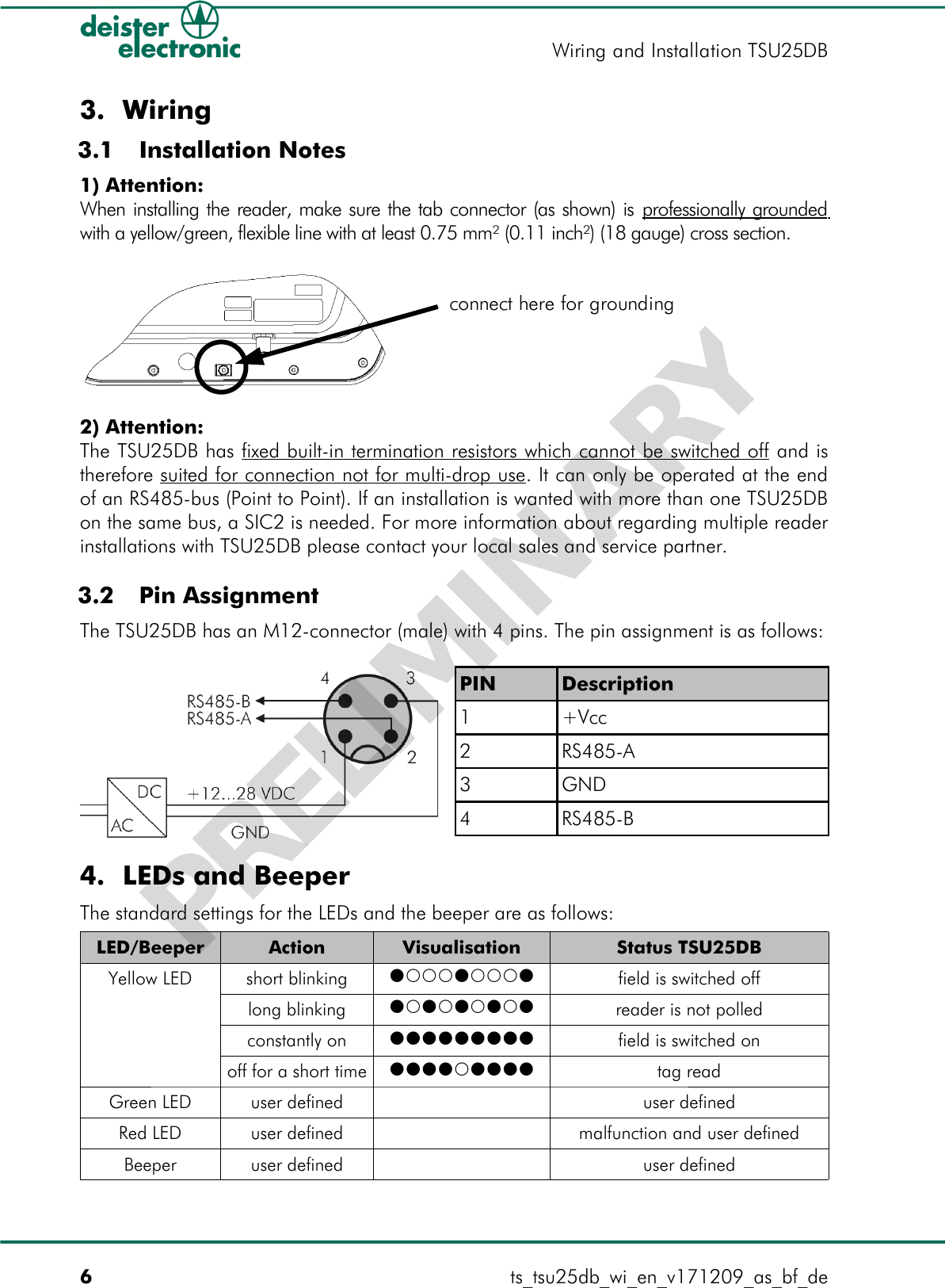
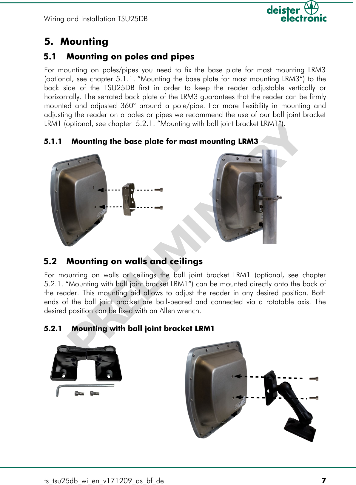
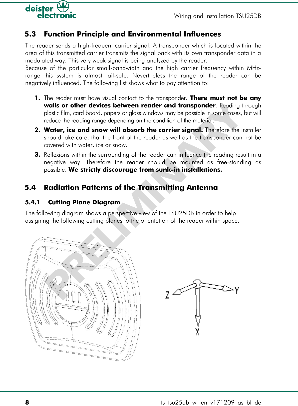
![2. Mechanical DimensionsAll dimensions in mm [inches]. 2.1 Side View 2.2 Front View 2.3 Rear Viewts_tsu25db_wi_en_v171209_as_bf_de 5Wiring and Installation TSU25DBAttention! M6 Metric Screws only! PRELIMINARY](https://usermanual.wiki/Deister-Electronic/TSU25UDL250/User-Guide-1216878-Page-5.png)