Deister Electronic TSU25UDL250 UHF RFID Reader User Manual
Deister Electronic GmbH UHF RFID Reader Users Manual
Users Manual

TSU25DB
TSU25DB-PIR
Long Distance Reader
Wiring and Installation
Instructions
ts_tsu25db_wi_en_v171209_as_bf_de
Art. #896130
PRELIMINARY

DB
Regulatory Notices
Europe
Hereby, deister electronic GmbH declares that this equipment - if used according to the
instructions - is in compliance with the essential requirements and other relevant provisions
of the RTTE Directive 1999/5/EC.
A full declaration of conformity can be requested at:
info@deister-gmbh.de
Approved for use in all European countries.
FCC Digital Device Limitations
Radio and Television Interference
This equipment has been tested and found to comply with the limits for a Class A digital
device, pursuant to Part 15 of the FCC rules. These limits are designed to provide
reasonable protection against harmful interference when the equipment is operated in a
commercial environment. This equipment generates, uses and can radiate radio frequency
energy and, if not installed and used in accordance with the instruction manual, may
cause harmful interference to radio communications. Operation of this equipment in a
residential area is likely to cause harmful interference, in which case the user will be
required to correct the interference at his own expense.
This device complies with Part 15 of the FCC rules. Operation is subject to the following
two conditions: (1) This device may not cause harmful interference, and (2) this device
must accept any interference received, including interference that may cause undesired
operation.
In order to maintain compliance with FCC regulations, shielded cables must be used with
this equipment. Operation with non-approved equipment or unshielded cables is likely to
result in interference to radio and television reception.
Caution! Changes or modifications not expressly approved by the manufacturer could void
the user´s authority to operate this equipment.
2ts_tsu25db_wi_en_v171209_as_bf_de
Wiring and Installation TSU25DB
PRELIMINARY

FCC Notice
To comply with FCC Part 15 rules in the United States, the system must be professionally
installed to ensure compliance with the Part 15 certification. It is the responsibility of the
operator and professional installer to ensure that only certified systems are deployed in the
United States. The use of the system in any other combination (such as co-located
antennas transmitting the same information) is expressly forbidden.
FCC Radiation Exposure Statement
This equipment complies with the FCC radiation exposure limits set forth for an
uncontrolled environment. This equipment should be installed and operated with minimum
distance of 20 cm between the radiator and the human body.
Industry Canada
This Class A digital apparatus complies with Canadian ICES-003.
Cet appareil numérique de la classe A est conforme à la norme NMB-003 du Canada.
© Copyright 2009 by deister electronic GmbH
Disclaimer
deister electronic GmbH is not able to supervise the observance of the instructions given in this
manual as well as the conditions and methods used during installation, operation and
maintenance of the electronic devices and components respectively. Therefore we disclaim
liability and reject responsibility for any losses, damages or costs that are caused by
misapplication, installation, handling errors or faulty operation or related to the above in any
other way. All our products are subject to current advancement, therefore we reserve the right for
modifications without prior notice.
All rights reserved. No part of this publication may be reproduced, stored in a retrieval system,
or transmitted, in any form or by any means, electronic, mechanical, photocopying, recording,
or otherwise, without prior written permission of deister electronic GmbH.
deister electronic GmbH reserves the right to make changes to any and all parts of this
documentation without obligation to notify any person or entity of such changes.
Dezember 2009 IO/DE/SK/MP
deister electronic GmbH
Hermann-Bahlsen Str. 11
30890 Barsinghausen
Germany
Phone: +49 (0) 51 05 - 51 61 11
Fax: +49 (0) 51 05 - 51 62 17
E-Mail: info.de@deister.com
Web: www.deister.com
ts_tsu25db_wi_en_v171209_as_bf_de 3
Wiring and Installation TSU25DB
PRELIMINARY

DB
1. Technical Data
Dimensions:
mm (inch) W x H x D 278 x 238 x 86 (11 x 9.4 x 3.4)
Weight:
kg (lbs) 2,5 (5.5)
Housing Material: ABS/PMMA, Al
Protection Class: IP 65
Operating Temperature: -30 °C...+60 °C
-22 °F...+140 °F
Relative Humidity: 5 %...95 %, non-condensing
Power Requirement: 12...28 VDC / max. 1 A
Transmission Frequency: 865 – 868 MHz (EU) or
902 – 928 MHz (US) or
953 – 956 MHz (JP)
Radiated Transmit Power: max. 1.6 W E.R.P.
(ETSI EN 302 208) or
max. 2.6 W E.I.R.P.
(FCC Part 15), configurable
Transponder Protocols: ISO18000-6 C (EPC Class1 Gen2)
Reading Distance:
in m (ft.) up to 4 (up to 13)
Interface: RS485 with deBus protocol
Electrical Connection: M12-connector with 4 Pins
Conformity: EN 50346
EN 301489
Air interface (EU) EN 302208 v1.2
Air interface (US) FCC Part 15
4ts_tsu25db_wi_en_v171209_as_bf_de
Wiring and Installation TSU25DB
PRELIMINARY
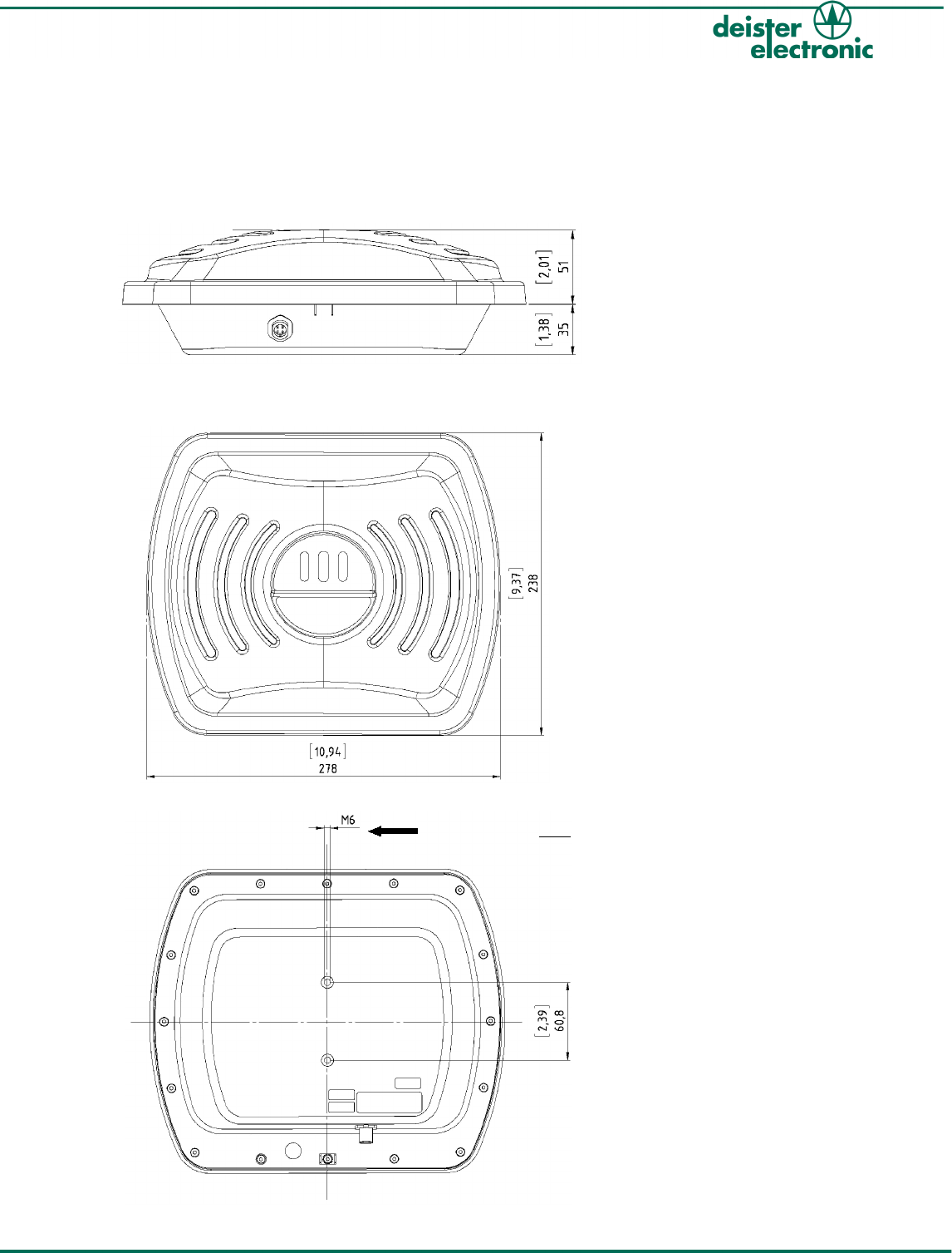
2. Mechanical Dimensions
All dimensions in mm [inches].
2.1 Side View
2.2 Front View
2.3 Rear View
ts_tsu25db_wi_en_v171209_as_bf_de 5
Wiring and Installation TSU25DB
Attention! M6 Metric Screws only!
PRELIMINARY
DB
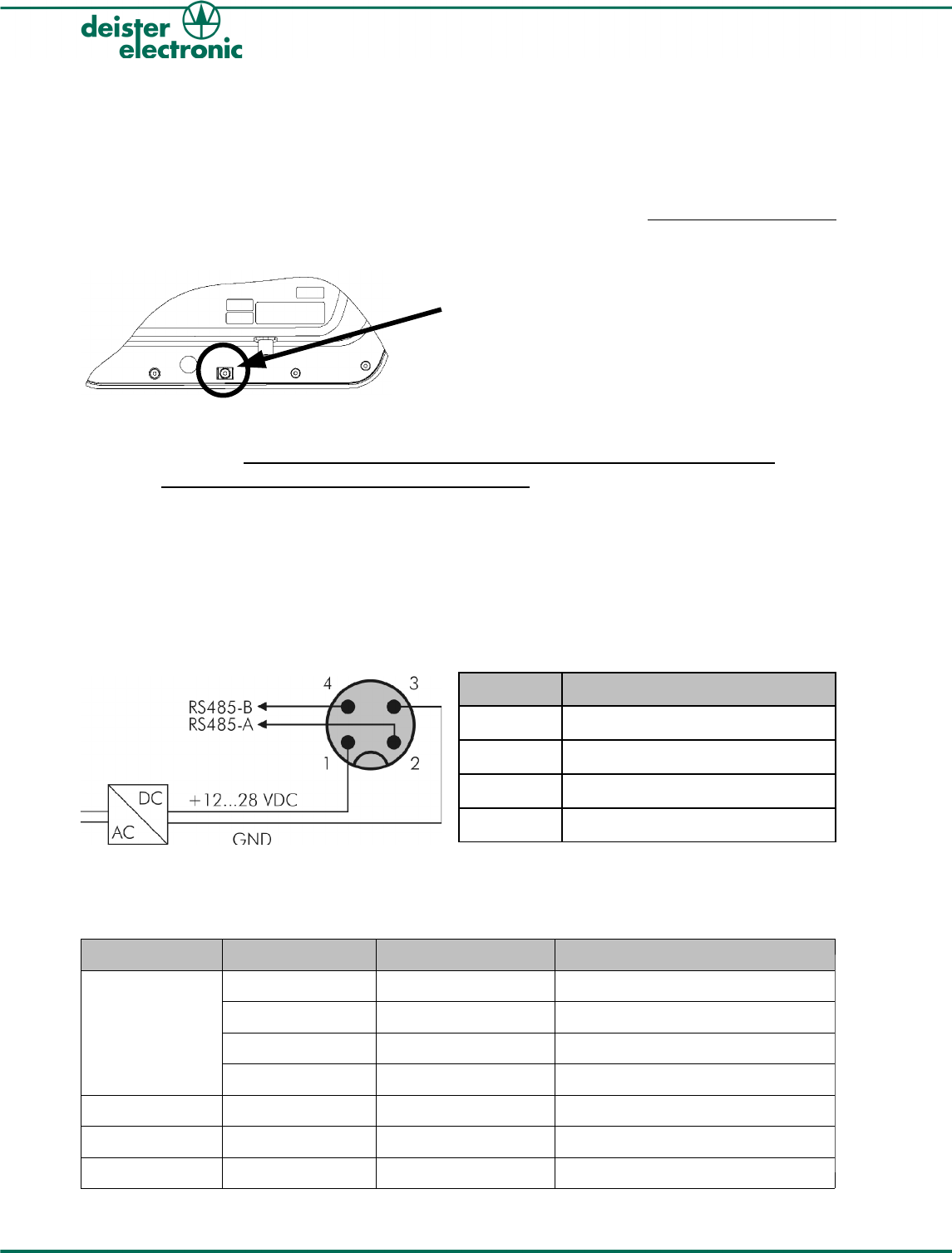
3. Wiring
3.1 Installation Notes
1) Attention:
When installing the reader, make sure the tab connector (as shown) is professionally grounded
with a yellow/green, flexible line with at least 0.75 mm² (0.11 inch²) (18 gauge) cross section.
2) Attention:
The TSU25DB has fixed built-in termination resistors which cannot be switched off and is
therefore suited for connection not for multi-drop use. It can only be operated at the end
of an RS485-bus (Point to Point). If an installation is wanted with more than one TSU25DB
on the same bus, a SIC2 is needed. For more information about regarding multiple reader
installations with TSU25DB please contact your local sales and service partner.
3.2 Pin Assignment
The TSU25DB has an M12-connector (male) with 4 pins. The pin assignment is as follows:
PIN Description
1 +Vcc
2 RS485-A
3 GND
4 RS485-B
4. LEDs and Beeper
The standard settings for the LEDs and the beeper are as follows:
LED/Beeper Action Visualisation Status TSU25DB
Yellow LED short blinking field is switched off
long blinking reader is not polled
constantly on field is switched on
off for a short time tag read
Green LED user defined user defined
Red LED user defined malfunction and user defined
Beeper user defined user defined
6ts_tsu25db_wi_en_v171209_as_bf_de
Wiring and Installation TSU25DB
connect here for grounding
PRELIMINARY
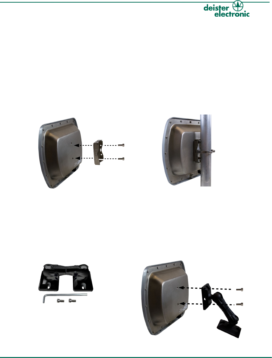
5. Mounting
5.1 Mounting on poles and pipes
For mounting on poles/pipes you need to fix the base plate for mast mounting LRM3
(optional, see chapter 5.1.1. “Mounting the base plate for mast mounting LRM3“) to the
back side of the TSU25DB first in order to keep the reader adjustable vertically or
horizontally. The serrated back plate of the LRM3 guarantees that the reader can be firmly
mounted and adjusted 360° around a pole/pipe. For more flexibility in mounting and
adjusting the reader on a poles or pipes we recommend the use of our ball joint bracket
LRM1 (optional, see chapter 5.2.1. “Mounting with ball joint bracket LRM1“).
5.1.1 Mounting the base plate for mast mounting LRM3
5.2 Mounting on walls and ceilings
For mounting on walls or ceilings the ball joint bracket LRM1 (optional, see chapter
5.2.1. “Mounting with ball joint bracket LRM1“) can be mounted directly onto the back of
the reader. This mounting aid allows to adjust the reader in any desired position. Both
ends of the ball joint bracket are ball-beared and connected via a rotatable axis. The
desired position can be fixed with an Allen wrench.
5.2.1 Mounting with ball joint bracket LRM1
ts_tsu25db_wi_en_v171209_as_bf_de 7
Wiring and Installation TSU25DB
PRELIMINARY
DB
5.3 Function Principle and Environmental Influences
The reader sends a high-frequent carrier signal. A transponder which is located within the
area of this transmitted carrier transmits the signal back with its own transponder data in a
modulated way. This very weak signal is being analyzed by the reader.
Because of the particular small-bandwidth and the high carrier frequency within MHz-
range this system is almost fail-safe. Nevertheless the range of the reader can be
negatively influenced. The following list shows what to pay attention to:
1. The reader must have visual contact to the transponder. There must not be any
walls or other devices between reader and transponder. Reading through
plastic film, card board, papers or glass windows may be possible in some cases, but will
reduce the reading range depending on the condition of the material.
2. Water, ice and snow will absorb the carrier signal. Therefore the installer
should take care, that the front of the reader as well as the transponder can not be
covered with water, ice or snow.
3. Reflexions within the surrounding of the reader can influence the reading result in a
negative way. Therefore the reader should be mounted as free-standing as
possible. We strictly discourage from sunk-in installations.
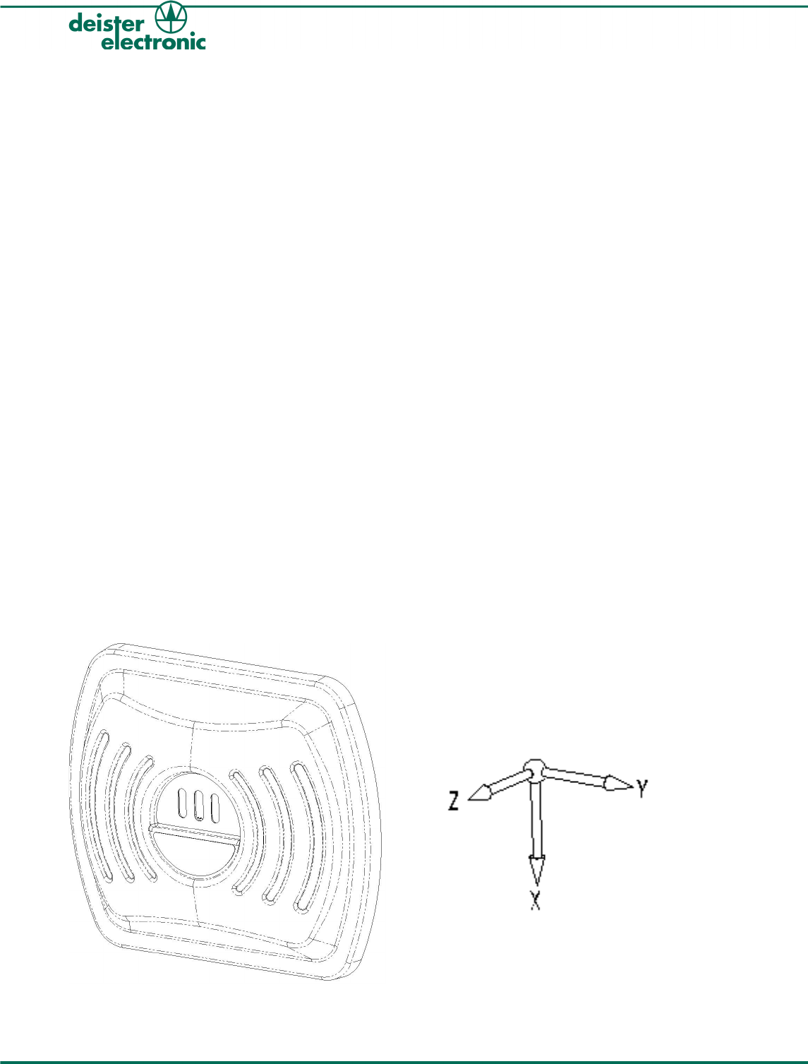
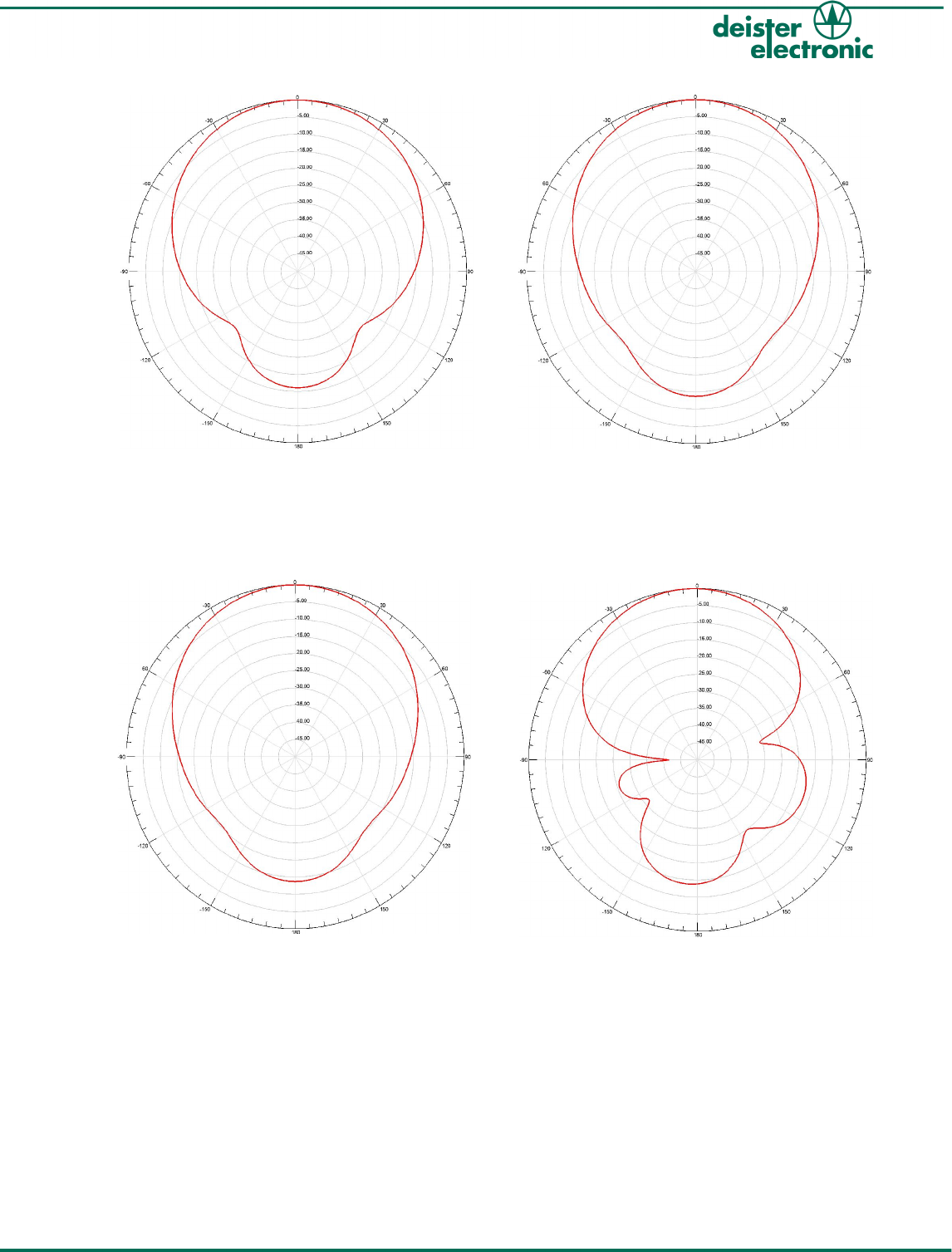
5.4 Radiation Patterns of the Transmitting Antenna
5.4.1 Cutting Plane Diagram
The following diagram shows a perspective view of the TSU25DB in order to help
assigning the following cutting planes to the orientation of the reader within space.
8ts_tsu25db_wi_en_v171209_as_bf_de
Wiring and Installation TSU25DB
PRELIMINARY
ts_tsu25db_wi_en_v171209_as_bf_de 9
Wiring and Installation TSU25DB
cutting plane: xz
polarization: vertical
cutting plane: yzxz
polarization: vertical
cutting plane: xz
polarization: horizontal
cutting plane: yz
polarization: horizontal
PRELIMINARY
DB
6. Configuration
Configuration of the device is done in the “tranSpeed Config” software. If the device is
operated via an IDC, configuration is done in the “tranSpeed Commander“ Software.
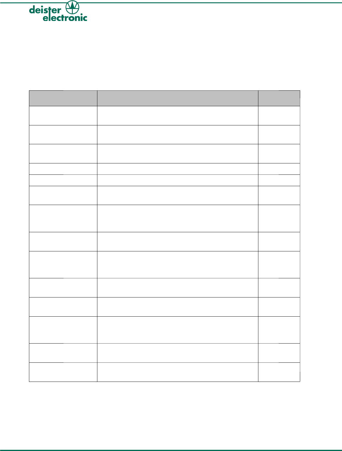
7. Accessories
Article Description Article No.
CC2 Connection cable, grey, 3 m, M12 female connector,
straight, 4-pin
9287.101
CC4 Connection cable, grey, 3 m, M12 female connector,
straight, 4-pin to 4-pin Phoenix connector
9287.301
CC4 Connection cable, grey, 10 m, M12 female connector,
straight, 4-pin to 4-pin Phoenix connector
6236.000
LRM1 Ball joint bracket 6103.000
LRM3 Base plate for mast mounting 6106.000
AC/DC power supply
Euro
Power supply for expansion module, input voltage 230
VAC, output voltage 12 VDC (1 A), Friwo® plug
8812.000
AC/DC
power supply
International
Power supply, input voltage 100-230 VAC, incl. adapter
for USA/Japan and United Kingdom, output voltage 12
VDC (1.25 A), Friwo® plug
6757.000
AC/DC Power Supply Power supply for c-rail mounting, input voltage 90-260
VAC, 50-60 Hz output voltage 24 VDC (2.5 A)
6756.000
SNG3
Smart Network
Gateway
Interface converter USB-to-RS485, incl. USB interface
cable, power supply with standard deister power supply
12 VDC, Friwo® plug
8782.000
DBC deBus Converter, Interface converter for deBus
components, power supply 10-30 VDC
6232.000
IDC Controller for the connection to deBus-readers
power supply 10-30 VDC
6230.000
SIC1 Serial Interface Converter from RS485/deBus protocol to
Open Collector/Wiegand, Dataclock, Magstripe
protocol, power supply 10-30 VDC
6233.000
SIC2 Serial Interface Converter from RS485/deBus protocol to
RS485/customized protocol, power supply 10-30 VDC
6234.000
SIC3 Serial Interface Converter from RS485/deBus protocol to
RS232, power supply 10-30 VDC
6235.000
Table 1: Accessories for TSU25DB
10 ts_tsu25db_wi_en_v171209_as_bf_de
Wiring and Installation TSU25DB
PRELIMINARY

Notes:
ts_tsu25db_wi_en_v171209_as_bf_de 11
Wiring and Installation TSU25DB
PRELIMINARY

Germany:
deister electronic GmbH
Hermann-Bahlsen Str. 11
30890 Barsinghausen
Tel.: +49 (0) 51 05 - 51 61 11
Fax: +49 (0) 51 05 - 51 62 17
info.de@deister.com
www.deister.com
deister worldwide
Canada:
Deister Electronics Inc.
4-1550 Kingston Road,
Suite 1411
Pickering, Ontario,
Canada L1V6W9
Tel.: +1 905 - 837 5666
Fax: +1 905 - 837 0777
info.ca@deister.com
Japan:
deister electronic Japan, LTD.
Toshiba Hoshikawa Bldg. 4F
2-4 Kawabe-chô
Hodogaya-ku, Yokohama-shi
Kanagawa, 240-0001
Tel.: +81 (0) 45 340 1831
Fax: +81 (0) 45 340 1801
info.jp@deister.com
USA:
Deister Electronics USA, Inc.
9303 Grant Avenue
Manassas, VA 20110
Tel.: +1 703 - 368 2739
Fax: +1 703 - 368 9791
info.us@deister.com
Benelux:
deister electronic office
Business Park E 19
Battelsesteenweg 455/A
2800 Mechelen
Tel.: +32 (0) 15 - 28 09 68
Fax: +32 (0) 15 - 28 09 71
info.be@deister.com
France:
deister electronic france
101 rue Pierre Semard
92320 Chatillon
Tel.: +33 (0) 1 47 - 35 78 78
Fax: +33 (0) 1 47 - 35 92 59
info.fr@deister.com
Great Britain:
deister electronic (UK) Ltd.
Stapleton Way, Enterprise Park
Spalding, Lincolnshire
PE11 3YQ
Tel.: +44 (0) 1775 - 717100
Fax: +44 (0) 1775 - 717101
info.uk@deister.com
The Netherlands:
deister electronic office
Tolnasingel 3
2411 PV Bodegraven
Tel.: +31 (0) 1726 - 32970
Fax: +31 (0) 1726 - 32971
info.nl@deister.com
PRELIMINARY