Dell Networking N2000 Series Users Manual User's Guide
2015-01-05
: Dell Dell-Dell-Networking-N2000-Series-Users-Manual-136323 dell-dell-networking-n2000-series-users-manual-136323 dell pdf
Open the PDF directly: View PDF ![]() .
.
Page Count: 1460 [warning: Documents this large are best viewed by clicking the View PDF Link!]
- Introduction
- Switch Feature Overview
- System Management Features
- Multiple Management Options
- System Time Management
- Log Messages
- Integrated DHCP Server
- Management of Basic Network Information
- IPv6 Management Features
- Dual Software Images
- File Management
- Switch Database Management Templates
- Automatic Installation of Firmware and Configuration
- sFlow
- SNMP Alarms and Trap Logs
- CDP Interoperability through ISDP
- Remote Monitoring (RMON)
- Stacking Features
- High Stack Count
- Single IP Management
- Master Failover with Transparent Transition
- Nonstop Forwarding on the Stack
- Hot Add/Delete and Firmware Synchronization
- Configurable Access and Authentication Profiles
- Password-Protected Management Access
- Strong Password Enforcement
- TACACS+ Client
- RADIUS Support
- SSH/SSL
- Inbound Telnet Control
- Denial of Service
- Port Protection
- Captive Portal
- Dot1x Authentication (IEEE 802.1X)
- MAC-Based 802.1X Authentication
- Dot1x Monitor Mode
- MAC-Based Port Security
- Access Control Lists (ACL)
- Time-Based ACLs
- IP Source Guard (IPSG)
- DHCP Snooping
- Dynamic ARP Inspection
- Protected Ports (Private VLAN Edge)
- Green Technology Features
- Power over Ethernet (PoE) Plus Features
- Power Over Ethernet (PoE) Plus Configuration
- PoE Plus Support
- Flow Control Support (IEEE 802.3x)
- Head of Line Blocking Prevention
- Alternate Store and Forward (ASF)
- Jumbo Frames Support
- Auto-MDI/MDIX Support
- VLAN-Aware MAC-based Switching
- Back Pressure Support
- Auto Negotiation
- Broadcast Storm Control
- Port Mirroring
- Static and Dynamic MAC Address Tables
- Link Layer Discovery Protocol (LLDP)
- Link Layer Discovery Protocol (LLDP) for Media Endpoint Devices
- Connectivity Fault Management (IEEE 802.1ag)
- Priority-based Flow Control (PFC)
- Data Center Bridging Exchange (DBCx) Protocol
- Enhanced Transmission Selection
- Cisco Protocol Filtering
- DHCP Layer 2 Relay
- VLAN Support
- Port-Based VLANs
- IP Subnet-based VLAN
- MAC-based VLAN
- IEEE 802.1v Protocol-Based VLANs
- GARP and GVRP Support
- Voice VLAN
- Guest VLAN
- Double VLANs
- Spanning Tree Protocol Features
- Routing Features
- Address Resolution Protocol (ARP) Table Management
- VLAN Routing
- IP Configuration
- Open Shortest Path First (OSPF)
- BOOTP/DHCP Relay Agent
- IP Helper and UDP Relay
- Routing Information Protocol
- Router Discovery
- Routing Table
- Virtual Router Redundancy Protocol (VRRP)
- Tunnel and Loopback Interfaces
- IPv6 Configuration
- IPv6 Routes
- OSPFv3
- DHCPv6
- Quality of Service (QoS) Features
- Layer 2 Multicast Features
- MAC Multicast Support
- IGMP Snooping
- IGMP Snooping Querier
- MLD Snooping
- Multicast VLAN Registration
- Distance Vector Multicast Routing Protocol
- Internet Group Management Protocol
- IGMP Proxy
- Protocol Independent Multicast—Dense Mode
- Protocol Independent Multicast—Sparse Mode
- Protocol Independent Multicast—Source Specific Multicast
- Protocol Independent Multicast IPv6 Support
- MLD/MLDv2 (RFC2710/RFC3810)
- System Management Features
- Hardware Overview
- Using Dell OpenManage Switch Administrator
- Using the Command-Line Interface
- Default Settings
- Setting the IP Address and Other Basic Network Information
- Managing QSFP Ports
- Managing a Switch Stack
- Stacking Overview
- Dell Networking N2000, N3000, and N4000 Stacking Compatibility
- How is the Stack Master Selected?
- Adding a Switch to the Stack
- Removing a Switch from the Stack
- How is the Firmware Updated on the Stack?
- What is Stacking Standby?
- What is Nonstop Forwarding?
- Switch Stack MAC Addressing and Stack Design Considerations
- NSF Network Design Considerations
- Why is Stacking Needed?
- Default Stacking Values
- Managing and Monitoring the Stack (Web)
- Managing the Stack (CLI)
- Stacking Overview
- Configuring Authentication, Authorization, and Accounting
- AAA Overview
- Authentication
- Authorization
- Accounting
- Local Authentication Example
- TACACS+ Authentication Example
- Public Key SSH Authentication Example
- RADIUS Authentication Example
- Local Authorization Example—Direct Login to Privileged EXEC Mode
- TACACS+ Authorization Example—Direct Login to Privileged EXEC Mode
- TACACS+ Authorization Example—Administrative Profiles
- TACACS+ Authorization Example—Custom Administrative Profile
- TACACS+ Authorization Example—Per-command Authorization
- RADIUS Authorization Example—Direct Login to Privileged EXEC Mode
- RADIUS Authorization Example—Administrative Profiles
- Using RADIUS Servers to Control Management Access
- Using TACACS+ Servers to Control Management Access
- Default Configurations
- Monitoring and Logging System Information
- System Monitoring Overview
- Monitoring System Information and Configuring Logging (Web)
- Device Information
- System Health
- System Resources
- Unit Power Usage History
- Integrated Cable Test for Copper Cables
- Optical Transceiver Diagnostics
- Log Global Settings
- RAM Log
- Log File
- Syslog Server
- Email Alert Global Configuration
- Email Alert Mail Server Configuration
- Email Alert Subject Configuration
- Email Alert To Address Configuration
- Email Alert Statistics
- Monitoring System Information and Configuring Logging (CLI)
- Logging Configuration Examples
- Managing General System Settings
- System Settings Overview
- Default General System Information
- Configuring General System Settings (Web)
- System Information
- CLI Banner
- SDM Template Preference
- Clock
- SNTP Global Settings
- SNTP Authentication
- SNTP Server
- Summer Time Configuration
- Time Zone Configuration
- Card Configuration
- Slot Summary
- Supported Cards
- Power Over Ethernet Global Configuration (N2024P/N2048P and N3024P/N3048P Only)
- Power Over Ethernet Interface Configuration (N2024P/N2048P and N3024P/N3048P Only)
- Configuring System Settings (CLI)
- Configuring System Information
- Configuring the Banner
- Managing the SDM Template
- Configuring SNTP Authentication and an SNTP Server
- Setting the System Time and Date Manually
- Configuring the Expansion Slots (N3000 Series Only)
- Viewing Slot Information (N4000 Series Only)
- Configuring PoE Settings (N2024P/N2048P and N3024P/N3048P Only)
- General System Settings Configuration Examples
- Configuring SNMP
- Managing Images and Files
- Automatically Updating the Image and Configuration
- Auto Configuration Overview
- What Is USB Auto Configuration?
- What Files Does USB Auto Configuration Use?
- How Does USB Auto Configuration Use the Files on the USB Device?
- What Is the Setup File Format?
- What Is the DHCP Auto Configuration Process?
- Monitoring and Completing the DHCP Auto Configuration Process
- What Are the Dependencies for DHCP Auto Configuration?
- Default Auto Configuration Values
- Managing Auto Configuration (Web)
- Managing Auto Configuration (CLI)
- Auto Configuration Example
- Auto Configuration Overview
- Monitoring Switch Traffic
- Traffic Monitoring Overview
- Default Traffic Monitoring Values
- Monitoring Switch Traffic (Web)
- sFlow Agent Summary
- sFlow Receiver Configuration
- sFlow Sampler Configuration
- sFlow Poll Configuration
- Interface Statistics
- Etherlike Statistics
- GVRP Statistics
- EAP Statistics
- Utilization Summary
- Counter Summary
- Switchport Statistics
- RMON Statistics
- RMON History Control Statistics
- RMON History Table
- RMON Event Control
- RMON Event Log
- RMON Alarms
- Port Statistics
- LAG Statistics
- Port Mirroring
- Monitoring Switch Traffic (CLI)
- Traffic Monitoring Configuration Examples
- Configuring iSCSI Optimization
- iSCSI Optimization Overview
- What Does iSCSI Optimization Do?
- How Does the Switch Detect iSCSI Traffic Flows?
- How Is Quality of Service Applied to iSCSI Traffic Flows?
- How Does iSCSI Optimization Use ACLs?
- What Information Does the Switch Track in iSCSI Traffic Flows?
- How Does iSCSI Optimization Interact With Dell EqualLogic Arrays?
- What Occurs When iSCSI Optimization Is Enabled or Disabled?
- How Does iSCSI Optimization Interact with DCBx?
- How Does iSCSI Optimization Interact with Dell Compellent Arrays?
- iSCSI CoS and Priority Flow Control/Enhanced Transmission Selection Interactions
- Default iSCSI Optimization Values
- Configuring iSCSI Optimization (Web)
- Configuring iSCSI Optimization (CLI)
- iSCSI Optimization Configuration Examples
- iSCSI Optimization Overview
- Configuring Port Characteristics
- Configuring Port and System Security
- Configuring Access Control Lists
- Configuring VLANs
- VLAN Overview
- Default VLAN Behavior
- Configuring VLANs (Web)
- Configuring VLANs (CLI)
- Creating a VLAN
- Configuring a Port in Access Mode
- Configuring a Port in Trunk Mode
- Configuring a Port in General Mode
- Configuring VLAN Settings for a LAG
- Configuring Double VLAN Tagging
- Configuring MAC-Based VLANs
- Configuring IP-Based VLANs
- Configuring a Protocol-Based VLAN
- Configuring GVRP
- Configuring Voice VLANs
- VLAN Configuration Examples
- Configuring the Spanning Tree Protocol
- Discovering Network Devices
- Configuring Port-Based Traffic Control
- Configuring L2 Multicast Features
- L2 Multicast Overview
- Snooping Switch Restrictions
- Default L2 Multicast Values
- Configuring L2 Multicast Features (Web)
- Multicast Global Parameters
- Bridge Multicast Group
- MRouter Status
- General IGMP Snooping
- Global Querier Configuration
- VLAN Querier
- VLAN Querier Status
- MFDB IGMP Snooping Table
- MLD Snooping General
- MLD Snooping Global Querier Configuration
- MLD Snooping VLAN Querier
- MLD Snooping VLAN Querier Status
- MFDB MLD Snooping Table
- MVR Global Configuration
- MVR Members
- MVR Interface Configuration
- MVR Statistics
- GARP Timers
- GMRP Parameters
- MFDB GMRP Table
- Configuring L2 Multicast Features (CLI)
- Case Study on a Real-World Network Topology
- Configuring Connectivity Fault Management
- Snooping and Inspecting Traffic
- Traffic Snooping and Inspection Overview
- Default Traffic Snooping and Inspection Values
- Configuring Traffic Snooping and Inspection (Web)
- DHCP Snooping Configuration
- DHCP Snooping Interface Configuration
- DHCP Snooping VLAN Configuration
- DHCP Snooping Persistent Configuration
- DHCP Snooping Static Bindings Configuration
- DHCP Snooping Dynamic Bindings Summary
- DHCP Snooping Statistics
- IPSG Interface Configuration
- IPSG Binding Configuration
- IPSG Binding Summary
- DAI Global Configuration
- DAI Interface Configuration
- DAI VLAN Configuration
- DAI ACL Configuration
- DAI ACL Rule Configuration
- DAI Statistics
- Configuring Traffic Snooping and Inspection (CLI)
- Traffic Snooping and Inspection Configuration Examples
- Configuring Link Aggregation
- Configuring Data Center Bridging Features
- Managing the MAC Address Table
- Configuring Routing Interfaces
- Configuring DHCP Server and Relay Settings
- Configuring IP Routing
- Configuring L2 and L3 Relay Features
- Configuring OSPF and OSPFv3
- OSPF Overview
- OSPF Feature Details
- Default OSPF Values
- Configuring OSPF Features (Web)
- OSPF Configuration
- OSPF Area Configuration
- OSPF Stub Area Summary
- OSPF Area Range Configuration
- OSPF Interface Statistics
- OSPF Interface Configuration
- OSPF Neighbor Table
- OSPF Neighbor Configuration
- OSPF Link State Database
- OSPF Virtual Link Configuration
- OSPF Virtual Link Summary
- OSPF Route Redistribution Configuration
- OSPF Route Redistribution Summary
- NSF OSPF Configuration
- Configuring OSPFv3 Features (Web)
- OSPFv3 Configuration
- OSPFv3 Area Configuration
- OSPFv3 Stub Area Summary
- OSPFv3 Area Range Configuration
- OSPFv3 Interface Configuration
- OSPFv3 Interface Statistics
- OSPFv3 Neighbors
- OSPFv3 Neighbor Table
- OSPFv3 Link State Database
- OSPFv3 Virtual Link Configuration
- OSPFv3 Virtual Link Summary
- OSPFv3 Route Redistribution Configuration
- OSPFv3 Route Redistribution Summary
- NSF OSPFv3 Configuration
- Configuring OSPF Features (CLI)
- Configuring OSPFv3 Features (CLI)
- OSPF Configuration Examples
- Configuring RIP
- Configuring VRRP
- Configuring IPv6 Routing
- Configuring DHCPv6 Server and Relay Settings
- Configuring Differentiated Services
- Configuring Class-of-Service
- Configuring Auto VoIP
- Managing IPv4 and IPv6 Multicast
- L3 Multicast Overview
- Default L3 Multicast Values
- Configuring General IPv4 Multicast Features (Web)
- Configuring IPv6 Multicast Features (Web)
- Configuring IGMP and IGMP Proxy (Web)
- Configuring MLD and MLD Proxy (Web)
- MLD Global Configuration
- MLD Routing Interface Configuration
- MLD Routing Interface Summary
- MLD Routing Interface Cache Information
- MLD Routing Interface Source List Information
- MLD Traffic
- MLD Proxy Configuration
- MLD Proxy Configuration Summary
- MLD Proxy Interface Membership Information
- Detailed MLD Proxy Interface Membership Information
- Configuring PIM for IPv4 and IPv6 (Web)
- Configuring DVMRP (Web)
- Configuring L3 Multicast Features (CLI)
- Configuring and Viewing IPv4 Multicast Information
- Configuring and Viewing IPv6 Multicast Route Information
- Configuring and Viewing IGMP
- Configuring and Viewing IGMP Proxy
- Configuring and Viewing MLD
- Configuring and Viewing MLD Proxy
- Configuring and Viewing PIM-DM for IPv4 Multicast Routing
- Configuring and Viewing PIM-DM for IPv6 Multicast Routing
- Configuring and Viewing PIM-SM for IPv4 Multicast Routing
- Configuring and Viewing PIM-SM for IPv6 Multicast Routing
- Configuring and Viewing DVMRP Information
- L3 Multicast Configuration Examples
- Feature Limitations and Platform Constants
- System Process Definitions
- Index

Dell Networking
N2000, N3000, and N4000
Series Switches
User’s Configuration
Guide
Regulatory Models: N2024, N2024P,
N2038,N2048P, N3024, N3024F, N3024P,
N3048, N3048P, N4032, N4032F, N4064,
N4064F

Notes and Cautions
NOTE: A NOTE indicates important information that helps you make better use of
your computer.
CAUTION: A CAUTION indicates potential damage to hardware or loss of data if
instructions are not followed.
____________
Information in this publication is subject to change without notice.
© 2014 Dell Inc. All rights reserved.
Reproduction of these materials in any manner whatsoever without the written permission of Dell Inc.
is strictly forbidden.
Trademarks used in this text: Dell™, the DELL logo, EqualLogic™, and OpenManage™ are
trademarks of Dell Inc. Microsoft®, Windows®, Windows Server®, MS-DOS®, and Windows Vista®
are either trademarks or registered trademarks of Microsoft Corporation in the United States and/or
other countries. sFlow® is a registered trademark of InMon Corporation. Cisco® is a registered
trademark of Cisco Systems. Mozilla® and Firefox® are registered trademarks of the Mozilla
Foundation.
Other trademarks and trade names may be used in this publication to refer to either the entities claiming
the marks and names or their products. Dell Inc. disclaims any proprietary interest in trademarks and
trade names other than its own.
Regulatory Models: N2024, N2024P, N2038,N2048P, N3024, N3024F, N3024P, N3048, N3048P, N4032, N4032F, N4064, N4064F
January 2014 Rev. A01

Contents 3
Contents
1 Introduction . . . . . . . . . . . . . . . . . . . . . . . 51
About This Document . . . . . . . . . . . . . . . . . . 51
Audience . . . . . . . . . . . . . . . . . . . . . . . . . 52
Document Conventions . . . . . . . . . . . . . . . . . 52
Additional Documentation. . . . . . . . . . . . . . . . 53
2 Switch Feature Overview . . . . . . . . . . . . 55
System Management Features . . . . . . . . . . . . . 56
Multiple Management Options . . . . . . . . . . . 56
System Time Management . . . . . . . . . . . . . 56
Log Messages . . . . . . . . . . . . . . . . . . . 57
Integrated DHCP Server . . . . . . . . . . . . . . 57
Management of Basic Network Information. . . . 57
IPv6 Management Features . . . . . . . . . . . . 58
Dual Software Images . . . . . . . . . . . . . . . 58
File Management . . . . . . . . . . . . . . . . . . 58
Switch Database Management Templates. . . . . 58
Automatic Installation of Firmware and
Configuration . . . . . . . . . . . . . . . . . . . . 59
sFlow . . . . . . . . . . . . . . . . . . . . . . . . 59
SNMP Alarms and Trap Logs . . . . . . . . . . . . 60
CDP Interoperability through ISDP . . . . . . . . . 60
Remote Monitoring (RMON) . . . . . . . . . . . . 60
Stacking Features . . . . . . . . . . . . . . . . . . . . 61
High Stack Count . . . . . . . . . . . . . . . . . . 61

4Contents
Single IP Management . . . . . . . . . . . . . . . 61
Master Failover with Transparent Transition . . . . 62
Nonstop Forwarding on the Stack . . . . . . . . . 62
Hot Add/Delete and Firmware
Synchronization . . . . . . . . . . . . . . . . . . . 62
Security Features . . . . . . . . . . . . . . . . . . . . 63
Configurable Access and Authentication
Profiles . . . . . . . . . . . . . . . . . . . . . . . 63
Password-Protected Management Access . . . . 63
Strong Password Enforcement . . . . . . . . . . . 63
TACACS+ Client . . . . . . . . . . . . . . . . . . . 63
RADIUS Support . . . . . . . . . . . . . . . . . . 64
SSH/SSL. . . . . . . . . . . . . . . . . . . . . . . 64
Inbound Telnet Control . . . . . . . . . . . . . . . 64
Denial of Service . . . . . . . . . . . . . . . . . . 64
Port Protection . . . . . . . . . . . . . . . . . . . 64
Captive Portal . . . . . . . . . . . . . . . . . . . . 65
Dot1x Authentication (IEEE 802.1X) . . . . . . . . . 66
MAC-Based 802.1X Authentication . . . . . . . . . 66
Dot1x Monitor Mode . . . . . . . . . . . . . . . . 66
MAC-Based Port Security . . . . . . . . . . . . . 66
Access Control Lists (ACL) . . . . . . . . . . . . . 67
Time-Based ACLs . . . . . . . . . . . . . . . . . . 67
IP Source Guard (IPSG). . . . . . . . . . . . . . . 67
DHCP Snooping . . . . . . . . . . . . . . . . . . . 68
Dynamic ARP Inspection . . . . . . . . . . . . . . 68
Protected Ports (Private VLAN Edge). . . . . . . . 68
Green Technology Features . . . . . . . . . . . . . . . 69
Energy Detect Mode . . . . . . . . . . . . . . . . 69
Energy Efficient Ethernet . . . . . . . . . . . . . . 69
Power Utilization Reporting. . . . . . . . . . . . . 69

Contents 5
Power over Ethernet (PoE) Plus Features . . . . . . . . 70
Power Over Ethernet (PoE) Plus
Configuration . . . . . . . . . . . . . . . . . . . . 70
PoE Plus Support . . . . . . . . . . . . . . . . . . 70
Switching Features . . . . . . . . . . . . . . . . . . . 71
Flow Control Support (IEEE 802.3x) . . . . . . . . . 71
Head of Line Blocking Prevention . . . . . . . . . 71
Alternate Store and Forward (ASF). . . . . . . . . 71
Jumbo Frames Support . . . . . . . . . . . . . . . 71
Auto-MDI/MDIX Support . . . . . . . . . . . . . . 72
VLAN-Aware MAC-based Switching. . . . . . . . 72
Back Pressure Support . . . . . . . . . . . . . . . 72
Auto Negotiation . . . . . . . . . . . . . . . . . . 72
Broadcast Storm Control . . . . . . . . . . . . . . 73
Port Mirroring. . . . . . . . . . . . . . . . . . . . 73
Static and Dynamic MAC Address Tables . . . . . 73
Link Layer Discovery Protocol (LLDP) . . . . . . . 74
Link Layer Discovery Protocol (LLDP) for
Media Endpoint Devices . . . . . . . . . . . . . . 74
Connectivity Fault Management
(IEEE 802.1ag) . . . . . . . . . . . . . . . . . . . . 74
Priority-based Flow Control (PFC) . . . . . . . . . 74
Data Center Bridging Exchange (DBCx)
Protocol . . . . . . . . . . . . . . . . . . . . . . . 75
Enhanced Transmission Selection . . . . . . . . . 75
Cisco Protocol Filtering. . . . . . . . . . . . . . . 76
DHCP Layer 2 Relay. . . . . . . . . . . . . . . . . 76
Virtual Local Area Network Supported Features . . . . 77
VLAN Support. . . . . . . . . . . . . . . . . . . . 77
Port-Based VLANs . . . . . . . . . . . . . . . . . 77
IP Subnet-based VLAN . . . . . . . . . . . . . . . 77
MAC-based VLAN . . . . . . . . . . . . . . . . . 77
IEEE 802.1v Protocol-Based VLANs . . . . . . . . 77

6Contents
GARP and GVRP Support . . . . . . . . . . . . . . 78
Voice VLAN . . . . . . . . . . . . . . . . . . . . . 78
Guest VLAN . . . . . . . . . . . . . . . . . . . . . 78
Double VLANs. . . . . . . . . . . . . . . . . . . . 78
Spanning Tree Protocol Features . . . . . . . . . . . . 79
Spanning Tree Protocol (STP) . . . . . . . . . . . 79
Spanning Tree Port Settings . . . . . . . . . . . . 79
Rapid Spanning Tree . . . . . . . . . . . . . . . . 79
Multiple Spanning Tree . . . . . . . . . . . . . . . 79
Bridge Protocol Data Unit (BPDU) Guard. . . . . . 80
BPDU Filtering . . . . . . . . . . . . . . . . . . . 80
RSTP-PV and STP-PV . . . . . . . . . . . . . . . . 80
Link Aggregation Features. . . . . . . . . . . . . . . . 81
Link Aggregation . . . . . . . . . . . . . . . . . . 81
Link Aggregate Control Protocol (LACP) . . . . . . 81
Multi-Switch LAG (MLAG) . . . . . . . . . . . . . 81
Routing Features . . . . . . . . . . . . . . . . . . . . . 82
Address Resolution Protocol (ARP) Table
Management . . . . . . . . . . . . . . . . . . . . 82
VLAN Routing . . . . . . . . . . . . . . . . . . . . 82
IP Configuration . . . . . . . . . . . . . . . . . . . 82
Open Shortest Path First (OSPF) . . . . . . . . . . 82
BOOTP/DHCP Relay Agent . . . . . . . . . . . . . 83
IP Helper and UDP Relay . . . . . . . . . . . . . . 83
Routing Information Protocol . . . . . . . . . . . . 83
Router Discovery . . . . . . . . . . . . . . . . . . 83
Routing Table . . . . . . . . . . . . . . . . . . . . 83
Virtual Router Redundancy Protocol (VRRP) . . . . 84
Tunnel and Loopback Interfaces . . . . . . . . . . 84
IPv6 Routing Features . . . . . . . . . . . . . . . . . . 85
IPv6 Configuration . . . . . . . . . . . . . . . . . 85

Contents 7
IPv6 Routes . . . . . . . . . . . . . . . . . . . . . 85
OSPFv3 . . . . . . . . . . . . . . . . . . . . . . . 85
DHCPv6 . . . . . . . . . . . . . . . . . . . . . . . 85
Quality of Service (QoS) Features . . . . . . . . . . . . 86
Differentiated Services (DiffServ) . . . . . . . . . 86
Class Of Service (CoS) . . . . . . . . . . . . . . . 86
Auto Voice over IP (VoIP). . . . . . . . . . . . . . 86
Internet Small Computer System Interface
(iSCSI) Optimization. . . . . . . . . . . . . . . . . 87
Layer 2 Multicast Features . . . . . . . . . . . . . . . 87
MAC Multicast Support. . . . . . . . . . . . . . . 87
IGMP Snooping . . . . . . . . . . . . . . . . . . . 87
IGMP Snooping Querier . . . . . . . . . . . . . . 88
MLD Snooping . . . . . . . . . . . . . . . . . . . 88
Multicast VLAN Registration . . . . . . . . . . . . 88
Layer 3 Multicast Features . . . . . . . . . . . . . . . 89
Distance Vector Multicast Routing Protocol . . . . 89
Internet Group Management Protocol . . . . . . . 89
IGMP Proxy . . . . . . . . . . . . . . . . . . . . . 89
Protocol Independent Multicast—
Dense Mode . . . . . . . . . . . . . . . . . . . . 89
Protocol Independent Multicast—
Sparse Mode . . . . . . . . . . . . . . . . . . . . 90
Protocol Independent Multicast—
Source Specific Multicast . . . . . . . . . . . . . 90
Protocol Independent Multicast IPv6 Support . . . 90
MLD/MLDv2 (RFC2710/RFC3810) . . . . . . . . . . 90
3 Hardware Overview. . . . . . . . . . . . . . . . . 91
Dell Networking N2000 Series Switch Hardware . . . 91
N2000 Series Front Panel . . . . . . . . . . . . . . 91

8Contents
N2000 Series Back Panel . . . . . . . . . . . . . . 95
N2000 LED Definitions. . . . . . . . . . . . . . . . 97
Power Consumption for N2000 Series PoE
Switches . . . . . . . . . . . . . . . . . . . . . 100
Dell Networking N3000 Series Switch
Hardware. . . . . . . . . . . . . . . . . . . . . . . . 102
N3000 Series Front Panel . . . . . . . . . . . . . 102
N3000 Series Back Panel . . . . . . . . . . . . . 106
LED Definitions . . . . . . . . . . . . . . . . . . 109
Power Consumption for N3000 Series PoE
Switches . . . . . . . . . . . . . . . . . . . . . 113
Dell Networking N4000 Series Switch
Hardware. . . . . . . . . . . . . . . . . . . . . . . . 115
Front Panel . . . . . . . . . . . . . . . . . . . . 115
N4000 Back Panel. . . . . . . . . . . . . . . . . 119
LED Definitions . . . . . . . . . . . . . . . . . . 121
Switch MAC Addresses . . . . . . . . . . . . . . . . 125
4 Using Dell OpenManage Switch
Administrator . . . . . . . . . . . . . . . . . . . . 127
About Dell OpenManage Switch Administrator. . . . 127
Starting the Application . . . . . . . . . . . . . . . . 128
Understanding the Interface . . . . . . . . . . . . . . 129
Using the Switch Administrator Buttons and
Links . . . . . . . . . . . . . . . . . . . . . . . . . . 131
Defining Fields . . . . . . . . . . . . . . . . . . . . . 132
Understanding the Device View . . . . . . . . . . . . 132
Using the Device View Port Features. . . . . . . 132

Contents 9
Using the Device View Switch Locator
Feature . . . . . . . . . . . . . . . . . . . . . . . 133
5 Using the Command-Line Interface. . . . 135
Accessing the Switch Through the CLI . . . . . . . . . 135
Console Connection . . . . . . . . . . . . . . . . 135
Telnet Connection . . . . . . . . . . . . . . . . . 136
Understanding Command Modes . . . . . . . . . . . . 137
Entering CLI Commands . . . . . . . . . . . . . . . . . 139
Using the Question Mark to Get Help . . . . . . . 139
Using Command Completion . . . . . . . . . . . . 140
Entering Abbreviated Commands . . . . . . . . . 140
Negating Commands . . . . . . . . . . . . . . . . 140
Command Output Paging . . . . . . . . . . . . . . 141
Understanding Error Messages . . . . . . . . . . 141
Recalling Commands from the History Buffer . . . 141
. . . . . . . . . . . . . . . . . . . . . . . . . . . 142
6 Default Settings. . . . . . . . . . . . . . . . . . . 143
7 Setting the IP Address and Other
Basic Network Information . . . . . . . . . . 147
IP Address and Network Information Overview . . . . 147
What Is the Basic Network Information? . . . . . 147
Why Is Basic Network Information
Needed? . . . . . . . . . . . . . . . . . . . . . . 148
How Is Basic Network Information
Configured? . . . . . . . . . . . . . . . . . . . . . 149

10 Contents
What Is Out-of-Band Management and
In-Band Management? . . . . . . . . . . . . . . 149
Default Network Information . . . . . . . . . . . . . 151
Configuring Basic Network Information (Web) . . . . 152
Out-of-Band Interface . . . . . . . . . . . . . . 152
IP Interface Configuration (Default VLAN IP
Address). . . . . . . . . . . . . . . . . . . . . . 153
Route Entry Configuration (Switch Default
Gateway) . . . . . . . . . . . . . . . . . . . . . 155
Domain Name Server . . . . . . . . . . . . . . . 157
Default Domain Name . . . . . . . . . . . . . . 158
Host Name Mapping . . . . . . . . . . . . . . . 159
Dynamic Host Name Mapping . . . . . . . . . . 160
Configuring Basic Network Information (CLI). . . . . 161
Enabling the DHCP Client on the OOB Port . . . . 161
Enabling the DHCP Client on the Default
VLAN . . . . . . . . . . . . . . . . . . . . . . . 161
Managing DHCP Leases . . . . . . . . . . . . . 162
Configuring Static Network Information on
the OOB Port . . . . . . . . . . . . . . . . . . . 163
Configuring Static Network Information on
the Default VLAN . . . . . . . . . . . . . . . . . 163
Configuring and Viewing Additional Network
Information . . . . . . . . . . . . . . . . . . . . 164

Contents 11
Basic Network Information Configuration
Example . . . . . . . . . . . . . . . . . . . . . . . . . 166
8 Managing QSFP Ports . . . . . . . . . . . . . . 169
9 Managing a Switch Stack . . . . . . . . . . . 171
Stacking Overview . . . . . . . . . . . . . . . . . . . 171
Dell Networking N2000, N3000, and N4000
Stacking Compatibility . . . . . . . . . . . . . . . 174
How is the Stack Master Selected? . . . . . . . . 175
Adding a Switch to the Stack. . . . . . . . . . . . 176
Removing a Switch from the Stack. . . . . . . . . 177
How is the Firmware Updated on the Stack? . . . 177
What is Stacking Standby? . . . . . . . . . . . . . 178
What is Nonstop Forwarding? . . . . . . . . . . . 178
Switch Stack MAC Addressing and Stack
Design Considerations . . . . . . . . . . . . . . . 181
NSF Network Design Considerations . . . . . . . 181
Why is Stacking Needed? . . . . . . . . . . . . . 182
Default Stacking Values . . . . . . . . . . . . . . . . . 182
Managing and Monitoring the Stack (Web). . . . . . . 184
Unit Configuration . . . . . . . . . . . . . . . . . 184
Stack Summary . . . . . . . . . . . . . . . . . . . 185
Stack Firmware Synchronization . . . . . . . . . . 186
Supported Switches . . . . . . . . . . . . . . . . 187
Stack Port Summary . . . . . . . . . . . . . . . . 188
Stack Port Counters . . . . . . . . . . . . . . . . 189
Stack Port Diagnostics . . . . . . . . . . . . . . . 189
NSF Summary. . . . . . . . . . . . . . . . . . . . 190
Checkpoint Statistics . . . . . . . . . . . . . . . . 191

12 Contents
Managing the Stack (CLI) . . . . . . . . . . . . . . . 192
Configuring Stack Member, Stack Port, and
NSF Settings . . . . . . . . . . . . . . . . . . . 192
Viewing and Clearing Stacking and NSF
Information . . . . . . . . . . . . . . . . . . . . 194
Stacking and NSF Usage Scenarios . . . . . . . . . . 195
Basic Failover . . . . . . . . . . . . . . . . . . . 195
Preconfiguring a Stack Member . . . . . . . . . 197
NSF in the Data Center . . . . . . . . . . . . . . 199
NSF and VoIP . . . . . . . . . . . . . . . . . . . 200
NSF and DHCP Snooping . . . . . . . . . . . . . 201
NSF and the Storage Access Network . . . . . . 202
NSF and Routed Access . . . . . . . . . . . . . 204
10 Configuring Authentication,
Authorization, and Accounting . . . . . . . 207
AAA Overview . . . . . . . . . . . . . . . . . . . . . 207
Methods. . . . . . . . . . . . . . . . . . . . . . 208
Access Lines . . . . . . . . . . . . . . . . . . . 209
Authentication . . . . . . . . . . . . . . . . . . . . . 211
Authentication Types . . . . . . . . . . . . . . . 211
Authorization . . . . . . . . . . . . . . . . . . . . . . 212
Exec Authorization Capabilities. . . . . . . . . . 212
Accounting . . . . . . . . . . . . . . . . . . . . . . . 214
Authentication Examples . . . . . . . . . . . . . . . 215
Local Authentication Example . . . . . . . . . . 215
TACACS+ Authentication Example . . . . . . . . 217
Public Key SSH Authentication Example . . . . . 218
RADIUS Authentication Example . . . . . . . . . 225

Contents 13
Authorization Examples . . . . . . . . . . . . . . . . . 227
Local Authorization Example—Direct
Login to Privileged EXEC Mode. . . . . . . . . . . 227
TACACS+ Authorization Example—Direct
Login to Privileged EXEC Mode. . . . . . . . . . . 227
TACACS+ Authorization Example—
Administrative Profiles . . . . . . . . . . . . . . . 228
TACACS+ Authorization Example—Custom
Administrative Profile. . . . . . . . . . . . . . . . 229
TACACS+ Authorization Example—
Per-command Authorization . . . . . . . . . . . . 230
RADIUS Authorization Example—Direct
Login to Privileged EXEC Mode. . . . . . . . . . . 231
RADIUS Authorization Example—
Administrative Profiles . . . . . . . . . . . . . . . 232
Using RADIUS Servers to Control Management
Access . . . . . . . . . . . . . . . . . . . . . . . . . . 232
How Does RADIUS Control Management
Access?. . . . . . . . . . . . . . . . . . . . . . . 232
Which RADIUS Attributes Does the Switch
Support? . . . . . . . . . . . . . . . . . . . . . . 234
How Are RADIUS Attributes Processed on
the Switch? . . . . . . . . . . . . . . . . . . . . . 236
Using TACACS+ Servers to Control Management
Access . . . . . . . . . . . . . . . . . . . . . . . . . . 237
Which TACACS+ Attributes Does the Switch
Support? . . . . . . . . . . . . . . . . . . . . . . 238
Default Configurations. . . . . . . . . . . . . . . . . . 239
Method Lists . . . . . . . . . . . . . . . . . . . . 239
Access Lines (AAA) . . . . . . . . . . . . . . . . 239
Access Lines (Non-AAA) . . . . . . . . . . . . . . 240
Administrative Profiles . . . . . . . . . . . . . . . 240

14 Contents
11 Monitoring and Logging System
Information . . . . . . . . . . . . . . . . . . . . . . 243
System Monitoring Overview . . . . . . . . . . . . . 243
What System Information Is Monitored? . . . . . 243
Why Is System Information Needed?. . . . . . . 244
Where Are Log Messages Sent? . . . . . . . . . 244
What Are the Severity Levels? . . . . . . . . . . 245
What Are the System Startup and Operation
Logs? . . . . . . . . . . . . . . . . . . . . . . . 245
What Is the Log Message Format? . . . . . . . . 246
What Factors Should Be Considered When
Configuring Logging? . . . . . . . . . . . . . . . 247
Default Log Settings . . . . . . . . . . . . . . . . . . 248
Monitoring System Information and Configuring
Logging (Web) . . . . . . . . . . . . . . . . . . . . . 249
Device Information . . . . . . . . . . . . . . . . 249
System Health. . . . . . . . . . . . . . . . . . . 251
System Resources . . . . . . . . . . . . . . . . 252
Unit Power Usage History . . . . . . . . . . . . 253
Integrated Cable Test for Copper Cables . . . . . 254
Optical Transceiver Diagnostics . . . . . . . . . 255
Log Global Settings . . . . . . . . . . . . . . . . 257
RAM Log . . . . . . . . . . . . . . . . . . . . . 258
Log File . . . . . . . . . . . . . . . . . . . . . . 259
Syslog Server . . . . . . . . . . . . . . . . . . . 259
Email Alert Global Configuration . . . . . . . . . 262
Email Alert Mail Server Configuration . . . . . . 262
Email Alert Subject Configuration . . . . . . . . 264
Email Alert To Address Configuration. . . . . . . 265
Email Alert Statistics . . . . . . . . . . . . . . . 266

Contents 15
Monitoring System Information and Configuring
Logging (CLI) . . . . . . . . . . . . . . . . . . . . . . . 267
Viewing System Information and Enabling
the Locator LED. . . . . . . . . . . . . . . . . . . 267
Running Cable Diagnostics . . . . . . . . . . . . . 268
Configuring Local Logging . . . . . . . . . . . . . 269
Configuring Remote Logging . . . . . . . . . . . . 270
Configuring Mail Server Settings. . . . . . . . . . 271
Configuring Email Alerts for Log Messages . . . . 272
Logging Configuration Examples . . . . . . . . . . . . 274
Configuring Local and Remote Logging . . . . . . 274
Configuring Email Alerting . . . . . . . . . . . . . 276
12 Managing General System Settings . . . 279
System Settings Overview. . . . . . . . . . . . . . . . 279
Why Does System Information Need to
Be Configured? . . . . . . . . . . . . . . . . . . . 281
What Are SDM Templates?. . . . . . . . . . . . . 281
Why is the System Time Needed? . . . . . . . . . 283
How Does SNTP Work? . . . . . . . . . . . . . . 283
What Configuration Is Required for Plug-In
Modules? . . . . . . . . . . . . . . . . . . . . . . 284
What Are the Key PoE Plus Features for the
N2024P/N2048P and N3024P/N3048P
Switches?. . . . . . . . . . . . . . . . . . . . . . 285
Default General System Information . . . . . . . . . . 286
Configuring General System Settings (Web) . . . . 287
System Information . . . . . . . . . . . . . . . . . 287
CLI Banner . . . . . . . . . . . . . . . . . . . . . 290
SDM Template Preference . . . . . . . . . . . . . 291
Clock . . . . . . . . . . . . . . . . . . . . . . . . 292
SNTP Global Settings . . . . . . . . . . . . . . . . 293

16 Contents
SNTP Authentication . . . . . . . . . . . . . . . 294
SNTP Server . . . . . . . . . . . . . . . . . . . 296
Summer Time Configuration . . . . . . . . . . . 299
Time Zone Configuration . . . . . . . . . . . . . 300
Card Configuration . . . . . . . . . . . . . . . . 301
Slot Summary . . . . . . . . . . . . . . . . . . . 302
Supported Cards . . . . . . . . . . . . . . . . . 303
Power Over Ethernet Global Configuration
(N2024P/N2048P and N3024P/N3048P Only) . . . 304
Power Over Ethernet Interface Configuration
(N2024P/N2048P and N3024P/N3048P Only) . . . 305
Configuring System Settings (CLI) . . . . . . . . . . . 307
Configuring System Information . . . . . . . . . 307
Configuring the Banner . . . . . . . . . . . . . . 308
Managing the SDM Template. . . . . . . . . . . 309
Configuring SNTP Authentication and an
SNTP Server . . . . . . . . . . . . . . . . . . . 309
Setting the System Time and Date Manually . . . 311
Configuring the Expansion Slots (N3000
Series Only) . . . . . . . . . . . . . . . . . . . . 312
Viewing Slot Information (N4000 Series
Only). . . . . . . . . . . . . . . . . . . . . . . . 313
Configuring PoE Settings (N2024P/N2048P
and N3024P/N3048P Only) . . . . . . . . . . . . 313
General System Settings Configuration
Examples . . . . . . . . . . . . . . . . . . . . . . . . 315
Configuring System and Banner Information. . . 315
Configuring SNTP . . . . . . . . . . . . . . . . . 319
Configuring the Time Manually . . . . . . . . . . 321
13 Configuring SNMP . . . . . . . . . . . . . . . . . 323
SNMP Overview . . . . . . . . . . . . . . . . . . . . 323
What Is SNMP? . . . . . . . . . . . . . . . . . . 323

Contents 17
What Are SNMP Traps? . . . . . . . . . . . . . . 324
Why Is SNMP Needed? . . . . . . . . . . . . . . 325
Default SNMP Values . . . . . . . . . . . . . . . . . . 325
Configuring SNMP (Web) . . . . . . . . . . . . . . . . 327
SNMP Global Parameters . . . . . . . . . . . . . 327
SNMP View Settings . . . . . . . . . . . . . . . . 328
Access Control Group . . . . . . . . . . . . . . . 330
SNMPv3 User Security Model (USM) . . . . . . . 332
Communities . . . . . . . . . . . . . . . . . . . . 335
Notification Filter . . . . . . . . . . . . . . . . . . 337
Notification Recipients . . . . . . . . . . . . . . . 338
Trap Flags . . . . . . . . . . . . . . . . . . . . . . 340
OSPFv2 Trap Flags . . . . . . . . . . . . . . . . . 341
OSPFv3 Trap Flags . . . . . . . . . . . . . . . . . 342
Trap Log . . . . . . . . . . . . . . . . . . . . . . . 343
Configuring SNMP (CLI) . . . . . . . . . . . . . . . . . 345
Configuring the SNMPv3 Engine ID . . . . . . . . 345
Configuring SNMP Views, Groups, and Users . . . 346
Configuring Communities. . . . . . . . . . . . . . 349
Configuring SNMP Notifications (Traps and
Informs) . . . . . . . . . . . . . . . . . . . . . . . 351
SNMP Configuration Examples . . . . . . . . . . . . . 354
Configuring SNMPv1 and SNMPv2. . . . . . . . . 354
Configuring SNMPv3 . . . . . . . . . . . . . . . . 355
14 Managing Images and Files . . . . . . . . . 359
Image and File Management Overview . . . . . . . . . 359
What Files Can Be Managed? . . . . . . . . . . . 359
Why Is File Management Needed?. . . . . . . . . 361

18 Contents
What Methods Are Supported for File
Management?. . . . . . . . . . . . . . . . . . . 363
What Factors Should Be Considered When
Managing Files?. . . . . . . . . . . . . . . . . . 364
How Is the Running Configuration Saved? . . . . 366
Managing Images and Files (Web) . . . . . . . . . . 367
File System . . . . . . . . . . . . . . . . . . . . 367
Active Images. . . . . . . . . . . . . . . . . . . 368
USB Flash Drive . . . . . . . . . . . . . . . . . . 369
File Download . . . . . . . . . . . . . . . . . . . 370
File Upload . . . . . . . . . . . . . . . . . . . . 372
Copy Files . . . . . . . . . . . . . . . . . . . . . 374
Managing Images and Files (CLI) . . . . . . . . . . . 375
Downloading and Activating a New Image
(TFTP) . . . . . . . . . . . . . . . . . . . . . . . 375
Managing Files in Internal Flash . . . . . . . . . 377
Managing Files on a USB Flash Device . . . . . 379
Uploading a Configuration File (SCP) . . . . . . . 379
Managing Configuration Scripts (SFTP) . . . . . 380
File and Image Management Configuration
Examples . . . . . . . . . . . . . . . . . . . . . . . . 381
Upgrading the Firmware . . . . . . . . . . . . . 381
Managing Configuration Scripts . . . . . . . . . 384
Managing Files by Using the USB Flash
Drive. . . . . . . . . . . . . . . . . . . . . . . . 386
15 Automatically Updating the Image
and Configuration . . . . . . . . . . . . . . . . . 389
Auto Configuration Overview . . . . . . . . . . . . . 389
What Is USB Auto Configuration? . . . . . . . . 390
What Files Does USB Auto Configuration
Use? . . . . . . . . . . . . . . . . . . . . . . . . 390

Contents 19
How Does USB Auto Configuration Use the
Files on the USB Device?. . . . . . . . . . . . . . 391
What Is the Setup File Format?. . . . . . . . . . . 392
What Is the DHCP Auto Configuration
Process? . . . . . . . . . . . . . . . . . . . . . . 393
Monitoring and Completing the DHCP Auto
Configuration Process . . . . . . . . . . . . . . . 398
What Are the Dependencies for DHCP Auto
Configuration? . . . . . . . . . . . . . . . . . . . 399
Default Auto Configuration Values . . . . . . . . . . . 400
Managing Auto Configuration (Web) . . . . . . . . . . 401
Auto-Install Configuration . . . . . . . . . . . . . 401
Managing Auto Configuration (CLI) . . . . . . . . . . . 402
Managing Auto Configuration . . . . . . . . . . . 402
Auto Configuration Example. . . . . . . . . . . . . . . 403
Enabling USB Auto Configuration and Auto
Image Download . . . . . . . . . . . . . . . . . . 403
Enabling DHCP Auto Configuration and Auto
Image Download . . . . . . . . . . . . . . . . . . 405
Easy Image Upgrade via USB . . . . . . . . . . . 406
16 Monitoring Switch Traffic . . . . . . . . . . . 407
Traffic Monitoring Overview . . . . . . . . . . . . . . 407
What is sFlow Technology?. . . . . . . . . . . . . 407
What is RMON?. . . . . . . . . . . . . . . . . . . 410
What is Port Mirroring?. . . . . . . . . . . . . . . 411
Port Mirroring Behaviors . . . . . . . . . . . . . . 412
Remote Capture. . . . . . . . . . . . . . . . . . . 413
Why is Traffic Monitoring Needed? . . . . . . . . 413

20 Contents
Default Traffic Monitoring Values . . . . . . . . . . . 414
Monitoring Switch Traffic (Web) . . . . . . . . . . . 414
sFlow Agent Summary . . . . . . . . . . . . . . 414
sFlow Receiver Configuration . . . . . . . . . . 416
sFlow Sampler Configuration . . . . . . . . . . . 417
sFlow Poll Configuration . . . . . . . . . . . . . 418
Interface Statistics . . . . . . . . . . . . . . . . 419
Etherlike Statistics . . . . . . . . . . . . . . . . 420
GVRP Statistics . . . . . . . . . . . . . . . . . . 421
EAP Statistics . . . . . . . . . . . . . . . . . . . 422
Utilization Summary. . . . . . . . . . . . . . . . 423
Counter Summary. . . . . . . . . . . . . . . . . 424
Switchport Statistics . . . . . . . . . . . . . . . 425
RMON Statistics . . . . . . . . . . . . . . . . . 426
RMON History Control Statistics . . . . . . . . . 427
RMON History Table . . . . . . . . . . . . . . . 429
RMON Event Control . . . . . . . . . . . . . . . 430
RMON Event Log . . . . . . . . . . . . . . . . . 432
RMON Alarms. . . . . . . . . . . . . . . . . . . 433
Port Statistics . . . . . . . . . . . . . . . . . . . 435
LAG Statistics . . . . . . . . . . . . . . . . . . . 436
Port Mirroring . . . . . . . . . . . . . . . . . . . 437
Monitoring Switch Traffic (CLI) . . . . . . . . . . . . 439
Configuring sFlow . . . . . . . . . . . . . . . . . 439
Configuring RMON . . . . . . . . . . . . . . . . 441
Viewing Statistics . . . . . . . . . . . . . . . . . 443
Configuring Port Mirroring . . . . . . . . . . . . 444
Configuring RSPAN . . . . . . . . . . . . . . . . 445
Traffic Monitoring Configuration Examples . . . . . . 447
Configuring sFlow . . . . . . . . . . . . . . . . . 447
Configuring RMON . . . . . . . . . . . . . . . . 449
Configuring Remote Capture . . . . . . . . . . . 450
Configuring RSPAN . . . . . . . . . . . . . . . . 455

Contents 21
17 Configuring iSCSI Optimization . . . . . . . 459
iSCSI Optimization Overview . . . . . . . . . . . . . . 459
What Does iSCSI Optimization Do?. . . . . . . . . 460
How Does the Switch Detect iSCSI
Traffic Flows? . . . . . . . . . . . . . . . . . . . . 460
How Is Quality of Service Applied to iSCSI
Traffic Flows? . . . . . . . . . . . . . . . . . . . . 460
How Does iSCSI Optimization Use ACLs? . . . . . 461
What Information Does the Switch Track in
iSCSI Traffic Flows?. . . . . . . . . . . . . . . . . 462
How Does iSCSI Optimization Interact With
Dell EqualLogic Arrays? . . . . . . . . . . . . . . 463
What Occurs When iSCSI Optimization Is
Enabled or Disabled? . . . . . . . . . . . . . . . . 463
How Does iSCSI Optimization Interact with
DCBx?. . . . . . . . . . . . . . . . . . . . . . . . 464
How Does iSCSI Optimization Interact with
Dell Compellent Arrays? . . . . . . . . . . . . . . 464
iSCSI CoS and Priority Flow Control/Enhanced
Transmission Selection Interactions . . . . . . . . 465
Default iSCSI Optimization Values . . . . . . . . . . . 466
Configuring iSCSI Optimization (Web) . . . . . . . . . 467
iSCSI Global Configuration . . . . . . . . . . . . . 467
iSCSI Targets Table . . . . . . . . . . . . . . . . . 468
iSCSI Sessions Table . . . . . . . . . . . . . . . . 469
iSCSI Sessions Detailed . . . . . . . . . . . . . . 470
Configuring iSCSI Optimization (CLI) . . . . . . . . . . 471
iSCSI Optimization Configuration Examples . . . . . . 473
Configuring iSCSI Optimization Between
Servers and a Disk Array . . . . . . . . . . . . . . 473

22 Contents
18 Configuring Port Characteristics. . . . . . 477
Port Overview . . . . . . . . . . . . . . . . . . . . . 477
What Physical Port Characteristics Can
Be Configured? . . . . . . . . . . . . . . . . . . 477
What is Link Dependency? . . . . . . . . . . . . 479
What Interface Types are Supported? . . . . . . 481
What is Interface Configuration Mode? . . . . . 481
What Are the Green Ethernet Features? . . . . . 483
Default Port Values. . . . . . . . . . . . . . . . . . . 485
Configuring Port Characteristics (Web) . . . . . . . . 486
Port Configuration. . . . . . . . . . . . . . . . . 486
Link Dependency Configuration . . . . . . . . . 489
Link Dependency Summary. . . . . . . . . . . . 491
Port Green Ethernet Configuration . . . . . . . . 492
Port Green Ethernet Statistics . . . . . . . . . . 493
Port Green Ethernet LPI History . . . . . . . . . 495
Configuring Port Characteristics (CLI). . . . . . . . . 496
Configuring Port Settings . . . . . . . . . . . . . 496
Configuring Link Dependencies . . . . . . . . . 497
Configuring Green Features . . . . . . . . . . . 498
Port Configuration Examples . . . . . . . . . . . . . 500
Configuring Port Settings . . . . . . . . . . . . . 500
Configuring a Link Dependency Groups . . . . . 501
19 Configuring Port and System
Security . . . . . . . . . . . . . . . . . . . . . . . . . 503
Port-based Security—IEEE 802.1X and Port
MAC Locking . . . . . . . . . . . . . . . . . . . . . . 503
IEEE 802.1X . . . . . . . . . . . . . . . . . . . . 504

Contents 23
Port Security (Port-MAC Locking) . . . . . . . . . 539
Captive Portal . . . . . . . . . . . . . . . . . . . . . . 543
Captive Portal Overview . . . . . . . . . . . . . . 543
Default Captive Portal Behavior and Settings . . . 548
Configuring the Captive Portal (Web) . . . . . . . 550
Configuring Captive Portal (CLI) . . . . . . . . . . 568
Captive Portal Configuration Example . . . . . . . 574
Authentication Manager. . . . . . . . . . . . . . . . . 578
Overview . . . . . . . . . . . . . . . . . . . . . . 578
Authentication Restart . . . . . . . . . . . . . . . 579
802.1X Interaction. . . . . . . . . . . . . . . . . . 579
Authentication Priority . . . . . . . . . . . . . . . 579
Configuration Example—802.1X and MAB . . . . . 580
Denial of Service . . . . . . . . . . . . . . . . . . . . 582
20 Configuring Access Control Lists . . . . . 583
ACL Overview . . . . . . . . . . . . . . . . . . . . . . 583
What Are MAC ACLs? . . . . . . . . . . . . . . . 584
What Are IP ACLs? . . . . . . . . . . . . . . . . . 585
What Is the ACL Redirect Function? . . . . . . . . 585
What Is the ACL Mirror Function? . . . . . . . . . 585
What Is ACL Logging . . . . . . . . . . . . . . . . 586
What Are Time-Based ACLs?. . . . . . . . . . . . 586
What Are the ACL Limitations? . . . . . . . . . . . 587
ACL Configuration Details . . . . . . . . . . . . . . . . 591
How Are ACLs Configured?. . . . . . . . . . . . . 591
Editing Access Lists . . . . . . . . . . . . . . . . 591
Preventing False ACL Matches. . . . . . . . . . . 591
Using IP and MAC Address Masks. . . . . . . . . 593

24 Contents
Policy Based Routing . . . . . . . . . . . . . . . . . 594
Overview . . . . . . . . . . . . . . . . . . . . . 594
Limitations. . . . . . . . . . . . . . . . . . . . . 596
Examples . . . . . . . . . . . . . . . . . . . . . 598
Configuring ACLs (Web) . . . . . . . . . . . . . . . . 599
IP ACL Configuration . . . . . . . . . . . . . . . 599
IP ACL Rule Configuration . . . . . . . . . . . . 601
MAC ACL Configuration. . . . . . . . . . . . . . 603
MAC ACL Rule Configuration . . . . . . . . . . . 605
IPv6 ACL Configuration . . . . . . . . . . . . . . 606
IPv6 ACL Rule Configuration . . . . . . . . . . . 607
ACL Binding Configuration . . . . . . . . . . . . 609
Time Range Entry Configuration . . . . . . . . . 610
Configuring ACLs (CLI) . . . . . . . . . . . . . . . . . 612
Configuring an IPv4 ACL . . . . . . . . . . . . . 612
Configuring a MAC ACL. . . . . . . . . . . . . . 618
Configuring an IPv6 ACL . . . . . . . . . . . . . 623
Configuring a Time Range. . . . . . . . . . . . . 626
ACL Configuration Examples. . . . . . . . . . . . . . 628
Basic Rules . . . . . . . . . . . . . . . . . . . . 628
Internal System ACLs . . . . . . . . . . . . . . . 629
Complete ACL Example . . . . . . . . . . . . . . 629
Advanced Examples . . . . . . . . . . . . . . . 633
Policy Based Routing Examples . . . . . . . . . 640
21 Configuring VLANs. . . . . . . . . . . . . . . . . 645
VLAN Overview . . . . . . . . . . . . . . . . . . . . 645
Switchport Modes . . . . . . . . . . . . . . . . 648
VLAN Tagging . . . . . . . . . . . . . . . . . . . 649
GVRP . . . . . . . . . . . . . . . . . . . . . . . 650

Contents 25
Double-VLAN Tagging . . . . . . . . . . . . . . . 651
Voice VLAN . . . . . . . . . . . . . . . . . . . . . 652
Private VLANs . . . . . . . . . . . . . . . . . . . 654
Additional VLAN Features . . . . . . . . . . . . . 660
Default VLAN Behavior . . . . . . . . . . . . . . . . . 661
Configuring VLANs (Web) . . . . . . . . . . . . . . . . 663
VLAN Membership . . . . . . . . . . . . . . . . . 663
VLAN Port Settings . . . . . . . . . . . . . . . . . 668
VLAN LAG Settings . . . . . . . . . . . . . . . . . 669
Bind MAC to VLAN . . . . . . . . . . . . . . . . . 671
Bind IP Subnet to VLAN . . . . . . . . . . . . . . 672
GVRP Parameters. . . . . . . . . . . . . . . . . . 673
Protocol Group . . . . . . . . . . . . . . . . . . . 675
Adding a Protocol Group . . . . . . . . . . . . . . 676
Double VLAN Global Configuration. . . . . . . . . 678
Double VLAN Interface Configuration . . . . . . . 679
Voice VLAN . . . . . . . . . . . . . . . . . . . . . 681
Configuring VLANs (CLI) . . . . . . . . . . . . . . . . . 682
Creating a VLAN . . . . . . . . . . . . . . . . . . 682
Configuring a Port in Access Mode . . . . . . . . 682
Configuring a Port in Trunk Mode . . . . . . . . . 683
Configuring a Port in General Mode . . . . . . . . 686
Configuring VLAN Settings for a LAG . . . . . . . 688
Configuring Double VLAN Tagging . . . . . . . . . 689
Configuring MAC-Based VLANs . . . . . . . . . . 691
Configuring IP-Based VLANs. . . . . . . . . . . . 692
Configuring a Protocol-Based VLAN . . . . . . . . 693
Configuring GVRP. . . . . . . . . . . . . . . . . . 695
Configuring Voice VLANs. . . . . . . . . . . . . . 697
VLAN Configuration Examples . . . . . . . . . . . . . 698
Configuring VLANs Using Dell OpenManage
Administrator . . . . . . . . . . . . . . . . . . . . 701

26 Contents
Configure the VLANs and Ports on Switch 2 . . . 705
Configuring VLANs Using the CLI . . . . . . . . . 706
Configuring a Voice VLAN . . . . . . . . . . . . 710
22 Configuring the Spanning Tree
Protocol . . . . . . . . . . . . . . . . . . . . . . . . . 715
STP Overview . . . . . . . . . . . . . . . . . . . . . 715
What Are Classic STP, Multiple STP, and
Rapid STP? . . . . . . . . . . . . . . . . . . . . 715
How Does STP Work?. . . . . . . . . . . . . . . 716
How Does MSTP Operate in the Network?. . . . 717
MSTP with Multiple Forwarding Paths . . . . . . 721
What are the Optional STP Features? . . . . . . 722
RSTP-PV . . . . . . . . . . . . . . . . . . . . . . . . 724
DirectLink Rapid Convergence . . . . . . . . . . 725
IndirectLink Rapid Convergence Feature. . . . . 727
Interoperability Between STP-PV and
RSTP-PV Modes . . . . . . . . . . . . . . . . . 729
Interoperability With IEEE Spanning Tree
Protocols . . . . . . . . . . . . . . . . . . . . . 729
Configuration Examples. . . . . . . . . . . . . . 734
Default STP Values. . . . . . . . . . . . . . . . . . . 735
Configuring Spanning Tree (Web) . . . . . . . . . . . 736
STP Global Settings. . . . . . . . . . . . . . . . 736
STP Port Settings . . . . . . . . . . . . . . . . . 738
STP LAG Settings . . . . . . . . . . . . . . . . . 740
Rapid Spanning Tree . . . . . . . . . . . . . . . 741
MSTP Settings . . . . . . . . . . . . . . . . . . 743
MSTP Interface Settings . . . . . . . . . . . . . 745

Contents 27
Configuring Spanning Tree (CLI). . . . . . . . . . . . . 746
Configuring Global STP Bridge Settings . . . . . . 746
Configuring Optional STP Features. . . . . . . . . 747
Configuring STP Interface Settings . . . . . . . . 748
Configuring MSTP Switch Settings. . . . . . . . . 749
Configuring MSTP Interface Settings . . . . . . . 750
STP Configuration Examples . . . . . . . . . . . . . . 751
STP Configuration Example. . . . . . . . . . . . . 751
MSTP Configuration Example . . . . . . . . . . . 753
RSTP-PV Access Switch Configuration
Example . . . . . . . . . . . . . . . . . . . . . . . 756
23 Discovering Network Devices. . . . . . . . 761
Device Discovery Overview . . . . . . . . . . . . . . . 761
What Is ISDP? . . . . . . . . . . . . . . . . . . . 761
What is LLDP? . . . . . . . . . . . . . . . . . . . 761
What is LLDP-MED? . . . . . . . . . . . . . . . . 762
Why are Device Discovery Protocols
Needed? . . . . . . . . . . . . . . . . . . . . . . 762
Default IDSP and LLDP Values . . . . . . . . . . . . . 763
Configuring ISDP and LLDP (Web). . . . . . . . . . . . 765
ISDP Global Configuration . . . . . . . . . . . . . 765
ISDP Cache Table. . . . . . . . . . . . . . . . . . 766
ISDP Interface Configuration. . . . . . . . . . . . 767
ISDP Statistics . . . . . . . . . . . . . . . . . . . 768
LLDP Configuration . . . . . . . . . . . . . . . . . 769
LLDP Statistics . . . . . . . . . . . . . . . . . . . 771
LLDP Connections . . . . . . . . . . . . . . . . . 772
LLDP-MED Global Configuration . . . . . . . . . . 774
LLDP-MED Interface Configuration . . . . . . . . 775
LLDP-MED Local Device Information . . . . . . . 776

28 Contents
LLDP-MED Remote Device Information . . . . . 776
Configuring ISDP and LLDP (CLI) . . . . . . . . . . . 777
Configuring Global ISDP Settings. . . . . . . . . 777
Enabling ISDP on a Port . . . . . . . . . . . . . 778
Viewing and Clearing ISDP Information . . . . . 778
Configuring Global LLDP Settings. . . . . . . . . 779
Configuring Port-based LLDP Settings . . . . . . 779
Viewing and Clearing LLDP Information . . . . . 780
Configuring LLDP-MED Settings . . . . . . . . . 781
Viewing LLDP-MED Information . . . . . . . . . 782
Device Discovery Configuration Examples . . . . . . 782
Configuring ISDP . . . . . . . . . . . . . . . . . 782
Configuring LLDP . . . . . . . . . . . . . . . . . 783
24 Configuring Port-Based Traffic
Control . . . . . . . . . . . . . . . . . . . . . . . . . . 787
Port-Based Traffic Control Overview . . . . . . . . . 787
What is Flow Control?. . . . . . . . . . . . . . . 788
What is Storm Control? . . . . . . . . . . . . . . 788
What are Protected Ports? . . . . . . . . . . . . 789
What is Link Local Protocol Filtering? . . . . . . 789
Default Port-Based Traffic Control Values . . . . . . 790
Configuring Port-Based Traffic Control (Web) . . . . 791
Flow Control (Global Port Parameters) . . . . . . 791
Storm Control . . . . . . . . . . . . . . . . . . . 792
Protected Port Configuration . . . . . . . . . . . 794
LLPF Configuration . . . . . . . . . . . . . . . . 796
Configuring Port-Based Traffic Control (CLI) . . . . . 798
Configuring Flow Control and Storm Control . . . 798

Contents 29
Configuring Protected Ports . . . . . . . . . . . . 799
Configuring LLPF . . . . . . . . . . . . . . . . . . 800
Port-Based Traffic Control Configuration Example . . . 801
25 Configuring L2 Multicast Features . . . . 803
L2 Multicast Overview. . . . . . . . . . . . . . . . . . 803
Multicast Flooding and Forwarding . . . . . . . . 803
What Are the Multicast Bridging Features? . . . . 804
What Is L2 Multicast Traffic? . . . . . . . . . . . . 804
What Is IGMP Snooping?. . . . . . . . . . . . . . 805
What Is MLD Snooping? . . . . . . . . . . . . . . 807
What Is Multicast VLAN Registration? . . . . . . . 808
When Are L3 Multicast Features Required? . . . . 809
What Are GARP and GMRP? . . . . . . . . . . . . 810
Snooping Switch Restrictions. . . . . . . . . . . . . . 812
Partial IGMPv3 and MLDv2 Support . . . . . . . . 812
MAC Address-Based Multicast Group . . . . . . . 812
IGMP/MLD Snooping in a Multicast Router . . . . 812
Topologies Where the Multicast Source Is
Not Directly Connected to the Querier . . . . . . . 813
Using Static Multicast MAC Configuration. . . . . 813
IGMP Snooping and GMRP. . . . . . . . . . . . . 813
Default L2 Multicast Values . . . . . . . . . . . . . . . 814
Configuring L2 Multicast Features (Web) . . . . . . . . 816
Multicast Global Parameters . . . . . . . . . . . . 816
Bridge Multicast Group. . . . . . . . . . . . . . . 817
MRouter Status . . . . . . . . . . . . . . . . . . . 820
General IGMP Snooping . . . . . . . . . . . . . . 821
Global Querier Configuration . . . . . . . . . . . . 824
VLAN Querier . . . . . . . . . . . . . . . . . . . . 825

30 Contents
VLAN Querier Status . . . . . . . . . . . . . . . 827
MFDB IGMP Snooping Table . . . . . . . . . . . 828
MLD Snooping General . . . . . . . . . . . . . . 829
MLD Snooping Global Querier Configuration. . . 831
MLD Snooping VLAN Querier. . . . . . . . . . . 832
MLD Snooping VLAN Querier Status . . . . . . . 834
MFDB MLD Snooping Table . . . . . . . . . . . 835
MVR Global Configuration . . . . . . . . . . . . 836
MVR Members . . . . . . . . . . . . . . . . . . 837
MVR Interface Configuration . . . . . . . . . . . 838
MVR Statistics . . . . . . . . . . . . . . . . . . 840
GARP Timers . . . . . . . . . . . . . . . . . . . 841
GMRP Parameters . . . . . . . . . . . . . . . . 843
MFDB GMRP Table . . . . . . . . . . . . . . . . 845
Configuring L2 Multicast Features (CLI) . . . . . . . . 846
Configuring Layer 2 Multicasting . . . . . . . . . 846
Configuring IGMP Snooping on VLANs. . . . . . 847
Configuring IGMP Snooping Querier . . . . . . . 848
Configuring MLD Snooping on VLANs . . . . . . 849
Configuring MLD Snooping Querier . . . . . . . 850
Configuring MVR . . . . . . . . . . . . . . . . . 851
Configuring GARP Timers and GMRP. . . . . . . 853
Case Study on a Real-World Network Topology . . . 854
Multicast Snooping Case Study . . . . . . . . . 854
26 Configuring Connectivity Fault
Management . . . . . . . . . . . . . . . . . . . . . 859
Dot1ag Overview . . . . . . . . . . . . . . . . . . . . 859
How Does Dot1ag Work Across a Carrier
Network? . . . . . . . . . . . . . . . . . . . . . 860
What Entities Make Up a Maintenance
Domain? . . . . . . . . . . . . . . . . . . . . . . 861

Contents 31
What is the Administrator’s Role? . . . . . . . . . 863
Default Dot1ag Values . . . . . . . . . . . . . . . . . . 864
Configuring Dot1ag (Web) . . . . . . . . . . . . . . . . 865
Dot1ag Global Configuration . . . . . . . . . . . . 865
Dot1ag MD Configuration. . . . . . . . . . . . . . 865
Dot1ag MA Configuration. . . . . . . . . . . . . . 866
Dot1ag MEP Configuration . . . . . . . . . . . . . 867
Dot1ag MIP Configuration . . . . . . . . . . . . . 868
Dot1ag RMEP Summary . . . . . . . . . . . . . . 869
Dot1ag L2 Ping . . . . . . . . . . . . . . . . . . . 870
Dot1ag L2 Traceroute . . . . . . . . . . . . . . . . 870
Dot1ag L2 Traceroute Cache . . . . . . . . . . . . 871
Dot1ag Statistics . . . . . . . . . . . . . . . . . . 872
Configuring Dot1ag (CLI). . . . . . . . . . . . . . . . . 873
Configuring Dot1ag Global Settings and
Creating Domains. . . . . . . . . . . . . . . . . . 873
Configuring MEP Information. . . . . . . . . . . . 874
Dot1ag Ping and Traceroute . . . . . . . . . . . . 875
Dot1ag Configuration Example . . . . . . . . . . . . . 876
27 Snooping and Inspecting Traffic . . . . . . 879
Traffic Snooping and Inspection Overview . . . . . . . 879
What Is DHCP Snooping?. . . . . . . . . . . . . . 880
How Is the DHCP Snooping Bindings
Database Populated?. . . . . . . . . . . . . . . . 881
What Is IP Source Guard? . . . . . . . . . . . . . 883
What is Dynamic ARP Inspection? . . . . . . . . . 884
Why Is Traffic Snooping and Inspection
Necessary? . . . . . . . . . . . . . . . . . . . . . 885

32 Contents
Default Traffic Snooping and Inspection Values . . . 885
Configuring Traffic Snooping and
Inspection (Web) . . . . . . . . . . . . . . . . . . . . 887
DHCP Snooping Configuration . . . . . . . . . . 887
DHCP Snooping Interface Configuration . . . . . 888
DHCP Snooping VLAN Configuration . . . . . . . 890
DHCP Snooping Persistent Configuration . . . . 891
DHCP Snooping Static Bindings
Configuration . . . . . . . . . . . . . . . . . . . 892
DHCP Snooping Dynamic Bindings
Summary . . . . . . . . . . . . . . . . . . . . . 893
DHCP Snooping Statistics . . . . . . . . . . . . 894
IPSG Interface Configuration . . . . . . . . . . . 895
IPSG Binding Configuration. . . . . . . . . . . . 895
IPSG Binding Summary . . . . . . . . . . . . . . 896
DAI Global Configuration . . . . . . . . . . . . . 897
DAI Interface Configuration . . . . . . . . . . . 898
DAI VLAN Configuration . . . . . . . . . . . . . 900
DAI ACL Configuration . . . . . . . . . . . . . . 901
DAI ACL Rule Configuration. . . . . . . . . . . . 901
DAI Statistics . . . . . . . . . . . . . . . . . . . 902
Configuring Traffic Snooping and
Inspection (CLI). . . . . . . . . . . . . . . . . . . . . 904
Configuring DHCP Snooping . . . . . . . . . . . 904
Configuring IP Source Guard . . . . . . . . . . . 906
Configuring Dynamic ARP Inspection . . . . . . 907
Traffic Snooping and Inspection Configuration
Examples . . . . . . . . . . . . . . . . . . . . . . . . 910
Configuring DHCP Snooping . . . . . . . . . . . 910
Configuring IPSG . . . . . . . . . . . . . . . . . 912

Contents 33
28 Configuring Link Aggregation . . . . . . . . 913
Link Aggregation. . . . . . . . . . . . . . . . . . . . . 913
Overview . . . . . . . . . . . . . . . . . . . . . . 913
Default Link Aggregation Values . . . . . . . . . . 917
Configuring Link Aggregation (Web) . . . . . . . . 918
Configuring Link Aggregation (CLI) . . . . . . . . . 925
Link Aggregation Configuration Examples . . . . . 929
Multi-Switch LAG (MLAG). . . . . . . . . . . . . . . . 932
Overview . . . . . . . . . . . . . . . . . . . . . . 932
Deployment Scenarios . . . . . . . . . . . . . . . 933
Definitions . . . . . . . . . . . . . . . . . . . . . 935
Configuration Consistency . . . . . . . . . . . . . 936
Operation in the Network. . . . . . . . . . . . . . 939
L2 Configuration Steps . . . . . . . . . . . . . . . 942
Switch Firmware Upgrade Procedure . . . . . . . 945
Static Routing on MLAG Interfaces . . . . . . . . 946
Caveats and Limitations . . . . . . . . . . . . . . 953
Basic Configuration Example. . . . . . . . . . . . 959
A Complete Example . . . . . . . . . . . . . . . . 966
29 Configuring Data Center Bridging
Features . . . . . . . . . . . . . . . . . . . . . . . . 983
Data Center Bridging Technology Overview . . . . . . 983
Default DCB Values. . . . . . . . . . . . . . . . . 984
Priority Flow Control. . . . . . . . . . . . . . . . . . . 985
PFC Operation and Behavior . . . . . . . . . . . . 985
Configuring PFC Using the Web Interface . . . . . 986
Configuring PFC Using the CLI . . . . . . . . . . . 988
PFC Configuration Example. . . . . . . . . . . . . 990

34 Contents
DCB Capability Exchange . . . . . . . . . . . . . . . 992
Interoperability with IEEE DCBx . . . . . . . . . 993
DCBx and Port Roles . . . . . . . . . . . . . . . 993
Configuration Source Port Selection
Process . . . . . . . . . . . . . . . . . . . . . . 995
Disabling DCBX . . . . . . . . . . . . . . . . . . 996
Configuring DCBx . . . . . . . . . . . . . . . . . 997
Enhanced Transmission Selection. . . . . . . . . . . 999
ETS Operation. . . . . . . . . . . . . . . . . . . 999
Commands . . . . . . . . . . . . . . . . . . . . 1002
ETS Configuration Example . . . . . . . . . . . . 1003
ETS Theory of Operation . . . . . . . . . . . . . 1009
30 Managing the MAC Address Table . . . 1015
MAC Address Table Overview . . . . . . . . . . . . . 1015
How Is the Address Table Populated? . . . . . . 1015
What Information Is in the MAC Address
Table? . . . . . . . . . . . . . . . . . . . . . . . 1016
How Is the MAC Address Table Maintained
Across a Stack?. . . . . . . . . . . . . . . . . . 1016
Default MAC Address Table Values . . . . . . . . . . 1016
Managing the MAC Address Table (Web) . . . . . . . 1017
Static Address Table . . . . . . . . . . . . . . . 1017
Global Address Table . . . . . . . . . . . . . . . 1019
Managing the MAC Address Table (CLI). . . . . . . . 1020
Managing the MAC Address Table . . . . . . . . 1020

Contents 35
31 Configuring Routing Interfaces . . . . . . 1021
Routing Interface Overview . . . . . . . . . . . . . . 1021
What Are VLAN Routing Interfaces? . . . . . . . 1021
What Are Loopback Interfaces? . . . . . . . . . 1022
What Are Tunnel Interfaces?. . . . . . . . . . . 1023
Why Are Routing Interfaces Needed? . . . . . . 1024
Default Routing Interface Values . . . . . . . . . . . 1026
Configuring Routing Interfaces (Web). . . . . . . . . 1027
IP Interface Configuration . . . . . . . . . . . . 1027
DHCP Lease Parameters . . . . . . . . . . . . . 1028
VLAN Routing Summary . . . . . . . . . . . . . 1028
Tunnel Configuration . . . . . . . . . . . . . . . 1029
Tunnels Summary. . . . . . . . . . . . . . . . . 1030
Loopbacks Configuration . . . . . . . . . . . . . 1031
Loopbacks Summary . . . . . . . . . . . . . . . 1032
Configuring Routing Interfaces (CLI) . . . . . . . . . 1033
Configuring VLAN Routing Interfaces (IPv4) . . . 1033
Configuring Loopback Interfaces. . . . . . . . . 1035
Configuring Tunnels . . . . . . . . . . . . . . . 1036
32 Configuring DHCP Server and Relay
Settings . . . . . . . . . . . . . . . . . . . . . . . . 1037
DHCP Overview . . . . . . . . . . . . . . . . . . . . 1037
How Does DHCP Work? . . . . . . . . . . . . . 1038
What are DHCP Options?. . . . . . . . . . . . . 1038
How is DHCP Option 82 Used? . . . . . . . . . . 1039
What Additional DHCP Features Does the
Switch Support? . . . . . . . . . . . . . . . . . 1041

36 Contents
Default DHCP Server Values . . . . . . . . . . . . . . 1042
Configuring the DHCP Server (Web) . . . . . . . . . . 1043
DHCP Server Network Properties . . . . . . . . 1043
Address Pool . . . . . . . . . . . . . . . . . . . 1045
Address Pool Options . . . . . . . . . . . . . . . 1049
DHCP Bindings . . . . . . . . . . . . . . . . . . 1051
DHCP Server Reset Configuration . . . . . . . . 1052
DHCP Server Conflicts Information . . . . . . . . 1052
DHCP Server Statistics . . . . . . . . . . . . . . 1053
Configuring the DHCP Server (CLI) . . . . . . . . . . 1054
Configuring Global DHCP Server Settings . . . . 1054
Configuring a Dynamic Address Pool. . . . . . . 1055
Configuring a Static Address Pool . . . . . . . . 1056
Monitoring DHCP Server Information . . . . . . 1057
DHCP Server Configuration Examples. . . . . . . . . 1058
Configuring a Dynamic Address Pool. . . . . . . 1058
Configuring a Static Address Pool . . . . . . . . 1060
33 Configuring IP Routing. . . . . . . . . . . . . 1063
IP Routing Overview . . . . . . . . . . . . . . . . . . 1063
Default IP Routing Values . . . . . . . . . . . . . . . 1065
ARP Table. . . . . . . . . . . . . . . . . . . . . . . . 1066
Configuring IP Routing Features (Web) . . . . . . . . 1067
IP Configuration . . . . . . . . . . . . . . . . . . 1067
IP Statistics . . . . . . . . . . . . . . . . . . . . 1068
ARP Create . . . . . . . . . . . . . . . . . . . . 1069
ARP Table Configuration . . . . . . . . . . . . . 1070
Router Discovery Configuration . . . . . . . . . 1071

Contents 37
Router Discovery Status . . . . . . . . . . . . . 1072
Route Table . . . . . . . . . . . . . . . . . . . . 1073
Best Routes Table . . . . . . . . . . . . . . . . 1074
Route Entry Configuration . . . . . . . . . . . . 1075
Configured Routes . . . . . . . . . . . . . . . . 1077
Route Preferences Configuration . . . . . . . . 1078
Configuring IP Routing Features (CLI) . . . . . . . . . 1079
Configuring Global IP Routing Settings. . . . . . 1079
Adding Static ARP Entries and Configuring
ARP Table Settings . . . . . . . . . . . . . . . . 1080
Configuring Router Discovery (IRDP). . . . . . . 1081
Configuring Route Table Entries and Route
Preferences. . . . . . . . . . . . . . . . . . . . 1082
IP Routing Configuration Example . . . . . . . . . . 1084
Configuring Dell Networking Switch A . . . . . . 1085
Configuring Dell Networking Switch B . . . . . . 1086
34 Configuring L2 and L3 Relay
Features . . . . . . . . . . . . . . . . . . . . . . . 1087
L2 and L3 Relay Overview . . . . . . . . . . . . . . . 1087
What Is L3 DHCP Relay? . . . . . . . . . . . . . 1087
What Is L2 DHCP Relay? . . . . . . . . . . . . . 1088
What Is the IP Helper Feature?. . . . . . . . . . 1089
Default L2/L3 Relay Values . . . . . . . . . . . . . . 1093
Configuring L2 and L3 Relay Features (Web) . . . . . 1094
DHCP Relay Global Configuration . . . . . . . . 1094
DHCP Relay Interface Configuration . . . . . . . 1095
DHCP Relay Interface Statistics . . . . . . . . . 1097
DHCP Relay VLAN Configuration . . . . . . . . . 1098
DHCP Relay Agent Configuration. . . . . . . . . 1098
IP Helper Global Configuration . . . . . . . . . . 1100

38 Contents
IP Helper Interface Configuration . . . . . . . . 1102
IP Helper Statistics . . . . . . . . . . . . . . . . 1104
Configuring L2 and L3 Relay Features (CLI) . . . . . . 1105
Configuring L2 DHCP Relay . . . . . . . . . . . . 1105
Configuring L3 Relay (IP Helper) Settings . . . . 1107
Relay Agent Configuration Example. . . . . . . . . . 1109
35 Configuring OSPF and OSPFv3. . . . . . . 1111
OSPF Overview. . . . . . . . . . . . . . . . . . . . . 1112
What Are OSPF Areas and Other OSPF
Topology Features? . . . . . . . . . . . . . . . . 1112
What Are OSPF Routers and LSAs? . . . . . . . 1113
How Are Routes Selected? . . . . . . . . . . . . 1113
How Are OSPF and OSPFv3 Different? . . . . . . 1113
OSPF Feature Details. . . . . . . . . . . . . . . . . . 1114
Max Metric . . . . . . . . . . . . . . . . . . . . 1114
Static Area Range Cost . . . . . . . . . . . . . . 1116
LSA Pacing . . . . . . . . . . . . . . . . . . . . 1117
Flood Blocking . . . . . . . . . . . . . . . . . . 1118
Default OSPF Values . . . . . . . . . . . . . . . . . . 1120
Configuring OSPF Features (Web) . . . . . . . . . . . 1122
OSPF Configuration . . . . . . . . . . . . . . . . 1122
OSPF Area Configuration . . . . . . . . . . . . . 1123
OSPF Stub Area Summary . . . . . . . . . . . . 1126
OSPF Area Range Configuration . . . . . . . . . 1127
OSPF Interface Statistics . . . . . . . . . . . . . 1128
OSPF Interface Configuration. . . . . . . . . . . 1129
OSPF Neighbor Table . . . . . . . . . . . . . . . 1130
OSPF Neighbor Configuration . . . . . . . . . . 1131
OSPF Link State Database . . . . . . . . . . . . 1132

Contents 39
OSPF Virtual Link Configuration . . . . . . . . . 1132
OSPF Virtual Link Summary. . . . . . . . . . . . 1134
OSPF Route Redistribution Configuration . . . . 1135
OSPF Route Redistribution Summary. . . . . . . 1136
NSF OSPF Configuration . . . . . . . . . . . . . 1137
Configuring OSPFv3 Features (Web) . . . . . . . . . 1138
OSPFv3 Configuration . . . . . . . . . . . . . . 1138
OSPFv3 Area Configuration. . . . . . . . . . . . 1139
OSPFv3 Stub Area Summary . . . . . . . . . . . 1142
OSPFv3 Area Range Configuration . . . . . . . . 1143
OSPFv3 Interface Configuration . . . . . . . . . 1144
OSPFv3 Interface Statistics . . . . . . . . . . . 1145
OSPFv3 Neighbors . . . . . . . . . . . . . . . . 1146
OSPFv3 Neighbor Table. . . . . . . . . . . . . . 1147
OSPFv3 Link State Database . . . . . . . . . . . 1148
OSPFv3 Virtual Link Configuration . . . . . . . . 1149
OSPFv3 Virtual Link Summary . . . . . . . . . . 1151
OSPFv3 Route Redistribution Configuration . . . 1152
OSPFv3 Route Redistribution Summary . . . . . 1153
NSF OSPFv3 Configuration . . . . . . . . . . . . 1154
Configuring OSPF Features (CLI) . . . . . . . . . . . 1155
Configuring Global OSPF Settings . . . . . . . . 1155
Configuring OSPF Interface Settings. . . . . . . 1158
Configuring Stub Areas and NSSAs . . . . . . . 1160
Configuring Virtual Links . . . . . . . . . . . . . 1162
Configuring OSPF Area Range Settings . . . . . 1164
Configuring NSF Settings for OSPF. . . . . . . . 1166
Configuring OSPFv3 Features (CLI) . . . . . . . . . . 1167
Configuring Global OSPFv3 Settings . . . . . . . 1167
Configuring OSPFv3 Interface Settings . . . . . 1169
Configuring Stub Areas and NSSAs . . . . . . . 1171
Configuring Virtual Links . . . . . . . . . . . . . 1173
Configuring an OSPFv3 Area Range . . . . . . . 1174

40 Contents
Configuring OSPFv3 Route Redistribution
Settings . . . . . . . . . . . . . . . . . . . . . . 1175
Configuring NSF Settings for OSPFv3. . . . . . . 1176
OSPF Configuration Examples . . . . . . . . . . . . . 1177
Configuring an OSPF Border Router and
Setting Interface Costs . . . . . . . . . . . . . . 1177
Configuring Stub and NSSA Areas for
OSPF and OSPFv3. . . . . . . . . . . . . . . . . 1180
Configuring a Virtual Link for OSPF and
OSPFv3 . . . . . . . . . . . . . . . . . . . . . . 1184
Interconnecting an IPv4 Backbone and
Local IPv6 Network . . . . . . . . . . . . . . . . 1187
Configuring the Static Area Range Cost . . . . . 1190
Configuring Flood Blocking . . . . . . . . . . . . 1195
36 Configuring RIP . . . . . . . . . . . . . . . . . . 1201
RIP Overview. . . . . . . . . . . . . . . . . . . . . . 1201
How Does RIP Determine Route
Information?. . . . . . . . . . . . . . . . . . . . 1201
What Is Split Horizon? . . . . . . . . . . . . . . 1202
What RIP Versions Are Supported? . . . . . . . 1202
Default RIP Values . . . . . . . . . . . . . . . . . . . 1203
Configuring RIP Features (Web) . . . . . . . . . . . . 1204
RIP Configuration . . . . . . . . . . . . . . . . . 1204
RIP Interface Configuration. . . . . . . . . . . . 1205
RIP Interface Summary . . . . . . . . . . . . . . 1206
RIP Route Redistribution Configuration. . . . . . 1207
RIP Route Redistribution Summary . . . . . . . . 1208
Configuring RIP Features (CLI). . . . . . . . . . . . . 1209
Configuring Global RIP Settings . . . . . . . . . 1209
Configuring RIP Interface Settings . . . . . . . . 1210

Contents 41
Configuring Route Redistribution Settings . . . . 1211
RIP Configuration Example . . . . . . . . . . . . . . 1213
37 Configuring VRRP . . . . . . . . . . . . . . . . 1217
VRRP Overview . . . . . . . . . . . . . . . . . . . . 1217
How Does VRRP Work?. . . . . . . . . . . . . . 1217
What Is the VRRP Router Priority? . . . . . . . . 1218
What Is VRRP Preemption?. . . . . . . . . . . . 1218
What Is VRRP Accept Mode? . . . . . . . . . . 1219
What Are VRRP Route and Interface
Tracking? . . . . . . . . . . . . . . . . . . . . . 1219
Default VRRP Values. . . . . . . . . . . . . . . . . . 1221
Configuring VRRP Features (Web). . . . . . . . . . . 1222
VRRP Configuration. . . . . . . . . . . . . . . . 1222
VRRP Virtual Router Status . . . . . . . . . . . . 1223
VRRP Virtual Router Statistics . . . . . . . . . . 1224
VRRP Router Configuration . . . . . . . . . . . . 1225
VRRP Route Tracking Configuration . . . . . . . 1226
VRRP Interface Tracking Configuration . . . . . 1228
Configuring VRRP Features (CLI) . . . . . . . . . . . 1230
Configuring VRRP Settings . . . . . . . . . . . . 1230
VRRP Configuration Example . . . . . . . . . . . . . 1232
VRRP with Load Sharing . . . . . . . . . . . . . 1232
Troubleshooting VRRP . . . . . . . . . . . . . . 1235
VRRP with Route and Interface Tracking. . . . . 1236

42 Contents
38 Configuring IPv6 Routing . . . . . . . . . . . 1241
IPv6 Routing Overview . . . . . . . . . . . . . . . . . 1241
How Does IPv6 Compare with IPv4? . . . . . . . 1242
How Are IPv6 Interfaces Configured? . . . . . . 1242
Default IPv6 Routing Values . . . . . . . . . . . . . . 1243
Configuring IPv6 Routing Features (Web) . . . . . . . 1245
Global Configuration . . . . . . . . . . . . . . . 1245
Interface Configuration . . . . . . . . . . . . . . 1246
Interface Summary . . . . . . . . . . . . . . . . 1247
IPv6 Statistics . . . . . . . . . . . . . . . . . . . 1248
IPv6 Neighbor Table. . . . . . . . . . . . . . . . 1249
DHCPv6 Client Parameters . . . . . . . . . . . . 1250
DHCPv6 Client Statistics . . . . . . . . . . . . . 1251
IPv6 Router Entry Configuration . . . . . . . . . 1252
IPv6 Route Table . . . . . . . . . . . . . . . . . 1253
IPv6 Route Preferences. . . . . . . . . . . . . . 1254
Configured IPv6 Routes . . . . . . . . . . . . . . 1255
Configuring IPv6 Routing Features (CLI) . . . . . . . . 1256
Configuring Global IP Routing Settings . . . . . . 1256
Configuring IPv6 Interface Settings . . . . . . . 1257
Configuring IPv6 Neighbor Discovery . . . . . . 1258
Configuring IPv6 Route Table Entries and
Route Preferences . . . . . . . . . . . . . . . . 1260
IPv6 Show Commands . . . . . . . . . . . . . . 1262

Contents 43
IPv6 Static Reject and Discard Routes . . . . . . . . 1263
39 Configuring DHCPv6 Server and
Relay Settings . . . . . . . . . . . . . . . . . . . 1265
DHCPv6 Overview . . . . . . . . . . . . . . . . . . . 1265
What Is a DHCPv6 Pool? . . . . . . . . . . . . . 1266
What Is a Stateless Server? . . . . . . . . . . . 1266
What Is the DHCPv6 Relay Agent
Information Option?. . . . . . . . . . . . . . . . 1266
What Is a Prefix Delegation? . . . . . . . . . . . 1266
Default DHCPv6 Server and Relay Values. . . . . . . 1267
Configuring the DHCPv6 Server and Relay (Web). . . 1268
DHCPv6 Global Configuration . . . . . . . . . . 1268
DHCPv6 Pool Configuration. . . . . . . . . . . . 1269
Prefix Delegation Configuration . . . . . . . . . 1271
DHCPv6 Pool Summary . . . . . . . . . . . . . . 1272
DHCPv6 Interface Configuration . . . . . . . . . 1273
DHCPv6 Server Bindings Summary . . . . . . . 1275
DHCPv6 Statistics. . . . . . . . . . . . . . . . . 1276
Configuring the DHCPv6 Server and Relay (CLI) . . . 1277
Configuring Global DHCP Server and
Relay Agent Settings . . . . . . . . . . . . . . . 1277
Configuring a DHCPv6 Pool for Stateless
Server Support . . . . . . . . . . . . . . . . . . 1277
Configuring a DHCPv6 Pool for Specific
Hosts . . . . . . . . . . . . . . . . . . . . . . . 1278
Configuring DHCPv6 Interface Information . . . 1279
Monitoring DHCPv6 Information . . . . . . . . . 1280
DHCPv6 Configuration Examples . . . . . . . . . . . 1281
Configuring a DHCPv6 Stateless Server . . . . . 1281

44 Contents
Configuring the DHCPv6 Server for Prefix
Delegation. . . . . . . . . . . . . . . . . . . . . 1282
Configuring an Interface as a DHCPv6
Relay Agent . . . . . . . . . . . . . . . . . . . . 1283
40 Configuring Differentiated Services . . 1285
DiffServ Overview . . . . . . . . . . . . . . . . . . . 1285
How Does DiffServ Functionality Vary Based
on the Role of the Switch? . . . . . . . . . . . . 1286
What Are the Elements of DiffServ
Configuration? . . . . . . . . . . . . . . . . . . 1286
Default DiffServ Values . . . . . . . . . . . . . . . . 1287
Configuring DiffServ (Web) . . . . . . . . . . . . . . 1288
DiffServ Configuration . . . . . . . . . . . . . . 1288
Class Configuration . . . . . . . . . . . . . . . . 1289
Class Criteria . . . . . . . . . . . . . . . . . . . 1290
Policy Configuration . . . . . . . . . . . . . . . 1292
Policy Class Definition . . . . . . . . . . . . . . 1294
Service Configuration . . . . . . . . . . . . . . . 1297
Service Detailed Statistics . . . . . . . . . . . . 1298
Flow-Based Mirroring . . . . . . . . . . . . . . 1299
Configuring DiffServ (CLI) . . . . . . . . . . . . . . . 1300
DiffServ Configuration (Global) . . . . . . . . . . 1300
DiffServ Class Configuration for IPv4 . . . . . . . 1300
DiffServ Class Configuration for IPv6 . . . . . . . 1302
DiffServ Policy Creation. . . . . . . . . . . . . . 1303
DiffServ Policy Attributes Configuration . . . . . 1304
DiffServ Service Configuration . . . . . . . . . . 1306
DiffServ Configuration Examples . . . . . . . . . . . 1307
Providing Subnets Equal Access to
External Network . . . . . . . . . . . . . . . . . 1307

Contents 45
DiffServ for VoIP . . . . . . . . . . . . . . . . . 1310
41 Configuring Class-of-Service . . . . . . . 1313
CoS Overview . . . . . . . . . . . . . . . . . . . . . 1313
What Are Trusted and Untrusted Port
Modes? . . . . . . . . . . . . . . . . . . . . . . 1314
How Is Traffic Shaping Used on Egress
Traffic? . . . . . . . . . . . . . . . . . . . . . . 1314
How Are Traffic Queues Defined? . . . . . . . . 1315
Which Queue Management Methods Are
Supported? . . . . . . . . . . . . . . . . . . . . 1315
CoS Queue Usage . . . . . . . . . . . . . . . . 1316
Default CoS Values . . . . . . . . . . . . . . . . . . 1316
Configuring CoS (Web) . . . . . . . . . . . . . . . . 1318
Mapping Table Configuration. . . . . . . . . . . 1318
Interface Configuration. . . . . . . . . . . . . . 1320
Interface Queue Configuration . . . . . . . . . . 1321
Interface Queue Drop Precedence
Configuration . . . . . . . . . . . . . . . . . . . 1322
Configuring CoS (CLI) . . . . . . . . . . . . . . . . . 1324
Mapping Table Configuration. . . . . . . . . . . 1324
CoS Interface Configuration Commands . . . . . 1325
Interface Queue Configuration . . . . . . . . . . 1325
Configuring Interface Queue Drop
Probability . . . . . . . . . . . . . . . . . . . . 1327

46 Contents
CoS Configuration Example . . . . . . . . . . . . . . 1328
42 Configuring Auto VoIP . . . . . . . . . . . . . 1331
Auto VoIP Overview . . . . . . . . . . . . . . . . . . 1331
How Does Auto-VoIP Use ACLs? . . . . . . . . . 1332
Default Auto VoIP Values . . . . . . . . . . . . . . . 1332
Configuring Auto VoIP (Web) . . . . . . . . . . . . . 1333
Auto VoIP Global Configuration. . . . . . . . . . 1333
Auto VoIP Interface Configuration . . . . . . . . 1333
Configuring Auto VoIP (CLI) . . . . . . . . . . . . . . 1335
43 Managing IPv4 and IPv6 Multicast . . . 1337
L3 Multicast Overview . . . . . . . . . . . . . . . . . 1337
What Is IP Multicast Traffic? . . . . . . . . . . . 1338
What Multicast Protocols Does the Switch
Support?. . . . . . . . . . . . . . . . . . . . . . 1339
What Are the Multicast Protocol Roles? . . . . . 1339
When Is L3 Multicast Required on the
Switch? . . . . . . . . . . . . . . . . . . . . . . 1340
What Is the Multicast Routing Table? . . . . . . 1341
What Is IGMP? . . . . . . . . . . . . . . . . . . 1341
What Is MLD? . . . . . . . . . . . . . . . . . . . 1342
What Is PIM? . . . . . . . . . . . . . . . . . . . 1343
What Is DVMRP? . . . . . . . . . . . . . . . . . 1353
Default L3 Multicast Values . . . . . . . . . . . . . . 1355
Configuring General IPv4 Multicast
Features (Web) . . . . . . . . . . . . . . . . . . . . . 1357
Multicast Global Configuration . . . . . . . . . . 1357

Contents 47
Multicast Interface Configuration . . . . . . . . 1358
Multicast Route Table . . . . . . . . . . . . . . 1359
Multicast Admin Boundary Configuration . . . . 1360
Multicast Admin Boundary Summary . . . . . . 1361
Multicast Static MRoute Configuration . . . . . 1361
Multicast Static MRoute Summary. . . . . . . . 1362
Configuring IPv6 Multicast Features (Web) . . . . . . 1363
IPv6 Multicast Route Table . . . . . . . . . . . . 1363
Configuring IGMP and IGMP Proxy (Web) . . . . . . 1364
IGMP Global Configuration . . . . . . . . . . . . 1364
IGMP Interface Configuration . . . . . . . . . . 1365
IGMP Interface Summary . . . . . . . . . . . . 1366
IGMP Cache Information . . . . . . . . . . . . . 1366
IGMP Interface Source List Information . . . . . 1368
IGMP Proxy Interface Configuration . . . . . . . 1369
IGMP Proxy Configuration Summary . . . . . . . 1370
IGMP Proxy Interface Membership Info . . . . . 1371
Detailed IGMP Proxy Interface
Membership Information . . . . . . . . . . . . . 1372
Configuring MLD and MLD Proxy (Web) . . . . . . . 1373
MLD Global Configuration . . . . . . . . . . . . 1373
MLD Routing Interface Configuration . . . . . . 1374
MLD Routing Interface Summary. . . . . . . . . 1375
MLD Routing Interface Cache Information. . . . 1375
MLD Routing Interface Source List Information . 1376
MLD Traffic . . . . . . . . . . . . . . . . . . . . 1377
MLD Proxy Configuration . . . . . . . . . . . . . 1378
MLD Proxy Configuration Summary . . . . . . . 1379
MLD Proxy Interface Membership
Information . . . . . . . . . . . . . . . . . . . . 1380
Detailed MLD Proxy Interface
Membership Information . . . . . . . . . . . . . 1381

48 Contents
Configuring PIM for IPv4 and IPv6 (Web) . . . . . . . 1382
PIM Global Configuration . . . . . . . . . . . . . 1382
PIM Global Status. . . . . . . . . . . . . . . . . 1383
PIM Interface Configuration . . . . . . . . . . . 1384
PIM Interface Summary . . . . . . . . . . . . . 1385
Candidate RP Configuration . . . . . . . . . . . 1386
Static RP Configuration . . . . . . . . . . . . . . 1388
SSM Range Configuration . . . . . . . . . . . . 1390
BSR Candidate Configuration. . . . . . . . . . . 1392
BSR Candidate Summary . . . . . . . . . . . . . 1393
Configuring DVMRP (Web). . . . . . . . . . . . . . . 1394
DVMRP Global Configuration . . . . . . . . . . . 1394
DVMRP Interface Configuration . . . . . . . . . 1395
DVMRP Configuration Summary . . . . . . . . . 1396
DVMRP Next Hop Summary . . . . . . . . . . . 1397
DVMRP Prune Summary . . . . . . . . . . . . . 1398
DVMRP Route Summary . . . . . . . . . . . . . 1398
Configuring L3 Multicast Features (CLI) . . . . . . . . 1399
Configuring and Viewing IPv4 Multicast
Information . . . . . . . . . . . . . . . . . . . . 1399
Configuring and Viewing IPv6 Multicast
Route Information. . . . . . . . . . . . . . . . . 1401
Configuring and Viewing IGMP . . . . . . . . . . 1402
Configuring and Viewing IGMP Proxy . . . . . . 1404
Configuring and Viewing MLD . . . . . . . . . . 1405
Configuring and Viewing MLD Proxy . . . . . . . 1406
Configuring and Viewing PIM-DM for
IPv4 Multicast Routing . . . . . . . . . . . . . . 1407
Configuring and Viewing PIM-DM for IPv6
Multicast Routing . . . . . . . . . . . . . . . . . 1408
Configuring and Viewing PIM-SM for IPv4
Multicast Routing . . . . . . . . . . . . . . . . . 1410
Configuring and Viewing PIM-SM for IPv6
Multicast Routing . . . . . . . . . . . . . . . . . 1412

Contents 49
Configuring and Viewing DVMRP
Information . . . . . . . . . . . . . . . . . . . . 1416
L3 Multicast Configuration Examples . . . . . . . . . 1417
Configuring Multicast VLAN Routing With
IGMP and PIM-SM . . . . . . . . . . . . . . . . 1417
Configuring DVMRP . . . . . . . . . . . . . . . 1421
A Feature Limitations and Platform
Constants . . . . . . . . . . . . . . . . . . . . . . . . . 1423
B System Process Definitions . . . . . . . . 1433
Index . . . . . . . . . . . . . . . . . . . . . . . . . . . . . 1441

50 Contents

Introduction 51
1
Introduction
The switches in the Dell Networking N2000/N3000/N4000 series are stackable
Layer 2 and 3 switches that extend the Dell Networking LAN switching
product range. These switches include the following features:
• 1U form factor, rack-mountable chassis design.
• Support for all data-communication requirements for a multi-layer switch,
including layer 2 switching, IPv4 routing, IPv6 routing, IP multicast,
quality of service, security, and system management features.
• High availability with hot swappable stack members.
The Dell Networking N2000/N3000/N4000 includes 13 switch models:
N2024, N2024P, N2038,N2048P, N3024, N3024F, N3024P, N3048, N3048P,
N4032, N4032F, N4064, N4064F.
About This Document
This guide describes how to configure, monitor, and maintain Dell
Networking N2000/N3000/N4000 switches by using web-based Dell
OpenManage Switch Administrator utility or the command-line interface
(CLI).
NOTE: Switch administrators are strongly advised to maintain Dell Networking
switches on the latest version of the Dell Networking Operating System (DNOS).
Dell Networking continually improves the features and functions of DNOS based
on feedback from you, the customer. For critical infrastructure, prestaging of the
new release into a non-critical portion of the network is recommended to verify
network configuration and operation with any new version of DNOS switch
firmware.

52 Introduction
Audience
This guide is for network administrators in charge of managing one or more
Dell Networking series switches. To obtain the greatest benefit from this
guide, you should have a basic understanding of Ethernet networks and local
area network (LAN) concepts.
Document Conventions
Table 1-1 describes the typographical conventions this document uses.
Table 1-1. Document Conventions
Convention Description
Bold Page names, field names, menu options, button names, and
CLI commands and keywords.
courier font Command-line text (CLI output) and file names
[ ] In a command line, square brackets indicate an optional
entry.
{ } In a command line, inclusive brackets indicate a selection of
compulsory parameters separated by the | character. One
option must be selected. For example: spanning-tree mode
{stp|rstp|mstp} means that for the spanning-tree mode
command you must enter either stp, rstp, or mstp
Italic
In a command line, indicates a variable.
<Enter> Any individual key on the keyboard.
CTRL + Z A keyboard combination that involves pressing the Z key
while holding the CTRL key.

Introduction 53
Additional Documentation
The following documents for the Dell Networking series switches are
available at support.dell.com/manuals:
•
Getting Started Guide—
provides information about the switch models in
the series, including front and back panel features. It also describes the
installation and initial configuration procedures.
•
CLI Reference Guide—
provides information about the command-line
interface (CLI) commands used to configure and manage the switch. The
document provides in-depth CLI descriptions, syntax, default values, and
usage guidelines.

54 Introduction

Switch Feature Overview 55
2
Switch Feature Overview
This section describes the switch user-configurable software features.
The topics covered in this section include:
NOTE: Before proceeding, read the release notes for this product. The release
notes are part of the firmware download.
• System Management
Features
•Stacking Features
• Security Features
• Green Technology Features
• Power over Ethernet (PoE)
Plus Features
• Switching Features
• Virtual Local Area Network
Supported Features
• Spanning Tree Protocol
Features
• Link Aggregation Features
•Routing Features
• IPv6 Routing Features
• Quality of Service (QoS)
Features
• Layer 2 Multicast Features
• Layer 3 Multicast Features

56 Switch Feature Overview
System Management Features
Multiple Management Options
You can use any of the following methods to manage the switch:
• Use a web browser to access the Dell OpenManage Switch Administrator
interface. The switch contains an embedded Web server that serves
HTML pages.
• Use a Telnet client, SSH client, or a direct console connection to access
the CLI. The CLI
syntax and semantics conform as much as possible to
common industry practice.
• Use a network management system (NMS), like the Dell OpenManage
Network Manager, to manage and monitor the system through SNMP. The
switch supports
SNMP v1/v2c/v3 over the UDP/IP transport protocol.
Nearly all switch features support a preconfiguration capability, even when
the feature is not enabled or the required hardware is not present.
Preconfigured capabilities become active only when enabled (typically via an
admin mode control) or when the required hardware is present (or both). For
example, a port can be preconfigured with both trunk and access mode
information. The trunk mode information is applied only when the port is
placed into trunk mode and the access mode information is only applied
when the port is placed into access mode. Likewise, OSPF routing can be
configured in the switch without being enabled on any port. This capability is
present in all of the management options.
System Time Management
You can configure the switch to obtain the system time and date through a
remote Simple Network Time Protocol (SNTP) server, or you can set the time
and date locally on the switch. You can also configure the time zone and
information about time shifts that might occur during summer months. If
you use SNTP to obtain the time, you can require communications between
the switch and the SNTP server to be encrypted.
For information about configuring system time settings, see "Managing
General System Settings" on page 279.

Switch Feature Overview 57
Log Messages
The switch maintains in-memory log messages as well as persistent logs. You
can configure remote logging so that the switch sends log messages to a
remote SYSLOG server. You can also configure the switch to email log
messages to a configured SMTP server. This allows you to receive the log
message in an e-mail account of your choice. Switch auditing messages, CLI
command logging, Web logging, and SNMP logging can be enabled or
disabled.
For information about configuring system logging, see "Monitoring and
Logging System Information" on page 243.
Integrated DHCP Server
Dell Networking series switches include an integrated DHCP server that can
deliver host-specific configuration information to hosts on the network. The
switch DHCP server allows you to configure IPv4 address pools (scopes), and
when a host’s DHCP client requests an address, the switch DHCP server
automatically assigns the host an address from the pool.
For information about configuring the DHCP server settings, see
"Configuring DHCP Server and Relay Settings" on page 1037.
Management of Basic Network Information
The DHCP client on the switch allows the switch to acquire information such
as the IPv4 or IPv6 address and default gateway from a network DHCP server.
You can also disable the DHCP client and configure static network
information. Other configurable network information includes a Domain
Name Server (DNS), hostname to IP address mapping, and a default domain
name.
If the switch detects an IP address conflict on the management interface, it
generates a trap and sends a log message.
For information about configuring basic network information, see "Setting
the IP Address and Other Basic Network Information" on page 147.

58 Switch Feature Overview
IPv6 Management Features
Dell Networking series switches provide IPv6 support for many standard
management features including HTTP, HTTPS/SSL, Telnet, SSH, SNMP,
SNTP, TFTP, and traceroute on both the in-band and out-of-band
management ports.
Dual Software Images
Dell Networking series switches can store up to two software images. The dual
image feature allows you to upgrade the switch without deleting the older
software image. You designate one image as the active image and the other
image as the backup image.
For information about managing the switch image, see "Managing Images
and Files" on page 359.
File Management
You can upload and download files such as configuration files and system
images by using HTTP (web only), TFTP, Secure FTP (SFTP), or Secure
Copy (SCP). Configuration file uploads from the switch to a server are a good
way to back up the switch configuration. You can also download a
configuration file from a server to the switch to restore the switch to the
configuration in the downloaded file.
You can also copy files to and from a USB Flash drive that is plugged into the
USB port on the front panel of the switch or automatically upgrade a switch
by booting it with a newer firmware image on a USB drive plugged in to the
switch.
For information about uploading, downloading, and copying files, see
"Managing Images and Files" on page 359.
Switch Database Management Templates
Switch Database Management (SDM) templates enable you to reallocate
system resources to support a different mix of features based on your network
requirements. Dell Networking series switches support the following three
templates:
• Dual IPv4 and IPv6 (default)
•IPv4 Routing

Switch Feature Overview 59
•IPv4 Data Center
For information about setting the SDM template, see "Managing General
System Settings" on page 279.
Automatic Installation of Firmware and Configuration
The Auto Install feature allows the switch to upgrade or downgrade to a
newer software image and update the configuration file automatically during
device initialization with limited administrative configuration on the device.
If a USB device is connected to the switch and contains a firmware image
and/or configuration file, the Auto Install feature installs the image or
configuration file from USB device. Otherwise, the switch can obtain the
necessary information from a DHCP server on the network.
For information about Auto Install, see "Automatically Updating the Image
and Configuration" on page 389.
sFlow
sFlow is the standard for monitoring high-speed switched and routed
networks. sFlow technology is built into network equipment and gives
complete visibility into network activity, enabling effective management and
control of network resources. The Dell Networking series switches support
sFlow version 5.
For information about configuring managing sFlow settings, see "Monitoring
Switch Traffic" on page 407.
NOTE: Automatic migration of the startup configuration to the next version of
firmware from the current and previous versions of firmware is supported; the
syntax is automatically updated when it is read into the running-config. Check
the release notes to determine if any parts of the configuration cannot be
migrated. Save the running-config to maintain the updated syntax. Migration of
configuration is not assured on a firmware downgrade. When upgrading or
downgrading firmware, check your configuration to ensure that it implements the
desired configuration. Meta-configuration data (stack-port and slot
configuration) is always reset to the defaults on a downgrade on each stack unit.
As an example, Ethernet ports configured as stacking ports default back to
Ethernet mode on a downgrade.

60 Switch Feature Overview
SNMP Alarms and Trap Logs
The system logs events with severity codes and timestamps. The events are
sent as SNMP traps to a trap recipient list.
For information about configuring SNMP traps and alarms, see "Configuring
SNMP" on page 323.
CDP Interoperability through ISDP
Industry Standard Discovery Protocol (ISDP) allows the Dell Networking
switch to interoperate with Cisco devices running the Cisco Discovery
Protocol (CDP). ISDP is a proprietary Layer 2 network protocol which inter-
operates with Cisco network equipment and is used to share information
between neighboring devices (routers, bridges, access servers, and switches).
For information about configuring ISDP settings, see "Discovering Network
Devices" on page 761.
Remote Monitoring (RMON)
RMON is a standard Management Information Base (MIB) that defines
current and historical MAC-layer statistics and control objects, allowing real-
time information to be captured across the entire network.
For information about configuring managing RMON settings, see
"Monitoring Switch Traffic" on page 407.

Switch Feature Overview 61
Stacking Features
For information about creating and maintaining a stack of switches, see
"Managing a Switch Stack" on page 171.
High Stack Count
The Dell Networking N2000, N3000, and N4000 series switches include a
stacking feature that allows up to 12 switches to operate as a single unit. The
N2000 and N3000 series switches have two fixed mini-SAS stacking
connectors at the rear. N2000 series switches will stack with other N2000
series switches and Dell Networking N3000 series switches stack with other
N3000 series switches.
Dell Networking N4000 series switches stack with other Dell Networking
N4000 series switches over front panel ports configured for stacking.
Single IP Management
When multiple switches are connected together through the stack ports, they
operate as a single unit with a larger port count. The stack operates and is
managed as a single entity. One switch acts as the master, and the entire stack
is managed through the management interface (Web, CLI, or SNMP) of the
stack master.

62 Switch Feature Overview
Master Failover with Transparent Transition
The stacking feature supports a
standby
or backup unit that assumes the
stack master role if the stack master fails. As soon as a stack master failure is
detected, the standby unit initializes the control plane and enables all other
stack units with the current configuration. The standby unit maintains a
synchronized copy of the running configuration for the stack.
Nonstop Forwarding on the Stack
The Nonstop Forwarding (NSF) feature allows the forwarding plane of stack
units to continue to forward packets while the control and management
planes restart as a result of a power failure, hardware failure, or software fault
on the stack master and allows the standby switch to quickly takeover as the
master.
Hot Add/Delete and Firmware Synchronization
You can add and remove units to and from the stack without cycling the
power. When you add a unit, the Stack Firmware Synchronization feature, if
enabled, automatically synchronizes the firmware version with the version
running on the stack master. The synchronization operation may result in
either an upgrade or a downgrade of firmware on the mismatched stack
member. Once the firmware is synchronized on a member unit, the running-
config on the member is updated to match the master switch. The startup-
config on the standby and member switches is not updated to match the
master switch due to configuration changes on the master switch. Saving the
startup config on the master switch also saves it to the startup config on all
the other stack members.The hardware configuration of every switch is
updated to match the master switch (unit number, slot configuration, stack
member number, etc.).

Switch Feature Overview 63
Security Features
Configurable Access and Authentication Profiles
You can configure rules to limit access to the switch management interface
based on criteria such as access type and source IP address of the
management host. You can also require the user to be authenticated locally or
by an external server, such as a RADIUS server.
For information about configuring access and authentication profiles, see
"Configuring Authentication, Authorization, and Accounting" on page 207.
Password-Protected Management Access
Access to the Web, CLI, and SNMP management interfaces is password
protected, and there are no default users on the system.
For information about configuring local user accounts, see "Configuring
Authentication, Authorization, and Accounting" on page 207.
Strong Password Enforcement
The Strong Password feature enforces a baseline password strength for all
locally administered users. Password strength is a measure of the effectiveness
of a password in resisting guessing and brute-force attacks. The strength of a
password is a function of length, complexity and randomness. Using strong
passwords lowers overall risk of a security breach.
For information about configuring password settings, see "Configuring
Authentication, Authorization, and Accounting" on page 207.
TACACS+ Client
The switch has a TACACS+ client. TACACS+ provides centralized security
for validation of users accessing the switch. TACACS+ provides a centralized
user management system while still retaining consistency with RADIUS and
other authentication processes.
For information about configuring TACACS+ client settings, see
"Configuring Authentication, Authorization, and Accounting" on page 207.

64 Switch Feature Overview
RADIUS Support
The switch has a Remote Authentication Dial In User Service (RADIUS)
client and can support up to 32 named authentication and accounting
RADIUS servers. The switch also supports RADIUS Attribute 4, which is the
configuration of a NAS-IP address. You can also configure the switch to
accept RADIUS-assigned VLANs.
For information about configuring RADIUS client settings, see "Configuring
Authentication, Authorization, and Accounting" on page 207.
SSH/SSL
The switch supports Secure Shell (SSH) for secure, remote connections to
the CLI and Secure Sockets Layer (SSL) to increase security when accessing
the web-based management interface. The SSH server can be enabled or
disabled using the ip ssh command.
For information about configuring SSH and SSL settings, see "Configuring
Authentication, Authorization, and Accounting" on page 207.
Inbound Telnet Control
By default, the switch allows access over Telnet. The administrator can enable
or disable the Telnet server using the ip telnet command. Additionally, the
Telnet port number is configurable using the same command.
For information about configuring inbound Telnet settings, see "Configuring
Authentication, Authorization, and Accounting" on page 207.
Denial of Service
The switch supports configurable Denial of Service (DoS) attack protection
for eight different types of attacks.
For information about configuring DoS settings, see "Configuring Port and
System Security" on page 503.
Port Protection
A port may be put into the diagnostically disabled state for any of the
following reasons:

Switch Feature Overview 65
• BPDU Storm Protection: By default, if Spanning Tree Protocol (STP)
bridge protocol data units (BPDUs) are received at a rate of 15pps or
greater for three consecutive seconds on a port, the port will be
diagnostically disabled. The threshold is not configurable.
• DHCP Snooping: If DHCP packets are received on a port at a rate that
exceeds 15 pps, the port will be diagnostically disabled. The threshold is
configurable up to 300 pps for up to 15s long using the
ip dhcp snooping
limit
command. DHCP snooping is disabled by default. The default
protection limit is 15 pps.
• Dynamic ARP Inspection: By default, if Dynamic ARP Inspection packets
are received on a port at a rate that exceeds 15 pps for 1 second, the port
will be diagnostically disabled. The threshold is configurable up to 300 pps
and the burst is configurable up to 15s long using the
ip arp inspection
limit
command.
• Spanning tree: Spanning tree will diagnostically disable an interface when
it is unable to update the internal state of the interface for more than 90
seconds or when the internal message buffer for an interface overflows.
• SFP+ transceivers: SFP+ transceivers are not compatible with SFP slots
(M3024F front panel ports). To avoid damage to SFP+ transceivers
mistakenly inserted into SFP ports, the SFP port is diagnostically disabled
when an SFP+ transceiver is detected.
• ICMP storms: Ports on which ICMP storms are detected are diagnostically
disabled. The rate limit and burst sizes are configurable separately for IPv4
and IPv6.
A port that is diagnostically disabled may be returned to service using the no
shut command.
Captive Portal
The Captive Portal feature blocks clients from accessing the network until
user verification has been established. When a user attempts to connect to
the network through the switch, the user is presented with a customized Web
page that might contain username and password fields or the acceptable use
policy. You can require users to be authenticated by a local or remote RADIUS
database before access is granted.
For information about configuring the Captive Portal features, see "Captive
Portal" on page 543.

66 Switch Feature Overview
Dot1x Authentication (IEEE 802.1X)
Dot1x authentication enables the authentication of system users through a
local internal server or an external server. Only authenticated and approved
system users can transmit and receive frames over the port. Supplicants are
authenticated using the Extensible Authentication Protocol (EAP). PEAP,
EAP-TTL, EAP-TTLS, and EAP-TLS are supported for remote authentication
servers. Local (IAS) authentication supports EAP-MD5 only.
For information about configuring IEEE 802.1X settings, see "Configuring
Port and System Security" on page 503.
MAC-Based 802.1X Authentication
MAC-based authentication allows multiple supplicants connected to the
same port to each authenticate individually. For example, a system attached
to the port might be required to authenticate in order to gain access to the
network, while a VoIP phone might not need to authenticate in order to send
voice traffic through the port.
For information about configuring MAC-based 802.1X authentication, see
"Configuring Port and System Security" on page 503.
Dot1x Monitor Mode
Monitor mode can be enabled in conjunction with Dot1x authentication to
allow network access even when the user fails to authenticate. The switch logs
the results of the authentication process for diagnostic purposes. The main
purpose of this mode is to help troubleshoot the configuration of a Dot1x
authentication on the switch without affecting the network access to the
users of the switch.
For information about enabling the Dot1X Monitor mode, see "Configuring
Port and System Security" on page 503.
MAC-Based Port Security
The port security feature limits access on a port to users with specific MAC
addresses. These addresses are manually defined or learned on that port.
When a frame is seen on a locked port, and the frame source MAC address is
not tied to that port, the protection mechanism is invoked.
For information about configuring MAC-based port security, see "Configuring
Port and System Security" on page 503.

Switch Feature Overview 67
Access Control Lists (ACL)
Access Control Lists (ACLs) ensure that only authorized users have access to
specific resources while blocking off any unwarranted attempts to reach
network resources. ACLs are used to provide traffic flow control, restrict
contents of routing updates, decide which types of traffic are forwarded or
blocked, and above all provide security for the network. The switch supports
the following ACL types:
•IPv4 ACLs
•IPv6 ACLs
•MAC ACLs
For all ACL types, you can apply the ACL rule when the packet enters or exits
the physical port, LAG, or VLAN interface.
ACLs can be used to implement policy-based routing (PBR) to implement
packet routing according to specific organizational policies.
For information about configuring ACLs and PBR, see "Configuring Access
Control Lists" on page 583.
Time-Based ACLs
With the Time-based ACL feature, you can define when an ACL is in effect
and the amount of time it is in effect.
For information about configuring time-based ACLs, see "Configuring Access
Control Lists" on page 583.
IP Source Guard (IPSG)
IP source guard (IPSG) is a security feature that filters IP packets based on
the source ID. The source ID may either be source IP address or a source IP
address source MAC address pair as found in the local DHCP snooping
database. IPSG depends on DHCP Snooping to associate IP address with
MAC addresses.
For information about configuring IPSG, see "Snooping and Inspecting
Traffic" on page 879.

68 Switch Feature Overview
DHCP Snooping
DHCP Snooping is a security feature that monitors DHCP messages between
a DHCP client and DHCP server. It filters harmful DHCP messages and
builds a bindings database of (MAC address, IP address, VLAN ID, port)
tuples that are specified as authorized. DHCP snooping can be enabled
globally and on specific VLANs. Ports within the VLAN can be configured to
be trusted or untrusted. DHCP servers must be reached through trusted ports.
For information about configuring DHCP Snooping, see "Snooping and
Inspecting Traffic" on page 879.
Dynamic ARP Inspection
Dynamic ARP Inspection (DAI) is a security feature that rejects invalid and
malicious ARP packets. The feature prevents a class of man-in-the-middle
attacks, where an unfriendly station intercepts traffic for other stations by
poisoning the ARP caches of its unsuspecting neighbors. The malicious
station sends ARP requests or responses mapping another station's IP address
to its own MAC address.
Dynamic ARP Inspection relies on DHCP Snooping.
For information about configuring DAI, see "Snooping and Inspecting Traffic"
on page 879.
Protected Ports (Private VLAN Edge)
Private VLAN Edge (PVE) ports are a Layer 2 security feature that provides
port-based security between ports that are members of the same VLAN. It is
an extension of the common VLAN. Traffic from protected ports is sent only
to the uplink ports and cannot be sent to other ports within the VLAN.
For information about configuring IPSG, see "Configuring Port-Based Traffic
Control" on page 787.

Switch Feature Overview 69
Green Technology Features
For information about configuring Green Technology features, see
"Configuring Port Characteristics" on page 477.
Energy Detect Mode
When the Energy Detect mode is enabled and the port link is down, the PHY
automatically goes down for short period of time and then wakes up
periodically to check link pulses. This mode reduces power consumption on
the port when no link partner is present.
Energy Efficient Ethernet
The switch supports the IEEE 802.3az Energy Efficient Ethernet (EEE)
Lower Power Idle Mode, which enables both the send and receive sides of the
link to disable some functionality for power savings when the link is lightly
loaded.
EEE and energy detect are supported on the N2000 and N3000 1G copper
ports. EEE is supported on the N4000 10G copper ports and energy detect is
supported on the N4000 10G and 40G copper ports.
EEE and energy detect are disabled by default on the N2000 and N3000
copper ports. Energy detect is enabled by default on the N4000 switches. EEE
is disabled by default on the N4000 10G copper ports.
Power Utilization Reporting
The switch displays the current power consumption of the power supply (or
power supplies). This information is available from the management
interface.

70 Switch Feature Overview
Power over Ethernet (PoE) Plus Features
For information about configuring PoE Plus features, see "Managing General
System Settings" on page 279."
Power Over Ethernet (PoE) Plus Configuration
The Dell Networking N2024P/N2048P and N3024P/N3048P switches support
PoE Plus configuration for power threshold, power priority, SNMP traps, and
PoE legacy device support. PoE can be administratively enabled or disabled
on a per-port basis. Power can also be limited on a per-port basis.
PoE Plus Support
The Dell Networking N2024P/N2048P and N3024P/N3048P switches
implement the PoE Plus specification (IEEE 802.1at), in addition to the
IEEE 802.3AF specification). This allows power to be supplied to Class 4 PD
devices that require power greater than 15.4 Watts. Each port is capable of
delivering up to 34.2W of power. Real-time power supply status is also
available on the switch as part of the PoE Plus implementation.
NOTE: The Dell Networking N2024P/N2048P and N3024P/N3048P switches
support PoE Plus. The PoE Plus features do not apply to the other models in the
Dell Networking N2000/N3000/N4000 series.

Switch Feature Overview 71
Switching Features
Flow Control Support (IEEE 802.3x)
Flow control enables lower speed switches to communicate with higher speed
switches by requesting that the higher speed switch refrain from sending
packets for a limited period of time. Transmissions are temporarily halted to
prevent buffer overflows.
For information about configuring flow control, see "Configuring Port-Based
Traffic Control" on page 787.
Head of Line Blocking Prevention
Head of Line (HOL) blocking prevention prevents traffic delays and frame
loss caused by traffic competing for the same egress port resources. HOL
blocking queues packets, and the packets at the head of the queue are
forwarded before packets at the end of the queue.
Alternate Store and Forward (ASF)
The Alternate Store and Forward (ASF) feature reduces latency for large
packets. When ASF is enabled, the memory management unit (MMU) can
forward a packet to the egress port before it has been entirely received on the
Cell Buffer Pool (CBP) memory.
AFS, which is also known as cut-through mode, is configurable through the
command-line interface. For information about how to configure the AFS
feature, see the
CLI Reference Guide
available at support.dell.com/manuals.
Jumbo Frames Support
Jumbo frames enable transporting data in fewer frames to ensure less
overhead, lower processing time, and fewer interrupts.
For information about configuring the switch MTU, see "Configuring Port
Characteristics" on page 477.
NOTE: This feature is available on the N4000 series switches only.

72 Switch Feature Overview
Auto-MDI/MDIX Support
Your switch supports auto-detection between crossed and straight-through
cables. Media-Dependent Interface (MDI) is the standard wiring for end
stations, and the standard wiring for hubs and switches is known as Media-
Dependent Interface with Crossover (MDIX). Auto-negotiation must be
enabled for MDIX to detect the wiring configuration.
VLAN-Aware MAC-based Switching
Packets arriving from an unknown source address are sent to the CPU and
added to the Hardware Table. Future packets addressed to or from this
address are more efficiently forwarded.
Back Pressure Support
On half-duplex links, a receiver may prevent buffer overflows by jamming the
link so that it is unavailable for additional traffic. On full-duplex links, a
receiver may send a PAUSE frame indicating that the transmitter should
cease transmission of frames for a specified period.
When flow control is enabled, the Dell Networking series switches will
observe received PAUSE frames or jamming signals, but will not issue them
when congested.
Auto Negotiation
Auto negotiation allows the switch to advertise modes of operation. The auto
negotiation function provides the means to exchange information between
two switches that share a point-to-point link segment, and to automatically
configure both switches to take maximum advantage of their transmission
capabilities.
Dell Networking series switches enhance auto negotiation by providing
configuration of port advertisement. Port advertisement allows the system
administrator to configure the port speeds that are advertised.
For information about configuring auto negotiation, see "Configuring Port
Characteristics" on page 477.

Switch Feature Overview 73
Broadcast Storm Control
When Layer 2 frames are forwarded, broadcast, unknown unicast, and
multicast frames are flooded to all ports on the relevant virtual local area
network (VLAN). The flooding occupies bandwidth, and loads all nodes
connected on all ports. Storm control limits the amount of broadcast,
unknown unicast, and multicast frames accepted and forwarded by the
switch.
For information about configuring Broadcast Storm Control settings, see
"Configuring Port-Based Traffic Control" on page 787.
Port Mirroring
Port mirroring monitors and mirrors network traffic by forwarding copies of
incoming and outgoing packets from multiple source ports to a monitoring
port. Source ports may be VLANs, physical interfaces, port-channels, or the
CPU port. The switch also supports flow-based mirroring, which allows you to
copy certain types of traffic to a single destination port. This provides
flexibility—instead of mirroring all ingress or egress traffic on a port the
switch can mirror a subset of that traffic. You can configure the switch to
mirror flows based on certain kinds of Layer 2, Layer 3, and Layer 4
information.
Dell Networking switches support RSPAN destinations where traffic can be
tunneled across the operational network. RSPAN does not support
configuration of the CPU port as a source.
For information about configuring port mirroring, see "Monitoring Switch
Traffic" on page 407.
Static and Dynamic MAC Address Tables
You can add static entries to the switch’s MAC address table and configure
the aging time for entries in the dynamic MAC address table. You can also
search for entries in the dynamic table based on several different criteria.
For information about viewing and managing the MAC address table, see
"Managing the MAC Address Table" on page 1015.

74 Switch Feature Overview
Link Layer Discovery Protocol (LLDP)
The IEEE 802.1AB defined standard, Link Layer Discovery Protocol (LLDP),
allows the switch to advertise major capabilities and physical descriptions.
This information can help you identify system topology and detect bad
configurations on the LAN.
For information about configuring LLDP, settings see "Discovering Network
Devices" on page 761.
Link Layer Discovery Protocol (LLDP) for Media Endpoint Devices
The Link Layer Discovery Protocol for Media Endpoint Devices (LLDP-
MED) provides an extension to the LLDP standard for network configuration
and policy, device location, Power over Ethernet management, and inventory
management.
For information about configuring LLDP-MED, settings see "Discovering
Network Devices" on page 761.
Connectivity Fault Management (IEEE 802.1ag)
The Connectivity Fault Management (CFM) feature, also known as Dot1ag,
supports Service Level Operations, Administration, and Management
(OAM). CFM is the OAM Protocol provision for end-to-end service layer
instance in carrier networks. The CFM feature provides mechanisms to help
you perform connectivity checks, fault detection, fault verification and
isolation, and fault notification per service in a network domain.
For information about configuring IEEE 802.1ag settings, see "Configuring
Connectivity Fault Management" on page 859.
Priority-based Flow Control (PFC)
The Priority-based Flow Control feature allows the switch to pause or inhibit
transmission of individual priorities within a single physical link. By
configuring PFC to pause a congested priority (priorities) independently,
protocols that are highly loss sensitive can share the same link with traffic that
NOTE: This feature is available on the N4000 series switches only.
NOTE: This feature is available on the N4000 switches only.

Switch Feature Overview 75
has different loss tolerances. Priorities are differentiated by the priority field
of the 802.1Q VLAN header. The N4000 switches support lossless transport of
frames on up to two priority classes.
For information about configuring the PFC feature, see "Configuring Data
Center Bridging Features" on page 983.
Data Center Bridging Exchange (DBCx) Protocol
The Data Center Bridging Exchange Protocol (DCBx) is used by DCB
devices to exchange configuration information with directly connected peers.
The protocol is also used to detect misconfiguration of the peer DCB devices
and, optionally, for configuration of peer DCB devices. For information about
configuring DCBx settings, see "Configuring Data Center Bridging Features"
on page 983. DCBx is a link-local protocol and operates only on individual
links.
Enhanced Transmission Selection
Enhanced Transmission Selection (ETS) allows the switch to allocate
bandwidth to traffic classes and share unused bandwidth with lower-priority
traffic classes while coexisting with strict-priority traffic classes. ETS is
supported on the Dell Networking N4000 series switches and can be
configured manually or automatically using the auto configuration feature.
For more information about ETS, see "Enhanced Transmission Selection" on
page 999.
NOTE: An interface that is configured for PFC is automatically disabled for 802.3x
flow control.
NOTE: This feature is available on the N4000 switches only.
NOTE: This feature is available on the N4000 switches only.

76 Switch Feature Overview
Cisco Protocol Filtering
The Cisco Protocol Filtering feature (also known as Link Local Protocol
Filtering) filters Cisco protocols that should not normally be relayed by a
bridge. The group addresses of these Cisco protocols do not fall within the
IEEE defined range of the 802.1D MAC Bridge Filtered MAC Group
Addresses (01-80-C2-00-00-00 to 01-80-C2-00-00-0F).
For information about configuring LLPF, settings see "Configuring Port-
Based Traffic Control" on page 787.
DHCP Layer 2 Relay
This feature permits Layer 3 Relay agent functionality in Layer 2 switched
networks. The switch supports L2 DHCP relay configuration on individual
ports, link aggregation groups (LAGs) and VLANs.
For information about configuring L2 DHCP Relay settings see "Configuring
L2 and L3 Relay Features" on page 1087.

Switch Feature Overview 77
Virtual Local Area Network Supported Features
For information about configuring VLAN features see "Configuring VLANs"
on page 645.
VLAN Support
VLANs are collections of switching ports that comprise a single broadcast
domain. Packets are classified as belonging to a VLAN based on either the
VLAN tag or a combination of the ingress port and packet contents. Packets
sharing common attributes can be groups in the same VLAN. The Dell
Networking series switches are in full compliance with IEEE 802.1Q VLAN
tagging.
Port-Based VLANs
Port-based VLANs classify incoming packets to VLANs based on their ingress
port. When a port uses 802.1X port authentication, packets can be assigned
to a VLAN based on the result of the 802.1X authentication a client uses
when it accesses the switch. This feature is useful for assigning traffic to
Guest VLANs or Voice VLANs.
IP Subnet-based VLAN
This feature allows incoming untagged packets to be assigned to a VLAN and
traffic class based on the source IP address of the packet.
MAC-based VLAN
This feature allows incoming untagged packets to be assigned to a VLAN and
traffic class based on the source MAC address of the packet.
IEEE 802.1v Protocol-Based VLANs
VLAN classification rules are defined on data-link layer (Layer 2) protocol
identification. Protocol-based VLANs are used for isolating Layer 2 traffic for
differing Layer 3 protocols.

78 Switch Feature Overview
GARP and GVRP Support
The switch supports the Generic Attribute Registration Protocol (GARP).
GARP VLAN Registration Protocol (GVRP) relies on the services provided by
GARP to provide IEEE 802.1Q-compliant VLAN pruning and dynamic
VLAN creation on 802.1Q trunk ports. When GVRP is enabled, the switch
registers and propagates VLAN membership on all ports that are part of the
active spanning tree protocol topology.
For information about configuring GARP timers see "Configuring L2
Multicast Features" on page 803.
Voice VLAN
The Voice VLAN feature enables switch ports to carry voice traffic with
defined priority. The priority level enables the separation of voice and data
traffic coming onto the port. Voice VLAN is the preferred solution for
enterprises wishing to deploy voice services in their network.
Guest VLAN
The Guest VLAN feature allows a switch to provide a distinguished service to
unauthenticated users. This feature provides a mechanism to allow visitors
and contractors to have network access to reach external network with no
ability to browse information on the internal LAN.
For information about configuring the Guest VLAN see "Configuring Port
and System Security" on page 503.
Double VLANs
The Double VLAN feature (IEEE 802.1QinQ) allows the use of a second tag
on network traffic. The additional tag helps differentiate between customers
in the Metropolitan Area Networks (MAN) while preserving individual
customer’s VLAN identification when they enter their own 802.1Q domain.

Switch Feature Overview 79
Spanning Tree Protocol Features
For information about configuring Spanning Tree Protocol features, see
"Configuring the Spanning Tree Protocol" on page 715.
Spanning Tree Protocol (STP)
Spanning Tree Protocol (IEEE 802.1D) is a standard requirement of Layer 2
switches that allows bridges to automatically prevent and resolve L2
forwarding loops.
Spanning Tree Port Settings
The STP feature supports a variety of per-port settings including path cost,
priority settings, Port Fast mode, STP Root Guard, Loop Guard, TCN Guard,
and Auto Edge. These settings are also configurable per-LAG.
Rapid Spanning Tree
Rapid Spanning Tree Protocol (RSTP) detects and uses network topologies to
enable faster spanning tree convergence after a topology change, without
creating forwarding loops. The port settings supported by STP are also
supported by RSTP.
Multiple Spanning Tree
Multiple Spanning Tree (MSTP) operation maps VLANs to spanning tree
instances. Packets assigned to various VLANs are transmitted along different
paths within MSTP Regions (MST Regions). Regions are one or more
interconnected MSTP bridges with identical MSTP settings. The MSTP
standard lets administrators assign VLAN traffic to unique paths.
The switch supports IEEE 802.1Q-2005, which is a version of corrects
problems associated with the previous version, provides for faster transition-
to-forwarding, and incorporates new features for a port (restricted role and
restricted TCN).

80 Switch Feature Overview
Bridge Protocol Data Unit (BPDU) Guard
Spanning Tree BPDU Guard is used to disable the port in case a new device
tries to enter the already existing topology of STP. Thus devices, which were
originally not a part of STP, are not allowed to influence the STP topology.
BPDU Filtering
When spanning tree is disabled on a port, the BPDU Filtering feature allows
BPDU packets received on that port to be dropped. Additionally, the BPDU
Filtering feature prevents a port in Port Fast mode from sending and receiving
BPDUs. A port in Port Fast mode is automatically placed in the forwarding
state when the link is up to increase convergence time.
RSTP-PV and STP-PV
Dell Networking switches support both Rapid Spanning Tree Per VLAN
(RSTP-PV) and Spanning Tree Per VLAN (STP-PV). RSTP-PV is the IEEE
802.1w (RSTP) standard implemented per VLAN. A single instance of rapid
spanning tree (RSTP) runs on each configured VLAN. Each RSTP instance
on a VLAN has a root switch. STP-PV is the IEEE 802.1s (STP) standard
implemented per VLAN.

Switch Feature Overview 81
Link Aggregation Features
For information about configuring link aggregation (port-channel) features,
see "Configuring Link Aggregation" on page 913.
Link Aggregation
Up to eight ports can combine to form a single Link Aggregation Group
(LAG). This enables fault tolerance protection from physical link disruption,
higher bandwidth connections and improved bandwidth granularity.
Per IEEE 802.1AX, only links with the same operational characteristics, such
as speed and duplex setting, may be aggregated. Dell Networking switches
aggregate links only if they have the same operational speed and duplex
setting, as opposed to the configured speed and duplex setting. This allows
operators to aggregate links that use auto negotiation to set values for speed
and duplex or to aggregate ports with SFP+ technology operating at a lower
speed, e.g., 1G. Dissimilar ports will not become active in the LAG if their
operational settings do not match those of the first member of the LAG.
Link Aggregate Control Protocol (LACP)
Link Aggregate Control Protocol (LACP) uses peer exchanges across links to
determine, on an ongoing basis, the aggregation capability of various links,
and continuously provides the maximum level of aggregation capability
achievable between a given pair of systems. LACP automatically determines,
configures, binds, and monitors the binding of ports to aggregators within the
system.
Multi-Switch LAG (MLAG)
Dell Networking switches support the MLAG feature to extends the LAG
bandwidth advantage across multiple Dell Networking switches connected to
a LAG partner device. The LAG partner device is oblivious to the fact that it
is connected over a LAG to two peer Dell Networking switches; instead, the
two switches appear as a single switch to the partner. When using MLAG, all
links can carry data traffic across a physically diverse topology and, in the case
of a link or switch failure, traffic can continue to flow with minimal
disruption.

82 Switch Feature Overview
Routing Features
Address Resolution Protocol (ARP) Table Management
You can create static ARP entries and manage many settings for the dynamic
ARP table, such as age time for entries, retries, and cache size.
For information about managing the ARP table, see "Configuring IP Routing"
on page 1063.
VLAN Routing
Dell Networking series switches support VLAN routing. You can also
configure the software to allow traffic on a VLAN to be treated as if the VLAN
were a router port.
For information about configuring VLAN routing interfaces, see "Configuring
Routing Interfaces" on page 1021.
IP Configuration
The switch IP configuration settings to allow you to configure network
information for VLAN routing interfaces such as IP address and subnet mask,
and ICMP redirects. Global IP configuration settings for the switch allow you
to enable or disable the generation of several types of ICMP messages and
enable or disable the routing mode.
For information about managing global IP settings, see "Configuring IP
Routing" on page 1063.
Open Shortest Path First (OSPF)
Open Shortest Path First (OSPF) is a dynamic routing protocol commonly
used within medium-to-large enterprise networks. OSPF is an interior
gateway protocol (IGP) that operates within a single autonomous system.
For information about configuring OSPF, see "Configuring OSPF and
OSPFv3" on page 1111.
NOTE: This feature is not available on N2000 switches.

Switch Feature Overview 83
BOOTP/DHCP Relay Agent
The switch BootP/DHCP Relay Agent feature relays BootP and DHCP
messages between DHCP clients and DHCP servers that are located in
different IP subnets.
For information about configuring the BootP/DHCP Relay agent, see
"Configuring L2 and L3 Relay Features" on page 1087.
IP Helper and UDP Relay
The IP Helper and UDP Relay features provide the ability to relay various
protocols to servers on a different subnet.
For information about configuring the IP helper and UDP relay features, see
"Configuring L2 and L3 Relay Features" on page 1087.
Routing Information Protocol
Routing Information Protocol (RIP), like OSPF, is an IGP used within an
autonomous Internet system. RIP is an IGP that is designed to work with
moderate-size networks.
For information about configuring RIP, see "Configuring RIP" on page 1201.
Router Discovery
For each interface, you can configure the Router Discovery Protocol (RDP) to
transmit router advertisements. These advertisements inform hosts on the
local network about the presence of the router.
For information about configuring router discovery, see "Configuring IP
Routing" on page 1063.
Routing Table
The routing table displays information about the routes that have been
dynamically learned. You can configure static and default routes and route
preferences. A separate table shows the routes that have been manually
configured.
For information about viewing the routing table, see "Configuring IP
Routing" on page 1063.

84 Switch Feature Overview
Virtual Router Redundancy Protocol (VRRP)
VRRP provides hosts with redundant routers in the network topology without
any need for the hosts to reconfigure or know that there are multiple routers.
If the primary (master) router fails, a secondary router assumes control and
continues to use the virtual router IP (VRIP) address.
VRRP Route Interface Tracking extends the capability of VRRP to allow
tracking of specific route/interface IP states within the router that can alter
the priority level of a virtual router for a VRRP group.
For information about configuring VRRP settings, see "Configuring VRRP"
on page 1217.
Tunnel and Loopback Interfaces
Dell Networking series switches support the creation, deletion, and
management of tunnel and loopback interfaces. Tunnel interfaces facilitate
the transition of IPv4 networks to IPv6 networks. A loopback interface is
always expected to be up, so you can configure a stable IP address that other
network devices use to contact or identify the switch.
For information about configuring tunnel and loopback interfaces, see
"Configuring Routing Interfaces" on page 1021.
NOTE: This feature is not available on N2000 switches.
NOTE: This feature is not available on N2000 switches.

Switch Feature Overview 85
IPv6 Routing Features
IPv6 Configuration
The switch supports IPv6, the next generation of the Internet Protocol. You
can globally enable IPv6 on the switch and configure settings such as the IPv6
hop limit and ICMPv6 rate limit error interval. You can also control whether
IPv6 is enabled on a specific interface. The switch supports the configuration
of many per-interface IPv6 settings including the IPv6 prefix and prefix
length.
For information about configuring general IPv6 routing settings, see
"Configuring IPv6 Routing" on page 1241.
IPv6 Routes
Because IPv4 and IPv6 can coexist on a network, the router on such a network
needs to forward both traffic types. Given this coexistence, each switch
maintains a separate routing table for IPv6 routes. The switch can forward
IPv4 and IPv6 traffic over the same set of interfaces.
For information about configuring IPv6 routes, see "Configuring IPv6
Routing" on page 1241.
OSPFv3
OSPFv3 provides a routing protocol for IPv6 networking. OSPFv3 is a new
routing component based on the OSPF version 2 component. In dual stack
IPv6, you can configure and use both OSPF and OSPFv3 components.
For information about configuring OSPFv3, see "Configuring OSPF and
OSPFv3" on page 1111.
DHCPv6
DHCPv6 incorporates the notion of the “stateless” server, where DHCPv6 is
not used for IP address assignment to a client, rather it only provides other
networking information such as DNS, Network Time Protocol (NTP), and/or
Session Initiation Protocol (SIP) information.
NOTE: This feature is not available on N2000 switches.

86 Switch Feature Overview
For information about configuring DHCPv6 settings, see "Configuring
DHCPv6 Server and Relay Settings" on page 1265.
Quality of Service (QoS) Features
Differentiated Services (DiffServ)
The QoS Differentiated Services (DiffServ) feature allows traffic to be
classified into streams and given certain QoS treatment in accordance with
defined per-hop behaviors. Dell Networking series switches support both IPv4
and IPv6 packet classification.
For information about configuring DiffServ, see "Configuring Differentiated
Services" on page 1285.
Class Of Service (CoS)
The Class Of Service (CoS) queueing feature lets you directly configure
certain aspects of switch queuing. This provides the desired QoS behavior for
different types of network traffic when the complexities of DiffServ are not
required. CoS queue characteristics, such as minimum guaranteed
bandwidth and transmission rate shaping, are configurable at the queue (or
port) level.
For information about configuring CoS, see "Configuring Class-of-Service" on
page 1313.
Auto Voice over IP (VoIP)
This feature provides ease of use for the user in setting up VoIP for IP phones
on a switch. This is accomplished by enabling a VoIP profile that a user can
select on a per port basis.
For information about configuring Auto VoIP, see "Configuring Auto VoIP" on
page 1331.
NOTE: Some features that can affect QoS, such as ACLs and Voice VLAN, are
described in other sections within this chapter.

Switch Feature Overview 87
Internet Small Computer System Interface (iSCSI) Optimization
The iSCSI Optimization feature helps network administrators track iSCSI
traffic between iSCSI initiator and target systems. This is accomplished by
monitoring, or snooping traffic to detect packets used by iSCSI stations in
establishing iSCSI sessions and connections. Data from these exchanges may
optionally be used to create classification rules to assign the traffic between
the stations to a configured traffic class. This affects how the packets in the
flow are queued and scheduled for egress on the destination port.
For information about configuring iSCSI settings, see "Configuring iSCSI
Optimization" on page 459.
Layer 2 Multicast Features
For information about configuring L2 multicast features, see "Configuring L2
Multicast Features" on page 803.
MAC Multicast Support
Multicast service is a limited broadcast service that allows one-to-many and
many-to-many connections. In Layer 2 multicast services, a single frame
addressed to a specific multicast address is received, and copies of the frame
to be transmitted on each relevant port are created.
IGMP Snooping
Internet Group Management Protocol (IGMP) Snooping is a feature that
allows a switch to forward multicast traffic intelligently on the switch.
Multicast traffic is traffic that is destined to a host group. Host groups are
identified by the destination MAC address, i.e. the range 01:00:5e:00:00:00 to
01:00:5e:7f:ff:ff:ff for IPv4 multicast traffic or 33:33:xx:xx:xx:xx for IPv6
multicast traffic. Based on the IGMP query and report messages, the switch
forwards traffic only to the ports that request the multicast traffic. This
prevents the switch from broadcasting the traffic to all ports and possibly
affecting network performance.

88 Switch Feature Overview
IGMP Snooping Querier
When Protocol Independent Multicast (PIM) and IGMP are enabled in a
network with IP multicast routing, the IP multicast router acts as the IGMP
querier. However, if it is desirable to keep the multicast network Layer 2
switched only, the IGMP Snooping Querier can perform the query functions
of a Layer 3 multicast router.
MLD Snooping
In IPv4, Layer 2 switches can use IGMP Snooping to limit the flooding of
multicast traffic by dynamically configuring Layer 2 interfaces so that
multicast traffic is forwarded to only those interfaces associated with IP
multicast address.
In IPv6, MLD snooping performs a similar function. With MLD snooping,
IPv6 multicast data is selectively forwarded to a list of ports intended to
receive the data (instead of being flooded to all of the ports in a VLAN). This
list is constructed by snooping IPv6 multicast control packets.
Multicast VLAN Registration
The Multicast VLAN Registration (MVR) protocol, like IGMP Snooping,
allows a Layer 2 switch to listen to IGMP frames and forward the multicast
traffic only to the receivers that request it. Unlike IGMP Snooping, MVR
allows the switch to listen across different VLANs. MVR uses a dedicated
VLAN, which is called the multicast VLAN, to forward multicast traffic over
the Layer 2 network to the various VLANs that have multicast receivers as
members.

Switch Feature Overview 89
Layer 3 Multicast Features
For information about configuring L3 multicast features, see "Managing IPv4
and IPv6 Multicast" on page 1337.
Distance Vector Multicast Routing Protocol
Distance Vector Multicast Routing Protocol (DVMRP) exchanges probe
packets with all DVMRP-enabled routers, establishing two way neighboring
relationships and building a neighbor table. It exchanges report packets and
creates a unicast topology table, which is used to build the multicast routing
table. This multicast route table is then used to route the multicast packets.
Internet Group Management Protocol
The Internet Group Management Protocol (IGMP) is used by IPv4 systems
(hosts and routers) to report their IP multicast group memberships to any
neighboring multicast routers. Dell Networking series switches perform the
“multicast router part” of the IGMP protocol, which means it collects the
membership information needed by the active multicast router.
IGMP Proxy
The IGMP Proxy feature allows the switch to act as a proxy for hosts by
sending IGMP host messages on behalf of the hosts that the switch
discovered through standard IGMP router interfaces.
Protocol Independent Multicast—Dense Mode
Protocol Independent Multicast (PIM) is a standard multicast routing
protocol that provides scalable inter-domain multicast routing across the
Internet, independent of the mechanisms provided by any particular unicast
routing protocol. The Protocol Independent Multicast-Dense Mode (PIM-
DM) protocol uses an existing Unicast routing table and a Join/Prune/Graft
mechanism to build a tree. PIM-DM creates source-based shortest-path
distribution trees, making use of reverse path forwarding (RPF).
NOTE: This feature is not available on N2000 switches.

90 Switch Feature Overview
Protocol Independent Multicast—Sparse Mode
Protocol Independent Multicast-Sparse Mode (PIM-SM) is used to efficiently
route multicast traffic to multicast groups that may span wide area networks,
and where bandwidth is a constraint. PIM-SM uses shared trees by default
and implements source-based trees for efficiency. This data threshold rate is
used to toggle between trees.
Protocol Independent Multicast—Source Specific Multicast
Protocol Independent Multicast—Source Specific Multicast (PIM-SSM) is a
subset of PIM-SM and is used for one-to-many multicast routing
applications, such as audio or video broadcasts. PIM-SSM does not use shared
trees.
Protocol Independent Multicast IPv6 Support
PIM-DM and PIM-SM support IPv6 routes.
MLD/MLDv2 (RFC2710/RFC3810)
MLD is used by IPv6 systems (listeners and routers) to report their IP
multicast addresses memberships to any neighboring multicast routers. The
implementation of MLD v2 is backward compatible with MLD v1.
MLD protocol enables the IPv6 router to discover the presence of multicast
listeners, the nodes that want to receive the multicast data packets, on its
directly attached interfaces. The protocol specifically discovers which
multicast addresses are of interest to its neighboring nodes and provides this
information to the multicast routing protocol that make the decision on the
flow of the multicast data packets.

Hardware Overview 91
3
Hardware Overview
This section provides an overview of the switch hardware. It is organized by
product type:
• Dell Networking N2000 Series Switch Hardware
• Dell Networking N3000 Series Switch Hardware
• Dell Networking N4000 Series Switch Hardware
• Switch MAC Addresses
Dell Networking N2000 Series Switch Hardware
This section contains information about device characteristics and modular
hardware configurations for the N2000 series switches.
N2000 Series Front Panel
Then N2000 series front panel includes the following features:
•Switch Ports
•Console Port
•USB Port
• Reset Button
•SFP+ Ports
•Port and System LEDs
• Stack Master LED and Stack Number Display
The following images show the front panels of the switch models in the
N2000 series.
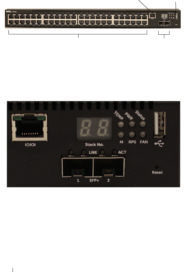
92 Hardware Overview
Figure 3-1. N2048 Switch with 48 10/100/1000BASE-T Ports (Front Panel)
In addition to the switch ports, the front panel of each model in the N2000
series includes the following ports:
•Console port
•USB port
Figure 3-2. N2024 Close-up
The N2024 front panel, shown in Figure 3-2, has status LEDs for over-
temperature alarm, internal power, and status on the top row. The bottom
row of status LEDs displays stack master, redundant power supply (RPS)
status and fan alarm status.
48 10/100/1000BASE-T Ports SFP+ Ports
Console Port USB Port

Hardware Overview 93
Figure 3-3. N2024P Close-up
The N2024P front panel, shown in Figure 3-3, has status LEDs for over-
temperature alarm, internal power and status on the top row. The bottom row
of status LEDs displays stack master, modular power supply (MPS) status and
fan alarm status.
Switch Ports
The N2024/N2024P front panel provides 24 Gigabit Ethernet
(10/100/1000BASE-T) RJ-45 ports that support auto-negotiation for speed,
flow control, and duplex. The N2024/N2024P models support two SFP+ 10G
ports. Dell-qualified SFP+ transceivers are sold separately.
The N2048/N2048P front panel provides 48 Gigabit Ethernet (10BASE-T,
100BASE-TX, 1000BASE-T) RJ-45 ports that support auto-negotiation for
speed, flow control, and duplex. The N2048/N2048P support two SFP+ 10G
ports. Dell-qualified SFP+ transceivers are sold separately.
The front-panel switch ports have the following characteristics:
• The switch automatically detects the difference between crossed and
straight-through cables on RJ-45 ports and automatically chooses the MDI
or MDIX configuration to match the other end.
• SFP+ ports support Dell-qualified transceivers. The default behavior is to
log a message and generate an SNMP trap on insertion or removal of an
optic that is not qualified by Dell. The message and trap can be suppressed
by using the
service unsupported-transceiver
command.

94 Hardware Overview
• RJ-45 ports support full-duplex mode 10/100/1000 Mbps speeds on
standard Category 5 UTP cable.
• SFP+ ports support SFP+ transceivers and SFP+ copper twin-ax
technology operating at 10G or 1G plus SFP transceivers operating at 1G.
• The N2024P/N2048P front panel ports support PoE (15.4W) and PoE+
(34.2W).
Console Port
The console port provides serial communication capabilities, which allows
communication using RS-232 protocol. The serial port provides a direct
connection to the switch and allows access to the CLI from a console
terminal connected to the port through the provided serial cable (with RJ45
YOST to female DB-9 connectors).
The console port is separately configurable and can be run as an asynchronous
link from 1200 baud to 115,200 baud.
The Dell CLI only supports changing the speed. The defaults are 9600 baud
rate, 8 data bits, No Parity, 1 Stop Bit, No Flow Control.
USB Port
The Type-A, female USB port supports a USB 2.0-compliant flash memory
drive. The Dell Networking switch can read or write to a flash drive with a
single partition formatted as FAT-32. You can use a USB flash drive to copy
switch configuration files and images between the USB flash drive and the
switch. You can also use the USB flash drive to move and copy configuration
files and images from one switch to other switches in the network. The
system does not support the deletion of files on USB flash drives.
The USB port does not support any other type of USB device.
Reset Button
The reset button is accessed through the pinhole and allows you to perform a
hard reset on the switch. To use the reset button, insert an unbent paper clip
or similar tool into the pinhole. When the switch completes the boot process
after the reset, it resumes operation with the most recently saved
configuration. Any changes made to the running configuration that were not
saved to the startup configuration prior to the reset are lost.
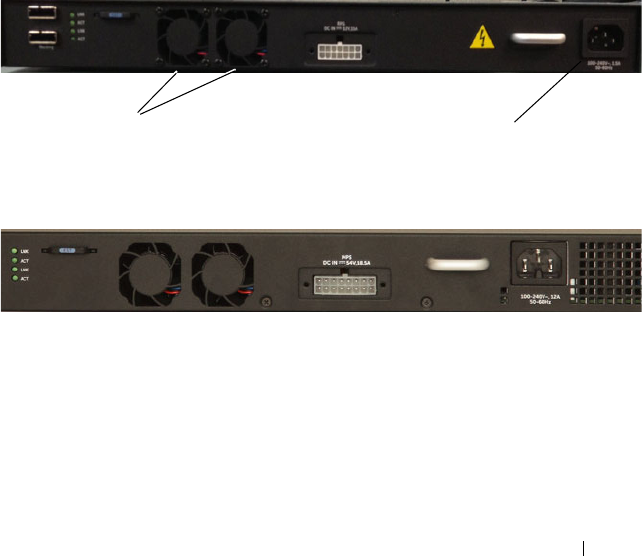
Hardware Overview 95
Port and System LEDs
The front panel contains light emitting diodes (LEDs) that indicate the
status of port links, power supplies, fans, stacking, and the overall system
status. See "N2000 LED Definitions" on page 97 for more information.
Stack Master LED and Stack Number Display
When a switch within a stack is the master unit, the stack master LED, which
is labeled M, is solid green. If the M LED is off, the stack member is not the
master unit. The Stack No. panel displays the unit number for the stack
member. If a switch is not part of a stack (in other words, it is a stack of one
switch), the M LED is illuminated, and the unit number is displayed.
N2000 Series Back Panel
The following images show the back panels of the N2000 switches.
Figure 3-4. N2000 Back Panel
Figure 3-5. N2024P/N2048P Back Panel
The term mini-SAS refers to the stacking port cable connections shown in
Figure 3-6. See "Managing a Switch Stack" on page 171 for information on
using the mini-SAS ports to connect switches.
Fan Vents AC Power Receptacle

96 Hardware Overview
Figure 3-6. N2048 Mini-SAS Stacking Ports and Fans
Power Supplies
N2024 and N2048
N2024 and N2048 series switches have an internal 100-watt power supply.
The additional redundant power supply (Dell Networking RPS720) provides
180 watts of power and gives full redundancy for the switch.
N2024P and N2048P
N2024P and N2048P switches have an internal 1000-watt power supply
feeding up to 24 PoE devices at full PoE+ power (850W). An additional
external power supply (MPS1000) provides 1000 watts and gives full power
coverage for all 48 PoE devices (1800W).
NOTE: PoE power is dynamically allocated. Not all ports will require the full PoE+
power.
CAUTION: Remove the power cable from the power supplies prior to removing
the power supply module itself. Power must not be connected prior to insertion in
the chassis.
Ventilation System
Two fans cool the N2000 switches.
Information Tag
The back panel includes a slide-out label panel that contains system
information, such as the Service Tag, MAC address, and so on.
Mini-SAS stacking ports

Hardware Overview 97
N2000 LED Definitions
This section describes the LEDs on the front and back panels of the switch.
Port LEDs
Each port on an N2000 switch includes two LEDs. One LED is on the left
side of the port, and the second LED is on the right side of the port. This
section describes the LEDs on the switch ports.
100/1000/10000Base-T Port LEDs
Each 100/1000/10000Base-T port has two LEDs. Figure 3-20 illustrates the
100/1000/10000Base-T port LEDs.
Figure 3-7. 100/1000/10000Base-T Port LEDs
Link/SPD Activity

98 Hardware Overview
Table 3-16 shows the 100/1000/10000Base-T port LED definitions.
Stacking Port LEDs
Table 3-1. 100/1000/10000Base-T Port Definitions
LED Color Definition
Link/SPD LED Off There is no link.
Solid yellow The port is operating at 10/100 Mbps.
Solid green The port is operating at 1000 Mbps.
Activity LED
(on non-PoE
switches)
Off There is no current transmit/receive activity.
Blinking green The port is actively transmitting/receiving.
Activity/PoE
LED (on PoE
switches)
Off There is no current transmit/receive activity
and PoE power is off.
Blinking green The port is actively transmitting/receiving and
PoE power is off.
Blinking yellow The port is actively transmitting/receiving and
PoE power is on.
Solid yellow There is no current transmit/receive activity
and PoE power is on.
Table 3-2. Stacking Port LED Definitions
LED Color Definition
Link LED Off There is no link.
Solid green The port is actively transmitting/receiving.
Activity LED Off There is no current transmit/receive activity.
Blinking green The port is actively transmitting/receiving.

Hardware Overview 99
System LEDs
The system LEDs, located on the back panel, provide information about the
power supplies, thermal conditions, and diagnostics.
Table 3-21 shows the System LED definitions for the N2000 series switches.
Table 3-3. Console Port LED Definitions
LED Color Definition
Link/SPD LED Off There is no link.
Solid green A link is present.
Table 3-4. System LED Definitions
LED Color Definition
Status Solid green Normal operation.
Blinking green The switch is booting
Solid red A critical system error has occurred.
Blinking red A noncritical system error occurred (fan or power
supply failure).
Power Off There is no power or the switch has experienced a
power failure.
Solid green Power to the switch is on.
Blinking green The switch locator function is enabled.
RPS (on
non-PoE
switches)
Off There is no redundant power supply (RPS).
Solid green Power to the RPS is on.
Solid red An RPS is detected but it is not receiving power.
EPS (on
PoE
switches)
Off There is no external power supply (EPS).
Solid green Power to the EPS is on.
Solid red An EPS is detected but it is not receiving power.
Fan Solid green The fan is powered and is operating at the expected
RPM.
Solid red A fan failure has occurred.

100 Hardware Overview
Power Consumption for N2000 Series PoE Switches
Table 3-5 shows power consumption data for the PoE-enabled switches.
The PoE power budget for each interface is controlled by the switch firmware.
The administrator can limit the power supplied on a port or prioritize power
to some ports over others. Table 3-6 shows power budget data.
Stack
master
Off The switch is in stand-alone mode.
Solid green The switch is master for the stack.
Temp Solid green The switch is operating below the threshold
temperature.
Solid red The switch temperature exceeds the threshold of 75°C.
Stack No. – Switch ID within the stack.
Table 3-5. Power Consumption
Model Input
Voltage
Power Supply
Configuration
Max Steady
Current
Consumption (A)
Max Steady
Power (W)
N2024P 100V Main PSU+EPS PSU 8.9 890.0
110V Main PSU+EPS PSU 8.3 913.0
120V Main PSU+EPS PSU 7.6 912.0
220V Main PSU+EPS PSU 4.0 880.0
240V Main PSU+EPS PSU 3.6 873.6
N2048P 100V Main PSU+EPS PSU 17.8 1780.0
110V Main PSU+EPS PSU 15.8 1740.2
120V Main PSU+EPS PSU 14.5 1740.0
220V Main PSU+EPS PSU 7.7 1687.4
240V Main PSU+EPS PSU 7.1 1704.0
Table 3-4. System LED Definitions (Continued)
LED Color Definition

Hardware Overview 101
Table 3-6. N2000 Series PoE Power Budget Limit
One PSU Support Two PSUs Support
Model
Name
System Power
Max. Dissipation
Max. PSU
Output Ability
POE+ Power
Turn-on Limitation
Max. PSUs
Output Ability
POE+ Power
Turn-on Limitation
N2024P 90W 1000W Power budget is
850W:
The total POE
supplied power
must not exceed
850W.
2000W Power budget is
1700W:
All PoE+ ports can
supply maximum
power.
N2048P 110W 1000W Power budget is
850W:
The total POE
supplied power
must not exceed
850W.
2000W Power budget is
1700W:
All PoE+ ports can
supply maximum
power.
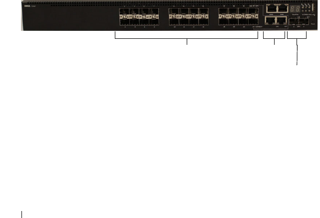
102 Hardware Overview
Dell Networking N3000 Series Switch Hardware
This section contains information about device characteristics and modular
hardware configurations for the N3000 series switches.
N3000 Series Front Panel
The N2000 series front panel includes the following features:
•Switch Ports
•Console Port
• Out-of-Band Management Port
•USB Port
•SFP+ Ports
• Reset Button
•Port and System LEDs
• Stack Master LED and Stack Number Display
The following images show the front panels of the switch models in the
N3000 series.
Figure 3-8. N3024F with 24 10/100/1000BASE-T Ports (Front Panel)
The N3000 series switch includes two combo ports. The combo ports are SFP
on the N3000 series and 1000BaseT on the N3024F switch.
Combo
Ports
10/100/1000BASE-T Auto-sensing
Full Duplex RJ-45 Ports SFP+
Ports
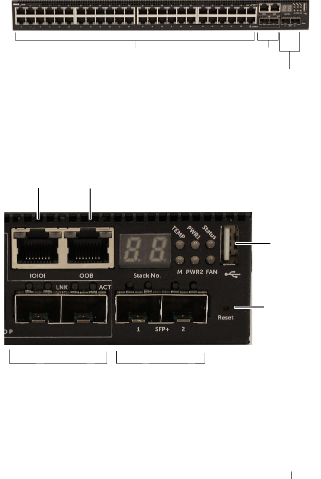
Hardware Overview 103
Figure 3-9. N3048 with 48 10/100/1000BASE-T Ports (Front Panel)
The additional ports are on the right side of the front panel, as shown in
Figure 3-9 and Figure 3-10 on page 103.
Figure 3-10. Additional N3000 Series Ports
The N3000 front panel above also contains a reset button (pinhole) and
several status LEDs. See Figure 3-10.
10/100/1000BASE-T Auto-sensing
Full Duplex RJ-45 Ports
Combo
Ports
SFP+
Ports
Combo Ports
Reset Button
USB Port
Console Port Out-of-Band Management Port
SFP+ Ports

104 Hardware Overview
The N3000 front panel also displays status LEDs for over-temperature alarm,
internal power supply 1 and switch status on the top row. The bottom row of
status LEDs displays stack master, internal power supply 2 and fan alarm.
Switch Ports
The N3024/N3024P front panel provides 24 Gigabit Ethernet
(10/100/1000BASE-T) RJ-45 ports that support auto-negotiation for speed,
flow control, and duplex. The N3024P models support two SFP+ 10G ports.
Dell-qualified SFP+ transceivers are sold separately.
The N3024F front panel provides 24 Gigabit Ethernet 100BASE-
FX/1000BASE-X SFP ports plus 2 1000BASE-T combo ports. Dell-qualified
SFP transceivers are sold separately.
The N3048/N3048P front panel provides 48 Gigabit Ethernet (10BASE-T,
100BASE-TX, 1000BASE-T) RJ-45 ports that support auto-negotiation for
speed, flow control, and duplex. The N3048/N3048P support two SFP+ 10G
ports. Dell-qualified SFP+ transceivers are sold separately.
The front-panel switch ports have the following characteristics:
• The switch automatically detects the difference between crossed and
straight-through cables on RJ-45 ports and automatically chooses the MDI
or MDIX configuration to match the other end.
• SFP+ ports support Dell-qualified transceivers. The default behavior is to
log a message and generate an SNMP trap on insertion or removal of an
optic that is not qualified by Dell. The message and trap can be suppressed
by using the
service unsupported-transceiver
command.
• RJ-45 ports support full-duplex mode 10/100/1000 Mbps speeds on
standard Category 5 UTP cable.
• SFP+ ports support SFP+ transceivers and SFP+ copper twin-ax
technology operating at 10G/1G plus SFP transceivers operating at 1G.
• The N3024P/N3048P front panel ports support PoE (15.4W) and PoE+
(34.2W).

Hardware Overview 105
Console Port
The console port provides serial communication capabilities, which allows
communication using RS-232 protocol. The serial port provides a direct
connection to the switch and allows access to the CLI from a console
terminal connected to the port through the provided serial cable (with RJ45
YOST to female DB-9 connectors).
The console port is separately configurable and can be run as an asynchronous
link from 1200 baud to 115,200 baud.
The Dell CLI only supports changing the speed.
The defaults are 9600 baud rate, 8 data bits, No Parity, 1 Stop Bit, No Flow
Control.
Out-of-Band Management Port
The Out-of-Band (OOB) management port is a 10/100/1000BASE-T
Ethernet port dedicated to remote switch management. Traffic on this port is
segregated from operational network traffic on the switch ports and cannot be
switched or routed to or from the operational network.
USB Port
The Type-A, female USB port supports a USB 2.0-compliant flash memory
drive. The Dell Networking switch can read or write to a flash drive with a
single partition formatted as FAT-32. You can use a USB flash drive to copy
switch configuration files and images between the USB flash drive and the
switch. You can also use the USB flash drive to move and copy configuration
files and images from one switch to other switches in the network. The
system does not support the deletion of files on attached USB flash drives.
The USB port does not support any other type of USB device.
Reset Button
The reset button is accessed through the pinhole and allows you to perform a
hard reset on the switch. To use the reset button, insert an unbent paper clip
or similar tool into the pinhole. When the switch completes the boot process
after the reset, it resumes operation with the most recently saved
configuration. Any changes made to the running configuration that were not
saved to the startup configuration prior to the reset are lost.

106 Hardware Overview
Port and System LEDs
The front panel contains light emitting diodes (LEDs) that indicate the
status of port links, power supplies, fans, stacking, and the overall system
status.
For information about the status that the LEDs indicate, see the
User’s
Configuration Guide.
Stack Master LED and Stack Number Display
When a switch within a stack is the master unit, the stack master LED, which
is labeled M, is solid green. If the M LED is off, the stack member is not the
master unit. The Stack No. panel displays the unit number for the stack
member. If a switch is not part of a stack (in other words, it is a stack of one
switch), the M LED is illuminated, and the unit number is displayed.
N3000 Series Back Panel
The following images show the back panels of the N3000 switches.
Figure 3-11. N3000 Back Panel
Figure 3-12. N3024P/N3048P Back Panel
Dual 10G Slots for SFP+ or
10GBASE-T Modules
AC Power
Receptacle
Fan Vents

Hardware Overview 107
Figure 3-13. N3048 Mini-SAS Stacking Ports Close-up
The term mini-SAS refers to the stacking port cable connections shown in
Figure 3-13. See "Managing a Switch Stack" on page 171 for information on
using the mini-SAS ports to connect switches.
Expansion Slots for Plug-in Modules
One expansion slot is located on the back of the N3000 models and can
support the following modules:
•10GBASE-T module
•SFP+ module
Each plug-in module has two ports. The plug-in modules include hot-swap
support, so you do not need to reboot the switch after you install a new
module.
Power Supplies
N3024, N3024F and N3048
N3024 series, N3024F and N3048 switches support two 200-watt Field
Replaceable Unit (FRU) power supplies which give full power redundancy for
the switch. The N3024, N3024F, and N3048 switches offer the V-lock feature
for users desiring the need to eliminate accidental power disconnection. The
V-lock receptacle on the
Power Supply Unit (
PSU) allows for the use of a
power cord that has the V-lock feature to create an integral secure locking
connection.
Mini-SAS stacking ports

108 Hardware Overview
N3024P and N3048P
Dell Networking N3024P and N3048P switches support one or two 1100-watt
FRU power supplies. The N3024P switch is supplied with a single 715-watt
power supply (the default configuration) and supports an additional
1100-watt supply. For the N3048P switch, a single 1100-watt power supply is
supplied and another 1100 watt power supply can be added.
A single 1100-watt power supply can feed up to 24 PoE devices at full PoE+
power (950W). Dual-equipped switches will feed up to 48 PoE devices at full
PoE+ power (1800W), as well as provide power supply redundancy.
NOTE: PoE power is dynamically allocated by default. Not all ports will require the
full PoE+ power.
CAUTION: Remove the power cable from the power supplies prior to removing
the power supply module itself. Power must not be connected prior to insertion in
the chassis.
Ventilation System
Two fans cool the N3000 switches. The N3000 switches additionally have a
fan in each internal power supply. The N3000 fan is a FRU.
Information Tag
The back panel includes a slide-out label panel that contains system
information, such as the Service Tag, MAC address, and so on.
Hardware Overview 109
LED Definitions
This section describes the LEDs on the front and back panels of the switch.
Port LEDs
Each port on an N3000 series switch includes two LEDs. One LED is on the
left side of the port, and the second LED is on the right side of the port. This
section describes the LEDs on the switch ports.
100/1000/10000Base-T Port LEDs
Each 100/1000/10000Base-T port has two LEDs. Figure 3-20 illustrates the
100/1000/10000Base-T port LEDs.
Figure 3-14. 100/1000/10000Base-T Port LEDs
Link/SPD Activity

110 Hardware Overview
Table 3-16 shows the 100/1000/10000Base-T port LED definitions.
Module Bay LEDs
The following tables describe the purpose of each of the module bay LEDs
when SFP+ and 10GBaseT modules are used.
Table 3-7. 100/1000/10000Base-T Port Definitions
LED Color Definition
Link/SPD LED Off There is no link.
Solid yellow The port is operating at 10/100 Mbps.
Solid green The port is operating at 1000 Mbps.
Activity LED
(on non-PoE
switches)
Off There is no current transmit/receive activity.
Blinking green The port is actively transmitting/receiving.
Activity/PoE
LED (on PoE
switches)
Off There is no current transmit/receive activity
and PoE power is off.
Blinking green The port is actively transmitting/receiving and
PoE power is off.
Blinking yellow The port is actively transmitting/receiving and
PoE power is on.
Solid yellow There is no current transmit/receive activity
and PoE power is on.
Table 3-8. SFP+ Module LED Definitions
LED Color Definition
Link/SPD LED Off There is no link.
Solid green The port is operating at 10 Gbps.
Solid amber The port is operating at 1000 Mbps.
Activity LED Off There is no current transmit/receive activity.
Blinking green The port is actively transmitting/receiving.

Hardware Overview 111
Table 3-9. 10GBase-T Module LED Definitions
LED Color Definition
Link/SPD LED Off There is no link.
Solid green The port is operating at 10 Gbps.
Solid amber The port is operating at 100/1000 Mbps.
Activity LED Off There is no current transmit/receive activity.
Blinking green The port is actively transmitting/receiving.
Table 3-10. Stacking Port LED Definitions
LED Color Definition
Link LED Off There is no link.
Solid green The port is actively transmitting/receiving.
Activity LED Off There is no current transmit/receive activity.
Blinking green The port is actively transmitting/receiving.
Table 3-11. OOB Port LED Definitions
LED Color Definition
Link/SPD LED Off There is no link.
Solid green The port is actively transmitting/receiving at
1000 Mbps.
Solid amber The port is actively transmitting/receiving at
10/100 Mbps.
Activity LED Off There is no current transmit/receive activity.
Blinking green The port is actively transmitting/receiving.

112 Hardware Overview
System LEDs
The system LEDs, located on the back panel, provide information about the
power supplies, thermal conditions, and diagnostics.
Table 3-21 shows the System LED definitions for the N3000 series switches.
Table 3-12. Console Port LED Definitions
LED Color Definition
Link/SPD LED Off There is no link.
Solid green A link is present.
Table 3-13. System LED Definitions
LED Color Definition
Status Solid green Normal operation.
Blinking green The switch is booting
Solid red A critical system error has occurred.
Blinking red A noncritical system error occurred (fan or power
supply failure).
Power 1,
Power 2
Off There is no power or the switch has experienced a
power failure.
Solid green Power to the switch is on.
Blinking green The switch locator function is enabled.
Fan Solid green The fan is powered and is operating at the expected
RPM.
Solid red A fan failure has occurred.
Stack
master
Off The switch is in stand-alone mode.
Solid green The switch is master for the stack.
Temp Solid green The switch is operating below the threshold
temperature.
Solid red The switch temperature exceeds the threshold of 75°C.
Stack No. – Switch ID within the stack.

Hardware Overview 113
Power Consumption for N3000 Series PoE Switches
Table 3-14 shows power consumption data for the PoE-enabled switches.
The PoE power budget for each interface is controlled by the switch firmware.
The administrator can limit the power supplied on a port or prioritize power
to some ports over others. Table 3-15 shows the power budget data.
Table 3-14. N3000 Series Power Consumption
Model Input
Voltage
Power Supply
Configuration
Max Steady
Current
Consumption (A)
Max Steady
Power (W)
N3024P 100V PSU1+PSU2 13.1 1310.0
110V PSU1+PSU2 11.7 1287.0
120V PSU1+PSU2 10.6 1272.0
220V PSU1+PSU2 5.6 1232.0
240V PSU1+PSU2 5.2 1240.8
N3048P 100V PSU1+PSU2 21.8 2180.0
110V PSU1+PSU2 19.5 2145.0
120V PSU1+PSU2 17.8 2136.0
220V PSU1+PSU2 9.31 2048.2
240V PSU1+PSU2 8.6 2064.0

114 Hardware Overview
Table 3-15. N3000 Series PoE Power Budget Limit
One PSU Support Two PSUs Support
Model
Name
System Power
Max. Dissipation
Max. PSU
Output Ability
POE+ Power
Turn-on Limitation
Max. PSUs
Output Ability
POE+ Power
Turn-on Limitation
N3024P 110W 715W Power budget is
550W:
The total POE
supplied power
must not exceed
550W.
715W Power budget is
1100W:
All PoE+ ports can
supply maximum
power.
N3048P 140W 1100W Power budget is
950W:
The total POE
supplied power
must not exceed
950W.
2200W Power budget is
1900W:
All PoE+ ports can
supply maximum
power.

Hardware Overview 115
Dell Networking N4000 Series Switch Hardware
NOTE: PowerConnect 8100 has been renamed N4000. Both PowerConnect 8100
and N4000 can run firmware versions 6.1 and beyond. N4000 cannot run firmware
prior to version 6.1.
This section contains information about device characteristics and modular
hardware configurations for the N4000 series switches.
Front Panel
The N4000 series front panel includes the following features:
•Switch ports
• Module bay that supports the following modules:
– 2 x 40 Gig QSFP (each QSFP may be configured as 4 x 10 Gig ports)
–4 x SFP+ module
– 4 x 10GBaseT module
See "Hot-Pluggable Interface Modules" on page 117 for more information.
•USB port
• Reset button
• Port and system LEDs
•Stack LED
The N4032 front panel provides 32 x 10GbE copper ports that support up to
100M of CAT-6A UTP cabling. The N4032F provides 32 SFP+ ports
supporting SFP+ and SFP transceivers.
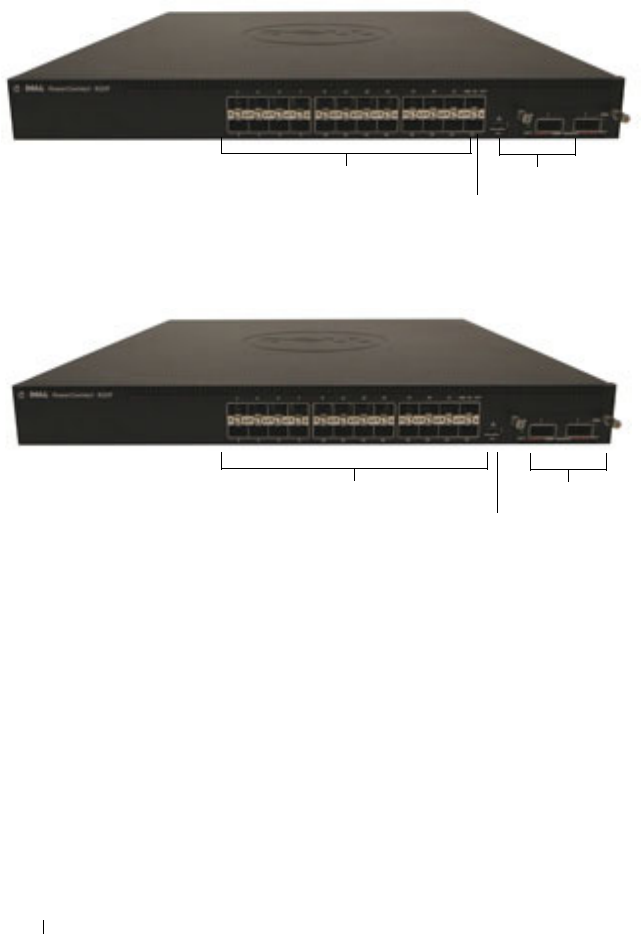
116 Hardware Overview
Figure 3-15. N4024 Front Panel
Figure 3-16. N4024F Front Panel
N4032 and N4032F switches can be stacked with other N4000 switches using
10G or 40G SFP+ or QSFP modules in the module bay.
The N4064 front panel provides 64 x 10GbE copper ports and two fixed
QSFP ports, each supporting 4 x 10G or 1 x 40G connections. The N4064F
front panel provides 64 SFP+ ports supporting SFP+ and SFP transceivers
plus two fixed QSFP ports, each supporting 4 x 10G or 1 x 40G connections.
10GbE Copper Ports Module bay
USB port
10GbE Fiber Ports Module bay
USB port
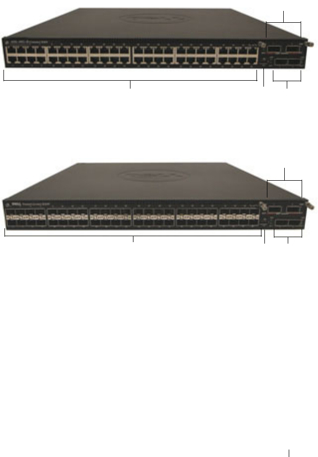
Hardware Overview 117
Figure 3-17. N4064 Front Panel
Figure 3-18. N4064F Front Panel
The N4064 and N4064F switches can be stacked with other N4000 switches
using the 10G or 40G SFP+ or QSFP modules in the module bay or fixed
QSFP ports.
Hot-Pluggable Interface Modules
The N4032, N4032F, N4064, and N4064F switches support the following hot-
pluggable interface modules:
•
N4000
-QSFP — 2 x 40G QSFP port module - defaults to 2 x 40G
•
N4000
-SFP+ — 4 x SFP+ port module - defaults to 4 x 10G mode
•
N4000
-10GBT — 4 x 10GBase-T ports module - defaults to 4 x 10G mode
• Blank module — defaults to 10G mode
10GbE Copper Ports USB port Fixed QSFP
ports
Module bay
10GbE Fiber Ports Fixed QSFP
ports
Module bay
USB port

118 Hardware Overview
A reboot is necessary when a hot-pluggable module is replaced with a module
of different type. Specifically, changing from a 40G module to a 10G module
or from a 10G module to a 40G module requires a reboot. Plug-in modules
with any port configured as a stacking port are not hot-swappable. Remove
the stack-port configuration from a slot before plugging in a module.
You must execute a no slot or clear config command prior to inserting the
new module. Note that changing the role of a port from stacking to Ethernet
or vice-versa also requires a switch reboot.
If a no slot command is not issued prior to inserting a module, a message
such as the following will appear:
Card Mismatch: Unit:1 Slot:1 Inserted-Card: Dell 2
Port QSFP Expansion Card Config-Card: Dell 4 Port
10GBase-T Expansion Card
The following sections provides details on each module.
Quad-Port SFP (QSFP) Uplink Module
The QSFP module supports features four ports that support 10G SFP+
transceivers. The QSFP module supports the following features:
• Four 10G ports with quad-breakout/QBO cable or one 40G port
• Front-panel port status LEDs
The QSFP interfaces can be used for stacking. Stacking is supported at
distances of up to 100M.
Quad-Port SFP+ Uplink Module
The N4000-SFP+ module features four SFP+ ports, each providing the
following features:
• SFP+ optical interfaces
• SFP+ copper twinax interface
• Front-panel port status LEDs
The SFP+ connections can be used for stacking. Stacking is supported at
distances of up to 100M.

Hardware Overview 119
10GBase-T Copper Uplink Module
The 10GBase-T copper module features four copper ports that can support
10GbE/1GbE/100MbE switching and provides following features:
• Complies with IEEE802.3z, IEEE 802.3, IEEE802.3u, IEEE802.3ab,
IEEE802.3az, IEEE802.3an
• Four 10GBase-T/1GBase-T/100MBase-T copper ports.
• Front panel port status LEDs
USB Port
The Type-A, female USB port supports a USB 2.0-compliant flash memory
drive. The N4000 switch can read or write to a flash drive with a single
partition formatted as FAT-32. You can use a USB flash drive to copy switch
configuration files and images between the USB flash drive and the switch.
You can also use the USB flash drive to move and copy configuration files and
images from one switch to other switches in the network. Deletion of files on
the USB drive is not supported.
The USB port does not support any other type of USB device.
Port and System LEDs
The front panel contains light emitting diodes (LEDs) to indicate port status.
For information about the status that the LEDs indicate, see "LED
Definitions" on page 121.
SFP+ and QSFP+ Ports
SFP+ and QSFP+ ports support Dell-qualified transceivers. The default
behavior is to log a message and generate an SNMP trap on insertion or
removal of an optic that is not qualified by Dell. This message and trap can be
suppressed by using the service unsupported-transceiver command.
N4000 Back Panel
The N4000 series back panel has the following features:
•Console port
• Out-of-band management port
• Power Supplies

120 Hardware Overview
• Ventilation System
The following image show the back panel of the N4000 series switches.
Figure 3-19. N4000 Series Back Panel
Console Port
The console port is for management through a serial interface. This port
provides a direct connection to the switch and allows you to access the CLI
from a console terminal connected to the port through the provided serial
cable (RJ-45 to female DB-9 connectors).
The console port supports asynchronous data of eight data bits, one stop bit, no
parity bit, and no flow control. The default baud rate is 9600 bps.
Out-of-Band Management Port
The Out-of-Band (OOB) management port is a 10/100/1000BASE-T
Ethernet port dedicated to remote switch management. Traffic on this port is
segregated from operational network traffic on the switch ports and cannot be
switched or routed to or from the operational network.
Power Supplies
Each N4000 series switch has two power supplies for redundant or
loadsharing operation. Each power supply can support 300W.
AC powerAC power OOB Ethernet port
RJ-45 serial console port
Fans
Hardware Overview 121
Ventilation System
The N4000 series switches have two fans. Each switch also has four thermal
sensors and a fan speed controller, which can be used to control FAN speeds.
You can verify operation by observing the LEDs.
LED Definitions
This section describes the LEDs on the front and back panels of the switch.
Port LEDs
Each port on a N4000 series switch includes two LEDs. One LED is on the
left side of the port, and the second LED is on the right side of the port. This
section describes the LEDs on the switch ports.
100/1000/10000Base-T Port LEDs
Each 100/1000/10000Base-T port has two LEDs. Figure 3-20 illustrates the
100/1000/10000Base-T port LEDs.
Figure 3-20. 100/1000/10000Base-T Port LEDs
CAUTION: Remove the power cable from the modules prior to removing the
module itself. Power must not be connected prior to insertion in the chassis.
Link Activity

122 Hardware Overview
Table 3-16 shows the 100/1000/10000Base-T port LED definitions.
Module Bay LEDs
The following tables describe the purpose of each of the module bay LEDs
when SFP+, 10GBase-T, and QSFP modules are used.
Table 3-16. 100/1000/10000Base-T Port Definitions
LED Color Definition
Link LED Off There is no link.
Solid green The port is operating at 10 Gbps.
Solid amber The port is operating at 100/1000 Mbps.
Activity LED Off There is no current transmit/receive activity.
Blinking green The port is actively transmitting/receiving.
Table 3-17. SFP+ Module LED Definitions
LED Color Definition
Link LED Off There is no link.
Solid green The port is operating at 10 Gbps.
Solid amber The port is operating at 100/1000 Mbps.
Activity LED Off There is no current transmit/receive activity.
Blinking green The port is actively transmitting/receiving.
Table 3-18. 10GBase-T Module LED Definitions
LED Color Definition
Link LED Off There is no link.
Solid green The port is operating at 10 Gbps.
Solid amber The port is operating at 100/1000 Mbps.
Activity LED Off There is no current transmit/receive activity.
Blinking green The port is actively transmitting/receiving.

Hardware Overview 123
Out-of-Band Ethernet Management Port LEDs
Table 3-20 shows the LED definitions for the OOB Ethernet management
port.
System LEDs
The system LEDs, located on the back panel, provide information about the
power supplies, thermal conditions, and diagnostics.
Table 3-19. QSFP Module LED Definitions
LED Color Definition
Link LED Off There is no link.
Solid green The port is operating at 40 Gbps.
Solid amber The port is operating at other speeds.
Activity LED Off There is no current transmit/receive activity.
Blinking green The port is actively transmitting/receiving.
Table 3-20. OOB Ethernet Management Port LED Definitions
LED Color Definition
Link LED Off There is no link.
Solid green The port is operating at 1000 Mbps.
Solid amber The port is operating at 10/100 Mbps.
Activity LED Off There is no current transmit/receive activity.
Blinking green The port is actively transmitting/receiving.

124 Hardware Overview
Table 3-21 shows the System LED definitions for the N4000 series switches.
Table 3-21. System LED Definitions—N4000 Series Switches
LED Color Definition
System Blinking blue The switch is booting
Solid red A critical system error has occurred.
Blinking red A noncritical system error occurred (fan or power
supply failure).
Temp Off The switch is operating at normal temperature.
Solid amber The thermal sensor’s system temperature threshold of
75°C has been exceeded.
Diag Off The switch is operating normally
Blinking green A diagnostic test is running.
Fan Solid green The fan is powered and is operating at the expected
RPM.
Solid red A fan failure has occurred.
Stack Solid blue The switch is in stacking master mode.
Solid amber The switch is in stacking slave mode.
Off The switch is in stand-alone mode.
Locator Blinking green The locator function is enabled.
Solid green The locator function is disabled.

Hardware Overview 125
Switch MAC Addresses
The switch allocates MAC addresses from the Vital Product Data information
stored locally in flash. MAC addresses are used as follows:
Shown below are three commands that display the MAC addresses used by
the switch:
console#show system
System Description: Dell Ethernet Switch
System Up Time: 0 days, 00h:05m:11s
System Contact:
System Name:
System Location:
Burned In MAC Address: 001E.C9F0.004D
System Object ID: 1.3.6.1.4.1.674.10895.3042
System Model ID: N4032
Machine Type: N4032
Temperature Sensors:
Unit Description Temperature Status
(Celsius)
---- ----------- ----------- ------
1 MAC 32 Good
1 CPU 31 Good
1 PHY (left side) 26 Good
1 PHY (right side) 29 Good
Fans:
Unit Description Status
---- ----------- ------
1 Fan 1 OK
1 Fan 2 OK
1 Fan 3 OK
1 Fan 4 OK
1 Fan 5 OK
1 Fan 6 No Power
Power Supplies:
Unit Description Status Average Current Since
Power Power Date/Time
(Watts) (Watts)
---- ----------- ----------- ---------- -------- -------------------
Table 3-22. MAC Address Use
Base switch address, Layer 2
Base + 1 Out-of-band port (not available on N20xx switches)
Base + 3 Layer 3

126 Hardware Overview
1 System OK 42.0 43.4
1 Main OK N/A N/A 04/06/2001 16:36:16
1 Secondary No Power N/A N/A 01/01/1970 00:00:00
USB Port Power Status:
----------------------
Device Not Present
console#show ip interface out-of-band
IP Address..................................... 10.27.21.29
Subnet Mask.................................... 255.255.252.0
Default Gateway................................ 10.27.20.1
Configured IPv4 Protocol....................... DHCP
Burned In MAC Address.......................... 001E.C9F0.004E
console#show ip interface vlan 1
Routing Interface Status....................... Down
Primary IP Address............................. 1.1.1.2/255.255.255.0
Method......................................... Manual
Routing Mode................................... Enable
Administrative Mode............................ Enable
Forward Net Directed Broadcasts................ Disable
Proxy ARP...................................... Enable
Local Proxy ARP................................ Disable
Active State................................... Inactive
MAC Address.................................... 001E.C9F0.0050
Encapsulation Type............................. Ethernet
IP MTU......................................... 1500
Bandwidth...................................... 10000 kbps
Destination Unreachables....................... Enabled
ICMP Redirects................................. Enabled

Using Dell OpenManage Switch Administrator 127
4
Using Dell OpenManage Switch
Administrator
This section describes how to use the Dell OpenManage Switch
Administrator application. The topics covered in this section include:
• About Dell OpenManage Switch Administrator
• Starting the Application
• Understanding the Interface
• Using the Switch Administrator Buttons and Links
• Defining Fields
About Dell OpenManage Switch Administrator
Dell OpenManage Switch Administrator is a web-based tool to help you
manage and monitor a Dell Networking N2000, N3000, and N4000 series
switches. Table 4-1 lists the web browsers that are compatible with Dell
OpenManage Switch Administrator. The browsers have been tested on a PC
running the Microsoft Windows operating system.
Table 4-1. Compatible Browsers
Browser Version
Internet Explorer v9
Mozilla Firefox v14
Safari v5.0
Chrome v21
NOTE: Additional operating systems and browsers might be compatible but have
not been explicitly tested with Dell OpenManage Switch Administrator.
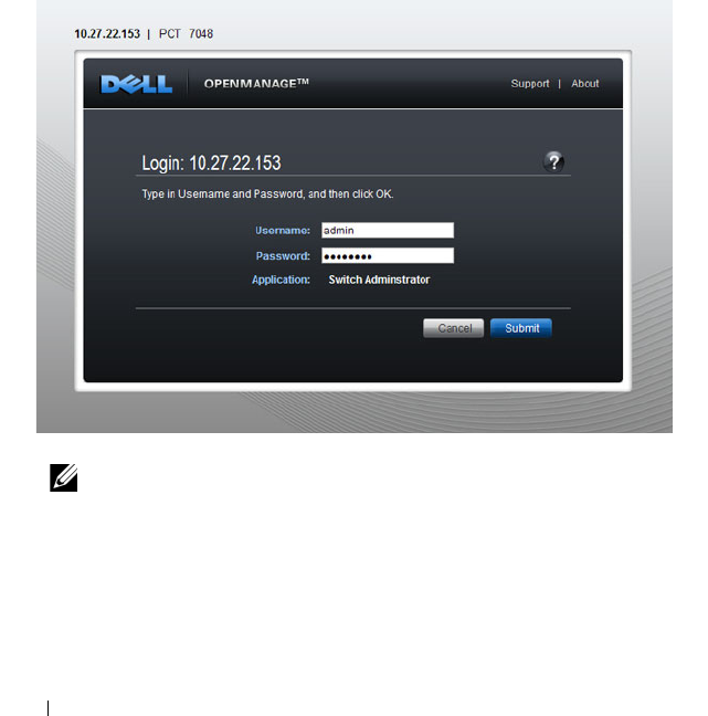
128 Using Dell OpenManage Switch Administrator
Starting the Application
To access the Dell OpenManage Switch Administrator and log on to the
switch:
1
Open a web browser.
2
Enter the IP address of the switch in the address bar and press <Enter>.
For information about assigning an IP address to a switch, see "Setting the
IP Address and Other Basic Network Information" on page 147.
3
When the
Login
window displays, enter a user name and password.
Passwords are both case sensitive and alpha-numeric.
Figure 4-1. Login Screen
4
Click
Submit
.
NOTE: The switch is not configured with a default user name or password.
You must connect to the CLI by using the console port to configure the initial
user name and password. For information about connecting to the console,
see "Console Connection" on page 135. For information about creating a user
and password, see "Configuring Authentication, Authorization, and
Accounting" on page 207.

Using Dell OpenManage Switch Administrator 129
5
The
Dell OpenManage
Switch Administrator
home page displays.
The home page is the
Device Information
page, which contains a
graphical representation of the front panel of the switch. For more
information about the home page, see "Device Information" on page 249.
Understanding the Interface
The Dell OpenManage Switch Administrator interface contains the following
components:
• Navigation panel — Located on the left side of the page, the navigation
pane provides an expandable view of features and their components.
• Configuration and status options — The main panel contains the fields
you use to configure and monitor the switch.
• Page tabs — Some pages contain tabs that allow you to access additional
pages related to the feature.
• Command buttons — Command buttons are located at the bottom of the
page. Use the command buttons to submit changes, perform queries, or
clear lists.
• Save, Print, Refresh, and Help buttons — These buttons appear on the
top-right side of the main panel and are on every page.
• Support, About, and Logout links — These links appear at the top of every
page.
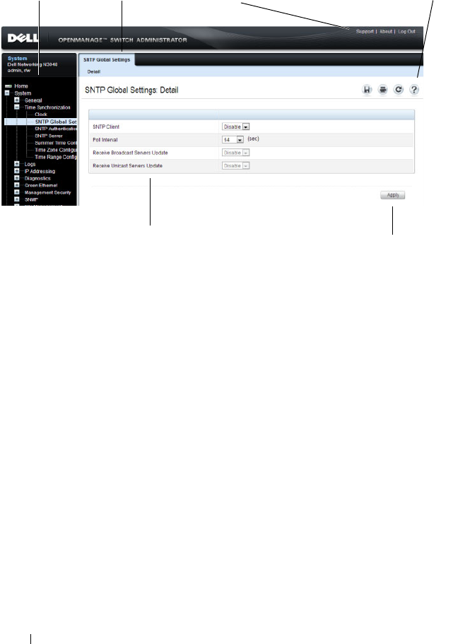
130 Using Dell OpenManage Switch Administrator
Figure 4-2. Switch Administrator Components
Navigation Panel Page Tabs Links Save, Print, Refresh, Help
Configuration and Status Options Command Button

Using Dell OpenManage Switch Administrator 131
Using the Switch Administrator Buttons and Links
Table 4-2 describes the buttons and links available from the
Dell
OpenManage
Switch Administrator
interface.
Table 4-2. Button and Link Descriptions
Button or Link Description
Support Opens the Dell Support page at support.dell.com
About Contains the version and build number and Dell copyright
information.
Log Out Logs out of the application and returns to the login screen.
Save Saves the running configuration to the startup configuration.
When you click Apply, changes are saved to the running
configuration. When the system boots, it loads the startup
configuration. Any changes to the running configuration that were
not saved to the startup configuration are lost across a power cycle.
Print Opens the printer dialog box that allows you to print the current
page. Only the main panel prints.
Refresh Refreshes the screen with the current information.
Help Online help that contains information to assist in configuring and
managing the switch. The online help pages are context sensitive.
For example, if the IP Addressing page is open, the help topic for
that page displays if you click Help.
Apply Updates the running configuration on the switch with the changes.
Configuration changes take effect immediately.
Clear Resets statistic counters and log files to the default configuration.
Query Queries tables.
Left arrow and
Right arrow
Moves information between lists.
NOTE: A few pages contain a button that occurs only on that page. Page-specific
buttons are described in the sections that pertain to those pages.
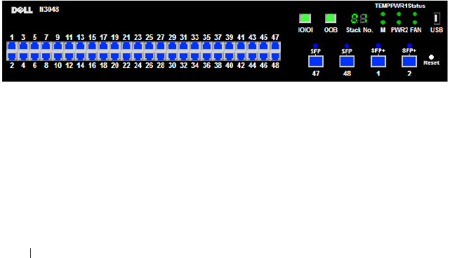
132 Using Dell OpenManage Switch Administrator
Defining Fields
User-defined fields can contain 1–159 characters, unless otherwise noted on
the Dell OpenManage Switch Administrator web page.
All characters may be used except for the following:
•\
•/
•:
•*
•?
•<
•>
•|
Understanding the Device View
The Device View shows various information about switch. This graphic
appears on the OpenManage Switch Administrator Home page, which is the
page that displays after a successful login. The graphic provides information
about switch ports and system health.
Figure 4-3. Dell Networking N3048 Device View
Using the Device View Port Features
The switching-port coloring indicates if a port is currently active. Green
indicates that the port has a link, red indicates that an error has occurred on
the port, and blue indicates that the link is down. Each port image is a
hyperlink to the Port Configuration page for the specific port.

Using Dell OpenManage Switch Administrator 133
Using the Device View Switch Locator Feature
The Device View graphic includes a Locate button and a drop-down menu of
timer settings. When you click Locate, the switch locator LED on the back
panel of the switch blinks for the number of seconds selected from the timer
menu. The green, blinking LED on the back of the switch can help you or a
technician near the switch identify the physical location of the switch within
a room or rack full of switches. After you click the Locate button it turns
green and remains green while the LED is blinking.
NOTE: You can also issue the locate command from the CLI to enable the
locator LED.

134 Using Dell OpenManage Switch Administrator

Using the Command-Line Interface 135
5
Using the Command-Line Interface
This section describes how to use the Command-Line Interface (CLI) on a
Dell Networking N2000, N3000, and N4000 series switches.
The topics covered in this section include:
• Accessing the Switch Through the CLI
• Understanding Command Modes
• Entering CLI Commands
Accessing the Switch Through the CLI
The CLI provides a text-based way to manage and monitor the Dell
Networking N2000, N3000, and N4000 series switches. You can access the
CLI by using a direct connection to the console port or by using a Telnet or
SSH client.
To access the switch by using Telnet or Secure Shell (SSH), the switch must
have an IP address, and the management station you use to access the device
must be able to ping the switch IP address.
For information about assigning an IP address to a switch, see "Setting the IP
Address and Other Basic Network Information" on page 147.
Console Connection
Use the following procedures to connect to the CLI by connecting to the
console port. For more information about creating a serial connection, see the
Getting Started Guide
available at support.dell.com/manuals.
1
Connect the DB-9 connector of the supplied serial cable to a management
station, and connect the RJ-45 connector to the switch console port.
On N2000 and N3000 series switches, the console port is located on the
right side of the front panel and is labeled with the
|O|O|
symbol. On the
N4000 series switches, it is located on the back panel above the OOB
Ethernet port.

136 Using the Command-Line Interface
2
Start the terminal emulator, such as
Microsoft HyperTerminal
, and select
the appropriate serial port (for example, COM 1) to connect to the
console.
3
Configure the management station serial port with the following settings:
• Data rate — 9600 baud.
• Data format — 8 data bits
•Parity — None
• Stop bits — 1
• Flow control — None
4
Power on the switch (or stack).
After the boot process completes, the
console>
prompt displays, and
you can enter commands.
Telnet Connection
Telnet is a terminal emulation TCP/IP protocol. ASCII terminals can be
virtually connected to the local device through a TCP/IP protocol network.
Telnet connections are enabled by default, and the Telnet port number is 23.
The switch supports up to four simultaneous Telnet sessions. All CLI
commands can be used over a Telnet session.
To connect to the switch using Telnet, the switch must have an IP address,
and the switch and management station must have network connectivity. You
can use any Telnet client on the management station to connect to the
switch.
NOTE: For a stack of switches, be sure to connect to the console port on the
Master switch. The Master LED (M) is illuminated on the stack Master.
NOTE: By default, no authentication is required for console access.
However, if an authentication method has been configured for console port
access, the User: login prompt displays.
NOTE: SSH, which is more secure than Telnet, is disabled by default.

Using the Command-Line Interface 137
You can also initiate a Telnet session from the OpenManage Switch
Administrator. For more information, see "Initiating a Telnet Session from the
Web Interface" on page 288.
Understanding Command Modes
The CLI groups commands into modes according to the command function.
Each of the command modes supports specific software commands. The
commands in one mode are not available until you switch to that particular
mode, with the exception of the User EXEC mode commands. You can
execute the User EXEC mode commands in the Privileged EXEC mode.
To display the commands available in the current mode, enter a question
mark (?) at the command prompt. In each mode, a specific command is used
to navigate from one command mode to another.
The main command modes include the following:
• User EXEC — Commands in this mode permit connecting to remote
devices, changing terminal settings on a temporary basis, performing basic
tests, and listing system information.
• Privileged EXEC — Commands in this mode permit you to view all switch
settings and to enter the global configuration mode.
• Global Configuration — Commands in this mode manage the device
configuration on a global level and apply to system features, rather than to
a specific protocol or interface.
• Interface Configuration — Commands in this mode configure the settings
for a specific interface or range of interfaces.
• VLAN Configuration — Commands in this mode create and remove
VLANs and configure IGMP/MLD Snooping parameters for VLANs.
The CLI includes several additional command modes. For more information
about the CLI command modes, including details about all modes, see the
CLI Reference Guide
.
Table 5-1 describes how to navigate between CLI Command Mode and lists
the prompt that displays in each mode.

138 Using the Command-Line Interface
Table 5-1. Command Mode Overview
Command Mode Access Method Command Prompt Exit or Access
Previous Mode
User EXEC The user is
automatically in
User EXEC
mode unless the
user is defined as
a privileged user.
console> logout
Privileged EXEC From User
EXEC mode,
enter the enable
command
console# Use the exit
command, or press
Ctrl-Z to return to
User EXEC mode.
Global
Configuration
From Privileged
EXEC mode, use
the configure
command.
console(config)# Use the exit
command, or press
Ctrl-Z to return to
Privileged EXEC
mode.
Interface
Configuration
From Global
Configuration
mode, use the
interface
command and
specify the
interface type
and ID.
console(config-
if)#
To exit to Global
Configuration
mode, use the exit
command, or press
Ctrl-Z to return to
Privileged EXEC
mode.

Using the Command-Line Interface 139
Entering CLI Commands
The switch CLI uses several techniques to help you enter commands.
Using the Question Mark to Get Help
Enter a question mark (?) at the command prompt to display the commands
available in the current mode.
console(config-vlan)#?
exit To exit from the mode.
help Display help for various special keys.
ip Configure IP parameters.
ipv6 Configure IPv6 parameters.
protocol Configure the Protocols associated with
particular Group Ids.
vlan Create a new VLAN or delete an existing
VLAN.
Enter a question mark (?) after each word you enter to display available
command keywords or parameters.
console(config)#vlan ?
<vlan-list> <1-4093> - separate non-consecutive IDs
with ',' and no spaces; Use '-' for
range.
protocol Configure Protocol Based VLAN
parameters.
If the help output shows a parameter in angle brackets, you must replace the
parameter with a value.
console#telnet ?
<ip-address|hostname> Enter the valid host IP
address or Host Name.

140 Using the Command-Line Interface
If there are no additional command keywords or parameters, or if additional
parameters are optional, the following message appears in the output:
<cr> Press enter to execute the command.
You can also enter a question mark (?) after typing one or more characters of a
word to list the available command or parameters that begin with the letters,
as shown in the following example:
console#show po?
policy-map port ports
Using Command Completion
The CLI can complete partially entered commands when you press the
<Tab> or <Space> key.
console#show run<Tab>
console#show running-config
If the characters you entered are not enough for the switch to identify a single
matching command, continue entering characters until the switch can
uniquely identify the command. Use the question mark (?) to display the
available commands matching the characters already entered.
Entering Abbreviated Commands
To execute a command, you need to enter enough characters so that the
switch can uniquely identify a command. For example, to enter Global
Configuration mode from Privileged EXEC mode, you can enter conf instead
of configure.
console#conf
console(config)#
Negating Commands
For many commands, the prefix keyword no is entered to cancel the effect of
a command or reset the configuration to the default value. Many
configuration commands have this capability.

Using the Command-Line Interface 141
Command Output Paging
Lines are printed on the screen up to the configured terminal length limit
(default 24). Use the space bar to show the next page of output or the carriage
return to show the next line of output. Setting the terminal length to zero
disables paging. Command output displays until no more output is available.
Understanding Error Messages
If you enter a command and the system is unable to execute it, an error
message appears. Table 5-2 describes the most common CLI error messages.
If you attempt to execute a command and receive an error message, use the
question mark (?) to help you determine the possible keywords or parameters
that are available.
Recalling Commands from the History Buffer
Every time a command is entered in the CLI, it is recorded in an internally
managed Command History buffer. By default, the history buffer is enabled
and stores the last 10 commands entered. These commands can be recalled,
reviewed, modified, and reissued. This buffer is not preserved after switch
resets.
Table 5-2. CLI Error Messages
Message Text Description
% Invalid input
detected at '^'
marker.
Indicates that you entered an incorrect or
unavailable command. The carat (^) shows
where the invalid text is detected. This message
also appears if any of the parameters or values are
not recognized.
Command not found /
Incomplete command.
Use ? to list
commands.
Indicates that you did not enter the required
keywords or values.
Ambiguous command Indicates that you did not enter enough letters to
uniquely identify the command.

142 Using the Command-Line Interface
Table 5-3. History Buffer Navigation
Keyword Source or Destination
Up-arrow key
<Ctrl>+<P>
Recalls commands in the history buffer, beginning with the most
recent command. Repeats the key sequence to recall successively
older commands.
Down-arrow key
<Ctrl>+<N>
Returns to more recent commands in the history buffer after
recalling commands with the up-arrow key. Repeating the key
sequence recalls more recent commands in succession.

Default Settings 143
6
Default Settings
This section describes the default settings for many of the software features
on the Dell Networking series switches.
Table 6-1. Default Settings
Feature Default
IP address None
Subnet mask None
Default gateway None
DHCP client Enabled on out-of-band (OOB) interface.
VLAN 1 Members All switch ports
SDM template Dual IPv4 and IPv6 routing
Users None
Minimum password length 8 characters
IPv6 management mode Enabled
SNTP client Disabled
Global logging Enabled
Switch auditing Disabled
CLI command logging Disabled
Web logging Disabled
SNMP logging Disabled
Console logging Enabled (Severity level: debug and above)
RAM logging Enabled (Severity level: debug and above)
Persistent (FLASH) logging Disabled
DNS Enabled (No servers configured)
SNMP Enabled (SNMPv1)

144 Default Settings
SNMP Traps Enabled
Auto Configuration Enabled
Auto Save Disabled
Stacking Enabled
Nonstop Forwarding on the Stack Enabled
sFlow Enabled
ISDP Enabled (Versions 1 and 2)
RMON Enabled
TACACS+ Not configured
RADIUS Not configured
SSH/SSL Disabled
Telnet Enabled
Denial of Service Protection Disabled
Captive Portal Disabled
Dot1x Authentication (IEEE 802.1X) Disabled
MAC-Based Port Security All ports are unlocked
Access Control Lists (ACL) None configured
IP Source Guard (IPSG) Disabled
DHCP Snooping Disabled
Dynamic ARP Inspection Disabled
Protected Ports (Private VLAN Edge) None
Energy Detect Mode Disabled
EEE Lower Power Mode Disabled
PoE Plus (POE switches) Auto
Flow Control Support (IEEE 802.3x) Enabled
Head of Line Blocking Prevention Disabled
Maximum Frame Size 1500 bytes
Table 6-1. Default Settings (Continued)
Feature Default

Default Settings 145
Auto-MDI/MDIX Support Enabled
Auto Negotiation Enabled
Advertised Port Speed Maximum Capacity
Broadcast Storm Control Disabled
Port Mirroring Disabled
LLDP Enabled
LLDP-MED Disabled
MAC Table Address Aging 300 seconds (Dynamic Addresses)
Cisco Protocol Filtering (LLPF) No protocols are blocked
DHCP Layer 2 Relay Disabled
Default VLAN ID 1
Default VLAN Name Default
GVRP Disabled
GARP Timers Leave: 60 centiseconds
Leave All: 1000 centiseconds
Join: 20 centiseconds
Voice VLAN Disabled
Guest VLAN Disabled
RADIUS-assigned VLANs Disabled
Double VLANs Disabled
Spanning Tree Protocol (STP) Enabled
STP Operation Mode IEEE 802.1w Rapid Spanning Tree
Optional STP Features Disabled
STP Bridge Priority 32768
Multiple Spanning Tree Disabled
Link Aggregation No LAGs configured
LACP System Priority 1
Table 6-1. Default Settings (Continued)
Feature Default

146 Default Settings
Routing Mode Disabled
OSPF Admin Mode Enabled
OSPF Router ID 0.0.0.0
IP Helper and UDP Relay Enabled
RIP Enabled
VRRP Disabled
Tunnel and Loopback Interfaces None
IPv6 Routing Disabled
DHCPv6 Disabled
OSPFv3 Enabled
DiffServ Enabled
Auto VoIP Disabled
Auto VoIP Traffic Class 6
PFC Disabled; no classifications configured.
DCBx version Auto detect
iSCSI Enabled
MLD Snooping Enabled
IGMP Snooping Enabled
IGMP Snooping Querier Disabled
GMRP Disabled
IPv4 Multicast Disabled
IPv6 Multicast Disabled
Table 6-1. Default Settings (Continued)
Feature Default

Setting Basic Network Information 147
7
Setting the IP Address and Other
Basic Network Information
This chapter describes how to configure basic network information for the
switch, such as the IP address, subnet mask, and default gateway. The topics
in this chapter include:
• IP Address and Network Information Overview
• Default Network Information
• Configuring Basic Network Information (Web)
• Configuring Basic Network Information (CLI)
• Basic Network Information Configuration Example
IP Address and Network Information Overview
What Is the Basic Network Information?
The basic network information includes settings that define the Dell
Networking N2000, N3000, and N4000 series switches in relation to the
network. Table 7-1 provides an overview of the settings this chapter describes.
Table 7-1. Basic Network Information
Feature Description
IP Address On an IPv4 network, the a 32-bit number that uniquely
identifies a host on the network. The address is
expressed in dotted-decimal format, for example
192.168.10.1.
Subnet Mask Determines which bits in the IP address identify the
network, and which bits identify the host. Subnet
masks are also expressed in dotted-decimal format, for
example 255.255.255.0.

148 Setting Basic Network Information
Additionally, this chapter describes how to view host name-to-IP address
mappings that have been dynamically learned by the system.
Why Is Basic Network Information Needed?
Dell Networking series switches are layer 2/3 managed switches. To manage
the switch remotely by using a web browser or Telnet client, the switch must
have an IP address, subnet mask, and default gateway. You must also
configure a username and password to be able to log into the switch from a
remote host. For information about configuring users, see "Configuring
Authentication, Authorization, and Accounting" on page 207. If you manage
the switch only by using the console connection, configuring an IP address
and user is not required. In this case, disabling the Telnet server using the no
ip telnet command is recommended.
Default Gateway Typically a router interface that is directly connected to
the switch and is in the same subnet. The switch sends
IP packets to the default gateway when it does not
recognize the destination IP address in a packet.
DHCP Client Requests network information from a DHCP server on
the network.
Domain Name System
(DNS) Server
Translates hostnames into IP addresses. The server
maintains a domain name databases and their
corresponding IP addresses.
Default Domain Name Identifies your network, such as dell.com. If you enter a
hostname and do not include the domain name
information, the default domain name is automatically
appended to the hostname.
Host Name Mapping Allows you to statically map an IP address to a
hostname.
NOTE: The configuration example in this chapter includes commands to create
an administrative user with read/write access.
Table 7-1. Basic Network Information (Continued)
Feature Description

Setting Basic Network Information 149
Configuring the DNS information, default domain name, and host name
mapping help the switch identify and locate other devices on the network and
on the Internet. For example, to upgrade the switch software by using a TFTP
server on the network, you must identify the TFTP server. If you configure
the switch to use a DNS server to resolve hostnames into IP addresses, you
can enter the hostname of the TFTP server instead of the IP address. It is
often easier to remember a hostname than an IP address, and if the IP address
is dynamically assigned, it might change from time-to-time.
How Is Basic Network Information Configured?
You must use a console-port connection to perform the initial switch
configuration. When you boot the switch for the first time and the
configuration file is empty, the Dell Easy Setup Wizard starts. The Dell Easy
Setup Wizard is a CLI-based tool to help you perform the initial switch
configuration. If you do not respond to the Dell Easy Setup Wizard prompt
within 60 seconds, the console> prompt appears, and you enter User
Configuration mode.
For more information about performing the initial switch configuration by
using the wizard, see the
Getting Started Guide
at
support.dell.com/manuals.
If you do not use the wizard to prompt you for the initial configuration
information, you can enable the DHCP client on the switch to obtain
network information from a DHCP server on your network, or you can
statically assign the network information.
After you configure the switch with an IP address and create a user account,
you can continue to use the console connection to configure basic network
information, or you can log on to the switch by using a Telnet client or a web
browser. You can change the IP address information and configure additional
network information from the remote system.
What Is Out-of-Band Management and In-Band Management?
The Dell Networking 3000 and 4000 series switches have an external port
intended solely for management of the switch. This port is the out-of-band
(OOB) management port. Traffic received on the OOB port is never switched
or routed to any in-band port and is not rate limited. Likewise, traffic received
on any in-band port is never forwarded or routed over the OOB port. The only
applications available on the OOB port are protocols required to manage the

150 Setting Basic Network Information
switch, for example Telnet, SSH, DHCP client, and TFTP. If using the out-of-
band management port, it is strongly recommended that the port be
connected only to a physically isolated secure management network.
Alternatively, network administrators may choose to manage their network via
the production network. This is in-band management. Because in-band
management traffic is mixed in with production network traffic, it is subject
to all of the filtering rules usually applied on a switched/routed port, such as
ACLs and VLAN tagging, and is rate limited to protect against DoS attacks.
You can assign an IP address or IPv6 addresses to the
OOB management port
and to any VLAN. By default, all ports are members of VLAN 1. If you assign an
IP address to VLAN 1, you can connect to the switch management interface by
using any of the front-panel switch ports. This is required to manage the
N2000
switches over an Ethernet port.
Dell recommends that you use the OOB port for remote management. The
following list highlights some advantages of using OOB management instead
of in-band management:
• Traffic on the OOB port is passed directly to the switch CPU, bypassing
the switching silicon. The OOB port is implemented as an independent
NIC, which allows direct access to the switch CPU from the management
network.
• If the production network is experiencing problems, you can still access
the switch management interface and troubleshoot issues.
• Because the OOB port is intended to be physically isolated from the
production network or deployed behind a firewall, configuration options
are limited to just those protocols needed to manage the switch. Limiting
the configuration options makes it difficult to accidentally cut off
management access to the switch.
DHCP can be enabled on the OOB interface and VLAN interfaces
simultaneously, or you can configure static information. To configure static
address information on the default VLAN, set the IP address and subnet mask
on the VLAN interface and configure a global default gateway for the switch.
Adjusting the Management Interface MTU
When logging in to the Dell Networking switch using TCP, the switch
negotiates the TCP Maximum Segment Size (MSS) using the minimum of
the requested MSS or the MTU setting of the port. TCP packets are

Setting Basic Network Information 151
transmitted from the switch with the DF (Don't Fragment) bit set in order to
receive notification of fragmentation from any transit routers. Upon receiving
an ICMP
Destination Unreachable, Fragmentation needed but DF set
notification, the switch will reduce the MSS. However, many firewalls block
ICMP Destination Unreachable messages, which causes the destination to
request the packet again until the connection times out.
To resolve this issue, you can reduce the MSS setting to a more appropriate
value on the local host or alternatively, you can set system MTU to a smaller
value.
Default Network Information
NOTE: N2000 switches do not have an out-of-band interface.
By default, no network information is configured. The DHCP client is
enabled on the OOB interface by default on N3000 and N4000 switches.
The DHCP client is enabled on VLAN 1 by default on the N2000 switches.
DNS is enabled, but no DNS servers are configured. VLAN 1 does not have an
IP address, subnet mask, or default gateway configured on N3000 and N4000
switches.

152 Setting Basic Network Information
Configuring Basic Network Information (Web)
This section provides information about the OpenManage Switch
Administrator pages for configuring and monitoring basic network
information on the Dell Networking N2000, N3000, and N4000 series
switches. For details about the fields on a page, click at the top of the
page.
Out-of-Band Interface
NOTE: N2000 switches do not have an out-of-band interface.
Use the Out of Band Interface page to assign the out-of-band interface IP
address and subnet mask or to enable/disable the DHCP client for address
information assignment. DHCP is enabled by default on the OOB interface.
The OOB interface must be configured on a subnet separate from the front-
panel port routing interfaces. The system default gateway must not share an
address range/subnet with the OOB interface.
The out-of-band interface may also be assigned an IPv6 address, either
statically or via DHCP. In addition, the out-of-band port may be assigned an
IPv6 address via the IPv6 auto-configuration process.
To display the Out of Band Interface page, click System
→
IP Addressing
→
Out of Band Interface in the navigation panel.
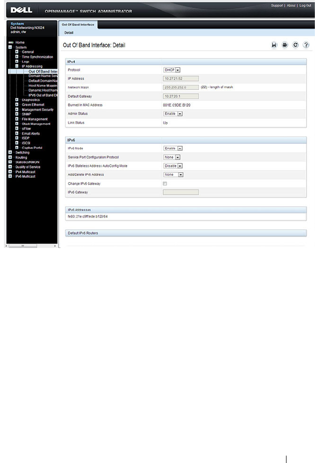
Setting Basic Network Information 153
Figure 7-1. Out of Band Interface
To enable the DHCP client and allow a DHCP server on your network to
automatically assign the network information to the OOB interface, select
DHCP from the Protocol menu. If you statically assign the network
information, make sure the Protocol menu is set to None.
IP Interface Configuration (Default VLAN IP Address)
Use the IP Interface Configuration page to assign the default VLAN IP
address and subnet mask, the default gateway IP address, and to assign the
boot protocol.
To display the IP Interface Configuration page, click Routing
→
IP
→
IP Interface Configuration in the navigation panel.
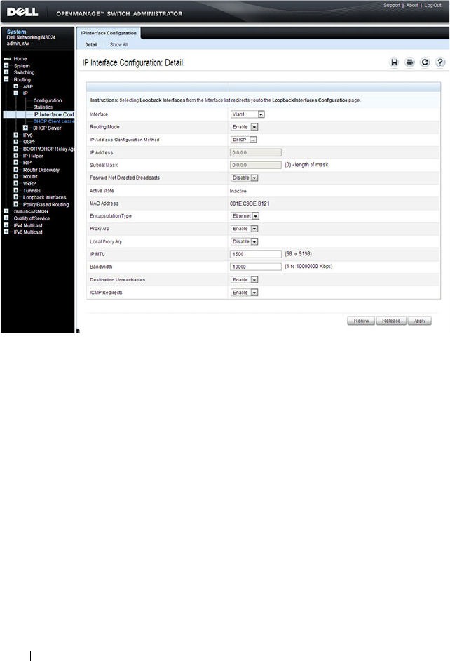
154 Setting Basic Network Information
Figure 7-2. IP Interface Configuration (Default VLAN)
Assigning Network Information to the Default VLAN
To assign an IP Address and subnet mask to the default VLAN:
1
From the
Interface
menu, select VLAN 1.
2
From the
Routing Mode
field, select
Enable
.
3
From the
IP Address Configuration Method
field specify whether to
assign a static IP address (Manual) or use DHCP for automatic address
assignment.
4
If you select
Manual
for the configuration method, specify the I
P Address
and
Subnet Mask
in the appropriate fields.
5
Click
Apply
.
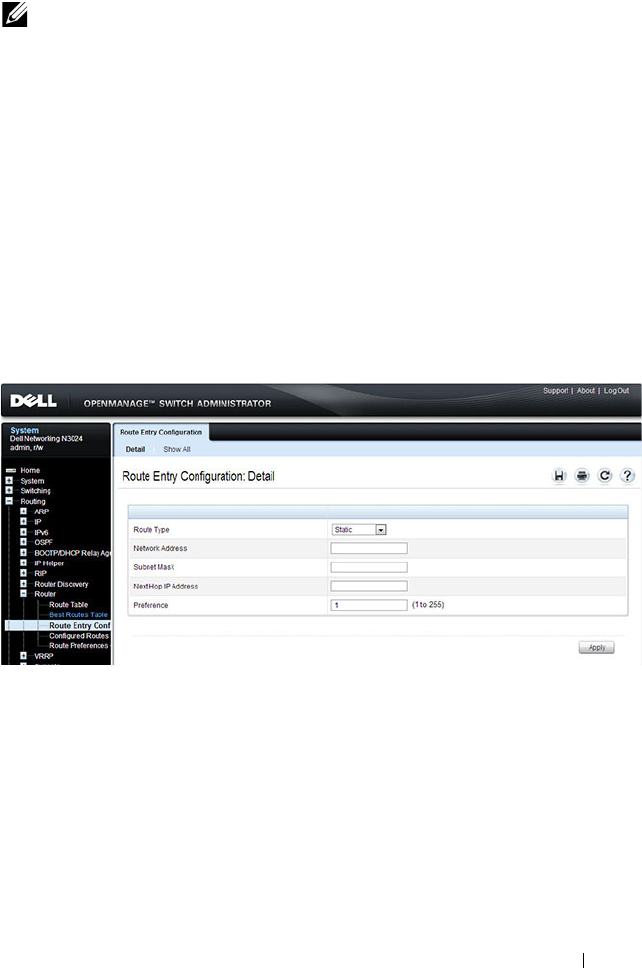
Setting Basic Network Information 155
Route Entry Configuration (Switch Default Gateway)
Use the Route Entry Configuration page to configure the default gateway for
the switch. The default VLAN uses the switch default gateway as its default
gateway. The switch default gateway must not be on the same subnet as the
OOB management port, as the OOB management port cannot route packets
received on the front-panel ports.
To display the Route Entry Configuration page, click Routing
→
Router
→
Route Entry Configuration in the navigation panel.
Figure 7-3. Route Configuration (Default VLAN)
NOTE: You do not need to configure any additional fields on the page. For
information about VLAN routing interfaces, see "Configuring Routing Interfaces"
on page 1021.
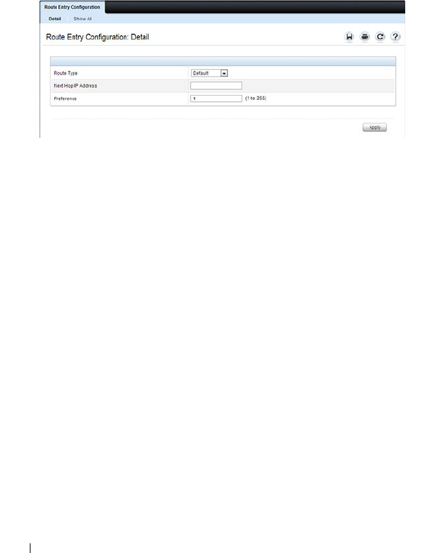
156 Setting Basic Network Information
Configuring a Default Gateway for the Switch:
To configure the switch default gateway:
1
Open the
Route Entry Configuration page.
2
From the
Route Type
field, select Default.
Figure 7-4. Default Route Configuration (Default VLAN)
3
In the
Next Hop IP Address
field, enter the IP address of the default
gateway.
4
Click
Apply
.
For more information about configuring routes, see "Configuring IP Routing"
on page 1063.
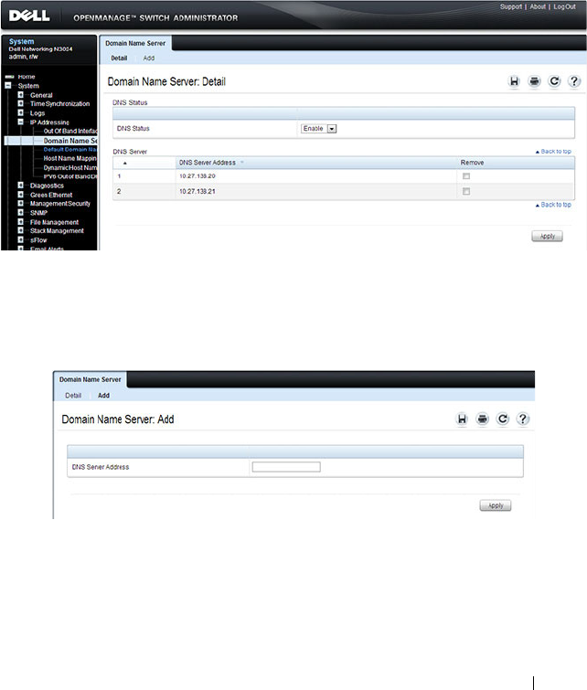
Setting Basic Network Information 157
Domain Name Server
Use the Domain Name Server page to configure the IP address of the DNS
server. The switch uses the DNS server to translate hostnames into IP
addresses.
To display the Domain Name Server page, click System
→
IP Addressing
→
Domain Name Server in the navigation panel.
Figure 7-5. DNS Server
To configure DNS server information, click the Add link and enter the IP
address of the DNS server in the available field.
Figure 7-6. Add DNS Server
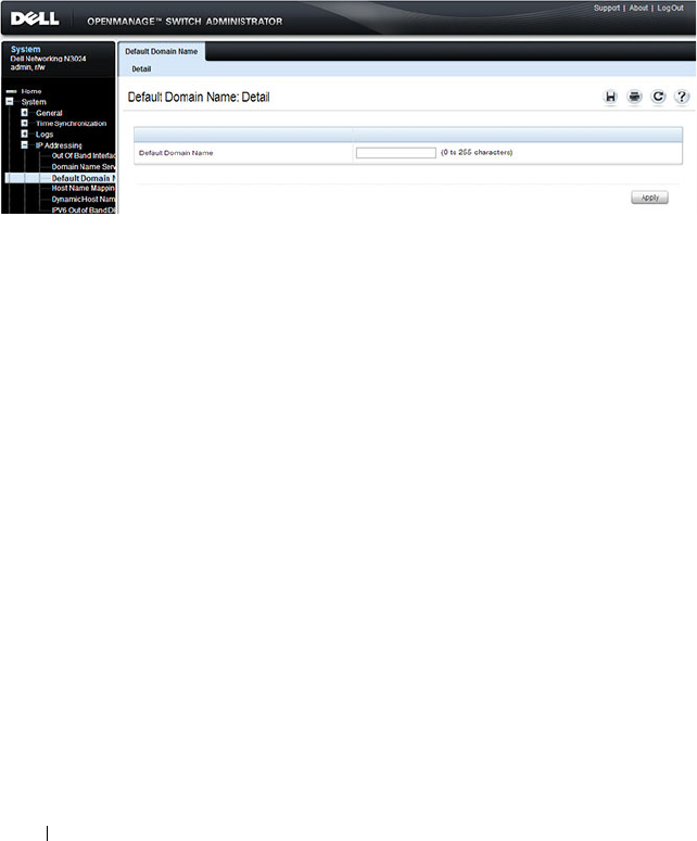
158 Setting Basic Network Information
Default Domain Name
Use the Default Domain Name page to configure the domain name the
switch adds to a local (unqualified) hostname.
To display the Default Domain Name page, click System
→
IP Addressing
→
Default Domain Name in the navigation panel.
Figure 7-7. Default Domain Name
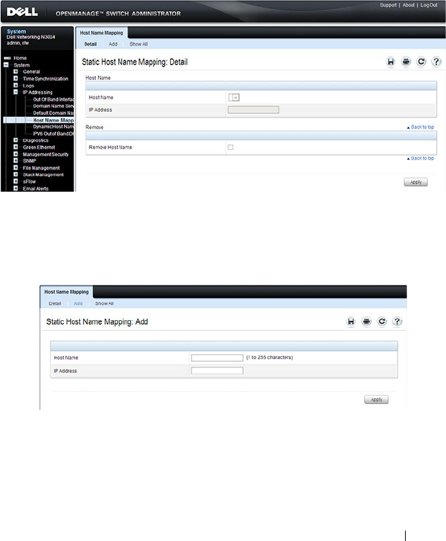
Setting Basic Network Information 159
Host Name Mapping
Use the Host Name Mapping page to assign an IP address to a static host
name. The Host Name Mapping page provides one IP address per host.
To display the Host Name Mapping page, click System
→
IP Addressing
→
Host Name Mapping.
Figure 7-8. Host Name Mapping
To map a host name to an IP address, click the Add link, type the name of the
host and its IP address in the appropriate fields, and then click Apply.
Figure 7-9. Add Static Host Name Mapping
Use the Show All link to view all configured host name-to-IP address
mappings.

160 Setting Basic Network Information
Dynamic Host Name Mapping
Use the Dynamic Host Name Mapping page to view dynamic host entries
the switch has learned. The switch learns hosts dynamically by using the
configured DNS server to resolve a hostname. For example, if you ping
www.dell.com from the CLI, the switch uses the DNS server to lookup the IP
address of dell.com and adds the entry to the Dynamic Host Name Mapping
table.
To display the Dynamic Host Name Mapping page, click System
→
IP
Addressing
→
Dynamic Host Name Mapping in the navigation panel.
Figure 7-10. View Dynamic Host Name Mapping

Setting Basic Network Information 161
Configuring Basic Network Information (CLI)
This section provides information about the commands you use to configure
basic network information on the Dell Networking N2000, N3000, and N4000
series switches. For more information about these commands, see the
Dell
Networking N2000, N3000, and N4000 Series Switches CLI Reference Guide
at support.dell.com/manuals.
Enabling the DHCP Client on the OOB Port
NOTE: N2000 switches do not have an out-of-band interface.
Beginning in Privileged EXEC mode, use the following commands to enable
the DHCP client on the OOB port.
Enabling the DHCP Client on the Default VLAN
Beginning in Privileged EXEC mode, use the following commands to enable
the DHCP client on the default VLAN, which is VLAN 1. As a best practice,
it is recommended that a separate VLAN other than one used for client traffic
be used for in-band management of the switch. In general, using VLAN 1, or
any other VLAN carrying client traffic, for in-band management introduces a
security vulnerability.
Command Purpose
configure Enter Global Configuration mode.
interface out-of-band Enter Interface Configuration mode for the OOB port.
ip address dhcp Enable the DHCP client.
CTRL + Z Exit to Privileged EXEC mode.
show ip interface out-of-
band
Display network information for the OOB port.
Command Purpose
configure Enter Global Configuration mode.
interface vlan 1 Enter Interface Configuration mode for VLAN 1.
ip address dhcp Enable the DHCP client.
ipv6 address dhcp Enable the DHCPv6 client.

162 Setting Basic Network Information
Managing DHCP Leases
Beginning in Privileged EXEC mode, use the following commands to manage
and troubleshoot DHCP leases on the switch.
CTRL + Z Exit to Privileged EXEC mode.
show ip interface vlan 1 Display network information for VLAN 1.
Command Purpose
show dhcp lease
interface [
interface
]
Display IPv4 addresses leased from a DHCP server.
show ipv6 dhcp interface
vlan [
interface
]
Display information about the IPv6 DHCP information
for all interfaces or for the specified interface.
debug dhcp packet Display debug information about DHCPv4 client activities
and to trace DHCPv4 packets to and from the local
DHCPv4 client.
debug ipv6 dhcp Display debug information about DHCPv6 client activities
and to trace DHCPv6 packets to and from the local
DHCPv6 client.
ipv6 address
{[
prefix/prefixlien
] |
autoconfig | dhcp}
Set the IPv6 address of the management interface or
enables autoconfiguration or DHCP.
ipv6 gateway
ipv6-
address
Set the IPv6 default gateway address.
ipv6 enable Enable IPv6 functionality on the interface.
show ipv6 interface out-
of-band
Show settings for the interface.
Command Purpose

Setting Basic Network Information 163
Configuring Static Network Information on the OOB Port
NOTE: N2000 switches do not have an out-of-band interface.
Beginning in Privileged EXEC mode, use the following commands to
configure a static IP address, subnet mask, and default gateway on the OOB
port. If no default gateway is configured, then the zero subnet (0.0.0.0) is
used. In this configuration, the OOB port can reach hosts in the local subnet
only, because the OOB port will not be able to issue ARP requests to the
default gateway. Configuring a default gateway address on the OOB port
allows the OOB port to issue ARPs and address traffic to hosts on other
subnets. The OOB port subnet may not overlap with any in-band VLAN
subnet.
NOTE: The out-of-band port also supports IPv6 address assignment, including IPv6
auto-configuration and an IPv6 DHCP client.
Configuring Static Network Information on the Default VLAN
Beginning in Privileged EXEC mode, use the following commands to
configure a static IP address, subnet mask, and default gateway on the default
VLAN. Alternatively, a DHCP server may be used to obtain a network address.
The switch also supports IPv6 address auto-configuration.
Command Purpose
configure Enter Global Configuration mode.
interface out-of-band Enter Interface Configuration mode for the OOB
port.
ip address
ip_address
subnet_mask
[
gateway_ip
]
Configure a static IP address and subnet mask.
Optionally, you can also configure a default gateway.
ipv6 address
prefix/prefix-
length
Configure an IPv6 prefix for the OOB port
ipv6 address enable Enable IPv6 addressing on the OOB port
ipv6 address autoconfig Enable IPv6 auto-configuration for the OOB port
ipv6 address dhcp Enable DHCP address assignment for the OOB port.
CTRL + Z Exit to Privileged EXEC mode.
show ip interface out-of-band Verify the network information for the OOB port.

164 Setting Basic Network Information
Static IP subnets on inband ports (configured on switch VLANs) may not
overlap with the OOB port subnet. If configuring management access on the
front-panel ports, it is recomended that:
• A VLAN other than the default VLAN be used to avoid attack vectors
enabled by incorrect cabling.
• Both ACLs and Management ACLs be utilized to reduce the possibility of
DoS attacks or intruders gaining access to the switch management
console. The advantage of the management ACL is that it can also protect
the OOB port, whereas ACLs can only protect access via an in-band port.
Configuring and Viewing Additional Network Information
Beginning in Privileged EXEC mode, use the following commands to
configure a DNS server, the default domain name, and a static host name-to-
address entry. Use the show commands to verify configured information and
to view dynamic host name mappings.
Command Purpose
configure Enter Global Configuration mode.
interface vlan 1 Enter Interface Configuration mode for VLAN 1.
ip address
ip_address
subnet_mask
Enter the IP address and subnet mask.
ipv6 address
prefix/prefix-length
[eui64]
Enter the IPv6 address and prefix.
ipv6 enable Enable IPv6 on the interface.
exit Exit to Global Configuration mode
ip default-gateway
ip_address
Configure the default gateway.ipv6 gateway
Configure the default gateway for IPv6.
ipv6 gateway
ip_address
Configure the default gateway for IPv6.
exit Exit to Privileged Exec mode.
show ip interface vlan 1 Verify the network information for VLAN 1.
show ipv6 interface vlan 1 Verify IPv6 network information for VLAN 1.

Setting Basic Network Information 165
Command Purpose
configure Enter Global Configuration mode.
ip domain-lookup Enable IP DNS-based host name-to-address translation.
ip name-server
ip_address
Enter the IP address of an available name server to use to
resolve host names and IP addresses.
You can specify up to six DNS servers. The first server you
configure is the primary DNS server.
ip domain-name
name
Define a default domain name to complete unqualified
host names.
ip host
name ip_address
Use to configure static host name-to-address mapping in
the host cache.
ip address-conflict-
detect run
Trigger the switch to run active address conflict detection
by sending gratuitous ARP packets for IPv4 addresses on
the switch.
CTRL + Z Exit to Privileged EXEC mode.
show ip interface vlan 1 Verify the network information for VLAN 1.
show hosts Verify the configured network information and view the
dynamic host mappings.
show ip address-conflict View the status information corresponding to the last
detected address conflict.
clear ip address-conflict-
detect
Clear the address conflict detection status in the switch.

166 Setting Basic Network Information
Basic Network Information Configuration
Example
In this example, an administrator at a Dell office in California decides not to
use the Dell Easy Setup Wizard to perform the initial switch configuration.
The administrator configures a Dell Networking N2000, N3000, and N4000
series switches to obtain its information from a DHCP server on the
management network and creates the administrative user with read/write
access. The administrator also configures the following information:
• Primary DNS server: 10.27.138.20
• Secondary DNS server: 10.27.138.21
• Default domain name: sunny.dell.com
The administrator also maps the administrative laptop host name to its IP
address. The administrator uses the OOB port to manage the switch.
To configure the switch:
1
Connect the OOB port to the management network. DHCP is enabled by
on the switch OOB interface by default on N3000 and N4000 switches.
DHCP is enabled on VLAN 1 on the N2000 switches. If the DHCP client
on the switch has been disabled, use the following commands to enable
the DHCP client on the OOB port.
console#configure
console(config)#interface out-of-band
console(config-if)#ip address dhcp
console(config-if)#exit
2
Configure the administrative user.
console(config)#username admin password secret123
level 15
3
Configure the DNS servers, default domain name, and static host
mapping.
console(config)#ip name-server 10.27.138.20
10.27.138.21
console(config)#ip domain-name sunny.dell.com
console(config)#ip host admin-laptop 10.27.65.103
console(config)#exit

Setting Basic Network Information 167
4
View the network information that the DHCP server on the network
dynamically assigned to the switch.
console#show ip interface out-of-band
IP Address........................ 10.27.22.153
Subnet Mask...................... 255.255.255.0
Default Gateway.................. 10.27.22.1
Protocol Current................. DHCP
Burned In MAC Address............ 001E.C9AA.AA08
5
View additional network information.
console#show hosts
Host name:
Default domain: sunny.dell.com dell.com
Name/address lookup is enabled
Name servers (Preference order): 10.27.138.20,
10.27.138.21
Configured host name-to-address mapping:
Host Addresses
----------- ------------------------------------
admin-laptop 10.27.65.103
cache: TTL (Hours)
Host Total Elapsed Type Addresses
--------- ------- ------- --------- ---------
No hostname is mapped to an IP address
6
Verify that the static hostname is correctly mapped.
console#ping admin-laptop
Pinging admin-laptop with 0 bytes of data:
Reply From 10.27.65.103: icmp_seq = 0. time <10
msec.
Reply From 10.27.65.103: icmp_seq = 1. time <10
msec.

168 Setting Basic Network Information

Managing QSFP Ports 169
8
Managing QSFP Ports
QSFP ports available on N4000 series switches can operate in 1 x 40G mode
or in 4 x 10G mode. Appropriate cables must be used that match the selected
mode. When changing from one mode to another, a switch reboot is required.
The QSFP ports also support stacking over the interfaces in either 1 x 40G or
4 x 10G mode. Changing from Ethernet mode to stacking mode and vice-
versa requires a reboot as well.
The ports on a QSFP plugin module are named Fo1/1/1-2 in 40-gigabit mode
and Te1/1/1-8 in 10-gigabit mode. On the N4064, the fixed QSFP ports are
named Fo1/0/1-2 in 40-gigabit mode and Te1/0/49-56 in 10-gigabit mode. All
of the possible populated or configured interfaces will show in the show
interfaces status command regardless of the port mode, i.e. 40-gigabit or
10-gigabit. Unpopulated or unconfigured interfaces for plug in modules do
not show in the show interfaces status command.
The default setting for a 40-gigabit Ethernet interface is nonstacking,
40-gigabit Ethernet (1 x 40G).
The commands to change 1 x 40G and 4 x 10G modes are always entered on
the 40-gigabit interfaces.
The commands to change the Ethernet/stack mode are entered on the
appropriate interface (tengigabitethernet or fortygigabitethernet). It is
possible to configure some of the 10G ports in a 40G interface as stacking and
not others.
To reconfigure a QSFP port, select the 40-gigabit port to change in Interface
Config mode and enter the hardware profile portmode command with the
selected mode. For example, to change a 1 x 40G port to 4 x 10G mode, enter
the following commands on the forty-gigabit interface:
console(config)#interface fo1/1/1
console(config-if-Fo1/1/2)#hardware profile portmode 4x10g
This command will not take effect until the switch is rebooted.
console(config-if-Fo1/1/2)#do reload
Are you sure you want to reload the stack? (y/n)

170 Managing QSFP Ports
To change a 4 x 10G port to 1 x 40G mode, enter the following commands on
the 40-gigabit interface:
console(config)#interface Fo2/1/1
console(config-if-Fo2/1/1)#hardware profile portmode 1x40g
This command will not take effect until the switch is rebooted.
console(config-if-Fo1/1/2)#do reload
Are you sure you want to reload the stack? (y/n)
Attempting to change the port mode on the tengigabit interface will give the
error “An invalid interface has been used for this function.”

Managing a Switch Stack 171
9
Managing a Switch Stack
This chapter describes how to configure and manage a stack of switches.
The topics covered in this chapter include:
• Stacking Overview
• Default Stacking Values
• Managing and Monitoring the Stack (Web)
• Managing the Stack (CLI)
• Stacking and NSF Usage Scenarios
Stacking Overview
The Dell Networking N2000, N3000, and N4000 and series switches include a
stacking feature that allows up to 12 switches to operate as a single unit. The
N2000 and N3000 series switches have two fixed mini-SAS stacking
connectors at the rear. N2000 series switches will stack with other N2000
series switches and Dell Networking 3000 series switches stack with other
3000 series switches.
Dell Networking 4000 series switches stack with other Dell Networking 4000
series switches over front panel ports configured for stacking.
A stack of twelve 48-port N2000 or N3000 switches has an aggregate
throughput capacity of 576 Gigabits. Dell Networking N2000/N3000 stacking
links operate at 21 Gbps or 4.3% of total aggregate throughput capacity of a
full stack; therefore, it is recommended that operators provision large stacking
topologies such that it is unlikely that a significant portion of the stack
capacity will transit stacking links. One technique for achieving this is to
distribute uplinks evenly across the stack vs. connecting all uplinks to a single
stack unit or to adjacent stacking units.
Dell Networking N4000 series switches support high performance stacking
over front panel ports, allowing increased capacity to be added as needed,
without affecting network performance and providing a single point of
management. Up to twelve Dell Networking N4000 series switches can be

172 Managing a Switch Stack
stacked using any port as long as the link bandwidth for parallel stacking links
is the same. In other words, all the port types on the N4000 series switches
can be used for stacking. Additional stacking connections can be made
between adjacent switch units to increase the stacking bandwidth provided
that all redundant stacking links have the same port speed. It is strongly
recommended that the stacking bandwidth be kept equal across all stacking
connections; that is, avoid mixing single and double stacking connections
within a stack. Up to eight redundant stacking links operating at the same
speed can be configured on an N4000 stack unit (four in each direction).
A stack of twelve N4000 series switches has an aggregate front panel capacity
of 5.760 terabits (not including the 40G ports). Provisioning for 5% inter-
stack capacity requires 280 gigabits of bandwidth dedicated to stacking or all
four 40G ports plus another twelve 10G ports. Therefore, it is recommended
that operators provision large stacking topologies such that it is unlikely that a
significant portion of the stack capacity will transit stacking links. One
technique for achieving this is to distribute downlinks and transit links evenly
across the stack vs. connecting all downlinks/transit links to a single stack unit
or to adjacent stacking units.
If Priority Flow Control (PFC) is enabled on any port in an N4000 series
stack, stacking is supported at distances up to 100 meters on the stacking
ports. If PFC is not enabled, stacking is supported up to the maximum
distance supported by the transceiver on the stack links. Note that PFC
cannot be enabled on stacking ports — the system handles the buffering and
flow control automatically.
A single switch in the stack manages all the units in the stack (the stack
master), and you manage the stack by using a single IP address. The IP
address of the stack does not change, even if the stack master changes.
A stack is created by daisy-chaining stacking links on adjacent units. If
available, up to eight links per stack unit can be used for stacking (four in
each direction). A stack of units is manageable as a single entity when the
units are connected together. If a unit cannot detect a stacking partner on any
port enabled for stacking, the unit automatically operates as a standalone
unit. If a stacking partner is detected, the switch always operates in stacking
mode. One unit in the stack is designated as the stack master. The master
manages all the units in the stack. The stack master runs the user interface

Managing a Switch Stack 173
and switch software, and propagates changes to the member units. To manage
a stack using the serial interface, you must connect to the stack master via the
connect command or by physically connecting the cable to the stack master.
A second switch is designated as the standby unit, which becomes the master
if the stack master is unavailable. You can manually configure which unit is
selected as the standby, or the system can select the standby automatically.
When units are in a stack, the following activities occur:
• All units are checked for software version consistency.
• The switch Control Plane is active only on the master. The Control Plane
is a software layer that manages system and hardware configuration and
runs the network control protocols to set system configuration and state.
• The switch Data Plane is active on all units in the stack, including the
master. The Data Plane is the set of hardware components that forward
data packets without intervention from a control CPU.
• The running configuration is propagated to all units and the application
state is synchronized between the master and standby during normal
stacking operation. The startup configuration and backup configuration
on the stack members are not overwritten with the master switch
configuration.
Dell strongly recommends connecting the stack in a ring topology so that
each switch is connected to two other switches.
Connecting switches in a ring topology allows the stack to utilize the
redundant communication path to each switch. If a switch in a ring topology
fails, the stack can automatically establish a new communications path to the
other switches. Switches not stacked in a ring topology may split into multiple
independent stacks upon the failure of a single switch or stacking link.
Additional stacking connections can be made between adjacent switch units
to increase the stacking bandwidth, provided that all redundant stacking links
have the same bandwidth. It is strongly recommended that the stacking
bandwidth be kept equal across of all stacking connections; that is, avoid
mixing single and double stacking connections within a stack. Up to eight
redundant stacking links can be configured on a stacking unit (four in each
direction).
Figure 9-1 shows a stack with three switches as stack members connected in a
ring topology.
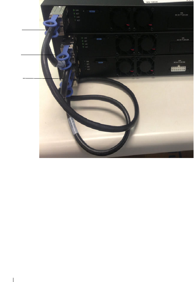
174 Managing a Switch Stack
Figure 9-1. Connecting a Stack of Switches
The stack in Figure 9-1 has the following physical connections between the
switches:
• The lower stacking port on Unit 1 is connected to the upper stacking port
on Unit 2.
• The lower stacking port on Unit 2 is connected to the upper stacking port
on Unit 3.
• The lower stacing port on Unit 3 is connected to the upper stacking port
on Unit 1.
Dell Networking N2000, N3000, and N4000 Stacking Compatibility
Dell Networking N2000, N3000, and N4000 series switches do not stack with
different Dell Networking series switches or Dell PowerConnect series
switches. Dell Networking N2000 series switches only stack with other N2000
Unit 1
Unit 2
Unit 3

Managing a Switch Stack 175
series switches. Likewise, Dell Networking N3000 series switches only stack
with other Dell N3000 series switches. Dell Networking N4000 series switches
stack with other Dell Networking N4000 series switches.
How is the Stack Master Selected?
A stack master is elected or re-elected based on the following considerations,
in order:
1
The switch is currently the stack master.
2
The switch has the higher MAC address.
3
A unit is selected as standby by the administrator, and a fail over action is
manually initiated or occurs due to stack master failure.
In most cases, a switch that is added to an existing stack will become a stack
member, and not the stack master. When you add a switch to the stack, one
of the following scenarios takes place regarding the management status of the
new switch:
• If the switch has the stack master function enabled but another stack
master is already active, then the switch changes its configured stack
master value to disabled.
• If the stack master function is unassigned and there is another stack
master in the system then the switch changes its configured stack master
value to disabled.
• If the stack master function is enabled or unassigned and there is no other
stack master in the system, then the switch becomes stack master.
• If the stack master function is disabled, the unit remains a non-stack
master.
If the entire stack is powered OFF and ON again, the unit that was the
stack
master
before the reboot will remain the
stack master
after the stack resumes
operation.
You can manually set the unit number for the switch. To avoid unit-number
conflicts, one of the following scenarios takes place when you add a new
member to the stack:
• If the switch has a unit number that is already in use, then the unit that
you add to the stack changes its configured unit number to the lowest
unassigned unit number.

176 Managing a Switch Stack
• If the switch you add does not have an assigned unit number, then the
switch sets its configured unit number to the lowest unassigned unit
number.
• If the unit number is configured and there are no other devices using the
unit number, then the switch starts using the configured unit number.
• If the switch detects that the maximum number of units already exist in
the stack making it unable to assign a unit number, then the switch sets its
unit number to
unassigned
and does not participate in the stack.
Adding a Switch to the Stack
When adding a new member to a stack, make sure that only the stack cables,
and no network cables, are connected before powering up the new unit. Stack
port configuration is stored on the member units. If stacking over Ethernet
ports (N4000 only), configure the ports on the unit to be added to the stack as
stacking ports and power the unit off prior to connecting the stacking cables.
Make sure the links are not already connected to any ports of that unit. This is
important because if STP is enabled and any links are UP, the STP
reconvergence will take place as soon as the link is detected.
After the stack cables on the new member are connected to the stack, you can
power up the new units, beginning with the unit directly attached to the
currently powered-up unit. Always power up new stack units closest to an
existing powered unit first. Do not connect a new member to the stack after it
is powered up. Also, do not connect two functional, powered-up stacks
together. Hot insertion of units into a stack is not supported.
If a new switch is added to a stack of switches that are powered and running
and already have an elected stack master, the newly added switch becomes a
stack member rather than the stack master. Use the boot auto-copy-sw
command on the stack master to enable automatic firmware upgrade of newly
added switches. If a firmware mismatch is detected, the newly added switch
does not fully join the stack and holds until it is upgraded to the same
firmware version as the master switch. After firmware synchronization
finishes, the running configuration of the newly added unit is overwritten
with the stack master configuration. Stack port configuration is always stored
on the local unit and may be updated with preconfiguration information from
the stack master when the unit joins the stack.

Managing a Switch Stack 177
You can preconfigure information about a stack member and its ports before
you add it to the stack. The preconfiguration takes place on the stack master.
If there is saved configuration information on the stack master for the newly
added unit, the stack master applies the configuration to the new unit;
otherwise, the stack master applies the default configuration to the new unit.
Removing a Switch from the Stack
Prior to removing a member from a stack, check that other members of the
stack will not become isolated from the stack due to the removal. Check the
stack-port error counters to ensure that a stack configured in a ring topology
can establish a communication path around the member to be removed.
The main point to remember when you remove a unit from the stack is to
disconnect all the links on the stack member to be removed. Also, be sure to
take the following actions:
• Remove all the STP participating ports and wait to stabilize the STP.
• Remove all the member ports of any Port-Channels (LAGs) so there will
not be any control traffic destined to those ports connected to this member.
• Statically re-route any traffic going through this unit.
When a unit in the stack fails, the stack master removes the failed unit from
the stack. The failed unit reboots with its original running-config. If the stack
is configured in a ring topology, then the stack automatically routes around
the failed unit. If the stack is not configured in a ring topology, then the stack
may split, and the isolated members will reboot and re-elect a new stack
master. No changes or configuration are applied to the other stack members;
however, the dynamic protocols will try to reconverge as the topology could
change because of the failed unit.
If you remove a unit and plan to renumber the stack, issue a no member
unit
command in Stack Configuration mode to delete the removed switch from
the configured stack member information.
How is the Firmware Updated on the Stack?
When you add a new switch to a stack, the Stack Firmware Synchronization
feature automatically synchronizes the firmware version with the version
running on the stack master per the configuration on the master switch. The
synchronization operation may result in either upgrade or downgrade of
firmware on the mismatched stack member.

178 Managing a Switch Stack
Upgrading the firmware on a stack of switches is the same as upgrading the
firmware on a single switch. After you download a new image by using the File
Download page or copy command, the downloaded image is distributed to all
the connected units of the stack. For more information about downloading
and installing images, see "Managing Images and Files" on page 359.
What is Stacking Standby?
A standby unit is preconfigured in the stack. If the current stack master fails,
the standby unit becomes the stack master. If no switch is pre-configured as
the standby unit, the software automatically selects a standby unit from the
existing stack units.
When the failed master resumes normal operation, it joins the stack as a
member (not a master) if the new stack master has already been elected.
The stack master copies its running configuration to the standby unit
whenever it changes (subject to some restrictions to reduce overhead). This
enables the standby unit to take over the stack operation with minimal
interruption if the stack master becomes unavailable.
Operational state synchronization also occurs:
• when you save the running configuration to the startup configuration on
the stack master.
• when the backup unit changes.
What is Nonstop Forwarding?
Networking devices, such as the Dell Networking series switches, are often
described in terms of three semi-independent functions called the forwarding
plane, the control plane, and the management plane. The forwarding plane
forwards data packets and is implemented in hardware. The control plane is
the set of protocols that determine how the forwarding plane should forward
packets, deciding which data packets are allowed to be forwarded and where
they should go. Application software on the stack master acts as the control
plane. The management plane is application software running on the stack
master that provides interfaces allowing a network administrator to configure
the device.
The Nonstop Forwarding (NSF) feature allows the forwarding plane of stack
units to continue to forward packets while the control and management
planes restart as a result of a power failure, hardware failure, or software fault

Managing a Switch Stack 179
on the stack master. This type of operation is called nonstop forwarding.
When the stack master fails, only the switch ASICs on the stack master need
to be restarted.
To prevent adjacent networking devices from rerouting traffic around the
restarting device, the NSF feature uses the following three techniques:
1
A protocol can distribute a part of its control plane to stack units so that
the protocol can give the appearance that it is still functional during the
restart.
2
A protocol may enlist the cooperation of its neighbors through a technique
known as graceful restart.
3
A protocol may simply restart after the failover if neighbors react slowly
enough that they will not normally detect the outage.
The NSF feature enables the stack master unit to synchronize the running-
config within 60 seconds after a configuration change has been made.
However, if a lot of configuration changes happen concurrently, NSF uses a
back-off mechanism to reduce the load on the switch. The show nsf
command output includes information about when the next running-config
synchronization will occur.
Initiating a Failover
The NSF feature allows you to initiate a failover using the initiate failover
command, which causes the former stack master to reboot (cold start), and
the new master to perform a warm restart.
Initiating a failover reloads the stack master, triggering the backup unit to
take over. Before the failover, the stack master pushes application data and
other important information to the backup unit. Although the handoff is
controlled and causes minimal network disruption, some application state is
lost, such as pending timers and other pending internal events.
Checkpointing
Switch applications (features) that build up a list of data such as neighbors or
clients can significantly improve their restart behavior by remembering this
data across a warm restart. This data can either be stored persistently, as
DHCP server and DHCP snooping store their bindings database, or the stack
master can checkpoint this data directly to the standby unit. Persistent

180 Managing a Switch Stack
storage allows an application on a standalone unit to retain its data across a
restart, but since the amount of storage is limited, persistent storage is not
always practical.
The NSF checkpoint service allows the stack master to communicate certain
data to the backup unit in the stack. When the stack selects a backup unit,
the checkpoint service notifies applications to start a complete checkpoint.
After the initial checkpoint is done, applications checkpoint changes to their
data.
Table 9-1 lists the applications on the switch that checkpoint data and
describes the type of data that is checkpointed.
NOTE: The switch cannot guarantee that a backup unit has exactly the same data
that the stack master has when it fails. For example, the stack master might fail
before the checkpoint service gets data to the backup if an event occurs shortly
before a failover.
Table 9-1. Applications that Checkpoint Data
Application Checkpointed Data
ARP Dynamic ARP entries
Auto VOIP Calls in progress
Captive Portal Authenticated clients
DHCP server Address bindings (persistent)
DHCP snooping DHCP bindings database
DOT1Q Internal VLAN assignments
DOT1S Spanning tree port roles, port states, root bridge, etc.
DOT1X Authenticated clients
DOT3ad Port states
IGMP/MLD Snooping Multicast groups, list of router ports, last query data for
each VLAN
IPv6 NDP Neighbor cache entries
iSCSI Connections
LLDP List of interfaces with MED devices attached

Managing a Switch Stack 181
Switch Stack MAC Addressing and Stack Design Considerations
The switch stack uses the MAC addresses assigned to the stack master.
If the backup unit assumes control due to a stack master failure or warm
restart, the backup unit continues to use the original stack master’s MAC
addresses. This reduces the amount of disruption to the network because
ARP and other L2 entries in neighbor tables remain valid after the failover to
the backup unit.
Stack units should always be connected with a ring topology (or other
biconnected topology), so that the loss of a single stack link does not divide
the stack into multiple stacks. If a stack is partitioned such that some units
lose all connectivity to other units, then both parts of the stack start using the
same MAC addresses. This can cause severe problems in the network.
If you move the stack master to a different place in the network, make sure
you power down the whole stack before you redeploy the stack master so that
the stack members do not continue to use the MAC address of the redeployed
switch.
NSF Network Design Considerations
You can design your network to take maximum advantage of NSF. For
example, by distributing a LAG's member ports across multiple units, the
stack can quickly switch traffic from a port on a failed unit to a port on a
OSPFv2 Neighbors and designated routers
OSPFv3 Neighbors and designated routers
Route Table Manager IPv4 and IPv6 dynamic routes
SIM The system's MAC addresses. System up time. IP address,
network mask, default gateway on each management
interface, DHCPv6 acquired IPv6 address.
Voice VLAN VoIP phones identified by CDP or DHCP (not LLDP)
NOTE: Each switch is assigned four consecutive MAC addresses. A stack of
switches uses the MAC addresses assigned to the stack master.
Table 9-1. Applications that Checkpoint Data
Application Checkpointed Data

182 Managing a Switch Stack
surviving unit. When a unit fails, the forwarding plane of surviving units
removes LAG members on the failed unit so that it only forwards traffic onto
LAG members that remain up. If a LAG is left with no active members, the
LAG goes down. To prevent a LAG from going down, configure LAGs with
members on multiple units within the stack, when possible. If a stack unit
fails, the system can continue to forward on the remaining members of the
stack.
If your switch stack performs VLAN routing, another way to take advantage of
NSF is to configure multiple “best paths” to the same destination on
different stack members. If a unit fails, the forwarding plane removes Equal
Cost Multipath (ECMP) next hops on the failed unit from all unicast
forwarding table entries. If the cleanup leaves a route without any next hops,
the route is deleted. The forwarding plane only selects ECMP next hops on
surviving units. For this reason, try to distribute links providing ECMP paths
across multiple stack units.
Why is Stacking Needed?
Stacking increases port count without requiring additional configuration. If
you have multiple Dell Networking switches, stacking them helps make
management of the switches easier because you configure the stack as a single
unit and do not need to configure individual switches.
Default Stacking Values
Stacking is always enabled on Dell Networking series switches.
On the N4000 switches, by default, the 10G SFP+ ports are in Ethernet
mode and must be configured to be used as stacking ports. Ports that are
configured in stacking mode show as “detached” in the output of the show
interfaces status command.
Configuring an Ethernet port as a stacking port changes the default
configuration of the port. The port stacking configuration does not show in
the running-config. To determine the stacking configuration of a port, use the
show switch stack-ports command. On the N2000/N3000 switches, there are

Managing a Switch Stack 183
two fixed stacking ports in the rear of the switch. Stacking on Ethernet ports
is not supported. The fixed stacking ports show as TwentygigabitStacking and
are abbreviated Tw.
NSF is enabled by default. You can disable NSF to redirect the CPU resources
consumed by data checkpointing. Checkpointing only occurs when a backup
unit is elected, so there is no need to disable the NSF feature on a standalone
switch. When a new unit is added to the stack, the new unit takes the
configuration of the stack, including the NSF setting. OSPF implements a
separate graceful restart control that enables NSF for OSPF. OSPF graceful
restart is not enabled by default.
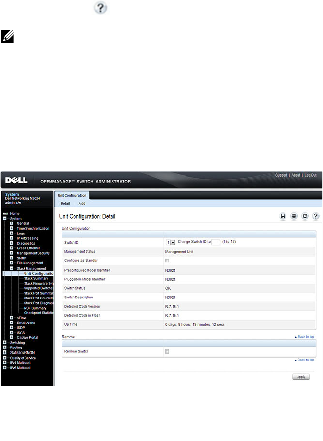
184 Managing a Switch Stack
Managing and Monitoring the Stack (Web)
This section provides information about the OpenManage Switch
Administrator pages for configuring and monitoring stacking on a Dell
Networking N2000, N3000, and N4000 series switches. For details about the
fields on a page, click at the top of the page.
Unit Configuration
Use the Unit Configuration page to change the unit number and unit type
(Management, Member, or Standby).
To display the Unit Configuration page, click System → Stack Management
→ Unit Configuration in the navigation panel.
Figure 9-2. Stack Unit Configuration
NOTE: The changes you make to the Stacking configuration pages take effect only
after the device is reset.
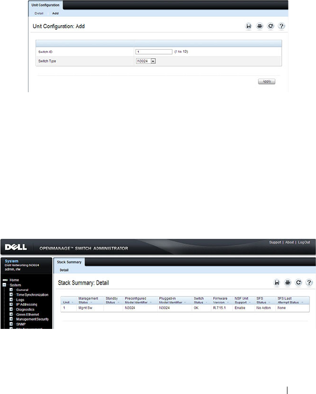
Managing a Switch Stack 185
Changing the ID or Switch Type for a Stack Member
To change the switch ID or type:
1
Open the
Unit Configuration
page.
2
Click
Add
to display the
Add Unit
page.
Figure 9-3. Add Remote Log Server Settings
3
Specify the switch ID, and select the model number of the switch.
4
Click
Apply
.
Stack Summary
Use the Stack Summary page to view a summary of switches participating in
the stack.
To display the Stack Summary page, click System
→
Stack Management
→
Stack Summary in the navigation panel.
Figure 9-4. Stack Summary

186 Managing a Switch Stack
Stack Firmware Synchronization
Use the Stack Firmware Synchronization page to control whether the
firmware image on a new stack member can be automatically upgraded or
downgraded to match the firmware image of the stack master.
To display the Stack Firmware Synchronization page, click System
→
Stack
Management
→
Stack Firmware Synchronization in the navigation panel.
Figure 9-5. Stack Firmware Synchronization
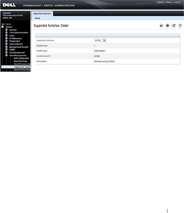
Managing a Switch Stack 187
Supported Switches
Use the Supported Switches page to view information regarding each type of
supported switch for stacking, and information regarding the supported
switches.
To display the Supported Switches page, click System
→
Stack Management
→
Supported Switches in the navigation panel.
Figure 9-6. Supported Switches

188 Managing a Switch Stack
Stack Port Summary
Use the Stack Port Summary page to configure the stack-port mode and to
view information about the stackable ports. This screen displays the unit, the
stackable interface, the configured mode of the interface, the running mode
as well as the link status and link speed of the stackable port.
To display the Stack Port Summary page, click System
→
Stack Management
→
Stack Port Summary in the navigation panel.
Figure 9-7. Stack Port Summary
NOTE: By default the ports are configured to operate as Ethernet ports. To
configure a port as a stack port, you must change the Configured Stack Mode
setting from Ethernet to Stack.
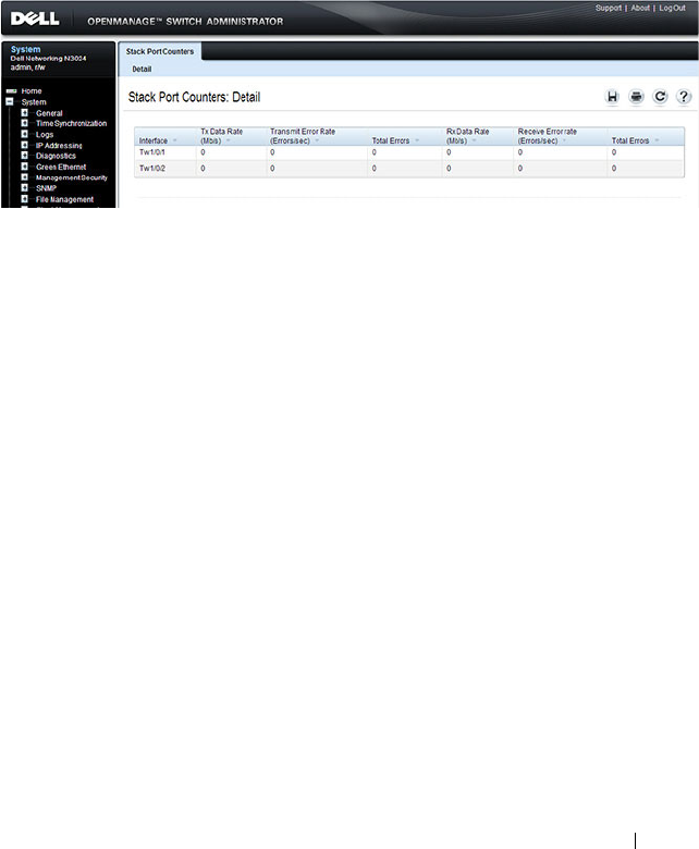
Managing a Switch Stack 189
Stack Port Counters
Use the Stack Port Counters page to view the transmitted and received
statistics, including data rate and error rate.
To display the Stack Port Counters page, click System
→
Stack Management
→
Stack Point Counters in the navigation panel.
Figure 9-8. Stack Port Counters
Stack Port Diagnostics
The Stack Port Diagnostics page is intended for Field Application Engineers
(FAEs) and developers only.
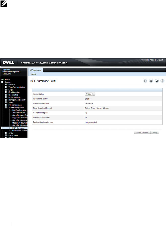
190 Managing a Switch Stack
NSF Summary
Use the NSF Summary page to change the administrative status of the NSF
feature and to view NSF information.
To display the NSF Summary page, click System → Stack Management →
NSF Summary in the navigation panel.
Figure 9-9. NSF Summary
To cause the maser unit to failover to the standby unit, click Initiate Failover.
The failover results in a warm restart of the stack master. Initiating a failover
reloads the stack master, triggering the backup unit to take over.
NOTE: The OSPF feature uses NSF to enable the hardware to continue forwarding
IPv4 packets using OSPF routes while a backup unit takes over stack master
responsibility. To configure NSF on a stack that uses OSPF or OSPFv3, see "NSF
OSPF Configuration" on page 1137 and "NSF OSPFv3 Configuration" on page 1154.
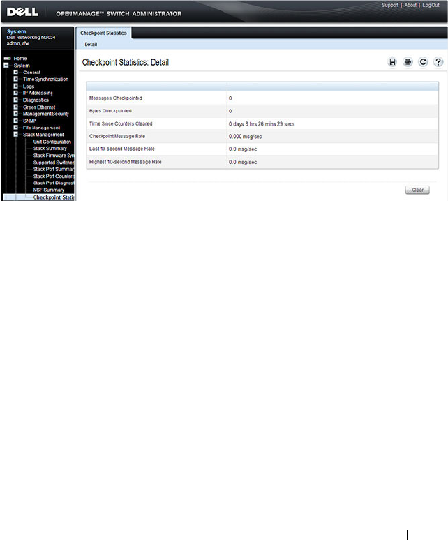
Managing a Switch Stack 191
Checkpoint Statistics
Use the Checkpoint Statistics page to view information about checkpoint
messages generated by the stack master.
To display the Checkpoint Statistics page, click System → Stack
Management → Checkpoint Statistics in the navigation panel.
Figure 9-10. Checkpoint Statistics

192 Managing a Switch Stack
Managing the Stack (CLI)
This section provides information about the commands you use to manage
the stack and view information about the switch stack. For more information
about these commands, see the
Dell Networking N2000, N3000, and N4000
Series Switches CLI Reference Guide
at support.dell.com/manuals.
Configuring Stack Member, Stack Port, and NSF Settings
Beginning in Privileged EXEC mode, use the following commands to
configure stacking and NSF settings.
Command Purpose
configure Enter Global Configuration mode.
switch
current_ID
renumber
new_ID
Change the switch ID number. The valid range is 1-10.
NOTE: Changing the ID number causes all switches in the
stack to be reset to perform stack master renumbering. The
running configuration is cleared when the units reset.
stack Enter Global Stack Configuration mode.
initiate failover Move the management switch functionality from the
master switch to the standby switch.
standby
unit
Specify the stack member that will come up as the master
if a stack failover occurs.
set description
unit
Configure a description for the specified stack member.

Managing a Switch Stack 193
member
unit
SID
Add a switch to the stack and specify the model of the new
stack member.
•
unit
- The switch unit ID
•
SID
- The index into the database of the supported
switch types, indicating the type of the switch being
preconfigured.
Note
: Member configuration displayed in the running
config may be learned from the physical stack. Member
configuration is not automatically saved in the startup-
config. Save the configuration to retain the current
member settings.
To view the SID associated with the supported switch
types, use the
show supported switchtype
command in
Privileged EXEC mode.
stack-port
tengigabitethernet
unit/slot/port
{ethernet |
stack}
Set the mode of the port to either Ethernet or stacking
(N4000 only).
nsf Enable nonstop forwarding on the stack.
exit Exit to Global Config mode.
boot auto-copy-sw Enable the Stack Firmware Synchronization feature.
boot auto-copy-sw allow-
downgrade
Allow the firmware version on the newly added stack
member to be downgraded if the firmware version on
manager is older. Config migration is not assured for
firmware downgrade.
exit Exit to Privileged EXEC mode.
show auto-copy-sw View the Stack Firmware Synchronization settings for the
stack.
reload
unit
If necessary, reload the specified stack member.
NOTE: The OSPF feature uses NSF to enable the hardware to continue forwarding
IPv4 packets using OSPF routes while a backup unit takes over stack master
responsibility. Additional NSF commands are available in OSPF and OSPFv3
command modes. For more information, see "NSF OSPF Configuration" on
page 1137 and "NSF OSPFv3 Configuration" on page 1154
Command Purpose

194 Managing a Switch Stack
Viewing and Clearing Stacking and NSF Information
Beginning in Privileged EXEC mode, use the following commands to view
stacking information and to clear NSF statistics.
Command Purpose
show switch [
stack-
member-number]
View information about all stack members or the specified
member.
show switch stack-
standby
View the ID of the switch that will assume the role of the
stack master if it goes down.
show switch stack-ports View information about the stacking ports.
show switch stack-ports
counters
View the statistics about the data the stacking ports have
transmitted and received.
show switch stack-ports
stack-path
View the path that packets take from one stack member to
another.
show supported
switchtype
View the Dell Networking models that are supported in
the stack and the switch index (SID) associated with each
model.
show nsf View summary information about the NSF feature.
show checkpoint
statistics
View information about checkpoint messages generated by
the stack master.
clear checkpoint
statistics
Reset the checkpoint statistics counters to zero.
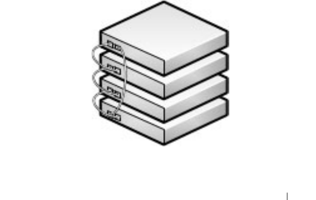
Managing a Switch Stack 195
Stacking and NSF Usage Scenarios
Only a few settings are available to control the stacking configuration, such as
the designation of the standby unit or enabling/disabling NSF. The examples
in this section describe how the stacking and NSF feature act in various
environments.
This section contains the following examples:
• Basic Failover
• Preconfiguring a Stack Member
• NSF in the Data Center
• NSF and VoIP
• NSF and DHCP Snooping
• NSF and the Storage Access Network
• NSF and Routed Access
Basic Failover
In this example, the stack has four members that are connected in a ring
topology, as Figure 9-11 shows.
Figure 9-11. Basic Stack Failover

196 Managing a Switch Stack
When all four units are up and running, the show switch CLI command gives
the following output:
console#show switch
At this point, if Unit 2 is powered off or rebooted due to an unexpected
failure, show switch gives the following output:
console#show switch
When the failed unit resumes normal operation, the previous configuration
that exists for that unit is reapplied by the stack master.
To permanently remove the unit from the stack, enter into Stack Config
Mode and use the member command, as the following example shows.
console#configure
console(config)#stack
console(config-stack)#no member 2
console(config-stack)#exit
console(config)#exit
console#show switch
SW Management
Status
Standby
Status
Preconfig
Model ID
Plugged-
in Model
ID
Switch
Status
Code
Version
--- --------- ------- -------- --------- ------- --------
1 Stack Member N3048 N3048 OK 6.0.0.0
2 Stack Member N3048 N3048 OK 6.0.0.0
3 Mgmt Switch N3048 N3048 OK 6.0.0.0
4 Stack Member N3048 N3048 OK 6.0.0.0
SW Management
Status
Standby
Status
Preconfig
Model ID
Plugged-
in Model
ID
Switch
Status
Code
Version
--- --------- ------- -------- ------------------- --------
1 Stack Member N3048 N3048 OK 6.0.0.0
2 Unassigned N3048 Not Present 0.0.0.0
3 Mgmt Switch N3048 N3048 OK 6.0.0.0
4 Stack Member N3048 N3048 OK 6.0.0.0

Managing a Switch Stack 197
Preconfiguring a Stack Member
To preconfigure a stack member before connecting the physical unit to the
stack, use the show support switchtype command to obtain the SID of the
unit to be added.
The example in this section demonstrates pre-configuring a Dell Networking
switch on a stand-alone Dell Networking switch.
To configure the switch:
1
View the list of SIDs to determine which SID identifies the switch to
preconfigure. The following is the output on N3000 and N2000 series
switches.
console#show supported switchtype
SID Switch Model ID
--- --------------------------------
1 N3024
2 N3024F
3 N3024P
4 N3048
5 N3048P
6 N2024
7 N2024P
8 N2048
9 N2048P
NOTE: N2000 and N3000 switches cannot be stacked together.
SW Management
Status
Standby
Status
Preconfig
Model ID
Plugged-
in Model
ID
Switch
Status
Code
Version
--- --------- ------- -------- ------------------- --------
1 Stack Member N3048 N3048 OK 6.0.0.0
3 Mgmt Switch N3048 N3048 OK 6.0.0.0
4 Stack Member N3048 N3048 OK 6.0.0.0

198 Managing a Switch Stack
2
Preconfigure the switch (SID = 2) as member number 2 in the stack.
console#configure
console(config)#stack
console(config-stack)#member 2 2
console(config-stack)#exit
console(config)#exit
3
Confirm the stack configuration. Some of the fields have been omitted
from the following output due to space limitations.
console#show switch
Management Standby Preconfig Plugged-in Switch Code
SW Status Status Model ID Model ID Status Version
--- ---------- --------- ------------- ------------- ------------- -----------
1 Mgmt Sw N3048 N3048 OK 6.0.0.0
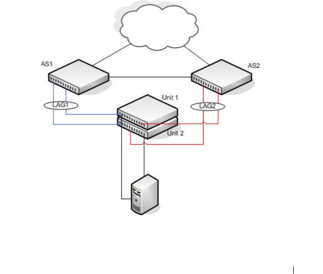
Managing a Switch Stack 199
NSF in the Data Center
Figure 9-12 illustrates a data center scenario, where the stack of two Dell
Networking switches acts as an access switch. The access switch is connected
to two aggregation switches, AS1 and AS2. The stack has a link from two
different units to each aggregation switch, with each pair of links grouped
together in a LAG. The two LAGs and link between AS1 and AS2 are
members of the same VLAN. Spanning tree is enabled on the VLAN. Assume
spanning tree selects AS1 as the root bridge. Assume the LAG to AS1 is the
root port on the stack and the LAG to AS2 is discarding. Unit 1 is the stack
master. If unit 1 fails, the stack removes the Unit 1 link to AS1 from its LAG.
The stack forwards outgoing packets through the Unit 2 link to AS1 during
the failover. During the failover, the stack continues to send BPDUs and LAG
PDUs on its links on Unit 2. The LAGs stay up (with one remaining link in
each), and spanning tree on the aggregation switches does not see a topology
change.
Figure 9-12. Data Center Stack Topology
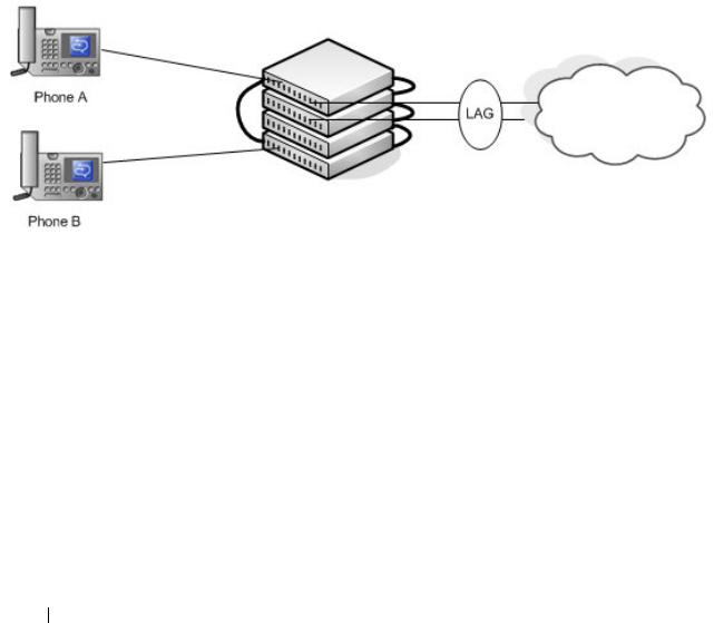
200 Managing a Switch Stack
NSF and VoIP
Figure 9-13 shows how NSF maintains existing voice calls during a stack
master failure. Assume the top unit is the stack master. When the stack
master fails, the call from phone A is immediately disconnected. The call
from phone B continues. On the uplink, the forwarding plane removes the
failed LAG member and continues using the remaining LAG member. If
phone B has learned VLAN or priority parameters through LLDP-MED, it
continues to use those parameters. The stack resumes sending LLDPDUs
with MED TLVs once the control plane restarts. Phone B may miss an
LLDPDU from the stack, but should not miss enough PDUs to revert its
VLAN or priority, assuming the administrator has not reduced the LLDPDU
interval or hold count. If phone B is receiving quality of service from policies
installed in the hardware, those policies are retained across the stack master
restart.
Figure 9-13. NSF and VoIP
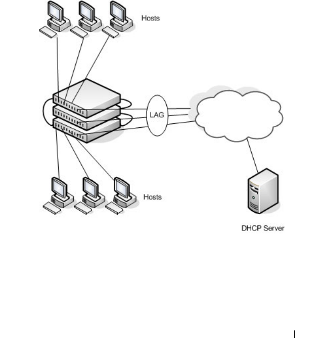
Managing a Switch Stack 201
NSF and DHCP Snooping
Figure 9-14 illustrates an L2 access switch running DHCP snooping. DHCP
snooping only accepts DHCP server messages on ports configured as
trusted
ports. DHCP snooping listens to DHCP messages to build a bindings
database that lists the IP address the DHCP server has assigned to each host.
IP Source Guard (IPSG) uses the bindings database to filter data traffic in
hardware based on source IP address and source MAC address. Dynamic ARP
Inspection (DAI) uses the bindings database to verify that ARP messages
contain a valid sender IP address and sender MAC address. DHCP snooping
checkpoints its bindings database.
Figure 9-14. NSF and DHCP Snooping
If the stack master fails, all hosts connected to that unit lose network access
until that unit reboots. The hardware on surviving units continues to enforce
source filters IPSG installed prior to the failover. Valid hosts continue to
communicate normally. During the failover, the hardware continues to drop
data packets from unauthorized hosts so that security is not compromised.

202 Managing a Switch Stack
If a host is in the middle of an exchange with the DHCP server when the
failover occurs, the exchange is interrupted while the control plane restarts.
When DHCP snooping is enabled, the hardware traps all DHCP packets to
the CPU. The control plane drops these packets during the restart. The
DHCP client and server retransmit their DHCP messages until the control
plane has resumed operation and messages get through. Thus, DHCP
snooping does not miss any new bindings during a failover.
As DHCP snooping applies its checkpointed DHCP bindings, IPSG confirms
the existence of the bindings with the hardware by reinstalling its source IP
address filters.
If Dynamic ARP Inspection is enabled on the access switch, the hardware
traps ARP packets to the CPU on untrusted ports. During a restart, the
control plane drops ARP packets. Thus, new traffic sessions may be briefly
delayed until after the control plane restarts.
If IPSG is enabled and a DHCP binding is not checkpointed to the backup
unit before the failover, that host will not be able to send data packets until it
renews its IP address lease with the DHCP server.
NSF and the Storage Access Network
Figure 9-15 illustrates a stack of three Dell Networking switches connecting
two servers (iSCSI initiators) to a disk array (iSCSI targets). There are two
iSCSI connections as follows:
Session A: 10.1.1.10 to 10.1.1.3
Session B: 10.1.1.11 to 10.1.1.1
An iSCSI application running on the stack master (the top unit in the
diagram) has installed priority filters to ensure that iSCSI traffic that is part
of these two sessions receives priority treatment when forwarded in hardware.
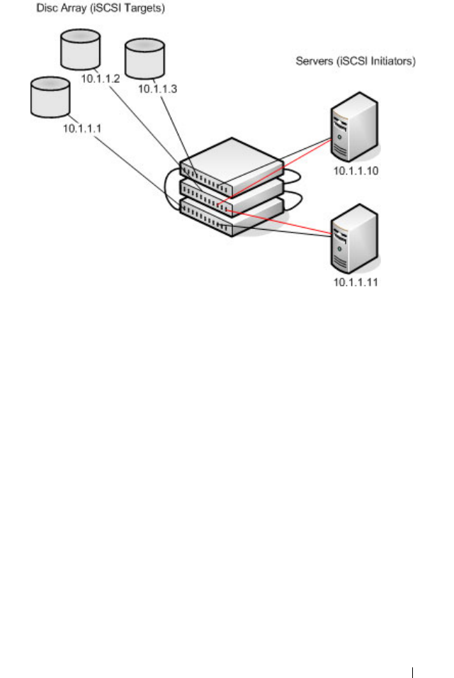
Managing a Switch Stack 203
Figure 9-15. NSF and a Storage Area Network
When the stack master fails, session A drops. The initiator at 10.1.1.10
detects a link down on its primary NIC and attempts to reestablish the
session on its backup NIC to a different IP address on the disk array. The
hardware forwards the packets to establish this new session, but assuming the
session is established before the control plane is restarted on the backup unit,
the new session receives no priority treatment in the hardware.
Session B remains established and fully functional throughout the restart and
continues to receive priority treatment in the hardware.
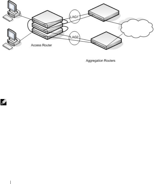
204 Managing a Switch Stack
NSF and Routed Access
Figure 9-16 shows a stack of three units serving as an access router for a set of
hosts. Two LAGs connect the stack to two aggregation routers. Each LAG is a
member of a VLAN routing interface. The stack has OSPF and PIM
adjacencies with each of the aggregation routers. The top unit in the stack is
the stack master.
Figure 9-16. NSF and Routed Access
If the stack master fails, its link to the aggregation router is removed from the
LAG. When the control plane restarts, both routing interfaces come back up
by virtue of the LAGs coming up. OSPF sends grace LSAs to inform its OSPF
neighbors (the aggregation routers) that it is going through a graceful restart.
The grace LSAs reach the neighbors before they drop their adjacencies with
the access router. PIM starts sending hello messages to its neighbors on the
aggregation routers using a new generation ID to prompt the neighbors to
quickly resend multicast routing information. PIM neighbors recognize the
new generation ID and immediately relay the group state back to the
restarting router. IGMP sends queries to relearn the hosts' interest in
multicast groups. IGMP tells PIM the group membership, and PIM sends
NOTE: The graceful restart feature for OSPF is disabled by default. For information
about the web pages and commands to configure NSF for OSPF or OSPFv3, see
"Configuring OSPF and OSPFv3" on page 1111.

Managing a Switch Stack 205
JOIN messages upstream. The control plane updates the driver with
checkpointed unicast routes. The forwarding plane reconciles L3 hardware
tables.
The OSPF graceful restart finishes, and the control plane deletes any stale
unicast routes not relearned at this point. The forwarding plane reconciles L3
multicast hardware tables. Throughout the process, the hosts continue to
receive their multicast streams, possibly with a short interruption as the top
aggregation router learns that one of its LAG members is down. The hosts see
no more than a 50 ms interruption in unicast connectivity.

206 Managing a Switch Stack

Configuring Authentication, Authorization, and Accounting
10
Configuring Authentication,
Authorization, and Accounting
This chapter describes how to control access to the switch management
interface using authentication and authorization. It also describes how to
record this access using accounting. Together the three services are referred to
by the acronym AAA.
The topics covered in this chapter include:
• AAA Overview
• Authentication
• Authorization
• Accounting
• Authentication Examples
• Authorization Examples
• Using RADIUS Servers to Control Management Access
• Using TACACS+ Servers to Control Management Access
• Default Configurations
AAA Overview
AAA is a framework for configuring management security in a consistent way.
Three services make up AAA:
• Authentication—Validates the user identity. Authentication takes place
before the user is allowed access to switch services.
• Authorization—Determines which services the user is allowed to access.
• Accounting—Collects and sends security information about users and
commands.

208 Configuring Authentication, Authorization, and Accounting
Each service is configured using method lists. The method lists define how
each service is to be performed by specifying the methods available to
perform a service. The first method in a list is tried first. If the first method
returns an error, the next method in the list is tried. This continues until all
methods in the list have been attempted. If no method can perform the
service, then the service fails. A method may return an error due to lack of
network access, misconfiguration of a server, and other reasons. If there is no
error, the method returns success if the user is allowed access to the service
and failure if the user is not.
AAA gives the user flexibility in configuration by allowing different method
lists to be assigned to different access lines. In this way, it is possible to
configure different security requirements for the serial console than for
Telnet, for example.
Methods
A method performs the configured service. Not every method is available for
every service. Some methods require a username and password and other
methods only require a password. Table 10-1 summarizes the various
methods:
Table 10-1. AAA Methods
Method Username? Password? Can Return an Error?
enable no yes yes
ias yes yes no
line no yes yes
local yes yes yes
none no no no
radius yes yes yes
tacacs yes yes yes

Configuring Authentication, Authorization, and Accounting 209
Methods that never return an error cannot be followed by any other methods
in a method list.
•The
enable
method uses the enable password. If there is no enable
password defined, then the enable method will return an error.
•The
ias
method is a special method that is only used for 802.1X. It uses an
internal database (separate from the local user database) that acts like an
802.1X authentication server. This method never returns an error. It will
always pass or deny a user.
•The
line
method uses the password for the access line on which the user is
accessing the switch. If there is no line password defined for the access
line, then the line method will return an error.
•The
local
method uses the local user database. If the user password does
not match, then access is denied. This method returns an error if the user
name is not present in the local user database.
•The
none
method does not perform any service, but instead always returns
a result as if the service had succeeded. This method never returns an error.
If none is configured as a method, the user will always be authenticated
and allowed to access the switch.
•The
radius
and
tacacs
methods communicate with servers running the
RADIUS and TACACS+ protocols, respectively. These methods can
return an error if the switch is unable to contact the server.
Access Lines
There are five access lines: console, Telnet, SSH, HTTP, and HTTPS. HTTP
and HTTPS are not configured using AAA method lists. Instead, the
authentication list for HTTP and HTTPS is configured directly
(authorization and accounting are not supported). The default method lists
for both the HTTP and HTTPS access lines consist of only the local method.
Each of the other access lines may be assigned method lists independently for
the AAA services.
The SSH line has built-in authentication beyond that configured by the
administrator.
In the SSH protocol itself, there are multiple methods for authentication.
These are not the authentication methods configured in AAA, but are
internal to SSH itself. When an SSH connection is attempted, the challenge-
response method is specified in the connection request.

210 Configuring Authentication, Authorization, and Accounting
The methods available for authentication are: host-based authentication,
public key authentication, challenge-response authentication, and password
authentication. Authentication methods are tried in the order specified
above, although SSH-2 has a configuration option to change the default
order.
Host-based authentication operates as follows:
If the host from which the user logs in is listed in a specific file
(/etc/hosts.equiv or /etc/ssh/shosts.equiv) on the remote host, and the user
names are the same on both hosts, or if the files ~/.rhosts or ~/.shosts exist in
the user's home directory on the remote host and contain a line containing
the name of the client machine and the name of the user on that machine,
the user is considered for login. Additionally, the server must be able to verify
the client's host key for login to be permitted. This authentication method
closes security holes due to IP spoofing, DNS spoofing, and routing spoofing.
This authentication method is not implemented by DNOS.
Public key authentication operates as follows:
The administrator first generates a pair of encryption keys, the "public" key
and the "private" key. Messages encrypted with the private key can only be
decrypted by the public key, and vice-versa. The administrator keeps the
private key on his/her local machine, and loads the public key on to the
switch. When the administrator attempts to log into the switch, the protocol
sends a brief message, encrypted with the public key. If the switch can decrypt
the message (and can send back some proof that it has done so) then the
response proves that switch must possess the private key, and user is
authenticated without giving a username/password.
This method is implemented in DNOS. If the user does not present a
certificate, it is not considered an error, and authentication will continue with
challenge-response authentication.
Challenge-response authentication works as follows:
The switch sends an arbitrary "challenge" text and prompts for a response.
SSH-2 allows multiple challenges and responses; SSH-1 is restricted to one
challenge/response only. Examples of challenge-response authentication
include BSD Authentication.
Finally, if all other authentication methods fail, SSH prompts the user for a
password.

Configuring Authentication, Authorization, and Accounting 211
Authentication
Authentication is the process of validating a user's identity. During the
authentication process, only identity validation is done. There is no
determination made of which switch services the user is allowed to access.
This is true even when RADIUS is used for authentication; RADIUS cannot
perform separate transactions for authentication and authorization. However,
the RADIUS server can provide attributes during the authentication process
that are used in the authorization process.
Authentication Types
There are three types of authentication:
•
Login
— Login authentication grants access to the switch if the user
credentials are validated. Access is granted only at privilege level one.
•
Enable
—Enable authentication grants access to a higher privilege level if
the user credentials are validated for the higher privilege level. When
RADIUS is used for enable authentication, the username for this request is
always $enab15$. The username used to log into the switch is not used for
RADIUS enable authentication.
•
Dot1x
—Dot1x authentication is used to grant an 802.1X supplicant access
to the network. For more information about 802.1X, see
"Configuring Port
and System Security
" on page 503
.
Table 10-2 shows the valid methods for each type of authentication:
Table 10-2. Valid Methods for Authentication Types
Method Login Enable Dot1x
enable yes yes no
iasnonoyes
line yes yes no
local yes no no
none yes yes yes
radius yes yes yes
tacacs yes yes no

212 Configuring Authentication, Authorization, and Accounting
Authorization
Authorization is used to determine which services the user is allowed to
access. For example, the authorization process may assign a user’s privilege
level, which determines the set of commands the user can execute. There are
three kinds of authorization: commands, exec, and network.
•
Commands
: Command authorization determines which CLI commands
the user is authorized to execute.
•
Exec
: Exec authorization determines what the user is authorized to do on
the switch; that is, the user’s privilege level and an administrative profile.
•
Network
: Network authorization enables a RADIUS server to assign a
particular 802.1X supplicant to a VLAN. For more information about
802.1X, see
"Configuring Port and System Security
" on page 503
.
Table 10-3 shows the valid methods for each type of authorization:
Exec Authorization Capabilities
Dell Networking switches support two types of service configuration with
exec authorization: privilege level and administrative profiles.
Privilege Level
By setting the privilege level during exec authorization, a user can be placed
directly into Privileged EXEC mode when they log into the command line
interface.
Table 10-3. Authorization Methods
Method Commands Exec Network
local no yes no
none yes yes no
radius no yes yes
tacacs yes yes no

Configuring Authentication, Authorization, and Accounting 213
Administrative Profiles
The Administrative Profiles feature allows the network administrator to
define a list of rules that control the CLI commands available to a user. These
rules are collected in a “profile.” The rules in a profile can define the set of
commands, or a command mode, to which a user is permitted or denied
access.
Within a profile, rule numbers determine the order in which the rules are
applied. When a user enters a CLI command, rules within the first profile
assigned to the user are applied in descending order until there is a rule that
matches the input. If no rule permitting the command is found, then the
other profiles assigned to the user (if any) are searched for rules permitting
the command. Rules may use regular expressions for command matching. All
profiles have an implicit “deny all” rule, such that any command that does
not match any rule in the profile is considered to have been denied by that
profile.
A user can be assigned to more than one profile. If there are conflicting rules
in profiles, the “permit” rule always takes precedence over the “deny” rule.
That is, if any profile assigned to a user permits a command, then the user is
permitted access to that command. A user may be assigned up to 16 profiles.
A number of profiles are provided by default. These profiles cannot be altered
by the switch administrator. See "Administrative Profiles" on page 240 for the
list of default profiles.
If the successful authorization method does not provide an administrative
profile for a user, then the user is permitted access based upon the user's
privilege level. This means that, if a user successfully passes enable
authentication or if exec authorization assigns a privilege level, the user is
permitted access to all commands. This is also true if none of the
administrative profiles provided are configured on the switch. If some, but
not all, of the profiles provided in the authentication are configured on the
switch, then the user is assigned the profiles that exist, and a message is
logged that indicates which profiles could not be assigned.

214 Configuring Authentication, Authorization, and Accounting
Accounting
Accounting is used to record security events, such as a user logging in or
executing a command. Accounting records may be sent upon completion of
an event (stop-only) or at both the beginning and end of an event (start-
stop). There are three types of accounting: commands, Dot1x, and exec.
•
Commands
—Sends accounting records for command execution.
•
Dot1x
—Sends accounting records for network access.
•
Exec
—Sends accounting records for management access (logins).
For more information about the data sent in accounting records, see "Which
RADIUS Attributes Does the Switch Support?" on page 234 and "Using
TACACS+ Servers to Control Management Access" on page 237.
Table 10-4 shows the valid methods for each type of accounting:
Table 10-4. Accounting Methods
Method Commands Dot1x Exec
radius no yes yes
tacacs yes no yes

Configuring Authentication, Authorization, and Accounting 215
Authentication Examples
It is important to understand that during authentication, all that happens is
that the user is validated. If any attributes are returned from the server, they
are not processed during authentication. In the examples below, it is assumed
that the default configuration of authorization—that is, no authorization—is
used.
Local Authentication Example
Use the following configuration to require local authentication when logging
in over a Telnet connection:
aaa authentication login “loc” local
line telnet
login authentication loc
exit
enable password PaSSW0rd
username guest password password
passwords strength minimum numeric-characters 2
passwords strength minimum character-classes 4
passwords strength-check
username admin password paSS1&word2 privilege 15
passwords lock-out 3
The following describes each line of this code:
•The
aaa authentication login “loc” local
command creates a login
authentication list called “loc” that contains the method local.
•The
line telnet
command enters the configuration mode for the Telnet
line.
•The
login authentication loc
command assigns the loc login
authentication list to be used for users accessing the switch via Telnet.
• The enable password allows Telnet and SSH users access to privileged exec
mode. It is required that an enable password be configured to allow local
access users to elevate to privileged exec level.
•The
username guest password password
command creates a user with the
name “guest” and password “password”. A simple password can be
configured here, since strength-checking has not yet been enabled.

216 Configuring Authentication, Authorization, and Accounting
•The
passwords strength minimum numeric-characters 2
command sets
the minimum number of numeric characters required when password
strength checking is enabled. This parameter is enabled only if the
passwords strength minimum character-classes
parameter is set to
something greater than its default value of 0.
•The
passwords strength minimum character-classes 4
command sets the
minimum number of character classes that must be present in the
password. The possible character classes are: upper-case, lower-case,
numeric and special.
•The
passwords strength-check
command enables password strength
checking.
•The
username admin password paSS1&word2 privilege 15
command
creates a user with the name “admin” and password “paSS1&word2”. This
user is enabled for privilege level 15. Note that, because password strength
checking was enabled, the password was required to have at least two
numeric characters, one uppercase character, one lowercase character, and
one special character.
•The
passwords lock-out 3
command locks out a local user after three
failed login attempts.
This configuration allows either user to log into the switch. Both users will
have privilege level 1. If no enable password was configured, neither user
would be able to successfully execute the enable command, which grants
access to Privileged EXEC mode, because there is no enable password set by
default (the default method list for Telnet enable authentication is only the
“enable” method).
NOTE: It is recommend that the password strength checking and password
lockout features be enabled when configuring local users.

Configuring Authentication, Authorization, and Accounting 217
TACACS+ Authentication Example
Use the following configuration to require TACACS+ authentication when
logging in over a Telnet connection:
aaa authentication login “tacplus” tacacs
aaa authentication enable “tacp” tacacs
tacacs-server host 1.2.3.4
key “secret”
exit
line telnet
login authentication tacplus
enable authentication tacp
exit
The following describes each line in the above configuration:
•The
aaa authentication login “tacplus” tacacs
command creates a login
authentication list called “tacplus” that contains the method tacacs. If this
method returns an error, the user will fail to login.
•The
aaa authentication enable “tacp” tacacs
command creates an enable
authentication list called “tacp” that contains the method tacacs. If this
method fails, then the user will fail to execute the enable command.
•The
tacacs-server host 1.2.3.4
command is the first step in defining a
TACACS+ server at IP address 1.2.3.4. The result of this command is to
place the user in tacacs-server mode to allow further configuration of the
server.
•The
key “secret”
command defines the shared secret. This must be the
same as the shared secret defined on the TACACS+ server.
•The
line telnet
command enters the configuration mode for the Telnet
line.
•The
login authentication tacplus
command assigns the tacplus login
authentication method list to be used for users accessing the switch via
Telnet.
•The
enable authentication tacp
command assigns the tacp enable
authentication method list to be used for users executing the enable
command when accessing the switch via Telnet.

218 Configuring Authentication, Authorization, and Accounting
Public Key SSH Authentication Example
The following is an example of a public key configuration for SSH login.
Using a tool such as putty and a private/public key infrastructure, one can
enable secure login to the Dell Networking switch without a password.
Instead, a public key is used with a private key kept locally on the
administrator's computer. The public key can be placed on multiple devices,
allowing the administrator secure access without needing to remember
multiple passwords. It is strongly recommended that the private key be
protected with a password.
This configuration requires entering a public key, which can be generated by a
tool such as PuTTYgen. Be sure to generate the correct type of key. In this
case, we use an RSA key with the SSH-2 version of the protocol.
Switch Configuration
username "admin" password f4d77eb781360c5711ecf3700a7af623 privilege 15 encrypted
aaa authentication login "NOAUTH" line
aaa authentication enable "NOAUTH" line
crypto key generate rsa
crypto key pubkey-chain ssh user-key "admin" rsa
key-string row AAAAB3NzaC1yc2EAAAABJQAAAIBor6DPjYDpSy8Qcji68xrS/4Lf8c9Jq4xXKIZ5
Pvv20AkRFE0ifVI9EH4jyZagR3wzH5Xl9dyjA6bTuqMgN15C1xJC1l59FU88JaY7
ywGdRppmoaJrNRPM7RZtQPaDVIunzm3eMr9PywwQ0umsHWGNexUrDYHFWRIAmJp6
89AAxw==
exit
line ssh
login authentication defaultList
exit
ip ssh server
ip ssh pubkey-auth
ip ssh protocol 2
The following describes each line of the above configuration:
The username command creates a switch administrator.
The aaa authentication lines set the login and enable methods for line to
NOAUTH.
The crypto key generate command generates an internal RSA key. This step is
not required if an internal RSA key has been generated before on this switch.
NOTE: A user logging in with this configuration would be placed in User EXEC
mode with privilege level 1. To access Privileged EXEC mode with privilege level 15,
use the enable command.

Configuring Authentication, Authorization, and Accounting 219
The crypto key pubkey-chain ssh command sets SSH to use a public key for
the specified administrator login. The user login is specified by the username
command, not the ias-user command.
The key-string command enters the public key obtained from a key authority
or from a tool such as PuTTyGen. This command is entered as a single line,
not as four lines as it appears in the text above.
The line ssh command sets the line method to SSH.
The login authentication command configures the authentication method to
the defaultList. The defaultList contains a single method — none — which is
equivalent to no authentication. Since the authentication is provided by the
public key, a second layer of authentication is not required.
The last three lines enable the SSH server, configure it to use public key
authentication, and specify use of the SSH-2 protocol.
The following shows the configured authentication methods:
console(config)#show authentication methods
Login Authentication Method Lists
---------------------------------
defaultList : none
networkList : local
NOAUTH : line
Enable Authentication Method Lists
----------------------------------
enableList : enable none
enableNetList : enable
NOAUTH : line
Line Login Method List Enable Method List
------- ----------------- ------------------
Console defaultList enableList
Telnet networkList enableList
SSH defaultList enableList
HTTPS :local
HTTP :local
DOT1X :
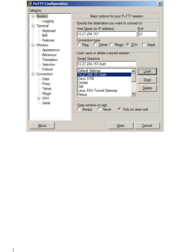
220 Configuring Authentication, Authorization, and Accounting
PUTTY Configuration
Main Screen
On the following screen, the IP address of the switch is configured and SSH is
selected as the secure login protocol.
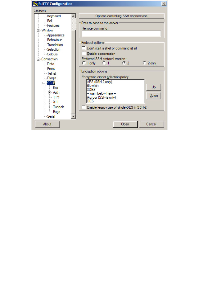
Configuring Authentication, Authorization, and Accounting 221
On the next screen, PUTTY is configured to use SSH-2 only. This is an
optional step that accelerates the login process.
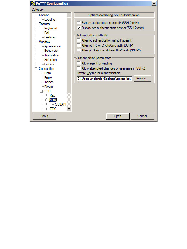
222 Configuring Authentication, Authorization, and Accounting
The following screen is the key to the configuration. It is set to display the
authentication banner, disable authentication with Pageant, disable keyboard-
interactive authentication (unless desired), disable attempted changes of user
name, and select the private key file used to authenticate with the switch.
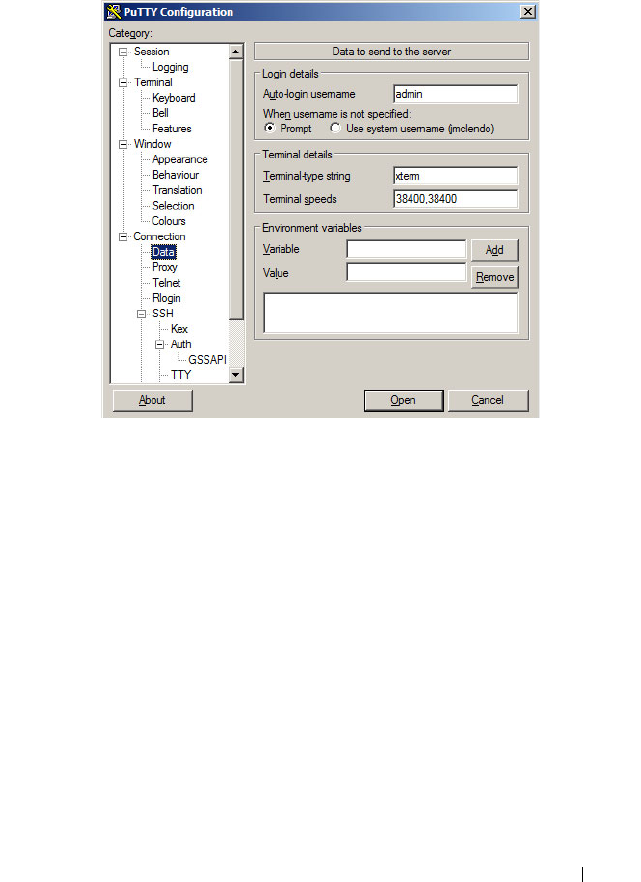
Configuring Authentication, Authorization, and Accounting 223
The following screen configures the user name to be sent to the switch. A user
name is always required. Alternatively, leave Auto-login name blank and the
system will prompt for a user name.
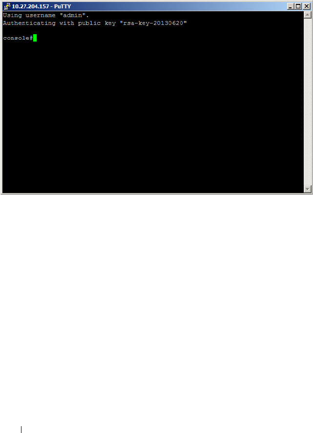
224 Configuring Authentication, Authorization, and Accounting
After configuring Putty, be sure to save the configuration. The following
screen shows the result of the login process. The user name is entered
automatically and the switch confirms that public key authentication occurs.
Configuring Authentication, Authorization, and Accounting 225
Authenticating Without a Public Key
When authenticating without the public key, the switch prompts for the user
name and password. This is a SSH function, not a switch function. If the user
knows the administrator login and password, then they are able to
authenticate in this manner.
RADIUS Authentication Example
Use the following configuration to require RADIUS authentication to login
over a Telnet connection:
aaa authentication login “rad” radius
aaa authentication enable “raden” radius
radius-server host 1.2.3.4
key “secret”
exit
line telnet
login authentication rad
enable authentication raden
exit
The following describes each line in the above configuration:

226 Configuring Authentication, Authorization, and Accounting
•The
aaa authentication login “rad” radius
command creates a login
authentication list called “rad” that contains the method radius. If this
method returns an error, the user will fail to login.
•The
aaa authentication enable “raden” radius
command creates an
enable authentication list called “raden” that contains the method radius.
If this method fails, then the user will fail to execute the enable command.
•The
radius-server host 1.2.3.4
command is the first step in defining a
RADIUS server at IP address 1.2.3.4. The result of this command is to
place the user in radius-server mode to allow further configuration of the
server.
•The
key “secret”
command defines the shared secret. This must be the
same as the shared secret defined on the RADIUS server.
•The
line telnet
command enters the configuration mode for the Telnet
line.
•The
login authentication rad
command assigns the rad login
authentication method list to be used for users accessing the switch via
Telnet.
•The
enable authentication raden
command assigns the raden enable
authentication method list to be used for users executing the enable
command when accessing the switch via Telnet.

Configuring Authentication, Authorization, and Accounting 227
Authorization Examples
Authorization allows the administrator to control which services a user is
allowed to access. Some of the things that can be controlled with
authorization include the user's initial privilege level and which commands
the user is allowed to execute. When authorization fails, the user is denied
access to the switch, even though the user has passed authentication.
The following examples assume that the configuration used in the previous
examples has already been applied.
Local Authorization Example—Direct Login to Privileged EXEC Mode
Apply the following configuration to use the local user database for
authorization, such that a user can enter privileged EXEC mode directly:
aaa authorization exec “locex” local
line telnet
authorization exec locex
exit
With the users that were previously configured, the guest user will still log
into user EXEC mode, since the guest user only has privilege level 1 (the
default). The admin user will be able to login directly to privileged EXEC
mode since his privilege level was configured as 15.
TACACS+ Authorization Example—Direct Login to Privileged EXEC
Mode
Apply the following configuration to use TACACS+ for authorization, such
that a user can enter privileged EXEC mode directly:
aaa authorization exec “tacex” tacacs
line telnet
authorization exec tacex
exit
Configure the TACACS+ server so that the shell service is enabled and the
priv-lvl attribute is sent when user authorization is performed. For example:
shell:priv-lvl=15
The following describes each line in the above configuration:

228 Configuring Authentication, Authorization, and Accounting
•The
aaa authorization exec “tacex” tacacs
command creates an exec
authorization method list called tacex which contains the method tacacs.
•The
authorization exec tacex
command assigns the tacex exec
authorization method list to be used for users accessing the switch via
Telnet.
Notes:
• If the privilege level is zero (that is, blocked), then authorization will fail
and the user will be denied access to the switch.
• If the privilege level is higher than one, the user will be placed directly in
Privileged EXEC mode. Note that all commands in Privileged EXEC mode
require privilege level 15, so assigning a user a lower privilege level will be
of no value.
• A privilege level greater than 15 is invalid and treated as if privilege level
zero had been supplied.
• The shell service must be enabled on the TACACS+ server. If this service
is not enabled, authorization will fail and the user will be denied access to
the switch.
TACACS+ Authorization Example—Administrative Profiles
The switch should use the same configuration as for the previous
authorization example.
The TACACS+ server should be configured such that it will send the “roles”
attribute. For example:
shell:roles=router-admin
The above example attribute will give the user access to the commands
permitted by the router-admin profile.
NOTE: If the priv-lvl attribute is also supplied, the user can also be placed directly
into privileged EXEC mode.

Configuring Authentication, Authorization, and Accounting 229
TACACS+ Authorization Example—Custom Administrative Profile
This example creates a custom profile that allows the user to control user
access to the switch by configuring a administrative profile that only allows
access to AAA related commands. Use the following commands to create the
administrative profile:
admin-profile aaa
rule 99 permit command “^show aaa .*”
rule 98 permit command “^show authentication .*”
rule 97 permit command "^show authorization .*”
rule 96 permit command “^show accounting .*”
rule 95 permit command “^show tacacs .*”
rule 94 permit command “^aaa .*”
rule 93 permit command “^line .*”
rule 92 permit command “^login .*”
rule 91 permit command “^authorization .*”
rule 90 permit command “^accounting .*”
rule 89 permit command “^configure .*”
rule 88 permit command “^password .*”
rule 87 permit command “^username .*”
rule 86 permit command “^show user.*"
rule 85 permit command “^radius-server .*”
rule 84 permit command “^tacacs-server .*”
rule 83 permit mode radius-auth-config
rule 82 permit mode radius-acct-config
rule 81 permit mode tacacs-config
exit
The following describes each line in the above configuration:
•The
admin-profile aaa
command will create an administrative profile call
aaa and place the user in admin-profile-config mode.
•Each
rule
number
permit command
regex
command allows any
command that matches the regular expression.
•Each
rule
number
permit mode
mode-name
command allows all
commands in the named mode.
• The command rules use regular expressions as implemented by Henry
Spencer's regex library (the POSIX 1003.2 compliant version). In the
regular expressions used in this example, the caret (^) matches the null

230 Configuring Authentication, Authorization, and Accounting
string at the beginning of a line, the period (.) matches any single
character, and the asterisk (*) repeats the previous match zero or more
times.
• To assign this profile to a user, configure the TACACS+ server so that it
sends the following “roles” attribute for the user:
shell:roles=aaa
If it is desired to also permit the user access to network-operator
commands (basically, all the command in User EXEC mode), then the
“roles” attribute would be configured as follows:
shell:roles=aaa,network-operator
TACACS+ Authorization Example—Per-command Authorization
An alternative method for command authorization is to use the TACACS+
feature of per-command authorization. With this feature, every time the user
enters a command, a request is sent to the TACACS+ server to ask if the user
is permitted to execute that command. Exec authorization does not need to
be configured to use per-command authorization.
Apply the following configuration to use TACACS+ to authorize commands:
aaa authorization commands “taccmd” tacacs
line telnet
authorization commands taccmd
exit
The following describes each line in the above configuration:
•The
aaa authorization commands “taccmd” tacacs
command creates a
command authorization method list called taccmd that includes the
method tacacs.
•The
authorization commands taccmd
command assigns the taccmd
command authorization method list to be used for users accessing the
switch via Telnet.
The TACACS+ server must be configured with the commands that the user
is allowed to execute. If the server is configured for command authorization
as “None”, then no commands will be authorized. If both administrative

Configuring Authentication, Authorization, and Accounting 231
profiles and per-command authorization are configured for a user, any
command must be permitted by both the administrative profiles and by per-
command authorization.
RADIUS Authorization Example—Direct Login to Privileged EXEC Mode
Apply the following configuration to use RADIUS for authorization, such that
a user can enter privileged exec mode directly:
aaa authorization exec “rad” radius
line telnet
authorization exec rad
exit
Configure the RADIUS server so that the RADIUS attribute Service Type (6)
is sent with value Administrative. Any value other than Administrative is
interpreted as privilege level 1.
The following describes each line in the above configuration:
•The
aaa authorization exec “rad” radius
command creates an exec
authorization method list called “rad” that contains the method radius.
•The
authorization exec rad
command assigns the rad exec authorization
method list to be used for users accessing the switch via Telnet.
Notes:
• If the privilege level is zero (that is, blocked), then authorization will fail
and the user will be denied access to the switch.
• If the privilege level is higher than one, the user will be placed directly in
Privileged EXEC mode. Note that all commands in Privileged EXEC mode
require privilege level 15, so assigning a user a lower privilege level will be
of no value.
• A privilege level greater than 15 is invalid and treated as if privilege level
zero had been supplied.

232 Configuring Authentication, Authorization, and Accounting
RADIUS Authorization Example—Administrative Profiles
The switch should use the same configuration as in the previous
authorization example.
The RADIUS server should be configured such that it will send the Cisco AV
Pair attribute with the “roles” value. For example:
shell:roles=router-admin
The above example attribute gives the user access to the commands
permitted by the router-admin profile.
Using RADIUS Servers to Control Management
Access
The RADIUS client on the switch supports multiple RADIUS servers. When
multiple authentication servers are configured, they can help provide
redundancy. One server can be designated as the primary and the other(s) will
function as backup server(s). The switch attempts to use the primary server
first. if the primary server does not respond, the switch attempts to use the
backup servers. A priority value can be configured to determine the order in
which the backup servers are contacted.
How Does RADIUS Control Management Access?
Many networks use a RADIUS server to maintain a centralized user database
that contains per-user authentication information. RADIUS servers provide a
centralized authentication method for:
• Telnet Access
•Web Access
• Console to Switch Access
• Access Control Port (802.1X)
Like TACACS+, RADIUS access control utilizes a database of user
information on a remote server. Making use of a single database of accessible
information—as in an Authentication Server—can greatly simplify the
authentication and management of users in a large network. One such type of
Authentication Server supports the Remote Authentication Dial In User
Service (RADIUS) protocol as defined by RFC 2865.
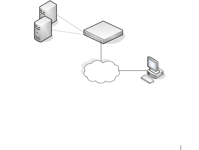
Configuring Authentication, Authorization, and Accounting 233
For authenticating users prior to access, the RADIUS standard has become
the protocol of choice by administrators of large accessible networks. To
accomplish the authentication in a secure manner, the RADIUS client and
RADIUS server must both be configured with the same shared password or
“secret”. This “secret” is used to generate one-way encrypted authenticators
that are present in all RADIUS packets. The “secret” is never transmitted over
the network.
RADIUS conforms to a secure communications client/server model using
UDP as a transport protocol. It is extremely flexible, supporting a variety of
methods to authenticate and statistically track users. RADIUS is also
extensible, allowing for new methods of authentication to be added without
disrupting existing functionality.
As a user attempts to connect to the switch management interface, the switch
first detects the contact and prompts the user for a name and password. The
switch encrypts the supplied information, and a RADIUS client transports
the request to a pre-configured RADIUS server.
Figure 10-1. RADIUS Topology
The server can authenticate the user itself or make use of a back-end device to
ascertain authenticity. In either case a response may or may not be
forthcoming to the client. If the server accepts the user, it returns a positive
result with attributes containing configuration information. If the server
`
Management Host
Primary RADIUS Server
Backup RADIUS Server
Management
Network
Dell Networking Switch

234 Configuring Authentication, Authorization, and Accounting
rejects the user, it returns a negative result. If the server rejects the client or
the shared
secrets
differ, the server returns no result. If the server requires
additional verification from the user, it returns a challenge, and the request
process begins again.
If you use a RADIUS server to authenticate users, you must configure user
attributes in the user database on the RADIUS server. The user attributes
include the user name, password, and privilege level.
Which RADIUS Attributes Does the Switch Support?
Table 10-5 lists the RADIUS attributes that the switch supports and indicates
whether the 802.1X feature, user management feature, or Captive Portal
feature supports the attribute. You can configure these attributes on the
RADIUS server(s) when utilizing the switch RADIUS service.
NOTE: To set the privilege level, it is recommended to use the Service-Type
attribute instead of the Cisco AV pair priv-lvl attribute.
Table 10-5. Supported RADIUS Attributes
Type RADIUS Attribute Name 802.1X User Manager Captive Portal
1 USER-NAME Yes Yes No
2 USER-PASSWORD Yes Yes No
4 NAS-IP-ADDRESS Yes No No
5NAS-PORT Yes Yes No
6SERVICE-TYPE No Yes No
11 FILTER-ID Yes No No
12 FRAMED-MTU Yes No No
15 LOGIN-SERVICE No Yes
18 REPLY-MESSAGE Yes Yes No
24 STATE Yes Yes No
25 CLASS Yes No No
26 VENDOR-SPECIFIC No Yes Yes
27 SESSION-TIMEOUT Yes No Yes

Configuring Authentication, Authorization, and Accounting 235
28 IDLE-TIMEOUT No No Yes
29 TERMINATION-ACTION Yes No No
30 CALLED-STATION-ID Yes No No
31 CALLING-STATION-ID Yes No No
32 NAS-IDENTIFIER Yes Yes No
40 ACCT-STATUS-TYPE Set by
RADIUS
client for
Accounting
Yes No
42 ACCT-INPUT-OCTETS Yes No No
43 ACCT-OUTPUT-OCTETS Yes No No
44 ACCT-SESSION-ID Set by
RADIUS
client for
Accounting
Yes No
46 ACCT-SESSION-TIME Yes Yes No
49 ACCT-TERMINATECAUSE Yes No No
52 ACCT-
INPUTGIGAWORDS
Yes No No
53 ACCT-
OUTPUTGIGAWORDS
Yes No No
61 NAS-PORT-TYPE Yes No No
64 TUNNEL-TYPE Yes No No
65 TUNNEL-MEDIUM-TYPE Yes No No
79 EAP-MESSAGE Yes No No
80 MESSAGEAUTHENTICAT
OR
Set by
RADIUS
client for
Accounting
Yes No
81 TUNNEL-
PRIVATEGROUP-ID
Yes No No
Table 10-5. Supported RADIUS Attributes (Continued)
Type RADIUS Attribute Name 802.1X User Manager Captive Portal

236 Configuring Authentication, Authorization, and Accounting
How Are RADIUS Attributes Processed on the Switch?
The following attributes are processed in the RADIUS Access-Accept
message received from a RADIUS server:
• NAS-PORT—ifIndex of the port to be authenticated.
• REPLY-MESSAGE—Trigger to respond to the Access-Accept message
with an EAP notification.
• STATE-RADIUS—Server state. Transmitted in Access-Request and
Accounting-Request messages.
• SESSION-TIMEOUT—Session timeout value for the session (in seconds).
Used by both 802.1X and Captive Portal.
• TERMINATION-ACTION—Indication as to the action taken when the
service is completed.
• EAP-MESSAGE—Contains an EAP message to be sent to the user. This is
typically used for MAB clients.
• VENDOR-SPECIFIC—The following Cisco AV Pairs are supported:
– shell:priv-lvl
– shell:roles
• FILTER-ID—Name of the filter list for this user.
• TUNNEL-TYPE—Used to indicate that a VLAN is to be assigned to the
user when set to tunnel type VLAN (13).
• TUNNEL-MEDIUM-TYPE—Used to indicate the tunnel medium type.
Must be set to medium type 802 (6) to enable VLAN assignment.
• TUNNEL-PRIVATE-GROUP-ID—Used to indicate the VLAN to be
assigned to the user. May be a string which matches a preconfigured VLAN
name or a VLAN id. If a VLAN id is given, the string must only contain
decimal digits.
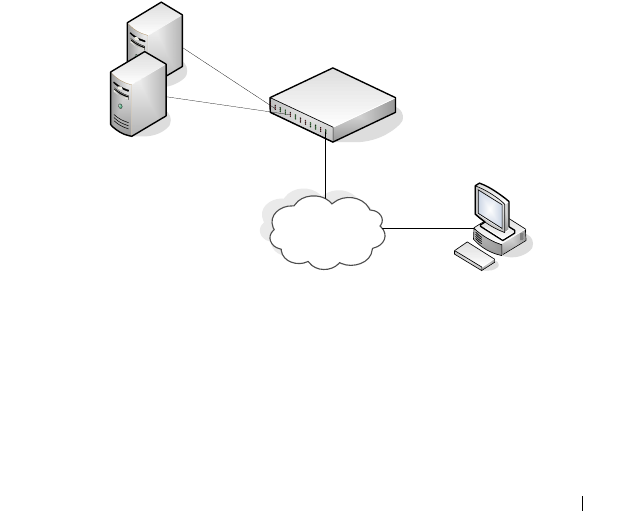
Configuring Authentication, Authorization, and Accounting 237
Using TACACS+ Servers to Control Management
Access
TACACS+ (Terminal Access Controller Access Control System) provides
access control for networked devices via one or more centralized servers.
TACACS+ simplifies authentication by making use of a single database that
can be shared by many clients on a large network. TACACS+ uses TCP to
ensure reliable delivery and a shared key configured on the client and daemon
server to encrypt all messages.
If you configure TACACS+ as the authentication method for user login and a
user attempts to access the user interface on the switch, the switch prompts
for the user login credentials and requests services from the TACACS+
client. The client then uses the configured list of servers for authentication,
and provides results back to the switch.
Figure 10-2 shows an example of access management using TACACS+.
Figure 10-2. Basic TACACS+ Topology
You can configure the TACACS+ server list with one or more hosts defined
via their network IP address. You can also assign each a priority to determine
the order in which the TACACS+ client will contact them. TACACS+
contacts the server when a connection attempt fails or times out for a higher
priority server.
`
Management Host
Primary TACACS+ Server
Backup TACACS+ Server
Management
Network
Dell Networking Switch

238 Configuring Authentication, Authorization, and Accounting
You can configure each server host with a specific connection type, port,
timeout, and shared key, or you can use global configuration for the key and
timeout.
The TACACS+ server can do the authentication itself, or redirect the request
to another back-end device. All sensitive information is encrypted and the
shared secret is never passed over the network; it is used only to encrypt the
data.
Which TACACS+ Attributes Does the Switch Support?
Table 10-6 lists the TACACS+ attributes that the switch supports and
indicates whether the authorization or accounting service supports sending or
receiving the attribute. The authentication service does not use attributes.
You can configure these attributes on the TACACS+ server(s) when utilizing
the switch TACACS+ service.
Table 10-6. Supported TACACS+ Attributes
Attribute Name Exec Authorization Command
Authorization
Accounting
cmd both (optional) sent sent
cmd-arg sent
elapsed-time sent
priv-lvl received
protocol sent
roles both (optional)
service=shell both sent sent
start-time sent
stop-time sent

Configuring Authentication, Authorization, and Accounting 239
Default Configurations
Method Lists
The method lists shown in Table 10-7 are defined by default. They cannot be
deleted, but they can be modified. Using the “no” command on these lists
will return them to their default configuration.
Access Lines (AAA)
Table 10-8 shows the method lists assigned to the various access lines by
default.
Table 10-7. Default Method Lists
AAA Service (type) List Name List Methods
Authentication (login) defaultList none
Authentication (login) networkList local
Authentication (enable) enableList enable none
Authentication (enable) enableNetList enable
Authorization (exec) dfltExecAuthList none
Authorization (commands) dfltCmdAuthList none
Accounting (exec) dfltExecList tacacs (start-stop)
Accounting (commands) dfltCmdList tacacs (stop-only)
Table 10-8. Default AAA Methods
AAA Service (type) Console Telnet SSH
Authentication
(login)
defaultList networkList networkList
Authentication
(enable)
enableList enableNetList enableNetList
Authorization
(exec)
dfltExecAuthList dfltExecAuthList dfltExecAuthList
Authorization
(commands)
dfltCmdAuthList dfltCmdAuthList dfltCmdAuthList

240 Configuring Authentication, Authorization, and Accounting
Access Lines (Non-AAA)
Table 10-9 shows the default configuration of the access lines that do not use
method lists.
Administrative Profiles
The administrative profiles shown in Table 10-10 are system-defined and may
not be deleted or altered. To see the rules in a profile, use the show admin-
profiles name
profile name
command.
Accounting (exec) none none none
Accounting
(commands)
none none none
Table 10-9. Default Configuration for Non-AAA Access Lines
Access Line Authentication Authorization
HTTP local n/a
HTTPS local n/a
802.1X none none
Table 10-10. Default Administrative Profiles
Name Description
network-admin Allows access to all commands.
network-security Allows access to network security features such as 802.1X,
Voice VLAN, Dynamic ARP Inspection and IP Source
Guard.
router-admin Allows access to Layer 3 features such as IPv4 Routing, IPv6
Routing, OSPF, RIP, etc.
multicast-admin Allows access to multicast features at all layers, this includes
L2, IPv4 and IPv6 multicast, IGMP, IGMP Snooping, etc.
dhcp-admin Allows access to DHCP related features such as DHCP
Server and DHCP Snooping.
Table 10-8. Default AAA Methods (Continued)
AAA Service (type) Console Telnet SSH

Configuring Authentication, Authorization, and Accounting 241
CP-admin Allows access to the Captive Portal feature.
network-operator Allows access to all User EXEC mode commands and show
commands.
Table 10-10. Default Administrative Profiles (Continued)
Name Description

242 Configuring Authentication, Authorization, and Accounting

Monitoring and Logging System Information 243
11
Monitoring and Logging System
Information
This chapter provides information about the features you use to monitor the
switch, including logging, cable tests, and email alerting. The topics covered
in this chapter include:
• System Monitoring Overview
• Default Log Settings
• Monitoring System Information and Configuring Logging (Web)
• Monitoring System Information and Configuring Logging (CLI)
• Logging Configuration Examples
System Monitoring Overview
What System Information Is Monitored?
The CLI and web-based interfaces provide information about physical
aspects of the switch, such as system health and cable diagnostics, as well as
information about system events, such as management login history. The
switch also reports system resource usage.
The system logging utility can monitor a variety of events, including the
following:
• System events — System state changes and errors that range in severity
from Emergency to Debug
• Audit events — Attempts to login or logout from the switch and attempts
to perform any operations with files on the flash drive
• CLI commands — Commands executed from the CLI
• Web page visits — Pages viewed by using OpenManage Switch
Administrator
• SNMP events — SNMP
set
operations

244 Monitoring and Logging System Information
Why Is System Information Needed?
The information the switch provides can help you troubleshoot issues that
might be affecting system performance. The cable diagnostics test help you
troubleshoot problems with the physical connections to the switch. Auditing
access to the switch and the activities an administrator performed while
managing the switch can help provide security and accountability.
Where Are Log Messages Sent?
The messages the switch generates in response to events, faults, errors, and
configuration changes can be recorded in several locations. By default, these
messages are stored locally on the switch in the RAM (cache). This collection
of log files is called the RAM log or buffered log. When the RAM log file
reaches the configured maximum size, the oldest message is deleted from the
RAM when a new message is added. If the system restarts, all messages are
cleared.
In addition to the RAM log, you can specify that log files are sent to the
following sources:
• Console — If you are connected to the switch CLI through the console
port, messages display to the screen as they are generated. Use the
terminal monitor
command to control logging of messages to the console
when connected via Telnet or SSH.
• Log file — Messages sent to the log file are saved in the flash memory and
are not cleared when the system restarts.
• Remote server — Messages can be sent to a remote log server for viewing
and storage.
• Email — Messages can be sent to one or more email addresses. You must
configure information about the network Simple Mail Transport Protocol
SMTP) server for email to be successfully sent from the switch.

Monitoring and Logging System Information 245
What Are the Severity Levels?
For each local or remote log file, you can specify the severity of the messages
to log. Each severity level is identified by a name and a number. Table 11-1
provides information about the severity levels.
When you specify the severity level, messages with that severity level and
higher are sent to the log file. For example, if you specify the severity level as
critical, messages with a severity level of alert and emergency are also logged.
When you specify the severity level in a CLI command, you can use the
keyword or the numerical level.
What Are the System Startup and Operation Logs?
Two types of log files exist in flash (persistent) memory:
• The first log type is the system startup log. The system startup log stores
the first 32 messages received after system reboot. The log file stops when
it is full.
• The second log type is the system operation log. The system operation log
stores the last 1000 messages received during system operation. The oldest
messages are overwritten when the file is full.
A message is only logged in one file. On system startup, if the Log file is
enabled, the startup log stores messages up to its limit. Then the operation
log begins to store the messages.
Table 11-1. Log Message Severity
Severity Keyword Severity Level Description
emergencies 0 The switch is unusable.
alerts 1 Action must be taken immediately.
critical 2 The switch is experiencing critical conditions.
errors 3 The switch is experiencing error conditions.
warnings 4 The switch is experiencing warning conditions.
notification 5 The switch is experiencing normal but significant
conditions.
informational 6 The switch is providing non-critical information.
debugging 7 The switch is providing debug-level information.
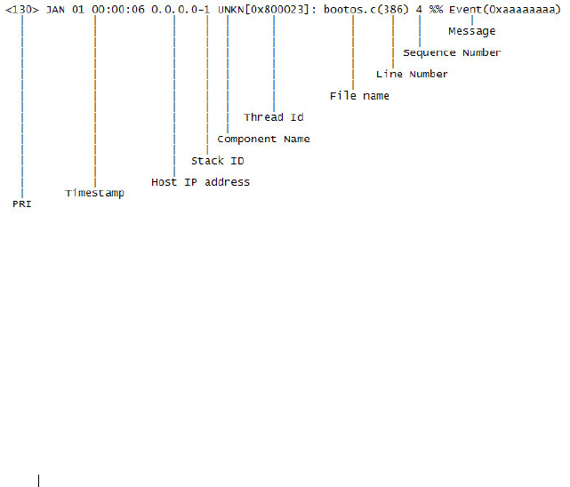
246 Monitoring and Logging System Information
To view the log messages in the system startup and operational log files, you
must download the log files to an administrative host. The startup log files are
named slogX.txt and the operation log files are named ologX.txt. When
enabled, the system stores the startup and operation log files for the last three
switch boots. The current log files have a zero (0) in the file name (replacing
the X in the name as shown above), the prior log files contain a one (1) in the
name, and the oldest log files contain a two (2) in the name. For more
information about downloading files, see "Managing Images and Files" on
page 359.
What Is the Log Message Format?
The first part of the log message up to the first left bracket is fixed by the
Syslog standard (RFC 3164). The second part up to the two percent signs is
standardized for all Dell Networking logs. The variable text of the log message
follows. The log message is limited to 96 bytes.
Each log message uses the following format:
• PRI—This consists of the facility code (see RFC 3164) multiplied by 8 and
added to the severity. The log messages use the local7 facility code (23).
This implies that a message of severity 0 will have a priority of 184 and a
message of severity 7 will have a priority of 191.
• Timestamp—This is the system up time. For systems that use SNTP, this
is UTC. When time zones are enabled, local time will be used.
• Host IP address—This is the IP address of the local system.

Monitoring and Logging System Information 247
• Stack ID —This is the assigned stack ID. For the Dell Networking N2000,
N3000, and N4000 series switches, the stack ID number is always 1. The
number 1 is used for systems without stacking ability. The top of stack is
used to collect messages for the entire stack.
• Component name—The component name for the logging component.
Component “UNKN” is substituted for components that do not identify
themselves to the logging component.
• Thread ID—The thread ID of the logging component.
• File name —The name of the file containing the invoking macro.
• Line number —The line number which contains the invoking macro.
• Sequence number —The message sequence number for this stack
component. Sequence numbers may be skipped because of filtering but
are always monotonically increasing on a per-stack member basis.
• Message — Contains the text of the log message.
What Factors Should Be Considered When Configuring Logging?
Dell recommends that network administrators deploy a syslog server in their
network and configure all switches to log messages to the syslog server. Switch
administrators should also consider enabling persistent logging on the switch.
When managing logs on a stack of switches, the RAM log and persistent log
files exist only on the top of stack platform. Other platforms in the stack
forward their messages to the top of stack log.

248 Monitoring and Logging System Information
Default Log Settings
System logging is enabled, and messages are sent to the console (severity
level: warning and above), and RAM log (severity level: informational and
above). Switch auditing, CLI command logging, Web logging, and SNMP
logging are disabled. By default, no messages are sent to the log file that is
stored in flash, and no remote log servers are defined.
Email alerting is disabled, and no recipient email address is configured.
Additionally, no mail server is defined. If you add a mail server, by default, no
authentication or security protocols are configured, and the switch uses TCP
port 25 for SMTP.
After you enable email alerting and configure the mail server and recipient
email address, log messages with a severity level of emergency and alert are
sent immediately with each log message in a separate mail. The email subject
is “Urgent Log Messages.” Log messages with a severity level of critical, error,
and warning are sent periodically in a single email. The email subject is “Non
Urgent Log Messages.” Messages with a severity level of notice and below are
not sent in an email.
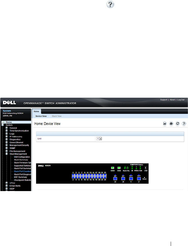
Monitoring and Logging System Information 249
Monitoring System Information and Configuring
Logging (Web)
This section provides information about the OpenManage Switch
Administrator pages to use to monitor system information and configure
logging on the Dell Networking N2000, N3000, and N4000 series switches.
For details about the fields on a page, click at the top of the page.
Device Information
The Device Information page displays after you successfully log on to the
switch by using the Dell OpenManage Switch Administrator. This page is a
virtual representation of the switch front panel. Use the Device Information
page to view information about the port status, or system status, and the
switch stack. Click on a port to access the Port Configuration page for the
selected port.
To display the Device Information page, click Home in the navigation panel.
Figure 11-1. Device Information
Click the Stack View link to view front panel representations for all units in
the stack.
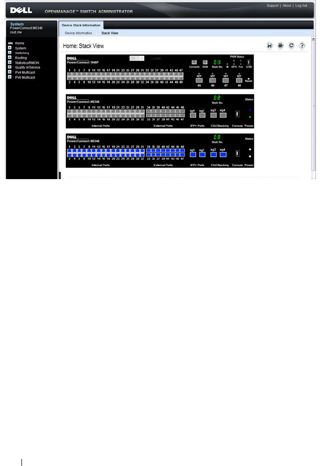
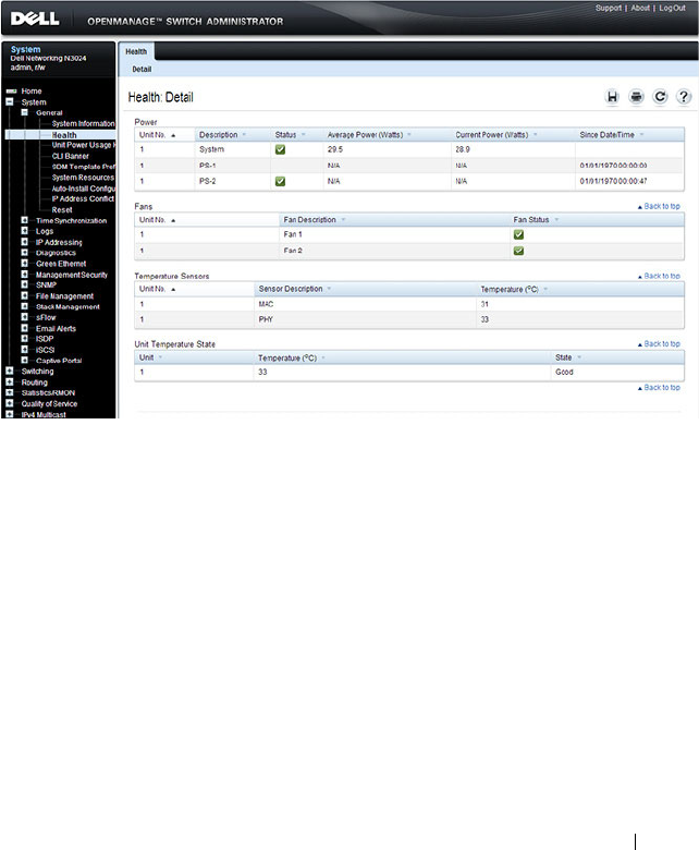
Monitoring and Logging System Information 251
System Health
Use the Health page to view status information about the switch power and
ventilation sources.
To display the Health page, click System
→
General
→
Health in the
navigation panel.
Figure 11-3. Health
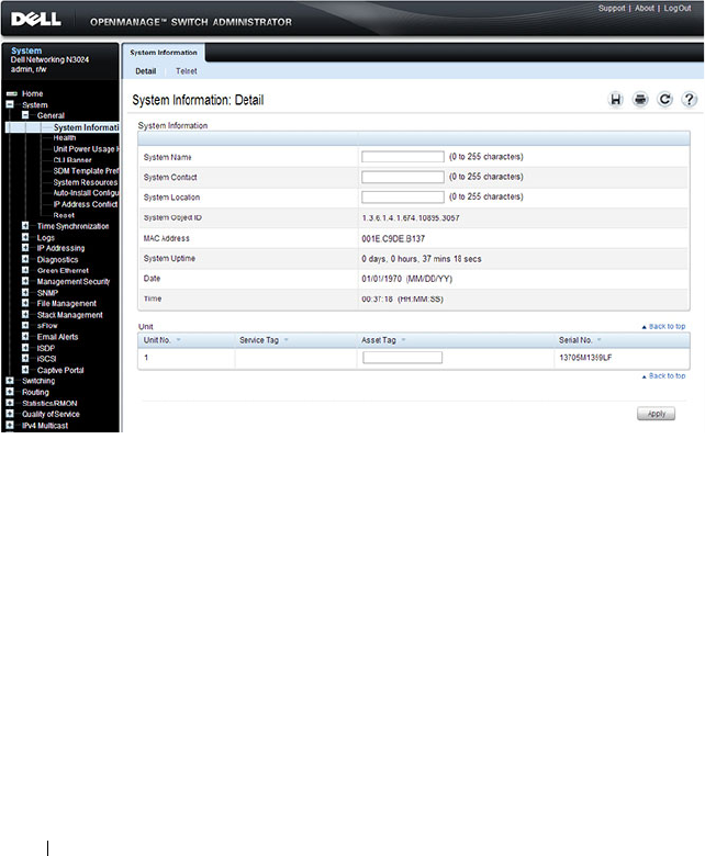
252 Monitoring and Logging System Information
System Resources
Use the System Resources page to view information about memory usage and
task utilization.
To display the System Resources page, click System
→
General
→
System
Resources in the navigation panel.
Figure 11-4. System Resources
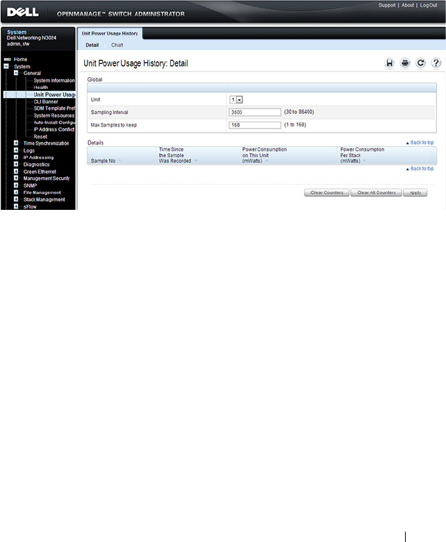
Monitoring and Logging System Information 253
Unit Power Usage History
Use the Unit Power Usage History page to view information about switch
power consumption.
To display the Unit Power Usage History page, click System
→
General
→
Unit Power Usage History in the navigation panel.
Figure 11-5. Unit Power Usage History
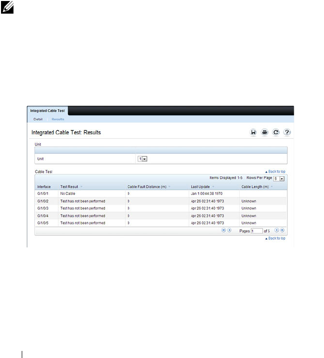
254 Monitoring and Logging System Information
Integrated Cable Test for Copper Cables
Use the Integrated Cable Test for Copper Cables page to perform tests on
copper cables. Cable testing provides information about where errors
occurred in the cable, the last time a cable test was performed, and the type of
cable error which occurred. The tests use Time Domain Reflectometry
(TDR) technology to test the quality and characteristics of a copper cable
attached to a port. Cables up to 120 meters long can be tested. Cables are
tested when the ports are in the down state, with the exception of the
Approximated Cable Length test. SFP, SFP+, and QSFP cables with passive
copper assemblies are not capable of performing TDR tests.
To display the Integrated Cable Test for Copper Cables page, click System
→
Diagnostics
→
Integrated Cable Test in the navigation panel.
Figure 11-6. Integrated Cable Test for Copper Cables
NOTE: Cable diagnostics may give misleading results if any green Ethernet
modes are enabled on the port. Disable EEE or energy-detect mode prior to
running any cable diagnostics.
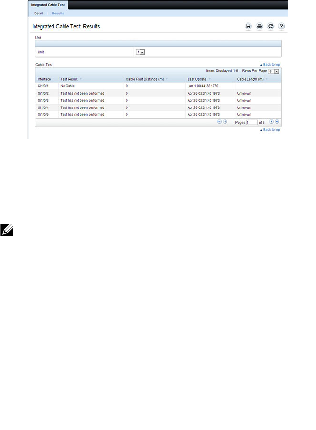
Monitoring and Logging System Information 255
To view a summary of all integrated cable tests performed, click the Show All
link.
Figure 11-7. Integrated Cable Test Summary
Optical Transceiver Diagnostics
Use the Transceiver Diagnostics page to perform tests on Fiber Optic cables.
To display the Transceiver Diagnostics page, click System
→
Diagnostics
→
Transceiver Diagnostics in the navigation panel.
NOTE: Optical transceiver diagnostics can be performed only when the link is
present.
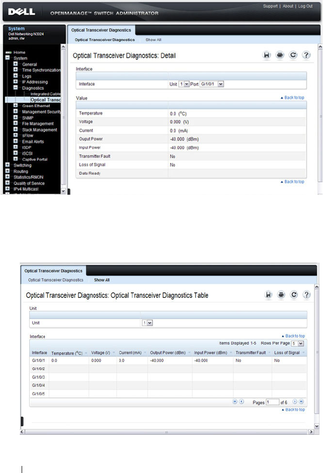
256 Monitoring and Logging System Information
Figure 11-8. Transceiver Diagnostics
To view a summary of all optical transceiver diagnostics tests performed, click
the Show All link.
Figure 11-9. Transceiver Diagnostics Summary
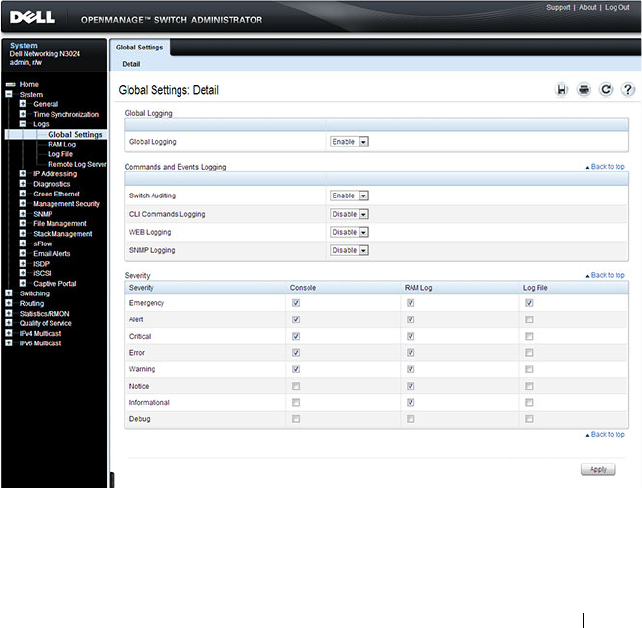
Monitoring and Logging System Information 257
Log Global Settings
Use the Global Settings page to enable logging globally, to enable other types
of logging. You can also specify the severity of messages that are logged to the
console, RAM log, and flash-based log file.
The Severity table lists log messages from the highest severity (Emergency) to
the lowest (Debug). When you select a severity level, all higher levels are
automatically selected. To prevent log messages from being sent to the
console, RAM log, or flash log file, clear all check boxes in the Severity
column.
To display the Global Settings page, click System
→
Logs
→
Global Settings
in the navigation panel.
Figure 11-10. Global Settings
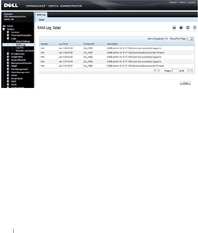
258 Monitoring and Logging System Information
RAM Log
Use the RAM Log page to view information about specific RAM (cache) log
entries, including the time the log was entered, the log severity, and a
description of the log.
To display the RAM Log, click System
→
Logs
→
RAM Log in the navigation
panel.
Figure 11-11. RAM Log Table

Monitoring and Logging System Information 259
Log File
The Log File contains information about specific log entries, including the
time the log was entered, the log severity, and a description of the log.
To display the Log File, click System
→
Logs
→
Log File in the navigation
panel.
Figure 11-12. Log File
Syslog Server
Use the Remote Log Server page to view and configure the available syslog
servers, to define new syslog servers, and to set the severity of the log events
sent to the syslog server.
To display the Remote Log Server page, click System
→
Logs
→
Remote Log
Server.
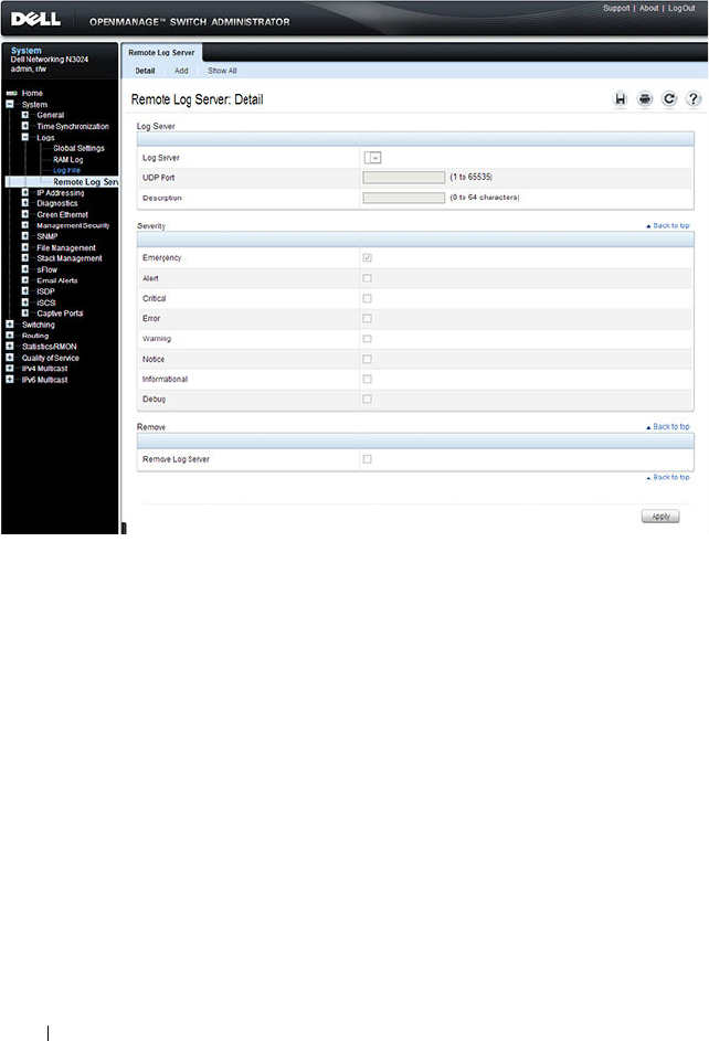
260 Monitoring and Logging System Information
Figure 11-13. Remote Log Server
Adding a New Remote Log Server
To add a syslog server:
1
Open the
Remote Log Server
page.
2
Click
Add
to display the
Add Remote Log Server
page.
3
Specify the IP address or hostname of the remote server.
4
Define the
UDP Port
and
Description
fields.
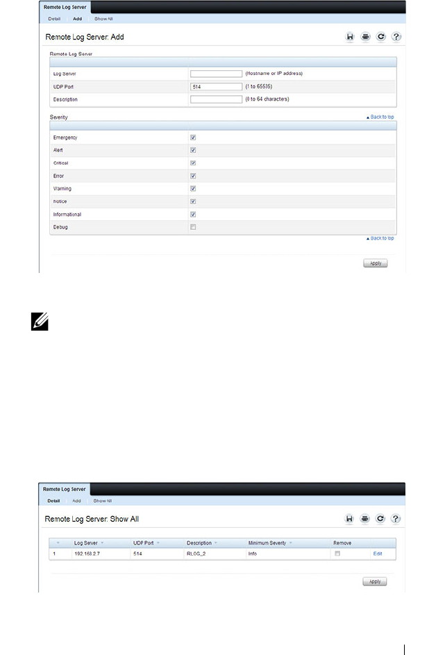
Monitoring and Logging System Information 261
Figure 11-14. Add Remote Log Server
5
Select the severity of the messages to send to the remote server.
6
Click
Apply
.
Click the Show All link to view or remove remote log servers configured on
the system.
Figure 11-15. Show All Log Servers
NOTE: When you select a severity level, all higher (numerically lower)
severity levels are automatically selected.
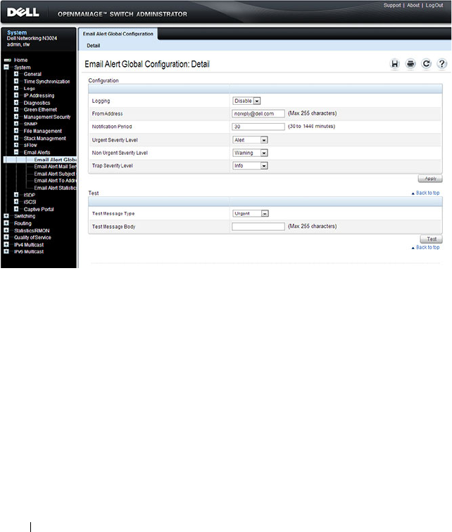
262 Monitoring and Logging System Information
Email Alert Global Configuration
Use the Email Alert Global Configuration page to enable the email alerting
feature and configure global settings so that system log messages can be sent
to from the switch to one or more email accounts.
To display the Email Alert Global Configuration page, click System
→
Email Alerts
→
Email Alert Global Configuration in the navigation panel.
Figure 11-16. Email Alert Global Configuration
Email Alert Mail Server Configuration
Use the Email Alert Mail Server Configuration page to configure
information about the mail server the switch uses for sending email alert
messages.
To display the Email Alert Mail Server Configuration page, click System
→
Email Alerts
→
Email Alert Mail Server Configuration in the navigation
panel.
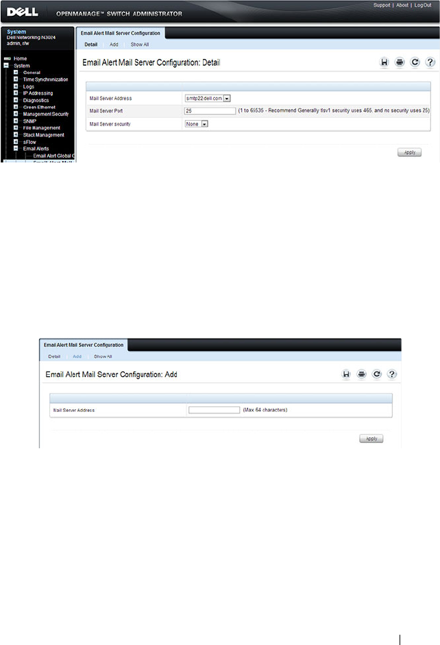
Monitoring and Logging System Information 263
Figure 11-17. Email Alert Mail Server Configuration
Adding a Mail Server
To add a mail server:
1
Open the
Email Alert Mail Server Configuration
page.
2
Click
Add
to display the
Email Alert Mail Server Add
page.
3
Specify the hostname of the mail server.
Figure 11-18. Add Mail Server
4
Click
Apply
.
5
If desired, click
Configuration
to return to the
Email Alert Mail Server
Configuration
page to specify port and security settings for the mail server.
Click the Show All link to view or remove mail servers configured on the
switch.
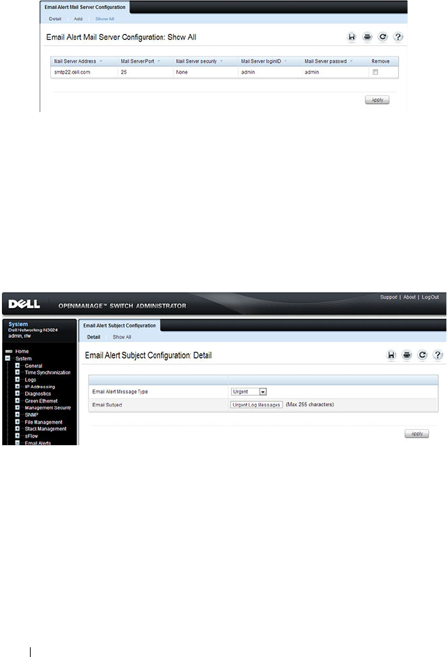
264 Monitoring and Logging System Information
Figure 11-19. Show All Mali Servers
Email Alert Subject Configuration
Use the Email Alert Subject Configuration page to configure the subject line
for email alerts that are sent by the switch. You can customize the subject for
the message severity and entry status.
To display the Email Alert Subject Configuration page, click System
→
Email Alerts
→
Email Alert Subject Configuration in the navigation panel.
Figure 11-20. Email Alert Subject Configuration
To view all configured email alert subjects, click the Show All link.
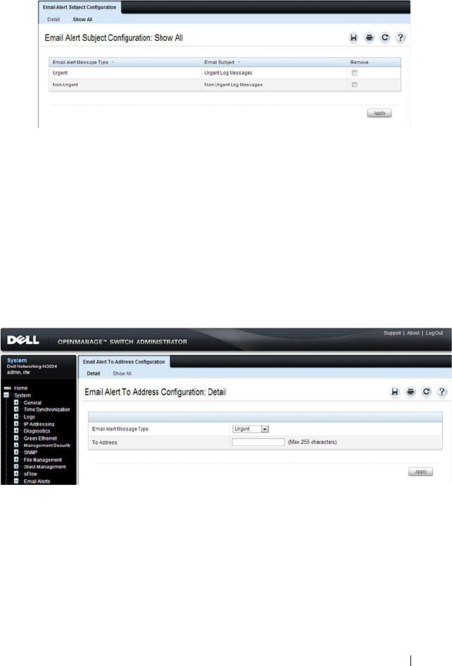
Monitoring and Logging System Information 265
Figure 11-21. View Email Alert Subjects
Email Alert To Address Configuration
Use the Email Alert To Address Configuration page to specify where the
email alerts are sent. You can configure multiple recipients and associate
different message severity levels with different recipient addresses.
To display the Email Alert To Address Configuration page, click System
→
Email Alerts
→
Email Alert To Address Configuration in the navigation
panel.
Figure 11-22. Email Alert To Address Configuration
To view configured recipients, click the Show All link.
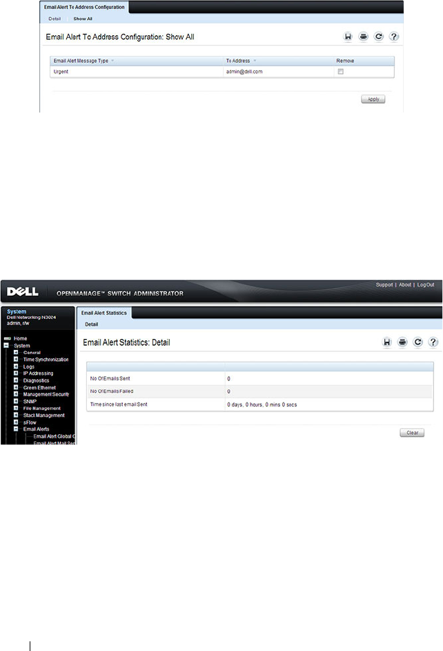
266 Monitoring and Logging System Information
Figure 11-23. View Email Alert To Address Configuration
Email Alert Statistics
Use the Email Alert Statistics page to view the number of emails that were
successfully and unsuccessfully sent, and when emails were sent.
To display the Email Alert Statistics page, click System
→
Email Alerts
→
Email Alert Statistics in the navigation panel.
Figure 11-24. Email Alert Statistics

Monitoring and Logging System Information 267
Monitoring System Information and Configuring
Logging (CLI)
This section provides information about the commands you use to configure
information you use to monitor the Dell Networking N2000, N3000, and
N4000 series switches. For more information about these commands, see the
Dell Networking N2000, N3000, and N4000 Series Switches CLI Reference
Guide
at support.dell.com/manuals.
Viewing System Information and Enabling the Locator LED
Beginning in Privileged EXEC mode, use the following commands to view
system health and resource information and to enable the switch locator
LED.
Command Purpose
show system Display various system information.
show system power Displays the power supply status.
show system
temperature
Displays the system temperature and fan status.
show memory cpu Displays the total and available RAM space on the switch.
show process cpu Displays the CPU utilization for each process currently
running on the switch.
locate [switch
unit
]
[time
time
]
Enable the switch locator LED located on the back panel
of the switch. Optionally, you can specify the unit to
identify within a switch stack and the length of time that
the LED blinks.
Command Purpose
show system Display various system information.
show system power Displays the power supply status.
show system
temperature
Displays the system temperature and fan status.
show memory cpu Displays the total and available RAM space on the switch.

268 Monitoring and Logging System Information
Running Cable Diagnostics
Beginning in Privileged EXEC mode, use the following commands to run the
cable diagnostic tests.
show process cpu Displays the CPU utilization for each process currently
running on the switch.
NOTE: Cable diagnostics may give misleading results if green mode is enabled
on the port. Disable green mode prior to running any cable diagnostics.
Command Purpose
test copper-port tdr
interface
Perform the Time Domain Reflectometry (TDR) test to
diagnose the quality and characteristics of a copper cable
attached to the specified port. SFP, SFP+, and QSFP
cables with passive copper assemblies are not capable of
performing TDR tests.
CAUTION: Issuing the test copper-port tdr command
will bring the interface down.
NOTE: To ensure accurate measurements, disable all Green
Ethernet modes (EEE or energy-detect mode) on the port
before running the test.
The interface is specified in unit/slot/port format. For
example 1/0/3 is GbE interface 3 on unit 1 of the stack.
show copper-ports tdr
[
interface
]
Display the diagnostic information collected by the test
copper-port tdr command for all copper interfaces or a
specific interface.
show fiber-ports optical-
transceiver [
interface
]
Display the optical transceiver diagnostics for all fiber
ports. Include the
interface
option to show information for
the specified port.
Command Purpose

Monitoring and Logging System Information 269
Configuring Local Logging
Beginning in Privileged EXEC mode, use the following commands to
configure the type of messages that are logged and where the messages are
logged locally.
Command Purpose
configure Enter Global Configuration mode.
logging on Globally enables logging.
logging audit Enable switch auditing.
logging cli-command Enable CLI command logging
logging web-sessions Enable logging of the switch management Web page visits.
logging snmp Enable logging of SNMP set commands.
terminal monitor Enable display of system messages on the console for
Telnet/SSH sessions.
logging
{buffered|console| file}
[
severity
]
Enable logging to the specified file. Optionally, you can
define a logging discriminator to help filter log messages
and set the severity of the messages to log.
•
buffered
— Enables logging to the RAM file (cache). If
the switch resets, the buffered logs are cleared.
•
console
— Enables logging to the screen when you are
connected to the CLI through the console port.
•
file
— Enables logging to the startup and operational log
files on the flash.
•
discriminator
disc-name
— (Optional) Include a
message discriminator to help filter log messages. The
disc-name
can contain up to eight alphanumeric
characters. Spaces are not permitted.
•
severity
— (Optional) Enter the number or name of the
desired severity level. For information about severity
levels, see Table 11-1.
logging facility
facility-
type
Set the facility for logging messages. Permitted
facility-
type
values are local0, local1, local2, local3, local4, local5,
local 6, local7
CTRL + Z Exit to Privileged EXEC mode.

270 Monitoring and Logging System Information
Configuring Remote Logging
Beginning in Privileged EXEC mode, use the following commands to define a
remote server to which the switch sends log messages.
show logging Displays the state of logging and the syslog messages
stored in the internal buffer.
show logging file View information about the flash (persistent) log file.
clear logging Use to clear messages from the logging buffer.
Command Purpose
configure Enter Global Configuration mode.
logging {
ip-address
|
hostname
}
Define a remote log server and enter the configuration
mode for the specified log server.
description
description
Describe the log server. Use up to 64 characters. If the
description includes spaces, surround it with quotation
marks.
level
severity
Specify the severity level of the logs that should be sent to
the remote log server. For information about severity
levels, see Table 11-1.
port
udp-port
Specify the UDP port to use for sending log messages. The
range is 1 to 65535, and the default is 514.
CTRL + Z Exit to Privileged EXEC mode.
show syslog-servers Verify the remote log server configuration.
Command Purpose

Monitoring and Logging System Information 271
Configuring Mail Server Settings
Beginning in Privileged EXEC mode, use the following commands to
configure information about the mail server (SMTP host) on the network
that will initially receive the email alerts from the switch and relay them to
the correct recipient.
Command Purpose
configure Enter Global Configuration mode.
mail-server
ip-address
Specify the IP address of the SMTP server on the network
and enter the configuration mode for the mail server.
security {tlsvl|none} (Optional) Specify the security protocol to use with the
mail server.
port {25|465} Configure the TCP port to use for SMTP, which can be 25
(SMTP) or 465 (SMTP over SSL).
username
username
If the SMTP server requires authentication, specify the
username to use for the switch.
The same username and password settings must be
configured on the SMTP host.
password
password
If the SMTP server requires authentication from clients,
specify the password to associate with the switch
username.
CTRL + Z Exit to Privileged EXEC mode.
show mail-server all
config
View mail server configuration information for all
configured mail servers.

272 Monitoring and Logging System Information
Configuring Email Alerts for Log Messages
Beginning in Privileged EXEC mode, use the following commands to
configure email alerts so that log messages are sent to the specified address.
Command Purpose
configure Enter Global Configuration mode.
logging email [
severity
] Enable email alerting and determine which non-critical log
messages should be emailed. Including the
severity
value
sets the lowest severity for which log messages are emailed.
These messages are collected and sent in a single email at
the configured log duration.
severity
— (Optional) Enter the number or name of the
severity level for non-critical messages. Log messages at or
above this severity level are emailed. For information about
severity levels, see Table 11-1. Log messages below the
specified level are not emailed.
logging email urgent
{
severity
| none}
Determine which log messages are critical and should be
sent in a single email as soon as they are generated.
severity
— (Optional) Enter the number or name of the
severity level for critical messages. For information about
severity levels, see Table 11-1.
logging email logtime
minutes
Specify how often to send the non-critical email alerts that
have been collected. . The valid range is 30 - 1440 minutes.
logging email message-
type {urgent | non-
urgent | both} to-addr
email-address
Specify the email address of the recipient for log messages.
logging email from-addr
email-address
Specify the email address of the sender, which is the
switch.
logging email message-
type {urgent | non-
urgent | both} subject
subject
Specify the text that will appear in the subject line of email
alerts sent by the switch.

Monitoring and Logging System Information 273
logging email test
message-type {urgent |
non-urgent | both}
message-body
body
Send a test email to the configured recipient to verify that
the feature is properly configured.
CTRL + Z Exit to Privileged EXEC mode.
show logging email
config
View the configured settings for email alerts.
show logging email
statistics
View information about the number of emails sent and the
time they were sent.
clear logging email
statistics
Clear the email alerting statistics.
Command Purpose

274 Monitoring and Logging System Information
Logging Configuration Examples
This section contains the following examples:
• Configuring Local and Remote Logging
• Configuring Email Alerting
Configuring Local and Remote Logging
This example shows how to enable switch auditing and CLI command
logging. Log messages with a severity level of Notification (level 5) and above
are sent to the RAM (buffered) log. Emergency, Critical, and Alert (level 2)
log messages are written to the log file on the flash drive. All log messages are
displayed on the console and sent to a remote syslog server.
To configure the switch:
1
Enable switch auditing and CLI command logging.
console#configure
console(config)#logging audit
console(config)#logging cli-command
2
Specify where the logs are sent locally and what severity level of message is
to be logged. You can specify the severity as the level number, as shown in
the first two commands, or as the keyword, shown in the third command.
console(config)#logging buffered 5
console(config)#logging file 2
console(config)#logging console debugging
3
Define the remote log server.
console(config)#logging 192.168.2.10
console(Config-logging)#description "Syslog
Server"
console(Config-logging)#level debug
console(Config-logging)#exit
console(config)#exit

Monitoring and Logging System Information 275
4
Verify the remote log server configuration.
console#show syslog-servers
IP Address/Hostname Port Severity Description
------------------------- ------ -------------- ----------
192.168.2.10 514 debugging Syslog Server
5
Verify the local logging configuration and view the log messages stored in
the buffer (RAM log).
console#show logging
Logging is enabled
Console Logging: level debugging. Console
Messages: 748 Dropped.
Buffer Logging: level notifications. Buffer
Messages: 79 Logged,
File Logging: level critical. File Messages: 973
Dropped.
CLI Command Logging : enabled
Switch Auditing : enabled
Web Session Logging : disabled
SNMP Set Command Logging : disabled
Syslog server 192.168.2.10 logging: debug.
Messages: 0 dropped
412 Messages dropped due to lack of resources.
Buffer Log:
<186> FEB 02 05:53:03 0.0.0.0-1 UNKN[1073741088]:
bootos.c(232) 1 %% Event(0xaaaaaaaa)
<189> FEB 02 05:53:03 0.0.0.0-1 UNKN[1073741088]:
bootos.c(248) 2 %% Starting code... BSP
initialization complete, starting application.
--More-- or (q)uit
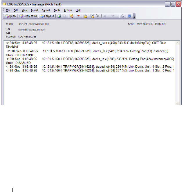
276 Monitoring and Logging System Information
Configuring Email Alerting
The commands in this example define the SMTP server to use for sending
email alerts. The mail server does not require authentication and uses the
standard TCP port for SMTP, port 25, which are the default values. Only
Emergency messages (severity level 0) will be sent immediately as individual
emails, and messages with a severity of alert, critical, and error (levels 1-3) will
be sent in a single email every 120 minutes. Warning, notice, info, and debug
messages are not sent in an email.
The email the administrator will in the inbox has a format similar to the
following:
Figure 11-25. Email Alert Message Format
For emergency-level messages, the subject is LOG MESSAGE -
EMERGENCY. For messages with a severity level of alert, critical, and error,
the subject is LOG MESSAGE.
To configure the switch:
1
Specify the mail server to use for sending messages.
console#configure
console(config)#mail-server ip-address 192.168.2.34

Monitoring and Logging System Information 277
2
Configure the username and password that the switch must use to
authenticate with the mail server.
console(Mail-Server)#username switchN3048
console(Mail-Server)#password passwordN3048
console(Mail-Server)#exit
3
Configure emergencies and alerts to be sent immediately, and all other
messages to be sent in a single email every 120 minutes.
console(config)#logging email error
console(config)#logging email urgent emergency
console(config)#logging email logtime 120
4
Specify the email address of the sender (the switch).
console(config)#logging email from-addr
N3048_noreply@dell.com
5
Specify the address where email alerts should be sent.
console(config)#logging email message-type both
to-addr administrator@dell.com
6
Specify the text that will appear in the email alert Subject line.
console(config)#logging email message-type urgent
subject "LOG MESSAGES - EMERGENCY"
console(config)#logging email message-type non-
urgent subject "LOG MESSAGES"
7
Verify the configuration.
console#show mail-server all config
Mail Servers Configuration:
No of mail servers configured.................. 1
Email Alert Mail Server Address................ 192.168.2.34
Email Alert Mail Server Port................... 25
Email Alert SecurityProtocol................... none
Email Alert Username........................... switchN3048
Email Alert Password........................... passwordN3048
console#show logging email config

278 Monitoring and Logging System Information
Email Alert Logging............................ enabled
Email Alert From Address.......................
N3048_noreply@dell.com
Email Alert Urgent Severity Level.............. 0
Email Alert Non Urgent Severity Level.......... 3
Email Alert Trap Severity Level................ 6
Email Alert Notification Period................ 120 min
Email Alert To Address Table:
For Msg Type..........................1
Address1..............................administrator@dell.com
For Msg Type..........................2
Address1..............................administrator@dell.com
Email Alert Subject Table :
For Msg Type 1, subject is............LOG MESSAGES - EMERGENCY
For Msg Type 2, subject is............LOG MESSAGE

Managing General System Settings 279
12
Managing General System Settings
This chapter describes how to set system information, such as the hostname,
and time settings, and how to select the Switch Database Management
(SDM) template to use on the switch.
For the N2000 and N3000 series switches, this chapter also describes how to
configure the Power over Ethernet (PoE) settings.
For the N3000 series switches, this chapter also describes how to view back-
panel expansion slot information.
The topics covered in this chapter include:
• System Settings Overview
• Default General System Information
• Configuring General System Settings (Web)
• Configuring System Settings (CLI)
• General System Settings Configuration Examples
System Settings Overview
The system settings include the information described in Table 12-1. This
information helps identify the switch.
Table 12-1. System Information
Feature Description
System Name The switch name (host name). If you change the system name,
the CLI prompt changes from console to the system name.
System contact Identifies the person to contact for information regarding the
switch.
System location Identifies the physical location of the switch.
Asset tag Uniquely identifies the switch. Some organizations use asset tags
to identify, control, and track each piece of equipment.

280 Managing General System Settings
The switch can obtain the time from a Simple Network Time Protocol
(SNTP) server, or you can set the time manually. Table 12-2 describes the
settings that help the switch keep track of time.
The Dell Networking N2024P/N2048P and N3024P/N3048P switch ports are
IEEE 802.1at-2009-compliant (PoE Plus) and can provided up to 34.2W of
power per port. For more information about PoE Plus support, see "What Are
the Key PoE Plus Features for the N2024P/N2048P and N3024P/N3048P
Switches?" on page 285
CLI Banner Displays a message upon connecting to the switch or logging on
to the switch by using the CLI.
SDM Template Determines the maximum resources a switch or router can use
for various features. For more information, see "What Are SDM
Templates?" on page 281
Table 12-2. Time Settings
Feature Description
SNTP Controls whether the switch obtains its system time
from an SNTP server and whether communication
with the SNTP server requires authentication and
encryption. You can configure information for up to
eight SNTP servers. The SNTP client on the switch can
accept updates from both IPv4 and IPv6 SNTP servers.
Real time clock (RTC) If SNTP is disabled, you can manually enter the system
time and date.
Time Zone Allows you to specify the offset from Coordinated
Universal Time (UTC), which is also known as
Greenwich Mean Time (GMT).
Summer Time In some regions, the time shifts by one hour in the fall
and spring. In the United States, this is called daylight
saving time.
Table 12-1. System Information (Continued)
Feature Description

Managing General System Settings 281
Why Does System Information Need to Be Configured?
Configuring system information is optional. However, it can be helpful in
providing administrative information about the switch. For example, if you
manage several standalone Dell Networking series switches and have Telnet
sessions open with several different switches, the system name can help you
quickly identify the switch because the host name replaces console as the
CLI command prompt.
The Banner can provide information about the switch status. For example, if
multiple users connect to the switch, the message of the day (MOTD) banner
might alert everyone who connects to the switch about a scheduled switch
image upgrade.
What Are SDM Templates?
An SDM template is a description of the maximum resources a switch or
router can use for various features. Different SDM templates allow different
combinations of scaling factors, enabling different allocations of resources
depending on how the device is used. In other words, SDM templates enable
you to reallocate system resources to support a different mix of features based
on your network requirements.
Dell Networking series switches support the following three templates:
• Dual IPv4 and IPv6 (default)
•IPv4 Routing
•IPv4 Data Center
Table 12-3 describes the parameters that are scaled for each template and the
per-template maximum value of the parameter.
Table 12-3. SDM Template Parameters and Values
Parameter Dual IPv4/IPv6 Dual IPv4/IPv6
Data Center
IPv4 Only IPv4 Data
Center
ARP entries
N2000
N3000
N4000
1024
4096
4096
0
4096
4096
1024
6144
6144
0
0
4096

282 Managing General System Settings
IPv4 unicast routes
N2000
N3000
N4000
256
8160
8160
0
8160
8160
512
12288
12288
0
0
8160
IPv6 Neighbor
Discovery Protocol
(NDP) entries
N2000
N3000
N4000
512
2560
1024
0
2560
1024
0
0
0
0
0
0
IPv6 unicast routes
N2000
N3000
N4000
128
4096
4096
0
4096
4096
0
0
0
0
0
0
ECMP next hops
N2000
N3000
N4000
1
4
4
0
16
4
1
16
16
0
0
16
IPv4 multicast routes
N2000
N3000
N4000
0
1536
512
0
1536
512
0
2048
1024
0
0
2048
IPv6 multicast routes
N2000
N3000
N4000
0
512
256
0
512
256
0
0
0
0
0
0
Table 12-3. SDM Template Parameters and Values (Continued)
Parameter Dual IPv4/IPv6 Dual IPv4/IPv6
Data Center
IPv4 Only IPv4 Data
Center

Managing General System Settings 283
SDM Template Configuration Guidelines
When you configure the switch to use an SDM template that is not currently
in use, you must reload the switch for the configuration to take effect.
If the IPv4 Routing or IPv4 Data Center template is currently in use and you
attempt to configure IPv6 routing features without first selecting the Dual
IPv4-IPv6 Routing template, the IPv6 commands do not take effect. IPv6
features are not available when an IPv4-only template is active.
Why is the System Time Needed?
The switch uses the system clock to provide time stamps on log messages.
Additionally, some show commands include the time in the command
output. For example, the show users login-history command includes a Login
Time field. The system clock provides the information for the Login Time
field.
How Does SNTP Work?
SNTP assures accurate switch clock time synchronization. Time
synchronization is performed by a network SNTP server.
Time sources are established by Stratums. Stratums define the accuracy of
the reference clock. The higher the stratum (where zero is the highest), the
more accurate the clock. The switch is at a stratum that is one lower than its
time source. For example, if the SNTP server in an internal network is a
Stratum 3 device, the switch is a Stratum 4 device.
You can configure the switch to request the time from an SNTP server on the
network, or you can allow the switch to receive SNTP broadcasts.
Requesting the time from a unicast SNTP server is more secure. Use this
method if you know the IP address of the SNTP server on your network. If you
allow the switch to receive SNTP broadcasts, any clock synchronization
information is accepted, even if it has not been requested by the device. This
method is less secure than polling a specified SNTP server.
NOTE: If you attach a unit to a stack and its template does not match the stack's
template, then the new unit will automatically reboot using the template used by
the management unit. To avoid the automatic reboot, you may first set the
template to the template used by the management unit. Then power off the new
unit, attach it to the stack, and power it on.

284 Managing General System Settings
To increase security, you can require authentication between the configured
SNTP server and the SNTP client on the switch. Authentication is provided
by Message Digest 5 (MD5). MD5 verifies the integrity of the
communication and authenticates the origin of the communication.
What Configuration Is Required for Plug-In Modules?
The N3000/N4000 series switches support several different plug-in modules
(also known as cards) for the expansion slots located on the back of the
switch. For information about the slots and the supported modules, see
"Hardware Overview" on page 91. You can preconfigure the card type prior to
inserting it into the switch.
Hot-swap is supported on the N3000/N4000 switch modules. However, the
switch must be rebooted for the new module to be recognized after it is
inserted.
Before inserting a new module into the expansion slot that was previously
occupied by a different type of module, issue a no slot command from the
CLI so that the switch can recognize the new module.
Once a module hs been recognized by the switch, its configuration is stored
locally on the switch as the switch default. The module configuration appears
in the running-config for informational purposes.

Managing General System Settings 285
What Are the Key PoE Plus Features for the N2024P/N2048P and
N3024P/N3048P Switches?
Table 12-4 describes some of the key PoE Plus features the switches support.
Table 12-4. PoE Plus Key Features
Feature Description
Global Usage
Threshold
Provides the ability to specify a power limit as a percentage
of the maximum power available to PoE ports. Setting a
limit prevents the PoE switch from reaching an overload
condition.
Per-Port Power
Prioritization
Provides the ability to assign a priority to each PoE port.
When the power budget of the PoE switch has been
exhausted, the higher-priority ports are given preference
over the lower-priority ports. Lower priority ports are
automatically stopped from supplying power in order to
provide power to higher-priority ports.
Per-Port Power Limit Configurable power limit for each PoE-Plus port.
Power Management
Modes
Supports two power-management modes:
• Static—Allows you to reserve a guaranteed amount of
power for a PoE port. This is useful for powering up devices
which draw variable amount of power and provide them an
assured power range to operate within.
• Dynamic—Power is not reserved for a given port at any
point of time. The power available with the PoE switch is
calculated by subtracting the instantaneous power drawn
by all the ports from the maximum available power. Thus
more ports can be powered at the same time. This feature
is useful to efficiently power up more number of devices
when the available power with the PoE switch is limited
Power Detection Mode Allows you to set the mode to legacy or 4-point 802.3AF
detection. Enabling an additional high-power setting will
allow the detection of 802.1at devices.

286 Managing General System Settings
Default General System Information
By default, no system information or time information is configured, and the
SNTP client is disabled. The default SDM Template applied to the switch is
the Dual IPv4-IPv6 template.
The following table shows the default PoE Plus settings for the Dell
Networking N2024P /N2048P and N3024P/N3048P switches.
Powered Device (PD)
Disconnection
Detection Mode
Configurable setting to set the method that determines
when a PD has disconnected from a port:
• AC Disconnect—Assumes that when a valid PD is
connected to a port, the AC impedance measured on its
terminals is significantly lower than in the case of an open
port (disconnected PD)
• DC Disconnect—Measures current consumption to
determine when a PD stops consuming current.
Table 12-5. PoE Plus Key Features (N2024P, N2048P, N3024P, N3048P Only)
Feature Description
Global Usage Threshold 0%
Per-Port Admin Status Auto
Per-Port Power Prioritization Enabled (globally, per-port priority is Low
Per-Port Power Limit None
Power Management Mode Dynamic
Power Detection Mode 802.3af Only
Powered Device (PD) Disconnection
Detection Mode
AC
Power Pairs alternative-a
Table 12-4. PoE Plus Key Features (Continued)
Feature Description
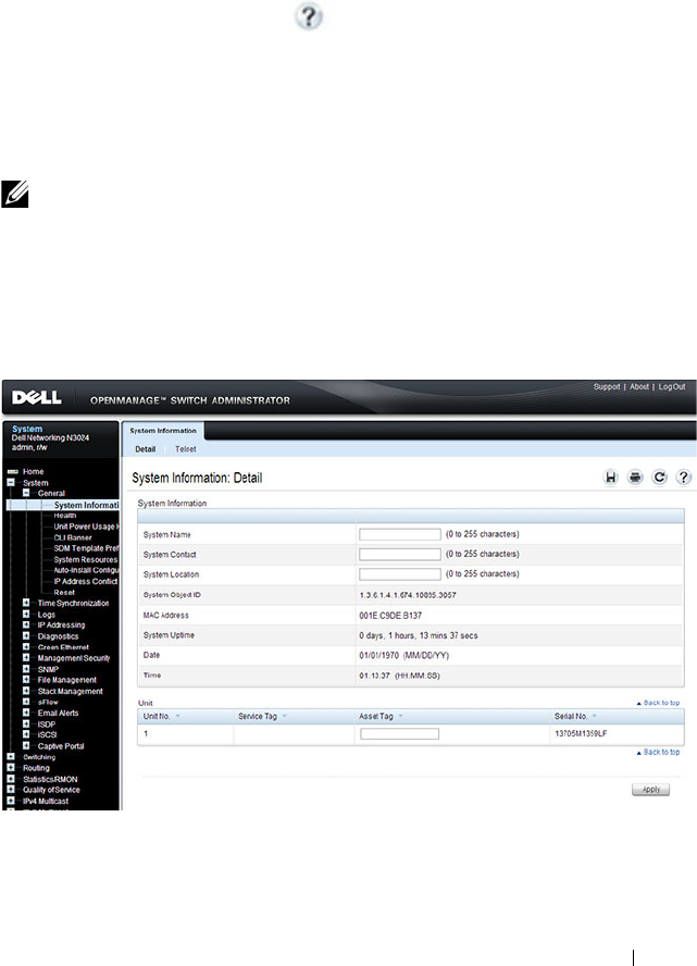
Managing General System Settings 287
Configuring General System Settings (Web)
This section provides information about the OpenManage Switch
Administrator pages for configuring and monitoring general system settings
on the Dell Networking N2000, N3000, and N4000 series switches. For details
about the fields on a page, click at the top of the page.
System Information
Use the System Information page to configure the system name, contact
name, location, and asset tag.
To display the System Information page, click System
→
General
→
System
Information in the navigation panel.
Figure 12-1. System Information
NOTE: From the System Information page, you can also initiate a Telnet session
to the switch.
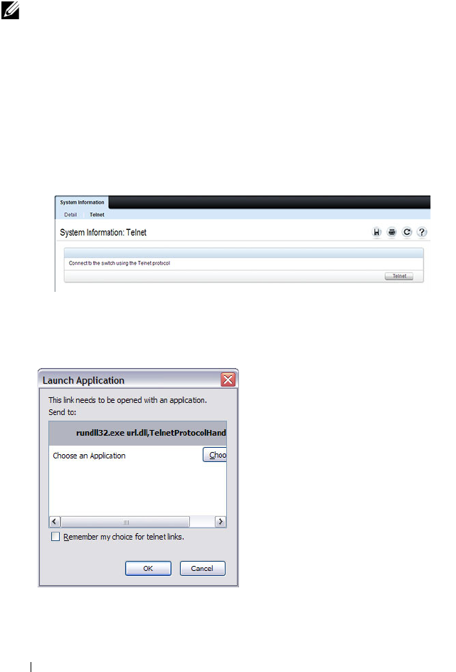
288 Managing General System Settings
Initiating a Telnet Session from the Web Interface
To launch a Telnet session:
1
From the
System
→
General
→
System Information
page, click the
Telnet link.
2
Click the
Telnet
button.
Figure 12-2. Telnet
3
Select the Telnet client, and click
OK
.
Figure 12-3. Select Telnet Client
NOTE: The Telnet client feature does not work with Microsoft Windows Internet
Explorer 7 and later versions. Initiating this feature from any browser running on
a Linux operating system is not supported.
Managing General System Settings 289
The selected Telnet client launches and connects to the switch CLI.
Figure 12-4. Telnet Session
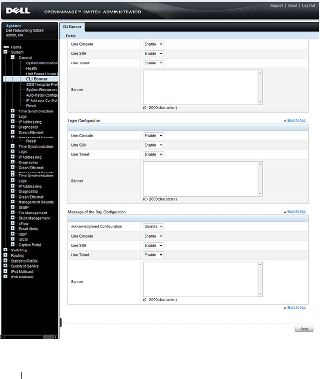
290 Managing General System Settings
CLI Banner
Use the CLI Banner page to configure a message for the switch to display
when a user connects to the switch by using the CLI. You can configure
different banners for various CLI modes and access methods.
To display the CLI Banner page, click System
→
General
→
CLI Banner in
the navigation panel.
Figure 12-5. CLI Banner
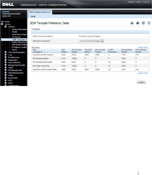
Managing General System Settings 291
SDM Template Preference
Use the SDM Template Preference page to view information about template
resource settings and to select the template that the switch uses. If you select
a new SDM template for the switch to use, you must reboot the switch before
the template is applied.
To display the SDM Template Preference page, click System
→
General
→
SDM Template Preference in the navigation panel.
Figure 12-6. SDM Template Preference
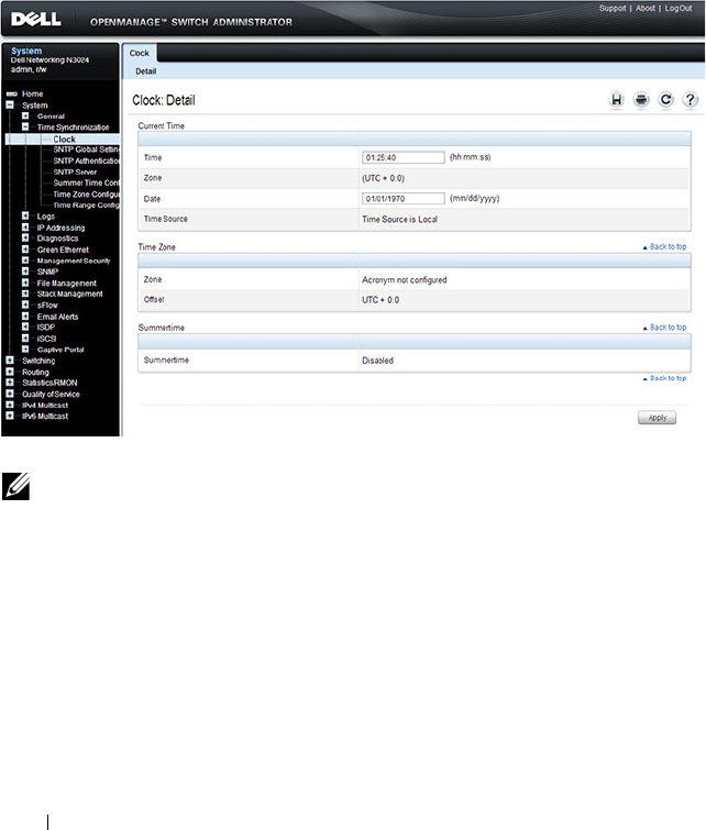
292 Managing General System Settings
Clock
If you do not obtain the system time from an SNTP server, you can manually
set the date and time on the switch on the Clock page. The Clock page also
displays information about the time settings configured on the switch.
To display the Clock page, click System
→
Time Synchronization
→
Clock
in the navigation panel.
Figure 12-7. Clock
NOTE: The system time cannot be set manually if the SNTP client is enabled. Use
the SNTP Global Settings page to enable or disable the SNTP client.
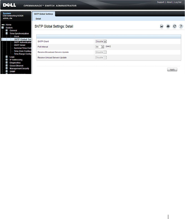
Managing General System Settings 293
SNTP Global Settings
Use the SNTP Global Settings
page
to enable or disable the SNTP client,
configure whether and how often the client sends SNTP requests, and
determine whether the switch can receive SNTP broadcasts.
To display the SNTP Global Settings
page, click System
→
Time
Synchronization
→
SNTP Global Settings in the navigation panel.
Figure 12-8. SNTP Global Settings
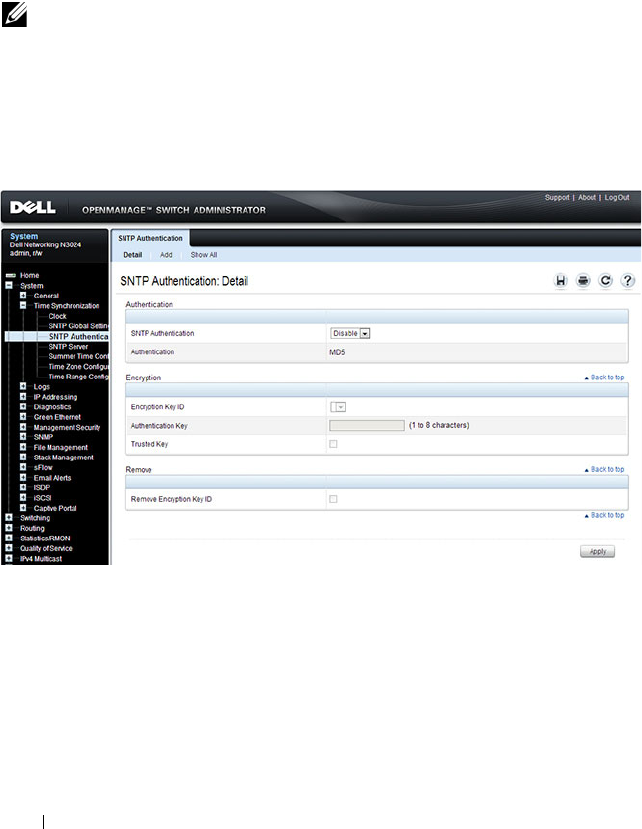
294 Managing General System Settings
SNTP Authentication
Use the SNTP Authentication page to enable or disable SNTP
authentication, to modify the authentication key for a selected encryption key
ID, to designate the selected authentication key as a trusted key, and to
remove the selected encryption key ID.
Click System
→
Time Synchronization
→
SNTP Authentication in the
navigation panel to display the SNTP Authentication page.
Figure 12-9. SNTP Authentication
Adding an SNTP Authentication Key
To configure SNTP authentication:
1
Open the
SNTP Authentication
page.
2
Click the
Add
link.
The
Add Authentication Key
page displays:
NOTE: The SNTP server must be configured with the same authentication
information to allow time synchronization to take place between the two devices.
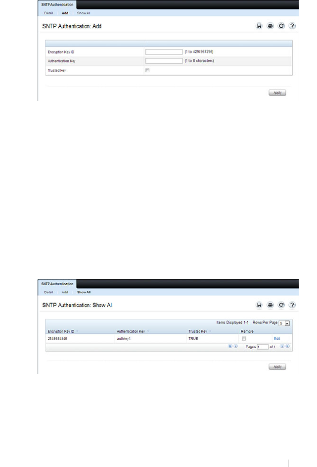
Managing General System Settings 295
Figure 12-10. Add Authentication Key
3
Enter a numerical encryption key ID and an authentication key in the
appropriate fields.
4
If the key is to be used to authenticate a unicast SNTP server, select the
Trusted Key
check box. If the check box is clear, the key is untrusted and
cannot be used for authentication.
5
Click
Apply
.
The SNTP authentication key is added, and the device is updated.
To view all configured authentication keys, click the Show All link. The
Authentication Key Table displays. You can also use the Authentication Key
Table to remove or edit existing keys.
Figure 12-11. Authentication Key Table
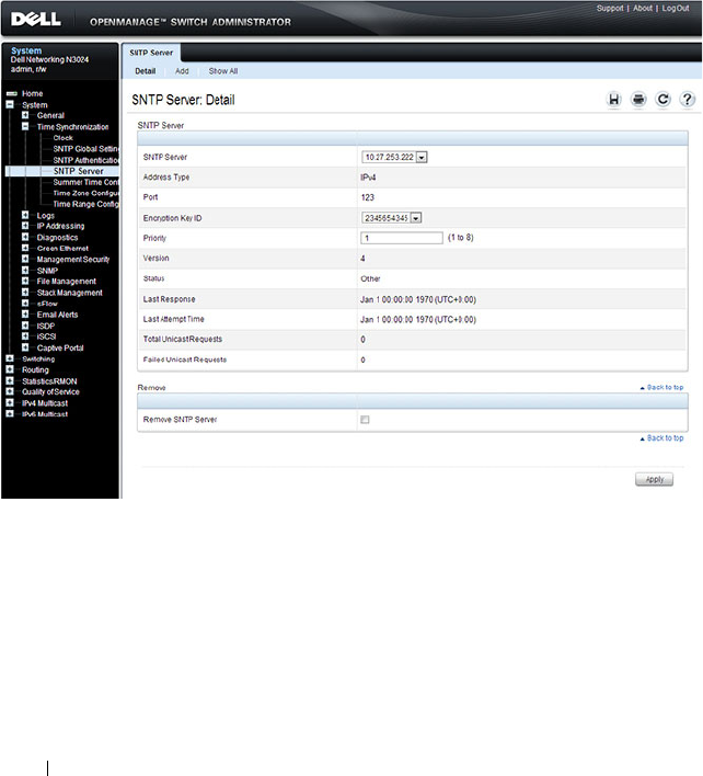
296 Managing General System Settings
SNTP Server
Use the SNTP Server
page
to view and modify information about SNTP
servers, and to add new SNTP servers that the switch can use for time
synchronization. The switch can accept time information from both IPv4 and
IPv6 SNTP servers.
To display the SNTP Server
page, click System
→
Time Synchronization
→
SNTP Server in the navigation panel. If no servers have been configured, the
fields in the following image are not displayed.
Figure 12-12. SNTP Servers
Defining a New SNTP Server
To add an SNTP server:
1
Open the
SNTP Servers
page.
2
Click
Add
.
The
Add SNTP Server
page displays.

Managing General System Settings 297
Figure 12-13. Add SNTP Server
3
In the
SNTP Server
field, enter the IP address or host name for the new
SNTP server.
4
Specify whether the information entered in the
SNTP Server
field is an
IPv4 address, IPv6 address, or a hostname (DNS).
5
If you require authentication between the SNTP client on the switch and
the SNTP server, select the Encryption Key ID check box, and then select
the key ID to use.
To define a new encryption key, see "Adding an SNTP Authentication Key"
on page 294.
NOTE: The SNTP server must be configured with the same authentication
information to allow time synchronization to take place between the two
devices.

298 Managing General System Settings
To view all configured SNTP servers, click the
Show
All
link. The SNTP
Server Table
displays. You can also use the SNTP
Server Table
page to
remove or edit existing SNTP servers.
Figure 12-14. SNTP Servers Table
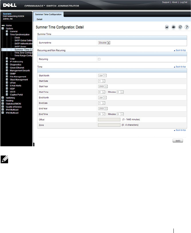
Managing General System Settings 299
Summer Time Configuration
Use the Summer Time Configuration page to configure summer time
(daylight saving time) settings.
To display the Summer Time Configuration page, click System
→
Time
Synchronization
→
Summer Time Configuration in the navigation panel.
Figure 12-15. Summer Time Configuration
To use the preconfigured summer time settings for the United States or
European Union, select the Recurring check box and specify USA or EU from
the Location menu.
NOTE: The fields on the Summer Time Configuration page change when you
select or clear the Recurring check box.
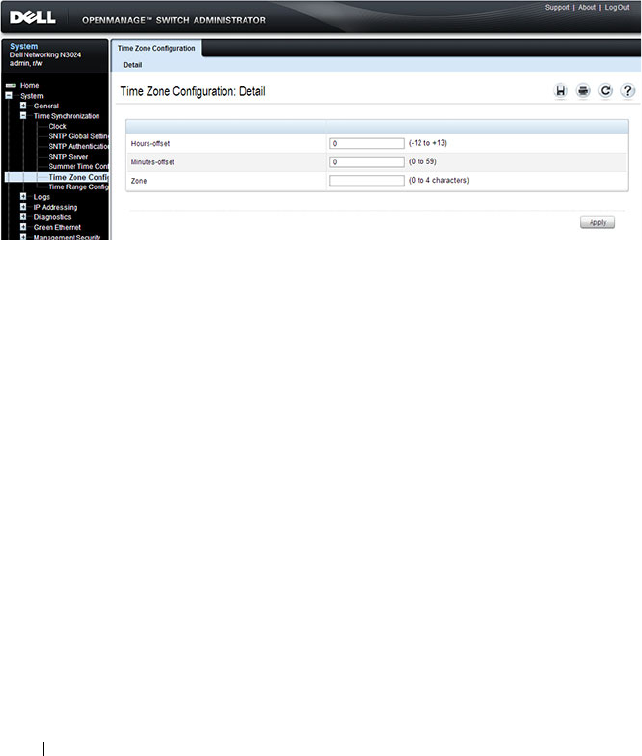
300 Managing General System Settings
Time Zone Configuration
Use the Time Zone Configuration to configure time zone information,
including the amount time the local time is offset from UTC and the
acronym that represents the local time zone.
To display the Time Zone Configuration page, click System
→
Time
Synchronization
→
Time Zone Configuration in the navigation panel.
Figure 12-16. Time Zone Configuration
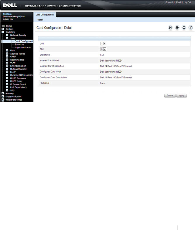
Managing General System Settings 301
Card Configuration
Use the Card Configuration page
to control the administrative status of the
rear-panel expansion slots (Slot 1 or Slot 2) and to configure the plug-in
module to use in the slot.
To display the Card Configuration
page, click Switching
→
Slots
→
Card
Configuration in the navigation panel.
Figure 12-17. Card Configuration
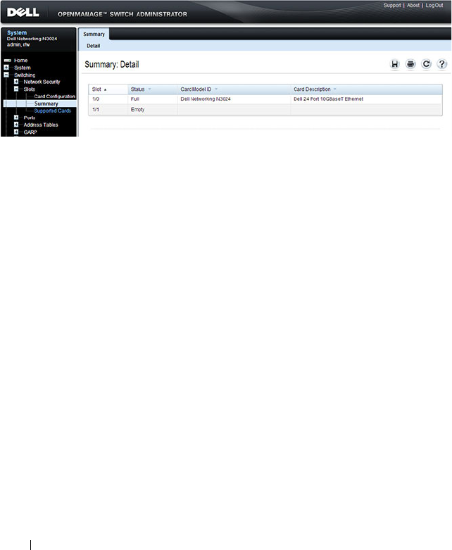
302 Managing General System Settings
Slot Summary
Use the Slot Summary page
to view information about the expansion slot
status.
To display the Slot Summary page, click Switching
→
Slots
→
Summary in
the navigation panel.
Figure 12-18. Slot Summary
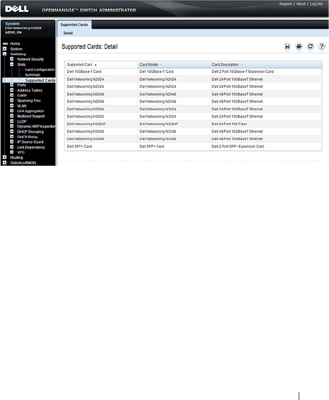
Managing General System Settings 303
Supported Cards
Use the Supported Cards page
to view information about the supported
plug-in modules for the switch.
To display the Supported Cards page, click Switching
→
Slots
→
Supported
Cards in the navigation panel.
Figure 12-19. Supported Cards
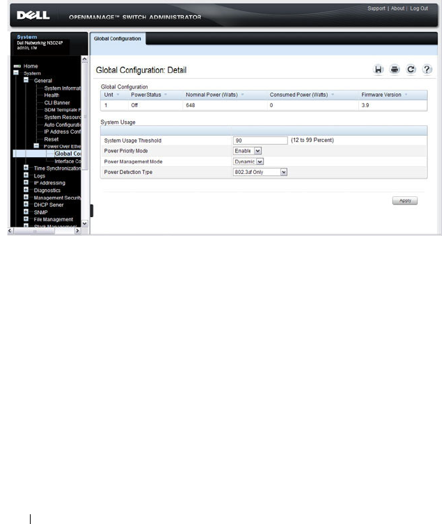
304 Managing General System Settings
Power Over Ethernet Global Configuration (N2024P/N2048P and
N3024P/N3048P Only)
Use the PoE Global Configuration page
to configure the PoE settings for the
switch.
To display the PoE Global Configuration
page, click System
→
General
→
Power over Ethernet
→
Global Configuration in the navigation panel.
Figure 12-20. PoE Global Configuration
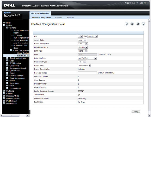
Managing General System Settings 305
Power Over Ethernet Interface Configuration (N2024P/N2048P and
N3024P/N3048P Only)
Use the PoE Interface Configuration page
to configure the per-port PoE
settings. From this page, you can also access the PoE Counters table and PoE
Port Table. The PoE Port table allows you to view and configure PoE settings
for multiple ports on the same page.
To display the PoE Interface Configuration
page, click System
→
General
→
Power over Ethernet
→
Interface Configuration in the navigation panel.
Figure 12-21. PoE Interface Configuration
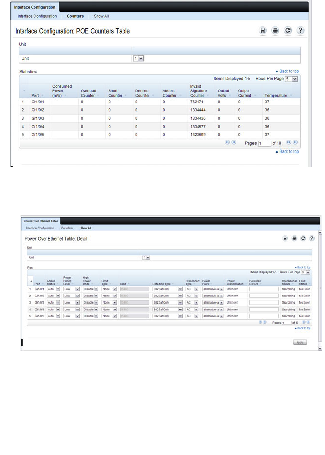
306 Managing General System Settings
To view PoE statistics for each port, click Counters.
Figure 12-22. PoE Counters Table
To view the PoE Port Table, click Show All.
Figure 12-23. PoE Port Table
If you change any settings for one or more ports on the PoE Port Table page,
click Apply to update the switch with the new settings.

Managing General System Settings 307
Configuring System Settings (CLI)
This section provides information about the commands you use to configure
system information and time settings on the Dell Networking N2000, N3000,
and N4000 series switches. For more information about these commands, see
the
Dell Networking N2000, N3000, and N4000 Series Switches CLI
Reference Guide
at support.dell.com/manuals.
Configuring System Information
Beginning in Privileged EXEC mode, use the following commands to
configure system information.
Command Purpose
configure Enter Global Configuration mode.
hostname
name
Configure the system name. The CLI prompt changes to
the host name after you execute the command.
snmp-server contact
name
Configure the name of the switch administrator. If the
name contains a space, use quotation marks around the
name.
snmp-server location
location
Configure the switch location.
asset-tag [unit
unit_id
]
tag
Configure the asset tag for the switch. Use the unit
keyword to configure the asset tag for each unit in a stack
of switches.
CTRL + Z Exit to Privileged EXEC mode.
show system [id] Display system information. Include the id keyword to
display additional system information.

308 Managing General System Settings
Configuring the Banner
Beginning in Privileged EXEC mode, use the following commands to
configure the MOTD, login, or User EXEC banner. The switch supports the
following banner messages:
• MOTD—Displays when a user connects to the switch.
• Login—Displays after the MOTD banner and before the login prompt.
• Exec—Displays immediately after the user logs on to the switch.
Command Purpose
configure Enter Global Configuration mode.
banner
{motd|login|exec}
text
Configure the banner message that displays when you
connect to the switch (motd and login) or enter User
EXEC mode (exec).
Use quotation marks around a message if it includes
spaces.
line
{telnet|ssh|console}
Enter the terminal line configuration mode for Telnet,
SSH, or the console.
motd-banner Specify that the configured MOTD banner displays. To
prevent the banner from displaying, enter no motd-
banner.
exec-banner Specify that the configured exec banner displays. To
prevent the banner from displaying, enter no exec-banner.
login-banner Specify that the configured login banner displays. To
prevent the banner from displaying, enter no login-banner.
CTRL + Z Exit to Privileged EXEC mode.
show banner Display the banner status on all line terminals.

Managing General System Settings 309
Managing the SDM Template
Beginning in Privileged EXEC mode, use the following commands to set the
SDM template preference and to view information about the available SDM
templates.
Configuring SNTP Authentication and an SNTP Server
Beginning in Privileged EXEC mode, use the following commands to require
the SNTP client to use authentication when communicating with the SNTP
server. The commands also show how to configure an SNTP server.
Requiring authentication is optional. However, if you configure
authentication on the switch SNTP client, the SNTP server must be
configured with the same authentication information to allow time
synchronization to take place between the two devices.
Command Purpose
configure Enter Global Configuration mode.
sdm prefer {dual-ipv4-
and-ipv6 default| ipv4-
routing {data-center |
default}}
Select the SDM template to apply to the switch after the
next boot.
CTRL + Z Exit to Privileged EXEC mode.
show sdm prefer
[
template
]
View information about the SDM template the switch is
currently using. Use the
template
variable to view the
parameters for the specified template.
Command Purpose
configure Enter Global Configuration mode.
sntp authentication-key
key_id
md5
key_word
Define an authentication key for SNTP. The variables are:
•
key_id
— The encryption key ID, which is a number from
1–4294967295.
•
key_word
—The authentication key, which is a string of
up to eight characters.

310 Managing General System Settings
sntp trusted-key
key_id
Specify the authentication key the SNTP server must
include in SNTP packets that it sends to the switch.
The
key_id
number must be an encryption key ID defined
in the previous step.
sntp authenticate Require authentication for communication with the SNTP
server.
A trusted key must be configured before this command is
executed.
sntp server {
ip_address
|
hostname
} [priority
priority
] [key
key_id
]
Define the SNTP server.
•
ip_address
—The IP address (or host name) of the SNTP
server to poll. The IP address can be an IPv4 or IPv6
address.
•
priority
—(Optional) If multiple SNTP servers are
defined, this number determines which server the switch
polls first. The priority is 1–8, where 1 is the highest
priority. If you do not specify a priority, the servers are
polled in the order that they are entered.
•
key_id
—(Optional) Enter an authentication key to use.
The key must be previously defined by the
sntp
authentication-key
command.
sntp
{unicast|broadcast}
client enable
This command enables the SNTP client and allows the
switch to poll configured unicast SNTP servers for updates
or receive broadcasts from any SNTP server.
sntp client poll timer
seconds
Specify how often the SNTP client requests SNTP packets
from the configured server(s).
seconds
—The poll interval can be 64, 128, 256, 512, or
1024 seconds.
CTRL + Z Exit to Privileged EXEC mode.
show sntp configuration Verify the SNTP configuration.
show sntp status View information about the SNTP updates.
Command Purpose

Managing General System Settings 311
Setting the System Time and Date Manually
Beginning in Privileged EXEC mode, use the following commands to
configure the time and date, time zone, and summer time settings.
Command Purpose
clock set {
mm/dd/yyyy
hh:mm:ss
} |
{
hh:mm:ss
mm/dd/yyyy
Configure the time and date. You can enter the time first
and then the date, or the date and then the time.
•
hh:mm:ss
—Time in hours (24-hour format, from 01-24),
minutes (00-59), and seconds (00-59).
•
mm/dd/yyyy
— Two digit month (1-12), two-digit date of
the month (01-31), and four-digit year.
clock timezone hours-
offset
hours-offset
[minutes
minutes-
offset
] [zone
acronym
]
Configure the time zone settings.
•
hours-offset
— Hours difference from UTC. (Range: –12 to
+13)
•
minutes-offset
— Minutes difference from UTC. (Range:
0–59)
•
acronym
— The acronym for the time zone. (Range: Up to
four characters)
clock summer-time
recurring {usa | eu |
{
week day month
hh:mm week day
month hh:mm
}}
[offset
offset
] [zone
acronym
]
Use this command if the summer time starts and ends every
year based on a set pattern.
For switches located in the United States or European
Union, use the usa or eu keywords to use the preconfigured
values. Otherwise, configure the start and end times by using
the following values:
•
week
— Week of the month. (Range: 1–5, first, last)
•
day
— Day of the week. (The first three letters by name)
•
month
— Month. (The first three letters by name; jan, for
example.)
•
hh:mm
— Time in 24-hour format in hours and minutes.
(Range: hh: 0–23, mm: 0–59)
•
offset
— Number of minutes to add during the
summertime. (Range:1–1440)
•
acronym
— The acronym for the time zone to be displayed
when summertime is in effect. (Up to four characters)

312 Managing General System Settings
Configuring the Expansion Slots (N3000 Series Only)
Beginning in Privileged EXEC mode, use the following commands to
configure and view information about the expansion slots and plug-in
modules (cards).
clock summer-time
date {
date month
|
month date
}
year
hh:mm
{
date month
|
month dat
e}
year
hh:mm
[offset
offset
]
[zone
acronym
]
Use this command if the summer time does not start and
end every year according to a recurring pattern. You can
enter the month and then the date, or the date and then the
month.
•
date
— Day of the month. (Range: 1-31.)
•
month
— Month. (Range: The first three letters by name)
•
hh:mm
— Time in 24-hour format in hours and minutes.
(Range: hh: 0–23, mm: 0–59)
•
offset
— Number of minutes to add during the
summertime. (Range:1–1440)
•
acronym
— The acronym for the time zone to be displayed
when summertime is in effect. (Range: Up to four
characters)
CTRL + Z Exit to Privileged EXEC mode.
show clock [detail] View information about the time. Include the detail
keyword to view information about the time zone and
summer time.
Command Purpose
configure Enter Global Configuration mode.
slot
unit/slot cardindex
Configured the specified slot (1–2) to use the plug-in
module identified by the
cardindex
number (CID). To
view the CID associated with each plug-in module, use the
show supported cardtype command.
CTRL + Z Exit to Privileged EXEC mode.
show slot Display status information about the expansion slots.
show supported cardtype Display information about the plug-in modules the switch
supports.
Command Purpose

Managing General System Settings 313
Viewing Slot Information (N4000 Series Only)
Use the following commands to view information about Slot 0 and its
support.
Configuring PoE Settings (N2024P/N2048P and N3024P/N3048P Only)
Beginning in Privileged EXEC mode, use the following commands to
configure PoE information.
Command Purpose
show slot Display status information about the expansion slots.
show supported cardtype Display information about the modules the switch
supports.
Command Purpose
configure Enter Global Configuration mode.
power inline usage-
threshold
threshold
Specify the maximum usage for PoE power on the system.
The
threshold
variable (range: 1–99%) is a percentage of
total system power.
power inline
management {class |
static | dynamic}
Set the power-management mode for the switch.
power inline detection
{dot3af |
dot3af+legacy}
Set the power-management mode for the switch.
•
802.3af-only
—IEEE 802.3af detection scheme is used.
•
802.3af+legacy
—IEEE 802.3af 4point detection scheme
is used and when it fails to detect a connected PD, legacy
capacitive detection is used.
interface
interface
Enter interface configuration mode for the specified port.
The
interface
variable includes the interface type and
number, for example gigabitethernet 1/0/3.
power inline {auto |
never}
Set the PoE device discovery admin mode.
•
auto
— Enables the device discovery protocol and, if
found, supplies power to the device.
•
never
— Disables the device discovery protocol and stops
supplying power to the device.

314 Managing General System Settings
power inline priority
{critical | high | low}
Configures the port priority level for the delivery of power
to an attached device.
power inline high-power Configure the port high power mode for connected-device
compatibility.
power inline limit
user-defined
limit
Set the per-port power limit.
•
user-defined
limit
—Allows the port to draw up to user
defined configured value. The range of
limit
is
3000–32000 milliwatts.
power inline powered-
device
type
Provide a description to represent the type of device
connected to the port.
power inline reset (Optional) Reset the port. You might use this command if
the port is stuck in an Error state.
CTRL + Z Exit to Privileged EXEC mode.
show power inline Display PoE information for the switch.
show power inline
interface
Display PoE information for the specified interface.
Command Purpose

Managing General System Settings 315
General System Settings Configuration Examples
This section contains the following examples:
• Configuring System and Banner Information
• Configuring SNTP
• Configuring the Time Manually
Configuring System and Banner Information
In this example, an administrator configures the following system
information:
• System name: N2048
• System contact: Jane Doe
• System location: RTP100
• Asset tag: 006429
The administrator then configures the MOTD banner to alert other switch
administrators of the connected topology.
To configure the switch:
1
Configure the hosts name.
console#configure
console(config)#hostname N2048
2
Configure the contact, location, and asset tag. Notice that the prompt
changed to the host name.
N2048(config)#snmp-server contact “Jane Doe”
N2048(config)#snmp-server location RTP100
N2048(config)#asset-tag 006429
3
Configure the message that displays when a user connects to the switch.
N2048(config)#banner motd “This switch connects
users in cubicles C121-C139.”
N2048(config)#exit
4
View system information to verify the configuration.
N2048#show system
System Description: Dell Ethernet Switch
System Up Time: 0 days, 19h:36m:36s

316 Managing General System Settings
System Contact: Jane Doe
System Name: N2048
System Location: RTP100
Burned In MAC Address: 001E.C9AA.AA07
System Object ID: 1.3.6.1.4.1.674.10895.3035
System Model ID: N2048
Machine Type: Dell Networking N2048
Temperature Sensors:
Unit Temperature (Celsius) Status
---- --------------------- ------
1 43 OK
Power Supplies:
Unit Description Status Source
---- ----------- ----------- ------
1 Main OK AC
1 Secondary Error DC
Temperature Sensors:
Unit Description Temperature Status
(Celsius)
---- ----------- ----------- ------
1 CPU 33 Good
1 MAC 39 Good
1 Left PHY 32 Good
1 Right PHY 33 Good
Fans:
Unit Description Status
---- ----------- ------
1 Fan 1 OK
1 Fan 2 OK
1 Fan 3 OK

Managing General System Settings 317
Power Supplies:
Unit Description Status Average Current Since
Power Power Date/Time
(Watts) (Watts)
---- ---------- -------- ---------- -------- ------------
1 System OK 5.0 97.8
1 Main Failure
1 Secondary OK 97.6 97.8 01/10/2031
15:59:05
5
View additional information about the system.
N2048#show system id
Service Tag:
Chassis Service Tag: N/A
Serial Number: 7048NX1011
Asset Tag: unit-1
Unit Service tag Chassis Serv tag Serial number Asset tag
---- ----------- ---------------- ------------- ---------
1 N/A 70498NX1011 unit-1
Service Tag: 0000000
Chassis Service Tag:
Serial Number: TW282987BK0002
Asset Tag: 111222
Unit Service tag Chassis Serv tag Serial number Asset tag
---- ------------ ---------------- ------------- ----------
1 0000000 TW282987BK0002 111222
6
Initiate a new Telnet session to verify the MOTD.
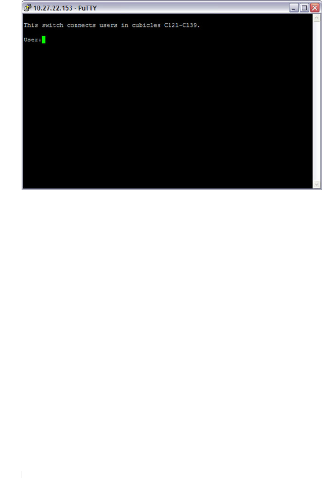
318 Managing General System Settings
Figure 12-24. Verify MOTD

Managing General System Settings 319
Configuring SNTP
The commands in this example configure the switch to poll an SNTP server
to synchronize the time. Additionally, the SNTP sessions between the client
and server must be authenticated.
To configure the switch:
1
Configure the authentication information. The SNTP server must be
configured with the same authentication key and ID.
console#configure
console(config)#sntp authentication-key 23456465
md5 sntpkey
console(config)#sntp trusted-key 23456465
console(config)#sntp authenticate
2
Specify the IP address of the SNTP server to poll and include the
authentication key. This command automatically enables polling and sets
the priority to 1.
console(config)#sntp server 192.168.10.30 key
23456465
console(config)#sntp unicast client enable
3
Verify the configuration.
console#show sntp configuration
Polling interval: 512 seconds
MD5 Authentication keys: 23456465
Authentication is required for synchronization.
Trusted keys: 23456465
Unicast clients: Enable
Unicast servers:
Server Key Polling Priority
------------ ----------- --------- --------
192.168.10.30 23456465 Enabled 1

320 Managing General System Settings
4
View the SNTP status on the switch.
console#show sntp status
Client Mode: Unicast
Last Update Time: MAR 01 09:12:43 2010
Unicast servers:
Server Status Last response
--------------- ------------ ---------------------
192.168.10.30 Other 09:12:43 Mar 1 2011

Managing General System Settings 321
Configuring the Time Manually
The commands in this example manually set the system time and date. The
time zone is set to Eastern Standard Time (EST), which has an offset of -5
hours. Summer time is enabled and uses the preconfigured United States
settings.
To configure the switch:
1
Configure the time zone offset and acronym.
console#configure
console(config)#clock timezone -5 zone EST
2
Configure the summer time (daylight saving time) to use the
preconfigured settings for the United States.
console(config)#clock summer-time recurring us
3
Set the local time and date.
console(config)#clock set 16:13.06 03/01/2010
4
Verify the time settings.
console#show clock detail
00:27:19 EST(UTC-5:00) Feb 3 2039
No time source
Time zone:
Acronym is EST
Offset is UTC-5:00
Summertime:
Acronym not configured
Recurring every year (USA)
Begins on second Sunday of Mar at 02:00
Ends on first Sunday of Nov at 02:00
Offset is +60 minutes

322 Managing General System Settings

Configuring SNMP 323
13
Configuring SNMP
The topics covered in this chapter include:
• SNMP Overview
• Default SNMP Values
• Configuring SNMP (Web)
• Configuring SNMP (CLI)
• SNMP Configuration Examples
SNMP Overview
Simple Network Management Protocol
(SNMP) provides a method for
managing network devices. The Dell Networking series switches support
SNMP version 1, SNMP version 2, and SNMP version 3.
What Is SNMP?
SNMP is a standard protocol that enables remote monitoring and
management of a device through communication between an SNMP
manager and an SNMP agent on the remote device. The SNMP manager is
typically part of a Network Management System (NMS) that runs on an
administrative host. The switch software includes
Management Information
Base
(MIB) objects that the SNMP agent queries and modifies. The switch
uses standard public MIBs and private MIBs.
A MIB acts as a structured road map for managed objects. A managed object
is any feature or setting that can be configured or monitored on the switch.
An Object Identifier (OID) is the unique number assigned to an object
defined in a MIB. An OID is written as a sequence of subidentifiers in
decimal notation.

324 Configuring SNMP
The SNMP agent maintains a list of variables that are used to manage the
switch. The variables are defined in the MIB. The MIB presents the variables
controlled by the agent. The SNMP agent defines the MIB specification
format, as well as the format used to access the information over the network.
Access rights to the SNMP agent are controlled by access strings.
SNMP v3 also applies access control and a new traps mechanism to SNMPv1
and SNMPv2 PDUs. In addition, the
User Security Model (USM) is defined
for SNMPv3 and includes:
• Authentication — Provides data integrity and data origin authentication.
• Privacy — Protects against disclosure of message content. Cipher-Bock-
Chaining
(CBC) is used for encryption. Either authentication is enabled
on an SNMP message, or both authentication and privacy are enabled on
an SNMP message. However privacy cannot be enabled without
authentication.
• Timeliness — Protects against message delay or message redundancy. The
SNMP agent compares incoming message to the message time
information.
• Key Management — Defines key generation, key updates, and key use.
Authentication or Privacy Keys are modified in the SNMPv3 User Security
Model (USM).
What Are SNMP Traps?
SNMP is frequently used to monitor systems for fault conditions such as
temperature violations, link failures, and so on. Management applications can
monitor for these conditions by polling the appropriate OIDs with the get
command and analyzing the returned data. This method has its drawbacks. If
it is done frequently, significant amounts of network bandwidth can be
consumed. If it is done infrequently, the response to the fault condition may
not occur in a timely fashion. SNMP traps avoid these limitations of the
polling method.
An SNMP trap is an asynchronous event indicating that something
significant has occurred. This is analogous to a pager receiving an important
message, except that he SNMP trap frequently contains all the information
needed to diagnose a fault.

Configuring SNMP 325
You can configure various features on the switch to generate SNMP traps that
inform the NMS about events or problems that occur on the switch. Traps
generated by the switch can also be viewed locally by using the web-based
interface or CLI.
Why Is SNMP Needed?
Some network administrators prefer to use SNMP as the switch management
interface. Settings that you view and configure by using the web-based Dell
OpenManage Switch Administrator and the CLI are also available by using
SNMP.
If you do not use NMS software to manage or monitor other devices on your
network, it might not be necessary to configure SNMP on the switch.
Default SNMP Values
By default, SNMPv2 is automatically enabled on the device. SNMPv1 and
SNMPv3 are disabled. To enable SNMPv3, you must define a local engine ID
for the device. The local engineID is by default set to the switch MAC
address, however when the switch operates in a stacking mode, it is important
to manually configure the local engineID for the stack. This local engineID
must be defined so that it is unique within the network. It is important to do
this because the default engineID in a stack is the MAC address of the master
unit, which may change if the master unit fails and another unit takes over
the stack.
Table 13-1 summarizes the default values for SNMP.
Table 13-1. SNMP Defaults
Parameter Default Value
SNMPv1 Disabled
SNMPv2 Enabled
SNMPv3 Disabled
SNMP traps Enabled
SNMP trap receiver None configured
Switch traps Enabled

326 Configuring SNMP
Table 13-2 describes the two views that are defined by default.
By default, three groups are defined. Table 13-3 describes the groups. The
Read, Write, and Notify values define the preconfigured views that are
associated with the groups.
QoS traps Enabled
Multicast traps Disabled
Captive Portal traps Disabled
OSPF traps Disabled
Table 13-2. SNMP Default Views
View Name OID Subtree View Type
Default iso Included
snmpVacmMIB Excluded
usmUser Excluded
snmpCommunityTable Excluded
DefaultSuper iso Included
Table 13-3. SNMP Default Groups
Group Name Security Level Read Write Notify
DefaultRead No Auth No Priv Default – Default
DefaultWrite No Auth No Priv Default Default Default
DefaultSuper No Auth No Priv DefaultSuper DefaultSuper DefaultSuper
Table 13-1. SNMP Defaults
Parameter Default Value
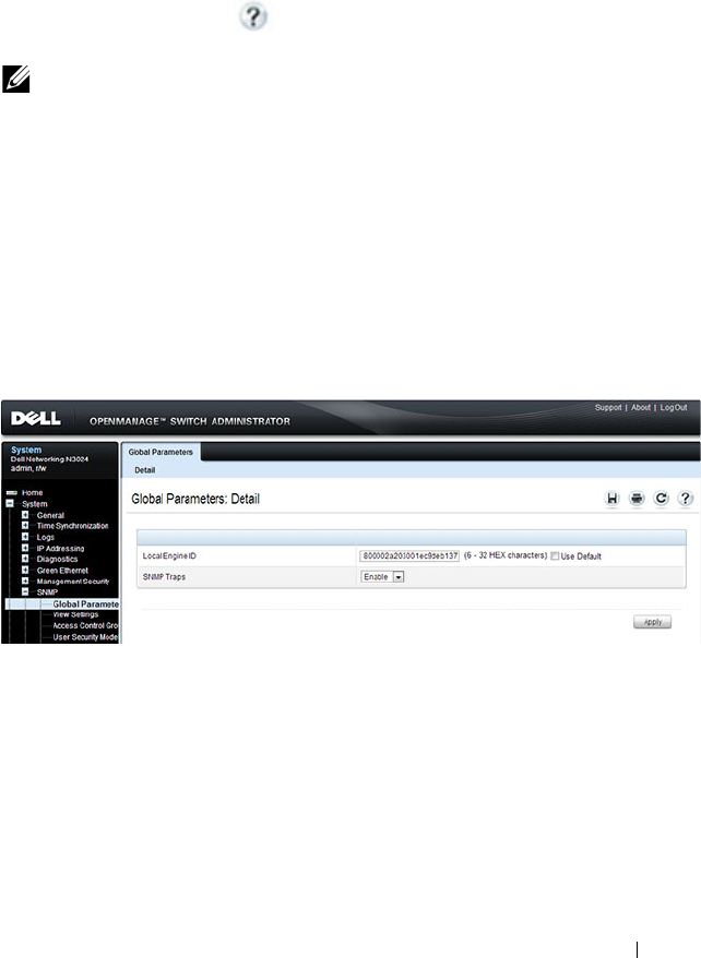
Configuring SNMP 327
Configuring SNMP (Web)
This section provides information about the OpenManage Switch
Administrator pages for configuring and monitoring the SNMP agent on a
Dell Networking N2000, N3000, and N4000 series switches. For details about
the fields on a page, click at the top of the page.
SNMP Global Parameters
Use the Global Parameters
page
to enable SNMP and Authentication
notifications.
To display the Global Parameters
page, click System
→
SNMP
→
Global
Parameters in the navigation panel.
Figure 13-1. SNMP Global Parameters
NOTE: For some features, the control to enable or disable traps is available from
a configuration page for that feature and not from the Trap Manager pages that
this chapter describes.
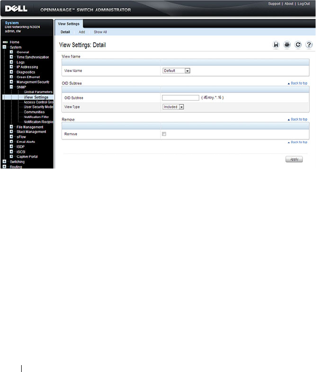
328 Configuring SNMP
SNMP View Settings
Use the SNMP View Settings page to create views that define which features
of the device are accessible and which are blocked. You can create a view that
includes or excludes OIDs corresponding to interfaces.
To display the View Settings page, click System
→
SNMP
→
View Settings in
the navigation panel.
Figure 13-2. SNMP View Settings
Adding an SNMP View
To add a view:
1
Open the
View Settings
page.
2
Click
Add
.
The
Add View
page displays:

Configuring SNMP 329
Figure 13-3. Add View
3
Specify a name for the view and a valid SNMP OID string.
4
Select the view type.
5
Click
Apply
.
The SNMP view is added, and the device is updated.
Click Show All to view information about configured SNMP Views.
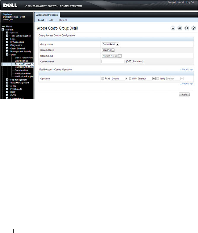
330 Configuring SNMP
Access Control Group
Use the Access Control Group page to view information for creating SNMP
groups, and to assign SNMP access privileges. Groups allow network
managers to assign access rights to specific device features or features aspects.
To display the Access Control Group page, click System
→
SNMP
→
Access
Control in the
navigation panel.
Figure 13-4. SNMP Access Control Group
Adding an SNMP Group
To add a group:
1
Open the
Access Control
Configuration
page.
2
Click
Add
.
The
Add an Access Control Configuration
page displays
:
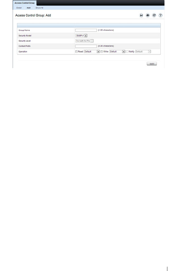
Configuring SNMP 331
Figure 13-5. Add Access Control Group
3
Specify a name for the group.
4
Select a security model and level
5
Define the context prefix and the operation.
6
Click
Apply
to update the switch.
Click Show All to view information about existing access control
configurations.
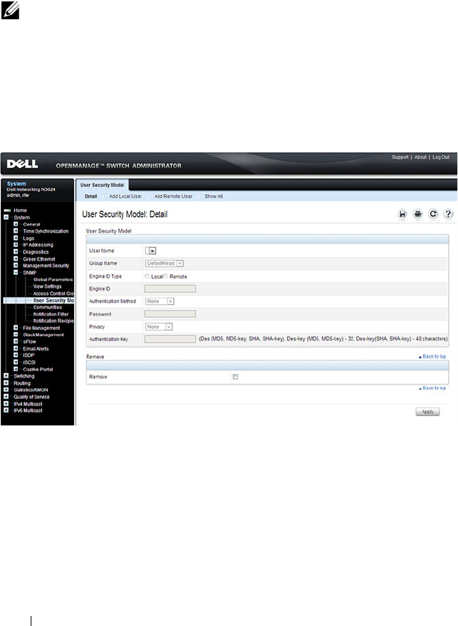
332 Configuring SNMP
SNMPv3 User Security Model (USM)
Use the User Security Model page to assign system users to SNMP groups
and to define the user authentication method.
To display the User Security Model page, click System
→
SNMP
→
User
Security Model in the
navigation panel.
Figure 13-6. SNMPv3 User Security Model
Adding Local SNMPv3 Users to a USM
To add local users:
1
Open the
User Security Model
page.
2
Click
Add
Local User
.
The
Add Local User
page displays:
NOTE: You can also use the Local User Database page under Management
Security to configure SNMPv3 settings for users. For more information, see
"Configuring Authentication, Authorization, and Accounting" on page 207.
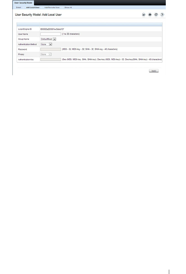
Configuring SNMP 333
Figure 13-7. Add Local Users
3
Define the relevant fields.
4
Click
Apply
to update the switch.
Click Show All to view the User Security Model Table, which contains
information about configured Local and Remote Users.
Adding Remote SNMPv3 Users to a USM
To add remote users:
1
Open the
SNMPv3 User Security Model
page.
2
Click
Add
Remote User
.
The
Add Remote User
page displays:
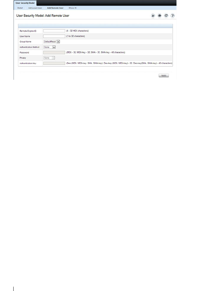
334 Configuring SNMP
Figure 13-8. Add Remote Users
3
Define the relevant fields.
4
Click
Apply
to update the switch.
Click Show All to view the User Security Model Table, which contains
information about configured Local and Remote Users.

Configuring SNMP 335
Communities
Access rights for SNMPv1 and SNMPv2 are managed by defining
communities Communities page. When the community names are changed,
access rights are also changed. SNMP Communities are defined only for
SNMP v1 and SNMP v2.
To display the Communities page, click System
→
SNMP
→
Communities
in the navigation panel.
Figure 13-9. SNMP Communities
Adding SNMP Communities
To add a community:
1
Open the
Communities
page.
2
Click
Add
.
The
Add SNMPv1,2 Community
page displays:
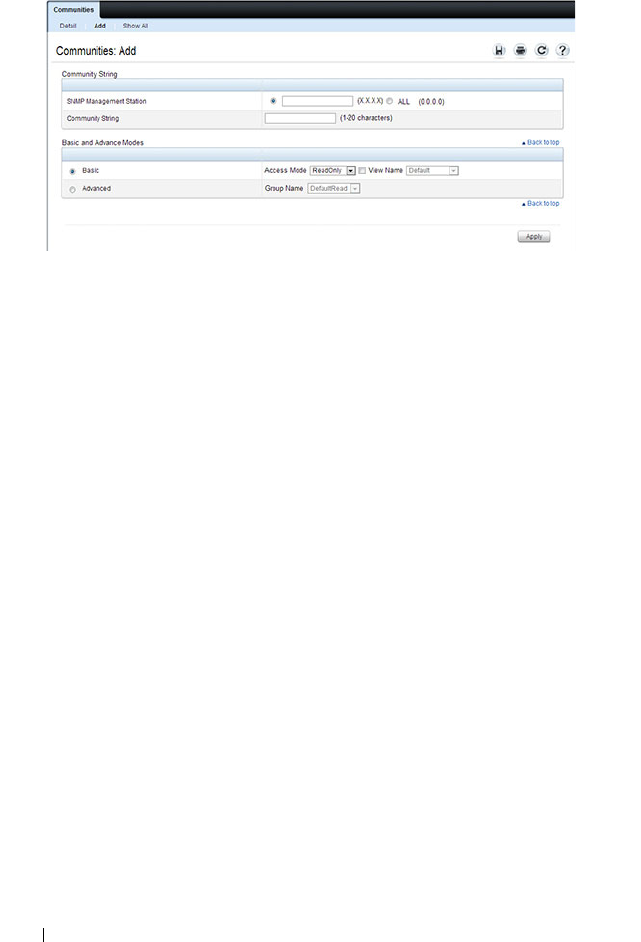
336 Configuring SNMP
Figure 13-10. Add SNMPv1,2 Community
3
Specify the IP address of an SNMP management station and the
community string to act as a password that will authenticate the
management station to the SNMP agent on the switch.
4
Select the access mode.
5
Click
Apply
to update the switch.
Click Show All to view the communities that have already been configured.
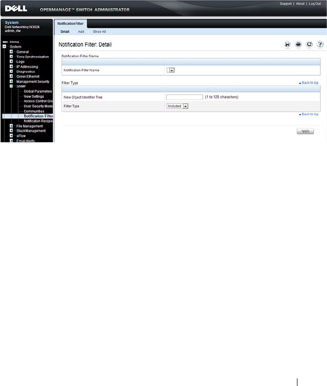
Configuring SNMP 337
Notification Filter
Use the Notification Filter page to set filtering traps based on OIDs. Each
OID is linked to a device feature or a feature aspect. The Notification Filter
page also allows you to filter notifications.
To display the Notification Filter page, click System
→
SNMP
→
Notification Filters in the
navigation panel
.
Figure 13-11. SNMP Notification Filter
Adding a Notification Filter
To add a filter:
1
Open the
Notification Filter
page.
2
Click
Add
.
The
Add Filter
page displays:

338 Configuring SNMP
Figure 13-12. Add Notification Filter
3
Specify the name of the filter, the OID for the filter.
4
Choose whether to send (include) traps or informs to the trap recipient or
prevent the switch from sending (exclude) the traps or informs.
5
Click
Apply
to update the switch.
Click Show All to view information about the filters that have already been
configured.
Notification Recipients
Use the Notification Recipients page
to view information for defining filters
that determine whether traps are sent to specific users, and the trap type sent.
SNMP notification filters provide the following services:
• Identifying Management Trap Targets
•Trap Filtering
• Selecting Trap Generation Parameters
• Providing Access Control Checks
To display the Notification Recipients page, click System
→
SNMP
→
Notification Recipient in the navigation panel.
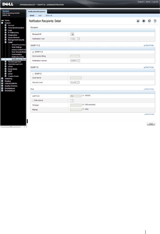
Configuring SNMP 339
Figure 13-13. SNMP Notification Recipient
Adding a Notification Recipient
To add a recipient:
1
Open the
Notification Recipient
page.
2
Click
Add
.
The
Add Recipient
page displays:
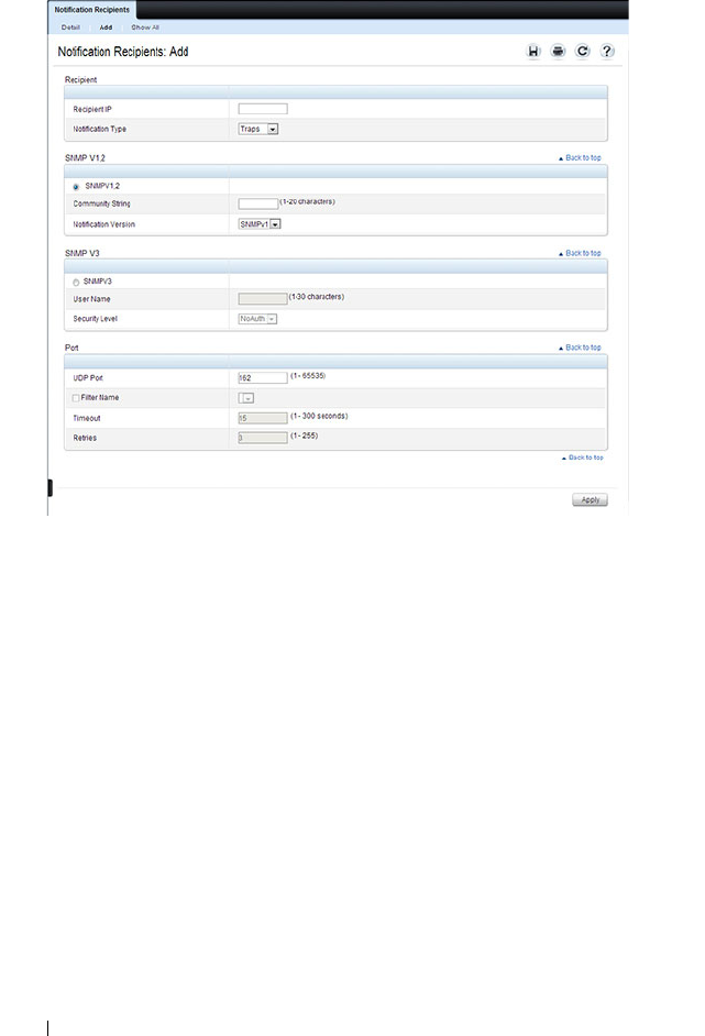
340 Configuring SNMP
Figure 13-14. Add Notification Recipient
3
Specify the IP address or hostname of the host to receive notifications.
4
Select whether to send traps or informs to the specified recipient
5
Define the relevant fields for the SNMP version you use.
6
Configure information about the port on the recipient.
7
Click
Apply
to update the switch.
Click Show All to view information about the recipients that have already
been configured.
Trap Flags
The Trap Flags page is used to specify which traps you want to enable or
disable. When the condition identified by an active trap is encountered by
the switch, a trap message is sent to any enabled SNMP Trap Receivers, and a
message is written to the trap log.
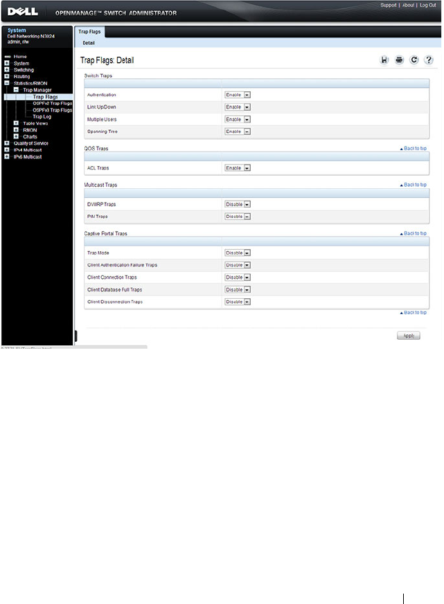
Configuring SNMP 341
To access the Trap Flags page, click Statistics/RMON
→
Trap Manager
→
Trap Flags in the navigation panel.
Figure 13-15. Trap Flags
OSPFv2 Trap Flags
The OSPFv2 Trap Flags page is used to specify which OSPFv2 traps you want
to enable or disable. When the condition identified by an active trap is
encountered by the switch, a trap message is sent to any enabled SNMP Trap
Receivers, and a message is written to the trap log.
To access the OSPFv2 Trap Flags page, click Statistics/RMON
→
Trap
Manager
→
OSPFv2 Trap Flags in the navigation panel.

342 Configuring SNMP
Figure 13-16. OSPFv2 Trap Flags
OSPFv3 Trap Flags
The OSPFv3 Trap Flags page is used to specify which OSPFv3 traps you want
to enable or disable. When the condition identified by an active trap is
encountered by the switch, a trap message is sent to any enabled SNMP Trap
Receivers, and a message is written to the trap log.
To access the OSPFv3 Trap Flags page, click Statistics/RMON
→
Trap
Manager
→
OSPFv3 Trap Flags in the navigation panel.
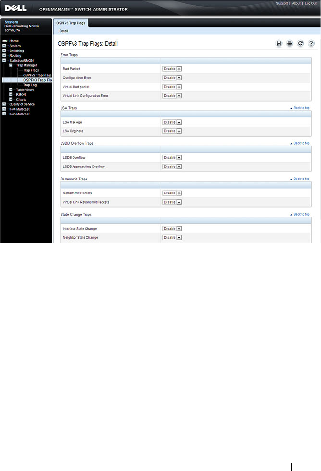
Configuring SNMP 343
Figure 13-17. OSPFv3 Trap Flags
Trap Log
The Trap Log page is used to view entries that have been written to the trap
log.
To access the Trap Log page, click Statistics/RMON
→
Trap Manager
→
Trap Log in the navigation panel.
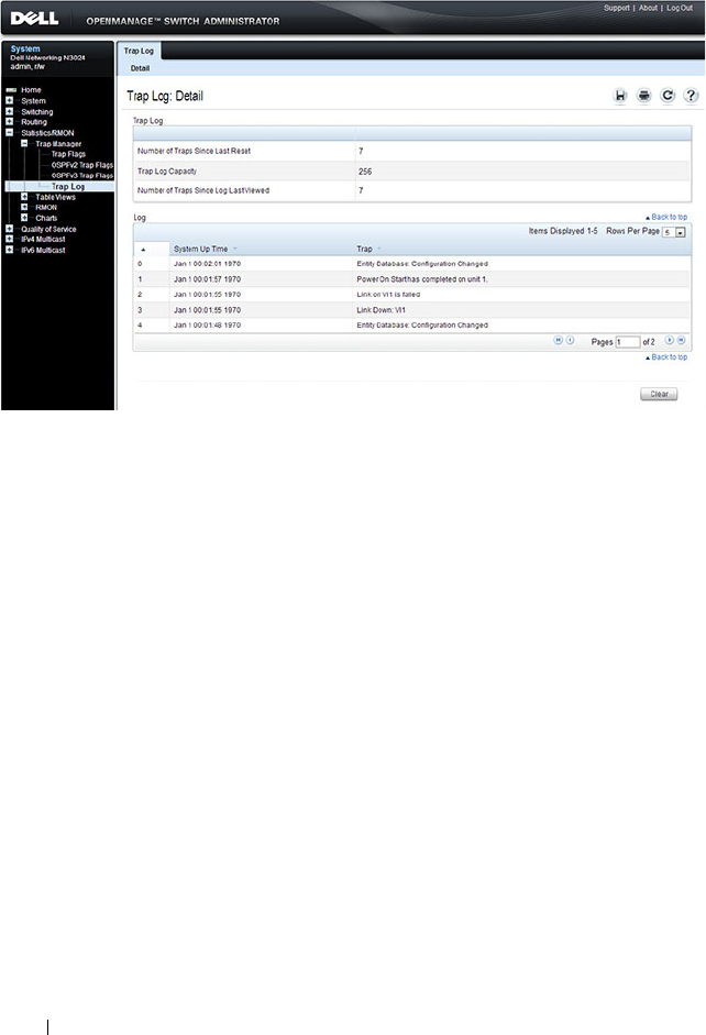
344 Configuring SNMP
Figure 13-18. Trap Logs
Click Clear to delete all entries from the trap log.

Configuring SNMP 345
Configuring SNMP (CLI)
This section provides information about the commands you use to manage
and view SNMP features on the switch. For more information about these
commands, see the
Dell Networking N2000, N3000, and N4000 Series
Switches CLI Reference Guide
at support.dell.com/manuals.
Configuring the SNMPv3 Engine ID
To use SNMPv3, the switch must have engine ID. You can specify your own
ID or use the default string that is generated using the MAC address of the
switch. If the SNMPv3 engine ID is deleted, or if the configuration file is
erased, then SNMPv3 cannot be used. Since the EngineID should be unique
within an administrative domain, Dell recommends that you
use the default
keyword to configure the Engine ID.
the following guidelines are recommended:
• For standalone switches use the default keyword to configure the Engine
ID.
• For a stack of switches, configure your own EngineID, and verify that is
unique within your administrative domain.
Changing the value of SNMP EngineID has important side-effects. A user's
password (entered on the command line) is converted to an MD5 or SHA
security digest. This digest is based on both the password and the local engine
ID. The command line password is then destroyed, as required by RFC 2274.
Because of this deletion, if the local value of engineID changes, the security
digests of SNMPv3 users will be invalid, and the users will have to be
reconfigured.
Beginning in Privileged EXEC mode, use the following commands to
configure an engine ID for SNMP.
Command Purpose
configure Enter Global Configuration mode

346 Configuring SNMP
Configuring SNMP Views, Groups, and Users
Beginning in Privileged EXEC mode, use the following commands to define
SNMP views, and SNMP groups, and local and remote SNMPv3 users.
snmp-server engineID
local {
engineid-string
|
default}
Configure the SNMPv3 Engine ID.
• engineid-string — The character string that identifies the
engine ID. The engine ID is a concatenated hexadecimal
string. Each byte in hexadecimal character strings is two
hexadecimal digits. Each byte can be separated by a
period or colon. (Range: 6-32 characters)
• default — The engineID is created automatically, based
on the device MAC address.
exit Exit to Privileged EXEC mode.
show snmp engineid View the local SNMP engine ID.
Command Purpose
configure Enter Global Configuration mode
snmp-server view
view-
name oid-tree
{included
| excluded}
Configure the SNMP view. When you configure groups,
users, and communities, you can specify a view to associate
with the group, user, or community
•
view-name
— Specifies the name of the view. (Range: 1-
30 characters.)
•
oid-tree
— Specifies the object identifier of the ASN.1
subtree to be included or excluded from the view. To
identify the subtree, specify a text string consisting of
numbers, such as
1.3.6.2.4
, or a word, such as
system
. Replace a single subidentifier with the asterisk
(*) wildcard to specify a subtree family; for example
1.3.*.4
.
•
included
— Indicates that the view type is included.
•
excluded
— Indicates that the view type is excluded.
Command Purpose

Configuring SNMP 347
snmp-server group
groupname
{v1 | v2 | v3
{noauth | auth | priv}
[notify
view-name
]}
[context
view-name
]
[read
view-name
] [write
view-name
]
Specify the identity string of the receiver and set the
receiver timeout value.
•
groupname
— Specifies the name of the group. (Range:
1-30 characters.)
•
v1
— Indicates the SNMP Version 1 security model.
•
v2
— Indicates the SNMP Version 2 security model.
•
v3
— Indicates the SNMP Version 3 security model.
•
noauth
— Indicates no authentication of a packet.
Applicable only to the SNMP Version 3 security model.
•
auth
— Indicates authentication of a packet without
encrypting it. Applicable only to the SNMP Version 3
security model.
•
priv
— Indicates authentication of a packet with
encryption. Applicable only to the SNMP Version 3
security model.
•
view-name
— Specifies the view (defined in the previous
step) to use for the context, notification, read, and write
privileges for the group.
Command Purpose

348 Configuring SNMP
snmp-server user
username groupname
[remote
engineid-string
]
[{auth-md5
password
|
auth-sha
password
|
auth-md5-key
md5-key
|
auth-sha-key
sha-key
}
[priv-des
password
|
priv-des-key
des-key
]]
Configure a new SNMPv3 user.
•
username
— Specifies the name of the user on the host
that connects to the agent. (Range: 1-30 characters.)
•
groupname
— Specifies the name of the group to which
the user belongs. (Range: 1-30 characters.)
•
engineid-string
— Specifies the engine ID of the remote
SNMP entity to which the user belongs. The engine ID is
a concatenated hexadecimal string. Each byte in the
hexadecimal character string is two hexadecimal digits.
The remote engine id designates the remote management
station, and should be defined to enable the device to
receive acknowledgements to "informs." (Range: 5-32
characters.)
•
auth-md5
— The HMAC-MD5-96 authentication level.
•
auth-sha
— The HMAC-SHA-96 authentication level.
•
password
— A password. (Range: 1 to 32 characters.)
•auth-
md5-key
— The HMAC-MD5-96 authentication
level. Enter a pregenerated MD5 key.
•auth-
sha-key
— The HMAC-SHA-96 authentication
level. Enter a pregenerated SHA key.
•
md5-key
— Character string
—
length 32 hex characters.
•
sha-key
— Character string
—
length 48 characters.
•
priv-des
— The CBC-DES Symmetric Encryption
privacy level. Enter a password.
•
priv-des-key
— The CBC-DES Symmetric Encryption
privacy level. The user should enter a pregenerated MD5
or SHA key depending on the authentication level
selected.
•
des-key
— The pregenerated DES encryption key. Length
is determined by authentication method selected
—
32
hex characters if MD5 Authentication is selected, 48 hex
characters if SHA Authentication is selected.
exit Exit to Privileged EXEC mode.
show snmp views View SNMP view configuration information.
Command Purpose

Configuring SNMP 349
Configuring Communities
Beginning in Privileged EXEC mode, use the following commands to
configure access rights for SNMPv1 and SNMPv2.
show snmp group
[
group_name
]
View SNMP group configuration information.
show snmp user
[
user_name
]
View SNMP user configuration information.
Command Purpose
configure Enter Global Configuration mode
snmp-server community
string
[ro | rw | su]
[view
view-name
]
[ipaddress
ip_address
]
Configure the community string and specify access criteria
for the community.
•
community-string —
Acts as a password and is used to
authenticate the SNMP management station to the
switch. The string must also be defined on the NMS in
order for the NMS to access the SNMP agent on the
switch (Range: 1-20 characters)
•
ro
—
Indicates read-only access
•
rw
—
Indicates read-write access.
•
view-name —
Specifies the name of a previously defined
MIB view.
•
ip_address
— Specifies the IP address of the management
station. If no IP address is specified, all management
stations are permitted
Command Purpose

350 Configuring SNMP
snmp-server community-
group
community
-
string
group-name
[ipaddress
ip-address
]
Map the internal security name for SNMP v1 and SNMP
v2 security models to the group name.
•
community-string —
Community string that acts like a
password and permits access to the SNMP protocol
.
(Range: 1-20 characters)
•
group-name —
Name of a previously defined group. The
group defines the objects available to the community.
(Range: 1-30 characters)
•
ip-address
— Management station IP address. Default is
all IP addresses.
exit Exit to Privileged EXEC mode.
show snmp View SNMP settings and verify the configuration
Command Purpose

Configuring SNMP 351
Configuring SNMP Notifications (Traps and Informs)
Beginning in Privileged EXEC mode, use the following commands to allow
the switch to send SNMP traps and to configure which traps are sent.
Command Purpose
configure Enter Global Configuration mode
snmp-server enable traps
[acl | all | auto-copy-sw
| captive-portal
cp-type
| dot1q | dvrmp | link |
maclock | multiple-
users | ospf
ospftype
|
ospfv3
ospfv3type
| pim
| poe | snmp
authentication |
spanning-tree | stack |
vrrp]
Specify the traps to enable. The captive portal, OSPF and
OSPFv3 traps include several different traps that can be
enabled. For more information, use the CLI command
help or see the CLI Command Reference.
snmp-server filter
filter-
name oid-tree
{included
| excluded}
Configure a filter for SNMP traps and informs based on
OIDs. Each OID is linked to a device feature or a feature
aspect.
•
filter-name
— Specifies the label for the filter record that
is being updated or created. The name is used to
reference the record. (Range: 1-30 characters.)
•
oid-tree
— Specifies the object identifier of the ASN.1
subtree to be included or excluded from the view. To
identify the subtree, specify a text string consisting of
numbers, such as
1.3.6.2.4
, or a word, such as
system
. Replace a single subidentifier with the asterisk
(*) wildcard to specify a subtree family; for example,
1.3.*.4
.
•
included
— Indicates that the filter type is included.
•
excluded
— Indicates that the filter type is excluded.

352 Configuring SNMP
snmp-server host
host-
addr
[informs [timeout
seconds
] [retries
retries
]
| traps version {1 | 2}]]
community-string
[udp-
port
port
] [filter
filtername
]
For SNMPv1 and SNMPv2, configure the system to receive
SNMP traps or informs.
•
host-addr
— Specifies the IP address of the host (targeted
recipient) or the name of the host. (Range:1-158
characters).
•
informs
— Indicates that SNMPv2 informs are sent to
this host
•
timeout
seconds
— Number of seconds to wait for an
acknowledgment before resending informs. The default is
15 seconds. (Range: 1-300 characters.)
•
retries
— Maximum number of times to resend an inform
request. The default is 3 attempts.
•
traps
— Indicates that SNMP traps are sent to this host
–
version 1
— Indicates that SNMPv1 traps will be used
–
version 2
— Indicates that SNMPv2 traps will be used
•
community-string
— Specifies a password-like
community string sent with the notification operation.
(Range: 1-20 characters)
•
port
— UDP port of the host to use. The default is 162.
(Range: 1-65535 characters.)
•
filtername
— A string that is the name of the filter that
defines the filter for this host. If unspecified, does not
filter anything (Range: 1-30 characters.)
Command Purpose

Configuring SNMP 353
snmp-server v3-host {
ip-
address
|
hostname
}
username
{traps |
informs} [noauth | auth
| priv] [timeout
seconds
] [retries
retries
]
[udpport
port
] [filter
filtername
]
For SNMPv3, configure the system to receive SNMP traps
or informs.
•
ip-address
— Specifies the IP address of the host
(targeted recipient).
•
hostname
— Specifies the name of the host. (Range: 1-
158 characters.)
•
username
— Specifies user name used to generate the
notification. (Range: 1-25 characters.)
•
traps
— Indicates that SNMP traps are sent to this host.
•
informs
— Indicates that SNMPv2 informs are sent to
this host.
•
noauth
— Specifies sending of a packet without
authentication.
•
auth
— Specifies authentication of a packet without
encrypting it
•
priv
— Specifies authentication and encryption of a
packet.
•
seconds
— Number of seconds to wait for an
acknowledgment before resending informs. This is not
allowed for hosts configured to send traps. The default is
15 seconds. (Range: 1-300 seconds.)
•
retries
— Maximum number of times to resend an inform
request. This is not allowed for hosts configured to send
traps. The default is 3 attempts. (Range: 0-255 retries.)
•
port
— UDP port of the host to use. The default is 162.
(Range: 1-65535.)
•
filter-name
— Specifies the optional filter (defined with
the
snmp-server filter
command) to use for the host.
(Range: 1-30 characters.)
exit Exit to Privileged EXEC mode.
show trapflags View the status of the configurable SNMP traps.
Command Purpose

354 Configuring SNMP
SNMP Configuration Examples
This section contains the following examples:
• Configuring SNMPv1 and SNMPv2
• Configuring SNMPv3
Configuring SNMPv1 and SNMPv2
This example shows how to complete a basic SNMPv1/v2 configuration. The
commands enable read-only access from any host to all objects on the switch
using the community string
public
, and enable read-write access from any
host to all objects on the switch using the community string
private
.
This example also shows how to allow the switch to generate traps for all
features that produce traps. The traps are sent to the host with an IP address
of 192.168.3.65 using the community string
public
.
To configure the switch:
1
Configure the public community string.
console#configure
console(config)#snmp-server community public ro
2
Configure the private community string.
console(config)#snmp-server community private rw
3
Enable all traps and specify the IP address of the host where the traps
should be sent.
console(config)#snmp-server enable traps all
console(config)#snmp-server host 192.168.3.65
public
console(config)#exit
4
View the current SNMP configuration on the switch.
console#show snmp
Community-String Community-Access View Name IP Address
-------------------- ---------------- --------- -------
private Read/Write Default All
public Read Only Default All

Configuring SNMP 355
Traps are enabled.
Authentication trap is enabled.
Version 1,2 notifications
Version 3 notifications
System Contact:
System Location:
Configuring SNMPv3
This example shows how to complete a basic SNMPv3 configuration. The
commands create a view that includes objects from the
internet
MIB subtree
(OID 1.3.6.1), which includes all objects on the switch.
The user named
admin
has read-write privileges to all objects within the view
(in other words, all objects on the switch) after supplying the appropriate
authentication credentials (secretkey).
To configure the switch:
1
Configure the view.
view_snmpv3
and specify the objects to include.
console#configure
console(config)#snmp-server view view_snmpv3
internet included
2
Create the group
group_snmpv3
and allow read-write access to the view
configured in the previous step.
console(config)#snmp-server group group_snmpv3 v3
auth read view_snmpv3 write view_snmpv3
Community-String Group Name IP Address
----------------- -------------- ------------
private DefaultWrite All
public DefaultRead All
Target Addr. Type Community Version UDP
Port
Filter
Name
TO
Sec
Retries
------------ ---- --------- ---- ----- ----- --- -------
192.168.3.65 Trap public 1 162
Target Addr. Type Username Security
Level
UDP
Port
Filter
Name
TO
Sec
Retries
------------ ---- --------- ------- ----- ----- --- -------

356 Configuring SNMP
3
Create the user
admin
, assign the user to the group, and specify the
authentication credentials.
console(config)#snmp-server user admin
group_snmpv3 auth-md5 secretkey
4
Specify the IP address of the host where traps are to be sent. Packet
authentication using MD5-SHA is enabled for the traps.
console(config)#snmp-server v3-host 192.168.3.35
admin traps auth
console(config)#exit
5
View the current SNMP configuration on the switch. The output includes
the SNMPv1/2 configuration in the previous example.
console#show snmp
Community-String Community-Access View Name IP Address
-------------------- ---------------- --------- -------
private Read/Write Default All
public Read Only Default All
Traps are enabled.
Authentication trap is enabled.
Version 1,2 notifications
Version 3 notifications
System Contact:
System Location:
Community-String Group Name IP Address
----------------- -------------- ------------
private DefaultWrite All
public DefaultRead All
Target Addr. Type Community Version UDP
Port
Filter
Name
TO
Sec
Retries
------------ ---- --------- ---- ----- ----- --- -------
192.168.3.65 Trap public 1 162
Target Addr. Type Username Security
Level
UDP
Port
Filter
Name
TO
Sec
Retries
------------ ---- --------- ------- ----- ----- --- -------
192.168.3.35 Trap admin Auth-NoP 162 15 3

Configuring SNMP 357
console#show snmp views
console#show snmp group
console#show snmp user
Name OID Tree Type
------------------ ------------------------ ------------
Default iso Included
Default snmpVacmMIB Excluded
Default usmUser Excluded
Default snmpCommunityTable Excluded
view_snmpv3 internet Included
DefaultSuper iso Included
Name Context
Prefix
Model Security
Level
Read Views
Write
Notify
------------ -------- ------ -------- -------- ------ -------
DefaultRead "" V1 NoAuth-
NoPriv
Default "" Default
DefaultRead "" V2 NoAuth-
NoPriv
Default "" Default
DefaultSuper "" V1 NoAuth-
NoPriv
DefaultSu
per
Default
Super
Default
Super
DefaultSuper "" V2 NoAuth-
NoPriv
DefaultSu
per
Default
Super
Default
Super
DefaultWrite "" V1 NoAuth-
NoPriv
Default Default Default
DefaultWrite "" V2 NoAuth-
NoPriv
Default Default Default
group_snmpv3 "" V3 Auth-
NoPriv
view_snmp
v3
view_sn
mpv3
""
Name Group Name Auth
Meth
Priv
Meth
Remote Engine ID
--------- ----------- ----- ----- ----------------
admin group_snmpv3 MD5 800002a203001ec9aaaa07

358 Configuring SNMP

Managing Images and Files 359
14
Managing Images and Files
This chapter describes how to upload, download, and copy files, such as
firmware images and configuration files, on the switch. The topics covered in
this chapter include:
• Image and File Management Overview
• Managing Images and Files (Web)
• Managing Images and Files (CLI)
• File and Image Management Configuration Examples
Image and File Management Overview
What Files Can Be Managed?
Dell Networking series switches maintain several different types of files on
the flash file system. Table 14-1 describes the files that you can manage. The
table also lists the type of action you can take on the file, which is one or more
of the following:
• Download the file to the switch from a remote system (or USB flash drive).
• Upload the file from the switch to a remote system (or USB flash drive).
• Copy the file from one location on the file system to another location.
NOTE: For information about the Auto Configuration feature that enables the
switch to automatically upgrade the image or load a new configuration file during
the boot process, see Automatically Updating the Image and Configuration.

360 Managing Images and Files
Table 14-1. Files to Manage
File Action Description
image Download
Upload
Copy
Firmware for the switch. The switch can
maintain two images: the active image and
the backup image.
startup-config Download
Upload
Copy
Contains the software configuration that
loads during the boot process.
running-config Download
Upload
Copy
Contains the current switch configuration.
backup-config Download
Upload
Copy
An additional configuration file that serves
as a backup.
Configuration script Download
Upload
Text file with CLI commands. When you
activate a script on the switch, the
commands are executed and added to the
running-config.
Log files Upload Provides various information about events
that occur on the switch. For more
information, see Monitoring and Logging
System Information.
SSH key files Download Contains information to authenticate SSH
sessions. The switch supports the following
files for SSH:
• SSH-1 RSA Key File
• SSH-2 RSA Key File (PEM Encoded)
• SSH-2 Digital Signature Algorithm (DSA)
Key File (PEM Encoded)

Managing Images and Files 361
Why Is File Management Needed?
This section provides some reasons why you might choose to manage various
files.
Image Files
The switch can store two firmware images, but only one is active. The other
image file is a backup image. By default, the switch has only one image. You
might copy an image or download an image to the switch for the following
reasons:
• To create a backup image
• To upgrade the firmware as new images become available
The Dell Networking series switches are named as follows:
<Switch name>v<version number>.stk
Where the switch name is:
N4000 — Dell Networking 4000 series switch firmware for:
SSL certificate files Download Contains information to encrypt,
authenticate, and validate HTTPS sessions.
The switch supports the following files for
SSL:
• SSL Trusted Root Certificate File (PEM
Encoded)
• SSL Server Certificate File (PEM
Encoded)
• SSL Diffie-Hellman Weak Encryption
Parameter File (PEM Encoded)
• SSL Diffie-Hellman Strong Encryption
Parameter File (PEM Encoded)
IAS Users Download List of Internal Authentication Server (IAS)
users for IEEE 802.1X authentication. For
more information, see What is the Internal
Authentication Server?
Table 14-1. Files to Manage
File Action Description
362 Managing Images and Files
• N4032, N4032F, N4064, N4064F
N3000
_
N2000
— Dell Networking 2000/3000 series switch firmware for:
• N2024, N2048, N2024P, N2048P, N3024, N3024P, N3024F, N3048,
N3048P
And the version number is:
Version Numbering Convention
• Major release numbers start at 6.
• Minor release numbers start at 0.
• Maintenance release numbers start at 0.
• Build numbers start at 1.
Examples:
•
N3000
_
N2000
v6.0.1.3.stk —
N3000
/
N2000
series switch firmware version
6.0.1.3. This is the third build for the first maintenance release for the 6.0
major release.
• N4000v6.1.0.1.stk — N4000 series switch firmware version 6.1.0.1. This is
the first build for the first minor release after the 6.0 major release, i.e.,
release 6.1.
Configuration Files
Configuration files contain the CLI commands that change the switch from
its default configuration. The switch can maintain three separate
configuration files: startup-config, running-config, and backup-config. The
switch loads the startup-config file when the switch boots. Any configuration
changes that take place after the boot process completes are written to the
Version number Description
6 0 0 1 Four part version number
Denotes the build number.
Denotes a scheduled maintenance release of the firmware.
Denotes a minor release of the firmware.
Denotes a major release of the firmware.

Managing Images and Files 363
running-config file. The backup-config file does not exist until you explicitly
create one by copying an existing configuration file to the backup-config file
or downloading a backup-config file to the switch.
You can also create configuration scripts, which are text files that contains
CLI commands.
When you apply (run) a configuration script on the switch, the commands in
the script are executed in the order in which they are written as if you were
typing them into the CLI. The commands that are executed in the
configuration script are added to the running-config file.
You might upload a configuration file from the switch to a remote server for
the following reasons:
• To create a backup copy
• To use the configuration file on another switch
• To manually edit the file
You might download a configuration file from a remote server to the switch
for the following reasons:
• To restore a previous configuration
• To load the configuration copied from another switch
• To load the same configuration file on multiple switches
Use a text editor to open a configuration file and view or change its contents.
SSH/SSL Files
If you use OpenManage Switch Administrator to manage the switch over an
HTTPS connection, you must copy the appropriate certificate files to the
switch. If you use the CLI to manage the switch over an SSH connection, you
must copy the appropriate key files to the switch.
What Methods Are Supported for File Management?
You can use any of the following protocols to download files from a remote
system to the switch or to upload files from the switch to a remote system:
NOTE: You must use the CLI to manage configuration scripts. The configuration
scripting feature is not available from the web interface.

364 Managing Images and Files
•TFTP
•SFTP
•SCP
•FTP
• HTTP (Web only)
• HTTPS (Web only)
You can also copy files between the file system on the internal flash and a
USB flash drive that is connected to the external USB port.
What Factors Should Be Considered When Managing Files?
Uploading and Downloading Files
To use TFTP, SFTP, SCP, or FTP for file management, you must provide the
IP address of the remote system that is running the appropriate server (TFTP,
SFTP, SCP or FTP). Make sure there is a route from the switch to the remote
system. You can use the ping command from the CLI to verify that a route
exists between the switch and the remote system.
If you are downloading a file from the remote system to the switch, be sure to
provide the correct path to the file and the correct file name.
Managing Images
When you download a new image to the switch, it overwrites the backup
image, if it exists. To use the new image, you must activate it and reload the
switch. The image that was previously the active image becomes the backup
image after the switch reloads. If you upgrade to a newer image and find that
it is not compatible with your network, you can revert to the original image.
If you activate a new image and reload the switch, and the switch is unable to
complete the boot process due to a corrupt image or other problem, you can
use the boot menu to activate the backup image. You must be connected to
the switch through the console port to access the boot menu. The image files
may contain firmware for the PHY processors on the switch. The PHY
firmware may be updated to the firmware version supported by the switch
firmware during the boot process or, in the case of switches that support the
hot swap of cards, when the card is inserted into the switch.

Managing Images and Files 365
Editing and Downloading Configuration Files
Each configuration file contains a list of executable CLI commands. The
commands must be complete and in a logical order, as if you were entering
them by using the switch CLI.
When you download a startup-config or backup-config file to the switch, the
new file replaces the previous version. To change the running-config file, you
execute CLI commands either by typing them into the CLI or by applying a
configuration script with the script apply command. The startup-config and
backup-config files can also be applied to the running-config by using the
script apply command.
Creating and Applying Configuration Scripts
When you use configuration scripting, keep the following considerations and
rules in mind:
• The application of scripts is partial if the script fails. For example, if the
script executes four of ten commands and the script fails, the script stops
at four, and the final six commands are not executed.
• Scripts cannot be modified or deleted while being applied.
• Validation of scripts checks for syntax errors only. It does not validate that
the script will run.
• The file extension must be .
scr
.
• A maximum of seven scripts are allowed on the switch.
• The combined size of all script files on the switch cannot exceed 2 MB.
• The maximum number of configuration file command lines is 2000.
You can type single-line annotations in the configuration file to improve
script readability. The exclamation point (!) character flags the beginning of a
comment. The comment flag character can begin anywhere within a single
line, and all input following this character to the end of the line is ignored.
Any line in the file that begins with the “!” character is recognized as a
comment line and ignored by the parser.
The following example shows annotations within a file (commands are bold):
! Script file for displaying management access
show telnet !Displays the information about remote
connections

366 Managing Images and Files
! Display information about direct connections
show serial
! End of the script file
Managing Files on a Stack
Image files downloaded to the master unit of a stack are automatically
downloaded to all stack members. If you activate the backup image on the
master, it is activated on all units as well so that when you reload the stack, all
units use the same image.
The running-config, startup-config, and backup-config files, as well as all keys
and certificates are synchronized across the stack when the running-config
file is saved to the startup-config file.
Configuration scripts are not distributed across the stack and only exist on
the unit that is the master unit at the time of the file download.
Uploading Configuration Files by Using SNMP
When you use SNMP to upload a configuration file to a TFTP server, the
agentTransferUploadFileName object must be set to the local filename,
which is either startup-config or backup-config.
How Is the Running Configuration Saved?
Changes you make to the switch configuration while the switch is operating
are written to the running-config. These changes are not automatically
written to the startup-config. When you reload the switch, the startup-config
file is loaded. If you reload the switch (or if the switch resets unexpectedly),
any settings in the running-config that were not explicitly saved to the
startup-config are lost. You must save the running-config to the startup-
config to ensure that the settings you configure on the switch are saved across
a switch reset.
To save the running-config to the startup-config by using the web-based
interface, click (the save icon), which is available at the top of each page.
To save the running-config to the startup-config from the CLI, use the write
command.
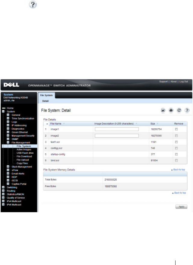
Managing Images and Files 367
Managing Images and Files (Web)
This section provides information about the OpenManage Switch
Administrator pages to use to manage images and files on a Dell Networking
N2000, N3000, and N4000 series switches. For details about the fields on a
page, click at the top of the page.
File System
Use the File System page to view a list of the files on the device and to modify
the image file descriptions.
To display the File System page, click System
→
File Management
→
File
System in the navigation panel.
Figure 14-1. File System

368 Managing Images and Files
Active Images
Use the Active Images
page to set the firmware image to use when the switch
boots. If you change the boot image, it does not become the active image
until you reset the switch.
On the N4000 series switches, the images are named
active
and
backup
.
NOTE:
To display the Active Images page, click System
→
File Management
→
Active Images in the navigation panel.
Figure 14-2. Active Images
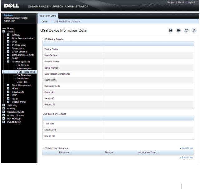
Managing Images and Files 369
USB Flash Drive
Use the USB Flash Drive page to view information about a USB flash drive
connected to the USB port on the front panel of the switch. The page also
displays information about the files stored on the USB flash drive.
A USB flash drive must be un-mounted by the operator before removing it
from the switch. If a new USB flash drive is installed without un-mounting
the previous drive, the new flash drive may not be recognized. If a USB flash
drive is removed without un-mounting it, un-mount the flash drive (i.e., use
the command unmount usb) and remove and reinstall the USB flash drive in
the switch.
To display the USB Flash Drive page, click System
→
File Management
→
USB Flash Drive in the navigation panel.
Figure 14-3. USB Flash Drive
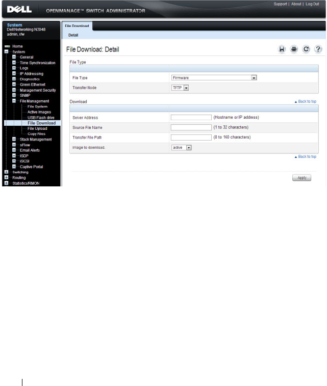
370 Managing Images and Files
File Download
Use the File Download page to download image (binary) files, SSH and SSL
certificates, IAS User files, and configuration (ASCII), files from a remote
server to the switch.
To display the File Download page, click System
→
File Management
→
File
Download in the navigation panel.
Figure 14-4. File Download
Downloading Files
To download a file to the switch:
1
Open the
File Download
page.
2
Select the type of file to download to the switch.
3
Select the transfer mode.
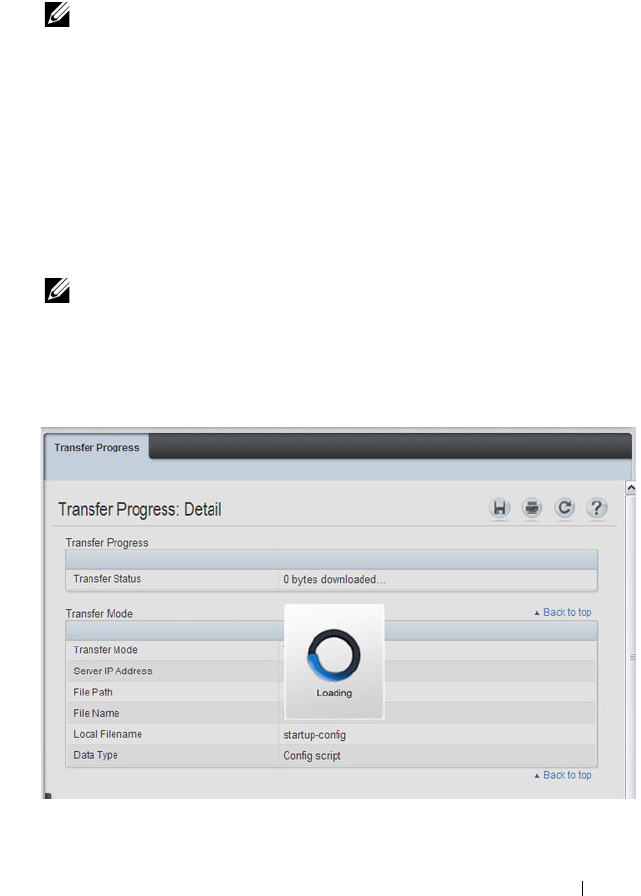
Managing Images and Files 371
If you select a transfer mode that requires authentication, additional fields
appear in the Download section. If you select HTTP as the download
method, some of the fields are hidden.
4
To download using HTTP, click
Browse
and select the file to download,
then click
Apply
.
5
To download using any method other than HTTP, enter the IP address of
the server that contains the file to download, the name of the file and the
path on the server where it is located. For SFTP and SCP, provide the user
name and password.
6
Click
Apply
to begin the download.
Figure 14-5. File Download in Progress
7
The file is downloaded to the switch.
NOTE: If you are using HTTPS to manage the switch, the download method
will be HTTPS.
NOTE: After you start a file download, the page refreshes and a transfer
status field appears to indicate the number of bytes transferred. The web
interface is blocked until the file download is complete.
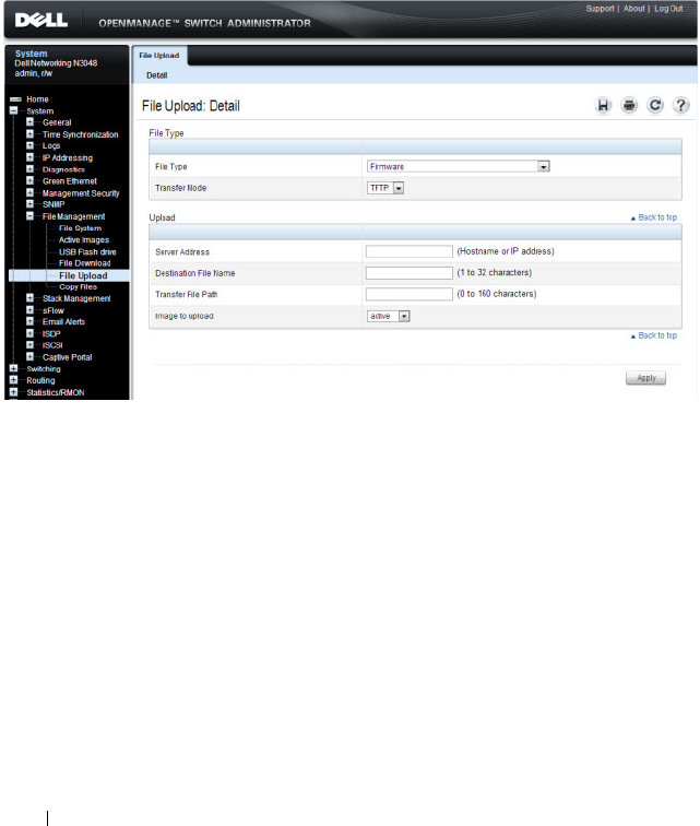
372 Managing Images and Files
File Upload
Use the File Upload to Server page to upload configuration (ASCII), image
(binary), IAS user, operational log, and startup log files from the switch to a
remote server.
To display the File Upload to Server page, click System
→
File Management
→
File Upload in the navigation panel.
Figure 14-6. File Upload
Uploading Files
To upload a file from the switch to a remote system:
1
Open the
File Upload
page.
2
Select the type of file to download to the remote server.
3
Select the transfer mode.
If you select a transfer mode that requires authentication, additional fields
appear in the Upload section. If you select HTTP as the upload method,
some of the fields are hidden.
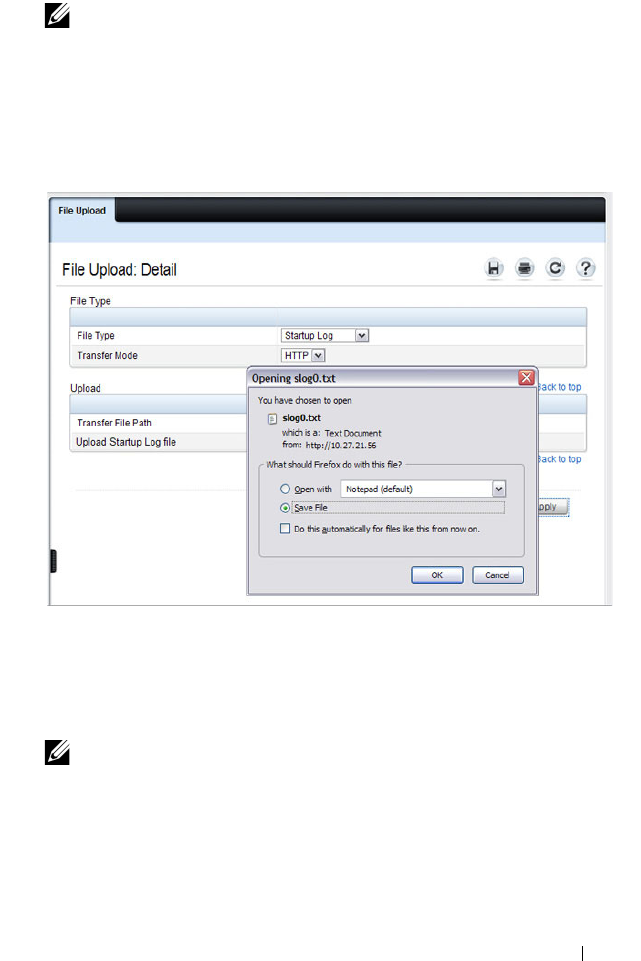
Managing Images and Files 373
4
To upload by using HTTP, click
Apply
. A dialog box opens to allow you to
open or save the file.
Figure 14-7. File Upload
5
To upload by using any method other than HTTP, enter the IP address of
the server and specify a name for the file. For SFTP and SCP, provide the
user name and password.
6
Click
Apply
to begin the upload.
7
The file is uploaded to the specified location on the remote server.
NOTE: If you are using HTTPS to manage the switch, the download method
will be HTTPS.
NOTE: For some file uploads and methods, the page refreshes and a
transfer status field appears to indicate the number of bytes transferred. The
web interface is blocked until the file upload is complete.
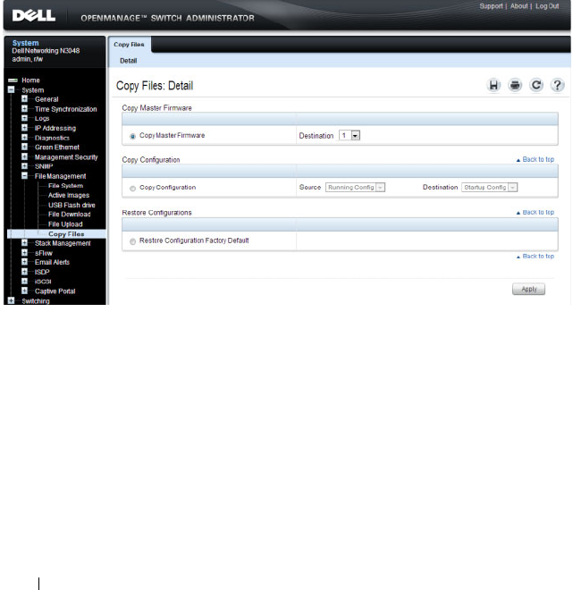
374 Managing Images and Files
Copy Files
Use the Copy Files page to:
• Copy the active firmware image to the switch. one or all members of a
stack.
• Copy the running, startup, or backup configuration file to the startup or
backup configuration file.
• Restore the running configuration to the factory default settings.
To display the Copy Files page, click System
→
File Management
→
Copy
Files in the navigation panel.
Figure 14-8. Copy Files

Managing Images and Files 375
Managing Images and Files (CLI)
This section provides information about the commands you use to upload,
download, and copy files to and from the Dell Networking N2000, N3000,
and N4000 series switches. For more information about these commands, see
the
Dell Networking N2000, N3000, and N4000 Series Switches CLI
Reference Guide
at support.dell.com/manuals. It also describes the
commands that control the Auto Configuration feature.
Downloading and Activating a New Image (TFTP)
Beginning in Privileged EXEC mode, use the following commands to
download a new firmware image to the switch and to make it the active
image. This example shows how to use TFTP to download the image.
NOTE: Upload, download, and copy functions use the copy command. The basic
syntax for the command is copy
source
destination
. This section shows several
different ways to use the copy command.
Command Purpose
copy tftp://{
ip-address
|
hostname
}/
path
/
file-
name
image
Use TFTP to download the firmware image at the
specified source to the non-active image.
If the image file is in the TFTP file system root (download
path), you do not need to specify the path in the
command.
On N4000 series switches, use the following command:
copy tftp://{
ip-address
|
hostname
}/
path
/
file-name
{active
| backup}
show version View information about the currently active image.
filedescr {image1 |
image2}
description
Add a description to the image files.
On N4000 series switches, use the following command:
filedescr {active | backup}
description

376 Managing Images and Files
boot system {image1 |
image2}
Set the image to use as the boot (active) image after the
switch resets. Images on the N4032/N4064 are named
active
and
backup
.
For N4000 series switches, use the following command:
boot system {active | backup}
reload Reboot the switch to make the new image the active
image.
You are prompted to verify that you want to continue.
Command Purpose

Managing Images and Files 377
Managing Files in Internal Flash
Beginning in Privileged EXEC mode, use the following commands to copy,
rename, delete and list the files in the internal flash.
Command Purpose
dir List the files in the flash file system.
copy flash://
filename
usb://
filename
Copy a file from the internal flash to a USB flash drive.
Use the dir command to see a list of the files that can be
copied from the internal flash.
Make sure a flash drive has been inserted in the USB port
on the front panel before executing the command.
rename
current_name
new_name
Rename a file in flash.
delete
filename
Remove the specified file.
erase {startup-config |
backup-image | backup-
config}
Erase the startup configuration, the backup configuration
or the backup image.
copy startup-config
backup-config
Save the startup configuration to the backup configuration
file.
copy running-config
startup-config
Copy the current configuration to the startup
configuration. This saves the current configuration to
NVRAM.
show startup-config View the contents of the startup-config file
show running-config View the contents of the running-config file
Command Purpose
dir List the files in the flash file system.
rename
current_name
new_name
Rename a file in flash.
delete
filename
Remove the specified file.
erase {startup-config |
backup-image | backup-
config}
Erase the startup configuration, the backup configuration
or the backup image.

378 Managing Images and Files
copy startup-config
backup-config
Save the startup configuration to the backup configuration
file.
copy running-config
startup-config
Copy the current configuration to the startup
configuration. This saves the current configuration to
NVRAM.
show startup-config View the contents of the startup-config file
show running-config View the contents of the running-config file
Command Purpose

Managing Images and Files 379
Managing Files on a USB Flash Device
Beginning in Privileged EXEC mode, use the following commands to manage
files that are on a USB device that is plugged into the USB flash port on the
front panel of the switch.
Uploading a Configuration File (SCP)
Beginning in Privileged EXEC mode, use the following commands to upload
a configuration file from the switch to a remote system by using SCP.
Command Purpose
show usb device Display USB flash device details
dir usb Display USB device contents and memory statistics
copy usb://
filename
{backup-config | image
| running-config | script
filename
| startup-config
|
filename
Copy the specified file from the USB flash device to the
specified file in internal flash.
unmount usb Make the USB flash device inactive.
Command Purpose
copy
file
scp://
user
@{
ip-
address
|
hostname
}/
path
/
file-name
Adds a description to an image file.
The file can be one of the following files:
•backup-config
•image
•operational-log
• running-config
•script
file-name
•startup-config
•startup-log
Password entry After you enter the copy command, the CLI prompts you
for the password associated with the username.

380 Managing Images and Files
Managing Configuration Scripts (SFTP)
Beginning in Privileged EXEC mode, use the following commands to
download a configuration script from a remote system to the switch, validate
the script, and activate it.
NOTE: The startup-config and backup-config files are essentially configuration
scripts and can be validated and applied by using the commands in this section.
Command Purpose
copy sftp://
user
@{
ip-
address
|
hostname
}/
path
/
file-name
script
dest-
name
Downloads the specified script from the remote server to
the switch.
Password entry After you enter the copy command, the CLI prompts you
for the password associated with the username.
script validate
script-
name
Checks the specified script for syntax errors.
The script is automatically validated when you download it
to the switch. You can validate again with this command.
script list View the list of available scripts.
script activate
script-
name
Executes the commands within the script in order. The
configuration changes in the script are applied to the
running configuration.
script show
script-name
View the contents of the specified script.

Managing Images and Files 381
File and Image Management Configuration
Examples
This section contains the following examples:
• Upgrading the Firmware
• Managing Configuration Scripts
Upgrading the Firmware
This example for a N4032 shows how to download a firmware image to the
switch and activate it. T
he TFTP server in this example is PumpKIN, an open
source TFTP server running on a Windows system.
• TFTP server IP address: 10.27.65.103
•File path: \image
• File name: dell_0308.stk
Use the following steps to prepare the download, and then download and
upgrade the switch image.
1
Check the connectivity between the switch and the TFTP server.
console#ping 10.27.65.103
Pinging 10.27.65.103 with 0 bytes of data:
Reply From 10.27.65.103: icmp_seq = 0. time <10 msec.
Reply From 10.27.65.103: icmp_seq = 1. time <10 msec.
Reply From 10.27.65.103: icmp_seq = 2. time <10 msec.
Reply From 10.27.65.103: icmp_seq = 3. time <10 msec.
----10.27.65.103 PING statistics----
4 packets transmitted, 4 packets received, 0% packet
loss
round-trip (msec) min/avg/max = <10/<10/<10
2
Copy the image file to the appropriate directory on the TFTP server. In
this example, the TFTP root directory is
C:\My
Documents\Other\Downloads\TFTP
., so the file path is
images.
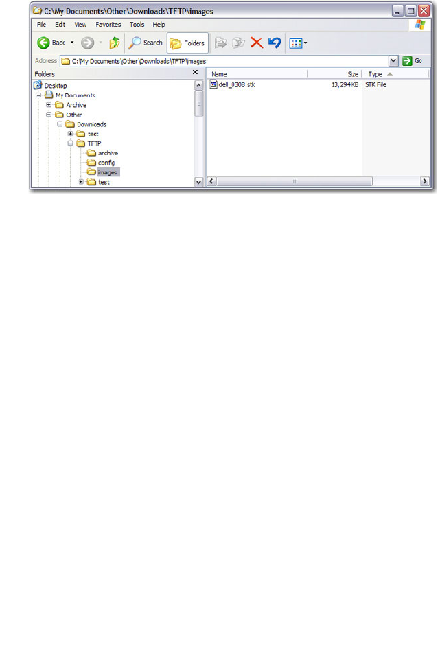
382 Managing Images and Files
Figure 14-9. Image Path
3
View information about the current image.
console#show version
Image Descriptions
image1 :default image
image2 :
Images currently available on Flash
4
Download the image to the switch. After you execute the
copy
command,
you must verify that you want to start the download.
The downloaded image replaces the currently inactive image, which may
be image1 or image2.Use either the
active
or
backup
keyword to have the
image to replace the specified image type (which takes effect only after a
reboot). In the following example, the active image is replaced.
console#copy
tftp://10.27.65.103/images/dell_0308.stk
imageactive
Mode........................................... TFTP
------- ------------ ------------ --------------- --------------
unit image1 image2 current-active next-active
------- ------------ ------------ --------------- --------------
1 4.1.0.7 5.0.0.8 image1 image1

Managing Images and Files 383
Set TFTP Server IP............................. 10.27.65.103
TFTP Path...................................... images/
TFTP Filename.................................. dell_0308.stk
Data Type...................................... Code
Destination Filename........................... image
Management access will be blocked for the duration of the
transfer
Are you sure you want to start? (y/n)y
5
Activate the new image (image2) so that it becomes the active image after
the switch resets.
Use either the
active
or
backup
keyword, depending on which file type you
selected for replacement in step 4.
console#boot system activeimage2
Activating image activeimage2..
6
View information about the current image.
console#show bootvar
Image Descriptions
image1 :
image2 :
Images currently available on Flash
7
Copy the running configuration to the startup configuration to save the
current configuration to NVRAM.
console#copy running-config startup-config
This operation may take a few minutes.
Management interfaces will not be available during
this time.
Are you sure you want to save? (y/n)y
------- ------------ ------------ --------------- --------------
unit image1 image2 current-active next-active
------- ------------ ------------ --------------- --------------
1 4.1.0.7 5.0.0.8 image1 image2
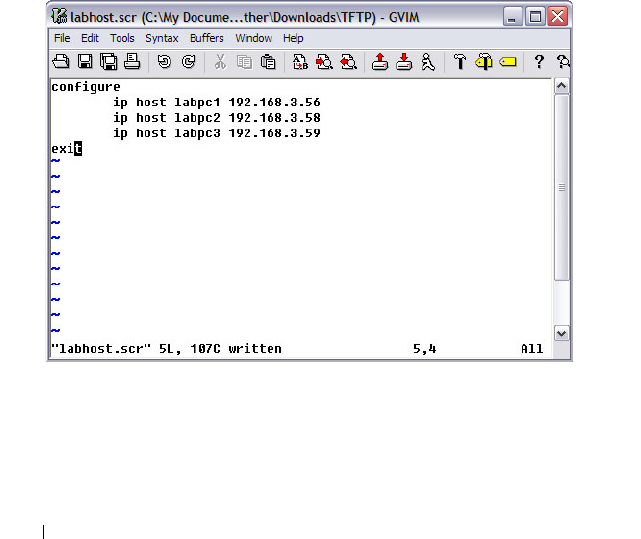
384 Managing Images and Files
Configuration Saved!
8
Reset the switch to boot the system with the new image.
console#reload
Are you sure you want to continue? (y/n)y
Reloading all switches...
Managing Configuration Scripts
This example shows how to create a configuration script that adds three
hostname-to-IP address mappings to the host table.
To configure the switch:
1
Open a text editor on an administrative computer and type the commands
as if you were entering them by using the CLI.
Figure 14-10. Create Config Script
2
Save the file with an *.scr extension and copy it to the appropriate
directory on your TFTP server.
3
Download the file from the TFTP server to the switch.

Managing Images and Files 385
console#copy tftp://10.27.65.103/labhost.scr
script labhost.scr
Mode........................................... TFTP
Set TFTP Server IP............................. 10.27.65.103
TFTP Path...................................... ./
TFTP Filename.................................. labhost.scr
Data Type...................................... Config Script
Destination Filename........................... labhost.scr
Management access will be blocked for the duration of the
transfer
4
After you confirm the download information and the script successfully
downloads, it is automatically validated for correct syntax.
Are you sure you want to start? (y/n) y
135 bytes transferred
Validating configuration script...
configure
exit
configure
ip host labpc1 192.168.3.56
ip host labpc2 192.168.3.58
ip host labpc3 192.168.3.59
Configuration script validated.
File transfer operation completed successfully.
5
Run the script to execute the commands.
console#script apply labhost.scr
Are you sure you want to apply the configuration
script? (y/n)y
configure
exit
configure
ip host labpc1 192.168.3.56

386 Managing Images and Files
ip host labpc2 192.168.3.58
ip host labpc3 192.168.3.59
Configuration script 'labhost.scr' applied.
6
Verify that the script was successfully applied.
console#show hosts
Host name: test
Name/address lookup is enabled
Name servers (Preference order): 192.168.3.20
Configured host name-to-address mapping:
Host Addresses
------------------------ ------------------------
labpc1 192.168.3.56
labpc2 192.168.3.58
labpc3 192.168.3.59
Managing Files by Using the USB Flash Drive
In this example, the administrator copies the backup image to a USB flash
drive before overwriting the backup image on the switch with a new image.
The administrator also makes a backup copy of the running-config by
uploading it to a USB flash drive. After the backups are performed, the
administrator downloads a new image from the USB flash drive to the switch
to prepare for the upgrade.
This example assumes the new image is named new_img.stk and has already
been copied from an administrative host onto the USB flash drive.
To configure the switch:
1
Insert the USB flash drive into the USB port on the front panel of the
switch. The USB flash drive is automatically mounted.
2
Copy the backup image from the switch to the USB flash drive.
console#copy image usb://img_backup.stk
Mode................................... unknown

Managing Images and Files 387
Data Type.............................. Code
Management access will be blocked for the duration
of the transfer
Are you sure you want to start? (y/n) y
3
Copy the running-config to the USB flash drive.
console#copy running-config usb://rc_backup.scr
Mode............................. unknown
Data Type........................ Config Script
Source Filename.................. temp-config.scr
Management access will be blocked for the duration
of the transfer
Are you sure you want to start? (y/n) y
4
Download the new image from the USB flash drive to the switch. The
image overwrites the image that is not currently active.
console#copy usb://new_image.stk image
Mode................................... unknown
Data Type.............................. Code
Management access will be blocked for the duration
of the transfer
Are you sure you want to start? (y/n) y
5
To activate the new image after it has been successfully downloaded to the
switch, follow the procedures described in Upgrading the Firmware,
starting with step 5.

388 Managing Images and Files

Auto Image and Configuration Update 389
15
Automatically Updating the Image
and Configuration
The topics covered in this chapter include:
• Auto Configuration Overview
• What Are the Dependencies for DHCP Auto Configuration?
• Default Auto Configuration Values
• Managing Auto Configuration (Web)
• Managing Auto Configuration (CLI)
• Auto Configuration Example
Auto Configuration Overview
The Auto Configuration feature can automatically update the firmware
image and obtain configuration information when the switch boots. Auto
Configuration begins the automatic download and installation process when
the switch or stack master is initialized and no configuration file (startup-
config) is found, or when the switch boots and loads a saved configuration
that has Auto Configuration enabled. Auto Configuration is enabled by
default. Allow downgrade is also enabled by default.
The Auto Configuration feature includes two components:
• USB Auto Configuration
•DHCP Auto Install
If no configuration file is found and the Auto Configuration feature is
enabled (which it is by default), the Auto Configuration process begins. If a
USB device is connected to the Dell Networking switch USB port and
contains the appropriate file, the switch uses the USB Auto Configuration
feature to update the configuration or image. If the USB Auto Configuration

390 Auto Image and Configuration Update
fails - either because it is disabled, no USB storage device is present, or no
configuration or images files are present on the USB storage device, the
switch uses the DHCP Auto Install process.
What Is USB Auto Configuration?
You can use the USB Auto Configuration feature to configure or upgrade one
or more switches that have not been previously configured, such as when you
deploy new switches. Before you deploy the switch, you perform the following
steps:
1
Create a text file that contains IP addresses (and/or MAC addresses) and
file names that are parsed and used by this feature. The optional MAC
address used to identify the switch is the MAC address of the base MAC
address of the switch, although the feature will accept any of the switch
MAC addresses (see "Switch MAC Addresses" on page 125 for further
information). The IP address is a required field in the configuration file.
Refer to the example below for an explanation of the file format.
2
Copy the file onto a USB device, along with any desired switch firmware
and configuration files.
3
Insert the USB device into the front-panel USB port on the Dell
Networking switch.
When the Auto Configuration process starts and no startup-config file is
present on the switch, the feature automatically searches a plugged-in USB
device for information.
What Files Does USB Auto Configuration Use?
The USB Auto Configuration feature uses the following file types:
• *.setup file for initial switch configuration
• *.text file for configuration information
• *.stk file for software image installation
The Auto Configuration file searches the USB device for a file with a *.setup
extension. If only one .setup file is present, the switch uses the file. When
multiple *.setup files are present, the switch uses only the dellswitch.setup
NOTE: Neither USB Configuration nor Auto Install is invoked if a valid
configuration file is on the switch.

Auto Image and Configuration Update 391
file. If no dellswitch.setup file is available, the switch checks for a file with a
*.text configuration file and a *.stk image file. If multiple .text files exist, the
switch uses the dellswitch.text file. If multiple *.stk files are present, the
switch uses the image with the highest (most recent) version. Finally, if no
*.setup, *.text, or *.stk files are found, the switch proceeds to the DHCP
Auto Configuration process.
How Does USB Auto Configuration Use the Files on the USB Device?
The *.setup file can include the following information:
• MAC address of the switch (optional)
• Configuration file name (optional)
• Image file name (optional)
• IP address (mandatory)
MAC Address Lookup
The MAC address should be on the same line as the configuration file and/or
image file name to allow a specific switch (identified by its MAC address) to
be associated with a specific config file or image. If an IP address also exists
on the line, this indicates a previous binding and requires this IP address to be
configured for the management IP address.
IP Address Lookup
If the switch MAC address is not found within the .setup text file, the first
line that contains an IP address and no MAC address and is not marked in-use
will be used by the switch to assign the management IP address/netmask. The
IP address line should include the configuration filename and/or image
filename for the switch. This method allows a group of IP addresses to be
handed out without regard to the specific switch identified by the MAC
address. A switch will mark a line as invalid if it is read and failed to properly
parse if, for example, it contains an invalid configuration, a duplicate IP
address or an image file name that is not available. Once a switch selects an IP
address from the file, it adds its MAC address to the line, marks the line as in-
use, and updates the file on the USB device.
If the *.setup file contains IP addresses but no file names, the management IP
address will be assigned, and then the feature will search the USB device for
files with the .text and .stk extensions, which indicates that all switches will

392 Auto Image and Configuration Update
be using the same configuration file and/or image on the USB device. This
method allows different IP addresses to be assigned, but the same
configuration file or image is downloaded to multiple switches.
After the current switch has been configured and/or upgraded and the
completion message is displayed on the switch, the current line in the *.setup
text file will be marked as used. This allows you to use the *.setup file for
additional switches without manually changing the file. You can then remove
the USB device and insert it into the next switch to begin the process again.
Also, the switch MAC address of the switch that has been automatically
configured is added to the beginning of the line (if no MAC address was
specified in the file) for lines using the IP address lookup method so that the
MAC and IP address combinations are recorded within the *.setup file for
future use bindings.
At the start of the next USB auto download, if all lines in the *.setup file are
marked as already “in-use” or “invalid,” and there is no MAC address match
for a switch, the process will halt, and a message similar to the following is
displayed on the console:
<###> APR 22 08:32:43 Error: Auto Configuration has
terminated due to there being no more lines available
for use within the USB file “XXXXX.setup”.
Configuration File
The *.text configuration file identified in the *.setup file contains the
running-config to be loaded on to the switch. The configuration file specified
in the *.setup file should exist on the USB device. For information about the
format and contents of the *.text file, see Editing and Downloading
Configuration Files.
Image File
If the Auto Configuration process includes a switch image upgrade, the name
of the image file should be included in the *.setup file. The specified image
file should exist on the USB device.
What Is the Setup File Format?
The setup file must have a *.setup extension or this part of the feature will
never begin. If there are multiple .setup files located on the USB device, the
dellswitch.setup file will take precedence.

Auto Image and Configuration Update 393
The general format of the configuration file lines is as follows. The IP address
and subnet mask are required. The MAC address, configuration file, and
image file name entries are optional.
MAC_address IP_Address Subnet_Mask Config_File Image_File
The following example shows a *.setup example for two switches:
2180.c200.0010 192.168.0.10 255.255.255.0 switch-A.text N2000vR.5.4.1.stk
3380.c200.0011 192.168.0.11 255.255.255.0 switch-B.text N2000vR.5.4.1.stk
After a line has been read and implemented by the Auto Configuration
feature, it automatically adds “in-use” to the end of the line to ensure that the
information is not used for the next switch. To replicate the entire USB auto
configuration process, the “in-use” statements from the .setup file need to be
removed. Then, if the process is restarted, the MAC address/IP address
combinations will be ensured for any switch that has previously attempted
upgrade and all other switch upgrades can take place as if for the first time.
What Is the DHCP Auto Configuration Process?
If the USB Auto Configuration fails or is not used, the switch can use a
DHCP server to obtain configuration information from a TFTP server.
DHCP Auto Configuration is accomplished in three phases:
1
Assignment or configuration of an IP address for the switch
2
Assignment of a TFTP server
3
Obtaining a configuration file for the switch from the TFTP server
Auto Configuration is successful when an image or configuration file is
downloaded to the switch or stack master from a TFTP server.
NOTE: The downloaded configuration file is not automatically saved to startup-
config. You must explicitly issue a save request (copy running-config startup-
config) in order to save the configuration.

394 Auto Image and Configuration Update
Obtaining IP Address Information
DHCP is enabled by default on the Out-of-Band (OOB) interface on N3000
and N4000 switches. DHCP is enabled by default on VLAN 1 on the N2000
switches. If an IP address has not been assigned, the switch issues requests for
an IP address assignment.
A network DHCP server returns the following information:
• IP address and subnet mask to be assigned to the interface
• IP address of a default gateway, if needed for IP communication
After an IP address is assigned to the switch, if a hostname is not already
assigned, Auto Configuration issues a DNS request for the corresponding
hostname. This hostname is also displayed as the CLI prompt (as in response
to the hostname command).
Obtaining Other Dynamic Information
The following information is also processed and may be returned by a
BOOTP or DHCP server:
• Name of configuration file (the
file
field in the DHCP header or option
67) to be downloaded from the TFTP server.
• Identification of the TFTP server providing the file. The TFTP server can
be identified by name or by IP address as follows:
– hostname: DHCP option 66 or the
sname
field in the DHCP header)
– IP address: DHCP option 150 or the
siaddr
field in the DHCP header
When a DHCP OFFER identifies the TFTP server more than once, the
DHCP client selects one of the options in the following order:
sname
, option
66, option 150,
siaddr
. If the TFTP server is identified by hostname, a DNS
server is required to translate the name to an IP address.
The DHCP client on the switch also processes the name of the text file
(option 125, the V-I vendor-specific Information option) which contains the
path to the image file.

Auto Image and Configuration Update 395
Obtaining the Image
Auto Configuration attempts to download an image file from a TFTP server
only if no configuration file was found in the internal flash or a USB drive, or
even with a saved configuration file that has Auto Configuration enabled.
The network DHCP server may return a DHCP OFFER message with option
125. When configuring the network DHCP server for image downloads, you
must include Option 125 and specify the Dell Enterprise Number, 674.
Within the Dell section of option 125, sub option 5 must specify the path and
name of a file on the TFTP server. This file is not the image file itself, but
rather a text file that contains the path and name of the image file. Upon
receipt of option 125, the switch downloads the text file from the TFTP
server, reads the name of the image file, and downloads the image file from
the TFTP server.
After the switch successfully downloads and installs the new image, it
automatically reboots. The download or installation might fail for one of the
following reasons:
• The path or filename of the image on the TFTP server does not match the
information specified in DHCP option 125.
• The downloaded image is the same as the current image.
• The validation checks, such as valid CRC Checksum, fails.
If the download or installation was unsuccessful, a message is logged.
Obtaining the Configuration File
If the DHCP OFFER identifies a configuration file, either as option 67 or in
the
file
field of the DHCP header, the switch attempts to download the
configuration file.
NOTE: In stack of switches, the downloaded image is pushed to all members
attached to the stack at the time of download. For members who join the stack
after the download, the Stack Firmware Synchronization feature will push the
latest image to all members.
NOTE: The configuration file is required to have a file type of *.cfg.

396 Auto Image and Configuration Update
The TFTP client makes three unicast requests. If the unicast attempts fail, or
if the DHCP OFFER did not specify a TFTP server address, the TFTP client
makes three broadcast requests.
If the DHCP server does not specify a configuration file or download of the
configuration file fails, the Auto Configuration process attempts to download
a configuration file with the name dell-net.cfg. The switch unicasts or
broadcasts TFTP requests for a network configuration file in the same
manner as it attempts to download a host-specific configuration file.
The default network configuration file consists of a set of IP address-to-
hostname mappings, using the command ip host hostname
address
. The
switch finds its own IP address, as learned from the DHCP server, in the
configuration file and extracts its hostname from the matching command. If
the default network configuration file does not contain the switch's IP
address, the switch attempts a reverse DNS lookup to resolve its hostname.
A sample dell-net.cfg file follows:
config
...
ip host switch1 192.168.1.10
ip host switch2 192.168.1.11
... <other hostname definitions>
exit
Once a hostname has been determined, the switch issues a TFTP request for
a file named hostname.cfg , where hostname is the first thirty-two
characters of the switch's hostname.
If the switch is unable to map its IP address to a hostname, Auto
Configuration sends TFTP requests for the default configuration file
host.cfg.

Auto Image and Configuration Update 397
Table 15-1 summarizes the config files that may be downloaded and the order
in which they are sought.
Table 15-2 displays the determining factors for issuing unicast or broadcast
TFTP requests.
Table 15-1. Configuration File Possibilities
Order
Sought
File Name Description Final File
Sought
1bootfile.cfg Host-specific config file, ending in a
*.cfg file extension
Yes
2dell-net.cfg Default network config file No
3hostname.cfg Host-specific config file, associated
with hostname.
Yes
4host.cfg Default config file Yes
Table 15-2. TFTP Request Types
TFTP Server
Address
Available
Host-specific Switch
Config Filename
Available
TFTP Request Method
Yes Yes Issue a unicast request for the host-specific
router config file to the TFTP server
Yes No Issue a unicast request for a default network
or router config file to the TFTP server
No Yes Issue a broadcast request for the host-
specific router config file to any available
TFTP server
No No Issue a broadcast request for the default
network or router config file to any available
TFTP server

398 Auto Image and Configuration Update
Monitoring and Completing the DHCP Auto Configuration Process
When the switch boots and triggers an Auto Configuration, a message
displays on the console screen to indicate that the process is starting. After
the process completes, the Auto Configuration process writes a log message.
When Auto Configuration has successfully completed, you can execute a
show running-config command to validate the contents of configuration.
Saving a Configuration
The Auto Configuration feature includes an AutoSave capability that allows
the downloaded configuration to be automatically saved; however, AutoSave
is disabled by default. If AutoSave has not been enabled, you must explicitly
save the downloaded configuration in nonvolatile memory on the stack
master. This makes the configuration available for the next reboot. In the
CLI, this is performed by issuing a write command or copy running-config
startup-config command and should be done after validating the contents of
saved configuration.
Stopping and Restarting the Auto Configuration Process
You can terminate the Auto Configuration process at any time before the
image or configuration file is downloaded. This is useful when the switch is
disconnected from the network. Termination of the Auto Configuration
process ends further periodic requests for a host-specific file.
The Auto Configuration process automatically starts after a reboot if the
configuration file is not found on the switch. The configuration file will not
be found if it has never been saved on the switch, or if you issue a command
to erase the configuration file (clear config or erase startup-config).
Managing Downloaded Config Files
The configuration files downloaded by Auto Configuration are stored in the
nonvolatile memory as .scr files. The files may be managed (viewed or
deleted) along with files downloaded by the configuration scripting utility.
A file is not automatically deleted after it is downloaded. The file does not
take effect upon a reboot unless you explicitly save the configuration (the
saved configuration takes effect upon reboot). If you do not save the
configuration downloaded by the Auto Configuration feature, the Auto
Configuration process occurs again on a subsequent reboot. This may result
in one of the previously downloaded files being overwritten.

Auto Image and Configuration Update 399
What Are the Dependencies for DHCP Auto Configuration?
The Auto Configuration process from TFTP servers depends upon the
following network services:
• A DHCP server must be configured on the network with appropriate
services.
• An image file and a text file containing the image file name for the switch
must be available from a TFTP server if DHCP image download is desired.
• A configuration file (either from bootfile (or) option 67 option) for the
switch must be available from a TFTP server.
• The switch must be connected to the network and have a Layer 3 interface
that is in an UP state.
• A DNS server must contain an IP address to hostname mapping for the
TFTP server if the DHCP server response identifies the TFTP server by
name.
• A DNS server must contain an IP address to hostname mapping for the
switch if a <
hostname>.cfg
file is to be downloaded.
• If a default gateway is needed to forward TFTP requests, an IP helper
address for TFTP needs to be configured on the default gateway.

400 Auto Image and Configuration Update
Default Auto Configuration Values
Table 15-3 describes the Auto Configuration defaults.
Table 15-3. Auto Configuration Defaults
Feature Default Description
Auto Install
Mode
Enabled When the switch boots and no saved configuration is
found, the Auto Configuration automatically begins.
Retry Count 3 When the DHCP or BootP server returns information
about the TFTP server and bootfile, the switch makes
three unicast TFTP requests for the specified bootfile. If
the unicast attempts fail or if a TFTP server address was
not provided, the switch makes three broadcast requests
to any available TFTP server for the specified bootfile.
AutoSave Disabled If the switch is successfully auto-configured, the
running configuration is not saved to the startup
configuration.
AutoReboot Enabled After an image is successfully downloaded during the
Auto Configuration process, the switch automatically
reboots and makes the downloaded image the active
image.
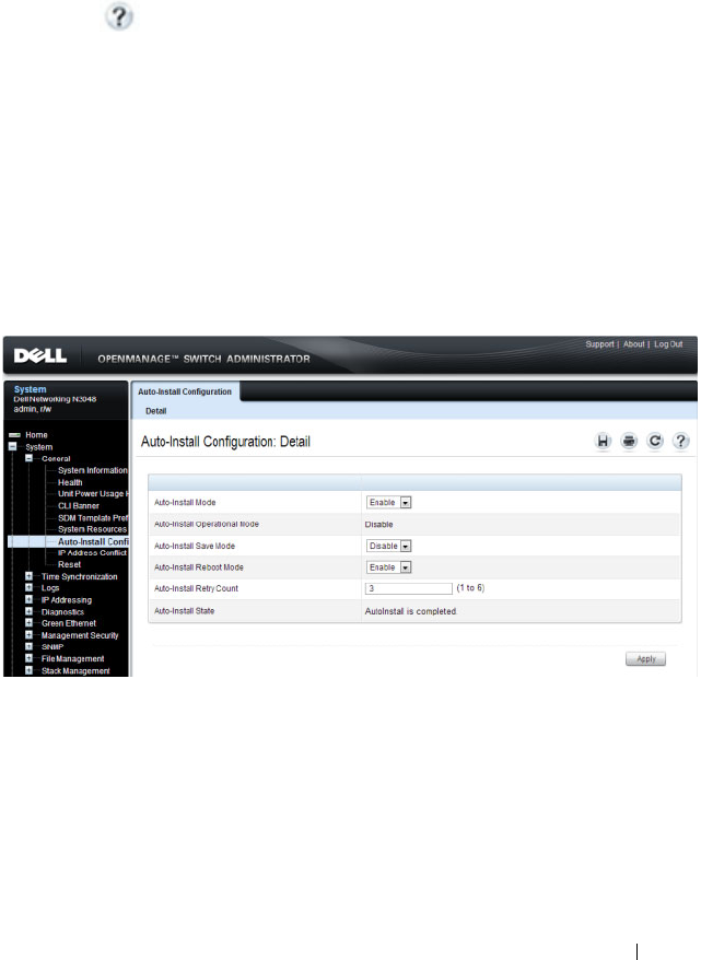
Auto Image and Configuration Update 401
Managing Auto Configuration (Web)
This section provides information about the OpenManage Switch
Administrator pages to use to manage images and files on a Dell Networking
N2000, N3000, and N4000 series switches. For details about the fields on a
page, click at the top of the page.
Auto-Install Configuration
Use the Auto-Install Configuration page to allow the switch to obtain
network information (such as the IP address and subnet mask) and
automatically download a host-specific or network configuration file during
the boot process if no startup-config file is found.
To display the Auto Configuration page, click System
→
General
→
Auto-
Install Configuration in the navigation panel.
Figure 15-1. Auto-Install Configuration

402 Auto Image and Configuration Update
Managing Auto Configuration (CLI)
This section provides information about the commands you manage the
Auto-Install Configuration feature on the switch. For more information about
these commands, see the
Dell Networking N2000, N3000, and N4000 Series
Switches CLI Reference Guide
at support.dell.com/manuals.
Managing Auto Configuration
Beginning in Privileged EXEC mode, use the following commands to
manually activate the Auto Configuration process and download a
configuration script from a remote system to the switch, validate the script,
and activate it.
NOTE: The Auto Configuration feature begins automatically when the switch is
booted and no startup-config file is found or if the system boots and finds the
boot host dhcp command in the startup-config file.
Command Purpose
configure Enter Global Configuration mode.
boot host dhcp Enable Auto Configuration for the next reboot cycle. The
command does not change the current behavior of Auto
Configuration, but it does save the command to NVRAM.
boot host auto-save Allow the switch to automatically save the configuration file
downloaded to the switch by the Auto Configuration feature.
boot host retry-count
retries
Specify the number of attempts to download the file (by
sending unicast TFTP requests, and if unsuccessful,
broadcast TFTP requests) specified in the response from the
DHCP server.
The range for
retries
is 1–3.
boot host auto-reboot Allow the switch to automatically reboot when the image is
successfully downloaded through the Auto Configuration
feature.
exit Exit to Privileged Exec mode.
show boot Displays the current status of the Auto Configuration process.

Auto Image and Configuration Update 403
Auto Configuration Example
A network administrator is deploying three Dell Networking switches and
wants to quickly and automatically install the latest image and a common
configuration file that configures basic settings such as VLAN creation and
membership, RADIUS server settings, and 802.1X information. The
configuration file also contains the command boot host autosave so that the
downloaded configuration is automatically saved to the startup config.
This section describes two ways to enable automatic configuration file
download:
• Enabling USB Auto Configuration and Auto Image Download
• Enabling DHCP Auto Configuration and Auto Image Download
Enabling USB Auto Configuration and Auto Image Download
This example describes how to deploy three switches and automatically install
a custom configuration file on the switch and upgrade each switch with the
latest software image by using the USB Auto Configuration feature. The
switches have the following MAC addresses:
• Switch A: 001E.C9AA.AC17
• Switch B: 001E.C9AA.AC20
• Switch C: 001E.C9AA.AC33
To configure each switch with a static IP address, you can include the IP
address in the .setup file or in the configuration file (.text) for the switch.
Otherwise, the switch can obtain an IP address from a DHCP server on the
network.
To use USB auto configuration:
1
Create a default config file for each switch. The configuration files are
named
switchA.txt
,
switchB.txt
, and
switchC.txt
. For
information about creating configuration files, see Managing Images and
Files.
2
Copy the configuration files to a USB device.
3
Copy the image file to the device. In this example, the image file that each
switch will download is named
N2000vR.5.4.1.stk
.

404 Auto Image and Configuration Update
4
Create a setup file named
dellswitch.setup
. The setup file contains
the following lines:
001E.C9AA.AC17 switchA.txt N2000vR.5.4.1.stk
001E.C9AA.AC20 switchB.txt N2000vR.5.4.1.stk
001E.C9AA.AC33 switchC.txt N2000vR.5.4.1.stk
5
Copy the
dellswitch.setup
file to the USB device.
6
Connect the USB device to Switch A.
7
Connect Switch A to the network. Make sure that a port (OOB port for
out-of-band management or any switch port for in-band management) is
connected to the network and that a DHCP server is accessible on the
network.
8
Insert the USB device into the USB port on the front panel of Switch A.
9
Power on Switch A. If no startup-config file is found, the Easy Startup
wizard will begin. Press N to skip the Easy Startup wizard and the USB
Auto Configuration process will begin. If necessary, delete the startup-
config file and reboot the switch.
The configuration in
switchA.txt
file is downloaded to the switch,
and the management interface acquires network information. After the
process completes, a message displays to indicate the status. The
dellswitch.setup
file is updated to add the term
in-use
to the
end of the line. The
N2000vR.5.4.1.stk
image is also downloaded
to the switch.
10
Remove the USB device from Switch A and insert it into Switch B.
11
Repeat the process to connect a port to the network. Power on the switch
to begin the USB Auto Configuration process on Switch B.
12
Remove the USB device from Switch B after the process completes, and
repeat the steps to perform the USB Auto Configuration process on
Switch C.
NOTE: This .setup file does not provide the switch with a static IP address.
However, the switchA.txt, switchB.txt, and switchC.txt
files can contain the commands required to configure a static IP address on
each switch. Otherwise, the switch will use DHCP to attempt to acquire an IP
address.

Auto Image and Configuration Update 405
Enabling DHCP Auto Configuration and Auto Image Download
If no USB device is connected to the USB port on the Dell Networking switch
and no configuration file is found during the boot process, the Auto
Configuration feature uses the DHCP Auto Configuration process to
download the configuration file to the switch. This example describes the
procedures to complete the configuration.
To use DHCP auto configuration:
1
Create a default config file for the switches named
host.cfg
. For
information about creating configuration files, see Managing Images and
Files.
2
Upload the
host.cfg
file to the TFTP server.
3
Upload the image file to the TFTP server.
4
Configure an address pool on the DHCP server that contains the following
information:
a
The IP address (
yiaddr
) and subnet mask (option 1) to be assigned to
the interface
b
The IP address of a default gateway (option 3)
c
DNS server address (option 6)
d
Name of config file for each host
e
Identification of the TFTP server by hostname (DHCP option 66 or
the
sname
field in the DHCP header) or IP address (DHCP option
150 or the
siaddr
field in the DHCP header)
f
Name of the text file (option 125, the V-I vendor-specific Information
option) that contains the path to the image file.
5
Connect a port (OOB port for out-of-band management or any switch port
for in-band management) on each switch to the network.
6
Boot the switches.

406 Auto Image and Configuration Update
Easy Image Upgrade via USB
If a USB device is detected during bootup and there is an image on the USB
device, and the switch has no startup config file, then the image version is
checked against the active image version. If a newer image version is found on
the USB device, the image is copied to the switch and the switch reloads
using the new image.
1
Copy the startup-config file to the backup-config,; e.g.,
copy startup-
config backup-config
.
2
Delete the startup-config file; e.g.,
del startup-config
.
3
Put the new image on a cleanly formatted USB stick and insert the USB
stick into the stack master.
4
Reboot the stack master and skip the Easy Startup configuration wizard by
pressing N when prompted.
5
After the upgrade completes, copy the backup-config to the startup-config,
remove the USB stick, and reload the stack. The startup configuration is
migrated to the new syntax when loaded into the running-config. Check
the running-config, make and necessary adjustments, and then save the
running-config into the startup-config.

Monitoring Switch Traffic 407
16
Monitoring Switch Traffic
This chapter describes sFlow features, Remote Monitoring (RMON), and
Port Mirroring features.
The topics covered in this chapter include:
• Traffic Monitoring Overview
• Default Traffic Monitoring Values
• Monitoring Switch Traffic (Web)
• Monitoring Switch Traffic (CLI)
• Traffic Monitoring Configuration Examples
Traffic Monitoring Overview
The switch maintains statistics about network traffic that it handles. It also
has embedded technology that collects and sends information about traffic to
other devices. Dell Networking series switches include support for flow-based
monitoring through sFlow and Remote Network Monitoring (RMON)
agents.
What is sFlow Technology?
sFlow is an industry standard technology for monitoring high-speed switched
and routed networks. Dell Networking N2000, N3000, and N4000 series
switches software has a built-in sFlow agent that can monitor network traffic
on each port and generate sFlow data to an sFlow receiver (also known as a
collector). sFlow helps to provide visibility into network activity, which
enables effective management and control of network resources. sFlow is an
alternative to the NetFlow network protocol, which was developed by Cisco
Systems. The switch supports sFlow version 5.
As illustrated in Figure 16-1, the sFlow monitoring system consists of sFlow
Agents (such as Dell Networking series switches) and a central sFlow receiver.
sFlow Agents use sampling technology to capture traffic statistics from
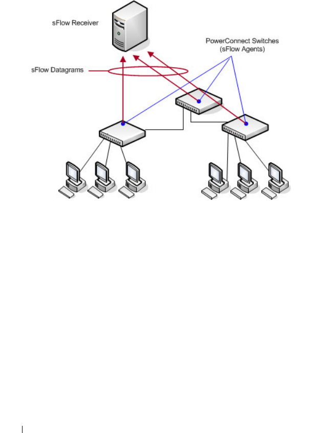
408 Monitoring Switch Traffic
monitored devices. sFlow datagrams forward sampled traffic statistics to the
sFlow Collector for analysis. You can specify up to eight different sFlow
receivers to which the switch sends sFlow datagrams.
Figure 16-1. sFlow Architecture
The advantages of using sFlow are:
• It is possible to monitor all ports of the switch continuously, with no
impact on the distributed switching performance.
• Minimal memory/CPU is required. Samples are not aggregated into a flow-
table on the switch; they are forwarded immediately over the network to
the sFlow receiver.
• The sFlow system is tolerant to packet loss in the network because
statistical modeling means the loss is equivalent to a slight change in the
sampling rate.
• sFlow receiver can receive data from multiple switches, providing a real-
time synchronized view of the whole network.
• The receiver can analyze traffic patterns based on protocols found in the
headers (e.g., TCP/IP, IPX, Ethernet, AppleTalk…). This alleviates the
need for a layer 2 switch to decode and understand all protocols.

Monitoring Switch Traffic 409
sFlow Sampling
The sFlow Agent in the Dell Networking software uses two forms of sampling:
• Statistical packet-based sampling of switched or routed Packet Flows
• Time-based sampling of counters
Packet Flow Sampling and Counter Sampling are performed by sFlow
Instances associated with individual Data Sources within an sFlow Agent.
Both types of samples are combined in sFlow datagrams. Packet Flow
Sampling creates a steady, but random, stream of sFlow datagrams that are
sent to the sFlow Collector. Counter samples may be taken opportunistically
to fill these datagrams.
To perform Packet Flow Sampling, an sFlow Sampler Instance is configured
with a Sampling Rate. Packet Flow sampling results in the generation of
Packet Flow Records. To perform Counter Sampling, an sFlow Poller Instance
is configured with a Polling Interval. Counter Sampling results in the
generation of Counter Records. sFlow Agents collect Counter Records and
Packet Flow Records and send them as sFlow datagrams to sFlow Collectors.
Packet Flow Sampling
Packet Flow Sampling, carried out by each sFlow instance, ensures that any
packet observed at a Data Source has an equal chance of being sampled,
irrespective of the Packet Flow(s) to which it belongs.
Packet Flow Sampling is accomplished as follows:
• A packet arrives on an interface.
• The Network Device makes a filtering decision to determine whether the
packet should be dropped.
• If the packet is not filtered (dropped) a destination interface is assigned by
the switching/routing function.
• A decision is made on whether or not to sample the packet.
The mechanism involves a counter that is decremented with each packet.
When the counter reaches zero a sample is taken.
• When a sample is taken, the counter indicating how many packets to skip
before taking the next sample is reset. The value of the counter is set to a
random integer where the sequence of random integers used over time is
the Sampling Rate.

410 Monitoring Switch Traffic
Counter Sampling
The primary objective of Counter Sampling is to efficiently, periodically
export counters associated with Data Sources. A maximum Sampling Interval
is assigned to each sFlow instance associated with a Data Source.
Counter Sampling is accomplished as follows:
• sFlow Agents keep a list of counter sources being sampled.
• When a Packet Flow Sample is generated the sFlow Agent examines the
list and adds counters to the sample datagram, least recently sampled first.
Counters are only added to the datagram if the sources are within a short
period, 5 seconds say, of failing to meet the required Sampling Interval.
• Periodically, say every second, the sFlow Agent examines the list of counter
sources and sends any counters that must be sent to meet the sampling
interval requirement.
The set of counters is a fixed set.
What is RMON?
Like sFlow, RMON is a technology that enables the collection and analysis of
a variety of data about network traffic. Dell Networking N2000, N3000, and
N4000 series switches software includes an RMON probe (also known as an
RMON agent) that collect information and analyze packets. The data that is
collected is defined in the RMON MIB, RFC 2819.
RMON is defined in an Internet Engineering Task Force (IETF) specification
and is an extension of the SNMP MIB. You can view the RMON information
locally on the switch or by using a generic RMON console on a network
management station (NMS). SNMP does not need to be configured on the
switch to view the RMON data locally. However, if you use a management
station to view the RMON data that the switch collects and analyzes, you
must configure the following SNMP settings:
• Set up the SNMP community string to be used by the SNMP manager at a
given IP address.
• Specify the network management system IP address or permit
management access from all IP addresses.
For more information about configuring SNMP, see "Configuring SNMP" on
page 323.

Monitoring Switch Traffic 411
The RMON agent in the switch supports the following groups:
• Group 1—Statistics. Contains cumulative traffic and error statistics.
• Group 2—History. Generates reports from periodic traffic sampling that
are useful for analyzing trends.
• Group 3 —Alarm. Enables the definition and setting of thresholds for
various counters. Thresholds can be passed in either a rising or falling
direction on existing MIB objects, primarily those in the Statistics group.
An alarm is triggered when a threshold is crossed and the alarm is passed to
the Event group. The Alarm requires the Event Group.
• Group 9 —Event. Controls the actions that are taken when an event
occurs. RMON events occur when:
– A threshold (alarm) is exceeded
– There is a match on certain filters.
What is Port Mirroring?
Port mirroring is used to monitor the network traffic that a port sends and
receives. The Port Mirroring feature creates a copy of the traffic that the
source port handles and sends it to a destination port. The source port is the
port that is being monitored. The destination port is where you would
connect a network protocol analyzer to learn more about the traffic that is
handled by the source port. Dell Networking switches support RSPAN
destinations where traffic can be tunneled across the operational network.
A port monitoring session includes one or more source ports that mirror
traffic to a single destination port. Sources can include VLANs, physical
interfaces, port-channels, the internal CPU port, or IP or MAC ACL flows.
Certain sources are not supported; i.e., physical members of a port-channel,
VLANs that contain a LAG member, etc. Destination ports, once configured,
no longer participate in spanning tree, IGMP/MLD snooping, or GVRP; do
not learn MAC addresses (learned MAC addresses are purged); do not
participate in routing (route entries are purged); and do not utilize any static
filter configuration. Configuration of a destination port is restored when the
port is no longer configured as a destination port.
NOTE: The switch supports RMON1.

412 Monitoring Switch Traffic
For each source port, you can specify whether to mirror ingress traffic (traffic
the port receives, or RX), egress traffic (traffic the port sends, or TX), or both
ingress and egress traffic.
The packet that is copied to the destination port is in the same format as the
original packet on the wire. This means that if the mirror port is copying a
received packet, the copied packet is VLAN tagged or untagged as it was
received on the source port. If the mirror is copying a transmitted packet, the
copied packet is VLAN tagged or untagged as it is being transmitted on the
source port. Destinations include physical interfaces and RSPAN VLANs.
After you configure the port mirroring session, you can enable or disable the
administrative mode of the session to start or stop the probe port from
receiving mirrored traffic.
Port Mirroring Behaviors
The following behaviors are applicable to monitor ports:
• The destination port loses its VLAN configuration when port mirroring is
enabled. The VLAN configuration is restored when the port is no longer
configured for a monitor session. The mirrored source and the transit ports
retain their VLAN configuration. Transit ports must be members of the
RSPAN VLAN.
• When port mirroring is enabled, all MAC address entries associated with
destination ports are purged. This prevents transmitting packets out of the
port that are not seen on the mirrored port. If spanning tree is enabled, this
is treated as a topology change.
• The spanning tree protocol is disabled on destination ports such that
frames are always received from or transmitted out of the port as soon as
the port is up (spanning tree status is forwarding and role is disabled). This
is analogous to always setting the spanning tree state of the port to
forwarding. When a port is no longer configured to be the destination
port, spanning tree is re-enabled for that port, if configured. Note that the
NOTE: You can create a DiffServ policy class definition or an ACL that mirrors
specific types of traffic to a destination port. For more information, see
"Configuring Differentiated Services" on page 1285 or "Configuring Access Control
Lists" on page 583.

Monitoring Switch Traffic 413
disabling of spanning tree on a destination port means that administrators
must only connect the destination port to directly attached probes to avoid
the possibility of a network loop.
• GVRP is disabled on destination ports such that GVRP PDUs are never
received from or transmitted to the port. Dynamic registrations are not
allowed on a destination port. The GVRP configuration at the port is
maintained and is reapplied when the port is no longer part of the SPAN.
• All static filters, both source and destination, are disabled on destination
ports.
• If routing is enabled on a destination port or an RSPAN VLAN, all route
entries associated with that port are purged. From a routing perspective,
the interface is marked as down.
• Generally, the configuration of the source port is undisturbed so that its
behavior remains the same as if it was not mirrored.
• Packets locally generated by the switch and transmitted over a source port
are not copied in a mirroring session.
• The internal CPU port is allowed as a source port for local monitoring
sessions only (not allowed for RSPAN). If the internal CPU port is
mirrored, packets received and generated by the CPU for all ports are
mirrored.
Remote Capture
The Remote Capture feature enables mirrorring packets transmitted and
received by the switch CPU to a remote client for packet analysis using the
Wireshark tool. This feature can be used to help diagnose switch behavior or
monitor traffic sent to the switch CPU. The capture feature can also be
configured to capture to a local file or to an in-memory buffer.
Why is Traffic Monitoring Needed?
Monitoring the traffic that the switch handles, as well as monitoring all traffic
in the network, can help provide information about network performance and
utilization. This information can be useful in network planning and resource
allocation. Information about traffic flows can also help troubleshoot
problems in the network.

414 Monitoring Switch Traffic
Default Traffic Monitoring Values
The sFlow agent is enabled by default, but sampling and polling are disabled
on all ports. Additionally, no sFlow receivers (collectors) are configured.
Table 16-1 contains additional default values for the sFlow feature.
RMON is enabled by default, but no RMON alarms, events, or history
statistic groups are configured.
Port mirroring is disabled, and no ports are configured as source or destination
ports. After you configure a port mirroring session, the administrative mode is
disabled until you explicitly enable it.
Monitoring Switch Traffic (Web)
This section provides information about the OpenManage Switch
Administrator pages to use to monitor network traffic on a Dell Networking
N2000, N3000, and N4000 series switches. For details about the fields on a
page, click at the top of the page.
sFlow Agent Summary
Use the sFlow Agent Summary page to view information about sFlow MIB
and the sFlow Agent IP address.
To display the Agent Summary page, click System
→
sFlow
→
Agent
Summary in the navigation panel.
Table 16-1. sFlow Defaults
Parameter Default Value
Receiver timeout for sampling 0
Receiver port 6343
Receiver Maximum Datagram Size 1400 bytes
Maximum header size 128 bytes
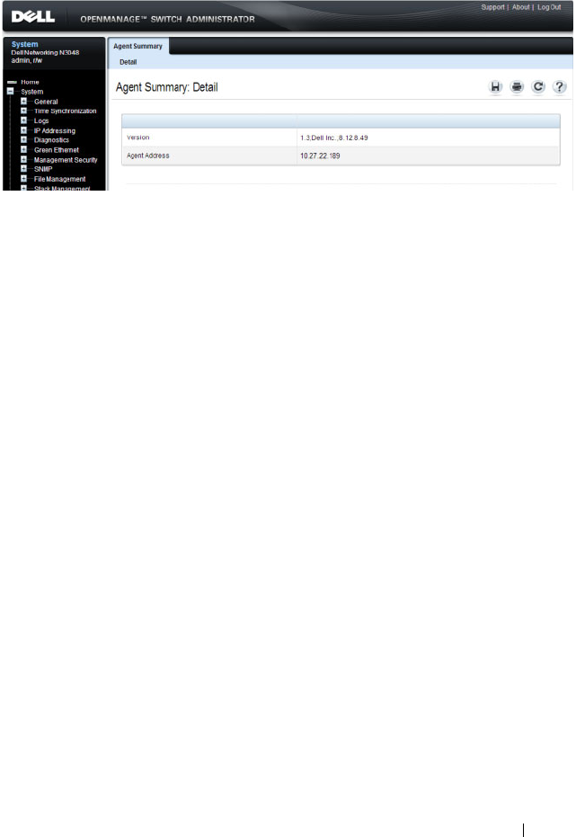
Monitoring Switch Traffic 415
Figure 16-2. sFlow Agent Summary

416 Monitoring Switch Traffic
sFlow Receiver Configuration
Use the sFlow Receiver Configuration page to configure settings for the
sFlow receiver to which the switch sends sFlow datagrams. You can configure
up to eight sFlow receivers that will receive datagrams.
To display the Receiver Configuration page, click System
→
sFlow
→
Receiver Configuration in the navigation panel.
Figure 16-3. sFlow Receiver Configuration
Click Show All to view information about configured sFlow receivers.
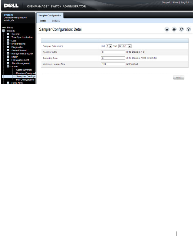
Monitoring Switch Traffic 417
sFlow Sampler Configuration
Use the sFLow Sampler Configuration page to configure the sFlow sampling
settings for switch ports.
To display the Sampler Configuration page, click System
→
sFlow
→
Sampler Configuration in the navigation panel.
Figure 16-4. sFlow Sampler Configuration
Click Show All to view information about configured sampler data sources.
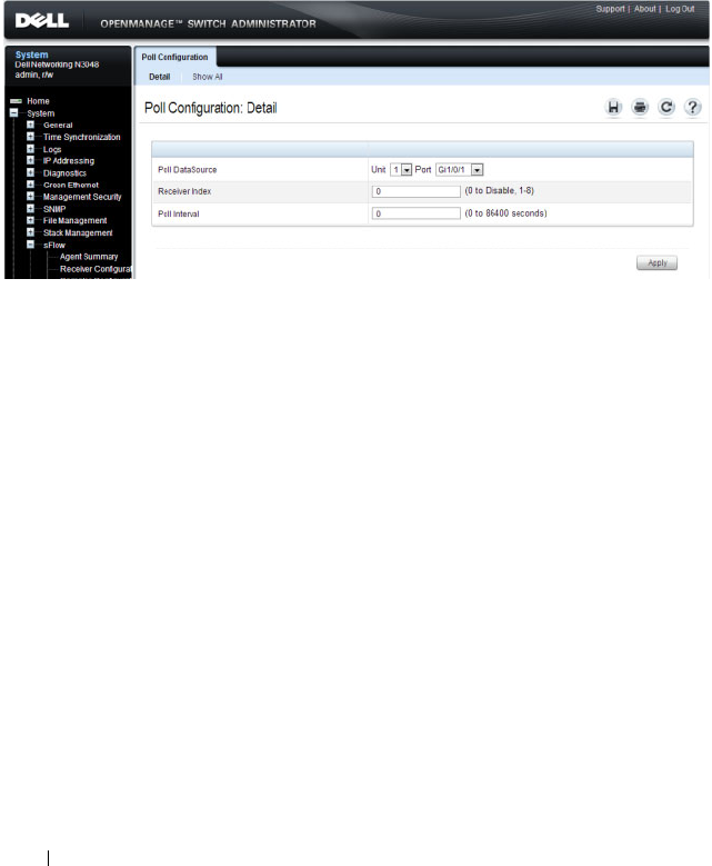
418 Monitoring Switch Traffic
sFlow Poll Configuration
Use the sFLow Poll Configuration page to configure how often a port should
collect counter samples.
To display the Sampler Configuration page, click System
→
sFlow
→
Sampler Configuration in the navigation panel.
Figure 16-5. sFlow Poll Configuration
Click Show All to view information about the ports configured to collect
counter samples.
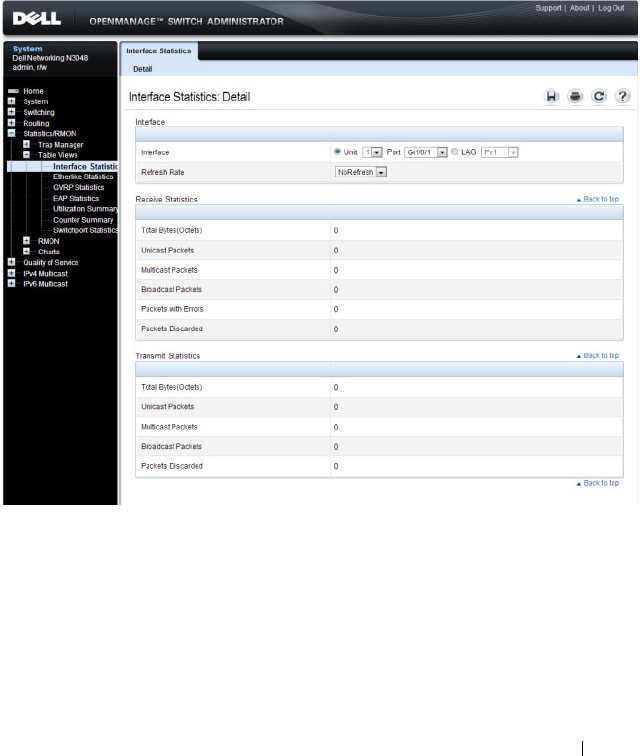
Monitoring Switch Traffic 419
Interface Statistics
Use the Interface Statistics
page to display statistics for both received and
transmitted packets. The fields for both received and transmitted packets are
identical.
To display the page, click Statistics/RMON
→
Table Views
→
Interface
Statistics in the navigation panel.
Figure 16-6. Interface Statistics
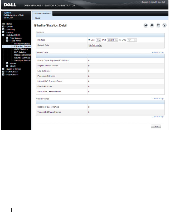
420 Monitoring Switch Traffic
Etherlike Statistics
Use the Etherlike Statistics page to display interface statistics.
To display the page, click Statistics/RMON
→
Table Vi ews
→
Etherlike
Statistics in the navigation panel.
Figure 16-7. Etherlike Statistics
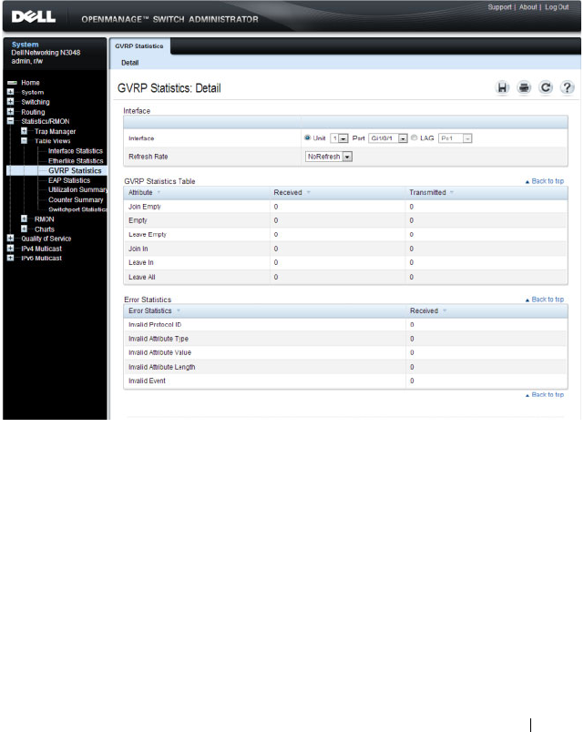
Monitoring Switch Traffic 421
GVRP Statistics
Use the
GVRP Statistics page to display switch statistics for GVRP.
To display the page, click Statistics/RMON
→
Table Views
→
GVRP
Statistics in the navigation panel.
Figure 16-8. GVRP Statistics
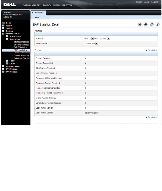
422 Monitoring Switch Traffic
EAP Statistics
Use the EAP Statistics page to display information about EAP packets
received on a specific port. For more information about EAP, see "Configuring
Port and System Security" on page 503.
To display the EAP Statistics page, click Statistics/RMON
→
Table Views
→
EAP Statistics in the navigation panel
.
Figure 16-9. EAP Statistics
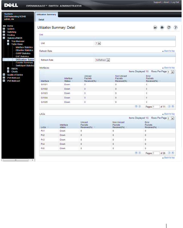
Monitoring Switch Traffic 423
Utilization Summary
Use the
Utilization Summary
page to display interface utilization statistics.
To display the page, click Statistics/RMON
→
Table Views
→
Utilization
Summary in the navigation panel.
Figure 16-10. Utilization Summary
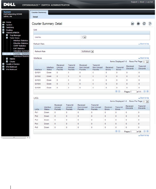
424 Monitoring Switch Traffic
Counter Summary
Use the
Counter Summary
page to display interface utilization statistics in
numeric sums as opposed to percentages.
To display the page, click Statistics/RMON
→
Table Vi ews
→
Counter
Summary in the navigation panel.
Figure 16-11. Counter Summary
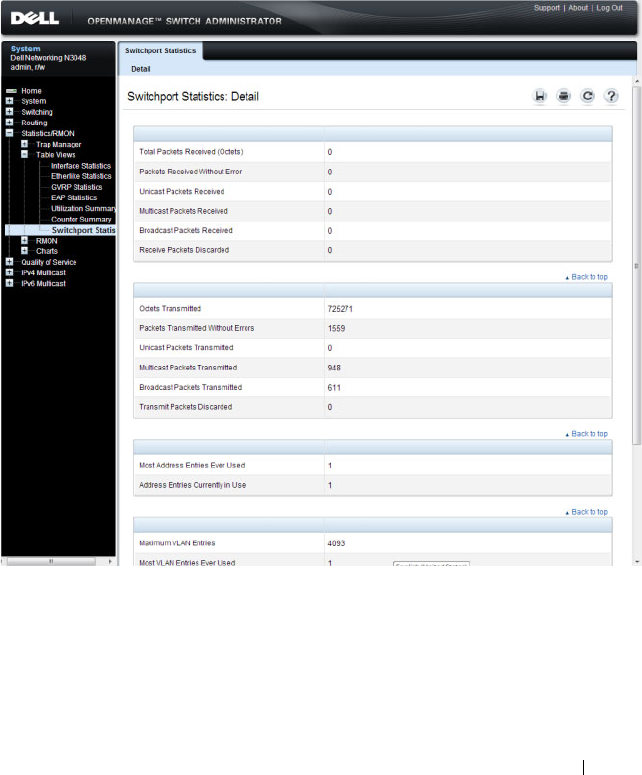
Monitoring Switch Traffic 425
Switchport Statistics
Use the
Switchport Statistics page to display statistical summary information
about switch traffic, address tables, and VLANs.
To display the page, click Statistics/RMON
→
Table Views
→
Switchport
Statistics in the navigation panel.
Figure 16-12. Switchport Statistics
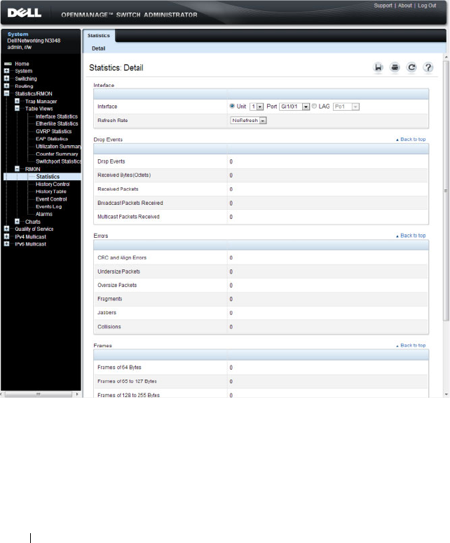
426 Monitoring Switch Traffic
RMON Statistics
Use the RMON Statistics page to display details about switch use such as
packet processing statistics and errors that have occurred on the switch.
To display the page, click Statistics/RMON
→
RMON
→
Statistics in the
navigation panel.
Figure 16-13. RMON Statistics
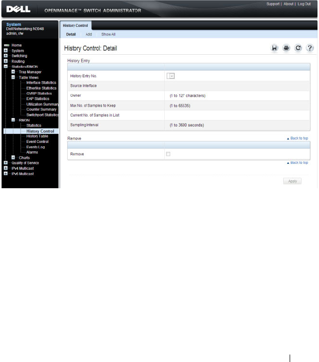
Monitoring Switch Traffic 427
RMON History Control Statistics
Use the RMON History Control page to maintain a history of statistics on
each port. For each interface (either a physical port or a port-channel), you
can define how many buckets exist, and the time interval between each
bucket snapshot.
To display the page, click Statistics/RMON
→
RMON
→
History Control in
the navigation panel.
Figure 16-14. RMON History Control
Adding a History Control Entry
To add an entry:
1
Open the
RMON History Control
page.
2
Click
Add
.
The
Add History Entry
page displays.

428 Monitoring Switch Traffic
Figure 16-15. Add History Entry
3
Select the port or LAG on which you want to maintain a history of
statistics.
4
Specify an owner, the number of historical buckets to keep, and the
sampling interval.
5
Click
Apply
to add the entry to the
RMON History Control Table
.
To view configured history entries, click the Show All tab. The
RMON
History Control Table
displays. From this page, you can remove configured
history entries.
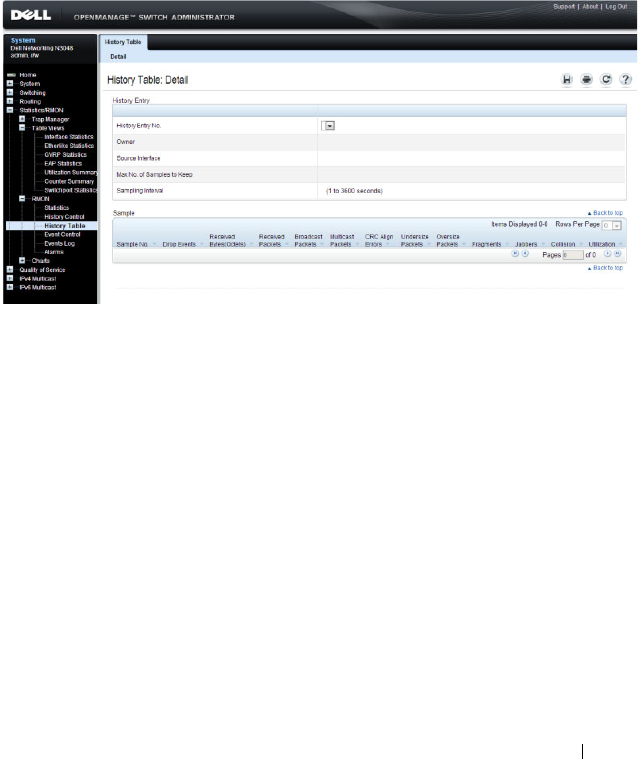
Monitoring Switch Traffic 429
RMON History Table
Use the RMON History Table page to display interface-specific statistical
network samplings. Each table entry represents all counter values compiled
during a single sample.
To display the RMON History Table page, click Statistics/RMON
→
RMON
→
History Table in the navigation panel.
Figure 16-16. RMON History Table
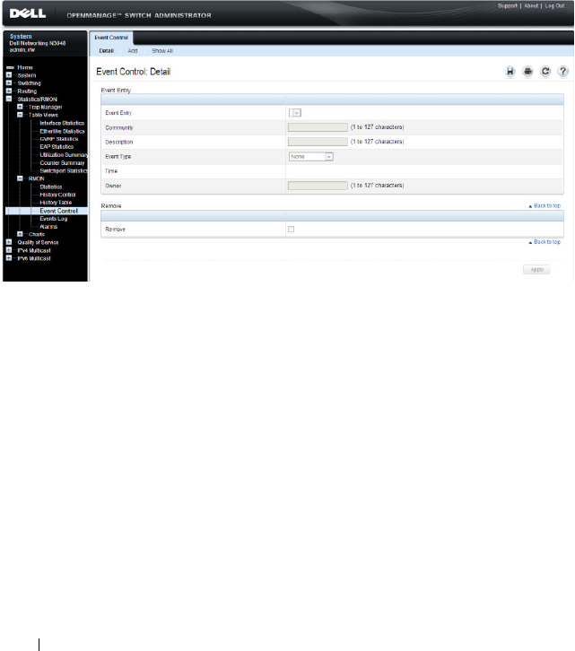
430 Monitoring Switch Traffic
RMON Event Control
Use the RMON Events Control page to define RMON events. Events are
used by RMON alarms to force some action when a threshold is crossed for a
particular RMON counter. The event information can be stored in a log
and/or sent as a trap to a trap receiver.
To display the page, click Statistics/RMON
→
RMON
→
Event Control in
the navigation panel.
Figure 16-17. RMON Event Control
Adding an RMON Event
To add an event:
1
Open the
RMON Event Control
page.
2
Click
Add
.
The
Add an Event Entry
page displays.
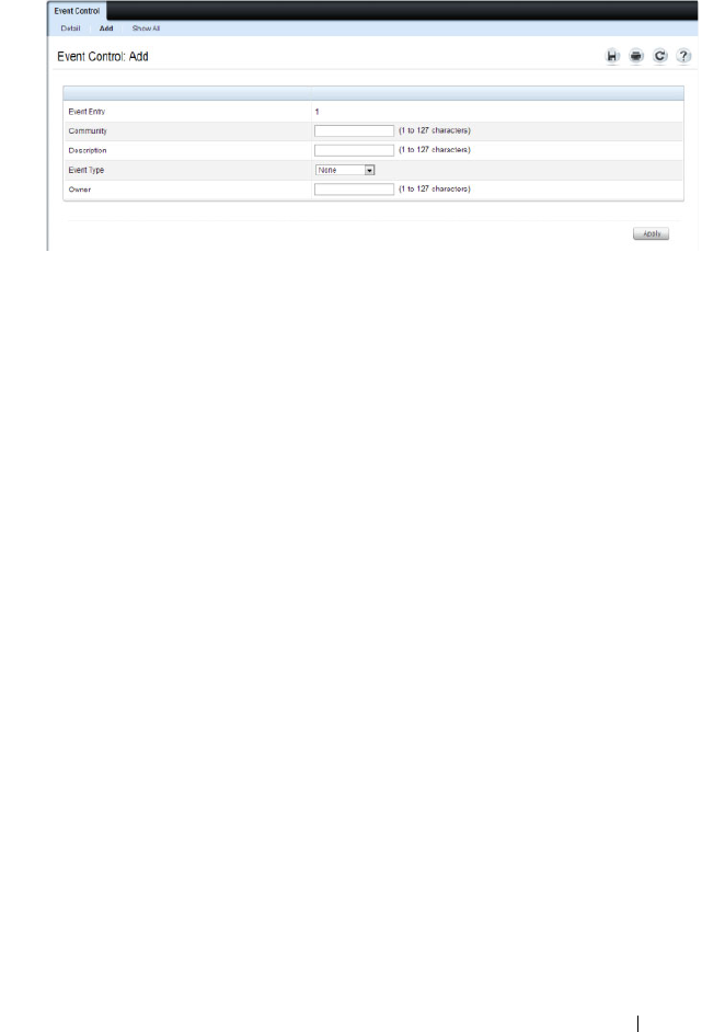
Monitoring Switch Traffic 431
Figure 16-18. Add an Event Entry
3
If the event sends an SNMP trap, specify the SNMP community to receive
the trap.
4
Optionally, provide a description of the event and the name of the event
owner.
5
Select an event type.
6
Click
Apply
.
The event is added to the
RMON Event Table
, and the device is updated.
Viewing, Modifying, or Removing an RMON Event
To manage an event:
1
Open the
RMON Event Control
page.
2
Click
Show All
to display the
Event Control Table
page.
3
To edit an entry:
a
Select the
Edit
check box in for the event entry to change.
b
Modify the fields on the page as needed.
4
To remove an entry, select the
Remove
check box in for the event entry to
remove.
5
Click
Apply
.
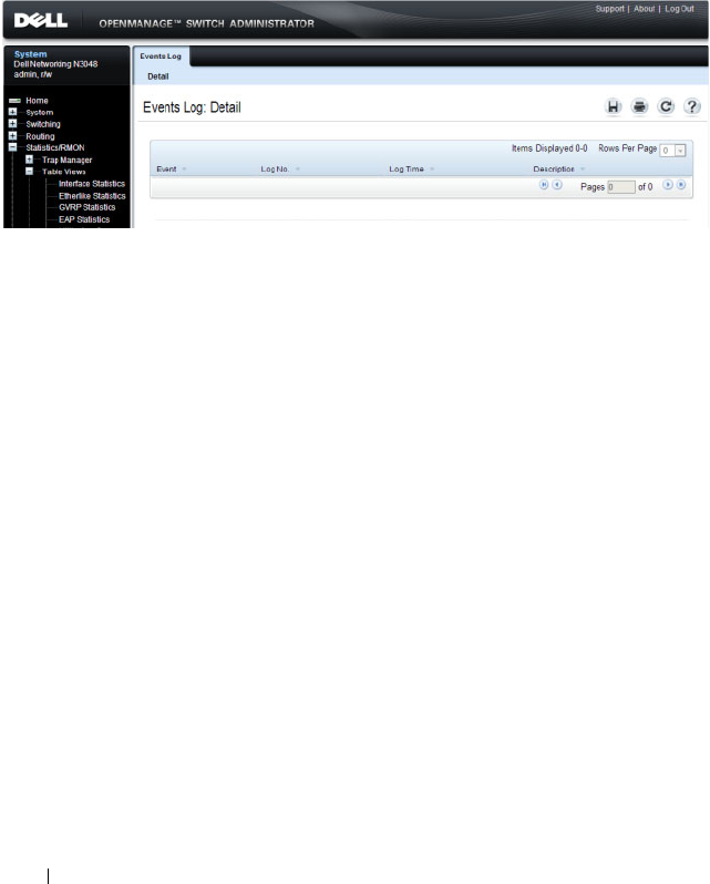
432 Monitoring Switch Traffic
RMON Event Log
Use the RMON Event Log page to display a list of RMON events.
To display the page, click Statistics/RMON
→
RMON
→
Events Log in the
navigation panel.
Figure 16-19. RMON Event Log
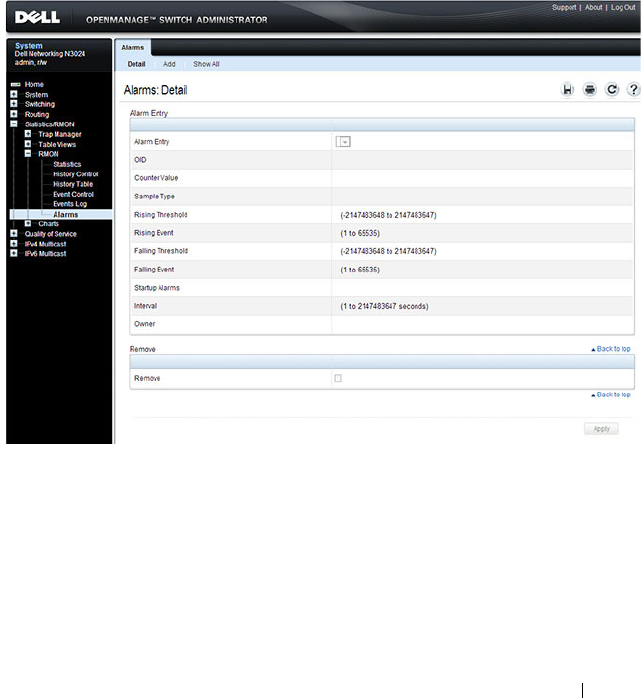
Monitoring Switch Traffic 433
RMON Alarms
Use the RMON Alarms page to set network alarms. Alarms occur when
certain thresholds are crossed for the configured RMON counters. The alarm
triggers an event to occur. The events can be configured as part of the RMON
Events group. For more information about events, see "RMON Event Log" on
page 432.
To display the page, click Statistics/RMON
→
RMON
→
Alarms in the
navigation panel.
Figure 16-20. RMON Alarms
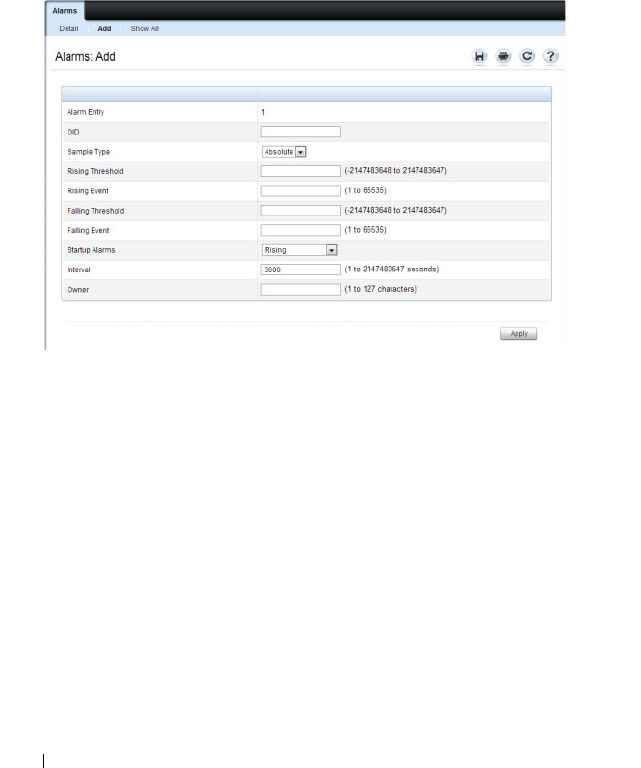
434 Monitoring Switch Traffic
Adding an Alarm Table Entry
To add an alarm:
1.
Open the
RMON Alarms
page.
2.
Click
Add.
The
Add an Alarm Entry
page displays.
Figure 16-21. Add an Alarm Entry
3.
Complete the fields on this page as needed. Use the help menu to learn
more information about the data required for each field.
4.
Click
Apply
.
The RMON alarm is added, and the device is updated.
To view configured alarm entries, click the Show All tab. The Alarms Table
displays. From this page, you can remove configured alarms.
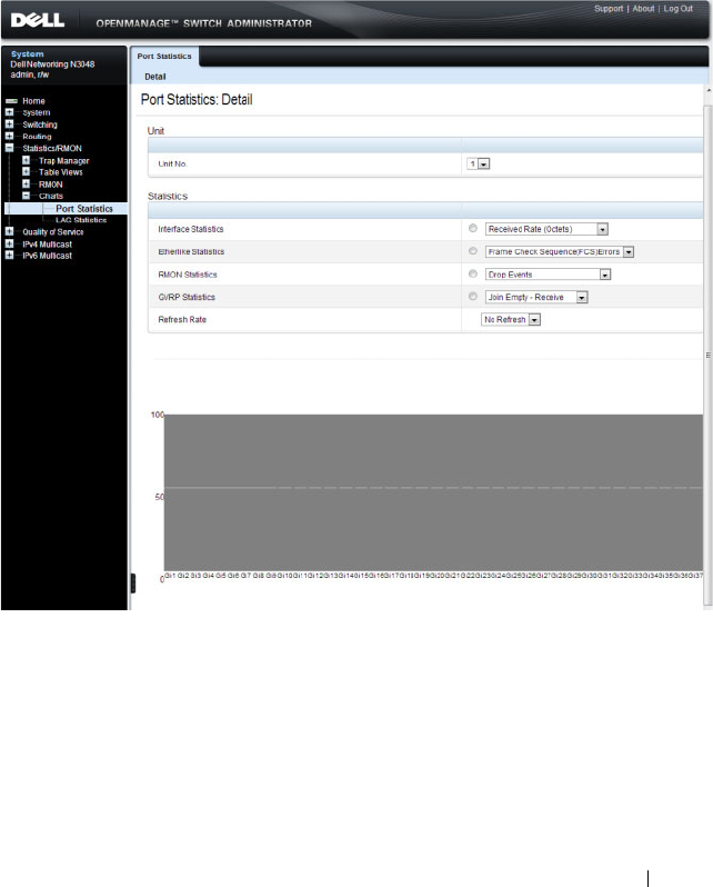
Monitoring Switch Traffic 435
Port Statistics
Use the Port Statistics
page to chart port-related statistics on a graph.
To display the page, click Statistics/RMON
→
Charts
→
Port Statistics in
the navigation panel.
Figure 16-22. Ports Statistics
To chart port statistics, select the type of statistics to chart and (if desired)
the refresh rate, then click Draw.
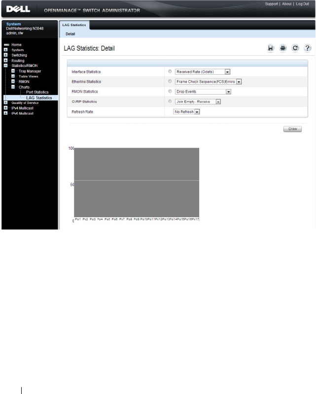
436 Monitoring Switch Traffic
LAG Statistics
Use the LAG Statistics page to chart LAG-related statistics on a graph.
To display the page, click Statistics/RMON
→
Charts
→
LAG Statistics in
the navigation panel.
Figure 16-23. LAG Statistics
To chart LAG statistics, select the type of statistics to chart and (if desired)
the refresh rate, then click Draw.
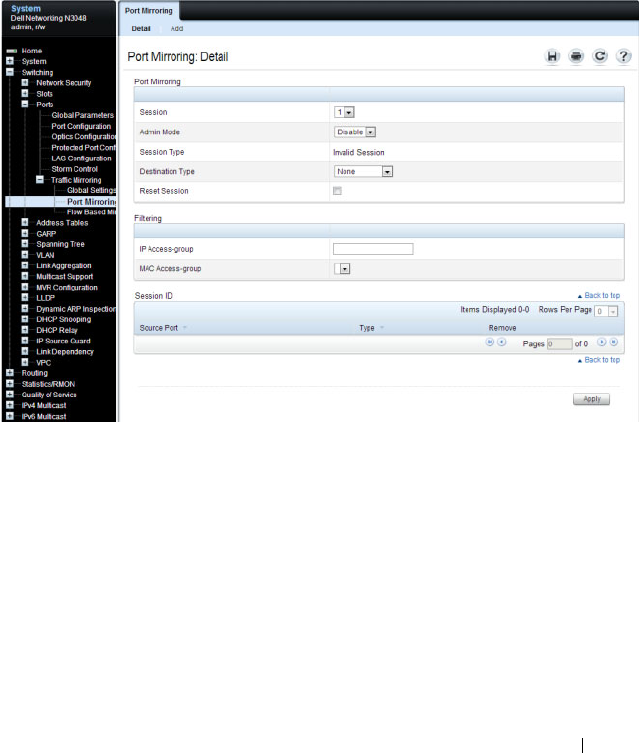
Monitoring Switch Traffic 437
Port Mirroring
Use the Port Mirroring page to create a mirroring session in which all traffic
that is sent or received (or both) on one or more source ports is mirrored to a
destination port.
To display the Port Mirroring page, click Switching
→
Ports
→
Traffic
Mirroring
→
Port Mirroring in the navigation panel.
Figure 16-24. Port Mirroring
Configuring a Port Mirror Session
To configure port mirroring:
1
Open the
Port Mirroring
page.
2
Click
Add
.
The
Add Source Port
page displays.
3
Select the port to be mirrored.
4
Select the traffic to be mirrored.
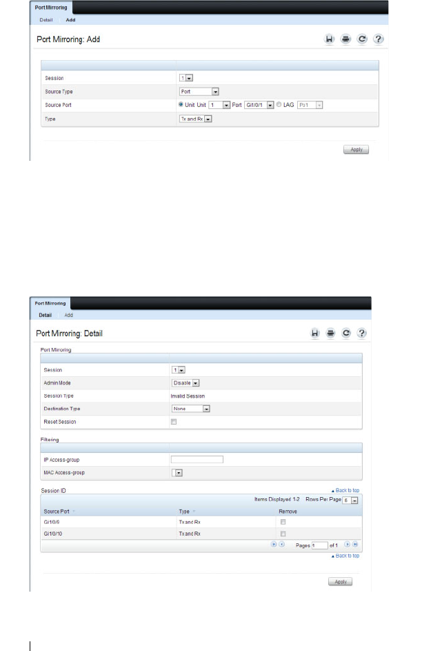
438 Monitoring Switch Traffic
Figure 16-25. Add Source Port
5
Click
Apply
.
6
Repeat the previous steps to add additional source ports.
7
Click
Port Mirroring
to return to the
Port Mirroring
page.
8
Enable the administrative mode and specify the destination port.
Figure 16-26. Configure Additional Port Mirroring Settings
9
Click
Apply
.

Monitoring Switch Traffic 439
Monitoring Switch Traffic (CLI)
This section provides information about the commands you use to manage
traffic monitoring features on the switch and to view information about
switch traffic. For more information about these commands, see the
Dell
Networking N2000, N3000, and N4000 Series Switches CLI Reference Guide
at support.dell.com/manuals.
Configuring sFlow
Beginning in Privileged EXEC mode, use the following commands to
configure the sFlow receiver and to configure the sampling and polling on
switch interfaces.
Command Purpose
configure Enter Global Configuration mode
sflow
rcvr_index
destination
ip-address
[
port
]
Configure the address of the sFlow receiver and
(optionally) the destination UDP port for sFlow
datagrams.
•
rcvr_index
—The index of this sFlow receiver (Range:
1–8).
•
ip-address
—The sFlow receiver IP address.
•
port
—The destination Layer 4 UDP port for sFlow
datagrams. (Range: 1–65535).
sflow
rcvr_index
destination owner
owner_string
timeout
timeout
Specify the identity string of the receiver and set the
receiver timeout value.
timeout
—The number of seconds the configuration will
be valid before it is automatically cleared. A value of 0
essentiality means the receiver is not configured.
sflow
rcvr_index
maxdatagram
size
Specify the maximum number of data bytes that can be
sent in a single sample datagram.
The receiver should also be set this value to avoid
fragmentation of the sFlow datagrams. (Range: 200–9116
bytes).

440 Monitoring Switch Traffic
sflow
rcvr-index
polling
if_type if_number poll-
interval
Enable a new sFlow poller instance on an interface range.
•
rcvr-index
— The sFlow Receiver associated with the
poller (Range: 1–8).
•
if_type if_number
— The list of interfaces to poll. The
interface type can be Gigabitethernet (gi) or
Tengigabitethernet (te), for example te1/0/3-5 enables
polling on ports 3, 4, and 5.
•
poll-interval
— The sFlow instance polling interval. A
value of
n
means once in
n
seconds a counter sample is
generated. (Range: 0–86400).
sflow
rcvr-index
sampling
if_type
if_number sampling-rate
[
size
]
Enable a new sflow sampler instance for the specified
interface range.
•
rcvr-index
— The sFlow Receiver for this sFlow sampler
to which flow samples are to be sent.
•
if_type if_number
— The list of interfaces to sample. The
interface type can be Gigabitethernet (gi) or
Tengigabitethernet (te), for example te1/0/3-5 enables
polling on ports 3, 4, and 5.
•
sampling-rate
— The statistical sampling rate for packet
sampling from this source. A sampling rate of 1 counts all
packets. A value of
n
means that out of
n
incoming
packets, 1 packet will be sampled. (Range: 1024 - 65536).
•
size
— The maximum number of bytes that should be
copied from the sampler packet (Range: 20 - 256 bytes).
interface
interface
Enter interface configuration mode for the specified
interface. The
interface
variable includes the interface type
and number, for example tengigabitethernet 1/0/3 or
te
1/0/3.
You can also specify a range of interfaces with the interface
range command, for example, interface range
tengigabitethernet 1/0/8-12 configures interfaces 8, 9, 10,
11, and 12.
sflow
rcvr-index
polling
poll-interval
Enable a new sFlow poller instance for the interface.
Command Purpose

Monitoring Switch Traffic 441
Configuring RMON
Beginning in Privileged EXEC mode, use the following commands to
configure RMON alarms, collection history, and events. The table also lists
the commands you use to view information collected by the RMON probe.
sflow
rcvr-index
sampling
sampling-rate
[
size
]
Enable a new sflow sampler instance for the interface.
CTRL + Z Exit to Privileged Exec mode.
show sflow agent View information about the switch sFlow agent.
show sflow
index
destination
View information about a configured sFlow receivers.
show sflow
index
polling View information about the configured sFlow poller
instances for the specified receiver.
show sflow
index
sampling
View information about the configured sFlow sampler
instances for the specified receiver.
Command Purpose
configure Enter Global Configuration mode
rmon event
number
[log] [trap
community
]
[description
string
]
[owner
string
]
Configure an RMON event.
•
number
— The event index. (Range: 1–65535)
•
log
— Specify that an entry is made in the log table for
each event.
•
trap
community
— If the event is an SNMP trap to be
sent, it is sent to the SNMP community specified by this
octet string. (Range: 0-127 characters)
•
description
string
— A comment describing this event.
(Range 0-127 characters)
•
owner
string
— Enter a name that specifies who
configured this event. If unspecified, the name is an
empty string.
Command Purpose

442 Monitoring Switch Traffic
rmon alarm
number
variable interval
{absolute |delta} rising-
threshold
value
[
event-
number
]
rising-
threshold
value
[
event-
number
] [startup
direction
] [owner
string
]
Add an alarm entry
•
number
— The alarm index. (Range: 1–65535)
•
variable
— A fully qualified SNMP object identifier that
resolves to a particular instance of an MIB object.
•
interval
— The interval in seconds over which the data is
sampled and compared with the rising and falling
thresholds. (Range: 1–4294967295)
•
rising-threshold
value
— Rising threshold value. (Range:
0–4294967295)
•
rising-threshold
value
— Falling threshold value.
(Range: 0–4294967295)
• event-number — The index of the event that is used
when a rising or falling threshold is crossed. (Range: 1-
65535)
•
delta
— The sampling method for the selected variable
and calculating the value to be compared against the
thresholds. If the method is delta, the selected variable
value at the last sample is subtracted from the current
value, and the difference compared with the thresholds.
•
absolute
— The sampling method for the selected
variable and calculating the value to be compared against
the thresholds. If the method is absolute, the value of the
selected variable is compared directly with the thresholds
at the end of the sampling interval.
•
startup
direction
— The type of startup alarm, which can
be
rising
,
falling
, or
rising-falling
.
•
owner
string
— Enter a name that specifies who
configured this alarm.
interface
interface
Enter Interface Configuration mode for the specified port
or LAG.
Command Purpose

Monitoring Switch Traffic 443
Viewing Statistics
Use the following commands in Privileged EXEC mode to view statistics
about the traffic handled by the switch.
rmon collection history
index
[owner
ownername
] [buckets
bucket-number
]
[interval
seconds
]
Enable an RMON MIB history statistics group on the
interface.
NOTE: You must configure RMON alarms and events before
RMON collection history is able to display.
•
index
— The requested statistics index group. (Range:
1–65535)
•
ownername
— Records the RMON statistics group owner
name. If unspecified, the name is an empty string.
•
bucket-number
— A value associated with the number of
buckets specified for the RMON collection history group
of statistics. If unspecified, defaults to 50.
(Range: 1 - 65535)
•
s
econds
— The number of seconds in each polling cycle.
If unspecified, defaults to 1800. (Range: 1–3600)
CTRL + Z Exit to Privileged EXEC mode.
show rmon {alarms
|collection history |
events | history | log |
statistics}
View information collected by the RMON probe.
Command Purpose
show interfaces counters
[errors][{
interface
|
port-channel
}]
Display the error counters or number of octets and packets
handled by all interfaces or the specified interface.
show statistics
{switchport |
interface
}
Display detailed statistics for a specific port or LAG, or for
the entire switch. The
interface
variable includes the
interface type and number.
Command Purpose

444 Monitoring Switch Traffic
Configuring Port Mirroring
Use the following commands in Privileged EXEC mode to configure a port
mirroring session.
Command Purpose
configure Enter Global Configuration mode
monitor session
session_number
source
interface {
interface
} [rx
| tx | both]
Configure a source (monitored) port or CPU interface for
a monitor session.
•
session_number
—The monitoring session ID, which is
always 1.
•
interface
—The interface to be monitored.
• rx | tx — Monitor ingress (rx) or egress (tx) traffic. If no
parameter is given, both ingress and egress traffic are
monitored.
monitor session
session_number
destination interface
interface
Configure a destination (probe) port for a monitor session.
•
session_number
—The monitoring session ID, which is
always 1.
•
interface
—The Ethernet interface to which the
monitored source traffic is copied.
monitor session
session_number
mode
Enable the administrative mode for the configured port
mirroring session to start sending the traffic from the
source port to the destination (probe) port.
exit Exit to Privileged EXEC mode.
show monitor session 1 View information about the configured port mirroring
session.

Monitoring Switch Traffic 445
Configuring RSPAN
RSPAN is an extension of port mirroring that operates across multiple
switches. Use the following commands in Privileged EXEC mode to configure
RSPAN. Remember to assign VLANs to physical interfaces (steps not shown).
Configuring RSPAN (Source Switch)
Command Purpose
configure Enter Global Configuration mode.
vlan
vlan-id
Configure an RSPAN VLAN.
remote-span Configure the VLAN as a spanning VLAN.
exit Exit to Global Configuration mode.
interface te1/0/1 Enter interface configuration mode.
switchport mode trunk Set the egress span interface to trunk mode.
switch trunk allowed
vlan
vlan-id
Restrict the trunk to the spanning VLAN (optional).
exit Exit to Global Configuration mode.
monitor session
session_number source
interface
interface
[{rx |
tx | both}]
Configure a source (monitored) port for a monitor session.
•
session_number
—The monitoring session ID, which is
always 1.
•
sourceinterface
—The interface to be monitored. The
internal CPU port may not be configured as an RSPAN
source.
•
rx | tx | both
— Monitor ingress (rx) or egress (tx)
traffic. If no parameter is given, both ingress and egress
traffic are monitored.
monitor session
session_number
destination remote vlan
vlan_id
reflector-port
interface_id
Configure a local RSPAN reflector port on the source
switch. The reflector port should be configured as a trunk
port.
monitor session
session_number
mode
Enable the administrative mode for the configured port
mirroring session to start sending the traffic from the
source port to the destination (probe) port.

446 Monitoring Switch Traffic
Configuring RSPAN (Transit Switch)
Configuring RSPAN (Destination Switch)
exit Exit to Privileged EXEC mode.
Command Purpose
configure Enter Global Configuration mode.
vlan
vlan-id
Create an RSPAN VLAN.
remote-span Configure the VLAN as a spanning VLAN.
exit Exit to Global Configuration mode.
interface range te1/0/1-2 Configure the span interfaces.
switchport mode trunk Configure the interface to be in trunking mode.
switch trunk allowed
vlan
vlan-id
Restrict the trunk to the spanning VLAN (optional).
exit Exit to Global Configuration mode.
Command Purpose
configure Enter Global Configuration mode.
vlan
vlan-id
Create an RSPAN VLAN.
remote-span Configure the VLAN as a spanning VLAN.
exit Exit to Global Configuration mode
monitor session
session_id
source remote
vlan
vlan_id
Configure a source RSPAN VLAN on the destination
switch.
monitor session
session_id
destination
interface
interface
Configure the destination port on the RSPAN destination
switch.
monitor session
session_id
mode
Enable the monitor session.
Command Purpose

Monitoring Switch Traffic 447
Traffic Monitoring Configuration Examples
This section contains the following examples:
• Configuring sFlow
• Configuring RMON
• Configuring Remote Capture
• Configuring RSPAN
Configuring sFlow
This example shows how to configure the switch so that ports 10-15 and port
23 send sFlow datagrams to an sFlow receiver at the IP address 192.168.20.34.
The receiver owner is receiver1, and the timeout is 100000 seconds. A counter
sample is generated on the ports every 60 seconds (polling interval), and 1 out
of every 8192 packets is sampled. Note that sFlow monitoring is not enabled
until a receiver owner string is configured.
To configure the switch:
1
Configure information about the sFlow receiver.
console#configure
console(config)#sflow 1 destination 192.168.30.34
console(config)#sflow 1 destination owner
receiver1 timeout 100000
2
Configure the polling and sampling information for Tengigabit Ethernet
ports 10-20.
console(config)#sflow 1 polling te1/0/10-15 60
console(config)#sflow 1 sampling te1/0/10-15 8192
3
Configure the polling and sampling information for Tengigabit Ethernet
port 23.
console(config)#interface te1/0/23
console(config-if-Te1/0/23)#sflow 1 polling 60
console(config-if-Te1/0/23)#sflow 1 sampling 8192
4
Verify the configured information.
console#show sflow 1 destination
Receiver Index.................... 1

448 Monitoring Switch Traffic
Owner String...................... receiver1
Time out.......................... 99994
IP Address:....................... 192.168.30.34
Address Type...................... 1
Port.............................. 6343
Datagram Version.................. 5
Maximum Datagram Size............. 1400
console#show sflow 1 polling
Poller Receiver Poller
Data Source Index Interval
----------- ------- -------
Te1/0/10 1 60
Te1/0/11 1 60
Te1/0/12 1 60
Te1/0/13 1 60
Te1/0/14 1 60
Te1/0/15 1 60
Te1/0/23 1 60
console#show sflow 1 sampling
Sampler Receiver Packet Max Header
Data Source Index Sampling Rate Size
----------- ------- ------------- ----------
Te1/0/10 1 8192 128
Te1/0/11 1 8192 128
Te1/0/12 1 8192 128
Te1/0/13 1 8192 128
Te1/0/14 1 8192 128
Te1/0/15 1 8192 128
Te1/0/23 1 8192 128

Monitoring Switch Traffic 449
Configuring RMON
This example generates a trap and creates a log entry when the number of
inbound packets are undeliverable due to errors increases by 20 or more.
First, an RMON event is created. Then, the alarm is created. The event
(event 1) generates a trap and creates a log entry. The alarm is configured for
the MIB object ifInErrors (OID: 1.3.6.1.2.1.2.2.1.14.1). The OID is the
variable. The alarm checks the variable every 30 seconds to compare the MIB
counter to the configured rising and falling thresholds. If the rise is equal to
or greater than 20, event 1 goes into effect.
To configure the switch:
1
Create the event. The trap is sent to the private SNMP community.
console#configure
console(config)#rmon event 1 description
"emergency event" log trap private
2
Create the alarm.
console(config)#rmon alarm 1
1.3.6.1.2.1.2.2.1.14.1 30 delta rising-threshold
20 1 falling-threshold 1
3
Verify the configuration.
console#show rmon events
Index Description Type Community Owner Last time sent
-------------------------------------------------------------
1 emergency log-trap private 0 days 0h:0m:0s
event
console#show rmon alarms
Index OID Owner
----------------------------------------------
1 1.3.6.1.2.1.2.2.1.14.1
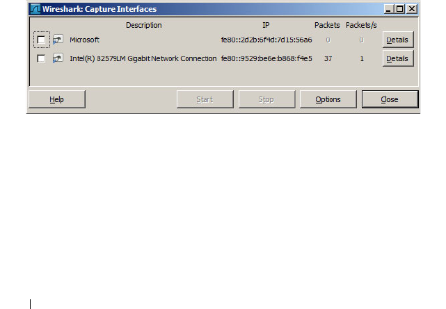
450 Monitoring Switch Traffic
Configuring Remote Capture
This example configures the switch to mirror packets transmitted and
received by the switch CPU to a Wireshark client. This is useful to diagnose
switch behavior and to determine if an attached device is sending properly
formatted packets with correct information to the switch, or just to monitor
traffic sent to the switch CPU. The capture feature can also be configured to
capture to a local file in pcap format or to capture to an in-memory buffer
(text format).
1
Configure capture for Wireshark remote access on port 2002.
console(config)#monitor capture remote
console(config)#exit
2
Start the capture enabling capture of both transmitted and received
packets.
console# monitor capture start all
3
Configure Wireshark for remote capture by selecting
Capture >
Interfaces
from the top tab. (The screens shown in this example are from
Wireshark 1.10.1.)
4
On the Capture Interfaces dialog, click
Options
.
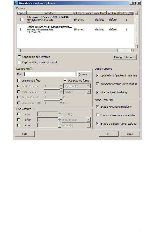
Monitoring Switch Traffic 451
5
On the Capture Options dialog, click
Manage Interfaces
.
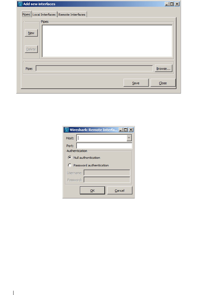
452 Monitoring Switch Traffic
6
Add a new interface by giving the switch IP address and the default remote
port (2002). First, select the
Remote Interfaces
tab and click
Add
.
7
Enter the switch IP address and port (2002). Choose
Null authentication
(default).
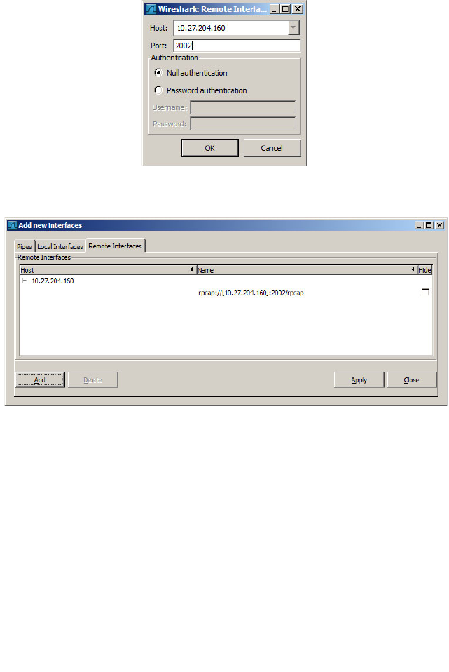
Monitoring Switch Traffic 453
8
Click
OK
to accept the entry.
9
On the Add new interfaces dialog, click
Apply
and then click
Close
.
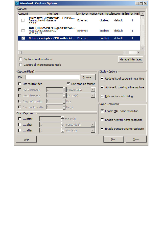
454 Monitoring Switch Traffic
10
From the Wireshark:Capture Options dialog, select the remote switch and
click
Start
.
Remote Capture Caveats
Remote capture over an in-band port captures the capture packets
transmitted to the Wireshark client. Therefore, when using remote capture
over an in-band port, it is best to configure remote capture to capture only
received packets, to configure remote capture to operate over the out-of-band
port, or to configure local capture to capture to the in-memory buffer or a
local pcap file.

Monitoring Switch Traffic 455
Configuring RSPAN
RSPAN supports the transport of mirrored packets across the network to a
remote switch. Ports may be configured as source ports, intermediate ports, or
destination ports.
RSPAN Source Switch
This example mirrors interface gi1/0/3 to VLAN 723. VLAN 723 is the
selected transit VLAN. Administrators should reserve a VLAN as the RSPAN
VLAN when designing their network. The source switch requires a reflector
port to carry packets to the transit switch. The reflector port must be
configured as trunk port. Untagged packets on the source port are transmitted
on the RSPAN VLAN tagged with the RSPAN VLAN. Tagged packets on the
source port are transmitted over the RPSAN VLAN double-tagged with the
outer tag containing the RSPAN VLAN.
The last line in this configuration enables the monitor session. It is
recommended that configuration proceed with the destination switch first,
followed by the intermediate switches, and then by the source switch.
1
Configure RSPAN on VLAN 723:
console#configure
console(config)#vlan 723
console(config-vlan723)#remote-span
console(config-vlan723)#exit
2
Configure interface te1/0/1 as the reflector port in trunk mode:
console(config)#interface te1/0/1
console(config-if-Te1/0/1)#switchport mode trunk
console(config-if-Te1/0/1)#switchport trunk
allowed vlan 723
console(config-if-Te1/0/1)#exit
3
Configure a mirroring session with a source port gi1/0/3, the destination
VLAN 723, and reflector port te1/0/1:
console(config)# monitor session 1 source
interface gi1/0/3
console(config)# monitor session 1 destination
remote vlan 723 reflector-port te1/0/1

456 Monitoring Switch Traffic
4
Enable the monitor session:
console(config)#monitor session 1 mode
RSPAN cannot use the CPU as a mirror source. Instead, configure remote
capture to view packets sent to or from the switch CPU.
RSPAN Transit Switch
The following is an example of an RSPAN transit switch configuration. The
RSPAN VLAN should be configured as a remote-span in order to disable
MAC learning on the VLAN. In this case, the transit switch ports are
configured as trunk ports (members of all VLANs) and may be used by other
traffic. Packets on the transit switch (in this example) are received and
transmitted tagged.
1
Configure remote span on a VLAN:
console#configure
console(config)#vlan 723
console(config-vlan723)#remote-span
console(config-vlan723)#exit
2
Configure the transit switch ports in trunk mode:
console(config)#interface te1/0/1
console(config-if-Te1/0/1)#switchport mode trunk
console(config-if-Te1/0/1)#interface te1/0/2
console(config-if-Te1/0/2)#switchport mode trunk
RSPAN Destination Switch
The following example shows the configuration of the RSPAN destination
switch. The RSPAN mirrored packets are transmitted over the destination
port untagged.
1
Configure remote span on VLAN 723:
console#configure
console(config)#vlan 723
console(config-vlan723)#remote-span
console(config-vlan723)#exit
2
Configure interface te1/0/1 as the destination port.
console(config)#interface te1/0/1

Monitoring Switch Traffic 457
console(config-if-Te1/0/1)#switchport mode trunk
console(config-if-Te1/0/1)#switchport trunk
allowed vlan 723
console(config-if-Te1/0/1)#exit
3
Configure a mirroring session with the remote VLAN 723 as the source
and inteface gi1/0/1 as the destination port:
console(config)#monitor session 1 source remote
vlan 723
console(config)#monitor session 1 destination
interface gi1/0/1
4
Enable the mirroring session:
console(config)#monitor session 1 mode

458 Monitoring Switch Traffic

Configuring iSCSI Optimization 459
17
Configuring iSCSI Optimization
NOTE: This feature is not available on N2000 switches.
This chapter describes how to configure Internet Small Computer System
Interface (iSCSI) optimization, which enables special quality of service
(QoS) treatment for iSCSI traffic.
The topics covered in this chapter include:
• iSCSI Optimization Overview
• Default iSCSI Optimization Values
• Configuring iSCSI Optimization (Web)
• Configuring iSCSI Optimization (CLI)
• iSCSI Optimization Configuration Examples
iSCSI Optimization Overview
iSCSI optimization provides a means of monitoring iSCSI sessions and iSCSI
traffic on the switch. This is accomplished by monitoring, or “snooping,”
traffic to detect packets used by iSCSI stations to establish iSCSI sessions
and connections. Data from these exchanges may optionally be used to create
classification rules to assign traffic between the stations to a configured traffic
class. The traffic classification affects how the packets in the flow are queued
and scheduled for egress on the destination port.

460 Configuring iSCSI Optimization
What Does iSCSI Optimization Do?
In networks containing iSCSI initiators and targets, iSCSI Optimization
helps to monitor iSCSI sessions or give iSCSI traffic preferential QoS
treatment. Dynamically-generated classifier rules generated by snooping
iSCSI traffic are used to direct iSCSI data traffic to queues that can be given
the desired preference characteristics over other data traveling through the
switch. This may help to avoid session interruptions during times of
congestion that would otherwise cause iSCSI packets to be dropped.
However, in systems where a large proportion of traffic is iSCSI, it may also
interfere with other network control-plane traffic, such as ARP or LACP.
The preferential treatment of iSCSI traffic needs to be balanced against the
needs of other critical data in the network.
How Does the Switch Detect iSCSI Traffic Flows?
The switch snoops iSCSI session establishment (target login) and
termination (target logout) packets by installing classifier rules that trap
iSCSI protocol packets to the CPU for examination. Devices that initiate
iSCSI sessions generally use well-known TCP ports 3260 or 860 to contact
targets. When iSCSI optimization is enabled, by default the switch identifies
IP packets to or from these ports as iSCSI session traffic. In addition, the
switch separately tracks connections associated with a login session (ISID)
(dynamically allocated source/destination TCP port numbers). You can
configure the switch to monitor traffic for additional port numbers or port
number-target IP address combinations, and you can remove the well-known
port numbers from monitoring. You can also associate a target name with a
configured target TCP port entry.
How Is Quality of Service Applied to iSCSI Traffic Flows?
The iSCSI CoS mode is configurable and controls whether CoS queue
assignment and/or packet marking is performed on iSCSI traffic. When the
iSCSI CoS mode is enabled, the CoS policy is applied to packets in detected
iSCSI sessions. In addition, if DCBX is enabled (on N4000 switches only), the
iSCSI application priority TLV is generated by the switch. When the iSCSI
CoS mode is disabled, iSCSI sessions and connections are detected and
shown in the status tables, but no CoS policy is applied to packets.

Configuring iSCSI Optimization 461
On N4000 switches, when the iSCSI CoS mode is disabled, the DCBX iSCSI
Application Priority TLV is not generated by the switch. In either case, if
DCBX is enabled and ports are configured as auto-up or auto-down, the
Application Priority TLVs received from the configuration source are proxied
to the other ports and, on the N4000 series switches, the CoS policy for iSCSI
received via DCBX is applied to iSCSI packets.
When iSCSI CoS mode is enabled, iSCSI login sessions up to the switch
limits are tracked, and data packets for those sessions are given the configured
CoS treatment. iSCSI sessions in excess of the switch limits are not given the
configured CoS treament; therefore, it is not advisable to exceed the iSCSI
session limit. Multiple connections within a session are counted against the
session limit, even though they show in the session table as a single session.
In the switch, iSCSI connections are aged out using the session aging timer. If
the connection has no detected data packets during the timeout period, the
connection is deleted from the switch internal session table. When all
connections associated with a session age out or disconnect, the session is
deleted.
You can configure whether the iSCSI optimization feature uses the VLAN
priority or IP DSCP mapping to determine the traffic class queue. By default,
iSCSI flows are assigned to the highest VLAN priority tag or DSCP value
mapped to the highest queue not used for stack management or voice VLAN.
Use the classofservice dot1p-mapping command or the Quality of Service →
Class of Service → Mapping Table Configuration page to configure the
relevant Class of Service parameters for the queue in order to complete the
setting.
You can configure whether iSCSI frames are remarked to contain the
configured VLAN priority tag or IP DSCP when forwarded through the
switch.
How Does iSCSI Optimization Use ACLs?
iSCSI Optimization borrows ACL lists from the global system pool. ACL lists
allocated by iSCSI Optimization reduce the total number of ACLs available
for use by the network operator. Enabling iSCSI Optimization uses one ACL
list to monitor for iSCSI sessions. Each monitored iSCSI session utilizes two
rules from additional ACL lists up to a maximum of two ACL lists. This
means that the maximum number of ACL lists allocated by iSCSI is three.

462 Configuring iSCSI Optimization
What Information Does the Switch Track in iSCSI Traffic Flows?
Packets are examined to find the following data, which is used in tracking the
session and creating the classifier entries that enable QoS treatment:
• Initiator's IP Address
• Target's IP Address
• ISID (Initiator defined session identifier)
• Initiator's IQN (iSCSI Qualified Name)
•Target's IQN
•Initiator's TCP Port
•Target's TCP Port
If no iSCSI traffic is detected for a session for a configurable aging period, the
session data is cleared.

Configuring iSCSI Optimization 463
How Does iSCSI Optimization Interact With Dell EqualLogic Arrays?
The iSCSI feature includes auto-provisioning support with the ability to
detect directly connected Dell EqualLogic (EQL) SAN storage arrays and
automatically reconfigure the switch to enhance storage traffic flows.
The Dell Networking series switches use LLDP, a vendor-neutral protocol, to
discover Dell EQL devices on the network. LLDP is enabled by default. For
more information about LLDP, see "Discovering Network Devices" on
page 761.
When the switch detects a Dell EQL array, the following actions occur:
• An MTU of 9216 is enabled on the system, if it is not already enabled.
• Spanning tree portfast is enabled on the EQL-connected interface
identified by LLDP.
• Unicast storm control is disabled on the EQL-connected interface
identified by LLDP.
It is advisable to enable spanning tree portfast and disable unicast storm
control on ports connected to the initiators as well.
If the iSCSI CoS policy feature is enabled on the switch and an EQL array is
detected, the switch applies additional iSCSI CoS policies to the EQL inter-
array traffic on TCP ports 9876 and 25555. If the iSCSI CoS policy is disabled
and EQL arrays are present, the additional CoS policy is removed globally.
What Occurs When iSCSI Optimization Is Enabled or Disabled?
When iSCSI is enabled on the switch, the following actions occur:
• Flow control is globally enabled, if it is not already enabled.
• iSCSI session snooping is enabled
• iSCSI LLDP monitoring starts to automatically detect Dell EqualLogic
arrays.
If the iSCSI feature is disabled on the switch, iSCSI resources are released
and the detection of Dell EqualLogic arrays by using LLDP is disabled.
Disabling iSCSI does not remove the MTU, flow control, portfast or storm
control configuration applied as a result of enabling iSCSI. iSCSI
Optimization is enabled by default.

464 Configuring iSCSI Optimization
How Does iSCSI Optimization Interact with DCBx?
The Data Center Bridging Exchange (DCBx) component supports the
reception, decoding, and transmission of the Application Priority TLV. In
general, if the Application Priority TLV has been received from the
configuration source, it will be transmitted to the other auto configuration
ports. The DCBx component contains a control to generate the Application
Priority TLV for iSCSI if it is not already present in the DCBX information.
DCBx generates an Application Priority TLV whenever the following
conditions are met:
•An
EqualLogic
array has been detected on the port
• iSCSI CoS is enabled using a VPT value
The generated Application Priority TLV will contain the following values (in
addition to any other information contained in the TLV):
•AE Selector=14
• AE Protocol=3260
• AE Priority=priority configured for iSCSI PFC by the
iscsi cos vpt
command (default priority is 4)
The existing application priority entries being transmitted, if any, will not be
disturbed.
How Does iSCSI Optimization Interact with Dell Compellent Arrays?
Dell Networking switches support a macro that may be used to configure a
port connected to a Dell Compellent storage array. The name of the macro is
profile-compellent-nas. The macro takes a single argument: the
interface identifier to which the Dell Compellent array is connected. The
macro disables unicast storm control and sets the spanning tree configuration
on the port to portfast. For an example of how to execute the macro, see
NOTE: The DCBx feature is available on the N4000 switches only.
NOTE: If it is desired to utilize DCBX to configure lossless transport of iSCSI using
PFC, the operator MUST configure a non-default VLAN end-to-end in order to
transport the VLAN priority tag and ensure proper COS treatment on every network
enabled device, including CNAs and the EQL arrays.

Configuring iSCSI Optimization 465
"Configuring iSCSI Optimization Between Servers and a Disk Array" on
page 473.
iSCSI CoS and Priority Flow Control/Enhanced Transmission Selection
Interactions
When manually or automatically enabling the classification of iSCSI flows on
N4000 series switches, enabling iSCSI CoS is not recommended unless
required as follows.
When using manual configuration of the switch or auto-configuration via
DCBX, the iSCSI packets are classified based on the user priority present in
the VLAN tag and, in this case, enabling iSCSI CoS classification via the
iSCSI command set provides no benefit. The only case for enabling iSCSI
CoS prioritization is when using N4000 series switches to originate iSCSI
configuration information via DCBX. In this case, enabling iSCSI CoS
classification configures the N4000 switch to generate the iSCSI TLV via
DCBX in support of configuring directly connected storage and initiator
devices. N4000 series switches support both ETS and DCBx and support
DCB configuration in conjunction with EQL devices.
NOTE: The ETS feature is available on the N4000 switches only.

466 Configuring iSCSI Optimization
Default iSCSI Optimization Values
Table 17-1 shows the default values for the iSCSI optimization feature.
Table 17-1. iSCSI Optimization Defaults
Parameter Default Value
iSCSI optimization global status Enabled
iSCSI CoS mode Disabled
Jumbo frames Disabled
Spanning tree portfast Disabled
Unicast storm control Disabled
Classification iSCSI packets are classified by VLAN
instead of by DSCP values.
VLAN priority tag iSCSI flows are assigned by default the
highest 802.1p VLAN priority tag mapped
to the highest queue not used for stack
management or the voice VLAN.
DSCP When DSCP is selected as the
classification, iSCSI flows are assigned by
default the highest DSCP tag mapped to
the highest queue not used for stack
management or the voice VLAN.
Remark Not enabled
iSCSI session aging time 10 minutes
iSCSI optimization target ports iSCSI well-known ports 3260 and 860 are
configured as default (with no IP address or
name) but can be removed as any other
configured target.
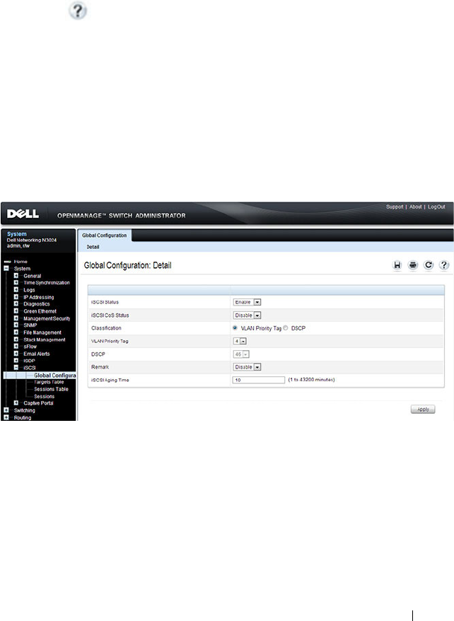
Configuring iSCSI Optimization 467
Configuring iSCSI Optimization (Web)
This section provides information about the OpenManage Switch
Administrator pages to use to the iSCSI features on a Dell Networking
N2000, N3000, and N4000 series switches. For details about the fields on a
page, click at the top of the page.
iSCSI Global Configuration
Use the Global Configuration page to allow the switch to snoop for iSCSI
sessions/connections and to configure QoS treatment for packets where the
iSCSI protocol is detected.
To access the iSCSI Global Configuration page, click System → iSCSI →
Global Configuration in the navigation panel.
Figure 17-1. iSCSI Global Configuration
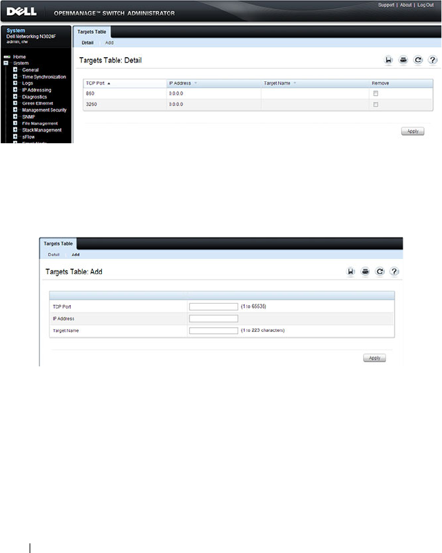
468 Configuring iSCSI Optimization
iSCSI Targets Table
Use the Targets Table page to view and configure iSCSI targets on the switch.
To access the Targ ets Table page, click System → iSCSI → Targets in the
navigation panel.
Figure 17-2. iSCSI Targets Table
To add an iSCSI Target, click Add at the top of the page and configure the
relevant information about the iSCSI target.
Figure 17-3. Add iSCSI Targets
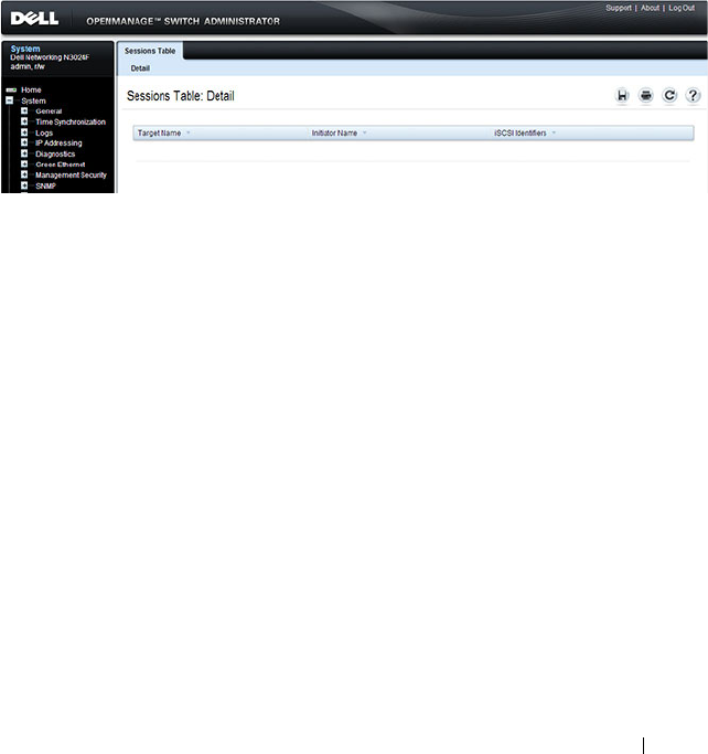
Configuring iSCSI Optimization 469
iSCSI Sessions Table
Use the Sessions Table page to view summary information about the iSCSI
sessions that the switch has discovered. An iSCSI session occurs when an
iSCSI initiator and iSCSI target communicate over one or more TCP
connections. The maximum number of iSCSI sessions is 192. Redundant
(MPIO paths) may not be accounted for in the iSCSI sessions table if a
separate iSCSI login is not issued during establishment of the session.
To access the Sessions Table page, click System → iSCSI → Sessions Table in
the navigation panel.
Figure 17-4. iSCSI Sessions Table
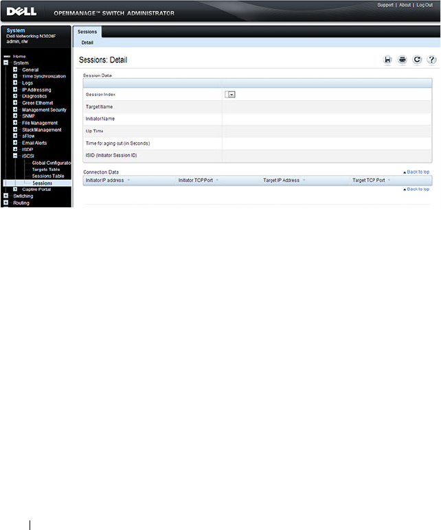
470 Configuring iSCSI Optimization
iSCSI Sessions Detailed
Use the Sessions Detailed page to view detailed information about an iSCSI
sessions that the switch has discovered.
To access the Sessions Detailed page, click System → iSCSI → Sessions
Detailed in the navigation panel.
Figure 17-5. iSCSI Sessions Detail

Configuring iSCSI Optimization 471
Configuring iSCSI Optimization (CLI)
This section provides information about the commands you use to configure
iSCSI settings on the switch. For more information about the commands, see
the
Dell Networking N2000, N3000, and N4000 Series Switches CLI
Reference Guide
at support.dell.com/manuals.
Command Purpose
configure Enter Global Configuration mode. iSCSI
optimization is enabled by default.
iscsi target port
tcp-port-1
[
tcp-port-2...tcp-port-16
]
[address
ip-address
] [name
targetname
]
Configure an iSCSI target port and, optionally,
address and name.
•
tcp-port-n
—TCP port number or list of TCP port
numbers on which the iSCSI target listens to
requests. Up to 16 TCP ports can be defined in the
system in one command or by using multiple
commands.
•
ip-address
—IP address of the iSCSI target. When
the no form of this command is used, and the tcp
port to be deleted is one bound to a specific IP
address, the address field must be present.
•
targetname
—iSCSI name of the iSCSI target. The
name can be statically configured; however, it can be
obtained from iSNS or from sendTargets response.
The initiator must present both its iSCSI Initiator
Name and the iSCSI Target Name to which it wishes
to connect in the first login request of a new session
or connection.

472 Configuring iSCSI Optimization
iscsi cos {enable | disable |
vtp
vtp
| dscp
dscp
[remark]
Optionally set the quality of service profile that will
be applied to iSCSI flows.
•
enable
—Enables application of preferential QoS
treatment to iSCSI frames. On switches that
support DCBX, this also enables the generation of
the Application Priority TLV for iSCSI.
•
disable
—Disables application of preferential QoS
treatment to iSCSI frames.
•
vpt
/
dscp
—The VLAN Priority Tag or DSCP value to
assign received iSCSI session packets.
•
remark
—Mark the iSCSI frames with the configured
DSCP value when egressing the switch.
iscsi aging time
time
Optionally set aging time (range: 1–43,200 seconds)
for iSCSI connections. When all connections
associated with a session are aged out, the session is
deleted.
exit Exit to Privilege Exec mode.
show iscsi Display iSCSI settings.
show iscsi sessions Display iSCSI session information. Redundant
(MPIO paths) may not be accounted for in the iSCSI
sessions table if a separate iSCSI login is not issued
during establishment of the session.
Command Purpose
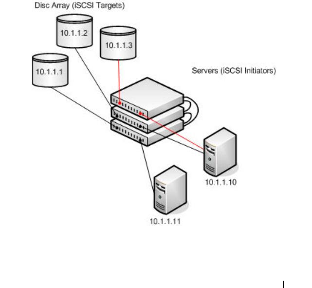
Configuring iSCSI Optimization 473
iSCSI Optimization Configuration Examples
iSCSI optimization is enabled by default with the appropriate settings to
operate properly is almost all configurations. However, you find it necessary to
alter those settings, the following procedure illustrates the configuration steps
required.
Configuring iSCSI Optimization Between Servers and a Disk Array
Figure 17-6 illustrates a stack of three Dell Networking series switches
connecting two servers (iSCSI initiators) to a disk array (iSCSI targets).
An iSCSI application running on the management unit (the top unit in the
diagram) has installed priority filters to ensure that iSCSI traffic that is part
of these two sessions receives priority treatment when forwarded in hardware.
Figure 17-6. iSCSI Optimization

474 Configuring iSCSI Optimization
The following commands show how to configure the iSCSI example depicted
in Figure 17-6. Remember that iSCSI optimization is enabled by default.
1
Set the system MTU to 9216 to enable the use of jumbo frames.
console#config
console(config)#system jumbo mtu 9216
2
Optionally configure the switch to associate CoS queue 5 with detected
iSCSI session traffic.
console(config)#iscsi cos enable
console(config)#exit
The default target port and IP address criteria is used to determine which
packets are snooped for iSCSI session data (ports 860 and 3260; any IP
address).
3
If the array is a Compellent storage array, execute the Compellent macro
on the ports attached to the array:
console#config
console(config)#macro global apply profile-compellent-nas
$interface_name te1/0/21
console(config)#macro global apply profile-compellent-nas
$interface_name te1/0/22
console(config)#macro global apply profile-compellent-nas
$interface_name te1/0/23
To configure a N4000 switch in a lossless DCBX environment where another
switch connected to storage arrays supplies the DCBX configuration, perform
the following steps starting with a default configuration:
1
Enter global configuration mode and configure the system MTU on the
switch.
console#configure
console(config)#system jumbo mtu 9216
2
Create VLAN 100. This command also enters the VLAN configuration
mode for VLAN 100.
console(config)#vlan 100
console(config-vlan100)#exit
3
Enable VLAN tagging to allow the CNA ports 1-4 to carry 802.1p priority
values through the network.
console(config)#interface range te1/0/1-4

Configuring iSCSI Optimization 475
console(config-if)#switchport mode trunk
4
Configure the DCBx port role as auto-downstream. This step
automatically enables PFC and ETS on the ports using the configuration
received from the other switch.
console(config-if)#lldp dcbx port-role auto-down
console(config-if)#exit
5
Enter interface configuration mode for the switch-facing ports and
configure the DCBx port role as auto-up. This step automatically enables
PFC and ETS on the ports using the configuration received from the other
switch.
console(config)#interface range te1/0/16-17
console(config-if)#lldp dcbx port-role auto-up
6
Add the ports to port-channel 1:
console(config-if)#channel-group 1 mode active
console(config-if)#exit
7
Configure the port-channel to be in trunk mode:
console(config)#interface po1
console(config-if)#switchport mode trunk
console(config-if)#exit
To configure a N4000 switch in a lossless DCBX environment where the
switch is directly connected to storage arrays and the CNAs (no other switch
is present), perform the following steps starting from a default configuration:
1
Enter global configuration mode and configure the system MTU on the
switch.
console#configure
console(config)#system jumbo mtu 9216
2
Create VLAN 100. This command also enters the VLAN configuration
mode for VLAN 100.
console(config)#vlan 100
console(config-vlan100)#exit
3
Enable iSCSI CoS. This enables generation of the iSCSI Application
Priority TLV required by the CNAs.
console(config)#iscsi cos enable
4
Map VLAN priority 4 onto traffic class 4.
(config)#classofservice dot1p-mapping 4 4

476 Configuring iSCSI Optimization
5
Enter Interface Configuration mode for CNA connected ports 1-4 and
array connected ports 16-17.
console(config)#interface range te1/0/1-4,te1/0/16-17
6
Enable VLAN tagging to allow the CNA connected ports to carry 802.1p
priority values through the network.
console(config-if)#switchport mode trunk
7
Enter datacenter bridging mode to enable PFC on the ports.
console(config-if)#datacenter-bridging
8
Enable PFC and configure traffic marked with 802.1p priority 4 to be
paused rather than dropped when congestion occurs.
console(config-if-dcb)#priority-flow-control mode on
console(config-if-dcb)#priority-flow-control priority 4
no-drop
console(config-if-dcb)#exit
9
Configure ETS by mapping the lossless traffic onto TC 1 and sharing
bandwidth equally between the lossless and lossy traffic classes.
console(config-if)#classofservice traffic-class-group 0 0
console(config-if)#classofservice traffic-class-group 1 0
console(config-if)#classofservice traffic-class-group 2 0
console(config-if)#classofservice traffic-class-group 3 0
console(config-if)#classofservice traffic-class-group 4 1
console(config-if)#classofservice weight 50 50 0
10
Exit interface configuration mode for the range of interfaces.
console(config-if)#exit

Configuring Port Characteristics 477
18
Configuring Port Characteristics
This chapter describes how to configure physical switch port characteristics,
including settings such as administrative status and maximum frame
sizeGreen Ethernet settings. This chapter also describes the link dependency
feature.
The topics covered in this chapter include:
•Port Overview
• Default Port Values
• Configuring Port Characteristics (Web)
• Configuring Port Characteristics (CLI)
• Port Configuration Examples
Port Overview
A port is a physical interface. Cables physically connect ports on devices such
as PCs or servers to ports on the switch to provide access to the network. The
number and type of physical ports available on your Dell Networking N2000,
N3000, and N4000 series switches depends on the model.
What Physical Port Characteristics Can Be Configured?
Table 18-1Table 18-2 provides a summary of the physical characteristics that
can be configured on the switch ports.
Table 18-1. Port Characteristics
Feature Description
Administrative status Controls whether the port is administratively
enabled or disabled.
Description Provides a text-based description of the port.

478 Configuring Port Characteristics
Auto negotiation Enables a port to advertise its transmission rate,
duplex mode and flow control abilities to its
partner.
Speed Specifies the transmission rate for frames.
Duplex mode Specifies whether the interface supports
transmission between the switch and the
connected client in one direction at a time (half)
or both directions simultaneously (both).
Maximum frame size Indicates the maximum frame size that can be
handled by the port.
Green Ethernet features Green Ethernet features include:
• Energy detect mode
•
Energy Efficient Ethernet (EEE), which
enables the l
ow-power idle mode
Flow control This is a global setting that affects all ports. For
more information about this feature, see
"Configuring Port-Based Traffic Control" on
page 787.
Storm control For more information about this feature, see
"Configuring Port-Based Traffic Control" on
page 787.
Port security For more information about this feature, see
"Configuring Port and System Security" on
page 503.
Protected port For more information about this feature, see
"Configuring Port-Based Traffic Control" on
page 787.
Table 18-2. Port Characteristics
Feature Description
Administrative status Controls whether the port is administratively
enabled or disabled.
Description Provides a text-based description of the port.
Table 18-1. Port Characteristics
Feature Description

Configuring Port Characteristics 479
What is Link Dependency?
The link dependency feature provides the ability to enable or disable one or
more ports based on the link state of one or more different ports. With link
dependency enabled on a port, the link state of that port is dependent on the
link state of another port. For example, if port A is dependent on port B and
the switch detects a link loss on port B, the switch automatically brings down
the link on port A. When the link is restored to port B, the switch
automatically restores the link to port A.
Auto negotiation Enables a port to advertise its transmission rate,
duplex mode and flow control abilities to its
partner.
Speed Specifies the transmission rate for frames.
Duplex mode Specifies whether the interface supports
transmission between the switch and the
connected client in one direction at a time (half)
or both directions simultaneously (both).
Maximum frame size Indicates the maximum frame size that can be
handled by the port.
Flow control This is a global setting that affects all ports. For
more information about this feature, see
"Configuring Port-Based Traffic Control" on
page 787.
Storm control For more information about this feature, see
"Configuring Port-Based Traffic Control" on
page 787.
Port security For more information about this feature, see
"Configuring Port and System Security" on
page 503.
Protected port For more information about this feature, see
"Configuring Port-Based Traffic Control" on
page 787.
Table 18-2. Port Characteristics (Continued)
Feature Description

480 Configuring Port Characteristics
You can create a maximum of 72 dependency groups16 groups. The ports
participating in the Link Dependency can be across all the Stack Units
(Manager/Member unit).
Link Action
The link action specifies the action that the group members will take when
the dependent port is down. The group members can transition to the same
state as the dependant port, or they can transition to the opposite state. In
other words, if the link action is down and the dependent port goes down, the
members ports will go down as well. Conversely, when the link action is up
and the dependant link goes down, the group member ports are enabled
(brought up).
Creating a link dependency group with the up link action essentially creates a
backup link for the dependent link and alleviates the need to implement STP
to handle the fail-over.
Link Dependency Scenarios
The Link Dependency feature supports the scenarios in the following list.
• Port dependent on port — If a port loses the link, the switch brings
up/down the link on another port.
• Port dependent on LAG — If all ports in a channel-group lose the link, the
switch brings up/down the link on another port.
• LAG dependent on port — If a port loses the link, the switch brings
up/down all links in a channel-group.
• Multiple port command — If a group of ports lose their link, the switch
brings up/down the link on another group of ports.
• Overlapping ports — Overlapping ports on different groups will be
brought up/down only if both dependent ports lose the link.
NOTE: Whether the member ports or LAGs are brought
up
or
down
depends on
the link action.

Configuring Port Characteristics 481
What Interface Types are Supported?
The physical ports on the switch include the out-of-band (OOB) interface
(N3000 and N4000 only) and Ethernet switch ports. The OOB interface
supports a limited set of features and is for switch management only. The
Ethernet switch ports support many logical features that are often supported
by logical interfaces. The switch supports the following types of logical
interfaces:
• Port-based VLANs — For more information, see
"Configuring VLANs
" on
page 645
.
• VLAN routing interfaces — For more information, see
"Configuring
Routing Interfaces
" on page 1021
.
• Link Aggregation Groups (LAGs), which are also called port-channels) —
For more information, see
"Configuring Link Aggregation
" on page 913
.
• Tunnels — For more information, see
"Configuring Routing Interfaces
"
on page 1021
.
• Loopback interfaces — For more information, see
"Configuring Routing
Interfaces
" on page 1021
.
The Dell Networking switches includes the following Power over Ethernet
(PoE) Plus models: the N2024P, N2048P, N3024P, N3048P. For information
about configuring PoE plus features for the ports, see "Managing General
System Settings" on page 279.
N3000 and N4000 switches have a single expansion slot and can support the
following module types:
•10GBaseT module
•SFP+ module
•QSFP+ module (
N4000
only)
What is Interface Configuration Mode?
When you use the CLI to configure physical or logical characteristics for an
interface, you must enter Interface Configuration Mode for that interface. To
enter the mode, type the keyword interface followed by the interface type and
additional information to identify the interface, such as the interface number.

482 Configuring Port Characteristics
To enter Interface Configuration mode for a physical switch port, the
following information is required:
• Type — For physical switch ports, the type is Gigabit Ethernet
(gigabitethernet or gi) for 10/100/1000 Mbps Ethernet ports or 10-Gibabit
Ethernet (tengigabitethernet or te) for 10,000 Mbps Ethernet ports.
• Stack member number— The unit number within the stack. The range is
1–12. The default unit number for a switch that has not been in a stack is
1. To view the member number assigned to each switch in a stack, use the
show switch
command.
• Module (slot) number—For the N4000, the slot number is always 0.The
expansion module slot. The number is 1 for a module inserted in the left
slot or 2 when it is in the right slot (when viewing the back panel of the
switch). For front-panel ports, the slot number is 0.
• Port number—The number assigned to the port. For front-panel ports the
port number is written above or below each port. Odd-numbered ports are
on the top row, and even-numbered ports are on the bottom row. The port
numbers increase from left to right. For ports on the optional modules, the
left port is 1, and the right port is 2.
For example, to enter Interface Configuration mode for Gigabit Ethernet
port 10 on a switch that is not part of a stack, use the following command:
console(config)#interface gigabitEthernet 1/0/10
For example, to enter Interface Configuration mode for 10-Gigabit Ethernet
port 10, use the following command:
console(config)#interface tengigabitEthernet 1/0/10
To enter Interface Configuration mode for Gigabit Ethernet port 6 on stack
member 3, use the following command:
console(config)#interface gigabitEthernet 3/0/6
To enter Interface Configuration mode for port 1 on a 10-Gigabit Ethernet
module in the left slot, use the following command:
console(config)#interface tengigabitEthernet 1/1/1
NOTE: When you enter Interface Configuration mode, the command prompt
changes and identifies the interface. In the previous example, the command
prompt becomes console(config-if-Te1/0/10)#.

Configuring Port Characteristics 483
For many features, you can configure a range of interfaces. When you enter
Interface Configuration mode for multiple interfaces, the commands you
execute apply to all interfaces specified in the range.
To enter Interface Configuration mode for a range of interfaces, include the
keyword range and specify the interfaces to configure. For example, to apply
the same configuration to ports 1-10 on a standalone switch, use the
following command:
console(config)#interface range tengigabitEthernet
1/0/1-10
To enter Interface Configuration mode for ports 3, 4, 5, 12, and 14 on a
standalone switch, use the following command:
console(config)#interface range tengigabitEthernet
1/0/3-5,1/0/12,1/0/14
What Are the Green Ethernet Features?
The Green Ethernet feature supports two per-port power-saving modes:
• Energy-detect Mode
•EEE
All integrated 1G and module-based 10G copper ports on Dell Networking
series switches are capable of utilizing the Energy Detect and EEE modes for
reduced power consumption.
When the Energy Detect mode is enabled and the port link is down, the PHY
automatically goes down for short period of time and then wakes up to check
link pulses. This mode reduces power consumption on the port when no link
partner is present.
EEE enables ports to enter a low-power mode to reduce power consumption
during periods of low link utilization. EEE is defined by IEEE 802.3az. EEE
enables both the send and receive sides of the link to disable some
functionality for power savings when the link is lightly loaded.
NOTE: You can switch to another interface or range of interfaces by entering the
interface command while in Interface Configuration mode. It is not necessary to
exit Interface Configuration mode to select a different interface.

484 Configuring Port Characteristics
NOTE: Cable diagnostics may give misleading results if green mode is enabled
on the port. Disable green mode prior to running any cable diagnostics.
Configuring Port Characteristics 485
Default Port Values
Table 18-3Table 18-4 lists the default values for the port characteristics that
this chapter describes.
Table 18-3. Default Port Values
Feature Description
Administrative status All ports are enabled
Description None defined
Auto negotiation Enabled
Speed Auto-negotiate
Duplex mode Auto-negotiate
Flow control Enabled
Maximum frame size 1518
Energy Detect mode Disabled
EEE mode Disabled
Link Dependency None configured
Table 18-4. Default Port Values
Feature Description
Administrative status All ports are enabled
Description None defined
Auto negotiation Enabled
Speed Auto negotiate
Duplex mode Auto negotiate
Flow control Enabled
Maximum frame size 1518
Link Dependency None configured
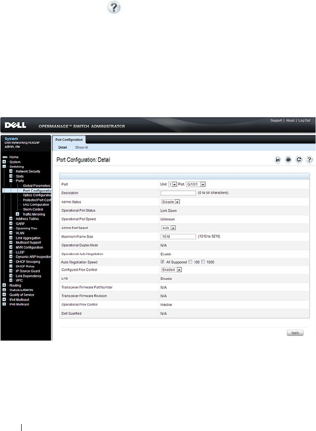
486 Configuring Port Characteristics
Configuring Port Characteristics (Web)
This section provides information about the OpenManage Switch
Administrator pages for configuring and monitoring port characteristics on a
Dell Networking N2000, N3000, and N4000 series switches. For details about
the fields on a page, click at the top of the page.
Port Configuration
Use the Port Configuration page to define port parameters.
To display the Port Configuration page, click Switching
→
Ports
→
Port
Configuration in the navigation panel.
Figure 18-1. Port Configuration
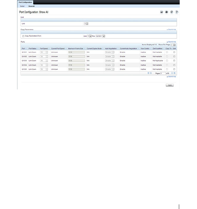
Configuring Port Characteristics 487
Configuring Multiple Ports
To configure port settings on multiple ports:
1
Open the
Port Configuration
page.
2
Click
Show All
to display the
Port Configuration Table
page.
3
In the
Ports
list, select the check box in the
Edit
column for the port to
configure.
4
Select the desired settings.
5
Click
Apply
.
Figure 18-2. Configure Port Settings
6
Select the
Copy Parameters From
check box, and select the port with the
settings to apply to other ports.
7
In the
Ports
list, select the check box(es) in the
Copy To
column that will
have the same settings as the port selected in the
Copy Parameters From
field.
In the following example, Ports 3, 4, and 5 will be updated with the
settings that are applied to Port 1.
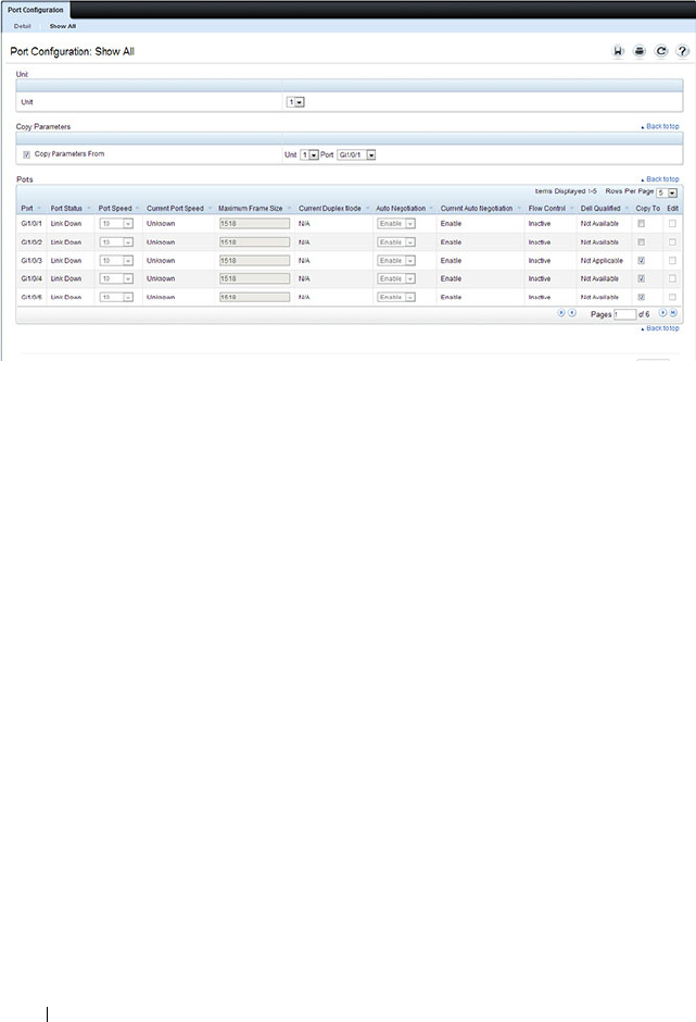
488 Configuring Port Characteristics
Figure 18-3. Copy Port Settings
8
Click
Apply
.
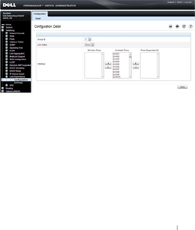
Configuring Port Characteristics 489
Link Dependency Configuration
Use the Link Dependency Configuration page to create link dependency
groups. You can create a maximum of 16 dependency groups. The page
displays the groups whether they have been configured or not.
To display the Link Dependency Configuration page, click Switching
→
Link Dependency
→
Configuration in the navigation panel.
Figure 18-4. Link Dependency Configuration
Creating a Link Dependency Group
To create link dependencies:
1
Open the
Link Dependency Configuration
page.
2
In the
Group ID
field, select the ID of the group to configure.
3
Specify the link action.
4
To add a port to the
Member Ports
column, click the port in the
Available
Ports
column, and then click the < button to the left of the
Available
Ports
column. Ctrl + click to select multiple ports.
5
To add a port to the
Ports Depended On
column, click the port in the
Available Ports
column, and then click the > button to the right of the
Available Port
s column.
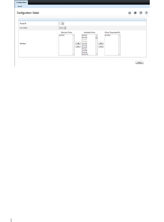
490 Configuring Port Characteristics
In the following example, Group 1 is configured so that Port 3 is
dependent on Port 4.
Figure 18-5. Link Dependency Group Configuration
6
Click
Apply
.
The Link Dependency settings for the group are modified, and the device
is updated.
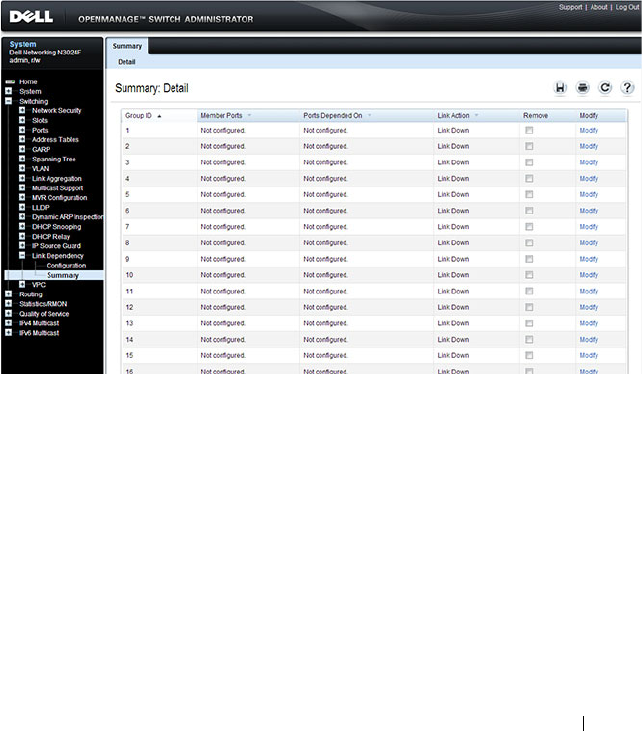
Configuring Port Characteristics 491
Link Dependency Summary
Use the Link Dependency Summary page to view all link dependencies on
the system and to access the Link Dependency Configuration page. You can
create a maximum of 16 dependency groups. The page displays the groups
whether they have been configured or not.
To display the Link Dependency Summary page, click Switching
→
Link
Dependency
→
Link Dependency Summary in the navigation panel.
Figure 18-6. Link Dependency Summary
To configure a group, click the Modify link associated with the ID of the
group to configure. Clicking the Modify link takes you to the Link
Dependency Configuration page. The Group ID is automatically selected
based on the link that was clicked.
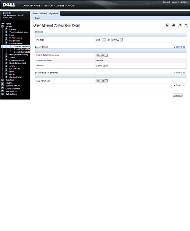
492 Configuring Port Characteristics
Port Green Ethernet Configuration
Use the Green Ethernet Configuration page to enable or disable energy-
saving modes on each port.
To display the Green Ethernet Configuration page, click System
→
Green
Ethernet
→
Green Ethernet Configuration in the navigation panel.
Figure 18-7. Green Ethernet Configuration
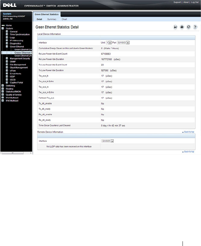
Configuring Port Characteristics 493
Port Green Ethernet Statistics
Use the Green Ethernet Statistics page to view information about per-port
energy savings.
To display the Green Ethernet Statistics page, click System
→
Green
Ethernet
→
Green Ethernet Statistics in the navigation panel.
Figure 18-8. Green Ethernet Statistics
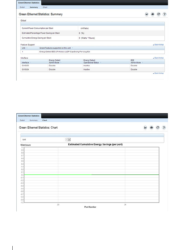
494 Configuring Port Characteristics
To view a summary of energy savings for the switch and all ports, click
Summary.
Figure 18-9. Green Ethernet Statistics Summary
To view a chart that shows the estimated per-port energy savings, click Chart.
Figure 18-10. Green Ethernet Statistics Chart
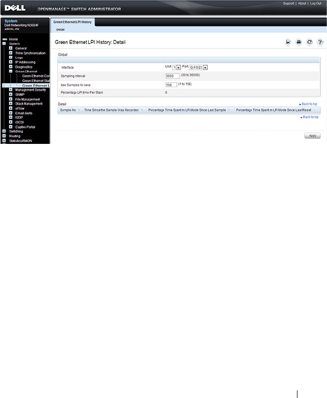
Configuring Port Characteristics 495
Port Green Ethernet LPI History
Use the Green Ethernet LPI History page to view data about the amount of
time the switch has spent in low-power idle (LPI) mode.
To display the Green Ethernet LPI History page, click System
→
Green
Ethernet
→
Green Ethernet LPI History in the navigation panel.
Figure 18-11. Green Ethernet LPI History

496 Configuring Port Characteristics
Configuring Port Characteristics (CLI)
This section provides information about the commands you use to configure
port characteristics. For more information about the commands, see the
Dell
Networking N2000, N3000, and N4000 Series Switches CLI Reference Guide
at support.dell.com/manuals.
Configuring Port Settings
Beginning in Privileged EXEC mode, use the following commands to
configure various port settings.
Command Purpose
configure Enter Global Configuration mode.
interface
interface
Enter interface configuration mode for the specified
interface. The
interface
variable includes the interface type
and number, for example tengigabitethernet 1/0/3.
You can also specify a range of interfaces with the interface
range command, for example, interface range
tengigabitethernet 1/0/8-12 configures interfaces 8, 9, 10,
11, and 12.
description
string
Add a description to the port. The text string can be
from1-64 characters.
shutdown Administratively disable the interface.

Configuring Port Characteristics 497
Configuring Link Dependencies
Beginning in Privileged EXEC mode, use the following commands to
configure ports that are dependent on the state of other ports.
speed {10
|100|1000|10000 | auto
[100|1000|10000]}
Configure the speed of a given Ethernet interface or allow
the interface to automatically detect the speed.
If you use the 100, 1000, or 10000 keywords with the auto
keyword, the port auto-negotiates only at the specified
speeds. Setting the speed without the auto keyword forces
the speed to the selected value and disables auto-
negotiation. It is possible to configure a fiber port for a
speed not supported by the transceiver. In this case, the
port will not link up.
On combo ports, it is possible to configure auto
negotiation even if only the fiber interface is active. The
auto negotiation settings will be utilized when the copper
port is active. Auto negotiation settings are ignored for the
fiber ports, as fiber ports alway operate in full-duplex
fixed-speed mode.
system jumbo mtu
size
Enable jumbo frames on the switch by adjusting the
maximum size of a packet.
CTRL + Z Exit to Privileged EXEC mode.
show interfaces status Show summary information about all interfaces.
show interfaces
configuration
View a summary of the configuration for all ports.
show interfaces advertise View a summary of the speeds that are advertised on each
port.
show interfaces
description
View configured descriptions for all ports.
show interfaces detail
interface
View detailed information about the specified port.
Command Purpose
configure Enter Global Configuration mode.
Command Purpose

498 Configuring Port Characteristics
Configuring Green Features
Beginning in Privileged EXEC mode, use the following commands to
configure and monitor energy-saving features for the ports and the switch.
link-dependency group
group_id
Enter the link-dependency mode to configure a link-
dependency group.
add
interface
Add member ports to the group.
The
interface
variable includes the interface type and
number, for example tengigabitethernet 1/0/3. You can
also add port-channels (LAGs) as members by using the
keyword port-channel followed by an ID.
You can also specify a range of interfaces. For example,
interface tengigabitethernet 1/0/8-10,1/0/20 configures
interfaces 8, 9, 10 and 20.
depends-on
interface
Specify the port(s) upon which the member ports are
dependent. For information about the
interface
variable,
see the previous command description.
action {down|up} Specifies the action the member ports take when the
dependent link goes down.
•
down
—When the dependent link is down, the group
members are down (the members are up otherwise).
•
up
—When the dependent link goes down, the group
members are brought up (the members are down
otherwise)
CTRL + Z Exit to Privileged EXEC mode.
show link-dependency
[group
group_id
]
View link dependency settings for all groups or for the
specified group, along with the group state.
Command Purpose
configure Enter Global Configuration mode.
Command Purpose

Configuring Port Characteristics 499
interface
interface
Enter interface configuration mode for the specified
interface. The
interface
variable includes the interface type
and number, for example gigabitethernet 1/0/3.
You can also specify a range of interfaces with the interface
range command, for example, interface range
gigabitethernet 1/0/8-12 configures interfaces 8, 9, 10, 11,
and 12.
green-mode energy-
detect
Enable energy-detect mode on the interface.
green-mode eee Enable EEE low power idle mode on the interface.
exit Exit to global configuration mode.
green-mode eee-lpi-
history {sampling-
interval
seconds
| max-
samples
max
}
Configure the global EEE LPI history collection interval
and buffer size.
exit Exit to Privileged EXEC mode.
show green-mode
interface
View green mode settings for the specified port.
show green-mode eee-
lpi-history interface
interface
View the EEE LPI history statistics for the specified port.
Command Purpose

500 Configuring Port Characteristics
Port Configuration Examples
This section contains the following examples:
• Configuring Port Settings
• Configuring a Link Dependency Groups
Configuring Port Settings
The commands in this example specify the speed and duplex mode for port 1
(gigabitEthernet 1/0/1) and change the system MTU size.
To configure the switch:
1
Enter Interface Configuration mode for port 1.
console#configure
console(config)#interface gigabitEthernet 1/0/1
2
Change the speed and duplex settings for the port.
console(config-if-Gi1/0/1)#speed 100
console(config-if-Gi1/0/1)#exit
3
Enable jumbo frame support on the interfaces.
console(config)#system jumbo mtu 9216
console(config)#CTRL + Z
4
View summary information about the ports
console#show interfaces configuration
Port Type Duplex Speed Neg Admin St.
--------- ------------- ------ ------- ---- -----
Gi1/0/1 Gigabit - Level Full 100 Off Up
Gi1/0/2 Gigabit - Level N/A Unknown Auto Up
Gi1/0/3 Gigabit - Level N/A Unknown Auto Up
Gi1/0/4 Gigabit - Level N/A Unknown Auto Up
Gi1/0/5 Gigabit - Level N/A Unknown Auto Up
Te1/0/1 10G - Level N/A Unknown Auto Up
Te1/0/2 10G - Level N/A Unknown Auto Up
Te1/0/3 10G - Level N/A Unknown Auto Up
Te1/0/4 10G - Level N/A Unknown Auto Up
Te1/0/5 10G - Level N/A Unknown Auto Up
--More-- or (q)uit

Configuring Port Characteristics 501
Configuring a Link Dependency Groups
The commands in this example create two link dependency groups. Group 1
has port 3 as a member port that is dependent on port 4. The group uses the
default link action, which is down. This means that if port 4 goes down, port 3
goes down. When port 4 returns to the up state, port 3 is brought back up. In
Group 2, port 6 dependent on port-channel (LAG) 1, and the link action is
up. If port-channel 1 goes down, port 6 is brought up. This also means that
when port-channel 1 is up, port 6 is down.
To configure the switch:
1
Enter the configuration mode for Group 1.
console#configure
console(config)#link-dependency group 1
2
Configure the member and dependency information for the group.
console(config-linkDep-group-1)#add
tengigabitethernet 1/0/3
console(config-linkDep-group-1)#depends-on
tengigabitethernet 1/0/4
console(config-linkDep-group-1)#exit
3
Enter the configuration mode for Group 2
console(config)#link-dependency group 2
console(config-linkDep-group-2)#add
tengigabitethernet 1/0/6
console(config-linkDep-group-2)#depends-on port-
channel 1
console(config-linkDep-group-2)#action up
console(config-linkDep-group-2)#CTRL + Z
4
View the configured link dependency groups.
console#show link-dependency
GroupId Member Ports Ports Depended On Link Action
------- ------------- ----------------- ----------
1 Te1/0/3 te/0/4 Link Down
2 te/0/6 ch1 Link Up

502 Configuring Port Characteristics

Configuring Port and System Security 503
19
Configuring Port and System
Security
This chapter describes how to configure port-based and system security
features, which control access to the network through the switch ports, and
the denial of service (DoS) feature.
The topics covered in this chapter include:
• Port-based Security—IEEE 802.1X and Port MAC Locking
• Captive Portal
• Authentication Manager
• Denial of Service
Port-based Security—IEEE 802.1X and Port MAC
Locking
Port-based security includes IEEE 802.1X authentication and port MAC
locking.
• IEEE 802.1X provides an authentication mechanism to devices connected
to the switch. Network access is permitted only to authorized devices
(clients).
• Port MAC locking is used to enable security on a per-port basis. When a
port is locked, only packets with allowable source MAC addresses can be
forwarded. All other packets are discarded. Port-MAC locking allows a
configurable limit to the number of source MAC addresses that can be
learned on a port.
NOTE: Port-based security can also be accomplished by using Access Control
Lists (ACLs). For information about configuring ACLs, see "Configuring Access
Control Lists" on page 583.
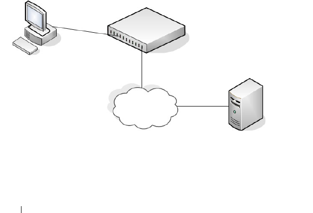
504 Configuring Port and System Security
IEEE 802.1X
What is IEEE 802.1X?
The IEEE 802.1X standard provides a means of preventing unauthorized
access by supplicants (clients) to the services the switch offers, such as access
to the LAN.
The 802.1X network has three components:
•
Supplicant
— The client connected to the authenticated port that
requests access to the network.
•
Authenticator
— The network device that prevents network access prior to
authentication.
•
Authentication Server
— The network server (such as a RADIUS server)
that performs the authentication on behalf of the authenticator, and
indicates whether the user is authorized to access system services.
Figure 19-1 shows the 802.1X network components.
Figure 19-1. IEEE 802.1X Network
As shown in Figure 19-1, the Dell Networking N2000, N3000, and N4000
series switches is the authenticator and enforces the supplicant (a PC) that is
attached to an 802.1X-controlled port to be authenticated by an
Authenticator
Supplicant
Authentication
Server
LAN

Configuring Port and System Security 505
authentication server (a RADIUS server). The result of the authentication
process determines whether the supplicant is authorized to access services on
that controlled port. Dell Networking switches support authentication using
remote RADIUS or TACACS servers and also support authentication using a
local authentication service.
Supported security methods for communication with remote servers include
MD5, PEAP, EAP-TTL, EAP-TTLS, and EAP-TLS. Only EAP-MD5 is
supported when using the local authentication server (IAS).
For a list of RADIUS attributes that the switch supports, see "Using RADIUS
Servers to Control Management Access" on page 232.
What are the 802.1X Port States?
The 802.1X port state determines whether to allow or prevent network traffic
on the port. A port can configured to be in one of the following 802.1X
control modes:
•Auto (default)
•MAC-based
• Force-authorized
• Force-unauthorized.
These modes control the behavior of the port. The port state is either
Authorized or Unauthorized.
If the port is in the authorized state, the port sends and receives normal
traffic without client port-based authentication. When a port is in an
unauthorized state, it ignores supplicant authentication attempts and does
not provide authentication services to the client. By default, when 802.1X is
globally enabled on the switch, all ports are in Auto, which means the port will
be unauthorized until a successful authentication exchange has taken place.
In addition to authorized, unauthorized, and automode, the 802.1X mode of
a port can be MAC based, as the following section describes.
NOTE: Only MAC-Based and Automode actually use 802.1X to authenticate.
Authorized and Unauthorized modes are manual overrides.

506 Configuring Port and System Security
What is MAC-Based 802.1X Authentication?
MAC-based authentication allows multiple supplicants connected to the
same port to each authenticate individually. For example, a 5-port hub might
be connected to a single port on the switch. Each host connected to the hub
must authenticate separately in order to gain access to the network.
The hosts are distinguished by their MAC addresses.
When multiple hosts (for example, a PC, a printer, and a phone in the same
office) are connected to the switch on the same port, each of the connected
hosts authenticates separately with the RADIUS server.
If a port uses MAC-based 802.1X authentication, the option to use MAC
Authentication Bypass (MAB) is available. MAB is a supplemental
authentication mechanism that allows 802.1X unaware clients – such as
printers, fax machines, and some IP phones — to authenticate to the network
using the client MAC address as an identifier.
The known and allowable MAC address and corresponding access rights of
the client must be pre-populated in the authentication server.
When a port configured for MAB receives traffic from an unauthenticated
client, the switch (Authenticator):
• Sends a EAP Request packet to the unauthenticated client
• Waits a pre-determined period of time for a response
• Retries – resends the EAP Request packet up to three times
• Considers the client to be 802.1X unaware client (if it does not receive an
EAP response packet from that client)
The authenticator sends a request to the authentication server with the MAC
address of the client in a hexadecimal format as the username and the MD5
hash of the MAC address as the password. The authentication server checks
its database for the authorized MAC addresses and returns an Access-Accept
or an Access-Reject response, depending on whether the MAC address is
found in the database. MAB also allows 802.1X-unaware clients to be placed
in a RADIUS-assigned VLAN or to apply a specific Filter ID to the client
traffic.
NOTE: By default, all ports are in VLAN Access mode. A port that uses MAC-
based authentication should be configured to be in General mode.

Configuring Port and System Security 507
What is the Role of 802.1X in VLAN Assignment?
Dell Networking series switches allow a port to be placed into a particular
VLAN based on the result of the authentication or type of 802.1X
authentication a client uses when it accesses the switch. The authentication
server can provide information to the switch about which VLAN to assign the
supplicant.
When a host connects to a switch that uses an authentication server to
authenticate, the host authentication can typically have one of three
outcomes:
• The host is authenticated.
• The host attempts to authenticate but fails because it lacks certain
security credentials.
• The host is a guest and does not try to authenticate at all (802.1X unaware).
You can create three separate VLANs on the switch to handle a host
depending on whether the host authenticates, fails the authentication, or is a
guest. The RADIUS server informs the switch of the selected VLAN as part of
the authentication.
Authenticated and Unauthenticated VLANs
Hosts that authenticate normally use a VLAN that includes access to network
resources. Hosts that fail the authentication might be denied access to the
network or placed on a
quarantine
VLAN with limited network access.
Much of the configuration to assign authenticated hosts to a particular VLAN
takes place on the 802.1X authenticator server (for example, a RADIUS
server). If you use an external RADIUS server to manage VLANs, you
configure the server to use Tunnel attributes in Access-Accept messages in
order to inform the switch about the selected VLAN. These attributes are
defined in RFC 2868, and their use for dynamic VLAN is specified in RFC
3580.
The VLAN attributes defined in RFC3580 are as follows:
• Tunnel-Type=VLAN (13)
NOTE: MAB initiates only after the dot1x guest VLAN period times out. If the client
responds to any of the EAPOL identity requests, MAB does not initiate for that
client.

508 Configuring Port and System Security
• Tunnel-Medium-Type=802
• Tunnel-Private-Group-ID=VLANID
VLANID is 12-bits and has a value between 1 and 4093.
Dynamic VLAN Creation
If RADIUS-assigned VLANs are enabled though the Authorization Network
RADIUS configuration option, the RADIUS server is expected to include the
VLAN ID in the 802.1X tunnel attributes of its response message to the
switch. If dynamic VLAN creation is enabled on the switch and the RADIUS-
assigned VLAN does not exist, then the assigned VLAN is dynamically
created. This implies that the client can connect from any port and can get
assigned to the appropriate VLAN. This gives flexibility for clients to move
around the network without much additional configuration required.
Guest VLAN
The Guest VLAN feature allows a switch to provide a distinguished service to
unauthenticated users. This feature provides a mechanism to allow users
access to hosts on the guest VLAN. For example, a company might provide a
guest VLAN to visitors and contractors to permit network access that allows
visitors to connect to external network resources, such as the Internet, with
no ability to browse information on the internal LAN.
In port-based 802.1X mode, when a client that does not support 802.1X is
connected to an unauthorized port that is 802.1X-enabled, the client does not
respond to the 802.1X requests from the switch. Therefore, the port remains
in the unauthorized state, and the client is not granted access to the network.
If a guest VLAN is configured for that port, then the port is placed in the
configured guest VLAN and the port is moved to the authorized state,
allowing access to the client. However, if the port is in MAC-based 802.1X
authentication mode, it will not move to the authorized state. MAC-based
mode makes it possible for both authenticated and guest clients to use the
same port at the same time.
Client devices that are 802.1X-supplicant-enabled authenticate with the
switch when they are plugged into the 802.1X-enabled switch port. The
switch verifies the credentials of the client by communicating with an
NOTE: MAB and the guest VLAN feature are mutually exclusive on a port.

Configuring Port and System Security 509
authentication server. If the credentials are verified, the authentication server
informs the switch to
unblock
the switch port and allows the client
unrestricted access to the network; i.e., the client is a member of an internal
VLAN.
Guest VLAN mode can be configured on a per-port basis. If a client does not
attempt authentication on a port, and the port is configured for the guest
VLAN, the client is assigned to the guest VLAN configured on that port. The
port is assigned a guest VLAN ID and is moved to the authorized status.
When the guest VLAN is disabled, users authorized by the guest VLAN are
removed.
What is Monitor Mode?
The monitor mode is a special mode that can be enabled in conjunction with
802.1X authentication. Monitor mode provides a way for network
administrators to identify possible issues with the 802.1X configuration on
the switch without affecting the network access to the users of the switch. It
allows network access even in case where there is a failure to authenticate but
logs the results of the authentication process for diagnostic purposes.
The monitor mode can be configured globally on a switch. If the switch fails
to authenticate a user for any reason (for example, RADIUS access reject
from RADIUS server, RADIUS timeout, or the client itself is dot1x-unaware),
the client is authenticated and is undisturbed by the failure condition(s). The
reasons for failure are logged for tracking purposes.
Table 19-1 provides a summary of the 802.1X Monitor Mode behavior.
Table 19-1. IEEE 802.1X Monitor Mode Behavior
Case Sub-case Regular Dot1x Dot1x Monitor Mode
RADIUS/IAS
Success
Success Port State: Permit
VLAN: Assigned
Filter: Assigned
Port State: Permit
VLAN: Assigned
Filter: Assigned
Incorrect NAS Port Port State: Deny Port State: Permit
VLAN: Default PVID
of the port
Invalid VLAN
Assignment
Port State: Deny Port State: Permit
VLAN: Default PVID
of the port

510 Configuring Port and System Security
Invalid Filter-id Port State: Deny Port State: Permit
VLAN: Default PVID
of the port
Bad RADIUS packet Port State: Deny Port State: Permit
VLAN: Default PVID
of the port
RADIUS/IAS
Failure
Default behavior Port State: Deny Port State: Permit
VLAN: Default PVID
of the port
Unauth VLAN
enabled
Port State: Permit
VLAN: Unauth
Port State: Permit
VLAN: Unauth
RADIUS
Timeout
Default behavior Port State: Deny Port State: Permit
VLAN: Default PVID
of the port
Unauth VLAN
enabled
Port State: Deny Port State: Permit
VLAN: Unauth
EAPOL Timeout Default behavior Port State: Deny Port State: Permit
3 × EAPOL
Timeout
(Guest VLAN
timer expiry or
MAB timer
expiry)
Guest VLAN
enabled
Port State: Permit
VLAN: Guest
Port State: Permit
VLAN: Guest
MAB Success Case Port State: Permit
VLAN: Assigned
Filter: Assigned
Port State: Permit
VLAN: Assigned
Filter: Assigned
MAB Fail Case
Port State: Deny Port State: Permit
VLAN: Default PVID
of the port
Supplicant
Timeout
Port State: Deny Port State: Deny
Table 19-1. IEEE 802.1X Monitor Mode Behavior (Continued)
Case Sub-case Regular Dot1x Dot1x Monitor Mode

Configuring Port and System Security 511
How Does the Authentication Server Assign DiffServ Filters?
The Dell Networking series switches allow the external 802.1X Authenticator
or RADIUS server to assign DiffServ policies to users that authenticate to the
switch. When a host (supplicant) attempts to connect to the network
through a port, the switch contacts the 802.1X authenticator or RADIUS
server, which then provides information to the switch about which DiffServ
policy to assign the host (supplicant). The application of the policy is applied
to the host after the authentication process has completed.
For additional guidelines about using an authentication server to assign
DiffServ policies, see "Configuring Authentication Server DiffServ Filter
Assignments" on page 535.
What is the Internal Authentication Server?
The Internal Authentication Server (IAS) is a dedicated database for localized
authentication of users for network access through 802.1X. In this database,
the switch maintains a list of username and password combinations to use for
802.1X authentication. You can manually create entries in the database, or
you can upload the IAS information to the switch.
If the authentication method for 802.1X is IAS, the switch uses the locally
stored list of username and passwords to provide port-based authentication to
users instead of using an external authentication server. Authentication using
the IAS supports the EAP-MD5 method only.
Default 802.1X Values
Table 19-2 lists the default values for the 802.1X features.
Port/Client
Authenticated
on Guest VLAN
Delete Guest
VLANID through
Dot1Q
Port State: Deny Port State: Permit
VLAN: Default PVID
of the port
NOTE: The IAS database does not handle VLAN assignments or DiffServ policy
assignments.
Table 19-1. IEEE 802.1X Monitor Mode Behavior (Continued)
Case Sub-case Regular Dot1x Dot1x Monitor Mode

512 Configuring Port and System Security
Configuring IEEE 802.1X (Web)
This section provides information about the OpenManage Switch
Administrator pages for configuring and monitoring the IEEE 802.1X
features and Port Security on a Dell Networking N2000, N3000, and N4000
Table 19-2. Default Port-Based Security Values
Feature Description
Global 802.1X status Disabled
802.1X authentication method none
Per-port 802.1X status Disabled
Port state automode
Periodic reauthentication Disabled
Seconds between reauthentication
attempts
3600
Authentication server timeout 30 seconds
Resending EAP identity Request 30 seconds
Quiet period 60 seconds
Supplicant timeout 30 seconds
Max EAP request 2 times
Maximum number of supplicants per port
for MAC-based authentication mode
16
Guest VLAN Disabled
Unauthenticated VLAN Disabled
Dynamic VLAN creation Disabled
RADIUS-assigned VLANs Disabled
IAS users none configured
Port security Unlocked
Port security traps Disabled
Maximum learned MAC addresses 100 (when locked)
Monitor mode Disabled

Configuring Port and System Security 513
series switches. For details about the fields on a page, click at the top of
the page.
Dot1x Authentication
Use the Dot1x Authentication
page
to configure the 802.1X administrative
mode on the switch and to configure general 802.1X parameters for a port.
To display the Dot1x Authentication
page, click Switching
→
Network
Security
→
Dot1x Authentication
→
Authentication in the navigation panel.
Figure 19-2. Dot1x Authentication
To configure 802.1X authentication on multiple ports:
1
Open the
Dot1x Authentication
page.
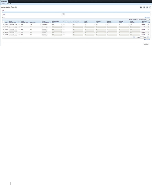
514 Configuring Port and System Security
2
Click
Show All
to display the
Dot1x Authentication
Table
page.
3
In the Ports list, select the check box in the
Edit
column for the port to
configure.
4
Select the desired settings to change for all ports that are selected for
editing.
Figure 19-3. Configure Dot1x Settings
5
Click
Apply
.
To reauthenticate a port:
1
Open the
Dot1x Authentication
page.
2
Click
Show All
.
The
Dot1x Authentication
Table
displays.
3
Check
Edit
to select the Unit/Port to re-authenticate.
4
Check
Reauthenticate Now
.
5
Click
Apply
.
The authentication process is restarted on the specified port.
To reauthenticate multiple ports:
1
Open the
Dot1x Authentication
page.
2
Click
Show All
.
The
Dot1x Authentication
Table
displays.
3
Check
Edit
to select the Units/Ports to re-authenticate.
4
To re-authenticate on a periodic basis, set
Periodic Re-Authentication
to
Enable, and specify a
Re-Authentication Period
for all desired ports.

Configuring Port and System Security 515
5
To re-authenticate immediately, check
Reauthenticate Now
for all ports to
be re-authenticated.
6
Click
Apply
.
The authentication process is restarted on the specified ports (either
immediately or periodically).
To change the administrative port control:
1
Open the
Dot1x Authentication
page.
2
Click
Show All
.
The
Dot1x Authentication
Table
displays.
3
Scroll to the right side of the table and select the
Edit
check box for each
port to configure. Change
Admin Port Control
to
Authorized
,
Unauthorized
, or
Automode
as needed for chosen ports. Only
MAC-
Based
and
Automode
actually use 802.1X to authenticate.
Authorized
and
Unauthorized
are manual overrides.
4
Click
Apply
.
Admin Port Control is updated for the specified ports, and the device is
updated.
Authenticated Users
The Authenticated Users page is used to display lists of ports that have
authenticated users.
To display the Authenticated Users page, click Switching
→
Network
Security
→
Authenticated Users in the navigation panel.
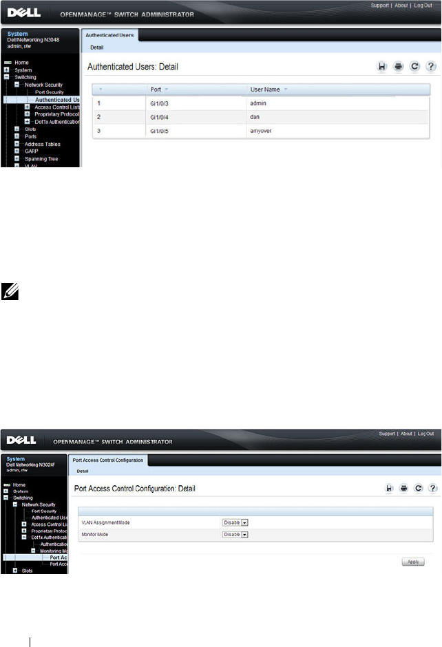
516 Configuring Port and System Security
Figure 19-4. Network Security Authenticated Users
Port Access Control Configuration
Use the Port Access Control Configuration page to globally enable or disable
RADIUS-assigned VLANs and to enable Monitor Mode to help troubleshoot
802.1X configuration issues.
To display the Port Access Control Configuration page, click Switching
→
Network Security
→
Dot1x Authentication
→
Monitor Mode
→
Port Access
Control Configuration in the navigation panel.
Figure 19-5. Port Access Control Configuration
NOTE: The VLAN Assignment Mode field is the same as the Admin Mode field on
the System → Management Security → Authorization Network RADIUS page.
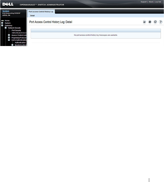
Configuring Port and System Security 517
Port Access Control History Log Summary
Use the Port Access Control History Log Summary page to view log messages
about 802.1X client authentication attempts. The information on this page
can help you troubleshoot 802.1X configuration issues.
To display the Port Access Control History Log Summary page, click Port
Access Control Configuration page, click Switching
→
Network Security
→
Dot1x Authentication
→
Monitor Mode
→
Port Access Control History Log
Summary in the navigation panel.
Figure 19-6. Port Access Control History Log Summary
Internal Authentication Server Users Configuration
Use the Internal Authentication Server Users Configuration page to add
users to the local IAS database and to view the database entries.
To display the Internal Authentication Server Users Configuration page,
click System
→
Management Security
→
Internal Authentication Server
Users Configuration in the navigation panel.
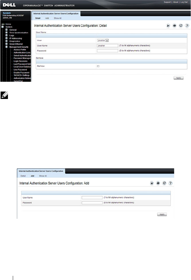
518 Configuring Port and System Security
Figure 19-7. Internal Authentication Server Users Configuration
To add IAS users:
1
Open the
Internal Authentication Server Users Configuration
page.
2
Click
Add
to display the
Internal Authentication Server Users Add
page.
3
Specify a username and password in the appropriate fields.
Figure 19-8. Adding an IAS User
4
Click
Apply
.
To view the Internal Authentication Server Users Table page, click Show All.
To delete an IAS user:
1
Open the
Internal Authentication Server Users Configuration
page.
NOTE: If no users exist in the IAS database, the IAS Users Configuration Page
does not display the fields shown in the image.
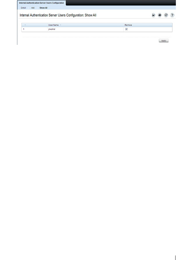
Configuring Port and System Security 519
2
From the User menu, select the user to remove, select the user to remove.
3
Select the
Remove
check box
.
Figure 19-9. Removing an IAS User
4
Click
Apply
.

520 Configuring Port and System Security
Configuring IEEE 802.1X (CLI)
This section provides information about commands you use to configure
802.1X and Port Security settings. For additional information about the
commands in this section, see the
Dell Networking N2000, N3000, and
N4000 Series Switches CLI Reference Guide
at support.dell.com/manuals.
Configuring Basic 802.1X Authentication Settings
Beginning in Privileged EXEC mode, use the following commands to enable
and configure 802.1X authentication on the switch.
Command Purpose
configure Enter Global Configuration mode.
aaa accounting dot1x
default
Sets 802.1X accounting to the default operational mode
aaa authentication
dot1x default
method1
Specify the authentication method to use to authenticate
802.1X clients that connect to the switch.
method1
—The method keyword can be radius, none, or
ias.
dot1x system-auth-
control
Globally enable 802.1X authentication on the switch.
interface
interface
Enter interface configuration mode for the specified
interface. The
interface
variable includes the interface type
and number, for example tengigabitethernet 1/0/3.
You can also specify a range of interfaces with the interface
range command, for example, interface range
tengigabitethernet 1/0/8-12 configures interfaces 8, 9, 10,
11, and 12.

Configuring Port and System Security 521
dot1x port-control
{force-authorized |
force-unauthorized |
auto | mac-based}
Specify the 802.1X mode for the port.
NOTE: For standard 802.1X implementations in which one
client is connected to one port, use the dot1x port-control
auto command to enable 802.1X authentication on the port.
•
auto
— Enables 802.1X authentication on the interface
and causes the port to transition to the authorized or
unauthorized state based on the 802.1X authentication
exchange between the switch and the client.
•
force-authorized
— Disables 802.1X authentication on
the interface and causes the port to transition to the
authorized state without any authentication exchange
required. The port sends and receives normal traffic
without 802.1X-based authentication of the client.
•
force-unauthorized
— Denies all access through this
interface by forcing the port to transition to the
unauthorized state, ignoring all attempts by the client to
authenticate. The switch cannot provide authentication
services to the client through the interface.
•
mac-based
— Enables 802.1X authentication on the
interface and allows multiple hosts to authenticate on a
single port. The hosts are distinguished by their MAC
addresses.
dot1x mac-auth-bypass If the 802.1X mode on the interface is mac-based, you can
optionally use this command to enable MAB on an
interface.
CTRL + Z Exit to Privileged EXEC mode.
show dot1x View the current 802.1X configuration.
show dot1x clients {all |
interface
}
View information about 802.1X clients that have
successfully authenticated and are connected to the
switch. The
interface
variable includes the interface type
and number.
show dot1x users
[username
username
]
View the 802.1X authenticated users for the switch.
Command Purpose

522 Configuring Port and System Security
Configuring Additional 802.1X Interface Settings
Beginning in Privileged EXEC mode, use the following commands to
configure 802.1X interface settings such as the reauthentication period and
switch-to-client retransmission time.
NOTE: To enable 802.1X Monitor Mode to help troubleshoot authentication issues,
use the dot1x system-auth-control monitor command in Global Configuration
mode. To view 802.1X authentication events and information, use the show dot1x
authentication-history {<
interface
> | all} [failed-auth-only] [detail] command in
Privileged EXEC mode. To clear the history, use the clear dot1x authentication-
history command.
Command Purpose
configure Enter Global Configuration mode.
interface
interface
Enter interface configuration mode for the specified
interface. The
interface
variable includes the interface type
and number, for example tengigabitethernet 1/0/3.
You can also specify a range of interfaces with the interface
range command, for example, interface range
tengigabitethernet 1/0/8-12 configures interfaces 8, 9, 10,
11, and 12.
dot1x reauthentication Enable periodic re-authentication of the client.
dot1x timeout re-
authperiod
seconds
Set the number of seconds between re-authentication
attempts.
dot1x timeout server-
timeout
seconds
Set the time that the switch waits for a response from the
authentication server.
dot1x timeout tx-period
seconds
Set the number of seconds that the switch waits for a
response to an Extensible Authentication Protocol (EAP)-
request/identity frame from the client before resending the
request.
dot1x timeout quiet-
period
seconds
Set the number of seconds that the switch remains in the
quiet state following a failed authentication exchange (for
example, the client provided an invalid password).

Configuring Port and System Security 523
Configuring 802.1X Settings for RADIUS-Assigned VLANs
Beginning in Privileged EXEC mode, use the following commands to
configure 802.1X settings that affect the RADIUS-assigned VLAN.
dot1x timeout supp-
timeout
seconds
Set the time that the switch waits for a response before
retransmitting an Extensible Authentication Protocol
(EAP)-request frame to the client.
dot1x max-req
count
Set the maximum number of times that the switch sends
an Extensible Authentication Protocol (EAP)-request
frame (assuming that no response is received) to the client
before restarting the authentication process.
dot1x max-users
users
Set the maximum number of clients supported on the port
when MAC-based 802.1X authentication is enabled on the
port.
CTRL + Z Exit to Privileged EXEC mode.
dot1x re-authenticate
[
interface
]
Manually initiate the re-authentication of all 802.1X-
enabled ports or on the specified 802.1X-enabled port.
The
interface
variable includes the interface type and
number.
dot1x initialize
[
interface
]
Start the initialization sequence on all ports or on the
specified port.
NOTE: This command is valid only if the port-control mode
for the specified port is auto or MAC-based.
show dot1x [interface
interface]
View 802.1X settings for the switch or for the specified
interface.
show dot1x interface
interface
statistics
View 802.1X statistics for the specified interface.
Command Purpose
configure Enter Global Configuration mode.
aaa authorization
network default radius
Allow the RADIUS server to assign VLAN IDs to clients.
Command Purpose

524 Configuring Port and System Security
dot1x dynamic-vlan
enable
If the RADIUS assigned VLAN does not exist on the
switch, allow the switch to dynamically create the assigned
VLAN.
interface
interface
Enter interface configuration mode for the specified
interface. The
interface
variable includes the interface type
and number, for example tengigabitethernet 1/0/3.
You can also specify a range of interfaces with the interface
range command, for example, interface range
tengigabitethernet 1/0/8-12 configures interfaces 8, 9, 10,
11, and 12.
dot1x guest-vlan
vlan-id
Specify the guest VLAN.
dot1x unauth-vlan
vlan-
id
Specify the unauthenticated VLAN. The VLAN must
already have been created.
CTRL + Z Exit to Privileged EXEC mode.
show dot1x advanced
interface
View the current 802.1X configuration.
NOTE: When dynamically creating VLANs, the uplink port should be in trunk
mode so that it will automatically participate in all dynamically-created VLANs.
Otherwise, the supplicant may be placed in a VLAN that does not go beyond the
switch because no other ports are participating.
Command Purpose

Configuring Port and System Security 525
Configuring Internal Authentication Server Users
Beginning in Privileged EXEC mode, use the following commands to add
users to the IAS database and to use the database for 802.1X authentication.
IEEE 802.1X Configuration Examples
This section contains the following examples:
• Configuring 802.1X Authentication
• Controlling Authentication-Based VLAN Assignment
• Allowing Dynamic VLAN Creation of RADIUS-Assigned VLANs
• Configuring Authentication Server DiffServ Filter Assignments
Configuring 802.1X Authentication
The network in this example requires clients to use 802.1X authentication to
access the network through the switch ports. The administrator must
configure the following settings on systems other than the switch before
configuring the switch:
1
Add the users to the client database on the Authentication Server, such as
a RADIUS server with Cisco
®
Secure Access Control Server (ACS)
software.
2
Configure the settings on the client, such a PC running Microsoft
®
Windows, to require 802.1X authentication.
Command Purpose
configure Enter Global Configuration mode.
aaa ias-user username
user
Add a user to the IAS user database. This command also
changes the mode to the AAA User Config mode.
password
password
[encrypted]
Configure the password associated with the user.
CTRL + Z Exit to Privileged EXEC mode.
show aaa ias-users View all configured IAS users.
clear aaa ias-users Delete all IAS users from the database.

526 Configuring Port and System Security
The switch uses an authentication server with an IP address of 10.10.10.10 to
authenticate clients. Port 7 is connected to a printer in the unsecured area.
The printer is an 802.1X unaware client, so Port 7 is configured to use MAC-
based authentication with MAB.
An IP phone is directly connected to Port 8, and a PC is connected to the IP
phone. Both devices are authenticated through MAC-based authentication,
which allows multiple hosts to authenticate on a single port. The hosts are
distinguished by their MAC addresses, and hosts authenticate separately with
the RADIUS server.
Port 9 is connected to a server in a part of the network that has secure physical
access (i.e. the doors to the wiring closet and data center are locked), so this
port is set to the Authorized state, meaning that the device connected to this
port does not need to authenticate using 802.1X. Port 24 is the uplink to a
router and is also in the Authorized state.
NOTE: The printer requires an entry in the client database that uses the printer
MAC address as the username.
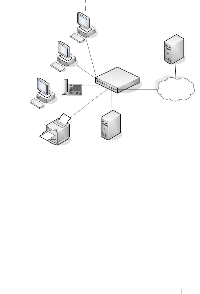
Configuring Port and System Security 527
Figure 19-10. 802.1X Example
The following example shows how to configure the example shown in
Figure 19-10.
1
Configure the RADIUS server IP address and shared secret (
secret
).
console#configure
console(config)#radius-server host 10.10.10.10
console(Config-radius)#exit
console(config)#radius-server key secret
console(config)#exit
2
Enable 802.1X port-based access control on the switch.
console(config)#dot1x system-auth-control
3
Configure ports 9 and 24 to be in the Authorized state, which allows the
devices to connect to these ports to access the switch services without
authentication.
console(config)#interface range Gi1/0/9,Gi1/0/24
Authentication Server
(RADIUS)
LAN
Dell Networking Switch
Server
(Port 9)
Clients
(Ports 1 and 3)
Printer
(Port 7)
LAN Uplink
(Port 24)
Physically Unsecured Devices Physically Secured Devices
Clients
(Port 8)

528 Configuring Port and System Security
console(config-if)#dot1x port-control force-
authorized
console(config-if)#exit
4
Configure Port 7 to require MAC-based authentication with MAB.
console(config)#interface gi1/0/7
console(config-if-Gi1/0/7)#dot1x port-control mac-
based
console(config-if-Gi1/0/7)#dot1x mac-auth-bypass
5
Set the port to an 802.1Q VLAN. The port must be in general mode in
order to enable MAC-based 802.1X authentication.
console(config-if-Gi1/0/7)#switchport mode general
console(config-if-Gi1/0/7)#exit
6
Enable MAC-based authentication on port 8 and limit the number of
devices that can authenticate on that port to 2.
console(config)#interface gi1/0/8
console(config-if-Gi1/0/8)#dot1x port-control mac-
based
console(config-if-Gi1/0/8)#dot1x max-users 2
7
Set Port 8 to switchport mode general. The port must be in general mode
in order to enable MAC-based 802.1X authentication.
console(config-if-Gi1/0/8)#switchport mode general
console(config-if-Gi1/0/8)#exit
console(config)#exit
8
View the client connection status.
When the clients on Ports 1, 3, and 7(supplicants), attempt to
communicate via the switch, the switch challenges the supplicants for
802.1X credentials. The switch encrypts the provided information and
transmits it to the RADIUS server. If the RADIUS server grants access, the
system sets the 802.1X port state of the interface to authorized and the
supplicants are able to access network resources.
console#show dot1x clients all
Interface...................................... Gi1/0/1
User Name...................................... aoversmit
Supp MAC Address............................... 0012.1753.031A
Session Time................................... 756

Configuring Port and System Security 529
Filter Id......................................
VLAN Assigned.................................. 1 (Default)
Interface...................................... Gi1/0/3
User Name...................................... dflint
Supp MAC Address............................... 0004.5A55.EFAD
Session Time................................... 826
Filter Id......................................
VLAN Assigned.................................. 1 (Default)
Interface...................................... Gi1/0/7
User Name...................................... 0006.6B33.06BA
Supp MAC Address............................... 0006.6B33.06BA
Session Time................................... 826
Filter Id......................................
VLAN Assigned.................................. 1 (Default)
9
View a summary of the port status.
console#show dot1x
Administrative Mode............... Enabled
Port Admin Oper Reauth Reauth
Mode Mode Control Period
------- ---------------- ------------ -------- ----------
Gi1/0/1 auto Authorized FALSE 3600
Gi1/0/2 auto N/A FALSE 3600
Gi1/0/3 auto Authorized FALSE 3600
Gi1/0/4 auto N/A FALSE 3600
Gi1/0/5 auto N/A FALSE 3600
Gi1/0/6 auto N/A FALSE 3600
Gi1/0/7 mac-based Authorized FALSE 3600
Gi1/0/8 mac-based N/A FALSE 3600
Gi1/0/9 force-authorized Authorized FALSE 3600
Gi1/0/10 force-authorized Authorized FALSE 3600
Gi1/0/11 auto N/A FALSE 3600
--More-- or (q)uit

530 Configuring Port and System Security
10
View 802.1X information about Port 8.
console#show dot1x interface Gi1/0/8
Administrative Mode............... Enabled
Dynamic VLAN Creation Mode........ Enabled
Monitor Mode...................... Disabled
Port Admin Oper Reauth Reauth
Mode Mode Control Period
------- ---------------- ------------ -------- ----------
Gi1/0/8 mac-based Authorized FALSE 3600
Quiet Period................................... 60
Transmit Period................................ 30
Maximum Requests............................... 2
Max Users...................................... 2
VLAN Assigned.................................. 1 (Default)
Supplicant Timeout............................. 30
Guest-vlan Timeout............................. 90
Server Timeout (secs).......................... 30
MAB mode (configured).......................... Disabled
MAB mode (operational)......................... Disabled
Controlling Authentication-Based VLAN Assignment
The network in this example uses three VLANs to control access to network
resources. When a client connects to the network, it is assigned to a particular
VLAN based on one of the following events:
• It attempts to contact the 802.1X server and is authenticated.
• It attempts to contact the 802.1X server and fails to authenticate.
• It does not attempt to contact the 802.1X server.
The following table describes the three VLANs:
VLAN ID VLAN Name VLAN Purpose
100 Authorized Data from authorized clients
200 Unauthorized Data traffic from clients that fail the authentication
with the RADIUS server
300 Guest Data traffic from clients that do not attempt to
authenticate with the RADIUS server

Configuring Port and System Security 531
The commands in this example show how to configure the switch to control
VLAN assignment for the example network. This example also contains
commands to configure the uplink, or trunk, port (a port connected to a
router or the internal network), and to configure the downlink, or access,
ports (ports connected to one or more hosts). Ports 1–23 are downstream
ports. Port 24 is an uplink port. An external RADIUS server handles the
VLAN assignment.
NOTE: Dynamic VLAN creation applies only to authorized ports. The VLANs for
unauthorized and guest users must be configured on the switch and cannot be
dynamically created based on RADIUS-based VLAN assignment.
NOTE: The configuration to control the VLAN assignment for authorized users is
done on the external RADIUS server.

532 Configuring Port and System Security
To configure the switch:
1
Create the VLANs and configure the VLAN names.
console(config)#vlan 100
console(config-vlan100)#name Authorized
console(config-vlan100)#exit
console(config)#vlan 200
console(config-vlan200)#name Unauthorized
console(config-vlan200)#exit
console(config)#vlan 300
console(config-vlan300)#name Guest
console(config-vlan300)#exit
2
Configure information about the external RADIUS server the switch uses
to authenticate clients. The RADIUS server IP address is 10.10.10.10, and
the shared secret is qwerty123.
console(config)#radius-server key qwerty123
console(config)#radius-server host 10.10.10.10
console(Config-auth-radius)#exit
3
Enable 802.1X on the switch.
console(config)#dot1x system-auth-control
4
Create a default authentication login list and use the RADIUS server for
port-based authentication for connected clients.
console(config)#aaa authentication dot1x default
radius
5
Allow the switch to accept VLAN assignments by the RADIUS server.
console(config)#aaa authorization network default
radius
6
Enter interface configuration mode for the downlink ports.
console(config)#interface range Gi1/0/1-23
7
Set the downlink ports to the access mode because each downlink port
connects to a single host that belongs to a single VLAN.
console(config-if)#switchport mode access

Configuring Port and System Security 533
8
Enable periodic reauthentication of the client on the ports and set the
number of seconds to wait between reauthentication attempts to 300
seconds. Reauthentication is enabled to increase security. If the client
information is removed from the RADIUS server after it has been
authenticated, the client will be denied access when it attempts to
reauthenticate.
console(config-if)#dot1x reauthentication
console(config-if)#dot1x timeout re-authperiod 300
9
Set the unauthenticated VLAN on the ports to VLAN 200 so that any
client that connects to one of the ports and fails the 802.1X authentication
is placed in VLAN 200.
console(config-if)#dot1x unauth-vlan 200
10
Set the guest VLAN on the ports to VLAN 300. This command
automatically enables the Guest VLAN Mode on the downlink ports. Any
client that connects to the port and does not attempt to authenticate is
placed on the guest VLAN.
console(config-if)#dot1x guest-vlan 300
console(config-if)#exit
11
Enter Interface Configuration mode for port 24, the uplink (trunk) port.
console(config)#interface Gi1/0/24
12
Disable 802.1X authentication on the interface. This causes the port to
transition to the authorized state without any authentication exchange
required. This port does not connect to any end-users, so there is no need
for 802.1X-based authentication.
console(config-if-Gi1/0/24)#dot1x port-control
force-authorized
13
Set the uplink port to trunk mode so that it accepts tagged traffic and
transmits it to the connected device (another switch or router).
console(config-if-Gi1/0/24)#switchport mode trunk

534 Configuring Port and System Security
Allowing Dynamic VLAN Creation of RADIUS-Assigned VLANs
The network in this example uses a RADIUS server to provide VLAN
assignments to host that connect to the switch. In this example, the VLANs
are not configured on the switch. Instead, the switch is configured to allow
the dynamic creation of VLANs when a RADIUS-assigned VLAN does not
already exist on the switch.
In this example, Ports 1–23 are configured as downlink, or access, ports, and
Port 24 is the trunk port. As a trunk port, Port 24 is automatically added as a
member to all VLANs that are statically or dynamically configured on the
switch. However, the network administrator in this example has determined
that traffic in VLANs 1000–2000 should not be forwarded on the trunk port,
even if the RADIUS server assigns a connected host to a VLAN in this range,
and the switch dynamically creates the VLAN.
To configure the switch:
1
Configure information about the external RADIUS server the switch uses
to authenticate clients. The RADIUS server IP address is 10.10.10.10, and
the shared secret is qwerty123.
console(config)#radius-server key qwerty123
console(config)#radius-server host 10.10.10.10
console(Config-auth-radius)#exit
2
Enable 802.1X on the switch.
console(config)#dot1x system-auth-control
3
Create a default authentication login list and use the RADIUS server for
port-based authentication for connected clients.
console(config)#aaa authentication dot1x default
radius
4
Allow the switch to accept VLAN assignments by the RADIUS server.
console(config)#aaa authorization network default
radius
NOTE: The configuration to control the VLAN assignment for hosts is done on
the external RADIUS server.

Configuring Port and System Security 535
5
Allow the switch to dynamically create VLANs when a RADIUS-assigned
VLAN does not exist on the switch.
console(config)#dot1x dynamic-vlan enable
6
Enter interface configuration mode for the downlink ports.
console(config)#interface range Gi1/0/1-23
7
Set the downlink ports to the access mode because each downlink port
connects to a single host that belongs to a single VLAN.
console(config-if)#switchport mode access
console(config-if)#exit
8
Enter Interface Configuration mode for port 24, the uplink (trunk) port.
console(config)#interface Gi1/0/24
9
Disable 802.1X authentication on the interface. This causes the port to
transition to the authorized state without any authentication exchange
required. This port does not connect to any end-users, so there is no need
for 802.1X-based authentication.
console(config-if-Gi1/0/24)#dot1x port-control
force-authorized
10
Set the uplink port to trunk mode so that it accepts tagged traffic and
transmits it to the connected device (another switch or router).
console(config-if-Gi1/0/24)#switchport mode trunk
11
Forbid the trunk from forwarding traffic that has VLAN tags for any VLAN
from 1000–2000, inclusive.
console(config-if-Gi1/0/24)#switchport trunk
allowed vlan remove 1000-2000
console(config-if-Gi1/0/24)#exit
Configuring Authentication Server DiffServ Filter Assignments
To enable DiffServ filter assignment by an external server, the following
conditions must be true:
• The port that the host is connected to must be enabled for MAC-based
port access control by using the following command in Interface Config
mode:
dot1x port-control mac-based

536 Configuring Port and System Security
• The RADIUS or 802.1X server must specify the policy to assign.
For example, if the DiffServ policy to assign is named internet_access,
include the following attribute in the RADIUS or 802.1X server
configuration:
Filter-id = “internet_access”
• The DiffServ policy specified in the attribute must already be configured
on the switch, and the policy names must be identical.
For information about configuring a DiffServ policy, see "DiffServ
Configuration Examples" on page 1307. The example "Providing Subnets
Equal Access to External Network" on page 1307, describes how to
configure a policy named internet_access.
If you use an authentication server to assign DiffServ policies to an
authenticated user, note the following guidelines:
• If the policy specified within the server attribute does not exist on the
switch, authentication will fail.
• Do not delete policies used as the filter ID in the RADIUS server while
802.1X is enabled.
• Do not use the DiffServ
service-policy
command to apply the filter to an
interface if you configure the RADIUS server or 802.1X authenticator to
assign the DiffServ filter.
In the following example, Company XYZ uses IEEE 802.1X to authenticate
all users. Contractors and temporary employees at Company XYZ are not
permitted to have access to SSH ports, and data rates for Web traffic is
limited. When a contractor is authenticated by the RADIUS server, the server
assigns a DiffServ policy to control the traffic restrictions.
The network administrator configures two DiffServ classes:
cl-ssh
and
cl-http
.
The class
cl-ssh
matches all incoming SSH packets. The class
cl-http
matches
all incoming HTTP packets. Then, the administrator configures a traffic
policy called
con-pol
and adds the
cl-ssh
and
cl-http
. The policy is configured
so that that SSH packets are to be dropped, and HTTP data rates are limited
to 1 MB with a burst size of 64 Kbps. HTTP traffic that exceeds the limit is
dropped.
The host ports, ports 1–23, are configured to use MAC-based dot1x
authentication to allow the DiffServ policy to be applied. Finally,
the
administrator configures the RADIUS server with the attribute
Filter-id =
“con-pol”.

Configuring Port and System Security 537
To configure the switch:
1
Configure the DiffServ traffic class that matches SSH traffic.
console#configure
console(config)#class-map match-all cl-ssh
console(config-classmap)#match srcl4port 23
console(config-classmap)#exit
2
Configure the DiffServ traffic class that matches HTTP traffic.
console(config)#class-map match-all cl-http
console(config-classmap)#match srcl4port 80
console(config-classmap)#exit
3
Configure the DiffServ policy.
console(config)#policy-map con-pol in
console(config-policy-map)#class cl-ssh
console(config-policy-classmap)#drop
console(config-policy-classmap)#exit
console(config-policy-map)#class cl-http
console(config-policy-classmap)#police-simple
1000000 64 conform-action transmit violate-action
drop
console(config-policy-classmap)#exit
console(config-policy-map)#exit
4
Enable DiffServ on the switch.
console(config)#diffserv
5
Configure information about the external RADIUS server the switch uses
to authenticate clients. The RADIUS server IP address is 10.10.10.10, and
the shared secret is qwerty123.
console(config)#radius-server key qwerty123
console(config)#radius-server host 10.10.10.10
console(Config-auth-radius)#exit
6
Enable 802.1X on the switch.
console(config)#dot1x system-auth-control
7
Create a default authentication login list and use the RADIUS server for
port-based authentication for connected clients.

538 Configuring Port and System Security
console(config)#aaa authentication dot1x default
radius
8
Enter Interface Configuration mode for ports 1–23 and enable MAC-
based authentication.
console(config)#interface range Gi1/0/1-23
console(config-if)#dot1x port-control mac-based
9
Set the ports to an 802.1Q VLAN. The ports must be in general mode in
order to enable MAC-based 802.1X authentication.
console(config-if)#switchport mode general
console(config-if)#exit
console(config)#exit

Configuring Port and System Security 539
Port Security (Port-MAC Locking)
The Port Security feature allows you to limit the number of source MAC
addresses that can be learned on a port. If a port reaches the configured limit,
any other addresses beyond that limit are not learned and the frames are
discarded. Frames with a source MAC address that has already been learned
will be forwarded.
The purpose of this feature, which is also known as port-MAC locking, is to
help secure the network by preventing unknown devices from forwarding
packets into the network. For example, to ensure that only a single device can
be active on a port, you can set the number of allowable dynamic addresses to
one. After the MAC address of the first device is learned, no other devices will
be allowed to forward frames into the network.
When link goes down on a port, all of the dynamically locked addresses are
cleared from the source MAC address table the feature maintains. When the
link is restored, that port can once again learn addresses up to the specified
limit.
The port can learn MAC addresses dynamically, and you can manually specify
a list of static MAC addresses for a port.
Default 802.1X Values
Table 19-2 lists the default values for the Port Security feature.
Configuring Port Security Configuration (Web)
This section provides information about the OpenManage Switch
Administrator pages for configuring and monitoring the IEEE 802.1X
features and Port Security on a Dell Networking N2000, N3000, and N4000
series switches. For details about the fields on a page, click at the top of
the page.
Table 19-3. Default Port Security Values
Feature Description
Port security Unlocked
Port security traps Disabled
Maximum learned MAC addresses 100 (when locked)
Monitor mode Disabled
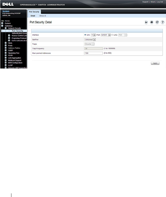
540 Configuring Port and System Security
Port Security
Use the Port Security page to enable MAC locking on a per-port basis. When
a port is locked, you can limit the number of source MAC addresses that are
allowed to transmit traffic on the port.
To display the Port Security page, click Switching
→
Network Security
→
Port Security in the navigation panel.
Figure 19-11. Network Security Port Security
Configuring Port Security Settings on Multiple Ports
To configure port security on multiple ports:
1
Open the
Port Security
page.
2
Click
Show All
to display the
Port Security
Ta bl e
page.
3
In the Ports list, select the check box in the
Edit
column for the port to
configure.
4
Select the desired settings for all ports that are selected for editing.
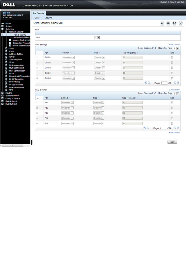
Configuring Port and System Security 541
Figure 19-12. Configure Port Security Settings
5
Click
Apply
.

542 Configuring Port and System Security
Configuring Port Security (CLI)
Beginning in Privileged EXEC mode, use the following commands to enable
port security on an interface to limit the number of source MAC addresses
that can be learned.
19
Command Purpose
configure Enter Global Configuration mode.
interface
interface
Enter interface configuration mode for the specified
interface. The
interface
variable includes the interface type
and number, for example tengigabitethernet 1/0/3.
You can also specify a range of interfaces with the interface
range command, for example, interface range
tengigabitethernet 1/0/8-12 configures interfaces 8, 9, 10,
11, and 12.
port security [discard]
[trap
seconds
]
Enable port security on the port. This prevents the switch
from learning new addresses on this port after the
maximum number of addresses has been learned.
•
discard
— Discards frames with unlearned source
addresses. This is the default if no option is indicated.
•
trap
seconds
— Sends SNMP traps and defines the
minimal amount of time in seconds between two
consecutive traps. (Range: 1–1000000)
port security max
max-
addr
Set the maximum number of MAC addresses that can be
learned on the port while port security is enabled.
CTRL + Z Exit to Privileged EXEC mode.
show ports security
[
interface
]
View port security settings on all interfaces or the specified
interface.
show ports security
addresses [
interface
]
View the current MAC addresses that have been learned
on all ports or the specified port.

Configuring Port and System Security 543
Captive Portal
This section describes how to configure the Captive Portal feature.
The topics covered in this section include:
• Captive Portal Overview
• Default Captive Portal Behavior and Settings
• Configuring the Captive Portal (Web)
• Configuring Captive Portal (CLI)
• IEEE 802.1X Configuration Examples
Captive Portal Overview
A Captive Portal helps manage or restrict network access. Captive Portals are
often used in locations that provide wired Internet access to customers, such
as business centers and hotels. For example, a hotel might provide an
Ethernet port in each room so that guests can connect to the Internet during
their stay. The hotel might charge for Internet use, or the hotel might allow
guests to connect only after they indicate that they have read and agree to the
acceptable use policy.
What Does Captive Portal Do?
The Captive Portal feature allows you to require a user to enter login
information on a custom Web page before gaining access to the network.
When the user connects to the port and opens a browser, the user is
presented with a welcome screen. To gain network access, the user must enter
a username (for guest access) or a username and password (for authenticated
access) and accept the terms of use. You can also configure the Captive Portal
feature to redirect the user to another web page after successful
authentication, for example your company home page.
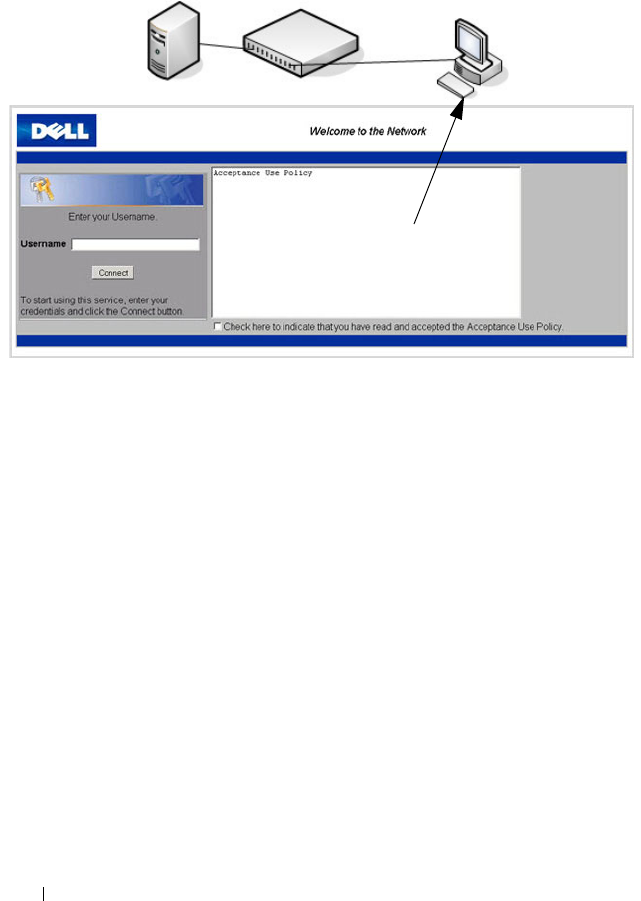
544 Configuring Port and System Security
Figure 19-13. Connecting to the Captive Portal
The Captive Portal feature blocks hosts connected to the switch from
accessing the network until user verification has been established. You can
configure Captive Portal verification to allow access for both guest and
authenticated users. Authenticated users must be validated against a
database of authorized Captive Portal users before access is granted. The
database can be stored locally on the switch or on a RADIUS server.
Is the Captive Portal Feature Dependent on Any Other Feature?
If you require RADIUS authentication, you must configure the RADIUS
server information on the switch (see "Using RADIUS Servers to Control
Management Access" on page 232). You must also configure the RADIUS
attributes for Captive Portal users on the RADIUS server. For information
about the RADIUS attributes to configure, see Table 19-5.
For a list of RADIUS attributes that the switch supports, see "Which
RADIUS Attributes Does the Switch Support?" on page 234.
Default Captive Portal Welcome Screen (Displays in Captive Portal User’s Browser)
Switch with Captive Portal
RADIUS Server
(Optional) Captive
Portal User
(Host)

Configuring Port and System Security 545
You can configure the switch to send SNMP trap messages to any enabled
SNMP Trap Receivers for several Captive Portal events, such as when a
Captive Portal user has an authentication failure or when a Captive Portal
user successfully connects to the network. If you enable the traps, the switch
also writes a message to the trap log when the event occurs. To enable the
Captive Portal traps, see "Configuring SNMP Notifications (Traps and
Informs)" on page 351.
What Factors Should Be Considered When Designing and Configuring a Captive
Portal?
Before enabling the Captive Portal feature, decide what type (or types) of
authentication to require. Since the Dell Networking series switches support
up to 10 different Captive Portal instances, you can configure one Captive
Portal that requires a username and password and another that only requires
the username. For each Captive Portal, you can customize the welcome
screen, including the colors and logo.
If you require authentication, consider the number of users that must exist in
the user database. The local user database supports up to 128 users. If you
need to support more than 128 authenticated users, you must use a remote
RADIUS server for authentication.
You can specify whether the captive portal uses HTTP or HTTPS as the
protocol during the user verification process. HTTP does not use encryption
during verification, and HTTPS uses the Secure Sockets Layer (SSL), which
requires a certificate to provide encryption. The certificate is presented to the
user at connection time.
The initial Web page that a user sees when he or she connects to the Captive
Portal can be customized. You can change the logo, color schemes, welcome
messages, and all text on the page, including the field and button labels. The
welcome page the user sees after a successful verification or authentication
can also be customized.

546 Configuring Port and System Security
Figure 19-14. Customized Captive Portal Welcome Screen
How Does Captive Portal Work?
When a port is enabled for Captive Portal, all the traffic coming onto the port
from the unverified clients are dropped except for the ARP, DHCP, DNS and
NETBIOS packets. These packets are allowed to be forwarded by the switch
so that the unverified clients can get an IP address and are able to resolve the
hostname or domain names. Data traffic from verified clients goes through as
expected. If an unverified client opens a web browser and tries to connect to
the network, the Captive Portal redirects all the HTTP/HTTPS traffic from
the unverified clients to the authenticating server on the switch. A Captive
Portal web page is sent back to the unverified client. If the verification mode
for the Captive Portal associated with the port is Guest, the client can be
verified without providing authentication information. If the verification
mode is Local or RADIUS, the client must provide credentials that are
compared against the information in the Local or RADIUS client database.
After the user successfully provides the required information, the Captive
Portal feature grants access to the network.
What Captive Portal Pages Can Be Customized?
You can customize the following three Captive Portal pages:
• Authentication Page —This page displays when a client attempts to
connect to the network. You can customize the images, text, and colors
that display on this page.

Configuring Port and System Security 547
• Logout Page — If the user logout mode is enabled, this page displays in a
pop-up window after the user successfully authenticates. This window
contains the logout button.
• Logout Success Page — If the user logout mode is enabled, this page
displays after a user clicks the logout button and successfully
deauthenticates.
Understanding User Logout Mode
The User Logout Mode feature allows a user who successfully authenticates
to the network through the captive portal to explicitly deauthenticate from
the network. When User Logout Mode is disabled or the user does not
specifically request logout, the connection status will remain authenticated
until the Captive Portal deauthenticates the user based on the configured
session timeout value. In order for the user logout feature to function
properly, the client browser must have JavaScript enabled an must allow
popup windows.
Localizing Captive Portal Pages
The Captive Portal localization feature allows you to create up to five
language-specific web pages for each captive portal as long as all pages use the
same verification type; either guest or authorized user web pages. This allows
you to create pages in a variety of languages to accommodate a diverse group
of users.
To customize the pages that the user sees, click the language tab. By default,
the English tab is available. The settings for the Authentication Page display.
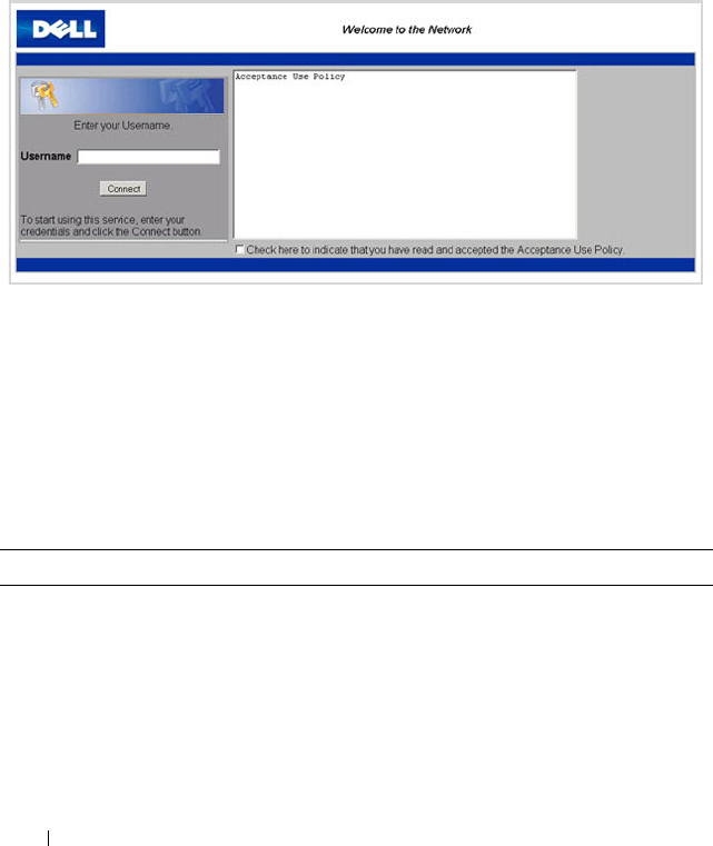
548 Configuring Port and System Security
Default Captive Portal Behavior and Settings
Captive Portal is disabled by default. If you enable Captive Portal, no
interfaces are associated with the default Captive Portal. After you associate
an interface with the Captive Portal and globally enable the Captive Portal
feature, a user who connects to the switch through that interface is presented
with the Captive Portal Welcome screen shown in Figure 19-15.
Figure 19-15. Default Captive Portal Welcome Screen
The user types a name in the Username field, selects the Acceptance Use
Policy check box, and clicks Connect to gain network access. By default, the
user does not need to be defined in a database or enter a password to access
the network because the default verification mode is Guest. Note that
duplicate Username entries can exist in this mode because the client IP and
MAC addresses are obtained for identification.
Table 19-4 shows the default values for the Captive Portal feature.
Table 19-4. Default Captive Portal Values
Feature Value
Global Captive Portal Operational
Status
Disabled
Additional HTTP or HTTPS Ports Disabled
Captive Portal can be configured to use an
additional HTTP and/or HTTPS port (in
support of Proxy networks).

Configuring Port and System Security 549
Authentication Timeout 300 seconds
Configured Captive Portals 1
Captive Portal Name Default
Protocol Mode HTTP
Verification Mode Guest
URL Redirect Mode Off
User Group 1-Default
Session Timeout 86400 seconds
Local Users None configured
Interface associations None
Interface status Not blocked
If the Captive Portal is blocked, users cannot
gain access to the network through the
Captive Portal. Use this function to
temporarily protect the network during
unexpected events, such as denial of service
attacks.
Supported Captive Portal users 1024
Supported local users 128
Supported Captive Portals 10
Table 19-4. Default Captive Portal Values
Feature Value
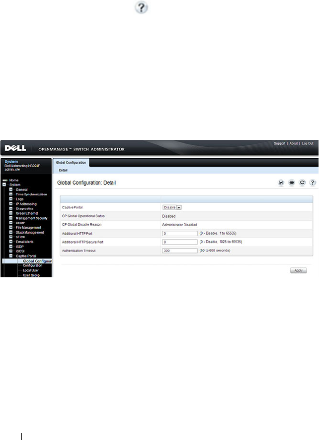
550 Configuring Port and System Security
Configuring the Captive Portal (Web)
This section provides information about the OpenManage Switch
Administrator pages for configuring and monitoring Captive Portal settings
on a Dell Networking N2000, N3000, and N4000 series switches. For details
about the fields on a page, click at the top of the page.
Captive Portal Global Configuration
Use the Captive Portal Global Configuration page to control the
administrative state of the Captive Portal feature and configure global
settings that affect all captive portals configured on the switch.
To display the Captive Portal Global Configuration page, click System
→
Captive Portal
→
Global Configuration.
Figure 19-16. Captive Portal Global Configuration
Captive Portal Configuration
Use the Captive Portal Configuration page to view summary information
about captive portals on the system, add a captive portal, and configure
existing captive portals.
The switch supports 10 Captive Portal configurations. Captive Portal
configuration 1 is created by default and cannot be deleted. Each captive
portal configuration can have unique guest or group access modes and a
customized acceptance use policy that displays when the client connects.

Configuring Port and System Security 551
To display the Captive Portal Configuration page, click System
→
Captive
Portal
→
Configuration.
Figure 19-17. Captive Portal Configuration
From the Captive Portal Configuration page, click Add to create a new
Captive Portal instance.
Figure 19-18. Add Captive Portal Configuration

552 Configuring Port and System Security
From the Captive Portal Configuration page, click Summary to view
summary information about the Captive Portal instances configured on the
switch.
Figure 19-19. Captive Portal Summary
Customizing a Captive Portal
The procedures in this section customize the pages that the user sees when he
or she attempts to connect to (and log off of) a network through the captive
portal. These procedures configure the English version of the Default captive
portal.
To configure the switch:
1
From the
Captive Portal Configuration
page click the
(English)
tab.The
settings for the
Authentication Page
display, and the links to the Captive
Portal customization appear.
2
Click
Download Image
to download one or more custom images to the
switch. You can use a downloaded custom image for the branding logo
(default: Dell logo) on the Authentication Page and Logout Success page,
the account image (default: blue banner with keys) on the Authentication
Page, and the background image (default: blank) on the Logout Success
Page.
NOTE: The image to download must be accessible from your local system.
The image should be 5 KB max, 200x200 pixels, GIF or JPG format.
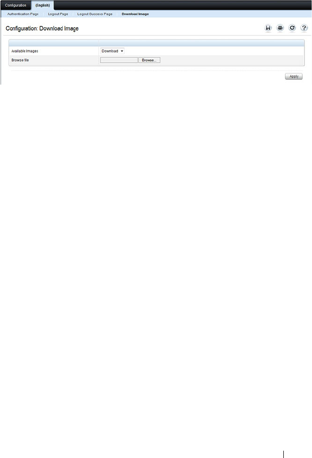
Configuring Port and System Security 553
Figure 19-20. Captive Portal Download Image Page
3
Make sure Download is selected in the
Available Images
menu, and click
Browse
.
4
Browse to the directory where the image to be downloaded is located and
select the image.
5
Click
Apply
to download the selected file to the switch.
6
To customize the Authentication Page, which is the page that a user sees
upon attempting to connect to the network, click the
Authentication Page
link.
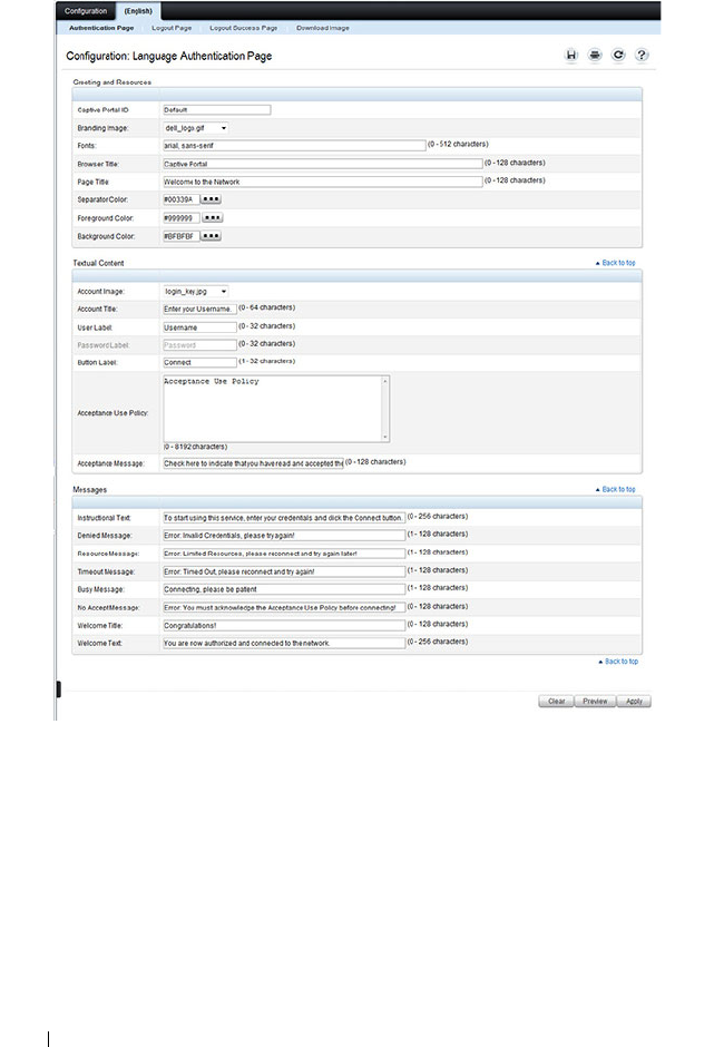
554 Configuring Port and System Security
Figure 19-21. Captive Portal Authentication Page
7
Select the branding image to use and customize other page components
such as the font for all text the page displays, the page title, and the
acceptance use policy.
8
Click
Apply
to save the settings to the running configuration or click
Preview
to view what the user will see. To return to the default views, click
Clear
.
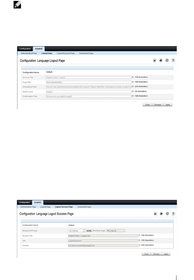
Configuring Port and System Security 555
9
Click the
Logout Page
link to configure the page that contains the logout
window.
Figure 19-22. Captive Portal Logout Page
10
Customize the look and feel of the Logout Page, such as the page title and
logout instructions.
11
Click
Apply
to save the settings to the running configuration or click
Preview
to view what the user will see. To return to the default views, click
Clear
.
12
Click the
Logout Success Page
link to configure the page that contains the
logout window. A user is required to logout only if the User Logout Mode
is selected on the
Configuration
page.
Figure 19-23. Captive Portal Logout Success Page
NOTE: You can configure the Logout Page settings only if the User Logout
Mode is selected on the Configuration page. The User Logout Mode allows
an authenticated client to deauthenticate from the network.

556 Configuring Port and System Security
13
Customize the look and feel of the Logout Page, such as the background
image and successful logout message.
14
Click
Apply
to save the settings to the running configuration or click
Preview
to view what the user will see. To return to the default views, click
Clear
.
Local User
You can configure a portal to accommodate guest users and authorized users.
Guest users do not have assigned user names and passwords. Authorized users
provide a valid user name and password that must first be validated against a
local database or RADIUS server. Authorized users can gain network access
once the switch confirms the user’s credentials.
By default, each Captive Portal instance contains the default group. The
default group can be renamed, or a different group can be created and
assigned to each Captive Portal instance. A Captive Portal instance can be
associated to one user group only. A user, however, can be assigned to multiple
groups.
The Local User page allows you to add authorized users to the local database,
which can contain up to 128 user entries. You can also add and delete users
from the local database from the Local User page.
To display the Local User page, click System
→
Captive Portal
→
Local User.
Figure 19-24 shows the Local User page after a user has been added. If no
users have been added to the switch, many of the fields do not display on the
screen.
NOTE: Multiple user groups can be selected by holding the CTRL key down while
clicking the desired groups.
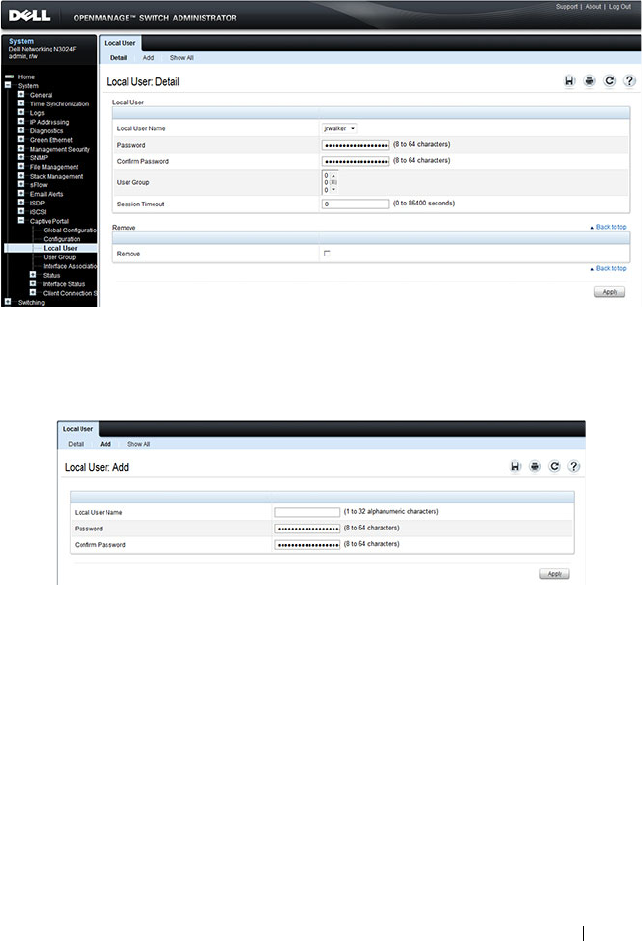
Configuring Port and System Security 557
Figure 19-24. Local User Configuration
From the Local User page, click Add to add a new user to the local database.
Figure 19-25. Add Local User
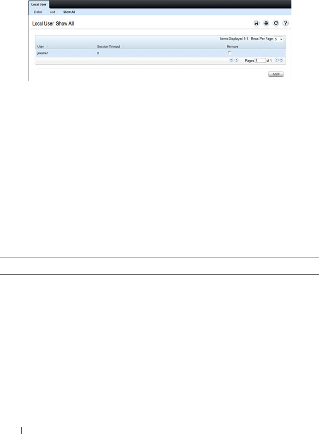
558 Configuring Port and System Security
From the Local User page, click Show All to view summary information
about the local users configured in the local database.
Figure 19-26. Captive Portal Local User Summary
To delete a configured user from the database, select the Remove check box
associated with the user and click Apply.
Configuring Users in a Remote RADIUS Server
You can use a remote RADIUS server client authorization. You must add all
users to the RADIUS server. The local database does not share any
information with the remote RADIUS database.
Table 19-5 indicates the RADIUS attributes you use to configure authorized
captive portal clients. The table indicates both RADIUS attributes and
vendor-specific attributes (VSA). VSAs are denoted in the Attribute column
and are comma delimited (vendor ID, attribute ID).
Table 19-5. Captive Portal User RADIUS Attributes
Attribute Number Description Range Usage Default
User-Name 1 User name to be
authorized
1-32
characters
Required None
User-Password 2 User password 8-64
characters
Required None

Configuring Port and System Security 559
User Group
You can assign Local Users to User Groups that you create. If the Verification
Mode is Local or RADIUS, you assign a User Group to a Captive Portal
Configuration. All users who belong to the group are permitted to access the
network through this portal. The User Group list is the same for all Captive
Portal configurations on the switch.
To display the User Group page, click System
→
Captive Portal
→
User
Group.
Session-Timeout 27 Logout once
session timeout is
reached (seconds).
If the attribute is 0
or not present
then use the value
configured for the
captive portal.
Integer
(seconds)
Optional 0
Dell-Captive-
Portal-Groups
6231,
127
A comma-
delimited list of
group names that
correspond to the
configured CP
instance
configurations.
String Optional None. The
default
group is
used if not
defined here
Table 19-5. Captive Portal User RADIUS Attributes
Attribute Number Description Range Usage Default
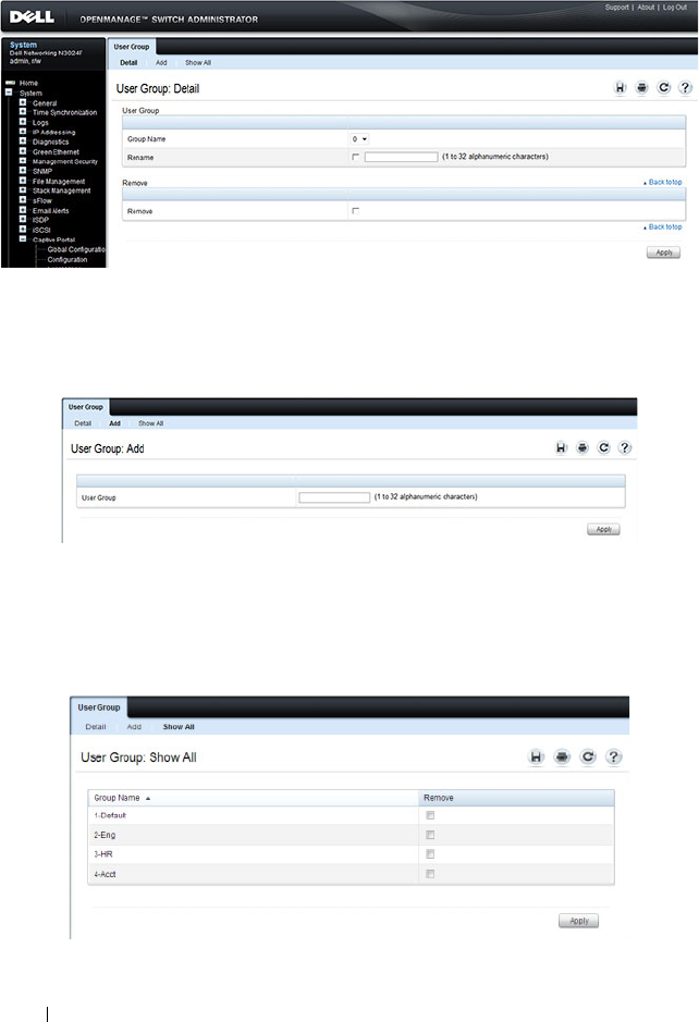
560 Configuring Port and System Security
Figure 19-27. User Group
From the User Group page, click Add to configure a new user group.
Figure 19-28. Add User Group
From the User Group page, click Show All to view summary information
about the user groups configured on the switch.
Figure 19-29. Captive Portal User Group Summary
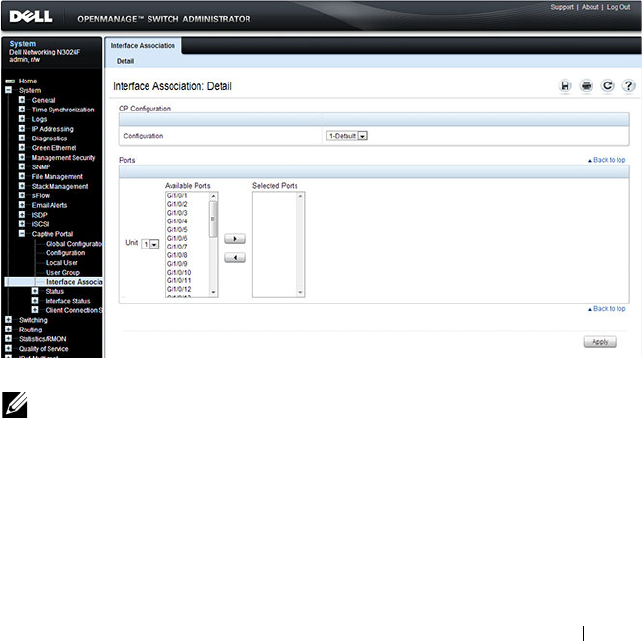
Configuring Port and System Security 561
To delete a configured group, select the Remove check box associated with
the group and click Apply.
Interface Association
From the Interface Association page, you can associate a configured captive
portal with specific interfaces. The captive portal feature only runs on the
interfaces that you specify. A captive portal can have multiple interfaces
associated with it, but an interface can be associated to only one Captive
Portal at a time.
To display the Interface Association page, click System
→
Captive Portal
→
Interface Association.
Figure 19-30. Captive Portal Interface Association
NOTE: When you associate an interface with a Captive Portal, the interface is
disabled in the Interface List. Each interface can be associated with only one
Captive Portal at a time.

562 Configuring Port and System Security
Captive Portal Global Status
The Captive Portal Global Status page contains a variety of information
about the Captive Portal feature. From the Captive Portal Global Status
page, you can access information about the Captive Portal activity and
interfaces.
To display the Global Status page, click System
→
Captive Portal
→
Status
→
Global Status.
Figure 19-31. Captive Portal Global Status
Captive Portal Activation and Activity Status
The Captive Portal Activation and Activity Status page provides information
about each Captive Portal configured on the switch.
The Captive Portal Activation and Activity Status page has a drop-down
menu that contains all captive portals configured on the switch. When you
select a captive portal, the activation and activity status for that portal
displays.
To display the Activation and Activity Status page, click System
→
Captive
Portal
→
Status
→
Activation and Activity Status.
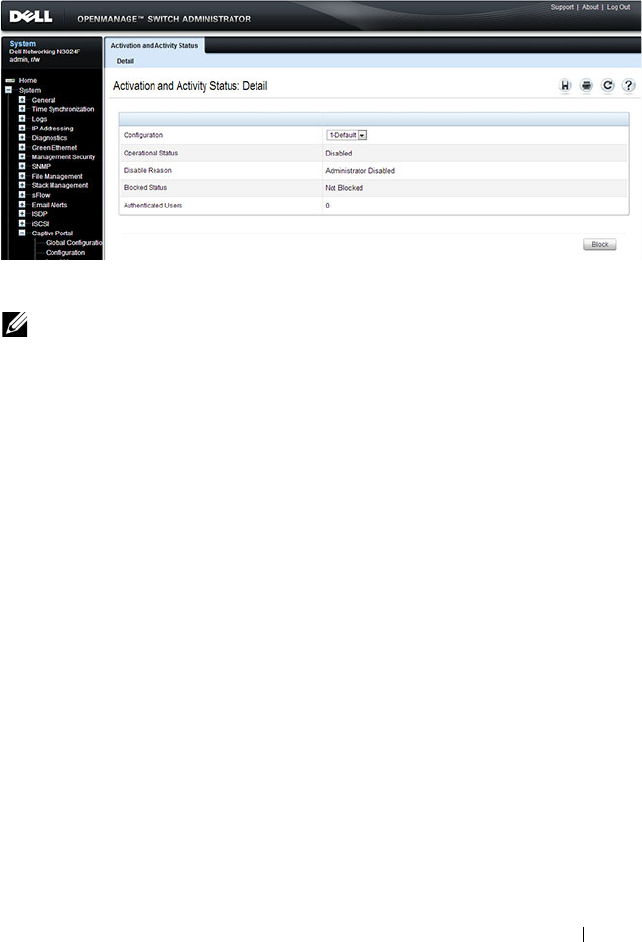
Configuring Port and System Security 563
Figure 19-32. Captive Portal Activation and Activity Status
Interface Activation Status
The Interface Activation Status page shows information for every interface
assigned to a captive portal instance.
To display the Interface Activation Status page, click System
→
Captive
Portal
→
Interface Status
→
Interface Activation Status.
NOTE: Use the Block and Unblock buttons to control the blocked status. If the
Captive Portal is blocked, users cannot gain access to the network through the
Captive Portal. Use this function to temporarily protect the network during
unexpected events, such as denial of service attacks.
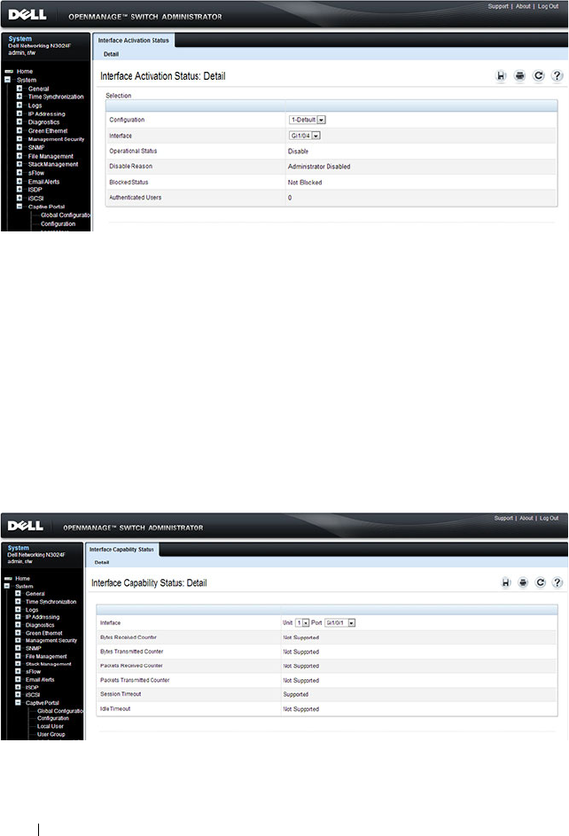
564 Configuring Port and System Security
Figure 19-33. Interface Activation Status
Interface Capability Status
The Interface Capability Status page contains information about interfaces
that can have CPs associated with them. The page also contains status
information for various capabilities. Specifically, this page indicates what
services are provided through the Captive Portal to clients connected on this
interface. The list of services is determined by the interface capabilities.
To display the Interface Capability Status page, click System
→
Captive
Portal
→
Interface Status
→
Interface Capability Status.
Figure 19-34. Interface Capability Status
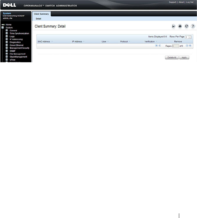
Configuring Port and System Security 565
Client Summary
Use the Client Summary page to view summary information about all
authenticated clients that are connected through the captive portal. From
this page, you can manually force the captive portal to disconnect one or
more authenticated clients. The list of clients is sorted by client MAC
address.
To display the Client Summary page, click System
→
Captive Portal
→
Client Connection Status
→
Client Summary.
Figure 19-35. Client Summary
To force the captive portal to disconnect an authenticated client, select the
Remove check box next to the client MAC address and click Apply. To
disconnect all clients from all captive portals, click Delete All.
Client Detail
The Client Detail page shows detailed information about each client
connected to the network through a captive portal.
To display the Client Detail page, click System
→
Captive Portal
→
Client
Connection Status
→
Client Detail.
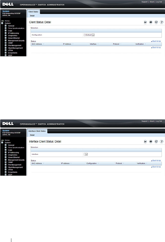
566 Configuring Port and System Security
Figure 19-36. Client Detail
Captive Portal Interface Client Status
Use the Interface Client Status page to view clients that are authenticated to
a specific interface.
To display the Interface Client Status page, click System
→
Captive
Portal
→
Client Connection Status
→
Interface Client Status.
Figure 19-37. Interface - Client Status
Captive Portal Client Status
Use the Client Status page to view clients that are authenticated to a specific
Captive Portal configuration.
To display the Client Status page, click System
→
Captive Portal
→
Client
Connection Status
→
Client Status.
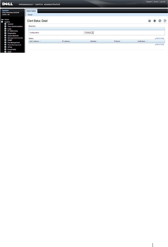
Configuring Port and System Security 567
Figure 19-38. Captive Portal - Client Status

568 Configuring Port and System Security
Configuring Captive Portal (CLI)
This section provides information about the commands you use to create and
configure Captive Portal settings. For more information about the
commands, see the
Dell Networking N2000, N3000, and N4000 Series
Switches CLI Reference Guide
at support.dell.com/manuals.
Configuring Global Captive Portal Settings
Beginning in Privileged EXEC mode, use the following commands to
configure global Captive Portal settings.
Command Purpose
configure Enter global configuration mode.
captive-portal Enter Captive Portal mode.
http port
port-num
(Optional) Configure an additional HTTP port for
Captive Portal to monitor. Use this command on networks
that use an HTTP proxy server.
port-num
— The port number to monitor (Range:
1–65535, excluding ports 80, 443, and the configured
switch management port).
https port
port-num
(Optional) Configure an additional HTTPS port for
Captive Portal to monitor. Use this command on networks
that use an HTTPS proxy server.
port-num
— The port number to monitor Range:
1–65535, excluding ports 80, 443, and the configured
switch management port).
authentication timeout
timeout
(Optional) Configure the number of seconds the user has
to enter valid credentials into the verification page. If the
user exceeds the configured timeout, the verification page
needs to be served again in order for the client to gain
access to the network.
timeout
— The authentication timeout (Range: 60–600
seconds).
enable Globally enable the Captive Portal feature.

Configuring Port and System Security 569
Creating and Configuring a Captive Portal
Beginning in Privileged EXEC mode, use the following commands to create a
Captive Portal instance and configure its settings.
CTRL + Z Exit to Privileged EXEC mode.
show captive-portal
[status]
View the Captive Portal administrative and operational
status. Use the status keyword to view additional global
Captive Portal information and summary information
about all configured Captive Portal instances.
Command Purpose
configure Enter global configuration mode.
captive-portal Enter Captive Portal mode.
configuration
cp-id
Enter the captive portal instance mode
cp-id
— The Captive Portal instance (Range: 1–10). The
Captive Portal configuration identified by CP ID 1 is the
default CP configuration.
name
string
Add a name to the Captive Portal instance.
string
— CP configuration name (Range: 1–32 characters).
protocol {http | https} Specify whether to use HTTP or HTTPs during the
Captive Portal user verification process.
verification {guest |
local | radius}
Specify how to process user credentials the user enters on
the verification page.
• guest — Allows access for unauthenticated users (users
that do not have assigned user names and passwords).
• local — Authenticates users against a local user database.
• radius — Authenticates users against a remote RADIUS
database.
radius-auth-server
name
Specify the name of the RADIUS server to use for
RADIUS verification. Use the commands described in
"Using RADIUS Servers to Control Management Access"
on page 232 to configure RADIUS server settings for the
switch.
Command Purpose

570 Configuring Port and System Security
user-logout (Optional) Enable user logout mode to allow an
authenticated client to deauthenticate from the network.
If this option is clear or the user does not specifically
request logout, the client connection status remains
authenticated until the CP deauthenticates the user, for
example by reaching the idle timeout or session timeout
values.
redirect (Optional) Enable the redirect mode for a Captive Portal
configuration so that the user is redirected to a specific
Web page after the verification or authentication process.
When the redirect mode is not enabled, the user sees the
Captive Portal welcome page after the verification or
authentication process.
redirect-url
url
(Optional) Specify the web page that the users sees after
successful verification or authentication through the
Captive Portal.
url
— The URL for redirection (Range: 1–512 characters).
group
group-number
(For Local and RADIUS verification) Configure the group
number associated with this Captive Portal configuration.
By default, only the default group exists. To assign a
different user group to the Captive Portal instance, you
must first configure the group.
group-number
— The number of the group to associate
with this configuration (Range: 1–10)
session-timeout
timeout
(Optional) Enter the number of seconds to wait before
terminating a session. A user is logged out once the session
timeout is reached. You can also set the session timeout for
each user if the Captive Portal requires authentication.
timeout
— Session timeout. 0 indicates timeout not
enforced (Range: 0–86400 seconds)
interface
interface
Associate an interface with this Captive Portal. (
The
interface
variable includes the interface type and
number, for example tengigabitethernet 1/0/3.
enable Enable the Captive Portal instance.
Command Purpose

Configuring Port and System Security 571
Configuring Captive Portal Groups and Users
Beginning in Privileged EXEC mode, use the following commands to create a
Captive Portal group. You can use the default group, or you can create a new
group.
block (Optional) Block all traffic for a Captive Portal
configuration. If the Captive Portal is blocked, users
cannot gain access to the network through the Captive
Portal. Use this function to temporarily protect the
network during unexpected events, such as denial of
service attacks.
CTRL + Z Exit to Privileged EXEC mode.
show captive-portal
configuration
cp-id
[status | interface]
View summary information about a Captive Portal
instance.
•
cp-id
— The Captive Portal instance (Range: 1–10).
•
status
— View additional information about the Captive
Portal instance.
• interface — View information about the interface(s)
associated with the specified Captive Portal.
show captive-portal
interface configuration
cp-id
status
View information about the interfaces associated with the
specified Captive Portal instance.
cp-id
— The Captive Portal instance (Range: 1–10).
NOTE: To return the default Captive Portal instance to its default values, use the
clear command in the Captive Portal Instance mode. You must also use the no
interface
interface
command to remove any associated interfaces from the
instance.
Command Purpose
configure Enter global configuration mode.
captive-portal Enter Captive Portal mode.
Command Purpose

572 Configuring Port and System Security
user group
group-id
[name
name
]
Configure a group. Each Captive Portal that requires
authentication has a group associated with it. Only the
users who are members of that group can be authenticated
if they connect to the Captive Portal.
•
group-id
— Group ID (Range: 1–10).
•
name
— Group name (Range: 1–32 characters).
user
user-id
name
name
Create a new user for the local user authentication
database.
•
user-id
—User ID (Range: 1–128).
•
name
—user name (Range: 1–32 characters).
user
user-id
password
password
Configure the password for the specified user.
•
user-id
—User ID (Range: 1–128).
•
password
—User password (Range: 8–64 characters).
user
user-id
group
group-
id
Associate a group with a Captive Portal user. A user can be
associated with more than one group.
•
user-id
— User ID (Range: 1–128).
•
group-id
— Group ID (Range: 1–10).
user
user-id
session-
timeout
timeout
Enter the number of seconds to wait before terminating a
session for the specified user. The user is logged out once
the session timeout is reached.
•
user-id
— User ID (Range: 1–128).
•
timeout
— Session timeout. 0 indicates timeout not
enforced (Range: 0–86400 seconds)
user group
group-id
moveusers
new-group-id
(Optional) Move all of the users in a group to a different
group. This command removes the users from the group
specified by
group-id
.
•
group-id
— Group ID (Range: 1–10).
•
new-group-id
— Group ID (Range: 1–10).
CTRL + Z Exit to Privileged EXEC mode.
show captive-portal user
[
user-id
]
View summary information about all users configured in
the local database. Specify the user ID to view additional
information about a user.
user-id
— User ID (Range: 1–128).
Command Purpose

Configuring Port and System Security 573
Managing Captive Portal Clients
The commands in this section are all executed in Privileged EXEC mode. Use
the following commands to view and manage clients that are connected to a
Captive Portal.
clear captive portal users (Optional) Delete all captive portal user entries from the
local database.
Command Purpose
show captive-portal
configuration [
cp-id
]
client status
Display information about the clients authenticated to all
Captive Portal configurations or a to specific
configuration.
cp-id
— The Captive Portal instance (Range: 1–10).
show captive-portal
interface
interface
client
status
Display information about clients authenticated on all
interfaces or no a specific interface.
interface
— Specific Ethernet interface, such as gi1/0/8.
show captive-portal
client [
macaddr
] status
Display client connection details or a connection summary
for connected Captive Portal users.
macaddr
— The MAC address of the client.
captive-portal client
deauthenticate
macaddr
Deauthenticate a specific captive portal client.
macaddr
— The MAC address of the client.
Command Purpose
574 Configuring Port and System Security
Captive Portal Configuration Example
The manager of a resort and conference center needs to provide wired
Internet access to each guest room at the resort and in each conference room.
Due to legal reasons, visitors and guests must agree to the resort’s acceptable
use policy to gain network access. Additionally, network access from the
conference rooms must be authenticated. The person who rents the
conference room space receives a list username and password combinations
upon arrival. Hotel employees have their own Captive Portal.
The network administrator for the resort and conference center decides to
configure the three Captive Portals Table 19-6 describes.
Configuration Overview
The following steps provide an overview of the process you use to configure
the Captive Portal feature.
To configure the switch:
1.
If you plan to use a RADIUS server for authentication, configure the
RADIUS server settings on the switch.
2.
If authentication is required, configure the user groups to associate with
each Captive Portal.
3.
Create (add) the Captive Portals.
Table 19-6. Captive Portal Instances
Captive Portal Name Description
Guest Free Internet access is provided in each guest room, but
guests must enter a name and agree to the acceptable use
policy before they can gain access. The manager wants guests
to be redirected to the resort’s home web page upon
successful verification. No logout is required.
Conference Because physical access to the conference rooms is less secure
than access to each guest room, the manager wants to ensure
that people who connect to the network through a port in a
conference room are authenticated. The Conference Captive
Portal uses the local database for authentication.
Employee To gain network access, resort employees must enter a
username and password that is stored on a RADIUS server.

Configuring Port and System Security 575
4.
Configure the Captive Portal settings for each Captive Portal, such as the
verification mode.
5.
Associate interfaces with the Captive Portal instances.
6.
Download the branding images, such as the company logo, to the switch.
The images you download must be accessible from the switch, either on
the system you use to manage the switch or on a server that is on the same
network as the switch.
7.
Customize the authentication, logout, and logout success web pages that a
Captive Portal user will see.
Dell recommends that you use Use Dell OpenManage Administrator to
customize the Captive Portal authentication, logout, and logout success
pages. A
Preview
button is available to allow you to see the pages that a
Captive Portal user will see.
8.
If you use the local database for user authentication, configure the users on
the switch.
9.
If you use a RADIUS server for authentication, add the users to the
database on the RADIUS server.
10.
Associate interfaces with the Captive Portal instances.
11.
Globally enable Captive Portal.
Detailed Configuration Procedures
Use the following steps to perform the Captive Portal configuration:
1.
Configure the RADIUS server information on the switch.
In this example, the RADIUS server IP address is 192.168.2.188, and the
RADIUS server name is luxury-radius.
console#configure
console(config)#radius-server host 192.168.12.182
console(Config-auth-radius)#name luxury-radius
console(Config-auth-radius)#exit
2.
Configure the Captive Portal groups.
NOTE: You must use the web interface to download images.

576 Configuring Port and System Security
console(config)#captive-portal
console(config-CP)#user group 2 name Conference
console(config-CP)#user group 3 name Employee
console(config-CP)#exit
3.
Configure the Guest Captive Portal.
console(config)#captive-portal
console(config-CP)#configuration 2
console(config-CP 2)#name Guest
console(config-CP 2)#redirect
console(config-CP 2)#redirect-url
http://www.luxuryresorturl.com
console(config-CP 2)#interface te1/0/1
console(config-CP 2)#interface te1/0/2
...
console(config-CP 2)#interface te1/0/4
console(config-CP 2)#exit
4.
Configure the Conference Captive Portal.
console(config-CP)#configuration 3
console(config-CP 3)#name Conference
console(config-CP 3)#verification local
console(config-CP 3)#group 2
console(config-CP 4)#interface te1/0/825
...
console(config-CP 4)#interface te1/0/1533
console(config-CP 3)#exit
5.
Configure the Employee Captive Portal.
console(config-CP)#configuration 4
console(config-CP 4)#name Employee
console(config-CP 4)#verification radius
console(config-CP 4)#group 3
console(config-CP 4)#interface te1/0/1834
...
console(config-CP 4)#interface te1/0/2240
console(config-CP 4)#exit

Configuring Port and System Security 577
6.
Use the web interface to customize the Captive Portal pages that are
presented to users when they attempt to connect to the network.
7.
Add the Conference users to the local database.
console(config-CP)#user 1 name EaglesNest1
console(config-CP)#user 1 password
Enter password (8 to 64 characters): *********
Re-enter password: *********
console(config-CP)#user 1 group 2
Continue entering username and password combinations to populate the
local database.
8.
Add the User-Name, User-Password, Session-Timeout, and Dell-Captive-
Portal-Groups attributes for each employee to the database on the
RADIUS server.
9.
Globally enable the Captive Portal.
console(config-CP)#enable
NOTE: Captive Portal page customization is supported only through the Web
interface. For information about customizing the Captive Portal pages, see
"Customizing a Captive Portal" on page 552.

578 Configuring Port and System Security
Authentication Manager
Overview
The Authentication Manager supports the hierarchical configuration of host
authentication methods on an interface. Dell switches support the following
host authentication methods:
• IEEE 802.1x
• MAC Authentication Bypass
• Captive portal
Using the Authentication Manager, the administrator can configure an
authentication method list on a per-port basis. Authentication can be enabled
or disabled. If authentication is disabled, then no authentication method is
applied and the port is provided with open access. The default behavior is
that authentication is disabled for all ports.
The configured authentication methods are attempted in the configured
order. If an authentication method times out, then the next configured
method is attempted. If an authentication method fails, then the next
method is not attempted and authentication begins again from the first
method. If all the methods fail, then the Authentication Manager starts a
timer for reauthentication. Failure in this context means that host
authentication was attempted and the host was unable to successfully
authenticate. At the expiry of the timer, the Authentication Manager starts
the authentication process again from the first method in the list.
The Authentication Manager supports configuring a priority for each
authentication method on a port. The authentication priority allows a higher
priority method (not currently running) to interrupt an authentication in
progress with a lower-priority method. If a client is already authenticated, an
interrupt from a higher-priority method can cause a client previously
authenticated using a lower priority method to reauthenticate.
By default, Dell switches are configured with a method list that contains the
methods (in order) Dot1x, MAB, and captive portal (web-auth) as the default
methods for all the ports. Dell switches restrict the configuration such that no
method is allowed to follow the captive portal method, if configured.

Configuring Port and System Security 579
When a client is connected to a port, the switch tries to authenticate the
user/client using the methods in configuration order. If any authentication
method times out (an error), then the next authentication method is tried. If
all authentication methods configured for the port error out, the switch starts
a timer whose value is equal to the authentication restart timer. At the expiry
of the timer, the switch restarts the authentication process from the first
method. This timer starts only when all of the authentication methods error
out.
The authentication manager controls only the order in which the
authentication methods are executed. The switch administrator is responsible
for implementing the required configuration for the respective methods to
authenticate successfully.
Authentication Restart
Authentication restarts from the first configured method on any of the
following events:
• Link flap
• Authentication fails for all configured methods
• Authentication priority (802.1X packet received when a lower priority
method is active)
802.1X Interaction
By default, 802.1X drops all traffic prior to successful 802.1X (or MAB)
authentication. If captive portal is configured as a method, authentication
allows certain traffic types, such as DHCP or DNS, access to the network
during the captive portal method invocation.
Authentication Priority
The default authentication priority of a method is equivalent to its position
in the order of the authentication list. If authentication method priorities are
not configured, then the relative priorities (first is highest) are in the same
order as that of the per-port based authentication list.

580 Configuring Port and System Security
Authentication priority allows a higher-priority method (not currently
running) to interrupt an authentication in progress with a lower-priority
method. Alternatively, if the client is already authenticated, an interrupt from
a higher-priority method can cause a client, which was previously
authenticated using a lower-priority method, to reauthenticate.
For example, if a client is already authenticated using a method other than
802.1X (MAB or captive portal) and 802.1X has higher priority than the
authenticated method, and if an 802.1X frame is received, then the existing
authenticated client is removed and the authentication process begins again
from the first method in the order. If 802.1X has a lower priority than the
authenticated method, then the client is not removed and the 802.1X frames
are ignored.
If administrator changes the priority of the methods, then all the users who
are authenticated using a lower-priority method are forced to reauthenticate.
If an authentication session is in progress and the administrator changes the
order of the authentication methods, then the configuration will take effect
for the next session onwards.
Configuration Example—802.1X and MAB
In this scenario, the authentication manager selects the first authentication
method, 802.1X. If authentication using 802.1X is successful, then the client
is allowed network access. If authentication using 802.1X errors out, then
authentication manager selects the next authentication method: MAB. If
authentication using MAB returns an error, then the port is unauthorized.
The authentication manager will start a timer to re-authenticate the client.
At the expiry of the timer, the authentication manager restarts authentication
by selecting the 802.1X method.
console#configure
console(config)#radius-server host 10.10.10.10
console(Config-radius)#name BigRadius
console(Config-radius)#primary
console(Config-radius)#usage 802.1x
console(Config-radius)#exit
console(config)#radius-server key thatsyoursecret-keepit-keepit
console(config)#authentication enable
console(config)#aaa authentication dot1x default radius
console(config)#dot1x system-auth-control
console(config)#interface te1/0/4
console(config-if-Te1/0/4)#authentication order dot1x mab

Configuring Port and System Security 581
console(config-if-Te1/0/4)#dot1x reauthentication
console(config-if-Te1/0/4)#dot1x port-control mac-based
console(config-if-Te1/0/4)#dot1x mac-auth-bypass
console(config-if-Te1/0/4)#exit
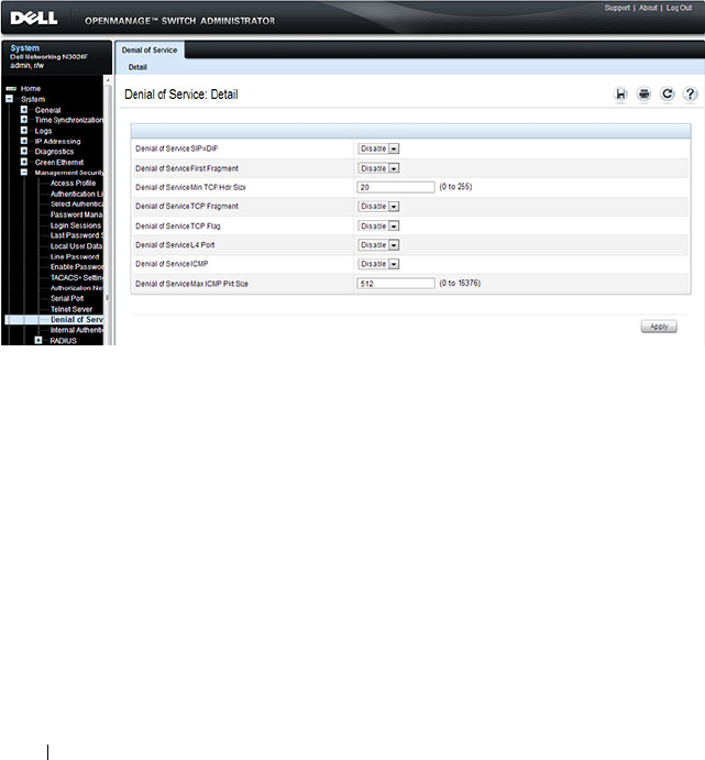
582 Configuring Port and System Security
Denial of Service
Denial of Service (DoS) refers to the exploitation of a variety of
vulnerabilities which would interrupt the service of a host or make a network
unstable. Use the Denial of Service page to configure settings to help prevent
DoS attacks.
DoS protection is disabled by default.
To display the Denial of Service page, click System
→
Management Security
→
Denial of Service in the navigation panel.
Figure 19-39. Denial of Service

Configuring Access Control Lists 583
20
Configuring Access Control Lists
This chapter describes how to configure Access Control Lists (ACLs),
including IPv4, IPv6, and MAC ACLs. This chapter also describes how to
configure time ranges that can be applied to any of the ACL types.
The topics covered in this chapter include:
• ACL Overview
• ACL Configuration Details
• Policy Based Routing
• Configuring ACLs (Web)
• Configuring ACLs (CLI)
• ACL Configuration Examples
ACL Overview
Access Control Lists (ACLs) are a collection of rules that provide security by
blocking selected packets from ingressing the switch. ACLs are implemented
in hardware and processed at line rate for the front-panel ports. A reduced
functionality set of ACLs is implemented in firmware for the OOB port.
ACLs can also provide traffic rate limiting and decide which types of traffic
are forwarded or blocked. ACLs can reside in a firewall router, a router
connecting two internal networks, or a Layer 3 switch, such as a
Dell
Networking N2000, N3000, and N4000 series switches
.
You can also create an ACL that limits access to the management interfaces
based on the connection method (for example, Telnet or HTTP) and/or the
source IP address.
The Dell Networking series switches support ACL configuration in both the
ingress and egress direction. Egress ACLs provide the capability to implement
security rules on the egress flows (traffic leaving a port) rather than the
ingress flows (traffic entering a port). Ingress and egress ACLs can be applied
to any physical port, port-channel (LAG), or VLAN routing port.

584 Configuring Access Control Lists
Depending on whether an ingress or egress ACL is applied to a port, when the
traffic enters (ingress) or leaves (egress) a port, the ACL compares the criteria
configured in its rules, in list order, to the fields in a packet or frame to check
for matching conditions. The ACL processes the traffic based on the actions
contained in the rules.
ACL rules are processed in list order, from the first to the last rule in the list.
If a matching rule is found, the rule action is taken and no subsequent rules in
the list are processed for that packet. Frequently matched rules should be
placed near or at the front of the list. A list must have at least one permit
entry or all traffic is denied (dropped).
Egress ACLs filter switched traffic only. Packets generated by the switch are
sent regardless of any egress ACL deny rules.
You can set up ACLs to control traffic at Layer 2, Layer 3, or Layer 4. MAC
ACLs operate on Layer 2. IP ACLs operate on Layers 3 and 4. Dell
Networking series switches
support both IPv4 and IPv6 ACLs.
What Are MAC ACLs?
MAC ACLs are Layer 2 ACLs. You can configure the rules to inspect the
following fields of a packet:
• Source MAC address
•Source MAC mask
• Destination MAC address
•Destination MAC mask
• VLAN ID
• Class of Service (CoS) (802.1p)
•EtherType
L2 ACLs can apply to one or more interfaces.
Multiple access lists can be applied to a single interface; sequence number
determines the order of execution.
NOTE: The last access group configured is terminated by an implicit deny all
rule, which drops any packet not matching a preceding rule.

Configuring Access Control Lists 585
MAC access list actions include CoS queue assignment, mirroring,
redirection to another port, and logging, as well as the usual permit and deny
actions.
What Are IP ACLs?
IP ACLs classify for Layers 3 and 4 on IPv4 or IPv6 traffic.
Each ACL is a set of up to 100 rules applied to inbound or outbound traffic.
IP ACLs support logging, redirect, mirroring, and drop. The following fields
may be specified in the permit or deny rules.
• Destination IP with wildcard mask
•Destination L4 port
• Every protocol or a specific protocol
•IP DSCP
• IP precedence
•IP TOS
•TCP flags
•Source IP with wildcard mask
• Source L4 port, with eq, ne, gt, and lt operators and ranges (IP/TCP/UDP
packets only)
• Destination layer 4 port, with eq, ne, gt, and lt operators and ranges
(IP/TCP/UDP packets only)
What Is the ACL Redirect Function?
The redirect function allows traffic that matches a permit rule to be
redirected to a specific physical port or LAG instead of processed on the
original port. A packet that is redirected does not go through the normal
forwarding process. It is sent to the redirect target port. The redirect function
and mirror function are mutually exclusive. In other words, you cannot
configure a given ACL rule with both mirror and redirect attributes.
What Is the ACL Mirror Function?
ACL mirroring provides the ability to mirror traffic that matches a permit
rule to a specific physical port or LAG. Mirroring is similar to the redirect
function, except that in flow-based mirroring a copy of the permitted traffic is

586 Configuring Access Control Lists
delivered to the mirror interface while the packet itself is forwarded normally
through the device. You cannot configure a given ACL rule with both mirror
and redirect attributes.
Using ACLs to mirror traffic is considered to be flow-based mirroring since
the traffic flow is defined by the ACL classification rules. This is in contrast to
port mirroring, where all traffic encountered on a specific interface is
replicated on another interface.
What Is ACL Logging
ACL Logging provides a means for counting the number of “hits” against an
ACL rule. When you configure ACL Logging, you augment the ACL deny
rule specification with a "log" parameter that enables hardware hit count
collection and reporting. The switch uses a fixed five minute logging interval,
at which time trap log entries are written for each ACL logging rule that
accumulated a non-zero hit count during that interval. You cannot configure
the logging interval.
What Are Time-Based ACLs?
The time-based ACL feature allows the switch to dynamically apply an
explicit ACL rule within an ACL for a predefined time interval by specifying a
time range on a per-rule basis within an ACL, so that the time restrictions are
imposed on the ACL rule.
With a time-based ACL, you can define when and for how long an individual
rule of an ACL is in effect. To apply a time to an ACL, first you define a
specific time interval and then apply it to an individual ACL rule so that it is
operational only during the specified time range, for example, during a
specified time period or on specified days of the week.
A time range can be absolute (specific time) or periodic (recurring). If an
absolute and periodic time range entry are defined within the same time
range, the periodic timer is active only when the absolute timer is active.
NOTE: Adding a conflicting periodic time range to an absolute time range will
cause the time range to become inactive. For example, consider an absolute time
range from 8:00 AM Tuesday March 1st 2011 to 10 PM Tuesday March 1st 2011.
Adding a periodic entry using the 'weekend' keyword will cause the time-range
to become inactive because Tuesdays are not on the weekend.

Configuring Access Control Lists 587
A named time range can contain up to 10 configured time ranges. Only one
absolute time range can be configured per time range. During the ACL
configuration, you can associate a configured time range with the ACL to
provide additional control over permitting or denying a user access to network
resources.
Benefits of using time-based ACLs include:
• Providing more control over permitting or denying a user access to
resources, such as an application (identified by an IP address/mask pair and
a port number).
• Providing control of logging messages. Individual ACL rules defined within
an ACL can be set to log traffic only at certain times of the day so you can
simply deny access without needing to analyze many logs generated during
peak hours.
What Are the ACL Limitations?
There are two hardware matching engines visible to the Dell switch
administrator: the ingress processor and the egress processor. Each of these
processors has different limits and actions. The ingress matching engine
processes packets on ingress to the switch and can apply actions such as
applying CoS processing, diverting to a different port, etc. The egress
matching engine processes packets after they are switched and queued for
egress and supports policies such as rewriting the DSCP or CoS values, as well
as the normal permit (forward) and deny (drop) actions.
ACLs operate by matching on specific fields within packets. Various match
conditions (operators) are supported (e.g., equal, less than, not equal, etc.),
along with masks that support selection of all or a portion of a field. Each field
to be matched is assigned to a matching engine (slice). A slice is defined by
an offset into the packet that is compared against a set of matching values
and masks along with an associated action (ACEs). Each Dell Networking
switch series supports a fixed number of slices and each slice supports a fixed
number of matching criteria (values and masks). Slices operate in parallel to
perform the configured matching operations. An ACL with a different offset
requires the use of a new hardware slice but multiple matching values can be
specified for a single slice (e.g., an IPv4 destination address with a 32-bit mask
is 192.168.21.1 or 192.168.12.3). Slices can also be joined together to match
widths larger than 32 bits or they can be concatenated to provide a larger
number of matching values with a single offset. In general, ACLs that match

588 Configuring Access Control Lists
on less than 32 bits will be expanded internally to match on 32 bits with a
variable mask. This allows other ACLs using the same offset to utilize the
same slice with potentially different masks and match values.
The user interface limits for ACLs are 1023 rules per access list and 100 access
lists. The switch automatically combines slices to operate in parallel over
greater field widths (e.g., IPv6 source address) or combines slices to supply
more match conditions (IPv4 destination address equal to multiple ranges of
addresses). In the case of a match condition specifying a 128-bit IPv6 address,
additional slices are assigned to operate in parallel on specific portions of the
address. This reduces the overall number of slices available to match on other
key fields. The switch attempts to assign slices to match conditions in an
optimal manner; however, combinations of match conditions can reduce the
maximum number of ACLs that can be configured to fewer than the
published limits. As an example, the smallest IPv6 QoS match will take 6
slices from the switch.
The N4000 switches support the following hardware limits:
• 2047 ingress rules and 1023 egress rules, for a total of 3072 rules.
• The hardware has 10 ingress slices and 4 egress slices, with 4 ingress slices
having a depth of 128 rules, and 6 ingress slices having a depth of 256 rules.
The egress slices have a depth of 256 rules.
The N3000 switches support the following hardware limits:
• 3072 ingress rules and 1024 egress rules, for a total of 4096 rules.
• The hardware has 14 ingress slices and 4 egress slices, with the 14 ingress
slices having a depth of 256 rules. The egress slices have a depth of 256
rules.
The N2000 switches support the following hardware limits:
• 1024 ingress rules and 512 egress rules, for a total of 1536 rules.
• The hardware has 14 ingress slices and 4 egress slices, with the 14 ingress
slices having a depth of 256 rules. The egress slices have a depth of 256
rules.
The software limits are shown in Table 20-1:

Configuring Access Control Lists 589
Please note the following additional limitations on ingress and egress ACLs:
• You can configure mirror or redirect attributes for a given ACL rule, but
not both.
•The
Dell Networking series switches
support a limited number of counter
resources, so it may not be possible to log every ACL rule. You can define
an ACL with any number of logging rules, but the number of rules that are
actually logged cannot be determined until the ACL is applied to an
interface. Furthermore, hardware counters that become available after an
ACL is applied are not retroactively assigned to rules that were unable to
be logged (the ACL must be disassociated from the interface and then re-
associated). Rules that are unable to be logged are still active in the ACL
for purposes of permitting or denying a matching packet. If console logging
is enabled and the severity is set to a numerically lower severity than the
console severity setting, a log entry may appear on the screen.
Table 20-1. ACL Software Limits
Limitation N2000 N3000 N4000
Maximum Number of ACLs (any
type)
100 100 100
Maximum Number Configurable
Rules per List
1023 1023 1023
Maximum ACL Rules per Interface
and Direction (IPv4/L2)
1024 ing/
512 egr
3072 ing/
1024 egr
2047 ing/
1023 egr
Maximum ACL Rules per Interface
and Direction (IPv6)
512 ing/
256 egr
1021 ing/
512 egr
1021 ing/
512 egr
Maximum ACL Rules (system-
wide)
2048 4096 3072
Maximum VLAN interfaces with
ACLs applied
24 24 24
Maximum ACL Logging Rules
(system-wide)
128 128 128

590 Configuring Access Control Lists
• The order of the rules is important: when a packet matches multiple rules,
the first rule takes precedence. Once a packet has matched a rule, the
corresponding action is taken and no further attempts to match the packet
are made. Also, once you define an ACL for a given port, all traffic not
specifically permitted by the ACL is denied access.
• Egress (out) ACLs only affect switched/routed traffic. They have no effect
on packets generated locally by the switch, e.g., LACPDUs or spanning
tree BPDUs.
• Ingress ACLs filter packets before they are processed by the switching
fabric. Egress ACLs filter packets after they have been processed by the
switching fabric.
• User-defined ingress ACLs are prioritized before system ACLs. User-
defined ingress ACLs that match control plane packets such as BPDUs
interfere with switch operation.
• Port ranges are not supported for egress ACLs for either IPv4 or IPv6 ACLs.
•The
fragments
and
routing
keywords are not supported for egress IPv6
ACLs. The
fragments
keywords is not supported on IPv4 egress ACLs.
• On the N4000 switches, the IPv6 ACL
routing
keyword is not supported
when any IPv6 address is specified. The
routing
keyword is not support for
IPv4 ACLs.
• On the N4000 switches, the IPv6 ACL
fragment
keyword matches only on
the first two IPv6 extension headers for the fragment header (next header
code 44). If the fragment header appears in the third or subsequent header,
it is not matched
• On the N2000 and N3000 switches, the IPv6 ACL
fragment
keyword
matches only on the first IPv6 extension header (next header code 44). If
the fragment header appears in the second or subsequent header, it is not
matched.
•The IPv6 ACL
routing
keyword matches only on the first IPv6 extension
header (next header code 43). If the fragment header appears in the
second or subsequent header, it is not matched.
NOTE: The actual number of ACLs and rules supported depends on the
resources consumed by other processes and configured features running on the
switch.

Configuring Access Control Lists 591
ACL Configuration Details
How Are ACLs Configured?
To configure ACLs, follow these steps:
1
Create a MAC ACL by specifying a name.
2
Create an IP ACL by specifying a number.
3
Add new rules to the ACL.
4
Configure the match criteria for the rules.
5
Apply the ACL to one or more interfaces.
Editing Access Lists
When editing access lists, new entries are added to the end of the list. There
is an implicit deny all statement at the end of every access-group that is not
shown and is not editable. To insert a rule in the middle of an ACL, you must
delete the list, and then add the rules again, in order, with the newly included
entry. One way to manage this process is to show the running config, copy the
access list to an editor, edit the list offline, delete the access list on the switch,
and then paste the updated access list back into the switch console.
Preventing False ACL Matches
Be sure to specify ACL access-list, permit, and deny rule criteria as fully as
possible to avoid false matches. This is especially important in networks with
protocols that have different frame or EtherType values. For example, L3
ACL rules that specify a TCP or UDP port value should also specify the TCP
or UDP protocol. MAC ACL rules that specify an EtherType value for the
frame should also specify a source or destination MAC address wherever
possible.
NOTE: When configuring access lists, complete checks are made only when the
access list is applied to an active interface. It is recommended that you configure
and test an access list on an active (up) interface prior to deploying it on links in
the production network. If an ACL is configured on an interface that is not up,
error messages regarding ACL resource allocation may be logged when the
interface is brought up.

592 Configuring Access Control Lists
In general, any rule that specifies matching on an upper-layer protocol field
should also include matching constraints for as many of the lower-layer as
where possible. For example, a rule to match packets directed to the well-
known UDP port number 22 (SSH) should also include matching constraints
on the IP protocol field (protocol=0x11 or UDP) and the source or
destination IP address. Table 20-2 lists commonly-used EtherTypes numbers:
Figure 20-3 lists commonly-used IP protocol numbers:
Table 20-2. Common EtherType Numbers
EtherType Protocol
0x0800 Internet Protocol version 4 (IPv4)
0x0806 Address Resolution Protocol (ARP)
0x0842 Wake-on LAN Packet
0x8035 Reverse Address Resolution Protocol (RARP)
0x8100 VLAN tagged frame (IEEE 802.1Q)
0x86DD Internet Protocol version 6 (IPv6)
0x8808 MAC Control
0x8809 Slow Protocols (IEEE 802.3)
0x8870 Jumbo frames
0x888E EAP over LAN (EAPOL – 802.1x)
0x88CC Link Layer Discovery Protocol
0x8906 Fibre Channel over Ethernet
0x9100 Q in Q
Table 20-3. Common IP Protocol Numbers
IP Protocol Number Protocol
0x00 IPv6 Hop-by-hop option
0x01 ICMP
0x02 IGMP
0x06 TCP

Configuring Access Control Lists 593
Using IP and MAC Address Masks
Masks are used with IP and MAC addresses to specify what should be
considered in the address for a match. Masks are expanded internally into a
bit mask and are applied bit-wise in the hardware even though they are
entered in decimal or hexadecimal format. Masks need not have contiguous 0
or 1 bits. A 0 bit value in the mask indicates that the address field in the
packet being compared must match the address bit exactly. A 1 value in the
mask indicates a wildcard or don't care value, i.e. the access bits are not
compared and match any possible value. For example, an IP address of 3.3.3.3
with a mask of 0.0.0.0 indicates that the ACL matches on all four bytes of the
IP address. Likewise, a MAC address of 68:94:23:AD:F3:18 with a mask of
00:00:00:00:00:ff indicates that the first five bytes must match (e.g.,
68:94:23:AD:F3) and the last byte may take on any value from 0x00 to 0xff
(0–255) and still be considered a match.
The following ACL equivalents are noted:
0x08 EGP
0x09 IGP
0x11 UDP
Address Mask Equivalent Address
0.0.0.0 255.255.255.255 any
x.x.x.x host x.x.x.x
0:0:0:0:0:0 ff:ff:ff:ff:ff:ff any
Table 20-3. Common IP Protocol Numbers (Continued)
IP Protocol Number Protocol

594 Configuring Access Control Lists
Policy Based Routing
Overview
In contemporary inter-networks, network administrators often need to
implement packet routing according to specific organizational policies. Policy
Based Routing (PBR) exactly fits this purpose. PBR provides a flexible
mechanism to implement solutions where organizational constraints dictate
that traffic be routed through specific network paths. PBR does not affect
route redistribution that occurs via routing protocols.
PBR is a true routing solution. The packet TTL is decremented in PBR-
routed packets. The destination MAC is rewritten in PBR routed packets.
ARP lookups are sent when required for unresolved next hop addresses. PBR
routed packets are routed via routing table lookups. Routes must exist in the
routing table for PBR next-hop and default next-hop rules.
Configuring PBR consists of installing a route-map with match and set
commands, and then applying the corresponding route-map to the interface.
IP routing must be enabled on the interfaces and globally.
PBR is applied to inbound traffic on IP routing interfaces. Enabling the
feature causes the router to analyze packets entering the interface using a
route-map. A VLAN can only have one associated route-map, but the
administrator can configure multiple route-map entries in the route-map
with different sequence numbers. Packets entering the interface are filtered
by a user-selected ACL. Packets that are allowed by the ACL are evaluated in
order of increasing sequence number until a viable routing destination is
found. Other actions may also be specified. If no action is executed, packets
are routed via normal routing table lookup.
ACLs present in a route-map’s match clauses inherit the ordering of the
containing route-map sequence number. Therefore, it is recommended that
ACLs used in route-map match clauses be independent of ACLs used in
access-groups in order to preserve access-group ordering.
A route-map rule may be configured as a permit or deny rule. If the rule is
marked as deny, traditional destination-based routing is performed on the
packet meeting the ACL match criteria. If the rule is marked as permit, and if
the packet meets the ACL match criteria, then the action specified by the set
commands in the route-map statement are evaluated. If no active route is
found in the route-map, the packet is forwarded using traditional destination-

Configuring Access Control Lists 595
based routing. If the network administrator instead wants to drop a packet
that does not match the specified criteria, a set statement must be configured
to route the packet to interface null0 as the last entry in the route-map.
Deny route-maps forward packets with matching ACL criteria using normal
route table lookups. If an associated ACL rule is marked as deny, traditional
destination-based routing is performed on the packet meeting the match
criteria. A set clause is required in a deny route map for it to be processed.
Route-maps may specify multiple packet attributes in match statements.
These attributes can be matched through a “match” clause based on the
length of the packet or a “match” clause linked with an ACL.
The following packet attributes are supported to classify L3 routed traffic for
PBR:
• MAC access list (match mac-list)
– Source MAC address
– 802.1p priority
• IP access list (match ip address)
– Source or destination IP address
– Source or destination TCP/UDP port
• L3 packet length in the IP header (match length)
The Policy Based Routing feature overrides the normal routing decisions
taken by the router and attempts to route the packet using the criteria in the
set clause:
• List of next hop IP addresses — The
set ip next-hop
command checks for
the next-hop address in the routing table, and if the next-hop address is
present and active in the routing table, then the policy routes the ACL
matching packets to the next hop. If the next hop is not present in the
routing table, the command uses the normal routing table to route the
packet. Non-matching packets are routed using the normal routing table.
The IP address must specify an adjacent next-hop router in the path
toward the destination to which the packets should be routed. The first
available IP address associated with a currently active routing entry is used
to route the packets. This type of rule takes priority over explicit routing
entries in the routing table, but not default routing entries.

596 Configuring Access Control Lists
• List of default next hop IP addresses — The
set ip default next-hop
command checks the list of destination IP addresses in the routing table
and, if there is no explicit route for the packet's destination address in the
routing table, the next-hop destinations in the rule are evaluated, and
packets are routed to the first available next hop. Packets that do not
match are routed using the routing table default. A default route in the
routing table is not considered an explicit route for an unknown
destination address. This type of rule takes priority over default entries in
the routing table but is processed after explicit routing table entries.
• IP precedence — Packets matching the criteria have their IP precedence
rewritten. The IP precedence value is the four ToS bits in the IP packet
header.
Limitations
Set Clause Required
Route-map deny/permit statements without “set” clauses are ignored.
No Implicit “deny all” Rule
When an access-group is applied to an interface, an implicit rule of “deny all”
is applied after the last access-group on the interface. When match rules in an
ACL associated with a permit route-map are successful, the packets are
considered as candidates to be routed according to the set clauses specified in
the route-map. If none of the permit rules match, then the packet is routed
by the standard L3 routing process. The implicit “deny all” rule is not
applicable to ACLs associated with “permit” route-maps.
Black Holes Possible
If the next hop specified by a policy based rule is not reachable, packets
matching the rule are routed using the routing table. If the routing table does
not supply a route to the destination, then the packets are lost. If a set
interface Null0 clause is present in the policy map, the packets are dropped.
The set interface null0 command can also be used to drop undesirable or
unwanted traffic, i.e., to create a black hole route.

Configuring Access Control Lists 597
Resource-Sharing Between ACLs and PBR
ACLs associated with a route-map and general ACLs share the same hardware
resources. If PBR consumes the maximum number of HW resources on an
interface or system-wide, general purpose ACLs cannot be configured and
vice versa. Hardware allocation is performed on a first-come, first-serve basis.
Counter Support for Route-map ACL
A counter is associated with each ACL rule associated with a route-map. The
counter indicates how many packets were policy routed. There is no provision
to nondestructively clear these counters from the UI. Counters associated
with a route-map statement are cleared when the route-map is removed from
the VLAN. The hardware does not support both a counter and a rate-limit.
Therefore, the system does not support configuring ACLs with a rate-limit
being used for PBR.
Priority of ACL/PBR Rules When Applied to Hardware
Each ACL normally is associated with a sequence number that indicates the
order in which an ACL needs to be applied when multiple ACLs are applied
on a single VLAN. The sequence number or priority indicates the order in
which ACLs (and corresponding rules associated with ACLs) are applied.
When an ACL is used in a route-map's “match” clause, it is applied to
hardware with the same priority as if it were an independent ACL, but with
the exception of the implicit “deny all” rule. A route-map may have multiple
statements with different sequence numbers associated with each ACL entry.
In this case, the ACL inherits the sequence number of the route-map entry.
Therefore, it is advisable to segregate ACLs used in route-maps from ACLs
applied directly to interfaces.
ACL Resource Usage
When a route-map defines a “match” rule associated with an ACL, except for
the implicit routing behavior mentioned above, the resource consumption is
the same as if a normal ACL is applied on an interface. Rules consumed by an
ACL corresponding to a route-map “match” clause share hardware resources
with the ACL component. Certain resources cannot be shared. For example,
the rate-limit clause cannot be utilized in a PBR ACL, as the hardware cannot
support both a counter (allocated by every PBR route-map) and a rate limit.
Resources are not consumed until the route-map is associated with an

598 Configuring Access Control Lists
interface. Changes to an existing route-map associated with an interface (or
to the associated ACLs) do not take effect until the route-map is reapplied to
the interface.
ACL Resource Sharing
An ACL rule contains match and action attributes. For example, an ACL rule
may have a match clause on the source IP address and action attributes
independent of PBR, such as queue assignment, as shown below:
ip access-list example-1
permit ip 1.1.1.1 0.0.0.255 any assign-queue 2
permit every
exit
Actions specified in the “set” clauses of a route-map utilize the hardware
entries of the corresponding ACL. This sharing does not consume additional
hardware resources, as DNOS supports multiple actions in an ACL rule.
However, if conflicting actions are specified, an error is thrown.
Locally Generated Packets
Policy Based Routing does not affect locally generated packets, i.e. packets
generated by protocols running on the switch.
Route-Map Changes Require Reapply
Once a route-map has been applied to an interface (e.g., using the ip policy
route-map command), changes to the ACL or route-map do not take effect
on the interface until one of the following activities is completed:
• The route-map is removed from the interface and reapplied.
• The router is reloaded.
Examples
See
"Policy Based Routing Examples
" on page 640.
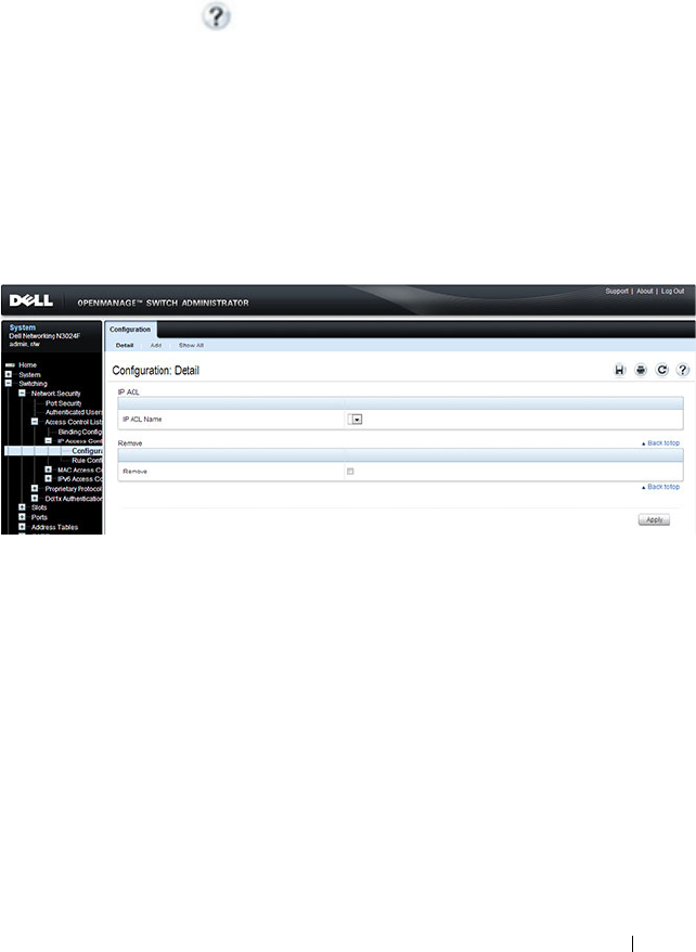
Configuring Access Control Lists 599
Configuring ACLs (Web)
This section provides information about the OpenManage Switch
Administrator pages for configuring and monitoring ACLs on a Dell
Networking N2000, N3000, and N4000 series switches. For details about the
fields on a page, click at the top of the page.
IP ACL Configuration
Use the IP ACL Configuration page to add or remove IP-based ACLs.
To display the IP ACL Configuration page, click Switching
→
Network
Security
→
Access Control Lists
→
IP Access Control Lists
→
Configuration in the navigation panel.
Figure 20-1. IP ACL Configuration
Adding an IPv4 ACL
To add an IPv4 ACL:
1
Open the
IP ACL Configuration
page.
2
Click
Add
to display the
Add IP ACL
page.
3
Specify an ACL name.
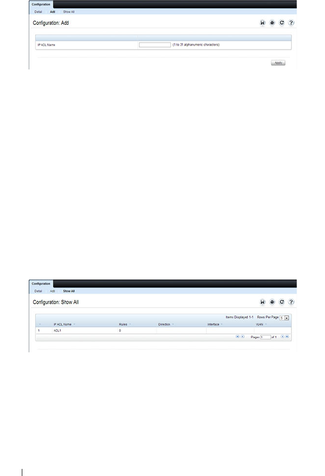
600 Configuring Access Control Lists
Figure 20-2. Add IP ACL
4
Click
Apply
.
Removing IPv4 ACLs
To delete an IPv4 ACL:
1
From the
IP ACL Name
menu on the
IP ACL Configuration
page, select
the ACL to remove.
2
Select the
Remove
checkbox.
3
Click
Apply
.
Viewing IPv4 ACLs
To view configured ACLs, click Show All from the IP ACL Configuration
page.
Figure 20-3. View IPv4 ACLs

Configuring Access Control Lists 601
IP ACL Rule Configuration
Use the IP ACL Rule Configuration page to define rules for IP-based ACLs.
The access list definition includes rules that specify whether traffic matching
the criteria is forwarded normally or discarded. Additionally, you can specify
to assign traffic to a particular queue, filter on some traffic, change VLAN tag,
shut down a port, and/or redirect the traffic to a particular port.
To display the IP ACL Rule Configuration page, click Switching
→
Network
Security
→
Access Control Lists
→
IP Access Control Lists
→
Rule
Configuration in the navigation panel.
NOTE: There is an implicit deny all rule at the end of an ACL list. This means that
if an ACL is applied to a packet and if none of the explicit rules match, then the
final implicit "deny all" rule applies and the packet is dropped.
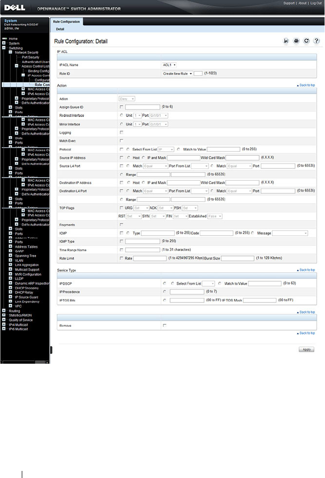
602 Configuring Access Control Lists
Figure 20-4. IP ACL - Rule Configuration
Removing an IP ACL Rule
To delete an IP ACL rule:
1
From the
Rule ID
menu, select the ID of the rule to delete.
2
Select the
Remove
option near the bottom of the page.
3
Click
Apply
to remove the selected rule.
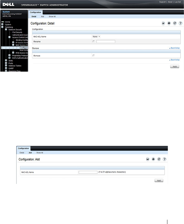
Configuring Access Control Lists 603
MAC ACL Configuration
Use the MAC ACL Configuration page to define a MAC-based ACL.
To display the MAC ACL Configuration page, click Switching
→
Network
Security
→
Access Control Lists
→
MAC Access Control Lists
→
Configuration in the navigation panel.
Figure 20-5. MAC ACL Configuration
Adding a MAC ACL
To add a MAC ACL:
1
Open the
MAC ACL Configuration
page.
2
Click
Add
to display the
Add MAC ACL
page.
3
Specify an ACL name.
Figure 20-6. Add MAC ACL
4
Click
Apply
.

604 Configuring Access Control Lists
Renaming or Removing MAC ACLs
To rename or delete a MAC ACL:
1
From the
MAC ACL Name
menu on the
MAC ACL Configuration
page, select the ACL to rename or remove.
2
To rename the ACL, select the
Rename
checkbox and enter a new name in
the associated field.
3
To remove the ACL, select the
Remove
checkbox.
4
Click
Apply
.
Viewing MAC ACLs
To view configured ACLs, click Show All from the MAC ACL Configuration
page.
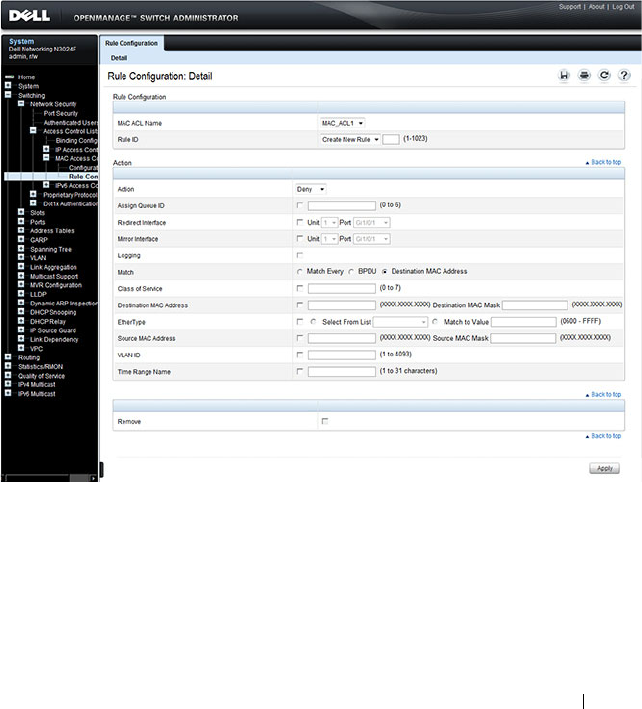
Configuring Access Control Lists 605
MAC ACL Rule Configuration
Use the MAC ACL Rule Configuration page to define rules for MAC-based
ACLs. The access list definition includes rules that specify whether traffic
matching the criteria is forwarded normally or discarded. A default deny all
rule is the last rule of every list.
To display the MAC ACL Rule Configuration page, click Switching
→
Network Security
→
Access Control Lists
→
MAC Access Control Lists
→
Rule Configuration in the navigation panel.
Figure 20-7. MAC ACL Rule Configuration
Removing a MAC ACL Rule
To delete a MAC ACL rule:
1
From the
Rule ID
menu, select the ID of the rule to delete.
2
Select the
Remove
option near the bottom of the page.
3
Click
Apply
to remove the selected rule.
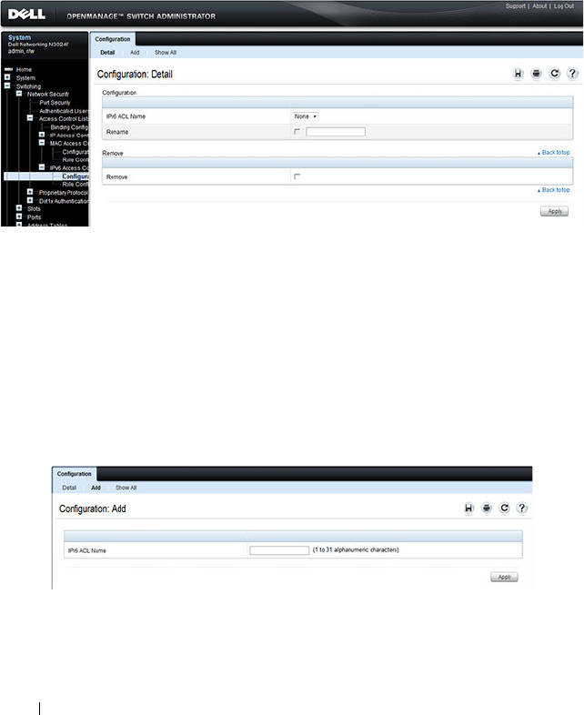
606 Configuring Access Control Lists
IPv6 ACL Configuration
Use the IPv6 ACL Configuration page to add or remove IP-based ACLs. To
display the IP ACL Configuration page, click Switching
→
Network Security
→
Access Control Lists
→
IPv6 Access Control Lists
→
IPv6 ACL
Configuration in the navigation panel.
Figure 20-8. IPv6 ACL Configuration
Adding an IPv6 ACL
To add an IPv6 ACL:
1
Open the
IPv6 ACL Configuration
page.
2
Click
Add
to display the
Add IPv6 ACL
page.
3
Specify an ACL name.
Figure 20-9. Add IPv6 ACL
4
Click
Apply
.

Configuring Access Control Lists 607
Removing IPv6 ACLs
To delete an IPv6 ACL:
1
From the
IPv6 ACL Name
menu on the
IPv6 ACL Configuration
page,
select the ACL to remove.
2
Select the
Remove
checkbox.
3
Click
Apply
.
Viewing IPv6 ACLs
To view configured ACLs, click Show All from the IPv6 ACL Configuration
page. The IPv6 ACL Table page displays.
IPv6 ACL Rule Configuration
Use the IPv6 ACL Rule Configuration page to define rules for IPv6-based
ACLs. The access list definition includes rules that specify whether traffic
matching the criteria is forwarded normally or discarded. Additionally, you
can specify to assign traffic to a particular queue, filter on some traffic,
change VLAN tag, shut down a port, and/or redirect the traffic to a particular
port. By default, no specific value is in effect for any of the IPv6 ACL rules.
There is an implicit deny all rule at the end of an ACL list. This means that if
an ACL is applied to a packet and if none of the explicit rules match, then the
final implicit deny all rule applies and the packet is dropped.
To display the IPv6 ACL Rule Configuration page, click Switching
→
Network Security
→
Access Control Lists
→
IPv6 Access Control Lists
→
Rule Configuration in the navigation menu.
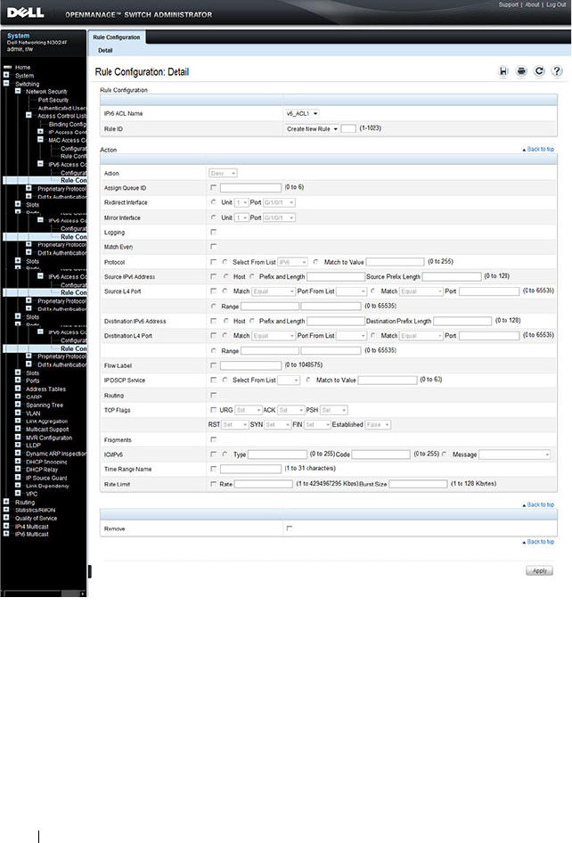
608 Configuring Access Control Lists
Figure 20-10. IPv6 ACL - Rule Configuration
Removing an IPv6 ACL Rule
To delete an IPv6 ACL rule:
1
From the
Rule ID
menu, select the ID of the rule to delete.
2
Select the
Remove
option near the bottom of the page.
3
Click
Apply
to remove the selected rule.

Configuring Access Control Lists 609
ACL Binding Configuration
When an ACL is bound to an interface, all the rules that have been defined
are applied to the selected interface. Use the ACL Binding Configuration
page to assign ACL lists to ACL Priorities and Interfaces.
From the web interface, you can configure the ACL rule in the ingress or
egress direction so that the ACLs implement security rules for packets
entering or exiting the port. You can apply ACLs to any physical (including 10
Gb) interface, LAG, or routing port.
To display the ACL Binding Configuration page, click Switching
→
Network
Security
→
Access Control Lists
→
Binding Configuration in the navigation
panel.
Figure 20-11. ACL Binding Configuration
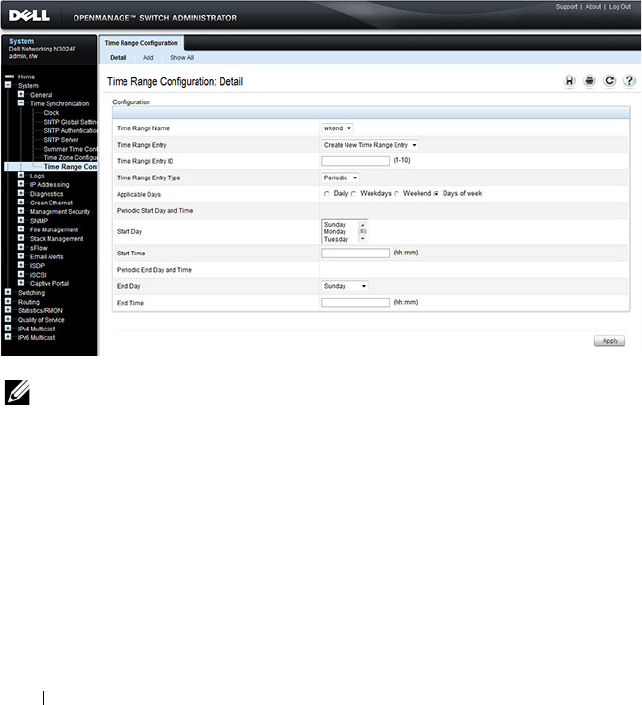
610 Configuring Access Control Lists
Time Range Entry Configuration
Use the Time Range Entry Configuration page to define time ranges to
associate with ACL rules.
To display the Time Range Entry Configuration page, click System
→
Time
Synchronization
→
Time Range Configuration in the navigation panel. The
following image shows the page after at least one time range has been added.
Otherwise, the page indicates that no time ranges are configured, and the
time range configuration fields are not displayed.
Figure 20-12. Time Range Configuration
NOTE: A time-range parameter in an ACL that is referred to by a route-map
statement is active only during the time range specified. When the ACL is not active
(outside the time range), the route-map simply treats the ACL as a “no match”.
Adding a Time Range
To configure a time range:
1
From the
Time Range Entry Configuration page, click Add.
2
Specify a name to identify the time range.
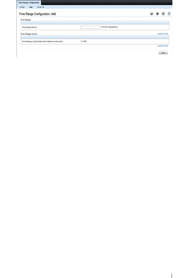
Configuring Access Control Lists 611
Figure 20-13. Add a Time Range
3
Click
Apply
.
4
Click
Configuration
to return to the
Time Range Entry Configuration
page.
5
In the
Time Range Name
field, select the name of the time range to
configure.
6
Specify an ID for the time range. You can configure up to 10 different time
range entries to include in the named range. However, only one absolute
time entry is allowed per time range.
7
Configure the values for the time range entry.
8
Click
Apply
.
9
To add additional entries to the named time range, repeat step 5 through
step 8.

612 Configuring Access Control Lists
Configuring ACLs (CLI)
This section provides information about the commands you use to create and
configure ACLs. For more information about the commands, see the
Dell
Networking N2000, N3000, and N4000 Series Switches CLI Reference Guide
at support.dell.com/manuals.
Configuring an IPv4 ACL
Beginning in Privileged EXEC mode, use the following commands to create
an IPv4 ACL, configure rules for the ACL, and bind the ACL to an interface.
NOTE: The ip access-group command can be issued in Global Configuration
mode or Interface configuration mode. If it is applied in Global Configuration
mode, the ACL binding is applied to all interfaces. If it is applied in Interface
Configuration mode, it is applied only to the specified interfaces within the mode.
Command Purpose
configure Enter global configuration mode.
access-list name Create an extended ACL and enter IPv4 access-list
configuration mode.

Configuring Access Control Lists 613
{deny | permit} {every |
{{
ipv4-protocol
|
0-255
|
every
} {
srcip srcmask
|
any | host
srcip
} [{range
{
portkey
|
startport
}
{
portkey
|
endport
} |
{eq | neq | lt | gt}
{
portkey
|
0-65535
} ]
{
dstip dstmask
| any |
host
dstip
} [{range
{
portkey
|
startport
}
{
portkey
|
endport
} |
{eq | neq | lt | gt}
{
portkey
|
0-65535
}]
[flag [+fin | -fin] [+syn
| -syn] [+rst | -rst]
[+psh | -psh] [+ack | -
ack] [+urg | -urg]
[established]] [icmp-
type
icmp-type
[icmp-
code
icmp-code
] | icmp-
message
icmp-message
]
[igmp-type
igmp-type
]
[fragments] [precedence
precedence
| tos
tos
[
tosmask
] | dscp
dscp
]}} [time-range
time-range-name
] [log]
[assign-queue
queue-id
]
[{mirror | redirect}
unit/slot/port
] [rate-
limit
rate burst-size
]
Enter the permit and deny conditions for the extended
ACL.
•{
deny | permit
}–Specifies whether the IP ACL rule
permits or denies the matching traffic.
•
{
ipv4-protocol
|
number
|
every
}—
Specifies the
protocol to match for the IP ACL rule.
– IPv4 protocols:
eigrp, gre, icmp, igmp, ip, ipinip, ospf,
tcp, udp, pim
–
Every
: Match any protocol (don’t care)
•
srcip
srcmask
| any | host
srcip
—Specifies a source IP
address and netmask to match for the IP ACL rule.
– Specifying “any” implies specifying
srcip
as “0.0.0.0”
and
srcmask
as “255.255.255.255” for IPv4.
– Specifying “host A.B.C.D” implies
srcip
as “A.B.C.D”
and
srcmask
as “0.0.0.0”.
•
[{{eq | neq | lt | gt} {
portkey
|
number
} | range
startport endport
}]
—Specifies the layer 4 destination
port match condition for the IP ACL rule. A destination
port number, which ranges from 0-65535, can be entered,
or a
portkey
, which can be one of the following keywords:
domain, echo, ftp, ftp-data, http, smtp, snmp, telnet,
tftp, and www. Each of these keywords translates into its
equivalent destination port number.
– When “range” is specified, IP ACL rule matches only if
the layer 4 port number falls within the specified
portrange. The
startport
and
endport
parameters
identify the first and last ports that are part of the port
range. They have values from 0 to 65535. The ending
port must have a value equal or greater than the
starting port. The starting port, ending port, and all
ports in between will be part of the layer 4 port range.
Command Purpose

614 Configuring Access Control Lists
continued
– When “eq” is specified, IP ACL rule matches only if
the layer 4 port number is equal to the specified port
number or portkey.
– When “lt” is specified, IP ACL rule matches if the layer
4 destination port number is less than the specified
port number or portkey. It is equivalent to specifying
the range as 0 to <specified port number – 1>.
– When “gt” is specified, IP ACL rule matches if the
layer 4 destination port number is greater than the
specified port number or portkey. It is equivalent to
specifying the range as <specified port number + 1>
to 65535.
– When “neq” is specified, IP ACL rule matches only if
the layer 4 destination port number is not equal to the
specified port number or portkey.
– IPv4 TCP port names
: bgp, domain, echo, ftp, ftp-
data, http, smtp, telnet, www, pop2, pop3
–IPv4 UDP port names:
domain, echo, ntp, rip, snmp,
tftp, time, who
•
dstip
dstmask
|
any | host
dstip
—Specifies a destination
IP address and netmask for match condition of the IP
ACL rule.
– Specifying “any” implies specifying
dstip
as “0.0.0.0”
and
dstmask
as “255.255.255.255”.
– Specifying “host A.B.C.D” implies
dstip
as “A.B.C.D”
and
dstmask
as “0.0.0.0”.
•
[precedence
precedence
| tos
tos
[
tosmask
] | dscp
dscp
]—
Specifies the TOS for an IP/TCP/UDP ACL rule
depending on a match of precedence or DSCP values
using the parameters dscp, precedence, or tos tosmask.
Command Purpose

Configuring Access Control Lists 615
continued
•
flag [+fin | -fin] [+syn | -syn] [+rst | -rst] [+psh | -
psh] [+ack | -ack] [+urg | -urg] [established]—
Specifies that the IP/TCP/UDP ACL rule matches on the
TCP flags.
–
Ack
– Acknowledgement bit
–
Fin
– Finished bit
–
Psh
– push bit
–
Rst
– reset bit
–
Syn
– Synchronize bit
–
Urg
– Urgent bit
– When “+<tcpflagname>
”
is specified, a match occurs
if specified <tcpflagname> flag is set in the TCP
header.
– When “-<tcpflagname>
”
is
specified, a match occurs
if specified <tcpflagname> flag is *NOT* set in the
TCP header.
– When “established
” is
specified, a match occurs if
either the RST or ACK bits are set in the TCP header.
– This option is visible only if protocol is “tcp”.
•
[icmp-type
icmp-type
[icmp-code
icmp-code
] |
icmp-
message
icmp-message
] —
Specifies a match condition
for ICMP packets.
– When icmp-type is specified, IP ACL rule matches on
the specified ICMP message type, a number from 0
to 255.
– When icmp-code is specified, IP ACL rule matches on
the specified ICMP message code, a number from 0
to 255.
– Specifying icmp-message implies both icmp-type and
icmp-code are specified.
– ICMP message is decoded into corresponding ICMP
type and ICMP code within that ICMP type. This
option is visible only if the protocol is “icmp”.
– IPv4 ICMP message types: echo echo-reply host-
redirect mobile-redirect net-redirect net-unreachable
redirect packet-too-big port-unreachable source-
quench router-solicitation router-advertisement time-
exceeded ttl-exceeded unreachable
Command Purpose

616 Configuring Access Control Lists
continued
•igmp-type
igmp-type
—When igmp-type is specified, IP
ACL rule matches on the specified IGMP message type
(i.e., a number from 0 to 255).
•
fragments—
Specifies the rule matches packets that are
non-initial fragments (fragment bit asserted). Not valid
for rules that match L4 information such as TCP port
number since that information is carried in the initial
packet.
This keyword is visible only if the protocol is IP, TCP, or
UDP.
•
log—
Specifies that this rule is to be logged.
•time-range
time-range-name
—Allows imposing time
limitation on the ACL rule as defined by the parameter
time-range-name. If a time range with the specified name
does not exist and the ACL containing this ACL rule is
applied to an interface or bound to a VLAN, then the
ACL rule is applied immediately. If a time range with
specified name exists and the ACL containing this ACL
rule is applied to an interface or bound to a VLAN, then
the ACL rule is applied when the time-range with
specified name becomes active. The ACL rule is removed
when the time-range with specified name becomes
inactive.
• assign-queue
queue-id
—Specifies the assign-queue,
which is the queue identifier to which packets matching
this rule are assigned.
•
{mirror | redirect}
unit/slot/ port
—Specifies the mirror
or redirect interface which is the unit/slot/port to which
packets matching this rule are copied or forwarded,
respectively.
•
rate-limit
rate burst-size
—Specifies the allowed rate of
traffic as per the configured rate in kbps, and burst-size in
kbytes.
– Rate – the committed rate in kilobits per second
– Burst-size – the committed burst size in Kilobytes.
Command Purpose

Configuring Access Control Lists 617
interface
interface
(Optional) Enter interface configuration mode for the
specified interface. The
interface
variable includes the
interface type and number, for example tengigabitethernet
1/0/3.
You can also specify a range of interfaces with the interface
range command, for example, interface range
tengigabitethernet 1/0/8-12 configures interfaces 8, 9, 10,
11, and 12.
ip access-group
name
direction seqnum
Bind the specified ACL to an interface.
NOTE: To apply this ACL to all interfaces, issue the command
in Global Configuration mode.
•
name
— Access list name. (Range: Valid IP access-list
name up to 31 characters in length)
•
direction
— Direction of the ACL. (Range: In or out.
Default is
in
.)
•
seqnum
— Precedence for this interface and direction. A
lower sequence number has higher precedence. Range: 1
– 4294967295. Default is1.
CTRL + Z Exit to Privileged EXEC mode.
show ip access-lists
[
name
]
Display all IPv4 access lists and all of the rules that are
defined for the IPv4 ACL. Use the optional
name
parameter to identify a specific IPv4 ACL to display.
Command Purpose

618 Configuring Access Control Lists
Configuring a MAC ACL
Beginning in Privileged EXEC mode, use the following commands to create
an MAC ACL, configure rules for the ACL, and bind the ACL to an interface.
Command Purpose
configure Enter global configuration mode.
mac access-list extended
name
Create a named MAC ACL. This command also enters
MAC Access List Configuration mode. If a MAC ACL
with this name already exists, this command enters the
mode to update the existing ACL.
{deny | permit}
{
srcmac
srcmacmask
|
any} {
dstmac
dstmacmask
| any |
bpdu} [{
ethertypekey
|
0x0600-0xFFFF
} [vlan
eq
0-4093
] [cos
0-7
]
[secondary-vlan eq
0-
4093
] [secondary-cos
0-
7
] [log] [time-range
time-range-name
]
[assign-queue
queue-id
]
[{mirror |redirect}
interface
]
Specify the rules (match conditions) for the MAC access
list.
•
srcmac
— Valid source MAC address in format
xxxx.xxxx.xxxx.
•
srcmacmask
— Valid MAC address bitmask for the source
MAC address in format xxxx.xxxx.xxxx.
•
any
— Packets sent to or received from any MAC address
•
dstmac
— Valid destination MAC address in format
xxxx.xxxx.xxxx.
•
destmacmask
— Valid MAC address bitmask for the
destination MAC address in format xxxx.xxxx.xxxx.
•
bpdu
— Bridge protocol data unit
•
ethertypekey
— Either a keyword or valid four-digit
hexadecimal number. (Range: Supported values are
appletalk, arp, ibmsna, ipv4, ipv6, ipx, mplsmcast,
mplsucast, Netbios, novell, pppoe, rarp.)
•
0x0600-0xFFFF
— Specify custom EtherType value
(hexadecimal range 0x0600-0xFFFF)
•
vlan eq
— VLAN number. (Range 0-4093)
•
cos
— Class of service. (Range 0-7)
•
log
— Specifies that this rule is to be logged.
•
time-range-name
— Specifies the named time range to
associate with the ACL rule.

Configuring Access Control Lists 619
continued
– When “gt” is specified, IPv6 ACL rule matches if the
layer 4 destination port number is greater than the
specified port number or portkey. It is equivalent to
specifying the range as <specified port number + 1>
to 65535.
– When “neq” is specified, IPv6 ACL rule matches only if
the layer 4 destination port number is not equal to the
specified port number or portkey.
– IPv6 TCP port names:
bgp, domain, echo, ftp, ftp-
data, http, smtp, telnet, www, pop2, pop3
–IPv6 UDP port names:
domain, echo, ntp, rip, snmp,
time, who
•
destination-ipv6-prefix
/
prefix-length
|
any
|
host
destination-ipv6-address
—Specifies a destination IP
address and netmask for match condition of the IP ACL
rule.
– For IPv6 ACLs, “any” implies 0::/128 prefix and a mask
of all ones.
– Specifying host implies prefix length as “/128” and a
mask of 0::/128.
• [precedence
precedence
| tos
tos
[
tosmask
] | dscp
dscp
]—Specifies the TOS for an IP/TCP/UDP ACL rule
depending on a match of precedence or DSCP values
using the parameters dscp, precedence, or tos tosmask.
• flag [+fin | -fin] [+syn | -syn] [+rst | -rst] [+psh | -
psh] [+ack | -ack] [+urg | -urg] [established]—Specifies
that the IP/TCP/UDP ACL rule matches on the TCP
flags.
– When “+<tcpflagname>
” is
specified, a match occurs
if specified <tcpflagname> flag is set in the TCP
header.
– When “-<tcpflagname>
” is
specified, a match occurs
if specified <tcpflagname> flag is *NOT* set in the
TCP header.
– When “established
” is
specified, a match occurs if
specified either RST or ACK bits are set in the TCP
header.
Command Purpose

620 Configuring Access Control Lists
continued
– This option is visible only if the protocol is tcp.
–
Ack
– Acknowledgement bit
–
Fin
– Finished bit
–
Psh
– push bit
–
Rst
– reset bit
–
Syn
– Synchronize bit
–
Urg
– Urgent bit
•[icmp-type
icmp-type
[icmp-code
icmp-code
] | icmp-
message
icmp-message
]—Specifies a match condition for
ICMP packets.
– When icmp-type is specified, IP ACL rule matches on
the specified ICMP message type, a number from 0
to 255.
– When icmp-code is specified, IP ACL rule matches on
the specified ICMP message code, a number from 0
to 255.
– Specifying icmp-message implies both icmp-type and
icmp-code are specified.
– ICMP message is decoded into corresponding ICMP
type and ICMP code within that ICMP type. This
option is visible only if the protocol is “icmpv6”.
– ICMPv6 message types: destination-unreachable echo-
reply echo-request header hop-limit mld-query mld-
reduction mld-report nd-na nd-ns next-header no-
admin no-route packet-too-big port-unreachable
router-solicitation router-advertisement router-
renumbering time-exceeded unreachable
– The icmpv6 message types are available only if the
protocol is icmpv6.
• fragments—Specifies the rule matches packets that are
non-initial fragments (fragment bit asserted). Not valid
for rules that match L4 information such as TCP port
number since that information is carried in the initial
packet. IPv6 fragments contain an IPv6 Fragment
extension header.
Command Purpose

Configuring Access Control Lists 621
continued
• routing—Specifies that IP ACL rule matches on routed
packets. Routed packets contain an IPv6 “routing”
extension header.
• log—Specifies that this rule is to be logged.
•time-range
time-range-name
—Allows imposing time
limitation on the ACL rule as defined by the parameter
time-range-name. If a time range with the specified name
does not exist and the ACL containing this ACL rule is
applied to an interface or bound to a VLAN, then the
ACL rule is applied immediately. If a time range with
specified name exists and the ACL containing this ACL
rule is applied to an interface or bound to a VLAN, then
the ACL rule is applied when the time-range with
specified name becomes active. The ACL rule is removed
when the time-range with specified name becomes
inactive.
• assign-queue
queue-id
—Specifies the assign-queue,
which is the queue identifier to which packets matching
this rule are assigned.
• {mirror | redirect}
unit/slot/ port
—Specifies the mirror
or redirect interface which is the unit/slot/port to which
packets matching this rule are copied or forwarded,
respectively.
•rate-limit
rate burst-size
—Specifies the allowed rate of
traffic as per the configured rate in kbps, and burst-size in
kbytes.
– Rate – the committed rate in kilobits per second
– Burst-size – the committed burst size in Kilobytes.
interface
interface
(Optional) Enter interface configuration mode for the
specified interface. The
interface
variable includes the
interface type and number, for example tengigabitethernet
1/0/3.
You can also specify a range of interfaces with the interface
range command, for example, interface range
tengigabitethernet 1/0/8-12 configures interfaces 8, 9, 10,
11, and 12.
Command Purpose

622 Configuring Access Control Lists
mac access-group
name
direction seqnum
Bind the specified MAC ACL to an interface.
NOTE: To apply this ACL to all interfaces, issue the command
in Global Configuration mode.
•
name
— Access list name. (Range: Valid MAC access-list
name up to 31 characters in length)
•
direction
— Direction of the ACL. (Range: In or out.
Default is
in
.)
•
seqnum
— Precedence for this interface and direction. A
lower sequence number has higher precedence. Range: 1
– 4294967295. Default is1.
CTRL + Z Exit to Privileged EXEC mode.
show mac access-lists
[
name
]
Display all MAC access lists and all of the rules that are
defined for the MAC ACL. Use the optional
name
parameter to identify a specific MAC ACL to display.
Command Purpose

Configuring Access Control Lists 623
Configuring an IPv6 ACL
Beginning in Privileged EXEC mode, use the following commands to create
an IPv6 ACL, configure rules for the ACL, and bind the ACL to an interface.
Command Purpose
configure Enter global configuration mode.
ipv6 traffic-filter
name
Create an extended IPv6 ACL. This command also enters
IPv6 Access List Configuration mode. If an IPv6 ACL with
this name already exists, this command enters the mode to
update the existing ACL.

624 Configuring Access Control Lists
{deny | permit} {ipv6-
protocol | number |
every} {
source-ipv6-
prefix/prefix-length
| any
|
host source-ipv6-
address
} [{range
{
portkey
|
startport
}
{
portkey
|
endport
} |
{eq | neq | lt | gt}
{
portkey
|
0-65535
}]
{
destination-ipv6-
prefix/prefix-length
| any
|
host destination-ipv6-
address
} [{range
{
portkey
|
startport
}
{
portkey
|
endport
} |
{eq | neq | lt | gt}
{
portkey
|
0-65535
}]
[flag [+fin | -fin] [+syn
| -syn] [+rst | -rst]
[+psh | -psh] [+ack | -
ack] [+urg | -urg]
[established]] [flow-
label
value
] [icmp-type
icmp-type
[icmp-code
icmp-code
] | icmp-
message
icmp-message
]
[routing] [fragments]
[dscp
dscp
]}} [log]
[assign-queue
queue-id
]
[{mirror | redirect}
unit/slot/port
] [rate-
limit
rate burst-size
]
•{
deny | permit
}–Specifies whether the IP ACL rule
permits or denies the matching traffic.
•{
ipv6-protocol
|
number
|
every
}—Specifies the protocol
to match for the IP ACL rule.
– IPv4 protocols:
icmpv6, ipv6, tcp and udp
–
Every
: Match any protocol (don’t care)
•
source-ipv6-prefix
/prefixlength |
any | host
src-ipv6-
address
—Specifies a source IP address and netmask to
match for the IP ACL rule.
– For IPv6 ACLs, “any” implies a 0::/128 prefix and a
mask of all ones.
– Specifying “host X::X” implies a prefix length as “/128”
and a mask of 0::/128.
•[{range {
portkey
|
startport
} {
portkey
|
endport
} | {eq |
neq | lt | gt} {
portkey
|
0-65535
}]—Specifies the layer 4
destination port match condition for the IP/TCp/UDP
ACL rule. A destination port number, which ranges from
0-65535, can be entered, or a
portkey
, which can be one of
the following keywords: bgp, domain, echo, ftp, ftp-data,
http, ntp, pop2, pop3, rip, smtp, snmp, telnet, tftp,
telnet, time, who and www. Each of these keywords
translates into its equivalent destination port number.
– When “range” is specified, IPv6 ACL rule matches only
if the layer 4 port number falls within the specified
portrange. The
startport
and
endport
parameters
identify the first and last ports that are part of the port
range. They have values from 0 to 65535. The ending
port must have a value equal or greater than the
starting port. The starting port, ending port, and all
ports in between will be part of the layer 4 port range.
– When “eq” is specified, IPv6 ACL rule matches only if
the layer 4 port number is equal to the specified port
number or portkey.
– When “lt” is specified, IPv6 ACL rule matches if the
layer 4 destination port number is less than the
specified port number or portkey. It is equivalent to
specifying the range as 0 to <specified port number –
1>.
Command Purpose

Configuring Access Control Lists 625
(Continued)
•
destination ipv6 prefix
— IPv6 prefix in IPv6 global
address format.
•
flow label
value
— The value to match in the Flow Label
field of the IPv6 header (Range 0–1048575).
•
dscp
dscp
— Specifies the TOS for an IPv6 ACL rule
depending on a match of DSCP values using the
parameter dscp.
•
log
— Specifies that this rule is to be logged.
•
time-range-name
— Specifies the named time range to
associate with the ACL rule.
•
assign-queue
queue-id
— Specifies particular hardware
queue for handling traffic that matches the rule.
•
mirror
interface
— Allows the traffic matching this rule
to be copied to the specified interface.
•
redirect
interface
— This parameter allows the traffic
matching this rule to be forwarded to the specified
interface.
interface
interface
(Optional) Enter interface configuration mode for the
specified interface. The
interface
variable includes the
interface type and number, for example tengigabitethernet
1/0/3.
You can also specify a range of interfaces with the interface
range command, for example, interface range
tengigabitethernet 1/0/8-12 configures interfaces 8, 9, 10,
11, and 12.
ipv6 traffic-filter
name
direction
[sequence
seq-
num
]
Bind the specified IPv6 ACL to an interface.
NOTE: To apply this ACL to all interfaces, issue the command
in Global Configuration mode.
•
name
— Access list name. (Range: Valid IPv6 access-list
name up to 31 characters in length)
•
direction
— Direction of the ACL. (Range: In or out.
Default is
in
.)
•
seqnum
— Precedence for this interface and direction. A
lower sequence number has higher precedence. Range: 1
– 4294967295. Default is1.
Command Purpose

626 Configuring Access Control Lists
Configuring a Time Range
Beginning in Privileged EXEC mode, use the following commands to create a
time range and configure time-based entries for the time range.
CTRL + Z Exit to Privileged EXEC mode.
show ipv6 access-lists
[
name
]
Display all IPv6 access lists and all of the rules that are
defined for the IPv6 ACL. Use the optional
name
parameter to identify a specific IPv6 ACL to display.
Command Purpose
configure Enter global configuration mode.
time-range
name
Create a named time range and enter the Time-Range
Configuration mode for the range.
absolute {[start
time
date
] [end
time date
]}
Configure a nonrecurring time entry for the named time
range.
•
start
time
date
— Time and date the ACL rule starts
going into effect. The time is expressed in a 24-hour
clock, in the form of hours:minutes. For example, 8:00 is
8:00 am and 20:00 is 8:00 pm. The date is expressed in
the format day month year. If no start time and date are
specified, the configuration statement is in effect
immediately.
•
end
time
date
— Time and date the ACL rule is no
longer in effect.
Command Purpose

Configuring Access Control Lists 627
periodic {
days-of-the-
week time
} to {[
days-of-
the-week
]
time
}
Configure a recurring time entry for the named time
range.
•
days-of-the-week
—The first occurrence indicates the
starting day(s) the ACL goes into effect. The second
occurrence is the ending day(s) when the ACL rule is no
longer in effect. If the end
days-of-the-week
are the same
as the start, they can be omitted
This variable can be any single day or combinations of
days:
Monday
,
Tues day
,
Wednesday
,
Thursday
,
Friday
,
Saturday
,
Sunday
. Other possible values are:
–
daily
-- Monday through Sunday
–
weekdays
-- Monday through Friday
–
weekend
-- Saturday and Sunday
•
time
— Time the ACL rule starts going into effect (first
occurrence) or ends (second occurrence). The time is
expressed in a 24-hour clock, in the form of
hours:minutes.
CTRL + Z Exit to Privileged EXEC mode.
show time-range [
name
] View information about all configured time ranges,
including the absolute/periodic time entries that are
defined for each time range. Use the
name
variable to view
information about the specified time range.
Command Purpose

628 Configuring Access Control Lists
ACL Configuration Examples
This section contains the following examples:
•"Basic Rules" on page628
•"Internal System ACLs" on page629
•"Complete ACL Example" on page629
• "Advanced Examples" on page 633
• "Policy Based Routing Examples" on page 640
Basic Rules
• Inbound rule allowing all packets:
permit every
Administrators should be cautious when using the
permit every
rule in an
access list, especially when using multiple access lists. All packets match a
permit every
rule and no further processing is done on the packet. This
means that a
permit every
match in an access list will skip processing
subsequent rules in the current or subsequent access-lists and allow all
packets not previously denied by a prior rule.
• Inbound rule to drop all packets:
As the last rule in a list, this rule is redundant as an implicit "deny every" is
added after the end of the last access-group configured on an interface.
deny every
Administrators should be cautious when using the
deny every
rule in an
access list, especially when using multiple access lists. When a packet
matches a rule, no further processing is done on the packet. This means
that a
deny every
match in an access list will skip processing subsequent
rules in the current or subsequent access-lists and drop all packets not
previously allowed by a prior rule.
• Inbound rule allowing access FROM hosts with IP addresses ranging from
10.0.46.0 to 10.0.47.254:
NOTE: None of these ACL rules are applicable to the OOB interface.

Configuring Access Control Lists 629
permit ip 10.0.46.0 0.0.1.255 any
• Inbound rule allowing access TO hosts with IP addresses ranging from
10.0.48.0 to 10.0.49.254:
permit ip any 10.0.48.0 0.0.1.255
As the last rule in an administrator-defined list, the narrower scope of this
inbound rule has no effect other than to possibly interfere with switch
operations. The system installs an implicit deny every rule after the end of
the last access group bound to an interface:
deny ip any any
Internal System ACLs
The switch installs a number of internal ACLS to trap packets to the CPU for
processing. Examples of these types of packets are spanning tree BPDUs,
IEEE 802.1x EAPOL packets, iSCSI packets, IP source guard packets, LLPF
packets, LLDP packets, IEEE 802.1AD packets, etc. These internal ACLs are
generally configured at the lowest priority (higher numerically) so that the
switch administrator, through the use of ACLs, can override the default
switch behavior. Some of the system rules are installed when the
administrator enables specific protocols; other rules are always present and
may have their behaviors altered by enabling or disabling protocols. For
example, spanning tree BPDUs, LLDP packets, and IEEE 802.1X packets are
never forwarded by the switch.
Complete ACL Example
The following example is a complete inbound ACL that allows access for
hosts connected to gi1/0/1 with IP address in 10.1.1.x range to send IP packets
to 192.168.0.X hosts on gi1/0/2. IP packets not from 10.1.1.x addresses or not
addressed to 192.168.0.x hosts are dropped. Packets with protocols other than
IP, DNS, ARP, or ICMP are dropped. Allowing ICMP supports the 10.1.1.x
hosts in reliably receiving and initiating TCP connections and pinging
through the switch. This example also allows ARP and DNS packets to any
destination and is suitable for an L2 switch.
mac access-list extended Allow-ARP
permit any any arp
exit

630 Configuring Access Control Lists
ip access-list Allow-10-1-1-x
permit ip 10.1.1.0 0.0.0.255 192.168.0.0 0.0.0.255
permit icmp 10.1.1.0 0.0.0.255 any
permit ip 0.0.0.0 255.255.255.255 any
permit udp any any eq domain
exit
interface gi1/0/1
mac access-group Allow-ARP in 10
ip access-group Allow-10-1-1-x in 20
exit
Another list on the 192.168.0.x network attached port (gi1/0/2) is configured
for this example. Because the two access lists are complementary/end-to-end,
it is necessary to allow ICMP packets to travel between the attached hosts.
ip access-list Allow-192-168-0-x
permit ip 192.168.0.0 0.0.0.255 10.1.1.0 0.0.0.255
permit icmp 192.168.0.0 0.0.0.255 any
permit udp any any eq domain
exit
interface gi1/0/2
mac access-group Allow-ARP in 10
ip access-group Allow-192-168-0-x in 20
exit
Consider the following inbound rules that allow Telnet connections and UDP
traffic from the 192.168.0.x network to host 10.1.1.23:
ip access-list Host10-1-1-23
! Permit Telnet traffic from 192.168.0.X network to host 10.1.1.23
permit tcp 192.168.0.0 0.0.0.255 host 10.1.1.23 eq telnet
! Permit TCP traffic from 192.168.0.X network to host 10.1.1.23
permit tcp 192.168.0.0 0.0.0.255 host 10.1.1.23
! Permit UDP traffic from 192.168.0.X network to host 10.1.1.23
permit udp 192.168.0.0 0.0.0.255 host 10.1.1.23
! Permit IP traffic from 192.168.0.X network to 10.1.1.x network
permit ip 192.168.0.0 0.0.0.255 10.1.1.23 0.0.0.255
In the above list, the fourth rule allows all IP packets between the network
and host. The narrower scope of the first three rules is redundant, as all IP
traffic, including TCP and UDP, is permitted by the fourth rule. The

Configuring Access Control Lists 631
following list has corrected rules that allow Telnet and UDP packets only and
rely on the implicit "deny all" after the end of the last access group to deny
other traffic.
ip access-list Host10-1-1-23
! Permit Telnet traffic from 192.168.0.X network to host 10.1.1.23
permit tcp 192.168.0.0 0.0.0.255 host 10.1.1.23 eq telnet
! Permit UDP traffic from 192.168.0.X network to host 10.1.1.23
permit udp 192.168.0.0 0.0.0.255 host 10.1.1.23
ACLs support TCP and UDP port matching using operators:
ip access-list Host10-1-1-23
! Permit Telnet traffic from 192.168.0.X network to host 10.1.1.23
permit tcp 192.168.0.0 0.0.0.255 host 10.1.1.23 eq telnet
! Permit UDP traffic from 192.168.0.X network to host 10.1.1.23
permit udp 192.168.0.0 0.0.0.255 host 10.1.1.23
ip access-list Host10-1-1-23
! Permit Telnet traffic from 192.168.0.X network to host 10.1.1.23
permit tcp 192.168.0.0 0.0.0.255 host 10.1.1.23 eq telnet
! Permit UDP traffic from 192.168.0.X network to host 10.1.1.23
permit udp 192.168.0.0 0.0.0.255 host 10.1.1.23
The range operator is inclusive of the specified port parameters.
ACLs support TCP flags. If multiple flags are set (+flag) in a single rule, only
packets with the all the same flags asserted are matched (logical AND).
Likewise, if multiple flags are cleared (–flag) in a single rule, only packets with
the same flags cleared are matched. The established keyword matches TCP
packets with either the RST or ACK bits set (logical OR). Flags that are
neither set nor cleared in the rule are not checked in the ACL (don't care or
wildcard).
ip access-list Host10-1-1-23
! Permit Telnet traffic from 192.168.0.X network to host 10.1.1.23
permit tcp 192.168.0.0 0.0.0.255 host 10.1.1.23 eq telnet
! Permit UDP traffic from 192.168.0.X network to host 10.1.1.23
permit udp 192.168.0.0 0.0.0.255 host 10.1.1.23
The following is an example rule to match TCP packets with the PUSH flag
asserted AND the RESET flag cleared. The other flags bits are "don't care":
ip access-list Host10-1-1-23

632 Configuring Access Control Lists
! Permit Telnet traffic from 192.168.0.X network to host 10.1.1.23
permit tcp 192.168.0.0 0.0.0.255 host 10.1.1.23 eq telnet
! Permit UDP traffic from 192.168.0.X network to host 10.1.1.23
permit udp 192.168.0.0 0.0.0.255 host 10.1.1.23
ACLs may also contain a number of shorthand qualifiers for protocols and IP,
TCP, and UDP port numbers, as shown below. Note that not all of these
qualifiers make sense in the context of any given port number; e.g., ftp and
ftp-data only make sense in the context of the IP or UDP protocols, while an
HTTP port number only makes sense in terms of the TCP or IP protocols.
Refer to RFC 1700 or iana.org/protocols for a list of protocol numbers.
ip access-list Host10-1-1-23
! Permit Telnet traffic from 192.168.0.X network to host 10.1.1.23
permit tcp 192.168.0.0 0.0.0.255 host 10.1.1.23 eq telnet
! Permit UDP traffic from 192.168.0.X network to host 10.1.1.23
permit udp 192.168.0.0 0.0.0.255 host 10.1.1.23
ip access-list Host10-1-1-23
! Permit Telnet traffic from 192.168.0.X network to host 10.1.1.23
permit tcp 192.168.0.0 0.0.0.255 host 10.1.1.23 eq telnet
! Permit UDP traffic from 192.168.0.X network to host 10.1.1.23
permit udp 192.168.0.0 0.0.0.255 host 10.1.1.23
ip access-list Host10-1-1-23
! Permit Telnet traffic from 192.168.0.X network to host 10.1.1.23
permit tcp 192.168.0.0 0.0.0.255 host 10.1.1.23 eq telnet
! Permit UDP traffic from 192.168.0.X network to host 10.1.1.23
permit udp 192.168.0.0 0.0.0.255 host 10.1.1.23
To bind an access-list to an interface, use the access-group command. The in
parameter specifies that the ACL is applied to ingress packets. The out
parameter specifies that the ACL is applied to egress packets not generated by
the switch/router. If no in/out parameter is specified, the access list default is
to apply the ACL to ingress packets.
ip access-list Host10-1-1-23
! Permit Telnet traffic from 192.168.0.X network to host 10.1.1.23
permit tcp 192.168.0.0 0.0.0.255 host 10.1.1.23 eq telnet
! Permit UDP traffic from 192.168.0.X network to host 10.1.1.23
permit udp 192.168.0.0 0.0.0.255 host 10.1.1.23

Configuring Access Control Lists 633
Multiple access lists can be configured on an interface. The processing order
is determined by the last parameter on the access-group command where the
lowest sequence number is processed first, followed by the next higher
sequence number, etc.
In this example, access list Host10-1-1-21 is processed first, followed by Host-
1-1-23:
ip access-list Host10-1-1-23
! Permit Telnet traffic from 192.168.0.X network to host 10.1.1.23
permit tcp 192.168.0.0 0.0.0.255 host 10.1.1.23 eq telnet
! Permit UDP traffic from 192.168.0.X network to host 10.1.1.23
permit udp 192.168.0.0 0.0.0.255 host 10.1.1.23
Advanced Examples
Configuring a Time-Based ACL
The following example configures an ACL that denies HTTP traffic from
8:00 pm to 12:00 pm and 1:00 pm to 6:00 pm on weekdays and from 8:30 am
to 12:30 pm on weekends. The ACL affects all hosts connected to ports that
are members of VLAN 100. The ACL permits VLAN 100 members to browse
the Internet only during lunch and after hours.
To configure the switch:
1
Create a time range called work-hours.
console#config
console(config)#time-range work-hours
2
Configure an entry for the time range that applies to the morning shift
Monday through Friday.
console(config-time-range)#periodic weekdays 8:00 to 12:00
3
Configure an entry for the time range that applies to the afternoon shift
Monday through Friday.
console(config-time-range)#periodic weekdays 13:00
to 18:00
4
Configure an entry for the time range that applies to Saturday and Sunday.
console(config-time-range)#periodic weekend 8:30 to 12:30
console(config-time-range)#exit

634 Configuring Access Control Lists
5
Create an ACL named web-limit that denies HTTP traffic during the
work-hours time range.
console(config)#ip access-list web-limit
console(config-ip-acl)#deny tcp any any eq http time-range
work-hours
console(config-ip-acl)#permit every
6
Enter interface configuration mode for VLAN 100 and apply the ACL to
ingress traffic.
console(config)#interface vlan 100
console(config-if-vlan100)#ip access-group weblimit
in
console(config-if-vlan100)#exit
console(config)#exit
7
Verify the configuration.
console(config)#show ip access-lists web-limit
IP ACL Name: web-limit
Rule Number: 1
Action......................................... deny
Match All...................................... FALSE
Protocol....................................... 6(tcp)
Source IP Address.............................. any
Destination IP Address......................... any
Destination Layer 4 Operator................... Equal To
Destination L4 Port Keyword.................... 80(www/http)
Rule Number: 2
Action......................................... permit
Match All...................................... TRUE
Denying FTP Traffic
This example drops incoming FTP setup and data traffic on interfaces
gi1/0/24 to 48. This example is suitable for configuration on a switch or a
router:
ip access-list deny-ftp
!
deny tcp any any eq ftp
deny tcp any any eq ftp-data
permit every
exit

Configuring Access Control Lists 635
interface range gi1/0/24-48
ip access-list deny-ftp in
exit
Allow FTP Traffic Only to an FTP Server
This ACL limits traffic from a router to a directly connected FTP server
(172.16.0.5) on gi1/0/11. Notice that this is an “out” ACL. Traffic to the
router from the FTP server is not affected by this rule. Traffic from the router
to the FTP server is limited to ICMP and packets destined to the FTP ports.
There is no need to add permit rules for all the protocols the router can send
to the host (e.g., ARP, ICMP, LLDP, etc.), as internally generated packets are
not limited by ACLs. Routing must be enabled to process ARPs or they must
be allowed by an explicit rule. We allow ICMP from remote hosts so that the
FTP server can receive ICMP feedback from clients utilizing the FTP service.
A better implementation would narrow the scope of the ICMP to eliminate
ICMP messages not required for the FTP service, e.g., echo, echo-reply,
redirect, timestamp, etc.
ip access-list allow-ftp-server
permit tcp any host 172.16.0.5 eq ftp-data flag established
permit tcp any host 172.16.0.5 eq ftp
permit icmp any any
exit
interface gi1/0/11
ip access-group allow-ftp-server out
exit
Block Incoming Pings
ip access-list no-ping
deny icmp any any icmp-message echo
permit every
exit
interface gi1/0/1
ip access-group no-ping in
exit
Block Incoming Pings and Responses
This example configures an ACL that blocks incoming pings and ping
responses. Since packets generated by the CPU are not affected by ACLs, to
block pinging from the switch we add a rule to block the ping responses.

636 Configuring Access Control Lists
ip access-list no-ping
deny icmp any any icmp-message echo
deny icmp any any icmp-message echo-reply
permit every
exit
interface gi1/0/1
ip access-group no-ping in
exit
Block RFC 1918 Addresses
This ACL may be useful on connections to ISPs to block traffic from non-
routable addresses.
ip access-list no-private-internet
deny ip 10.0.0.0. 0.255.255.255 any
deny ip 192.168.0.0 0.0.255.255 any
deny ip 172.16.0.0 0.15.255.255 any
permit every
exit
interface port-channel 1
access-group no-private-internet in
exit
Assign Packets to a CoS Queue
Assign a range of source or destination TCP ports to CoS queue 3 to provide
elevated service. Two rules are necessary to handle packets that have source or
destination ports outside the range.
ip access-list elevated-cos
permit tcp any range 49152 65535 any assign-queue 3
permit tcp any any range 49152 65535 assign-queue 3
permit every
exit
ip access-group elevated-cos in 25
Schedule Forwarding of Packets to a Different Port
This ACL L2 forwards matching packets to a different port based on a time
schedule. This is not equivalent to Policy-Based Forwarding, as the TTL in
the packet is not decremented, nor is a new destination MAC address written
into the packet.
time-range work-hours

Configuring Access Control Lists 637
periodic weekdays 07:30 to 18:00
exit
ip access-list redirect-traffic
permit ip any 172.16.1.0 255.255.255.0 redirect te1/0/1 time-range
work-hours
permit every
exit
ip access-group redirect-traffic in 30
Rate Limit WWW Traffic (Diffserv)
This ACL creates a Diffserv policy to rate-limit WWW packets. Limit and
burst values require tuning for local traffic patterns and link speeds. Compare
this to the next example.
class-map match-all rate-limit-control ipv4
match protocol tcp
match srcl4port www
exit
policy-map rate-limit-policy in
class rate-limit-control
police-simple 9216 128 conform-action transmit violate-action drop
exit
exit
interface te1/0/1
service-policy in rate-limit-policy
exit
Rate limit WWW traffic (ACL)
This example creates an ACL to rate-limit WWW traffic ingressing the
switch on te1/0/1. Initial and established values require tuning for local traffic
patterns and link speeds. Note that this ACL applies to traffic sent to the
switch IP address as well as traffic forwarded by the switch (in rule). Permit
rules with a rate-limit parameter do not require a following deny rule as
matching packets exceeding the rate limit are discarded. Compare this with
the example above.
ip access-list rate-limit-www
permit tcp any any eq www flag established rate-limit 9216 128
permit tcp any any eq www rate-limit 1024 64
permit every
exit

638 Configuring Access Control Lists
interface te1/0/1
ip access-group rate-limit-www in
exit
Rate Limit In-Band Management Traffic
The following is an example of rate limiting in-band management traffic on
an L2 switch. The first two rules rate limit Telnet and SSH (22) traffic for
established connections. The third and fourth rules set specific limits for in-
bound Telnet and SSH connection requests (third and fourth rules). Setting
the control plane mode on the access group limits the requests to those
packets transferred to the CPU and does not affect packets transiting the
switching silicon. Likewise, because this is internally an egress ACL, it rate
limits packets egressing the silicon to the CPU and does not affect packets
that are routed in software due to L3 table lookup failures, nor does it affect
packets sent to the CPU via the system rules, as they are applied on ingress.
The established connection rate limit parameters are 1024 Kbits/second and a
burst of 128 Kbytes. The non-established rate limits are 12 Kbytes/second
with a 2 Kbyte burst.
ip access-list rate-limit-inband-mgmt
permit tcp any any eq telnet flag established rate-limit 1024 128
permit tcp any any eq 22 flag established rate-limit 1024 128
permit tcp any any eq telnet rate-limit 12 2
permit tcp any any eq 22 rate-limit 12 2
permit every
exit
ip access-group rate-limit-inband-mgmt control-plane
!
! Block fragmented traffic from being sent to the CPU.
!
ip access-list no-frag-inband-mgmt
deny tcp any any fragments
deny udp any any fragments
deny ip any any fragments
permit every
exit
ip access-group no-frag-inband-mgmt control-plane

Configuring Access Control Lists 639
A Consolidated DoS Example
This example includes some ACL rules to consider to reduce DoS attacks on
the switch. It does not represent a complete DoS suite. A firewall with deep
packet inspection capabilities should be used for true DoS protection.
ip access-list reduce-dos-attacks
!
! Rate limit echo requests
!
permit icmp any any icmp-message echo rate-limit 32 64
!
! Deny telnet and rate-limit SSH to the CPU
!
deny tcp any any eq telnet flag established
permit tcp any any eq 22 flag established rate-limit 1024 128
deny tcp any any eq telnet
permit tcp any any eq 22 rate-limit 12 2
!
! Rate limit TCP opens
!
permit tcp any any flag +syn rate-limit 8 2
!
! Rate limit TCP closes
!
permit tcp any any flag +fin rate-limit 8 2
!
! Block TCP/UDP/IP frag attacks
!
deny ip any any fragments
!
! Limit SNMP (should set source address to management stations)
! Must be tuned for SNMP walks. May need to adjust the SNMP client
! retry count or timeout.
!
permit udp any any eq snmp rate-limit 1024 128
!
! Allow other traffic types to come to CPU
!
permit every
exit
ip access-group reduce-dos-attacks control-plane
!
NOTE: The rate limits below should be adjusted to match the expected rates of
traffic coming to the CPU.

640 Configuring Access Control Lists
! Further limit inbound traffic on in-band management ports.
! Allow only VLAN 99 SSH and TFTP, no telnet, HTTP, HTTPS, or SNMP.
! The management access list actions are performed by the switch
! firmware in addition to the access list actions performed by
! the switching silicon, e.g. reduce-dos-attacks. Note that
! the switch forces TFTP accesses to use the well-known TFTP port
! number 69.
!
management access-list mgmt-blocks
permit vlan 99 service ssh
permit vlan 99 service tftp
deny vlan 99
permit service any
exit
! Create an in-band Management VLAN (99), assign it to two ports
(gi1/0/47
! and gi1/0/48), and add both ACLs and Management ACLs to ALL ports
! in global config mode.
vlan 99
exit
interface vlan 99
ip address dhcp
exit
interface gi1/0/47-48
switchport access vlan 99
exit
management access-class mgmt-blocks
line ssh
login authentication default
exit
crypto key generate rsa
crypto key generate dsa
ip ssh server
Policy Based Routing Examples
ACL That Matches All IP Packets
ip access-list match-all
permit ip any any
exit

Configuring Access Control Lists 641
Route-Map with Scheduled Redirection of RFC 1918 Addresses to a Different Next-
Hop
time-range work-hours
periodic weekdays 07:30 to 18:00
exit
ip access-list subnet-172-16
permit ip any 172.16.0.0 0.15.255.255 time-range work-hours
exit
ip access-list subnet-192-168
permit ip any 192.168.0.0 0.0.255.255 time-range work-hours
exit
ip access-list subnet-10-0
permit ip any 10.0.0.0 0.255.255.255 time-range work-hours
exit
route-map redirect-vlan12 permit 32
match ip address subnet-172-16 subnet-192-168 subnet-10-0
set ip next-hop 12.1.13.1
set ip next-hop 12.1.14.1
exit
Complete Example of Policy Based Routing on VLAN Routing Interfaces
In this example, an L3 router with four VLAN routing interfaces (VLAN 10,
VLAN 20, VLAN 30 and VLAN 40) is configured. Each of these interfaces is
connected to L2 switches.
Traffic sent to host 2.2.2.2 from host 1.1.1.2 on VLAN interface 10 is normally
routed over VLAN interface 20. The steps to override the normal routing
decision and policy route traffic from VLAN interface 10 to VLAN interface
30 are described following the figure.
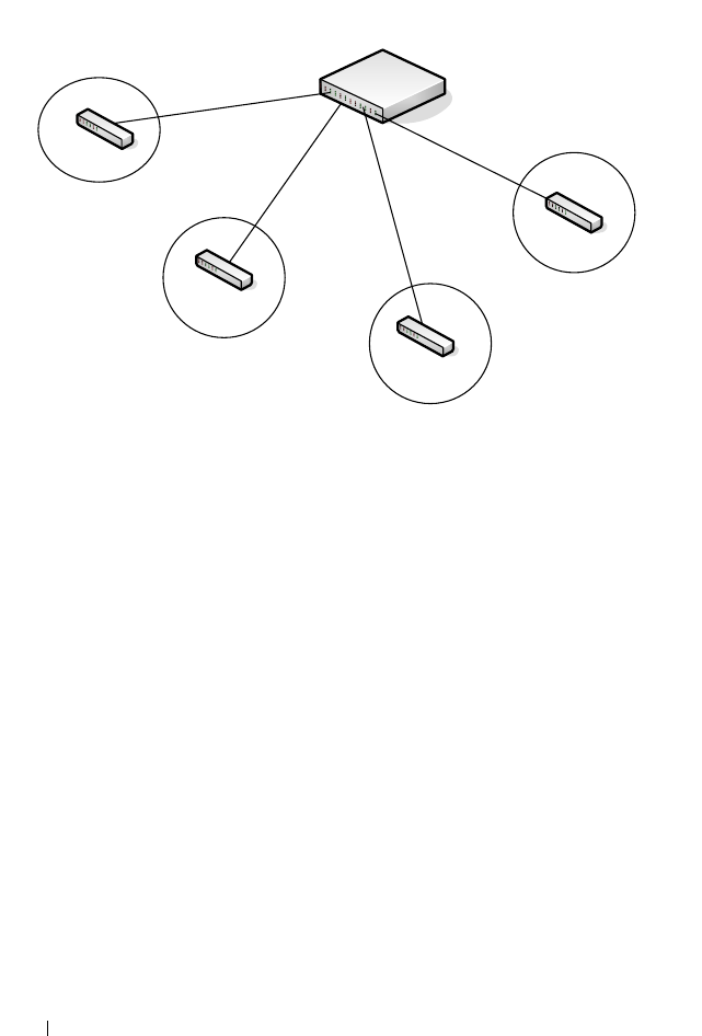
642 Configuring Access Control Lists
Figure 20-14. Policy Based Routing on VLAN Interfaces Example
Create VLANs 10, 20, 30 and 40
vlan 10,20,30,40
exit
Add VLAN Membership to Physical Ports
Also, configure the native VLAN on the corresponding interfaces:
interface gi1/0/2
switchport mode trunk
switchport trunk allowed vlan remove 1
switchport trunk native vlan 10
exit
interface gi 1/0/4
switchport mode trunk
swithport trunk allowed vlan remove 1
switchport trunk native vlan 20
exit
interface gi1/0/22
switchport mode trunk
switch trunk allowed vlan remove 1
switch trunk native vlan 30
exit
Layer 3 Switch
L2 Switch
L2 Switch
VLAN 10
VLAN 20
L2 Switch
VLAN 30
L2 Switch
VLAN 40
Physical Port 1/0/2
VLAN Interface 10
1.1.1.1/24
Physical Port 1/0/4
VLAN Interface 20
2.2.2.1/24 Physical Port 1/0/22
VLAN Interface 30
3.3.3.1/24
Physical Port 1/0/24
VLAN Interface 40
4.4.4.3/24

Configuring Access Control Lists 643
interface gi 1/0/24
switchport mode trunk
switchport trunk native vlan 40
switchport trunk allowed vlan remove 1
Enable Routing on Each VLAN Interface
interface vlan 10
ip address 1.1.1.1 255.255.255.0
exit
interface vlan 20
ip address 2.2.2.1 255.255.255.0
exit
interface vlan 30
ip address 3.3.3.1 255.255.255.0
exit
interface vlan 40
ip address 4.4.4.3 255.255.255.0
exit
Enable IP Routing (Global Configuration)
ip routing
In this configuration, traffic from host 1.1.1.2 to host 2.2.2.2 is routed from
VLAN routing interface 10 to VLAN routing interface 20 using the directly
connected subnets as they appear in the routing table.
Configure Policy Routing
To policy-route such traffic to VLAN routing interface 30, the following
additional steps should be performed:
1
Create an access-list matching all incoming IP traffic from host 1.1.1.1
destined to host 2.2.2.2:
ip access-list Match-ip-1_1_1_2-to-2_2_2_2
permit ip host 1.1.1.2 host 2.2.2.2
exit
There is no need to add a ’permit every’ rule, as would be configured in a
normal access list, as this ACL will only be used for PBR. The default for

644 Configuring Access Control Lists
PBR is to route non-matching traffic or traffic which is addressed to a non-
connected interface normally.
2
Create a route-map and add match/set rules to the route-map:
route-map Redirect_to_3_3_3_3 permit 100
match ip address Match-ip-1_1_1_2-to-2_2_2_2
set ip next-hop 3.3.3.3
exit
3
Assign the route-map to VLAN routing interface 10:
interface vlan 10
ip policy route-map Redirect_to_3_3_3_3
exit
Traffic matching ACL
Match-ip-1_1_1_2-to-2_2_2_2
is now policy-routed to
VLAN interface 30 when an interface in VLAN 30 is connected via policy
Redirect_to_3_3_3_3
. Counters are incremented in the “show route-map”
command indicating that traffic is being policy routed.
console(config)#show route-map Redirect_to_3_3_3_3
route-map "Redirect_to_3_3_3_3" permit 10
Match clauses:
ip address (access-lists) : match-subnet-1_1_1_X
Set clauses:
ip next-hop 3.3.3.3
Policy routing matches: 19922869 packets, 1275063872 bytes

Configuring VLANs 645
21
Configuring VLANs
This chapter describes how to configure VLANs, including port-based
VLANs, protocol-based VLANs, double-tagged VLANs, subnet-based VLANs,
and Voice VLANs.
The topics covered in this chapter include:
• VLAN Overview
• Default VLAN Behavior
• Configuring VLANs (Web)
• Configuring VLANs (CLI)
• VLAN Configuration Examples
VLAN Overview
By default, all switchports on a Dell Networking N2000, N3000, and N4000
series switches are in the same broadcast domain. This means when one host
connected to the switch broadcasts traffic, every device connected to the
switch receives that broadcast. All ports in a broadcast domain also forward
multicast and unknown unicast traffic to the connected host. Large broadcast
domains can result in network congestion, and end users might complain that
the network is slow. In addition to latency, large broadcast domains are a
greater security risk since all hosts receive all broadcasts.
Virtual Local Area Networks (VLANs) allow you to divide a broadcast domain
into smaller, logical networks. Like a bridge, a VLAN switch forwards traffic
based on the Layer 2 header, which is fast, and like a router, it partitions the
network into logical segments, which provides better administration, security,
and management of multicast traffic.
Network administrators have many reasons for creating logical divisions, such
as department or project membership. Because VLANs enable logical
groupings, members do not need to be physically connected to the same
switch or network segment. Some network administrators use VLANs to
segregate traffic by type so that the time-sensitive traffic, like voice traffic, has

646 Configuring VLANs
priority over other traffic, such as data. Administrators also use VLANs to
protect network resources. Traffic sent by authenticated clients might be
assigned to one VLAN, while traffic sent from unauthenticated clients might
be assigned to a different VLAN that allows limited network access.
When one host in a VLAN sends a broadcast, the switch forwards traffic only
to other members of that VLAN. For traffic to go from a host in one VLAN to
a host in a different VLAN, the traffic must be forwarded by a layer 3 device,
such as a router. VLANs work across multiple switches and switch stacks, so
there is no requirement for the hosts to be located near each other to
participate in the same VLAN.
Each VLAN has a unique number, called the VLAN ID. The Dell Networking
series switches support a configurable VLAN ID range of 1–4093. A VLAN
with VLAN ID 1 is configured on the switch by default. VLAN 1 is named
default
, which cannot be changed. However, you can associate names with
any other VLANs that you create.
In a tagged frame, the VLAN is identified by the VLAN ID in the tag. In an
untagged frame, the VLAN identifier is the Port VLAN ID (PVID) specified
for the port that received the frame. For information about tagged and
untagged frames, see "VLAN Tagging" on page 649.
The Dell Networking series switches support adding individual ports and Link
Aggregation Groups (LAGs) as VLAN members.
Figure 21-1 shows an example of a network with three VLANs that are
department-based. The file server and end stations for the department are all
members of the same VLAN.
NOTE: Dell Networking series switches support VLAN routing. When you
configure VLAN routing, the switch acts as a layer 3 device and can forward traffic
between VLANs. For more information, see "What Are VLAN Routing Interfaces?"
on page 1021.
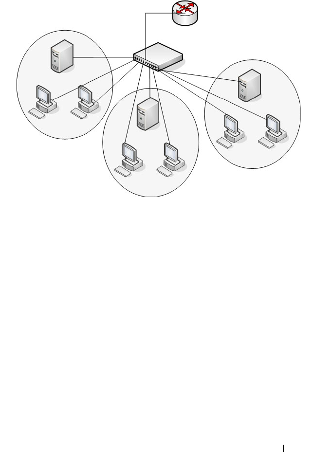
Configuring VLANs 647
Figure 21-1. Simple VLAN Topology
In this example, each port is manually configured so that the end station
attached to the port is a member of the VLAN configured for the port. The
VLAN membership for this network is port-based or static.
Dell Networking series switches also support VLAN assignment based on any
of the following criteria:
• MAC address of the end station
• IP subnet of the end station
• Protocol of the packet transmitted by the end station
Payroll
VLAN 300
Engineering
VLAN 100
Tech Pubs
VLAN 200
Router
Switch

648 Configuring VLANs
Table 21-1 provides an overview of the types of VLANs you can use to
logically divide the network.
Switchport Modes
You can configure each port on a Dell Networking N2000, N3000, and N4000
series switches to be in one of the following modes:
• Access — Access ports are intended to connect end-stations to the system,
especially when the end-stations are incapable of generating VLAN tags.
Access ports support a single VLAN (the PVID). Packets received untagged
are processed as if they are tagged with the access port PVID. Packets
received that are tagged with the PVID are also processed. Packets received
that are tagged with a VLAN other than the PVID are dropped. If the
VLAN associated with an access port is deleted, the PVID of the access
port is set to VLAN 1. VLAN 1 may not be deleted.
• Trunk — Trunk-mode ports are intended for switch-to-switch links. Trunk
ports can receive both tagged and untagged packets. Tagged packets
received on a trunk port are forwarded on the VLAN contained in the tag if
the trunk port is a member of the VLAN. Untagged packets received on a
Table 21-1. VLAN Assignment
VLAN Assignment Description
Port-based (Static) This is the most common way to assign hosts to VLANs.
The port where the traffic enters the switch determines the
VLAN membership.
IP Subnet Hosts are assigned to a VLAN based on their IP address. All
hosts in the same subnet are members of the same VLAN.
MAC-Based The MAC address of the device determines the VLAN
assignment. This type of VLAN is useful when a host
might not always connect to the network through the same
port but needs to be on the same VLAN.
Protocol Protocol-based VLANs were developed to separate traffic
based on the protocol type before IP traffic became the de
facto standard in the LAN. Use a protocol-based VLAN on
networks where you might have a group of hosts that use
IPX or another legacy protocol. With protocol-based
VLANs, you can segregate traffic based on the EtherType
value in the frame.

Configuring VLANs 649
trunk port are forwarded on the native VLAN. Packets received on another
interface belonging to the native VLAN are transmitted untagged on a
trunk port.
• General — General ports can act like access or trunk ports or a hybrid of
both.
VLAN membership rules that apply to a port are based on the switchport
mode configured for the port. Table 21-2 shows the behavior of the three
switchport modes.
When a port is in General mode, all VLAN features are configurable. When
ingress filtering is on, the frame is dropped if the port is not a member of the
VLAN identified by the VLAN ID in the tag. If ingress filtering is off, all
tagged frames are forwarded. The port decides whether to forward or drop the
frame when the port receives the frame.
VLAN Tagging
Dell Networking series switches support IEEE 802.1Q tagging. Ethernet
frames on a tagged VLAN have a 4-byte VLAN tag in the header. VLAN
tagging is required when a VLAN spans multiple switches, which is why trunk
ports transmit and receive only tagged frames.
Table 21-2. Switchport Mode Behavior
Mode VLAN Membership Frames
Accepted
Frames Sent Ingress
Filtering
Access One VLAN Untagged/
Tagged
Untagged Always On
Trunk All VLANs that exist in
the system (default)
Untagged/
Tagged
Tagg ed a n d
Untagged
Always On
General As many as desired Tagged or
Untagged
Tagg ed o r
Untagged
On or Off
NOTE: A stack of switches behaves as a single switch, so VLAN tagging is not
required for packets traversing different stack members.

650 Configuring VLANs
Tagging may be required when a single port supports multiple devices that are
members of different VLANs. For example, a single port might be connected
to an IP phone, a PC, and a printer (the PC and printer are connected via
ports on the IP phone). IP phones are typically configured to use a tagged
VLAN for voice traffic, while the PC and printers typically use the untagged
VLAN.
Trunk ports can receive tagged and untagged traffic. Untagged traffic is
tagged internally with the native VLAN. Native VLAN traffic received
untagged is transmitted untagged on a trunk port.
By default, trunk ports are members of all existing VLANs and will
automatically participate in any newly created VLANs. The administrator can
restrict the VLAN membership of a trunk port. VLAN membership for tagged
frames received on a trunk port is configured separately from the membership
of the native VLAN. To configure a trunk port to accept frames only for a
single VLAN, both the native VLAN and the tagged VLAN membership
settings must be configured. If the native VLAN for a trunk port is deleted,
the trunk port drops untagged packets.
Access ports accept untagged traffic and traffic tagged with the access port
PVID. Untagged ingress traffic is considered to belong to the VLAN
identified by the PVID. If the PVID for an access port is deleted, the PVID is
set to VLAN 1.
GVRP
The GARP VLAN Registration Protocol (GVRP) helps to dynamically
manage VLAN memberships on trunk ports. When GARP is enabled,
switches can dynamically register (and de-register) VLAN membership
information with other switches attached to the same segment.
Information about the active VLANs is propagated across all networking
switches in the bridged LAN that support GVRP. You can configure ports to
forbid dynamic VLAN assignment through GVRP.
The operation of GVRP relies upon the services provided by the Generic
Attribute Registration Protocol (GARP). GVRP can create up to 1024 VLANs.
For information about GARP timers, see "What Are GARP and GMRP?" on
page 810.

Configuring VLANs 651
Double-VLAN Tagging
For trunk ports, which are ports that connect one switch to another switch,
the Dell Networking series switches support double-VLAN tagging. This
feature allows service providers to create Virtual Metropolitan Area Networks
(VMANs). With double-VLAN tagging, service providers can pass VLAN
traffic from one customer domain to another through a metro core in a
simple and cost-effective manner. By using an additional tag on the traffic,
the switch can differentiate between customers in the MAN while preserving
an individual customer’s VLAN identification when the traffic enters the
customer’s 802.1Q domain.
With the introduction of this second tag, customers are no longer required to
divide the 4-byte VLAN ID space to send traffic on a Ethernet-based MAN.
In short, every frame that is transmitted from an interface has a double-VLAN
tag attached, while every packet that is received from an interface has a tag
removed (if one or more tags are present).
In Figure 21-2, two customers share the same metro core. The service
provider assigns each customer a unique ID so that the provider can
distinguish between the two customers and apply different rules to each.
When the configurable EtherType is assigned to something different than the
802.1Q (0x8100) EtherType, it allows the traffic to have added security from
misconfiguration while exiting the metro core. For example, if the edge
device on the other side of the metro core is not stripping the second tag, the
packet would never be classified as a 802.1Q tag, so the packet would be
dropped rather than forwarded in the incorrect VLAN.
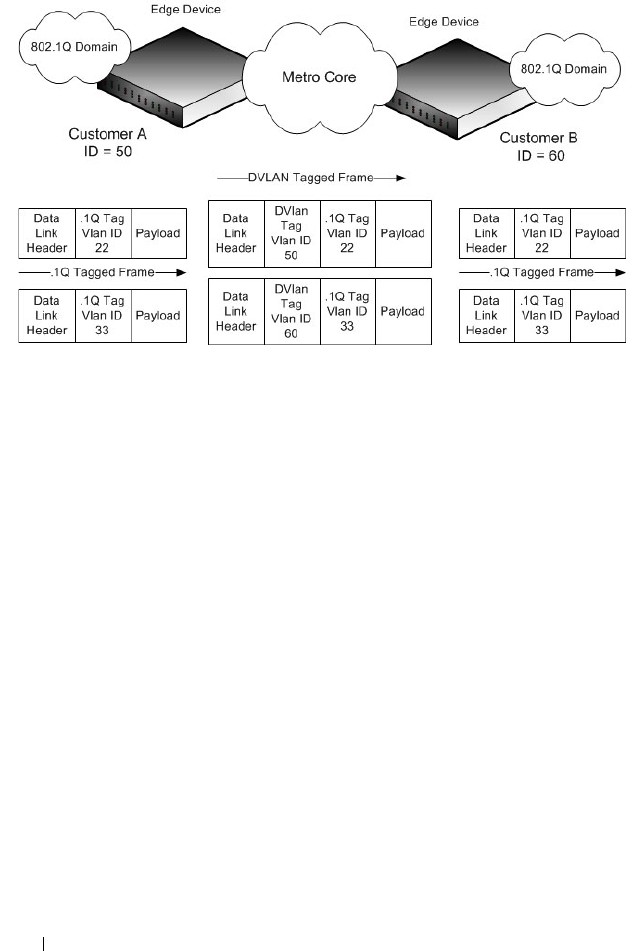
652 Configuring VLANs
Figure 21-2. Double VLAN Tagging Network Example
Voice VLAN
The Voice VLAN feature enables switch ports to carry voice traffic with
defined priority. When multiple devices, such as a PC and an IP phone, are
connected to the same port, you can configure the port to use one VLAN for
voice traffic and another VLAN for data traffic.
Voice over IP (VoIP) traffic is inherently time-sensitive: for a network to
provide acceptable service, the transmission rate is vital. The priority level
enables the separation of voice and data traffic coming onto the port.
A primary benefit of using Voice VLAN is to ensure that the sound quality of
an IP phone is safeguarded from deteriorating when the data traffic on the
port is high. The switch uses the source MAC address of the traffic traveling
through the port to identify the IP phone data flow.
The Voice VLAN feature can be enabled on a per-port basis. This feature
supports a configurable voice VLAN DSCP value. This value is later retrieved
by LLDP when the LLDPDU is transmitted, if LLDP has been enabled on
the port and the required TLV is configured for the port.

Configuring VLANs 653
Identifying Voice Traffic
Some VoIP phones contain full support for IEEE 802.1X. When these phones
are connected to a port that uses 802.1X port-based authentication, these
phones authenticate and receive their VLAN information from LLDP-MED.
However, if a VoIP phone has limited support for 802.1X authentication it
might try to authenticate and fail. A phone with no 802.1X support would not
attempt to authenticate at all. Instead of placing these phones on an
unauthenticated or guest VLAN, the switch can automatically direct the VoIP
traffic to the Voice VLAN without manual configuration.
The switch identifies the device as a VoIP phone by one of the following
protocols:
• Cisco Discovery Protocol (CDP) or Industry Standard Discovery Protocol
(ISDP) for Cisco VoIP phones
• DHCP vendor-specific options for Avaya VoIP phones
• LLDP-MED for most VoIP phones
After the VoIP phone receives its VLAN information, all traffic is tagged with
the VLAN ID of the Voice VLAN. The phone is considered to be authorized
to send traffic but not necessarily authenticated.
Segregating Traffic with the Voice VLAN
You can configure the switch to support Voice VLAN on a port that is
connecting the VoIP phone. Both of the following methods segregate the
voice traffic and the data traffic in order to provide better service to the voice
traffic.
• When a VLAN is associated with the Voice VLAN port, then the VLAN ID
information is passed onto the VoIP phone using either the LLDP-MED or
the CPD mechanism, depending on how the phone is identified: if it is
identified via CDP, then the VLAN assignment is via CDP and if it is
identified via LLDP-MED, then the VLAN assignment is via LLDP-MED.
By this method, the voice data coming from the VoIP phone is tagged with
the exchanged VLAN ID. Untagged data arriving on the switch is given the
NOTE: By default, ISDP is enabled globally and per-interface on the switch.
LLDP-MED is disabled on each interface by default. Port-based authentication
using 802.1X is also disabled on each port by default.

654 Configuring VLANs
default PVID of the port, and the voice traffic is received tagged with the
predefined VLAN. As a result, both kinds of traffic are segregated in order
to provide better service to the voice traffic.
• When a dot1p priority is associated with the Voice VLAN port instead of a
VLAN ID, then the priority information is passed onto the VoIP phone
using the LLDP-MED or CDP mechanism. By this method, the voice data
coming from the VoIP phone is tagged with VLAN 0 and with the
exchanged priority; thus regular data arriving on the switch is given the
default priority of the port (default 0), and the voice traffic is received with
a higher priority.
You can configure the switch to override the data traffic CoS. This feature can
override the 802.1 priority of the data traffic packets arriving at the port
enabled for Voice VLAN. Therefore, any rogue client that is also connected to
the Voice VLAN port does not deteriorate the voice traffic.
Voice VLAN and LLDP-MED
The interactions with LLDP-MED are important for Voice VLAN:
• LLDP-MED notifies the Voice VLAN component of the presence and
absence of a VoIP phone on the network.
• The Voice VLAN component interacts with LLDP-MED for applying
VLAN ID, priority, and tag information to the VoIP phone traffic.
Private VLANs
Private VLANs partition a standard VLAN domain into two or more
subdomains. Each subdomain is defined by a primary VLAN and a secondary
VLAN. The primary VLAN ID is the same for all subdomains that belong to a
particular private VLAN instance. The secondary VLAN ID differentiates the
subdomains from each other and provides layer 2 isolation between ports on
the same private VLAN.
The following types of VLANs can be configured in a private VLAN:
•
Primary VLAN
—Forwards the traffic from the promiscuous ports to
isolated ports, community ports and other promiscuous ports in the same
private VLAN. Only one primary VLAN can be configured per private
VLAN. All ports within a private VLAN share the same primary VLAN.

Configuring VLANs 655
•
Isolated VLAN
—A secondary VLAN. It carries traffic from isolated ports
to promiscuous ports. Only one isolated VLAN can be configured per
private VLAN.
•
Community VLAN
—A secondary VLAN. It forwards traffic between ports
which belong to the same community and to the promiscuous ports. There
can be multiple community VLANs per private VLAN.
A port may be designated as one of the following types in a private VLAN:
•
Promiscuous port
—A port associated with a primary VLAN that is able to
communicate with all interfaces in the private VLAN, including other
promiscuous ports, community ports and isolated ports.
•
Host port
—A port associated with a secondary VLAN that can either
communicate with the promiscuous ports in the VLAN and with other
ports in the same community (if the secondary VLAN is a community
VLAN) or can communicate only with the promiscuous ports (if the
secondary VLAN is an isolated VLAN).
Private VLANs may be configured across a stack and on physical and port-
channel interfaces.
Private VLAN Usage Scenarios
Private VLANs are typically implemented in a DMZ for security reasons.
Servers in a DMZ are generally not allowed to communicate with each other
but they must communicate to a router, through which they are connected to
the users. Such servers are connected to host ports, and the routers are
attached to promiscuous ports. Then, if one of the servers is compromised,
the intruder cannot use it to attack another server in the same network
segment.
The same traffic isolation can be achieved by assigning each port with a
different VLAN, allocating an IP subnet for each VLAN, and enabling layer 3
routing between them. In a private VLAN domain, on the other hand, all
members can share the common address space of a single subnet, which is
associated with a primary VLAN. So, the advantage of the private VLANs
feature is that it reduces the number of consumed VLANs, improves IP
addressing space utilization, and helps to avoid layer 3 routing.
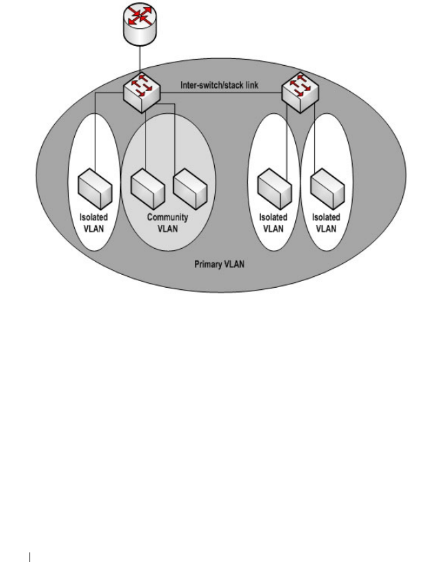
656 Configuring VLANs
Figure 21-3 shows an example Private VLAN scenario, in which five hosts (H-
A through H-E) are connected to a stack of switches (SW1, SW2). The
switch stack is connected to router R1. Port references shown are with
reference to the stack.
Figure 21-3. Private VLAN Domain
Promiscuous Ports
An endpoint connected to a promiscuous port is allowed to communicate
with any endpoint within the private VLAN. Multiple promiscuous ports can
be defined for a single private VLAN domain.
In the configuration shown in Figure 21-3, the port connected from SW1 to
R1 (TE1/1/1) is configured as a promiscuous port. It is possible to configure a
port-channel as a promiscuous port in order to provide a level of redundancy
on the private VLAN uplink.
R1
TE1/1/1
SW1
Gi1/0/10 Gi1/0/11
Gi1/0/12
H-A H-B H-C H-D H-E
Gi2/0/10 Gi2/0/11
SW2

Configuring VLANs 657
Isolated Ports
An endpoint connected to an isolated port is allowed to communicate with
endpoints connected to promiscuous ports only. Endpoints connected to
adjacent isolated ports cannot communicate with each other.
Community Ports
An endpoint connected to a community port is allowed to communicate with
the endpoints within a community and can also communicate with any
configured promiscuous port. The endpoints that belong to one community
cannot communicate with endpoints that belong to a different community, or
with endpoints connected to isolated ports.
Private VLAN Operation in the Switch Stack and Inter-switch Environment
The Private VLAN feature is supported in a stacked switch environment. The
stack links are transparent to the configured VLANs; thus, there is no need for
special private VLAN configuration beyond what would be configured for a
single switch. Any private VLAN port can reside on any stack member.
To enable private VLAN operation across multiple switches that are not
stacked, trunk ports must be configured between the switches to transport
the private VLANs. The trunk ports must be configured with the
promiscuous, isolated, and community VLANs. Trunk ports must also be
configured on all devices separating the switches.
In regular VLANs, ports in the same VLAN switch traffic at L2. However, for a
private VLAN, the promiscuous port forwards received traffic to secondary
ports in the VLAN (isolated and community). Community ports forward
received traffic to the promiscuous ports and other community ports using
the same secondary VLAN. Isolated ports transmit received traffic to the
promiscuous ports only.
The ports to which the broadcast traffic is forwarded depend on the type of
port on which the traffic was received. If the received port is a host port,
traffic is broadcast to all promiscuous and trunk ports. If the received port is a
community port, the broadcast traffic is forwarded to all promiscuous, trunk,
and community ports in the same secondary VLAN. A promiscuous port
broadcasts traffic to other promiscuous ports, isolated ports, and community
ports.

658 Configuring VLANs
Table 21-3. Forwarding Rules for Traffic in Primary VLAN
Table 21-4. Forwarding Rules for Traffic in Community 1 VLAN
Table 21-5. Forwarding Rules for Traffic in Isolated VLAN
To
From promiscuous community 1 community 2 isolated stack (trunk)
promiscuous allow allow allow allow allow
community 1 N/A N/A N/A N/A N/A
community 2 N/A N/A N/A N/A N/A
isolatedN/AN/AN/AN/AN/A
stack (trunk) allow allow allow allow allow
To
From promiscuous community 1 community 2 isolated stack (trunk)
promiscuous N/A N/A N/A N/A N/A
community 1 allow allow deny deny allow
community 2 N/A N/A N/A N/A N/A
isolatedN/AN/AN/AN/AN/A
stack (trunk) allow allow deny deny allow
To
From promiscuous community 1 community 2 isolated stack (trunk)
promiscuous N/A N/A N/A N/A N/A
community 1 N/A N/A N/A N/A N/A
community 2 N/A N/A N/A N/A N/A
isolated allowdenydenydenyallow
stack (trunk)allowdenydenydenyAllow

Configuring VLANs 659
Limitations and Recommendations
• Only a single isolated VLAN can be associated with a primary VLAN.
Multiple community VLANs can be associated with a primary VLAN.
• Trunk and general modes are not supported on private VLAN ports.
• Do not configure access ports using the VLANs participating in any of the
private VLANs.
• Multiple primary VLANs may be configured. Each primary VLAN must be
unique and each defines a separate private VLAN domain. The operator
must take care to use only the secondary VLANs associated with the
primary VLAN of a domain.
• Private VLANs cannot be enabled on a preconfigured interface. The
interface must physically exist in the switch.
• Secondary (community and isolated) VLANS are associated to the same
multiple spanning tree instance as the primary VLAN.
• GVRP/MVRP cannot be enabled after the private VLAN is configured.
The administrator will need to disable both before configuring the private
VLAN.
• DHCP snooping can be configured on the primary VLAN. If it is enabled
for a secondary VLAN, the configuration does not take effect if a primary
VLAN is already configured.
• If IP source guard is enabled on private VLAN ports, then DHCP snooping
must be enabled on the primary VLAN.
• Do not configure private VLAN ports on interfaces configured for voice
VLAN.
• If static MAC addresses are added for the host port, the same static MAC
address entry must be added to the associated primary VLAN. This does
not need to be replicated for dynamic MAC addresses.
• A private VLAN cannot be enabled on a management VLAN.
• A private VLAN cannot be enabled on the default VLAN.
• VLAN routing can be enabled on private VLANs. It is not very useful to
enable routing on secondary VLANs, as the access to them is restricted.
However, primary VLANs can be enabled for routing.

660 Configuring VLANs
• It is recommended that the private VLAN IDs be removed from the trunk
ports connected to devices that do not participate in the private VLAN
traffic.
Private VLAN Configuration Example
See "Configuring a Private VLAN" on page 711.
Additional VLAN Features
The Dell Networking series switches also support the following VLANs and
VLAN-related features:
• VLAN routing interfaces — See "Configuring Routing Interfaces" on
page 1021.
• Guest VLAN — See "Configuring Port and System Security" on page 503.

Configuring VLANs 661
Default VLAN Behavior
One VLAN is configured on the Dell Networking series switches by default.
The VLAN ID is 1, and all ports are included in the VLAN as access ports,
which are untagged. This means when a device connects to any port on the
switch, the port forwards the packets without inserting a VLAN tag. If a
device sends a tagged frame to a port with a VLAN ID other than 1, the frame
is dropped. Since all ports are members of this VLAN, all ports are in the same
broadcast domain and receive all broadcast and multicast traffic received on
any port.
When you create a new VLAN, all trunk ports are members of the VLAN by
default. The configurable VLAN range is 2–4093. VLANs 4094 and 4095 are
reserved for internal system use.
Ports in trunk and access mode have the default behavior shown in Table 21-2
and cannot be configured with different tagging or ingress filtering values.
When you add a VLAN to a port in general mode, the VLAN has the behavior
shown in Table 21-6.
Table 21-6. General mode Default Settings
Feature Default Value
Frames accepted Untagged
Incoming untagged frames are classified into the VLAN
whose VLAN ID is the currently configured PVID.
Frames sent Untagged
Ingress Filtering On
PVID 1

662 Configuring VLANs
Table 21-7 shows the default values or maximum values for VLAN features.
Table 21-7. Additional VLAN Default and Maximum Values
Feature Value
Default VLAN VLAN 1
VLAN Name No VLAN name is configured except for VLAN 1,
whose name “default” cannot be changed.
VLAN Range 2–4093
Switchport mode Access
Double-VLAN tagging Disabled
If double-VLAN tagging is enabled, the default
EtherType value is 802.1Q
Maximum number of
configurable MAC-to-VLAN
bindings
128
Maximum number of
configurable
IP Subnet-to-VLAN bindings
64
GVRP Disabled
If GVRP is enabled, the default per-port parameters
are:
•GVRP State: Disabled
• Dynamic VLAN Creation: Enabled
•GVRP Registration: Enabled
Number of dynamic VLANs
that can be assigned through
GVRP
1024
Voice VLAN Disabled
Voice VLAN DSCP value 46
Voice VLAN authentication
mode
Enabled

Configuring VLANs 663
Configuring VLANs (Web)
This section provides information about the OpenManage Switch
Administrator pages for configuring and monitoring VLANs on a Dell
Networking N2000, N3000, and N4000 series switches. For details about the
fields on a page, click at the top of the page.
VLAN Membership
Use the VLAN Membership page to create VLANs and define VLAN groups
stored in the VLAN membership table.
To display the VLAN Membership page, click Switching
→
VLAN
→
VLAN
Membership in the navigation panel.
The VLAN Membership tables display which Ports and LAGs are members of
the VLAN, and whether they’re tagged (T), untagged (U), or forbidden (F).
The tables have two rows: Static and Current. Only the Static row is
configurable. The Current row is updated either dynamically through GVRP
or when the Static row is changed and Apply is clicked.
There are two tables on the page:
•
Ports
— Displays and assigns VLAN membership to ports. To assign
membership, click in
Static
for a specific port. Each click toggles between
U, T, and blank. See
Tab le 21-8
for definitions.
•
LAGs
— Displays and assigns VLAN membership to LAGs. To assign
membership, click in
Static
for a specific LAG. Each click toggles between
U, T, and blank. See
Tab le 21-8
for definitions.
Table 21-8. VLAN Port Membership Definitions
Port Control Definition
T Tagged: the interface is a member of a VLAN. All packets forwarded by
the interface in this VLAN are tagged. The packets contain VLAN
information.
U Untagged: the interface is a VLAN member. Packets forwarded by the
interface in this VLAN are untagged.
F Forbidden: indicates that the interface is forbidden from becoming a
member of the VLAN. This setting is primarily for GVRP, which
enables dynamic VLAN assignment.

664 Configuring VLANs
To perform additional port configuration, such as making the port a trunk
port, use the Port Settings page.
Figure 21-4. VLAN Membership
Adding a VLAN
To create a VLAN:
1
Open the
VLAN Membership
page.
2
Click
Add
to display the
Add VLAN
page.
3
Specify a VLAN ID and a VLAN name.
Blank Blank: the interface is not a VLAN member. Packets in this VLAN are
not forwarded on this interface.
Table 21-8. VLAN Port Membership Definitions
Port Control Definition
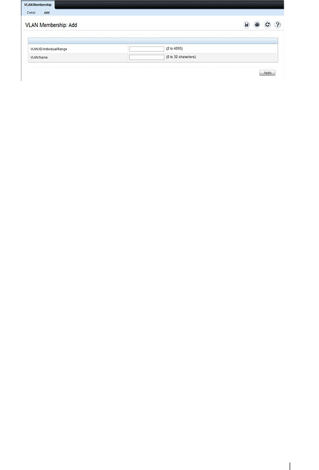
Configuring VLANs 665
Figure 21-5. Add VLAN
4
Click
Apply
.
Configuring Ports as VLAN Members
To add member ports to a VLAN:
1
Open the
VLAN Membership
page.
2
From the
Show VLAN
menu, select the VLAN to which you want to assign
ports.
3
In the
Static
row of the
VLAN Membership
table, click the blank field to
assign the port as an untagged member.
Figure 21-6 shows 10-Gigabit Ethernet ports 8–10 being added to VLAN
300.
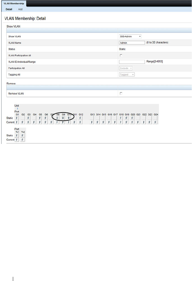
666 Configuring VLANs
Figure 21-6. Add Ports to VLAN
4
Click
Apply
.
5
Verify that the ports have been added to the VLAN.

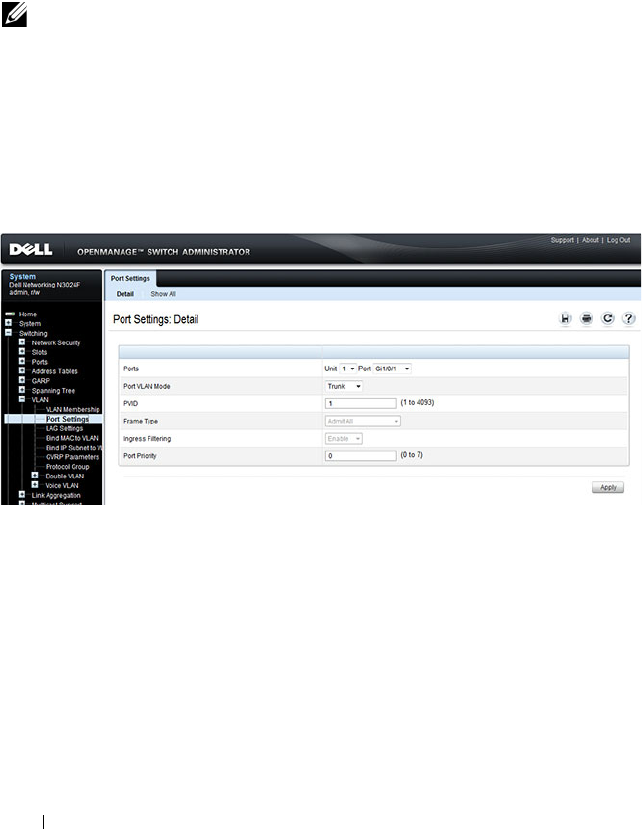
668 Configuring VLANs
VLAN Port Settings
Use the VLAN Port Settings page to add ports to an existing VLAN and to
configure settings for the port. If you select Trunk or Access as the Port VLAN
Mode, some of the fields are not configurable because of the requirements for
that mode.
To display the Port Settings page, click Switching
→
VLAN
→
Port Settings
in the navigation panel.
Figure 21-8. VLAN Port Settings
From the Port Settings page, click Show All to see the current VLAN settings
for all ports. You can change the settings for one or more ports by clicking the
Edit option for a port and selecting or entering new values.
NOTE: You can add ports to a VLAN through the table on the VLAN Membership
page or through the PVID field on the Port Settings page. The PVID is the VLAN
that untagged received packets are assigned to. To include a general-mode port
in multiple VLANs, use the VLAN Membership page.
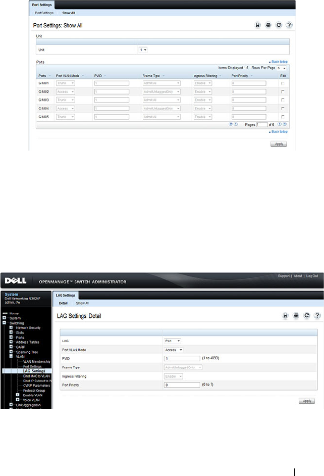
Configuring VLANs 669
Figure 21-9. VLAN Settings for All Ports
VLAN LAG Settings
Use the VLAN LAG Settings page to map a LAG to a VLAN and to configure
specific VLAN settings for the LAG.
To display the LAG Settings page, click Switching
→
VLAN
→
LAG Settings
in the navigation panel.
Figure 21-10. VLAN LAG Settings
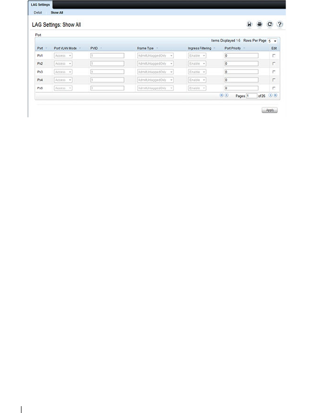
670 Configuring VLANs
From the LAG Settings page, click Show All to see the current VLAN settings
for all LAGs. You can change the settings for one or more LAGs by clicking
the Edit option for a port and selecting or entering new values.
Figure 21-11. VLAN LAG Table
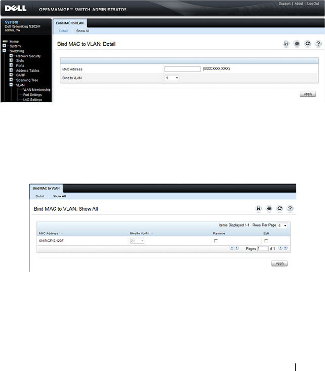
Configuring VLANs 671
Bind MAC to VLAN
Use the Bind MAC to VLAN page to map a MAC address to a VLAN. After
the source MAC address and the VLAN ID are specified, the MAC to VLAN
configurations are shared across all ports of the switch. The MAC to VLAN
table supports up to 128 entries.
To display the Bind MAC to VLAN page, click Switching
→
VLAN
→
Bind
MAC to VLAN in the navigation panel.
Figure 21-12. Bind MAC to VLAN
From the Bind MAC to VLAN page, click Show All to see the MAC
addresses that are mapped to VLANs. From this page, you can change the
settings for one or more entries or remove an entry.
Figure 21-13. MAC-VLAN Bind Table
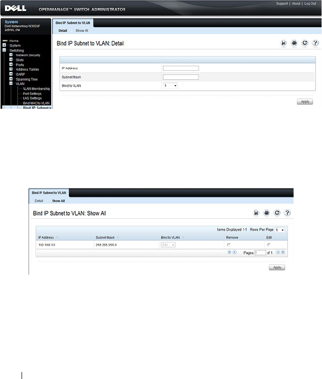
672 Configuring VLANs
Bind IP Subnet to VLAN
Use the Bind IP Subnet to VLAN page to assign an IP Subnet to a VLAN.
The IP Subnet to VLAN configurations are shared across all ports of the
switch. There can be up to 64 entries configured in this table.
To display the Bind IP Subnet to VLAN page, click Switching
→
VLAN
→
Bind IP Subnet to VLAN in the navigation panel.
Figure 21-14. Bind IP Subnet to VLAN
From the Bind IP Subnet to VLAN page, click Show All to see the IP subnets
that are mapped to VLANs. From this page, you can change the settings for
one or more entries or remove an entry.
Figure 21-15. Subnet-VLAN Bind Table
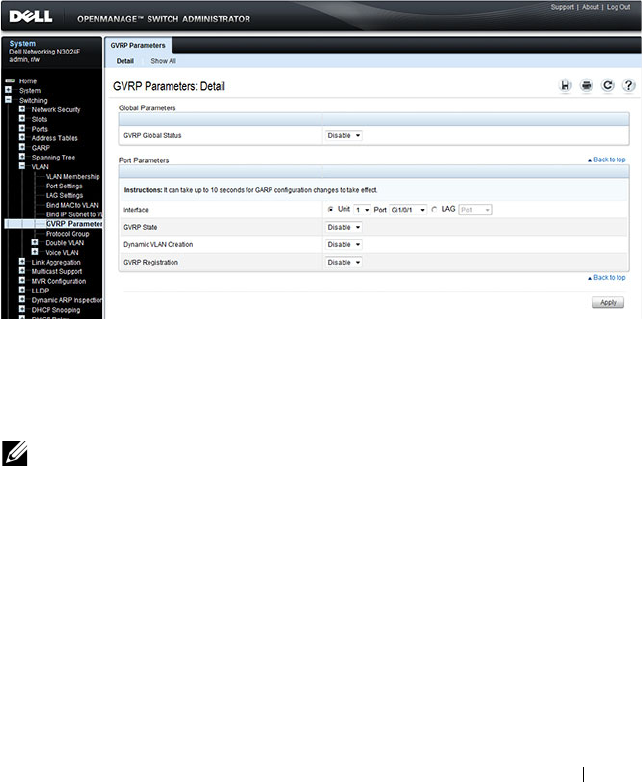
Configuring VLANs 673
GVRP Parameters
Use the GVRP Parameters page to enable GVRP globally and configure the
port settings.
To display the GVRP Parameters page, click Switching
→
VLAN
→
GVRP
Parameters in the navigation panel.
Figure 21-16. GVRP Parameters
From the GVRP Parameters page, click Show All to see the GVRP
configuration for all ports. From this page, you can change the settings for
one or more entries.
NOTE: Per-port and per-LAG GVRP Statistics are available from the
Statistics/RMON page. For more information, see "Monitoring Switch Traffic" on
page 407.
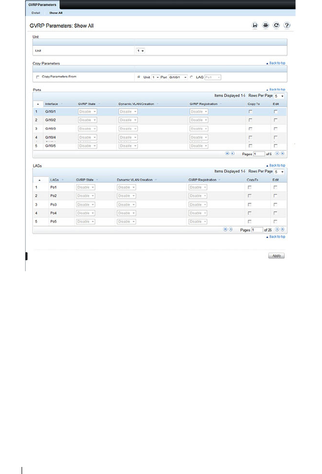
674 Configuring VLANs
Figure 21-17. GVRP Port Parameters Table
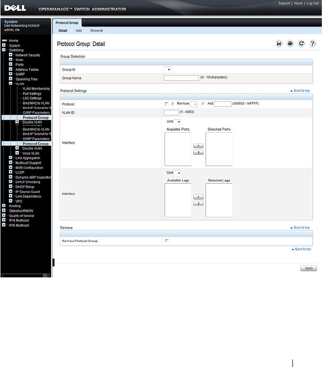
Configuring VLANs 675
Protocol Group
Use the Protocol Group page to configure which EtherTypes go to which
VLANs, and then enable certain ports to use these settings. Protocol-based
VLANs are most often used in situations where network segments contain
hosts running multiple protocols.
To display the Protocol Group page, click Switching
→
VLAN
→
Protocol
Group in the navigation panel.
Figure 21-18. Protocol Group
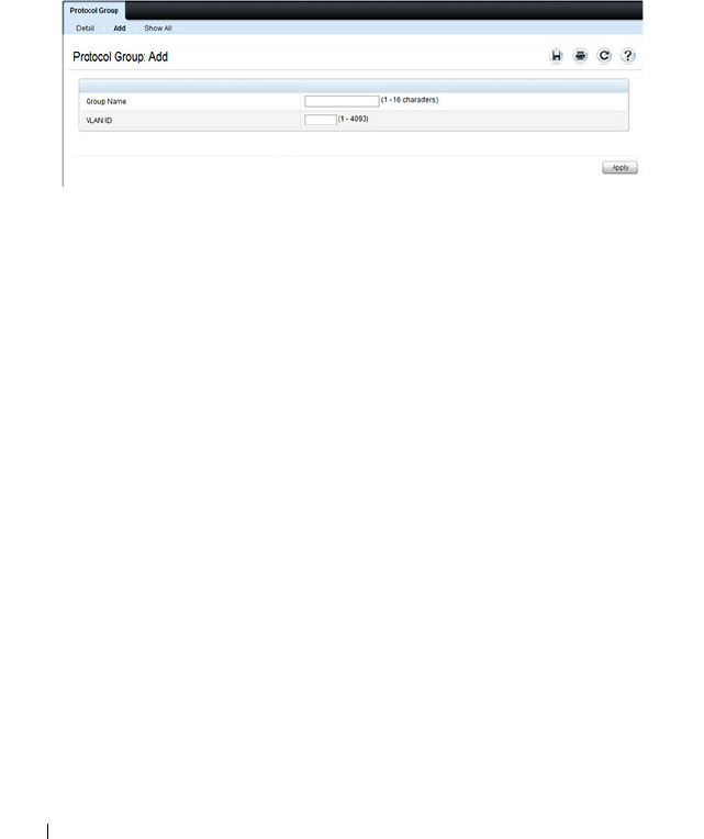
676 Configuring VLANs
Adding a Protocol Group
To add a protocol group:
1
Open the
Protocol Group page.
2
Click
Add
to display the
Add
Protocol Group
page.
3
Create a name for the group and associate a VLAN with the group.
Figure 21-19. Add Protocol Group
4
Click
Apply
.
5
Click
Protocol Group
to return to the main
Protocol Group
page.
6
From the
Group ID
field, select the group to configure.
7
In the
Protocol Settings
table, select the protocol and interfaces to
associate with the protocol-based VLAN.
In Figure 21-20, the Protocol Group 1 (named IPX) is associated with the
IPX protocol and ports 14–16. Ports 20-22 are selected in
Available Ports
list. After clicking the right arrow, they will be added to the
Selected Ports
list.
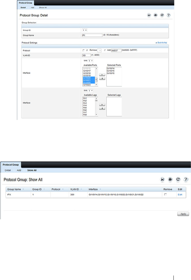
Configuring VLANs 677
Figure 21-20. Configure Protocol Group
8
Click
Apply
.
9
Click
Show All
to see the protocol-based VLANs and their members.
Figure 21-21. Protocol Group Table
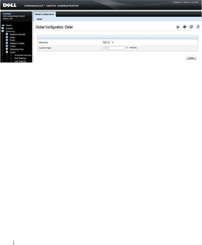
678 Configuring VLANs
Double VLAN Global Configuration
Use the Double VLAN Global Configuration page to specify the value of the
EtherType field in the first EtherType/tag pair of the double-tagged frame.
To display the Double VLAN Global Configuration page, click Switching
→
VLAN
→
Double VLAN
→
Global Configuration in the navigation panel.
Figure 21-22. Double VLAN Global Configuration
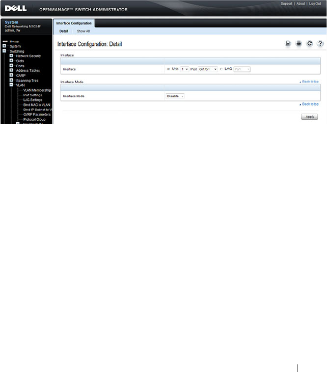
Configuring VLANs 679
Double VLAN Interface Configuration
Use the Double VLAN Interface Configuration page to specify the value of
the EtherType field in the first EtherType/tag pair of the double-tagged
frame.
To display the Double VLAN Interface Configuration page, click Switching
→
VLAN
→
Double VLAN
→
Interface Configuration in the navigation
panel.
Figure 21-23. Double VLAN Interface Configuration
To view a summary of the double VLAN configuration for all interfaces and to
edit settings for one or more interfaces, click Show All.
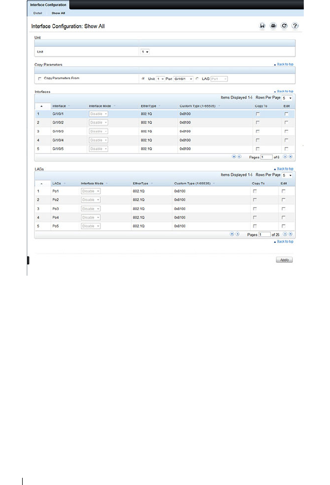
680 Configuring VLANs
Figure 21-24. Double VLAN Port Parameter Table
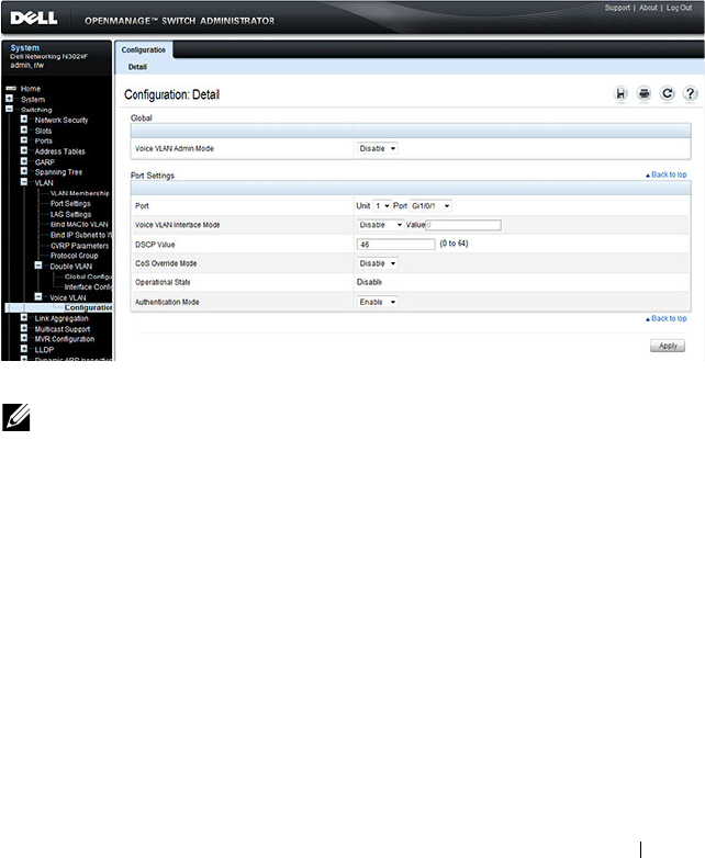
Configuring VLANs 681
Voice VLAN
Use the Voice VLAN Configuration
page to configure and view voice VLAN
settings that apply to the entire system and to specific interfaces.
To display the page, click Switching
→
VLAN
→
Voice VLAN
→
Configuration
in the
navigation panel
.
Figure 21-25. Voice VLAN Configuration
NOTE: IEEE 802.1X must be enabled on the switch before you disable voice
VLAN authentication. Voice VLAN authentication can be disabled in order to
allow VoIP phones that do not support authentication to send and receive
unauthenticated traffic on the Voice VLAN.

682 Configuring VLANs
Configuring VLANs (CLI)
This section provides information about the commands you use to create and
configure VLANs. For more information about the commands, see the
Dell
Networking N2000, N3000, and N4000 Series Switches CLI Reference Guide
at support.dell.com/manuals.
Creating a VLAN
Beginning in Privileged EXEC mode, use the following commands to
configure a VLAN and associate a name with the VLAN.
Configuring a Port in Access Mode
Beginning in Privileged EXEC mode, use the following commands to
configure an access mode VLAN interface and, optionally, assign the interface
to a VLAN. When a port is in access mode, it can only be a member of one
VLAN and will accept tagged packets with the access VLAN ID or untagged
Command Purpose
configure Enter global configuration mode.
vlan {
vlan-id
|
vlan-
range
}
Create a new VLAN or a range of VLANs and enter the
interface configuration mode for the specified VLAN or
VLAN range.
•
vlan-id
—A valid VLAN IDs (Range: 2–4093).
•
vlan-range
— A list of valid VLAN IDs to be added. List
separate, non-consecutive VLAN IDs separated by
commas (without spaces); use a hyphen to designate a
range of IDs. (Range: 2–4093)
name
string
Add a name to the specified VLAN.
string
— Comment or description to help identify a
specific VLAN (Range: 1–32 characters).
CTRL + Z Exit to Privileged EXEC mode.
show vlan [id
vlan-id
|
name
vlan-name
]
Display VLAN information.
•
vlan-id
— A valid VLAN ID.
(Range: 1–4093)
•
vlan-name
— A valid VLAN name string. (Range: 1–32
characters)

Configuring VLANs 683
packets. Untagged packets are treated as belonging to the access VLAN.
Packets received with a VLAN ID other than the access VLAN ID are
discarded. When you configure an interface as an access mode port, the
interface is automatically made a member of VLAN 1 and removed from all
other VLAN memberships. You can configure each interface separately, or you
can configure a range of interfaces with the same settings.
Configuring a Port in Trunk Mode
Beginning in Privileged EXEC mode, use the following commands to
configure an interface as a layer 2 trunking interface, which connects two
switches. Trunk mode ports support traffic tagged with different VLAN IDs.
Untagged received traffic is switched in the native VLAN. A trunk port is
Command Purpose
configure Enter global configuration mode.
interface
interface
Enter interface configuration mode for the specified
interface. The
interface
variable includes the interface type
and number, for example tengigabitethernet 1/0/3.
You can also specify a range of interfaces with the interface
range command, for example, interface range
tengigabitethernet 1/0/8-12 configures interfaces 8, 9, 10,
11, and 12.
switchport mode access Configure the interface as an access mode VLAN interface.
Access mode VLANs accept tagged or untagged packets for
the access VLAN only.
switchport access vlan
vlan-id
Configure the interface as a member of the specified
VLAN. By default, access mode ports are members of
VLAN 1.
vlan-id
— A valid VLAN ID of the VLAN to which the port
is configured. (Range: 1–4093)
CTRL + Z Exit to Privileged EXEC mode.
show interfaces
switchport
interface
Display information about the VLAN settings configured
for the specified interface.

684 Configuring VLANs
automatically configured as a member of all VLANs. You can remove them
from membership in specific VLANs. By default, the native VLAN for a trunk
port is VLAN 1.
Command Purpose
configure Enter global configuration mode.
interface
interface
Enter interface configuration mode for the specified
interface. The
interface
variable includes the interface type
and number, for example tengigabitethernet 1/0/3.
You can also specify a range of interfaces with the interface
range command, for example, interface range
tengigabitethernet 1/0/8-12 configures interfaces 8, 9, 10,
11, and 12.
switchport mode trunk Configure the interface as a tagged layer 2 VLAN interface.

Configuring VLANs 685
switchport trunk
{allowed vlan
vlan-
list
|native vlan
vlan-id
}
Set the list of allowed VLANs that can receive and send
traffic on this interface in tagged format when in trunking
mode.
•
allowed
vlan-list
— Set the list of allowed VLANs that
can receive and send traffic on this interface in tagged
format when in trunking mode. Separate non-consecutive
VLAN IDs with a comma and no spaces. Use a hyphen to
designate a range of IDs.
The
vlan-list
format is
all
| [
add
|
remove
|
except
]
vlan-
atom
[
vlan-atom
...] where:
•
all
—Specifies all VLANs from 1 to 4093. This keyword
is not allowed on commands that do not permit all
VLANs in the list to be set at the same time.
•
add
—Adds the list of VLANs to the allowed set.
•
remove
—Removes the list of VLANs from the allowed
set. Removing the native VLAN from a trunk port
forces the port to allow tagged packets only.
•
except
—Allows all VLANs other than those in the list.
•
vlan-atom
—Either a single VLAN number from 1 to
4093 or a continuous range of VLANs described by two
VLAN numbers, the lesser one first, separated by a
hyphen.
•
native
vlan-id
— The untagged VLAN. Untagged packets
received on this interface are switched in the native
VLAN. Transmitted packets in this VLAN are sent
untagged.
CTRL + Z Exit to Privileged EXEC mode.
show interfaces
switchport
interface
Display information about the VLAN settings configured
for the specified interface. The
interface
variable includes
the interface type and number.
Command Purpose

686 Configuring VLANs
Configuring a Port in General Mode
Beginning in Privileged EXEC mode, use the following commands to
configure an interface with full 802.1q support and configure the VLAN
membership information for the interface. Except when noted as required
(for example, when configuring MAB, Voice VLAN, or 802.1x), it is
recommended that operators use either trunk or access mode.
Command Purpose
configure Enter global configuration mode.
interface
interface
Enter interface configuration mode for the specified
interface. The
interface
variable includes the interface type
and number, for example tengigabitethernet 1/0/3.
You can also specify a range of interfaces with the interface
range command, for example, interface range
tengigabitethernet 1/0/8-12 configures interfaces 8, 9, 10,
11, and 12.
switchport mode general Configure the interface as a tagged and an untagged layer
2 VLAN interface.
switchport general
allowed vlan
[add|remove]
vlan-list
{tagged|untagged}
Configure the VLAN membership for the port. You can
also use this command to change the egress tagging for
packets without changing the VLAN assignment.
•
add
vlan-list
— List of VLAN IDs to add. Separate
nonconsecutive VLAN IDs with a comma and no spaces.
Use a hyphen to designate a range of IDs.
(Range:
1–4093)
•
remove
vlan-list
— List of VLAN IDs to remove. Separate
nonconsecutive VLAN IDs with a comma and no spaces.
Use a hyphen to designate a range of IDs.
•
tagged
— Sets the port to transmit tagged packets for the
VLANs. If the port is added to a VLAN without specifying
tagged or untagged, the default is untagged.
•
untagged
— Sets the port to transmit untagged packets
for the VLANs.

Configuring VLANs 687
switchport general pvid
vlan-id
(Optional) Set the port VLAN ID. Untagged traffic that
enters the switch through this port is tagged with the
PVID.
vlan-id
— PVID. The selected PVID assignment must be
to an existing VLAN. (Range: 1–4093). Entering a PVID
value does not remove the previous PVID value from the
list of allowed VLANs.
switchport general
acceptable-frame-type
tagged-only
(Optional) Specifies that the port will only accept tagged
frames. Untagged frames are dropped at ingress.
switchport general
ingress-filtering disable
(Optional) Turn off ingress filtering so that all received
tagged frames are forwarded whether or not the port is a
member of the VLAN in the tag.
CTRL + Z Exit to Privileged EXEC mode.
show interfaces
switchport
interface
Display information about the VLAN settings configured
for the specified interface. The
interface
variable includes
the interface type and number.
Command Purpose

688 Configuring VLANs
Configuring VLAN Settings for a LAG
The VLAN mode and memberships settings you configure for a port are also
valid for a LAG (port-channel). Beginning in Privileged EXEC mode, use the
following commands to configure the VLAN mode for a LAG. Once you
specify the switchport mode settings for a LAG, you can configure other
VLAN memberships settings that are valid that the switchport mode.
Command Purpose
configure Enter global configuration mode.
interface port-channel
channel-id
Enter interface configuration mode for the specified
interface.
channel-id
— Specific port-channel. (Range 1–48). You
can also specify a range of LAGs with the interface range
port-channel command, for example, interface range port-
channel 4-8.
switchport mode
[access|general|trunk]
Configure the interface as an untagged layer 2 VLAN
interface.
CTRL + Z Exit to Privileged EXEC mode.
show interfaces
switchport port-channel
channel-id
Display information about the VLAN settings configured
for the specified LAG.

Configuring VLANs 689
Configuring Double VLAN Tagging
Beginning in Privileged EXEC mode, use the following commands to
configure an interface to send and accept frames with double VLAN tagging.
DVLAN uplink interfaces must be configured for tagging (trunk mode) for
double tags to be observed on frames egressing the interface. DVLAN uplink
interfaces should be configured to accept tagged frames for the DVLAN or
outer VLAN. Ensure that the native VLAN on the uplink port is set to the
DVLAN ID. MAC address learning on DVLAN enabled ports occurs on the
DVLAN uplink port's native VLAN.
Enabling DVLAN tunneling configures all ports in the system as access ports
except those configured as uplink ports. Access ports must be configured with
the uplink ports native VLAN as their PVID.
Command Purpose
configure Enter global configuration mode.
vlan 100 Configure the DVLAN (outer) VLAN.
exit Exit VLAN configuration mode
interface
interface
Enter interface configuration mode for the specified
interface. The
interface
variable includes the interface type
and number, for example tengigabitethernet 1/0/3.
You can also specify a range of interfaces with the interface
range command, for example, interface range
tengigabitethernet 1/0/8-12 configures interfaces 8, 9, 10,
11, and 12.
switchport mode trunk Configure the interface as tagging.
switchport trunk native
vlan 100
Configure MAC learning on the DVLAN VLAN
mode dvlan-tunnel Enable Double VLAN Tunneling on the uplink (service
provider) interface.
exit Exit to global configuration mode

690 Configuring VLANs
dvlan-tunnel ethertype
{802.1Q | vman |
custom <
0-65535
>}
[primary-tpid]
Configure the EtherType to use for uplink or access
interfaces.
• 802.1Q — Configures the EtherType as 0x8100 (default).
• vman — Configures the EtherType as 0x88A8.
• custom — Custom configures the EtherType for the
DVLAN tunnel. The value must be 0-65535.
• primary-tpid — Configure the primary (outer) TPID. If
this parameter is not present, the inner TPID is
configured. Only a single outer TPID may be configured
for a switch. The inner VLAN TPID can be configured on
all interfaces or on individual interfaces.
CTRL + Z Exit to Privileged EXEC mode.
show dvlan-tunnel Display all interfaces enabled for Double VLAN Tunneling
show dvlan-tunnel
interface {
interface
|
all}
Display detailed information about Double VLAN
Tunneling for the specified interface or all interfaces.
Command Purpose

Configuring VLANs 691
Configuring MAC-Based VLANs
Beginning in Privileged EXEC mode, use the following commands to
associate a MAC address with a configured VLAN. The VLAN does not need
to be configured on the system to associate a MAC address with it. You can
create up to 256 VLAN to MAC address associations.
Command Purpose
configure Enter global configuration mode.
vlan 10 Enter VLAN 10 configuration mode.
vlan association mac
mac-address
Associate a MAC address with a VLAN.
•
mac-address
— MAC address to associate. (Range: Any
MAC address in the format xxxx.xxxx.xxxx or
xx:xx:xx:xx:xx:xx)
CTRL + Z Exit to Privileged EXEC mode.
show vlan association
mac [
mac-address
]
Display the VLAN associated with a specific configured
MAC address. If no MAC address is specified, the VLAN
associations of all the configured MAC addresses are
displayed.

692 Configuring VLANs
Configuring IP-Based VLANs
Beginning in Privileged EXEC mode, use the following commands to
associate an IP subnet with a configured VLAN. The VLAN does not need to
be configured on the system to associate an IP subnet with it. You can create
up to 256 VLAN to MAC address associations.
Command Purpose
configure Enter global configuration mode.
vlan 10 Enter VLAN 10 configuration mode.
vlan association subnet
ip-address subnet-mask
vlanid
Associate an IP subnet with a VLAN.
•
ip-address
— Source IP address. (Range: Any valid IP
address)
•
subnet-mask
— Subnet mask. (Range: Any valid subnet
mask)
•
vlanid
— VLAN to associated with subnet. (Range: 1-
4093)
CTRL + Z Exit to Privileged EXEC mode.
show vlan association
subnet [
ip-address ip-
mask ]
Display the VLAN associated with a specific configured IP-
Address and netmask. If no IP Address and net mask are
specified, the VLAN associations of all the configured IP-
subnets are displayed.

Configuring VLANs 693
Configuring a Protocol-Based VLAN
Beginning in Privileged EXEC mode, use the following commands to create
and name a protocol group, and associate VLANs with the protocol group.
When you create a protocol group, the switch automatically assigns it a
unique group ID number. The group ID is used for both configuration and
script generation to identify the group in subsequent commands.
A protocol group may have more than one interface associated with it, but
each interface and protocol combination can be associated with one group
only. If adding an interface to a group causes any conflicts with protocols
currently associated with the group, adding the interface(s) to the group fails
and no interfaces are added to the group. Ensure that the referenced VLAN is
created prior to the creation of the protocol-based group except when GVRP
is expected to create the VLAN.
Command Purpose
configure Enter global configuration mode.
vlan protocol group
name
Create a new protocol group.
exit Exit to Privileged EXEC mode.
show port protocol all Obtain the group ID for the newly configured group.
configure Enter global configuration mode.
vlan protocol group add
protocol
groupid
ethertype
value
Add any EtherType protocol to the protocol-based VLAN
groups identified by
groupid
. A group may have more than
one protocol associated with it. Each interface and
protocol combination can be associated with one group
only. If adding a protocol to a group causes any conflicts
with interfaces currently associated with the group, this
command fails and the protocol is not added to the group.
•
groupid
— The protocol-based VLAN group ID.
•
protocol
— The protocol you want to add. The ethertype
can be any valid number in the range 0x0600-0xffff.

694 Configuring VLANs
protocol vlan group all
groupid
(Optional) Add all physical interfaces to the protocol-
based group identified by
groupid
. You can add individual
interfaces to the protocol-based group as shown in the next
two commands.
groupid
— The protocol-based VLAN group ID.
interface
interface
Enter interface configuration mode for the specified
interface.
interface
— Specific interface type and number, such as
gi1/0/8.
protocol vlan group
groupid
Add the physical unit/port interface to the protocol-based
group identified by groupid.
groupid
— The protocol-based VLAN group ID.
exit Exit to global configuration mode.
vlan 5 Enter VLAN 5 configuration mode.
protocol group
groupid
vlanid
Attach a VLAN ID to the protocol-based group identified
by groupid. A group may only be associated with one
VLAN at a time. However, the VLAN association can be
changed.
•
groupid
— The protocol-based VLAN group ID, which is
automatically generated when you create a protocol-
based VLAN group with the
vlan protocol group
command. To see the group ID associated with the name
of a protocol group, use the
show port protocol all
command.
•
vlanid
— A valid VLAN ID.
CTRL + Z Exit to Privileged EXEC mode.
show port protocol [all|
groupid
]
Display the Protocol-Based VLAN information for either
the entire system or for the indicated group.
Command Purpose

Configuring VLANs 695
Configuring GVRP
Beginning in Privileged EXEC mode, use the following commands to enable
GVRP on the switch and on an interface, and to configure various GVRP
settings.
Command Purpose
configure Enter global configuration mode.
gvrp enable Enable GVRP on the switch.
interface
interface
Enter interface configuration mode for the specified port
or LAG. The
interface
variable includes the interface type
and number, for example tengigabitethernet 1/0/3 or port-
channel 3.
You can also specify a range of interfaces with the interface
range command, for example, interface range
tengigabitethernet 1/0/8-12 configures interfaces 8, 9, 10,
11, and 12.
gvrp enable Enable GVRP on the interface.
switchport general
forbidden vlan {add
vlan-list
|remove
vlan-
list
}
—and—
switchport trunk allowed
vlan {add
vlan-list
|
remove
vlan-list
}
(Optional) Forbids dynamically adding the VLANs
specified by the remove parameter to a port. To revert to
allowing the addition of specific VLANs to the port, use
the add parameter of this command.
add
vlan-list
— List of valid VLAN IDs to remove from the
forbidden list. Separate nonconsecutive VLAN IDs with a
comma and no spaces. Use a hyphen to designate a range
of IDs.
remove
vlan-list
— List of valid VLAN IDs to add to the
forbidden list. Separate nonconsecutive VLAN IDs with a
comma and no spaces. Use a hyphen to designate a range
of IDs.
gvrp registration-forbid (Optional) Deregister all VLANs on a port and prevent any
dynamic registration on the port.
gvrp vlan-creation-
forbid
(Optional) Disable dynamic VLAN creation.
exit Exit to global configuration mode.

696 Configuring VLANs
vlan makestatic
vlan-id
(Optional) Change a dynamically created VLAN (one that
is created by GVRP registration) to a static VLAN (one
that is permanently configured and defined).
vlan-id
— Valid vlan ID. Range is 2-4093.
CTRL + Z Exit to Privileged EXEC mode.
show gvrp configuration Display GVRP configuration information. Timer values are
displayed. Other data shows whether GVRP is enabled and
which ports are running GVRP.
show vlan Display the VLAN configuration, including the VLAN
configuration type and the associated ports.
Command Purpose

Configuring VLANs 697
Configuring Voice VLANs
Beginning in Privileged EXEC mode, use the following commands to enable
the Voice VLAN feature on the switch and on an interface.
Command Purpose
configure Enter global configuration mode.
voice vlan Enable the voice VLAN capability on the switch.
interface
interface
Enter interface configuration mode for the specified
interface.
interface
— Specific interface, such as gi1/0/8. You can also
specify a range of interfaces with the interface range
command, for example, interface range gi1/0/8-12 enters
Interface Configuration mode for ports 8–12.
voice vlan {
vlanid
|
dot1p
priority
| none |
untagged | data
priority
{trust | untrust} | auth
{enable | disable} |
dscp
value
}
Enable the voice vlan capability on the interface.
•
vlanid
—
The voice VLAN ID.
•
priority
—The Dot1p priority for the voice VLAN on the
port.
•
trust—
Trust the dot1p priority or DSCP values
contained in packets arriving on the voice vlan port.
•
untrust—
Do not trust the dot1p priority or DSCP values
contained in packets arriving on the voice vlan port.
•
auth {enable
|
disable
} — Use
enable
to allow voice
traffic on unauthorized voice vlan port. Use
disable
to
prevent voice traffic on an Unauthorized voice vlan port
•
dscp
value
—
The DSCP value (Range: 0–64).
CTRL + Z Exit to Privileged EXEC mode.
show voice vlan
[interface {
interface
|all}]
Display voice VLAN configuration information for the
switch, for the specified interface, or for all interfaces.

698 Configuring VLANs
VLAN Configuration Examples
This section contains the following examples:
• Configuring VLANs Using Dell OpenManage Administrator
• Configuring VLANs Using the CLI
• Configuring a Voice VLAN
This example assumes that network administrator wants to create the VLANs
in Table 21-9:
NOTE: For an example that shows how to use a RADIUS server to provide VLAN
information, see "Controlling Authentication-Based VLAN Assignment" on
page 530. For an example that shows how to allow the switch to dynamically
create RADIUS-assigned VLANS, see "Allowing Dynamic VLAN Creation of
RADIUS-Assigned VLANs" on page 534.
Table 21-9. Example VLANs
VLAN
ID
VLAN Name VLAN Type Purpose
100 Engineering Port-based All employees in the Engineering department
use this VLAN. Confining this department’s
traffic to a single VLAN helps reduce the amount
of traffic in the broadcast domain, which
increases bandwidth.
200 Marketing Port-based All employees in the Marketing department use
this VLAN.
300 Sales MAC-based The sales staff works remotely but occasionally
comes to the office. Since these employees do
not have assigned work areas, they typically plug
their laptops into a network port in an available
cubicle, office, or conference room.
400 Payroll Port-based The payroll department has sensitive traffic and
needs its own VLAN to help keep that traffic
private.
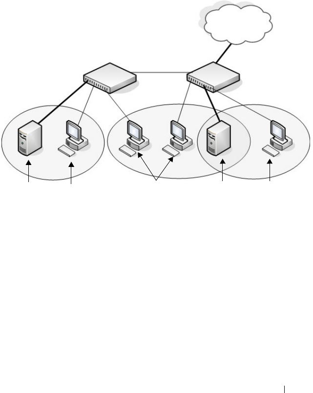
Configuring VLANs 699
Figure 21-26 shows the network topology for this example. As the figure
shows, there are two switches, two file servers, and many hosts. One switch
has an uplink port that connects it to a layer 3 device and the rest of the
corporate network.
Figure 21-26. Network Topology for Port-Based VLAN Configuration
The network in Figure 21-26 has the following characteristics:
• Each connection to a host represents multiple ports and hosts.
• The Payroll and File servers are connected to the switches through a LAG.
• Some of the Marketing hosts connect to Switch 1, and some connect to
Switch 2.
• The Engineering and Marketing departments share the same file server.
• Because security is a concern for the Payroll VLAN, the ports and LAG that
are members of this VLAN will accept and transmit only traffic tagged
with VLAN 400.
• The Sales staff might connect to a port on Switch 1 or Switch 2.
VLAN 400
Payroll
Payroll
Server
Shared File
Server
Payroll
Hosts
Marketing
Hosts
Engineering
Hosts
Switch 1 Switch 2
VLAN 100
Engineering
VLAN 200
Marketing
LAN/WAN

700 Configuring VLANs
Table 21-10 shows the port assignments on the switches.
Table 21-10. Switch Port Connections
Port/LAG Function
Switch 1
1 Connects to Switch 2
2–15 Host ports for Payroll
16–20 Host ports for Marketing
LAG1 (ports 21–24) Connects to Payroll server
Switch 2
1 Connects to Switch 1
2–10 Host ports for Marketing
11–30 Host ports for Engineering
LAG1 (ports 35–39) Connects to file server
LAG2 (ports 40–44) Uplink to router.
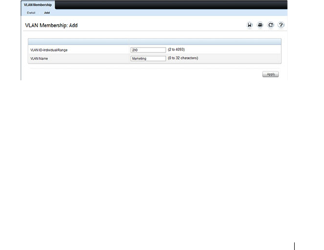
Configuring VLANs 701
Configuring VLANs Using Dell OpenManage Administrator
This example shows how to perform the configuration by using the web-
based interface.
Configure the VLANs and Ports on Switch 1
Use the following steps to configure the VLANs and ports on Switch 1. None
of the hosts that connect to Switch 1 use the Engineering VLAN (VLAN
100), so it is not necessary to create it on that switch.
To configure Switch 1:
1
Create the Marketing, Sales, and Payroll VLANs.
a
From the
Switching
→
VLAN
→
VLAN Membership page, click
Add.
b
In the
VLAN ID
field, enter 200.
c
In the
VLAN Name
field, enter Marketing.
d
Click
Apply
.
Figure 21-27. Add VLANs
e
Repeat steps b–d to create VLANs 300 (Sales) and 400 (Payroll).
2
Assign ports 16–20 to the Marketing VLAN.
a
From the
Switching
→
VLAN
→
VLAN Membership page, select
200-Marketing from the Show VLAN field.
b
In the
Static
row, click the space for ports 13–16 so the U (untagged)
displays for each port.
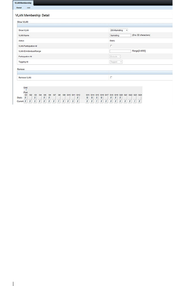
702 Configuring VLANs
Figure 21-28. VLAN Membership - VLAN 200
3
Click
Apply
.
4
Assign ports 2–15 and LAG1 to the Payroll VLAN.
a
From the
Switching
→
VLAN
→
VLAN Membership page, select
400-Payroll from the Show VLAN field.
b
In the Static row, click the space for ports 2–15 and LAG 1 so the U
(untagged) displays for each port, and then click
Apply
.
5.
Configure LAG 1 to be in general mode and specify that the LAG will
accept tagged or untagged frames, but that untagged frames will be
transmitted tagged with PVID 400.
a.
From the
Switching
→
VLAN
→
LAG Settings page, make sure Po1
is selected.
b.
Configure the following settings:
• Port VLAN Mode — General
•PVID — 400
• Frame Type — AdmitAll
c.
Click
Apply
.
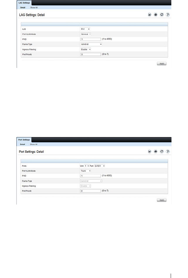
Configuring VLANs 703
Figure 21-29. LAG Settings
6
Configure port 1 as a trunk port.
a
From the
Switching
→
VLAN
→
Port Settings page, make sure port
Gi1/0/1 i
s selected.
b
From the
Port VLAN Mode
field, select Trunk.
c
Click
Apply
.
Figure 21-30. Trunk Port Configuration
7
From the
Switching
→
VLAN
→
VLAN Membership page, verify that
port 1 is marked as a tagged member (T) for each VLAN.
Figure 21-31 shows VLAN 200, in which port 1 is a tagged member, and
ports 13–16 are untagged members.
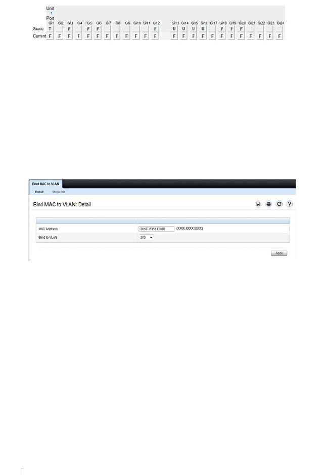
704 Configuring VLANs
Figure 21-31. Trunk Port Configuration
8
Configure the MAC-based VLAN information.
a
Go to the
Switching
→
VLAN
→
Bind MAC to VLAN page.
b
In the
MAC Address
field, enter a valid MAC address, for example
00:1C:23:55:E9:8B.
c
In the
Bind to VLAN
field, enter 300, which is the Sales VLAN ID.
d
Click
Apply
.
Figure 21-32. Trunk Port Configuration
e
Repeat steps b–d to add additional MAC address-to-VLAN
information for the Sales department.
9
To save the configuration so that it persists across a system reset, use the
following steps:
a
Go to the
System
→
File Management
→
Copy Files page
b
Select Copy Configuration and ensure that Running Config is the
source and Startup Config is the destination.
c
Click
Apply
.

Configuring VLANs 705
Configure the VLANs and Ports on Switch 2
Use the following steps to configure the VLANs and ports on Switch 2. Many
of the procedures in this section are the same as procedures used to configure
Switch 1. For more information about specific procedures, see the details and
figures in the previous section.
To configure Switch 2:
1.
Create the Engineering, Marketing, Sales, and Payroll VLANs.
Although the Payroll hosts do not connect to this switch, traffic from the
Payroll department must use Switch 2 to reach the rest of the network and
Internet through the uplink port. For that reason, Switch 2 must be aware
of VLAN 400 so that traffic is not rejected by the trunk port.
2.
Configure LAG 1 as a general port so that it can be a member of multiple
VLANs.
a.
From the
Switching
→
VLAN
→
LAG Settings page, make sure Po1
is selected.
b.
From the
Port VLAN Mode
field, select General.
c.
Click
Apply
.
3.
Configure port 1 as a trunk port.
4.
Configure LAG2 as a trunk port.
5.
Assign ports 1–10 to VLAN 200 as untagged (U) members.
6.
Assign ports 11–30 to VLAN 100 as untagged (U) members.
7.
Assign LAG1 to VLAN 100 and 200 as a tagged (T) member.
8.
Assign port 1 and LAG2 to VLAN 100, VLAN 200, VLAN 300, and VLAN
400 as a tagged (T) member.
9.
Configure the MAC-based VLAN information.
10.
If desired, copy the running configuration to the startup configuration.

706 Configuring VLANs
Configuring VLANs Using the CLI
This example shows how to perform the same configuration by using CLI
commands.
Configure the VLANs and Ports on Switch 1
Use the following steps to configure the VLANs and ports on Switch 1. None
of the hosts that connect to Switch 1 use the Engineering VLAN (VLAN
100), so it is not necessary to create it on that switch.
To configure Switch 1:
1.
Create VLANs 200 (Marketing), 300 (Sales), and 400 (Payroll), and
associate the VLAN ID with the appropriate name.
console#configure
console(config)#vlan 200,300,400
console(config)#vlan 200
console(config-vlan200)#name Marketing
console(config-vlan200)#exit
console(config)#vlan 300
console(config-vlan300)#name Sales
console(config-vlan300)#exit
console(config)#vlan 400
console(config-vlan400)#name Payroll
console(config-vlan400)#exit
2.
Assign ports 16–20 to the Marketing VLAN.
console(config)#interface range tengigabitEthernet
1/0/16-20
console(config-if)#switchport mode access
console(config-if)#switchport access vlan 200
console(config-if)#exit
3.
Assign ports 2–15 to the Payroll VLAN
console(config)#interface range tengigabitEthernet
1/0/2-15
console(config-if)#switchport mode access
console(config-if)#switchport access vlan 400
console(config-if)#exit

Configuring VLANs 707
4.
Assign LAG1 to the Payroll VLAN and specify that frames will always be
transmitted tagged with a VLAN ID of 400. By default, all VLANs are
members of a trunk port.
console(config)#interface port-channel 1
console(config-if-Po1)#switchport mode trunk
console(config-if-Po1)#switchport trunk native
vlan 400
console(config-if-Po1)#exit
5.
Configure port 1 as a trunk port and add VLAN 200, VLAN 300, and
VLAN 400 as members. All VLANs are added to trunk ports by default,
including those created after the trunk port has been created.
console(config)#interface tengigabitEthernet 1/0/1
console(config-if-Te1/0/1)#switchport mode trunk
console(config-if-Te1/0/1)#exit
6.
Configure the MAC-based VLAN information.
The following commands show how to associate a system with a MAC
address of 00:1C:23:55:E9:8B with VLAN 300. Repeat the
vlan association
mac
command to associate additional MAC addresses with VLAN 300.
console(config)#vlan 10
console(config-vlan10)#vlan association mac
00:1C:23:55:E9:8B 300
console(config-vlan10)#exit
console(config)#exit
7.
To save the configuration so that it persists across a system reset, use the
following command:
console#copy running-config startup-config

708 Configuring VLANs
8.
View the VLAN settings.
console#show vlan
9.
View the VLAN membership information for a port.
console#show interfaces switchport te1/0/1
Port: Te1/0/1
VLAN Membership mode:Trunk Mode
Operating parameters:
PVID: 1
Ingress Filtering: Enabled
Acceptable Frame Type: VLAN Only
Default Priority: 0
GVRP status:Disabled
Protected:Disabled
Port Te1/0/1 is member in:
VLAN Name Egress rule Type
---- ----------------- ----------- --------
200 Marketing Tagged Static
300 Sales Tagged Static
400 Payroll Tagged Static
VLAN Name Ports Type Authorization
----- --------- ------------ --------- -------------
1 Default Po1-1248,
Te1/0/2-15,
Te1/0/21-24
Te1/1/1-2
Default Required
200 Marketing Te1/0/1,
Te1/0/16-20
Static Required
300 Sales Te1/0/1 Static Required
400 Payroll Te1/0/1-15 Static Required

Configuring VLANs 709
Configure the VLANs and Ports on Switch 2
Use the following steps to configure the VLANs and ports on Switch 2. Many
of the procedures in this section are the same as procedures used to configure
Switch 1. For more information about specific procedures, see the details and
figures in the previous section.
To configure Switch 2:
1.
Create the Engineering, Marketing, Sales, and Payroll VLANs.
Although the Payroll hosts do not connect to this switch, traffic from the
Payroll department must use Switch 2 to reach the rest of the network and
Internet through the uplink port. For that reason, Switch 2 must be aware
of VLAN 400 so that traffic is not rejected by the trunk port.
2.
Configure ports 2-10 as access ports and add VLAN 200 to the ports.
3.
Configure ports 11–30 as access ports and add VLAN 100 to the ports.
4.
Configure LAG 1 as a general port so that it can be a member of multiple
untagged VLANs and add VLAN 100 and VLAN 200 to the LAG.
5.
Configure port 1 and LAG 2 trunk ports and add VLAN 100, VLAN 200,
VLAN 300, and VLAN 400 to the port and LAG.
6.
Configure the MAC-based VLAN information.
7.
If desired, copy the running configuration to the startup configuration.
8
View VLAN information for the switch and ports.

710 Configuring VLANs
Configuring a Voice VLAN
The commands in this example create a VLAN for voice traffic with a VLAN
ID of 25. Port 10 is set to an 802.1Q VLAN. In in this example, there are
multiple devices connected to port 10, so the port must be in general mode in
order to enable MAC-based 802.1X authentication. Next, Voice VLAN is
enabled on the port with the Voice VLAN ID set to 25. Finally, Voice VLAN
authentication is disabled on port 10 because the phone connected to that
port does not support 802.1X authentication. All other devices are required to
use 802.1X authentication for network access. For more information about
802.1X authentication, see "Configuring Port and System Security" on
page 503.
To configure the switch:
1
Create the voice VLAN.
console#configure
console(config)#vlan 25
console(config-vlan25)#exit
2
Enable the Voice VLAN feature on the switch.
console(config)#voice vlan
3
Configure port 10 to be in general mode.
console(config)#interface gi1/0/10
console(config-if-Gi1/0/10)#switchport mode
general
4
Enable port-based 802.1X authentication on the port. This step is required
only if there are multiple devices that use port-based authentication
connected to the port.
console(config-if-Gi1/0/10)#dot1x port-control
mac-based
5
Enable the voice VLAN feature on the interface
console(config-if-Gi1/0/10)#voice vlan 25
NOTE: In an environment where the IP phone uses LLDP-MED to obtain
configuration information, an additional step to enable LLDP-MED on the
interface would be required by issuing the lldp med command in Interface
Configuration mode.

Configuring VLANs 711
6
Disable authentication for the voice VLAN on the port. This step is
required only if the voice phone does not support port-based
authentication.
console(config-if-Gi1/0/10)#voice vlan auth
disable
7
Exit to Privileged Exec mode.
console(config-if-Gi1/0/10)#<CTRL+Z>
8
View the voice VLAN settings for port 10.
console#show voice vlan interface gi1/0/10
Interface............................. Gi1/0/10
Voice VLAN Interface Mode............. Enabled
Voice VLAN ID......................... 25
Voice VLAN COS Override............... False
Voice VLAN DSCP Value................. 46
Voice VLAN Port Status................ Disabled
Voice VLAN Authentication............. Disabled
Configuring a Private VLAN
1
Configure the VLANs and their roles:
This example configures VLAN 100 as the primary VLAN, secondary
VLAN 101 as the community VLAN and secondary VLANs 102 and 103 as
the isolated VLANs:
switch# configure
switch(config)# vlan 100
switch(config-vlan-100)# private-vlan primary
switch(config-vlan-100)# exit
switch(config)# vlan 101
switch(config-vlan-101)# private-vlan community
switch(config-vlan-101)# exit
switch(config)# vlan 102
switch(config-vlan-102)# private-vlan isolated
switch(config-vlan-102)# exit
switch(config)# vlan 103
switch(config-vlan-103)# private-vlan isolated
switch(config-vlan-103)# exit
2
Associate the community and isolated VLANs with the primary VLAN.
switch(config)# vlan 100

712 Configuring VLANs
switch(config-vlan-100)# private-vlan association 101-102
switch(config-vlan-100)# exit
This completes the configuration of the private VLAN. The only
remaining step is to assign the ports to the private VLAN.
3
Assign the router connected port to the primary VLAN:
console(config)#interface te1/1/1
console(config-if-Te1/1/1)#switchport mode private-vlan
promiscuous
console(config-if-Te1/1/1)#switchport private-vlan mapping 100
101-102
console(config-if-Te1/1/1)#exit
4
Assign the community VLAN ports:
console(config)#interface gi1/0/11
console(config-if-Gi1/0/11)#switchport mode private-vlan host
console(config-if-Gi1/0/11)#switchport private-vlan host-
association 100 101
console(config-if-Gi1/0/11)#interface gi1/0/12
console(config-if-Gi1/0/12)#switchport mode private-vlan host
console(config-if-Gi1/0/12)#switchport private-vlan host-
association 100 101
5
Assign the isolated VLAN ports:
console(config)#interface gi1/0/10
console(config-if-Gi1/0/10)#switchport mode private-vlan host
console(config-if-Gi1/0/10)#switchport private-vlan host-
association 100 102
console(config-if-Gi1/0/10)#interface gi2/0/10
console(config-if-Gi2/0/10)#switchport mode private-vlan host
console(config-if-Gi2/0/10)#switchport private-vlan host-
association 100 102
console(config-if-Gi2/0/10)#interface gi2/0/11
console(config-if-Gi2/0/11)#switchport mode private-vlan host
console(config-if-Gi2/0/11)#switchport private-vlan host-
association 100 102
6
Show the configuration:
console(config)#show vlan private-vlan type
VLAN Type
---- -----------------------
100 primary
101 community
102 isolated

Configuring VLANs 713
103 isolated
console#show vlan private-vlan
Primary VLAN Secondary VLAN Community
------------ -------------- -------------------
100 102 101
console(config)#show vlan
VLAN Name Ports Type
----- ----------- ------------- -------------
1 default Po1-128, Default
Te1/1/1,
Gi1/0/1-10,
Gi1/0/13-24
100 VLAN0100 Te1/1/1, Static
Gi1/0/11-12
101 VLAN0101 Gi1/0/11 Static
102 VLAN0102 Gi1/0/12 Static

714 Configuring VLANs

Configuring the Spanning Tree Protocol 715
22
Configuring the Spanning Tree
Protocol
This chapter describes how to configure the Spanning Tree Protocol (STP)
settings on the switch.
The topics covered in this chapter include:
• STP Overview
•RSTP-PV
• Default STP Values
• Configuring Spanning Tree (Web)
• Configuring Spanning Tree (CLI)
• STP Configuration Examples
STP Overview
STP is a layer 2 protocol that provides a tree topology for switches on a
bridged LAN. STP allows a network to have redundant paths without the risk
of network loops. STP uses the spanning tree algorithm to provide a single
path between end stations on a network.
Dell Networking series switches support Classic STP, Multiple STP, and Rapid
STP.
What Are Classic STP, Multiple STP, and Rapid STP?
Classic STP provides a single path between end stations, avoiding and
eliminating loops.
Multiple Spanning Tree Protocol (MSTP) supports multiple instances of
Spanning Tree to efficiently channel VLAN traffic over different interfaces.
Each instance of the Spanning Tree behaves in the manner specified in IEEE
802.1w, Rapid Spanning Tree (RSTP), with slight modifications in the
working but not the end effect (chief among the effects, is the rapid

716 Configuring the Spanning Tree Protocol
transitioning of the port to Forwarding). The difference between the RSTP
and the traditional STP (IEEE 802.1d) is the ability to configure and
recognize full-duplex connectivity and ports which are connected to end
stations, resulting in rapid transitioning of the port to the Forwarding state
and the suppression of Topology Change Notifications.
MSTP is compatible with both RSTP and STP. It behaves appropriately when
connected to STP and RSTP bridges. A MSTP bridge can be configured to
behave entirely as a RSTP bridge or a STP bridge.
How Does STP Work?
The switches (bridges) that participate in the spanning tree elect a switch to
be the root bridge for the spanning tree. The root bridge is the switch with the
lowest bridge ID, which is computed from the unique identifier of the bridge
and its configurable priority number. When two switches have an equal
bridge ID value, the switch with the lowest MAC address is the root bridge.
After the root bridge is elected, each switch finds the lowest-cost path to the
root bridge. The port that connects the switch to the lowest-cost path is the
root port on the switch. The switches in the spanning tree also determine
which ports have the lowest-path cost for each segment. These ports are the
designated ports. Only the root ports and designated ports are placed in a
forwarding state to send and receive traffic. All other ports are put into a
blocked state to prevent redundant paths that might cause loops. Both
internal and external path costs can be configured. For STP, RSTP, and the
MSTP CIST, only the external path costs are utilized in the lowest path cost
calculation. The internal path cost is used by the MST instances.
To determine the root path costs and maintain topology information,
switches that participate in the spanning tree use Bridge Protocol Data Units
(BPDUs) to exchange information.
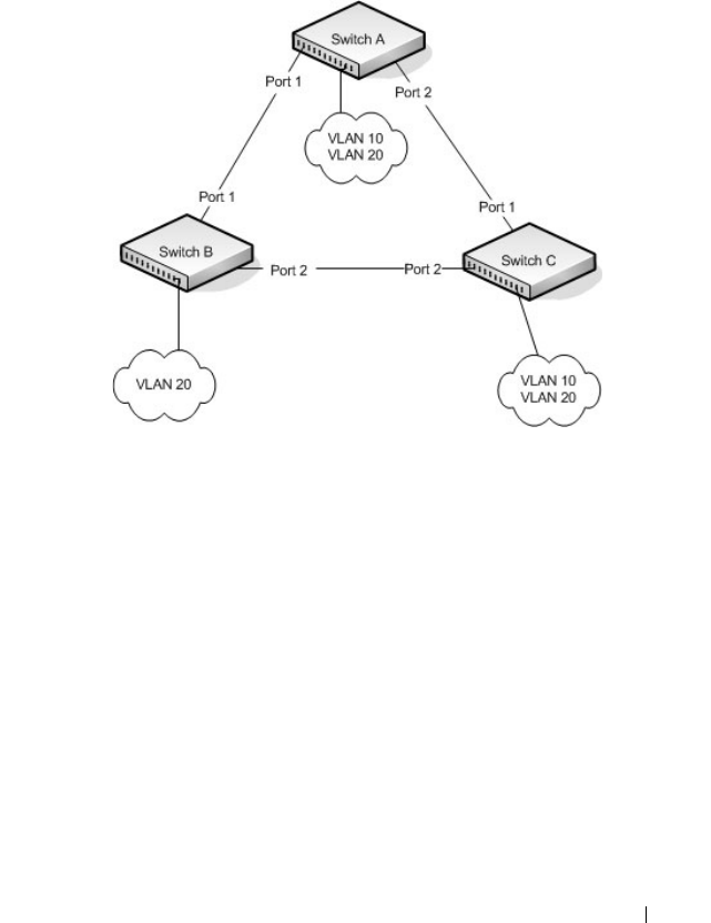
Configuring the Spanning Tree Protocol 717
How Does MSTP Operate in the Network?
In the following diagram of a small 802.1d bridged network, STP is necessary
to create an environment with full connectivity and without loops.
Figure 22-1. Small Bridged Network
Assume that Switch A is elected to be the Root Bridge, and Port 1 on Switch
B and Switch C are calculated to be the root ports for those bridges, Port 2 on
Switch B and Switch C would be placed into the Blocking state. This creates a
loop-free topology. End stations in VLAN 10 can talk to other devices in
VLAN 10, and end stations in VLAN 20 have a single path to communicate
with other VLAN 20 devices.

718 Configuring the Spanning Tree Protocol
Figure 22-2 shows the logical single STP network topology.
Figure 22-2. Single STP Topology
For VLAN 10 this single STP topology is fine and presents no limitations or
inefficiencies. On the other hand, VLAN 20's traffic pattern is inefficient. All
frames from Switch B will have to traverse a path through Switch A before
arriving at Switch C. If the Port 2 on Switch B and Switch C could be used,
these inefficiencies could be eliminated. MSTP does just that, by allowing the
configuration of MSTIs based upon a VLAN or groups of VLANs. In this
simple case, VLAN 10 could be associated with Multiple Spanning Tree
Instance (MSTI)1 with an active topology similar to Figure 22-2 and VLAN
20 could be associated with MSTI 2 where Port 1 on both Switch A and
Switch B begin discarding and all others forwarding. This simple modification
creates an active topology with a better distribution of network traffic and an
increase in available bandwidth.


720 Configuring the Spanning Tree Protocol
In order for MSTP to correctly establish the different MSTIs as above, some
additional changes are required. For example, the configuration would have
to be the same on each and every bridge. That means that Switch B would
have to add VLAN 10 to its list of supported VLANs (shown in Figure 22-3
with a *). This is necessary with MSTP to allow the formation of Regions
made up of all switches that exchange the same MST Configuration
Identifier. It is within only these MST Regions that multiple instances can
exist. It will also allow the election of Regional Root Bridges for each instance.
One common and internal spanning tree (CIST) Regional Root for the CIST
and an MSTI Regional Root Bridge per instance will enable the possibility of
alternate paths through each Region. Above Switch A is elected as both the
MSTI 1 Regional Root and the CIST Regional Root Bridge, and after
adjusting the Bridge Priority on Switch C in MSTI 2, it would be elected as
the MSTI 2 Regional Root.
To further illustrate the full connectivity in an MSTP active topology, the
following rules apply:
1
Each Bridge or LAN is in only one Region.
2
Every frame is associated with only one VID.
3
Frames are allocated either to the IST or MSTI within any given Region.
4
The internal spanning tree (IST) and each MSTI provides full and simple
connectivity between all LANs and Bridges in a Region.
5
All Bridges within a Region reach a consistent agreement as to which ports
interconnect that Region to a different Region and label those as Boundary
Ports.
6
At the Boundary Ports, frames allocated to the CIST or MSTIs are
forwarded or not forwarded alike.
7
The CIST provides full and simple connectivity between all LANs and
Bridges in the network.
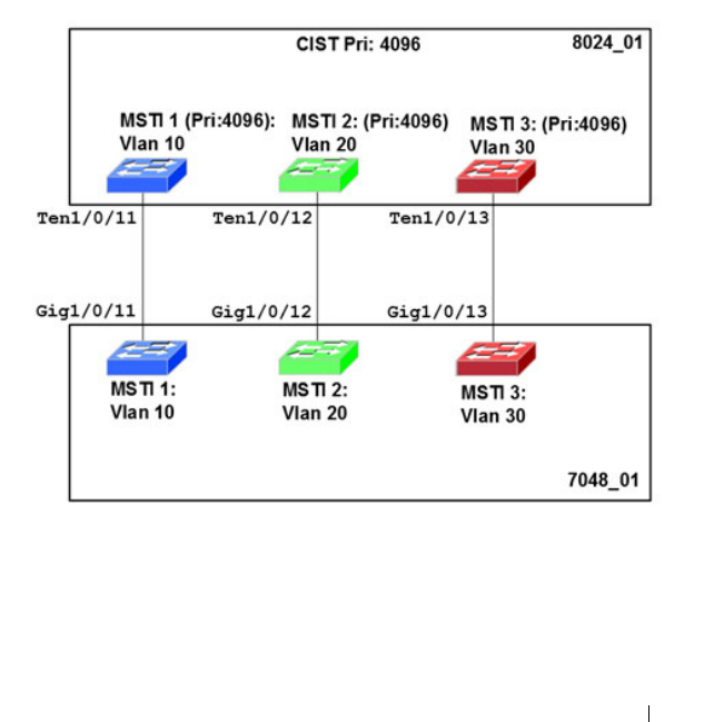
Configuring the Spanning Tree Protocol 721
MSTP with Multiple Forwarding Paths
Consider the physical topology shown in Figure 22-4. It might be assumed
that MSTI 2 and MSTI 3 would follow the most direct path for VLANs 20
and 30. However, using the default path costs, this is not the case. MSTI
operates without considering the VLAN membership of the ports. This results
in unexpected behavior if the active topology of an MSTI depends on a port
that is not a member of the VLAN assigned to the MSTI and the port is
selected as root port. In this configuration, port TE 1/0/11 is selected as the
root port and ports TE1/0/12 and TE1/0/13 are blocked. To resolve the issue,
set the port path cost of the directly connected links to allow the MSTIs to
connect directly.
Figure 22-4. MSTP with Multiple Forwarding Paths

722 Configuring the Spanning Tree Protocol
What are the Optional STP Features?
The Dell Networking series switches support the following optional STP
features:
• BPDU flooding
•PortFast
• BPDU filtering
• Root guard
• Loop guard
• BPDU protection
BPDU Flooding
The BPDU flooding feature determines the behavior of the switch when it
receives a BPDU on a port that is disabled for spanning tree. If BPDU
flooding is configured, the switch will flood the received BPDU to all the
ports on the switch which are similarly disabled for spanning tree.
Port Fast
The PortFast feature reduces the STP convergence time by allowing edge
ports that are connected to end devices (such as a desktop computer, printer,
or file server) to transition to the forwarding state without going through the
listening and learning states.
BPDU Filtering
Ports that have the PortFast feature enabled continue to transmit BPDUs.
The BPDU filtering feature prevents PortFast-enabled ports from sending
BPDUs.
If BPDU filtering is configured globally on the switch, the feature is
automatically enabled on all operational PortFast-enabled ports. These ports
are typically connected to hosts that drop BPDUs. However, if an operational
edge port receives a BPDU, the BPDU filtering feature disables PortFast and
allows the port to participate in the spanning tree calculation.
Enabling BPDU filtering on a specific port prevents the port from sending
BPDUs and allows the port to drop any BPDUs it receives.

Configuring the Spanning Tree Protocol 723
Root Guard
Root guard is another way of controlling the spanning-tree topology other
than setting the bridge priority or path costs. Root guard ensures that a port
does not become a root port or a blocked port. When a switch is elected as
the root bridge, all ports are assigned roles as designated ports unless two or
more ports of the root bridge are connected in a loop. If the switch receives a
superior STP BPDU on a root-guard enabled port, the root guard feature
moves the port to a root-inconsistent spanning-tree state. No traffic is
forwarded across the port, but it continues to receive BPDUs, discards
received traffic, and is included in the active topology. Essentially, this is
equivalent to the IEEE 802.1D listening state. By not transitioning the port
on which the superior BPDU has been received to the forwarding state
(designated role), root guard helps maintain the existing spanning-tree
topology.
When the STP mode is configured as MSTP, the port may be a designated
port in one MSTI and an alternate port in the CIST, etc. Root guard is a per
port (not a per port instance command) configuration, so all the MSTP
instances this port participates in should not be expected to take on a root
role.
Loop Guard
Loop guard protects a network from forwarding loops induced by BPDU
packet loss. The reasons for failing to receive packets are numerous, including
heavy traffic, software problems, incorrect configuration, and unidirectional
link failure. When a non-designated port no longer receives BPDUs, the
spanning tree algorithm considers the link to be loop free and transitions the
link from blocking to forwarding. Once in the forwarding state, the link may
create a loop in the network.
Enabling loop guard prevents such accidental loops. When a port is no longer
receiving BPDUs and the max age timer expires, the port is moved to a
loop-
inconsistent blocking state
. In the loop-inconsistent blocking state, traffic is
not forwarded so the port behaves as if it is in the blocking state; that is, it
discards received traffic, does not learn MAC addresses, and is not part of the
active topology. The port will remain in this state until it receives a BPDU. It
will then transition through the normal spanning tree states based on the
information in the received BPDU.

724 Configuring the Spanning Tree Protocol
BPDU Protection
When the switch is used as an access layer device, most ports function as edge
ports that connect to a device such as a desktop computer or file server. The
port has a single, direct connection and is configured as an edge port to
implement the fast transition to a forwarding state. When the port receives a
BPDU packet, the system sets it to non-edge port and recalculates the
spanning tree, which causes network topology flapping. In normal cases, these
ports do not receive any BPDU packets. However, someone may forge BPDU
to maliciously attack the switch and cause network flapping.
BPDU protection can be enabled in RSTP to prevent such attacks. When
BPDU protection is enabled, the switch disables an edge port that has
received BPDU and notifies the network manager about it.
RSTP-PV
Dell Networking switches support both Rapid Spanning Tree Per VLAN
(RSTP-PV) and Spanning Tree Per VLAN (STP-PV) with a high degree of
interoperability with other vendor implementations, such as Cisco's PVST+
and RPVST+. RSTP-PV is the IEEE 802.1w (RSTP) standard implemented
per VLAN. A single instance of rapid spanning tree (RSTP) runs on each
configured VLAN. Each RSTP instance on a VLAN has a root switch. The
RSTP-PV protocol state machine, port roles, port states, and timers are
similar to those defined for RSTP. RSTP-PV embeds the DRC and
IndirectLink Fast Rapid Convergence (IRC) features, which cannot be
disabled.
STP-PV is the IEEE 802.1s (STP) standard implemented per VLAN. The
STP-PV-related state machine, roles, and timers are similar to those defined
for STP. STP-PV does not have the DirectLink Rapid Convergence (DRC) or
IndirectLink Rapid Convergence (IRC) features enabled by default. These
features can be enabled by the switch administrator.
NOTE: Loop Guard should be configured only on non-designated ports. These
include ports in alternate or backup roles. Root ports and designated ports
should not have loop guard enabled so that they can forward traffic.

Configuring the Spanning Tree Protocol 725
The switch spanning tree configuration is global in nature. Enabling RSTP-
PV disables other spanning tree modes on the switch. The switch cannot
operate with some ports configured to operate in standard spanning tree
mode and others to operate in RSTP-PV mode. However, RSTP-PV has
fallback modes for compatibility with standards-based versions of spanning
tree.
Access Ports—For an access port, normal IEEE BPDUs will be received and
sent, though STP-PV or RSTP-PV is enabled on the switch. BPDUs received
on the access port will be associated with the CST instance.
Trunk Ports—If the native VLAN on an IEEE 802.1Q trunk is VLAN 1:
• VLAN 1 STP BPDUs are sent to the IEEE STP MAC address
(0180.c200.0000), untagged.
• VLAN 1 STP BPDUs are also sent to the SSTP MAC address, untagged.
• Non-VLAN 1 STP BPDUs are sent to the SSTP MAC address (also called
the Shared Spanning Tree Protocol [SSTP] MAC address, 0100.0ccc.cccd),
tagged with a corresponding IEEE 802.1Q VLAN tag.
If the native VLAN on an IEEE 802.1Q trunk is not VLAN 1:
• VLAN 1 STP BPDUs are sent to the SSTP MAC address, tagged with a
corresponding IEEE 802.1Q VLAN tag.
• VLAN 1 STP BPDUs are also sent to the IEEE STP MAC address on the
Native VLAN of the IEEE 802.1Q trunk, untagged.
• Non-VLAN 1 STP BPDUs are sent to the SSTP MAC address, tagged with
a corresponding IEEE 802.1Q VLAN tag.
DirectLink Rapid Convergence
The DirectLink Rapid Convergence (DRC) feature is designed for an access-
layer switch that has redundant blocked uplinks. It operates on ports blocked
by spanning tree. DRC can be configured for the entire switch; it cannot be
enabled for individual VLANs.
The DRC feature is based on the concept of an uplink group. An uplink group
consists of all the ports that provide a path to the root bridge (the root port
and any blocked ports). If the root port fails, the blocked port with next
lowest cost from the uplink group is selected and immediately put in the
forwarding state without going through the standard spanning tree listening
and learning states.

726 Configuring the Spanning Tree Protocol
To accelerate convergence time once DRC has switched over to a new root
port, STP-PV transmits dummy packets out the new root port, with the
source MAC addresses taken from its forwarding table. The destination
address is an SSTP MAC address that ensures that the packet is flooded on
the whole network. The packets update the forwarding tables on the other
upstream switches. The rate at which the dummy multicasts are sent can be
configured by the administrator. RSTP-PV has a different mechanism
adopted from IEEE 802.1w that handles the update of the forwarding
database and the fast transition to a new uplink. DRC can be enabled on
RSTP-PV enabled switches but has no effect.
DRC is disabled when the administrator modifies the spanning-tree priority
of a VLAN and is re-enabled only when the default priority is restored.
DRC and Link Up Events
In the event of failure of the primary uplink, a replacement uplink is
immediately selected from the uplink group and put into the forwarding
state. If another port is enabled that, in accordance with STP rules, should
become the primary uplink (root port), the switch delays migrating to the
new port for twice the forwarding delay. The purpose of this delay is two-fold:
• Stability—If the primary uplink is flapping, reenabling the link
immediately can introduce additional instability into the network.
• Reduced Traffic Loss—DRC moves a port into the forwarding state as
soon as it is up, but the connected port obeys the usual STP rules; i.e. it
goes through the listening and learning stages, which take 15 seconds each
by default. Delaying the switchover allows the connected port to go to
through the listening and learning states while the switch is still
transmitting packets on the original uplink.
The optimal behavior is to keep the current uplink active and hold the new
port in the blocked state for twice the forwarding delay.

Configuring the Spanning Tree Protocol 727
IndirectLink Rapid Convergence Feature
To handle indirect link failure, the STP standard requires that a switch
passively wait for “max_age” seconds once a topology change has been
detected. IndirectLink Rapid Convergence (IRC) handles these failures in
two phases:
• Rapid detection of an indirect link failure. Tracking the inferior BPDUs
that a designated bridge detects when it transmits a direct link failure
indicates that a failure has occurred elsewhere in the network.
• Performing an immediate check if the BPDU information stored on a port
is still valid. This is implemented with a new protocol data unit (PDU) and
the Root Link Query message (RLQ).
Receiving an inferior BPDU on a port from the designated bridge indicates
that one of the following has occurred on the designated bridge:
• The path to the root has been lost and the switch starts to advertise a root
with a numerically higher bridge ID (worse root) than the local switch.
• The path cost to the root has increased above the path cost of the local
switch.
IEEE 802.1s behavior is to ignore inferior BPDUs. IRC retains the inferior
BPDUs sent by the designated bridge and processes them to determine if a
failure has occurred on the path to the root. In this case, it must age-out at
least one port. This process occurs only in the case that a bridge in the
network detects a direct link failure.
The switch tracks inferior BPDUs sent by the designated bridge only, since
this is the BPDU that is stored for the port. If, for instance, a newly inserted
bridge starts to send inferior BPDUs, it does not start the IRC feature.
Similar to DRC, the IEEE 802.1w standard incorporated the IRDC feature.
RSTP-PV enabled switches allow IRC to be enabled or disabled, but ignore
the setting as the RSTP-PV state machines already implement IRC.
Reacting to Indirect Link Failures
When an inferior BPDU is received on a non-designated port, phase 2 of IRC
processing starts. An RLQ PDU is transmitted on all non-designated ports
except the port where the inferior BPDU was received and self-looped ports.
This action is intended to verify that the switch can still receive from the root
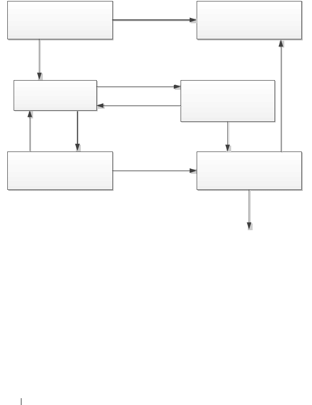
728 Configuring the Spanning Tree Protocol
on ports that should have a path to the root. The port where the switch
received the inferior BPDU is excluded because it already failed; self-looped
and designated ports are eliminated as they do not have a path to the root.
Figure 22-5. IRC Flow
Upon receiving a negative RLQ response on a port, the port has lost
connection to the root and the switch ages-out its BPDU. If all other non-
designated ports received a negative answer, the switch has lost the root and
restarts the STP calculation.
If the response confirms the switch can still access the root bridge via a
particular port, it immediately ages-out the port on which the inferior BPDU
was received.
If the switch only received responses with a root different from the original
root, it has lost the root port and restarts the STP calculation immediately.
Inferior BDPU received. Are there
other non-self-looped
non-designated ports?
Connectivity to root is lost.
Recompute spanning-tree.
No Yes: Can still reach root on a port.
No
Yes -> Send RLQ query on non-designated ports.
Wait for RLQ responses.
Connectivity to root still exists –
age out port with inferior BPDU.
Have received response for every
RLQ sent?
No Are all RLQ responses negative?
No, end
processing
Yes
Negative: Root lost on this port
Age-out the BPDU for this port.
Have received response for
every RLQ sent?
Yes
No
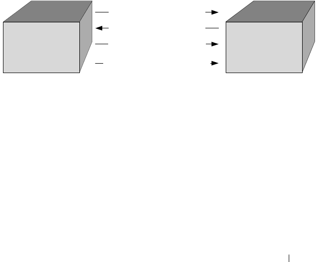
Configuring the Spanning Tree Protocol 729
Interoperability Between STP-PV and RSTP-PV Modes
STP-PV is derived from 802.1D and RSTP-PV is derived from 802.1w. The
fallback mechanism is the same as between a standard 802.1D switch and a
standard 802.1w switch. When a lower protocol version BPDU is received on
a switch that runs a higher protocol version, the latter falls back to the lower
version after its migration delay timer expires.
For example, an RSTP-PV switch, when connected to STP-PV switch, falls
back to the STP-PV protocol after the migration delay timer expires.
Interoperability With IEEE Spanning Tree Protocols
When a switch configured with RSTP-PV receives IEEE standard RSTP
BPDUs on a port, it responds with two versions of BPDUs on the port: SSTP
formatted BPDUs and IEEE standard STP BPDUs. The IEEE standard
BPDUs are processed by the peer switch running MSTP/RSTP, and the SSTP
format BPDUs are flooded across the MSTP/RSTP domain.
Figure 22-6. RSTP-PV and IEEE Spanning Tree Interoperability
Common Spanning Tree
There are differences between the ways that MSTP and RSTP-PV map
spanning tree instances to VLANs: RSTP-PV creates a spanning tree instance
for each VLAN, and MSTP maps one or more VLANs to each MST instance.
Where an RSTP-PV region is connected to an MSTP region, the set of RSTP-
PV instances does not generally match the set of MST instances. Therefore,
the RSTP-PV region and the MSTP region communicate with each other on a
single common spanning tree instance.
For the MSTP region, the MSTP instance communicates to the RSTP-PV
region using the CIST. For the RSTP-PV region, switches use the VLAN 1
RSTP-PV instance as the common spanning tree. On the link between the
RSTP-PV IEEE
IEEE BPDUs for VLAN1 (untagged)
IEEE BPDUs for VLAN1 (untagged)
SSTP BPDUs for VLAN1 (untagged)
SSTP BPDUs for other VLANs (tagged)

730 Configuring the Spanning Tree Protocol
RSTP-PV region and the MSTP region, the RSTP-PV switch sends VLAN1
BPDUs in IEEE standard format, so they can be interpreted by the MSTP
peers. Similarly, the RSTP-PV switch processes incoming MSTP BPDUs as
though they were BPDUs for the VLAN 1 RSTP-PV instance.
If the RSTP-PV switch ports connected to the MSTP switches are configured
with a native VLAN, the RSTP-PV switches are able to detect IEEE standard
format BPDUs arriving from peer switches, incorporate them into the
common spanning tree that operates in the native VLAN (VLAN 1), and
transmit untagged STP or RSTP packets to the STP/RSTP peers, in addition
to the SSTP format BPDUs.
SSTP BPDUs Flooding Across MST (CST) Regions
In addition to the IEEE standard RSTP or STP BPDUs that the RSTP-PV
switch sends to the MSTP (or RSTP or STP) region, the switch sends SSTP
format BPDUs for VLAN 1 untagged. The MSTP switch does not interpret
the SSTP BPDUs as standard BPDUs because they do not use the standard
destination MAC address, so it makes no spanning tree decisions based on
them. Instead, it floods the SSTP BPDUs over all ports in the corresponding
VLAN. These SSTP BPDUs may be multicast over the MSTP region to other
RSTP-PV switches, which use them to maintain the VLAN 1 spanning tree
topology across the MSTP (non-RSTP-PV) switches.
The RSTP-PV switches also send SSTP format BPDUs for the other (non-
VLAN 1) RSTP-PV instances into the MSTP region, tagged with the VID of
their associated VLANs. These SSTP packets are also be multicast by the
switches in the MSTP region, and will reach any other RSTP-PV regions
connected to the MSTP region. The switches in the remote RSTP-PV regions
receive and process them as normal RSTP-PV BPDUs. Thus, RSTP-PV
instances are transparently expanded across the MSTP region and their
spanning trees span the MSTP region. For RSTP-PV, the MSTP region is
treated as a single hub.
Interoperability with RSTP
In Figure 22-7:
• SW1 and SW2 are Dell Networking switches running RSTP-PV with
default bridge priority 32768.
• SW3 is a Dell Networking switch running RSTP with default bridge
priority 32768.
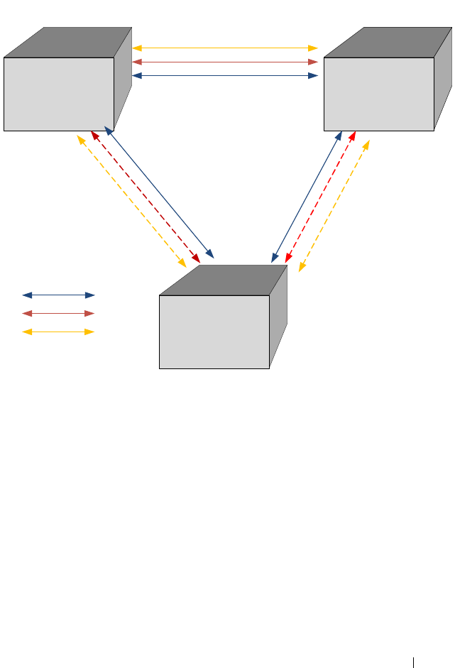
Configuring the Spanning Tree Protocol 731
Figure 22-7. RSTP-PV and RSTP Interoperability
SW3 sends IEEE STP BPDUs to the IEEE multicast MAC address as
untagged frames. These BPDUs are processed by the VLAN 1 STP instance
on the RSTP-PV switch as part of the VLAN 1 STP instance.
The RSTP-PV side sends IEEE STP BPDUs corresponding to the VLAN 1
STP to the IEEE MAC address as untagged frames across the link. At the
same time, SSTP BPDUs are sent as untagged frames. IEEE switches simply
flood the SSTP BPDUs throughout VLAN 1. This facilitates RSTP-PV
connectivity in case there are other RSTP-PV switches connected to the IEEE
STP domain.
For non-native VLANs (VLANs 2–4093), the RSTP-PV switch sends SSTP
BPDUs, tagged with their VLAN number. The VLAN STP instances are
multicast across the RSTP region, as if it were a hub switch.
SW1 SW2
SW3
1/0/1 1/0/1
1/0/2
1/0/3 1/0/4
Root for VLAN1
1/0/1
Root for VLAN2 and 3
VLAN1
VLAN2
VLAN3

732 Configuring the Spanning Tree Protocol
The VLAN 1 STP instance of SW1 and SW2 are joined with the STP
instance running in SW3. VLANs 2 and 3 consider the path across SW3 as
another segment linking SW1 and SW2, and their SSTP information is
multicast across SW3.
The bridge priority of SW1 and SW2 for VLAN1 instance is 32769 (bridge
priority + VLAN identifier).
The bridge priority of SW3 is 32768, per the IEEE 802.w standard.
SW3 is selected as Root Bridge for the VLAN1 instance that is CST, and SW1
is selected as Root Bridge for VLAN2 and VLAN3 (based on the low MAC
address of SW1).
Interoperability with MSTP
RSTP-PV runs an individual RSTP instance for each VLAN. MSTP maps
VLANs to MSTIs, so one-to-one mapping between VLAN and STP instance
is not possible.
MSTP runs multiple MSTIs inside a region and maps them to the CIST on
the border ports. The interoperability model must ensure that internal MSTIs
are aware of changes to any of the RSTP-PV trees. Therefore, the simplest way
to ensure the correct behavior is to join ALL RSTP-PV trees to the CST.
Connecting RSTP-PV trees to the CST ensures that changes in any of the
RSTP-PV STP instances will affect the CST and all MSTIs. This approach
ensures that no changes go unnoticed and no black holes occur in a single
VLAN. As with IEEE STP, every tree in the RSTP-PV domain views the
MSTP regions as virtual bridges with multiple boundary ports. A topology
change in any of RSTP-PV trees will affect the CST and propogate through
every MSTI instance in all MSTP regions. This behavior, consequently, makes
the MSTP topology less stable.
The MSTP implementation simulates RSTP-PV by replicating CIST BPDUs
on the link facing the RSTP-PV domain and sending those BPDUs on ALL
VLANs active on the trunk. The MSTP switch processes IEEE STP VLAN 1
BPDUs received from the RSTP-PV domain using the CIST instance. The
RSTP-PV+ domain interprets the MSTP domain as an RSTP-PV bridge with
all per-VLAN instances claiming the CIST Root as the root of their individual
spanning tree. For the common STP Root elected between MSTP and RSTP-
PV, two options are possible:
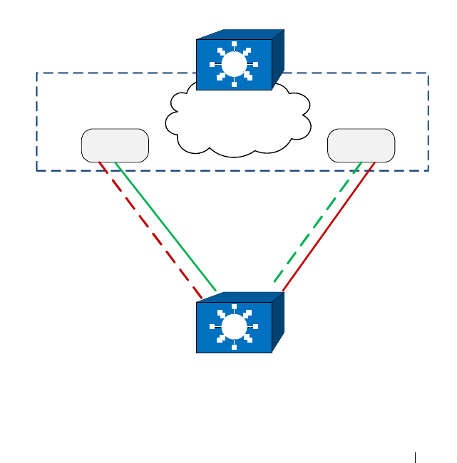
Configuring the Spanning Tree Protocol 733
• The MSTP domain contains the root bridge for ALL VLANs. This implies
that the CIST Root Bridge ID is configured to be better than any RSTP-
PV STP root Bridge ID. If there is only one MSTP region connected to the
RSTP-PV domain, then all boundary ports on the virtual-bridge will be
unblocked and used by RSTP-PV. This is the only supported topology, as
the administrator can manipulate uplink costs on the RSTP-PV side and
obtain optimal traffic engineering results. In Figure 22-8, VLANs 2 and 3
have their STP costs configured to select different uplinks connected to
the MSTP region's boundary ports. Since the CIST Root is inside the
MSTP region, both boundary ports are non-blocking designated and the
load balancing scheme operates as expected.
Figure 22-8. MSTP and RSTP-PV Interoperability
MSTP Region
CIST Root
PVST+ Bridge
Boundary
Port 1
Boundary
Port 2
VLAN 3 STPVLAN 2 STP
×
×

734 Configuring the Spanning Tree Protocol
• The alternative is that the RSTP-PV domain contains the root bridges for
ALL VLANs. This is only true if all RSTP-PV root bridges’ Bridge IDs for
all VLANs are better than the MSTP CIST Root Bridge ID. This is not a
supported topology, because all MSTIs map to CIST on the border link,
and it is not possible to load-balance the MSTIs as they enter the RSTP-
PV domain.
The Dell Networking RSTP-PV implementation does not support the second
option. The MSTP domain must contain the bridge with the best Bridge ID
to ensure that the CIST Root is also the root for all RSTP-PV trees. In any
other case, the MSTP border switch will place the ports that receive superior
BPDUs from the RSTP-PV region in the root-inconsistent state. To resolve
this issue, ensure that the RSTP-PV domain does not have any bridges with
Bridge IDs better than the CIST Root Bridge ID.
Native VLAN Inconsistent State
This occurs if a trunk port receives an untagged SSTP BPDU with a VLAN
type, length, value (TLV) that does not match the VLAN where the BPDU
was received. In this case, the port transitions to the blocked state.
Configuration Examples
See "RSTP-PV Access Switch Configuration Example" on page 756.

Configuring the Spanning Tree Protocol 735
Default STP Values
Spanning tree is globally enabled on the switch and on all ports and LAGs.
Table 22-1 summarizes the default values for STP.
Table 22-1. STP Defaults
Parameter Default Value
Enable state Enabled (globally and on all ports)
Spanning tree mode RSTP (Classic STP, STP-PV, RSTP-PV and
MSTP are disabled)
Switch priority 32768
BPDU flooding Disabled
PortFast mode Disabled
PortFast BPDU filter Disabled
Loop guard Disabled
BPDU protection Disabled
Spanning tree port priority 128
Maximum-aging time 20 seconds
Forward-delay time 15 seconds
Maximum hops 20
Spanning tree transmit hold count 6
MSTP region name MAC address of switch
MSTP included VLANs 1

736 Configuring the Spanning Tree Protocol
Configuring Spanning Tree (Web)
This section provides information about the OpenManage Switch
Administrator pages for configuring and monitoring STP settings on a Dell
Networking N2000, N3000, and N4000 series switches. For details about the
fields on a page, click at the top of the page.
STP Global Settings
The STP Global Settings page contains fields for enabling STP on the
switch.
To display the STP Global Settings page, click Switching
→
Spanning Tree
→
Global Settings in the navigation panel.
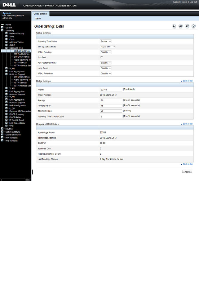
Configuring the Spanning Tree Protocol 737
Figure 22-9. Spanning Tree Global Settings
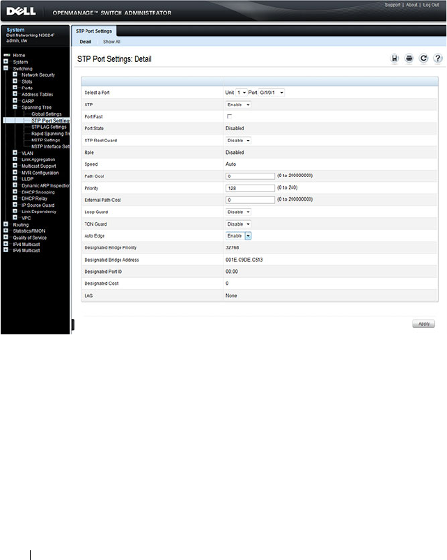
738 Configuring the Spanning Tree Protocol
STP Port Settings
Use the STP Port Settings page to assign STP properties to individual ports.
To display the STP Port Settings page, click Switching
→
Spanning Tree
→
STP Port Settings in the navigation panel.
Figure 22-10. STP Port Settings
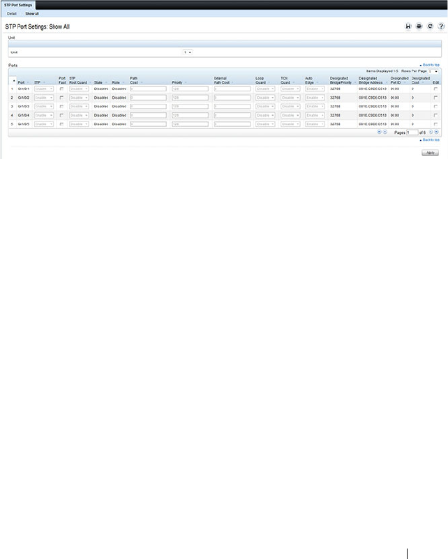
Configuring the Spanning Tree Protocol 739
Configuring STP Settings for Multiple Ports
To configure STP settings for multiple ports:
1
Open the
STP Port Settings
page.
2
Click
Show All
to display the
STP Port Table
.
Figure 22-11. Configure STP Port Settings
3
For each port to configure, select the check box in the
Edit
column in the
row associated with the port.
4
Select the desired settings.
5
Click
Apply
.
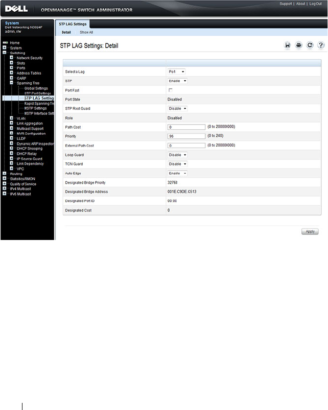
740 Configuring the Spanning Tree Protocol
STP LAG Settings
Use the STP LAG Settings page to assign STP aggregating ports parameters.
To display the STP LAG Settings page, click Switching
→
Spanning Tree
→
STP LAG Settings in the navigation panel.
Figure 22-12. STP LAG Settings
Configuring STP Settings for Multiple LAGs
To configure STP settings on multiple LAGS:
1
Open the
STP LAG Settings
page.
2
Click
Show All
to display the
STP LAG Table
.
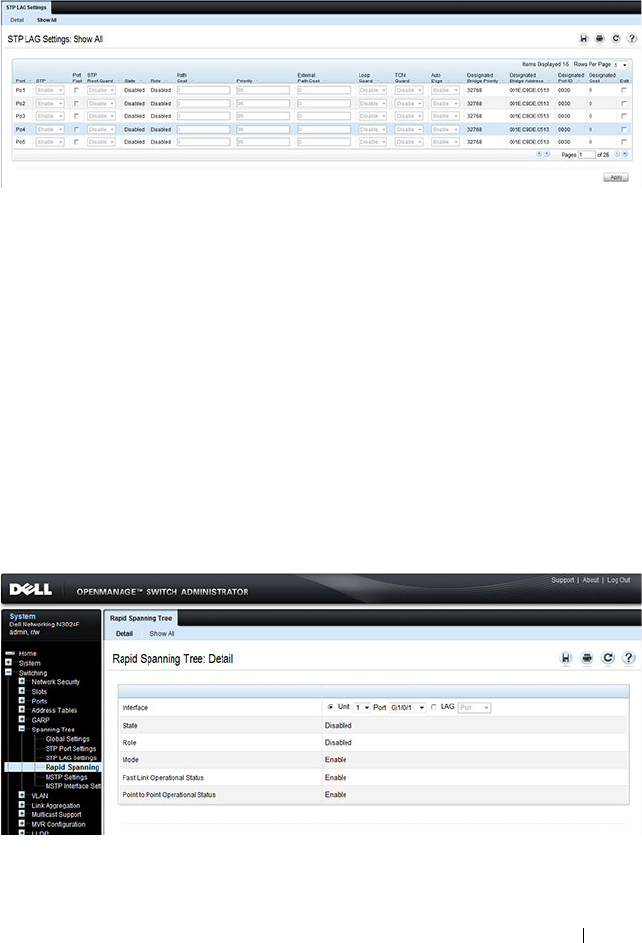
Configuring the Spanning Tree Protocol 741
Figure 22-13. Configure STP LAG Settings
3
For each LAG to configure, select the check box in the
Edit
column in the
row associated with the LAG.
4
Select the desired settings.
5
Click
Apply
.
Rapid Spanning Tree
Rapid Spanning Tree Protocol (RSTP) detects and uses network topologies
that allow a faster convergence of the spanning tree without creating
forwarding loops.
To display the Rapid Spanning Tree page, click Switching
→
Spanning Tree
→
Rapid Spanning Tree in the navigation panel.
Figure 22-14. Rapid Spanning Tree
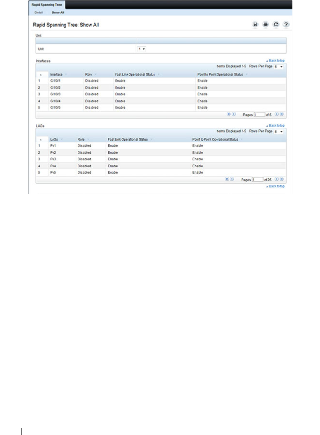
742 Configuring the Spanning Tree Protocol
To view RSTP Settings for all interfaces, click the Show All link. The Rapid
Spanning Tree Table displays.
Figure 22-15. RSTP Settings
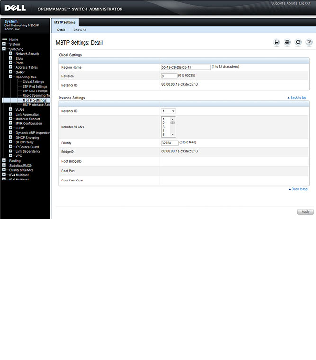
Configuring the Spanning Tree Protocol 743
MSTP Settings
The Multiple Spanning Tree Protocol (MSTP) supports multiple instances of
Spanning Tree to efficiently channel VLAN traffic over different interfaces.
MSTP is compatible with both RSTP and STP; a MSTP bridge can be
configured to behave entirely as a RSTP bridge or a STP bridge.
To display the MSTP Settings page, click Switching
→
Spanning Tree
→
MSTP Settings in the navigation panel.
Figure 22-16. MSTP Settings
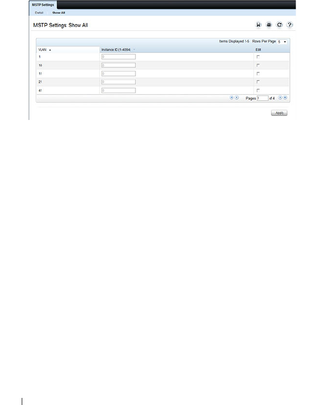
744 Configuring the Spanning Tree Protocol
Viewing and Modifying the Instance ID for Multiple VLANs
To configure MSTP settings for multiple VLANS:
1
Open the
MSTP Settings
page.
2
Click
Show All
to display the
MSTP Settings Table
.
Figure 22-17. Configure MSTP Settings
3
For each Instance ID to modify, select the check box in the
Edit
column in
the row associated with the VLAN.
4
Update the
Instance ID
settings for the selected VLANs.
5
Click
Apply
.
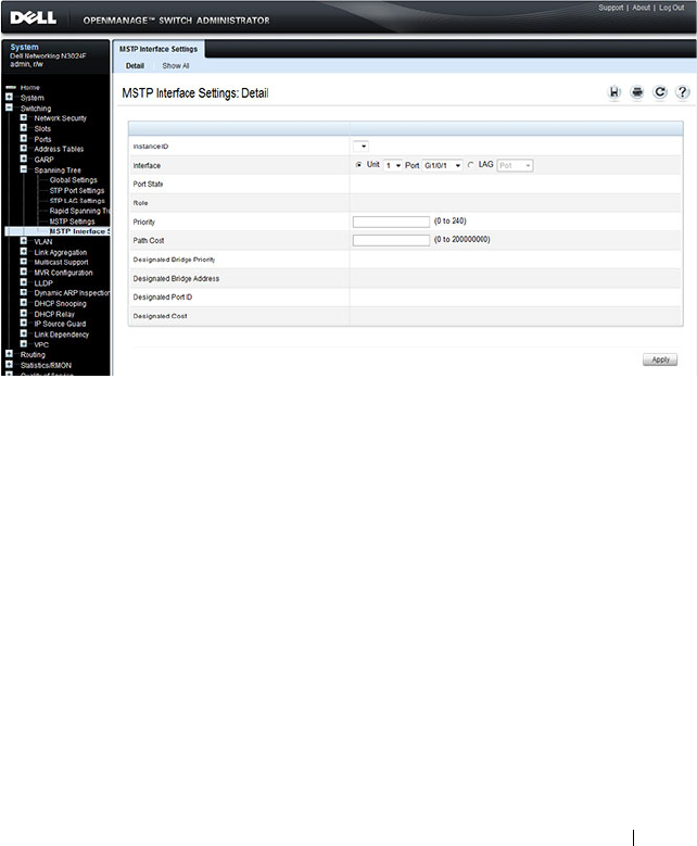
Configuring the Spanning Tree Protocol 745
MSTP Interface Settings
Use the MSTP Interface Settings page to assign MSTP settings to specific
interfaces.
To display the MSTP Interface Settings page, click Switching
→
Spanning
Tree
→
MSTP Interface Settings in the navigation panel.
Figure 22-18. MSTP Interface Settings
Configuring MSTP Settings for Multiple Interfaces
To configure MSTP settings for multiple interfaces:
1
Open the
MSTP Interface Settings
page.
2
Click
Show All
to display the
MSTP Interface
Table
.
3
For each interface to configure, select the check box in the
Edit
column in
the row associated with the interface.
4
Update the desired settings.
5
Click
Apply
.

746 Configuring the Spanning Tree Protocol
Configuring Spanning Tree (CLI)
This section provides information about the commands you use to configure
STP settings on the switch. For more information about the commands, see
the
Dell Networking N2000, N3000, and N4000 Series Switches CLI
Reference Guide
at support.dell.com/manuals.
Configuring Global STP Bridge Settings
Beginning in Privileged EXEC mode, use the following commands to
configure the global STP settings for the switch, such as the priority and
timers.
Command Purpose
configure Enter global configuration mode.
spanning-tree Enable spanning tree on the switch.
spanning tree mode {stp
| rstp |mst}
Specify which spanning tree mode to use on the switch.
spanning-tree priority
priority
Specify the priority of the bridge. (Range: 0–61440). The
switch with the lowest priority value is elected as the root
switch.
spanning-tree max-age
seconds
Specify the switch maximum age time, which indicates the
amount of time in seconds a bridge waits before
implementing a topological change. Valid values are from
(6 to 40) seconds.
spanning-tree forward-
time
seconds
Specify the switch forward delay time, which indicates the
amount of time in seconds a bridge remains in a listening
and learning state before forwarding packets. Valid values
are from (4 to 30) seconds.
spanning-tree max-hops
hops
Configure the maximum number of hops for the Spanning
tree. Valid values are from (6 to 40).
spanning-tree transmit
hold-count [
value
]
Set the maximum number of BPDUs that a bridge is
allowed to send within a hello time window (2 seconds).
The range for
value
is 1–10.
CTRL + Z Exit to Privileged EXEC mode.

Configuring the Spanning Tree Protocol 747
Configuring Optional STP Features
Beginning in Privileged EXEC mode, use the following commands to
configure the optional STP features on the switch or on specific interfaces.
show spanning-tree
[detail] [active |
blockedports]
View information about spanning tree and the spanning
tree configuration on the switch.
Command Purpose
configure Enter global configuration mode.
spanning-tree bpdu
flooding
Allow the flooding of BPDUs received on non-spanning-
tree ports to all other non-spanning-tree ports.
spanning-tree portfast Enable PortFast on all switch ports.
spanning-tree portfast
bpdufilter default
Prevent ports configured in PortFast mode from sending
BPDUs.
spanning-tree loopguard
default
Enable loop guard on all ports.
spanning-tree bpdu-
protection
Enable BPDU protection on the switch.
interface
interface
Enter interface configuration mode for the specified
interface. The
interface
variable includes the interface type
and number, for example tengigabitethernet 1/0/3 or port-
channel 4.
You can also specify a range of interfaces with the interface
range command, for example, interface range
tengigabitethernet 1/0/8-12 configures interfaces 8, 9, 10,
11, and 12. The range keyword is also valid for LAGs (port-
channels).
spanning-tree auto-
portfast
Set the port to auto portfast mode. This enables the port
to become a portfast port if it does not see any BPDUs for
3 seconds.
spanning-tree guard
{root | loop | none}
Enable loop guard or root guard (or disable both) on the
interface.
Command Purpose

748 Configuring the Spanning Tree Protocol
Configuring STP Interface Settings
Beginning in Privileged EXEC mode, use the following commands to
configure the STP settings for a specific interface.
spanning-tree tcnguard Prevent the port from propagating topology change
notifications.
CTRL + Z Exit to Privileged EXEC mode.
show spanning-tree
summary
View various spanning tree settings and parameters for the
switch.
Command Purpose
configure Enter global configuration mode.
interface
interface
Enter interface configuration mode for the specified
interface. The
interface
variable includes the interface type
and number, for example tengigabitethernet 1/0/3 or port-
channel 4.
You can also specify a range of interfaces with the interface
range command, for example, interface range
tengigabitethernet 1/0/8-12 configures interfaces 8, 9, 10,
11, and 12. The range keyword is also valid for LAGs (port-
channels).
spanning-tree disable Disable spanning tree on the port.
spanning-tree port-
priority
priority
Specify the priority of the port. (Range: 0–240).
The priority value is used to determine which ports are put
in the forwarding state and which ports are put in the
blocking state. A port with a lower priority value is more
likely to be put into a forwarding state.
spanning-tree cost
cost
Specify the spanning tree path cost for the port. (Range:
0–200,000,000). The default cost is 0, which signifies that
the cost is automatically calculated based on port speed.
CTRL + Z Exit to Privileged EXEC mode.
show spanning-tree
interface
View spanning tree configuration information for the
specified port or LAG (port-channel).
Command Purpose

Configuring the Spanning Tree Protocol 749
Configuring MSTP Switch Settings
Beginning in Privileged EXEC mode, use the following commands to
configure MSTP settings for the switch.
Command Purpose
configure Enter global configuration mode.
spanning-tree mst
configuration
Enable configuring an MST region by entering the
multiple spanning tree (MST) mode.
name
string
Define the MST configuration name
revision
version
Identify the MST configuration revision number.
instance
instance-id
{add | remove} vlan
vlan-range
Map VLANs to an MST instance.
•
instance-ID —
ID of the MST instance. (Range: 1-4094)
•
vlan-range —
VLANs to be added to the existing MST
instance. To specify a range of VLANs, use a hyphen. To
specify a series of VLANs, use a comma. (Range: 1-4093)
exit Return to global configuration mode.
spanning-tree mst
instance-id
priority
priority
Set the switch priority for the specified spanning tree
instance.
•
instance-id —
ID of the spanning tree instance. (Range:
1-4094)
•
priority —
Sets the switch priority for the specified
spanning tree instance. This setting affects the likelihood
that the switch is selected as the root switch. A lower
value increases the probability that the switch is selected
as the root switch. (Range: 0-61440)
CTRL + Z Exit to Privileged EXEC mode.
show spanning-tree mst-
configuration
View multiple spanning tree configuration information.
show spanning-tree
instance
instance-id
View information about the specified MSTI.

750 Configuring the Spanning Tree Protocol
Configuring MSTP Interface Settings
Beginning in Privileged EXEC mode, use the following commands to
configure MSTP settings for the switch.
Command Purpose
configure Enter global configuration mode.
interface
interface
Enter interface configuration mode for the specified interface.
The
interface
variable includes the interface type and number,
for example tengigabitethernet 1/0/3 or port-channel 4.
You can also specify a range of interfaces with the interface
range command, for example, interface range
tengigabitethernet 1/0/8-12 configures interfaces 8, 9, 10, 11,
and 12. The range keyword is also valid for LAGs (port-
channels).
spanning-tree mst 0
external-cost
cost
Set the external cost for the common spanning tree. (Range:
0–200000000)
spanning-tree mst
instance-id
cost
cost
Configure the path cost for MST calculations. If a loop occurs,
the spanning tree considers path cost when selecting an
interface to put in the forwarding state.
•
instance-ID —
ID of the spanning -tree instance. (Range: 1-
4094)
•
cost —
The port path cost. (Range: 0–200,000,000)
spanning-tree mst
instance-id
port-
priority
priority
Specify the priority of the port.
The priority value is used to determine which ports are put in
the forwarding state and which ports are put in the blocking
state. A port with a lower priority value is more likely to be put
into a forwarding state.
•
instance-ID —
ID of the spanning tree instance. (Range: 1-
4094)
•
priority —
The port priority. (Range: 0–240 in multiples of 16)
CTRL + Z Exit to Privileged EXEC mode.
show spanning-tree
interface
instance
instance-id
View MST configuration information for the specified port or
LAG (port-channel) and instance.

Configuring the Spanning Tree Protocol 751
STP Configuration Examples
This section contains the following examples:
• STP Configuration Example
• MSTP Configuration Example
• RSTP-PV Access Switch Configuration Example
STP Configuration Example
This example shows a LAN with four switches. On each switch, ports 1, 2, and
3 connect to other switches, and ports 4–20 connect to hosts (in Figure 22-19,
each PC represents 17 host systems).
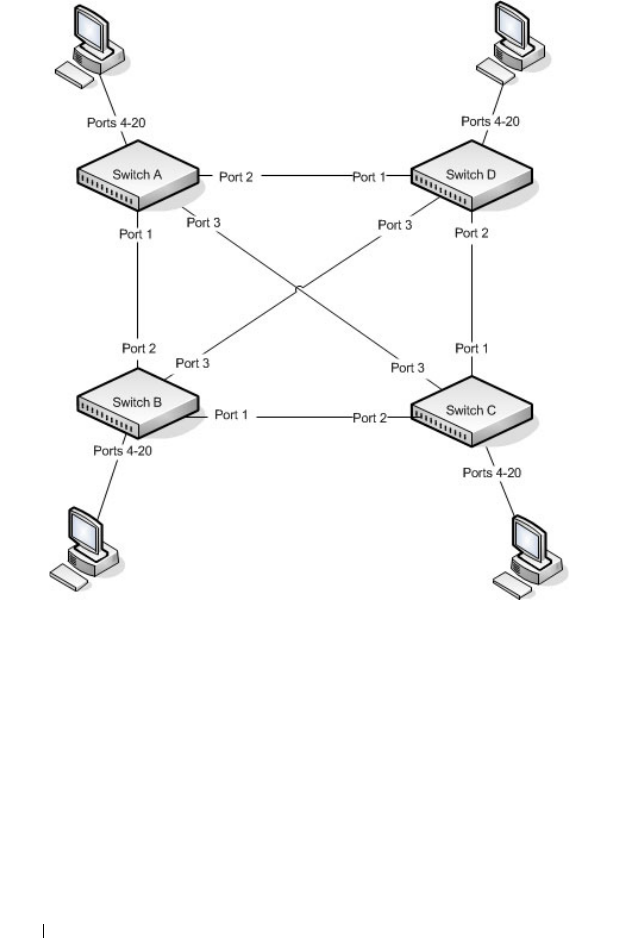
752 Configuring the Spanning Tree Protocol
Figure 22-19. STP Example Network Diagram
Of the four switches in Figure 22-19, the administrator decides that Switch A
is the most centrally located in the network and is the least likely to be moved
or redeployed. For these reasons, the administrator selects it as the root bridge
for the spanning tree. The administrator configures Switch A with the highest
priority and uses the default priority values for Switch B, Switch C, and
Switch D.
For all switches, the administrator also configures ports 4–17 in Port Fast
mode because these ports are connected to hosts and can transition directly
to the Forwarding state to speed up the connection time between the hosts
and the network.

Configuring the Spanning Tree Protocol 753
The administrator also configures Port Fast BPDU filtering and Loop Guard
to extend STP’s capability to prevent network loops. For all other STP
settings, the administrator uses the default STP values.
To configure the switch:
1
Connect to Switch A and configure the priority to be higher (a lower
value) than the other switches, which use the default value of
32768
.
console#config
console(config)#spanning-tree priority 8192
2
Configure ports 4–20 to be in Port Fast mode.
console(config)#interface range gi1/0/4-20
console(config-if)#spanning-tree portfast
console(config-if)#exit
3
Enable Loop Guard on ports 1–3 to help prevent network loops that might
be caused if a port quits receiving BPDUs.
console(config)#interface range gi1/0/1-3
console(config-if)#spanning-tree guard loop
console(config-if)#exit
4
Enable Port Fast BPDU Filter. This feature is configured globally, but it
affects only Port Fast-enabled access ports.
console(config)#spanning-tree portfast bpdufilter
default
5
Repeat step 2 through step 4 on Switch B, Switch C, and Switch D to
complete the configuration.
MSTP Configuration Example
This example shows how to configure IEEE 802.1s Multiple Spanning Tree
(MST) protocol on the switches shown in Figure 22-20.
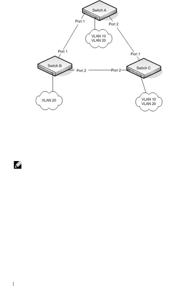
754 Configuring the Spanning Tree Protocol
Figure 22-20. MSTP Configuration Example
To make multiple switches be part of the same MSTP region, make sure the
STP operational mode for all switches is MSTP. Also, make sure the MST
region name and revision level are the same for all switches in the region.
To configure the switches:
1
Create VLAN 10 (Switch A and Switch B) and VLAN 20 (all switches).
console#configure
console(config)#vlan 10,20
console(config-vlan10,20)#exit
console(config-vlan)#exit
2
Set the STP operational mode to MSTP.
console(config)#spanning-tree mode mst
3
Create MST instance 10 and associate it to VLAN 10.
console(config)#spanning-tree mst configuration
NOTE: Even Switch B does not have any ports that are members of VLAN 10,
this VLAN must be created to allow the formation of MST regions made up of
all bridges that exchange the same MST Configuration Identifier. It is only
within these MST Regions that multiple instances can exist.

Configuring the Spanning Tree Protocol 755
console(config-mst)#instance 10 add vlan 10
4
Create MST instances 20 and associate it to VLAN 20.
console(config-mst)#instance 20 add vlan 20
5
Change the region name so that all the bridges that want to be part of the
same region can form the region.
console(config-mst)#name dell
console(config-mst)#exit
6
(Switch A only) Configure Switch A to be the root bridge of the spanning
tree (CIST Regional Root) by configuring a higher root bridge priority.
console(config)#spanning-tree priority 8192
7
(Switch A only) Make Switch A the Regional Root for MSTI 1 by
configuring a higher priority for MST ID 10.
console(config)#spanning-tree mst 10 priority
12288
8
(Switch A only) Change the priority of MST ID 20 to ensure Switch C is
the Regional Root bridge for this MSTI.
console(config)#spanning-tree mst 20 priority
61440
console(config)#spanning-tree priority 8192
9
(Switch C only) Change the priority of port 1 to force it to be the root port
for MST 20.
console(config)#interface gi1/0/1
console(config-if-Gi1/0/1)#spanning-tree mst 20
port-priority 64
console(config-if-Gi1/0/1)#exit

756 Configuring the Spanning Tree Protocol
RSTP-PV Access Switch Configuration Example
In this configuration, all 1G ports are presumed to be connected to host
machines, and the two 10G uplink ports are connected to an aggregation-
layer switch with a total L2 network diameter of 4. The aggregation-layer
switch can be a single switch or multiple switches, running either RSTP-PV or
MSTP. For fastest convergence during failover scenarios, it is recommended
that the uplink switches be configured in RSTP-PV mode.
Three VLANs are configured in addition to VLAN 1. Te1/0/1 is configured to
be the primary uplink port and Te1/0/2 is configured to be the backup uplink.
1
Configure VLANs 2 through 4 and return to Global Config mode.
console#configure
console(config)#vlan 2-4
console(config-vlan2-4)#exit
2
Enable RSTP-PV.
console(config)#spanning-tree mode rapid-pvst
3
Configure for a maximum network diameter of 4.
console(config)#spanning-tree vlan 1-4 max-age 16
4
Configure access and trunk ports
console(config)#interface range gi1/0/1-48
console(config-if)#switchport mode access
console(config-if)exit
console(config)#interface range te1/0/1-2
console(config-if)#switchport mode trunk
console(config-if)#exit
5
Configure interface te1/0/1 as the preferred uplink.
console(config)#interface te1/0/1
console(config-if)#spanning-tree port-priority 112
console(config-if)#exit
6
Assign ports to VLANs.
console(config)#interface range gi1/0/1-12
console(config-if)#switchport access vlan 1
console(config-if)#exit
console(config)#interface range gi1/0/1-12
console(config-if)#switchport access vlan 2

Configuring the Spanning Tree Protocol 757
console(config-if)#exit
console(config)#interface range gi1/0/1-12
console(config-if)#switchport access vlan 3
console(config-if)#exit
console(config)#interface range gi1/0/1-12
console(config-if)#switchport access vlan 4
console(config-if)#exit

758 Configuring the Spanning Tree Protocol
RSTP-PV Aggregation Layer Switch Configuration Example
In this configuration example, two aggregation-layer switches are configured.
Ports 1–4 are configured in a LAG connecting the two aggregation-layer
switches. Ports 12–24 are configured as down-links to twelve access layer
switches configured as in the previous example. Down-links to the access-
layer switches have physical diversity; there is one downlink to each of the
twelve access-layer switches from each of the paired aggregation-layer
switches.
The uplink ports to the network core are configured as LAGs to provide link
redundancy. It is presumed that the core links connect to a router running
RSTP-PV. The configuration for the two aggregation-layer switches is
identical, except for the diversity configuration noted below.
For forwarding diversity, the even numbered switch is made the root for the
even-numbered VLANs. The odd numbered switch is made the root for the
odd-numbered VLANs.
1
Create VLANs 2 through 4:
console#configure
console(config)#vlan 2-4
console(config-vlan2-4)#exit
2
Enable RSTP-PV:
console(config)#spanning-tree mode rapid-pvst
3
Configure for a max network diameter of 4:
console(config)#spanning-tree vlan 1-4 max-age 16
4
Configure one downlink trunk port per downlink switch:
console(config)#interface range te1/0/12-24
console(config-if-Te1/0/12-24)#switchport mode
trunk
exit
5
Configure forwarding diversity for the even numbered switches:
console(config)#spanning-tree vlan 2,4 root
primary
console(config)#spanning-tree vlan 1,3 root
secondary
6
Configure forwarding diversity for the odd numbered switches:

Configuring the Spanning Tree Protocol 759
console(config)#spanning-tree vlan 1,3 root
primary
console(config)#spanning-tree vlan 2,4 root
secondary
7
Configure two uplink ports per uplink switch:
console(config)#interface range fo1/0/1-2
console(config-if-fo1/0/1-2)#channel-group 1 mode
active
console(config-if-fo1/0/1-2)#exit
8
Configure peer switch links:
console(config)#interface range te1/0/1-4
console(config-if-te1/0/1-4)#channel-group 2 mode
active
console(config-if-te1/0/1-4)#exit
9
Configure the uplinks into a port channel:
console(config)#interface port-channel 1
console(config-if-port-channel 1)#switchport mode
trunk
console(config-if-port-channel 1)#exit
10
Configure the peer links into a port channel and prefer to go to the core
router or access switches directly, i.e. block the peer link unless it is needed:
console(config)#interface port-channel 1
console(config-if-port-channel 1)#switchport mode
trunk
console(config-if-port-channel 1)#spanning-tree
port-priority 144
console(config-if-port-channel 1)#exit

760 Configuring the Spanning Tree Protocol

Discovering Network Devices 761
23
Discovering Network Devices
This chapter describes the Industry Standard Discovery Protocol (ISDP)
feature and the Link Layer Discovery Protocol (LLDP) feature, including
LLDP for Media Endpoint Devices (LLDP-MED).
The topics covered in this chapter include:
• Device Discovery Overview
• Default IDSP and LLDP Values
• Configuring ISDP and LLDP (Web)
• Configuring ISDP and LLDP (CLI)
• Device Discovery Configuration Examples
Device Discovery Overview
The switch software includes two different device discovery protocols: IDSP
and LLDP. These protocols allow the switch to broadcast information about
itself and to learn information about neighboring devices.
What Is ISDP?
The Industry Standard Discovery Protocol (ISDP) is a proprietary Layer 2
network protocol that inter-operates with Cisco devices running the Cisco
Discovery Protocol (CDP). ISDP is used to share information between
neighboring devices. The switch software participates in the CDP protocol
and is able to both discover and be discovered by other CDP-supporting
devices.
What is LLDP?
LLDP is a standardized discovery protocol defined by IEEE 802.1AB. It allows
stations residing on an 802 LAN to advertise major capabilities physical
descriptions, and management information to physically adjacent devices
allowing a network management system (NMS) to access and display this
information.

762 Discovering Network Devices
LLDP is a one-way protocol; there are no request/response sequences.
Information is advertised by stations implementing the transmit function,
and is received and processed by stations implementing the receive function.
The transmit and receive functions can be enabled/disabled separately on
each switch port.
What is LLDP-MED?
LLDP-MED is an extension of the LLDP standard. LLDP-MED uses LLDP's
organizationally-specific Type- Length-Value (TLV) extensions and defines
new TLVs that make it easier for a VoIP deployment in a wired or wireless
LAN/MAN environment. It also makes mandatory a few optional TLVs from
LLDP and recommends not transmitting some TLVs.
The TLVs only communicate information; these TLVs do not automatically
translate into configuration. An external application may query the MED
MIB and take management actions in configuring functionality.
Why are Device Discovery Protocols Needed?
The device discovery protocols are used primarily in conjunction with
network management tools to provide information about network topology
and configuration, and to help troubleshoot problems that occur on the
network. The discovery protocols can also facilitate inventory management
within a company.
LLDP and the LLDP-MED extension are vendor-neutral discovery protocols
that can discover devices made by numerous vendors. LLDP-MED is
intended to be used on ports that connect to VoIP phones. Additional
applications for LLDP-MED include device location (including for
Emergency Call Service/E911) and Power over Ethernet management.
ISDP interoperates with the Cisco-proprietary CDP protocol and is most
effective in an environment that contains many Cisco devices.

Discovering Network Devices 763
Default IDSP and LLDP Values
ISDP and LLDP are globally enabled on the switch and enabled on all ports
by default. By default, the switch transmits and receives LLDP information
on all ports. LLDP-MED is disabled on all ports.
Table 23-1 summarizes the default values for ISDP.
Table 23-2 summarizes the default values for LLDP.
Table 23-1. ISDP Defaults
Parameter Default Value
ISDP Mode Enabled (globally and on all ports)
ISDPv2 Mode Enabled (globally and on all ports)
Message Interval 30 seconds
Hold Time Interval 180 seconds
Device ID none
Device ID Format Capability Serial Number, Host Name
Device ID Format Serial Number
Table 23-2. LLDP Defaults
Parameter Default Value
Transmit Mode Enabled on all ports
Receive Mode Enabled on all ports
Transmit Interval 30 seconds
Hold Multiplier 4
Reinitialization Delay 2 seconds
Notification Interval 5 seconds
Transmit Management Information Disabled
Notification Mode Disabled
Included TLVs None

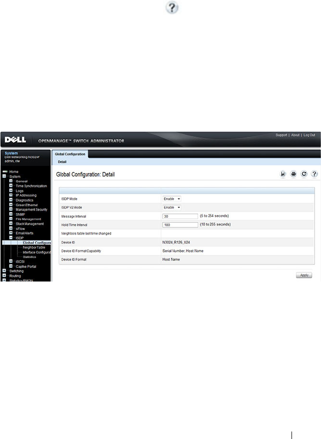
Discovering Network Devices 765
Configuring ISDP and LLDP (Web)
This section provides information about the OpenManage Switch
Administrator pages for configuring and monitoring IDSP and LLDP/LLDP-
MED on a Dell Networking N2000, N3000, and N4000 series switches. For
details about the fields on a page, click at the top of the page.
ISDP Global Configuration
From the ISDP Global Configuration page, you can configure the ISDP
settings for the switch, such as the administrative mode.
To access the ISDP Global Configuration page, click System
→
ISDP
→
Global Configuration in the navigation panel.
Figure 23-1. ISDP Global Configuration
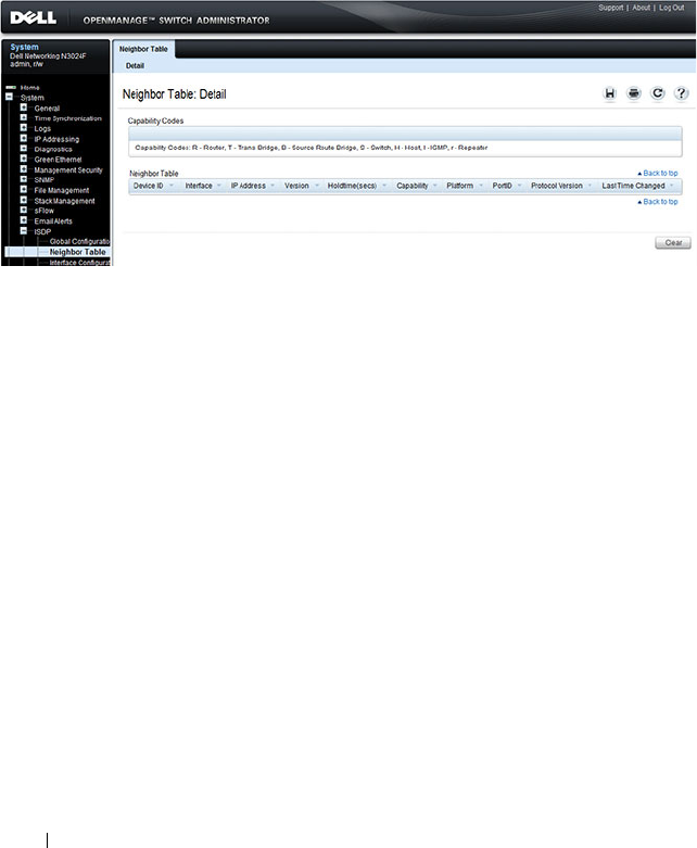
766 Discovering Network Devices
ISDP Cache Table
From the ISDP Neighbor Table page, you can view information about other
devices the switch has discovered through the ISDP.
To access the ISDP Neighbor Table page, click System
→
ISDP
→
Neighbor
Ta bl e in the navigation panel.
Figure 23-2. ISDP Neighbor Table
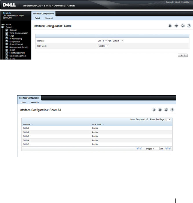
Discovering Network Devices 767
ISDP Interface Configuration
From the ISDP Interface Configuration page, you can configure the ISDP
settings for each interface.
If ISDP is enabled on an interface, it must also be enabled globally in order
for the interface to transmit ISDP packets. If the ISDP mode on the ISDP
Global Configuration page is disabled, the interface will not transmit ISDP
packets, regardless of the mode configured on the interface.
To access the ISDP Interface Configuration page, click System
→
ISDP
→
Interface Configuration in the navigation panel.
Figure 23-3. ISDP Interface Configuration
To view view the ISDP mode for multiple interfaces, click Show All.
Figure 23-4. ISDP Interface Summary
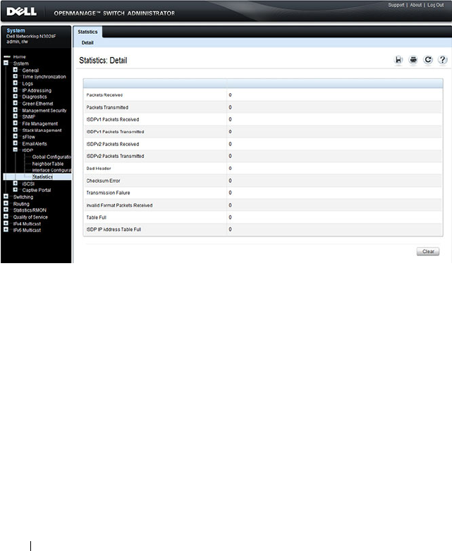
768 Discovering Network Devices
ISDP Statistics
From the ISDP Statistics page, you can view information about the ISDP
packets sent and received by the switch.
To access the ISDP Statistics page, click System
→
ISDP
→
Statistics in the
navigation panel.
Figure 23-5. ISDP Statistics

Discovering Network Devices 769
LLDP Configuration
Use the LLDP Configuration page to specify LLDP parameters. Parameters
that affect the entire system as well as those for a specific interface can be
specified here.
To display the LLDP Configuration page, click Switching
→
LLDP
→
Configuration in the navigation panel.
Figure 23-6. LLDP Configuration
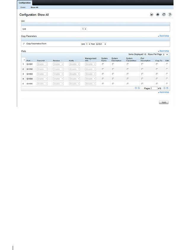
770 Discovering Network Devices
To view the LLDP Interface Settings Table, click Show All. From the LLDP
Interface Settings Table page, you can view and edit information about the
LLDP settings for multiple interfaces.
Figure 23-7. LLDP Interface Settings Table

Discovering Network Devices 771
LLDP Statistics
Use the LLDP Statistics page to view LLPD-related statistics.
To display the LLDP Statistics page, click Switching
→
LLDP
→
Statistics
in the navigation panel.
Figure 23-8. LLDP Statistics
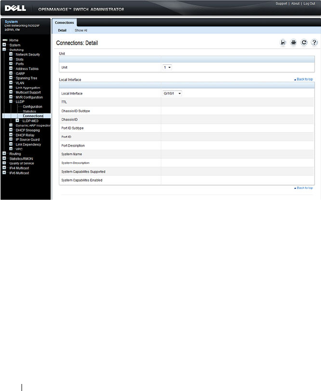
772 Discovering Network Devices
LLDP Connections
Use the LLDP Connections page to view the list of ports with LLDP
enabled. Basic connection details are displayed.
To display the LLDP Connections page, click Switching
→
LLDP
→
Connections in the navigation panel.
Figure 23-9. LLDP Connections
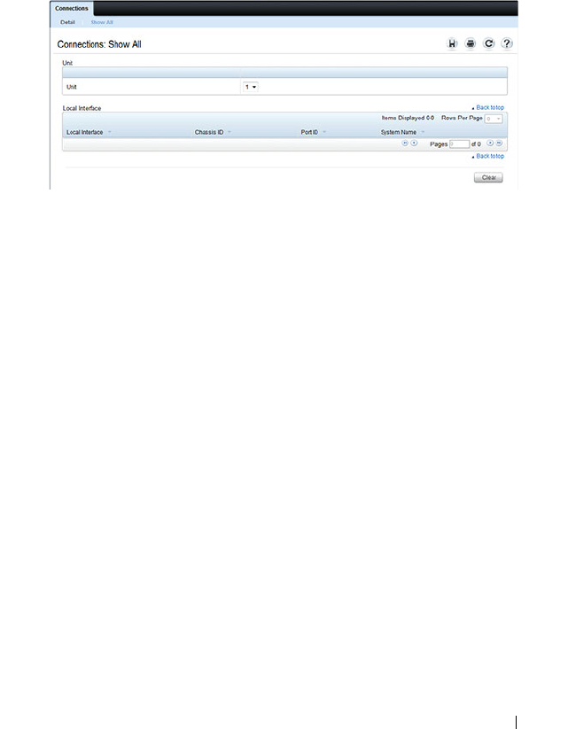
Discovering Network Devices 773
To view additional information about a device connected to a port that has
been discovered through LLDP, click the port number in the Local Interface
table (it is a hyperlink), or click Details and select the port with the
connected device.
Figure 23-10. LLDP Connection Detail
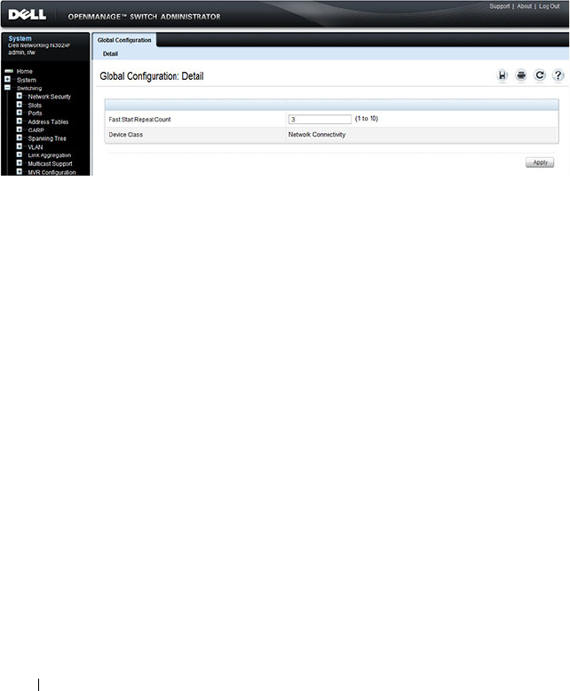
774 Discovering Network Devices
LLDP-MED Global Configuration
Use the LLDP-MED Global Configuration page to change or view the
LLDP-MED parameters that affect the entire system.
To display the LLDP-MED Global Configuration page, click Switching
→
LLDP
→
LLDP-MED
→
Global Configuration in the navigation panel.
Figure 23-11. LLDP-MED Global Configuration
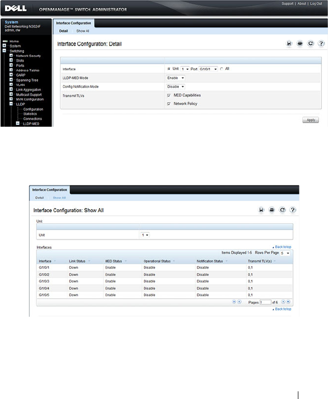
Discovering Network Devices 775
LLDP-MED Interface Configuration
Use the LLDP-MED Interface Configuration page to specify LLDP-MED
parameters that affect a specific interface.
To display the LLDP-MED Interface Configuration page, click Switching
→
LLDP
→
LLDP-MED
→
Interface Configuration in the navigation panel.
Figure 23-12. LLDP-MED Interface Configuration
To view the LLDP-MED Interface Summary table, click Show All.
Figure 23-13. LLDP-MED Interface Summary

776 Discovering Network Devices
LLDP-MED Local Device Information
Use the LLDP-MED Local Device Information page to view the advertised
LLDP local data for each port.
To display the LLDP-MED Local Device Information page, click
Switching
→
LLDP
→
LLDP-MED
→
Local Device Information in the
navigation panel.
Figure 23-14. LLDP-MED Local Device Information
LLDP-MED Remote Device Information
Use the LLDP-MED Remote Device Information page to view the
advertised LLDP data advertised by remote devices.
To display the LLDP-MED Remote Device Information page, click
Switching
→
LLDP
→
LLDP-MED
→
Remote Device Information in the
navigation panel.
Figure 23-15. LLDP-MED Remote Device Information

Discovering Network Devices 777
Configuring ISDP and LLDP (CLI)
This section provides information about the commands you use to manage
and view the device discovery protocol features on the switch. For more
information about these commands, see the
Dell Networking N2000, N3000,
and N4000 Series Switches CLI Reference Guide
at
support.dell.com/manuals.
Configuring Global ISDP Settings
Beginning in Privileged EXEC mode, use the following commands to
configure ISDP settings that affect the entire switch.
Command Purpose
configure Enter Global Configuration mode.
isdp enable Administratively enable ISDP on the switch.
isdp advertise-v2 Allow the switch to send ISDPv2 packets.
isdp holdtime
time
Specify the number of seconds the device that receives
ISDP packets from the switch should store information
sent in the ISDP packet before discarding it.
isdp timer
time
Specify the number of seconds to wait between sending
new ISDP packets.
exit Exit to Privileged EXEC mode.
show isdp View global ISDP settings.

778 Discovering Network Devices
Enabling ISDP on a Port
Beginning in Privileged EXEC mode, use the following commands to enable
ISDP on a port.
Viewing and Clearing ISDP Information
Beginning in Privileged EXEC mode, use the following commands to view
and clear the contents of the ISDP table and to view and clear ISDP statistics.
Command Purpose
configure Enter Global Configuration mode.
interface
interface
Enter interface configuration mode for the specified
interface.
isdp enable Administratively enable ISDP on the switch.
exit Exit to Global Config mode.
exit Exit to Privileged Exec mode.
show isdp interface all View the ISDP mode on all interfaces.
Command Purpose
show isdp entry {all |
deviceid
}
View information about all entries or a specific entry in the
ISDP table.
show isdp neighbors View the neighboring devices discovered through ISDP.
clear isdp table Clear all entries, including discovered neighbors, from the
ISDP table.
show isdp traffic View ISDP statistics.
clear isdp counters Reset all ISDP statistics to zero.

Discovering Network Devices 779
Configuring Global LLDP Settings
Beginning in Privileged EXEC mode, use the following commands to
configure LLDP settings that affect the entire switch.
Configuring Port-based LLDP Settings
Beginning in Privileged EXEC mode, use the following commands to
configure per-port LLDP settings.
Command Purpose
configure Enter Global Configuration mode.
lldp notification-
interval
interval
Specify how often, in seconds, the switch should send
remote data change notifications.
lldp timers [interval
transmit-interval
] [hold
hold-value
] [reinit
reinit-
delay
]
Configure the timing for local data transmission on ports
enabled for LLDP.
•
transmit-interval —
The interval in seconds at which to
transmit local data LLDP PDUs. (Range: 5–32768
seconds)
•
hold-value —
Multiplier on the transmit interval used to
set the TTL in local data LLDP PDUs. (Range: 2–10)
•
reinit-delay —
The delay in seconds before re-
initialization. (Range: 1–10 seconds)
exit Exit to Privileged EXEC mode.
show lldp View global LLDP settings.
Command Purpose
configure Enter Global Configuration mode.
interface
interface
Enter interface configuration mode for the specified
Ethernet interface.
lldp transmit Enable the LLDP advertise (transmit) capability.
lldp receive Enable the LLDP receive capability so that the switch can
receive LLDP Protocol Data Units (LLDP PDUs) from
other devices.
lldp transmit-mgmt Include the transmission of local system management
address information in the LLDP PDUs.

780 Discovering Network Devices
Viewing and Clearing LLDP Information
Beginning in Privileged EXEC mode, use the following commands to view
transmitted and received LLDP information and to view and clear LLDP
statistics.
lldp notification Enable remote data change notifications on the interface.
lldp transmit-tlv [sys-
desc][sys-name][sys-
cap][port-desc]
Specify which optional type-length-value settings (TLVs)
in the 802.1AB basic management set will be transmitted
in the LLDP PDUs.
• sys-name — Transmits the system name TLV
• sys-desc — Transmits the system description TLV
• sys-cap — Transmits the system capabilities TLV
• port desc — Transmits the port description TLV
exit Exit to Global Config mode.
exit Exit to Privileged EXEC mode.
show lldp interface all View LLDP settings for all interfaces.
Command Purpose
show lldp local-device
{all |
interface
| detail
interface
}
View LLDP information advertised by all ports or the
specified port. Include the keyword detail to see additional
information.
show lldp remote-device
{all |
interface
| detail
interface
}
View LLDP information received by all ports or by the
specified port. Include the keyword detail to see additional
information.
clear lldp remote-data Delete all LLDP information from the remote data table.
show lldp statistics View LLDP traffic statistics.
clear lldp statistics Reset the LLDP statistics counters to zero.
Command Purpose

Discovering Network Devices 781
Configuring LLDP-MED Settings
Beginning in Privileged EXEC mode, use the following commands to
configure LLDP-MED settings that affect the entire switch.
Command Purpose
configure Enter Global Configuration mode.
lldp med
faststartrepeatcount
count
Specifies the number of LLDP PDUs that will be
transmitted when the protocol is enabled.
interface
interface
Enter interface configuration mode for the specified
Ethernet interface.
lldp med Enable LLDP-MED on the interface.
lldp med
confignotification
Allow the port to send topology change notifications.
lldp med transmit-tlv
[capabilities] [network-
policy] [location]
[inventory]
Specify which optional TLVs in the LLDP MED set are
transmitted in the LLDP PDUs.
exit Exit to Global Config mode.
exit Exit to Privileged EXEC mode.
show lldp med View global LLDP-MED settings.
show lldp med interface
{all |
interface
}
View LLDP-MED settings for all ports or for the specified
port.

782 Discovering Network Devices
Viewing LLDP-MED Information
Beginning in Privileged EXEC mode, use the following commands to view
information about the LLDP-MED Protocol Data Units (PDUs) that are sent
and have been received.
Device Discovery Configuration Examples
This section contains the following examples:
• Configuring ISDP
• Configuring LLDP
Configuring ISDP
This example shows how to configure ISDP settings on the switch.
To configure the switch:
1
Specify the number of seconds that a remote device should keep the ISDP
information sent by the switch before discarding it.
console#configure
console(config)#isdp holdtime 60
2
Specify how often, in seconds, the ISDP-enabled ports should transmit
information.
console(config)#isdp timer 45
3
Enable ISDP on interface 1/0/3.
console(config)#interface tengigabitEthernet1/0/3
console(config-if-Te1/0/3)#isdp enable
4
Exit to Privileged EXEC mode and view the LLDP settings for the switch
and for interface 1/0/3.
console(config-if-Te1/0/3)# <CTRL + Z>
Command Purpose
show lldp med local-
device detail
interface
View LLDP information advertised by the specified port.
show lldp remote-device
{all |
interface
| detail
interface
}
View LLDP-MED information received by all ports or by
the specified port. Include the keyword detail to see
additional information.

Discovering Network Devices 783
console#show isdp
Timer....................................45
Hold Time................................60
Version 2 Advertisements.................Enabled
Neighbors table time since last change...00 days 00:00:00
Device ID................................none
Device ID format capability..............Serial Number, Host Name
Device ID format.........................Serial Number
console#show isdp interface te1/0/3
Interface Mode
--------------- ----------
Te1/0/3 Enabled
Configuring LLDP
This example shows how to configure LLDP settings for the switch and to
allow 10-Gigabit Ethernet port 1/0/3 to transmit all LLDP information
available.
To configure the switch:
1
Configure the transmission interval, hold multiplier, and reinitialization
delay for LLDP PDUs sent from the switch.
console#configure
console(config)#lldp timers interval 60 hold 5
reinit 3
2
Enable port 1/0/3 to transmit and receive LLDP PDUs.
console(config)#interface TengigabitEthernet1/0/3
console(config-if-Te1/0/3)#lldp transmit
console(config-if-Te1/0/3)#lldp receive
3
Enable port 1/0/3 to transmit management address information in the
LLDP PDUs and to send topology change notifications if a device is added
or removed from the port.
console(config-if-Te1/0/3)#lldp transmit-mgmt
console(config-if-Te1/0/3)#lldp notification
4
Specify the TLV information to be included in the LLDP PDUs
transmitted from port 1/0/3.
console(config-if-Te1/0/3)#lldp transmit-tlv sys-
name sys-desc sys-cap port-desc
5
Set the port description to be transmitted in LLDP PDUs.

784 Discovering Network Devices
console(config-if-Te1/0/3)#description “Test Lab
Port”
6
Exit to Privileged EXEC mode.
console(config-if-Te1/0/3)# <CTRL + Z>
7
View global LLDP settings on the switch.
console#show lldp
LLDP Global Configuration
Transmit Interval..................... 60 seconds
Transmit Hold Multiplier.............. 5
Reinit Delay.......................... 3 seconds
Notification Interval................. 5 seconds
8
View summary information about the LLDP configuration on port 1/0/3.
console#show lldp interface te1/0/3
LLDP Interface Configuration
Interface Link Transmit Receive Notify TLVs Mgmt
--------- ------ -------- -------- -------- ------- ----
Te1/0/3 Down Enabled Enabled Enabled 0,1,2,3 Y
TLV Codes: 0- Port Description, 1- System Name
2- System Description, 3- System Capabilities
9
View detailed information about the LLDP configuration on port 1/0/3.
console#show lldp local-device detail te1/0/3
LLDP Local Device Detail
Interface: Te1/0/3
Chassis ID Subtype: MAC Address
Chassis ID: 00:1E:C9:AA:AA:07
Port ID Subtype: Interface Name
Port ID: Te1/0/3
System Name: console
System Description: Dell Networking N3048

Discovering Network Devices 785
Port Description: Test Lab Port
System Capabilities Supported: bridge, router
System Capabilities Enabled: bridge
Management Address:
Type: IPv4
Address: 192.168.2.1

786 Discovering Network Devices

Configuring Port-Based Traffic Control 787
24
Configuring Port-Based Traffic
Control
This chapter describes how to configure features that provide traffic control
through filtering the type of traffic or limiting the speed or amount of traffic
on a per-port basis. The features this section describes includes flow control,
storm control, protected ports, and Link Local Protocol Filtering (LLPF),
which is also known as Cisco Protocol Filtering.
The topics covered in this chapter include:
• Port-Based Traffic Control Overview
• Default Port-Based Traffic Control Values
• Configuring Port-Based Traffic Control (Web)
• Configuring Port-Based Traffic Control (CLI)
• Port-Based Traffic Control Configuration Example
Port-Based Traffic Control Overview
Table 24-1 provides a summary of the features this chapter describes.
Table 24-1. Port-Based Traffic Control Features
Feature Description
Flow control Allows traffic transmission between a switch port and another
Ethernet device to be paused for a specified period of time when
congestion occurs.
Storm control Limits the amount of broadcast, unknown unicast, and multicast
frames accepted and forwarded by the switch.
Protected ports Prevents traffic from flowing between members of the same
protected port group.
LLPF Filters proprietary protocols that should not normally be relayed
by a bridge.

788 Configuring Port-Based Traffic Control
The Priority Flow Control (PFC) feature, which is available on the N4000
switches only, provides a way to distinguish which traffic on a physical link is
paused when congestion occurs based on the priority of the traffic. For more
information, see "Configuring Data Center Bridging Features" on page 983.
What is Flow Control?
IEEE 802.3 Annex 31B flow control allows nodes that transmit at slower
speeds to communicate with higher speed switches by requesting that the
higher speed switch refrain from sending packets. Transmissions are
temporarily halted to prevent buffer overflows. Enabling the flow control
feature allows Dell Networking series switches to process pause frames
received from connected devices. Dell Networking switches do not transmit
pause frames.
Flow control is supported only on ports that are configured for full-duplex
mode of operation.
What is Storm Control?
A LAN storm is the result of an excessive number of broadcast, multicast, or
unknown unicast messages simultaneously transmitted across a network by a
single port. Forwarded message responses can overload network resources and
cause network congestion.
The storm control feature allows the switch to measure the incoming
broadcast, multicast, and/or unknown unicast packet rate per port and discard
packets when the rate exceeds the defined threshold. Storm control is enabled
per interface, by defining the packet type and the rate at which the packets
are transmitted. For each type of traffic (broadcast, multicast, or unknown
unicast) you can configure a threshold level, which is expressed as a
percentage of the total available bandwidth on the port. If the ingress rate of
that type of packet is greater than the configured threshold level the port
drops the excess traffic until the ingress rate for the packet type falls below
the threshold.
The actual rate of ingress traffic required to activate storm-control is based on
the size of incoming packets and the hard-coded average packet size of 512
bytes - used to calculate a packet-per-second (pps) rate - as the forwarding-
plane requires PPS versus an absolute rate Kbps. For example, if the

Configuring Port-Based Traffic Control 789
configured limit is 10%, this is converted to ~25000 PPS, and this PPS limit
is set in the hardware. You get the approximate desired output when 512 bytes
packets are used.
What are Protected Ports?
The switch supports up to three separate groups of protected ports. Traffic
can flow between protected ports belonging to different groups, but not
within the same group.
A port can belong to only one protected port group. You must remove an
interface from one group before adding it to another group.
Port protection occurs within a single switch. Protected port configuration
does not affect traffic between ports on two different switches. No traffic
forwarding is possible between two protected ports.
What is Link Local Protocol Filtering?
The Link Local Protocol Filtering (LLPF) feature can help troubleshoot
network problems that occur when a network includes proprietary protocols
running on standards-based switches. LLPF allows Dell Networking N2000,
N3000, and N4000 series switches to filter out various Cisco proprietary
protocol data units (PDUs) and/or ISDP packets if problems occur with these
protocols running on standards-based switches. If certain protocol PDUs
cause unexpected results, LLPF can be enabled to prevent those PDUs from
being processed by the switch.
The LLPF feature can be configured per-port to block any combination (or
all) of the following PDUs:
• Industry Standard Discovery Protocol (ISDP)
• VLAN Trunking Protocol (VTP)
• Dynamic Trunking Protocol (DTP)
• UniDirectional Link Detection (UDLD)
• Port Aggregation Protocol (PAgP)
• Shared Spanning Tree Protocol (SSTP)

790 Configuring Port-Based Traffic Control
Access Control Lists (ACLs) and LLPF can exist on the same interface.
However, the ACL rules override the LLPF rules when there is a conflict.
Similarly, DiffServ and LLPF can both be enabled on an interface, but
DiffServ rules override LLPF rules when there is a conflict.
If Industry Standard Discovery Protocol (ISDP) is enabled on an interface,
and the LLPF feature on an interface is enabled and configured to drop ISDP
PDUs, the ISDP configuration overrides the LLPF configuration, and the
ISDP PDUs are allowed on the interface.
Default Port-Based Traffic Control Values
Table 24-2 lists the default values for the port-based traffic control features
that this chapter describes.
Table 24-2. Default Port-Based Traffic Control Values
Feature Default
Flow control Enabled
Storm control Disabled
Protected ports None
LLPF No protocols are blocked
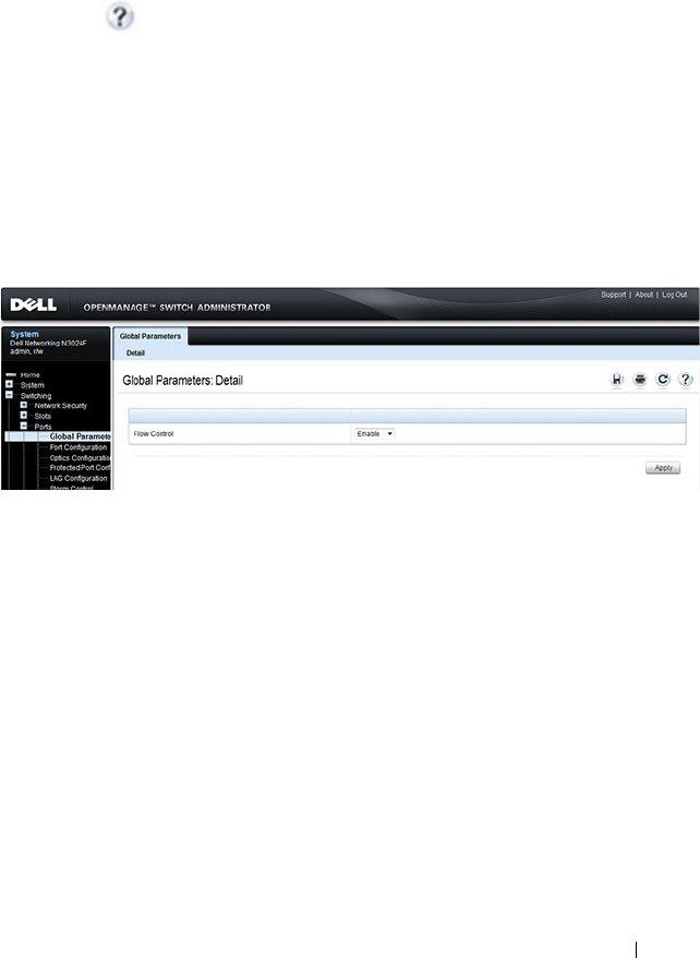
Configuring Port-Based Traffic Control 791
Configuring Port-Based Traffic Control (Web)
This section provides information about the OpenManage Switch
Administrator pages to use to control port-based traffic on a Dell Networking
N2000, N3000, and N4000 series switches. For details about the fields on a
page, click at the top of the page.
Flow Control (Global Port Parameters)
Use the Global Parameters page for ports to enable or disable flow control
support on the switch.
To display the Global Parameters page, click Switching
→
Ports
→
Global
Parameters in the navigation menu.
Figure 24-1. Global Port Parameters
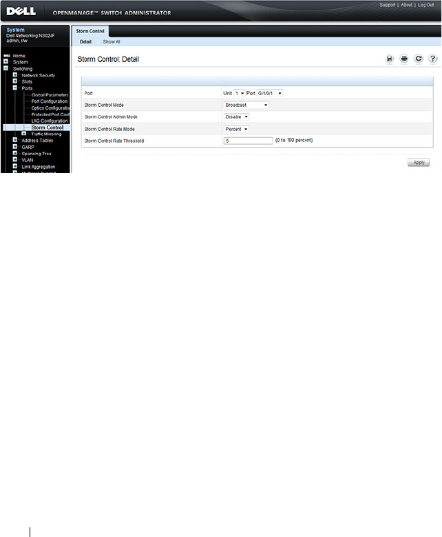
792 Configuring Port-Based Traffic Control
Storm Control
Use the Storm Control page to enable and configure the storm control
feature.
To display the Storm Control interface, click Switching
→
Ports
→
Storm
Control in the navigation menu.
Figure 24-2. Storm Control
Configuring Storm Control Settings on Multiple Ports
To configure storm control on multiple ports:
1
Open the
Storm Control
page.
2
Click
Show All
to display the
Storm Control Settings Table
.
3
In the Ports list, select the check box in the
Edit
column for the port to
configure.
4
Select the desired storm control settings.
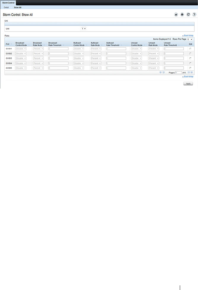
Configuring Port-Based Traffic Control 793
Figure 24-3. Storm Control
5
Click
Apply
.
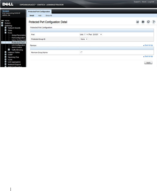
794 Configuring Port-Based Traffic Control
Protected Port Configuration
Use the Protected Port Configuration page to prevent ports in the same
protected ports group from being able to see each other’s traffic.
To display the Protected Port Configuration page, click Switching
→
Ports
→
Protected Port Configuration in the navigation menu.
Figure 24-4. Protected Port Configuration
Configuring Protected Ports
To configure protected ports:
1
Open the
Protected Ports
page.
2
Click
Add
to display the
Add Protected Group
page.
3
Select a group (0–2).
4
Specify a name for the group.
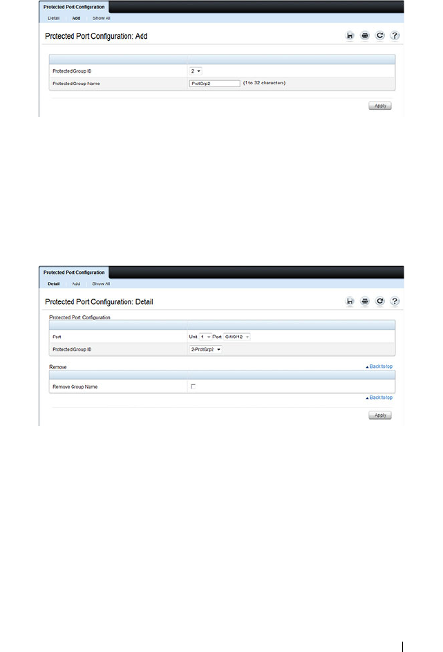
Configuring Port-Based Traffic Control 795
Figure 24-5. Add Protected Ports Group
5
Click
Apply
.
6
Click
Protected Port Configuration to return to the main page.
7
Select the port to add to the group.
8
Select the protected port group ID.
Figure 24-6. Add Protected Ports
9
Click
Apply
.
10
To view protected port group membership information, click
Show All
.
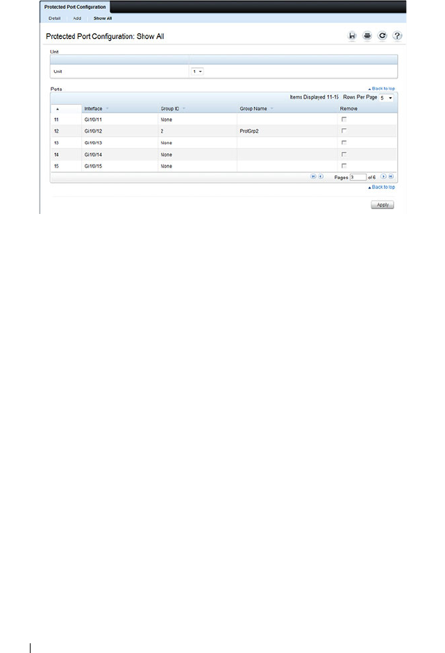
796 Configuring Port-Based Traffic Control
Figure 24-7. View Protected Port Information
11
To remove a port from a protected port group, select the
Remove
check
box associated with the port and click
Apply
.
LLPF Configuration
Use the LLPF Interface Configuration page to filter out various proprietary
protocol data units (PDUs) and/or ISDP if problems occur with these
protocols running on standards-based switches.
To display the LLPF Interface Configuration page, click Switching
→
Network Security
→
Proprietary Protocol Filtering
→
LLPF Interface
Configuration the navigation menu.
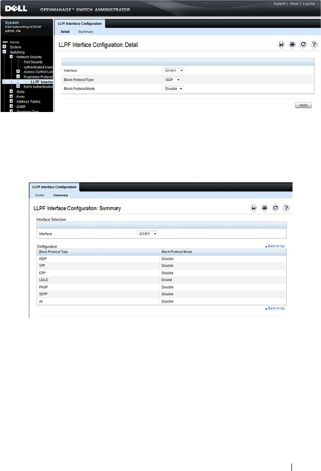
Configuring Port-Based Traffic Control 797
Figure 24-8. LLPF Interface Configuration
To view the protocol types that have been blocked for an interface, click Show
All.
Figure 24-9. LLPF Filtering Summary

798 Configuring Port-Based Traffic Control
Configuring Port-Based Traffic Control (CLI)
This section provides information about the commands you use to configure
port-based traffic control settings. For more information about the
commands, see the
Dell Networking N2000, N3000, and N4000 Series
Switches CLI Reference Guide
at support.dell.com/manuals.
Configuring Flow Control and Storm Control
Beginning in Privileged EXEC mode, use the following commands to
configure the flow control and storm control features.
Command Purpose
configure Enter global configuration mode.
flowcontrol Globally enable flow control.
interface
interface
Enter interface configuration mode for the specified
interface. The
interface
variable includes the interface type
and number, for example tengigabitethernet 1/0/3.
You can also specify a range of interfaces with the interface
range command, for example, interface range
tengigabitethernet 1/0/8-12 configures interfaces 8, 9, 10,
11, and 12.
storm-control broadcast
[level
rate
]
Enable broadcast storm recovery mode on the interface
and (optionally) set the threshold.
rate
— threshold as percentage of port speed. The
percentage is converted to a PacketsPerSecond value based
on a 512 byte average packet size.
storm-control multicast
[level
rate
]
Enable multicast storm recovery mode on the interface
and (optionally) set the threshold.
rate
— threshold as percentage of port speed. The
percentage is converted to a PacketsPerSecond value based
on a 512 byte average packet size.
storm-control unicast
[level
rate
]
Enable unknown unicast storm recovery mode on the
interface and (optionally) set the threshold.
rate
— threshold as percentage of port speed. The
percentage is converted to a PacketsPerSecond value based
on a 512 byte average packet size.

Configuring Port-Based Traffic Control 799
Configuring Protected Ports
Beginning in Privileged EXEC mode, use the following commands to add a
name to a protected port group and add ports to the group.
CTRL + Z Exit to Privileged EXEC mode.
show interfaces detail
interface
Display detailed information about the specified interface,
including the flow control status.
show storm-control View whether 802.3x flow control is enabled on the switch.
show storm-control
[
interface
| all]
View storm control settings for all interfaces or the
specified interface.
Command Purpose
configure Enter global configuration mode.
switchport protected
groupid
name
name
Specify a name for one of the three protected port groups.
•
groupid
— Identifies which group the port is to be
protected in. (Range: 0-2)
•
name
— Name of the group. (Range: 0-32 characters)
interface
interface
Enter interface configuration mode for the specified
interface. The
interface
variable includes the interface type
and number, for example tengigabitethernet 1/0/3.
switchport protected
groupid
Add the interface to the specified protected port group.
CTRL + Z Exit to Privileged EXEC mode.
show switchport
protected
View protected group and port information.
Command Purpose

800 Configuring Port-Based Traffic Control
Configuring LLPF
Beginning in Privileged EXEC mode, use the following commands to
configure LLPF settings.
Command Purpose
configure Enter global configuration mode.
interface
interface
Enter interface configuration mode for the specified
interface. The
interface
variable includes the interface type
and number, for example tengigabitethernet 1/0/3.
You can also specify a range of interfaces with the interface
range command, for example, interface range
tengigabitethernet 1/0/8-12 configures interfaces 8, 9, 10,
11, and 12.
service-acl input
{blockcdp | blockvtp |
blockdtp | blockudld |
blockpagp | blocksstp |
blockall}
Use the appropriate keyword, or combination of keywords
to block any (or all) of the following PDUs on the
interface:
•VTP
•DTP
•UDLD
•PAgP
• SSTP
•All
CTRL + Z Exit to Privileged EXEC mode.
show service-acl
interface {
interface
|
all}
View information about the blocked PDUs on the
specified interface or all interfaces.

Configuring Port-Based Traffic Control 801
Port-Based Traffic Control Configuration Example
The commands in this example configure storm control, LLPF, and protected
port settings for various interfaces on the switch.
The storm control configuration in this example sets thresholds on the switch
so that if broadcast traffic occupies more than 10% on the bandwidth on any
physical port, the interface blocks the broadcast traffic until the measured
amount of this traffic drops below the threshold.
The LLPF configuration in this example disables all PAgP and VTP PDUs
from being forwarded on any switch port or LAG.
The protected port configuration in this example prevents the clients
connected to ports 3, 4, and 9 from being able to communicate with each
other.
To configure the switch:
1
Configure storm control for broadcast traffic on all physical interfaces.
console(config)#interface range te1/0/1-24
console(config-if)#storm-control broadcast
level 10
2
Configure LLPF to block PAgP and VTP PDUs on all physical interfaces.
console(config-if)#service-acl blockpagp blockvtp
console(config-if)#exit
3
Specify a name for protected port group 0.
console(config)#protected 0 name clients
4
Add the ports to the protected port group.
console(config)#interface te1/0/3
console(config-if-Te1/0/3)#switchport protected 0
console(config-if-Te1/0/3)#exit
console(config)#interface te1/0/4
console(config-if-Te1/0/4)#switchport protected 0
console(config-if-Te1/0/4)#exit
console(config)#interface te1/0/9
console(config-if-Te1/0/9)#switchport protected 0
console(config-if-Te1/0/9)#exit
console(config)#exit

802 Configuring Port-Based Traffic Control
5
Verify the configuration.
console#show storm-control te1/0/1
Bcast Bcast Mcast Mcast Ucast Ucast
Intf Mode Level Mode Level Mode Level
------ ------- ------- ------- ------- ------- -------
Te1/0/1 Enable 10 Enable 5 Disable 5
console#show service-acl interface te1/0/1
Protocol Mode
--------------- ----------
CDP Disabled
VTP Enabled
DTP Disabled
UDLD Disabled
PAGP Enabled
SSTP Disabled
ALL Disabled
console#show switchport protected 0
Name......................................... "clients"
Member Ports: Te1/0/1, Te1/0/2, Te1/0/3, Te1/0/4, Te1/0/9

Configuring L2 Multicast Features 803
25
Configuring L2 Multicast Features
This chapter describes the layer 2 multicast features on the Dell Networking
series switches. The features this chapter describes include bridge multicast
flooding and forwarding, Internet Group Management Protocol (IGMP)
snooping, Multicast Listener Discovery (MLD) snooping, and Multicast
VLAN Registration (MVR).
The topics covered in this chapter include:
• L2 Multicast Overview
• Snooping Switch Restrictions
• Default L2 Multicast Values
• Configuring L2 Multicast Features (Web)
• Configuring L2 Multicast Features (CLI)
• Case Study on a Real-World Network Topology
L2 Multicast Overview
Multicast traffic is traffic from one source that has multiple destinations. The
L2 multicast features on the switch help control network flooding of Ethernet
multicast and IP multicast traffic by keeping track of multicast group
membership. It is essential that a multicast router be connected to a Dell
Networking layer 2 multicast switch for IGMP/MLD snooping to operate
properly. The presence of a multicast router allows the snooping switch to
relay IGMP reports to the router and to forward multicast data sources to the
multicast router as well as restrict flooding of multicast sources in a VLAN.
Multicast Flooding and Forwarding
Flooding behavior is to send incoming multicast packets to all ports in the
VLAN other than the ingress port. Forwarding behavior is to send incoming
multicast packets to selected ports in the VLAN. Forwarding behavior is

804 Configuring L2 Multicast Features
desirable as it reduces the network load by sending packets only to other
hosts/switches/routers that have indicated an interest in receiving the
multicast.
If L2 snooping is not enabled, multicast packets are flooded in the ingress
VLAN.
What Are the Multicast Bridging Features?
The Dell Networking series switches support multicast forwarding and
multicast flooding. For multicast traffic, the switch uses a database called the
Layer 2 Multicast Forwarding Database (MFDB) to make forwarding
decisions for packets that arrive with a multicast destination MAC address. By
limiting multicasts to only certain ports in the switch, traffic is prevented
from going to parts of the network where that traffic is unnecessary.
When a packet enters the switch, the destination MAC address is combined
with the VLAN ID, and a search is performed in the Layer 2 MFDB. If no
match is found, then the packet is flooded. If a match is found, then the
packet is forwarded only to the ports that are members of that multicast
group within the VLAN.
Multicast traffic destined to well-known (reserved) multicast IP addresses
(control plane traffic) is always flooded to all ports in the VLAN. The well-
known IP multicast addresses are 224.0.0.x for IPv4 and FF0x:: for IPv6.
Multicast data traffic is flooded to all ports in the VLAN if no multicast
router ports have been identified. Once a multicast router port is identified,
multicast data traffic is forwarded to the multicast router ports. The MFDB is
populated by snooping the membership reports sent to the multicast routers.
This causes multicast data traffic to be forwarded to any hosts joining the
multicast group.
What Is L2 Multicast Traffic?
L3 IP multicast traffic is traffic that is destined to a host group. Host groups
are identified by class D IPv4 addresses, which range from 224.0.1.0 to
239.255.255.255, or by FF0x:: or FF3x:: IPv6 addresses. In contrast to L3
multicast traffic, L2 multicast traffic is identified by the MAC address, i.e.,
the range 01:00:5e:00:00:00 to 01:00:5e:7f:ff:ff:ff for IPv4 multicast traffic or
33:33:xx:xx:xx:xx for IPv6 multicast traffic.

Configuring L2 Multicast Features 805
When a packet with a broadcast or multicast destination MAC address is
received, the switch will flood a copy into each of the remaining network
segments in accordance with the IEEE MAC Bridge standard. Eventually, the
packet is made accessible to all nodes connected to the network.
This approach works well for broadcast packets that are intended to be seen or
processed by all connected nodes. In the case of multicast packets, however,
this approach could lead to less efficient use of network bandwidth,
particularly when the packet is intended for only a small number of nodes.
Packets will be flooded into network segments where no node has any interest
in receiving the packet.
What Is IGMP Snooping?
IGMP snooping allows the switch to snoop on IGMP exchanges between
hosts and multicast routers and perform multicast forwarding within a VLAN.
The IGMP snooping feature complies with RFC 4541. When a switch “sees”
an IGMP report from a host for a given multicast address, the switch adds the
host's interface/VLAN to the L2 multicast group forwarding table and floods
the report to all ports in the VLAN. When the switch sees a leave message for
the group, it removes the host interface/VLAN from the L2 multicast group
forwarding table.
IGMP snooping learns about multicast routers by listening for the following
messages:
• An IGMP query packet.
• PIMv1 (IGMP type 0x14) packets with destination IP address 224.0.0.13.
• DVMRP (IGMP type 0x13) packets with destination IP address 224.0.0.4.
• PIMv2 (IP protocol type 0x67) packets with destination IP address
224.0.0.13.
Group addresses that fall into the range 224.0.0.x are never pruned by IGMP
snooping—they are always flooded to all ports in the VLAN. Note that this
flooding is based on the IP address, not the corresponding 01-00-5e-00-00-xx
MAC address.
When a multicast router is discovered, its interface is added to the interface
distribution list for all multicast groups in the VLAN. If a switch is connected
to a multicast source and no client, the switch filters the traffic from that
group to all interfaces in the VLAN. If the switch sees an IGMP join from a
host in the same VLAN, then it forwards the traffic to the host. Likewise, if

806 Configuring L2 Multicast Features
the switch sees a multicast router in the VLAN, it forwards the group to the
multicast router and does not flood in the VLAN. There is a user option to
cause the switch to flood multicast sources in the VLAN if no multicast
clients are present.
By default, dynamically discovered multicast routers are aged out every five
minutes. The user can control whether or not multicast routers age out. If all
multicast routers age out, the switch floods the VLAN with any received
multicast groups.
Multicast routers send an IGMP query every 60 seconds. This query is
intercepted by the switch and forwarded to all ports in the VLAN. All hosts
that are members of the group answer that query. The switch intercepts the
replies and forwards only one report per group from all of the received
responses.
In summary:
• IGMP snooping controls the flooding/forwarding behavior for multicast
groups. Multicast data is flooded in the VLAN until a multicast router port
is identified.
• IGMP snooping is enabled by default
• IGMP snooping forwards multicast sources to multicast routers by default
• Reserved multicast IP addresses (224.0.0.x) are always flooded to all ports
in the VLAN
• Unregistered multicast traffic may be flooded in the VLAN by a user
configuration option.
NOTE: It is strongly recommended that operators enable MLD snooping if IGMP
snooping is enabled and vice-versa. This is because both IGMP snooping and
MLD snooping utilize the same forwarding table and not enabling both may
cause unwanted pruning of protocol packets utilized by other protocols, e.g.
OSPFv3.
NOTE: IGMP snooping (and IGMP querier) validates IGMP packets. As part of
the validation, IGMP checks for the router alert option. If other devices in the
network do not send IGMP packets with the router alert option, IGMP snooping
(and snoooping querier) will discard the packet. Use the no ip igmp snooping
router-alert-check command to disable checking for the router alert option.

Configuring L2 Multicast Features 807
IGMP Snooping Querier
When PIM and IGMP are enabled in a network with IP multicast routing, the
IP multicast router acts as the IGMP querier. However, if the IP-multicast
traffic in a VLAN needs to be Layer 2 switched only, an IP-multicast router is
not required. The IGMP snooping querier can perform the role of generating
IGMP queries that would normally be performed by the multicast router.
When IGMP snooping querier is enabled, the querier switch sends out
periodic IGMP queries that trigger IGMP report messages from the hosts that
want to receive IP multicast traffic. The IGMP snooping feature listens to
these IGMP reports to identify multicast router ports. If there is another
querier in the network and the local querier is in election mode, then the
querier with the lower IP address is elected and the other querier stops
querying. If the local querier is not in election mode and another querier is
detected, the local querier stops querying.
What Is MLD Snooping?
In IPv4, Layer 2 switches use IGMP snooping to limit the flooding of
multicast traffic by dynamically configuring the multicast forwarding
database so that multicast data traffic is forwarded to only those ports
associated with a multicast router or host that has indicated an interest in
receiving a particular multicast group. In IPv6, MLD snooping performs a
similar function.
With MLD snooping, IPv6 multicast data is selectively forwarded to a list of
ports that want to receive the data instead of being flooded to all ports in a
VLAN. This list is constructed in the MFDB by snooping IPv6 multicast
control packets. MLD snooping floods multicast data packets until a
multicast router port has been identified. MLD snooping forwards
unregistered multicast data packets to IPv6 multicast routers. MLD snooping
discovers multicast routers by listening for MLD queries and populates the
MFDB.
MLD Snooping learns of multicast routers by listening for the following
packets:
• MLD query packets
NOTE: Without an IP-multicast router on a VLAN, you must configure another
switch as the IGMP querier so that it can send queries.

808 Configuring L2 Multicast Features
• PIMv2 hello packets with destination IP address as FF02::D
Dynamically learned multicast routers are timed out after an adminstrator-
configurable period of time.
MLD is a protocol used by IPv6 multicast routers to discover the presence of
multicast listeners (nodes wishing to receive IPv6 multicast packets) on its
directly-attached links and to discover which multicast packets are of interest
to neighboring nodes. MLD is derived from IGMP; MLD version 1 (MLDv1)
is equivalent to IGMPv2, and MLD version 2 (MLDv2) is equivalent to
IGMPv3. MLD is a subprotocol of Internet Control Message Protocol version
6 (ICMPv6), and MLD messages are a subset of ICMPv6 messages.
The switch snoops both MLDv1 and MLDv2 protocol packets and forwards
IPv6 multicast data based on destination IPv6 multicast MAC addresses
(33:33::). The switch floods multicast control plane traffic addressed to the
permanently assigned (well-known) multicast address FF0x::/8 to all ports in
the VLAN, except for MLD packets, which are handled according the MLD
snooping rules.
What Is Multicast VLAN Registration?
IGMP snooping helps limit multicast traffic when member ports are in the
same VLAN; however, when ports belong to different VLANs, a copy of the
multicast stream is sent to each VLAN that has member ports in the
multicast group. MVR eliminates the need to duplicate the multicast traffic
when multicast group member ports belong to different VLANs.
MVR uses a dedicated multicast VLAN to forward multicast traffic over the
L2 network. Only one MVLAN can be configured per switch, and it is used
only for certain multicast traffic, such as traffic from an IPTV application, to
avoid duplication of multicast streams for clients in different VLANs. Clients
can dynamically join or leave the mutlicast VLAN without interfering with
their membership in other VLANs.
MVR, like IGMP snooping, allows a layer 2 switch to listen to IGMP messages
to learn about multicast group membership.
NOTE: It is strongly recommended that users enable IGMP snooping if MLD
snooping is enabled and vice-versa. This is because both IGMP snooping and
MLD snooping utilize the same forwarding table, and not enabling both may
cause unwanted pruning of protocol packets utilized by other protocols, e.g.
OSPFv2.

Configuring L2 Multicast Features 809
There are two types of MVR ports: source and receiver.
• Source port is the port where multicast traffic is flowing to. It has to be the
member of so called multicast VLAN.
• Receiver port is the port where listening host is connected to the switch. It
can be the member of any VLAN, except multicast VLAN.
There are two configured learning modes of the MVR operation: dynamic and
compatible.
• In the dynamic mode MVR learns existent multicast groups by parsing the
IGMP queries from router on source ports and forwarding the IGMP joins
from the hosts to the router.
• In the compatible mode MVR does not learn multicast groups, but they
have to be configured by administrator and protocol does not forward joins
from the hosts to the router. To work in this mode the IGMP router has to
be configured to transmit required multicast streams to the network with
the MVR switch.
Enabling MVR and IGMP on the Same Interface
MVR and IGMP snooping operate independently and can both be enabled on
an interface. When both MVR and IGMP snooping are enabled, MVR listens
to the IGMP join and report messages for static multicast group information,
and IGMP snooping manages dynamic multicast groups.
When Are L3 Multicast Features Required?
In addition to L2 multicast features, the switch suports IPv4 and IPv6
multicast features. You configure the IPv4/IPv6 multicast features if the
switch functions as a multicast router that can route multicast traffic between
VLAN routing interfaces. In this case, you must enable a multicast routing
protocol on the switch, such as PIM-SM. For information about L3 multicast
features, see "Managing IPv4 and IPv6 Multicast" on page 1337.
If the switch functions as a multicast router, it is possible to enable IGMP so
that IGMP forwards multicast traffic for directly connected hosts between
VLANs. It is recommended that IGMP snooping and MLD snooping be
disabled in L3 multicast routed networks.

810 Configuring L2 Multicast Features
For information about configuring Dell Networking N2000, N3000, and
N4000 series switches as a multicast router that also performs IGMP
snooping, see "Configuring Multicast VLAN Routing With IGMP and PIM-
SM" on page 1417.
What Are GARP and GMRP?
Generic Attribute Registration Protocol (GARP) is a general-purpose protocol
that registers any network connectivity or membership-style information.
GARP defines a set of switches interested in a given network attribute, such
as VLAN ID or multicast address.
Dell Networking series switches can use GARP functionality for two
applications:
• GARP VLAN Registration Protocol (GVRP) to help dynamically manage
VLAN memberships on trunk ports.
• GARP Multicast Registration Protocol (GMRP) to help control the
flooding of multicast traffic by keeping track of group membership
information.
GVRP and GMRP use the same set of GARP Timers to specify the amount of
time to wait before transmitting various GARP messages.
NOTE: If a multicast source is connected to a VLAN on which both L3 multicast
and IGMP snooping are enabled, the multicast source is forwarded to the
mrouter ports that have been discovered when the multicast source is first seen.
If a new mrouter is later discovered on a different port, the multicast source data
is not forwarded to the new port. Likewise, if an existing mrouter times out or
stops querying, the multicast source data continues to be forwarded to the
original mrouter port. If a host in the VLAN subsequently joins or leaves the
group, the list of mrouter ports is not updated for the multicast source and the
forwarding of the multicast source is not adjusted. The workaround to this
limitation is to disable IGMP/MLD snooping and avoid the use of multi-access
VLANs in L3 multicast routed topologies.
NOTE: If MVR is enabled, IP Multicast should be disabled. Multicast routing and
MVR cannot coexist on a switch.

Configuring L2 Multicast Features 811
GMRP is similar to IGMP snooping in its purpose, but IGMP snooping is
more widely used. GMRP must be running on both the host and the switch to
function properly and IGMP/MLD snooping must be disabled on the switch,
as IGMP snooping and GMRP cannot simultaneously operate within the
same VLAN.

812 Configuring L2 Multicast Features
Snooping Switch Restrictions
Partial IGMPv3 and MLDv2 Support
The IGMPv3 and MLDv2 protocols allow multicast listeners to specify the
list of hosts from which they want to receive the traffic. However the Dell
Networking snooping switch does not track this information.
IGMPv3/MLDv2 Report messages that have the group record type
CHANGE_TO_INCLUDE_MODE with a null source list are treated as
Leave messages. All other report messages are treated as IGMPv2/MLDv1
Report messages.
MAC Address-Based Multicast Group
The L2 multicast forwarding table consists of the Multicast group MAC
address filtering entries. For IPv4 multicast groups, 16 IP multicast group
addresses map to the same multicast MAC address. For example, 224.1.1.1
and 225.1.1.1 map to the MAC address 01:00:5E:01:01:01, and IP addresses in
the range [224-239].3.3.3 map to 01:00:5E:03:03:03. As a result, if a host
requests 225.1.1.1, then it might receive multicast traffic of group 226.1.1.1 as
well.
IGMP/MLD Snooping in a Multicast Router
IGMP/MLD snooping is a Layer 2 feature and is achieved by using the L2
multicast forwarding table. If a multicast source is connected to a VLAN on
which both L3 multicast and IGMP/MLD snooping are enabled, the
multicast source is forwarded to the mrouter ports that have been discovered
when the multicast source is first seen. If a new mrouter is later discovered on
a different port, the multicast source data is not forwarded to the new port.
Likewise, if an existing mrouter times out or stops querying, the multicast
source data continues to be forwarded to the original mrouter port. If a host
in the VLAN subsequently joins or leaves the group, the list of mrouter ports
is not updated for the multicast source, and the forwarding of the multicast
source is not adjusted. The workaround to this limitation is to disable
IGMP/MLD snooping and avoid the use of multi-access VLANs in L3
multicast routing topologies.

Configuring L2 Multicast Features 813
Topologies Where the Multicast Source Is Not Directly Connected to the
Querier
If the multicast source is not directly connected to a multicast querier, the
multicast stream is forwarded to any router ports on the switch (within the
VLAN). Because multicast router queries are flooded to all ports in the
VLAN, intermediate IGMP snooping switches will receive the multicast
stream from the multicast source and forward it to the multicast router.
Using Static Multicast MAC Configuration
If configuring static multicast MAC group addresses on a port in a VLAN, it is
necessary to configure all ports in the VLAN over which it is desired that the
group traffic flow (both host and router) on all switches. IGMP snooping does
not dynamically add ports to a VLAN for a multicast group when a static
entry is configured for that group in the VLAN. This restriction applies to
both multicast router-connected ports and host-connected ports.
IGMP Snooping and GMRP
IGMP snooping and GMRP are not compatible. Only one of IGMP snooping
or GMRP should be configured to filter multicast groups for any VLAN.
Simultaneous operation of GMRP and IMGP snooping is not supported and
will lead to undesirable results, such as flooding in the VLAN due to the
inability to identify multicast router ports.

814 Configuring L2 Multicast Features
Default L2 Multicast Values
Details about the L2 multicast are in Table 25-1.
Table 25-1. L2 Multicast Defaults
Parameter Default Value
IGMP Snooping mode Enabled
MLD Snooping mode Enabled
Bridge multicast group None configured
IGMP/MLD snooping Enabled on all VLANs
IGMP/MLD snooping auto-learn Disabled
IGMP/MLD snooping host timeout 260 seconds
IGMP/MLD snooping multicast router timeout 300 seconds
IGMP/MLD snooping leave timeout 10 seconds
IGMP snooping querier Disabled
IGMP version v2
MLD version v1
IGMP/MLD snooping querier query interval 60 seconds
IGMP/MLD snooping querier expiry interval 60 seconds
IGMP/MLD snooping VLAN querier Disabled
VLAN querier election participate mode Disabled
Snooping Querier VLAN Address 0.0.0.0
MVR running Disabled
MVR multicast VLAN 1
MVR max multicast groups 256
MVR Global query response time 5 tenths of a second
MVR Mode Compatible
GARP Leave Timer 60 centiseconds
GARP Leave All Timer 1000 centiseconds
GARP Join Timer 20 centiseconds

Configuring L2 Multicast Features 815
GMRP Disabled globally and per-interface
Table 25-1. L2 Multicast Defaults (Continued)
Parameter Default Value
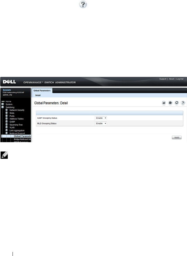
816 Configuring L2 Multicast Features
Configuring L2 Multicast Features (Web)
This section provides information about the OpenManage Switch
Administrator pages for configuring and monitoring L2 multicast features on
a Dell Networking N2000, N3000, and N4000 series switches. For details
about the fields on a page, click at the top of the page.
Multicast Global Parameters
Use the Multicast Global Parameters page to enable or disable IGMP
snooping, or MLD snooping on the switch.
To display the Multicast Global Parameters page, click Switching
→
Multicast Support
→
Global Parameters in the navigation menu.
Figure 25-1. Multicast Global Parameters
NOTE: It is strongly recommended that users enable IGMP snooping if MLD
snooping is enabled and vice-versa. This is because both IGMP snooping and
MLD snooping utilize the same forwarding table, and not enabling both may
cause unwanted pruning of protocol packets utilized by other protocols, e.g.
OSPFv2.
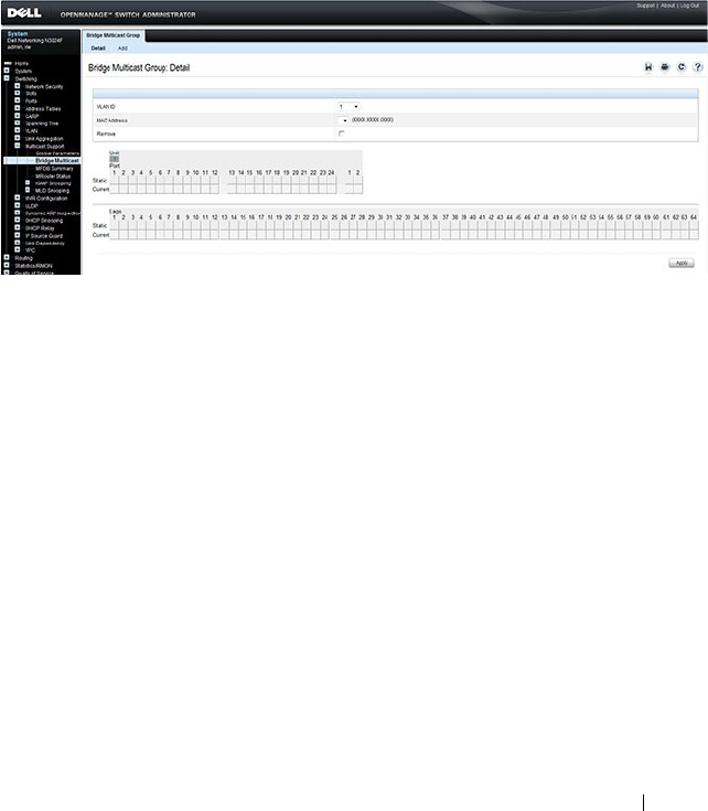
Configuring L2 Multicast Features 817
Bridge Multicast Group
Use the Bridge Multicast Group page to create new multicast service groups
or to modify ports and LAGs assigned to existing multicast service groups.
Attached interfaces display in the Port and LAG tables and reflect the manner
in which each is joined to the Multicast group.
To display the Bridge Multicast Group page, click Switching
→
Multicast
Support
→
Bridge Multicast Group in the navigation menu.
Figure 25-2. Bridge Multicast Group
Understanding the Port and LAG Member Tables
The Bridge Multicast Group tables display which Ports and LAGs are
members of the multicast group, and whether they’re static (S), dynamic (D),
or forbidden (F). The tables have two rows: Static and Current. Only the
Static row is accessible from this page. The Current row is updated when the
Static row is changed and
Apply
is clicked.
The Bridge Multicast Group page contains two editable tables:
•
Unit and Ports
— Displays and assigns multicast group membership to
ports. To assign membership, click in
Static
for a specific port. Each click
toggles between S, F, and blank. See Table 25-2 for definitions.
•
LAGs
— Displays and assigns multicast group membership to LAGs. To
assign membership, click in
Static
for a specific LAG. Each click toggles
between S, F, and blank. See Table 25-2 for definitions.

818 Configuring L2 Multicast Features
Table 25-2
contains definitions for port/LAG IGMP management settings.
Adding and Configuring Bridge Multicast Address Groups
To configure a bridge multicast group:
1
From the
Bridge Multicast Group
page, click
Add
.
The
Add Bridge Multicast Group
page displays.
Figure 25-3. Add Bridge Multicast Group
2
Select the ID of the VLAN to add to the multicast group or to modify
membership for an existing group.
3
For a new group, specify the multicast group IP or MAC address associated
with the selected VLAN.
Table 25-2. Port/LAG IGMP Management Settings
Port Control Definition
D Dynamic: Indicates that the port/LAG was dynamically joined to
the Multicast group (displays in the
Current
row).
S Static: Attaches the port to the Multicast group as a static member
in the
Static
row. Displays in the
Current
row once Apply is clicked.
F Forbidden: Indicates that the port/LAG is forbidden entry into the
Multicast group in the
Static
row. Displays in the
Current
row once
Apply is clicked.
Blank Blank: Indicates that the port is not attached to a Multicast group.

Configuring L2 Multicast Features 819
4
In the
Bridge Multicast Group
tables, assign a setting by clicking in the
Static
row for a specific port/LAG. Each click toggles between S, F, and
blank. (not a member).
5
Click
Apply
.
The bridge multicast address is assigned to the multicast group,
ports/LAGs are assigned to the group (with the
Current
rows being
updated with the
Static
settings), and the switch is updated.
Removing a Bridge Multicast Group
To delete a bridge multicast group:
1
Open the
Bridge Multicast Group
page.
2
Select the
VLAN ID
associated with the bridge multicast group to be
removed from the drop-down menu.
The
Bridge Multicast Address
and the assigned ports/LAGs display.
3
Check the
Remove
check box.
4
Click
Apply
.
The selected bridge multicast group is removed, and the device is updated.
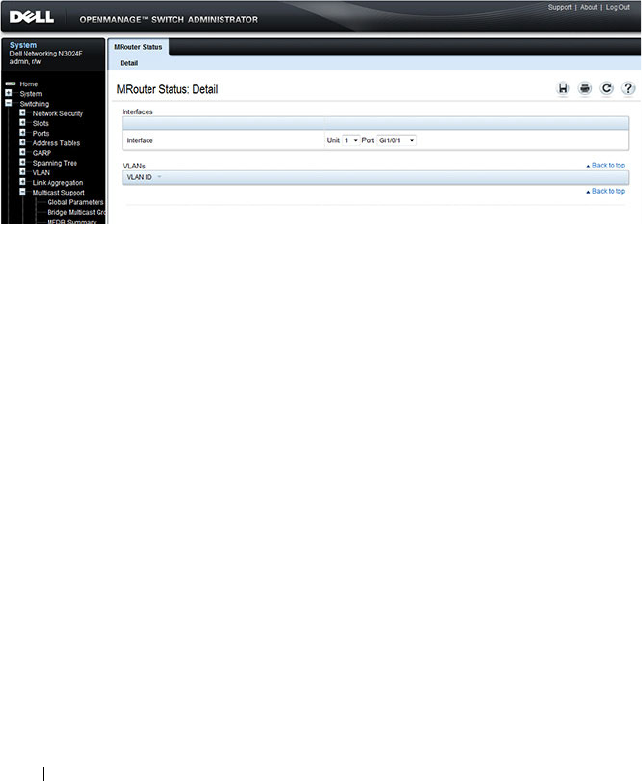
820 Configuring L2 Multicast Features
MRouter Status
Use the MRouter Status page to display the status of dynamically learned
multicast router interfaces.
To access this page, click Switching
→
Multicast Support
→
MRouter Status
in the navigation panel.
Figure 25-4. MRouter Status

Configuring L2 Multicast Features 821
General IGMP Snooping
Use the General IGMP snooping page to configure IGMP snooping settings
on specific ports and LAGs.
To display the General IGMP snooping page, click Switching
→
Multicast
Support
→
IGMP Snooping
→
General in the navigation menu.
Figure 25-5. General IGMP Snooping
Modifying IGMP Snooping Settings for Multiple Ports, LAGs, or VLANs
To modify the IGMP snooping settings:
1
From the
General
IGMP
snooping page, click
Show All
.
The
IGMP Snooping Table
displays.
2
Select the
Edit
checkbox for each Port, LAG, or VLAN to modify.
In Figure 25-6, 2 and 3 are to be modified.
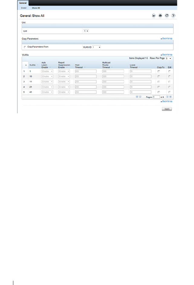
822 Configuring L2 Multicast Features
Figure 25-6. Edit IGMP Snooping Settings
3
Edit the IGMP snooping fields as needed.
4
Click
Apply
.
The IGMP snooping settings are modified, and the device is updated.
Copying IGMP Snooping Settings to Multiple Ports, LAGs, or VLANs
To copy IGMP snooping settings:
1
From the
General
IGMP
snooping
page, click
Show All
.
The
IGMP
Snooping Table
displays.
2
Select the
Copy Parameters From
checkbox.
3
Select a Unit/Port, LAG, or VLAN to use as the source of the desired
parameters.
4
Select the
Copy To
checkbox for the Unit/Ports, LAGs, or VLANs that
these parameters will be copied to.
In Figure 25-7, the settings for VLAN 21 will be copied to ports 3 and 5.

Configuring L2 Multicast Features 823
Figure 25-7. Copy IGMP Snooping Settings
5
Click
Apply
.
The IGMP snooping settings are modified, and the device is updated.
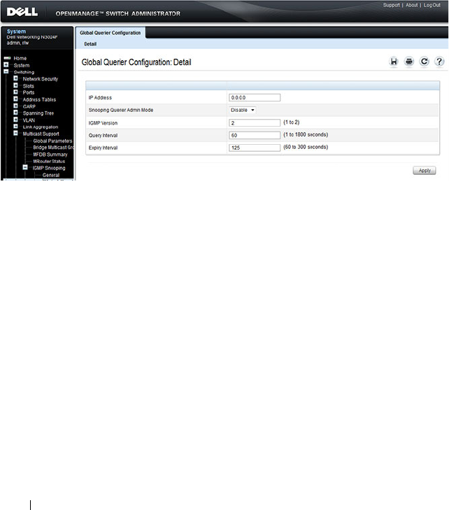
824 Configuring L2 Multicast Features
Global Querier Configuration
Use the Global Querier Configuration page to configure IGMP snooping
querier settings, such as the IP address to use as the source in periodic IGMP
queries when no source address has been configured on the VLAN.
To display the Global Querier Configuration page, click Switching
→
Multicast Support
→
IGMP Snooping
→
Global Querier Configuration in
the navigation menu.
Figure 25-8. Global Querier Configuration
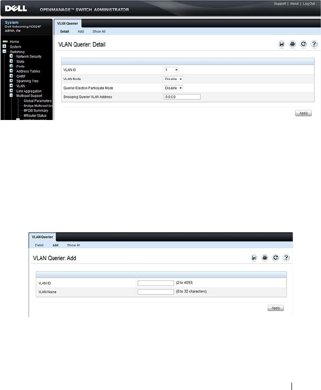
Configuring L2 Multicast Features 825
VLAN Querier
Use the VLAN Querier page to specify the IGMP snooping querier settings
for individual VLANs.
To display the VLAN Querier page, click Switching
→
Multicast Support
→
IGMP Snooping
→
VLAN Querier in the navigation menu.
Figure 25-9. VLAN Querier
Adding a New VLAN and Configuring its VLAN Querier Settings
To configure a VLAN querier:
1
From the
VLAN Querier
page, click
Add
.
The page refreshes, and the
Add VLAN
page displays.
Figure 25-10. Add VLAN Querier
2
Enter the VLAN ID and, if desired, an optional VLAN name.
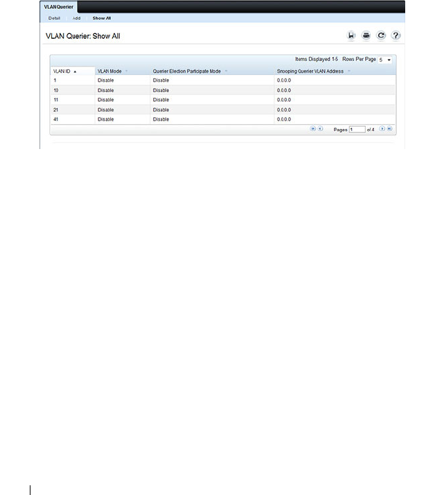
826 Configuring L2 Multicast Features
3
Return to the
VLAN Querier
page and select the new VLAN from the
VLAN ID
menu.
4
Specify the VLAN querier settings.
5
Click
Apply
.
The VLAN Querier settings are modified, and the device is updated.
To view a summary of the IGMP snooping VLAN querier settings for all
VLANs on the switch, click Show All.
Figure 25-11. Add VLAN Querier
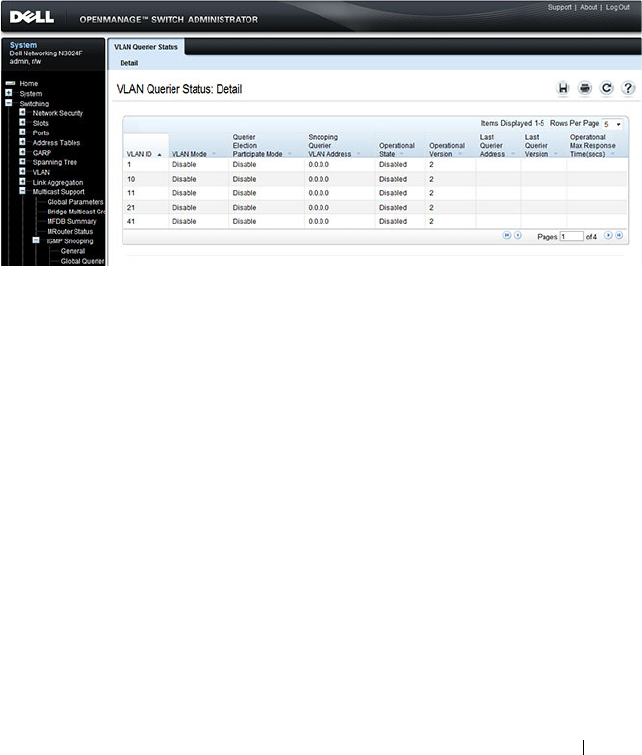
Configuring L2 Multicast Features 827
VLAN Querier Status
Use the VLAN Querier Status page to view the IGMP snooping querier
settings for individual VLANs.
To display the VLAN Querier Status page, click Switching
→
Multicast
Support
→
IGMP Snooping
→
VLAN Querier Status in the navigation
menu.
Figure 25-12. IGMP Snooping VLAN Querier Status
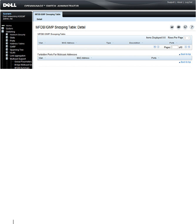
828 Configuring L2 Multicast Features
MFDB IGMP Snooping Table
Use the MFDB IGMP Snooping Table page to view the multicast forwarding
database (MFDB) IGMP Snooping Table and Forbidden Ports settings for
individual VLANs.
To display the MFDB IGMP Snooping Table page, click Switching
→
Multicast Support
→
IGMP Snooping
→
MFDB IGMP Snooping Table in
the navigation menu.
Figure 25-13. MFDB IGMP Snooping Table
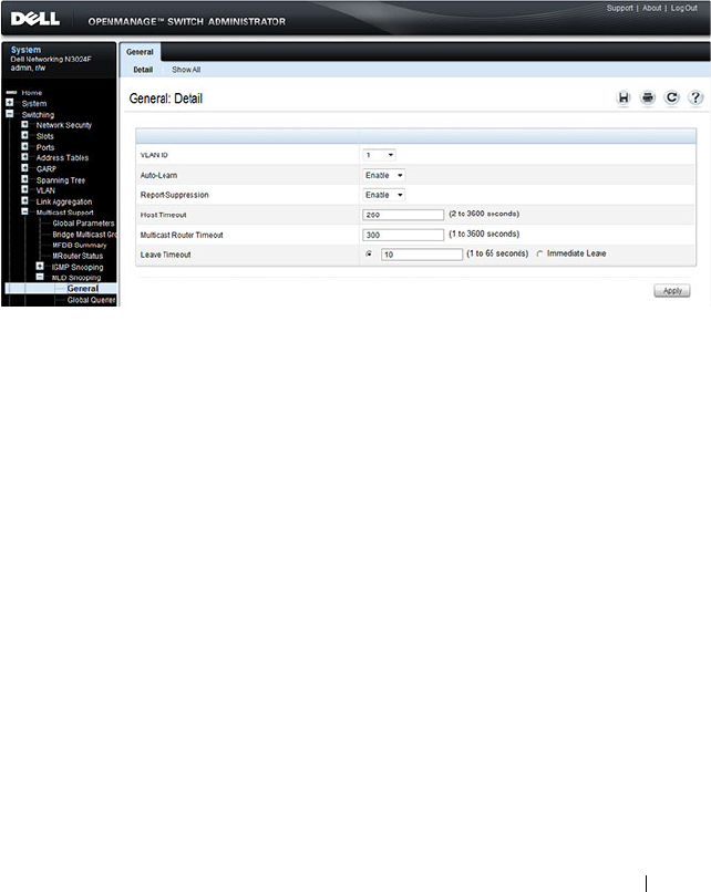
Configuring L2 Multicast Features 829
MLD Snooping General
Use the MLD Snooping General page to add MLD members.
To access this page, click Switching
→
Multicast Support
→
MLD Snooping
→
General in the navigation panel.
Figure 25-14. MLD Snooping General
Modifying MLD Snooping Settings for VLANs
To configure MLD snooping:
1
From the
General
MLD
snooping page, click
Show All
.
The
MLD Snooping Table
displays.
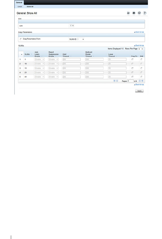
830 Configuring L2 Multicast Features
Figure 25-15. MLD Snooping Table
2
Select the
Edit
checkbox for each VLAN to modify.
3
Edit the MLD snooping fields as needed.
4
Click
Apply
.
The MLD snooping settings are modified, and the device is updated.
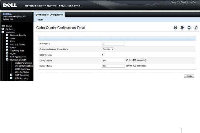
Configuring L2 Multicast Features 831
Copying MLD Snooping Settings to VLANs
To copy MLD snooping settings:
1
From the
General
MLD
snooping
page, click
Show All
.
The
MLD
Snooping Table
displays.
2
Select the
Copy Parameters From
checkbox.
3
Select a VLAN to use as the source of the desired parameters.
4
Select the
Copy To
checkbox for the VLANs that these parameters will be
copied to.
5
Click
Apply
.
The MLD snooping settings are modified, and the device is updated.
MLD Snooping Global Querier Configuration
Use the
MLD Snooping
Global Querier Configuration page to configure the
parameters for the MLD snooping querier.
To display the Global Querier Configuration page, click Switching
→
Multicast Support
→
MLD Snooping
→
Global Querier Configuration in
the navigation menu.
Figure 25-16. MLD Snooping Global Querier Configuration
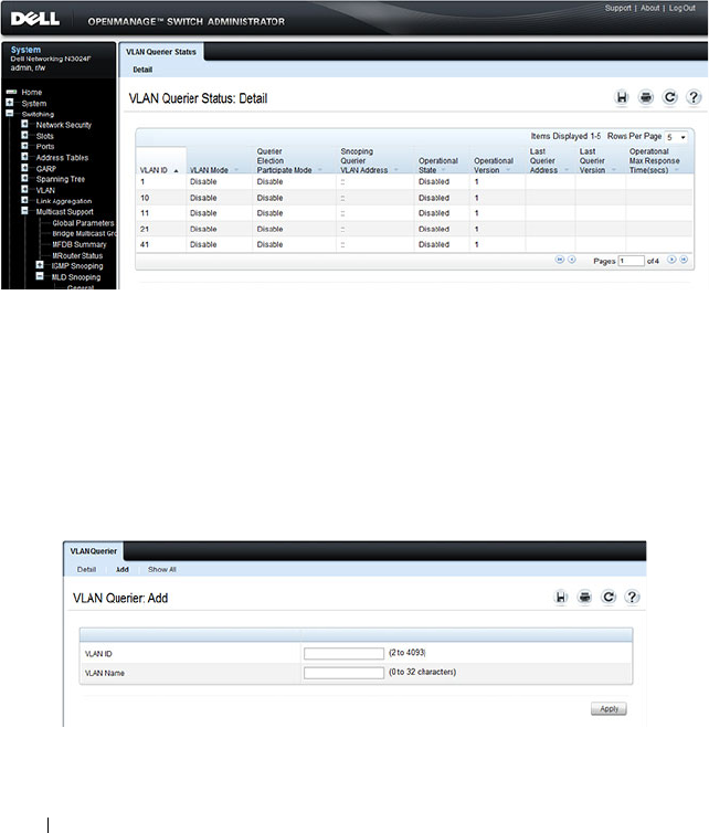
832 Configuring L2 Multicast Features
MLD Snooping VLAN Querier
Use the
MLD Snooping
VLAN Querier page to specify the MLD snooping
querier settings for individual VLANs.
To display the
MLD Snooping
VLAN Querier page, click Switching
→
Multicast Support
→
MLD Snooping
→
VLAN Querier in the navigation
menu.
Figure 25-17. MLD Snooping VLAN Querier
Adding a New VLAN and Configuring its MLD Snooping VLAN Querier Settings
To configure an MLD snooping VLAN querier:
1
From the
VLAN Querier
page, click
Add
.
The page refreshes, and the
Add VLAN
page displays.
Figure 25-18. Add MLD Snooping VLAN Querier
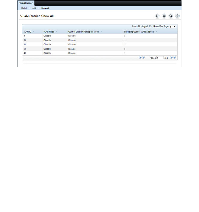
Configuring L2 Multicast Features 833
2
Enter the VLAN ID and, if desired, an optional VLAN name.
3
Return to the
VLAN Querier
page and select the new VLAN from the
VLAN ID
menu.
4
Specify the VLAN querier settings.
5
Click
Apply
.
The VLAN Querier settings are modified, and the device is updated.
To view a summary of the IGMP snooping VLAN querier settings for all
VLANs on the switch, click Show All.
Figure 25-19. Add VLAN Querier
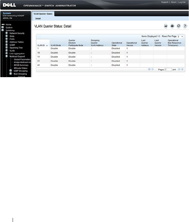
834 Configuring L2 Multicast Features
MLD Snooping VLAN Querier Status
Use the VLAN Querier Status page to view the MLD snooping querier
settings for individual VLANs.
To display the VLAN Querier Status page, click Switching
→
Multicast
Support
→
MLD Snooping
→
VLAN Querier Status in the navigation
menu.
Figure 25-20. MLD Snooping VLAN Querier Status
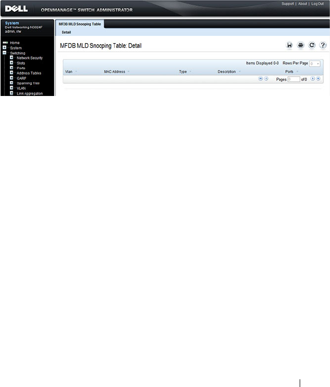
Configuring L2 Multicast Features 835
MFDB MLD Snooping Table
Use the MFDB MLD Snooping Table page to view the MFDB MLD
snooping table settings for individual VLANs.
To display the MFDB MLD Snooping Table page, click Switching
→
Multicast Support
→
MLD Snooping
→
MFDB MLD Snooping Table in
the navigation menu.
Figure 25-21. MFDB MLD Snooping Table
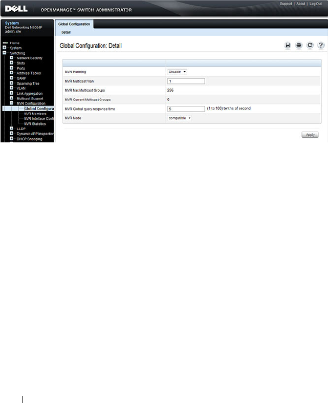
836 Configuring L2 Multicast Features
MVR Global Configuration
Use the MVR Global Configuration page to enable the MVR feature and
configure global parameters. To display the MVR Global Configuration
page, click Switching
→
MVR Configuration
→
Global Configuration in
the navigation panel.
Figure 25-22. MVR Global Configuration
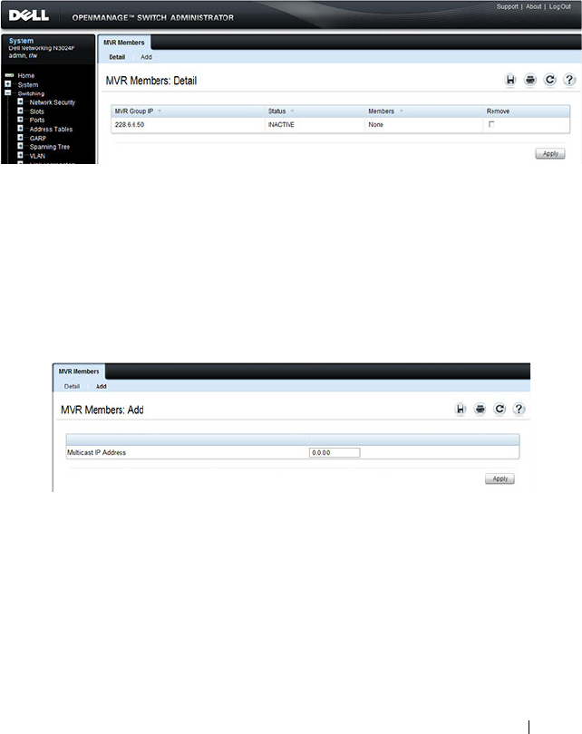
Configuring L2 Multicast Features 837
MVR Members
Use the MVR Members page to view and configure MVR group members. To
display the MVR Members page, click Switching
→
MVR Configuration
→
MVR Members in the navigation panel.
Figure 25-23. MVR Members
Adding an MVR Membership Group
To add an MVR membership group:
1
From the
MVR Membership
page, click
Add
.
The MVR
Add Group
page displays.
Figure 25-24. MVR Member Group
2
Specify the MVR group IP multicast address.
3
Click
Apply
.
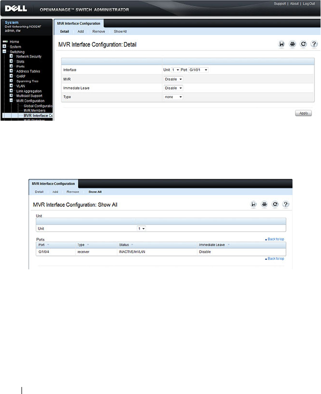
838 Configuring L2 Multicast Features
MVR Interface Configuration
Use the MVR Interface Configuration page to enable MVR on a port,
configure its MVR settings, and add the port to an MVR group. To display the
MVR Interface Configuration page, click Switching
→
MVR Configuration
→
MVR Interface Configuration in the navigation panel.
Figure 25-25. MVR Interface Configuration
To view a summary of the MVR interface configuration, click Show All.
Figure 25-26. MVR Interface Summary
Adding an Interface to an MVR Group
To add an interface to an MVR group:
1
From the
MVR Interface
page, click
Add
.
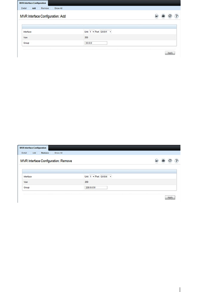
Configuring L2 Multicast Features 839
Figure 25-27. MVR - Add to Group
2
Select the interface to add to the MVR group.
3
Specify the MVR group IP multicast address.
4
Click
Apply
.
Removing an Interface from an MVR Group
To remove an interface from an MVR group:
1
From the
MVR Interface
page, click
Remove
.
Figure 25-28. MVR - Remove from Group
2
Select the interface to remove from an MVR group.
3
Specify the IP multicast address of the MVR group.
4
Click
Apply
.
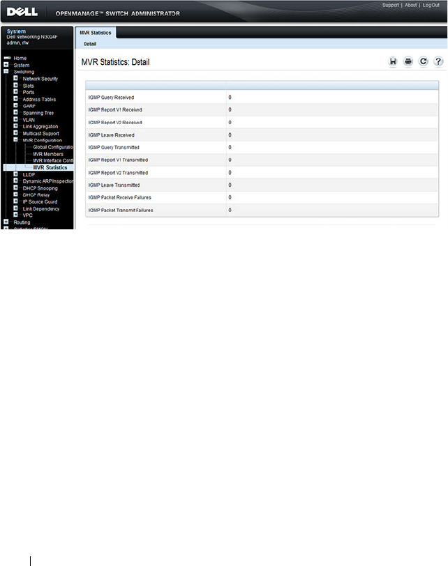
840 Configuring L2 Multicast Features
MVR Statistics
Use the MVR Statistics page to view MVR statistics on the switch. To display
the MVR Statistics page, click Switching
→
MVR Configuration
→
MVR
Statistics in the navigation panel.
Figure 25-29. MVR Statistics
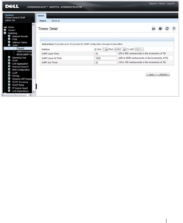
Configuring L2 Multicast Features 841
GARP Timers
The Timers page contains fields for setting the GARP timers used by GVRP
and GMRP on the switch.
To display the Timers page, click Switching
→
GARP
→
Timers in the
navigation panel.
Figure 25-30. GARP Timers
Configuring GARP Timer Settings for Multiple Ports
To configure GARP timers on multiple ports:
1
Open the
Timers
page.
2
Click
Show All
to display the
GARP Timers Table
.
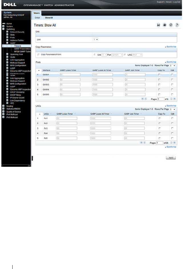
842 Configuring L2 Multicast Features
Figure 25-31. Garp Timers Table
3
For each port or LAG to configure, select the check box in the
Edit
column in the row associated with the port.
4
Specify the desired timer values.
5
Click
Apply
.
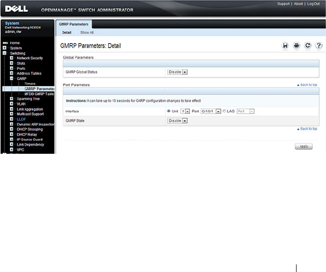
Configuring L2 Multicast Features 843
Copying GARP Timer Settings From One Port to Others
To copy GARP timer settings:
1
Select the
Copy Parameters From
check box, and select the port or LAG
with the settings to apply to other ports or LAGs.
2
In the Ports or LAGs list, select the check box(es) in the
Copy To
column
that will have the same settings as the port selected in the
Copy
Parameters From
field.
3
Click
Apply
to copy the settings.
GMRP Parameters
Use the GMRP Parameters page to configure the administrative mode of
GMRP on the switch and on each port or LAG.
To display the GMRP Parameters page, click Switching
→
GARP
→
GMRP
Parameters in the navigation panel.
Figure 25-32. GMRP Parameters
Configuring GMRP Parameters on Multiple Ports
To configure GMRP settings:
1
Open the
GMRP Parameters
page.
2
Click
Show All
to display the
GMRP Port Configuration Table
.
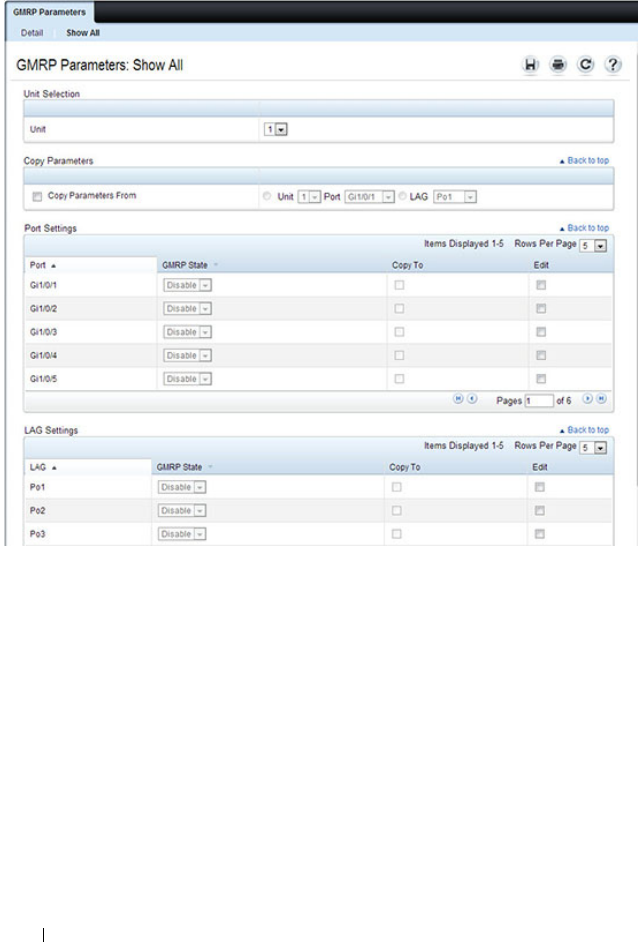
844 Configuring L2 Multicast Features
Figure 25-33. GMRP Port Configuration Table
3
For each port or LAG to configure, select the check box in the
Edit
column in the row associated with the port.
4
Specify the desired timer values.
5
Click
Apply
.
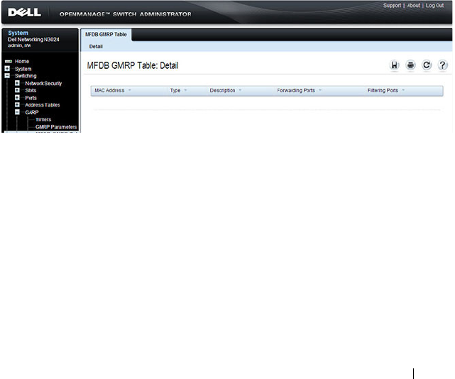
Configuring L2 Multicast Features 845
Copying Settings From One Port or LAG to Others
To copy GMRP settings:
1
Select the
Copy Parameters From
check box, and select the port or LAG
with the settings to apply to other ports or LAGs.
2
In the Ports or LAGs list, select the check box(es) in the
Copy To
column
that will have the same settings as the port selected in the
Copy
Parameters From
field.
3
Click
Apply
to copy the settings.
MFDB GMRP Table
Use the MFDB GMRP Table page to view all of the entries in the Multicast
Forwarding Database that were created for the GMRP
To display the MFDB GMRP Table page, click Switching
→
GARP
→
MFDB GMRP Table in the navigation panel.
Figure 25-34. MFDB GMRP Table

846 Configuring L2 Multicast Features
Configuring L2 Multicast Features (CLI)
This section provides information about the commands you use to configure
L2 multicast settings on the switch. For more information about the
commands, see the
Dell Networking N2000, N3000, and N4000 Series
Switches CLI Reference Guide
at support.dell.com/manuals. Because L3 IP
multicast (PIM/IGMP) utilizes a separate forwarding database from L2
multicast, it is recommended that L3 multicast features, including PIM and
IGMP, be disabled on L2 multicast enabled switches.
Configuring Layer 2 Multicasting
Beginning in Privileged EXEC mode, use the following commands to
configure MAC address table features.
Command Purpose
configure Enter global configuration mode.
mac address-table static
mac-multicast-address
vlan
vlan-id
interface
interface-id
Register a MAC-layer Multicast address in the bridge
table.
•
mac-multicast-address
— MAC multicast address in the
format xxxx.xxxx.xxxx or xx:xx:xx:xx:xx:xx.
•
interface-id
— A physical interface or port-channel.
mac address-table
multicast forbidden
address vlan
vlan-id
{
mac-multicast-address
|
ip-multicast-address
}
{add | remove}
interface
interface-list
Forbid adding a specific Multicast address to specific ports.
•
mac-multicast-address
— MAC multicast address in the
format xxxx.xxxx.xxxx.
•
ip- multicast-address
— IP multicast address.
•
add
— Adds ports to the group. If no option is specified,
this is the default option.
•
remove
— Removes ports from the group.
•
interface-list
— Specifies the interface type (
port-
channel
,
gigabitethernet
,
tengigabitethernet
) and
number. Separate nonconsecutive interfaces with a
comma and no spaces; use a hyphen to designate a range
of ports.
exit Exit to Privileged EXEC mode.

Configuring L2 Multicast Features 847
Configuring IGMP Snooping on VLANs
Beginning in Privileged EXEC mode, use the following commands to
configure IGMP snooping settings on VLANs.
show mac address-table
multicast [vlan
vlan-id
]
[address
mac-multicast-
address
|
ip-multicast-
address
] [format ip |
mac]]
View entries in the multicast MAC address table. The
show mac address-table multicast command shows only
multicast addresses. Multicast address are shown along
with unicast addresses if the multicast keyword is not used.
Command Purpose
configure Enter global configuration mode.
ip igmp snooping vlan
vlan-id
Enable IGMP snooping on the specified VLAN.
ip igmp snooping vlan
vlan-id
groupmembership-
interval
seconds
Specify the host time-out value for the specified VLAN. If
an IGMP report for a multicast group is not received in
the number of seconds specified by the
seconds
value, this
port is deleted from the VLAN member list of that
multicast group. This command also enables IGMP
snooping on the VLAN.
ip igmp snooping vlan
vlan-id
last-member-
query-interval
seconds
Specify the leave time-out value for the VLAN. If an
IGMP report for a multicast group is not received within
the number of seconds configured with this command
after an IGMP leave was received from a specific interface,
the current port is deleted from the VLAN member list of
that multicast group.
ip igmp snooping vlan
vlan-id
immediate-leave
Enables IGMP snooping immediate-leave mode on the
specified VLAN. Enabling immediate-leave allows the
switch to immediately remove the layer 2 LAN interface
from its forwarding table entry upon receiving an IGMP
leave message for that multicast group without first
sending out MAC-based general queries to the interface.
Command Purpose

848 Configuring L2 Multicast Features
Configuring IGMP Snooping Querier
Beginning in Privileged EXEC mode, use the following commands to
configure IGMP snooping querier settings on the switch and on VLANs.
ip igmp snooping vlan
vlan-id
mcrtexpiretime
seconds
Specify the multicast router time-out value for to
associate with a VLAN. This command sets the number of
seconds to wait to age out an automatically-learned
multicast router port.
CTRL + Z Exit to Privileged EXEC mode.
show ip igmp snooping
groups
Shows IGMP snooping configuration on all VLANs.
show ip igmp snooping
vlan
vlan-id
View the IGMP snooping settings on the VLAN.
Command Purpose
configure Enter global configuration mode.
ip igmp snooping querier
[vlan
vlan-id
] [address
ip-address
]
Enable the IGMP snooping querier on the switch or on
the VLAN specified with the
vlan-id
parameter.
Use the optional
ip-address
parameter to specify the IP
address that the snooping querier switch should use as the
source address when generating periodic queries.
ip igmp snooping querier
query-interval
interval-
count
Set the IGMP snooping querier query interval time, which
is the amount of time in seconds that the switch waits
before sending another periodic query. The range is
1–1800 seconds.
ip igmp snooping querier
timer expiry
seconds
Set the IGMP snooping querier timer expiration period.
This is the time period, in seconds, that the switch
remains in non-querier mode after it has discovered that
there is a multicast querier in the network.
ip igmp snooping querier
version
version
Set the IGMP version of the query that the switch sends
periodically. The
version
range is 1–2.
ip igmp snooping querier
vlan-id
Enable the IGMP snooping querier on the specified
VLAN.
Command Purpose

Configuring L2 Multicast Features 849
Configuring MLD Snooping on VLANs
Beginning in Privileged EXEC mode, use the following commands to
configure MLD snooping settings on VLANs.
ip igmp snooping querier
election participate
vlan-
id
Allow the IGMP snooping querier to participate in the
querier election process when it discovers the presence of
another querier in the VLAN. When this mode is enabled,
if the snooping querier finds that the other querier source
address is more than the snooping querier address, it stops
sending periodic queries. If the snooping querier wins the
election, then it continues sending periodic queries and
the other querier ceases sending queries. Use of election
mode is not recommended when multicast routers are
present in the network.
CTRL + Z Exit to Privileged EXEC mode.
show ip igmp snooping
querier [detail |vlan
vlan-id
]
View IGMP snooping querier settings configured on the
switch, on all VLANs, or on the specified VLAN.
Command Purpose
configure Enter global configuration mode.
ipv6 mld snooping vlan
vlan-id
Enable MLD snooping on the specified VLAN.
ipv6 mld snooping vlan
vlan-id
groupmembership-
interval
seconds
Specify the host time-out value for the specified VLAN. If
an MLD report for a multicast group is not received in the
number of seconds specified by the
seconds
value, this
VLAN is deleted from the member list of that multicast
group.
ipv6 mld snooping
vlan-
id
last-listener-query-
interval
seconds
Specify the leave time-out value for the VLAN. If an MLD
report for a multicast group is not received within the
number of seconds configured with this command after
an MLD leave was received from a specific interface, the
current port is deleted from the VLAN member list of that
multicast group.
Command Purpose

850 Configuring L2 Multicast Features
Configuring MLD Snooping Querier
Beginning in Privileged EXEC mode, use the following commands to
configure MLD snooping querier settings on the switch and on VLANs.
ipv6 mld snooping vlan
vlan-id
immediate-leave
Enables MLD snooping immediate-leave mode on the
specified VLAN. Enabling immediate-leave allows the
switch to immediately remove the layer 2 LAN interface
from its forwarding table entry upon receiving an MLD
leave message for that multicast group without first
sending out MAC-based general queries to the interface.
ipv6 mld snooping vlan
vlan-id
mcrtexpiretime
seconds
Specify the multicast router time-out value for to
associate with a VLAN. This command sets the number of
seconds to wait to age out an automatically-learned
multicast router port.
CTRL + Z Exit to Privileged EXEC mode.
show ipv6 mld snooping
vlan
vlan-id
View the MLD snooping settings on the VLAN.
Command Purpose
configure Enter global configuration mode.
ipv6 mld snooping
querier
Enable the MLD snooping querier on the switch.
ipv6 mld snooping
querier vlan
vlan-id
[address
ipv6-address
]
Enable the MLD snooping querier on VLAN specified
with the
vlan-id
parameter.
Use the optional
ip-address
parameter to specify the IP
address that the snooping querier switch should use as the
source address when generating periodic queries.
Command Purpose

Configuring L2 Multicast Features 851
Configuring MVR
Beginning in Privileged EXEC mode, use the following commands to
configure MVR features on the switch.
ipv6 mld snooping
querier election
participate
vlan-id
Allow the MLD snooping querier to participate in the
querier election process when it discovers the presence of
another querier in the VLAN. When this mode is enabled,
if the snooping querier finds that the other querier source
address is more than the snooping querier address, it stops
sending periodic queries. If the snooping querier wins the
election, then it continues sending periodic queries. Use
of election mode is not recommended when multicast
routers are present in the network.
exit Exit to Global Configuration mode.
ipv6 mld snooping
querier address
ipv6-
address
Specify the IP address that the snooping querier switch
should use as the source address when generating periodic
queries.
ipv6 mld snooping
querier query-interval
interval-count
Set the MLD snooping querier query interval time, which
is the amount of time in seconds that the switch waits
before sending another periodic query. The range is
1–1800 seconds.
ipv6 mld snooping
querier timer expiry
seconds
Set the MLD snooping querier timer expiration period.
This is the time period, in seconds, that the switch
remains in non-querier mode after it has discovered that
there is a multicast querier in the network.
exit Exit to Privileged EXEC mode.
show ipv6 mld snooping
querier [detail |vlan
vlan-id
]
View MLD snooping querier settings configured on the
switch, on all VLANs, or on the specified VLAN.
Command Purpose
configure Enter global configuration mode.
mvr Enable MVR on the switch.
mvr vlan
vlan-id
Set the VLAN to use as the multicast VLAN for MVR.
Command Purpose

852 Configuring L2 Multicast Features
mvr querytime
time
Set the MVR query response time. The value for
time
is in
units of tenths of a second.
mvr mode {compatible |
dynamic}
Specify the MVR mode of operation.
mvr group
mcast-address
[
groups
]
Add an MVR membership group.
•
mcast-address
—The group IP multicast address
•
group
—Specifies the number of contiguous groups
interface
interface
Enter interface configuration mode for the specified port.
The
interface
variable includes the interface type and
number, for example tengigabitethernet 1/0/3.
You can also specify a range of ports with the interface
range command, for example, interface range
tengigabitethernet 1/0/8-12 configures interfaces 8, 9, 10,
11, and 12.
mvr Enable MVR on the port.
mvr immediate Enable MVR immediate leave mode on the port.
mvr type {source |
receiver}
Specify the MVR port type.
mvr vlan
vlan-id
group
mcast-address
Allow the port to participate in the specified MVR group.
The
vlan-id
parameter is the ID of the MVR multicast
VLAN.
CTRL + Z Exit to Privileged EXEC mode.
show ip dhcp snooping
[interfaces]
View the DHCP snooping global and per port
configuration.
show ip dhcp snooping
binding [{static |
dynamic}] [interface
port
] [vlan
vlan-id
]
View the entries in the DHCP snooping bindings database.
show mvr View information about the administrative mode of MVR.
show mvr members View information about MVR groups and their members.
show mvr interface
interface
View information about the MVR configuration for a
specific port.
show mvr traffic View information about IGMP traffic in the MVR table.
Command Purpose

Configuring L2 Multicast Features 853
Configuring GARP Timers and GMRP
Beginning in Privileged EXEC mode, use the following commands to
configure the GARP timers and to control the administrative mode GMRP on
the switch and per-interface.
Command Purpose
configure Enter global configuration mode.
garp timer {join | leave |
leaveall}
timer_value
Adjust the GARP application join, leave, and leaveall
GARP timer values
The
timer_value
variable is in centiseconds. The range is
10-100 for join, 20-600 for leave, and 200-6000 for
leaveall.
gmrp enable Enable GMRP globally on the switch.
interface
interface
Enter interface configuration mode for the specified port
or LAG. The
interface
variable includes the interface type
and number, for example tengigabitethernet 1/0/3. For a
LAG, the interface type is port-channel.
You can also specify a range of ports with the interface
range command, for example, interface range
tengigabitethernet 1/0/8-12 configures interfaces 8, 9, 10,
11, and 12.
gmrp enable Enable GMRP on the interface or range of interfaces.
exit Exit to Global Config mode.
exit Exit to Privileged EXEC mode.
show gmrp configuration View the administrative status of GMRP on the switch
and all interfaces.
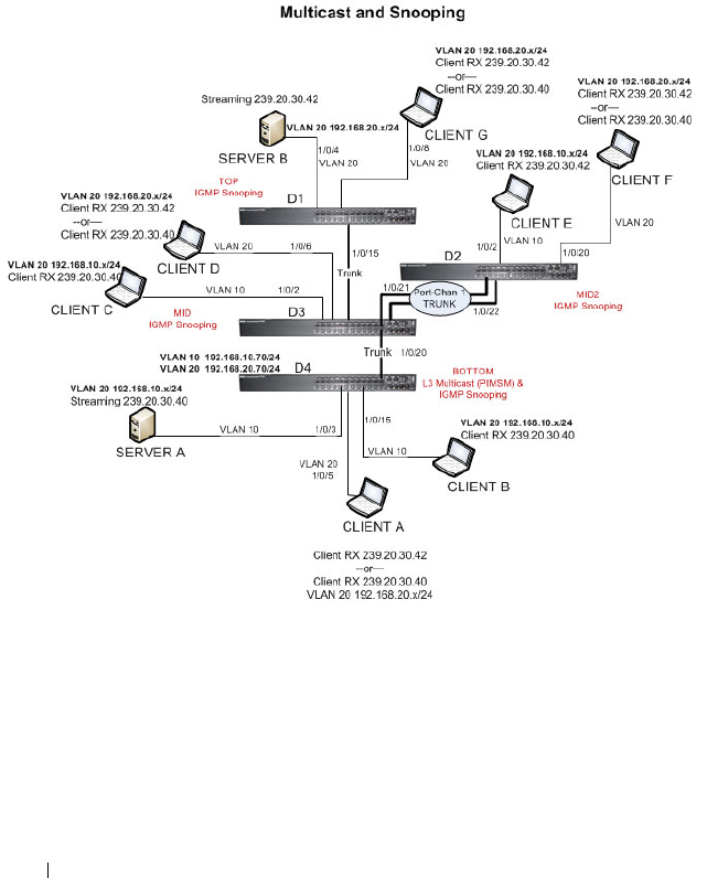
854 Configuring L2 Multicast Features
Case Study on a Real-World Network Topology
Multicast Snooping Case Study
Figure 25-35 shows the topology that the scenarios in this case study use.
Figure 25-35. Case Study Topology
The topology in Figure 25-35 includes the following elements:
• Snooping Switches: D1, D2, D3 with IGMP snooping enabled on VLANs
10, 20
• Multicast Router: D4 with PIM-SM enabled and IGMP snooping disabled
on VLANs 10, 20
• Multicast Listeners: Client A-G

Configuring L2 Multicast Features 855
• Multicast Sources: Server A – 239.20.30.40, Server B – 239.20.30.42
• Subnets: VLAN 10 – 192.168.10.x, VLAN 20 – 192.168.20.x
• Mrouter ports: D3 – 1/0/20, D2 – PortChannel1, D1 – 1/0/15
Snooping Within a Subnet
In the example network topology, the multicast source and listeners are in the
same subnet VLAN 20
–
192.168.20.x/24. D4 sends periodic queries on VLAN
10 and 20, and these queries are forwarded to D1, D2, and D3 via trunk links.
Snooping switches D1, D2, and D3 flood these queries in VLANs 10 and 20
to clients G, F, and D, respectively.
Multicast Source and Listener directly connected to a snooping switch:
Server B Client G
1
Client G sends a report for 239.20.30.42.
2
The report is forwarded to multicast router D4 via D1 – 1/0/15 and D3 –
1/0/20.
3
A forwarding entry is created by D1 for VLAN 20, 239.20.30.42 – 1/0/8,
1/0/15.
4
Client G receives the multicast stream from Server B.
5
D3 receives the multicast stream and it is forwarded to D4 because D4 is a
multicast router.
6
Client D sends a report for 239.20.30.42.
7
The report is forwarded to multicast router D4 via D3 – 1/0/20.
8
A forwarding entry is created by D3 for VLAN 20, 239.20.30.42 – 1/0/6,
1/0/20.
9
Client D receives the multicast stream from Server B.
10
Client F does not receive the multicast stream because it did not respond
to queries from D4.
Multicast Source and Listener connected by intermediate snooping switches:
Server B Client D
1
Client D sends a report for 239.20.30.42.
2
The report is forwarded to multicast router D4 via D3 – 1/0/20.

856 Configuring L2 Multicast Features
3
A forwarding entry is created by D3 for VLAN20, 239.20.30.42 – 1/0/6,
1/0/20.
4
Client D will receive the multicast stream from Server B because it is
forwarded by D1 to D3 and then to D4 because D4 is a multicast router.
Because the multicast stream is present on D3, a L2 forwarding entry is
created on D3, where 239.20.30.42 is not a registered group.
5
Client F does not receive the multicast stream because it did not respond
to queries from D4.
Snooping Switch Interaction with a Multicast Router
In the example network topology, consider Client B and Server A. Both are in
the same subnet VLAN10
–
192.168.10.70/24. Server A is a source for
multicast stream 239.20.30.40. D4 sends periodic queries on VLAN 10 and
VLAN 20, and these queries reach D1, D2, and D3 via trunk links, which in
turn forward them in VLAN 10 and VLAN 20 to reach their respective
attached clients. PIM-SM is enabled and IGMP snooping is disabled on
router D4, and IGMP snooping is enabled on D1, D2, and D3.
Multicast Source and Listener directly connected to Multicast Router on the
same routing VLAN: Server A Client B
1
Because multicast routing is enabled on D4 VLAN 10, an IP multicast
table entry is created to include D4 – 1/0/15, D4 – 1/0/20 as part of the L2
forwarding list members.
2
Client B sends a report for 239.20.30.40.
3
The IP multicast table entry is modified to include only D4 – 1/0/15 as the
layer 2 forwarding list member.
4
Client B receives multicast data.
5
The multicast stream is not forwarded to D3 on trunk link 1/0/20 because
no other clients requested this data.
Multicast Source directly connected to Multicast Router, and Listener
connected to a different routing VLAN via intermediate snooping switches:
Server A Client F
Clients A, D and F are in the same subnet VLAN20 - 192.168.20.70/24. Server
A is in a different subnet VLAN10
–
192.168.10.70/24.
1
Client F sends a report for 239.20.30.40.

Configuring L2 Multicast Features 857
2
A multicast forwarding entry is created on D2 VLAN20, 239.20.30.40 –
1/0/20, PortChannel1.
3
The Client F report message is forwarded to D3-PortChannel1 (multicast
router attached port).
4
A multicast forwarding entry is created on D3 VLAN 20, 239.20.30.40 –
PortChannel1, 1/0/20.
5
The Client F report message is forwarded to D4 via D3 – 1/0/20 (multicast
router attached port).
6
An IP multicast routing entry is created on D4 VLAN 10 – VLAN 20 with
the L3 outgoing port list as VLAN 20 – 1/0/20.
7
The multicast stream is routed to D3.
8
The multicast stream is forwarded to listener Client F using forwarding
entries created on D3 and D2.
9
Clients A and D do not receive the Server A multicast stream because they
did not send a report.
Multicast Source connected to Multicast Router via intermediate snooping
switches, and Listener directly connected to multicast router in a different
routing interface: Server B Client B
Server A and Clients B, C, and E are on the same subnet
VLAN10
–
192.168.10.70/24. Server B is in a different subnet
VLAN20
–
192.168.20.70/24.
1
Client B sends a report for 239.20.30.42.
2
Multicast Router D4 learns group 239.20.30.42.
3
The administrator creates a static multicast forwarding entry on D1
VLAN 20, 239.20.30.42 – 1/0/15 and on D3 VLAN 20, 239.20.30.42 –
1/0/20.
4
The multicast stream from Server B reaches D4 via trunk links because it is
a statically registered group on D1 and D3. D4 is a multicast router.
5
An IP multicast routing entry is created on D4 VLAN 20 – VLAN 10 with
the L3 outgoing port list as VLAN 10 – 1/0/15.
6
Client B receives multicast data from Server B.
7
Server A and Clients C and E do not receive Server B data because no
report messages were sent requesting Server B traffic.

858 Configuring L2 Multicast Features
Multicast Source and Listener connected to Multicast Router via intermediate
snooping switches and are part of different routing VLANs: Server B Client E
Clients E, B, and C are on the same subnet VLAN10
–
192.168.10.70/24.
Server B is in a different subnet VLAN20
–
192.168.20.70/24.
1
Client E sends a report for 239.20.30.42.
2
A multicast forwarding entry is created on D2 VLAN10, 239.20.30.42 –
1/0/2, PortChannel 1.
3
The report from Client E is forwarded to D3 via D2 – PortChannel 1.
4
A multicast forwarding entry is created on D3 VLAN10, 239.20.30.42 –
PortChannel 1, 1/0/20.
5
The report from Client E is forwarded to D4 via D3 – 1/0/20.
6
Multicast Router D4 learns group 239.20.30.42.
7
The multicast stream from Server B reaches D4 via trunk links because it is
a multicast router.
8
An IP multicast routing entry is created on D4 VLAN 20 – VLAN 10 with
the L3 outgoing port list as VLAN 10 – 1/0/20.
9
Client E receives multicast data from Server B.
10
Clients B and C do not receive Server B data because no report messages
were sent requesting Server B traffic.

Configuring Connectivity Fault Management 859
26
Configuring Connectivity Fault
Management
This chapter describes how to configure the Connectivity Fault Management
feature, which is specified in IEEE 802.1ag (
IEEE Standard for Local and
Metropolitan Area Networks Virtual Bridged Local Area Networks
Amendment 5: Connectivity Fault Management
). This protocol, also known
as Dot1ag, enables the detection and isolation of connectivity faults at the
service level for traffic that is bridged over a metropolitan Ethernet LAN.
This feature is supported only on the Dell Networking 4000 series switches.
The topics covered in this chapter include:
• Dot1ag Overview
• Default Dot1ag Values
• Configuring Dot1ag (Web)
• Configuring Dot1ag (CLI)
• Dot1ag Configuration Example
Dot1ag Overview
With the emergence of Ethernet as a Metropolitan and Wide-Area
Networking technology, different operators often work together to provide
end-to-end services to enterprise customers. This has driven the need of a
new set of OAM (Operations, Administration, and Maintenance) Protocols.
Service-Level Connectivity Fault Management (CFM) is the OAM protocol
provision for end-to-end service-layer instances in carrier networks. CFM
provides mechanisms to support the administrator in performing connectivity
checks, fault detection, fault verification and isolation, and fault notification
per service in the network domain of interest. Unlike Ethernet OAM (IEEE
802.3ah), where the faults are detected and notified on a single point-to-point
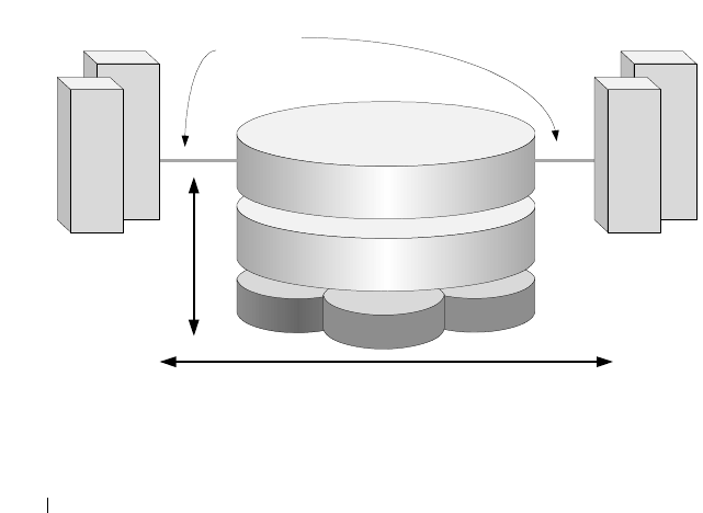
860 Configuring Connectivity Fault Management
IEEE Std. 802.3 LAN, Dot1ag addresses fault diagnosis at the service layer
across networks comprising multiple LANs, including LANs other than 802.3
media.
How Does Dot1ag Work Across a Carrier Network?
A typical metropolitan area network comprises operator, service provider, and
customer networks. To suit this business model, CFM relies on a functional
model of hierarchical maintenance domains (MDs). These domains are
assigned a unique MD level. There is a maximum of 8 levels, which can be
nested but cannot overlap. Each organization can have its own maintenance
domain. The MD level limits administrator access to the appropriate domain.
Figure 26-1 depicts three domains: the customer subscribes to the services of
a provider, who, in turn, subscribes to the services of two operators. This
scenario is a likely one, since no operator has complete coverage of a large
region. A service instance would span the provider network covering one or
more operators. Every domain has its own network management system.
Dot1ag defines OAM services that operate across these domains (the vertical
arrow) and within them (the horizontal arrow)
Figure 26-1. Organization of Domains
Entities at different levels have different responsibilities. For example, the
lower level (operator) overlooks a subset of the network in detail and provides
information about its status to its higher levels such as the provider level).
Provider
Customer
Operator 1 Operator 3
Operator 2
Customer
Site 1 Customer
Site 2
Access
Links,
802.3ah
802.1ag

Configuring Connectivity Fault Management 861
Higher levels have a broader, but less detailed, view of the network. As a
result, a provider could include multiple operators, provided that the domains
never intersect. The operator transparently passes frames from the customer
and provider, and the customer does not see the operator frames. Multiple
levels within a domain (say, operator) are supported for flexibility.
What Entities Make Up a Maintenance Domain?
Dot1ag defines three primary entities that make up the maintenance domain:
Maintenance End Points (MEPs), Maintenance Intermediate Points (MIPs),
and Maintenance Associations (MAs).
MEPs, and MIPs
MEPs and MIPs are software or sometimes hardware per-service entities
where CFM functionalities are present.
• MEPs define the boundary of a maintenance domain. They initiate and
respond to CFM messages. MEPs prevent the leaking of CFM messages
between domains (for example, among operators or between operators and
customers). Each MEP has a configurable unique identifier (MEPID) in a
maintenance domain.
MEPs periodically issue Continuity Check Messages (CCM) to discover
each other and issue SNMP traps to report connectivity losses or
malformed or incorrect CCMs.
A MEP can be defined as “down MEP” or an “up MEP”. A down MEPs
reside in a bridge that transmits CFM PDUs towards, and receives them
from, the direction of the LAN. An up MEP resides in a bridge that
transmits CFM PDUs towards, and receives them from, the direction of
the Bridge Relay Entity.
• MIPs are entities within a domain that enable the outer domain to achieve
end-to-end connectivity checks. MIPs passively receive CFM messages and
respond back to the originating MEP.
NOTE: An entity at the boundary of maintenance domain that offers
connectivity and other services to systems outside the domain is referred to
as a Domain Service Access Point (DoSAP). A MEP is a type of DoSAP
whose services relate to connectivity fault management.
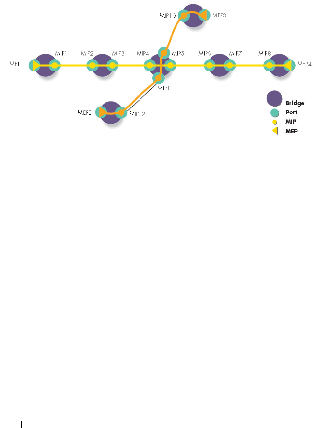
862 Configuring Connectivity Fault Management
Figure 26-2 depicts two MEPs and the MIPs that connect them in a
maintenance domain.
Figure 26-2. Maintenance Endpoints and Intermediate Points
Maintenance Associations
An MA is a logical connection between one or more MEPs that enables
monitoring a particular service instance. Each MA is associated with a unique
SVLAN ID. An MA is identified by a maintenance association ID. All MEPs
in the MA are assigned the maintenance identifier (MAID) for the
association.
An MD consists of one or more MAs at the same domain level.
Figure 26-3 depicts one provider-level domain and two operator-level
domains. Dot1ag operation for a service instance is indicated by the path that
traverses the different domains to provide the end-to-end connectivity fault
management for the service.
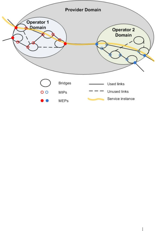
Configuring Connectivity Fault Management 863
Figure 26-3. Provider View for Service Level OAM
What is the Administrator’s Role?
On the switch, the administrator configures the customer-level maintenance
domains, associations, and endpoints used to participate in Dot1ag services
with other switches connected through the provider network. The
Administrator can also use utilities to troubleshoot connectivity faults when
reported via SNMP traps. All the domains within the customer domain
should use different domain levels.
Configuration Tasks
The administrator defines the maintenance domains by configuring the
domain level (from 0–7) and a name. For each domain, the administrator
defines maintenance associations that are specified by a SVLAN ID and an
MA name. Then the administrator defines the switch ports that serve as
MEPs for a service instance and as MIPs within a domain.

864 Configuring Connectivity Fault Management
Troubleshooting Tasks
In the event of a connectivity loss between MEPs, the administrator can
perform path discovery, similar to traceroute, from one MEP to any MEP or
MIP in a maintenance domain using Link Trace Messages (LTMs). The
connectivity loss is narrowed down using path discovery and is verified using
Loop-back Messages (LBMs), which are similar to ping operations in IP
networks.
Default Dot1ag Values
Dot1ag service are disabled by default and no maintenance domains,
associations, or endpoints are configured by default.
Table 26-1 shows the global default values for Dot1ag.
When you configure an association between a VLAN and a maintenance
domain, the following default value applies:
When you associate endpoints with SVLAN IDs, the following default values
apply and are configurable:
Table 26-1. Dot1ag Global Defaults
Parameter Default Value
CFM Admin Mode Disabled
Archive Hold Time 600 seconds
Table 26-2. MA Configuration Defaults
Parameter Default Value
Continuity Check Message (CCM)
Interval
1 second
Table 26-3. MEP Configuration Defaults
Parameter Default Value
MEP Active False
Continuity Check Interval (CCI)
Enabled
True
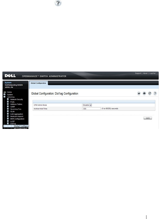
Configuring Connectivity Fault Management 865
Configuring Dot1ag (Web)
This section provides information about the OpenManage Switch
Administrator pages for configuring and monitoring Dot1ag features on a
Dell Networking N2000, N3000, and N4000 series switches. For details about
the fields on a page, click at the top of the page.
Dot1ag Global Configuration
Use the
Global Configuration page to enable and disable the Dot1ag admin
mode and to configure the time after which inactive RMEP messages are
removed from the MEP database.
To display the
page, click Switching
→
Dot1ag
→
Global Configuration in
the tree view.
Figure 26-4. Dot1ag Global Configuration
Dot1ag MD Configuration
Use the
MD Configuration page to configure maintenance domain levels
and names.
To display the
page, click Switching
→
Dot1ag
→
MD Configuration in the
tree view.

866 Configuring Connectivity Fault Management
Figure 26-5. Dot1ag MD Configuration
Dot1ag MA Configuration
Use the
MA Configuration page to associate a maintenance domain level
with one or more VLAN ID, provide a name for each maintenance association
(MA), and to set the interval between continuity check messages sent by
MEPs for the MA.
To display the
page, click Switching
→
Dot1ag
→
MA Configuration in the
tree view.
Figure 26-6. Dot1ag MA Configuration

Configuring Connectivity Fault Management 867
To add an MA, click the Add link at the top of the page.
Dot1ag MEP Configuration
Use the
MEP Configuration page to define switch ports as Management End
Points. MEPs are configured per domain and per VLAN.
To display the
page, click Switching
→
Dot1ag
→
MEP Configuration in the
tree view.
Figure 26-7. Dot1ag MEP Configuration
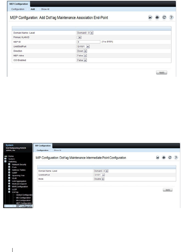
868 Configuring Connectivity Fault Management
To add a MEP, click the Add link at the top of the page. A VLAN must be
associated with the selected domain before you configure a MEP to be used
within an MA (see the MA Configuration page).
Dot1ag MIP Configuration
Use the
MIP Configuration page to define a switch port as an intermediate
bridge for a selected domain.
To display the
page, click Switching
→
Dot1ag
→
MIP Configuration in the
tree view.
Figure 26-8. Dot1ag MIP Configuration

Configuring Connectivity Fault Management 869
Dot1ag RMEP Summary
Use the
RMEP Summary page to view information on remote MEPs that the
switch has learned through CFM PDU exchanges with MEPs on the switch.
To display the
page, click Switching
→
Dot1ag
→
RMEP Summary in the
tree view.
Figure 26-9. Dot1ag RMEP Summary
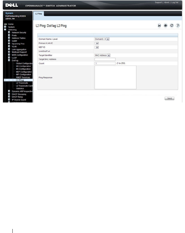
870 Configuring Connectivity Fault Management
Dot1ag L2 Ping
Use the
L2 Ping page to generate a loopback message from a specified MEP.
The MEP can be identified by the MEP ID or by its MAC address.
To display the
page, click Switching
→
Dot1ag
→
L2 Ping in the tree view.
Figure 26-10. Dot1ag L2 Ping
Dot1ag L2 Traceroute
Use the
L2 Traceroute page to generate a Link Trace message from a specified
MEP. The MEP can be specified by the MAC address, or by the remote MEP
ID.
To display the
page, click Switching
→
Dot1ag
→
L2 Traceroute in the tree
view.
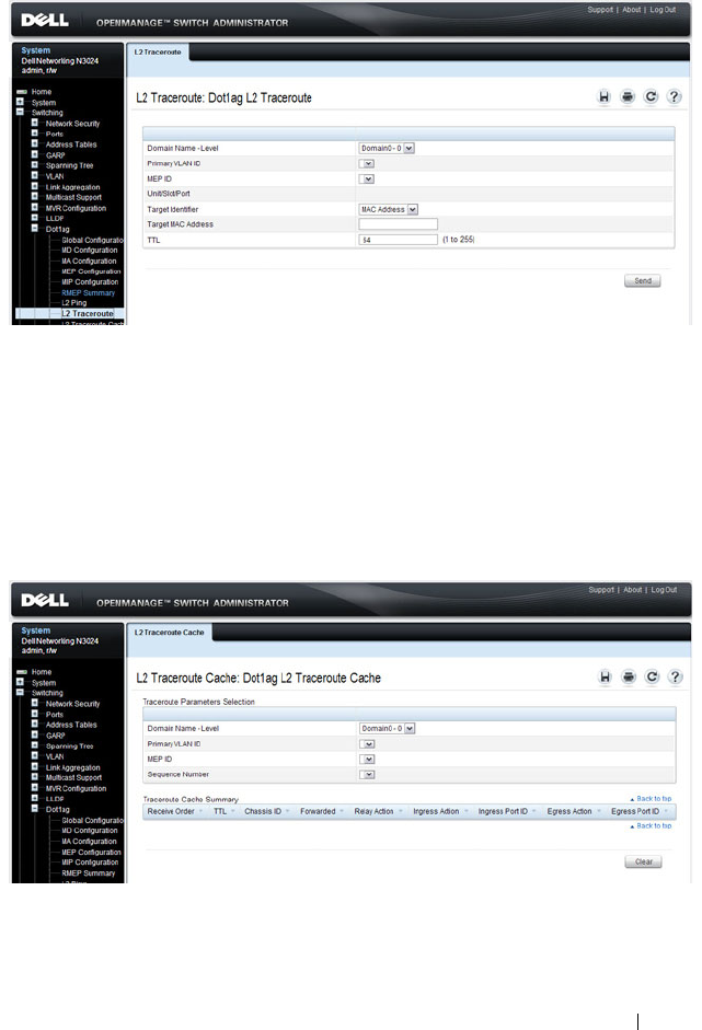
Configuring Connectivity Fault Management 871
Figure 26-11. Dot1ag L2 Traceroute
Dot1ag L2 Traceroute Cache
Use the
L2 Traceroute Cache page to view link traces retained in the link
trace database.
To display the
page, click Switching
→
Dot1ag
→
L2 Traceroute Cache in
the tree view.
Figure 26-12. Dot1ag L2 Traceroute Cache
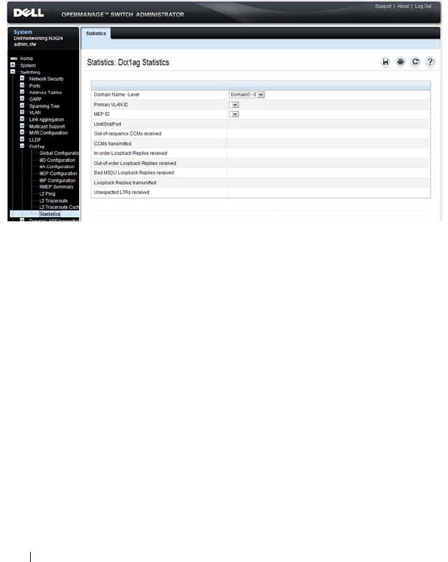
872 Configuring Connectivity Fault Management
Dot1ag Statistics
Use the
Statistics page to view Dot1ag information for a selected domain and
VLAN ID.
To display the
page, click Switching
→
Dot1ag
→
Statistics in the tree view.
Figure 26-13. Dot1ag Statistics

Configuring Connectivity Fault Management 873
Configuring Dot1ag (CLI)
This section provides information about the commands you use to configure
Dot1ag settings on the switch. For more information about the commands,
see the
Dell Networking N2000, N3000, and N4000 Series Switches CLI
Reference Guide
at support.dell.com/manuals.
Configuring Dot1ag Global Settings and Creating Domains
Beginning in Privileged Exec mode, use the following commands to configure
CFM settings and to view global status and domain information.
CLI Command Description
configure Enter global configuration mode.
ethernet cfm enable Enables connectivity fault management services.
ethernet cfm mep archive-
hold-time
time
Set the time interval (range: 1–65535 seconds) after
which inactive RMEPs are removed.
ethernet cfm cc level
level
vlan
vlan-id
interval {1 | 10 | 60 |
600}
Configure the Continuity Check Message (CCM)
transmit interval for the specified VLAN.
ethernet cfm domain
name
level
level
Create a maintenance domain (MD) by assigning a
name and level (0–7), and enter Maintenance
Domain Config mode for that MD.
service
name
vlan
vlan-id
Create a maintenance association (MA) within the
current MD by associating it with a VLAN and
naming the association (as a service instance).
exit Exit to privileged Exec Mode
show ethernet cfm domain
brief
Display the configured parameters in the
Maintenance Domain.

874 Configuring Connectivity Fault Management
Configuring MEP Information
Beginning in Privileged Exec mode, use the following commands to configure
the mode and view related settings.
CLI Command Description
configure Enter global configuration mode.
interface
interface
Enter Interface Config mode for the specified
interface, where
interface
is replaced by
gigabitethernet
unit/slot/port
, or tengigabitethernet
unit/slot/port
.
ethernet cfm mep enable level
level
vlan
vlan-id
mpid
mep-id
Define the port as a maintenance endpoint (MEP)
and associate it with an SVLAN in a domain. When
the MEP is enabled, it will generate CCM messages.
ethernet cfm mep level
level
direction {up | down} mpid
mep-id
vlan
vlan-id
Enable a MEP at the specified level and direction.
ethernet cfm mep active Set the administrative state of the MEP to active.
ethernet cfm mip level
level
Create a MIP at the specified level on the interface.
exit Exit to privileged Exec Mode
show ethernet cfm
maintenance–points
Add the keywords local domain, local interface,
local level, remote domain, or remote level to show
information on local or remote endpoints.
show ethernet cfm statistics Display statistics per MEP.

Configuring Connectivity Fault Management 875
Dot1ag Ping and Traceroute
Beginning in Privileged Exec mode, use the following commands to help
identify and troubleshoot Ethernet CFM settings.
CLI Command Description
ping ethernet cfm mac
mac-
addr
Generate a loopback message from the MEP with
the specified MAC address.
ping ethernet cfm
remote–mpid
mep-id
Generate a loopback message from the MEP with
the specified MEP ID.
traceroute ethernet cfm mac
mac-addr
Generate a Link Trace message from the MEP with
the specified MAC address.
traceroute ethernet cfm
remote–mpid
mep-id
Generate a Link Trace message from the MEP with
the specified MEP ID.
show ethernet cfm
traceroute–cache
Show the link trace database.

876 Configuring Connectivity Fault Management
Dot1ag Configuration Example
In the following example, the switch at the customer site is part of a Metro
Ethernet network that is bridged to remote sites through a provider network.
A service VLAN (SVID 200) identifies a particular set of customer traffic on
the provider network.
Figure 26-14. Dot1ag Configuration for a Metro Ethernet Customer Network
To configure the switch:
1
Enable CFM globally on the switch, and then create a level-6 management
domain named CustDom for end-to-end CFM on the Metro Ethernet
network. VLAN 200 is associated with this domain.
console#config
console(config)#ethernet cfm enable
console(config)#
ethernet cfm domain CustDom level 6
console(config-cfm-mdomain)#service vlan vlan 200
console(config-cfm-mdomain)#exit

Configuring Connectivity Fault Management 877
2
Configure port 1/0/5 as an MEP for service VLAN 200 so that the port can
exchange CFM PDUs with its counterpart MEPs on the customer
network. The port is first configured as a MEP with MEP ID 20 on domain
level 6 for VLAN 200. Then the port is enabled and activated as a MEP.
console(config)#interface gigabitethernet 1/0/5
console(config-if-Gi1/0/5)#ethernet cfm mep level 6
direction down mpid 20 vlan 200
console(config-if-Gi1/0/5)#ethernet cfm mep
enabled level 6 vlan 200 mpid 20
console(config-if-Gi1/0/5)#ethernet cfm mep active
level 6 vlan 200 mpid 20
console(config-if-Gi1/0/5)#exit
3
On an intermediate switch, configure the MIP for the customer domain
and enable CFM services on the CustDom domain to include local
network devices.

878 Configuring Connectivity Fault Management

Snooping and Inspecting Traffic 879
27
Snooping and Inspecting Traffic
This chapter describes Dynamic Host Configuration Protocol (DHCP)
Snooping, IP Source Guard (IPSG), and Dynamic ARP Inspection (DAI),
which are layer 2 security features that examine traffic to help prevent
accidental and malicious attacks on the switch or network.
The topics covered in this chapter include:
• Traffic Snooping and Inspection Overview
• Default Traffic Snooping and Inspection Values
• Configuring Traffic Snooping and Inspection (Web)
• Configuring Traffic Snooping and Inspection (CLI)
• Traffic Snooping and Inspection Configuration Examples
Traffic Snooping and Inspection Overview
DHCP Snooping is a security feature that monitors DHCP messages between
a DHCP client and DHCP server to filter harmful DHCP messages and to
build a bindings database. The IPSG and DAI features use the DHCP
Snooping bindings database to help enforce switch and network security.
IP Source Guard allows the switch to drop incoming packets that do not
match a binding in the bindings database. Dynamic ARP Inspection allows
the switch to drop ARP packets whose sender MAC address and sender IP
address do not match an entry in the DHCP snooping bindings database.
DHCP Snooping and IPSG are supported for both IPv4 and IPv6. DAI is
supported for IPv4 only, as IPv6 does not use ARP.

880 Snooping and Inspecting Traffic
What Is DHCP Snooping?
Dynamic Host Configuration Protocol (DHCP) Snooping is a security feature
that monitors DHCP messages between a DHCP client and DHCP server to
accomplish the following tasks:
• Filter harmful DHCP messages
• Build a bindings database with entries that consist of the following
information:
• MAC address
• IP address
• VLAN ID
•Client port
Entries in the bindings database are considered to be authorized network
clients.
DHCP snooping can be enabled on VLANs, and the trust status (trusted or
untrusted) is specified on individual physical ports or LAGS that are
members of a VLAN. When a port or LAG is configured as untrusted, it could
potentially be used to launch a network attack. DHCP servers must be
reached through trusted ports.
DHCP snooping enforces the following security rules:
• DHCP packets from a DHCP server (DHCPOFFER, DHCPACK,
DHCPNAK, DHCPRELEASEQUERY) are dropped if they are received on
an untrusted port.
• DHCPRELEASE and DHCPDECLINE messages are dropped if the MAC
addresses in the snooping database, but the binding's interface is other
than the interface where the message was received.
• On untrusted interfaces, the switch drops DHCP packets with a source
MAC address that does not match the client hardware address. This is a
configurable option.
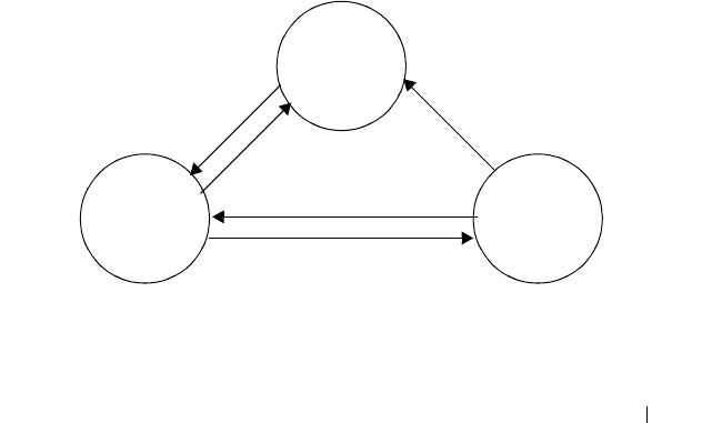
Snooping and Inspecting Traffic 881
How Is the DHCP Snooping Bindings Database Populated?
The DHCP snooping application uses DHCP messages to build and maintain
the binding’s database. DHCP snooping creates a tentative binding from
DHCP DISCOVER and REQUEST messages. Tentative bindings tie a client
to a port (the port where the DHCP client message was received). Tentative
bindings are completed when DHCP snooping learns the client’s IP address
from a DHCP ACK message on a trusted port. DHCP snooping removes
bindings in response to DECLINE, RELEASE, and NACK messages. The
DHCP snooping application ignores the ACK messages as a reply to the
DHCP Inform messages received on trusted ports. You can also enter static
bindings into the binding database.
When a switch learns of new bindings or loses bindings, the switch
immediately updates the entries in the database. The switch also updates the
entries in the binding file. The frequency at which the file is updated is based
on a configurable delay, and the updates are batched.
If the absolute lease time of the snooping database entry expires, that entry is
removed. Make sure the system time is consistent across the reboots.
Otherwise, the snooping entries will not expire properly. If a host sends a
DHCP release while the switch is rebooting, when the switch receives the
DHCP discovery or request, the client’s binding goes to the tentative binding
as shown in Figure 27-1.
Figure 27-1. DHCP Binding
The binding database includes data for clients only on untrusted ports.
Tentative
Binding
Complete
Binding
No Binding
ACK
Discover
Discover
Request
Release
NACK
Decline
NACK

882 Snooping and Inspecting Traffic
DHCP Snooping and VLANs
DHCP snooping forwards valid DHCP client messages received on non-
routing VLANs. The message is forwarded on all trusted interfaces in the
VLAN.
DHCP snooping can be configured on switching VLANs and routing VLANs.
When a DHCP packet is received on a routing VLAN, the DHCP snooping
application applies its filtering rules and updates the bindings database. If a
client message passes filtering rules, the message is placed into the software
forwarding path where it may be processed by the DHCP relay agent, the
local DHCP server, or forwarded as an IP packet.
DHCP Snooping Logging and Rate Limits
The DHCP snooping application processes incoming DHCP messages. For
DHCPRELEASE and DHCPDECLINE messages, the application compares
the receive interface and VLAN with the client interface and VLAN in the
bindings database. If the interfaces do not match, the application logs the
event and drops the message. For valid client messages, DHCP snooping
compares the source MAC address to the DHCP client hardware address.
When there is a mismatch, DHCP snooping drops the packet and generates a
log message if logging of invalid packets is enabled.
If DHCP relay co-exists with DHCP snooping, DHCP client messages are
sent to DHCP relay for further processing.
To prevent DHCP packets from being used as a DoS attack when DHCP
snooping is enabled, the snooping application enforces a rate limit for DHCP
packets received on interfaces. DHCP rate limiting can be configured on both
trused and untrusted interfaces. DHCP snooping monitors the receive rate on
each interface separately. If the receive rate exceeds a configurable limit,
DHCP snooping diagnostically disables the interface. Administrative
intervention is necessary to enable the port, either by using the no shutdown
command in Interface Config mode or on the Switching
→
Ports
→
Port
Configuration page. Use the ip dhcp snooping limit none command to
disable diagnostic disabling of the port due to DHCP snooping.

Snooping and Inspecting Traffic 883
What Is IP Source Guard?
IPSG is a security feature that filters IP packets based on source ID. This
feature helps protect the network from attacks that use IP address spoofing to
compromise or overwhelm the network.
The source ID may be either the source IP address or a {source IP address,
source MAC address} pair. You can configure:
• Whether enforcement includes the source MAC address
• Static authorized source IDs
The DHCP snooping bindings database and static IPSG entries identify
authorized source IDs. IPSG can be enabled on physical and LAG ports.
If you enable IPSG on a port where DHCP snooping is disabled or where
DHCP snooping is enabled but the port is trusted, all IP traffic received on
that port is dropped depending on the admin-configured IPSG entries.
IPSG and Port Security
IPSG interacts with port security, also known as port MAC locking, (see "Port
Security (Port-MAC Locking)" on page 539) to enforce the source MAC
address. Port security controls source MAC address learning in the layer 2
forwarding database (MAC address table). When a frame is received with a
previously unlearned source MAC address, port security queries the IPSG
feature to determine whether the MAC address belongs to a valid binding.
If IPSG is disabled on the ingress port, IPSG replies that the MAC is valid. If
IPSG is enabled on the ingress port, IPSG checks the bindings database. If
the MAC address is in the bindings database and the binding matches the
VLAN the frame was received on, IPSG replies that the MAC is valid. If the
MAC is not in the bindings database, IPSG informs port security that the
frame is a security violation.
In the case of an IPSG violation, port security takes whatever action it
normally takes upon receipt of an unauthorized frame. Port security limits the
number of MAC addresses to a configured maximum. If the limit
n
is less
than the number of stations
m
in the bindings database, port security allows
only
n
stations to use the port. If
n > m
, port security allows only the stations
in the bindings database. For information about configuring the Port Security
feature, see "Configuring Port and System Security" on page 503.

884 Snooping and Inspecting Traffic
What is Dynamic ARP Inspection?
Dynamic ARP Inspection (DAI) is a security feature that rejects invalid and
malicious ARP packets. DAI prevents a class of man-in-the-middle attacks
where an unfriendly station intercepts traffic for other stations by poisoning
the ARP caches of its unsuspecting neighbors. The malicious attacker sends
ARP requests or responses mapping another station’s IP address to its own
MAC address.
When DAI is enabled, the switch drops ARP packets whose sender MAC
address and sender IP address do not match an entry in the DHCP snooping
bindings database. You can optionally configure additional ARP packet
validation.
When DAI is enabled on a VLAN, DAI is enabled on the interfaces (physical
ports or LAGs) that are members of that VLAN. Individual interfaces are
configured as trusted or untrusted. The trust configuration for DAI is
independent of the trust configuration for DHCP snooping.
Optional DAI Features
If the network administrator has configured the option, DAI verifies that the
sender MAC address equals the source MAC address in the Ethernet header.
There is a configurable option to verify that the target MAC address equals
the destination MAC address in the Ethernet header. This check applies only
to ARP responses, since the target MAC address is unspecified in ARP
requests. You can also enable IP address checking. When this option is
enabled, DAI drops ARP packets with an invalid IP address. The following IP
addresses are considered invalid:
•0.0.0.0
• 255.255.255.255
• all IP multicast addresses
• all class E addresses (240.0.0.0/4)
• loopback addresses (in the range 127.0.0.0/8)
DAI can also be configured to rate-limit ARP requests on untrusted
interfaces. If the configured rate is exceeded, DAI diagnostically disables the
port on which the rate limit was exceeded. Use the no shutdown command to

Snooping and Inspecting Traffic 885
re-enable the port. DAI rate limiting cannot be enabled on trusted interfaces.
Use the no ip arp inspection limit command to disable diagnostic disabling
of untrused ports due to DAI.
Why Is Traffic Snooping and Inspection Necessary?
DHCP Snooping, IPSG, and DAI are security features that can help protect
the switch and the network against various types of accidental or malicious
attacks. It might be a good idea to enable these features on ports that provide
network access to hosts that are in physically unsecured locations or if
network users connect nonstandard hosts to the network.
For example, if an employee unknowingly connects a workstation to the
network that has a DHCP server, and the DHCP server is enabled, hosts that
attempt to acquire network information from the legitimate network DHCP
server might obtain incorrect information from the rogue DHCP server.
However, if the workstation with the rogue DHCP server is connected to a
port that is configured as untrusted and is a member of a DHCP Snooping-
enabled VLAN, the port discards the DHCP server messages.
Default Traffic Snooping and Inspection Values
DHCP snooping is disabled globally and on all VLANs by default. Ports are
untrusted by default.
Table 27-1. Traffic Snooping Defaults
Parameter Default Value
DHCP snooping mode Disabled
DHCP snooping VLAN mode Disabled on all VLANs
Interface trust state Disabled (untrusted)
DHCP logging invalid packets Disabled
DHCP snooping rate limit 15 packets per second
DHCP snooping burst interval 1 second
DHCP snooping binding database
storage
Local
DHCP snooping binding database
write delay
300 seconds

886 Snooping and Inspecting Traffic
Static DHCP bindings None configured
IPSG mode Disabled on all interfaces
IPSG port security Disabled on all interfaces
Static IPSG bindings None configured
DAI validate source MAC Disabled
DAI validate destination MAC Disabled
DAI validate IP Disabled
DAI trust state Disabled (untrusted)
DAI Rate limit Disabled
DAI Burst interval 1 second
DAI mode Disabled on all VLANs
DAI logging invalid packets Disabled
DAI ARP ACL None configured
DAI Static flag Disabled (validation by ARP ACL and DHCP
snooping binding database)
Table 27-1. Traffic Snooping Defaults (Continued)
Parameter Default Value
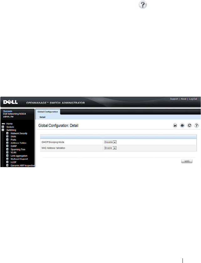
Snooping and Inspecting Traffic 887
Configuring Traffic Snooping and Inspection
(Web)
This section provides information about the OpenManage Switch
Administrator pages for configuring and monitoring DHCP snooping, IPSG,
and DAI features on a Dell Networking N2000, N3000, and N4000 series
switches. For details about the fields on a page, click at the top of the
page.
DHCP Snooping Configuration
Use the DHCP Snooping Configuration page to control the DHCP
Snooping mode on the switch and to specify whether the sender MAC
Address for DHCP Snooping must be validated.
To access the DHCP Snooping Configuration page, click Switching
→
DHCP Snooping
→
Global Configuration in the navigation panel.
Figure 27-2. DHCP Snooping Configuration
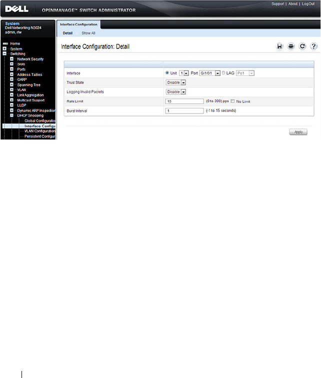
888 Snooping and Inspecting Traffic
DHCP Snooping Interface Configuration
Use the DHCP Snooping Interface Configuration page to configure the
DHCP Snooping settings on individual ports and LAGs.
To access the DHCP Snooping Interface Configuration page, click
Switching
→
DHCP Snooping
→
Interface Configuration in the navigation
panel.
Figure 27-3. DHCP Snooping Interface Configuration
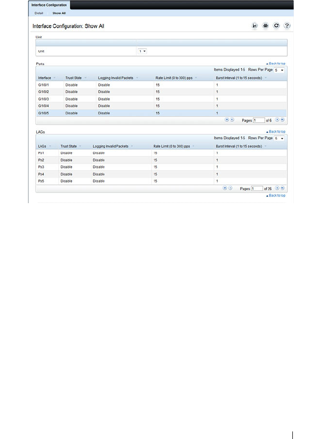
Snooping and Inspecting Traffic 889
To view a summary of the DHCP snooping configuration for all interfaces,
click Show All.
Figure 27-4. DHCP Snooping Interface Configuration Summary
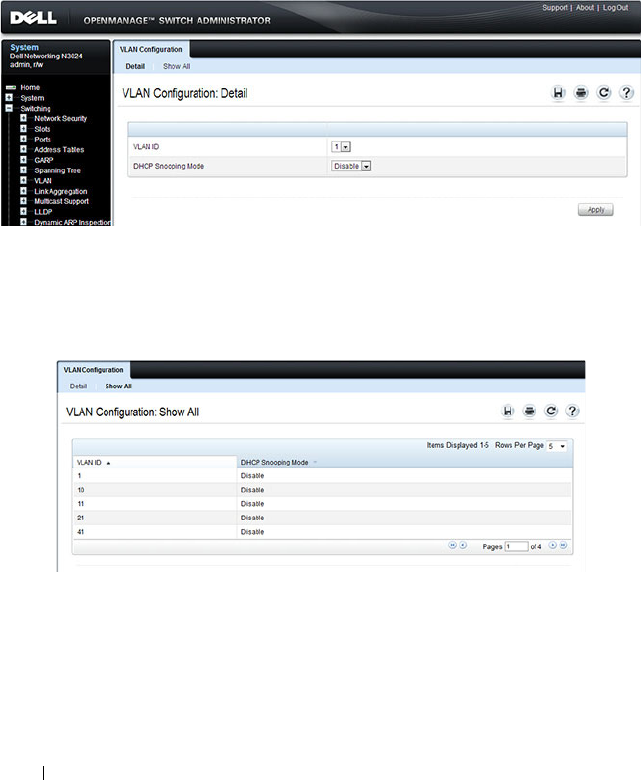
890 Snooping and Inspecting Traffic
DHCP Snooping VLAN Configuration
Use the DHCP Snooping VLAN Configuration page to control the DHCP
snooping mode on each VLAN.
To access the DHCP Snooping VLAN Configuration page, click Switching
→
DHCP Snooping
→
VLAN Configuration in the navigation panel.
Figure 27-5. DHCP Snooping VLAN Configuration
To view a summary of the DHCP snooping status for all VLANs, click Show
All.
Figure 27-6. DHCP Snooping VLAN Configuration Summary
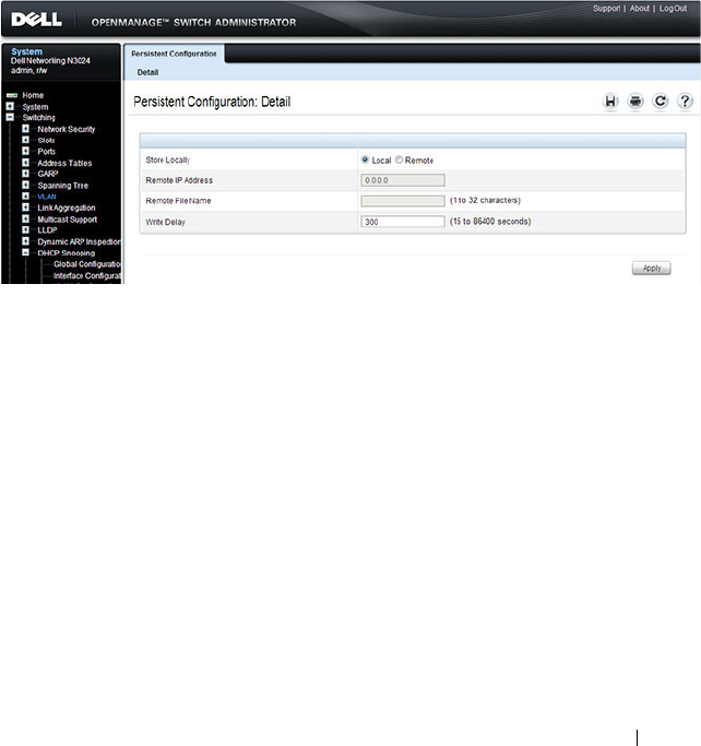
Snooping and Inspecting Traffic 891
DHCP Snooping Persistent Configuration
Use the DHCP Snooping Persistent Configuration page to configure the
persistent location of the DHCP snooping database. The bindings database
can be stored locally on the switch or on a remote system somewhere else in
the network. The switch must be able to reach the IP address of the remote
system to send bindings to a remote database.
To access the DHCP Snooping Persistent Configuration page, click
Switching
→
DHCP Snooping
→
Persistent Configuration in the navigation
panel.
Figure 27-7. DHCP Snooping Persistent Configuration
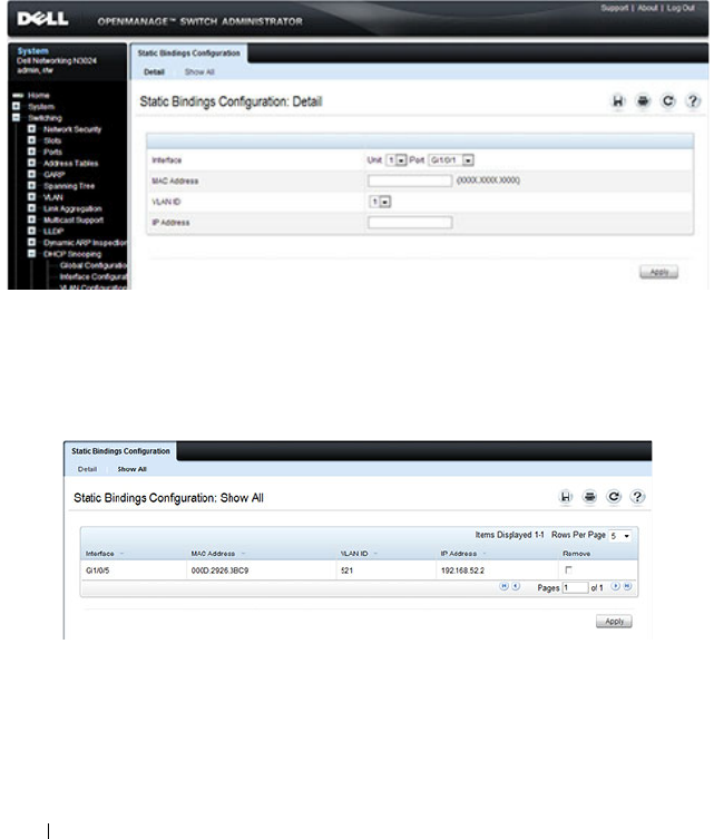
892 Snooping and Inspecting Traffic
DHCP Snooping Static Bindings Configuration
Use the DHCP Snooping Static Bindings Configuration page to add static
DHCP bindings to the binding database.
To access the DHCP Snooping Static Bindings Configuration page, click
Switching
→
DHCP Snooping
→
Static Bindings Configuration in the
navigation panel.
Figure 27-8. DHCP Snooping Static Bindings Configuration
To view a summary of the DHCP snooping status for all VLANs, click Show
All.
Figure 27-9. DHCP Snooping Static Bindings Summary
To remove a static binding, select the Remove checkbox associated with the
binding and click Apply.
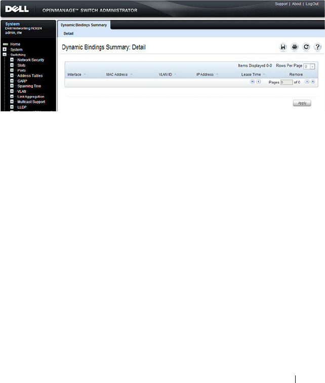
Snooping and Inspecting Traffic 893
DHCP Snooping Dynamic Bindings Summary
The DHCP Snooping Dynamic Bindings Summary lists all the DHCP
snooping dynamic binding entries learned on the switch ports.
To access the DHCP Snooping Dynamic Bindings Summary page, click
Switching
→
DHCP Snooping
→
Dynamic Bindings Summary in the
navigation panel.
Figure 27-10. DHCP Snooping Dynamic Bindings Summary
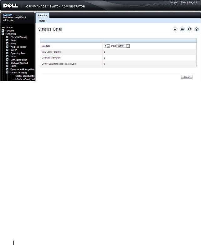
894 Snooping and Inspecting Traffic
DHCP Snooping Statistics
The DHCP Snooping Statistics page displays DHCP snooping interface
statistics.
To access the DHCP Snooping Statistics page, click Switching
→
DHCP
Snooping
→
Statistics in the navigation panel.
Figure 27-11. DHCP Snooping Statistics
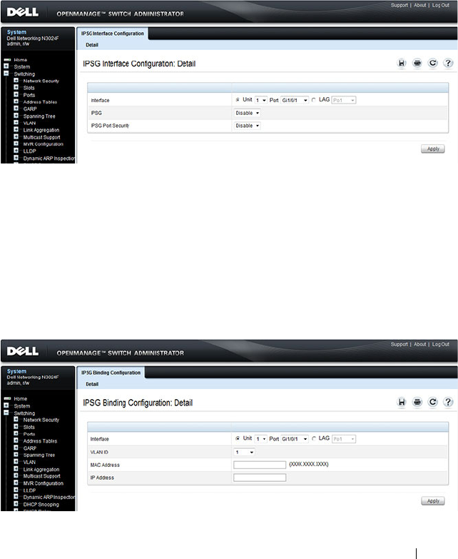
Snooping and Inspecting Traffic 895
IPSG Interface Configuration
Use the IPSG Interface Configuration page to configure IPSG on an
interface.
To access the IPSG Interface Configuration page, click Switching
→
IP
Source Guard
→
IPSG Interface Configuration in the navigation panel.
Figure 27-12. IPSG Interface Configuration
IPSG Binding Configuration
Use the IPSG Binding Configuration page displays DHCP snooping
interface statistics.
To access the IPSG Binding Configuration page, click Switching
→
IP
Source Guard
→
IPSG Binding Configuration in the navigation panel.
Figure 27-13. IPSG Binding Configuration
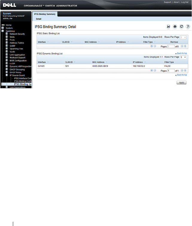
896 Snooping and Inspecting Traffic
IPSG Binding Summary
The IPSG Binding Summary page displays the IPSG Static binding list and
IPSG dynamic binding list (the static bindings configured in Binding
configuration page).
To access the IPSG Binding Summary page, click Switching
→
IP Source
Guard
→
IPSG Binding Summary in the navigation panel.
Figure 27-14. IPSG Binding Summary
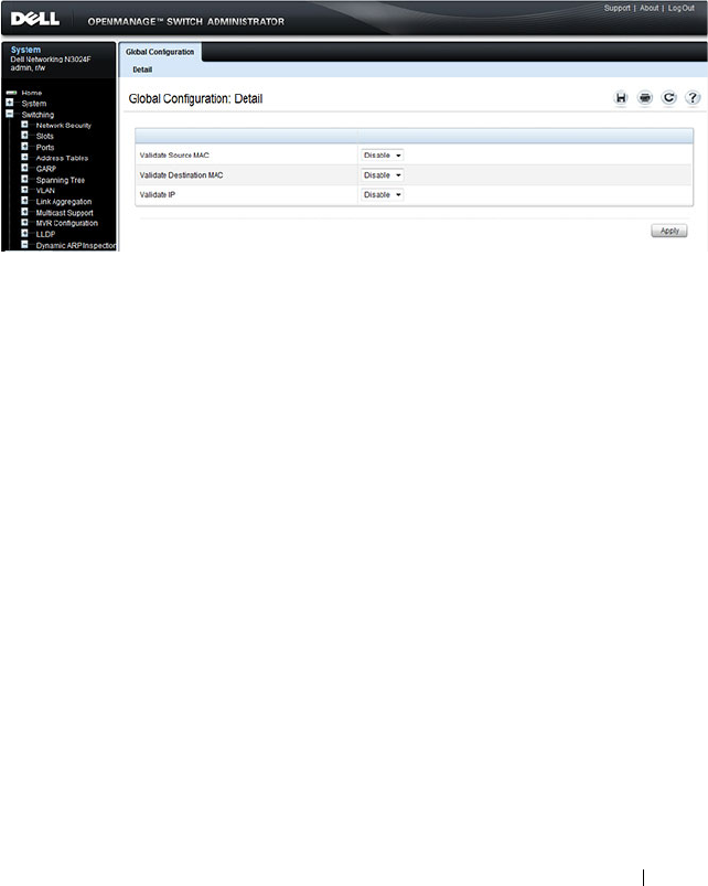
Snooping and Inspecting Traffic 897
DAI Global Configuration
Use the DAI Configuration page to configure global DAI settings.
To display the DAI Configuration page, click Switching
→
Dynamic ARP
Inspection
→
Global Configuration in the navigation panel.
Figure 27-15. Dynamic ARP Inspection Global Configuration
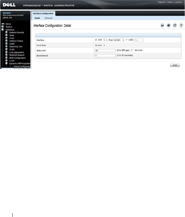
898 Snooping and Inspecting Traffic
DAI Interface Configuration
Use the DAI Interface Configuration page to select the DAI Interface for
which information is to be displayed or configured.
To display the DAI Interface Configuration page, click Switching
→
Dynamic ARP Inspection
→
Interface Configuration in the navigation
panel.
Figure 27-16. Dynamic ARP Inspection Interface Configuration
To view a summary of the DAI status for all interfaces, click Show All.
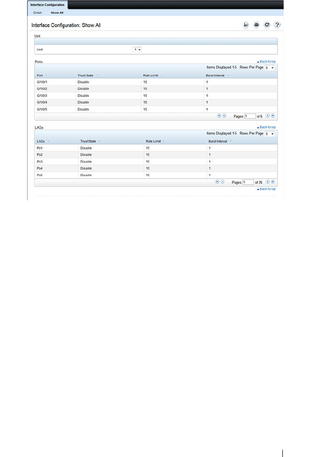
Snooping and Inspecting Traffic 899
Figure 27-17. DAI Interface Configuration Summary
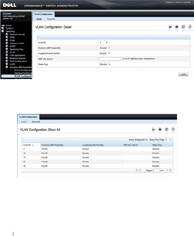
900 Snooping and Inspecting Traffic
DAI VLAN Configuration
Use the DAI VLAN Configuration page to select the VLANs for which
information is to be displayed or configured.
To display the DAI VLAN Configuration page, click Switching
→
Dynamic
ARP Inspection
→
VLAN Configuration in the navigation panel.
Figure 27-18. Dynamic ARP Inspection VLAN Configuration
To view a summary of the DAI status for all VLANs, click Show All.
Figure 27-19. Dynamic ARP Inspection VLAN Configuration Summary
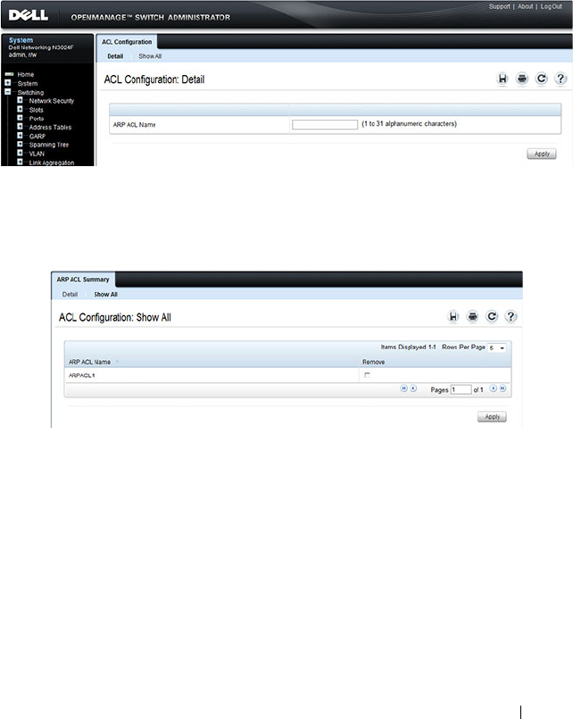
Snooping and Inspecting Traffic 901
DAI ACL Configuration
Use the DAI ACL Configuration page to add or remove ARP ACLs.
To display the DAI ACL Configuration page, click Switching
→
Dynamic
ARP Inspection
→
ACL Configuration in the navigation panel.
Figure 27-20. Dynamic ARP Inspection ACL Configuration
To view a summary of the ARP ACLs that have been created, click Show All.
Figure 27-21. Dynamic ARP Inspection ACL Summary
To remove an ARP ACL, select the Remove checkbox associated with the
ACL and click Apply.
DAI ACL Rule Configuration
Use the DAI ARP ACL Rule Configuration page to add or remove DAI ARP
ACL Rules.
To display the DAI ARP ACL Rule Configuration page, click Switching
→
Dynamic ARP Inspection
→
ACL Rule Configuration in the navigation
panel.
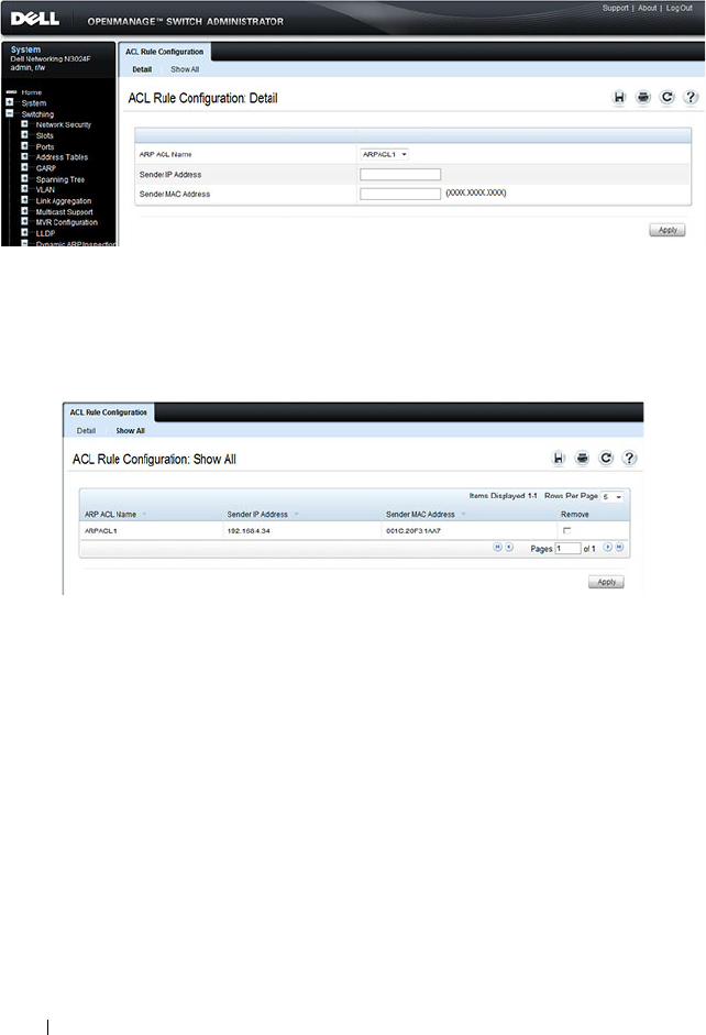
902 Snooping and Inspecting Traffic
Figure 27-22. Dynamic ARP Inspection Rule Configuration
To view a summary of the ARP ACL rules that have been created, click Show
All.
Figure 27-23. Dynamic ARP Inspection ACL Rule Summary
To remove an ARP ACL rule, select the Remove checkbox associated with the
rule and click Apply.
DAI Statistics
Use the DAI Statistics page to display the statistics per VLAN.
To display the DAI Statistics page, click Switching
→
Dynamic ARP
Inspection
→
Statistics in the navigation panel.

Snooping and Inspecting Traffic 903
Figure 27-24. Dynamic ARP Inspection Statistics

904 Snooping and Inspecting Traffic
Configuring Traffic Snooping and Inspection (CLI)
This section provides information about the commands you use to configure
DHCP snooping, IPSG, and DAI settings on the switch. For more
information about the commands, see the
Dell Networking N2000, N3000,
and N4000 Series Switches CLI Reference Guide
at
support.dell.com/manuals.
Configuring DHCP Snooping
Beginning in Privileged EXEC mode, use the following commands to
configure and view DHCP snooping settings.
Command Purpose
configure Enter global configuration mode.
ip dhcp snooping Enable DHCP snooping on the switch.
ipv6 dhcp snooping Enable IPv6 DHCP snooping on the switch.
ip dhcp snooping verify
mac-address
Enable the verification of the source MAC address with
the client MAC address in the received DHCP message.
ip dhcp snooping log-
invalid
Enable the logging of DHCP messages filtered by the
DHCP Snooping application.
ip dhcp snooping
binding mac-address
vlan vlan-id ip-address
interface interface
Configure a static binding in the DHCP snooping static
bindings database.
•
mac-address
—The client's MAC address.
•
vlan-id
—The number of the VLAN the client is
authorized to use.
•
ip-address
—The IP address of the client.
•
interface
—The interface on which the client is
authorized. The form is unit/port.
ip dhcp snooping
database {local |
tftp://
hostIP/filename
}
Configure the persistent storage location of the DHCP
snooping database.
•
hostIP
—The IP address of the remote host.
•
filename
—The name of the file for the database on the
remote host.

Snooping and Inspecting Traffic 905
ip dhcp snooping
database write-delay
seconds
Configure the interval, in seconds, at which the DHCP
Snooping database will be stored in persistent storage. The
number of seconds can range from 15–86400.
ip dhcp snooping limit
{none | rate
rate
[burst
interval
seconds
]}
Configure the maximum rate of DHCP messages allowed
on the switch at any given time.
•
rate
—The maximum number of packets per second
allowed (Range: 0–300 pps).
•
seconds
—The time allowed for a burst (Range: 1–15
seconds).
interface
interface
Enter interface configuration mode for the specified port
or LAG. The
interface
variable includes the interface type
and number, for example tengigabitethernet 1/0/3. For a
LAG, the interface type is port-channel.
You can also specify a range of ports with the interface
range command, for example, interface range
tengigabitethernet 1/0/8-12 configures interfaces 8, 9, 10,
11, and 12.
ip dhcp snooping trust Configure the interface (or range of interfaces) as a trusted
port. DHCP server messages are not filtered on trusted
ports.
exit Exit to Global Configuration mode.
interface [range] vlan
vlan id
Enter interface configuration mode for the specified
VLAN or range of VLANs.
CTRL + Z Exit to Privileged EXEC mode.
show ip dhcp snooping
[interfaces]
View the DHCP snooping global and per port
configuration.
show ip dhcp snooping
binding [{static |
dynamic}] [interface
port
] [vlan
vlan-id
]
View the entries in the DHCP snooping bindings database.
show ip dhcp snooping
database
View information about the persistent database
configuration.
show ip dhcp snooping
statistics
View the DHCP snooping statistics.
Command Purpose

906 Snooping and Inspecting Traffic
Configuring IP Source Guard
Beginning in Privileged EXEC mode, use the following commands to
configure IPSG settings on the switch.
clear ip dhcp snooping
statistics
Reset the DHCP snooping statistics to zero.
Command Purpose
configure Enter global configuration mode.
interface
interface
Enter interface configuration mode for the specified port
or LAG. The
interface
variable includes the interface type
and number, for example tengigabitethernet 1/0/3. For a
LAG, the interface type is port-channel.
You can also specify a range of ports with the interface
range command, for example, interface range
tengigabitethernet 1/0/8-12 configures interfaces 8, 9, 10,
11, and 12.
ip verify source [port-
security]
and
ipv6 verify source [port-
security]
Enable IPSG on the port or LAG to prevent packet
forwarding if the source IP address in the packet is not in
the DHCP snooping binding database. Use the optional
port-security keyword to also prevent packet forwarding if
the sender MAC address is not in forwarding database
table or the DHCP snooping binding database.
NOTE: To enforce filtering based on the source MAC
address, port security must also be enabled on the interface
by using the port security command in Interface
Configuration mode.
exit Exit to Global Config mode.
ip verify binding
mac_addr
vlan
vlan_id
ipaddr
interface
interface
and
ipv6 verify binding
mac_addr
vlan
vlan_id
ipaddr
interface
interface
Configure a static binding for IPSG.
Command Purpose

Snooping and Inspecting Traffic 907
Configuring Dynamic ARP Inspection
Beginning in Privileged EXEC mode, use the following commands to
configure DAI settings on the switch.
exit Exit to Privileged EXEC mode.
show ip verify interface
interface
View IPSG parameters for a specific port or LAG. The
interface
parameter includes the interface type
(gigabitethernet, tengigabitethernet, or port-channel)
and number.
show ip verify source
[interface
interface
]
View IPSG bindings configured on the switch or on a
specific port or LAG.
show ip source binding View IPSG bindings.
Command Purpose
configure Enter global configuration mode.
ip arp inspection vlan
vlan-range [logging]
Enable Dynamic ARP Inspection on a single VLAN or a
range of VLANs. Use the logging keyword to enable
logging of invalid packets.
ip arp inspection
validate {[src-mac] [dst-
mac] [ip]}
Enable additional validation checks like source MAC
address validation, destination MAC address validation, or
IP address validation on the received ARP packets.
Each command overrides the configuration of the
previous command. For example, if a command enables
source MAC address and destination validations and a
second command enables IP address validation only, the
source MAC address and destination MAC address
validations are disabled as a result of the second
command.
•
src-mac
—
For validating the source MAC address of an
ARP packet.
•
dst-mac
—
For validating the destination MAC address of
an ARP packet.
•
ip
—
For validating the IP address of an ARP packet.
Command Purpose

908 Snooping and Inspecting Traffic
arp access-list
acl-name
Create an ARP ACL with the specified name (1–31
characters) and enter ARP Access-list Configuration mode
for the ACL.
permit ip host
sender-ip
mac host
sender-mac
Configure a rule for a valid IP address and MAC address
combination used in ARP packet validation.
•
sender-ip
— Valid IP address used by a host.
•
sender-mac
—Valid MAC address in combination with
the above sender-ip used by a host.
exit Exit to Global Config mode.
ip arp inspection filter
acl-name
vlan
vlan-range
[static]
Configure the ARP ACL to be used for a single VLAN or a
range of VLANs to filter invalid ARP packets.
Use the static keyword to indicate that packets that do not
match a permit statement are dropped without consulting
the DHCP snooping bindings.
interface
interface
Enter interface configuration mode for the specified port
or LAG. The
interface
variable includes the interface type
and number, for example tengigabitethernet 1/0/3. For a
LAG, the interface type is port-channel.
You can also specify a range of ports with the interface
range command, for example, interface range
tengigabitethernet 1/0/8-12 configures interfaces 8, 9, 10,
11, and 12.
ip arp inspection limit
{none | rate
pps
[burst
interval
seconds
]}
Configure the rate limit and burst interval values for an
interface.Use the keyword none to specify that the
interface is not rate limited for Dynamic ARP Inspection.
•
none
— To set no rate limit.
•
pps
— Packets per second (Range: 0–300).
•
seconds
— The number of seconds (Range: 1–15).
ip arp inspection trust Specify that the interface as trusted for Dynamic ARP
Inspection.
CTRL + Z Exit to Privileged EXEC mode.
show ip arp inspection
interfaces [
interface
]
View the Dynamic ARP Inspection configuration on all
the DAI-enabled interfaces or for the specified interface.
Command Purpose

Snooping and Inspecting Traffic 909
show ip arp inspection
vlan [
vlan-range
]
View the Dynamic ARP Inspection configuration on the
specified VLAN(s).
This command also displays the global configuration
values for source MAC validation, destination MAC
validation and invalid IP validation.
show ip arp inspection
statistics [vlan
vlan-
range
]
View the statistics of the ARP packets processed by
Dynamic ARP Inspection for the switch or for the
specified VLAN(s).
show arp access-list [
acl-
name
]
View all configured ARP ACL and their rules, or use the
ACL name to view information about that ARP ACL only.
Command Purpose
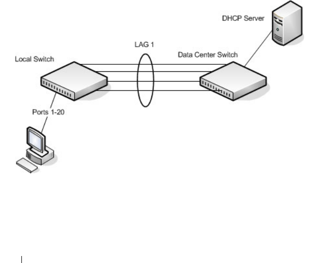
910 Snooping and Inspecting Traffic
Traffic Snooping and Inspection Configuration
Examples
This section contains the following examples:
• Configuring DHCP Snooping
• Configuring IPSG
Configuring DHCP Snooping
In this example, DHCP snooping is enabled on VLAN 100. Ports 1-20
connect end users to the network and are members of VLAN 100. These ports
are configured to limit the maximum number of DHCP packets with a rate
limit of 100 packets per second. LAG 1, which is also a member of VLAN 100
and contains ports 21-24, is the trunk port that connects the switch to the
data center, so it is configured as a trusted port.
Figure 27-25. DHCP Snooping Configuration Topology
The commands in this example also enforce rate limiting and remote storage
of the bindings database. The switch has a limited amount of storage space in
NVRAM and flash memory, so the administrator specifies that the DHCP
snooping bindings database is stored on an external TFTP server.

Snooping and Inspecting Traffic 911
To configure the switch:
1
Enable DHCP snooping on VLAN 100.
console#config
console(config)#ip dhcp snooping vlan 100
2Configure LAG 1, which includes ports 21-24, as a trusted port. All other
interfaces are untrusted by default.
console(config)#interface port-channel 1
console(config-if-Po1)#ip dhcp snooping trust
console(config-if-Po1)#exit
3Enter interface configuration mode for all untrusted interfaces (ports 1-
20) and limit the number of DHCP packets that an interface can receive
to 100 packets per second. LAG 1 is a trusted port and keeps the default
value for rate limiting (unlimited).
console(config)#interface range gi1/0/1-20
console(config-if)#ip dhcp snooping limit rate 100
console(config-if)#exit
4
Specify that the DHCP snooping database is to be stored remotely in a file
called dsDb.txt on a TFTP server with and IP address of 10.131.11.1.
console(config)#ip dhcp snooping database
tftp://10.131.11.1/dsDb.txt
console(config)#exit
5
Enable DHCP snooping for the switch
console(config)#ip dhcp snooping
6
View DHCP snooping information.
console#show ip dhcp snooping
DHCP snooping is Enabled
DHCP snooping source MAC verification is enabled
DHCP snooping is enabled on the following VLANs:
100
Interface Trusted Log Invalid Pkts
----------- ---------- ----------------

912 Snooping and Inspecting Traffic
Configuring IPSG
This example builds on the previous example and uses the same topology
shown in Figure 27-25. In this configuration example, IP source guard is
enabled on ports 1-20. DHCP snooping must also be enabled on these ports.
Additionally, because the ports use IP source guard with source IP and MAC
address filtering, port security must be enabled on the ports as well.
To configure the switch:
1
Enter interface configuration mode for the host ports and enable IPSG.
console(config)#interface range gi1/0/1-20
console(config-if)#ip verify source port-security
2
Enable port security on the ports.
console(config-if)#port security
3
View IPSG information.
console#show ip verify source
--More-- or (q)uit
Interface Filter IP Address MAC Address Vlan
--------- ------- ----------
Gi1/0/1 ip-mac 192.168.3.45 00:1C:23:55:D4:8E 100
Gi1/0/2 ip-mac 192.168.3.40 00:1C:23:12:44:B6 100
Gi1/0/3 ip-mac 192.168.3.33 00:1C:23:AA:B8:01 100
Gi1/0/4 ip-mac 192.168.3.18 00:1C:23:67:D3:CC 100
Gi1/0/5 ip-mac 192.168.3.49 00:1C:23:55:1B:6E 100

Configuring Link Aggregation 913
28
Configuring Link Aggregation
This chapter describes how to create and configure link aggregation groups
(LAGs), which are also known as port-channels.
The topics covered in this chapter include:
• Link Aggregation
• Multi-Switch LAG (MLAG)
Link Aggregation
Overview
Link Aggregation allows one or more full-duplex Ethernet links of the same
speed to be aggregated together to form a LAG. This allows the switch to
treat the LAG as if it is a single link. The Dell Networking series switches
support industry-standard LAGs that adhere to the IEEE 802.3ad
specification.
Assignment of interfaces to dynamic LAGs is based on a maximum of 144
interfaces assigned to dynamic LAGs, a maximum of 72 dynamic LAGs and a
maximum of 8 interfaces per dynamic LAG. For example, 72 LAGs may be
assigned 2 interfaces each, or 18 LAGs may be assigned 8 interfaces each.
Each LAG can consist of up to eight 1 Gbps or eight 10 Gbps ports (or even
eight 40 Gbps interfaces). When eight Gigabit Ethernet ports are configured
as a LAG, the maximum bandwidth for the single, logical interface is 8 Gbps,
and when eight 10 Gbps ports are configured as a LAG, the maximum
bandwidth for the single, logical interface is 80 Gbps.
Figure 28-1 shows an example of a switch in the wiring closet connected to a
switch in the data center by a LAG that consists of four physical 10 Gbps
links. The LAG provides full-duplex bandwidth of 40 Gbps between the two
switches.

914 Configuring Link Aggregation
Figure 28-1. LAG Configuration
LAGs can be configured on stand-alone or stacked switches. In a stack of
switches, the LAG can consist of ports on a single unit or across multiple
stack members. When a LAG members span different units across a stack,
and a unit fails, the remaining LAG members on the functional units
continue to handle traffic for the LAG.
Why Are Link Aggregation Groups Necessary?
The primary purpose of LAGs is to increase the overall bandwidth between
two switches. This is accomplished by effectively aggregating multiple ports
together that act as a single, logical connection between the two switches.
LAGs also provide redundancy. If a link fails, traffic is automatically
redistributed across the remaining links.
What Is the Difference Between Static and Dynamic Link Aggregation?
Link aggregation can be configured as either dynamic or static. Dynamic
configuration is supported using the IEEE 802.3ad standard, which is known
as Link Aggregation Control Protocol (LACP). Static configuration is used
when connecting a Dell Networking N2000, N3000, and N4000 series
switches to an external Gigabit Ethernet switch that does not support LACP.
One advantage of LACP is that the protocol enables the switch to confirm
that the external switch is also configured for link aggregation. When using
static configuration, a cabling or configuration mistake involving the
N2000/N3000/N4000 switch or the external switch could go undetected and
thus cause undesirable network behavior. Both static and dynamic LAGs (via
LACP) can detect physical link failures within the LAG and continue
forwarding traffic through the other connected links within that same LAG.
LACP can also detect switch or port failures that do not result in loss of link.

Configuring Link Aggregation 915
This provides a more resilient LAG. Best practices suggest using dynamic link
aggregation instead of static link aggregation.When a port is added to a LAG
as a static member, it neither transmits nor receives LACP PDUs.
What is LAG Hashing?
Dell Networking series switches support configuration of hashing algorithms
for each LAG interface. The hashing algorithm is used to distribute traffic
load among the physical ports of the LAG while preserving the per-flow
packet order. Enhanced hashing mode is the recommended and default
hashing mode for Dell Networking switches.
The hashing algorithm uses various packet attributes to determine the
outgoing physical port.
The switch supports the following set of packet attributes to be used for hash
computation:
• Source MAC, VLAN, EtherType, and incoming port.
• Destination MAC, VLAN, EtherType, and incoming port.
• Source IP and Source TCP/UDP port numbers.
• Destination IP and Destination TCP/UDP port numbers.
• Source/Destination MAC, VLAN, EtherType, and incoming port.
• Source/Destination IP and Source/Destination TCP/UDP port numbers.
• Enhanced hashing mode
Enhanced hashing mode has following advantages:
• MODULO-N operation based on the number of ports in the LAG.
• Packet attributes selection based on the packet type. For L2 packets,
Source and Destination MAC address plus physical source port are used
for hash computation. For IP packets, Source IP, Destination IP address,
TCP/UDP ports, and physical source port are used.
• Non-Unicast traffic and Unicast traffic is hashed using a common hash
algorithm.
• Excellent load balancing performance.

916 Configuring Link Aggregation
How Do LAGs Interact with Other Features?
From a system perspective, a LAG is treated just as a physical port, with the
same configuration parameters for administrative enable/disable, spanning
tree port priority, path cost as may be for any other physical port.
VLAN
When members are added to a LAG, they are removed from all existing
VLAN membership. When members are removed from a LAG they are added
back to the VLANs that they were previously members of as per the
configuration file. Note that a port’s VLAN membership can still be
configured when it's a member of a LAG. However this configuration is only
actually applied when the port leaves the LAG.
The LAG interface can be a member of a VLAN complying with IEEE
802.1Q.
STP
Spanning tree does not maintain state for members of a LAG, but does
maintain state for the LAG interface. As far as STP is concerned, members of
a LAG do not have individual link state. (Internally, the STP state of the LAG
interface is replicated for the member links.)
When members are deleted from a LAG they become normal links, and
spanning tree maintains their individual link state information.
Statistics
Statistics are collected for LAGs in the same manner as they are collected for
the physical ports, in addition to the statistics collected for individual
members as per the 802.3ad MIB statistics.
LAG Configuration Guidelines
Ports to be aggregated must be configured so that they are compatible with
the link aggregation feature and with the partner switch to which they
connect.
Ports to be added to a LAG must meet the following requirements:
• Interface must be a physical Ethernet link.
• Each member of the LAG must be running at the same speed and must be
in full duplex mode.

Configuring Link Aggregation 917
• The port cannot be a mirrored port
The following are the interface restrictions
• The configured speed of a LAG member cannot be changed.
• An interface can be a member of only one LAG.
Default Link Aggregation Values
The LAGs on the switch are created by default, but no ports are members.
Table 28-1 summarizes the default values for the MAC address table.
Table 28-1. MAC Address Table Defaults
Parameter Default Value
LACP system priority 1
LACP port priority 1
LACP timeout Long
LAG hash algorithm type Enhanced (7)
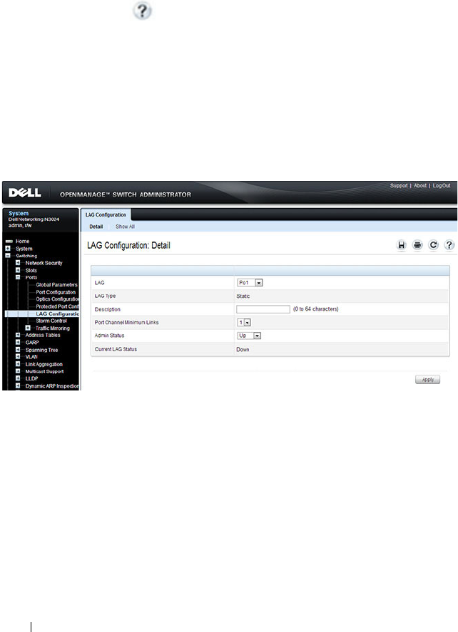
918 Configuring Link Aggregation
Configuring Link Aggregation (Web)
This section provides information about the OpenManage Switch
Administrator pages for configuring and monitoring LAGs on a Dell
Networking N2000, N3000, and N4000 series switches. For details about the
fields on a page, click at the top of the page.
LAG Configuration
Use the LAG Configuration page to set the name and administrative status
(up/down) of a LAG.
To display the LAG Configuration page, click Switching
→
Ports
→
LAG
Configuration in the navigation panel.
Figure 28-2. LAG Configuration
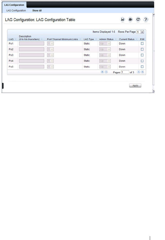
Configuring Link Aggregation 919
To view or edit settings for multiple LAGs, click Show All.
LACP Parameters
Dynamic link aggregation is initiated and maintained by the periodic
exchanges of LACP PDUs. Use the LACP Parameters page to configure
LACP LAGs.
To display the LACP Parameters page, click Switching
→
Link Aggregation
→
LACP Parameters in the navigation panel.
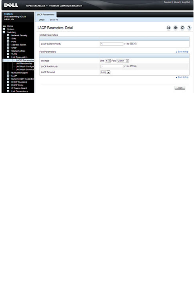
920 Configuring Link Aggregation
Figure 28-3. LACP Parameters
Configuring LACP Parameters for Multiple Ports
To configure LACP settings:
1
Open the
LACP Parameters
page.
2
Click
Show All
.
The
LACP Parameters Table
page displays.
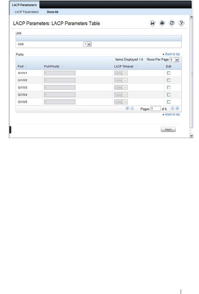
Configuring Link Aggregation 921
Figure 28-4. LACP Parameters Table
3
Select the
Edit
check box associated with each port to configure.
4
Specify the LACP port priority and LACP timeout for each port.
5
Click
Apply
.
LAG Membership
Your switch supports 48 LAGs per system, and eight ports per LAG. Use the
LAG Membership page to assign ports to static and dynamic LAGs.
To display the LAG Membership page, click Switching
→
Link Aggregation
→
LAG Membership in the navigation panel.

922 Configuring Link Aggregation
Figure 28-5. LAG Membership
Adding a Port to a Static LAG
To add a static LAG member:
1
Open the
LAG Membership
page.
2
Click in the
LAG
row to toggle the port to the desired LAG.
The LAG number displays for that port. The LAG number increases each
time you click until the number reaches the maximum LAG number and
then returns to blank (no LAG assigned).
3
Click
Apply
.
The port is assigned to the selected LAG, and the device is updated.
Adding a LAG Port to a Dynamic LAG by Using LACP
To add a dynamic LAG member:
1
Open the
LAG Membership
page.
2
Click in the
LACP
row to toggle the desired LAG port to
L
.
3
Click
Apply
.
The LAG port is added as a dynamic LAG member to the selected LAG.
NOTE: The port must be assigned to a LAG before it can be aggregated to an
LACP.
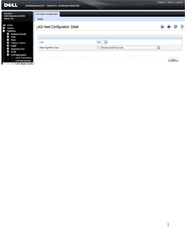
Configuring Link Aggregation 923
LAG Hash Configuration
Use the LAG hash algorithm to set the traffic distribution mode on the LAG.
You can set the hash type for each LAG.
To display the LAG Hash Configuration page, click Switching
→
Link
Aggregation
→
LAG Hash Configuration in the navigation panel.
Figure 28-6. LAG Hash Configuration
LAG Hash Summary
The LAG Hash Summary page lists the channels on the system and their
assigned hash algorithm type.
To display the LAG Hash Summary page, click Switching
→
Link
Aggregation
→
LAG Hash Summary in the navigation panel.
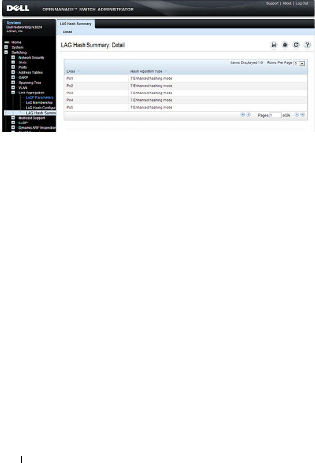
924 Configuring Link Aggregation
Figure 28-7. LAG Hash Summary

Configuring Link Aggregation 925
Configuring Link Aggregation (CLI)
This section provides information about the commands you use to configure
link aggregation settings on the switch. For more information about the
commands, see the
Dell Networking N2000, N3000, and N4000 Series
Switches CLI Reference Guide
at support.dell.com/manuals.
Configuring LAG Characteristics
Beginning in Privileged EXEC mode, use the following commands to
configure a few of the available LAG characteristics. Many of the commands
described in "Configuring Port Characteristics (CLI)" on page 496 are also
applicable to LAGs.
Command Purpose
configure Enter global configuration mode.
interface
interface
Enter interface configuration mode for the specified LAG.
The
interface
variable includes the interface type, which is
port-channel, and the LAG number, for example port-
channel 3.
You can also specify a range of LAGs with the interface
range port-channel command, for example, interface
range port-channel 3-6 configures LAGs 3, 4, 5, and 6.
description
description
Configure a description for the LAG or range of LAGs
port-channel min-links
minimum
Set the minimum number of links that must be up in
order for the port-channel interface to be declared up.
exit Exit to Global Config mode.
CTRL + Z Exit to Privileged EXEC mode.
show interfaces
description port-channel
port-channel number
View the configured description for the specified LAG.
show interfaces port-
channel [
port-channel
number
]
View LAG information for the specified LAG or for all
LAGs.

926 Configuring Link Aggregation
Configuring Link Aggregation Groups
Beginning in Privileged EXEC mode, use the following commands to add
ports as LAG members and to configure the LAG hashing mode.
Command Purpose
configure Enter global configuration mode.
interface
interface
Enter interface configuration mode for the specified port.
The
interface
variable includes the interface type and
number, for example tengigabitethernet 1/0/3.
You can also specify a range of ports with the interface
range command, for example, interface range
tengigabitethernet 1/0/8-12 configures interfaces 8, 9, 10,
11, and 12.
channel-group
port-
channel-number
mode
{on | auto}
Add the port(s) to the LAG specified with the
port-
channel-number
value. Use the auto keyword to add the
port(s) as dynamic members, or use on to specify that the
LAG membership is static.
•
port-channel-number
— Number of a valid port-channel
for the current port to join.
•
on
— Forces the port to join a channel without LACP
(static LAG).
•
active
— Forces the port to join a channel with LACP
(dynamic LAG).
exit Exit to Global Config mode.
interface port-channel
number
Enter interface configuration mode for the specified LAG.
You can also specify a range of LAGs to configure with the
interface range port-channel command, for example,
interface range port-channel 1-3,10 configures LAGs 1, 2,
3, and 10.

Configuring Link Aggregation 927
Configuring LACP Parameters
Beginning in Privileged EXEC mode, use the following commands to
configure system and per-port LACP parameters.
hashing-mode
mode
Set the hashing algorithm on the LAG.
The
mode
value is a number from 1 to 7. The numbers
correspond to the following algorithms:
• 1 — Source MAC, VLAN, EtherType, source module, and
port ID
• 2 — Destination MAC, VLAN, EtherType, source
module, and port ID
• 3 — Source IP and source TCP/UDP port
• 4 — Destination IP and destination TCP/UDP port
• 5 — Source/destination MAC, VLAN, EtherType, and
source MODID/port
• 6 — Source/destination IP and source/destination
TCP/UDP port
• 7 — Enhanced hashing mode
CTRL + Z Exit to Privileged EXEC mode.
show interfaces port-
channel [
port-channel
number
]
View LAG information for the specified LAG or for all
LAGs.
show statistics port-
channel
port-channel-
number
View interface statistics for the specified LAG.
Command Purpose
configure Enter global configuration mode.
lacp system-priority
value
Set the Link Aggregation Control Protocol priority for the
switch. the priority value range is 1–65535.
Command Purpose

928 Configuring Link Aggregation
interface port-channel
number
Enter interface configuration mode for the specified LAG.
You can also specify a range of LAGs to configure with the
interface range port-channel command, for example,
interface range port-channel 1-3,10 configures LAGs 1, 2,
3, and 10.
lacp port-priority
value
Set the Link Aggregation Control Protocol priority for the
port or range of ports. The priority value range is 1–65535.
lacp timeout {long |
short}
Specify whether to wait a long or short time between
LACP PDU transmissions.
exit Exit to Privileged EXEC mode.
show lacp
interface
View LACP parameters for an Ethernet interface or a LAG.
The
interface
parameter includes the interface type
(gigabitethernet, tengigabitethernet, or port-channel)
and number.
Command Purpose

Configuring Link Aggregation 929
Link Aggregation Configuration Examples
This section contains the following examples:
• Configuring Dynamic LAGs
• Configuring Static LAGs
Configuring Dynamic LAGs
The commands in this example show how to configure a static LAG on a
switch. The LAG number is 1, and the member ports are 1, 2, 3, 6, and 7.
To configure the switch:
1
Enter interface configuration mode for the ports that are to be configured
as LAG members.
console(config)#interface range
te1
/0/1-3,
te1
/0/6-7
2
Add the ports to LAG 2 with LACP.
console(config-if)#channel-group 1 mode active
NOTE: The examples in this section show the configuration of only one switch.
Because LAGs involve physical links between two switches, the LAG settings
and member ports must be configured on both switches.

930 Configuring Link Aggregation
3
View information about LAG 1.
console#show interfaces po1
Configuring Static LAGs
The commands in this example show how to configure a static LAG on a
switch. The LAG number is 2, and the member ports are 10, 11, 14, and 17.
To configure the switch:
1
Enter interface configuration mode for the ports that are to be configured
as LAG members.
console(config)#interface range te1/0/10-12,
te1/0/14,te1/0/17
2
Add the ports to LAG 2 without LACP.
console(config-if)#channel-group 2 mode on
Channel Ports Ch-Type Hash Type Min-links Local Prf
------- ------------- ------- --------- --------- ---------
Po1 Active:
Te1/0/1
Inactive:
Te1/0/2,
Te1/0/3,
Te1/0/6,
Te1/0/7
Dynamic 7 1 Disabled
Hash Algorithm Type
1 - Source MAC, VLAN, EtherType, source module and port Id
2 - Destination MAC, VLAN, EtherType, source module and port Id
3 - Source IP and source TCP/UDP port
4 - Destination IP and destination TCP/UDP port
5 - Source/Destination MAC, VLAN, EtherType, source MODID/port
6 - Source/Destination IP and source/destination TCP/UDP port
7 - Enhanced hashing mode

Configuring Link Aggregation 931
3
View information about LAG 2.
console#show interfaces po2
Channel Ports Ch-Type Hash Type Min-links Local Prf
------- ------------- ------- --------- --------- ---------
Po1 Active:
Te1/0/1
Inactive:
Te1/0/2,
Te1/0/3,
Te1/0/6,
Te1/0/7
Static 7 1 Disabled
Hash Algorithm Type
1 - Source MAC, VLAN, EtherType, source module and port Id
2 - Destination MAC, VLAN, EtherType, source module and port Id
3 - Source IP and source TCP/UDP port
4 - Destination IP and destination TCP/UDP port
5 - Source/Destination MAC, VLAN, EtherType, source MODID/port
6 - Source/Destination IP and source/destination TCP/UDP port
7 - Enhanced hashing mode

932 Configuring Link Aggregation
Multi-Switch LAG (MLAG)
Overview
In a typical L2 network, the Spanning Tree Protocol (STP) is deployed to
avoid packet storms due to loops in the network. To perform this function,
STP sets ports into either a forwarding state or a blocking state. Ports in the
blocking state do not carry traffic. In the case of a topology change, STP re-
converges to a new loop-free network and updates the port states. STP is
relatively successful mitigating packet storms in the network, but redundant
links in the network are blocked from carrying traffic by the spanning tree
protocol.
In some network deployments, redundant links between two switches are
bundled together in a Link Aggregation Group (LAG) and appear as a single
link in the spanning tree topology. The advantage is that all LAG member
links can be in the forwarding state and a link failure can be recovered in
milliseconds. This allows the bandwidth on the redundant links to be utilized.
However, LAGs are limited to connecting multiple links between two partner
switches, which leaves the switch as a single point of failure in the topology.
Dell Networking MLAG extends the LAG bandwidth advantage across
multiple Dell Networking switches connected to a LAG partner device. The
LAG partner device is oblivious to the fact that it is connected over a LAG to
two peer Dell Networking switches - instead, the two switches appear as a
single switch to the partner. All links can carry data traffic across a physically
diverse topology and in the case of a link or switch failure, traffic can continue
to flow with minimal disruption.
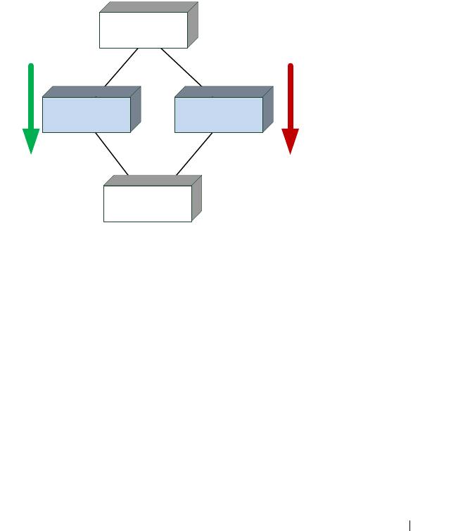
Configuring Link Aggregation 933
Deployment Scenarios
MLAG is intended to support higher bandwidth utilization in scenarios
where a redundant L2 network is desired. In such scenarios the effects of STP
on link utilization are profound. Large percentages of links do not carry data
because they are blocked and only a single path through the network carries
traffic.
Figure 28-8. STP Blocking
MLAG reduces some of the bandwidth shortcomings of STP in an L2
network. It provides a reduced convergence period when a port-channel link
goes down and provides more bandwidth because all links can forward traffic.
In the figure below, if SW1 and SW2 form an MLAG with SW3 and SW4,
none of the links are blocked, which means traffic can flow over both links
from SW4 through to SW1 and SW2 over both links from SW1 and SW2 to
SW3.
×
Traffic does not flow
through SW2 due to
spanning tree blocking
the SW2/SW3 link.
SW4
SW3
SW1 SW2
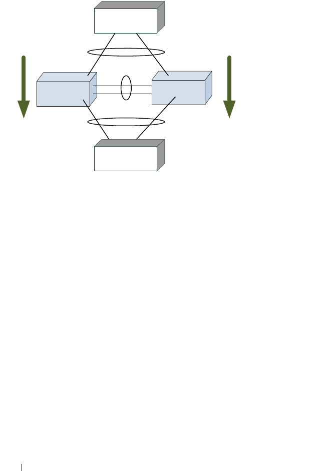
934 Configuring Link Aggregation
Figure 28-9. MLAG in an L2 Network
SW2
SW1
Traffic flows on
all available links.
MLAG
Peer Link
SW4
SW3
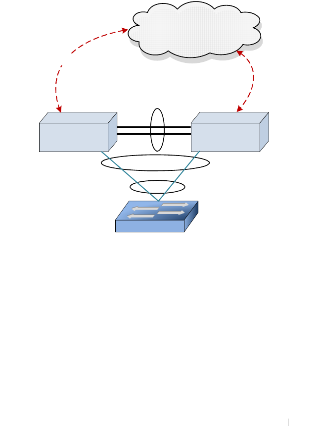
Configuring Link Aggregation 935
Definitions
Refer to Figure 28-10 for the definitions that follow.
Figure 28-10. MLAG Components
MLAG switches: MLAG aware switches running Dell Networking OS switch
firmware. No more than two MLAG aware switches can pair to form one end
of the LAG. Stacked switches do not support MLAGs. In the above figure,
SW1 and SW2 are MLAG peer switches. These two switches form a single
logical end point for the MLAG from the perspective of switch A.
MLAG interfaces: MLAG functionality is a property of port-channels. Port-
channels configured as MLAGs are called MLAG interfaces. Administrators
can configure multiple instances of MLAG interfaces on the peer MLAG
switches. Port-channel limitations and capabilities like min-links and
maximum number of ports supported per LAG also apply to MLAG
interfaces.
SW2SW1
L3 Network
Peer-Link
A
P1
P2
P3
S2
S3
S4
P4
Virtual Link
MLAG
LAG
S1

936 Configuring Link Aggregation
MLAG member ports: Ports on the peer MLAG switches that are part of the
MLAG interface (P1 on SW1 and S1 on SW2).
Non-redundant ports: Ports on either of the peer switches that are not part of
the MLAG (ports P4 and S4). MLAG interfaces and non-redundant ports
cannot be members of the same VLAN, i.e. a VLAN may contain MLAG
interfaces or a VLAN may contain non-redundant ports, but not both.
MLAG peer-link: A link between the two MLAG peer switches (ports
P2,P3,S2,S3). Only one peer-link can be configured per device. The peer-link
is crucial for the operation of the MLAG component. A port-channel must be
configured as the peer-link. All VLANs configured on MLAG interfaces must
be configured on the peer-link as well.
MLAG Dual Control Plane Detection link: A virtual link that is used to
advertise the Dual Control Plane Detection Protocol (DCPDP) packets
between the two MLAG switches (ports P4, S4). DCPDP is optional but
should be used with caution. The protocol is used as a secondary means of
detecting the presence of the peer switch in the network. The DCPDP
protocol must not be configured on MLAG interfaces.
Configuration Consistency
The administrator must ensure that the neighboring devices connected to
MLAG switches perceive the two switches as a single spanning tree and Link
Aggregation Control Protocol (LACP) entity. To achieve this end, the
following configuration settings must be identical for MLAG links on the
MLAG peer switches:
1
Link aggregation
– Hashing mode
– Minimum links
– Static/dynamic LAG
– LACP parameters
• Actor parameters
•Admin key
• Collector max-delay
• Partner parameters

Configuring Link Aggregation 937
2
STP
The default STP mode for Dell Networking switches is RSTP. VLANs
cannot be configured to contain both MLAG ports and non-MLAG (non-
redundant) ports. Only RSTP or MSTP are supported with MLAG. STP-
PV and RSTP-PV are not supported with MLAG. The following STP
configuration parameters must be the identical on both MLAG peers.
– Spanning-tree version (RSTP or MSTP)
– Bpdufilter
– Bpduflood
–Auto-edge
–TCN-guard
–Cost
–Edgeport
–STP Version
– STP MST VLAN configuration
– STP MST instance configuration (MST instance ID/port priority/port
cost/mode)
– Root guard
–Loop guard
3
Port-channel interface
The following port-channel attributes must be identical for MLAG port-
channels:
– Port-channel mode
– Link speed
–Duplex mode
–MTU
–Bandwidth
– VLAN configuration

938 Configuring Link Aggregation
The administrator should also ensure that the following are identical
before enabling MLAG:
–FDB entry aging timers
– Static MAC entries.
– ACL configuration
4
Interface Configuration
– PFC configuration
– CoS queue assignments
5
VLAN configuration
– MLAG VLANs must span the MLAG topology and be configured on
both MLAG peers. This means that every MLAG VLAN must connect
to two partner LAGs.
– VLAN termination of an MLAG VLAN on an MLAG peer is not
supported.
6
Switch firmware versions
Except during firmware upgrade, the peer switch firmware versions must
be identical, as subtle differences between versions may cause instability.
The administrator must ensure that the above configuration items are
configured identically on the MLAG interfaces on both of the MLAG peers
before enabling the MLAG feature. If the configuration settings are not in
sync, the MLAG behavior is undefined. Once the above configuration is in
place and consistent, the two switches will form an MLAG that operates in
the desired manner. The MLAG may form even if the configuration is not
consistent, however, it may not operate consistently in all situations.

Configuring Link Aggregation 939
Operation in the Network
Below is a sample MLAG topology and discussion:
Figure 28-11. Example MLAG Topology
In Figure 28-11:
1
VLAN 10 spans the MLAG network.
2
P and S are MLAG-aware peer devices. P stands for primary and S stands
for secondary. The roles are elected after the DUTs exchange keep-alive
messages. The two devices are connected with a peer-link {P3/P4–S3/S4}.
Ports P1, S1 are members of MLAG1 and ports P2, S2 are members of
MLAG2.
3
A port-channel must be configured as the peer-link. In
Figure 28-11,
P3,
P4 and S3, S4 are the port-channel ports that form the peer-link.
4
MLAG devices select the roles based on keep-alive messages that run over
the peer-link.
5
A, B, and C are MLAG-unaware devices.
6
A, B, and C are partner devices that form an MLAG with P and S. On A, B,
and C, the aggregation is a regular LAG.
7
MLAG links are shown in blue.
PS
P1
P3,P4 S3,S4
S5
P5
S1 S2P2
Peer-Link
A B
MLAG 1 MLAG 2
C
C1 C2
MLAG3 VLAN 10

940 Configuring Link Aggregation
Supported topologies and the way traffic is handled in these topologies is
explained in the following sections.
The MLAG component uses the keep-alive protocol to select a primary and a
secondary device. The primary switch owns the MLAG member ports on the
secondary device. It handles the control plane functionality of supported
protocols for the MLAG member ports on the secondary.
Peer-Link
The peer-link is a crucial for MLAG operation. The peer-link must be
configured on a port-channel interface. Only one peer-link aggregation group
is allowed per peer switch and this peer-link is shared by all instances of
MLAG running on the two peer switches. The peer-link must NOT have
spanning tree enabled.
The peer-link is used for the following purposes:
• To transport keep-alive messages to the peer.
• To sync FDB entries learned on MLAG interfaces between the two MLAG
peer switches.
• To forward STP BPDUs and LACPDUs received on secondary MLAG
member ports to the primary MLAG switch.
• To send interface events related to MLAG interface and member ports
that occur on the secondary switch to the primary switch.
• To transfer MLAG control information between the primary and
secondary MLAG switches.
• Support a redundant forwarding plane in the case that all member ports of
an MLAG interface are down on an MLAG peer. In this case, traffic
received on the peer switch destined to the MLAG peer with the downed
ports is sent over the peer-link to the peer MLAG switch for forwarding to
the partner switch.
The peer-link is not utilized for partner traffic unless all LAG links connected
to an MLAG partner on a single MLAG peer are disrupted. It is strongly
recommended that the MLAG peer LAG consist of multiple physical links
with sufficient bandwidth to carry all traffic expected to be carried by either
of the MLAG peers.

Configuring Link Aggregation 941
The MLAG component internally configures filters so that traffic ingressing a
peer-link is blocked from egress on the peer MLAG switch. The filters are
modified when there is a failure of all the MLAG member interfaces on an
MLAG switch and traffic must egress through selected ports on the MLAG
peer. These filters block incoming traffic on all VLANs configured on the peer
link, not just those configured as part of an MLAG. Therefore, there is no
connectivity between non-redundant ports across the peer-link.
Control Plane Election in MLAG Switches
The MLAG component uses the keep-alive protocol to select a primary and a
secondary switch. The keep-alive protocol is mandatory. The selection of the
primary switch is non-preemptive and is not configurable.
Once elected, the primary switch owns the MLAG member ports on the
secondary device. It handles the control plane functionality of supported
protocols for the MLAG member ports on the secondary switch. Protocol
status is not sent from the primary to the secondary switch. Always use the
management interface on the primary switch to examine MLAG status.
Peer-Link Keep-alive Protocol
MLAG peers exchange keep-alive packets over the peer-link. The keep-alive
protocol is L2-based. Keep-alive messages are used for electing roles and to
inform the MLAG peer that the MLAG switch is alive and functioning
properly. The keep-alive protocol sends messages with an Ether-type of
0x88E8 addressed to destination MAC 01:00:B5:00:00:00.
Dual Control Plane Detection Protocol
The MLAG component may optionally run the Dual Control Plane
Detection Protocol (DCPDP) to detect the presence of the peer switch
independently of the keep-alive protocol running on the peer link.
The Dual Control Plane Detection Protocol is a UDP-based L3 protocol.
DCPDP may be configured on a routed VLAN that does not contain any
MLAG port-channel interfaces. When enabled, the DCPDP sends an L3
control plane detection message to the peer once every second. The message
is unidirectional and contains the senders MAC address in the payload. The
state of the primary and secondary MLAG switches is maintained on both
MLAG peers.
DCPDP runs over an IP interface when enabled.

942 Configuring Link Aggregation
DCPDP and Peer Link Failures
DCPDP is intended to provide a secondary layer of protection against peer
link failures. If the peer-link goes down but the DCPDP protocol is enabled
and remains up, the MLAG links on the MLAG secondary peer are disabled.
If the peer-link is restored, a new primary switch is elected, the primary switch
assumes control over the secondary peer, and the MLAG links are brought up.
In the case where there are no keep-alive messages detected from the peer and
DCPDP is disabled, but both peer units remain up, two primary switches
result, each with a unique MAC address, and each operating over its part of
the former MLAG. In this situation, the selection of dynamic or static LAGs
determines the MLAG behavior.
On a peer-link failure with DCPDP disabled and the MLAG configured with
dynamic LAGs to the partners, traffic forwarding continues through the
primary MLAG switch. LACP running on the partner device detects that the
port-channel connected to the secondary MLAG switch is sending LACPDUs
with a different system ID and brings down the links connected to secondary
MLAG peer. This behavior reduces or eliminates spanning tree reconvergence
due to the MLAG switches sending BPDUs with different bridge IDs to the
partner switch.
On a peer-link failure with DCPDP disabled and the MLAG configured with
static LAGs to the partners, traffic forwarding continues through both the
primary and secondary MLAG switches. Spanning tree sends BPDUs with
different bridge IDs to the partner switch, resulting in serial spanning tree
reconvergence. For this reason, dynamic MLAGs are strongly recommended.
L2 Configuration Steps
This section describes how to configure two MLAG peers in a basic L2
switching configuration with the default spanning-tree configuration.
1
Enable MLAG globally and create the MLAG VLANs:
feature vpc
vlan 10-17
exit
2
Configure the keep-alive protocol:
a
Configure the device priority using the
role
command, if desired. This
should be configured differently for each of the MLAG peers.

Configuring Link Aggregation 943
b
Configure the timeout interval, if desired.
vpc domain 1
role 10
exit
Modifications to priority and timeout interval are effective only before the
keep-alive protocol is enabled. Once enabled, MLAG switches contest in
an election to select the primary and secondary switch. The election is
non-preemptive.
3
Configure the peer-link. On each MLAG peer:
• Configure a port-channel as the peer-link for the MLAG devices. It is
recommended that the administrator use dynamic LAGs as port-
channels.
• It is strongly recommended that the MLAG peer LAG consist of
multiple physical links with sufficient bandwidth to carry all MLAG
traffic expected to be carried by either MLAG peer.
• Disable spanning tree on the peer-link.
• Enable trunking on the peer-link. Remove any non-MLAG VLANs
from the peer-link trunk port. VLANs cannot be configured to contain
both MLAG ports and non-MLAG (non-redundant) ports.
• Ensure that the peer-link has a native VLAN configured.
• Optionally, configure UDLD on the peer-link to detect and shut down
unidirectional links.
• Associate the port-channel with physical links.
interface port-channel 1
description "MLAG-Peer-Link"
spanning-tree disable
switchport mode trunk
vpc peer-link
exit
interface range te1/0/1-2
channel-group 1 mode active
description "MLAG-Peer-Link"
udld enable
udld port aggressive
exit

944 Configuring Link Aggregation
When the peer-link is configured, the MLAG component disables learning
on the port-channel configured as the peer-link.
4
Configure
DCPDP
(optional):
a
Configure a VLAN routing interface and assign a local IP address
(different from the peer address).
b
Configure the peer-switch IP address (the destination IP address)
c
If needed, configure the UDP port number to send and receive the
protocol messages.
d
Configure the source IP address
e
Enable the protocol. The protocol starts running if MLAG is globally
enabled.
vlan 100
interface vlan 100
ip address 192.168.0.2 255.255.255.0
exit
vpc domain 1
peer-keepalive destination 192.168.0.1 source 192.168.0.2
peer detection enable
exit
5
Configure the MLAG partner interfaces:
Configure a port-channel as an MLAG interface and assign to a VPC. Each
MLAG must have a unique VPC ID and the VPC configuration must be
identical on both switches. The port-channels on the MLAG peer must be
assigned to the same VPC ID. However, the member ports for the port-
channel may be different. The administrator must ensure that the port-
channel configuration on both the switches is in sync before enabling
MLAG. After the MLAG interfaces are enabled, the MLAG interfaces are
operationally disabled for a brief period while the MLAG component
exchanges information regarding the port members that constitute the
port-channel on each device. Once this information is populated on both
devices, the MLAG interfaces are operationally enabled and traffic
forwarding on MLAG interfaces is allowed.
The secondary switch forwards all BPDUs/LACPDUs received on the port
members of the MLAG interface to the primary switch over the peer-link.
Events related to MLAG interface and their port members are forwarded

Configuring Link Aggregation 945
to the primary switch for handling. FDB entries learned on MLAG
interfaces are synced between the two devices.
interface range gi1/0/1-4
channel-group 2 mode active
exit
interface range gi1/0/5-8
channel-group 3 mode active
exit
interface port-channel 2
switchport mode trunk
vpc 1
exit
interface port-channel 3
switchport mode trunk
vpc 2
exit
Switch Firmware Upgrade Procedure
MLAG supports minimally intrusive firmware upgrade of the MLAG peer
switches. In most cases, protocols with retransmission capability, e.g., TCP,
will experience a limited interruption of service. Network operators must
ensure that the aggregate bandwidth in use on the MLAG can be supported
on a single MLAG peer.
Use the show vpc brief command to determine which switch is the primary
switch. This procedure upgrades the standby switch first, followed by the
primary switch. Following this order reduces the reconvergence time to the
minimum.
Upgrade Steps
Disable DCPDP if enabled:
1
On the secondary switch, disable DCPDP if enabled and save the
configuration.
2
On the primary switch, disable DCPDP if enabled and save the
configuration.
Upgrade the MLAG standby switch:
1
On the MLAG standby switch, shut down the MLAG-enabled physical
links (not the port-channel).

946 Configuring Link Aggregation
2
On the MLAG standby switch, shut down the MLAG peer-link.
3
Copy the new firmware to the standby switch, activate it, and reboot the
switch.
4
Re-enable the peer-link, if disabled, and ensure that it is up. Re-enable the
MLAG-associated physical ports.
5
Wait until traffic is re-established on the standby switch.
Repeat the upgrade procedure on the MLAG primary peer:
1
On MLAG primary switch, shut down the MLAG enabled physical links.
2
On MLAG primary switch, shut down the MLAG peer-link.
3
Copy the new firmware to the primary switch, activate it, and reboot the
switch.
4
Re-enable the peer link, if disabled, and ensure that it is up. Re-enable the
MLAG-associated physical ports.
5
Verify that traffic is re-established on the primary switch after the
reconvergence.
At this point, the switch firmware is upgraded and the MLAG is fully
functional.
Static Routing on MLAG Interfaces
MLAG interfaces can be enabled as L3 VLANs; that is, they can be assigned
IP addresses. Static inter-VLAN routing is NOT supported on MLAG VLANs
on the MLAG peers, and every MLAG VLAN must terminate on two MLAG
partners. There is no support for routing protocols such as OSPF, RIP, etc. on
MLAG interfaces. VRRP can be configured on these routing interfaces to
provide Virtual IP/Virtual MAC redundancy. Routing is supported only on the
edge of the MLAG towards the partner network, in support of implementing
a subnet per VLAN towards which the partner network can route. The interior
MLAG VLANs, and especially the MLAG peer links, must be configured for
switching and must span the MLAG topology.
MLAGs and Routing
MLAG is supported as a replacement for spanning tree in L2 switched
network topologies. When connecting to routed networks, the links/VLANs
on the router must be part of the MLAG domain, and the links/VLANs
leading to the rest of the L2 network or to L3 hosts must be part of the
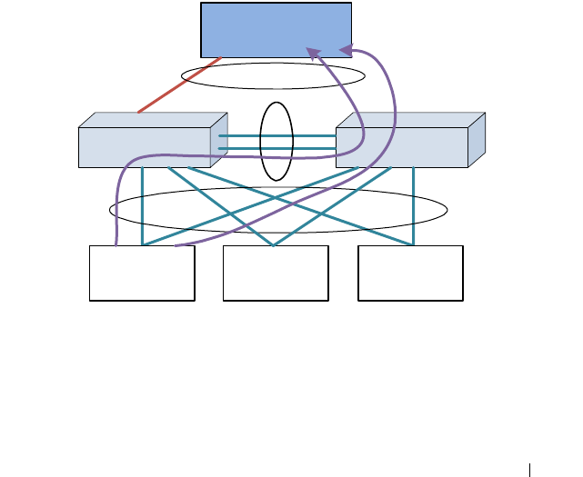
Configuring Link Aggregation 947
MLAG domain for the MLAG feature to automatically utilize the peer-link to
forward packets around failures. MLAG VLANs may have IP addresses
assigned, but MLAG VLANs cannot be used to route across MLAG or non-
redundant VLANs, as the MLAG feature does not correlate failures in one
VLAN with another VLAN to unblock packets crossing the MLAG peer-link.
Recommended L3 Connectivity
The topology shown in Figure 28-12 uses the MLAG switches as L2 switches.
All VLANs traverse the MLAG topology from the top switches/routers to the
bottom switches/routers. The LAGs for each VLAN host are in a separate
VPC. The router sees the port-channel as a single logical interface with
multiple VLANs. This topology is highly recommended as it utilizes MLAG
in the scenario for which it was intended (redundant full-bandwidth
replacement for spanning tree) and allows the MLAG peers to detect failures
and unblock the appropriate VLANs on the peer link so that traffic flow can
continue unimpeded.
Figure 28-12. Recommended L3 Connectivity
MLAG Router PeerMLAG Router Peer
Peer-Link
VLAN 10
Host
MLAGs
L3 Router
MLAG VLAN 10, 20, 30
Failed Link
VLAN 20
Host
VLAN 30
Host
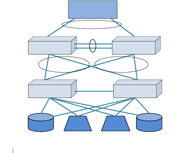
948 Configuring Link Aggregation
Alternative Recommended L3 Connectivity
The loop-free topology shown in Figure 28-13 uses the MLAG switches as L2
switches in an EOR role. The single VLAN traverses the MLAG topology
from the top router to the bottom storage and servers. Multiple VLANs in
different VPCs may be used to isolate clusters of storage/servers from each
other. This topology is highly recommended, as it utilizes MLAG in the
scenario for which it was intended (redundant full-bandwidth replacement
for spanning tree in a fully L2 topology) and allows the MLAG peers to detect
failures and unblock the appropriate VLANs on the peer link so that traffic
flow can continue unimpeded.
The lower pair of switches connects clusters of storage and servers in a TOR
role in support of devices that do not support link aggregation. Switching
between the storage and the servers within the rack proceeds in the normal
manner and remains isolated on the lower switch pair that is not part of the
MLAG domain. Traffic entering or exiting the rack proceeds over the EOR
MLAG.
Figure 28-13. Alternative Recommended L3 Connectivity
MLAG Peer SwitchMLAG Peer Switch
MLAG
Router
MLAG
MLAG
Switch (not part of
MLAG domain)
Switch (not part of
MLAG domain)
Storage Server Storage
Server
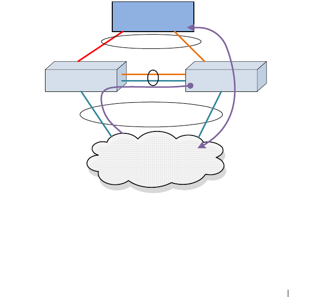
Configuring Link Aggregation 949
L3 VLAN Termination on MLAG Not Supported
In the “two-armed” fully routed scenario shown in Figure 28-14, both the
routed network and the switched network are in the MLAG. Switched traffic
to and from the upstream network is automatically unblocked over the peer-
link when an MLAG link fails. But, because the failed link is part of an L3
port-channel (with a unique VLAN), the peer-link does not automatically
unblock the downstream routed VLANs (which are not correlated with the
upstream MLAG VLANs) across the peer link. Specifically, MLAG does not
correlate the failure in VLAN 30 with VLAN 20. This leads to a black hole.
Adding a backup routed link solves the black hole issue, but it also makes the
MLAG solution unnecessary. L3-routed VLAN termination on the MLAG
peers is not supported—VLANs must extend across the MLAG peers to two
MLAG partners.
Figure 28-14. L3 VLAN Termination on MLAG, Example 1
MLAG Router PeerMLAG Router Peer
Peer-Link
MLAG
Router
MLAG VLAN 30
Failed Link
Switched Network
Only
VLAN 20

950 Configuring Link Aggregation
In the scenario shown in Figure 28-15(similar to the previous scenario), the
downstream router is not configured with port-channel and uses ECMP or
some other load sharing scheme to send packets to routed MLAG peers.
MLAG cannot react appropriately to a link failure on the upstream router
because the VLANs are routed across the MLAG peers. MLAG cannot
logically connect the failure on VLAN 30 with orphan VLAN 20.
Consequently, MLAG does not unblock VLAN 20 from traversing the peer
link. The downstream router continues to send packets on VLAN 20 to the
MLAG peer with the failed link. But because routed VLAN 20 is not part of
the MLAG, packets remain blocked when transiting the MLAG peer link. L3
routed VLANs termination on the MLAG peers is not supported—VLANs
must extend across the MLAG peers.
Figure 28-15. L3 VLAN Termination on MLAG, Example 2
Degenerate Routing Topology
In a “one-armed” topology, the MLAG is partnered with a single router or
switch. The router is configured with a LAG toward the MLAG peer switches
and has an IP address configured on the router LAG. The peer switches may
be configured with VRRP and have IP addresses assigned to both the routed
VLANs. If a multi-tier MLAG topology is used below the MLAG peers, these
switches must not have L3 port-channels configured as part of the MLAG. An
additional backup routed link between the MLAG peers is required to handle
MLAG Router PeerMLAG Router Peer
Peer-Link
Router
MLAG VLAN 30
Failed Link
VLAN 20
Router
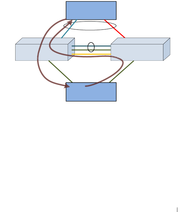
Configuring Link Aggregation 951
the case where a link from the router to one of the MLAG peers fails. Static
routes must be added to the primary and secondary MLAG peers to route
traffic addressed to the connected router across the backup routed link in the
case of a failure of an MLAG link to the router.
This is not a recommended topology, as the same scenario can be achieved
without the use of MLAG by simply configuring the middle switches as
routers and using ECMP to load-balance across the links to the redundant
router pair. In this type of solution, MLAG adds no value, as the redundancy
is provided by L3 routing, not by the MLAG.
Figure 28-16. Degenerate Routing Topology
In the one-armed scenario in Figure 28-16, the MLAG cannot associate the
failure of the VLAN 30 link with VLAN 20. Traffic from the routed or
switched network towards the upstream router is routed over the backup
router link when the MLAG link fails solely based on the routing
configuration. Traffic from the upstream router on VLAN 30 to the
switched/routed network is handled by the MLAG failover scenario and is
switched across the peer-link on VLAN 30, but it could just as easily be
handled by L3 routing.
Peer-Link
Router
MLAG
VLAN 30
VLAN 20
Router or Switch
VLAN 30
IP address 192.168.30.1/24
Failed Link
VLAN 10
IP address 192.168.10.1/24
IP route 192.168.30.1 192.168.20.1 200
VLAN 10
IP address 192.168.10.2/24
IP route 192.168.30.1 192.168.10.1 200
VLAN 20
1
6
8
I
P
r
o
u
t
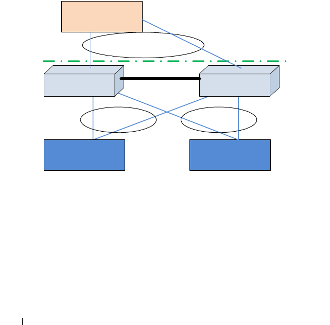
952 Configuring Link Aggregation
Virtual Router Redundancy Protocol
If VRRP is enabled on a VLAN that has an MLAG port as its member, both
VRRP routers become VRRP masters operationally in the VLAN. This is to
allow load balancing of the northbound L3 traffic on the MLAG.
Since the peer-link is a member of the same routing VLANs as all MLAGs,
both the primary and secondary MLAG routers see VRRP advertisements
sent by the other router. The internal switch packet filters are modified to
drop VRRP advertisement packets if they are received on a VLAN that has an
MLAG as its member. This ensures that both MLAG devices become VRRP
Masters.
Consider the scenario in Figure 28-17.
Figure 28-17. MLAG with VRRP
When L3 data is received by the MLAG primary switch destined to A, P
would trigger an ARP request to learn A's MAC address. In this case, the ARP
request originated by P would have its interface MAC address as the source
MAC address (MAC-P, for example) and interface IP address as the source IP
address. If the ARP reply from A, with destination MAC address as MAC-P, is
hashed to S, the packet will be forwarded by S to P over the peer-link so that P
can learn A's MAC address. This requires that the virtual IP address of the
VRRP “routers” be different from the physical IP of either of the MLAG
peers. This is to ensure that packets generated by either of the MLAG peers is
S2
A B
R1
P S

Configuring Link Aggregation 953
transmitted with the source MAC address as the physical MAC address and
not the virtual MAC address. In the example in Figure 28-17, if the virtual
MAC address is used as the source MAC address in the ARP from P to A, then
S will consume the packet, as it is operationally a VRRP master too. The
packet is forwarded to P if the physical MAC address is used.
Note that the VLANs connecting A and B to the MLAG peers are extended to
R1. P and S do not actually route packets. Within the MLAG domain, packets
are switched only.
Caveats and Limitations
Traffic to and from non-redundant ports is filtered and never crosses the
MLAG peer-link, and such ports/VLANs need to obtain connectivity via an
alternative other than the MLAG-connected ports/VLANs.
Port-channel numbers within a VPC must be identical.
MLAG non-redundant ports do not run spanning tree and should be used and
connected with caution. It is recommended that these ports be configured
and used as routing interfaces on point-to-point links and only configured
with VLANs that are not part of the MLAG domain.
MLAG peer switches must be the same model and have the same port count
and module occupancy (if modules are used in the MLAG domain).
Specifically, a port referred to on the secondary must be present on the master
to be accepted for configuration. This is due to the table sizes (ARP, FDB,
etc.), where the primary switch may learn more MAC addresses than the
secondary switch and then, upon failover, the secondary will not be able to
forward traffic to all of the addresses supported by the primary switch. It is a
requirement of a port-channel that the link members operate at the same
duplex and speed settings. In addition, copper ports have larger latencies than
fiber ports. If fiber and copper ports are aggregated together, packets sent over
the fiber ports would arrive significantly sooner at the destination than
packets sent over the copper ports. This can cause significant issues in the
receiving device, as it would be required to buffer a potentially large number
of frames. Devices unable to buffer the requisite number of frames will show
excessive frame discard.
Routing is not supported across multiple MLAGs (i.e., in two-tier topology).
This is a fundamental limitation of MLAG, which is intended as a
replacement for other, less efficient L2 topologies. Should a multitier L3
topology be desired, other well established and well understood techniques,

954 Configuring Link Aggregation
such as ECMP and redundant router pairs, will allow a L3 routed network to
utilize bandwidth efficiently. L3 routing is capable of routing packets around
failed links and failed routers.
Spanning tree (and LACP) PDUs are proxied from the secondary MLAG peer
to the MLAG primary switch. This implies that at least two spanning tree
roots will exist in the MLAG network. Spanning tree on the secondary switch
shows as the root bridge because, in a properly configured network, it will
have no ports attached. In an improperly configured network, one in which
orphan ports and orphan port VLANs are configured on one or both MLAG
switches, three root bridges may appear in the network: the root bridge for the
MLAG member ports/VLANs on the primary switch, the port-less root bridge
on the secondary switch, and the root bridge for the orphan ports/VLANs that
are not part of the MLAG. Careful planning may be required when
configuring the network to ensure that orphan ports are isolated on the
MLAG peers, and segregating the MLAG VLANs from the non-MLAG
VLANs to not cross the peer link can reduce the number of root bridges in the
network to two.
The peer link requires a native VLAN to be configured. This is a limitation of
the peer-link keep alive protocol.
On primary switch failover, the secondary switch flushes the FDB MAC
addresses and uses its own MAC address in spanning tree BPDUs and in the
LACP actor ID. This will cause LACP to rebuild the link aggregation group
followed by spanning tree reconvergence.
MLAG-supported protocols are active only on the MLAG primary switch.
The protocols are proxied from the secondary peer switch to the primary
switch. The primary switch receives state information from the secondary
peer switch and programs the secondary peer hardware. It does not send
protocol state information to the secondary peer. This leads to a number of
seemingly inconsistent behaviors if these facts are ignored:
• MLAG port-channel state is maintained on the primary peer only. The
MLAG secondary peer has accurate state for the member links, but not for
an MLAG port-channel. The operator can shut down a MLAG port-
channel only from the primary MLAG peer.
• Shutting down a MLAG port-channel on the primary peer shuts down the
port-channel on both the primary and secondary MLAG peers.

Configuring Link Aggregation 955
• Shutting down a MLAG port-channel on the secondary MLAG peer has no
effect. The operator can shut down the individual links instead.
• The spanning tree status is only shown correctly on the primary MLAG
peer.
• The secondary switch shows the spanning tree status as root. This is
because there are no ports belonging to spanning tree on the secondary
switch. MLAG ports on the secondary switch belong to the spanning tree
running on the primary switch.
• On a failover from the primary MLAG peer to the secondary MLAG peer,
the ports are made members of the secondary MLAG peer switch's
spanning tree and spanning tree reconvergence occurs. The forwarding
database and ARP cache are flushed and relearned.
• MLAG (VPC) status only shows correctly on the primary MLAG peer and
does not show correctly on the secondary MLAG peer. Status is not
forwarded from the primary MLAG peer to the secondary MLAG peer.
The Dell Networking MLAG solution is not peer-compatible with other
vendor's multichassis LAG solutions. Dell Networking switches configured for
MLAG cannot peer with another vendor switch.
IGMP snooping is not supported on MLAG-enabled switches. Disable IGMP
snooping before enabling MLAG.
MLAG interfaces and non-redundant ports cannot be members of the same
VLAN; i.e., a VLAN may contain MLAG interfaces or a VLAN may contain
non-redundant ports, but not both.
The Dell Networking MLAG solution supports MSTP and RSTP spanning
tree modes only. Spanning tree may also be disabled on the MLAG peers.
STP-PV and RSTP-PV are not supported in the MLAG solution.
Only two switches are supported as MLAG peers. These switches may not be
stacked with other switches.
The MLAG peer switches synchronize the state of spanning tree, the L2
forwarding cache, and other protocols to support reduced convergence times
during MLAG link and MLAG switch failures. The synchronized state is only
available on the MLAG primary switch. Table 28-1 indicates which switch
features synchronize their state across the MLAG peers.

956 Configuring Link Aggregation
• An N/A entry indicates that state synchronization is not required (usually
for a link local protocol) and the feature can be configured on an MLAG
VLAN or MLAG-associated links. In some cases, it may be necessary to
configure an N/A feature identically on the MLAG peer switches for it to
work properly; e.g., port mirroring for an MLAG link must be configured
on both MLAG peer switches to capture the conversation from the MLAG
partner switch.
• A Yes entry indicates that the feature may be configured on an MLAG
VLAN and will synchronize state across the MLAG peers. The
configuration for features marked Yes must be identical on both switches.
MLAG does not synchronize configuration with the MLAG peer.
• A No entry indicates that the switch feature does not synchronize state
across the MLAG peers and the feature may not be configured on an
MLAG VLAN.
Table 28-2. MLAG State Synchronization Per Feature
Components MLAG State Synchronization Support
DOT1Q Yes
Protocol Based VLANs/802.1v No
GARP No
GVRP No
GMRP No
DOT1P No
Unauthenticated VLAN No
Voice VLAN No
Guest VLAN No
MAC Authentication Bypass No
Broadcast Storm Recovery No
DOT3AD Yes
LAG Hashing Yes
Port Mirroring N/A
MAC Filter N/A

Configuring Link Aggregation 957
MFDB No
IGMP/MLD Snooping No
DOT1Qbb No
DOT1S Yes
Loop Guard No
FDB Yes
MACLOCK No
DVLAN No
DOT1AB No
IP Subnet-based VLANs N/A
MACVLAN N/A
Protected Port No
DHCP Snooping No
IP Source Guard No
Dynamic ARP Inspection No
Auto-Negotiation N/A
L2-Relay No
MRP No
MMRP No
DOT1AS No
802.1qav No
DOT1AG No
ACL N/A
DiffServ N/A
COS N/A
ACL Logging N/A
Flow-based port mirroring N/A
Table 28-2. MLAG State Synchronization Per Feature (Continued)
Components MLAG State Synchronization Support

958 Configuring Link Aggregation
VOIP No
iSCSI No
DOT1AD No
DOT3AH No
DCBX N/A
ETS N/A
FIP Snooping No
MVRP No
Management ACL No
UDLD N/A
Private VLAN No
LLPF No
Port Aggregator No
EAV No
MSRP No
MVR No
Class-Based VLAN No
DHCP Filtering No
EASY_ACL No
Media VLAN No
PBVLAN No
VLAN-Rate Limit No
Flow Control N/A
LLDP N/A
Jumbo Frames N/A
Table 28-2. MLAG State Synchronization Per Feature (Continued)
Components MLAG State Synchronization Support

Configuring Link Aggregation 959
Basic Configuration Example
This example shows the configuration of the two MLAG peers and a single
MLAG partner in the simplest possible configuration. No MLAG peer
priorities are configured, nor is UDLD enabled on the peer-link. DCPDP is
not enabled. The default spanning tree configuration is used and spanning-
tree is disabled on the peer link.
MLAG Peer A
!Current Configuration:
!System Description "Dell Networking N3024F, 6.0.0.0, Linux 3.6.5-
858bcf6e"
!System Software Version 6.0.0.0
!
configure
vlan 10
exit
hostname "MLAG-Peer-A"
slot 1/0 2 ! Dell Networking N3024F
stack
member 1 2 ! N3024F
exit
!
interface Gi1/0/23
channel-group 2 mode active
description "MLAG-Partner-Link"
exit
!
interface Te1/0/1
channel-group 1 mode active
description "MLAG-Peer-Link"
exit
!
interface port-channel 1
description "MLAG-Peer-Link"
spanning-tree disable
switchport mode trunk
vpc peer-link
exit
!
interface port-channel 2
switchport mode trunk
switchport trunk native vlan 10
vpc 1

960 Configuring Link Aggregation
exit
snmp-server engineid local 800002a203001ec9dec52b
snmp-server agent boot count 2
feature vpc
vpc domain 1
peer-keepalive enable
exit
exit
MLAG Peer B
!Current Configuration:
!System Description "Dell Networking N3024F, 6.0.0.0, Linux 3.6.5-
858bcf6e"
!System Software Version 6.0.0.0
!
configure
vlan 10
exit
hostname "MLAG-Peer-B"
slot 1/0 2 ! Dell Networking N3024F
stack
member 1 2 ! N3024F
exit
!
interface Gi1/0/23
channel-group 2 mode active
description "MLAG-Partner-Link"
exit
!
interface Te1/0/1
channel-group 1 mode active
description "MLAG-Peer-Link"
exit
!
interface port-channel 1
description "MLAG-Peer-Link"
spanning-tree disable
switchport mode trunk
vpc peer-link
exit
!
interface port-channel 2
switchport mode trunk
switchport trunk native vlan 10

Configuring Link Aggregation 961
vpc 1
exit
snmp-server engineid local 800002a203001ec9dec513
snmp-server agent boot count 3
feature vpc
vpc domain 1
peer-keepalive enable
exit
exit
MLAG Partner
!Current Configuration:
!System Description "Dell Networking N2048, 6.0.0.0, Linux 3.6.5-
858bcf6e"
!System Software Version 6.0.0.0
!
configure
hostname "LAG-SW"
slot 1/0 5 ! Dell Networking N2048
stack
member 1 8 ! N2048
exit
interface vlan 1
ip address dhcp
exit
!
interface Gi1/0/1
channel-group 1 mode active
exit
!
interface Gi1/0/2
channel-group 1 mode active
exit
!
interface port-channel 1
switchport mode trunk
exit
snmp-server engineid local 800002a203001ec9deb777
snmp-server agent boot count 3
exit

962 Configuring Link Aggregation
Status Reporting
The status outputs of the various VPC commands are self-explanatory. Both
the configured and operational status is shown in the outputs. Additional
commands are shown below that may be useful in troubleshooting MLAG
configuration or operational issues. All of the commands below are run on the
MLAG primary switch except as noted otherwise.
MLAG-Peer-A(config)#show vpc brief
VPC admin status............................... Enabled
Keep-alive admin status........................ Enabled
VPC operational status......................... Enabled
Self role...................................... Primary
Peer role...................................... Secondary
Peer detection admin status.................... Disabled
Peer-Link details
-----------------
Interface...................................... Po1
Peer-link admin status......................... Enabled
Peer-link STP admin status..................... Disabled
Configured VLANs............................... 1,10
Egress tagged VLANs............................ 10
VPC Details
-----------
Number of VPCs configured...................... 1
Number of VPCs operational..................... 1
VPC id# 1
-----------
Interface...................................... Po2
Configured VLANs............................... 1,10
VPC interface state............................ Active
Local Members Status
----------------- ------
Gi1/0/23 Up
Peer Members Status
---------------- ------
Gi1/0/23 Up

Configuring Link Aggregation 963
LAG-SW(config)#show vpc role
Self
----
Keep-alive admin status........................ Disabled
Keep-alive operational status.................. Disabled
Priority....................................... 100
System MAC address............................. 001E.C9DE.B777
Time-out....................................... 5
VPC admin status............................... Disabled
VPC role....................................... None
Peer
----
Priority....................................... 0
VPC role....................................... None
System MAC address............................. 0000.0000.0000
LAG-SW(config)#show vpc peer-keepalive
Peer IP address................................ 0.0.0.0
Source IP address.............................. 0.0.0.0
UDP port....................................... 50000
Peer detection................................. Disabled
Peer detection operational status.............. Down
Peer is detected............................... False
MLAG-Peer-A(config)#show interfaces status po1
Port Description
Channel
------- ------------------------------
Po1 MLAG-Peer-Link
Operational State.............................. Up
Admin Mode..................................... Enabled
Port Channel Flap Count........................ 1
Member Device/ Port Port Flap
Ports Timeout Speed Active Count
--------- ------------- ------ ------ ------
Te1/0/1 actor/long 10000 True 1
partner/long

964 Configuring Link Aggregation
MLAG-Peer-A(config)#show interfaces status po2
Port Description
Channel
------- ------------------------------
Po2
Operational State.............................. Up
Admin Mode..................................... Enabled
Port Channel Flap Count........................ 0
Member Device/ Port Port Flap
Ports Timeout Speed Active Count
--------- ------------- ------ ------ ------
Gi1/0/23 actor/long 1000 True 0
partner/long
MLAG-Peer-A(config)#show interfaces utilization po1
Port Load Rx bits/s Rx packets/s Tx bits/s Tx
packets/s
Channel Interval
--------- -------- --------------- -------------- --------------- -
-------------
Po1 300 792 1 1192 2
MLAG-Peer-A(config)#show vpc role
Self
----
Keep-alive admin status........................ Enabled
Keep-alive operational status.................. Enabled
Priority....................................... 100
System MAC address............................. 001E.C9DE.C52B
Timeout........................................ 5
VPC state...................................... Primary
VPC role....................................... Primary
Peer
----
Priority....................................... 100

Configuring Link Aggregation 965
VPC role....................................... Secondary
System MAC address............................. 001E.C9dE.C513
MLAG-Peer-B#show vpc statistics peer-link
Peer link control messages transmitted......... 95
Peer link control messages Tx errors........... 0
Peer link control messages Tx timeout.......... 0
Peer link control messages ACK transmitted..... 37
Peer link control messages ACK Tx errors....... 0
Peer link control messages received............ 37
Peer link data messages transmitted............ 777
Peer link data messages Tx errors.............. 0
Peer link data messages Tx timeout............. 0
Peer link data messages received............... 878
Peer link BPDU's transmitted to peer........... 2
Peer link BPDU's Tx errors..................... 0
Peer link BPDU's received from peer............ 11
Peer link BPDU's Rx errors..................... 0
Peer link LACPDU's tranmsitted to peer......... 775
Peer link LACPDU's Tx errors................... 0
Peer link LACPDU's received from peer.......... 867
Peer link LACPDU's Rx errors................... 0
MLAG-Peer-B#show vpc statistics peer-keepalive
Total transmitted.............................. 15545
Tx successful.................................. 15545
Tx errors...................................... 0
Total received................................. 15542
Rx successful.................................. 15542
Rx Errors...................................... 0
Timeout counter................................ 0

966 Configuring Link Aggregation
A Complete Example
The following example configures eight VLANs (10–17) across two VPCs.
VPC 1 is connected to an N2048 over two links (gi1/0/23-24) over port-
channel 2 on each MLAG peer. Interfaces Te1/0/1-2 on each MLAG peer
connect to each other on port-channel 1 utilizing LACP. UDLD is enabled on
the two MLAG peer-links and the timers are configured to the minimum
values. DCPDP is enabled on routed VLAN 100 (interface gi1/0/8 on each
MLAG peer). VLAN 100 is excluded from any MLAG interface, including the
peer-link.
VPC 2 is connected to a legacy Cisco 3750 over port-channel 3 on each
MLAG peer, and is also running LACP. The Cisco configuration is shown for
completeness.
Spanning tree instance 0 is configured for VLAN 1. Spanning tree instance 1
is configured for VLANs 10–17. The Cisco 3750 acts as the root bridge for the
topology.
MLAG Peer A Configuration
!Current Configuration:
!System Description "Dell Networking N3024F, 6.0.0.0, Linux 3.6.5-
858bcf6e"
!System Software Version 6.0.0.0
!
configure
vlan 10-17,100
exit
hostname "MLAG-Peer-A"
slot 1/0 2 ! Dell Networking N3024F
stack
member 1 2 ! N3024F
exit
interface vlan 100
ip address 192.168.0.1 255.255.255.0
exit
spanning-tree mode mst
spanning-tree mst configuration
instance 1 add vlan 10-17
exit
udld enable
udld message time 7
udld timeout interval 9
!

Configuring Link Aggregation 967
interface Gi1/0/1
channel-group 3 mode active
description "Old-Iron-Partner-Link"
exit
!
interface Gi1/0/8
switchport access vlan 100
exit
!
interface Gi1/0/23
channel-group 2 mode active
description "MLAG-Partner-Link"
exit
!
interface Gi1/0/24
channel-group 2 mode active
description "MLAG-Partner-Link"
exit
!
interface Te1/0/1
channel-group 1 mode active
description "MLAG-Peer-Link"
udld enable
udld port aggressive
exit
!
interface Te1/0/2
channel-group 1 mode active
description "MLAG-Peer-Link"
udld enable
udld port aggressive
exit
!
interface port-channel 1
description "MLAG-Peer-Link"
spanning-tree disable
switchport mode trunk
switchport trunk allowed vlan 1-99,101-4093
vpc peer-link
exit
!
interface port-channel 2
switchport mode trunk
switchport trunk allowed vlan 1-99,101-4093
vpc 1
exit

968 Configuring Link Aggregation
!
interface port-channel 3
description "Old-Iron-Partner-Link"
switchport mode trunk
switchport trunk allowed vlan 1-99,101-4093
vpc 2
exit
snmp-server engineid local 800002a203001ec9dec52b
snmp-server agent boot count 2
feature vpc
vpc domain 1
peer-keepalive enable
peer-keepalive destination 192.168.0.2 source 192.168.0.1
peer detection enable
exit
exit
MLAG Peer B Configuration
!Current Configuration:
!System Description "Dell Networking N3024F, 6.0.0.0, Linux 3.6.5-
858bcf6e"
!System Software Version 6.0.0.0
!
configure
vlan 10-17,100
exit
hostname "MLAG-Peer-B"
slot 1/0 2 ! Dell Networking N3024F
stack
member 1 2 ! N3024F
exit
interface vlan 100
ip address 192.168.0.2 255.255.255.0
exit
spanning-tree mode mst
spanning-tree mst configuration
instance 1 add vlan 10-17
exit
udld enable
udld message time 7
udld timeout interval 9
!
interface Gi1/0/1
channel-group 3 mode active

Configuring Link Aggregation 969
description "Old-Iron-Partner-Link"
exit
!
interface Gi1/0/8
switchport access vlan 100
exit
!
interface Gi1/0/23
channel-group 2 mode active
description "MLAG-Partner-Link"
exit
!
interface Gi1/0/24
channel-group 2 mode active
description "MLAG-Partner-Link"
exit
!
interface Te1/0/1
channel-group 1 mode active
description "MLAG-Peer-Link"
udld enable
udld port aggressive
exit
!
interface Te1/0/2
channel-group 1 mode active
description "MLAG-Peer-Link"
udld enable
udld port aggressive
exit
!
interface port-channel 1
description "MLAG-Peer-Link"
spanning-tree disable
switchport mode trunk
switchport trunk allowed vlan 1-99,101-4093
vpc peer-link
exit
!
interface port-channel 2
switchport mode trunk
switchport trunk allowed vlan 1-99,101-4093
vpc 1
exit
!
interface port-channel 3

970 Configuring Link Aggregation
description "Old-Iron-Partner-Link"
switchport mode trunk
switchport trunk allowed vlan 1-99,101-4093
vpc 2
exit
snmp-server engineid local 800002a203001ec9dec513
snmp-server agent boot count 3
feature vpc
vpc domain 1
peer-keepalive enable
peer-keepalive destination 192.168.0.1 source 192.168.0.2
peer detection enable
exit
exit
MLAG Partner Configuration
!Current Configuration:
!System Description "Dell Networking N2048, 6.0.0.0, Linux 3.6.5-
858bcf6e"
!System Software Version 6.0.0.0
!
configure
hostname "LAG-SW"
slot 1/0 5 ! Dell Networking N2048
stack
member 1 8 ! N2048
exit
interface vlan 1
ip address dhcp
exit
spanning-tree mode mst
spanning-tree mst configuration
instance 1 add vlan 10-17
exit
!
interface Gi1/0/1
channel-group 1 mode active
exit
!
interface Gi1/0/2
channel-group 1 mode active
exit
!
interface Gi1/0/3

Configuring Link Aggregation 971
channel-group 1 mode active
exit
!
interface Gi1/0/4
channel-group 1 mode active
exit
!
interface port-channel 1
switchport mode trunk
exit
snmp-server engineid local 800002a203001ec9deb777
snmp-server agent boot count 3
exit
Cisco 3750 MLAG Partner Configuration
Current configuration : 1913 bytes
!
version 12.2
no service pad
service timestamps debug datetime msec
service timestamps log datetime msec
no service password-encryption
service unsupported-transceiver
!
hostname Switch
!
boot-start-marker
boot-end-marker
!
!
no aaa new-model
switch 1 provision ws-c3750g-24ts
system mtu routing 1500
ip subnet-zero
!
!
spanning-tree mode mst
spanning-tree extend system-id
!
spanning-tree mst configuration
instance 1 vlan 10-17
!
!
vlan internal allocation policy ascending

972 Configuring Link Aggregation
!
!
interface Port-channel1
switchport trunk encapsulation dot1q
switchport mode trunk
!
interface GigabitEthernet1/0/1
!
interface GigabitEthernet1/0/2
!
interface GigabitEthernet1/0/3
!
interface GigabitEthernet1/0/4
!
interface GigabitEthernet1/0/5
!
interface GigabitEthernet1/0/6
!
interface GigabitEthernet1/0/7
!
interface GigabitEthernet1/0/8
!
interface GigabitEthernet1/0/9
!
interface GigabitEthernet1/0/10
!
interface GigabitEthernet1/0/11
!
interface GigabitEthernet1/0/12
!
interface GigabitEthernet1/0/13
!
interface GigabitEthernet1/0/14
!
interface GigabitEthernet1/0/15
!
interface GigabitEthernet1/0/16
!
interface GigabitEthernet1/0/17
!
interface GigabitEthernet1/0/18
!
interface GigabitEthernet1/0/19
!
interface GigabitEthernet1/0/20
!

Configuring Link Aggregation 973
interface GigabitEthernet1/0/21
!
interface GigabitEthernet1/0/22
!
interface GigabitEthernet1/0/23
!
interface GigabitEthernet1/0/24
!
interface GigabitEthernet1/0/25
description "MLAG-Peer-Link"
switchport trunk encapsulation dot1q
switchport mode trunk
channel-group 1 mode active
!
interface GigabitEthernet1/0/26
description "MLAG-Peer-Link"
switchport trunk encapsulation dot1q
switchport mode trunk
channel-group 1 mode active
!
interface GigabitEthernet1/0/27
!
interface GigabitEthernet1/0/28
!
interface Vlan1
no ip address
!
ip classless
ip http server
ip http secure-server
!
!
control-plane
!
!
line con 0
line vty 5 15
!
end

974 Configuring Link Aggregation
Status Reporting
The following shows the status of various components of the switches in the
above configuration. The switch prompts identify the switch on which the
status is shown. To obtain accurate status, the commands below are run on
the primary MLAG switch unless noted otherwise.
Spanning Tree Status
Old-Iron-3750#show spanning-tree
MST0
Spanning tree enabled protocol mstp
Root ID Priority 32768
Address 0013.c4bd.f080
This bridge is the root
Hello Time 2 sec Max Age 20 sec Forward Delay 15 sec
Bridge ID Priority 32768 (priority 32768 sys-id-ext 0)
Address 0013.c4bd.f080
Hello Time 2 sec Max Age 20 sec Forward Delay 15 sec
Interface Role Sts Cost Prio.Nbr Type
------------------- ---- --- --------- -------- -------------------
-------------
Po1 Desg FWD 10000 128.488 P2p Bound(STP)
MST1
Spanning tree enabled protocol mstp
Root ID Priority 32769
Address 0013.c4bd.f080
This bridge is the root
Hello Time 2 sec Max Age 20 sec Forward Delay 15 sec
Bridge ID Priority 32769 (priority 32768 sys-id-ext 1)
Address 0013.c4bd.f080
Hello Time 2 sec Max Age 20 sec Forward Delay 15 sec
Interface Role Sts Cost Prio.Nbr Type
------------------- ---- --- --------- -------- -------------------
-------------
Po1 Desg FWD 10000 128.488 P2p Bound(STP)

Configuring Link Aggregation 975
LAG-SW#show spanning-tree
Spanning tree Enabled BPDU flooding Disabled Portfast BPDU
filtering Disabled mode mst
CST Regional Root: 80:00:00:1E:C9:DE:B7:77
Regional Root Path Cost: 0
###### MST 0 Vlan Mapped: 1
ROOT ID
Priority 32768
Address 0013.C4BD.F080
Path Cost 5000
Root Port Po1
Hello Time 2 Sec Max Age 20 sec Forward Delay 15 sec
Bridge Max Hops 20
Bridge ID
Priority 32768
Address 001E.C9DE.B777
Hello Time 2 Sec Max Age 20 sec Forward Delay 15 sec
TxHoldCount 6 sec
Name State Prio.Nbr Cost Sts Role RestrictedPort
--------- -------- --------- --------- ---- ----- --------------
Gi1/0/1 Enabled 128.1 0 DIS Disb No
Gi1/0/2 Enabled 128.2 0 DIS Disb No
Gi1/0/3 Enabled 128.3 0 DIS Disb No
Gi1/0/4 Enabled 128.4 0 DIS Disb No
Gi1/0/5 Enabled 128.5 0 DIS Disb No
Gi1/0/6 Enabled 128.6 0 DIS Disb No
Gi1/0/7 Enabled 128.7 0 DIS Disb No
Gi1/0/8 Enabled 128.8 0 DIS Disb No
Gi1/0/9 Enabled 128.9 0 DIS Disb No
Gi1/0/10 Enabled 128.10 0 DIS Disb No
Gi1/0/11 Enabled 128.11 0 DIS Disb No
Gi1/0/12 Enabled 128.12 0 DIS Disb No
Gi1/0/13 Enabled 128.13 0 DIS Disb No
Gi1/0/14 Enabled 128.14 0 DIS Disb No
Gi1/0/15 Enabled 128.15 0 DIS Disb No
Gi1/0/16 Enabled 128.16 0 DIS Disb No
Gi1/0/17 Enabled 128.17 0 DIS Disb No
Gi1/0/18 Enabled 128.18 0 DIS Disb No
Gi1/0/19 Enabled 128.19 0 DIS Disb No
Gi1/0/20 Enabled 128.20 0 DIS Disb No
Gi1/0/21 Enabled 128.21 0 DIS Disb No
Gi1/0/22 Enabled 128.22 0 DIS Disb No

976 Configuring Link Aggregation
Gi1/0/23 Enabled 128.23 0 DIS Disb No
Gi1/0/24 Enabled 128.24 0 DIS Disb No
Gi1/0/25 Enabled 128.25 0 DIS Disb No
Gi1/0/26 Enabled 128.26 0 DIS Disb No
Gi1/0/27 Enabled 128.27 0 DIS Disb No
Gi1/0/28 Enabled 128.28 0 DIS Disb No
Gi1/0/29 Enabled 128.29 0 DIS Disb No
Gi1/0/30 Enabled 128.30 0 DIS Disb No
Gi1/0/31 Enabled 128.31 0 DIS Disb No
Gi1/0/32 Enabled 128.32 0 DIS Disb No
Gi1/0/33 Enabled 128.33 0 DIS Disb No
Gi1/0/34 Enabled 128.34 0 DIS Disb No
Gi1/0/35 Enabled 128.35 0 DIS Disb No
Gi1/0/36 Enabled 128.36 0 DIS Disb No
Gi1/0/37 Enabled 128.37 0 DIS Disb No
Gi1/0/38 Enabled 128.38 0 DIS Disb No
Gi1/0/39 Enabled 128.39 0 DIS Disb No
Gi1/0/40 Enabled 128.40 0 DIS Disb No
Gi1/0/41 Enabled 128.41 0 DIS Disb No
Gi1/0/42 Enabled 128.42 0 DIS Disb No
Gi1/0/43 Enabled 128.43 0 DIS Disb No
Gi1/0/44 Enabled 128.44 0 DIS Disb No
Gi1/0/45 Enabled 128.45 0 DIS Disb No
Gi1/0/46 Enabled 128.46 0 DIS Disb No
Gi1/0/47 Enabled 128.47 0 DIS Disb No
Gi1/0/48 Enabled 128.48 0 DIS Disb No
Te1/0/1 Enabled 128.49 0 DIS Disb No
Te1/0/2 Enabled 128.50 0 DIS Disb No
Tw1/0/1 Enabled 128.51 0 DIS Disb No
Tw1/0/2 Enabled 128.52 0 DIS Disb No
Po1 Enabled 96.650 5000 FWD Root No
Po2 Enabled 96.651 0 DIS Disb No
Po3 Enabled 96.652 0 DIS Disb No
Po4 Enabled 96.653 0 DIS Disb No
Po5 Enabled 96.654 0 DIS Disb No
Po6 Enabled 96.655 0 DIS Disb No
Po7 Enabled 96.656 0 DIS Disb No
Po8 Enabled 96.657 0 DIS Disb No
Po9 Enabled 96.658 0 DIS Disb No
Po10 Enabled 96.659 0 DIS Disb No
Po11 Enabled 96.660 0 DIS Disb No
Po12 Enabled 96.661 0 DIS Disb No
Po13 Enabled 96.662 0 DIS Disb No
Po14 Enabled 96.663 0 DIS Disb No
Po15 Enabled 96.664 0 DIS Disb No
Po16 Enabled 96.665 0 DIS Disb No

Configuring Link Aggregation 977
Po17 Enabled 96.666 0 DIS Disb No
Po18 Enabled 96.667 0 DIS Disb No
Po19 Enabled 96.668 0 DIS Disb No
Po20 Enabled 96.669 0 DIS Disb No
Po21 Enabled 96.670 0 DIS Disb No
Po22 Enabled 96.671 0 DIS Disb No
Po23 Enabled 96.672 0 DIS Disb No
Po24 Enabled 96.673 0 DIS Disb No
Po25 Enabled 96.674 0 DIS Disb No
Po26 Enabled 96.675 0 DIS Disb No
Po27 Enabled 96.676 0 DIS Disb No
Po28 Enabled 96.677 0 DIS Disb No
Po29 Enabled 96.678 0 DIS Disb No
Po30 Enabled 96.679 0 DIS Disb No
Po31 Enabled 96.680 0 DIS Disb No
Po32 Enabled 96.681 0 DIS Disb No
Po33 Enabled 96.682 0 DIS Disb No
Po34 Enabled 96.683 0 DIS Disb No
Po35 Enabled 96.684 0 DIS Disb No
Po36 Enabled 96.685 0 DIS Disb No
Po37 Enabled 96.686 0 DIS Disb No
Po38 Enabled 96.687 0 DIS Disb No
Po39 Enabled 96.688 0 DIS Disb No
Po40 Enabled 96.689 0 DIS Disb No
Po41 Enabled 96.690 0 DIS Disb No
Po42 Enabled 96.691 0 DIS Disb No
Po43 Enabled 96.692 0 DIS Disb No
MLAG-Peer-A#show spanning-tree
Spanning tree Enabled BPDU flooding Disabled Portfast BPDU
filtering Disabled mode mst
CST Regional Root: 80:00:00:13:C4:BD:F0:80
Regional Root Path Cost: 200
###### MST 0 Vlan Mapped: 1, 100
ROOT ID
Priority 32768
Address 0013.C4BD.F080
Path Cost 0
Root Port Po3
Hello Time 2 Sec Max Age 20 sec Forward Delay 15 sec
Bridge Max Hops 20
Bridge ID
Priority 32768
Address 001E.C9DE.C52B

978 Configuring Link Aggregation
Hello Time 2 Sec Max Age 20 sec Forward Delay 15 sec
TxHoldCount 6 sec
Name State Prio.Nbr Cost Sts Role RestrictedPort
--------- -------- --------- --------- ---- ----- --------------
Gi1/0/1 Enabled 128.1 0 DIS Disb No
Gi1/0/2 Enabled 128.2 0 DIS Disb No
Gi1/0/3 Enabled 128.3 0 DIS Disb No
Gi1/0/4 Enabled 128.4 0 DIS Disb No
Gi1/0/5 Enabled 128.5 0 DIS Disb No
Gi1/0/6 Enabled 128.6 0 DIS Disb No
Gi1/0/7 Enabled 128.7 0 DIS Disb No
Gi1/0/8 Enabled 128.8 20000 FWD Desg No
Gi1/0/9 Enabled 128.9 0 DIS Disb No
Gi1/0/10 Enabled 128.10 0 DIS Disb No
Gi1/0/11 Enabled 128.11 0 DIS Disb No
Gi1/0/12 Enabled 128.12 0 DIS Disb No
Gi1/0/13 Enabled 128.13 0 DIS Disb No
Gi1/0/14 Enabled 128.14 0 DIS Disb No
Gi1/0/15 Enabled 128.15 0 DIS Disb No
Gi1/0/16 Enabled 128.16 0 DIS Disb No
Gi1/0/17 Enabled 128.17 0 DIS Disb No
Gi1/0/18 Enabled 128.18 0 DIS Disb No
Gi1/0/19 Enabled 128.19 0 DIS Disb No
Gi1/0/20 Enabled 128.20 0 DIS Disb No
Gi1/0/21 Enabled 128.21 0 DIS Disb No
Gi1/0/22 Enabled 128.22 0 DIS Disb No
Gi1/0/23 Enabled 128.23 0 DIS Disb No
Gi1/0/24 Enabled 128.24 0 DIS Disb No
Te1/0/1 Enabled 128.25 0 DIS Disb No
Te1/0/2 Enabled 128.26 0 DIS Disb No
Tw1/0/1 Enabled 128.27 0 DIS Disb No
Tw1/0/2 Enabled 128.28 0 DIS Disb No
Po1 Disabled 96.650 0 FWD Disb No
Po2 Enabled 96.651 5000 FWD Desg No
Po3 Enabled 96.652 200 FWD Root No
Po4 Enabled 96.653 0 DIS Disb No
MLAG Status
MLAG-Peer-A#show vpc brief
VPC config Mode................................ Enabled
Keepalive config mode.......................... Enabled
VPC operational Mode........................... Enabled

Configuring Link Aggregation 979
Self Role...................................... Primary
Peer Role...................................... Secondary
Peer detection................................. Peer detected, VPC
Operational
Peer-Link details
-----------------
Interface...................................... Po1
Peer link status............................... UP
Peer-link STP Mode............................. Disabled
Configured Vlans...............................
1,10,11,12,13,14,15,16,17
Egress tagging.................................
10,11,12,13,14,15,16,17
VPC Details
-----------
Number of VPCs configured...................... 2
Number of VPCs operational..................... 2
VPC id# 1
-----------
Interface...................................... Po2
Configured Vlans...............................
1,10,11,12,13,14,15,16,17
VPC Interface State............................ Active
Local MemberPorts Status
----------------- ------
Gi1/0/23 UP
Gi1/0/24 UP
Peer MemberPorts Status
---------------- ------
Gi1/0/23 UP
Gi1/0/24 UP
VPC id# 2
-----------
Interface...................................... Po3
Configured Vlans...............................
1,10,11,12,13,14,15,16,17
VPC Interface State............................ Active

980 Configuring Link Aggregation
MLAG-Peer-A#show vpc 1
VPC id# 1
-----------------
Config mode.................................... Enabled
Operational mode............................... Enabled
Port channel................................... Po2
Local MemberPorts Status
----------------- ------
Gi1/0/23 UP
Gi1/0/24 UP
Peer MemberPorts Status
---------------- ------
Gi1/0/23 UP
Gi1/0/24 UP
MLAG-Peer-A#show vpc 2
VPC id# 2
-----------------
Config mode.................................... Enabled
Operational mode............................... Enabled
Port channel................................... Po3
Local MemberPorts Status
----------------- ------
Gi1/0/1 UP
Peer MemberPorts Status
---------------- ------
Gi1/0/1 UP
MLAG-Peer-A#show vpc peer-keepalive
Peer IP address................................ 192.168.0.2
Source IP address.............................. 192.168.0.1
UDP port....................................... 50000
Peer detection................................. Enabled
Peer detection operational status.............. Up
Peer is detected............................... TRUE

Configuring Link Aggregation 981
MLAG-Peer-A#show vpc statistics peer-keepalive
Total transmitted.............................. 20908
Tx successful.................................. 20908
Tx errors...................................... 0
Total received................................. 20835
Rx successful.................................. 20835
Rx Errors...................................... 0
Timeout counter................................ 1
MLAG-Peer-A#show vpc statistics peer-link
Peer link control messages transmitted......... 75
Peer link control messages Tx errors........... 0
Peer link control messages Tx timeout.......... 0
Peer link control messages ACK transmitted..... 119
Peer link control messages ACK Tx errors....... 0
Peer link control messages received............ 119
Peer link data messages transmitted............ 1294
Peer link data messages Tx errors.............. 0
Peer link data messages Tx timeout............. 0
Peer link data messages received............... 1886
Peer link BPDU's transmitted to peer........... 11
Peer link BPDU's Tx errors..................... 0
Peer link BPDU's received from peer............ 751
Peer link BPDU's Rx errors..................... 0
Peer link LACPDU's tranmsitted to peer......... 1283
Peer link LACPDU's Tx errors................... 0
Peer link LACPDU's received from peer.......... 1135
Peer link LACPDU's Rx errors................... 0

982 Configuring Link Aggregation

Configuring Data Center Bridging Features 983
29
Configuring Data Center Bridging
Features
This chapter describes how to manage the features developed for use in data
center environments but often used in a variety of 10G applications.
The topics covered in this chapter include:
• Data Center Bridging Technology Overview
• Priority Flow Control (PFC)
• DCB Capability Exchange (DCBX)
• Enhanced Transmission Selection (ETS)
Data Center Bridging Technology Overview
The Dell Networking N4000 switches support Data Center Bridging (DCB)
features to increase the reliability of Ethernet-based networks in the data
center.
The N4000 switches support PFC, ETS, and DCBX capability exchange, with
the ability to autoconfigure from a peer switch.
The Ethernet enhancements that DCB provides are well suited for iSCSI
applications.
Table 29-1 provides a summary of the features this chapter describes.
NOTE: The data center fatures described in this chapter are available on the Dell
Networking N4000 switches only.
Table 29-1. Data Center Features
Feature Description
PFC Provides a way to distinguish which traffic on a physical link is
paused when congestion occurs based on the priority of the traffic.

984 Configuring Data Center Bridging Features
Default DCB Values
Table 29-2 lists the default values for the DCB features that this chapter
describes.
DCBx Allows DCB devices to exchange configuration information, using
type-length-value (TLV) information elements over LLDP, with
directly connected peers.
ETS Supports the ETS configuration and Application Priority TLVs,
which are accepted from auto-upstream devices and propagated to
auto-downstream devices. The N4000 switches support the
automatic configuration of the switch with received ETS
parameters.
Table 29-2. Default Port-Based Traffic Control Values
Feature Default
PFC Disabled, no priority classifications are
configured.
DCBx version Auto detect
Table 29-1. Data Center Features (Continued)
Feature Description

Configuring Data Center Bridging Features 985
Priority Flow Control
Ordinarily, when flow control is enabled on a physical link, it applies to all
traffic on the link. When congestion occurs, the hardware sends pause frames
that temporarily suspend traffic flow to help prevent buffer overflow and
dropped frames.
PFC provides a means of pausing individual priorities within a single physical
link. By pausing the congested priority or priorities independently, protocols
that are highly loss-sensitive can share the same link with traffic that has
different loss tolerances.
This feature is used in networks where the traffic has differing loss tolerances.
For example, Fibre Channel traffic is highly sensitive to traffic loss. If a link
contains both loss-sensitive data and other less loss-sensitive data, the loss-
sensitive data should use a no-drop priority that is enabled for flow control.
Priorities are differentiated by the priority field of the IEEE 802.1Q VLAN
header, which identifies an IEEE 802.1p priority value. These priority values
must be mapped to internal class-of-service (CoS) values.
The PFC feature allows you to specify the CoS values that should be paused
(due to greater loss sensitivity) instead of dropped when congestion occurs on
a link. Unless configured as no-drop, all CoS priorities are considered non-
pausable (“drop”) when priority-based flow control is enabled until no-drop is
specifically turned on.
PFC Operation and Behavior
PFC uses a control packet newly defined in IEEE 802.1Qbb and, therefore, is
not compatible with IEEE 802.3 Annex 31B flow control. An interface that is
configured for PFC is automatically disabled for flow control. When PFC is
disabled on an interface, the flow control configuration for the interface
becomes active. Any IEEE 802.3 Annex 31B link-layer flow-control frames
received on a PFC configured interface are ignored.
Each priority is configured as either
drop
or
no-drop
. If a priority that is
designated as no-drop is congested, the priority is paused. Drop priorities do
not participate in pause. You must configure the same no-drop priorities and
enable VLAN tagging for the no-drop priorities across the network to ensure
end-to-end lossless behavior.

986 Configuring Data Center Bridging Features
Operator configuration of PFC is used only when the port is configured in a
manual role. When interoperating with other equipment in a manual role,
the peer equipment must be configured with identical PFC priorities and
VLAN assignments. Interfaces not enabled for PFC ignore received PFC
frames. Ports configured in auto-upstream or auto-downstream roles receive
their PFC configuration from the configuration source and ignore any
manually configured information.
When using links in a port-channel, PFC must be configured on all of the
individual links in the port-channel, as it operates on a link-local basis.
When PFC is disabled, the interface defaults to the IEEE 802.3 Annex 31B
flow control setting for the interface. PFC is disabled by default.
If you enable priority-based flow control for a particular priority value on an
interface, ensure that VLAN tagging is enabled on the interface so that the
802.1p priority values are carried through the network (see "VLAN Tagging"
on page 649). Additionally, make sure that 802.1p priority values are mapped
to CoS values (see "Configuring Class-of-Service" on page 1313). If DCBX is
enabled, the manually configured PFC parameters (no-drop priorities) must
match the peers PFC parameters. If they do not match, PFC will not be
operationally enabled and the port will continue to operate in the configured
legacy flow control mode (IEEE 802.3 Annex 31B mode or none).
PFC can be configured using the web interface and the command line
interface.
Configuring PFC Using the Web Interface
This section provides information about the OpenManage Switch
Administrator pages to use to view and configure PFC on N4000 series
switches. For details about the fields on a page, click at the top of the
page.
NOTE: This feature is configurable on physical full duplex interfaces only. To
enable PFC on a LAG interface, the member interfaces must have the same
configuration.
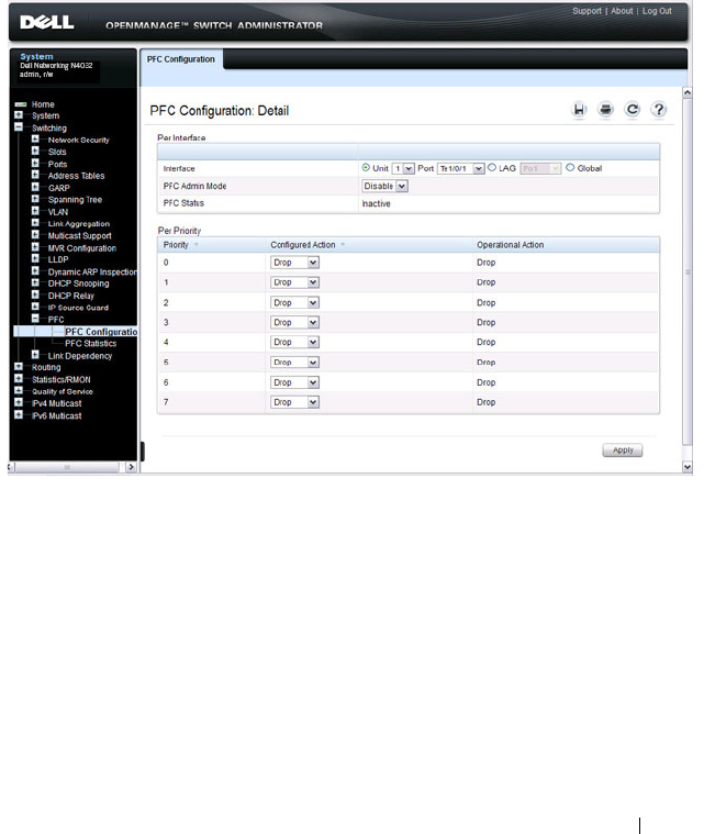
Configuring Data Center Bridging Features 987
PFC Configuration Page
Use the PFC Configuration page to enable priority flow control on one or
more interfaces and to configure which priorities are subject to being paused
to prevent data loss.
To display the PFC Configuration page, click Switching
→
PFC
→
PFC
Configuration in the navigation menu.
Figure 29-1. PFC Configuration
PFC Statistics Page
Use the PFC Statistics page to view the PFC statistics for interfaces on the
switch.
To display the PFC Statistics page, click Switching
→
PFC
→
PFC Statistics
in the navigation menu.
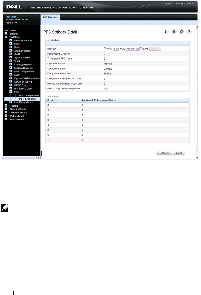
988 Configuring Data Center Bridging Features
Figure 29-2. PFC Statistics
Configuring PFC Using the CLI
Beginning in Privileged EXEC mode, use the following commands to
configure PFC.
NOTE: If DCBx is enabled and the switch is set to autoconfigure from a DCBX
peer, configuring PFC is not necessary because the DCBx protocol automatically
configures the PFC parameters.
Command Purpose
configure Enter global configuration mode.

Configuring Data Center Bridging Features 989
interface
interface
Enter interface configuration mode for the specified
interface. The
interface
variable includes the interface type
and number, for example tengigabitethernet 1/0/3.
You can also specify a range of interfaces with the interface
range command, for example, interface range
tengigabitethernet 1/0/8-12 configures interfaces 8, 9, 10,
11, and 12.
datacenter-bridging Enter the Data Center Bridging mode. PFC commands are
issued from within this mode.
priority-flow-control
mode on
Enable PFC on the interface(s)
NOTE: It is unnecessary to set the priority flow control to
enable if the lldp dcbx port-role auto-down or lldp dcbx port-
role auto-up command has already been applied.
priority-flow-control
priority
priority-id
{drop
| no-drop}
Use the no-drop option to enable the priority group for
lossless behavior. To enable lossy behavior, use the drop
form of the command.
priority-id
— Specify the IEEE 802.1p priority value
(range: 0–7)
NOTE: Only two queues can be set to no-drop at one time.
CTRL + Z Exit to Privileged EXEC mode.
show interfaces
datacenter-bridging
[
interface
| port-channel
port-channel-id
]
Display the datacenter-bridging configuration, status and
counters for a given interface.
clear priority-flow-
control statistics
[
interface
| port-channel
port-channel-id
]
Clear all PFC statistics or the PFC statistics for the
specified interface.
Command Purpose

990 Configuring Data Center Bridging Features
PFC Configuration Example
The network in this example handles both data and voice traffic. Because the
voice traffic is time sensitive, it requires a higher priority than standard data
traffic. The voice traffic uses VLAN 100 and has an 802.1p priority of 5, which
is mapped to hardware queue 4. IP phones are connected to ports 3, 5, and 10,
so PFC is enabled on these ports with 802.1p priority 5 traffic as no-drop. The
configuration also enables VLAN tagging so that the 802.1p priority is
identified. This example assumes the voice VLAN (VLAN 100) has already
been configured. The administrator may need to perform other configuration
steps to ensure suitable network operation, including configuring the
bandwidth allocation for the drop and no-drop priorities or to enable or
disable the DCBX protocol.
1
Map 802.1p priority 5 to traffic class 4. The following command changes
the priority to traffic class mapping to be one-to-one, based upon the
default switch settings. For lossless service, a priority must be mapped one-
to-one to a traffic class. For more information about traffic classes, see
"Configuring Class-of-Service" on page 1313. For a complete example of
manually configuring a
N4000
switch for iSCSI with PFC, refer to "iSCSI
Optimization Configuration Examples" on page 473.
console#configure
console(config)#classofservice dot1p-mapping 5 4
2
Enter Interface Configuration mode for ports 3, 5, and 10, and then enter
Data Center Bridging mode for these ports.
console(config)#interface range te1/0/3, te1/0/5,
te1/0/10
console(config-if)#datacenter-bridging
3
Enable PFC and configure traffic marked with 802.1p priority 5 to be
paused rather than dropped when congestion occurs.
console(config-dcb)#priority-flow-control mode on
console(config-dcb)#priority-flow-control
priority 5 no-drop
CAUTION: All ports may be briefly shutdown when modifying either flow
control (FC) or PFC settings. PFC uses a control packet defined in
802.1Qbb and is not compatible with IEEE 802.3 Annex 31B flow
control.

Configuring Data Center Bridging Features 991
console(config-dcb)#exit
4
Enable VLAN tagging on the ports so the
802.1p priority is identified.
Trunk mode can also be enabled on port-channels.
console(config-if)#switchport mode trunk
console(config-if)#exit

992 Configuring Data Center Bridging Features
DCB Capability Exchange
The Data Center Bridging Exchange Protocol (DCBx) is used by DCB
devices to exchange configuration information with directly connected peers.
DCBx uses type-length-value (TLV) information elements over LLDP to
exchange information, so LLDP must be enabled on the port to enable the
information exchange. By default, LLDP is enabled on all ports. For more
information, see "Discovering Network Devices" on page 761.
The main objective of DCBx is to perform the following operations:
•
Discovery of DCB capability in a peer
: DCBx is used to learn about the
capabilities of the peer device. It is a means to determine if the peer device
supports a particular feature such as PFC.
•
DCB feature misconfiguration detection
: DCBx can be used to detect
misconfiguration of a feature between the peers on a link.
Misconfiguration detection is feature-specific because some features may
allow asymmetric configuration.
•
Peer configuration of DCB features
: DCBx can be used by a device to
perform configuration of DCB features in its peer device if the peer device
is willing to accept configuration.
For discussion and examples of configuring iSCSI with DCBX, refer to
"Configuring iSCSI Optimization" on page 459.
The DCBx protocol supports the propagation of configuration information
for the following features:
• Enhanced Transmission Selection (ETS)
• Priority-based Flow Control (PFC)
• Application Priorities
These features use DCBx to send and receive device configuration and
capability information to the peer DCBx device.
The Application Priorities information is simply captured from the peer and
potentially propagated to other peers by the DCBx component, as well as
being configured when iSCSI is enabled on an operationally active PFC port.
DCBX information is carried over LLDP, which is a link-local protocol. When
configuring links in a port-channel to use DCBX, the DCBX settings should
be the same for all links in the port-channel.

Configuring Data Center Bridging Features 993
Interoperability with IEEE DCBx
To be interoperable with legacy industry implementations of the DCBx
protocol, The Dell Networking N4000 switches use a hybrid model to support
both the IEEE version of DCBx (IEEE 802.1Qaz) and legacy DCBx versions.
The N4000 switch automatically detects whether a peer is operating with
either of the two CEE DCBx versions or the IEEE standard DCBx version
(the default mode). You can also configure DCBx to manually select one of
the legacy versions or IEEE standard mode. In auto-detect mode, the switch
starts operating in IEEE DCBx mode on a port, and if it detects a legacy
DCBx device based on the OUI of the organization TLV, then the switch
changes its DCBx mode on that port to support the version detected. There is
no timeout mechanism to move back to IEEE mode. If the DCBx peer times
out, multiple peers are detected, the link is reset (link down/up) or if
commanded by the operator, DCBx resets its operational mode to IEEE.
The interaction between the DCBx component and other components
remains the same irrespective of the operational mode it is executing. For
instance, the DCBx component interacts with PFC to get needed
information to pack the TLVs to be sent out on the interface. Based on the
operational control mode of the port, DCBx packs it in the proper frame
format.
DCBx and Port Roles
The behavior of each port is dependent on its operational mode and that of
other ports in the stack. The port mode is a DCBx configuration item that is
passed to the DCBx clients to control the processing of their configuration
information. There are four port roles:
1
Manual
2
Auto-Upstream
3
Auto-Downstream
4
Configuration Source
Ports operating in the manual role do not have their configuration affected by
peer devices or by internal propagation of configuration. These ports have
their operational mode, traffic classes, and bandwidth information specified

994 Configuring Data Center Bridging Features
explicitly by the operator. These ports advertise their configuration to their
peer if DCBx is enabled on that port. Incompatible peer configurations are
logged and counted with an error counter.
The default operating mode for each port is manual. A port that is set to
manual mode sets the willing bit for DCBx client TLVs to false. Manually-
configured ports never internally propagate or accept internal or external
configuration from other ports; in other words, a manual configuration
discards any automatic configuration. Manually-configured ports may notify
the operator of incompatible configurations if client configuration exchange
over DCBx is enabled. Manually configured ports are always operationally
enabled for DCBx clients, regardless of whether DCBx is enabled.
Operationally enabled means that the port reports that it is able to operate
using the current configuration.
A port operating in the auto-upstream role advertises a configuration, but is
also willing to accept a configuration from the link-partner and propagate it
internally to the auto-downstream ports, as well as receive configuration
propagated internally by other auto-upstream ports. Specifically, the willing
parameter is enabled on the port and the recommendation TLV is sent to the
peer and processed if received locally. The first auto-upstream port to
successfully accept a compatible configuration becomes the configuration
source. The configuration source propagates its configuration to other auto-
upstream and auto-downstream ports. Only the configuration source may
propagate configuration to other ports internally. Auto-upstream ports that
receive internally propagated information ignore their local configuration and
utilize the internally propagated information.
Peer configurations received on auto-upstream ports other than the
configuration source result in one of two possibilities. If the configuration is
compatible with the configuration source, then the DCBx client becomes
operationally active on the upstream port. If the configuration is not
compatible with the configuration source, then a message is logged indicating
an incompatible configuration, an error counter is incremented, and the
DCBx client is operationally disabled on the port. The expectation is that the
network administrator configures the upstream devices appropriately so that
all such devices advertise a compatible configuration.
A port operating in the auto-downstream role advertises a configuration but is
not willing to accept one from the link partner. However, the port will accept a
configuration propagated internally by the configuration source. Specifically,

Configuring Data Center Bridging Features 995
the willing parameter is disabled on auto-downstream. By default, auto-
downstream ports have the recommendation TLV parameter enabled. Auto-
downstream ports that receive internally propagated information ignore their
local configuration and utilize the internally propagated information. Auto-
downstream ports propagate PFC, ETS, and application priority information
received from the configuration source.
In the Configuration Source role, the port has been manually selected to be
the configuration source. Configuration received over this port is propagated
to the other auto configuration ports, however, no automatic election of a
new configuration source port is allowed. Events that cause selection of a new
configuration source are ignored. The configuration received over the
configuration source port is maintained until cleared by the operator (set the
port to the manual role).
Since it is not possible to configure the port role for a port-channel, it is
recommended that the individual links have an identical port role configured
on all links in the port-channel (auto-up or auto-down). Since only one port
in the system can be configured as the configuration source, configuring
interfaces as auto-up is a preferable alternative to a config-source setting.
Configuration Source Port Selection Process
When an auto-upstream or auto-downstream port receives a configuration
from a peer, the DCBx client first checks if there is an active configuration
source. If there is a configuration source already selected, the received
configuration is checked against the local port operational values as received
from the configuration source, and if compatible, the client marks the port as
operationally enabled. If the configuration received from the peer is
determined to not be compatible, a message is logged, an error counter is
incremented and the DCBx clients become operationally disabled on the
port. Operationally disabled means that PFC will not operate over the port.
The port continues to keep link up and exchanges DCBx packets. If a
compatible configuration is later received, the DCBx clients will become
operationally enabled.
If there is no configuration source, a port may elect itself as the configuration
source on a first-come, first-serve basis from the set of eligible ports. A port is
eligible to become the configuration source if the following conditions are
true:
• No other port is the configuration source.

996 Configuring Data Center Bridging Features
• The port role is auto-upstream.
• The port is enabled with link up and DCBx enabled.
• The port has negotiated a DCBx relationship with the partner.
• The switch is capable of supporting the received configuration values,
either directly or by translating the values into an equivalent configuration.
Whether or not the peer configuration is compatible with the configured
values is NOT considered.
The newly elected configuration source propagates DCBx client information
to the other ports and is internally marked as being the port over which
configuration has been received. Configuration changes received from the
peer over the configuration source port are propagated to the other auto
configuration ports. Ports receiving auto configuration information from the
configuration source ignore their current settings and utilize the
configuration source information.
When a configuration source is selected, all auto-upstream ports other than
the configuration source are marked as willing disabled.
To reduce flapping of configuration information, if the configuration source
port is disabled, disconnected, or loses LLDP connectivity, the system clears
the selection of configuration source port (if not manually selected) and
enables the willing bit on all auto-upstream ports. The configuration on the
auto configuration ports is not cleared (configuration holdover). If the user
wishes to clear the configuration on the system in this scenario, the user can
put the configuration source port into manual mode.
When a new port is selected as the configuration source, it is marked as the
configuration source, the DCBx configuration is refreshed on all auto
configuration ports, and each port may begin configuration negotiation with
their peer again (if any information has changed).
Disabling DCBX
If it is desired to disable DCBX, the network operator can use the following
commands to eliminate the transmission of DCBX TLVs in the LLDP frames
on an interface:
no lldp tlv-select dcbxp application-priority
no lldp tlv-select dcbxp congestion-notification
no lldp tlv-select dcbxp ets-config

Configuring Data Center Bridging Features 997
no lldp tlv-select dcbxp ets-recommend
no lldp tlv-select dcbxp pfc
These commands eliminate only the DCBX TLVs from use by LLDP. They do
not otherwise affect any manually configured DCBX capabilities or the
normal operation of LLDP.
Configuring DCBx
You can use the CLI to configure DCBX on N4000 switches.
Beginning in Privileged EXEC mode, use the following commands to
configure DCBx.
Command Purpose
configure Enter global configuration mode.
lldp dcbx version {auto
| cin | cee | ieee}
Optionally configure the administrative version for the
DCBx protocol:
• auto—Automatically select the version based on the peer
response (default)
• cin—Force the mode to Cisco-Intel-Nuova. (DCBx 1.0)
• cee—Force the mode to CEE (DCBx 1.06)
• ieee—Force the mode to IEEE 802.1Qaz
lldp tlv-select dcbxp
[pfc | application-
priority]
Enable LLDP to send specific DCBx TLVs if LLDP is
enabled to transmit on the given interface. Entering the
command with no parameters enables transmission of all
TLVs.
• pfc—Transmit the PFC configuration TLV
• application-priority—Transmit the application priority
TLV
interface
interface
Enter interface configuration mode for the specified
interface. The
interface
variable includes the interface type
and number, for example tengigabitethernet 1/0/3.
You can also specify a range of interfaces with the interface
range command, for example, interface range
tengigabitethernet 1/0/8-12 configures interfaces 8, 9, 10,
11, and 12.

998 Configuring Data Center Bridging Features
lldp tlv-select dcbxp
[pfc | application-
priority]
Override the global configuration for the LLDP DCBx
TLVs on this interface. Entering the command with no
parameters enables transmission of all TLVs.
• pfc—Transmit the PFC configuration TLV.
• application-priority—Transmit the application priority
TLV.
lldp dcbx port-role
{auto-up |auto-down |
manual | configuration-
source}
Configure the DCBx port role on the interface:
•
auto-up
—Advertises a configuration, but is also willing to
accept a configuration from the link-partner and
propagate it internally to the auto-downstream ports as
well as receive configuration propagated internally by
other auto-upstream ports. These ports have the willing
bit enabled. These ports should be connected to FCFs.
•
auto-down
—Advertises a configuration but is not willing
to accept one from the link partner. However, the port will
accept a configuration propagated internally by the
configuration source. These ports have the willing bit set
to disabled. Selection of a port based upon compatibility
of the received configuration is suppressed. These ports
should be connected to a trusted FCF.
•
manual
—Ports operating in the Manual role do not have
their configuration affected by peer devices or by internal
propagation of configuration. These ports will advertise
their configuration to their peer if DCBx is enabled on
that port. The willing bit is set to disabled on manual role
ports.
•
configuration-source
—In this role, the port has been
manually selected to be the configuration source.
Configuration received over this port is propagated to the
other auto configuration ports. Selection of a port based
upon compatibility of the received configuration is
suppressed. These ports should be connected to a trusted
FCF. These ports have the willing bit enabled.
CTRL + Z Exit to Privileged EXEC mode.
Command Purpose

Configuring Data Center Bridging Features 999
Enhanced Transmission Selection
Networks classify and prioritize traffic to provide different service
characteristics to end user traffic flows. Administrators may wish to guarantee
or limit bandwidth for certain traffic, ensure lossless behavior for other traffic,
and control the queue discipline/drop characteristics for best-effort traffic.
Additionally, it is desirable for a switch to support sharing bandwidth among
bursty sources while still enabling prioritization of time-sensitive or
management traffic that requires minimum latency.
Enhanced transmission selection (ETS) provides uniform management for
sharing bandwidth between congestion managed and traditional classes on a
single bridged network. Using priority-based processing and weight
allocations, Traffic Class Groups (TCGs) carrying different types of traffic
such as LAN, SAN, and management traffic can be configured to provide
minimum bandwidth guarantees, unused bandwidth sharing, and lossless or
best-effort transmit characteristics. Dell Networking N4000 switches support
strict priority and Weighted Deficit Round Robin (WDRR) scheduling with
up to two lossless traffic classes. WDRR schedules traffic based on average
bandwidth consumed vs. frame counts.
ETS Operation
The normal (default) operation of Dell Networking switches, when
uncongested, is that packets are scheduled for output in the order in which
they are received, that is, using FIFO scheduling. The class of service (CoS)
mechanism enables the administrator to schedule packets for output ahead of
other packets when the switch is congested, choose which type of packets to
drop when the switch is congested, and assign a minimum bandwidth
guarantee to ensure scheduling fairness. These mechanisms operate at the
CoS queue level; that is, the minimum bandwidth guarantees are made
across all configured CoS queues.
show lldp tlv-select
interface {all |
interface
}
Display the interface TLV configuration for all interfaces
or for the specified interface.
show lldp dcbx interface
{all status |
interface
[detail]}
Display the interface TLV configuration for all interfaces
or for the specified interface.
Command Purpose

1000 Configuring Data Center Bridging Features
ETS provides a second level of scheduling for packets selected for
transmission by the CoS scheduler. ETS operates at the traffic class group
(TCG) level and supports sharing of bandwidth across TCGs, bandwidth
assignment for each TCG, and queue discipline (drop behavior) for each
TCG. N4000 switches support three TCGs internally, up to two of which may
be configured as lossless.
When a packet arrives on an ingress port, it is forwarded to the appropriate
CoS queue based upon the dot1p mapping. The dot1p mapping maps the
user priority contained in the received VLAN Priority Tag to the traffic class
or uses the default port assignment. A traffic class identifies a particular CoS
queue. If the ingress port is configured to use 802.1p CoS mapping and the
port is configured to trust the user priority value in the received frame, then
the frame is forwarded to the appropriate CoS queue per its 802.1p user
priority value.
At the first level of egress scheduling, each of the configured attributes of a
CoS queue, namely scheduler algorithm, min-bandwidth and drop
mechanism, are honored, and the packet is either dropped or forwarded to
next level. Only frames selected by the first level scheduler are forwarded to
the second level.
Strict priority traffic classes are serviced first in order of traffic class number. A
strict priority traffic class is one that is configured as strict priority or has a
traffic class group weight of 0 (unlimited bandwidth). Within a strict priority
traffic class, frames are serviced (as determined by the traffic class number) in
CoS queue priority order from the highest (6) to the lowest (0).
Each traffic class has an internal weight equal to the traffic class number plus
one. After the strict priority traffic classes have been serviced, the remaining
traffic classes are serviced according to their internal weight. For example, if
CoS queues 0, 1, and 2 have an equal offered load toward a congested output
port, CoS queue 2 will receive 3/6 of the bandwidth, CoS queue 1 will receive
2/6 of the bandwidth, and CoS queue 0 will receive 1/6 of the bandwidth.
NOTE: Minimum bandwidth guarantees and scheduling mechanisms apply only
when the switch is congested. When the switch is not congested, packets
egress the switch as soon as they are received.

Configuring Data Center Bridging Features 1001
The minimum bandwidth setting can be used to override the strict priority
and weighted settings. The highest numbered strict priority queue will
receive no more bandwidth than 100 percent minus the sum of the minimum
bandwidth percentages assigned to the other queues. If used, it is
recommended that minimum bandwidth percentages only be set high
enough to ensure a minimum level of service for any queue; i.e., the sum of
the minimum bandwidth percentages is a fraction of 100%. This ensures that
the system can respond to bursts in traffic. Setting the minimum bandwidths
such that they sum to 100% effectively sets the scheduler such that no queue
can exceed its minimum bandwidth percentage when congestion occurs.
Each CoS queue in the first level scheduler is mapped to one of the three
traffic class groups in the second level scheduler. There, frames are serviced
using the TCG configuration. The minimum bandwidth guarantee is first
calculated across the TCGs. Strict priority TCGs are scheduled first but have
their bandwidth reduced by the minimum bandwidth guarantees configured
on other TCGs. Strict priority TCGs are scheduled from highest numbered
TCG to lowest. When all TCGs have met their minimum bandwidth limits
(or the queues are empty), TCGs that have not met their maximum
bandwidth limit are scheduled. Once the limits for a TCG are satisfied
(maximum bandwidth, no frames available for transmission, etc.), the
scheduler moves to the next TCG.
If no minimum or maximum bandwidth limits are configured, TCGs are
serviced by the second-level scheduler using the configured TCG weights to
define the relative bandwidth allocation among the TCGs. When an egress
port is congested, packets are selected for discard using the configured tail-
drop or WRED discipline. Minimum TCG bandwidth, maximum TCG
bandwidth, and TCG weights are metered to within approximately 3% of the
link bandwidth.
In the case that all TCGs are configured as strict priority, inter-TCG
scheduling reverts to Weighted Deficit Round Robin scheduling based on the
configured TCG weights.
NOTE: CoS queue 7 is reserved for internal traffic. Non-strict priority CoS queues
are serviced with WDRR scheduling using the bandwidth available after strict
priority traffic is serviced.

1002 Configuring Data Center Bridging Features
Commands
This section provides information about the commands you use to manually
configure and monitor ETS. For more information about the commands, see
the
Dell Networking N2000, N3000, and N4000 Series Switches CLI
Reference Guide
at support.dell.com/manuals. On N4000 switches, the
following steps are not required if using the DCBX protocol to obtain ETS
configuration from an auto-configuration source.
For information on configuring iSCSI and DCBX, refer to "Configuring
iSCSI Optimization" on page 459.
Command Purpose
classofservice traffic-
class-group
Maps the internal Traffic Class to an internal Traffic Class
Group (TCG). The Traffic Class can range from 0-6,
although the actual number of available traffic classes
depends on the platform.
traffic-class-group max-
bandwidth
Specifies the maximum transmission bandwidth limit for
each TCG as a percentage of the interface rate. Also
known as rate shaping, this has the effect of smoothing
temporary traffic bursts over time so that the transmitted
traffic rate is bound.
traffic-class-group min-
bandwidth
Specifies the minimum transmission bandwidth
guaranteed for each TCG before processing frames from
lower numbered TCGs on an interface.
traffic-class-group strict Activates the strict priority scheduler mode for each
specified TCG.
traffic-class-group
weight
Specifies the scheduling weight for each TCG. The
scheduler attempts to balance the traffic selected for
transmission from the TCGs such that, when the switch is
congested, traffic is selected from the round robin
configured TCGs in proportion to their weights.
show classofservice
traffic-class-group
Displays the Traffic Class to Traffic Class Group mapping.
show interfaces traffic-
class-group
Displays the Traffic Class to Traffic Class Group mapping

Configuring Data Center Bridging Features 1003
ETS Configuration Example
This example configures four classes of traffic:
1. Enable Trust Mode on an Interface
The following command enables the use of the dot1p priority of the incoming
packet. It may be configured on a single interface, a range of interfaces or all
interfaces. By default, ports are configured to trust the incoming user priority.
console(config-if-Te1/0/1)#classofservice trust dot1p
To show the configured trust mode on an interface, use the following
command:
console#show classofservice trust tengigabitethernet 1/0/1
Class of Service Trust Mode: Dot1P
2. Map Dot1p Priority to CoS Queues
This step maps dot1p priorities to the CoS queues. This mapping places the
incoming packet in the selected CoS queue based on the dot1p priority. It
may be configured on a single interface, a range of interfaces, or all interfaces.
To ensure lossless behavior, the dot1p priority must be mapped one to one to
a CoS queue for the lossless priorities. Up to two lossless priorities may be
configured on N4000 switches. CoS queue 7 is reserved by the system and is
not assignable. It is generally recommended that the administrator utilize
CoS queues 0-3 as CoS queues 4-6 may be utilized by the system for other
types of system traffic, e.g. routing protocol PDU handling. Frames with
different user priorities assigned to a single CoS queue receive equal
treatment.
This example maps user priorities 0, 1, and 2 to CoS queue 0 (background or
best effort traffic), user priorities 3 and 4 to CoS queues 1 and 2 (iSCSI
traffic), and all other priorities to CoS queue 2 (low latency and network
control traffic).
Best effort traffic CoS Queue 0 for untagged and VLAN-tagged
frames with VPTs 0, 1, and 2
Lossless iSCSI traffic CoS Queues 1 & 2 for VLAN tagged frames with
VPTs 3 & 4 respectively
Expedited traffic CoS Queue 3 on VLAN tagged frames with VPTs
5, 6, and 7

1004 Configuring Data Center Bridging Features
console(config-if-Te1/0/2)#classofservice dot1p-mapping 0 0
console(config-if-Te1/0/2)#classofservice dot1p-mapping 1 0
console(config-if-Te1/0/2)#classofservice dot1p-mapping 2 0
console(config-if-Te1/0/2)#classofservice dot1p-mapping 3 1
console(config-if-Te1/0/2)#classofservice dot1p-mapping 4 2
console(config-if-Te1/0/2)#classofservice dot1p-mapping 5 3
console(config-if-Te1/0/2)#classofservice dot1p-mapping 6 3
console(config-if-Te1/0/2)#classofservice dot1p-mapping 7 3
To show dot1p priority for an interface, use the following command:
console#show classofservice dot1p-mapping tengigabitethernet 1/0/1
User Priority Traffic Class
------------- -------------
0 0
1 0
2 0
3 1
4 2
5 3
6 3
7 3
3. Configure Minimum Bandwidth on the CoS Queues (optional)
This step configures the minimum bandwidth guarantee for each CoS queue
when the switch is congested. If the switch is not congested, this setting has
no effect. The min-bandwidth setting guarantees that any particular CoS
queue is serviced often enough to ensure that the offered load can achieve the
minimum transfer rate. The bandwidth is measured internally as bytes
transferred per second. The minimum bandwidth setting is enforced on the
egress queue; it does not rate-limit incoming frames. The minimum
bandwidth setting is configured as a percentage of the total bandwidth and
must be less than or equal to 100%. It may be configured on a single interface,
a range of interfaces, or all interfaces.
The minimum bandwidth setting on the CoS queues comes in to play when
there is congestion among the CoS queues belonging to a single TCG. This is
an optional setting and is not generally required, as the secondary scheduler
has the capability of guaranteeing minimum bandwidth for a TCG. If this
value is set, the sum of the individual minimum bandwidths of the CoS
queues belonging to any TCG should be set to the same value as the
minimum bandwidth value of the TCG in the secondary scheduler, or no
minimum bandwidth value should be configured for the TCG.

Configuring Data Center Bridging Features 1005
CAUTION: Sharing of bandwidth among CoS Queues is disabled if the sum of the
minimum bandwidth settings equals 100%.
console(config-if-Te1/0/1)#cos-queue min-bandwidth 20 35 35 10 0 0 0
4. Configure the Scheduler Mode for the CoS Queues
This step enables strict priority scheduling on one or more CoS queues
(traffic classes). Strict priority scheduling ensures that packets assigned to a
higher CoS queue number are serviced before packets assigned to lower CoS
queue numbers. The strict priority setting does not restrict frame ingress. Use
the 'no' command to disable strict priority mode scheduling.
It is recommended that all queues enabled for strict priority scheduling be
assigned to a single strict-priority-enabled TCG other than TCG0.
The following example sets CoS queue (traffic class) number 3 to be serviced
with strict priority:
console(config-if-Te1/0/1)#cos-queue strict 3
To show the minimum bandwidth and scheduler modes for CoS queues, use
the following command.
console#show interfaces cos-queue tengigabitethernet 1/0/1
Interface...................................... Te1/0/1
Interface Shaping Rate......................... 0 kbps
WRED Decay Exponent............................ 9
Queue Id Min. Bandwidth Scheduler Type Queue Management Type
-------- -------------- -------------- ---------------------
0 20 Weighted Tail Drop
1 35 Weighted Tail Drop
2 35 Weighted Tail Drop
3 10 Strict Tail Drop
4 0 Weighted Tail Drop
5 0 Weighted Tail Drop
6 0 Weighted Tail Drop
5. Map the CoS Queues to TCGs
In this step, CoS queues are mapped to Traffic Class Groups (TCGs). Since
TCGs are serviced from highest numbered TCG to lowest, higher priority
traffic should be assigned to higher numbered TCGs. In general, strict

1006 Configuring Data Center Bridging Features
priority traffic (typically control plane or low bandwidth, low latency traffic) is
assigned the highest numbered TCG. It is recommended that WDRR queues
be assigned to TCG0.
The mapping may be configured on a single interface, a range of interfaces, or
all the interfaces.
It is required that TCGs always be assigned in order from 0 to 2. It is further
recommended that the operator always utilize consecutive TCGs starting
with TCG 0; for example, use TCG 0 and 1 vs. TCG 0 and 2 only.
This example assigns best effort traffic to TCG 0, lossless traffic to TCG 1,
and expedited service traffic to TCG 2.
console(config-if-Te1/0/1)# classofservice traffic-class-group 0 0
console(config-if-Te1/0/1)# classofservice traffic-class-group 1 1
console(config-if-Te1/0/1)# classofservice traffic-class-group 2 1
console(config-if-Te1/0/1)# classofservice traffic-class-group 3 2
To show the CoS queue to TCG mapping, use the following command:
console#show classofservice traffic-class-group tengigabitethernet
1/0/1
Traffic Class Traffic Class Group
------------- ------------------
0 0
1 1
2 1
3 2
4 0
5 0
6 0
6. Set the Weight for Each TCG
This step configures the scheduling weight for each TCG. The weight
percentage configures the scheduler to ensure that each TCG is nominally
serviced in the ratio specified.
Each WDRR TCG should be assigned a nonzero weight. Weights may be
configured on a single interface, a range of interfaces, or all interfaces, and
must sum to 100%. It is recommended that strict priority TCGs be assigned a
weight of 0%, since they are processed first and ignore the configured TCG
weight.

Configuring Data Center Bridging Features 1007
It is recommended that the sum of minimum bandwidth percentages
configured on the CoS queues mapped to any TCG be less than or equal to
that of the weight percentage configured for the TCG, so that packets are not
dropped due to the congestion in the TCG.
In example below, the TCG0 and TCG1 are allocated 30% and 70% of the
bandwidth remaining after servicing TCG2 (strict priority) traffic. TCG2
traffic is handled with strict priority but can only consume up to 100% minus
the sum of the minimum bandwidths of TCG0 and TCG1 (60%).
console(config-if-Te1/0/1)#traffic-class-group weight 30 70 0
7. Set the Minimum Bandwidth for Each TCG (optional)
In this step, the minimum bandwidth is configured for each TCG while in
congestion. The minimum bandwidth setting ensures that a TCG is serviced
during congestion even if a higher priority TCG has an offered load greater
than 100% minus the minimum bandwidth assigned to the other TCGs.
The minimum bandwidth is enforced on the egress TCG regardless of the
scheduling mode and does not directly affect incoming traffic. The minimum
bandwidth for a TCG is configured as a percentage of the total bandwidth,
and the configured minimum bandwidths may sum to less than 100%. The
sum may not exceed 100%. Minimum bandwidth may be configured on a
single interface, a range of interfaces, or all interfaces. It is recommended that
the minimum bandwidth for a TCG be configured to be less than or equal to
the weight of the TCG.
CAUTION: Sharing of bandwidth among TCGs is disabled if the sum of the
minumum bandwidth settings equals 100%.
console(config-if-Te1/0/1)#traffic-class-group min-bandwidth 10 50 0
8. Set the Maximum Bandwidth for each TCG (optional)
In this step, the maximum bandwidth for each TCG is configured. The
bandwidth allowed for the TCG will never exceed the maximum bandwidth
configured, even if configured for strict priority. This limit is configured as a
percentage of the total bandwidth and is used to shape egress traffic bursts to
no greater than the configured value. The maximum bandwidth may be
configured on a single interface, range of interfaces or all interfaces. When
configured to be 0, unlimited bandwidth is allowed on the TCG.

1008 Configuring Data Center Bridging Features
It is recommended that the maximum bandwidth be configured to be greater
than the minimum bandwidth or the weight or be configured to 0 (unlimited
burst size).
console(config-if-Te1/0/1)#traffic-class-group max-bandwidth 50 90 20
9. Set the Scheduler Modes for the TCGs
This step enables strict priority scheduling on TCGs. Strict priority
scheduling on multiple TCGs prioritizes traffic from the highest numbered
TCG for transmission first. Strict priority scheduling on a single TCG selects
that TCG for transmission before the WDRR TCGs. Use the 'no' command
to disable strict priority scheduling. It is recommended that all CoS queues
enabled for strict priority scheduling be assigned to a single TCG other than
TCG0. This scheme allows a larger number of priorities to be configured as
strict priorities.
console(config-if-Te1/0/1)#traffic-class-group strict 2
To show the weight, minimum bandwidth, maximum bandwidth, and
scheduler modes of the TCGs, use the following command:
console#show interfaces traffic-class-group tengigabitethernet 1/0/1
Interface...................................... Te1/0/1
Traffic Class Min. Max
Group Bandwidth Bandwidth Weight Scheduler Type
------------ --------- ------------ ------ --------------
0 10 50 30 Weighted Round Robin
1 50 90 70 Weighted Round Robin
2 0 20 0 Strict

Configuring Data Center Bridging Features 1009
ETS Theory of Operation
First Level of Scheduling
To understand the first level of scheduling, consider Table 29-1. Assume that
we have eight ingress ports, each one receiving line rate traffic with one dot1p
priority each. The table shows the mapping of dot1p priorities to the cos-
queues, the min-bandwidth settings, and scheduler modes.
In this scenario, the input to the TCGs is as follows:
• All of the pri0 traffic reaches the TCG0. This is because there is no other
priority contending for the same TCG. The minimum bandwidth setting
on the CoS queue does not have any effect.
• TCG1 would receive 10% each of pri1 and pri3 and 80% of pri2. Even
though strict mode is enabled for pri2, the minimum bandwidth of pri1
and pri3 is first honored before applying strict mode on pri2.
• TCG2 receives 25% each of pri4 and pri5 traffic and the other 50% can be
of pri6 or pri7. This is based on the minimum bandwidth ratio, which is
15:15:30, converted to 1:1:2.
Table 29-3. First Level of Scheduling
Dot1p
Priority
CoS Queue CoS Min-
bandwidth
Scheduler TCG Input to TCG
0 0 10 WRR 0100% of pri0
1 1 10 WRR 110% each of
2 2 10 Strict 1pri1, pri3 and
3 3 10 WRR 180% of pri2
4 4 15 WRR 225% each
5 5 15 WRR 2of pri4, pri5
6 6 30 WRR 2and 50% of
7 6 – – – pri6/pri7
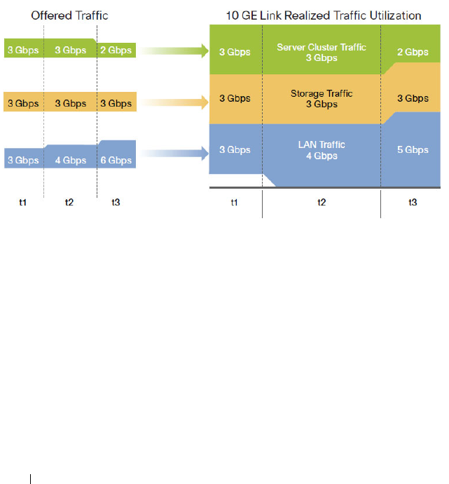
1010 Configuring Data Center Bridging Features
Second Level of Scheduling
To consolidate different traffic classes within different traffic types in a
typical DCB environment, ETS provides an operational model for
prioritization and bandwidth allocation for traffic. Figure 29-3 illustrates a
typical example that consolidates three traffic types on a single 10GE link. For
consolidation to be effective all traffic types must be serviced according to
their requirements. For instance, SAN traffic must be guaranteed to be
lossless, and the server cluster traffic (IPC) should be guaranteed a
sufficiently high priority to meet the requirement of low latency.
Figure 29-3. Converged Link on the DCB Environment
In this example, to ensure that the server cluster traffic has low latency, it may
be assigned to a TCG—say, TCG0—and a strict mode of scheduling is
enabled on this group (weight set to 0%). SAN traffic can be assigned to
TCG1 and LAN to TCG2. The TCG1 and TCG2 can be set to a weight of
50% each. With these configurations, Figure 29-3 illustrates how the load is
managed at different times.
When the offered load is 3 Gbps for each traffic type at time t1, the allocated
bandwidth for TCG1 and TCG2 is 3.5 Gbps each. All traffic types, including
IPC, SAN, and LAN, are allowed to be transmitted, since the offered load is
under the allocated bandwidth.

Configuring Data Center Bridging Features 1011
At time t2, a burst of LAN traffic is incoming at the rate of 4 Gbps, this burst
is allowed to borrow the unused 0.5 Gbps bandwidth from SAN TCG and
transmitted since the offered load of SAN is only 3 Gbps.
At time t3, when the offered load of IPC falls to 2 Gbps and the bursty LAN
traffic is at 6 Gbps, the available bandwidth for SAN and LAN is 4 Gbps each
according to the TCG weights, which are set as 50% each. However, ETS
allows the LAN traffic to borrow unused bandwidth from SAN traffic, and
then 5 Gbps of LAN traffic is transmitted.
Recommendations and Notes
Lossless traffic must map user priorities one-to-one onto CoS queues.
Lossless traffic must always be carried within a VLAN-tagged frame to
differentiate it from untagged best-effort LAN control traffic, such as ARP
and LLDP.
Strict-priority CoS queues may starve other CoS queues of traffic if the
offered load of the strict-priority CoS queues equals or exceeds the available
capacity of the egress interfaces. It is recommended that either a CoS-queue-
level min-bandwidth setting be utilized to ensure a minimum amount of
bandwidth is processed on the non-strict-priority queues if there is a
possibility that the strict priority traffic is not limited in bandwidth by some
other means.
It is recommended that the sum of the minimum bandwidth percentages
allocated to the group of CoS queues mapped to a single TCG be less than or
equal to the weight percentage, so that packets are not dropped due to the
congestion in the TCG.
The maximum bandwidth for a TCG should always be configured to be
greater than the minimum bandwidth or the weight of the TCG.
In the case where all TCGs are configured as strict priority, inter-TCG
scheduling is Weighted Deficit Round Robin, using the configured weights.
Configuring CoS queues with a total maximum bandwidth that is less than
the corresponding TCG weight will result in bandwidth being wasted in the
secondary scheduler.
Configuring CoS queues with a total minimum bandwidth that is greater
than the corresponding TCG weight will flood the secondary scheduler and
result in the minimum bandwidth parameter effectively overriding the TCG
weight setting.

1012 Configuring Data Center Bridging Features
Traffic is passed across stacking links using WDRR for all CoS queues. This
will affect the observed behavior of ETS on egress ports scheduling traffic
from over-subscribed stacking links.
The three supported traffic class groups support an industry standard
configuration such that one traffic class group offers lossless service (PFC
enabled using WRR); one traffic class group contains priorities which are best
effort (PFC disabled using WRR); and one traffic class group offers an
expedited service (utilizes strict priority). When auto configuration is
enabled on ports using ETS, the traffic classes are combined according to the
above. Internally, the DCBX TCG mapping is restricted to using three TCGs
regardless of the number of TCGs advertised by the configuration source,
with the strict priority traffic mapped onto TCG 2, lossless traffic mapped
onto TCG1, and all other traffic mapped onto TCG0.
For ETS to be operational in a manually configured environment, the
following minimum steps must be performed:
1
Configure the CoS queue to Traffic Class Group mapping for the egress
ports.
2
Enable the appropriate scheduling algorithm for each TCG.
3
Configure the weight percentage for each TCG.
Variation on the Example Configuration
This example configures three classes of traffic and utilizes the secondary
(ETS) scheduler only:
• Best effort traffic: CoS Queue 0 for untagged and VLAN tagged frames
with VPTs: 0, 1, and 2
• Lossless iSCSI: CoS Queue 1, VLAN tagged frames with VPT equal to 3
• Expedited Traffic: CoS Queue 2, VLAN tagged frames with VPTs: 4, 5, 6, 7
console(config-if-Te1/0/2)#classofservice dot1p-mapping 0 0
console(config-if-Te1/0/2)#classofservice dot1p-mapping 1 0
console(config-if-Te1/0/2)#classofservice dot1p-mapping 2 0
console(config-if-Te1/0/2)#classofservice dot1p-mapping 3 1
console(config-if-Te1/0/2)#classofservice dot1p-mapping 4 2
console(config-if-Te1/0/2)#classofservice dot1p-mapping 5 2
console(config-if-Te1/0/2)#classofservice dot1p-mapping 6 2
console(config-if-Te1/0/2)#classofservice dot1p-mapping 7 2
console(config-if-Te1/0/1)#classofservice traffic-class-group 0 0
console(config-if-Te1/0/1)#classofservice traffic-class-group 1 1

Configuring Data Center Bridging Features 1013
console(config-if-Te1/0/1)#classofservice traffic-class-group 2 2
console(config-if-Te1/0/1)#traffic-class-group weight 30 70 0
console(config-if-Te1/0/1)#traffic-class-group strict 2
N4000 Operation
When DCBx is enabled on manually configured ports, it is not necessary for
the ETS parameters to match, regardless of the version of DCBX negotiated
or configured. Configuration mismatches are logged.
In auto configuration mode, ETS parameters from the configuration source
are checked (Max TCs 3 and bandwidth equal to 100%) and if the system is
capable of performing the configuration, it is accepted and propagated as
received to the other auto-configuration ports. The ETS Recommendation
TLVs are preferred over the ETS Configuration TLVs. Auto-configuration via
DCBX overrides manually configured ETS parameters for auto-configured
ports, however, manual configuration is restored should the port be placed
back into the manual port role.
The ETS parameters received via DCBX are modified and applied to the
system via the DCBX Mapping function as follows (references are to the
802.1Qaz parameters):
• Like traffic classes are combined up to the limits of the system; e.g., no
more than 2 lossless CoS queues may be configured.
• The Priority Assignment Table (user priority to CoS queue mapping) is
utilized by the system to map user priorities to the traffic classes (CoS
queues).
• The TSA Assignment Table is converted to use 3 TCGs internally.
Priorities with like characteristics are combined into TCGs, i.e. strict
priority traffic is combined into a TCG, lossless traffic is combined into a
TCG, etc. Generally, strict priority traffic is mapped onto TCG 2, lossless
traffic is mapped onto TCG1 and best effort traffic is mapped onto TCG0.
• The bandwidths from the TC Bandwidth Table are summed based on the
internal TCG mapping and are used to set the TCG weights. Other
switches may assign bandwidth to strict priority queues. This bandwidth is
counted in the sum to ETS 100% validation check, however, internally the
weight for strict priority queues is ignored and they are configured for
unlimited bandwidth. An implication of this assignment is that the
percentage of bandwidth that may be consumed by a WDRR TCG after

1014 Configuring Data Center Bridging Features
processing strict priority traffic is skewed to be the bandwidth of the
individual TCG divided by the sum of the weights of all WDRR
configured TCGs.
The administrator may configure other parameters to work in conjunction
with the received DCBX configuration, e.g. min-bandwidth per CoS queue
and minimum or maximum bandwidth per TCG.

Managing the MAC Address Table 1015
30
Managing the MAC Address Table
This chapter describes the L2 MAC address table the switch uses to forward
data between ports.
The topics covered in this chapter include:
• MAC Address Table Overview
• Default MAC Address Table Values
• Managing the MAC Address Table (Web)
• Managing the MAC Address Table (CLI)
MAC Address Table Overview
The MAC address table keeps track of the MAC addresses that are associated
with each port to allow the switch to forward unicast traffic through the
appropriate port. This table is sometimes called the bridge table or the
forwarding database.
How Is the Address Table Populated?
The MAC address table can contain two types of addresses:
• Static: The address has been manually configured and does not age out.
• Dynamic: The address has been automatically learned by the switch and
can age out when it is not in use.
Static addresses are configured by the administrator and added to the table.
Dynamic addresses are learned by examining information in the Ethernet
frame.
When a frame arrives on a port, the switch looks at the frame header to learn
the source MAC address of the frame, then adds the address, VLAN ID, and
the ingress port to the MAC address table. The address table is constantly
updated as new addresses are learned, and unused addresses age out.
A frame that has a destination MAC address that matches an entry in the
table is forwarded immediately to the associated port(s)/VLAN(s).
1016 Managing the MAC Address Table
What Information Is in the MAC Address Table?
Each entry in the address table, whether it is static or dynamic, includes the
MAC address, the VLAN ID associated with the MAC address, and the
interface on which the address was learned or configured.
Each port can maintain multiple MAC addresses, and a MAC address can be
associated with multiple VLANs.
How Is the MAC Address Table Maintained Across a Stack?
The MAC address table is synchronized across all stack members. When a
member joins the stack, its previous MAC address table is overwritten by the
table maintained by the stack.
Default MAC Address Table Values
Table 30-1 summarizes the default values for the MAC address table.
Table 30-1. MAC Address Table Defaults
Parameter Default Value
Aging time 300 seconds
Dynamic addresses Enabled (automatically learned)
Static addresses None configured
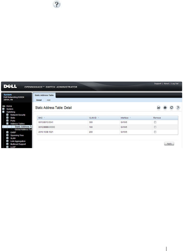
Managing the MAC Address Table 1017
Managing the MAC Address Table (Web)
This section provides information about the OpenManage Switch
Administrator pages to use to manage the MAC address table on a Dell
Networking N2000, N3000, and N4000 series switches. For details about the
fields on a page, click at the top of the page.
Static Address Table
Use the Static Address Table page to view MAC addresses that have been
manually added to the MAC address table and to configure static MAC
addresses.
To display the Static Address Table page, click Switching
→
Address Tables
→
Static Address Table in the navigation panel.
Figure 30-1. Static MAC Address
Adding a Static MAC Address
To add a static MAC address:
1
Open the
Static MAC Address
page
.
2
Click
Add
.
The
Add Static MAC Address
page displays.

1018 Managing the MAC Address Table
Figure 30-2. Adding Static MAC Address
3
Select the interface to associate with the static address.
4
Specify the MAC address and an associated VLAN ID.
5
Click
Apply
.
The new static address is added to the
Static MAC Address Table
, and the
device is updated.

Managing the MAC Address Table 1019
Global Address Table
The Global Address Table page contains fields for querying information in
the dynamic address table, including the interface type, MAC addresses,
VLAN, and table sorting key. Packets forwarded to an address stored in the
address table are forwarded directly to those ports.
The Global Address Table also contains information about the aging time
before a dynamic MAC address is removed from the table.
To display the Global Address Table, click Switching
→
Address Tables
→
Global Address Table in the navigation panel.
Figure 30-3. Global Address Table

1020 Managing the MAC Address Table
Managing the MAC Address Table (CLI)
This section provides information about the commands you use to manage
the MAC address table on the switch. For more information about the
commands, see the
Dell Networking N2000, N3000, and N4000 Series
Switches CLI Reference Guide
at support.dell.com/manuals.
Managing the MAC Address Table
Beginning in Privileged EXEC mode, use the following commands to add a
static MAC address to the table, control the aging time for dynamic
addresses, and view entries in the MAC address table.
Command Purpose
configure Enter global configuration mode.
mac address-table static
mac-address
vlan
vlan-id
interface
interface
Add a static MAC source address to the MAC address table.
•
mac-address
— A valid MAC address in the format
xxxx.xxxx.xxxx.
•
vlan-id —
A valid VLAN.
•
interface —
A valid port or LAG, including the interface
type and number.
mac address-table
aging-time {0 | 10-
1000000}
Specify the number of seconds that must pass before an
unused dynamically-learned MAC address is removed from
the MAC address table. A value of 0 disables the aging time
for the MAC address table.
exit Exit to Privileged EXEC mode.
show mac address-table
[static | dynamic]
View information about the entries in the MAC address
table. Use the keywords static or dynamic to specify the
address type to view.
For dynamic entries, you can use the clear mac address-
table command to remove entries from the table.
show mac address-table
{vlan
vlan
| interface
interface
[vlan
vlan-id
]}
View information about the MAC addresses that have been
configured or learned on the switch, a specific VLAN, or an
interface (Ethernet port or LAG/port-channel).
show mac address-table
count [{vlan
vlan-id
|interface
interface
}]
View information about the number of addresses that have
been configured or learned on the switch, a specific VLAN,
or an interface (Ethernet port or LAG/port-channel).

Configuring Routing Interfaces 1021
31
Configuring Routing Interfaces
This chapter describes the routing (layer 3) interfaces the Dell Networking
series switches support, which includes VLAN routing interfaces, loopback
interfaces, and tunnel interfaces.
The topics covered in this chapter are:
• Routing Interface Overview
• Default Routing Interface Values
• Configuring Routing Interfaces (Web)
• Configuring Routing Interfaces (CLI)
For information about configuring IPv6 characteristics on routing interfaces,
see "Configuring IPv6 Routing" on page 1241.
For configuration examples that configure VLAN routing interfaces, see "IP
Routing Configuration Example" on page 1084 in the Configuring IP Routing
chapter. For a configuration example that includes tunnel and loopback
interface creation, see "Interconnecting an IPv4 Backbone and Local IPv6
Network" on page 1187.
Routing Interface Overview
Routing interfaces are logical interfaces that can be configured with an IP
address. Routing interfaces provide a means of transmitting IP packets
between subnets on the network.
What Are VLAN Routing Interfaces?
VLANs divide a single physical network (broadcast domain) into separate
logical networks. To forward traffic across VLAN boundaries, a layer 3 device,
such as router, is required. Dell Networking series switches can act as layer 3
devices when you configure VLAN routing interfaces. VLAN routing
interfaces make it possible to transmit traffic between VLANs while still
containing broadcast traffic within VLAN boundaries. The configuration of
VLAN routing interfaces makes inter-VLAN routing possible.

1022 Configuring Routing Interfaces
For each VLAN routing interface you can assign a static IP address, or you can
allow a network DHCP server to assign a dynamic IP address.
When a port is enabled for bridging (L2 switching) rather than routing,
which is the default, all normal bridge processing is performed for an inbound
packet, which is then associated with a VLAN. Its MAC Destination Address
(MAC DA) and VLAN ID are used to search the MAC address table. If
routing is enabled for the VLAN, and the MAC DA of an inbound unicast
packet is that of the internal router interface, the packet is routed. An
inbound multicast packet is forwarded to all ports in the VLAN, plus the
internal bridge-router interface, if it was received on a routed VLAN.
Since a port can be configured to belong to more than one VLAN, VLAN
routing might be enabled for all of the VLANs on the port or for only some of
the VLANs on the port. VLAN Routing can be used to allow more than one
physical port to reside on the same subnet. It could also be used when a
VLAN spans multiple physical networks, or when additional segmentation or
security is required.
What Are Loopback Interfaces?
A loopback interface is a logical interface that is always up and, because it
cannot go down, allows the switch to have a stable IP address that other
network devices and protocols can use to reach the switch. The loopback can
provide the source address for sent packets.
The loopback interface does not behave like a network switching port.
Specifically, there are no neighbors on a loopback interface; it is a pseudo-
device for assigning local addresses so that the other layer 3 devices can
communicate with the switch by using the loopback IP address. The loopback
interface is always up and can receive traffic from any of the existing active
interfaces. Thus, given reachability from a remote client, the address of the
loopback can be used to communicate with the switch through various
services such as Telnet and SSH. In this way, the IP address on a loopback
behaves identically to any of the local addresses of the VLAN routing
interfaces in terms of the processing of incoming packets.
NOTE: In this context, loopback interfaces should not be confused with the
loopback IP address, usually 127.0.0.1, assigned to a host for handling self-routed
packets.

Configuring Routing Interfaces 1023
What Are Tunnel Interfaces?
Tunnels are a mechanism for transporting a packet across a network so that it
can be evaluated at a remote location or
tunnel endpoint
. The tunnel,
effectively, hides the packet from the network used to transport the packet to
the endpoint. This allows for the transmission of packets that the transport
network cannot process directly, such as in one of the following cases:
• The packet protocol is not supported.
• The packet is in an incompatible addressing space.
• The packet is encrypted.
Dell Networking series switches support tunnels to encapsulate IPv6 traffic in
IPv4 tunnels to provide functionality to facilitate the transition of IPv4
networks to IPv6 networks.
The switch supports two types of tunnels: configured (6-in-4) and automatic
(6-to-4). Configured tunnels have an explicit configured endpoint and are
considered to be point-to-point interfaces. Automatic tunnels determine the
endpoint of the tunnel from the destination address of packets routed into
the tunnel. These tunnels correspond to Non-Broadcast Multi-Access
(NBMA) interfaces. A configured tunnel interface has a single tunnel
associated with it, while an automatic tunnel interface has an infinite number
of tunnels (limited only by the address encoding scheme).
Because tunnels are used as logical interfaces, you can define static routes
that reference the tunnels. Additionally, dynamic routing can be configured to
use the tunnels.
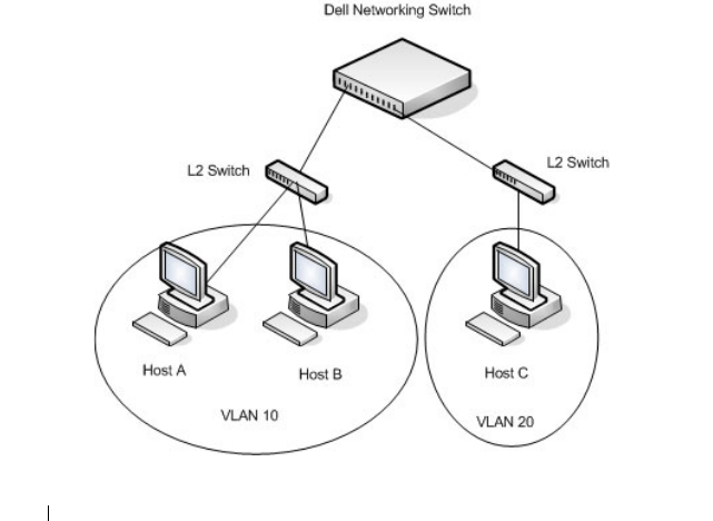
1024 Configuring Routing Interfaces
Why Are Routing Interfaces Needed?
The routing interfaces this chapter describes have very different applications
and uses, as this section describes. If you use the switch as a layer 2 device
that handles switching only, routing interface configuration is not required.
When the switch is used as a layer 2 device, it typically connects to an
external layer 3 device that handles the routing functions.
VLAN Routing
VLAN routing is required when the switch is used as a layer 3 device. VLAN
routing must be configured to allow the switch to forward IP traffic between
subnets and allow hosts in different networks to communicate.
In Figure 31-1 the Dell Networking switch is configured as an L3 device and
performs the routing functions for hosts connected to the L2 switches. For
Host A to communicate with Host B, no routing is necessary. These hosts are
in the same VLAN. However, for Host A in VLAN 10 to communicate with
Host C in VLAN 20, the Dell Networking switch must perform inter-VLAN
routing.
Figure 31-1. Inter-VLAN Routing

Configuring Routing Interfaces 1025
Loopback Interfaces
When packets are sent to the loopback IP address, the network should be able
to deliver the packets as long as any physical interface on the switch is up.
There are many cases where you need to send traffic to a switch, such as in
switch management. The loopback interface IP address is a good choice for
communicating with the switch in these cases because the loopback interface
cannot go down when the switch is powered on and operational.
Tunnel Interface
Tunnels can be used in networks that support both IPv6 and IPv4. The tunnel
allows non-contiguous IPv6 networks to be connected over an IPv4
infrastructure.

1026 Configuring Routing Interfaces
Default Routing Interface Values
By default, no routing interfaces are configured.
When you create a VLAN, no IP address is configured, and DHCP is disabled.
After you configure an IP address on a VLAN or loopback interface, the VLAN
interface is available for L3 routing (if enabled) and is capable of resolved
ARPs and responding to pings, and the interface has the default configuration
shown in Table 31-1.
Most interface configuration parameters are not applicable to loopback
interfaces, so you cannot change the default values. However, when you create
a loopback interface, the default values are similar to those of VLAN routing
interfaces, as Table 31-1 shows.
When you create a tunnel, it has the default values shown in Table 31-2
Table 31-1. VLAN Routing Interface and Loopback Interface Defaults
Parameter Default Value
Forward Net Directed Broadcasts Disabled
Encapsulation Type Ethernet (N/A for loopbacks)
Proxy Arp Enabled
Local Proxy Arp Disabled
IP MTU 1500
Bandwidth Not configured.
Destination Unreachables Enabled
ICMP Redirects Enabled
Table 31-2. Tunnel Interface Defaults
Parameter Default Value
Tunnel mode 6-in-4 configured
Link Local Only Mode Disabled
Source address None
Destination address 0.0.0.0
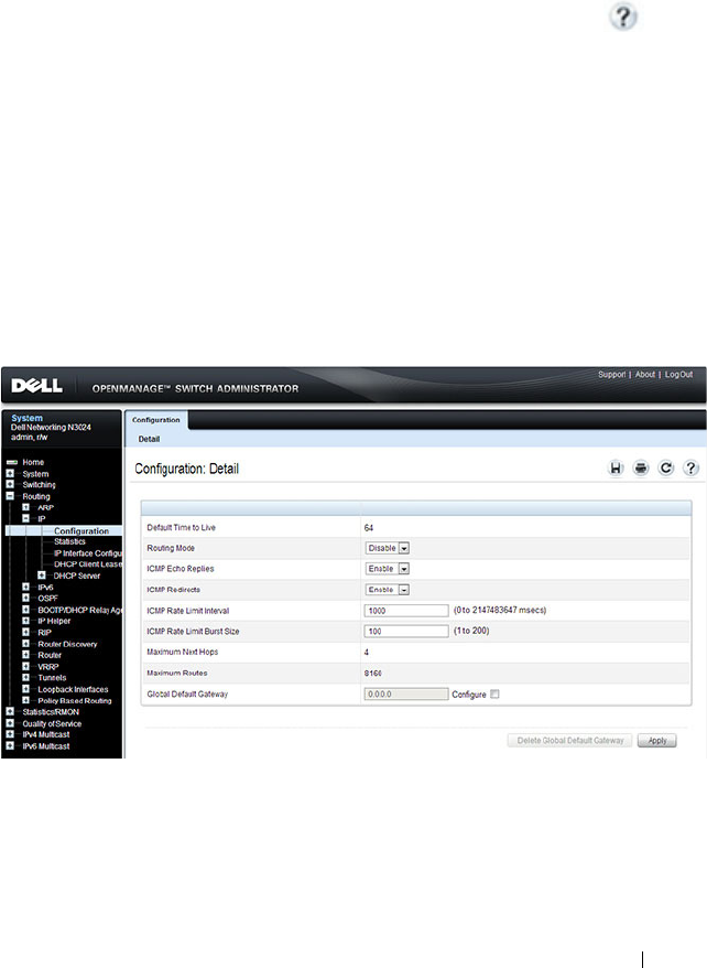
Configuring Routing Interfaces 1027
Configuring Routing Interfaces (Web)
This section provides information about the OpenManage Switch
Administrator pages for configuring and monitoring VLAN routing interfaces,
loopback interfaces, and tunnels on a Dell Networking N2000, N3000, and
N4000 series switches. For details about the fields on a page, click at the
top of the page.
IP Interface Configuration
Use the IP Interface Configuration
page to update IP interface data for this
switch. The IP interface configuration includes the ability to configure the
bandwidth, Destination Unreachable messages, and ICMP Redirect
messages.
To display the page, click Routing
→
IP
→
IP Interface Configuration in the
navigation panel.
Figure 31-2. IP Interface Configuration
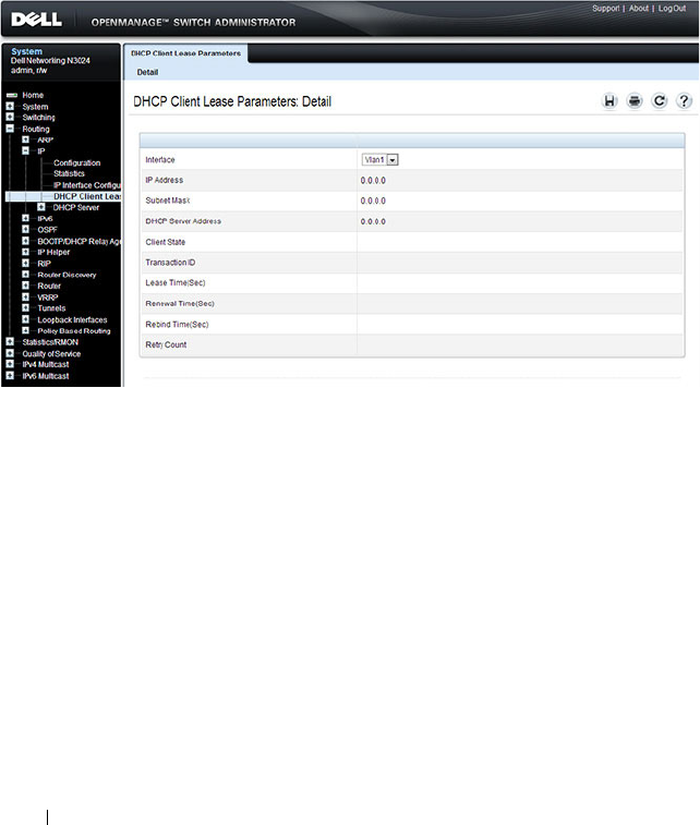
1028 Configuring Routing Interfaces
DHCP Lease Parameters
Use the DHCP Lease Parameters
page to view information about the
network information automatically assigned to an interface by the DHCP
server.
To display the page, click Routing
→
IP
→
DHCP Lease Parameters in the
navigation panel.
Figure 31-3. DHCP Lease Parameters
VLAN Routing Summary
Use the VLAN Routing Summary page to view summary information about
VLAN routing interfaces configured on the switch.
To display the page, click Routing
→
VLAN Routing
→
Summary in the
navigation panel.
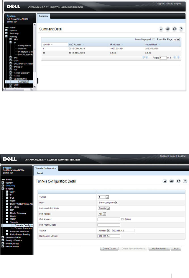
Configuring Routing Interfaces 1029
Figure 31-4. VLAN Routing Summary
Tunnel Configuration
Use the Tunnels Configuration
page to create, configure, or delete a tunnel.
To display the page, click Routing
→
Tun nels
→
Configuration in the
navigation panel.
Figure 31-5. Tunnel Configuration
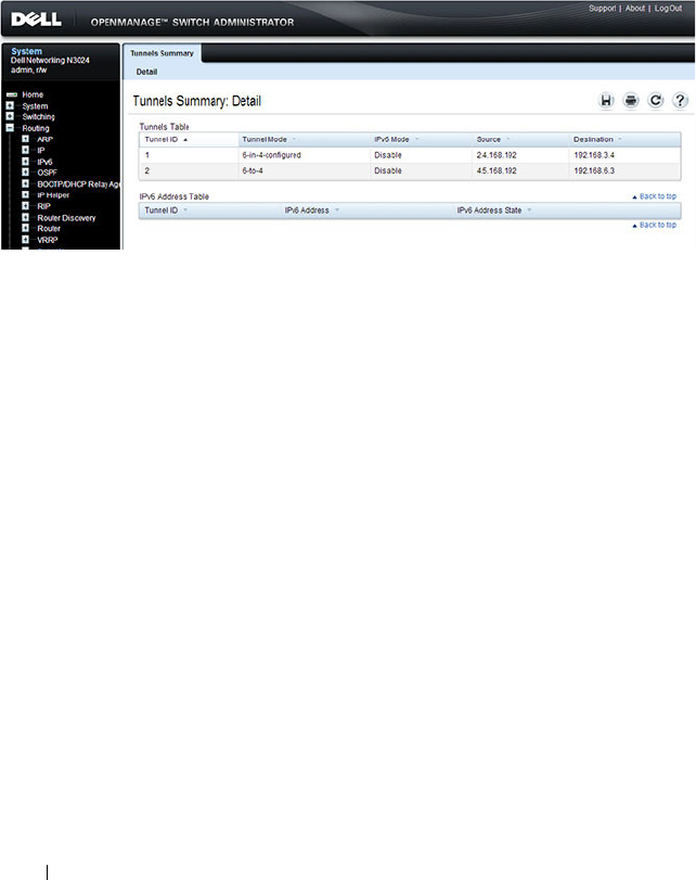
1030 Configuring Routing Interfaces
Tunnels Summary
Use the Tunnels Summary
page to display a summary of configured tunnels.
To display the page, click Routing
→
Tunn els
→
Summary in the navigation
panel.
Figure 31-6. Tunnels Summary
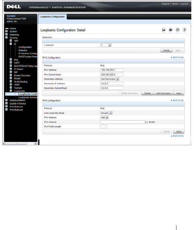
Configuring Routing Interfaces 1031
Loopbacks Configuration
Use the Loopbacks Configuration
page to create, configure, or remove
loopback interfaces. You can also set up or delete a secondary address for a
loopback.
To display the page, click Routing
→
Loopback Interfaces
→
Loopback
Interfaces Configuration in the navigation panel.
Figure 31-7. Loopback Configuration
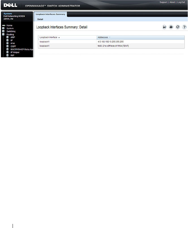
1032 Configuring Routing Interfaces
Loopbacks Summary
Use the Loopbacks Summary
page to display a summary of configured
loopback interfaces on the switch.
To display the page, click Routing
→
Loopback Interfaces
→
Loopback
Interfaces Summary in the navigation panel.
Figure 31-8. Loopbacks Summary

Configuring Routing Interfaces 1033
Configuring Routing Interfaces (CLI)
This section provides information about the commands you use to configure
VLAN routing interfaces, loopbacks, and tunnels on the switch. For more
information about the commands, see the
Dell Networking N2000, N3000,
and N4000 Series Switches CLI Reference Guide
at
support.dell.com/manuals.
Configuring VLAN Routing Interfaces (IPv4)
Beginning in Privileged EXEC mode, use the following commands to
configure a VLAN as a routing interface and set the IP configuration
parameters.
Command Purpose
configure Enter Global Configuration mode.
interface vlan
vlan-id
Enter Interface Configuration mode for the specified
VLAN.
ip address {dhcp | none
|
ip_address subnet_mask
[secondary]}
Configure the IP address.
Use the dhcp keyword to enable the DHCP client and
obtain an IP address from a network DHCP server. Use
none to release the address obtained from the DHCP
server.
Use
ip_address
and
subnet_mask
to assign a static IP
address. If you configure a static address, you can use
the secondary keyword to specify that the address is a
secondary IP address.
ip netdirbcast Enable the forwarding of network-directed broadcasts.
encapsulation {ethernet |
snap}
Configure the link-layer encapsulation type for the
packet. Routed frames are always ethernet encapsulated
when a frame is routed to a VLAN.
ip proxy-arp Enable proxy ARP on the interface. Without proxy ARP,
the switch responds to an ARP request only if the target
IP address is an address configured on the interface
where the ARP request arrived. This command is not
available in interface range mode.

1034 Configuring Routing Interfaces
ip local-proxy-arp Enable local proxy ARP on the interface to allow the
switch to respond to ARP requests for hosts on the same
subnet as the ARP source.
bandwidth
size
Set the configured bandwidth on this interface to
communicate the speed of the interface to higher level
protocols. OSPF uses the bandwidth value to compute
link cost. The range is 1–10000000.
ip unreachables Allow the switch to send ICMP Destination
Unreachable messages in response to packets received
on the interface.
ip redirects Allow the switch to send ICMP Redirect messages in
response to packets received on the interface.
exit Exit to Global Config mode.
ip default-gateway
ip_address
Configure the default gateway. All switch interfaces use
the same default gateway.
exit Exit to Privileged EXEC mode.
show dhcp lease [interface
interface
]
View information about the DHCP leases acquired for
all interfaces or for the specified interface.
For a VLAN, the
interface_string
parameter is vlan
followed by the VLAN ID, with no space, for example
vlan10.
show ip interface vlan
vlan-
id
View the IP interface configuration information for the
specified routing VLAN.
Command Purpose

Configuring Routing Interfaces 1035
Configuring Loopback Interfaces
Beginning in Privileged EXEC mode, use the following commands to
configure a loopback interface.
Command Purpose
configure Enter Global Configuration mode.
interface loopback
loopback-id
Create the loopback interface and enter Interface
Configuration mode for the specified loopback
interface.
ip address
ip_address
subnet_mask
[secondary]
Configure a static IP address and subnet mask. Use the
secondary keyword to specify that the address is a
secondary IP address.
CTRL + Z Exit to Privileged EXEC mode.
show ip interface loopback
loopback-id
View interface configuration information for the
specified loopback interface.

1036 Configuring Routing Interfaces
Configuring Tunnels
Beginning in Privileged EXEC mode, use the following commands to
configure a loopback interface.
NOTE: For information about configuring the IPv6 interface characteristics for a
tunnel, see "Configuring IPv6 Routing" on page 1241.
Command Purpose
configure Enter Global Configuration mode.
interface tunnel
tunnel-id
Create the tunnel interface and enter Interface
Configuration mode for the specified tunnel.
tunnel mode ipv6ip [6to4] Specify the mode of the tunnel. If you use the 6to4
keyword, the tunnel is an automatic tunnel. If you omit
the keyword, the tunnel is a point-to-point (configured)
tunnel.
ipv6 enable Enable IPv6 on this interface using the Link Local
address.
tunnel source {
ipv4addr
|
vlan
vlan-id
}
Specify the source transport address of the tunnel,
either, which can be an IPv4 address or a VLAN routing
interface.
tunnel destination
ipv4addr
Specify the destination transport IPv4 address of the
tunnel.
CTRL + Z Exit to Privileged EXEC mode.
show interfaces tunnel
[
tunnel-id
]
View configuration information for all tunnels or for the
specified tunnel.

Configuring DHCP Server and Relay Settings 1037
32
Configuring DHCP Server and Relay
Settings
This chapter describes how to configure the switch to dynamically assign
network information to hosts by using the Dynamic Host Configuration
Protocol (DHCP).
The topics covered in this chapter include:
• DHCP Overview
• Default DHCP Server Values
• Configuring the DHCP Server (Web)
• Configuring the DHCP Server (CLI)
• DHCP Server Configuration Examples
DHCP Overview
DHCP is generally used between clients and servers for the purpose of
assigning IP addresses, gateways, and other network settings such as DNS and
SNTP server information.
DHCP Snooping is a security feature that monitors DHCP messages between
a DHCP client and DHCP server. It filters harmful DHCP messages and
builds a bindings database of (MAC address, IP address, VLAN ID, port)
tuples that are specified as authorized. DHCP snooping can be enabled
globally and on specific VLANs. For information about DHCP Snooping, see
"Snooping and Inspecting Traffic" on page 879.
Dell Networking switches support a DHCP client for obtaining the switch
address from the network, an IPv4 DHCP server for serving IPv4 addresses to
DHCP clients in the network, L2 and L3 DHCP relay for relaying IPv4
address assignments from network-based DHCP servers to clients in the same
or different subnets, and DHCP snooping for protecting the switch and
DHCP clients from certain security risks.
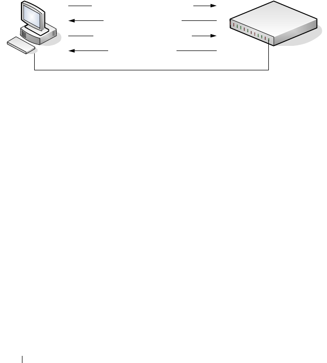
1038 Configuring DHCP Server and Relay Settings
How Does DHCP Work?
When a host connects to the network, the host’s DHCP client broadcasts a
message requesting information from any DHCP server that receives the
broadcast. One or more DHCP servers respond to the request. The response
includes the requested information, such as the IP address, subnet mask, and
default gateway IP address. The client accepts an offer from one of the
servers, and the server sends an acknowledgment to the client to confirm the
transaction.
Figure 32-1. Message Exchange Between DHCP Client and Server
The DHCP server maintains one or more set of IP addresses the and other
configuration information available, by request, to DHCP clients. Each set of
information is known as an address pool.
After a client leases an IP address from the DHCP server, the server adds an
entry to its database. The entry is called a binding.
What are DHCP Options?
DHCP options are collections of data with type codes that indicate how the
options should be used. Options can specify information that is required for
the DHCP protocol, IP stack configuration parameters for the client,
information allowing the client to rendezvous with DHCP servers, and so on.
When a client broadcasts a request for information, the request includes the
option codes that correspond to the information the client wants the DHCP
server to supply. The Web pages and CLI commands to configure DHCP
server settings include many predefined options for the information that is
most commonly requested by DHCP clients. For example, DHCP client
`
DHCPDISCOVER (broadcast)
DHCPOFFER (unicast)
DHCPREQUEST (broadcast)
DHCPACK (unicast)
DHCP Client DHCP Server
(Dell Networking Switch)

Configuring DHCP Server and Relay Settings 1039
discover requests typically include options for the IP address (option 50),
subnet mask (option 1), default gateway (option 3), and DNS server (option
6). These options are predefined.
For options that are not predefined, you can enter the option code and specify
the data type along with the data that the switch should include in DHCP
offers. RFC2132 specifies many of the DHCP options. Additional options are
described in later RFCs.
How is DHCP Option 82 Used?
The Dell Networking Operating System (DNOS) supports insertion of
DHCP Option 82 information into DHCP messages relayed to DHCP
servers. The Dell Networking switch can be configured to insert either the
Circuit ID or the Remote ID or both. When enabled, the Circuit ID contains
the port identifier over which the DHCP request was received. The Remote
ID is configurable by the administrator on a per-switch basis.
Consider a network with multiple DHCP servers, where the administrator
wishes to serve addresses from a specific server based on the switch and port
to which the user station is connected. User traffic is served on VLAN 10 or
20.
The administrator globally enables DHCP relay and configures DHCP relay
on the end-user ports of each switch as follows:
console(config)#dhcp l2relay
console(config)#interface range gi1/0/1-24
console(config-if)#dhcp l2relay
console(config-if)#exit
Then, the administrator configures the remote-id and circuit-id:
console(config)#dhcp l2relay circuit-id vlan 10,20
console(config)# dhcp l2relay remote-id "Switch A" vlan 10,20
Finally, the administrator configures the uplink for DHCP relay and sets the
interface to trust Option 82 information received on the interface:
console(config)#dhcp l2relay
console(config)#interface range te1/0/1
console(config-if)#dhcp l2relay
console(config-if)#dhcp l2relay trust
console(config-if)#exit

1040 Configuring DHCP Server and Relay Settings
The administrator is using a Microsoft DHCP server. Microsoft DHCP servers
do not have native support for DHCP Option 82, but it can be added using
the DhcpServerCalloutEntry API to retrieve the information via the
DhcpHandleOptionsHook configured on the switches. Adding Option 82
support enables choosing whether or not a particular DHCP server should
respond to the DHCP request, and whether it should only respond to requests
from a particular switch (as identified by the remote-id) and port (as
identified by the circuit-id). For further information and an example, follow
this web link:
http://blogs.technet.com/b/teamdhcp/archive/2009/07/06/dhcp-server-callout-
api-usage.aspx
For Linux-based systems, which natively support option 82, a configuration to
serve two private pools (Pool1 and Pool2) and one public pool of DHCP
addresses based upon the remote-id and circuit-id might look like the
following:
dhcpd.conf file:
class "Pool1" {
match option agent.remote-id;
match option agent.circuit-id;
}
subclass "Pool1" "Switch A" "Gi1/0/1";
subclass "Pool1" "Switch A" "Gi1/0/2";
subclass "Pool1" "Switch A" "Gi1/0/3";
class "Pool2" {
match option agent.remote-id;
match option agent.circuit-id;
}
subclass "Pool2" "Switch B" "Gi1/0/1";
subclass "Pool2" "Switch B" "Gi1/0/2";
subclass "Pool2" "Switch B" "Gi1/0/3";
shared-network Public {
subnet 10.1.222.0 netmask 255.255.254.0 {
pool {
deny members of "Pool1";
deny members of "Pool2";
option routers 10.1.222.1;

Configuring DHCP Server and Relay Settings 1041
option subnet-mask 255.255.254.0;
option domain-name-servers 10.1.218.3, 10.1.219.3;
range dynamic-bootp 10.1.222.3 10.1.222.254;
range dynamic-bootp 10.1.223.3 10.1.223.254;
default-lease-time 21600;
max-lease-time 43200;
}
}
subnet 10.2.109.192 netmask 255.255.255.224 {
pool {
allow members of "Pool1";
range 10.2.109.194 10.2.109.222;
option routers 10.2.109.193;
option subnet-mask 255.255.255.224;
option domain-name-servers 10.1.218.3,10.1.219.3;
default-lease-time 21600;
max-lease-time 43200;
}
}
subnet 10.2.109.224 netmask 255.255.255.224 {
pool {
allow members of "Pool2";
range 10.2.109.226 10.2.109.254;
option routers 10.2.109.225;
option subnet-mask 255.255.255.224;
option domain-name-servers 10.1.218.3,10.1.219.3;
default-lease-time 21600;
max-lease-time 43200;
}
}
}
}
What Additional DHCP Features Does the Switch Support?
The switch software includes a DHCP client that can request network
information from a DHCP server on the network during the initial system
configuration process. For information about enabling the DHCP client, see
"Setting the IP Address and Other Basic Network Information" on page 147.
If the switch is functioning as a Layer 3 device, the Layer 3 DHCP Relay
Agent can relay DHCP messages between DHCP clients and DHCP servers
that are located in different IP subnets.

1042 Configuring DHCP Server and Relay Settings
The DHCP Layer 2 Relay feature permits Layer 3 Relay agent functionality in
Layer 2 switched networks. The switch supports L2 DHCP relay
configuration on individual ports, link aggregation groups (LAGs) and
VLANs. For information about Layer 2 and Layer 3 DHCP Relay, see
"Configuring L2 and L3 Relay Features" on page 1087.
Default DHCP Server Values
By default, the DHCP server is disabled, and no address pools are configured.
You must create at least one address pool and enable the DHCP server to
allow the switch to dynamically assign network information to hosts with
DHCP clients that broadcast requests.
The DHCP server can lease a maximum of 256 addresses.
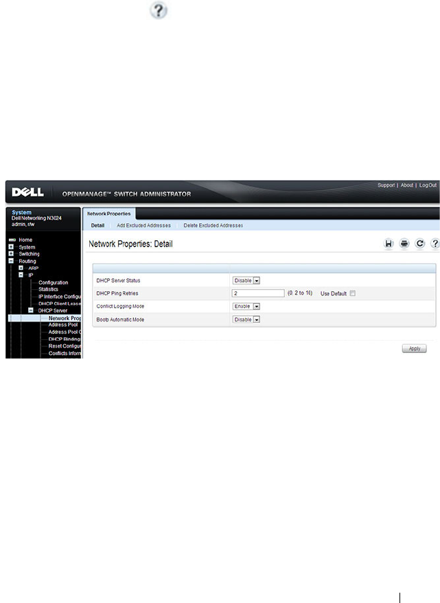
Configuring DHCP Server and Relay Settings 1043
Configuring the DHCP Server (Web)
This section provides information about the OpenManage Switch
Administrator pages for configuring and monitoring the DHCP server on a
Dell Networking N2000, N3000, and N4000 series switches. For details about
the fields on a page, click at the top of the page.
DHCP Server Network Properties
Use the
Network Properties page to define global DHCP server settings and
to configure addresses that are not included in any address pools.
To display the Network Properties page, click Routing
→
IP
→
DHCP Server
→
Network Properties in the navigation panel.
Figure 32-2. DHCP Server Network Properties
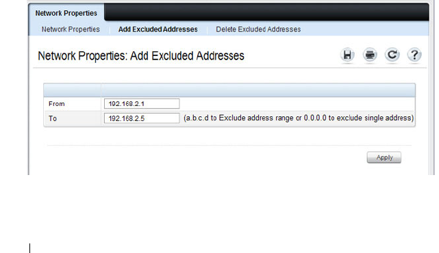
1044 Configuring DHCP Server and Relay Settings
Adding Excluded Addresses
To exclude an address:
1
Open the
Network Properties
page.
2
Click
Add
Excluded Addresses
to display the
Add Excluded Addresses
page.
3
In the From field, enter the first IP address to exclude from any configured
address pool.
4
If the address in the From field is the only address to exclude, or if the
excluded addresses are non-contiguous, leave the To field as the default
value of 0.0.0.0. Otherwise, enter the last IP address to excluded from a
contiguous range of IP addresses.
In Figure 32-3, the From field contains the IP address 192.168.2.1, and the
To field contains the IP address 192.168.2.5. This means that the following
IP addresses are not available for lease:
• 192.168.2.1
• 192.168.2.2
• 192.168.2.3
• 192.168.2.4
• 192.168.2.5
Figure 32-3. Add Excluded Addresses
5
Click
Apply
.
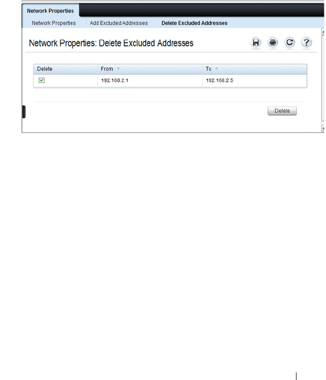
Configuring DHCP Server and Relay Settings 1045
Deleting Excluded Addresses
To remove an excluded address:
1
Open the
Network Properties
page.
2
Click
Delete
Excluded Addresses
to display the
Delete Excluded
Addresses
page.
3
Select the check box next to the address or address range to delete.
Figure 32-4. Delete Excluded Addresses
4
Click
Apply
.
Address Pool
Use the
Address Pool page to create the pools of IP addresses and other
network information that can be assigned by the server.
To display the Address Pool page, click Routing
→
IP
→
DHCP Server
→
Address Pool in the navigation panel.
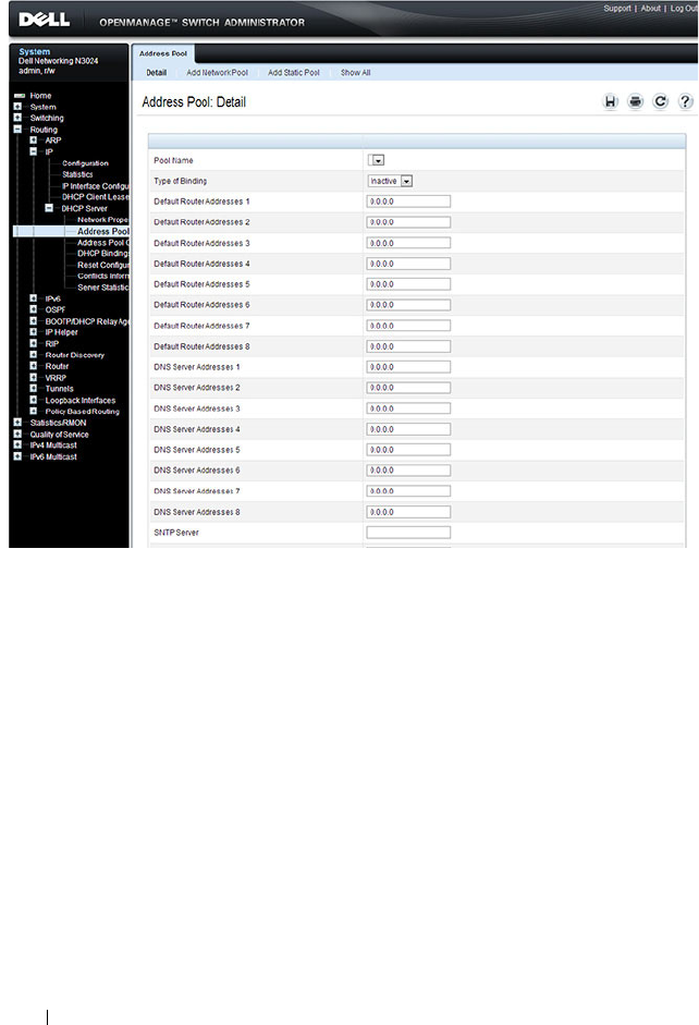
1046 Configuring DHCP Server and Relay Settings
Figure 32-5. Address Pool
Adding a Network Pool
To create and configure a network pool:
1
Open the
Address Pool
page.
2
Click
Add
Network Pool
to display the
Add Network Pool
page.
3
Assign a name to the pool and complete the desired fields.
In Figure 32-6, the network pool name is Engineering, and the address
pool contains all IP addresses in the 192.168.5.0 subnet, which means a
client that receives an address from the DHCP server might lease an
address in the range of 192.168.5.1 to 192.168.5.254.
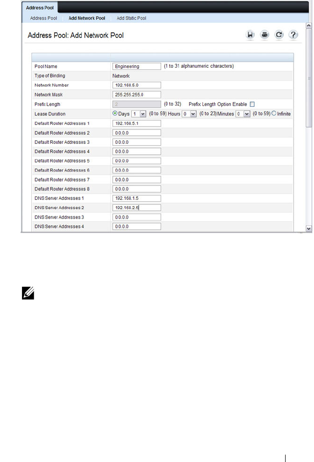
Configuring DHCP Server and Relay Settings 1047
Figure 32-6. Add Network Pool
The Engineering pool also configures clients to use 192.168.5.1 as the
default gateway IP address and 192.168.1.5 and 192.168.2.5 as the primary
and secondary DNS servers.
4
Click
Apply
.
Adding a Static Pool
To create and configure a static pool of IP addresses:
1
Open the
Address Pool
page.
2
Click
Add
Static Pool
to display the
Add Static Pool
page.
3
Assign a name to the pool and complete the desired fields.
NOTE: The IP address 192.168.5.1 should be added to the global list of
excluded addresses so that it is not leased to a client.
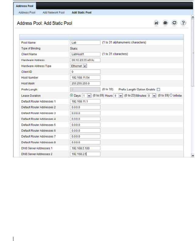
1048 Configuring DHCP Server and Relay Settings
In Figure 32-7, the Static pool name is Lab, and the name of the client in
the pool is LabHost1. The client’s MAC address is mapped to the IP
address 192.168.11.54, the default gateway is 192.168.11.1, and the DNS
servers the client will use have IP addresses of 192.168.5.100 and
192.168.2.5.
Figure 32-7. Add Static Pool
4
Click
Apply
.
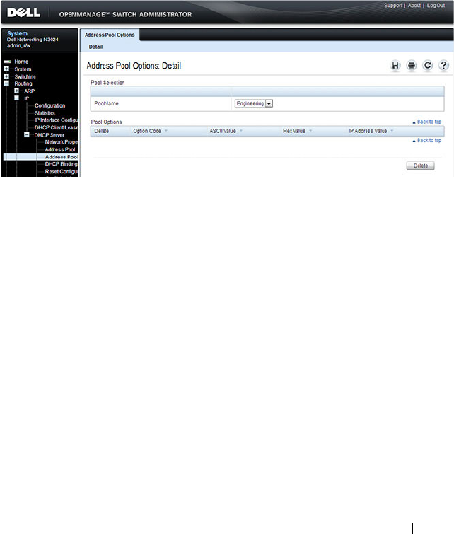
Configuring DHCP Server and Relay Settings 1049
Address Pool Options
Use the
Address Pool Options page to view manually configured options. You
can define options when you create an address pool, or you can add options to
an existing address pool.
To display the Address Pool Options page, click Routing
→
IP
→
DHCP
Server
→
Address Pool Options in the navigation panel.
Figure 32-8. Address Pool Options
Defining DHCP Options
To configure DHCP options:
1
Open the
Address Pool
page.
2
Select the
Add
Options
check box.
3
Select the check box that corresponds to the value type (ASCII,
Hexadecimal, or IP address).
4
Specify the value(s) in the corresponding field.
Figure 32-9 shows an example of adding the SMTP server IP address. The
option code for the SMTP server is 69, and the IP address of the SMTP
server is 192.168.10.15.
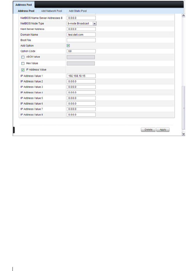
1050 Configuring DHCP Server and Relay Settings
Figure 32-9. Add DHCP Option
5
Click
Apply
.
6
To verify that the option has been added to the address pool, open the
Address Pool Options
page.
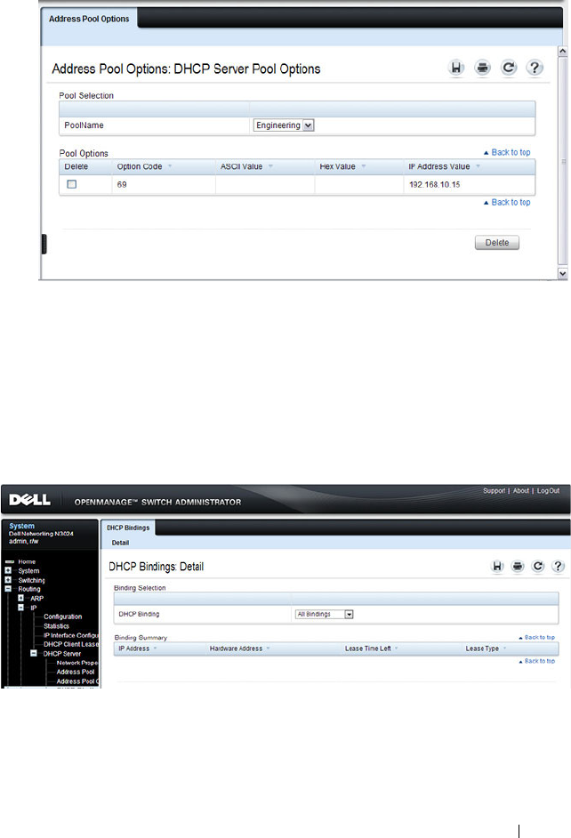
Configuring DHCP Server and Relay Settings 1051
Figure 32-10. View Address Pool Options
DHCP Bindings
Use the
DHCP Bindings page to view information about the clients that
have leased IP addresses from the DHCP server.
To display the DHCP Bindings page, click Routing
→
IP
→
DHCP Server
→
DHCP Bindings in the navigation panel.
Figure 32-11. DHCP Bindings
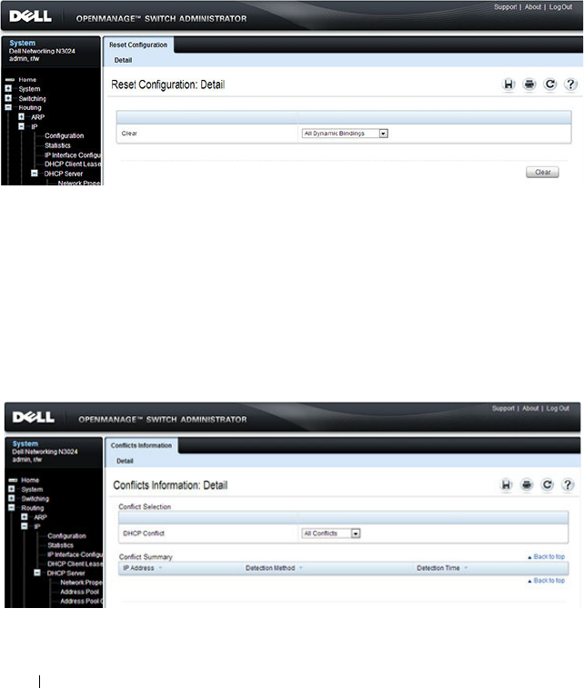
1052 Configuring DHCP Server and Relay Settings
DHCP Server Reset Configuration
Use the
Reset Configuration page to clear the client bindings for one or more
clients. You can also reset bindings for clients that have leased an IP address
that is already in use on the network.
To display the Reset Configuration page, click Routing
→
IP
→
DHCP
Server
→
Reset Configuration in the navigation panel.
Figure 32-12. Reset DHCP Bindings
DHCP Server Conflicts Information
Use the
Conflicts Information
page to view information about clients that
have leased an IP address that is already in use on the network.
To display the
Conflicts Information
page, click Routing
→
IP
→
DHCP
Server
→
Conflicts Information
in the navigation panel.
Figure 32-13. DHCP Server Conflicts Information
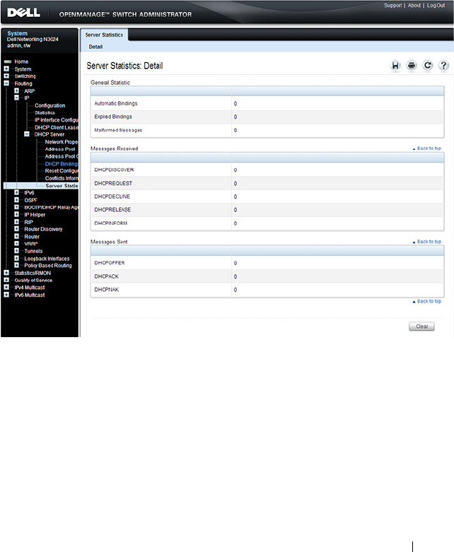
Configuring DHCP Server and Relay Settings 1053
DHCP Server Statistics
Use the
Server Statistics
page to view general DHCP server statistics,
messages received from DHCP clients, and messages sent to DHCP clients.
To display the
Server Statistics
page, click Routing
→
IP
→
DHCP Server
→
Server Statistics
in the navigation panel.
Figure 32-14. DHCP Server Statistics

1054 Configuring DHCP Server and Relay Settings
Configuring the DHCP Server (CLI)
This section provides information about the commands you use to configure
and monitor the DHCP server and address pools. For more information about
the commands, see the
Dell Networking N2000, N3000, and N4000 Series
Switches CLI Reference Guide
at support.dell.com/manuals.
Configuring Global DHCP Server Settings
Beginning in Privileged EXEC mode, use the following commands to
configure settings for the DHCP server.
Command Purpose
configure Enter Global Configuration mode.
service dhcp Enable the DHCP server.
ip dhcp ping packets Specify the number, in a range from 2-10, of packets a
DHCP server sends to a pool address as part of a ping
operation.
ip dhcp conflict logging Enable conflict logging on DHCP server
ip dhcp bootp
automatic
Enable the allocation of the addresses to the BootP client.
ip dhcp excluded-
address
lowaddress
[
highaddress
]
Specify the IP addresses that a DHCP server should not
assign to DHCP clients. You can specify a single IP
address, or you can specify a contiguous range by using
both the low-address and high-address variables.
exit Exit to Privileged EXEC mode.
show ip dhcp global
configuration
Verify the global DHCP server configuration.

Configuring DHCP Server and Relay Settings 1055
Configuring a Dynamic Address Pool
Beginning in Privileged EXEC mode, use the following commands to create
an address pool with network information that is dynamically assigned to
hosts with DHCP clients that request the information.
Command Purpose
configure Enter Global Configuration mode.
ip dhcp pool
name
Create a DHCP address pool and enters DHCP pool
configuration mode.
network
network-ip
[
mask
|
prefixlength
]
Configure the subnet number and mask for a DHCP
address pool. Clients requesting an IP address can be
assigned any non-excluded IP address within this network.
lease [
duration
] |
infinite}]
Specify the duration of the lease for an IP address that is
assigned from a DHCP server to a DHCP client.
•
duration
— Days the lease is valid. You can optionally
specify the hours and minutes after specifying the days.
•
infinite
— 60 day lease
default-router
address1
[
address2....address8
]
Specify the list of default gateway IP addresses to be
assigned to the DHCP client.
dns-server
address1
[
address2....address8
]
Specify the list of DNS server IP addresses to be assigned
to the DHCP client.
domain-name
domain
Specify the domain name for a DHCP client.
option
code
{ascii
string
| hex
string1
[
string2...string8
] | ip
address1
[
address2...address8
]}
Manually configure DHCP options.
CTRL + Z Exit to Privileged EXEC mode.
show ip dhcp pool
configuration {
name
|
all}
View the settings for the specified address pool or for all
configured address pools.

1056 Configuring DHCP Server and Relay Settings
Configuring a Static Address Pool
Beginning in Privileged EXEC mode, use the following commands to create a
static address pool and specify the network information for the pool. The
network information configured in the static address pool is assigned only to
the host with the hardware address or client identifier that matches the
information configured in the static pool.
Command Purpose
configure Enter Global Configuration mode.
ip dhcp pool
name
Create a DHCP address pool and enters DHCP pool
configuration mode.
client-name
name
Specify the DHCP client name.
hardware-address
mac
[
type
]
Specify the hardware address of the client in the static
pool.
•
mac
—MAC address of the hardware platform of the
client consisting of 6 bytes in dotted hexadecimal format.
•
type
— Indicates the protocol of the hardware platform.
It is 1 for Ethernet and 6 for IEEE 802.
client-identifier
uniqueidentifier
Specify the unique identifier for a DHCP client. The
unique-identifier is a valid notation in hexadecimal
format.
In some systems, such as Microsoft DHCP clients, the
client identifier is required instead of hardware addresses.
The unique-identifier is a concatenation of the media type
and the MAC address. For example, the Microsoft client
identifier for Ethernet address c819.2488.f177 is
01c8.1924.88f1.77 where 01 represents the Ethernet media
type.
host
address
[
mask
|
prefix-length
]
Specify the IP address and (optionally) network mask for a
manual binding to a DHCP client.
lease [
duration
] |
infinite}]
Specify the duration of the lease for an IP address that is
assigned from a DHCP server to a DHCP client.
•
duration
— Days the lease is valid. You can optionally
specify the hours and minutes after specifying the days.
•
infinite
— 60 day lease

Configuring DHCP Server and Relay Settings 1057
Monitoring DHCP Server Information
Beginning in Privileged EXEC mode, use the following commands to view
bindings, conflicts, and statistics, and to clear the information.
default-router
address1
[
address2....address8
]
Specify the list of default gateway IP addresses to be
assigned to the DHCP client.
dns-server
address1
[
address2....address8
]
Specify the list of DNS server IP addresses to be assigned
to the DHCP client.
domain-name
domain
Specify the domain name for a DHCP client.
option
code
{ascii
string
| hex
string1
[
string2...string8
] | ip
address1
[
address2...address8
]}
Manually configure DHCP options.
CTRL + Z Exit to Privileged EXEC mode.
show ip dhcp pool
configuration {
name
|
all}
View the settings for the specified address pool or for all
configured address pools.
Command Purpose
show ip dhcp binding
[
address
]
View the current binding information in the DHCP server
database. Specify the IP address to view a specific binding.
clear ip dhcp binding
{
address
| *}
Delete an automatic address binding from the DHCP
server database. Use * to clear all bindings.
show ip dhcp conflict
[
address
]
View the current binding conflicts in the DHCP server
database. Specify the IP address to view a specific conflict.
clear ip dhcp conflict
{
address
| *}
Clear an address conflict from the DHCP Server database.
Use * to clear all conflicts.
show ip dhcp server
statistics
View DHCP server statistics.
clear ip dhcp server
statistics
Reset all DHCP server statistics to zero.
Command Purpose

1058 Configuring DHCP Server and Relay Settings
DHCP Server Configuration Examples
This section contains the following examples:
• Configuring a Dynamic Address Pool
• Configuring a Static Address Pool
Configuring a Dynamic Address Pool
The commands in this example create an address pool that dynamically
assigns network information to hosts with DHCP clients that broadcast
DHCP messages. The hosts are assigned an IP address from the 192.168.5.0
network. The IP addresses 192.168.5.1–192.168.5.20, and 192.168.5.100 are
excluded from the address pool.
To configure the switch:
1
Enable the DHCP service and create an address pool named
“Engineering”, and then enter into DHCP pool configuration mode for
the pool.
console#configure
console(config)#service dhcp
console(config)#ip dhcp pool Engineering
2
Specify the IP addresses that are available in the pool.
console(config-dhcp-pool)#network 192.168.5.0
255.255.255.0
3
Specify the IP address to use as the default gateway.
console(config-dhcp-pool)#default-router
192.168.5.1
4
Specify the primary and secondary DNS servers the hosts will use.
console(config-dhcp-pool)#dns-server 192.168.5.10
console(config-dhcp-pool)#dns-server 192.168.5.11
5
Specify the domain name to be assigned to clients that lease an address
from this pool.
console(config-dhcp-pool)#domain-name
engineering.dell.com
console(config-dhcp-pool)#exit

Configuring DHCP Server and Relay Settings 1059
6
In Global Configuration mode, add the addresses to exclude from the
pool. Clients will not be assigned these IP addresses.
console(config)#ip dhcp excluded-address
192.168.5.1 192.168.5.20
console(config)#ip dhcp excluded-address
192.168.5.100
7
Enable the DHCP server on the switch.
console(config)#service dhcp
console(config)#exit
8
View DHCP server settings.
console#show ip dhcp global configuration
Service DHCP...................Enable
Number of Ping Packets.........2
Excluded Address...............192.168.2.1 to 192.168.2.20
1.2.2.2 to 1.5.5.5
192.168.5.1 to 192.168.5.20
192.168.5.100 to 192.168.5.100
Conflict Logging...............Enable
Bootp Automatic................Disable
9
View information about all configured address pools.
console#show ip dhcp pool configuration all
Pool: Engineering
Pool Type.......................... Network
Network............................ 192.168.5.0 255.255.255.0
Lease Time......................... 1 days 0 hrs 0 mins
DNS Servers........................ 192.168.5.11
Default Routers.................... 192.168.5.1
Domain Name........................ engineering.dell.com

1060 Configuring DHCP Server and Relay Settings
Configuring a Static Address Pool
The commands in this example create an address pool that assigns the
address 192.168.2.10 to the host with a MAC address of 00:1C:23:55:E9:F3.
When this hosts sends a DHCP message requesting network information, the
switch will offer the information configured in this example, which includes a
custom DHCP option to assign the SMTP server IP address.
To configure the switch:
1
Enable the DHCP service and create an address pool named “Tyler PC”,
and then enter into DHCP pool configuration mode for the pool.
console#configure
console(config)#serive dhcp
console(config)#ip dhcp pool "Tyler PC"
2
Specify the IP addresses that are available in the pool.
console(config-dhcp-pool)#hardware-address
00:1C:23:55:E9:F3
3
Specify the IP address and subnet mask to assign to the client.
console(config-dhcp-pool)#host 192.168.2.10
255.255.255.0
4
Specify the IP address to use as the default gateway.
console(config-dhcp-pool)#default-router
192.168.2.1
5
Specify the primary and secondary DNS servers the hosts will use.
console(config-dhcp-pool)#dns-server
192.168.2.100
console(config-dhcp-pool)#dns-server
192.168.5.101
6
Specify the domain name to be assigned to clients that lease an address
from this pool.
console(config-dhcp-pool)#domain-name
executive.dell.com
7
Specify the option that configures the SMTP server IP address to the host.
console(config-dhcp-pool)#option 69 ip
192.168.1.33

Configuring DHCP Server and Relay Settings 1061
console(config-dhcp-pool)#exit
8
View information about the static address pool.
console#show ip dhcp pool configuration "Tyler PC"
Pool: Tyler PC
Pool Type..........................Static
Client Name........................TylerPC
Hardware Address.................. 00:1c:23:55:e9:f3
Hardware Address Type..............ethernet
Host.............................. 192.168.2.10 255.255.255.0
Lease Time........................ 1 days 0 hrs 0 mins
DNS Servers....................... 192.168.2.101
Default Routers................... 192.168.2.1
Domain Name....................... executive.dell.com
Option............................ 69 ip 192.168.1.33

1062 Configuring DHCP Server and Relay Settings

Configuring IP Routing 1063
33
Configuring IP Routing
This chapter describes how to configure routing on the switch, including
global routing settings, Address Resolution Protocol (ARP), router discovery,
and static routes.
The topics covered in this chapter include:
• IP Routing Overview
• Default IP Routing Values
• Configuring IP Routing Features (Web)
• Configuring IP Routing Features (CLI)
• IP Routing Configuration Example
IP Routing Overview
The Dell Networking series switches are multilayer switches that support
static and dynamic routing. Table 33-1 describes some of the general routing
features that you can configure on the switch.
Table 33-1. IP Routing Features
Feature Description
ICMP message control You can configure the type of ICMP messages that
the switch responds to as well as the rate limit and
burst size.
Default gateway The switch supports a single default gateway. A
manually configured default gateway is more
preferable than a default gateway learned from a
DHCP server.
ARP table The switch maintains an ARP table that maps an
IP address to a MAC address. You can create static
ARP entries in the table and manage various ARP
table settings such as the aging time of
dynamically-learned entries.

1064 Configuring IP Routing
ICMP Router Discovery
Protocol (IRDP)
Hosts can use IRDP to identify operational routers
on the subnet. Routers periodically advertise their
IP addresses. Hosts listen for these advertisements
and discover the IP addresses of neighboring
routers.
Routing table entries You can configure the following route types in the
routing table:
• Default: The default route is the route the switch
will use to send a packet if the routing table does
not contain a longer matching prefix for the
packet's destination.
• Static: A static route is a route that you manually
add to the routing table.
• Static Reject: Packets that match a reject route
are discarded instead of forwarded. The router
may send an ICMP Destination Unreachable
message.
Route preferences The common routing table collects static, local,
and dynamic (routing protocol) routes. When
there is more than one route to the same
destination prefix, the routing table selects the
route with the best (lowest) route preference.
Table 33-1. IP Routing Features (Continued)
Feature Description

Configuring IP Routing 1065
Default IP Routing Values
Table 33-2 shows the default values for the IP routing features this chapter
describes.
Table 33-2. IP Routing Defaults
Parameter Default Value
Default Time to Live 64
Routing Mode Disabled globally and on each
interface
ICMP Echo Replies Enabled
ICMP Redirects Enabled
ICMP Rate Limit Interval 1000 milliseconds
ICMP Rate Limit Burst Size 100
Maximum Next Hops 4
Global Default Gateway None
Dynamic ARP Entry Age Time 1200 seconds
Automatic Renewal of Dynamic ARP Entries Disabled
ARP Response Timeout 1 second
ARP Retries 4
Maximum Static ARP Entries 128
IRDP Advertise Mode Disabled
IRDP Advertise Address 224.0.0.1
IRDP Maximum Advertise Interval 600 seconds
IRDP Minimum Advertise Interval 450 seconds
IRDP Advertise Lifetime 1800 seconds
IRDP Preference Level 0

1066 Configuring IP Routing
ARP Table
The router maintains an ARP table that associates a MAC address and
outgoing port with an IP address and VLAN. The ARP table is dynamically
updated with the host MAC address and outgoing port information. ARP
entries are associated with the VLAN on which the IP address or route is
known. The router broadcasts an ARP request in the associated VLAN for any
unknown MAC address to which it needs to route packets. The router also
refreshes an ARP entry by sending an ARP request before a dynamically
learned ARP entry times out and updates the ARP table if a response is
received. Host or VM movement within the same VLAN (L2 topology
change) does not trigger an ARP refresh. Only if the ARP entry is timed out or
the port associated with the ARP entry goes down does the ARP entry get
refreshed.
If the traffic to a host is bidirectional, it will result in the host ARP entry
pointing to the new port. Any gratuitous ARP request sent by a host or VM
results in an ARP entry update (including a change in the MAC address and
outgoing port).
Route Preference Values Preference values are as follows:
•Local—0
•Static—1
• OSPF Intra—110
•OSPF Inter—110
•OSPF External—110
• RIP—120
Table 33-2. IP Routing Defaults (Continued)
Parameter Default Value
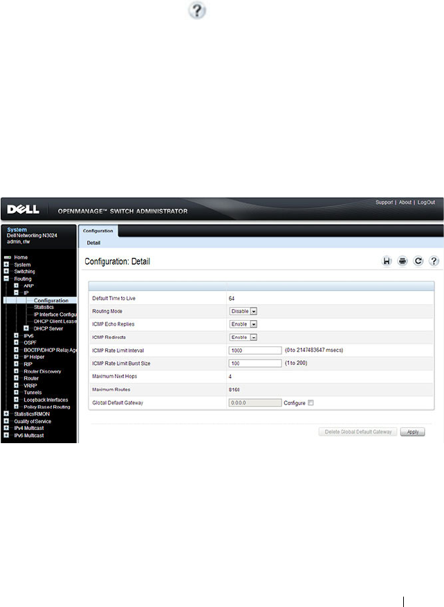
Configuring IP Routing 1067
Configuring IP Routing Features (Web)
This section provides information about the OpenManage Switch
Administrator pages for configuring and monitoring IPv4 routing features on
a Dell Networking N2000, N3000, and N4000 series switches. For details
about the fields on a page, click at the top of the page.
IP Configuration
Use the Configuration
page to configure routing parameters for the switch as
opposed to an interface. The IP configuration settings allow you to enable or
disable the generation of various types of ICMP messages.
To display the page, click Routing
→
IP
→
Configuration in the navigation
panel.
Figure 33-1. IP Configuration

1068 Configuring IP Routing
IP Statistics
The IP statistics reported on the Statistics page are as specified in RFC 1213.
To display the page, click Routing
→
IP
→
Statistics in the navigation panel.
Figure 33-2. IP Statistics
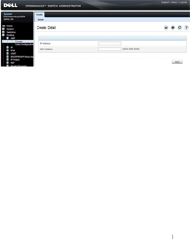
Configuring IP Routing 1069
ARP Create
Use the Create
page to add a static ARP entry to the Address Resolution
Protocol table.
To display the page, click Routing
→
ARP
→
Create in the navigation panel.
Figure 33-3. ARP Create
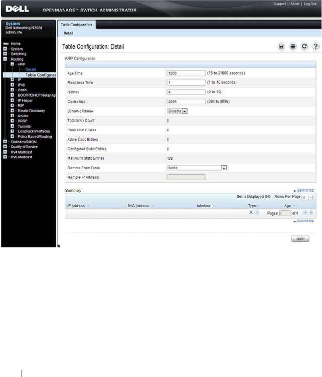
1070 Configuring IP Routing
ARP Table Configuration
Use the Table Configuration page to change the configuration parameters for
the Address Resolution Protocol Table. You can also use this screen to display
the contents of the table.
To display the page, click Routing
→
ARP
→
Table Configuration in the
navigation panel.
Figure 33-4. ARP Table Configuration
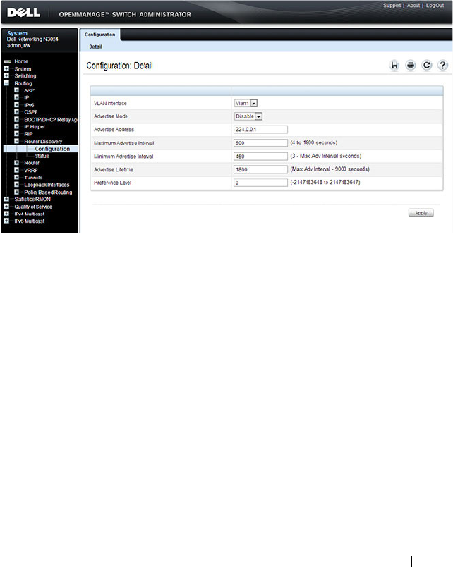
Configuring IP Routing 1071
Router Discovery Configuration
Use the Configuration
page to enter or change router discovery parameters.
To display the page, click Routing
→
Router Discovery
→
Configuration in
the navigation panel.
Figure 33-5. Router Discovery Configuration
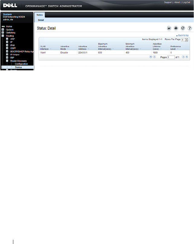
1072 Configuring IP Routing
Router Discovery Status
Use the Status
page to display router discovery data for each interface.
To display the page, click Routing
→
Router Discovery
→
Status in the
navigation panel.
Figure 33-6. Router Discovery Status
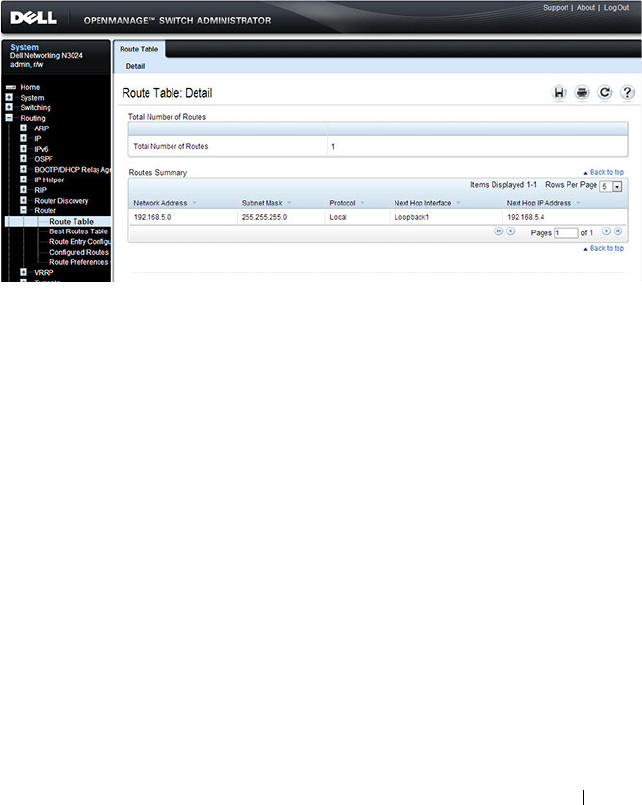
Configuring IP Routing 1073
Route Table
Use the Route Table
page to display the contents of the routing table.
To display the page, click Routing
→
Router
→
Route Table in the navigation
panel.
Figure 33-7. Route Table
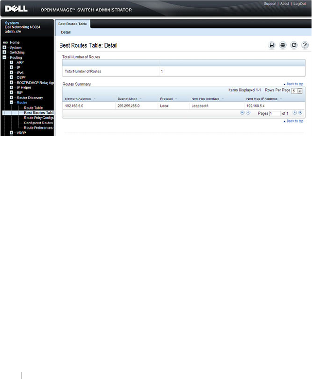
1074 Configuring IP Routing
Best Routes Table
Use the Best Routes Table
page to display the best routes from the routing
table.
To display the page, click Routing
→
Router
→
Best Routes Table in the
navigation panel.
Figure 33-8. Best Routes Table
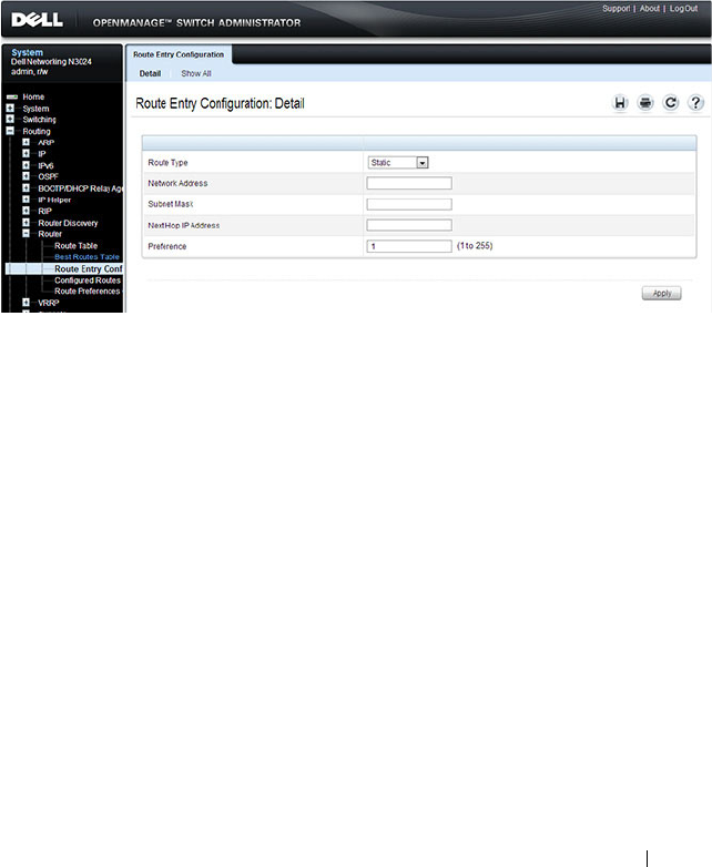
Configuring IP Routing 1075
Route Entry Configuration
Use the Route Entry Configuration
page to add new and configure router
routes.
To display the page, click Routing
→
Router
→
Route Entry Configuration
in the navigation panel.
Figure 33-9. Route Entry Configuration
Adding a Route and Configuring Route Preference
To configure routing table entries:
1
Open the
Route Entry Configuration
page.
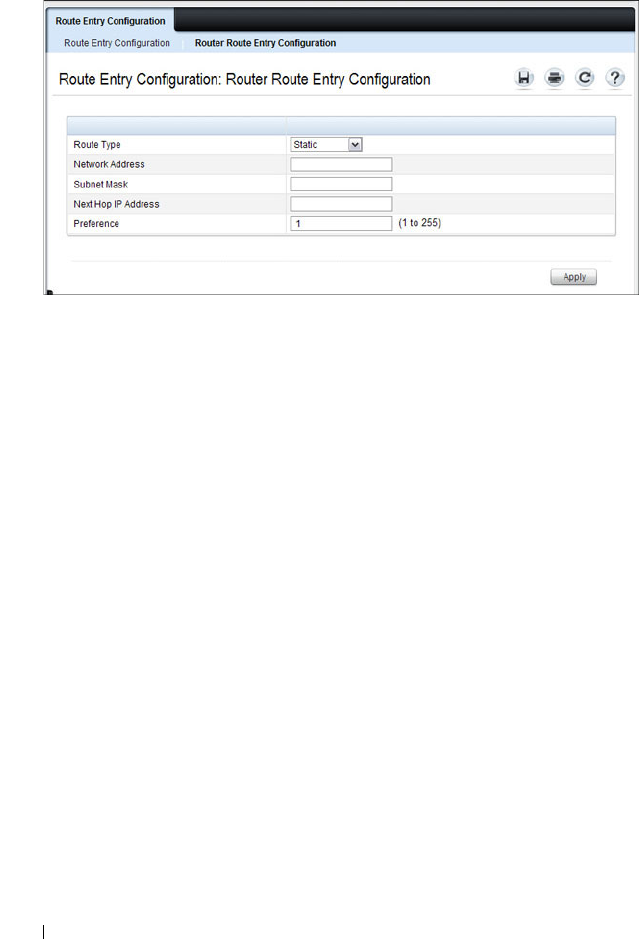
1076 Configuring IP Routing
Figure 33-10. Router Route Entry and Preference Configuration
2
Next to
Route Type,
use the drop-down box to add a
Default, Static, or
Static Reject
route.
The fields to configure are different for each route type.
•
Default
— Enter the default gateway address in the
Next Hop IP
Address
field.
•
Static
— Enter values for
Network Address
,
Subnet Mask
,
Next Hop
IP Address
, and
Preference
.
•
Static Reject
— Enter values for
Network Address
,
Subnet Mask
, and
Preference
.
3
Click
Apply
.
The new route is added to the routing table.
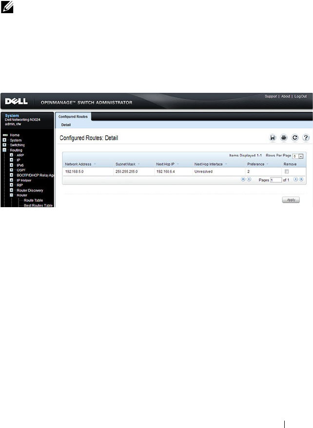
Configuring IP Routing 1077
Configured Routes
Use the Configured Routes
page to display the routes that have been
manually configured.
To display the page, click Routing
→
Router
→
Configured Routes in the
navigation panel.
Figure 33-11. Configured Routes
To remove a configured route, select the check box in the Remove column of
the route to delete, and click Apply.
NOTE: For a static reject route, the next hop interface value is Null0. Packets to
the network address specified in static reject routes are intentionally dropped.
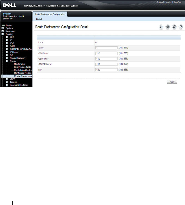
1078 Configuring IP Routing
Route Preferences Configuration
Use the Route Preferences Configuration
page to configure the default
preference for each protocol (for example 60 for static routes). These values
are arbitrary values that range from 1 to 255, and are independent of route
metrics. Most routing protocols use a route metric to determine the shortest
path known to the protocol, independent of any other protocol.
To display the page, click Routing
→
Router
→
Route Preferences
Configuration in the navigation panel.
Figure 33-12. Router Route Preferences Configuration

Configuring IP Routing 1079
Configuring IP Routing Features (CLI)
This section provides information about the commands you use to configure
IPv4 routing on the switch. For more information about the commands, see
the
Dell Networking N2000, N3000, and N4000 Series Switches CLI
Reference Guide
at support.dell.com/manuals.
Configuring Global IP Routing Settings
Beginning in Privileged EXEC mode, use the following commands to
configure various global IP routing settings for the switch.
Command Purpose
configure Enter global configuration mode.
ip routing Globally enable IPv4 routing on the switch.
ip icmp echo-reply Allow the switch to generate ICMP Echo Reply messages.
ip icmp error-interval
burst-interval
[
burst-
size
]
Limit the rate at which IPv4 ICMP error messages are sent.
•
burst-interval
— How often the token bucket is
initialized (Range: 0–2147483647 milliseconds).
•
burst-size
— The maximum number of messages that
can be sent during a burst interval (Range: 1–200).
ip redirects Allow the switch to generate ICMP Redirect messages.
ip default-gateway
ip-
address
Configure the global default gateway for the switch. The
gateway configured here takes precedence over a default
gateway assigned by a network DHCP server.
exit Exit to Privileged EXEC mode.
show ip brief View the global IP settings for the switch.

1080 Configuring IP Routing
Adding Static ARP Entries and Configuring ARP Table Settings
Beginning in Privileged EXEC mode, use the following commands to
configure static ARP entries in the ARP cache and to specify the settings for
the ARP cache.
Command Purpose
configure Enter global configuration mode.
arp
ip-address hardware-
address
Create a static ARP entry in the ARP table.
•
ip-address
— IP address of a device on a subnet attached
to an existing routing interface.
•
hardware
-address
— A unicast MAC address for that
device.
arp timeout
seconds
Configure the ARP entry ageout time.
arp resptime
seconds
Configure the ARP request response timeout.
arp retries
integer
Configure the ARP count of maximum requests for
retries. The range is 1–10.
arp cachesize
integer
Configure the maximum number of entries in the ARP
cache.
arp dynamicrenew Allow the ARP component to automatically renew
dynamic ARP entries when they age out.
exit Exit to Privileged EXEC mode.
show arp [brief] View the user-configured (static) ARP entries. The static
entries display regardless of whether they are reachable
over an interface. Use the brief keyword to view only the
ARP table settings.
clear arp-cache [gateway] Remove all dynamic ARP entries from the ARP cache.
Include the keyword gateway to remove gateway entries as
well.
clear arp-cache
management
Remove all dynamic ARP entries from the ARP cache that
were learned on the management interface.
arp purge
ip-address
Remove the specified IP address from the ARP cache.
This command removes dynamic and gateway ARP entries
only.

Configuring IP Routing 1081
Configuring Router Discovery (IRDP)
Beginning in Privileged EXEC mode, use the following commands to
configure IRDP settings.
Command Purpose
configure Enter global configuration mode.
interface
interface
Enter interface configuration mode for the specified
VLAN routing interface. The
interface
variable includes
the interface type (vlan) and number, for example vlan
100.
ip irdp Enable IRDP on the interface.
ip irdp address
ip-address
Configure the address that the interface uses to send the
router discovery advertisements.
The allowed addresses are 224.0.0.1 (all-hosts IP
multicast address) or 255.255.255.255 (limited broadcast
address)
ip irdp holdtime
seconds
Configure the value of the holdtime field of the router
advertisement sent from this interface.
ip irdp maxadvertinterval
seconds
Configure the maximum time allowed between sending
router advertisements from the interface.
ip irdp minadvertinterval
seconds
Configure the minimum time allowed between sending
router advertisements from the interface.
ip irdp preference
integer
Configure the preference of the address as a default
router address relative to other router addresses on the
same subnet.
exit Exit to Global Config mode.
exit Exit to Privileged EXEC mode.
show ip irdp [vlan
vlan-id
] View the router discovery information for all interfaces,
or for a specified interface.

1082 Configuring IP Routing
Configuring Route Table Entries and Route Preferences
Beginning in Privileged EXEC mode, use the following commands to
configure IRDP settings.
Command Purpose
configure Enter global configuration mode.
ip route default
nextHopRtr
[
preference
]
Configure the default route.
•
nextHopRtr
— IP address of the next hop router.
•
preference
— Specifies the preference value
(administrative distance) of an individual static route.
(Range: 1-255)
ip route
ip-addr
{
subnetmask
|
prefix
length
} {
nextHopRtr |
null
}
[
preference
]
Configure a static route. Use the keyword null instead of
the next hop router IP address to configure a static reject
route.
•
ip-address
— IP address of destination interface.
•
subnet-mask
— Subnet mask of destination interface.
•
prefix-length
— Length of prefix. Must be preceded
with a forward slash (/). (Range: 0-32 bits)
•
nextHopRtr
— IP address of the next hop router.
•
null
— Specifies that the route is a static reject route.
•
preference
— Specifies the preference value
(administrative distance) of an individual static route.
(Range: 1-255)
ip route distance
integer
Set the default distance (preference) for static routes.
Lower route preference values are preferred when
determining the best route.
exit Exit to Privileged EXEC mode.

Configuring IP Routing 1083
show ip route [
ip-address
[
mask
|
prefix-length
]
[longer-prefixes] |
protocol
]
View the routing table.
•
ip-address
— Specifies the network for which the route
is to be displayed and displays the best matching best-
route for the address.
•
mask
— Subnet mask of the IP address.
•
prefix-length
— Length of prefix, in bits. Must be
preceded with a forward slash (‘/’). (Range: 0-32 bits)
•
longer-prefixes
— Indicates that the
ip-address
and
subnet-mask
pair becomes the prefix, and the command
displays the routes to the addresses that match that
prefix.
•
protocol
— Specifies the protocol that installed the
routes. (Range:
connected, ospf, rip, static
)
show ip route configured View the configured routes, whether they are reachable or
not.
show ip route summary View summary information about the routing table.
show ip protocols View the parameters and current state of the active
routing protocols.
show ip route preferences View detailed information about the route preferences.
Command Purpose
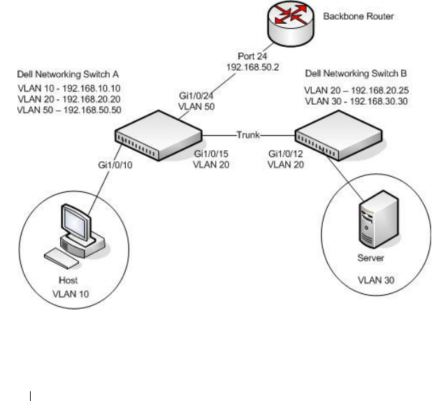
1084 Configuring IP Routing
IP Routing Configuration Example
In this example, the Dell Networking switches are L3 switches with VLAN
routing interfaces. VLAN routing is configured on Dell Networking Switch A
and Dell Networking Switch B. This allows the host in VLAN 10 to
communicate with the server in VLAN 30. A static route to the VLAN 30
subnet is configured on Switch A. Additionally, a default route is configured
on Switch A so that all traffic with an unknown destination is sent to the
backbone router through port 24, which is a member of VLAN 50. A default
route is configured on Dell Networking Switch B to use Switch A as the
default gateway. The hosts use the IP address of the VLAN routing interface
as their default gateway.
This example assumes that all L2 VLAN information, such as VLAN creation
and port membership, has been configured.
Figure 33-13. IP Routing Example Topology

Configuring IP Routing 1085
Configuring Dell Networking Switch A
To configure Switch A.
1
Enable routing on the switch.
console#configure
console(config)#ip routing
2
Assign an IP address to VLAN 10. This command also enables IP routing
on the VLAN.
console(config)#interface vlan 10
console(config-if-vlan10)#ip address 192.168.10.10
255.255.255.0
console(config-if-vlan10)#exit
3
Assign an IP address to VLAN 20.
console#configure
console(config)#interface vlan 20
console(config-if-vlan20)#ip address 192.168.20.20
255.255.255.0
console(config-if-vlan20)#exit
4
Assign an IP address to VLAN 50.
console#configure
console(config)#interface vlan 50
console(config-if-vlan50)#ip address 192.168.50.50
255.255.255.0
console(config-if-vlan50)#exit
5
Configure a static route to the network that VLAN 30 is in, using the IP
address of the VLAN 20 interface on Switch B as the next hop address.
console(config)#ip route 192.168.30.0
255.255.255.0 192.168.20.25
6
Configure the backbone router interface as the default gateway.
console(config)#ip route default 192.168.50.2

1086 Configuring IP Routing
Configuring Dell Networking Switch B
To configure Switch B:
1
Enable routing on the switch.
console#configure
console(config)#ip routing
2
Assign an IP address to VLAN 20. This command also enables IP routing
on the VLAN.
console#configure
console(config)#interface vlan 20
console(config-if-vlan20)#ip address 192.168.20.25
255.255.255.0
console(config-if-vlan20)#exit
3
Assign an IP address to VLAN 30. This command also enables IP routing
on the VLAN.
console#configure
console(config)#interface vlan 30
console(config-if-vlan30)#ip address 192.168.30.30
255.255.255.0
console(config-if-vlan30)#exit
4
Configure the VLAN 20 routing interface on Switch A as the default
gateway so that any traffic with an unknown destination is sent to
Switch A for forwarding.
console(config)#ip route default 192.168.20.20

Configuring L2 and L3 Relay Features 1087
34
Configuring L2 and L3 Relay
Features
This chapter describes how to configure the L2 DHCP Relay, L3 DHCP
Relay, and IP Helper features on Dell Networking series switches.
The topics covered in this chapter include:
• L2 and L3 Relay Overview
• Default L2/L3 Relay Values
• Configuring L2 and L3 Relay Features (Web)
• Configuring L2 and L3 Relay Features (CLI)
• Relay Agent Configuration Example
L2 and L3 Relay Overview
When a DHCP client and server are in the same IP subnet, they can directly
connect to exchange IP address requests and replies. However, buying and
maintaining a DHCP server on each subnet can be expensive and is often
impractical. The relay features on the Dell Networking series switches can
help enable communication between DHCP clients and DHCP servers that
reside in different subnets. Configuring L3 DHCP relay also enables the
bootstrap protocol (BOOTP) relay.
What Is L3 DHCP Relay?
Network infrastructure devices can be used to relay packets between a DHCP
client and server on different subnets. Such a device, an Layer 3 Relay agent,
is often a router or L3 switch. The L3 relay agent must have an IP interface on
the client subnets and, if it does not have an IP interface on the server’s
subnet, it should be able to route traffic toward the server’s subnet.
The Dell Networking DHCP Relay Agent enables DHCP clients and servers
to exchange DHCP messages across different subnets. The relay agent
receives the requests from the clients, and checks the valid hops and
giaddr

1088 Configuring L2 and L3 Relay Features
fields in the DHCP request. If the number of hops is greater than the
configured number, the agent discards the packet. If the
giaddr
field is zero,
the agent must fill in this field with the IP address of the interface on which
the request was received. The agent unicasts the valid packets to all
configured DHCP servers. Each server responds with a unicast BOOTREPLY
addressed to the relay agent closest to the client as indicated by
giaddr
field.
Upon reception of the BOOTREPLY from the server, the agent forwards this
reply as broadcast or unicast on the interface where the BOOTREQUEST
arrived. This interface can be identified by the
giaddr
field or option 82.
The Dell Networking N2000, N3000, and N4000 series switches DHCP
component also supports DHCP relay agent options to identify the client
interface. If configured, the relay agent inserts these options when forwarding
the request to the server and removes them when sending the reply to the
clients.
If an interface has more than one IP address, the relay agent uses the primary
IP address configured as its relay agent IP address.
What Is L2 DHCP Relay?
In Layer 2 switched networks, there may be one or more infrastructure devices
(for example, a switch) between the client and the L3 Relay agent/DHCP
server. In this instance, some of the client device information required by the
L3 Relay agent may not be included in the DHCP packets sent by the DHCP
client. In this case, an L2 Relay agent can be used to add the information that
the L3 Relay Agent and DHCP server need to perform their roles in address
and configuration and assignment.
Before it relays DHCP requests from clients, the switch can add a Circuit ID
and a Remote ID. These IDs provide information about the circuit and port
number connected to the client. This information is added as suboptions in
the DHCP Option 82 packets as defined in sections 3.1 and 3.2 of RFC3046.
The switch removes this option from packets that it relays from L3 Relay
agents/DHCP servers to clients.
These sub-options may be used by the DHCP server to affect how it treats the
client and also may be used by the relay agent to limit broadcast replies to the
specific circuit or attachment point of the client.

Configuring L2 and L3 Relay Features 1089
Enabling L2 Relay on VLANs
You can enable L2 DHCP relay on a particular VLAN. The VLAN is identified
by a service VLAN ID (S-VID), which a service provider uses to identify a
customer’s traffic while traversing the provider network to multiple remote
sites. The switch uses the VLAN membership of the switch port client (the
customer VLAN ID, or C-VID) to perform a lookup a corresponding S-VID.
If the S-VID is enabled for DHCP Relay, then the packet can be forwarded. If
the C-VID does not correspond to an S-VID that is enabled for DHCP Relay,
then the switch will not relay the DHCP request packet.
What Is the IP Helper Feature?
The IP Helper feature provides the ability for a router to forward configured
UDP broadcast packets to a particular IP address. This allows applications to
reach servers on non-local subnets. This is possible even when the application
is designed to assume a server is always on a local subnet or when the
application uses broadcast packets to reach the server (with the limited
broadcast address 255.255.255.255, or a network directed broadcast address).
You can configure relay entries globally and on routing interfaces. Each relay
entry maps an ingress interface and destination UDP port number to a single
IPv4 address (the helper address). Multiple relay entries may be configured
for the same interface and UDP port, in which case the relay agent relays
matching packets to each server address. Interface configuration takes priority
over global configuration. If the destination UDP port for a packet matches
any entry on the ingress interface, the packet is handled according to the
interface configuration. If the packet does not match any entry on the ingress
interface, the packet is handled according to the global IP helper
configuration.
You can configure discard relay entries. Discard entries are used to discard
packets received on a specific interface when those packets would otherwise
be relayed according to a global relay entry. Discard relay entries may be
configured on interfaces, but are not configured globally.
Additionally, you can configure which UDP ports are forwarded. Certain UDP
port numbers can be selected from the web interface or specified by name in
the CLI, but you can also configure a relay entry with any UDP port number.
You may configure relay entries that do not specify a destination UDP port.
The relay agent assumes that these entries match packets with the UDP
destination ports listed in Table 34-1 (the list of default ports).

1090 Configuring L2 and L3 Relay Features
Table 34-1. Default Ports - UDP Port Numbers Implied By Wildcard
The system limits the total number of relay entries to four times the
maximum number of routing interfaces (512 relay entries). There is no
individual limit to the number of relay entries on an individual interface, and
no individual limit to the number of servers for a given {interface, UDP port}
pair. The system limit applies in these cases.
Certain configurable DHCP relay options do not apply to relay of other
protocols. You may optionally set a maximum hop count or minimum wait
time using the bootpdhcprelay maxhopcount and bootpdhcprelay
minwaittime commands.
The relay agent relays DHCP packets in both directions. It relays broadcast
packets from the client to one or more DHCP servers, and relays packets to
the client that the DHCP server unicasts back to the relay agent. For other
protocols, the relay agent only relays broadcast packets from the client to the
server. Packets from the server back to the client are assumed to be unicast
directly to the client. Because there is no relay in the return direction for
protocols other than DHCP, the relay agent retains the source IP address from
the original client packet. The relay agent uses a local IP address as the source
IP address of relayed DHCP client packets.
When a switch receives a broadcast UDP packet on a routing interface, the
relay agent verifies that the interface is configured to relay to the destination
UDP port. If so, the relay agent unicasts the packet to the configured server IP
addresses. Otherwise, the relay agent verifies that there is a global
Protocol UDP Port Number
IEN-116 Name Service 42
DNS 53
NetBIOS Name Server 137
NetBIOS Datagram Server 138
TACACS Server 49
Time Service 37
DHCP 67
Trivial File Transfer Protocol 69

Configuring L2 and L3 Relay Features 1091
configuration for the destination UDP port. If so, the relay agent unicasts the
packet to the configured server IP addresses. Otherwise the packet is not
relayed.
The relay agent relays packets that meet only the following conditions:
• The destination MAC address must be the all-ones broadcast address
(FF:FF:FF:FF:FF:FF).
• The destination IP address must be the limited broadcast address
(255.255.255.255) or a directed broadcast address for the receive interface.
• The IP time-to-live (TTL) must be greater than 1.
• The protocol field in the IP header must be UDP (17).
• The destination UDP port must match a configured relay entry.
NOTE: If the packet matches a discard relay entry on the ingress interface, the
packet is not forwarded, regardless of the global configuration.

1092 Configuring L2 and L3 Relay Features
Table 34-2 shows the most common protocols and their UDP port numbers
and names that are relayed.
Table 34-2. UDP Port Allocations
UDP Port Number Acronym Application
7 Echo Echo
11 SysStat Active User
15 NetStat NetStat
17 Quote Quote of the day
19 CHARGEN Character Generator
20 FTP-data FTP Data
21 FTP FTP
37 Time Time
42 NAMESERVER Host Name Server
43 NICNAME Who is
53 DOMAIN Domain Name Server
69 TFTP Trivial File Transfer
111 SUNRPC Sun Microsystems Rpc
123 NTP Network Time
137 NetBiosNameService NT Server to Station Connections
138 NetBiosDatagramService NT Server to Station Connections
139 NetBios SessionServiceNT Server to Station
Connections
161 SNMP Simple Network Management
162 SNMP-trap Simple Network Management Traps
513 who Unix Rwho Daemon
514 syslog System Log
525 timed Time Daemon

Configuring L2 and L3 Relay Features 1093
Default L2/L3 Relay Values
By default L2 DHCP relay is disabled. L3 relay (UDP) is enabled, but no UDP
destination ports or server addresses are defined on the switch or on any
interfaces.
Table 34-3. L2/L3 Relay Defaults
Parameter Default Value
L2 DHCP Relay
Admin Mode Disabled globally and on all interfaces and
VLANs
Trust Mode Disabled on all interfaces
Circuit ID Disabled on all VLANs
Remote ID None configured
L3 DHCP Relay
UDP Relay Mode (IP Helper) Enabled
Hop Count 4
Minimum Wait Time 0 seconds
Circuit ID Option Mode Disabled
Circuit ID Check Mode Enabled
Information Option-Insert Disabled on all VLAN interfaces
Information Check-Reply Enabled on all VLAN interfaces
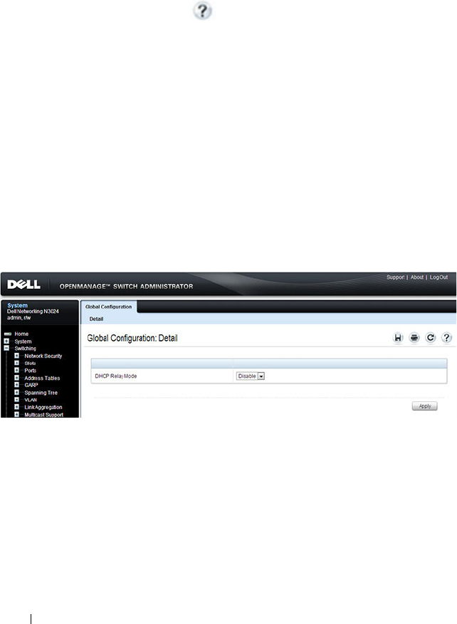
1094 Configuring L2 and L3 Relay Features
Configuring L2 and L3 Relay Features (Web)
This section provides information about the OpenManage Switch
Administrator pages for configuring and monitoring L2 and L3 relay features
on a Dell Networking N2000, N3000, and N4000 series switches. For details
about the fields on a page, click at the top of the page.
DHCP Relay Global Configuration
Use this page to enable or disable the switch to act as a DHCP Relay agent.
This functionality must also be enabled on each port you want this service to
operate on (see "DHCP Relay Interface Configuration" on page 1095). The
switch can also be configured to relay requests only when the VLAN of the
requesting client corresponds to a service provider’s VLAN ID that has been
enabled with the L2 DHCP relay functionality (see "DHCP Relay VLAN
Configuration" on page 1098).
To access this page, click Switching
→
DHCP Relay
→
Global
Configuration in the navigation panel.
Figure 34-1. DHCP Relay Global Configuration

Configuring L2 and L3 Relay Features 1095
DHCP Relay Interface Configuration
Use this page to enable L2 DHCP relay on individual ports.
To access this page, click Switching
→
DHCP Relay
→
Interface
Configuration in the navigation panel.
Figure 34-2. DHCP Relay Interface Configuration
To view a summary of the L2 DHCP relay configuration on all ports and
LAGS, click Show All.
NOTE: L2 DHCP relay must also be enabled globally on the switch.

1096 Configuring L2 and L3 Relay Features
Figure 34-3. DHCP Relay Interface Summary
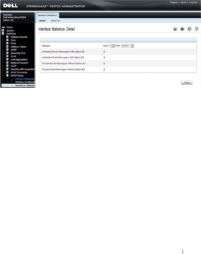
Configuring L2 and L3 Relay Features 1097
DHCP Relay Interface Statistics
Use this page to display statistics on DHCP Relay requests received on a
selected port. To access this page, click Switching
→
DHCP Relay
→
Interface Statistics in the navigation panel.
Figure 34-4. DHCP Relay Interface Statistics
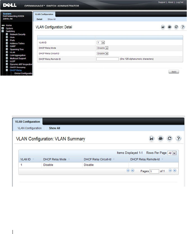
1098 Configuring L2 and L3 Relay Features
DHCP Relay VLAN Configuration
Use this page to enable and configure DHCP Relay on specific VLANs.
To access this page, click Switching
→
DHCP Relay
→
VLAN
Configuration in the navigation panel.
Figure 34-5. DHCP Relay VLAN Configuration
To view a summary of the L2 DHCP relay configuration on all VLANs, click
Show All.
Figure 34-6. DHCP Relay VLAN Summary
DHCP Relay Agent Configuration
Use the Configuration
page to configure and display a DHCP relay agent.
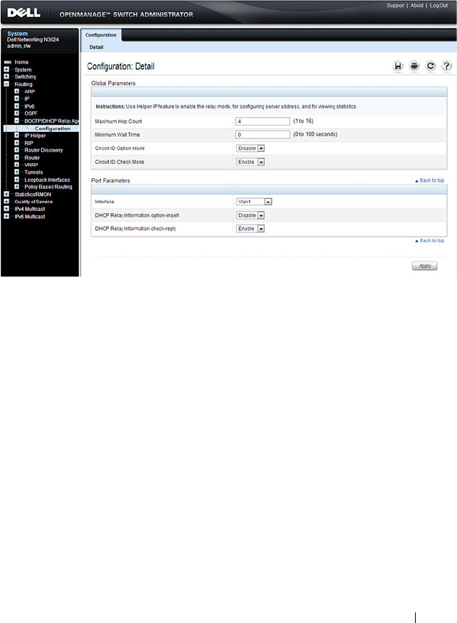
Configuring L2 and L3 Relay Features 1099
To display the page, click Routing
→
BOOTP/DHCP Relay Agent
→
Configuration in the navigation panel.
Figure 34-7. DHCP Relay Agent Configuration
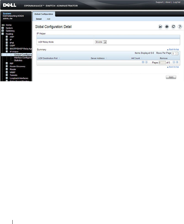
1100 Configuring L2 and L3 Relay Features
IP Helper Global Configuration
Use the Global Configuration page to add, show, or delete UDP Relay and
Helper IP configuration
To display the page, click Routing
→
IP Helper
→
Global Configuration in
the navigation panel.
Figure 34-8. IP Helper Global Configuration
Adding an IP Helper Entry
To configure an IP helper entry:
1.
Open the IP Helper
Global Configuration
page
.
2.
Click
Add
to display the
Add Helper IP Address page
:

Configuring L2 and L3 Relay Features 1101
Figure 34-9. Add Helper IP Address
3.
Select a UDP Destination port name from the menu or enter the UDP
Destination Port ID. Select the Default Set to configure for the relay entry
for the default set of protocols.
4.
Enter the IP address of the server to which the packets with the given UDP
Destination Port will be relayed.
5.
Click
Apply
.
The UDP/Helper Relay is added and the device is updated.
NOTE: If the DefaultSet option is specified, the device by default forwards
UDP Broadcast packets for the following services: IEN-116 Name Service
(port 42), DNS (port 53), NetBIOS Name Server (port 137), NetBIOS Datagram
Server (port 138), TACACS Server (Port 49), and Time Service (port 37).
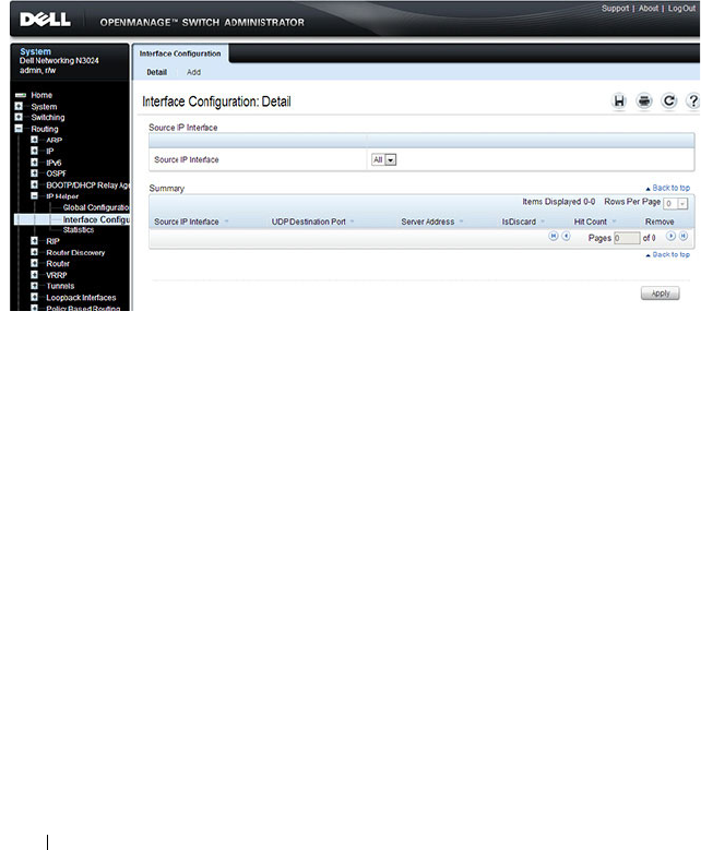
1102 Configuring L2 and L3 Relay Features
IP Helper Interface Configuration
Use the Interface Configuration page to add, show, or delete UDP Relay and
Helper IP configuration for a specific interface.
To display the page, click Routing
→
IP Helper
→
Interface Configuration
in the navigation panel.
Figure 34-10. IP Helper Interface Configuration
Adding an IP Helper Entry to an Interface
To add an IP helper entry to an interface:
1.
Open the IP Helper
Interface Configuration
page.
2.
Click
Add
to display the
Add IP Helper Address
page
:
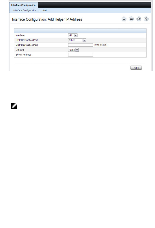
Configuring L2 and L3 Relay Features 1103
Figure 34-11. Add Helper IP Address
3.
Select the interface to use for the relay.
4.
Select a UDP Destination port name from the menu or enter the UDP
Destination Port ID. Select the Default Set to configure for the relay entry
for the default set of protocols.
5.
Choose whether to discard (True) or keep (False)
packets arriving on the
given interface with the given destination UDP port.
6.
Enter the IP address of the server to which the packets with the given UDP
Destination Port will be relayed.
7.
Click
Apply
.
The UDP/Helper Relay is added to the interface and the device is updated.
NOTE: If the DefaultSet option is specified, the device by default forwards
UDP Broadcast packets for the following services: IEN-116 Name Service
(port 42), DNS (port 53), NetBIOS Name Server (port 137), NetBIOS Datagram
Server (port 138), TACACS Server (Port 49), and Time Service (port 37).
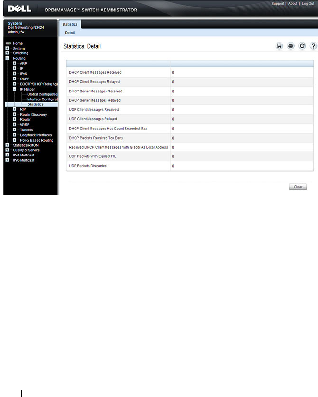
1104 Configuring L2 and L3 Relay Features
IP Helper Statistics
Use the Statistics page to view UDP Relay Statistics for the switch.
To display the page, click Routing
→
IP Helper
→
Statistics in the navigation
panel.
Figure 34-12. IP Helper Statistics

Configuring L2 and L3 Relay Features 1105
Configuring L2 and L3 Relay Features (CLI)
This section provides information about the commands you use to configure
L2 and L3 relay features on the switch. For more information about the
commands, see the
Dell Networking N2000, N3000, and N4000 Series
Switches CLI Reference Guide
at support.dell.com/manuals.
Configuring L2 DHCP Relay
Beginning in Privileged EXEC mode, use the following commands to
configure switch and interface L2 DHCP relay settings.
Command Purpose
configure Enter global configuration mode.
dhcp l2relay Globally enable L2 DHCP relay on the switch
interface
interface
Enter interface configuration mode for the specified port
or LAG. The
interface
variable includes the interface type
and number, for example tengigabitethernet 1/0/3. For a
LAG, the interface type is port-channel.
You can also specify a range of ports with the interface
range command, for example, interface range
tengigabitethernet 1/0/8-12 configures interfaces 8, 9, 10,
11, and 12.
dhcp l2relay Enable L2 DHCP relay on the port(s) or LAG(s).
dhcp l2relay trust Configure the interface(s) to mandate Option-82 on
receiving DHCP packets.
exit Exit to Global Configuration mode.
dhcp l2relay vlan
vlan-
range
Enable the L2 DHCP Relay agent for a set of VLANs. All
DHCP packets which arrive on interfaces in the configured
VLAN are subject to L2 Relay processing.
dhcp l2relay circuit-id
vlan
vlan-range
Enable setting the DHCP Option 82 Circuit ID for a
VLAN. When enabled, the interface number is added as
the Circuit ID in DHCP option 82.

1106 Configuring L2 and L3 Relay Features
dhcp l2relay remote-id
remoteId
vlan
vlan-range
Enable setting the DHCP Option 82 Remote ID for a
VLAN. When enabled, the supplied string is used for the
Remote ID in DHCP Option 82.
The
remoteId
variable is a string to be used as the remote
ID in the Option 82 (Range: 1 - 128 characters).
exit Exit to Privileged EXEC mode.
show dhcp l2relay all View L2 DHCP relay settings on the switch.
show dhcp l2relay
interface [all |
interface
]
View L2 DHCP relay settings for all interfaces or for the
specified interface.
show dhcp l2relay vlan
vlan-range
View L2 DHCP relay settings for the specified VLAN
show dhcp l2relay stats
interface [all |
interface
]
View the number of DHCP packets processed and relayed
by the L2 relay agent. To reset the statistics to 0, use the
clear dhcp l2relay statistics interface [all |
interface
]
command.
show dhcp l2relay agent-
option vlan
vlan-id
View the DHCP L2 Relay Option-82 configuration for the
specified VLAN.
show dhcp l2relay
circuit-id vlan
vlan-id
View the DHCP L2 Relay circuit ID configuration for the
specified VLAN.
show dhcp l2relay
remote-id vlan
vlan-id
View the DHCP L2 Relay remote ID configuration for the
specified VLAN.
Command Purpose

Configuring L2 and L3 Relay Features 1107
Configuring L3 Relay (IP Helper) Settings
Beginning in Privileged EXEC mode, use the following commands to
configure switch and interface L3 DHCP relay and IP helper settings.
Command Purpose
configure Enter global configuration mode.
ip helper enable Use this command to enable the IP helper feature. It is
enabled by default.
ip helper-address
server-
address
[
dest-udp-port
|
dhcp | domain | isakmp
| mobile-ip |
nameserver | netbios-
dgm | netbios-ns | ntp |
pim-auto-rp | rip |
tacacs | tftp | time]
Configure the relay of certain UDP broadcast packets
received on any interface. Specify the one of the protocols
defined in the command or the UDP port number.
•
server-address
— The IPv4 unicast or directed broadcast
address to which relayed UDP broadcast packets are sent.
The server address cannot be an IP address configured on
any interface of the local router.
•
dest-udp-port
— A destination UDP port number from 0
to 65535.
interface vlan
vlan-id
Enter interface configuration mode for the specified
VLAN routing interface.
You can also specify a range of VLAN routing interfaces
with the interface range vlan command, for example,
interface range vlan 10,20,30 configures VLAN interfaces
10, 20, and 30.
NOTE: All VLANs must be configured as VLAN routing
interfaces.

1108 Configuring L2 and L3 Relay Features
ip helper-address
{
server-address
|
discard} [
dest-udp-port
| dhcp | domain |
isakmp | mobile-ip |
nameserver | netbios-
dgm | netbios-ns | ntp |
pim-auto-rp | rip |
tacacs | tftp | time]
Configure the relay of certain UDP broadcast packets
received on the VLAN routing interface(s). This command
takes precedence over an ip helper-address command given
in global configuration mode.
Specify the one of the protocols defined in the command
or the UDP port number.
•
server-address
— The IPv4 unicast or directed broadcast
address to which relayed UDP broadcast packets are sent.
The server address cannot be an IP address configured on
any interface of the local router.
•
dest-udp-port
— A destination UDP port number from 0
to 65535.
exit Exit to Global Config mode.
exit Exit to Privileged EXEC mode.
show ip helper-address
[vlan
vlan-id
]
View IP helper (L3 relay) settings for all interfaces or for
the specified VLAN routing interface.
show ip helper statistics View the number of DHCP and other UDP packets
processed and relayed by the UDP relay agent. To reset the
statistics to 0, use the clear ip helper statistics command.
Command Purpose
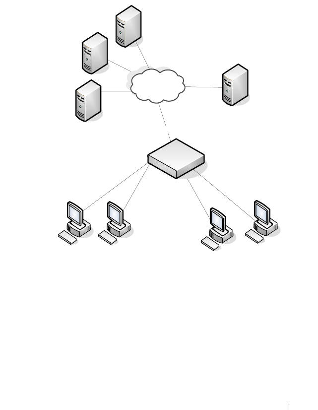
Configuring L2 and L3 Relay Features 1109
Relay Agent Configuration Example
The example in this section shows how to configure the L3 relay agent (IP
helper) to relay and discard various protocols.
Figure 34-13. L3 Relay Network Diagram
This example assumes that multiple VLAN routing interfaces have been
created, and configured with IP addresses.
To configure the switch:
1
Relay DHCP packets received on VLAN 10 to 192.168.40.35
console#config
console(config)#interface vlan 10
console(config-if-vlan10)#ip helper-address
192.168.40.35 dhcp
VLAN 30
` ` ``
DHCP Server
192.168.40.35
DHCP Clients
VLAN 10
L3 Switch
VLAN 20 (No DHCP)
DHCP Server
192.168.40.22
SNMP Server
192.168.23.1
DNS Server
192.168.40.43

1110 Configuring L2 and L3 Relay Features
2
Relay DNS packets received on VLAN 10 to 192.168.40.43
console(config-if-vlan10)#ip helper-address
192.168.40.35 domain
console(config-if-vlan10)#exit
3
Relay SNMP traps (port 162) received on VLAN 20 to 192.168.23.1
console(config)#interface vlan 20
console(config-if-vlan20)#ip helper-address
192.168.23.1 162
4
The clients on VLAN 20 have statically-configured network information,
so the switch is configured to drop DHCP packets received on VLAN 20
console(config-if-vlan20)#ip helper-address
discard dhcp
console(config-if-vlan20)#exit
5
DHCP packets received from clients in any VLAN other than VLAN 10
and VLAN 20 are relayed to 192.168.40.22.
console(config)#ip helper-address 192.168.40.22
dhcp
6
Verify the configuration.
console#show ip helper-address
IP helper is enabled
NOTE: The following command is issued in Global Configuration mode, so it
applies to all interfaces except VLAN 10 and VLAN 20. IP helper commands
issued in Interface Configuration mode override the commands issued in
Global Configuration Mode.
I/F UDP Port Discard Hit Count Server Address
---- -------- ----- --------- ---------------
Vl10 domain No 0 192.168.40.43
Vl10 dhcp No 0 192.168.40.35
Vl20 dhcp Yes 0
Vl20 162 No 0 192.168.23.1
Any dhcp No 0 192.168.40.22

Configuring OSPF and OSPFv3 1111
35
Configuring OSPF and OSPFv3
This chapter describes how to configure Open Shortest Path First (OSPF)
and OSPFv3. OSPF is a dynamic routing protocol for IPv4 networks, and
OSPFv3 is used to route traffic in IPv6 networks. The protocols are
configured separately within the software, but their functionality is largely
similar for IPv4 and IPv6 networks.
The topics covered in this chapter include:
• OSPF Overview
•OSPF Feature Details
• Default OSPF Values
• Configuring OSPF Features (Web)
• Configuring OSPFv3 Features (Web)
• Configuring OSPF Features (CLI)
• Configuring OSPFv3 Features (CLI)
• OSPF Configuration Examples
NOTE: In this chapter references to OSPF apply to OSPFv2 and OSPFv3 unless
otherwise noted.
NOTE: N2000 switches do not support OSPF.

1112 Configuring OSPF and OSPFv3
OSPF Overview
OSPF is an Interior Gateway Protocol (IGP) that performs dynamic routing
within a network. Dell Networking series switches support two dynamic
routing protocols: OSPF and Routing Information Protocol (RIP).
Unlike RIP, OSPF is a link-state protocol. Larger networks typically use the
OSPF protocol instead of RIP.
What Are OSPF Areas and Other OSPF Topology Features?
The top level of the hierarchy of an OSPF network is known as an OSPF
domain. The domain can be divided into areas. Routers within an area must
share detailed information on the topology of their area, but require less
detailed information about the topology of other areas. Segregating a network
into areas enables limiting the amount of route information communicated
throughout the network.
Areas are identified by a numeric ID in IP address format n.n.n.n (note,
however, that these are not used as actual IP addresses). For simplicity, the
area can be configured and referred to in normal integer notation. For
example, Area 20 is identified as 0.0.0.20 and Area 256 as 0.0.1.0. The area
identified as 0.0.0.0 is referred to as Area 0 and is considered the OSPF
backbone. All other OSPF areas in the network must connect to Area 0
directly or through a virtual link. The backbone area is responsible for
distributing routing information between non-backbone areas.
A virtual link can be used to connect an area to Area 0 when a direct link is
not possible. A virtual link traverses an area between the remote area and Area
0.
A stub area is an area that does not accept external LSAs (LSAs generated by
redistributing routes) that were learned from a protocol other than OSPF or
were statically configured. These routes typically send traffic outside the AS.
Therefore, routes from a stub area to locations outside the AS use the default
gateway. A virtual link cannot be configured across a stub area. A Not So
Stubby Area can import limited external routes only from a connected ASBR.

Configuring OSPF and OSPFv3 1113
What Are OSPF Routers and LSAs?
When a Dell Networking switch is configured to use OSPF for dynamic
routing, it is considered to be an OSPF router. OSPF routers keep track of the
state of the various links they send data to. Routers exchange OSPF link state
advertisements (LSAs) with other routers. External LSAs provide information
on static routes or routes learned from other routing protocols.
OSPF defines various router types:
• Backbone routers have an interface in Area 0.
• Area border routers (ABRs) have interfaces in multiple areas.
• Internal routers have all their interfaces in a single OSPF area.
• Autonomous system boundary routers (ASBRs) redistribute routes from
other protocols and originate external LSAs.
How Are Routes Selected?
OSPF determines the best route using the route metric and the type of the
OSPF route. The following order is used for choosing a route if more than one
type of route exists:
1
Intra-area (the destination prefix is in the same area as the router
computing the route)
2
Inter-area (the destination is not in the same area as the router computing
the route
3
External Type 1
4
External Type 2
How Are OSPF and OSPFv3 Different?
OSPFv3 is the Open Shortest Path First routing protocol for IPv6. It is similar
to OSPFv2 in its concept of a link state database, intra/inter area, and AS
external routes and virtual links. It differs from its IPv4 counterpart in a
number of respects. Peering is done through link-local addresses, and the
protocol is link rather than network centric; and addressing semantics have
been moved to leaf LSAs.

1114 Configuring OSPF and OSPFv3
OSPF Feature Details
This section provides details on the following OSPF features:
•Max Metric
• Static Area Range Cost
•LSA Pacing
•LSA Pacing
Max Metric
RFC 3137 introduced stub router behavior to OSPFv2. As a stub, a router can
inform other routers that it is not available to forward data packets. This can
be useful if OSPF has run out of resources (for example, memory) to compute
a complete routing table, or to avoid routing transients as OSPF learns its
neighbors and a complete set of routes at startup. Thus, OSPF can enter stub
router mode either automatically (as a result of a resource condition) or by
configuration.
When OSPF enters stub router mode, it re-originates its router LSAs and sets
the metric on each of its non-stub links to the maximum value, 0xFFFF.
Whenever OSPF originates a router LSA while in stub router mode, it sets
the metrics in this way. Stub router mode is global and applies to router LSAs
for all areas. Other routers prefer alternate paths that avoid the stub router;
however, if no alternate path is available, another router may compute a
transit route through a stub router. Because the stub router does not adjust
the metric for stub links in its router LSA, routes to destinations on these
networks are unaffected. Thus, stub router mode does not affect
management connections to the router, even if the router and management
station depend on OSPF routes to communicate with each other.
The feature supports two modes of operation. The network administrator can
put OSPF in stub router mode. OSPF remains in stub router mode until the
network administrator takes OSPF out of stub router mode. Alternatively, the
network administrator can configure OSPF to start in stub router mode for a
configurable period of time after the router boots up. On a stack, the startup
period also applies when a unit takes over as the management unit. The
clear configuration command also restarts OSPF in stub router

Configuring OSPF and OSPFv3 1115
mode. OSPF does not begin in stub router mode when OSPF is globally
enabled. If the operator wants to avoid routing transients when he enables or
configures OSPF, he can manually set OSPF in stub router mode.
If OSPF is in startup stub router mode and encounters a resource limitation
that would normally cause OSPF to become a stub router, OSPF cancels the
timer to exit startup stub router and remains in stub router mode until the
network administrator takes action.
The network administrator can optionally configure OSPF to override the
metric in summary LSAs while in stub router mode. The option applies to
both type 3 and type 4 summary LSAs.
When a router is in stub router mode, all its virtual links are down. This is
because the cost to the virtual neighbor is guaranteed to be greater than or
equal to 0xFFFF. RFC 2328 section 15 states that:
“...a virtual link whose underlying path has cost greater than hexadecimal
0xffff (the maximum size of an interface cost in a router-LSA) should be
considered non-operational.”
To configure a router for stub router mode, use the max-metric router-
lsa command in Global Router Configuration mode. The following example
sets the router to start in stub router mode on a restart and remain in stub
router mode for 5 minutes:
ABR-R0(config)#router ospf
ABR-R0(config-router)#max-metric router-lsa on-startup 300
The following example sets the router to advertise the metric in type 3 and
type 4 summary LSAs as 32768 for 5 minutes after a restart, after which time
the router will exit stub router mode and advertise the full set of LSAs:
ABR-R0(config)#router ospf
ABR-R0(config-router)#max-metric router-lsa on-startup 300 summary-
lsa 32768
The following example causes the router to exit stub router mode, whether
entered automatically due to resource constraints or due to configuration by
the operator. Virtual links are enabled when the router exits stub router mode.
ABR-R0(config)#router ospf
ABR-R0(config-router)#no max-metric router-lsa

1116 Configuring OSPF and OSPFv3
Static Area Range Cost
This feature allows a network operator to configure a fixed OSPF cost that is
always advertised when an area range is active. This feature applies to both
OSPFv2 and OSPFv3.
An OSPF domain can be divided into areas to limit the processing required
on each router. Area Border Routers (ABRs) advertise reachability across area
boundaries. It is common to summarize the set of prefixes that an ABR
advertises across an area boundary. RFC 2328 specifies that when an ABR
originates a type 3 LSA for an active area range, the cost in the LSA is set to
“the largest cost of any of the component networks.” Thus, when an area's
topology changes in a way that increases the largest cost, the type 3 LSA must
be re-originated. In some cases, advertising the change in cost may be less
important than preventing the topology change from propagating outside the
area (thus causing routers in other areas to process and flood a changed LSA
and rerun their routing table calculations). For this reason, it is common to
give the network administrator the option of configuring the cost for an area
range. When a static cost is configured, the cost advertised in the type 3 LSA
does not depend on the cost of the component networks. Thus, topology
changes within an area do not propagate outside the area, resulting in greater
stability within the OSPF domain.
Dell Networking switches also use area ranges to summarize type 7 LSAs
when they are translated to type 5 LSAs. The cost option may be configured
on area ranges used for type 7 to type 5 translation.
If an area range is configured for type 3 summarization and the static cost is
set to the maximum value, 16,777,215, the range is not advertised. Setting
this static cost is equivalent to configuring a range with the not-advertise
option. A summary LSA with this metric (LSInfinity) cannot be advertised,
according to RFC 2328 section 12.4.3. This behavior is consistent with the
industry standard.
If an area range is configured for type 7 to type 5 translation, a type 5 LSA is
sent if the metric is set to 16,777,215; however, other routers will not compute
a route from a type 5 LSA with this metric.
See "Configuring the Static Area Range Cost" on page 1190 for a
configuration example.

Configuring OSPF and OSPFv3 1117
LSA Pacing
OSPF refreshes each self-originated LSA every 30 minutes. Because a router
tends to originate many LSAs at the same time, either at startup or when
adjacencies are formed or when routes are first learned, LSA refreshes tend to
be grouped. Further, Area Border Routers (ABRs) attached to the same area
tend to originate summary LSAs into the area at the same time. This behavior
leads to periodic bursts of LS Update packets. Update bursts can lead to high
CPU utilization, packet loss, and retransmission, if a receiver cannot absorb
all packets in a burst. These losses occur primarily in two places: 1) at the
Class of Service (CoS) queue where the hardware queues packets to the CPU,
and 2) when a message buffer is allocated for an incoming packet.
This feature makes changes to OSPFv2 to improve the efficiency of LSA
flooding, with the expectation that the improvements will greatly reduce or
eliminate the packet drops caused by bursts in OSPF control packets. The
changes are as follows:
• Introduce LSA transmit pacing, limiting the rate of LS Update packets
that OSPF can send
• Introduce LSA refresh groups, so that OSPF efficiently bundles LSAs into
LS Update packets when periodically refreshing self-originated LSAs
To configure LSA transmit pacing, use the timers pacing flood command in
router config mode:
ABR-R0(config)#router ospf
ABR-R0(config-router)#timers pacing flood 50
This will cause LSA Update packets to be sent at no less than a 50 millisecond
interval.
When OSPF refreshes LSAs, it considers all self-originated LSAs whose age is
from 1800 to 1800 plus the pacing group size. Grouping LSAs for refresh
allows OSPF to combine refreshed LSAs into a minimal number of LS
Update packets. Minimizing the number of Update packets makes LSA
distribution more efficient. To configure an LSA Refresh window, use the
timers pacing lsa-group command in router-config mode:
ABR-R0(config)#router ospf
ABR-R0(config-router)#timers pacing lsa-group 300
This sets the LSA Refresh window to 2100 seconds or about 35 minutes.

1118 Configuring OSPF and OSPFv3
Flood Blocking
OSPF is a link state routing protocol. Routers describe their local
environment in Link State Advertisements (LSAs), which are distributed
throughout an area or OSPF domain. Through this process, each router learns
enough information to compute a set of routes consistent with the routes
computed by all other routers.
Normally, OSPF floods an LSA on all interfaces within the LSA's flooding
scope. Flooding ensures that all routers receive all LSAs. A router normally
receives a duplicate copy of each LSA once on each interface in the LSA's
flooding scope. The duplicate deliveries make OSPF LSA distribution robust,
but in highly interconnected networks, can cause a lot of buffer and CPU
usage. Buffer and CPU use can be reduced by selectively blocking LSA
flooding on some interfaces, while ensuring that LSAs are flooded on enough
interfaces to guarantee delivery of all LSAs to all routers. When enabling
flood blocking, the network administrator must ensure there is sufficient LSA
flooding even when there are router and link failures.
This feature enables a network administrator to disable LSA flooding on an
interface. Flood blocking only affects flooding of LSAs with area or AS (i.e.,
domain-wide) scope. Such LSAs are expected to be flooded to neighbors on
other, unblocked interfaces, and eventually reach neighbors on blocked
interfaces. An LSA with interface flooding scope cannot be blocked; there is
no other way for interface-scope LSAs to reach neighbors on the blocked
interface. Allowing interface-scope LSAs on blocked interfaces allows graceful
restart to work, even if the restarting router has neighbors on flood blocked
interfaces.
When an interface is blocked, LSAs with area or AS scope are not sent to any
neighbor on that interface. When flood blocking is enabled, OSPF does not
advertise any LSAs with area or AS scope in its database description packets
sent to neighbors on a blocked interface. When OSPF receives an LSA from a
neighbor and the local database copy is newer than the received LSA, OSPF
normally sends the newer LSA directly to the neighbor. If the neighbor is on a
blocked interface, OSPF neither acknowledges the LSA nor sends the newer
LSA. Instead, OSPF expects that the neighbor will receive the newer LSA
indirectly.
Flooding is enabled by default.

Configuring OSPF and OSPFv3 1119
Flood blocking cannot be enabled on virtual interfaces. While the feature
could be allowed on virtual interfaces, it is less likely to be used on a virtual
interface, since virtual interfaces are created specifically to allow flooding
between two backbone routers. So the option of flood blocking on virtual
interfaces is not supported.
See "Configuring Flood Blocking" on page 1195 for a configuration example.

1120 Configuring OSPF and OSPFv3
Default OSPF Values
OSPF is globally enabled by default. To make it operational on the router, you
must configure a router ID and enable OSPF on at least one interface.
Table 35-1 shows the global default values for OSPF and OSPFv3.
Table 35-1. OSPF/OSPFv3 Global Defaults
Parameter Default Value
Router ID None
Admin Mode Enabled
RFC 1583 Compatibility Enabled (OSPFv2 only)
ABR Status Enabled
Opaque LSA Status Enabled (OSPFv2 only)
Exit Overflow Interval Not configured
SPF Delay Time 5 (OSPFv2 only)
SPF Hold Time 10 (OSPFv2 only)
External LSDB Limit None
Default Metric Not configured
Maximum Paths 4
AutoCost Reference Bandwidth 100 Mbps
Default Passive Setting Disabled
Default Information Originate Disabled
Non-Stop Forwarding (NSF) Support Disabled

Configuring OSPF and OSPFv3 1121
Table 35-2 shows the per-interface default values for OSPF and OSPFv3.
Table 35-2. OSPF Per-Interface Defaults
Parameter Default Value
Admin Mode Disabled
Advertise Secondaries Enabled (OSPFv2 only)
Router Priority 1
Retransmit Interval 5 seconds
Hello Interval 10 seconds
Dead Interval 40 seconds
LSA Ack Interval 1 second
Interface Delay Interval 1 second
MTU Ignore Disabled
Passive Mode Disabled
Network Type Broadcast
Authentication Type None (OSPFv2 only)
Metric Cost Not configured
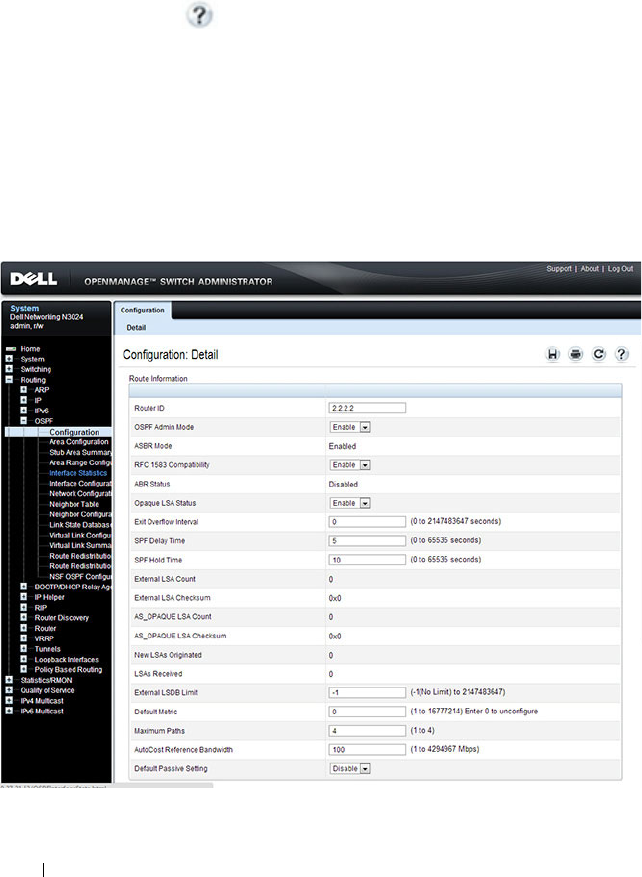
1122 Configuring OSPF and OSPFv3
Configuring OSPF Features (Web)
This section provides information about the OpenManage Switch
Administrator pages for configuring and monitoring OSPF features on a Dell
Networking N2000, N3000, and N4000 series switches. For details about the
fields on a page, click at the top of the page.
OSPF Configuration
Use the Configuration
page to enable OSPF on a router and to configure the
related OSPF settings.
To display the page, click Routing
→
OSPF
→
Configuration in the
navigation panel.
Figure 35-1. OSPF Configuration
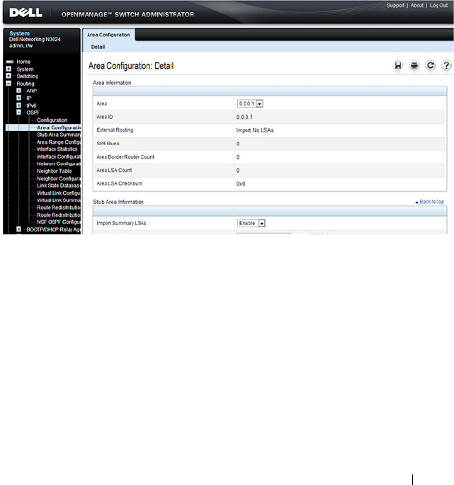
Configuring OSPF and OSPFv3 1123
OSPF Area Configuration
The Area Configuration
page lets you create a Stub area configuration and
NSSA once you’ve enabled OSPF on an interface through Routing
→
OSPF
→
Interface Configuration. At least one router must have OSPF enabled for
this web page to display.
To display the page, click Routing
→
OSPF
→
Area Configuration in the
navigation panel. If a Stub Area has been created, the fields in the Stub Area
Information are available. If a NSSA has been created, the fields in the NSSA
Area Information are available.
Figure 35-2. OSPF Area Configuration
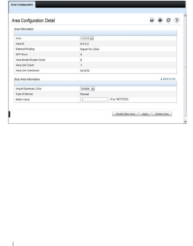
1124 Configuring OSPF and OSPFv3
Configuring an OSPF Stub Area
To configure the area as an OSPF stub area, click Create Stub Area. The
pages refreshes, and displays additional fields that are specific to the stub
area.
Figure 35-3. OSPF Stub Area Configuration
Use the Delete Stub Area button to remove the stub area.
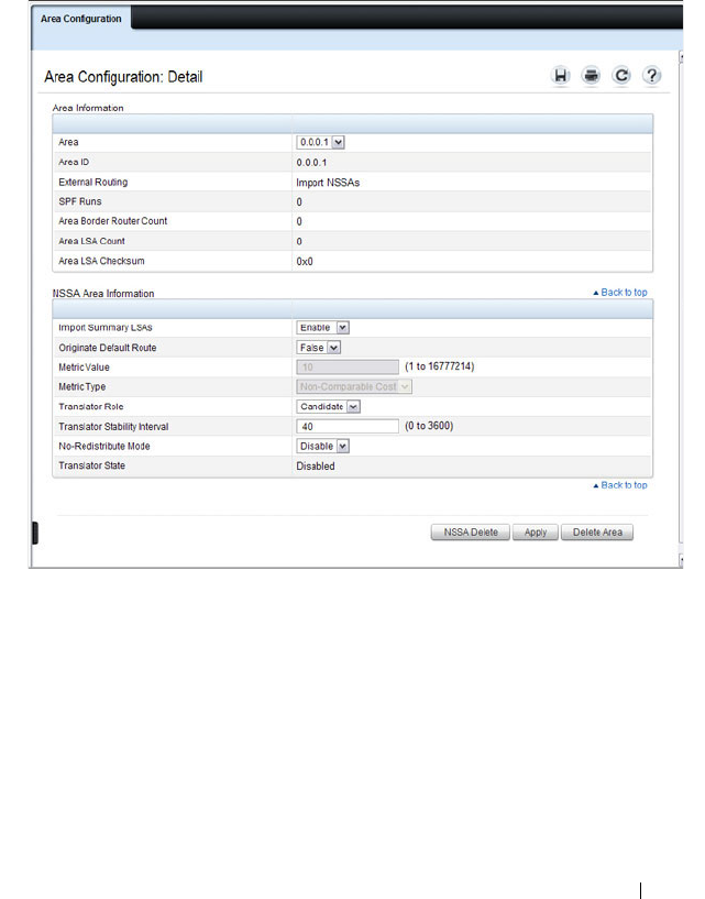
Configuring OSPF and OSPFv3 1125
Configuring an OSPF Not-So-Stubby Area
To configure the area as an OSPF not-so-stubby area (NSSA), click NSSA
Create. The pages refreshes, and displays additional fields that are specific to
the NSSA.
Figure 35-4. OSPF NSSA Configuration
Use the NSSA Delete button to remove the NSSA area.
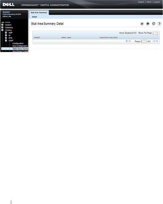
1126 Configuring OSPF and OSPFv3
OSPF Stub Area Summary
The Stub Area Summary page displays OSPF stub area detail.
To display the page, click Routing
→
OSPF
→
Stub Area Summary in the
navigation panel.
Figure 35-5. OSPF Stub Area Summary

Configuring OSPF and OSPFv3 1127
OSPF Area Range Configuration
Use the Area Range Configuration
page to configure and display an area
range for a specified NSSA.
To display the page, click Routing
→
OSPF
→
Area Range Configuration in
the navigation panel.
Figure 35-6. OSPF Area Range Configuration
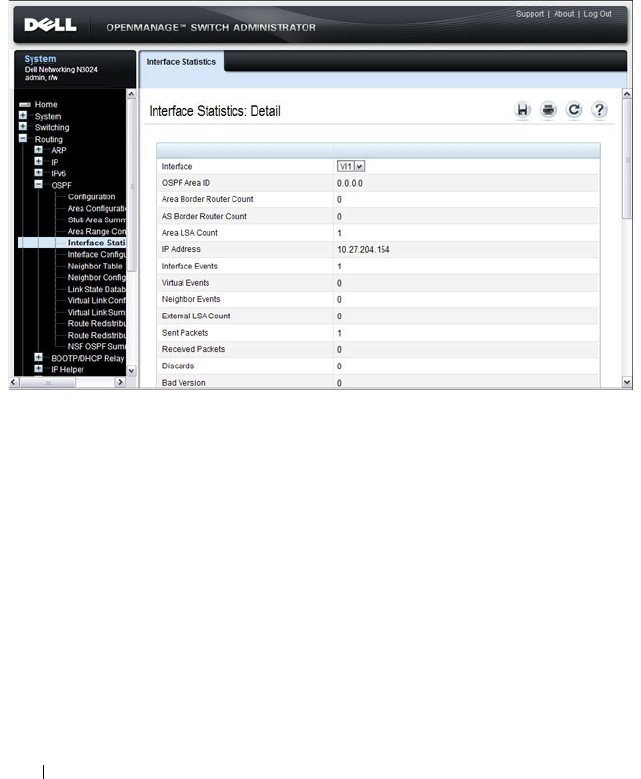
1128 Configuring OSPF and OSPFv3
OSPF Interface Statistics
Use the Interface Statistics
page to display statistics for the selected
interface. The information is displayed only if OSPF is enabled.
To display the page, click Routing
→
OSPF
→
Interface Statistics in the
navigation panel.
Figure 35-7. OSPF Interface Statistics

Configuring OSPF and OSPFv3 1129
OSPF Interface Configuration
Use the Interface Configuration
page to configure an OSPF interface.
To display the page, click Routing
→
OSPF
→
Interface Configuration in
the navigation panel.
Figure 35-8. OSPF Interface Configuration
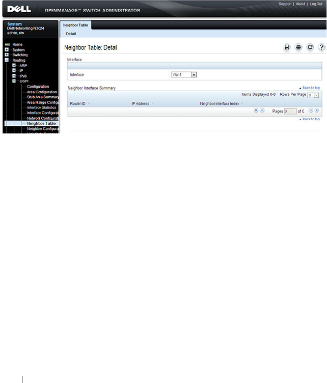
1130 Configuring OSPF and OSPFv3
OSPF Neighbor Table
Use the Neighbor Table
page to display the OSPF neighbor table list. When a
particular neighbor ID is specified, detailed information about a neighbor is
given. The information below is only displayed if OSPF is enabled.
To display the page, click Routing
→
OSPF
→
Neighbor Table in the
navigation panel.
Figure 35-9. OSPF Neighbor Table
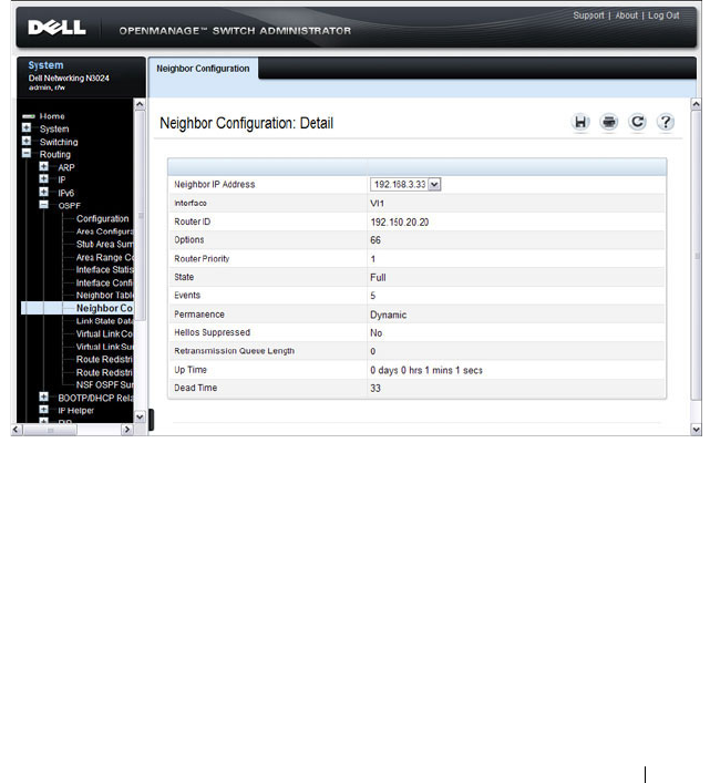
Configuring OSPF and OSPFv3 1131
OSPF Neighbor Configuration
Use the Neighbor Configuration
page to display the OSPF neighbor
configuration for a selected neighbor ID. When a particular neighbor ID is
specified, detailed information about a neighbor is given. The information
below is only displayed if OSPF is enabled and the interface has a neighbor.
The IP address is the IP address of the neighbor.
To display the page, click Routing
→
OSPF
→
Neighbor Configuration in
the navigation panel.
Figure 35-10. OSPF Neighbor Configuration
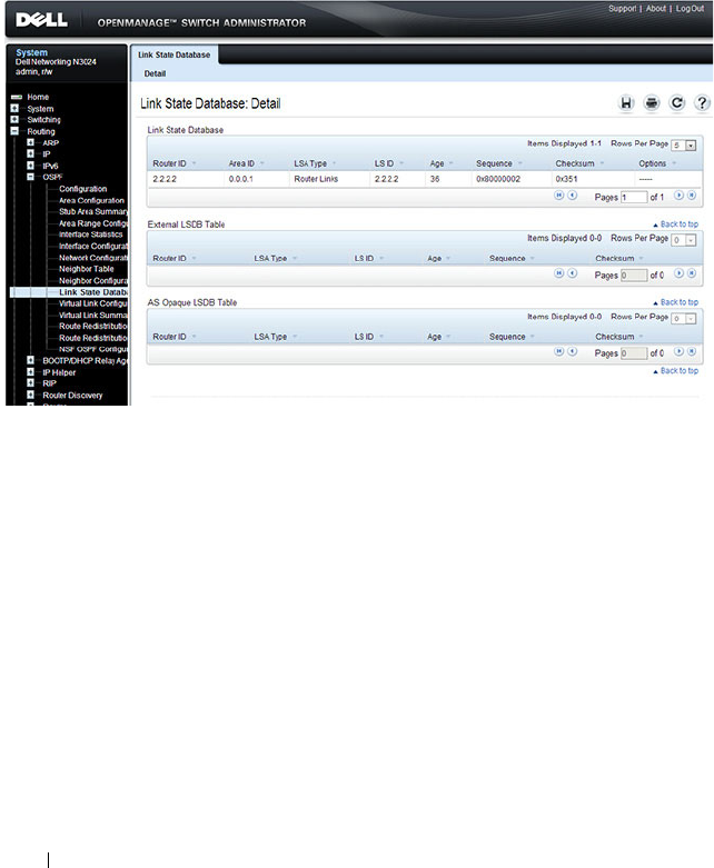
1132 Configuring OSPF and OSPFv3
OSPF Link State Database
Use the Link State Database
page to display OSPF link state, external LSDB
table, and AS opaque LSDB table information.
To display the page, click Routing
→
OSPF
→
Link State Database in the
navigation panel.
Figure 35-11. OSPF Link State Database
OSPF Virtual Link Configuration
Use the Virtual Link Configuration
page to create or configure virtual
interface information for a specific area and neighbor. A valid OSPF area
must be configured before this page can be displayed.
To display the page, click Routing
→
OSPF
→
Virtual Link Configuration in
the navigation panel.
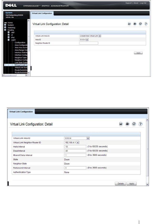
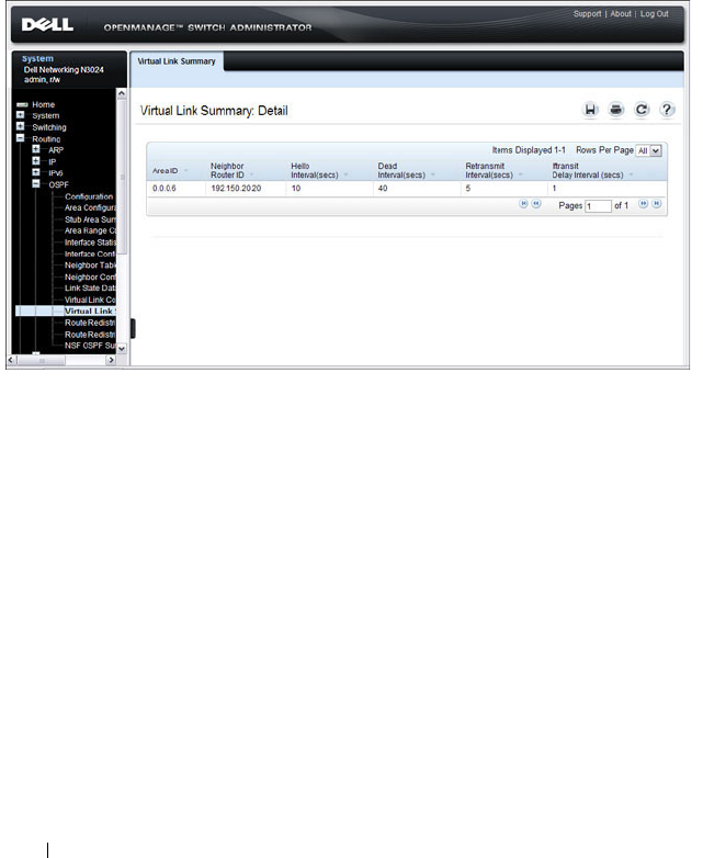
1134 Configuring OSPF and OSPFv3
OSPF Virtual Link Summary
Use the Virtual Link Summary
page to display all of the configured virtual
links.
To display the page, click Routing
→
OSPF
→
Virtual Link Summary in the
navigation panel.
Figure 35-14. OSPF Virtual Link Summary
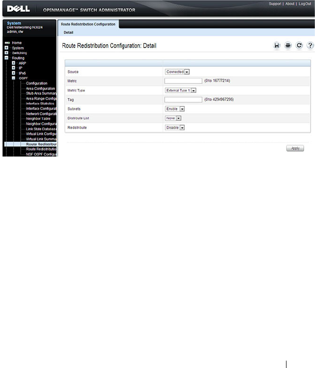
Configuring OSPF and OSPFv3 1135
OSPF Route Redistribution Configuration
Use the Route Redistribution Configuration
page to configure redistribution
in OSPF for routes learned through various protocols. You can choose to
redistribute routes learned from all available protocols or from selected ones.
To display the page, click Routing
→
OSPF
→
Route Redistribution
Configuration in the navigation panel.
Figure 35-15. OSPF Route Redistribution Configuration
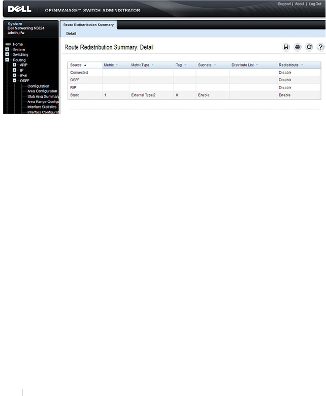
1136 Configuring OSPF and OSPFv3
OSPF Route Redistribution Summary
Use the Route Redistribution Summary
page to display OSPF Route
Redistribution configurations.
To display the page, click Routing
→
OSPF
→
Route Redistribution
Summary in the navigation panel.
Figure 35-16. OSPF Route Redistribution Summary
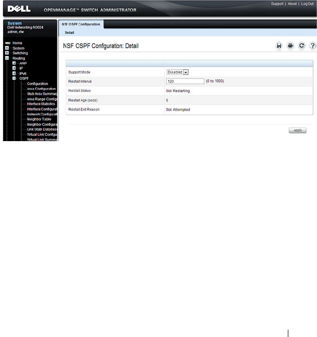
Configuring OSPF and OSPFv3 1137
NSF OSPF Configuration
Use the NSF OSPF Configuration
page to configure the non-stop forwarding
(NSF) support mode and to view NSF summary information for the OSPF
feature. NSF is a feature used in switch stacks to maintain switching and
routing functions in the event of a stack unit failure. For information about
NSF, see "What is Nonstop Forwarding?" on page 178 in the Managing a
Switch Stack chapter.
To display the page, click Routing
→
OSPF
→
NSF OSPF Configuration in
the navigation panel.
Figure 35-17. NSF OSPF Configuration
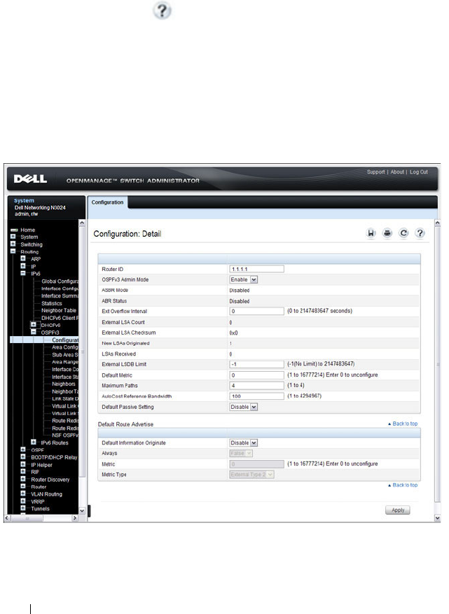
1138 Configuring OSPF and OSPFv3
Configuring OSPFv3 Features (Web)
This section provides information about the OpenManage Switch
Administrator pages for configuring and monitoring OSPFv3 features on a
Dell Networking N2000, N3000, and N4000 series switches. For details about
the fields on a page, click at the top of the page.
OSPFv3 Configuration
Use the Configuration
page to activate and configure OSPFv3 for a switch.
To display the page, click IPv6
→
OSPFv3
→
Configuration in the
navigation panel.
Figure 35-18. OSPFv3 Configuration
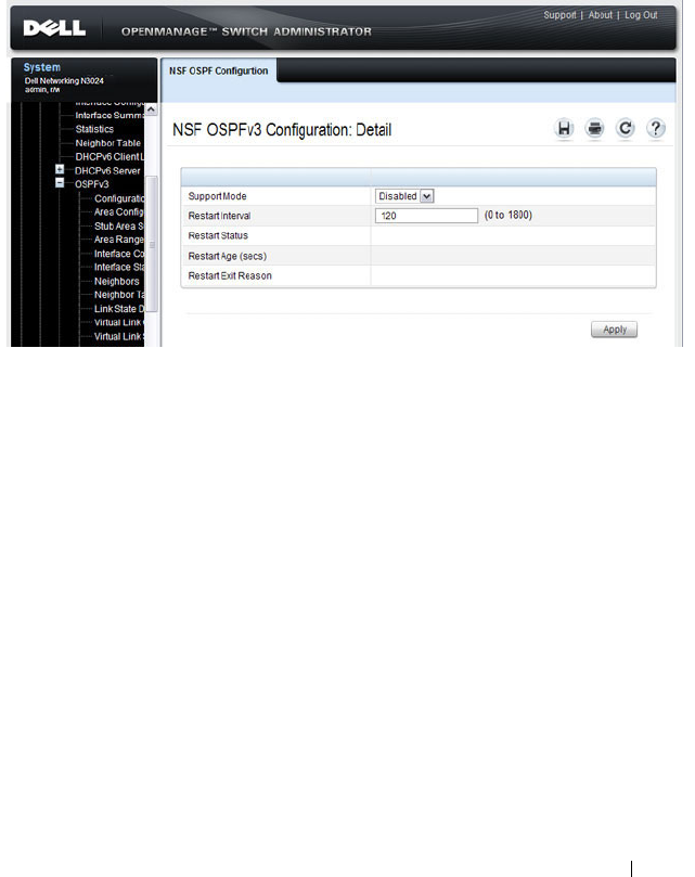
Configuring OSPF and OSPFv3 1139
OSPFv3 Area Configuration
Use the Area Configuration
page to create and configure an OSPFv3 area.
To display the page, click IPv6
→
OSPFv3
→
Area Configuration in the
navigation panel.
Figure 35-19. OSPFv3 Area Configuration
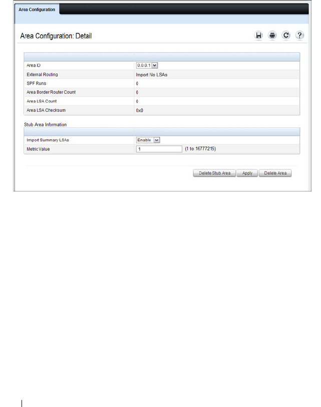
1140 Configuring OSPF and OSPFv3
Configuring an OSPFv3 Stub Area
To configure the area as an OSPFv3 stub area, click Create Stub Area. The
pages refreshes, and displays additional fields that are specific to the stub
area.
Figure 35-20. OSPFv3 Stub Area Configuration
Use the Delete Stub Area button to remove the stub area.

Configuring OSPF and OSPFv3 1141
Configuring an OSPFv3 Not-So-Stubby Area
To configure the area as an OSPFv3 not-so-stubby area (NSSA), click Create
NSSA. The pages refreshes, and displays additional fields that are specific to
the NSSA.
Figure 35-21. OSPFv3 NSSA Configuration
Use the Delete NSSA button to remove the NSSA area.
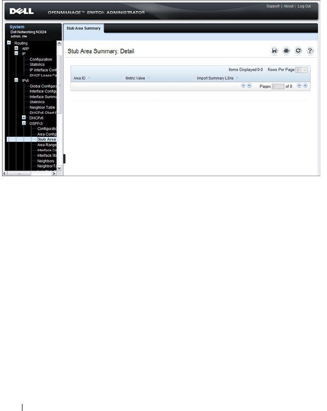
1142 Configuring OSPF and OSPFv3
OSPFv3 Stub Area Summary
Use the Stub Area Summary
page to display OSPFv3 stub area detail.
To display the page, click IPv6
→
OSPFv3
→
Stub Area Summary in the
navigation panel.
Figure 35-22. OSPFv3 Stub Area Summary
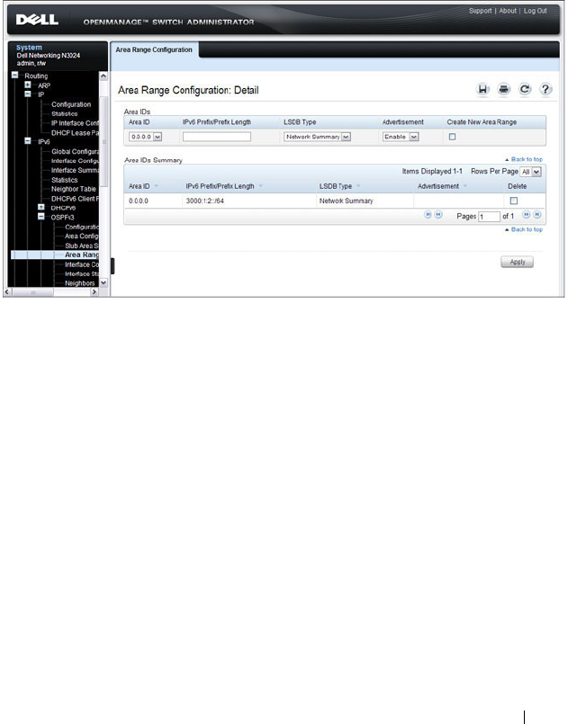
Configuring OSPF and OSPFv3 1143
OSPFv3 Area Range Configuration
Use the Area Range Configuration
page to configure OSPFv3 area ranges.
To display the page, click IPv6
→
OSPFv3
→
Area Range Configuration in
the navigation panel.
Figure 35-23. OSPFv3 Area Range Configuration
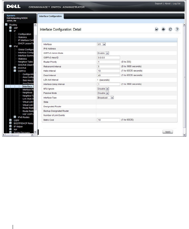
1144 Configuring OSPF and OSPFv3
OSPFv3 Interface Configuration
Use the Interface Configuration
page to create and configure OSPFv3
interfaces.
To display the page, click IPv6
→
OSPFv3
→
Interface Configuration in the
navigation panel.
Figure 35-24. OSPFv3 Interface Configuration
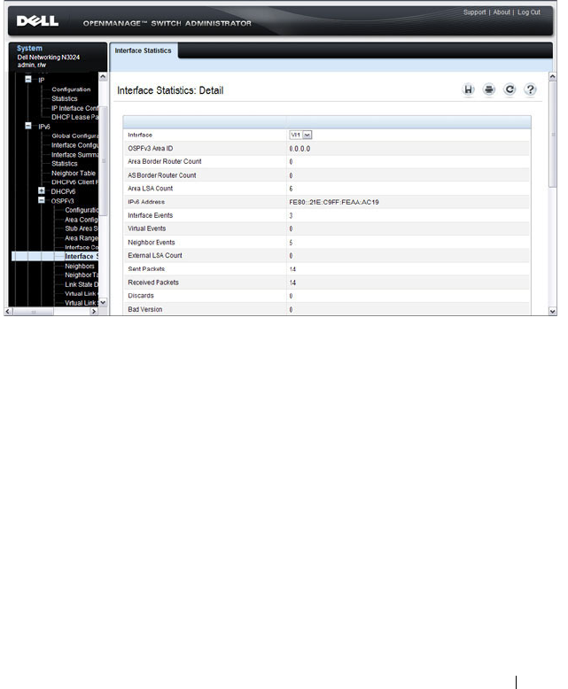
Configuring OSPF and OSPFv3 1145
OSPFv3 Interface Statistics
Use the Interface Statistics
page to display OSPFv3 interface statistics.
Information is only displayed if OSPF is enabled.
To display the page, click IPv6
→
OSPFv3
→
Interface Statistics in the
navigation panel.
Figure 35-25. OSPFv3 Interface Statistics
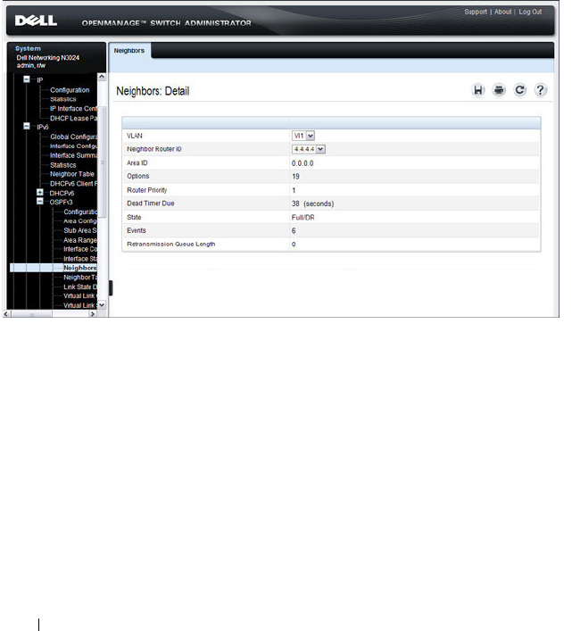
1146 Configuring OSPF and OSPFv3
OSPFv3 Neighbors
Use the Neighbors
page to display the OSPF neighbor configuration for a
selected neighbor ID. When a particular neighbor ID is specified, detailed
information about that neighbor is given. Neighbor information only displays
if OSPF is enabled and the interface has a neighbor. The IP address is the IP
address of the neighbor.
To display the page, click IPv6
→
OSPFv3
→
Neighbors in the navigation
panel.
Figure 35-26. OSPFv3 Neighbors
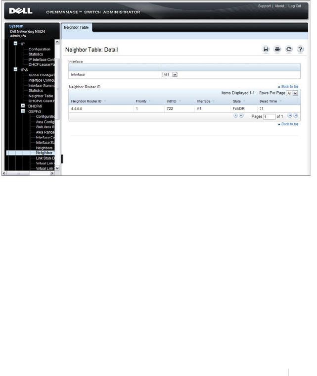
Configuring OSPF and OSPFv3 1147
OSPFv3 Neighbor Table
Use the Neighbor Table
page to display the OSPF neighbor table list. When a
particular neighbor ID is specified, detailed information about a neighbor is
given. The neighbor table is only displayed if OSPF is enabled.
To display the page, click IPv6
→
OSPFv3
→
Neighbor Table in the
navigation panel.
Figure 35-27. OSPFv3 Neighbor Table
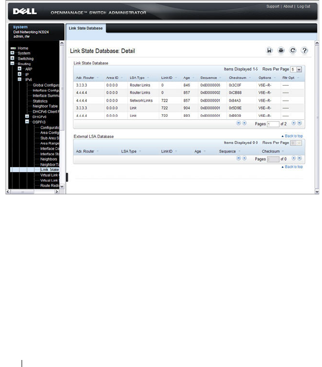
1148 Configuring OSPF and OSPFv3
OSPFv3 Link State Database
Use the Link State Database
page to display the link state and external LSA
databases. The OSPFv3 Link State Database
page has been updated to
display external LSDB table information in addition to OSPFv3 link state
information.
To display the page, click IPv6
→
OSPFv3
→
Link State Database in the
navigation panel.
Figure 35-28. OSPFv3 Link State Database
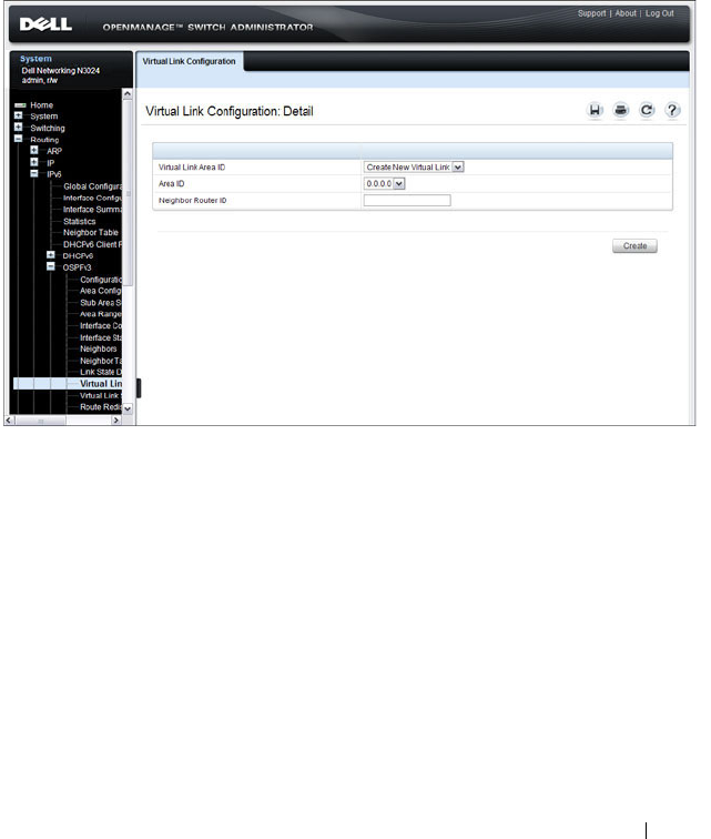
Configuring OSPF and OSPFv3 1149
OSPFv3 Virtual Link Configuration
Use the Virtual Link Configuration
page to define a new or configure an
existing virtual link. To display this page, a valid OSPFv3 area must be
defined through the OSPFv3 Area Configuration page.
To display the page, click IPv6
→
OSPFv3
→
Virtual Link Configuration in
the navigation panel.
Figure 35-29. OSPFv3 Virtual Link Configuration

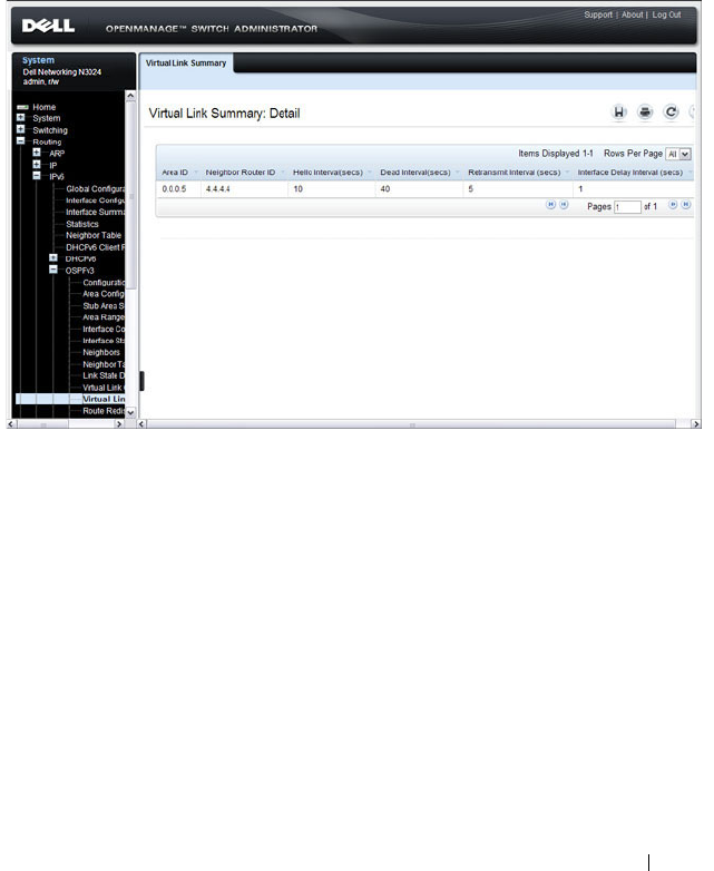
Configuring OSPF and OSPFv3 1151
OSPFv3 Virtual Link Summary
Use the Virtual Link Summary
page to display virtual link data by Area ID
and Neighbor Router ID.
To display the page, click IPv6
→
OSPFv3
→
Virtual Link Summary in the
navigation panel.
Figure 35-31. OSPFv3 Virtual Link Summary

1152 Configuring OSPF and OSPFv3
OSPFv3 Route Redistribution Configuration
Use the Route Redistribution Configuration
page to configure route
redistribution.
To display the page, click IPv6
→
OSPFv3
→
Route Redistribution
Configuration in the navigation panel.
Figure 35-32. OSPFv3 Route Redistribution Configuration
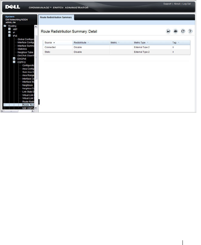
Configuring OSPF and OSPFv3 1153
OSPFv3 Route Redistribution Summary
Use the Route Redistribution Summary
page to display route redistribution
settings by source.
To display the page, click IPv6
→
OSPFv3
→
Route Redistribution
Summary in the navigation panel.
Figure 35-33. OSPFv3 Route Redistribution Summary
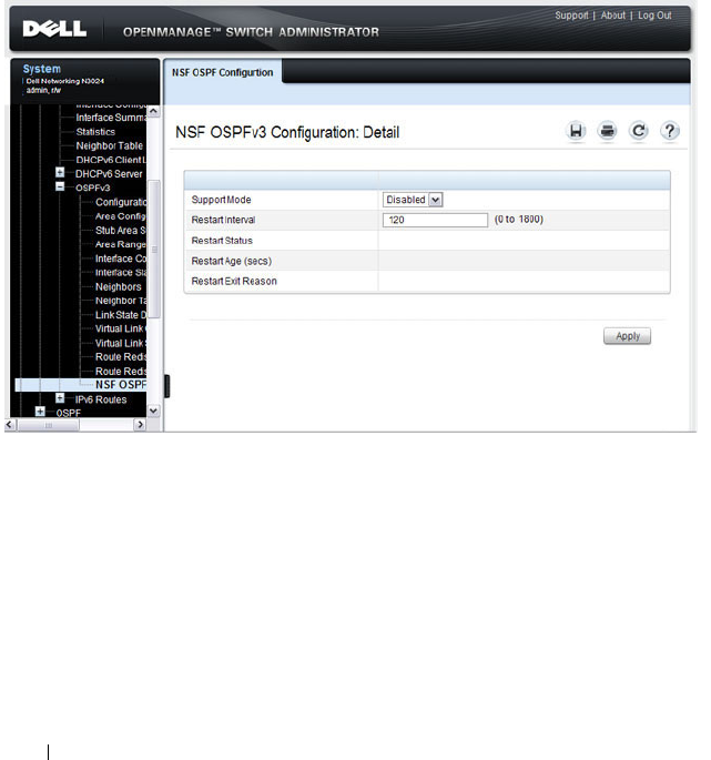
1154 Configuring OSPF and OSPFv3
NSF OSPFv3 Configuration
Use the NSF OSPFv3 Configuration page to configure the non-stop
forwarding (NSF) support mode and to view NSF summary information for
the OSPFv3 feature. NSF is a feature used in switch stacks to maintain
switching and routing functions in the event of a stack unit failure. For
information about NSF, see "What is Nonstop Forwarding?" on page 178 in
the Managing a Switch Stack chapter.
To display the page, click Routing
→
OSPFv3
→
NSF OSPFv3
Configuration in the navigation panel.
Figure 35-34. NSF OSPFv3 Configuration

Configuring OSPF and OSPFv3 1155
Configuring OSPF Features (CLI)
This section provides information about the commands you use to configure
and view OSPF settings on the switch. This section does not describe all
available show commands. For more information about all available OSPF
commands, see the
Dell Networking N2000, N3000, and N4000 Series
Switches CLI Reference Guide
at support.dell.com/manuals.
Configuring Global OSPF Settings
Beginning in Privileged EXEC mode, use the following commands to
configure various global OSPF settings for the switch.
Command Purpose
configure Enter global configuration mode.
router ospf Enter OSPF configuration mode.
router-id
ip-address
Set the 4-digit dotted-decimal number that uniquely
identifies the router.
auto-cost reference-
bandwidth
ref_bw
Set the reference bandwidth used in the formula to
compute link cost for an interface:
link cost = ref_bw÷interface bandwidth
The
ref_bw
variable is the reference bandwidth in Mbps
(Range: 1–4294967).
capability opaque Allow OSPF to store and flood opaque LSAs. An opaque
LSA is used for flooding user defined information within
an OSPF router domain.
compatible rfc1583 (Optional) Enable compatibility with RFC 1583.
If all OSPF routers in the routing domain are capable of
operating according to RFC 2328, OSPF 1583
compatibility mode should be disabled.

1156 Configuring OSPF and OSPFv3
default-information
originate [always]
[metric
metric-value
]
[metric-type
type-value
]
Control the advertisement of default routes.
•
always
— Normally, OSPF originates a default route only
if a default route is redistributed into OSPF (and default-
information originate is configured). When the always
option is configured, OSPF originates a default route,
even if no default route is redistributed.
•
metric-value
— The metric (or preference) value of the
default route. (Range: 1–16777214)
•
type-value
— The value is either 1 or 2: External type-1
route or External type-2 route.
default-metric
metric-
value
Set a default for the metric of distributed routes (Range:
1–16777214).
distance ospf {external |
inter-area | intra-area }
distance
Set the preference values of OSPF route types in the
router.
The range for the
distance
variable is 1–255. Lower route
preference values are preferred when determining the best
route.
enable Enable OSPF.
exit-overflow-interval
seconds
Specify the exit overflow interval for OSPF as defined in
RFC 1765.
The interval is the number of seconds after entering
overflow state that a router will wait before attempting to
leave the overflow state. (Range: 0–2147483647)
external-lsdb-limit
limit
Configure the external LSDB limit for OSPF as defined in
RFC 1765. If the value is –1, then there is no limit.
The
limit
variable is the maximum number of non-default
AS external-LSAs allowed in the router's link-state
database. (Range: 1 to 2147483647)
maximum-paths
integer
Set the number of paths that OSPF can report for a given
destination (Range: 1–4).
Command Purpose

Configuring OSPF and OSPFv3 1157
passive-interface default Configure OSPF interfaces as passive by default.
This command overrides any interface-level passive mode
settings.OSPF does not form adjacencies on passive
interfaces but does advertise attached networks as stub
networks.
timers spf
delay-time
hold-time
Specify the SPF delay and hold time.
•
delay-time
— SPF delay time. (Range: 0–65535 seconds)
•
hold-time
— SPF hold time. (Range: 0–65535 seconds)
exit Exit to Global Configuration mode.
exit Exit to Privileged EXEC mode.
show ip ospf View OSPF global configuration and status.
show ip ospf statistics View OSPF routing table calculation statistics.
clear ip ospf
[{
configuration
|
redistribution
|
counters
|
neighbor
[
interface
vlan
vlan-id
[
neighbor-id
]]}]
Reset specific OSPF states. If no parameters are specified,
OSPF is disabled and then re-enabled.
Command Purpose

1158 Configuring OSPF and OSPFv3
Configuring OSPF Interface Settings
Beginning in Privileged EXEC mode, use the following commands to
configure per-interface OSPF settings.
Command Purpose
configure Enter global configuration mode.
interface vlan
vlan-id
Enter Interface Configuration mode for the specified
VLAN.
ip ospf area
area-id
[secondaries none]
Enables OSPFv2 on the interface and sets the area ID of
an interface. This command supersedes the effects of
network area command.
The
area-id
variable is the ID of the area (Range: IP
address or decimal from 0 –4294967295)
Use the secondaries none keyword to prevent the interface
from advertising its secondary addresses into the OSPFv2
domain.
ip ospf priority
number-
value
Set the OSPF priority for the interface. The
number-value
variable specifies the priority of an interface (Range: 0 to
255).
The default priority is 1, which is the highest router
priority. A value of 0 indicates that the router is not
eligible to become the designated router on this network.
ip ospf retransmit-
interval
seconds
Set the OSPF retransmit interval for the interface.
The
seconds
variable is the number of seconds between
link-state advertisements for adjacencies belonging to this
router interface.
This value is also used when retransmitting database
descriptions and link-state request packets. Valid values
range from 0 to 3600 seconds (1 hour).
ip ospf hello-interval
seconds
Set the OSPF hello interval for the interface. This
parameter must be the same for all routers attached to a
network.
The
seconds
variable indicates the number of seconds to
wait before sending Hello packets from the interface.
(Range: 1–65535).

Configuring OSPF and OSPFv3 1159
ip ospf dead-interval
seconds
Set the OSPF dead interval for the interface.
The
seconds
variable indicates the number of seconds a
router waits to see a neighbor router's Hello packets before
declaring that the router is down (Range: 1–65535).
This parameter must be the same for all routers attached
to a network. This value should be some multiple of the
Hello Interval.
ip ospf transmit-delay
seconds
Set the OSPF Transit Delay for the interface.
The
seconds
variable sets the estimated number of
seconds it takes to transmit a link state update packet over
this interface. (Range: 1–3600 seconds)
ip ospf mtu-ignore Disable OSPF MTU mismatch detection on the received
database description.
ip ospf network
{broadcast | point-to-
point}
Set the OSPF network type on the interface to broadcast
or point-to-point. OSPF selects a designated router and
originates network LSAs only for broadcast networks. No
more than two OSPF routers may be present on a point-
to-point link.
ip ospf authentication
{none | {simple
key
} |
{encrypt
key key-id
}}
Set the OSPF Authentication Type and Key for the
specified interface.
•
encrypt
— MD5 encrypted authentication key.
•
key
— Authentication key for the specified interface.
(Range: 8 bytes or less if the authentication type is
simple
and 16 bytes or less if the type is
encrypt
.)
•
key-id
— Authentication key identifier for the
authentication type
encrypt
. (Range: 0–25)
ip ospf cost
interface-
cost
Set the metric cost of the interface.
The
interface-cost
variable specifies the cost (link-state
metric) of the OSPF interface. (Range: 1–65535)
bandwidth
bw
Set the interface bandwidth used in the formula to
compute link cost for an interface:
link cost = ref_bw÷interface bandwidth
The
bw
variable is the interface bandwidth (Range:
1–10000000 Kbps).
Command Purpose

1160 Configuring OSPF and OSPFv3
Configuring Stub Areas and NSSAs
Beginning in Privileged EXEC mode, use the following commands to
configure OSPF stub areas and NSSAs.
exit Exit to Global Configuration Mode
router ospf Enter OSPF configuration mode.
passive-interface vlan
vlan-id
Make an interface passive to prevent OSPF from forming
an adjacency on an interface. OSPF advertises networks
attached to passive interfaces as stub networks.
network
ip-address
wildcard-mask
area
area-
id
Enable OSPFv2 on interfaces whose primary IP address
matches this command, and make the interface a member
of the specified area.
•
ip-address
— Base IPv4 address of the network area.
•
wildcard-mask
— The network mask indicating the
subnet.
•
area-id
— The ID of the area (Range: IP address or
decimal from 0–4294967295).
exit Exit to Global Config mode.
exit Exit to Privileged EXEC mode.
show ip ospf interface
[vlan
vlan-id
]
View summary information for all OSPF interfaces
configured on the switch or for the specified routing
interface.
show ip ospf interface
stats vlan
vlan-id
View per-interface OSPF statistics.
Command Purpose
configure Enter global configuration mode.
router ospf Enter OSPF configuration mode.
area
area-id
stub Create a stub area for the specified area ID.
area
area-id
stub no-
summary
Prevent Summary LSAs from being advertised into the
stub area.
Command Purpose

Configuring OSPF and OSPFv3 1161
area
area-id
default-cost
integer
Configure the metric value (default cost) for the type 3
summary LSA sent into the stub area. Range:
1–16777215)
area
area-id
nssa Create an NSSA for the specified area ID.
area
area-id
nssa no-
summary
Configure the NSSA so that summary LSAs are not
advertised into the NSSA.
area
area-id
nssa
translator-role {always |
candidate}
Configure the translator role of the NSSA.
•
always
— The router assumes the role of the translator
when it becomes a border router.
•
candidate
— The router can participate in the translator
election process when it attains border router status.
area
area-id
nssa
translator-stab-intv
integer
Configure the translator stability interval of the NSSA.
The
integer
variable is the period of time that an elected
translator continues to perform its duties after it
determines that its translator status has been deposed by
another router. (Range: 0–3600)
area
area-id
nssa default-
information-originate
[metric
metric-value
]
[metric-type
metric-type-
value
]
Configure the metric value and type for the default route
advertised into the NSSA. The metric type can be
comparable (nssa-external 1) or non-comparable (nssa-
external 2).
area
area-id
nssa
no-redistribution
Prevent learned external routes from being redistributed
to the NSSA.
exit Exit to Global Config mode.
exit Exit to Privileged EXEC mode.
show ip ospf area
area-id
View the configuration and status of an OSPF area.
Command Purpose

1162 Configuring OSPF and OSPFv3
Configuring Virtual Links
Beginning in Privileged EXEC mode, use the following commands to
configure OSPF Virtual Links.
Command Purpose
configure Enter global configuration mode.
router ospf Enter OSPF configuration mode.
area
area-id
virtual-link
neighbor-id
Create the OSPF virtual interface for the specified area-
id and neighbor router. The
neighbor-id
variable is the IP
address of the neighboring router.
area
area-id
virtual-link
router-id
[authentication
[message-digest | null]]
[[authentication-key
key
]
| [message-digest-key
key-
id
md5
key
]]
Create the OSPF virtual interface for the specified area-
id and neighbor router.
Use the optional parameters to configure authentication
for the virtual link. If the area has not been previously
created, it is created by this command. If the area already
exists, the virtual-link information is added or modified.
•
authentication
—Specifies authentication type.
•
message-digest
—Specifies that message-digest
authentication is used.
•
null
—No authentication is used. Overrides password or
message-digest authentication if configured for the
area.
•
md5
—Use MD5 Encryption for an OSPF Virtual Link
•
key
—Authentication key for the specified interface.
(Range: 8 bytes or less if the authentication type is
simple and 16 bytes or less if the type is encrypt.)
•
key-id
—Authentication key identifier for the
authentication type encrypt. (Range: 0-255)
area
area-id
virtual-link
neighbor-id
retransmit-
interval
seconds
Set the OSPF retransmit interval for the virtual link
interface.
The
seconds
variable is the number of seconds to wait
between retransmitting LSAs if no acknowledgement is
received. (Range: 0–3600)

Configuring OSPF and OSPFv3 1163
area
area-id
virtual-link
neighbor-id
hello-interval
seconds
Set the OSPF hello interval for the virtual link.
The
seconds
variable indicates the number of seconds to
wait before sending Hello packets from the virtual
interface. (Range: 1–65535).
area
area-id
virtual-link
neighbor-id
dead-interval
seconds
Set the OSPF dead interval for the virtual link.
The
seconds
variable indicates the number of seconds to
wait before the virtual interface is assumed to be dead.
(Range: 1–65535)
area
area-id
virtual-link
neighbor-id
transmit-
delay
seconds
Set the OSPF Transit Delay for the interface.
The
seconds
variable is the number of seconds to
increment the age of the LSA before sending, based on
the estimated time it takes to transmit from the
interface. (Range: 0–3600)
exit Exit to Global Config mode.
exit Exit to Privileged EXEC mode.
show ip ospf virtual-link
brief
View summary information about all virtual links
configured on the switch.
Command Purpose

1164 Configuring OSPF and OSPFv3
Configuring OSPF Area Range Settings
Beginning in Privileged EXEC mode, use the following commands to
configure an OSPF area range.
Configuring OSPF Route Redistribution Settings
Beginning in Privileged EXEC mode, use the following commands to
configure OSPF route redistribution settings.
Command Purpose
configure Enter global configuration mode.
router ospf Enter OSPF configuration mode.
area
area-id
range
ip-address mask
{summarylink |
nssaexternallink}
[advertise
|not-advertise]
Configure a summary prefix for routes learned in a given area.
•
area-id
— Identifies the OSPF NSSA to configure. (Range: IP
address or decimal from 0–4294967295)
•
ip-address
— IP address.
•
subnet-mask
— Subnet mask associated with IP address.
•
summarylink
— Specifies a summary link LSDB type.
•
nssaexternallink
— Specifies an NSSA external link LSDB
type.
•
advertise
— Advertisement of the area range.
•
not-advertise
— Suppresses advertisement of the area range.
exit Exit to Global Config mode.
exit Exit to Privileged EXEC mode.
show ip ospf range
area-id
View information about the area ranges for the specified
area-id
.
Command Purpose
configure Enter global configuration mode.
router ospf Enter OSPF configuration mode.

Configuring OSPF and OSPFv3 1165
distribute-list
accesslistname
out {rip |
static | connected}
Specify the access list to filter routes received from the
source protocol. The ACL must already exist on the
switch. For information about the commands you use to
configure ACLs, see "Configuring ACLs (CLI)" on
page 612.
•
accesslistname
— The name used to identify an existing
ACL.
•
rip
— Apply the specified access list when RIP is the
source protocol.
•
static
— Apply the specified access list when packets
come through the static route.
•
connected
— Apply the specified access list when
packets come from a directly connected route.
redistribute {rip | static |
connected} [metric
integer
] [metric-type {1 |
2}] [tag
integer
] [subnets]
Configure OSPF to allow redistribution of routes from
the specified source protocol/routers.
•
rip
— Specifies RIP as the source protocol.
•
static
— Specifies that the source is a static route.
•
connected
— Specifies that the source is a directly
connected route.
•
metric
— Specifies the metric to use when
redistributing the route. (Range: 0–16777214)
•
metric-type 1
— Type 1 external route.
•
metric-type 2
— Type 2 external route.
•
tag
— Value attached to each external route. (Range:
0–4294967295)
•
subnets
—Unless this keyword is configured, OSPF
distributes only class A, class B, and class C prefixes.
exit Exit to Global Config mode.
exit Exit to Privileged EXEC mode.
show ip ospf View OSPF configuration and status information,
including route distribution information.
Command Purpose

1166 Configuring OSPF and OSPFv3
Configuring NSF Settings for OSPF
Beginning in Privileged EXEC mode, use the following commands to
configure the non-stop forwarding settings for OSPF.
Command Purpose
configure Enter global configuration mode.
router ospf Enter OSPF configuration mode.
nsf [ietf ] helper strict-lsa-
checking
Require that an OSPF helpful neighbor exit helper mode
whenever a topology change occurs. Use the ietf keyword
to distinguish the IETF standard implementation of
graceful restart from other implementations.
nsf [ietf ] restart-interval
seconds
Configure the length of the grace period on the restarting
router.
The
seconds
keyword is the number of seconds that the
restarting router asks its neighbors to wait before exiting
helper mode. The restarting router includes the restart
interval in its grace LSAs (range 1–1800 seconds)
nsf helper [planned-only] Allow OSPF to act as a helpful neighbor for a restarting
router. Include the planned-only keyword to indicate
that OSPF should only help a restarting router
performing a planned restart.
nsf [ietf] [planned-only] Enable a graceful restart of OSPF.
•
ietf
— This keyword is used to distinguish the IETF
standard implementation of graceful restart from other
implementations. Since the IETF implementation is
the only one supported, this keyword is optional.
•
planned-only
— This keyword indicates that OSPF
should only perform a graceful restart when the restart is
planned (i.e., when the restart is a result of the initiate
failover command).

Configuring OSPF and OSPFv3 1167
Configuring OSPFv3 Features (CLI)
This section provides information about the commands you use to configure
OSPFv3 settings on the switch. For more information about the commands
and about additional show commands, see the
Dell Networking N2000,
N3000, and N4000 Series Switches CLI Reference Guide
at
support.dell.com/manuals.
Configuring Global OSPFv3 Settings
Beginning in Privileged EXEC mode, use the following commands to
configure various global OSPFv3 settings for the switch.
Command Purpose
configure Enter global configuration mode.
ipv6 router ospf Enter OSPFv3 configuration mode.
router-id
ip-address
Set the 4-digit dotted-decimal number that uniquely
identifies the router.
auto-cost reference-
bandwidth
ref_bw
Set the reference bandwidth used in the formula to
compute link cost for an interface:
link cost = ref_bw÷interface bandwidth
The
ref_bw
variable is the reference bandwidth in Mbps
(Range: 1–4294967).
default-information
originate [always]
[metric
metric-value
]
[metric-type
type-value
]
Control the advertisement of default routes.
•
always
— Normally, OSPFv3 originates a default route
only if a default route is redistributed into OSPFv3 (and
default-information originate is configured). When the
always option is configured, OSPFv3 originates a default
route, even if no default route is redistributed.
•
metric-value
— The metric (or preference) value of the
default route. (Range: 1–16777214)
•
type-value
— The value is either 1 or 2: External type-1
route or External type-2 route.
default-metric
metric-
value
Set a default for the metric of distributed routes. (Range:
1–16777214).

1168 Configuring OSPF and OSPFv3
distance ospf {external |
inter-area | intra-area }
distance
Set the preference values of OSPFv3 route types in the
router.
The range for the
distance
variable is 1–255. Lower route
preference values are preferred when determining the best
route.
enable Enable OSPFv3.
exit-overflow-interval
seconds
Specify the exit overflow interval for OSPFv3 as defined in
RFC 1765.
The interval is the number of seconds after entering
overflow state that a router will wait before attempting to
leave the overflow state. (Range: 0–2147483647)
external-lsdb-limit
limit
Configure the external LSDB limit for OSPFv3 as defined
in RFC 1765. If the value is -1, then there is no limit.
The
limit
variable is the maximum number of non-default
AS external-LSAs allowed in the router's link-state
database. (Range: –1 to 2147483647)
maximum-paths
maxpaths
Set the number of paths that OSPFv3 can report for a
given destination. (Range: 1–4.)
passive-interface default Configure OSPFv3 interfaces as passive by default. This
command overrides any interface-level passive mode
settings.
OSPFv3 does not form adjacencies on passive interfaces
but does advertise attached networks as stub networks.
exit Exit to Global Configuration mode.
exit Exit to Privileged EXEC mode.
show ipv6 ospf View OSPFv3 global configuration and status.
clear ipv6 ospf
[{configuration |
redistribution | counters
| neighbor [interface
vlan
vlan-id
[
neighbor-id
]]}]
Reset specific OSPFv3 states. If no parameters are
specified, OSPFv3 is disabled and then re-enabled.
Command Purpose

Configuring OSPF and OSPFv3 1169
Configuring OSPFv3 Interface Settings
Beginning in Privileged EXEC mode, use the following commands to
configure per-interface OSPFv3 settings.
Command Purpose
configure Enter global configuration mode.
interface vlan
vlan-id
Enter Interface Configuration mode for the specified
VLAN.
ipv6 ospf areaid
area-id
Enables OSPFv3 on the interface and sets the area ID of
an interface. This command supersedes the effects of
network area command.
The
area-id
variable is the ID of the area (Range: IP
address or decimal from 0 –4294967295)
ipv6 ospf priority
number-value
Set the OSPFv3 priority for the interface. The
number-
value
variable specifies the priority of an interface (Range:
0 to 255).
The default priority is 1, which is the highest router
priority. A value of 0 indicates that the router is not
eligible to become the designated router on this network.
ipv6 ospf retransmit-
interval
seconds
Set the OSPFv3 retransmit interval for the interface.
The
seconds
variable is the number of seconds between
link-state advertisements for adjacencies belonging to this
router interface.
This value is also used when retransmitting database
descriptions and link-state request packets. Valid values
range from 0 to 3600 seconds (1 hour).
ipv6 ospf hello-interval
seconds
Set the OSPFv3 hello interval for the interface. This
parameter must be the same for all routers attached to a
network.
The
seconds
variable indicates the number of seconds to
wait before sending Hello packets from the interface.
(Range: 1–65535).

1170 Configuring OSPF and OSPFv3
ipv6 ospf dead-interval
seconds
Set the OSPFv3 dead interval for the interface.
The
seconds
variable indicates the number of seconds a
router waits to see a neighbor router's Hello packets before
declaring that the router is down (Range: 1–65535).
This parameter must be the same for all routers attached
to a network. This value should be some multiple of the
Hello Interval.
ipv6 ospf transmit-delay
seconds
Set the OSPFv3 Transit Delay for the interface.
The
seconds
variable sets the estimated number of
seconds it takes to transmit a link state update packet over
this interface. (Range: 1–3600 seconds)
ip ospf mtu-ignore Disable OSPFv3 MTU mismatch detection on received
database description packets.
ipv6 ospf network
{broadcast | point-to-
point }
Set the OSPFv3 network type on the interface to
broadcast or point-to-point. OSPFv3 selects a designated
router and originates network LSAs only for broadcast
networks. No more than two OSPFv3 routers may be
present on a point-to-point link.
ipv6 ospf cost
interface-
cost
Set the metric cost of the interface.
The
interface-cost
variable specifies the cost (link-state
metric) of the OSPFv3 interface. (Range: 1–65535)
bandwidth
bw
Set the interface bandwidth used in the formula to
compute link cost for an interface:
link cost = ref_bw÷interface bandwidth
The
bw
variable is the interface bandwidth (Range:
1–10000000 Kbps).
exit Exit to Global Configuration Mode
ipv6 router ospf Enter OSPFv3 configuration mode.
passive-interface {vlan
vlan-id
| tunnel
tunnel-
id
}
Make an interface passive to prevent OSPFv3 from
forming an adjacency on an interface. OSPFv3 advertises
networks attached to passive interfaces as stub networks.
exit Exit to Global Config mode.
exit Exit to Privileged EXEC mode.
Command Purpose

Configuring OSPF and OSPFv3 1171
Configuring Stub Areas and NSSAs
Beginning in Privileged EXEC mode, use the following commands to
configure OSPFv3 stub areas and NSSAs.
show ipv6 ospf interface
[
interface-type interface-
number
]
View summary information for all OSPFv3 interfaces
configured on the switch or for the specified routing
interface.
show ipv6 ospf interface
stats
interface-type
interface-number
View per-interface OSPFv3 statistics.
Command Purpose
configure Enter global configuration mode.
ipv6 router ospf Enter OSPFv3 configuration mode.
area
area-id
stub Create a stub area for the specified area ID.
area
area-id
stub no-
summary
Prevent Summary LSAs from being advertised into the
stub area.
area
area-id
default-cost
cost
Configure the metric value (default cost) for the type 3
summary LSA sent into the stub area. Range:
1–16777215)
Command Purpose

1172 Configuring OSPF and OSPFv3
area
area-id
nssa [no-
redistribution] [default-
information-originate
[metric
metric-value
]
[metric-type
metric-type-
value
]] [no-summary]
[translator-role
role
]
[translator-stab-intv
interval
]
Create and configure an NSSA for the specified area ID.
•
metric-value
—Specifies the metric of the default route
advertised to the NSSA. (Range: 1–16777214)
•
metric-type-value
—The metric type can be one of the
following :
• A metric type of nssa-external 1 (comparable)
• A metric type of nssa-external 2 (non-comparable)
•no-summary—Summary LSAs are not advertised into
the NSSA
•
role
—The translator role where role is one of the
following :
•
always
—The router assumes the role of the translator
when it becomes a border router.
•
candidate
—The router to participate in the translator
election process when it attains border router status.
•
interval
—The period of time that an elected translator
continues to perform its duties after it determines that
its translator status has been deposed by another router.
(Range: 0–3600)
area
area-id
nssa
no-redistribution
Prevent learned external routes from being redistributed
to the NSSA.
exit Exit to Global Config mode.
exit Exit to Privileged EXEC mode.
show ipv6 ospf area
area-
id
Show configuration and status of an OSPF area.
Command Purpose

Configuring OSPF and OSPFv3 1173
Configuring Virtual Links
Beginning in Privileged EXEC mode, use the following commands to
configure OSPFv3 Virtual Links.
Command Purpose
configure Enter global configuration mode.
ipv6 router ospf Enter OSPFv3 configuration mode.
area
area-id
virtual-link
neighbor-id
Create the OSPFv3 virtual interface for the specified
area-id
and neighbor router. The
neighbor-id
variable is
the IP address of the neighboring router.
area
area-id
virtual-link
neighbor-id
retransmit-
interval
seconds
Set the OSPFv3 retransmit interval for the virtual link
interface.
The
seconds
variable is the number of seconds to wait
between retransmitting LSAs if no acknowledgement is
received. (Range: 0–3600)
area
area-id
virtual-link
neighbor-id
hello-interval
seconds
Set the OSPFv3 hello interval for the virtual link.
The
seconds
variable indicates the number of seconds to
wait before sending Hello packets from the virtual
interface. (Range: 1–65535).
area
area-id
virtual-link
neighbor-id
dead-interval
seconds
Set the OSPFv3 dead interval for the virtual link.
The
seconds
variable indicates the number of seconds to
wait before the virtual interface is assumed to be dead.
(Range: 1–65535)
area
area-id
virtual-link
neighbor-id
transmit-
delay
seconds
Set the OSPFv3 Transit Delay for the interface.
The
seconds
variable is the number of seconds to
increment the age of the LSA before sending, based on
the estimated time it takes to transmit from the
interface. (Range: 0–3600)
exit Exit to Global Config mode.
exit Exit to Privileged EXEC mode.
show ipv6 ospf virtual-
link brief
View summary information about all virtual links
configured on the switch.

1174 Configuring OSPF and OSPFv3
Configuring an OSPFv3 Area Range
Beginning in Privileged EXEC mode, use the following commands to
configure an OSPFv3 area range.
Command Purpose
configure Enter global configuration mode.
ipv6 router ospf Enter OSPFv3 configuration mode.
area
area-id
range
ipv6-
prefix/prefix-length
{summarylink |
nssaexternallink}
[advertise |not-advertise]
Configure a summary prefix for routes learned in a given
area.
•
area-id
— Identifies the OSPFv3 NSSA to configure.
(Range: IP address or decimal from 0–4294967295)
•
ipv6-prefix/prefix-length
— IPv6 address and prefix
length.
•
summarylink
— Specifies a summary link LSDB type.
•
nssaexternallink
— Specifies an NSSA external link
LSDB type.
•
advertise
— Advertisement of the area range.
•
not-advertise
— Suppresses advertisement of the area
range.
exit Exit to Global Config mode.
exit Exit to Privileged EXEC mode.
show ipv6 ospf range
area-
id
View information about the area ranges for the specified
area-id.

Configuring OSPF and OSPFv3 1175
Configuring OSPFv3 Route Redistribution Settings
Beginning in Privileged EXEC mode, use the following commands to
configure OSPFv3 route redistribution settings.
Command Purpose
configure Enter global configuration mode.
ipv6 router ospf Enter OSPFv3 configuration mode.
redistribute {static |
connected} [metric
metric
] [metric-type {1 |
2}] [tag
tag
]
Configure OSPFv3 to allow redistribution of routes from
the specified source protocol/routers.
•
static
— Specifies that the source is a static route.
•
connected
— Specifies that the source is a directly
connected route.
•
metric
— Specifies the metric to use when
redistributing the route. (Range: 0–16777214)
•
metric-type 1
— Type 1 external route.
•
metric-type 2
— Type 2 external route.
•
tag
— Value attached to each external route, which
might be used to communicate information between
ASBRs. (Range: 0–4294967295)
exit Exit to Global Config mode.
exit Exit to Privileged EXEC mode.
show ipv6 ospf View OSPFv3 configuration and status information,
including information about redistributed routes.

1176 Configuring OSPF and OSPFv3
Configuring NSF Settings for OSPFv3
Beginning in Privileged EXEC mode, use the following commands to
configure the non-stop forwarding settings for OSPFv3.
Command Purpose
configure Enter global configuration mode.
ipv6 router ospf Enter OSPFv3 configuration mode.
nsf [ietf ] helper strict-lsa-
checking
Require that an OSPFv3 helpful neighbor exit helper
mode whenever a topology change occurs. Use the ietf
keyword to distinguish the IETF standard
implementation of graceful restart from other
implementations.
nsf [ietf ] restart-interval
seconds
Configure the length of the grace period on the restarting
router.
The
seconds
keyword is the number of seconds that the
restarting router asks its neighbors to wait before exiting
helper mode. The restarting router includes the restart
interval in its grace LSAs (range 1–1800 seconds)
nsf helper [planned-only] Allow OSPFv3 to act as a helpful neighbor for a restarting
router. Include the planned-only keyword to indicate
that OSPFv3 should only help a restarting router
performing a planned restart.
nsf [ietf] [planned-only] Enable a graceful restart of OSPFv3.
•
ietf
— This keyword is used to distinguish the IETF
standard implementation of graceful restart from other
implementations. Since the IETF implementation is
the only one supported, this keyword is optional.
•
planned-only
— This keyword indicates that OSPF
should only perform a graceful restart when the restart is
planned (i.e., when the restart is a result of the initiate
failover command).
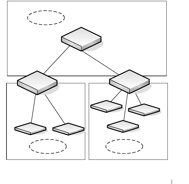
Configuring OSPF and OSPFv3 1177
OSPF Configuration Examples
This section contains the following examples:
• Configuring an OSPF Border Router and Setting Interface Costs
• Configuring Stub and NSSA Areas for OSPF and OSPFv3
• Configuring a Virtual Link for OSPF and OSPFv3
Configuring an OSPF Border Router and Setting Interface Costs
This example shows how to configure the Dell Networking switch as an OSPF
border router. The commands in this example configure the areas and
interfaces on Border Router A shown in Figure 35-35.
Figure 35-35. OSPF Area Border Router
Area 2 Area 3
Area 0 Backbone
Area Internal
Router
Border Router
A
Border Router
B
VLAN 70
192.150.2.2
VLAN 50
192.150.2.1
VLAN 80
192.150.3.1
VLAN 90
192.150.4.1

1178 Configuring OSPF and OSPFv3
To Configure Border Router A:
1
Enable routing on the switch.
console#configure
console(config)#ip routing
2
Create VLANS 70, 80, and 90 and assign them to interfaces.
console(config)#vlan 70,80,90
console(config-vlan70,80,90)#interface gi1/0/1
console(config-if-Gi1/0/1)#switchport access vlan
70
console(config-if-Gi1/0/1)#interface gi1/0/2
console(config-if-Gi1/0/2)#switchport access vlan
80
console(config-if-Gi1/0/1)#interface gi1/0/3
console(config-if-Gi1/0/2)#switchport access vlan
90
3
Assign IP addresses for VLANs 70, 80 and 90.
console(config)#interface vlan 70
console(config-if-vlan70)#ip address 192.150.2.2
255.255.255.0
console(config-if-vlan70)#exit
console(config)#interface vlan 80
console(config-if-vlan80)#ip address 192.150.3.1
255.255.255.0
console(config-if-vlan80)#exit
console(config)#interface vlan 90
console(config-if-vlan90)#ip address 192.150.4.1
255.255.255.0
console(config-if-vlan90)#exit
4
Enable OSPF on the switch and specify a router ID.
console(config)#router ospf
console(config-router)#router-id 192.150.9.9
console(config-router)#exit

Configuring OSPF and OSPFv3 1179
5
Configure the OSPF area ID, priority, and cost for each interface.
console(config)#interface vlan 70
console(config-if-vlan70)#ip ospf area 0.0.0.0
console(config-if-vlan70)#ip ospf priority 128
console(config-if-vlan70)#ip ospf cost 32
console(config-if-vlan70)#exit
console(config)#interface vlan 80
console(config-if-vlan80)#ip ospf area 0.0.0.2
console(config-if-vlan80)#ip ospf priority 255
console(config-if-vlan80)#ip ospf cost 64
console(config-if-vlan80)#exit
console(config)#interface vlan 90
console(config-if-vlan90)#ip ospf area 0.0.0.2
console(config-if-vlan90)#ip ospf priority 255
console(config-if-vlan90)#ip ospf cost 64
console(config-if-vlan90)#exit
NOTE: OSPF is globally enabled by default. To make it operational on the
router, you configure OSPF for particular interfaces and identify which area
the interface is associated with.
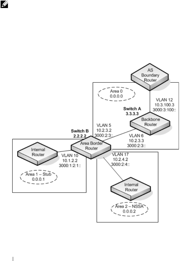
1180 Configuring OSPF and OSPFv3
Configuring Stub and NSSA Areas for OSPF and OSPFv3
In this example, Area 0 connects directly to two other areas: Area 1 is defined
as a stub area and Area 2 is defined as an NSSA area.
Figure 35-36 illustrates this example OSPF configuration.
Figure 35-36. OSPF Configuration—Stub Area and NSSA Area
NOTE: OSPFv2 and OSPFv3 can operate concurrently on a network and on the
same interfaces (although they do not interact). This example configures both
protocols simultaneously.

Configuring OSPF and OSPFv3 1181
Switch A is a backbone router. It links to an ASBR (not defined here) that
routes traffic outside the AS.
To configure Switch A:
1
Globally enable IPv6 and IPv4 routing:
console#configure
console(config)#ipv6 unicast-routing
console(config)#ip routing
2
Create VLANs 6 and 12 and assign them to interfaces.
console(config)#vlan 6,12
console(config-vlan6,12)#interface gi1/0/1
console(config-if-Gi1/0/1)#switchport access vlan
6
console(config-if-Gi1/0/1)#interface gi1/0/2
console(config-if-Gi1/0/2)#switchport access vlan
12
3
Configure IP and IPv6 addresses on VLAN routing interface 6.
console(config-if)#interface vlan 6
console(config-if-vlan6)#ip address 10.2.3.3
255.255.255.0
console(config-if-vlan6)#ipv6 address
3000:2:3::/64 eui64
4
Associate the interface with area 0.0.0.0 and enable OSPFv3.
console(config-if-vlan6)#ip ospf area 0.0.0.0
console(config-if-vlan6)#ipv6 ospf
console(config-if-vlan6)#exit
5
Configure IP and IPv6 addresses on VLAN routing interface 12.
console(config)#interface vlan 12
console(config-if-vlan12)#ip address 10.3.100.3
255.255.255.0
console(config-if-vlan12)#ipv6 address
3000:3:100::/64 eui64
6
Associate the interface with area 0.0.0.0 and enable OSPFv3.
console(config-if-vlan12)#ip ospf area 0.0.0.0
console(config-if-vlan12)#ipv6 ospf

1182 Configuring OSPF and OSPFv3
console(config-if-vlan12)#exit
7
Define the OSPF and OSPFv3 router IDs for the switch:
console(config)#ipv6 router ospf
console(config-rtr)#router-id 3.3.3.3
console(config-rtr)#exit
console(config)#router ospf
console(config-router)#router-id 3.3.3.3
console(config-router)#exit
Switch B is a ABR that connects Area 0 to Areas 1 and 2.
To configure Switch B:
1
Configure IPv6 and IPv4 routing. The static routes are included for
illustration only: Redistributed static routes, like routes distributed from
other protocols, are not injected into stub areas such as Area 1:
console#configure
console(config)#ipv6 unicast-routing
console(config)#ipv6 route 3000:44:44::/64
3000:2:3::210:18ff:fe82:c14
console(config)#ip route 10.23.67.0 255.255.255.0
10.2.3.3
2
Create VLANs 5, 10, and 17.
console(config)#vlan 5,10,17
console(config-vlan5,10,17)#interface gi1/0/1
console(config-if-Gi1/0/1)#switchport access vlan
5
console(config-if-Gi1/0/1)#interface gi1/0/2
console(config-if-Gi1/0/2)#switchport access vlan
10
console(config-if-Gi1/0/1)#interface gi1/0/3
console(config-if-Gi1/0/2)#switchport access vlan
17
3
On VLANs 5, 10, and 17, configure IPv4 and IPv6 addresses and enable
OSPFv3. For IPv6, associate VLAN 5 with Area 0, VLAN 10 with Area 1,
and VLAN 17 with Area 2.

Configuring OSPF and OSPFv3 1183
console(config)#interface vlan 5
console(config-if-vlan5)#ip address 10.2.3.2
255.255.255.0
console(config-if-vlan5)#ipv6 address
3000:2:3::/64 eui64
console(config-if-vlan5)#ipv6 ospf
console(config-if-vlan5)#ipv6 ospf areaid 0
console(config-if-vlan5)#exit
console(config)#interface vlan 10
console(config-if-vlan10)#ip address 10.1.2.2
255.255.255.0
console(config-if-vlan10)#ipv6 address
3000:1:2::/64 eui64
console(config-if-vlan10)#ipv6 ospf
console(config-if-vlan10)#ipv6 ospf areaid 1
console(config-if-vlan10)#exit
console(config)#interface vlan 17
console(config-if-vlan17)#ip address 10.2.4.2
255.255.255.0
console(config-if-vlan17)#ipv6 address
3000:2:4::/64 eui64
console(config-if-vlan17)#ipv6 ospf
console(config-if-vlan17)#ipv6 ospf areaid 2
console(config-if-vlan17)#exit
4
For IPv4: Configure the router ID, define an OSPF router, and define Area
1 as a stub., and define Area 2 as an NSSA.
console(config)#router ospf
console(config-router)#router-id 2.2.2.2
console(config-router)#area 0.0.0.1 stub
console(config-router)#area 0.0.0.2 nssa
5
For IPv4: Enable OSPF for IPv4 on VLANs 10, 5, and 17 by globally
defining the range of IP addresses associated with each interface, and then
associating those ranges with Areas 1, 0, and 2, respectively.
console(config-router)#network 10.1.2.0 0.0.0.255
area 0.0.0.1
console(config-router)#network 10.2.3.0 0.0.0.255
area 0.0.0.0

1184 Configuring OSPF and OSPFv3
console(config-router)#network 10.2.4.0 0.0.0.255
area 0.0.0.2
6
For IPv4: Configure a metric cost to associate with static routes when they
are redistributed via OSPF:
console(config-router)#redistribute static metric
1 subnets
console(config-router)#exit
7
For IPv6: Define an OSPF router. Define Area 1 as a stub and area 2 as a
Not-So-Stubby-Area (NSSA). Configure a metric cost to associate with
static routes when they are redistributed via OSPF:
console(config)#ipv6 router ospf
console(config-rtr)#router-id 2.2.2.2
console(config-rtr)#area 0.0.0.1 stub
console(config-rtr)#area 0.0.0.2 nssa
console(config-rtr)#redistribute static metric 105
metric-type 1
console(config-rtr)#exit
Configuring a Virtual Link for OSPF and OSPFv3
In this example, Area 0 connects directly to Area 1. A virtual link is defined
that traverses Area 1 and connects to Area 2. This example assumes other
OSPF settings, such as area and interface configuration, have already been
configured.
Figure 35-37 illustrates the relevant components in this example OSPF
configuration.
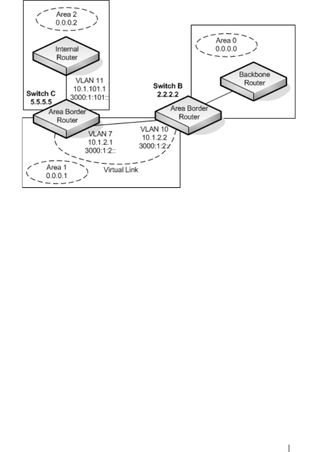
Configuring OSPF and OSPFv3 1185
Figure 35-37. OSPF Configuration—Virtual Link
Switch B is an ABR that directly connects Area 0 to Area 1. Note that in the
previous example, Switch B connected to a stub area and an NSSA. Virtual
links cannot be created across stub areas or NSSAs.
The following commands define a virtual link that traverses Area 1 to Switch
C (5.5.5.5).
To configure Switch B:
1
Configure the virtual link to Switch C for IPv4.
console#configure
console(config)#router ospf
console(config-router)#area 0.0.0.1 virtual-link 5.5.5.5
console(config-router)#exit
2
Configure the virtual link to Switch C for IPv6.
console#configure
console(config)#ipv6 router ospf
console(config-rtr)#area 0.0.0.1 virtual-link 5.5.5.5
console(config-rtr)#exit

1186 Configuring OSPF and OSPFv3
Switch C is a ABR that enables a virtual link from the remote Area 2 in the AS
to Area 0. The following commands define a virtual link that traverses Area 1
to Switch B (2.2.2.2).
To configure Switch C:
1
For IPv4, assign the router ID, create the virtual link to Switch B, and
associate the VLAN routing interfaces with the appropriate areas.
console(config)#router ospf
console(config-router)#area 0.0.0.1 virtual-link 2.2.2.2
console(config-router)#exit
2
For IPv6, assign the router ID and create the virtual link to Switch B.
console(config)#ipv6 router ospf
console(config-rtr)#area 0.0.0.1 virtual-link 2.2.2.2
console(config-rtr)#exit
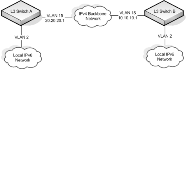
Configuring OSPF and OSPFv3 1187
Interconnecting an IPv4 Backbone and Local IPv6 Network
In Figure 35-38, two Dell Networking L3 switches are connected as shown in
the diagram. The VLAN 15 routing interface on both switches connects to an
IPv4 backbone network where OSPF is used as the dynamic routing protocol
to exchange IPv4 routes. OSPF allows device 1 and device 2 to learn routes to
each other (from the 20.20.20.x network to the 10.10.10.x network and vice
versa). The VLAN 2 routing interface on both devices connects to the local
IPv6 network. OSPFv3 is used to exchange IPv6 routes between the two
devices. The tunnel interface allows data to be transported between the two
remote IPv6 networks over the IPv4 network.
Figure 35-38. IPv4 and IPv6 Interconnection Example
To configure Switch A:
1
Create the VLANs.
console(config)#vlan 2,15
console(config-vlan70,80,90)#interface te1/0/1
console(config-if-Te1/0/1)#switchport mode trunk
console(config-if-Te1/0/1)#interface gi1/0/1
console(config-if-Gi1/0/1)#switchport access vlan 2
2
Enable IPv4 and IPv6 routing on the switch.
console(config)#ip routing
console(config)#ipv6 unicast-routing
3
Set the OSPF router ID.
console(config)#router ospf
console(config-router)#router-id 1.1.1.1
console(config-router)#exit

1188 Configuring OSPF and OSPFv3
4
Set the OSPFv3 router ID.
console(config)#ipv6 router ospf
console(config-rtr)#router-id 1.1.1.1
console(config-rtr)#exit
5
Configure the IPv4 address and OSPF area for VLAN 15.
console(config)#interface vlan 15
console(config-if-vlan15)#ip address 20.20.20.1 255.255.255.0
console(config-if-vlan15)#ip ospf area 0.0.0.0
console(config-if-vlan15)#exit
6
Configure the IPv6 address and OSPFv3 information for VLAN 2.
console(config)#interface vlan 2
console(config-if-vlan2)#ipv6 address 2020:1::1/64
console(config-if-vlan2)#ipv6 ospf
console(config-if-vlan2)#ipv6 ospf network point-to-point
console(config-if-vlan2)#exit
7
Configure the tunnel.
console(config)#interface tunnel 0
console(config-if-tunnel0)#ipv6 address 2001::1/64
console(config-if-tunnel0)#tunnel mode ipv6ip
console(config-if-tunnel0)#tunnel source 20.20.20.1
console(config-if-tunnel0)#tunnel destination 10.10.10.1
console(config-if-tunnel0)#ipv6 ospf
console(config-if-tunnel0)#ipv6 ospf network point-to-point
console(config-if-tunnel0)#exit
8
Configure the loopback interface. The switch uses the loopback IP address
as the OSPF and OSPFv3 router ID.
console(config)#interface loopback 0
console(config-if-loopback0)#ip address 1.1.1.1 255.255.255.0
console(config-if-loopback0)#exit
console(config)#exit

Configuring OSPF and OSPFv3 1189
To configure Switch B:
1
Create the VLANs.
console(config)#vlan 2,15
console(config-vlan70,80,90)#interface te1/0/1
console(config-if-Te1/0/1)#switchport mode trunk
console(config-if-Te1/0/1)#interface gi1/0/1
console(config-if-Gi1/0/1)#switchport access vlan 2
2
Enable IPv4 and IPv6 routing on the switch.
console(config)#ip routing
console(config)#ipv6 unicast-routing
3
Set the OSPF router ID.
console(config)#router ospf
console(config-router)#router-id 2.2.2.2
console(config-router)#exit
4
Set the OSPFv3 router ID.
console(config)#ipv6 router ospf
console(config-rtr)#router-id 2.2.2.2
console(config-rtr)#exit
5
Configure the IPv4 address and OSPF area for VLAN 15.
console(config)#interface vlan 15
console(config-if-vlan15)#ip address 10.10.10.1 255.255.255.0
console(config-if-vlan15)#ip ospf area 0.0.0.0
console(config-if-vlan15)#exit
6
Configure the IPv6 address and OSPFv3 information for VLAN 2.
console(config)#interface vlan 2
console(config-if-vlan2)#ipv6 address 2020:2::2/64
console(config-if-vlan2)#ipv6 ospf
console(config-if-vlan2)#ipv6 ospf network point-to-point
console(config-if-vlan2)#exit
7
Configure the tunnel.
console(config)#interface tunnel 0
console(config-if-tunnel0)#ipv6 address 2001::2/64
console(config-if-tunnel0)#tunnel mode ipv6ip
console(config-if-tunnel0)#tunnel source 10.10.10.1
console(config-if-tunnel0)#tunnel destination 20.20.20.1
console(config-if-tunnel0)#ipv6 ospf
console(config-if-tunnel0)#ipv6 ospf network point-to-point
console(config-if-tunnel0)#exit
1190 Configuring OSPF and OSPFv3
8
Configure the loopback interface. The switch uses the loopback IP address
as the OSPF and OSPFv3 router ID.
console(config)#interface loopback 0
console(config-if-loopback0)#ip address 2.2.2.2 255.255.255.0
console(config-if-loopback0)#exit
console(config)#exit
Configuring the Static Area Range Cost
Figure 35-39 shows a topology for the configuration that follows.
Figure 35-39. Static Area Range Cost Example Topology
1
Configure R0.
terminal length 0
config
hostname ABR-R0
line console
exec-timeout 0
exit
vlan 101-103
exit
ip routing
router ospf
router-id 10.10.10.10
R3
ABR
R0
VLAN 103
Area 0
R1 R2
Area 1
VLAN 104
VLAN 101 VLAN 102

Configuring OSPF and OSPFv3 1191
network 172.20.0.0 0.0.255.255 area 0
network 172.21.0.0 0.0.255.255 area 1
area 1 range 172.21.0.0 255.255.0.0 summarylink
timers spf 3 5
exit
interface vlan 101
ip address 172.21.1.10 255.255.255.0
ip ospf hello-interval 1
ip ospf dead-interval 4
ip ospf network point-to-point
exit
interface te1/0/21
switchport mode trunk
description “R1”
exit
interface vlan 102
ip address 172.21.2.10 255.255.255.0
ip ospf hello-interval 1
ip ospf dead-interval 4
ip ospf network point-to-point
exit
interface te1/0/22
description “R2”
switchport mode trunk
exit
interface vlan 103
ip address 172.20.1.10 255.255.255.0
ip ospf hello-interval 1
ip ospf dead-interval 4
ip ospf network point-to-point
exit
interface te1/0/23
switchport mode trunk
description “R3”
exit
exit
2
Configure R1.
terminal length 0
config
hostname R1
line console
exec-timeout 0
exit
vlan 101,104
exit

1192 Configuring OSPF and OSPFv3
ip routing
router ospf
router-id 1.1.1.1
network 172.21.0.0 0.0.255.255 area 1
timers spf 3 5
exit
interface vlan 101
ip address 172.21.1.1 255.255.255.0
routing
ip ospf hello-interval 1
ip ospf dead-interval 4
ip ospf network point-to-point
exit
interface te1/0/21
switchport mode trunk
exit
interface vlan 104
ip address 172.21.3.1 255.255.255.0
routing
ip ospf hello-interval 1
ip ospf dead-interval 4
ip ospf network point-to-point
exit
interface te1/0/22
switchport mode trunk
exit
interface loopback 0
ip address 172.21.254.1 255.255.255.255
exit
exit
3
Configure R2.
terminal length 0
config
line console
serial timeout 0
exit
ip routing
router ospf
router-id 2.2.2.2
network 172.21.0.0 0.0.255.255 area 1
timers spf 3 5
exit
vlan 102,104
exit
interface vlan 102

Configuring OSPF and OSPFv3 1193
ip address 172.21.2.2 255.255.255.0
routing
ip ospf hello-interval 1
ip ospf dead-interval 4
ip ospf network point-to-point
exit
interface te1/0/21
switchport mode trunk
exit
interface vlan 104
ip address 172.21.3.2 255.255.255.0
routing
ip ospf hello-interval 1
ip ospf dead-interval 4
ip ospf network point-to-point
exit
interface te1/0/22
switchport mode trunk
exit
interface loopback 0
ip address 172.21.254.2 255.255.255.255
exit
exit
4
R3 config:
terminal length 0
config
line console
serial timeout 0
exit
ip routing
router ospf
router-id 3.3.3.3
network 172.21.0.0 0.0.255.255 area 0
timers spf 3 5
exit
vlan 103
exit
interface vlan 103
ip address 172.21.1.1 255.255.255.0
routing
ip ospf hello-interval 1
ip ospf dead-interval 4
ip ospf network point-to-point
exit
interface te1/0/21

1194 Configuring OSPF and OSPFv3
switchport mode trunk
exit
interface loopback 0
ip address 172.21.254.2 255.255.255.255
exit
exit
Discussion
With no area range cost specified, the range uses auto cost:
(ABR-R0) #show ip ospf range 1
Prefix Subnet Mask Type Action Cost Active
172.21.0.0 255.255.0.0 S Advertise Auto Y
(ABR-R0) #show ip ospf database summary
Network Summary States (Area 0.0.0.0)
LS Age: 644
LS options: (E-Bit)
LS Type: Network Summary LSA
LS Id: 172.21.0.0 (network prefix)
Advertising Router: 10.10.10.10
LS Seq Number: 0x80000002
Checksum: 0x8ee1
Length: 28
Network Mask: 255.255.0.0
Metric: 2
Min—The cost can be set to 0, the minimum value. OSPF re-advertises the
summary LSA with a metric of 0:
(ABR-R0) (config-router)#area 1 range 172.21.0.0 255.255.0.0 summarylink advertise cost ?
<0-16777215> Set area range cost
(ABR-R0) (config-router)#area 1 range 172.21.0.0 255.255.0.0 summarylink
advertise cost 0
(ABR-R0) #show ip ospf range 1
Prefix Subnet Mask Type Action Cost Active
172.21.0.0 255.255.0.0 S Advertise 0 Y
(ABR-R0) #show ip ospf 0 database summary
Network Summary States (Area 0.0.0.0)
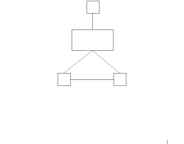
Configuring OSPF and OSPFv3 1195
LS Age: 49
LS options: (E-Bit)
LS Type: Network Summary LSA
LS Id: 172.21.0.0 (network prefix)
Advertising Router: 10.10.10.10
LS Seq Number: 0x80000003
Checksum: 0x78f8
Length: 28
Network Mask: 255.255.0.0
Metric: 0
The cost can be set to the maximum value, 16,777,215, which is LSInfinity.
Since OSPF cannot send a type 3 summary LSA with this metric (according
to RFC 2328), the summary LSA is flushed. The individual routes are not re-
advertised.
Configuring Flood Blocking
Figure 35-40 shows an example topology for flood blocking. The
configuration follows.
Figure 35-40. Flood Blocking Topology
1
Configure R0:
terminal length 0
config
hostname R0
line console
R3
R0
VLAN 103
R1 R2
VLAN 104
VLAN 101 VLAN 102

1196 Configuring OSPF and OSPFv3
exec-timeout 0
exit
vlan 101-103
exit
ip routing
router ospf
router-id 10.10.10.10
network 172.20.0.0 0.0.255.255 area 0
network 172.21.0.0 0.0.255.255 area 0
timers spf 3 5
exit
interface vlan 101
ip address 172.21.1.10 255.255.255.0
ip ospf hello-interval 1
ip ospf dead-interval 4
ip ospf network point-to-point
exit
interface te1/0/21
switchport mode trunk
description “R1”
exit
interface vlan 102
ip address 172.21.2.10 255.255.255.0
ip ospf hello-interval 1
ip ospf dead-interval 4
ip ospf network point-to-point
exit
interface te1/0/22
description “R2”
switchport mode trunk
exit
interface vlan 103
ip address 172.20.1.10 255.255.255.0
ip ospf hello-interval 1
ip ospf dead-interval 4
ip ospf network point-to-point
exit
interface te1/0/23
switchport mode trunk
description “R3”
exit
exit
2
Configure R1:
terminal length 0

Configuring OSPF and OSPFv3 1197
config
hostname R1
line console
exec-timeout 0
exit
vlan 101,104
exit
ip routing
router ospf
router-id 1.1.1.1
network 172.21.0.0 0.0.255.255 area 0
timers spf 3 5
exit
interface vlan 101
ip address 172.21.1.1 255.255.255.0
routing
ip ospf hello-interval 1
ip ospf dead-interval 4
ip ospf network point-to-point
exit
interface te1/0/21
switchport mode trunk
exit
interface vlan 104
ip address 172.21.3.1 255.255.255.0
routing
ip ospf hello-interval 1
ip ospf dead-interval 4
ip ospf network point-to-point
exit
interface te1/0/22
switchport mode trunk
exit
interface loopback 0
ip address 172.21.254.1 255.255.255.255
exit
exit
3
Configure R2:
terminal length 0
config
line console
serial timeout 0
exit
ip routing

1198 Configuring OSPF and OSPFv3
router ospf
router-id 2.2.2.2
network 172.21.0.0 0.0.255.255 area 0
timers spf 3 5
exit
vlan 102,104
exit
interface vlan 102
ip address 172.21.2.2 255.255.255.0
routing
ip ospf hello-interval 1
ip ospf dead-interval 4
ip ospf network point-to-point
exit
interface te1/0/21
switchport mode trunk
exit
interface vlan 104
ip address 172.21.3.2 255.255.255.0
routing
ip ospf hello-interval 1
ip ospf dead-interval 4
ip ospf network point-to-point
exit
interface te1/0/22
switchport mode trunk
exit
interface loopback 0
ip address 172.21.254.2 255.255.255.255
exit
exit
4
Configure R3:
terminal length 0
config
line console
serial timeout 0
exit
ip routing
router ospf
router-id 3.3.3.3
network 172.21.0.0 0.0.255.255 area 0
timers spf 3 5
exit
vlan 103

Configuring OSPF and OSPFv3 1199
exit
interface vlan 103
ip address 172.21.1.1 255.255.255.0
routing
ip ospf hello-interval 1
ip ospf dead-interval 4
ip ospf network point-to-point
exit
interface te1/0/21
switchport mode trunk
exit
interface loopback 0
ip address 172.21.254.2 255.255.255.255
exit
exit
Discussion
With flood blocking disabled on all interfaces, sending a T3 summary LSA
from R3 to R0 will cause R0 to forward the LSA on its interface to R1.
Enabling flood blocking on R0's interface to R1 will inhibit this behavior.
(R0)(config-if-vlan101)ip ospf database-filter all out
A trace on the R3-R0 link shows that the LSA is actually flooded from R1 to
R0, since R1 received the LSA via R2. Even though R1 does not receive this
LSA directly from R0, it still correctly computes the route through the R0:
(R1) #show ip route
console#show ip route
Route Codes: R - RIP Derived, O - OSPF Derived, C - Connected, S - Static
B - BGP Derived, E - Externaly Derived, IA - OSPF Inter Area
E1 - OSPF External Type 1, E2 - OSPF External Type 2
N1 - OSPF NSSA External Type 1, N2 - OSPF NSSA External Type 2
O IA 100.0.0.0/24 [110/2] via 172.21.1.10, 00h:01m:35s, 0/25
OSPF also blocks external LSAs on the blocked interface. Stopping and
restarting R3's OSPF protocol causes R3 to re-originate its router LSA. R0
does not send R3's router LSA on the blocked interface.
With flood blocking enabled on the R0 interface, if the link from R0 to R1
bounces, R0 Database Description packets do not include any LSAs.
However, database synchronization still occurs (through R2) and R1
computes the correct routes after the link is restored.

1200 Configuring OSPF and OSPFv3

Configuring RIP 1201
36
Configuring RIP
This chapter describes how to configure Routing Information Protocol (RIP)
on the switch. RIP is a dynamic routing protocol for IPv4 networks.
The topics covered in this chapter include:
• RIP Overview
• Default RIP Values
• Configuring RIP Features (Web)
• Configuring RIP Features (CLI)
• RIP Configuration Example
RIP Overview
RIP is an Interior Gateway Protocol (IGP) that performs dynamic routing
within a network. Dell Networking series switches support two dynamic
routing protocols: OSPF and Routing Information Protocol (RIP).
Unlike OSPF, RIP is a distance-vector protocol and uses UDP broadcasts to
maintain topology information and hop counts to determine the best route to
transmit IP traffic. RIP is best suited for small, homogenous networks.
How Does RIP Determine Route Information?
The routing information is propagated in RIP update packets that are sent
out both periodically and in the event of a network topology change. On
receipt of a RIP update, depending on whether the specified route exists or
does not exist in the route table, the router may modify, delete or add the
route to its route table.
RIP uses hop count, which is the number of routers an IP packet must pass
through, to calculate the best route for a packet. A route with a low hop count
is preferred over a route with a higher hop count. A directly-connected route
has a hop-count of 0. With RIP, the maximum number of hops from source to
destination is 15. Packets with a hop count greater than 15 are dropped
because the destination network is considered unreachable.

1202 Configuring RIP
What Is Split Horizon?
RIP uses a technique called split horizon to avoid problems caused by
including routes in updates sent to the router from which the route was
originally learned. With simple split horizon, a route is not included in
updates sent on the interface on which it was learned. In split horizon with
poison reverse, a route is included in updates sent on the interface where it
was learned, but the metric is set to infinity.
What RIP Versions Are Supported?
There are two versions of RIP:
• RIP-1 defined in RFC 1058
– Routes are specified by IP destination network and hop count
– The routing table is broadcast to all stations on the attached network
• RIP-2 defined in RFC 1723
– Route specification is extended to include subnet mask and gateway
– The routing table is sent to a multicast address, reducing network
traffic
– An authentication method is used for security
The Dell Networking series switches support both versions of RIP. You may
configure a given port:
• To receive packets in either or both formats
• To transmit packets formatted for RIP-1 or RIP-2 or to send RIP-2 packets
to the RIP-1 broadcast address
• To prevent any RIP packets from being received
• To prevent any RIP packets from being transmitted

Configuring RIP 1203
Default RIP Values
RIP is globally enabled by default. To make it operational on the router, you
configure and enable RIP for particular VLAN routing interfaces.
Table 36-1 shows the global default values for RIP.
Table 36-2 shows the per-interface default values for RIP.
Table 36-1. RIP Global Defaults
Parameter Default Value
Admin Mode Enabled
Split Horizon Mode Simple
Auto Summary Mode Disabled
Host Routes Accept Mode Enabled
Default Information Originate Disabled
Default Metric None configured
Route Redistribution Disabled for all sources.
Table 36-2. RIP Per-Interface Defaults
Parameter Default Value
Admin Mode Disabled
Send Version RIPv2
Receive Version Both
Authentication Type None
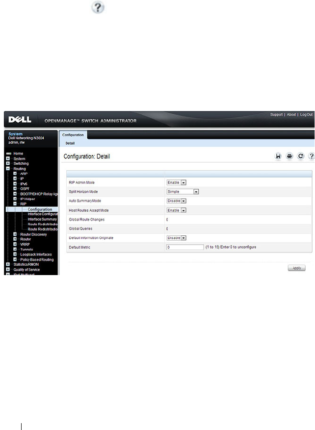
1204 Configuring RIP
Configuring RIP Features (Web)
This section provides information about the OpenManage Switch
Administrator pages for configuring and monitoring RIP features on a Dell
Networking N2000, N3000, and N4000 series switches. For details about the
fields on a page, click at the top of the page.
RIP Configuration
Use the Configuration
page to enable and configure or disable RIP in Global
mode. To display the page, click Routing
→
RIP
→
Configuration in the
navigation panel.
Figure 36-1. RIP Configuration
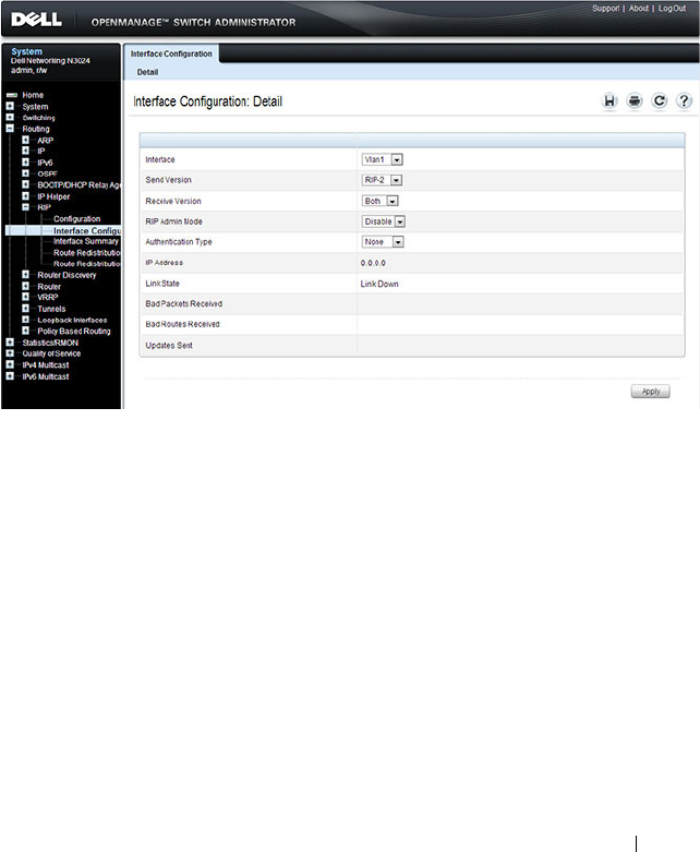
Configuring RIP 1205
RIP Interface Configuration
Use the Interface Configuration
page to enable and configure or to disable
RIP on a specific interface.
To display the page, click Routing
→
RIP
→
Interface Configuration in the
navigation panel.
Figure 36-2. RIP Interface Configuration
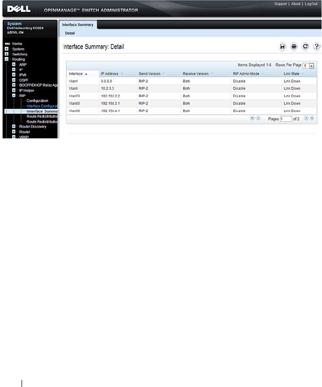
1206 Configuring RIP
RIP Interface Summary
Use the Interface Summary
page to display RIP configuration status on an
interface.
To display the page, click Routing
→
RIP
→
Interface Summary in the
navigation panel.
Figure 36-3. RIP Interface Summary
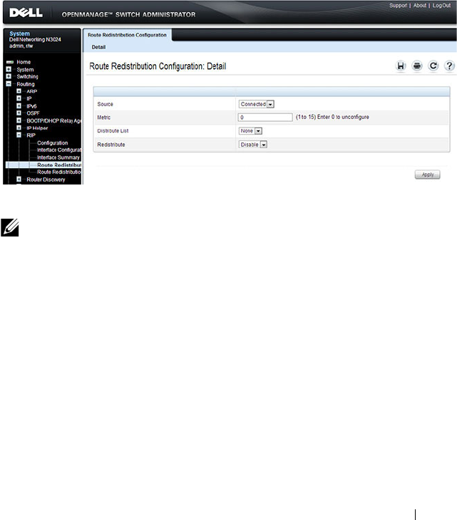
Configuring RIP 1207
RIP Route Redistribution Configuration
Use the Route Redistribution Configuration
page to configure the RIP
Route Redistribution parameters. The allowable values for each fields are
displayed next to the field. If any invalid values are entered, an alert message
is displayed with the list of all the valid values.
To display the page, click Routing
→
RIP
→
Route Redistribution
Configuration in the navigation panel.
Figure 36-4. RIP Route Redistribution Configuration
NOTE: Static reject routes are not redistributed by RIP. For a static reject route,
the next hop interface value is Null0. Packets to the network address specified in
static reject routes are intentionally dropped.
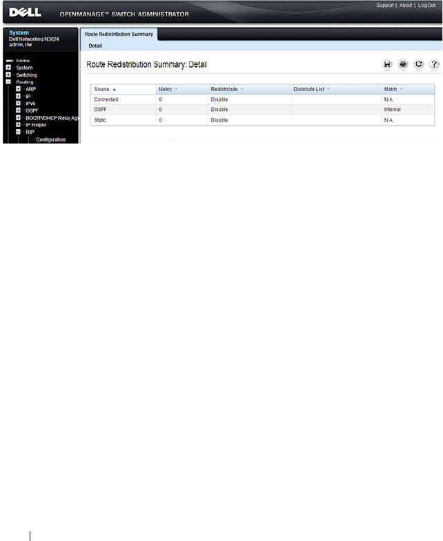
1208 Configuring RIP
RIP Route Redistribution Summary
Use the Route Redistribution Summary
page to display Route Redistribution
configurations.
To display the page, click Routing
→
RIP
→
Route Redistribution Summary
in the navigation panel.
Figure 36-5. RIP Route Redistribution Summary

Configuring RIP 1209
Configuring RIP Features (CLI)
This section provides information about the commands you use to configure
RIP settings on the switch. For more information about the commands, see
the
Dell Networking N2000, N3000, and N4000 Series Switches CLI
Reference Guide
at support.dell.com/manuals.
Configuring Global RIP Settings
Beginning in Privileged EXEC mode, use the following commands to
configure various global RIP settings for the switch.
NOTE: RIP is enabled by default. The Global RIP Settings are optional.
Command Purpose
configure Enter global configuration mode.
router rip Enter OSPF configuration mode.
split-horizon {none |
simple | poison}
Set the RIP split horizon mode.
•
none
— RIP does not use split horizon to avoid routing
loops.
•
simple
— RIP uses split horizon to avoid routing loops.
•
poison
— RIP uses split horizon with poison reverse
(increases routing packet update size).
auto-summary Enable the RIP auto-summarization mode.
no hostroutesaccept Prevent the switch from accepting host routes.
default-information
originate
Control the advertisement of default routes.
default-metric
metric-
value
Set a default for the metric of distributed routes.
The
metric-value
variable is the metric (or preference) value
of the default route. (Range: 1–15)
enable Reset the default administrative mode of RIP in the router
(active)
CTRL + Z Exit to Privileged EXEC mode.
show ip rip View various RIP settings for the switch.

1210 Configuring RIP
Configuring RIP Interface Settings
Beginning in Privileged EXEC mode, use the following commands to
configure per-interface RIP settings.
Command Purpose
configure Enter global configuration mode.
interface vlan
vlan-id
Enter Interface Configuration mode for the specified
VLAN.
ip rip Enable RIP on the interface.
ip rip send version {rip1
rip1c | rip2 |none}
Configure the interface to allow RIP control packets of the
specified version(s) to be sent.
ip rip receive version
{rip1 | rip2 | both |
none}
Configure the interface to allow RIP control packets of the
specified version(s) to be received.
ip rip authentication
{none | {simple
key
} |
{encrypt
key key-id
}
set the RIP Version 2 Authentication Type and Key for the
interface.
•
key
— Authentication key for the specified interface.
(Range: 16 bytes or less)
•
encrypt
— Specifies the Ethernet unit/port of the
interface to view information.
•
key-id
— Authentication key identifier for
authentication type encrypt. (Range: 0-255)
exit Exit to Global Configuration Mode
exit Exit to Privileged Exec mode.
show ip rip interface vlan
vlan-id
View RIP configuration information for the specified
routing interface.
show ip rip interface
brief
View summary information about the RIP configuration
on all interfaces.

Configuring RIP 1211
Configuring Route Redistribution Settings
Beginning in Privileged EXEC mode, use the following commands to
configure an OSPF area range and to configure route redistribution settings.
Command Purpose
configure Enter global configuration mode.
router rip Enter RIP configuration mode.
distribute-list
accesslistname
out {ospf |
static | connected}
Specify the access list to filter routes received from the
source protocol. The ACL must already exist on the
switch. For information about the commands you use to
configure ACLs, see "Configuring ACLs (CLI)" on
page 612.
•
accesslistname
— The name used to identify an existing
ACL.
•
ospf
— Apply the specified access list when OSPF is the
source protocol.
•
static
— Apply the specified access list when packets
come through the static route.
•
connected
— Apply the specified access list when
packets come from a directly connected route.
redistribute {static |
connected} [metric
integer
]
Configure RIP to allow redistribution of routes from the
specified source protocol/routers.
•
static
— Specifies that the source is a static route.
•
connected
— Specifies that the source is a directly
connected route.
•
metric
— Specifies the metric to use when
redistributing the route. Range: 1-15.

1212 Configuring RIP
redistribute ospf [metric
metric
] [match [internal]
[external 1] [external 2]
[nssa-external 1] [nssa-
external 2]]
Configure RIP to allow redistribution of routes from the
OSPF.
•
ospf
— Specifies OSPF as the source protocol.
•
metric
— Specifies the metric to use when
redistributing the route. Range: 1-15.
•
internal
— Adds internal matches to any match types
presently being redistributed.
•
external 1
— Adds routes imported into OSPF as Type-
1 external routes into any match types presently being
redistributed.
•
external 2
— Adds routes imported into OSPF as Type-
2 external routes into any match types presently being
redistributed.
•
nssa-external 1
— Adds routes imported into OSPF as
NSSA Type-1 external routes into any match types
presently being redistributed.
•
nssa-external 2
— Adds routes imported into OSPF as
NSSA Type-2 external routes into any match types
presently being redistributed.
distance rip
integer
Set the route preference value of RIP in the router. Lower
route preference values are preferred when determining
the best route.
exit Exit to Global Config mode.
exit Exit to Privileged Exec mode.
show ip rip View information about the RIP route distribution
configuration.
Command Purpose
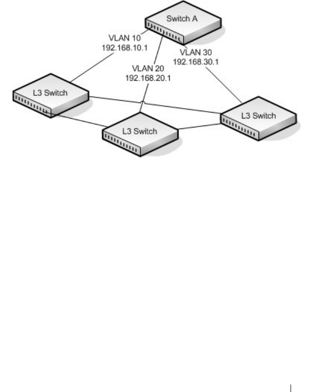
Configuring RIP 1213
RIP Configuration Example
This example includes four Dell Networking switches that use RIP to
determine network topology and route information. The commands in this
example configure Switch A shown in Figure 36-6.
Figure 36-6. RIP Network Diagram
To configure the switch:
1
Enable routing on the switch
console#config
console(config)#ip routing
2
Create VLANs 10, 20, and 30.
console(config)#vlan 10,20,30
console(config-vlan10,20,30)#interface gi1/0/1
console(config-if-Gi1/0/1)#switchport access vlan 10
console(config-if-Gi1/0/1)#interface gi1/0/2
console(config-if-Gi1/0/2)#switchport access vlan 20
console(config-if-Gi1/0/2)#interface gi1/0/3
console(config-if-Gi1/0/3)#switchport access vlan 30
3
Assign an IP address and enable RIP on each interface. Additionally, the
commands specify that each interface can receive both RIP-1 and RIP-2
frames but send only RIP-2 formatted frames.
console(config)#interface vlan 10

1214 Configuring RIP
console(config-if-vlan10)#ip address 192.168.10.1 255.255.255.0
console(config-if-vlan10)#ip rip
console(config-if-vlan10)#ip rip receive version both
console(config-if-vlan10)#ip rip send version rip2
console(config-if-vlan10)#exit
console(config)#interface vlan 20
console(config-if-vlan20)#ip address 192.168.20.1 255.255.255.0
console(config-if-vlan20)#ip rip
console(config-if-vlan20)#ip rip receive version both
console(config-if-vlan20)#ip rip send version rip2
console(config-if-vlan20)#exit
console(config)#interface vlan 30
console(config-if-vlan30)#ip address 192.168.30.1 255.255.255.0
console(config-if-vlan30)#ip rip
console(config-if-vlan30)#ip rip receive version both
console(config-if-vlan30)#ip rip send version rip2
console(config-if-vlan30)#exit
4
Enable auto summarization of subprefixes when crossing classful
boundaries.
console(config)#router rip
console(config-router)#auto-summary
console(config-router)#exit
console(config)#exit
5
Verify the configuration
console#show ip rip
RIP Admin Mode.......................... Enable
Split Horizon Mode...................... Simple
Auto Summary Mode....................... Enable
Host Routes Accept Mode................. Enable
Global route changes.................... 0
Global queries.......................... 0
Default Metric.................... Not configured
Default Route Advertise........... 0
console#show ip rip interface brief
Interface IP Address Send
Version
Receive
Version
RIP
Mode
Link
State
---------- ------------ --------- ------- -------- ------
Vl1 0.0.0.0 RIP-2 RIP-2 Disable Down

Configuring RIP 1215
Vl10 192.168.10.1 RIP-2 Both Enable Down
Vl20 192.168.10.1 RIP-2 Both Enable Down
Vl30 192.168.10.1 RIP-2 Both Disable Down

1216 Configuring RIP

Configuring VRRP 1217
37
Configuring VRRP
This chapter describes how to configure Virtual Routing Redundancy
Protocol (VRRP) on the switch. VRRP can help create redundancy on
networks in which end-stations are statically configured with the default
gateway IP address.
The topics covered in this chapter include:
• VRRP Overview
• Default VRRP Values
• Configuring VRRP Features (Web)
• Configuring VRRP Features (CLI)
• VRRP Configuration Example
VRRP Overview
The Virtual Router Redundancy (VRRP) protocol is designed to handle
default router (L3 switch) failures by providing a scheme to dynamically elect
a backup router. VRRP can help minimize black hole periods due to the
failure of the default gateway router during which all traffic directed towards
it is lost until the failure is detected.
How Does VRRP Work?
VRRP eliminates the single point of failure associated with static default
routes by enabling a backup router to take over from a master router without
affecting the end stations using the route. The end stations will use a virtual
IP address that will be recognized by the backup router if the master router
fails. Participating routers use an election protocol to determine which router
is the master router at any given time. A maximum of 50 virtual routers may
NOTE: This feature is not available on N2000 switches.

1218 Configuring VRRP
be configured. A given port may appear as more than one virtual router to the
network, also, more than one port on a switch may be configured as a virtual
router.
With VRRP, a virtual router is associated with one or more IP addresses that
serve as default gateways. In the event that the VRRP router controlling these
IP addresses (formally known as the master) fails, the group of IP addresses
and the default forwarding role is taken over by a Backup VRRP router.
What Is the VRRP Router Priority?
The VRRP router priority is a value from 1–255 that determines which router
is the master. The greater the number, the higher the priority. If the virtual IP
address is the IP address of a VLAN routing interface on one of the routers in
the VRRP group, the router with IP address that is the same as the virtual IP
address is the interface owner and automatically has a priority of 255. By
default, this router is the VRRP master in the group.
If no router in the group owns the VRRP virtual IP address, the router with
the highest configured priority is the VRRP master. If multiple routers have
the same priority, the router with the highest IP address becomes the VRRP
master.
If the VRRP master fails, other members of the VRRP group will elect a
master based on the configured router priority values. For example, router A is
the interface owner and master, and it has a priority of 255. Router B is
configured with a priority of 200, and Router C is configured with a priority of
190. If Router A fails, Router B assumes the role of VRRP master because it
has a higher priority.
What Is VRRP Preemption?
If preempt mode is enabled and a router with a higher priority joins the VRRP
group, it takes over the VRRP master role if the current VRRP master is not
the owner of the virtual IP address. The preemption delay controls how long
to wait to determine whether a higher priority Backup router preempts a
lower priority master. In certain cases, for example, during periods of network
congestion, a backup router might fail to receive advertisements from the
master. This could cause members in the VRRP group to change their states
frequently, i.e. flap. The problem can be resolved by setting the VRRP
preemption delay timer to a non-zero value.

Configuring VRRP 1219
What Is VRRP Accept Mode?
The accept mode allows the switch to respond to pings (ICMP Echo
Requests) sent to the VRRP virtual IP address. The VRRP specification (RFC
3768) indicates that a router may accept IP packets sent to the virtual router
IP address only if the router is the address owner. In practice, this restriction
makes it more difficult to troubleshoot network connectivity problems. When
a host cannot communicate, it is common to ping the host's default gateway
to determine whether the problem is in the first hop of the path to the
destination. When the default gateway is a virtual router that does not
respond to pings, this troubleshooting technique is unavailable. In the Dell
Networking switch VRRP feature, you can enable Accept Mode to allow the
system to respond to pings that are sent to the virtual IP address.
This capability adds support for responding to pings, but does not allow the
VRRP master to accept other types of packets. The VRRP master responds to
both fragmented and un-fragmented ICMP Echo Request packets. The
VRRP master responds to Echo Requests sent to the virtual router's primary
address or any of its secondary addresses.
Members of the virtual router who are in backup state discard ping packets
destined to VRRP addresses, just as they discard any Ethernet frame sent to a
VRRP MAC address.
When the VRRP master responds with an Echo Reply, the source IPv4
address is the VRRP address and source MAC address is the virtual router's
MAC address.
What Are VRRP Route and Interface Tracking?
The VRRP Route/Interface Tracking feature extends VRRP capability to allow
tracking of specific routes and interface IP states within the router that can
alter the priority level of a virtual router for a VRRP group.
VRRP interface tracking monitors a specific interface IP state within the
router. Depending on the state of the tracked interface, the feature can alter
the VRRP priority level of a virtual router for a VRRP group.
NOTE: An exception to the priority level change is that if the VRRP group is the IP
address owner, its priority is fixed at 255 and cannot be reduced through the
tracking process.

1220 Configuring VRRP
With standard VRRP, the backup router takes over only if the router goes
down. With VRRP interface tracking, if a tracked interface goes down on the
VRRP master, the priority decrement value is subtracted from the router
priority. If the master router priority becomes less than the priority on the
backup router, the backup router takes over. If the tracked interface becomes
up, the value of the priority decrement is added to the current router priority.
If the resulting priority is more than the backup router priority, the original
VRRP master resumes control.
VRRP route tracking monitors the reachability of an IP route. A tracked route
is considered up when a routing table entry exists for the route and the route
is accessible. When the tracked route is removed from the routing table, the
priority of the VRRP router will be reduced by the priority decrement value.
When the tracked route is added to the routing table, the priority will be
incremented by the same.

Configuring VRRP 1221
Default VRRP Values
Table 37-1 shows the global default values for VRRP.
Table 37-1. VRRP Defaults
Parameter Default Value
Admin Mode Disabled
Virtual Router ID (VRID) None (Range 1-255)
Preempt Mode Enabled
Preempt Delay 0 Seconds
Learn Advertisement Timer Interval Enabled
Accept Mode Disabled
Priority 100
Advertisement Interval 1
Authentication None
Route Tracking No routes tracked
Interface Tracking No interfaces tracked
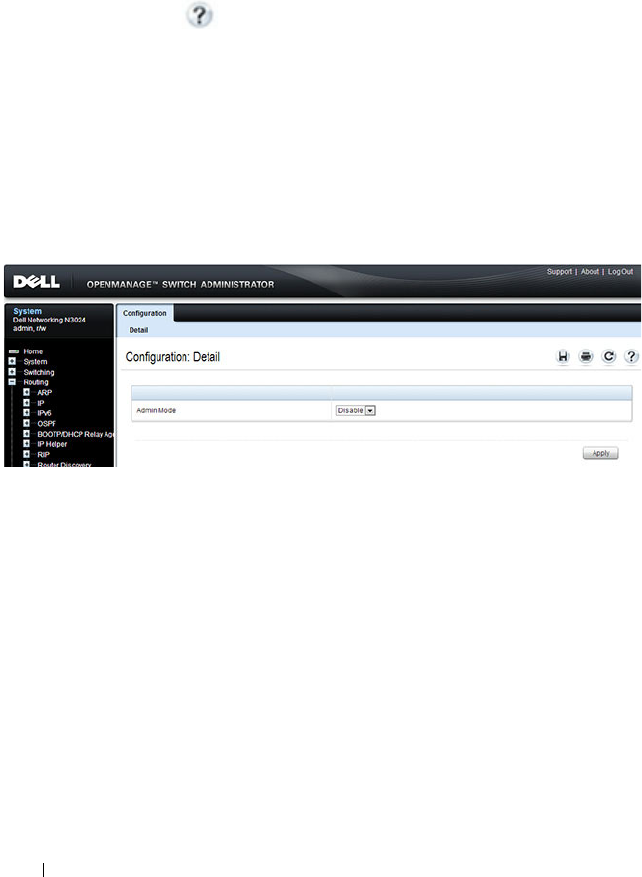
1222 Configuring VRRP
Configuring VRRP Features (Web)
This section provides information about the OpenManage Switch
Administrator pages for configuring and monitoring VRRP features on a Dell
Networking N2000, N3000, and N4000 series switches. For details about the
fields on a page, click at the top of the page.
VRRP Configuration
Use the Configuration
page to enable or disable the administrative status of a
virtual router.
To display the page, click Routing
→
VRRP
→
Configuration in the
navigation panel.
Figure 37-1. VRRP Configuration
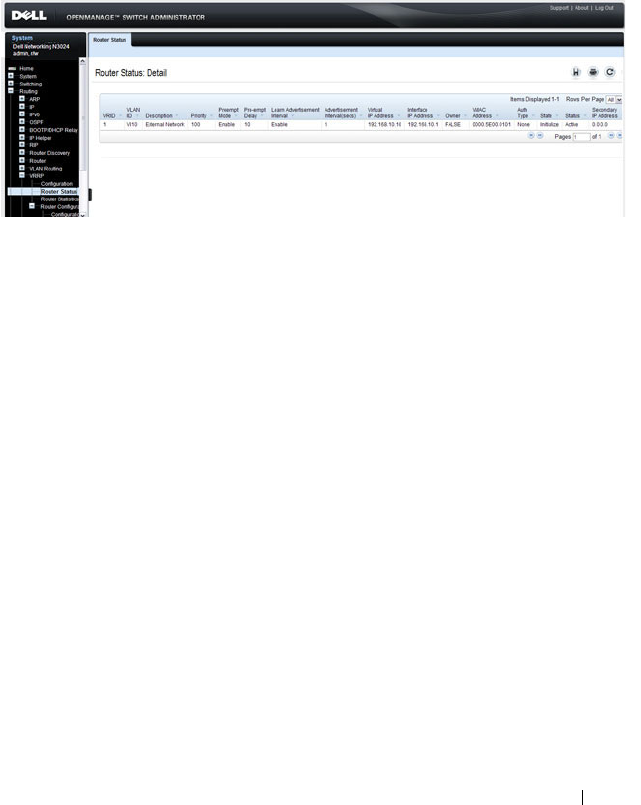
Configuring VRRP 1223
VRRP Virtual Router Status
Use the Router Status
page to display virtual router status.
To display the page, click Routing
→
VRRP
→
Router Status in the
navigation panel.
Figure 37-2. Virtual Router Status
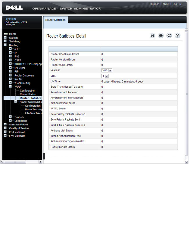
1224 Configuring VRRP
VRRP Virtual Router Statistics
Use the Router Statistics
page to display statistics for a specified virtual
router.
To display the page, click Routing
→
VRRP
→
Router Statistics in the
navigation panel.
Figure 37-3. Virtual Router Statistics
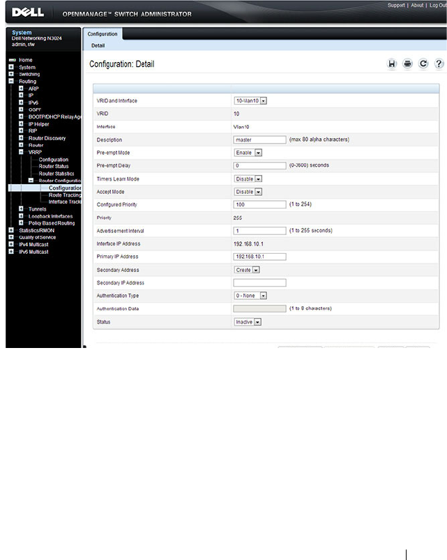
Configuring VRRP 1225
VRRP Router Configuration
Use the Configuration
page to configure a virtual router.
To display the page, click Routing
→
VRRP
→
Router Configuration
→
Configuration in the navigation panel.
Figure 37-4. VRRP Router Configuration
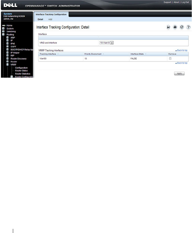
1226 Configuring VRRP
VRRP Route Tracking Configuration
Use the Route Tracking
Configuration page to view routes that are tracked
by VRRP and to add new tracked routes.
To display the page, click Routing
→
VRRP
→
Router Configuration
→
Route Tracking Configuration in the navigation panel.
Figure 37-5. VRRP Route Tracking Configuration
Configuring VRRP Route Tracking
To configure VRRP route tracking:
1
From the
Route Tracking
Configuration
page, click
Add
.
The
Add Route Tracking
page displays.
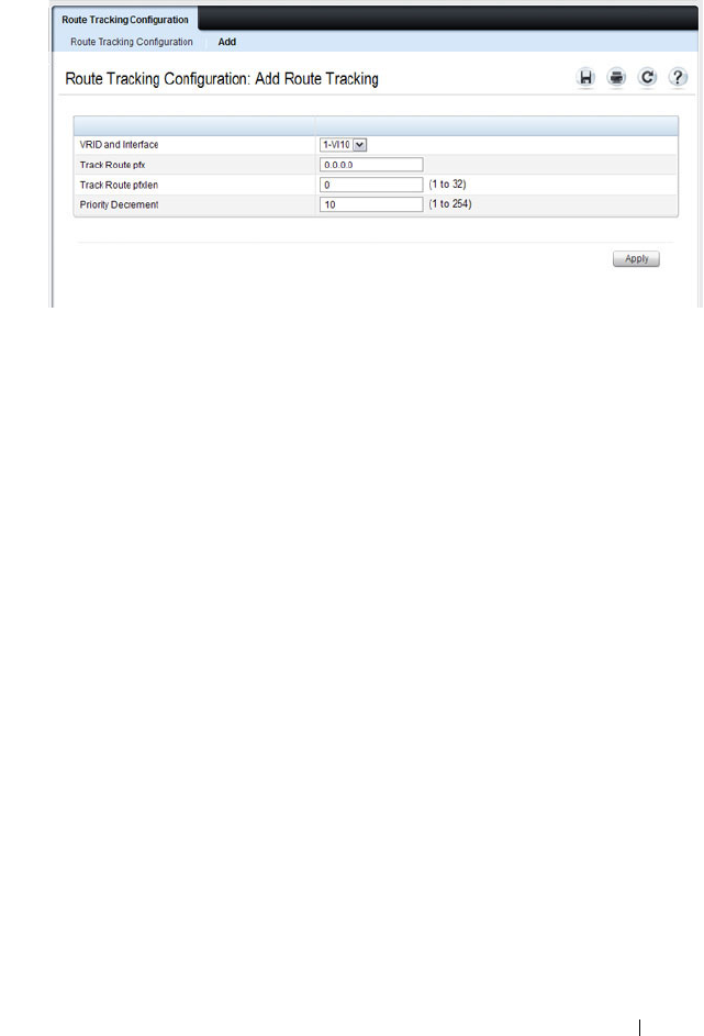
Configuring VRRP 1227
Figure 37-6. Add Route Tracking
2
Select the virtual router ID and VLAN routing interface that will track the
route.
3
Specify the destination network address (track route prefix) for the route
to track. Use dotted decimal format, for example 192.168.10.0.
4
Specify the prefix length for the tracked route.
5
Specify a value for the
Priority Decrement
to define the amount that the
router priority will be decreased when a tracked route becomes
unreachable.
6.
Click
Apply
to update the switch.
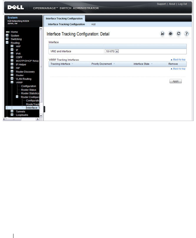
1228 Configuring VRRP
VRRP Interface Tracking Configuration
Use the Interface Tracking Configuration page to view interfaces that are
tracked by VRRP and to add new tracked interfaces.
To display the page, click Routing
→
VRRP
→
Router Configuration
→
Interface Tracking Configuration in the navigation panel.
Figure 37-7. VRRP Interface Tracking Configuration
Configuring VRRP Interface Tracking
To configure VRRP interface tracking:
1
From the
Interface Tracking Configuration
page, click
Add
.
The
Add
Interface
Tracking
page displays.
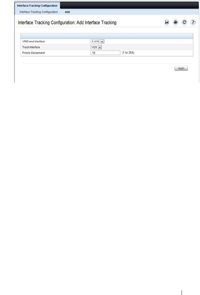
Configuring VRRP 1229
Figure 37-8. VRRP Interface Tracking Configuration
2
Select the virtual router ID and VLAN routing interface that will track the
interface.
3
Specify the interface to track.
4
Specify a value for the
Priority Decrement
to define the amount that the
router priority will be decreased when a tracked interface goes down.
5.
Click
Apply
to update the switch.

1230 Configuring VRRP
Configuring VRRP Features (CLI)
This section provides information about the commands you use to configure
VRRP settings on the switch. For more information about the commands, see
the
Dell Networking N2000, N3000, and N4000 Series Switches CLI
Reference Guide
at support.dell.com/manuals.
Configuring VRRP Settings
Beginning in Privileged EXEC mode, use the following commands to
configure switch and interface VRRP settings. This set of commands also
describes how to configure VRRP interface and route tracking.
Command Purpose
configure Enter global configuration mode.
ip vrrp Enable the administrative mode of VRRP for the router
(L3 switch).
interface vlan
vlan-id
Enter Interface Configuration mode for the specified
VLAN.
vrrp
vr-id
Allow the interface to create in the VRRP group specified
by the
vr-id
parameter, which is a number from 1–255.
vrrp
vr-id
description (Optional) Create a text description that identifies the
VRRP group.
vrrp
vr-id
preempt [delay
seconds
]
Enable the preemption mode value for the virtual router
configured on a specified interface.
You can optionally configure a preempt delay, which is the
number of seconds the VRRP router waits before the
VRRP router sends an advertisement to claim master
ownership.
vrrp
vr-id
accept-mode Allow the VRRP master to accept ping packets sent to one
of the virtual router’s IP addresses.
vrrp
vr-id
priority
priority
Set the priority value for the virtual router configured on
the interface.
vrrp
vr-id
ip
ip-address
[secondary]
Set the virtual router IP address value for an interface.

Configuring VRRP 1231
vrrp
vr-id
timers {learn |
advertise
seconds
}
Configure the VRRP timer settings.
Use the keyword learn to enable VRRP to learn the
advertisement timer interval of the master router.
Use the keyword advertise to set the frequency, in seconds,
that an interface on the specified virtual router sends a
virtual router advertisement.
vrrp
vr-id
authentication
{none | simple
key
}
Set the authorization details value for the virtual router
configured on a specified interface.
•
vr-id
— The virtual router identifier. (Range: 1-255)
•
none
— Indicates authentication type is none.
•
simple
— Authentication type is a simple text password.
•
key
— The key for simple authentication. (Range: String
values)
vrrp
vr-id
mode Enable the virtual router configured on an interface, which
starts the virtual router.
vrrp
vr-id
track interface
vlan
vlan-id
[decrement
priority
]
Specify an interface the virtual router (
vr-id
)
on the
interface will track. If the interface goes down, the virtual
router priority is decreased by the amount specified by the
priority
value.
vrrp
vr-id
track ip route
ip-address/prefix-length
[decrement
priority
]
Specify a route that the virtual router (
vr-id
)
on the
interface will track. If the route to the destination network
specified by the
ip-address/prefix-length
variable is
removed from the routing table, the virtual router priority
is decreased by the amount specified by the
priority
value.
CTRL + Z Exit to Privileged EXEC mode.
show vrrp [
vr-id
]View settings for all VRRP groups or for the specified
VRRP group for the switch.
show vrrp brief View a summary of interfaces configured to participate in
VRRP groups.
show vrrp interface
{brief | vlan
vlan-id
[stats]}
View information about VRRP settings configured on all
interfaces or on the specified interface. If you specify an
interface, use the keyword stats to view VRRP statistics for
the interface.
Command Purpose

1232 Configuring VRRP
VRRP Configuration Example
This section contains the following VRRP examples:
• VRRP with Load Sharing
• VRRP with Route and Interface Tracking
VRRP with Load Sharing
In Figure 37-9, two L3 Dell Networking switches are performing the routing
for network clients. Router A is the default gateway for some clients, and
Router B is the default gateway for other clients.
Figure 37-9. VRRP with Load Sharing Network Diagram

Configuring VRRP 1233
This example configures two VRRP groups on each router. Router A is the
VRRP master for the VRRP group with VRID 10 and the backup for VRID 20.
Router B is the VRRP master for VRID 20 and the backup for VRID 10. If
Router A fails, Router B will become the master of VRID 10 and will use the
virtual IP address 192.168.10.1. Traffic from the clients configured to use
Router A as the default gateway will be handled by Router B.
To configure Router A:
1
Enable routing for the switch.
console#config
console(config)#ip routing
2
Create and configure the VLAN routing interface to use as the default
gateway for network clients. This example assumes all other routing
interfaces, such as the interface to the external network, have been
configured.
console(config)#interface vlan 10
console(config-if-vlan10)#ip address 192.168.10.1 255.255.255.0
console(config-if-vlan10)#exit
3
Enable VRRP for the switch.
console(config)#ip vrrp
4
Assign a virtual router ID to the VLAN routing interface for the first VRRP
group.
console(config)#interface vlan 10
console(config-if-vlan10)#vrrp 10
5
Specify the IP address that the virtual router function will use. The router
is the virtual IP address owner (the routing interface has the same IP
address as the virtual IP address for the VRRP group), so the priority value
is 255.
console(config-if-vlan10)#vrrp 10 ip 192.168.10.1
6
Configure an optional description to help identify the VRRP group.
console(config-if-vlan10)#vrrp 10 description master
7
Assign a virtual router ID to the VLAN routing interface for the second
VRRP group.
console(config-if-vlan10)#vrrp 20
8
Specify the IP address that the virtual router function will use.
console(config-if-vlan10)#vrrp 20 ip 192.168.10.2

1234 Configuring VRRP
9
Configure an optional description to help identify the VRRP group.
console(config-if-vlan10)#vrrp 20 description backup
10
Enable the VRRP groups on the interface.
console(config-if-vlan10)#vrrp 10 mode
console(config-if-vlan10)#vrrp 20 mode
console(config-if-vlan10)#exit
console(config)#exit
The only difference between the Router A and Router B configurations is the
IP address assigned to VLAN 10. On Router B, the IP address of VLAN 10 is
192.168.10.2. Because this is also the virtual IP address of VRID 20, Router B
is the interface owner and VRRP master of VRRP group 20.
To configure Router B:
1
Enable routing for the switch.
console#config
console(config)#ip routing
2
Create and configure the VLAN routing interface to use as the default
gateway for network clients. This example assumes all other routing
interfaces, such as the interface to the external network, have been
configured.
console(config)#interface vlan 10
console(config-if-vlan10)#ip address 192.168.10.2 255.255.255.0
console(config-if-vlan10)#exit
3
Enable VRRP for the switch.
console(config)#ip vrrp
4
Assign a virtual router ID to the VLAN routing interface for the first VRRP
group.
console(config)#interface vlan 10
console(config-if-vlan10)#vrrp 10
5
Specify the IP address that the virtual router function will use.
console(config-if-vlan10)#vrrp 10 ip 192.168.10.1
6
Configure an optional description to help identify the VRRP group.
console(config-if-vlan10)#vrrp 10 description master
7
Assign a virtual router ID to the VLAN routing interface for the second
VRRP group.
console(config-if-vlan10)#vrrp 20

Configuring VRRP 1235
8
Specify the IP address that the virtual router function will use.
The router is the virtual IP address owner of this address, so the priority
value is 255 by default.
console(config-if-vlan10)#vrrp 20 ip 192.168.10.2
9
Configure an optional description to help identify the VRRP group.
console(config-if-vlan10)#vrrp 20 description backup
10
Enable the VRRP groups on the interface.
console(config-if-vlan10)#vrrp 10 mode
console(config-if-vlan10)#vrrp 20 mode
console(config-if-vlan10)#exit
console(config)#exit
Troubleshooting VRRP
When configuring VRRP, ensure that the L2 network facing the VRRP router
is up. Both VRRP peers will show as being in the “Master” state until the
layer 2 network is operational. Likewise, ensure that the link or path between
the virtual routers is operational. If the link is not operational, one VR
instance will show as “Master” and the other VR instance will show as
“Initializing.” Check the spanning-tree state on the routed links. Routed links
must show as forwarding. Disable spanning tree on the routed links if
necessary to prevent spanning tree from blocking routed links.
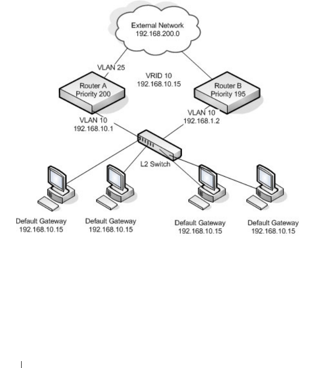
1236 Configuring VRRP
VRRP with Route and Interface Tracking
In Figure 37-10, the VRRP priorities are configured so that Router A is the
VRRP master, and Router B is the VRRP backup. Router A forwards IP traffic
from clients to the external network through the VLAN 25 routing interface.
The clients are configured to use the virtual IP address 192.168.10.15 as the
default gateway.
Figure 37-10. VRRP with Tracking Network Diagram
Without VRRP interface or route tracking, if something happened to VLAN
25 or the route to the external network, as long as Router A remains up, it will
continue to be the VRRP master even though traffic from the clients does not
have a path to the external network. However, if the interface and/or route
tracking features are configured, Router A can decrease its priority value when
the problems occur so that Router B becomes the master.

Configuring VRRP 1237
To configure Router A:
1
Enable routing for the switch.
console#config
console(config)#ip routing
2
Create and configure the VLAN routing interface to use as the default
gateway for network clients. This example assumes all other routing
interfaces, such as the interface to the external network, have been
configured.
console(config)#interface vlan 10
console(config-if-vlan10)#ip address 192.168.10.1 255.255.255.0
console(config-if-vlan10)#exit
3
Enable VRRP for the switch.
console(config)#ip vrrp
4
Assign a virtual router ID to the VLAN routing interface for the VRRP
group.
console(config)#interface vlan 10
console(config-if-vlan10)#vrrp 10
5
Specify the IP address that the virtual router function will use.
console(config-if-vlan10)#vrrp 10 ip 192.168.10.15
6
Configure the router priority.
console(config-if-vlan10)#vrrp 10 priority 200
7
Enable preempt mode so that the router can regain its position as VRRP
master if its priority is greater than the priority of the backup router.
console(config-if-vlan10)#vrrp 10 preempt
8
Enable the VRRP groups on the interface.
console(config-if-vlan10)#vrrp 10 mode
console(config-if-vlan10)#exit
9
Track the routing interface VLAN 25 on VRID 10 so that if it goes down,
the priority of VRID 10 on Router A is decreased by 10, which is the
default decrement priority value.
console(config-if-vlan10)#vrrp 10 track interface vlan 25
10
Track the route to the 192.168.200.0 network. If it becomes unavailable,
the priority of VRID 10 on Router A is decreased by 10, which is the
default decrement priority value.

1238 Configuring VRRP
console(config-if-vlan10)#vrrp 10 track ip route 192.168.200.0/24
console(config-if-vlan10)#exit
Router B is the backup router for VRID 10. The configured priority is 195. If
the VLAN 25 routing interface or route to the external network on Router A
go down, the priority of Router A will become 190 (or 180, if both the
interface and router are down). Because the configured priority of Router B is
greater than the actual priority of Router A, Router B will become the master
for VRID 10. When VLAN 25 and the route to the external network are back
up, the priority of Router A returns to 200, and it resumes its role as VRRP
master.
To configure Router B:
1
Enable routing for the switch.
console#config
console(config)#ip routing
2
Create and configure the VLAN routing interface to use as the default
gateway for network clients. This example assumes all other routing
interfaces, such as the interface to the external network, have been
configured.
console(config)#interface vlan 10
console(config-if-vlan10)#ip address 192.168.10.2 255.255.255.0
console(config-if-vlan10)#exit
3
Enable VRRP for the switch.
console(config)#ip vrrp
4
Assign a virtual router ID to the VLAN routing interface for the VRRP
group.
console(config)#interface vlan 10
console(config-if-vlan10)#vrrp 10
5
Specify the IP address that the virtual router function will use.
console(config-if-vlan10)#vrrp 10 ip 192.168.10.15
6
Configure the router priority.
console(config-if-vlan10)#vrrp 10 priority 195
7
Enable preempt mode so that the router can regain its position as VRRP
master if its priority is greater than the priority of the backup router.
console(config-if-vlan10)#vrrp 10 preempt

Configuring VRRP 1239
8
Enable the VRRP groups on the interface.
console(config-if-vlan10)#vrrp 10 mode
console(config-if-vlan10)#exit
console(config)#exit

1240 Configuring VRRP

Configuring IPv6 Routing 1241
38
Configuring IPv6 Routing
This chapter describes how to configure general IPv6 routing information on
the switch, including global routing settings and IPv6 static routes. The topics
covered in this chapter include:
• IPv6 Routing Overview
• Default IPv6 Routing Values
• Configuring IPv6 Routing Features (Web)
• Configuring IPv6 Routing Features (CLI)
The Dell Networking series switches support additional features to help
manage IPv6 networks, including OSPFv3, DHCPv6, and IPv6 multicast. For
information about OSPFv3, see "Configuring OSPF and OSPFv3" on
page 1111. For information about DHCPv6, see "Configuring DHCPv6
Server and Relay Settings" on page 1265. For information about IPv6
multicast, see "Managing IPv4 and IPv6 Multicast" on page 1337.
For configuration examples that include IPv6 interface configuration, see
"OSPF Configuration Examples" on page 1177
IPv6 Routing Overview
IPv6 is the next generation of the Internet Protocol. With 128-bit addresses,
versus 32-bit addresses for IPv4, IPv6 solves the address depletion issues seen
with IPv4 and removes the requirement for Network Address Translation
(NAT), which is used in IPv4 networks to reduce the number of globally
unique IP addresses required for a given network.
On the Dell Networking N2000, N3000, and N4000 series switches, IPv6
coexists with IPv4. As with IPv4, IPv6 routing can be enabled on loopback and
VLAN interfaces. Each L3 routing interface can be used for IPv4, IPv6, or
both. IP protocols running over L3 (for example, UDP and TCP) are common
to both IPv4 and IPv6.

1242 Configuring IPv6 Routing
How Does IPv6 Compare with IPv4?
There are many conceptual similarities between IPv4 and IPv6 network
operation. Addresses still have a network prefix portion (network) and a
device interface specific portion (host). While the length of the network
portion is still variable, most users have standardized on using a network
prefix length of 64 bits. This leaves 64 bits for the interface specific portion,
called an Interface ID in IPv6. Depending upon the underlying link
addressing, the Interface ID can be automatically computed from the link
(e.g., MAC address). Such an automatically computed Interface ID is called
an EUI-64 identifier, which is the interface MAC address with ff:fe inserted in
the middle.
IPv6 packets on the network are of an entirely different format than
traditional IPv4 packets and are also encapsulated in a different EtherType
(86DD rather than 0800 which is used with IPv4). The details for
encapsulating IPv6 in Ethernet frames are described in RFC2462.
Unlike IPv4, IPv6 does not have broadcasts. There are two types of IPv6
addresses — unicast and multicast. Unicast addresses allow direct one-to-one
communication between two hosts, whereas multicast addresses allow one-to-
many communication. Multicast addresses are used as destinations only.
Unicast addresses will have 00 through fe in the most significant octets and
multicast addresses will have ff in the most significant octets.
How Are IPv6 Interfaces Configured?
In Dell Networking N2000, N3000, and N4000 series switches software, IPv6
coexists with IPv4. As with IPv4, IPv6 routing can be enabled on VLAN
interfaces. Each L3 routing interface can be used for IPv4, IPv6, or both
simultaneously.
Neighbor Discovery (ND) protocol is the IPv6 replacement for Address
Resolution Protocol (ARP) in IPv4. The IPv6 Neighbor Discovery protocol is
described in detail in RFC4861. Router advertisement is part of the Neighbor
Discovery process and is required for IPv6. As part of router advertisement,
Dell Networking N2000, N3000, and N4000 series switches software supports
stateless auto configuration of end nodes. The switch supports both EUI-64
interface identifiers and manually configured interface IDs.

Configuring IPv6 Routing 1243
While optional in IPv4, router advertisement is mandatory in IPv6. Router
advertisements specify the network prefix(es) on a link which can be used by
receiving hosts, in conjunction with an EUI-64 identifier, to autoconfigure a
host’s address. Routers have their network prefixes configured and may use
EUI-64 or manually configured interface IDs. In addition to zero or more
global addresses, each IPv6 interface also has an autoconfigured “link-local”
address which is:
• fe80::/10, with the EUI-64 address in the least significant bits.
• Reachable only on the local VLAN — link-local addresses are never routed.
• Not globally unique
Next hop addresses computed by routing protocols are usually link-local
addresses.
During the period of transitioning the Internet to IPv6, a global IPv6 Internet
backbone may not be available. One transition mechanism is to tunnel IPv6
packets inside IPv4 to reach remote IPv6 islands. When a packet is sent over
such a link, it is encapsulated in IPv4 in order to traverse an IPv4 network and
has the IPv4 headers removed at the other end of the tunnel.
Default IPv6 Routing Values
IPv6 is disabled by default on the switch and on all interfaces.
Table 38-1 shows the default values for the IP routing features this chapter
describes.
Table 38-1. IPv6 Routing Defaults
Parameter Default Value
IPv6 Unicast Routing Mode Disabled
IPv6 Hop Limit Unconfigured
ICMPv6 Rate Limit Error Interval 1000 milliseconds
ICMPv6 Rate Limit Burst Size 100
Interface IPv6 Mode Disabled

1244 Configuring IPv6 Routing
Table 38-2 shows the default IPv6 interface values after a VLAN routing
interface has been created.
IPv6 Router Route Preferences Local—0
Static—1
OSPFv3 Intra—110
OSPFv3 Inter—110
OSPFv3 External—110
Table 38-2. IPv6 Interface Defaults
Parameter Default Value
IPv6 Mode Disabled
DHCPv6 Client Mode Disabled
Stateless Address AutoConfig Mode Disabled
Routing Mode Enabled
Interface Maximum Transmit Unit 1500
Router Duplicate Address Detection Transmits 1
Router Advertisement NS Interval Not configured
Router Lifetime Interval 1800 seconds
Router Advertisement Reachable Time 0 seconds
Router Advertisement Interval 600 seconds
Router Advertisement Managed Config Flag Disabled
Router Advertisement Other Config Flag Disabled
Router Advertisement Suppress Flag Disabled
IPv6 Destination Unreachables Enabled
Table 38-1. IPv6 Routing Defaults (Continued)
Parameter Default Value

Configuring IPv6 Routing 1245
Configuring IPv6 Routing Features (Web)
This section provides information about the OpenManage Switch
Administrator pages for configuring and monitoring IPv6 unicast routing
features on a Dell Networking N2000, N3000, and N4000 series switches. For
details about the fields on a page, click at the top of the page.
Global Configuration
Use the Global Configuration
page to enable IPv6 forwarding on the router,
enable the forwarding of IPv6 unicast datagrams, and configure global IPv6
settings.
To display the page, click Routing
→
IPv6
→
Global Configuration in the
navigation panel.
Figure 38-1. IPv6 Global Configuration
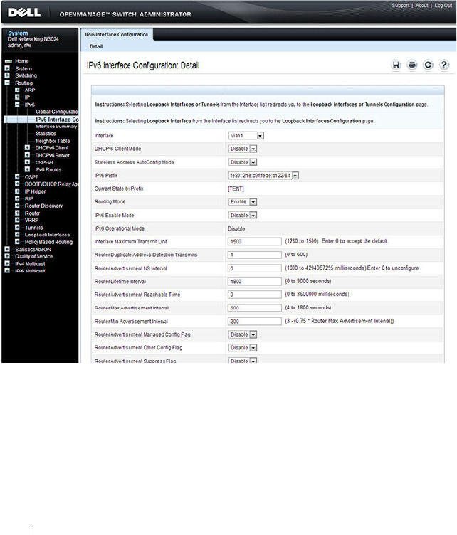
1246 Configuring IPv6 Routing
Interface Configuration
Use the Interface Configuration
page to configure IPv6 interface parameters.
This page has been updated to include the IPv6 Destination Unreachables
field.
To display the page, click Routing
→
IPv6
→
Interface Configuration in the
navigation panel.
Figure 38-2. IPv6 Interface Configuration
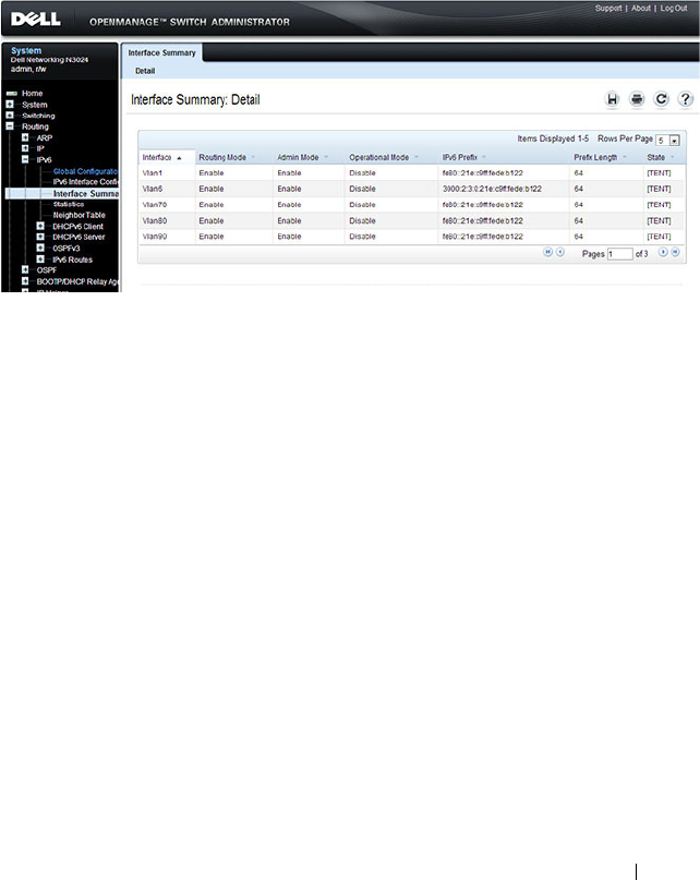
Configuring IPv6 Routing 1247
Interface Summary
Use the Interface Summary
page to display settings for all IPv6 interfaces.
To display the page, click Routing
→
IPv6
→
Interface Summary in the
navigation panel.
Figure 38-3. IPv6 Interface Summary
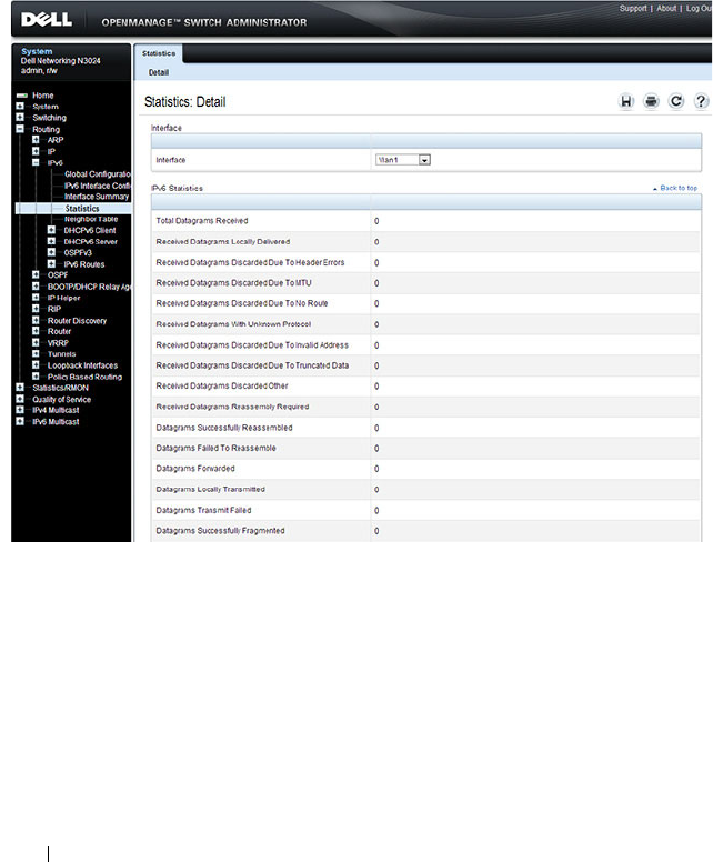
1248 Configuring IPv6 Routing
IPv6 Statistics
Use the IPv6 Statistics
page to display IPv6 traffic statistics for one or all
interfaces.
To display the page, click Routing
→
IPv6
→
IPv6 Statistics in the navigation
panel.
Figure 38-4. IPv6 Statistics
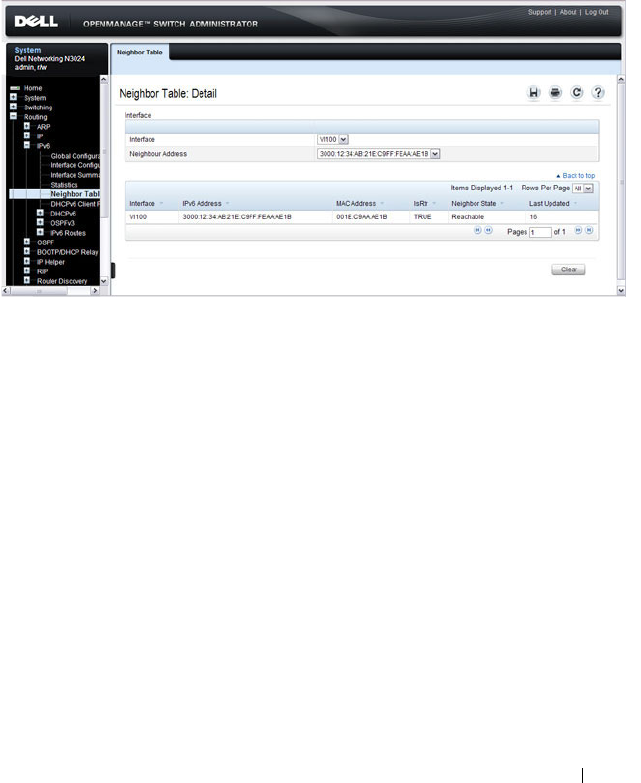
Configuring IPv6 Routing 1249
IPv6 Neighbor Table
Use the IPv6 Neighbor Table
page to display IPv6 neighbor details for a
specified interface.
To display the page, click IPv6
→
IPv6 Neighbor Table in the navigation
panel.
Figure 38-5. IPv6 Neighbor Table
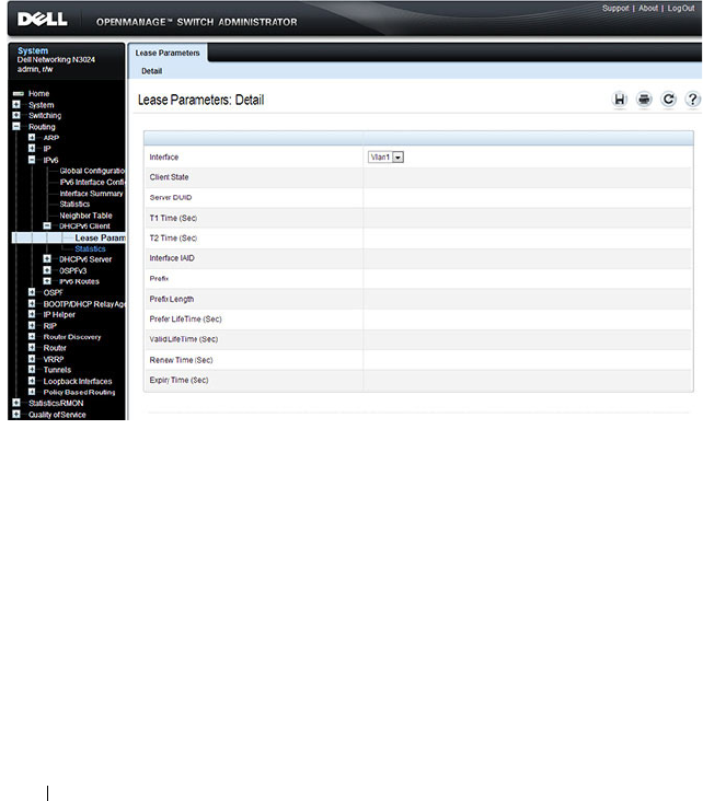
1250 Configuring IPv6 Routing
DHCPv6 Client Parameters
Use the DHCPv6 Client Parameters
page to view information about the
network information automatically assigned to an interface by the DHCPv6
server. This page displays information only if the DHCPv6 client has been
enabled on an IPv6 routing interface.
To display the page, click Routing
→
IPv6
→
DHCPv6 Client > Lease
Parameters in the navigation panel.
Figure 38-6. DHCPv6 Lease Parameters
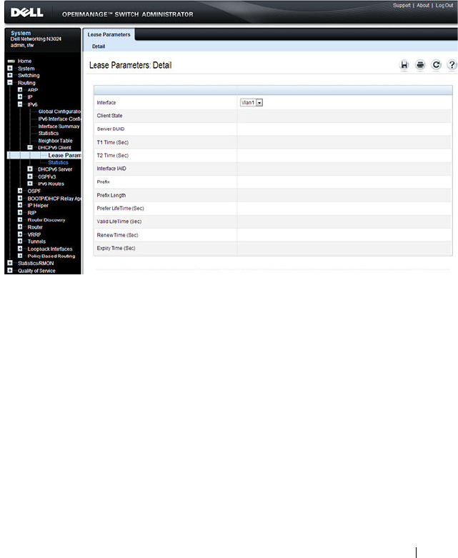
Configuring IPv6 Routing 1251
DHCPv6 Client Statistics
Use the DHCPv6 Client Statistics page to view information about DHCPv6
packets received and transmitted on a DHCPv6 client interface.
To display the page, click Routing
→
IPv6
→
DHCPv6 Client > Statistics in
the navigation panel.
Figure 38-7. DHCPv6 Lease Parameters
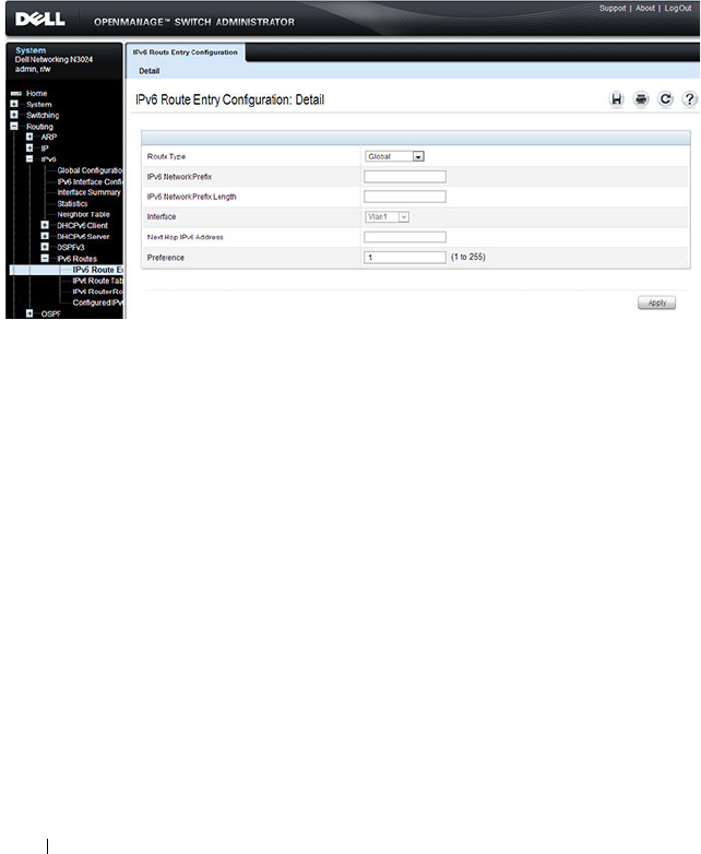
1252 Configuring IPv6 Routing
IPv6 Router Entry Configuration
Use the IPv6 Route Entry Configuration
page to configure information for
IPv6 routes.
To display the page, click Routing
→
IPv6
→
IPv6 Routes
→
IPv6 Route
Entry Configuration in the navigation panel.
Figure 38-8. IPv6 Route Entry Configuration
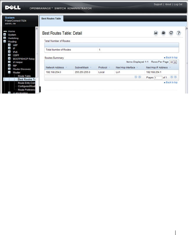
Configuring IPv6 Routing 1253
IPv6 Route Table
Use the IPv6 Route Table
page to display all active IPv6 routes and their
settings.
To display the page, click Routing
→
IPv6
→
IPv6 Routes
→
IPv6 Route
Table in the navigation panel.
Figure 38-9. IPv6 Route Table
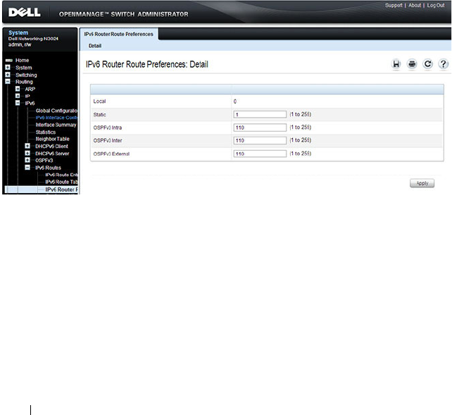
1254 Configuring IPv6 Routing
IPv6 Route Preferences
Use the IPv6 Route Preferences
page to configure the default preference for
each protocol. These values are arbitrary values in the range of 1 to 255 and
are independent of route metrics. Most routing protocols use a route metric
to determine the shortest path known to the protocol, independent of any
other protocol. The best route to a destination is chosen by selecting the
route with the lowest preference value. When there are multiple routes to a
destination, the preference values are used to determine the preferred route.
If there is still a tie, the route with the best route metric is chosen. To avoid
problems with mismatched metrics, you must configure different preference
values for each of the protocols.
To display the page, click Routing
→
IPv6
→
IPv6 Routes
→
IPv6 Route
Preferences in the navigation panel.
Figure 38-10. IPv6 Route Preferences
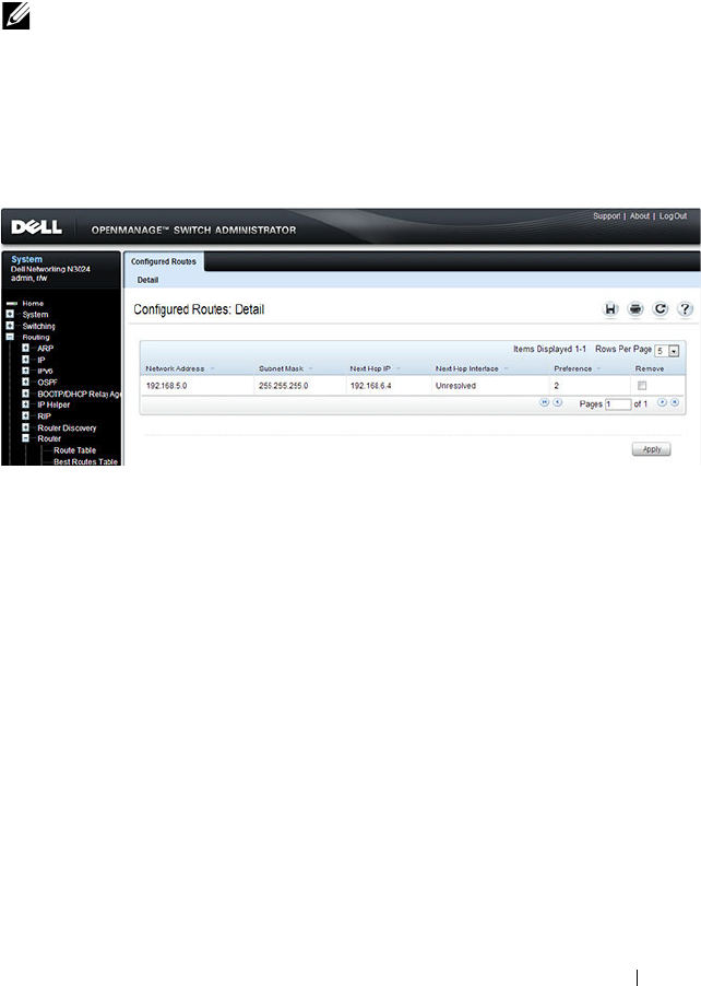
Configuring IPv6 Routing 1255
Configured IPv6 Routes
Use the Configured IPv6 Routes
page to display selected IPv6 routes.
To display the page, click Routing
→
IPv6
→
IPv6 Routes
→
Configured
IPv6 Routes in the navigation panel.
Figure 38-11. Configured IPv6 Routes
To remove a configured route, select the check box in the Delete column of
the route to remove, and click Apply.
NOTE: For a static reject route, the next hop interface value is Null0. Packets to
the network address specified in static reject routes are intentionally dropped.

1256 Configuring IPv6 Routing
Configuring IPv6 Routing Features (CLI)
This section provides information about the commands you use to configure
IPv6 routing on the switch. For more information about the commands, see
the
Dell Networking N2000, N3000, and N4000 Series Switches CLI
Reference Guide
at support.dell.com/manuals.
Configuring Global IP Routing Settings
Beginning in Privileged EXEC mode, use the following commands to
configure various global IP routing settings for the switch.
Command Purpose
configure Enter global configuration mode.
sdm prefer dual-ipv4-
and-ipv6 default
Select a Switch Database Management (SDM) template
to enable support for both IPv4 and IPv6. Changing the
SDM template requires a system reload.
ipv6 unicast-routing Globally enable IPv6 routing on the switch.
ipv6 hop-limit
limit
Set the TTL value for the router. The valid range is 0 to
255.
ipv6 icmp error-interval
burst-interval
[
burst-
size
]
Limit the rate at which IPv4 ICMP error messages are sent.
•
burst-interval
— How often the token bucket is
initialized (Range: 0–2147483647 milliseconds).
•
burst-size
— The maximum number of messages that
can be sent during a burst interval (Range: 1–200).
exit Exit to Privileged EXEC mode.

Configuring IPv6 Routing 1257
Configuring IPv6 Interface Settings
Beginning in Privileged EXEC mode, use the following commands to
configure IPv6 settings for VLAN, tunnel, or loopback interfaces.
Command Purpose
configure Enter Global Configuration mode.
interface {vlan |
tunnel | loopback}
interface-id
Enter Interface Configuration mode for the specified VLAN,
tunnel, or loopback interface.
ipv6 enable Enable IPv6 on the interface. Configuring an IPv6 address
will automatically enable IPv6 on the interface.
ipv6 address
{autoconfig | dhcp |
prefix/prefix-length
[eui64]}
Configure the IPv6 address and network prefix length.
Setting an IPv6 address enables IPv6 on the interface. You
can also use the ipv6 enable command to enable IPv6 on the
interface without setting an address.
Link-local, multicast, IPv4-compatible, and IPv4-mapped
addresses are not allowed to be configured.
Include the EUI-64 keyword to have the system add the 64-
bit interface ID to the address. You must use a network prefix
length of 64 in this case.
For VLAN interfaces, use the dhcp keyword to enable the
DHCPv6 client and obtain an IP address form a network
DHCPv6 server.
ipv6 traffic-filter
ACL
name
Add an access-list filter to this interface.
ipv6 unreachables (VLAN interfaces only) Allow the interface to send ICMPv6
Destination Unreachable messages. The no ipv6
unreachables command suppresses the ICMPv6 unreachable
messages for this interface.
exit Exit the interface configuration mode.

1258 Configuring IPv6 Routing
Configuring IPv6 Neighbor Discovery
Use the following commands to configure IPv6 Neighbor Discovery settings.
Command Purpose
ipv6 nd prefix
prefix/prefix-length
[{
valid-lifetime
|
infinite} {
preferred-
lifetime
| infinite}]
[no-autoconfig] [off-
link]
Configure parameters associated with network prefixes that
the router advertises in its Neighbor Discovery
advertisements.
• ipv6-prefix—IPv6 network prefix.
•
prefix-length
—IPv6 network prefix length.
•
valid-lifetime
—Valid lifetime of the router in seconds.
(Range: 0–4294967295 seconds.)
•
infinite
—Indicates lifetime value is infinite.
•
preferred-lifetime
—Preferred-lifetime of the router in
seconds. (Range: 0–4294967295 seconds.)
•
no-autoconfig
—Do not use the prefix for auto
configuration.
•
off-link
—Do not use the prefix for onlink determination.
ipv6 nd ra-interval
maximum
minimum
Set the transmission interval between router Neighbor
Discovery advertisements.
•
maximum
— The maximum interval duration (Range:
4–1800 seconds).
•
minimum
— The minimum interval duration (Range: 3 –
(0.75 * maximum) seconds).
ipv6 nd ra-lifetime
seconds
Set the value that is placed in the Router Lifetime field of
the router Neighbor Discovery advertisements sent from the
interface.
The
seconds
value must be zero, or it must be an integer
between the value of the router advertisement transmission
interval and 9000 seconds. A value of zero means this router
is not to be used as the default router. (Range: 0-9000).
ipv6 nd suppress-ra Suppress router advertisement transmission on an interface.
ipv6 nd dad attempts
value
Set the number of duplicate address detection probes
transmitted while doing Neighbor Discovery.
The range for
value
is 0–600.

Configuring IPv6 Routing 1259
ipv6 nd ns-interval
milliseconds
Set the interval between router advertisements for advertised
neighbor solicitations. The range is 1000 to 4294967295
milliseconds.
ipv6 nd other-config-
flag
Set the
other stateful configuration
flag in router
advertisements sent from the interface.
ipv6 nd managed-
config-flag
Set the
managed address configuration
flag in router
advertisements. When the value is true, end nodes use
DHCPv6. When the value is false, end nodes automatically
configure addresses.
ipv6 nd reachable-
time
milliseconds
Set the router advertisement time to consider a neighbor
reachable after neighbor discovery confirmation.
Command Purpose

1260 Configuring IPv6 Routing
Configuring IPv6 Route Table Entries and Route Preferences
Beginning in Privileged EXEC mode, use the following commands to
configure IPv6 Static Routes.
Command Purpose
configure Enter global configuration mode.
ipv6 route
ipv6-
prefix/prefix-length
{
next-
hop-address
|
interface-
type interface-number
next-hop-address
}
[
preference
]
Configure a static route.Use the keyword null instead of
the next hop router IP address to configure a static reject
route.
•
prefix/prefix-length
—The IPv6 network prefix and
prefix length that is the destination of the static route.
Use the ::/0 form (unspecified address and zero length
prefix) to specify a default route.
•
interface-type interface-number
—Must be specified
when using a link-local address as the next hop. The
interface-type can be
vlan
or
tunnel
.
•
next-hop-address
—The IPv6 address of the next hop
that can be used to reach the specified network. A link-
local next hop address must have a prefix length of 128.
The next hop address cannot be an unspecified address
(all zeros), a multicast address, or a loopback address. If
a link local next hop address is specified, the interface
(VLAN or tunnel), must also be specified.
•
preference
—Also known as Administrative Distance, a
metric the router uses to compare this route with routes
from other route sources that have the same network
prefix. (Range: 1-255). Lower values have precedence
over higher values. The default preference for static
routes is 1. Routes with a preference of 255 are
considered as “disabled” and will not be used for
forwarding. Routes with a preference metric of 254 are
used by the local router but will never be advertised to
other neighboring routers.
ipv6 route
ipv6-
prefix
/
prefix-length
null
[
preference
]
Configure a static reject route. IPv6 packets matching
the reject route will be silently discarded.

Configuring IPv6 Routing 1261
ipv6 route distance
integer
Set the default distance (preference) for static IPv6
routes. Lower route preference values are preferred when
determining the best route. The default distance
(preference) for static routes is 1.
exit Exit to Global Config mode.
Command Purpose

1262 Configuring IPv6 Routing
IPv6 Show Commands
Use the following commands in Privileged EXEC mode to view IPv6
configuration status and related data.
Command Purpose
show sdm prefer Show the currently active SDM template.
show sdm prefer dual-
ipv4-and-ipv6 default
Show parameters for the SDM template.
show ipv6 dhcp interface
vlan
vlan-id
View information about the DHCPv6 lease acquired by
the specified interface.
show ipv6 interface {vlan
| tunnel | loopback}
interface-id
View the IP interface configuration information for the
specified IPv6 routing interface.
show ipv6 brief View the global IPv6 settings for the switch.
show ipv6 route [
ipv6-
address
|
ipv6-
prefix/prefix-length
|
protocol
|
interface-type
interface-number
] [best]
View the routing table.
•
ipv6-address
—Specifies an IPv6 address for which the
best-matching route would be displayed.
•
protocol
—Specifies the protocol that installed the
routes. Is one of the following keywords: connected,
ospf, static.
•
ipv6-prefix/ prefix-length
—Specifies an IPv6 network
for which the matching route would be displayed.
•
interface-type interface-number
—Valid IPv6 interface.
Specifies that the routes with next-hops on the selected
interface be displayed.
•
best
—Specifies that only the best routes are displayed.
If the connected keyword is selected for protocol, the
best option is not available because there are no best or
non-best connected routes.
show ipv6 route summary View summary information about the IPv6 routing table.
show ipv6 route
preferences
View detailed information about the IPv6 route
preferences.

Configuring IPv6 Routing 1263
IPv6 Static Reject and Discard Routes
A static configured route with a next-hop of “null” causes any packet
matching the route to disappear or vanish from the network. This type of
route is called a “Discard” route if the router returns an ICMP “network-
unreachable” message, or is called a “Reject” route if no ICMP message is
returned. The Dell Networking series switches support “Reject” routes, where
any packets matching the route network prefix silently disappear.
A common use of a Reject route is to quickly discard packets that cannot be
delivered because a valid route to the destination is not known. Without the
Reject route, these undeliverable packets will continue to circulate through
the network, following the default routes, until their TTL expires. Forwarding
packets that cannot be delivered wastes bandwidth, particularly on expensive
WAN connections. The Reject route will also suppress a type of “Denial of
Service” (DoS) attack where an internal host sends large numbers of packets
to unknown destinations, causing congestion of the WAN links.
• ipv6 route ::/0 null 254
Use this in all routers except the ones with direct Internet connectivity.
Routers with direct Internet connectivity should advertise a default route.
The effect of this route is that when a router does not have connectivity to
the Internet, the router will quickly discard packets that it cannot deliver.
If the router learns a default route from another router, the learned route
will have a lower distance metric and therefore a higher preference. Routes
that are more specific (have more bits in the prefix) will have precedence
over less specific routes. This will cause packets destined for non-existent
networks to be quickly discarded. Also, because of the high distance metric
(254), this route will never be advertised to any neighbor routers.
• ipv6 route fc00::/7 null 254
This route covers the entire ULA (IPv6 private) address space. If you have
networks configured in this address space, you will have more specific
routes for those networks. The more specific routes (more bits of prefix)
will have precedence over this route. Any destinations in this range not
known via another, more specific route do not exist. The effect is that
packets destined for private networks that do not exist in your network will
be quickly discarded instead of being forwarded to the default route.

1264 Configuring IPv6 Routing
• ipv6 route 2001::/16 null 254
ipv6 route 2002::/16 null 254
These address ranges are reserved and not reachable in the Internet. If for
some reason you have local networks in this range, a more specific route
will have precedence.
Another use for the Reject route is to prevent internal hosts from
communication with specific addresses or ranges of addresses. The effect is
the same as an outgoing access-list with a “deny” statement. A route is
generally more efficient than an access-list that performs the same function.
If you need more fine-grained filtering, such as protocols or port numbers, use
the access-list instead.

Configuring DHCPv6 Server and Relay Settings 1265
39
Configuring DHCPv6 Server and
Relay Settings
This chapter describes how to configure the switch to dynamically assign
network information to IPv6 hosts by using the Dynamic Host Configuration
Protocol for IPv6 (DHCPv6).
The topics covered in this chapter include:
• DHCPv6 Overview
• Default DHCPv6 Server and Relay Values
• Configuring the DHCPv6 Server and Relay (Web)
• Configuring the DHCPv6 Server and Relay (CLI)
• DHCPv6 Configuration Examples
DHCPv6 Overview
DHCP is a protocol that is generally used between clients and servers for the
purpose of assigning IP addresses, gateways, and other networking definitions
such as Domain Name System (DNS) and Network Time Protocol (NTP)
parameters. However, IPv6 natively provides IP address auto configuration
through IPv6 Neighbor Discovery Protocol (NDP) and through the use of
Router Advertisement messages. Thus, the role of DHCPv6 within the
network is different than that of DHCPv4 because DHCPv6 is not the
primary source for IP address assignment.
DHCPv6 server and client interactions are described by RFC 3315 [6]. There
are many similarities between DHCPv6 and DHCPv4 interactions and
options, but there are enough differences in the messages and option
definitions that there is no DHCPv4 to DHCPv6 migration or
interoperability.

1266 Configuring DHCPv6 Server and Relay Settings
What Is a DHCPv6 Pool?
DHCPv6 pools are used to specify information for DHCPv6 server to
distribute to DHCPv6 clients. These pools are shared between multiple
interfaces over which DHCPv6 server capabilities are configured.
What Is a Stateless Server?
DHCPv6 incorporates the notion of the
stateless
server, where DHCPv6 is
not used for IP address assignment to a client; rather, it provides other
networking information such as DNS or NTP information. The stateless
server behavior is described by RFC 3736 [7], which simply contains
descriptions of the portions of RFC 3315 that are necessary for stateless server
behavior. In order for a router to drive a DHCPv6 client to utilize stateless
DHCPv6, the
other stateful configuration
option must be configured for
neighbor discovery on the corresponding IPv6 router interface. This, in turn,
causes DHCPv6 clients to send the DHCPv6 Information Request message
in response. A DHCPv6 server then responds by providing only networking
definitions such as DNS domain name and server definitions, NTP server
definitions, or SIP definitions.
What Is the DHCPv6 Relay Agent Information Option?
The DHCPv6 Relay Agent Information Option allows for various sub-options
to be attached to messages that are being relayed by the local router to a
DHCPv6 server. The DHCPv6+ server may in turn use this information in
determining an address to assign to a DHCPv6 client.RFC 3315 also
describes DHCPv6 Relay Agent interactions, which are very much like
DHCPv4 Relay Agents. Additionally, there is a DHCPv6 Relay Agent Option
described in RFC 4649, which employs very similar capabilities as those
described by the DHCPv4 Relay Agent Option in RFC 2132.
What Is a Prefix Delegation?
With the larger address space inherent to IPv6, addresses within a network
can be allocated more effectively in a hierarchical fashion. DHCPv6
introduces the notion of prefix delegation as described in RFC 3633 as a way
for routers to centralize and delegate IP address assignment. Figure 39-1
depicts a typical network scenario where prefix delegation is used.
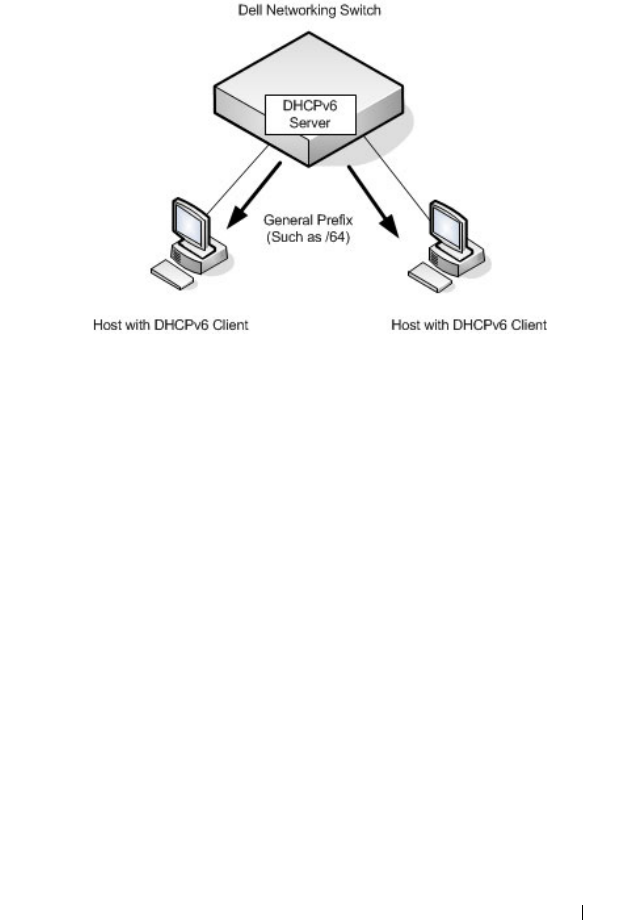
Configuring DHCPv6 Server and Relay Settings 1267
Figure 39-1. DHCPv6 Prefix Delegation Scenario
In Figure 39-1, the Dell Networking acts as the Prefix Delegation (PD) server
and defines one or more
general
prefixes to allocate and assign addresses to
hosts that may be utilizing IPv6 auto-address configuration or acting as
DHCPv6 clients.
DHCPv6 clients may request multiple IPv6 prefixes. Also, DHCPv6 clients
may request specific IPv6 prefixes. If the configured DHCPv6 pool contains
the specific prefix that a DHCPv6 client requests, then that prefix will be
delegated to the client. Otherwise, the first available IPv6 prefix within the
configured pool will be delegated to the client.
Default DHCPv6 Server and Relay Values
By default, the DHCPv6 server is disabled, and no address pools are
configured. VLAN routing interfaces are not configured to perform DHCPv6
server or DHCPv6 relay functions.
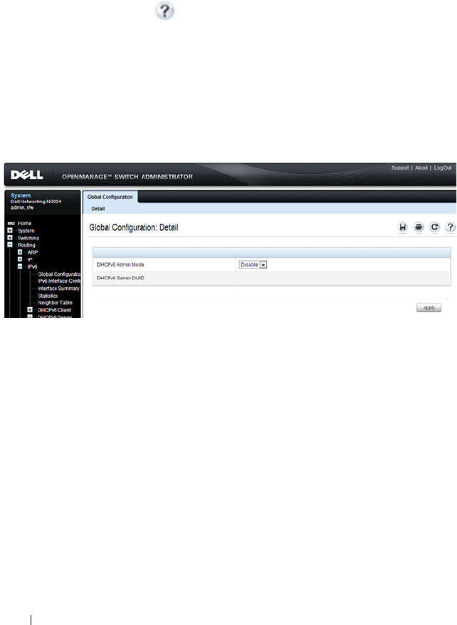
1268 Configuring DHCPv6 Server and Relay Settings
Configuring the DHCPv6 Server and Relay (Web)
This section provides information about the OpenManage Switch
Administrator pages for configuring and monitoring the DHCPv6 server on a
Dell Networking N2000, N3000, and N4000 series switches. For details about
the fields on a page, click at the top of the page.
DHCPv6 Global Configuration
Use the Global Configuration
page to configure DHCPv6 global parameters.
To display the page, click Routing
→
IPv6
→
DHCPv6 Server
→
Global
Configuration in the navigation panel.
Figure 39-2. DHCPv6 Global Configuration
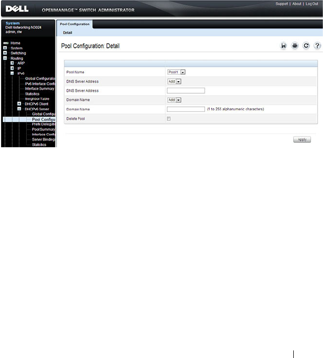
Configuring DHCPv6 Server and Relay Settings 1269
DHCPv6 Pool Configuration
Use the Pool Configuration page to set up a pool of DHCPv6 parameters for
DHCPv6 clients. The pool is identified with a pool name and contains IPv6
addresses and domain names of DNS servers.
To display the page, click Routing
→
IPv6
→
DHCPv6
→
Pool
Configuration in the navigation panel. Figure 39-3 shows the page when no
pools have been created. After a pool has been created, additional fields
display.
Figure 39-3. Pool Configuration
Configuring a DHCPv6 Pool
To configure the pool:
1
Open the
Pool Configuration
page.
2
Select
Create
from the
Pool Name
menu and type a name in the
Pool
Name
text box.
3
Click
Apply
.
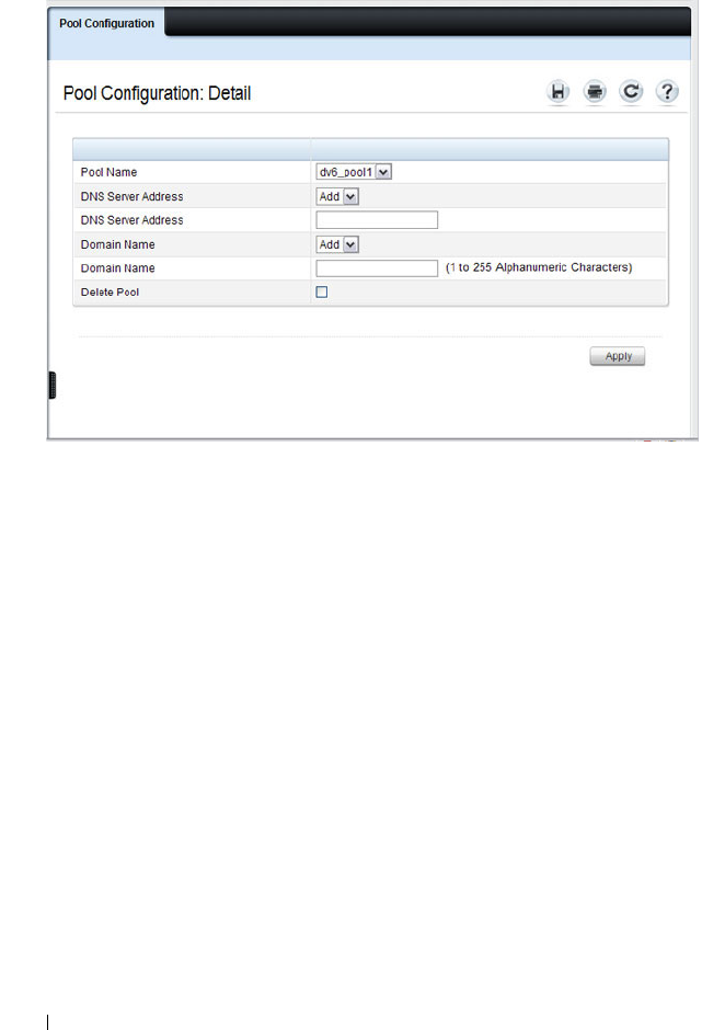
1270 Configuring DHCPv6 Server and Relay Settings
Figure 39-4. Pool Configuration
4
From the
DNS Server Address
menu, select an existing DNS Server
Address to associate with this pool, or select
Add
and specify a new server
to add.
5
From the
Domain Name
menu, select an existing domain name to
associate with this pool, or select
Add
and specify a new domain name.
6
Click
Apply
.
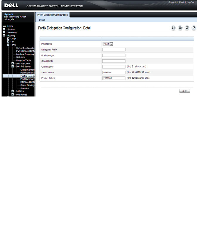
Configuring DHCPv6 Server and Relay Settings 1271
Prefix Delegation Configuration
Use the Prefix Delegation Configuration
page to configure a delegated prefix
for a pool. At least one pool must be created using DHCPv6 Pool
Configuration before a delegated prefix can be configured.
To display the page, click Routing
→
IPv6
→
DHCPv6
→
Prefix Delegation
Configuration in the navigation panel.
Figure 39-5. Prefix Delegation Configuration
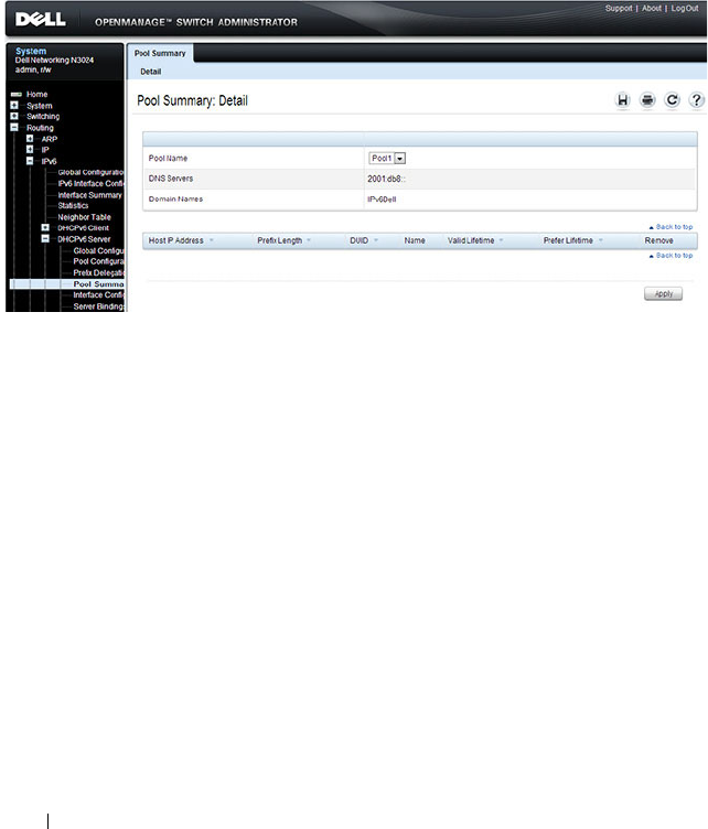
1272 Configuring DHCPv6 Server and Relay Settings
DHCPv6 Pool Summary
Use the Pool Summary
page to display settings for all DHCPv6 Pools. At least
one pool must be created using DHCPv6 Pool Configuration before the Pool
Summary displays.
To display the page, click Routing
→
IPv6
→
DHCPv6
→
Pool Summary in
the navigation panel.
Figure 39-6. Pool Summary
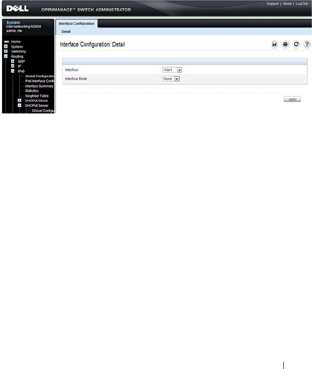
Configuring DHCPv6 Server and Relay Settings 1273
DHCPv6 Interface Configuration
Use the DHCPv6 Interface Configuration
page to configure a DHCPv6
interface.
To display the page, click Routing
→
IPv6
→
DHCPv6
→
Interface
Configuration in the navigation panel. The fields that display on the page
depend on the selected interface mode.
Figure 39-7. DHCPv6 Interface Configuration
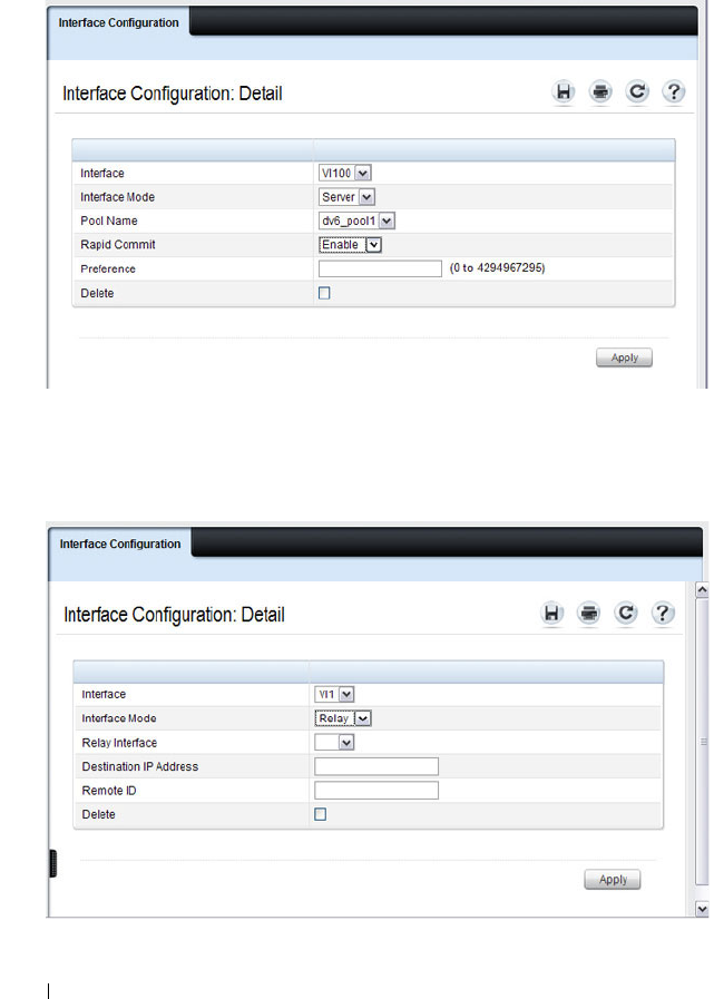
1274 Configuring DHCPv6 Server and Relay Settings
Figure 39-8 shows the screen when the selected interface mode is Server.
Figure 39-8. DHCPv6 Interface Configuration - Server Mode
Figure 39-9 shows the screen when the selected interface mode is Relay.
Figure 39-9. DHCPv6 Interface Configuration - Relay Mode
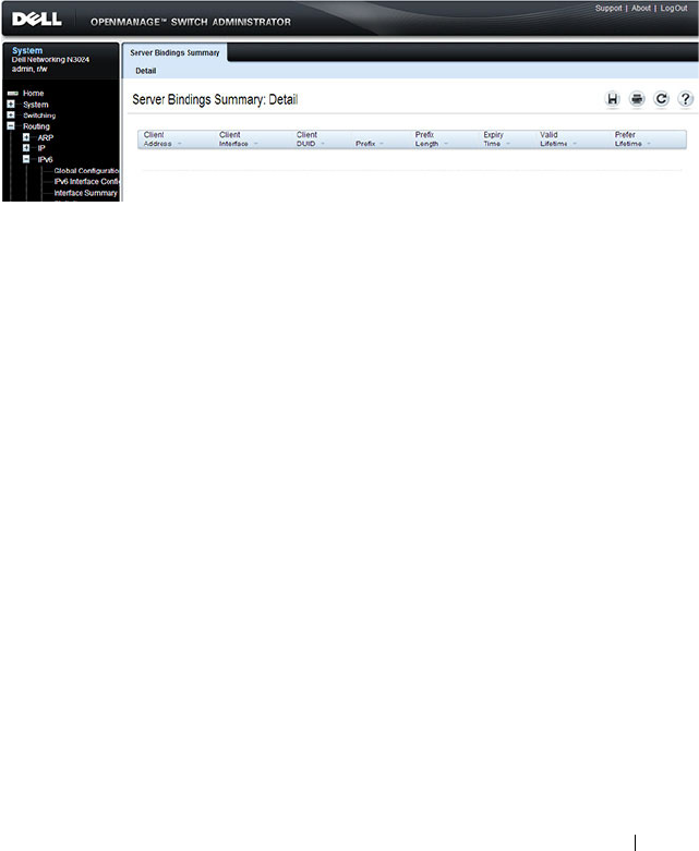
Configuring DHCPv6 Server and Relay Settings 1275
DHCPv6 Server Bindings Summary
Use the Server Bindings Summary
page to display all DHCPv6 server
bindings.
To display the page, click Routing
→
IPv6
→
DHCPv6
→
Bindings
Summary in the navigation panel.
Figure 39-10. Server Bindings Summary
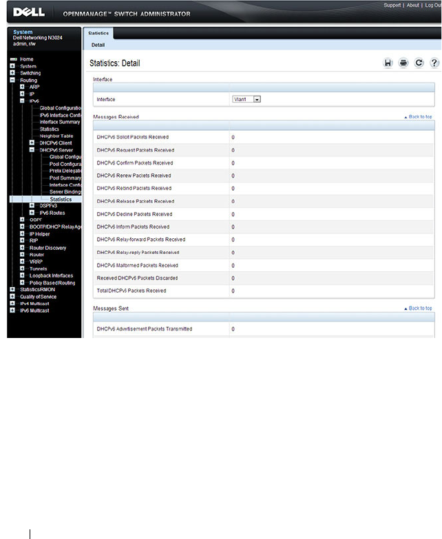
1276 Configuring DHCPv6 Server and Relay Settings
DHCPv6 Statistics
Use the DHCPv6 Statistics
page to display DHCPv6 statistics for one or all
interfaces.
To display the page, click Routing
→
IPv6
→
DHCPv6
→
Statistics in the
navigation panel.
Figure 39-11. DHCPv6 Statistics

Configuring DHCPv6 Server and Relay Settings 1277
Configuring the DHCPv6 Server and Relay (CLI)
This section provides information about the commands you use to configure
and monitor the DHCP server and address pools. For more information about
the commands, see the
Dell Networking N2000, N3000, and N4000 Series
Switches CLI Reference Guide
at support.dell.com/manuals.
Configuring Global DHCP Server and Relay Agent Settings
Beginning in Privileged EXEC mode, use the following commands to
configure settings for the DHCPv6 server.
Configuring a DHCPv6 Pool for Stateless Server Support
Beginning in Privileged EXEC mode, use the following commands to create a
pool and configure pool parameters for DHCPv6 clients that obtain IPv6
network information dynamically.
Command Purpose
configure Enter Global Configuration mode.
service dhcpv6 Enable the DHCPv6 server.
ipv6 dhcp relay-agent-
info-opt
option
Configure a number to represent the DHCPv6 Relay
Agent Information Option.
The
option
parameter is an integer from 54–65535.
ipv6 dhcp relay-agent-
info-remote-id-subopt
suboption
Configure a number to represent the DHCPv6 remote-ID
sub-option
The
suboption
parameter is an integer from 1–65535.
exit Exit to Privileged EXEC mode.
show ipv6 dhcp Verify the global DHCPv6 server configuration.
Command Purpose
configure Enter Global Configuration mode.
ipv6 dhcp pool
name
Create a DHCPv6 pool and enter DHCPv6 pool
configuration mode.
dns-server
ipv6-address
Set up to eight IPv6 DNS server addresses to provide to a
DHCPv6 client by the DHCPv6 server.

1278 Configuring DHCPv6 Server and Relay Settings
Configuring a DHCPv6 Pool for Specific Hosts
Beginning in Privileged EXEC mode, use the following commands to create a
pool and/or configure pool parameters for specific DHCPv6 clients.
domain-name
domain
Set up to five DNS domain names to provide to a
DHCPv6 client by the DHCPv6 server.
CTRL + Z Exit to Privileged EXEC mode.
show ipv6 dhcp pool
[
name
]
View the settings for all DHCPv6 pools or for the specified
pool.
Command Purpose
configure Enter Global Configuration mode.
ipv6 dhcp pool
name
Create a DHCPv6 pool and enter DHCPv6 pool
configuration mode.
prefix-delegation
ipv6-
prefix/prefix-length
client-DUID
[name
hostname
] [valid-
lifetime {
valid-lifetime
|
infinite}] [preferred-
lifetime {
preferred-
lifetime
| infinite}]
Define an IPv6 prefixes within a pool for distributing to
specific DHCPv6 Prefix delegation clients.
•
prefix/prefix-length
—Delegated IPv6 prefix.
•
client-DUID
—DHCP Unique Identifier for the client
(e.g. 00:01:00:09:f8:79:4e:00:04:76:73:43:76').
•
hostname
—Client hostname used for logging and
tracing. (Range: 0-31 characters.) The command allows
spaces in the host name.
•
valid-lifetime
—Valid lifetime for delegated prefix.
(Range: 0-4294967295 seconds) or use the keyword
infinite.
•
preferred-lifetime
—Preferred lifetime for delegated
prefix. (Range: 0-4294967295 seconds) or use the
keyword infinite.
CTRL + Z Exit to Privileged EXEC mode.
show ipv6 dhcp pool View information about the DHCPv6 pools configured on
the switch.
Command Purpose

Configuring DHCPv6 Server and Relay Settings 1279
Configuring DHCPv6 Interface Information
Beginning in Privileged EXEC mode, use the following commands to
configure an interface as a DHCPv6 server or a DHCPv6 relay agent. The
server and relay functionality are mutually exclusive. In other words, a VLAN
routing interface can be configured as a DHCPv6 server or a DHCPv6 relay
agent, but not both.
Command Purpose
configure Enter Global Configuration mode.
interface {tunnel
tunnel-id
| vlan
vlan-id
}
Enter interface configuration mode for a tunnel or VLAN
routing interface to configure as a DHCPv6 relay agent.
ipv6 dhcp relay
{destination
relay-
address
[interface vlan
vlan-id
] | interface vlan
vlan-id
} [remote-id
{duid-ifid |
user-
defined-string
}]
Configure the interface for DHCPv6 relay functionality.
•
destination
— Keyword that sets the relay server IPv6
address.
•
relay-address
— An IPv6 address of a DHCPv6 relay
server.
•
interface
— Sets the relay server interface.
•
vlan-id
— A valid VLAN ID.
• [remote-id {duid-ifid |
user-defined-string
}] — The
Relay Agent Information Option “remote ID” sub-option
to be added to relayed messages. This can either be the
special keyword duid-ifid, which causes the “remote ID”
to be derived from the DHCPv6 server DUID and the
relay interface number, or it can be specified as a user-
defined string.
exit Exit to Global Configuration Mode
interface {tunnel
tunnel-id
| vlan
vlan-id
}
Enter interface configuration mode for a tunnel or VLAN
routing interface to configure with DHCPv6 server
functionality.

1280 Configuring DHCPv6 Server and Relay Settings
Monitoring DHCPv6 Information
Beginning in Privileged EXEC mode, use the following commands to view
bindings, and statistics, and to clear the information.
ipv6 dhcp server
pool-
name
[rapid-commit]
[preference
pref-value
]
Configure DHCPv6 server functionality on the interface.
•
pool-name
— The name of the DHCPv6 pool containing
stateless and/or prefix delegation parameters
•
rapid-commit
— Is an option that allows for an
abbreviated exchange between the client and server.
•
pref-value
— Preference value
—
used by clients to
determine preference between multiple DHCPv6 servers.
(Range: 0-4294967295)
CTRL + Z Exit to Privileged Exec Mode.
show ipv6 dhcp interface
[tunnel
tunnel-id
| vlan
vlan-id
]
View DHCPv6 information for all interfaces or for the
specified interface.
Command Purpose
show ipv6 dhcp binding
[
address
]
View the current binding information in the DHCP server
database. Specify the IP address to view a specific binding.
show ipv6 dhcp statistics View DHCPv6 server and relay agent statistics.
clear ipv6 dhcp statistics Reset all DHCPv6 server and relay agent statistics to zero.
Command Purpose

Configuring DHCPv6 Server and Relay Settings 1281
DHCPv6 Configuration Examples
This section contains the following examples:
• Configuring a DHCPv6 Stateless Server
• Configuring the DHCPv6 Server for Prefix Delegation
• Configuring an Interface as a DHCPv6 Relay Agent
Configuring a DHCPv6 Stateless Server
This example configures a DHCPv6 pool that will provide information for the
DHCPv6 server to distribute to DHCPv6 clients that are members of VLAN
100. To define stateless information for the DHCPv6 server to distribute,
multiple DNS domain names and DNS server addresses are defined within
the pool.
VLAN routing interface 100 is configured as a DHCPv6 server. Setting NDP
on the interface to send the other-config-flag option allows the interface to
prompt DHCPv6 clients to request only stateless server information.
To configure the switch:
1
Enable the DHCPv6 feature.
console#configure
console(config)#service dhcpv6
2
Create the DHCPv6 pool and configure stateless information.
console(config)#ipv6 dhcp pool my-pool
console(config-dhcp6s-pool)#domain-name
pengo.dell.com
console(config-dhcp6s-pool)#domain-name dell.com
console(config-dhcp6s-pool)#dns-server
2001:DB8:A328:22C::1
console(config-dhcp6s-pool)#dns-server
2001:DB8:A328:22C::2
3
Configure VLAN 100 as a routing interface and assign an IPv6 address.
console(config)#interface vlan 100
console(config-if-vlan100)#ipv6 address
2001:DB8:A328:34B::/32

1282 Configuring DHCPv6 Server and Relay Settings
4
Configure the DHCPv6 server functionality on VLAN 100. Clients can use
the preference value to determine which DHCPv6 server to use when
multiple servers exist.
console(config-if-vlan100)#ipv6 dhcp server my-
pool preference 10
console(config-if-vlan100)#ipv6 nd other-config-
flag
console(config-if-vlan100)#exit
Configuring the DHCPv6 Server for Prefix Delegation
In this example, VLAN routing interface 200 is configured to delegate specific
prefixes to certain DHCPv6 clients. The prefix-to-DUID mapping is defined
within the DHCPv6 pool.
To configure the switch:
1
Create the DHCPv6 pool and specify the domain name and DNS server
information.
console(config)#ipv6 dhcp pool my-pool2
console(config-dhcp6s-pool)#domain-name dell.com
console(config-dhcp6s-pool)#dns-server
2001:DB8:A328:22C::1
2
Specify the prefix delegations for specific clients. The first two commands
provide multiple prefixes to the same client.
console(config-dhcp6s-pool)#prefix-delegation
2001:DB8:1000::/32
00:01:00:09:f8:79:4e:00:04:76:73:43:76 valid-
lifetime 600 preferred-lifetime 400
console(config-dhcp6s-pool)#prefix-delegation
2001:DB8:1001::/32
00:01:00:09:f8:79:4e:00:04:76:73:43:76 valid-
lifetime 600 preferred-lifetime 400

Configuring DHCPv6 Server and Relay Settings 1283
console(config-dhcp6s-pool)#prefix-delegation
2001:DB8:1002::/32
00:01:00:09:f8:79:4e:00:04:76:73:43:76 valid-
lifetime 600 preferred-lifetime 400
console(config-dhcp6s-pool)#exit
3
Configure the DHCPv6 server functionality on VLAN 200 and specify the
pool to use for DHCPv6 clients.
console(config)#interface vlan 200
console(config-if-vlan200)#ipv6 dhcp server my-
pool2 preference 20
Configuring an Interface as a DHCPv6 Relay Agent
This example configures a VLAN routing interface as a DHCPv6 Relay. The
command defines the destination address of the relay server and the interface
used for reachability to the relay server.
To configure the switch:
1
Create VLAN 300 and define its IPv6 address.
console(config)#interface vlan 300
console(config-if-vlan300)#ipv6 address
2001:DB8:03a::/64
2
Configure the interface as a DHCPv6 relay agent and specify the IPv6
address of the relay server. The command also specifies that the route to
the server is through the VLAN 100 routing interface.
console(config-if-vlan300)#ipv6 dhcp relay
destination FE80::250:A2FF:FEBF:A056 interface
vlan 100
console(config-if-vlan300)#exit
console(config)#exit
3
View the DHCPv6 configuration for VLAN 300.
console#show ipv6 dhcp interface vlan 300
IPv6 Interface.......................... ...Vl300
Mode....................................... Relay
Relay Address........... FE80::250:A2FF:FEBF:A056

1284 Configuring DHCPv6 Server and Relay Settings
Relay Interface Number.....................Vl100
Relay Remote ID............................
Option Flags...............................

Configuring Differentiated Services 1285
40
Configuring Differentiated Services
This chapter describes how to configure the Differentiated Services
(DiffServ) feature. DiffServ enables traffic to be classified into streams and
given certain QoS treatment in accordance with defined per-hop behaviors.
The topics covered in this chapter include:
• DiffServ Overview
• Default DiffServ Values
• Configuring DiffServ (Web)
• Configuring DiffServ (CLI)
• DiffServ Configuration Examples
DiffServ Overview
Standard IP-based networks are designed to provide “best effort” data delivery
service. Best effort service implies that the network delivers the data in a
timely fashion, although there is no guarantee that it will. During times of
congestion, packets may be delayed, sent sporadically, or dropped. For typical
Internet applications, such as email and file transfer, a slight degradation in
service is acceptable and in many cases unnoticeable. Conversely, any
degradation of service has undesirable effects on applications with strict
timing requirements, such as voice or multimedia.

1286 Configuring Differentiated Services
How Does DiffServ Functionality Vary Based on the Role of the Switch?
How you configure DiffServ support in Dell Networking N2000, N3000, and
N4000 series switches software varies depending on the role of the switch in
your network:
•
Edge device
: An edge device handles ingress traffic, flowing towards the
core of the network, and egress traffic, flowing away from the core. An edge
device segregates inbound traffic into a small set of traffic classes, and is
responsible for determining a packet’s classification. Classification is
primarily based on the contents of the Layer 3 and Layer 4 headers, and is
recorded in the Differentiated Services Code Point (DSCP) added to a
packet’s IP header.
•
Interior node
: A switch in the core of the network is responsible for
forwarding packets, rather than for classifying them. It decodes the DSCP
in an incoming packet, and provides buffering and forwarding services
using the appropriate queue management algorithms.
Before configuring DiffServ on Dell Networking series switches, you must
determine the QoS requirements for the network as a whole. The
requirements are expressed in terms of rules, which are used to classify
inbound or outbound traffic on a particular interface.
What Are the Elements of DiffServ Configuration?
During configuration, you define DiffServ rules in terms of classes, policies,
and services:
•
Class
: A class consists of a set of rules that identify which packets belong
to the class. Inbound traffic is separated into traffic classes based on Layer
2, Layer 3, and Layer 4 header data. The class type
All
is supported; this
specifies that every match criterion defined for the class must be true for a
match to occur.
•
Policy
: A policy defines the QoS attributes for one or more traffic classes.
An attribute identifies the action taken when a packet matches a class rule.
An example of an attribute is to mark a packet. The switch supports the
ability to assign traffic classes to output CoS queues, and to mirror
incoming packets in a traffic stream to a specific egress interface (physical
port or LAG).
Configuring Differentiated Services 1287
Dell Networking N2000, N3000, and N4000 series switches
software
supports the
Traffic Conditioning Policy
type which is associated with an
inbound traffic class and specifies the actions to be performed on packets
meeting the class rules:
– Marking the packet with a given DSCP, IP precedence, or CoS value.
Traffic to be processed by the DiffServ feature requires an IP header if
the system uses IP Precedence or IP DSCP marking.
– Policing packets by dropping or re-marking those that exceed the
class’s assigned data rate.
– Counting the traffic within the class.
•
Service:
Assigns a policy to an interface for inbound traffic.
Default DiffServ Values
Table 40-1 shows the global default values for DiffServ.
NOTE: You can use an 802.1X authenticator or RADIUS server to dynamically
assign DiffServ filters to ports when a host connects to a port and authenticates
by using 802.1X. For more information, see "How Does the Authentication Server
Assign DiffServ Filters?" on page 511
Table 40-1. DiffServ Global Defaults
Parameter Default Value
DiffServ Enabled
Classes None configured
Policies None configured
Services None configured
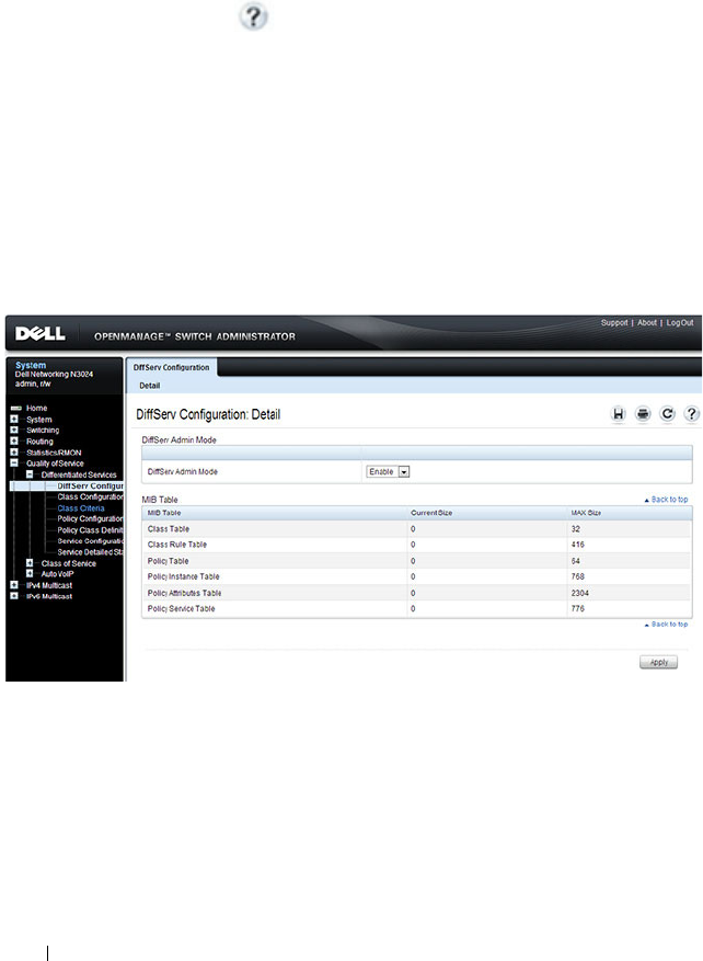
1288 Configuring Differentiated Services
Configuring DiffServ (Web)
This section provides information about the OpenManage Switch
Administrator pages for configuring and monitoring DiffServ features on a
Dell Networking N2000, N3000, and N4000 series switches. For details about
the fields on a page, click at the top of the page.
DiffServ Configuration
Use the
DiffServ Configuration page to display the DiffServ administrative
mode setting as well as the current and maximum number of rows in each of
the main DiffServ private MIB tables.
To display the
page, click Quality of Service
→
Differentiated Services
→
DiffServ Configuration in the navigation panel.
Figure 40-1. DiffServ Configuration
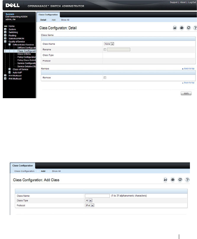
Configuring Differentiated Services 1289
Class Configuration
Use the
DiffServ Class Configuration page to add a new DiffServ class name,
or to rename or delete an existing class.
To display the
page, click Quality of Service
→
Differentiated Services
→
Class Configuration in the navigation panel.
Figure 40-2. DiffServ Class Configuration
Adding a DiffServ Class
To add a DiffServ class:
1
From the
DiffServ Class Configuration
page, click
Add
to display the
Add Class
page.
Figure 40-3. Add DiffServ Class
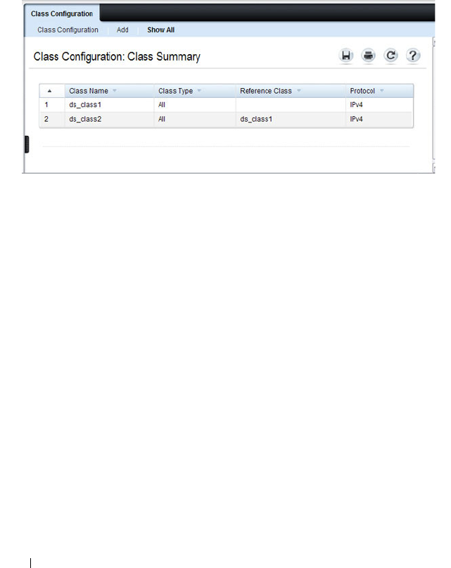
1290 Configuring Differentiated Services
2
Enter a name for the class and select the protocol to use for class match
criteria.
3
Click
Apply
to add the new class.
4
To view a summary of the classes configured on the switch, click
Show All
.
Figure 40-4. View DiffServ Class Summary
Class Criteria
Use the
DiffServ Class Criteria page to define the criteria to associate with a
DiffServ class. As packets are received, these DiffServ classes are used to
identify packets.
To display the
page, click Quality of Service
→
Differentiated Services
→
Class Criteria in the navigation panel.
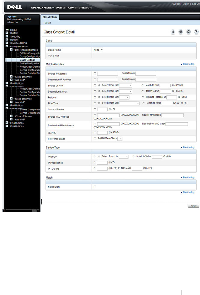
Configuring Differentiated Services 1291
Figure 40-5. DiffServ Class Criteria
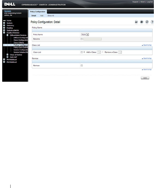
1292 Configuring Differentiated Services
Policy Configuration
Use the
DiffServ Policy Configuration page to associate a collection of
classes with one or more policy statements.
To display the
page, click Quality of Service
→
Differentiated Services
→
Policy Configuration in the navigation panel.
Figure 40-6. DiffServ Policy Configuration
Adding a New Policy Name
To add a policy:
1
From the
DiffServ Policy Configuration
page, click
Add
to display the
Add Policy
page.

Configuring Differentiated Services 1293
Figure 40-7. Add DiffServ Policy
2
Enter the new
Policy Name
.
3
Click
Apply
to save the new policy.
4
To view a summary of the policies configured on the switch, click
Show
All
.
Figure 40-8. View DiffServ Policies
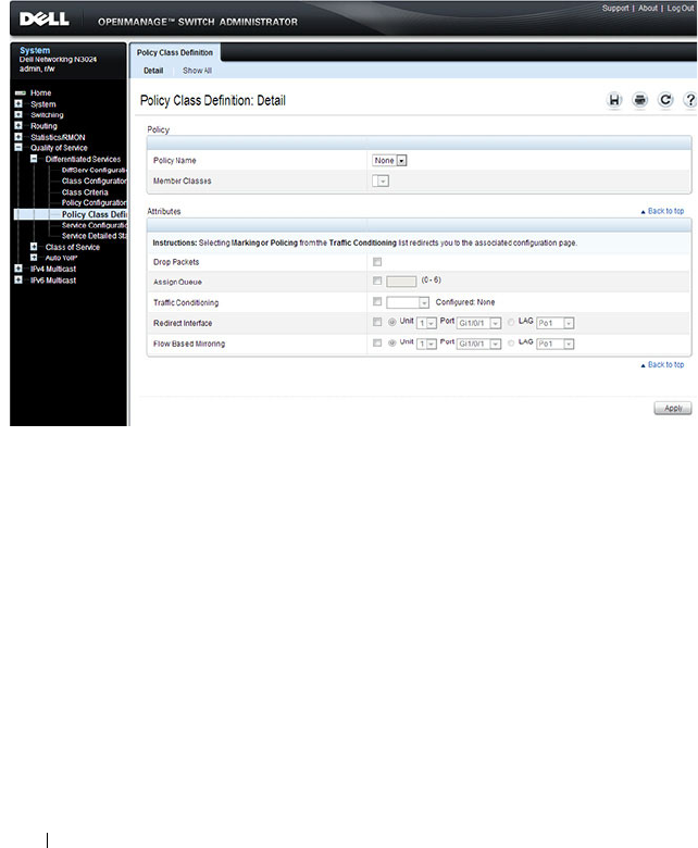
1294 Configuring Differentiated Services
Policy Class Definition
Use the
DiffServ Policy Class Definition page to associate a class to a policy,
and to define attributes for that policy-class instance.
To display the
page, click Quality of Service
→
Differentiated Services
→
Policy Class Definition in the navigation panel.
Figure 40-9. DiffServ Policy Class Definition
To view a summary of the policy attributes, click Show All.
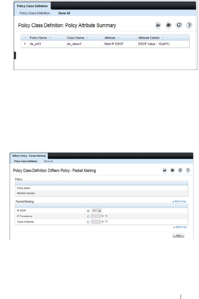
Configuring Differentiated Services 1295
Figure 40-10. Policy Class Definition
Packet Marking Traffic Condition
Follow these steps to have packets that match the class criteria for this policy
marked with a marked with either an IP DSCP, IP precedence, or CoS value:
1
Select Marking from the
Traffic Conditioning
drop-down menu on the
DiffServ Policy Class Definition
page.
The
Packet Marking
page displays.
Figure 40-11. Policy Class Definition - Attributes
2
Select
IP DSCP
,
IP Precedence
, or
Class of Service
to mark for this policy-
class.
3
Select or enter a value for this field.
4
Click
Apply
to define the policy-class.
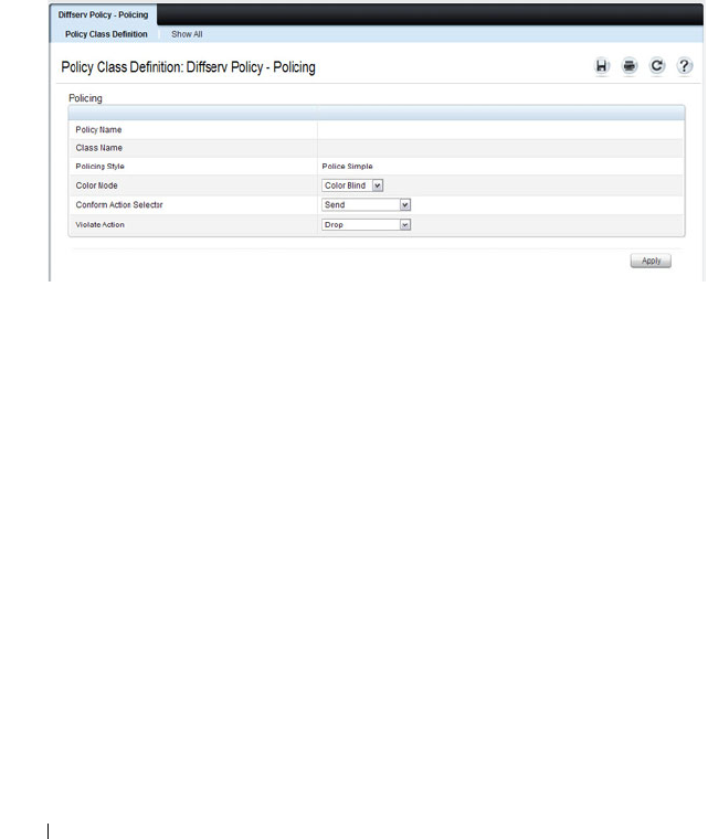
1296 Configuring Differentiated Services
Policing Traffic Condition
Follow these steps to perform policing on the packets that match this policy
class:
1
Select
Policing
from the
Traffic Conditioning
drop-down menu on the
DiffServ Policy Class Definition
page to display the
DiffServ Policy -
Policing
page.
Figure 40-12. Policy Class Definition - Policing
The
DiffServ Policy - Policing
page displays the
Policy Name
,
Class
Name
, and
Policing Style
.
Select a value for the following fields:
•
Color Mode
— The type of color policing used: Color Blind or Color
Aware.
•
Conform Action Selector
— The action taken on packets that are
considered conforming (below the police rate). Options are Send,
Drop, Mark CoS, Mark IP DSCP, Mark IP Precedence.
•
Violate Action
— The action taken on packets that are considered
non-conforming (above the police rate). Options are Send, Drop,
Mark CoS, Mark IP DSCP, Mark IP Precedence.
2
Click
Apply
.
The policy-class is defined, and the device is updated.
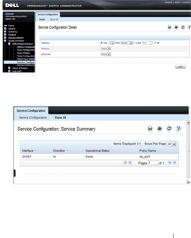
Configuring Differentiated Services 1297
Service Configuration
Use the
DiffServ Service Configuration page to activate a policy on a port.
To display the
page, click Quality of Service
→
Differentiated Services
→
Service Configuration in the navigation panel.
Figure 40-13. DiffServ Service Configuration
To view a summary of the services configured on the switch, click Show All.
Figure 40-14. DiffServ Service Summary
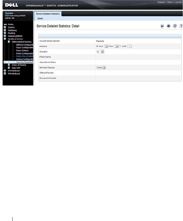
1298 Configuring Differentiated Services
Service Detailed Statistics
Use the
DiffServ Service Detailed Statistics page to display packet details for
a particular port and class.
To display the
page, click Quality of Service
→
Differentiated Services
→
Service Detailed Statistics in the navigation panel.
Figure 40-15. DiffServ Service Detailed Statistics
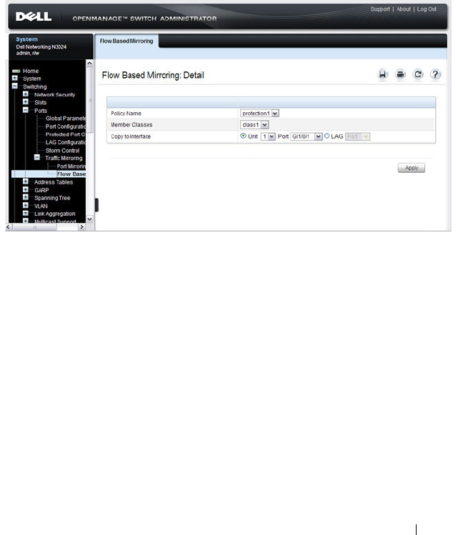
Configuring Differentiated Services 1299
Flow-Based Mirroring
Use the Flow-Based Mirroring page to create a mirroring session in which the
traffic that matches the specified policy and member class is mirrored to a
destination port.
To display the Flow-Based Mirroring page, click Switching
→
Ports
→
Traffic
Mirroring
→
Flow-Based Mirroring in the navigation panel.
Figure 40-16. Flow-Based Mirroring

1300 Configuring Differentiated Services
Configuring DiffServ (CLI)
This section provides information about the commands you use to configure
DiffServ settings on the switch. For more information about the commands,
see the
Dell Networking N2000, N3000, and N4000 Series Switches CLI
Reference Guide
at support.dell.com/manuals.
DiffServ Configuration (Global)
Beginning in Privileged Exec mode, use the following commands in to
configure the global DiffServ mode and view related settings.
DiffServ Class Configuration for IPv4
Beginning in Privileged Exec mode, use the following commands to configure
DiffServ classes for IPv4 and view related information.
CLI Command Description
configure Enter global configuration mode.
diffserv Set the DiffServ operational mode to active.
exit Exit to Privileged EXEC mode.
show diffserv Display the DiffServ general information, which
includes the current administrative mode setting as
well as the current and maximum number of
DiffServ components.
CLI Command Description
configure Enter global configuration mode.
class-map match-all
class-map-
name
Define a new DiffServ class and enter Class-Map
Configuration mode for the specified class.
NOTE: To enter Class-Map Configuration mode for a
class that has already been created, use the class-
map
class-map-name
command.
match any Configure a match condition for all the packets.
match class-map Add to the specified class definition the set of
match conditions defined for another class.

Configuring Differentiated Services 1301
match cos Add to the specified class definition a match
condition for the Class of Service value.
match destination-address mac Add to the specified class definition a match
condition based on the destination MAC address of
a packet.
match dstip Add to the specified class definition a match
condition based on the destination IP address of a
packet.
match dstl4port Add to the specified class definition a match
condition based on the destination layer 4 port of a
packet using a single keyword, or a numeric
notation.
match ethertype Add to the specified class definition a match
condition based on the value of the ethertype.
match ip dscp Add to the specified class definition a match
condition based on the value of the IP DiffServ
Code Point (DSCP) field in a packet.
match ip precedence Add to the specified class definition a match
condition based on the value of the IP.
match ip tos Add to the specified class definition a match
condition based on the value of the IP TOS field in
a packet.
match protocol Add to the specified class definition a match
condition based on the value of the IP Protocol field
in a packet using a single keyword notation or a
numeric value notation.
match secondary-cos Configure a match condition based on a secondary
COS value.
match secondary-vlan Configure a match condition based on a secondary
VLAN value.
match source-address mac Add to the specified class definition a match
condition based on the source MAC address of the
packet.
CLI Command Description

1302 Configuring Differentiated Services
DiffServ Class Configuration for IPv6
Beginning in Privileged Exec mode, use the following commands to configure
DiffServ classes for IPv6 and view related information.
match srcip Add to the specified class definition a match
condition based on the source IP address of a
packet.
match srcl4port Add to the specified class definition a match
condition based on the source layer 4 port of a
packet using a single keyword, a numeric notation,
or a numeric range notation.
match vlan Add to the specified class definition a match
condition based on the value of the layer 2 VLAN
Identifier field.
CLI Command Description
configure Enter global configuration mode.
class-map match-all
class-map-
name
ipv6
Define a new DiffServ class.
match any Configure a match condition for all the packets.
match class-map Add to the specified class definition the set of
match conditions defined for another class.
match dstip6 Add to the specified class definition a match
condition based on the destination IPv6 address of a
packet.
match dstl4port Add to the specified class definition a match
condition based on the destination layer 4 port of a
packet using a single keyword, or a numeric
notation.
match ip6flowlbl Add to the specified class definition a match
condition based on the IPv6 flow label of a packet.
match ip dscp Add to the specified class definition a match
condition based on the value of the IP DiffServ
Code Point (DSCP) field in a packet.
CLI Command Description

Configuring Differentiated Services 1303
DiffServ Policy Creation
Beginning in Privileged Exec mode, use the following commands to configure
DiffServ policies and view related information.
match protocol Add to the specified class definition a match
condition based on the value of the IP Protocol field
in a packet using a single keyword notation or a
numeric value notation.
match source-address mac Add to the specified class definition a match
condition based on the source MAC address of the
packet.
match srcip6 Add to the specified class definition a match
condition based on the source IPv6 address of a
packet.
match srcl4port Add to the specified class definition a match
condition based on the source layer 4 port of a
packet using a single keyword, a numeric notation,
or a numeric range notation.
CLI Command Description
configure Enter global configuration mode.
policy-map
policy-name
in Create a new DiffServ policy for ingress traffic and
enter Policy Map Configuration mode for the policy.
exit Exit to Privilege Exec mode.
show policy-map Displays all configuration information for the
specified policy.
show policy-map
interface
in Displays policy-oriented statistics information for
the specified interface.
CLI Command Description

1304 Configuring Differentiated Services
DiffServ Policy Attributes Configuration
Beginning in Privilege Exec mode, use the following commands to configure
policy attributes and view related information.
CLI Command Description
configure Enter global configuration mode.
policy-map
policy-map-name
Enter Policy Map Configuration mode for the
specified policy.
class
class-name
Create an instance of a class definition within the
specified policy for the purpose of defining
treatment of the traffic class through subsequent
policy attribute statements. Also enters Policy-
Class-Map Configuration mode for the policy-class-
map instance.
assign-queue
queue-id
Modify the queue ID (range: 0–6) to which the
associated traffic stream is assigned.
police-simple {
datarate
burstsize
conform-action
{drop | set-cos-transmit
cos
|
set-prectransmit
cos
| set-dscp-
transmit
dscpval
| transmit}
[violateaction {drop | set-cos-
transmit
cos
| set-prec-
transmit
cos
| set-dscp-
transmit
dscpval
| transmit}]}
Establish the traffic policing style for the specified
class. The simple form of the police command uses
a single data rate and burst size, resulting in two
outcomes: conform and nonconform.
•
datarate
— Data rate in kilobits per second (kbps).
(Range: 1–4294967295)
•
burstsize
— Burst size in Kbps (Range: 1–128)
•
conform action
— Indicates what happens when
the packet is conforming to the policing rule: it
could be dropped, it could have its COS modified,
it could have its IP precedence modified, or it
could have its DSCP modified. The same actions
are available for packets that do not conform to the
policing rule.
•
cos
— Class of Service value. (Range: 0–7)
•
dscpval
— DSCP value. (Range: 0–63 or a keyword
from this list,
af11
,
af12
,
af13
,
af21
,
af22
,
af23
,
af31
,
af32
,
af33
,
af41
,
af42
,
af43
,
be
,
cs0
,
cs1
,
cs2
,
cs3
,
cs4
,
cs5
,
cs6
,
cs7
,
ef
)

Configuring Differentiated Services 1305
conform-color
class-map-name
[exceed-color
class-map-name
]
Specify the color class for color-aware policing.
The action for the policy-class-map instance must
be set to police-simple before issuing the conform-
color command.
drop Specify that all packets for the associated traffic
stream are to be dropped at ingress.
mark cos
cos-value
Mark all packets for the associated traffic stream
with the specified class of service value (range: 0–7)
in the priority field of the 802.1p header.
mark ip-dscp
dscp-value
Mark all packets for the associated traffic stream
with the specified IP DSCP value.
mark ip-precedence
value
Mark all packets for the associated traffic stream
with the specified IP precedence value (range: 0–7).
mirror
interface
| redirect
interface
Use mirror to mirror all packets for the associated
traffic stream that matches the defined class to the
specified destination port or LAG.
Use redirect to specify that all incoming packets for
the associated traffic stream are redirected to the
specified destination port or LAG.
exit Exit to Policy-Map Config mode.
exit Exit to Global Config mode.
exit Exit to Privilege Exec mode.
show policy-map
policy-map-
name
Displays configuration information for the specified
policy.
CLI Command Description

1306 Configuring Differentiated Services
DiffServ Service Configuration
Beginning Privilege Exec mode, use the following commands to associate a
policy with an interface and view related information.
CLI Command Description
configure Enter Global Configuration mode.
service-policy {in | out}
policy-map-name
Attach a policy to an interface in the
inbound or outbound direction.
This command can be used in either
Global Configuration mode (for all
system interfaces) or Interface
Configuration mode (for a specific
interface).
exit Exit to Privilege Exec mode.
show diffserv service brief [in | out] Display all interfaces in the system to
which a DiffServ policy has been
attached.
show diffserv service interface
interface
{in | out}
Display policy service information for
the specified interface, where
interface
is
replaced by gigabitethernet
unit/slot/port
, tengigabitethernet
unit/slot/port
, or port-channel
port-
channel number
.
show service-policy {in | out} Display a summary of policy-oriented
statistics information for all interfaces.
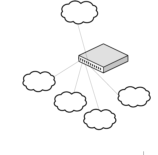
Configuring Differentiated Services 1307
DiffServ Configuration Examples
This section contains the following examples:
• Providing Subnets Equal Access to External Network
• DiffServ for VoIP
Providing Subnets Equal Access to External Network
This example shows how a network administrator can provide equal access to
the Internet (or other external network) to different departments within a
company. Each of four departments has its own Class B subnet that is
allocated 25% of the available bandwidth on the port accessing the Internet.
Figure 40-17. DiffServ Internet Access Example Network Diagram
Finance
Marketing
Test
Development
Internet
Layer 3 Switch
Port 1/0/5
Outbound
1/0/1
1/0/2
1/0/3 1/0/4
Source IP:
172.16.10.0
255.255.255.0
Source IP:
172.16.20.0
255.255.255.0
Source IP:
172.16.30.0
255.255.255.0
Source IP:
172.16.40.0
255.255.255.0

1308 Configuring Differentiated Services
The following commands show how to configure the DiffServ example
depicted in Figure 40-17.
1
Enable DiffServ operation for the switch.
console#config
console(config)#diffserv
2
Create a DiffServ class of type
all
for each of the departments, and name
them. Also, define the match criteria—Source IP address—for the new
classes.
console(config)#class-map match-all finance_dept
console(config-classmap)#match srcip 172.16.10.0 255.255.255.0
console(config-classmap)#exit
console(config)#class-map match-all marketing_dept
console(config-classmap)#match srcip 172.16.20.0 255.255.255.0
console(config-classmap)#exit
console(config)#class-map match-all test_dept
console(config-classmap)#match srcip 172.16.30.0 255.255.255.0
console(config-classmap)#exit
console(config)#class-map match-all development_dept
console(config-classmap)#match srcip 172.16.40.0 255.255.255.0
console(config-classmap)#exit
3
Create a DiffServ policy for inbound traffic named
internet_access,
adding
the previously created department classes as instances within this policy.
This policy uses the assign-queue attribute to put each department's
traffic on a different egress queue. This is how the DiffServ inbound policy
connects to the CoS queue settings established below.
console(config)#policy-map internet_access in
console(config-policy-map)#class finance_dept
console(config-policy-classmap)#assign-queue 1
console(config-policy-classmap)#exit
console(config-policy-map)#class marketing_dept
console(config-policy-classmap)#assign-queue 2
console(config-policy-classmap)#exit
console(config-policy-map)#class test_dept
console(config-policy-classmap)#assign-queue 3
console(config-policy-classmap)#exit

Configuring Differentiated Services 1309
console(config-policy-map)#class development_dept
console(config-policy-classmap)#assign-queue 4
console(config-policy-classmap)#exit
console(config-policy-map)#exit
4
Attach the defined policy to 10-Gigabit Ethernet interfaces 1/0/1 through
1/0/4 in the inbound direction
console(config)#interface tengigabitethernet 1/0/1
console(config-if-Te1/0/1)#service-policy in internet_access
console(config-if-Te1/0/1)#exit
console(config)#interface tengigabitethernet 1/0/2
console(config-if-Te1/0/2)#service-policy in internet_access
console(config-if-Te1/0/2)#exit
console(config)#interface tengigabitethernet 1/0/3
console(config-if-Te1/0/3)#service-policy in internet_access
console(config-if-Te1/0/3)#exit
console(config)#interface tengigabitethernet 1/0/4
console(config-if-Te1/0/4)#service-policy in internet_access
console(config-if-Te1/0/4)#exit
5
Set the CoS queue configuration for the (presumed) egress 10-Gigabit
Ethernet interface 1/0/1 such that each of queues 1, 2, 3 and 4 get a
minimum guaranteed bandwidth of 25%. All queues for this interface use
weighted round robin scheduling by default. The DiffServ inbound policy
designates that these queues are to be used for the departmental traffic
through the assign-queue attribute. It is presumed that the switch will
forward this traffic to 10-Gigabit Ethernet interface 1/0/1 based on a
normal destination address lookup for internet traffic.
console(config)#interface tengigabitethernet 1/0/5
console(config-if-
Te
1/0/5)#cos-queue min-bandwidth 0 25 25 25 25 0 0
console(config-if-Te1/0/5)#exit
console(config)#exit
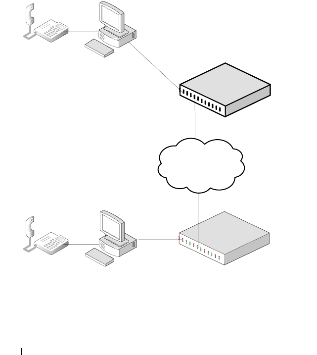
1310 Configuring Differentiated Services
DiffServ for VoIP
One of the most valuable uses of DiffServ is to support Voice over IP (VoIP).
VoIP traffic is inherently time-sensitive: for a network to provide acceptable
service, a guaranteed transmission rate is vital. This example shows one way
to provide the necessary quality of service: how to set up a class for UDP
traffic, have that traffic marked on the inbound side, and then expedite the
traffic on the outbound side. The configuration script is for Router 1 in the
accompanying diagram: a similar script should be applied to Router 2.
Figure 40-18. DiffServ VoIP Example Network Diagram
Internet
`
`
Layer 3 Switch
Operating as
Router 1
Layer 3 Switch
Operating as
Router 2
Port 1/0/2
Port 1/0/3

Configuring Differentiated Services 1311
The following commands show how to configure the DiffServ example
depicted in Figure 40-18.
1
Set queue 6 on all ports to use strict priority mode. This queue shall be
used for all VoIP packets. Activate DiffServ for the switch.
console#config
console(config)#cos-queue strict 6
console(config)#diffserv
2
Create a DiffServ classifier named
class_voip
and define a single match
criterion to detect UDP packets. The class type
match-all
indicates that all
match criteria defined for the class must be satisfied in order for a packet
to be considered a match.
console(config)#class-map match-all class_voip
console(config-classmap)#match protocol udp
console(config-classmap)#exit
3
Create a second DiffServ classifier named class_ef and define a single
match criterion to detect a DiffServ code point (DSCP) of EF (expedited
forwarding). This handles incoming traffic that was previously marked as
expedited elsewhere in the network.
console(config)#class-map match-all class_ef
console(config-classmap)#match ip dscp ef
console(config-classmap)#exit
4
Create a DiffServ policy for inbound traffic named pol_voip, then add the
previously created classes 'class_ef' and 'class_voip' as instances within this
policy. This policy handles incoming packets already marked with a DSCP
value of EF (per class_ef definition), or marks UDP packets (per the
class_voip definition) with a DSCP value of EF. In each case, the matching
packets are assigned internally to use queue 6 of the egress port to which
they are forwarded.
console(config)#policy-map pol_voip in
console(config-policy-map)#class class_ef
console(config-policy-classmap)#assign-queue 6
console(config-policy-classmap)#exit
console(config-policy-map)#class class_voip
console(config-policy-classmap)#mark ip-dscp ef
console(config-policy-classmap)#assign-queue 6

1312 Configuring Differentiated Services
console(config-policy-classmap)#exit
console(config-policy-map)#exit
5
Attach the defined policy to an inbound service interface.
console(config)#interface tengigabitethernet 1/0/1
console(config-if-Te1/0/1)#service-policy in
pol_voip
console(config-if-Te1/0/1)#exit
console(config)#exit

Configuring Class-of-Service 1313
41
Configuring Class-of-Service
This chapter describes how to configure the Class-of-Service (CoS) feature.
The CoS queueing feature lets you directly configure certain aspects of switch
queueing. This provides the desired QoS behavior for different types of
network traffic when the complexities of DiffServ are not required. The
priority of a packet arriving at an interface can be used to steer the packet to
the appropriate outbound CoS queue through a mapping table. CoS queue
characteristics that affect queue mapping, such as minimum guaranteed
bandwidth, transmission rate shaping, etc., are user-configurable at the queue
(or port) level.
The topics covered in this chapter include:
• CoS Overview
• Default CoS Values
• Configuring CoS (Web)
• Configuring CoS (CLI)
• CoS Configuration Example
CoS Overview
The CoS feature lets you give preferential treatment to certain types of traffic
over others. To set up this preferential treatment, you can configure the
ingress ports, the egress ports, and individual queues on the egress ports to
provide customization that suits your environment.
The level of service is determined by the egress port queue to which the
traffic is assigned. When traffic is queued for transmission, the rate at which
it is serviced depends on how the queue is configured and possibly the
amount of traffic present in other queues for that port.
Some traffic is classified for service (i.e., packet marking) before it arrives at
the switch. If you decide to use these classifications, you can map this traffic
to egress queues by setting up a CoS Mapping table.

1314 Configuring Class-of-Service
Each ingress port on the switch has a default priority value (set by configuring
VLAN Port Priority in the Switching sub-menu) that determines the egress
queue its traffic gets forwarded to. Packets that arrive without a VLAN user
priority, or packets from ports you’ve identified as “untrusted,” get forwarded
according to this default.
What Are Trusted and Untrusted Port Modes?
Ports can be configured in “trusted” mode or “untrusted” mode with respect
to ingress traffic.
Ports in Trusted Mode
When a port is configured in trusted mode, the system accepts at face value a
priority designation encoded within packets arriving on the port. You can
configure ports to trust priority designations based on one of the following
fields in the packet header:
• 802.1 Priority: values 0–7
• IP DSCP: values 0–63
A mapping table associates the designated field values in the incoming packet
headers with a traffic class priority (actually a CoS traffic queue).
Ports in Untrusted Mode
If you configure an ingress port in untrusted mode, the system ignores any
priority designations encoded in incoming packets, and instead sends the
packets to a traffic queue based on the ingress port’s default priority.
How Is Traffic Shaping Used on Egress Traffic?
For unit/slot/port interfaces, you can specify a traffic shaping rate for the port
(in Kbps) for egress traffic. The traffic shaping rate specifies an upper limit of
the transmission bandwidth used. Once the traffic shaping rate has been
reached, frames that exceeded the limit remain queued for transmission until
the next scheduling slot.

Configuring Class-of-Service 1315
How Are Traffic Queues Defined?
For each queue, you can specify:
• Minimum bandwidth guarantee—A percentage of the port’s maximum
negotiated bandwidth reserved for the queue. Unreserved bandwidth can
be utilized by lower-priority queues. If the sum of the minimum
bandwidth is 100%, then there is no unreserved bandwidth and no sharing
of bandwidth is possible.
• Scheduler type—strict/weighted:
– Strict priority scheduling gives an absolute priority based on CoS
queue number, with traffic in the highest numbered queue sent first,
then the next lowest numbered queue, and so on. Weighted queues
are serviced after all strict priority queues have been serviced.
– Weighted scheduling selects packets for transmission with a fixed
weighting equal to the CoS queue number plus one. The weighted
scheduler measures bandwidth based upon bytes vs. packet counts,
offering a better granularity of scheduling. For example, if CoS queues
0, 1, and 2 have an equal offered load toward a congested output port,
CoS queue 2 will receive 3/6 of the bandwidth, CoS queue 1 will
receive 2/6 of the bandwidth, and CoS queue 0 will receive 1/6 of the
bandwidth.
The minimum bandwidth setting can be used to override the strict priority
and weighted settings. The highest numbered strict priority queue will
receive no more bandwidth than 100 percent minus the sum of the minimum
bandwidths percentages assigned to the other queues. If used, it is
recommended that minimum bandwidth percentages only be high enough to
ensure a minimum level of service for any queue; i.e., the sum of the
minimum bandwidth percentages is a small fraction of 100%. This ensures
that the system can respond to bursts in traffic. Setting the minimum
bandwidth percentages such that they sum to 100% effectively sets the
scheduler such that sharing of bandwidth is disabled.
Which Queue Management Methods Are Supported?
The switch supports the following methods, configurable per-interface-
queue, for determining which packets are dropped when the queue is full:
• Taildrop—Any packet forwarded to a full queue is dropped regardless of its
priority.

1316 Configuring Class-of-Service
• Weighted Random Early Detection (WRED)—Drops packets queued for
transmission selectively based their drop precedence level. For each of four
drop precedence levels on each WRED-enabled interface queue, you can
configure the following parameters:
– Minimum Threshold: A percentage of the total queue size below
which no packets of the selected drop precedence level are dropped.
– Maximum Threshold: A percentage of the total queue size above
which all packets of the selected drop precedence level are dropped.
– Drop Probability: When the queue depth is between the minimum
and maximum thresholds, this value provides a scaling factor for
increasing the number of packets of the selected drop precedence level
that are dropped as the queue depth increases. The drop probability
supports configuration in the range of 0 to 10%, and the discrete
values 25%, 50%, and 75%. Values not listed are truncated to the next
lower value in hardware.
CoS Queue Usage
CoS queue 7 is reserved by the system and is not assignable. It is generally
recommended that the administrator utilize CoS queues 0 to 3, as CoS
queues 4-6 may be used by the system for other types of system traffic, for
example, routing protocol PDU handling.
Default CoS Values
Table 41-1 shows the global default values for CoS.
Table 41-1. CoS Global Defaults
Parameter Default Value
Trust Mode 802.1p
802.1p CoS value to queue mapping 802.1p CoS Queue
0, 3 1
1, 2 0
4, 5 2
6, 7 3

Configuring Class-of-Service 1317
IP DSCP value to queue mapping IP DSCP Queue
0–7, 24–31 1
8–23 0
32–47 2
48–63 3
Interface Shaping Rate 0 Kbps
Minimum Bandwidth 0%
Scheduler Type Weighted
Queue Management Type Taildrop
Drop Precedence Level 1
WRED Decay Exponent 9
WRED Minimum Threshold 40
WRED Maximum Threshold 100
WRED Drop Probability Scale 10
Table 41-1. CoS Global Defaults
Parameter Default Value
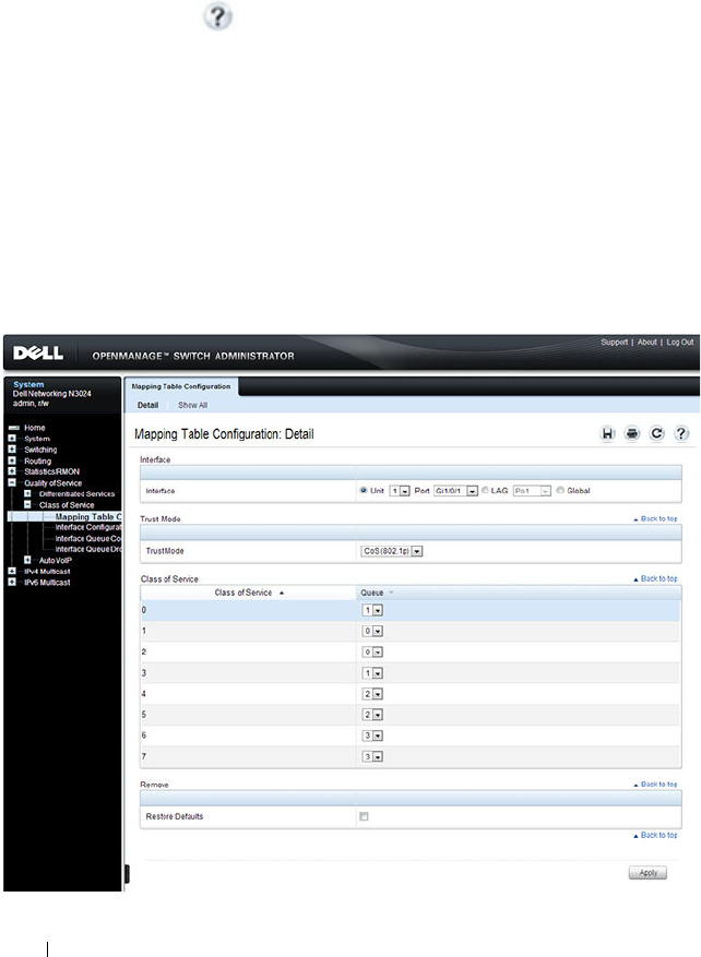
1318 Configuring Class-of-Service
Configuring CoS (Web)
This section provides information about the OpenManage Switch
Administrator pages for configuring and monitoring CoS features on a Dell
Networking N2000, N3000, and N4000 series switches. For details about the
fields on a page, click at the top of the page.
Mapping Table Configuration
Use the
Mapping Table Configuration page to define how class of service is
assigned to a packet.
To display the
page, click Quality of Service
→
Class of Service
→
Mapping
Table Configuration in the navigation panel. CoS(802.1P) is the default
mode, so this is the page that displays when Mapping Table Configuration is
selected from the Class of Service menu page.
Figure 41-1. Mapping Table Configuration
—
CoS (802.1P)
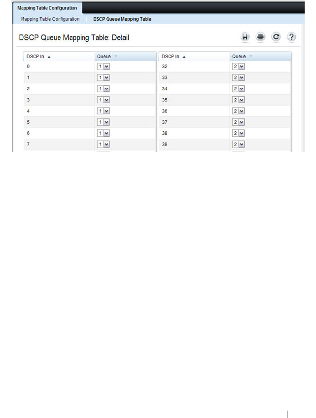
Configuring Class-of-Service 1319
To display the Queue Mapping Table for the selected Trust Mode, click the
Show All link at the top of the page. The following figure shows the queue
mapping table when CoS (802.1p) is selected as the Trust Mode.
Figure 41-2. DSCP Queue Mapping Table
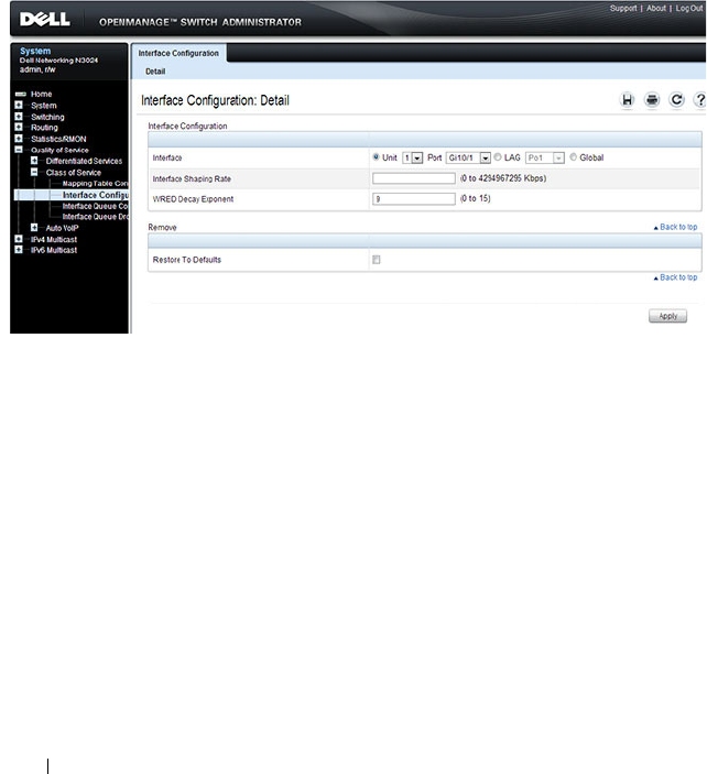
1320 Configuring Class-of-Service
Interface Configuration
Use the
Interface Configuration page to define the interface shaping rate for
egress packets on an interface and the decay exponent for WRED queues
defined on the interface.
Each interface CoS parameter can be configured globally or per-port. A global
configuration change is applied to all interfaces in the system.
To display the Interface Configuration page, click Quality of Service
→
Class
of Service
→
Interface Configuration in the navigation panel.
Figure 41-3. Interface Configuration
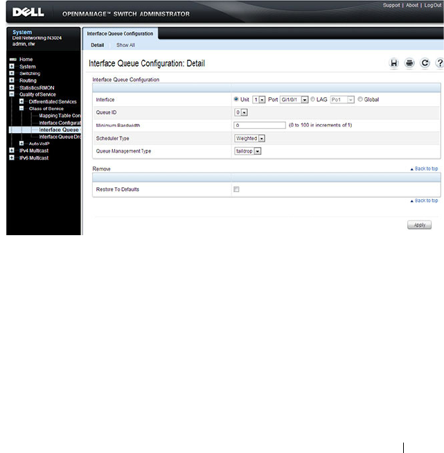
Configuring Class-of-Service 1321
Interface Queue Configuration
Use the
Interface Queue Configuration page to configure egress queues on
interfaces. The settings you configure control the amount of bandwidth the
queue uses, the scheduling method, and the queue management method.
The configuration process is simplified by allowing each CoS queue
parameter to be configured globally or per-port. A global configuration
change is applied to the same queue ID on all ports in the system.
To display the
Interface Queue Configuration page, click Quality of Service
→
Class of Service
→
Interface Queue Configuration in the navigation
panel.
Figure 41-4. Interface Queue Configuration
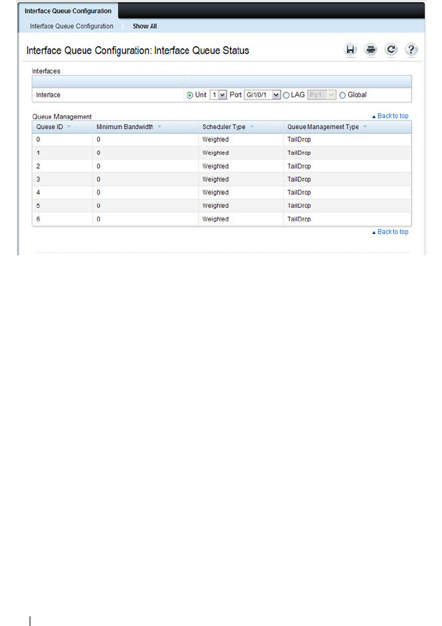
1322 Configuring Class-of-Service
To access the Interface Queue Status page, click the Show All link at the top
of the page.
Interface Queue Drop Precedence Configuration
Use the
Interface Queue Drop Precedence Configuration page to configure
thresholds and scaling values for each of four drop precedence levels on a
WRED-enabled interface queue. The settings you configure control the
minimum and maximum thresholds and a drop probability scaling factor for
the selected drop precedence level.
These parameters can be applied to each drop precedence level on a per-
interface-queue basis, or can be set globally for the same drop precedence
level and queue ID on all interfaces.
To display the
Interface Queue Drop Precedence Configuration page, click
Quality of Service
→
Class of Service
→
Interface Queue Drop Precedence
Configuration in the navigation panel.
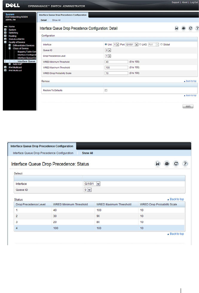
Configuring Class-of-Service 1323
Figure 41-5. Interface Queue Drop Precedence Configuration
To access the Interface Queue Drop Precedence Status page, click the Show
All link at the top of the page.

1324 Configuring Class-of-Service
Configuring CoS (CLI)
This section provides information about the commands you use to configure
CoS settings on the switch. For more information about the commands, see
the
Dell Networking N2000, N3000, and N4000 Series Switches CLI
Reference Guide
at support.dell.com/manuals.
Mapping Table Configuration
Beginning in Privileged Exec mode, use the following commands in to
configure the CoS mapping tables.
CLI Command Description
configure Enter Global Configuration mode.
interface
interface
Enter Interface Configuration mode, where
interface
is replaced by gigabitethernet
unit/slot/port
, tengigabitethernet
unit/slot/port
, or
port-channel
port-channel number
.
classofservice dotlp-mapping
priority
Map an 802.1p priority to an internal traffic class for
a switch. You can also use this command in Global
Configuration mode to configure the same
mappings on all interfaces.
classofservice trust {dot1p |
ip-dscp | untrusted}
Set the class of service trust mode of an interface.
exit Exit to Global Config mode.
exit Exit to Privilege Exec mode.
show classofservice dotlp-
mapping
Display the current Dot1p (802.1p) priority
mapping to internal traffic classes for a specific
interface.
show classofservice ip-dscp-
mapping
Display the current IP DSCP mapping to internal
traffic classes for a specific interface.
show classofservice trust Display the current trust mode setting for a specific
interface.

Configuring Class-of-Service 1325
CoS Interface Configuration Commands
Beginning in Privileged Exec mode, use the following commands in to
configure the traffic shaping and WRED exponent values for an interface.
Interface Queue Configuration
Beginning in Privileged Exec mode, use the following commands in to
configure and view CoS interface queue settings.
CLI Command Description
configure Enter Global Configuration mode.
interface
interface
Enter Interface Configuration mode, where
interface
is replaced by gigabitethernet
unit/slot/port
,
tengigabitethernet
unit/slot/port
, or port-channel
port-channel number
.
traffic-shape
bw
kbps Sets the upper limit on how much traffic can leave a
port. The
bw
variable represents the shaping
bandwidth value from 64 to 4294967295 kbps.
random-detect exponential-
weighting-constant
exponent
Configure the WRED decay exponent (range: 0–15)
for the interface. The weighting constant exponent
determines how much of the previous average queue
length sample is added to the current average queue
length. A value of 0 indicates that no weight is given
to the previous sample and only the instantaneous
rate is used. A value of 1 indicates that 1/2 of the
difference between the instantaneous value and the
previous value is added to the current value; a value of
2 implies that 1/4 of the difference is added, 3 implies
1/8 of the difference is added, etc.
CLI Command Description
configure Enter Global Configuration mode.
interface
interface
Enter Interface Configuration mode, where
interface
is
replaced by gigabitethernet
unit/slot/port
,
tengigabitethernet
unit/slot/port
., or port-channel
port-
channel number
.

1326 Configuring Class-of-Service
cos-queue min-bandwidth
bw
Specify the minimum transmission bandwidth (range:
0-100% in 1% increments) for each interface queue.
cos-queue strict
queue-id
Activate the strict priority scheduler mode for each
specified queue. The
queue-id
value ranges from 0 to 6.
cos-queue random-detect
queue-id
Set the queue management type for the specified
queue to WRED. The no version of this command
resets the value to taildrop.
exit Exit to Global Config mode.
exit Exit to Privilege Exec mode.
show interfaces cos-queue Display the class-of-service queue configuration for a
specified interface or all interfaces.
CLI Command Description

Configuring Class-of-Service 1327
Configuring Interface Queue Drop Probability
Beginning in Privileged Exec mode, use the following commands in to
configure characteristics of the drop probability and view related settings. The
drop probability supports configuration in the range of 0 to 10%, and the
discrete values 25%, 50%, and 75%. Values not listed are truncated to the next
lower value in hardware.
CLI Command Description
configure Enter Global Configuration mode.
interface
interface
Enter Interface Configuration mode, where
interface
is replaced by gigabitethernet
unit/slot/port
, tengigabitethernet
unit/slot/port
, or
port-channel
port-channel number
.
random-detect queue-parms
queue-id
[
queue-id
...] min-
thresh
min1 min2 min3 min4
max-thresh
max1 max2 max3
max4
drop-prob
prob1 prob2
prob3 prob4
Configure the maximum and minimum thresholds
for one or more queue IDs on a WRED-enabled
interface queue.
You can also use this command in Global
Configuration mode to configure the same
parameters for one or more queues on all interfaces.
exit Exit to Global Config mode.
exit Exit to Privilege Exec mode.
show interfaces random-detect Display WRED parameters for an interface or all
interfaces.

1328 Configuring Class-of-Service
CoS Configuration Example
Figure 41-6 illustrates the network operation as it relates to CoS mapping and
queue configuration.
Four packets arrive at the ingress port te1/0/10 in the order A, B, C, and D.
port te1/0/10 is configured to trust the 802.1p field of the packet, which serves
to direct packets A, B, and D to their respective queues on the egress port.
These three packets utilize the 802.1p to CoS Mapping Table for port
te1/0/10.
In this example, the 802.1p user priority 3 is configured to send the packet to
queue 5 instead of the default queue 3. Since packet C does not contain a
VLAN tag, the 802.1p user priority does not exist, so port te1/0/10 relies on its
default port priority (2) to direct packet C to egress queue 1.
Figure 41-6. CoS Mapping and Queue Configuration

Configuring Class-of-Service 1329
Continuing this example, the egress port te1/0/8 is configured for strict
priority on queue 6, and a weighted scheduling scheme is configured for
queues 5-0. Assuming queue 5 has a higher minimum bandwidth than queue
1 (relative bandwidth values are shown as a percentage, with 0% indicating
the bandwidth is not guaranteed), the queue service order is 6 followed by 5
followed by 1. Assuming each queue transmits all packets shown in the
diagram, the packet transmission order as seen on the network out of port
te1/0/8 is B, A, D, C. Thus, packet B, with its strict priority scheduling, is
transmitted ahead of the other packets at the egress port.
The following commands configure port 10 (ingress interface) and port 8
(egress interface).
1
Configure the Trust mode for port 10.
console#config
console(config)#interface tengigabitethernet
1/0/10
console(config-if-Te1/0/10)#classofservice trust
dot1p
2
For port 10, configure t
he 802.1p user priority 3
to send the packet to
queue 5 instead of the default queue (queue 3).
console(config-if-Te1/0/10)#classofservice dot1p-
mapping 3 5
3
For port 10, specify that untagged VLAN packets should have a default
priority of 2.
console(config-if-Te1/0/10)#vlan priority 2
console(config-if-Te1/0/10)#exit
4
For port 8, the egress port, configure a weighted scheduling scheme for
queues 5-0.
console(config)#interface tengigabitethernet 1/0/8
console(config-if-Te1/0/8)#cos-queue min-
bandwidth 0 0 5 5 10 20 40
5
Configure port 8 to have strict priority on queue 6:
console(config-if-Te1/0/8)#cos-queue strict 6
To configure the CoS queues for lossless traffic when transporting iSCSI
traffic, set the lossless traffic class to have a one-to-one mapping with the
priority value. The following example illustrates how to change the dot1p

1330 Configuring Class-of-Service
mapping from the switch defaults to support lossless1 transport of frames on
CoS queue 4, with a 50% minimum bandwidth guarantee. Lossless traffic
classes generally use the default WRR scheduling mode as opposed to strict
priority, to avoid starving other traffic. For example, the following commands
assign user priority 4 to CoS queue 4 and reserve 50% of the scheduler
bandwidth to CoS queue 4. This implies that, when the switch is congested,
the scehduler will service CoS queue 4 fifty percent of the time to the
exclusion of all other CoS queues, including higher-priority CoS queues.
classofservice dot1p-mapping 4 4
cos-queue min-bandwidth 0 0 0 0 50 0 0
1. Lossless behavior is guaranteed only when configured in conjunction with a conges-
tion control mechanism such as PFC.

Configuring Auto VoIP 1331
42
Configuring Auto VoIP
Voice over Internet Protocol (VoIP) allows you to make telephone calls using a
computer network over a data network like the Internet. With the increased
prominence of delay-sensitive applications (voice, video, and other
multimedia applications) deployed in networks today, proper QoS
configuration will ensure high-quality application performance. The Auto
VoIP feature is intended to provide an easy classification mechanism for voice
packets so that they can be prioritized above data packets in order to provide
better QoS. Because Auto VoIP is limited to 16 sessions, Voice VLAN is the
preferred solution for enterprises wishing to deploy a large scale voice service.
The topics covered in this chapter include:
• Auto VoIP Overview
• Default Auto VoIP Values
• Configuring Auto VoIP (Web)
• Configuring Auto VoIP (CLI)
Auto VoIP Overview
The Auto VoIP feature explicitly matches VoIP streams in Ethernet switches
and provides them with a better class of service than ordinary traffic. If you
enable the Auto VoIP feature on an interface, the interface scans incoming
traffic for the following call-control protocols:
• Session Initiation Protocol (SIP)
•H.323
• Skinny Client Control Protocol (SCCP)
When a call-control protocol is detected the switch assigns the traffic in that
session to the highest CoS queue, which is generally used for time-sensitive
traffic.
1332 Configuring Auto VoIP
Auto-VoIP is limited to 16 sessions and makes use of the switch CPU to
classify traffic. It is preferable to use the Voice VLAN feature in larger
enterprise environments as it uses the switching silicon to classify voice traffic
onto a VLAN.
How Does Auto-VoIP Use ACLs?
Auto-VoIP borrows ACL lists from the global system pool. ACL lists allocated
by Auto-VoIP reduce the total number of ACLs available for use by the
network operator. Enabling Auto-VoIP uses one ACL list to monitor for VoIP
sessions. Each monitored VoIP session utilizes two rules from an additional
ACL list. This means that the maximum number of ACL lists allocated by
Auto-VoIP is two.
Default Auto VoIP Values
Table 42-1 shows the global default value for Auto VoIP.
Table 42-1. Auto VoIP Global Defaults
Parameter Default Value
Auto VoIP Disabled
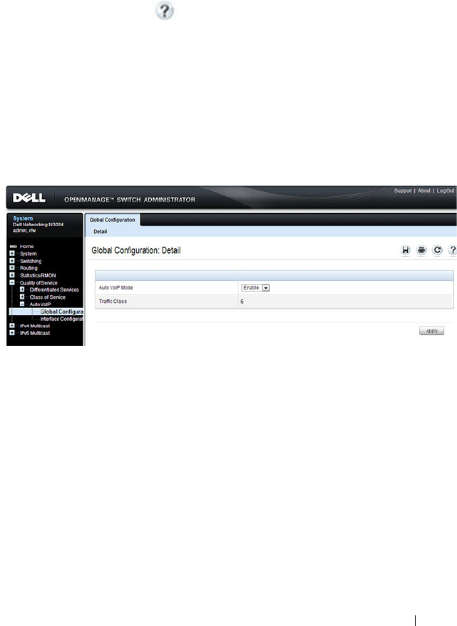
Configuring Auto VoIP 1333
Configuring Auto VoIP (Web)
This section provides information about the OpenManage Switch
Administrator pages for configuring and monitoring Auto VoIP features on a
Dell Networking N2000, N3000, and N4000 series switches. For details about
the fields on a page, click at the top of the page.
Auto VoIP Global Configuration
Use the
Global Configuration page to enable or disable Auto VoIP on all
interfaces.
To display the Auto VoIP Global Configuration page, click Quality of Service
→
Auto VoIP
→
Global Configuration in the navigation menu.
Figure 42-1. Auto VoIP Global Configuration
Auto VoIP Interface Configuration
Use the
Interface Configuration page to enable or disable Auto VoIP on a
particular interface.
To display the Interface Configuration page, click Quality of Service
→
Auto
VoIP
→
Interface Configuration in the navigation menu.
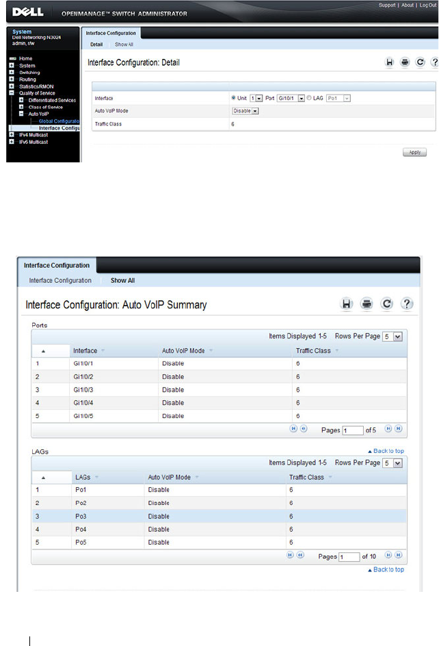
1334 Configuring Auto VoIP
Figure 42-2. Auto VoIP Interface Configuration
To display summary Auto VoIP configuration information for all interfaces,
click the Show All link at the top of the page.
Figure 42-3. Auto VoIP

Configuring Auto VoIP 1335
Configuring Auto VoIP (CLI)
This section provides information about the commands you use to configure
Auto VoIP settings on the switch. For more information about the
commands, see the
Dell Networking N2000, N3000, and N4000 Series
Switches CLI Reference Guide
at support.dell.com/manuals.
Mapping Table Configuration
Beginning in Privileged Exec mode, use the following commands in to enable
Auto VoIP and view its configuration.
CLI Command Description
configure Enter Global Configuration mode.
switchport voice detect auto Enable the VoIP Profile on all the interfaces of the
switch. You can also enter Interface Configuration
mode and use the same command to enable it on a
specific interface.
exit Exit to Global Configuration Exec mode.
exit Exit to Privilege Exec mode.
show switchport voice Show the status of Auto-VoIP on all interfaces or on
an interface, if one is specified.

1336 Configuring Auto VoIP

Managing IPv4 and IPv6 Multicast 1337
43
Managing IPv4 and IPv6 Multicast
This chapter describes how to configure and monitor layer 3 multicast
features for IPv4 and IPv6, including global IP and IPv6 multicast features as
well as multicast protocols, including IGMP, DVMRP, and PIM for IPv4 and
MLD and PIM for IPv6.
The topics covered in this chapter include:
L3 Multicast Overview
IP Multicasting enables a network host (or multiple hosts) to send an IP
datagram to multiple destinations simultaneously. The initiating host sends
each multicast datagram only once to a destination multicast group address,
and multicast routers forward the datagram only to hosts who are members of
the multicast group. Multicast enables efficient use of network bandwidth
because each multicast datagram needs to be transmitted only once on each
network link, regardless of the number of destination hosts. Multicasting
contrasts with IP unicasting, which sends a separate datagram to each
NOTE: This feature not available on N2000 switches.
• L3 Multicast Overview
• Default L3 Multicast Values
• Configuring General IPv4
Multicast Features (Web)
• Configuring IPv6 Multicast
Features (Web)
• Configuring IGMP and
IGMP Proxy (Web)
• Configuring MLD and MLD
Proxy (Web)
• Configuring PIM for IPv4 and
IPv6 (Web)
• Configuring DVMRP (Web)
• Configuring L3 Multicast
Features (CLI)
• L3 Multicast Configuration
Examples

1338 Managing IPv4 and IPv6 Multicast
recipient host. The IP routing protocols can route multicast traffic, but the IP
multicast protocols handle the multicast traffic more efficiently with better
use of network bandwidth.
Applications that often send multicast traffic include video or audio
conferencing, Whiteboard tools, stock distribution tickers, and IP-based
television (IP/TV).
What Is IP Multicast Traffic?
IP multicast traffic is traffic that is destined to a host group. Host groups are
identified by class D IP addresses, which range from 224.0.0.0 to
239.255.255.255. When a packet with a broadcast or multicast destination IP
address is received, the switch will forward a copy into each of the remaining
network segments in accordance with the IEEE MAC Bridge standard.
Eventually, the packet is made accessible to all nodes connected to the
network.
This approach works well for broadcast packets that are intended to be seen or
processed by all connected nodes. In the case of multicast packets, however,
this approach could lead to less efficient use of network bandwidth,
particularly when the packet is intended for only a small number of nodes.
Packets will be flooded into network segments where no node has any interest
in receiving the packet. The L3 multicast features on the switch help to
ensure that only the hosts in the multicast group receive the multicast traffic
for that group.
Multicast applications send one copy of a packet, and address it to a group of
receivers (Multicast Group Address) rather than to a single receiver (unicast
address). Multicast depends on the network to forward the packets to only
those networks and hosts that need to receive them.

Managing IPv4 and IPv6 Multicast 1339
What Multicast Protocols Does the Switch Support?
Multicast protocols are used to deliver multicast packets from one source to
multiple receivers. Table 43-1 summarizes the multicast protocols that the
switch supports.
What Are the Multicast Protocol Roles?
Hosts must have a way to identify their interest in joining any particular
multicast group, and routers must have a way to collect and maintain group
memberships. These functions are handled by the IGMP protocol in IPv4. In
IPv6, multicast routers use the Multicast Listener Discover (MLD) protocol
to maintain group membership information.
Multicast routers must also be able to construct a multicast distribution tree
that enables forwarding multicast datagrams only on the links that are
required to reach a destination group member. Protocols such as DVMRP, and
PIM handle this function.
IGMP and MLD are multicast group discovery protocols that are used
between the clients and the local multicast router. PIM-SM, PIM-DM, and
DVMRP are multicast routing protocols that are used across different
subnets, usually between the local multicast router and remote multicast
router.
Table 43-1. Multicast Protocol Support Summary
Protocol IPv4 or IPv6 For Communication Between
IGMP IPv4 Host-to-L3 switch/router
IGMP Proxy IPv4 Host-to-L3 switch/router
MLD IPv6 Host-to-L3 switch/router
MLD Proxy IPv6 Host-to-L3 switch/router
PIM-SM IPv4 and IPv6 L3-switch/router-to-L3 switch/router
PIM-DM IPv4 and IPv6 L3-switch/router-to-L3 switch/router
DVMRP IPv4 L3-switch/router-to-L3 switch/router

1340 Managing IPv4 and IPv6 Multicast
When Is L3 Multicast Required on the Switch?
Use the IPv4/IPv6 multicast feature on Dell Networking series switches to
route multicast traffic between VLANs on the switch. If all hosts connected
to the switch are on the same subnet, there is no need to configure the
IP/IPv6 multicast feature. If the switch does not require L3 routing, you can
use IGMP snooping or MLD snooping to manage port-based multicast group
membership. For more information, see "What Is IGMP Snooping?" on
page 805 and "What Is MLD Snooping?" on page 807. If the local network
does not have a multicast router, you can configure the switch to act as the
IGMP querier. For more information, see "IGMP Snooping Querier" on
page 807.
If the switch is configured as a L3 switch and handles inter-VLAN routing
through static routes, OSPF, or RIP, and multicast traffic is transmitted
within the network, enabling and configuring L3 multicast routing on the
switch is recommended.
Multicast packets locally routed into a VLAN by the router are flooded to all
ports in the VLAN. Multicast packets ingressing a port that is a member of a
routed VLAN are flooded to all ports in the VLAN other than the receiving
port. It is strongly recommended that multicast routed VLANs only contain
two ports, one on each connecting switch. A VLAN carrying multicast traffic
should never traverse a multicast router, as ingress multicast traffic is L2-
switched across the VLAN, defeating the purpose of the multicast router.
Determining Which Multicast Protocols to Enable
IGMP is required on any multicast router that serves IPv4 hosts. IGMP is not
required on inter-router links. MLD is required on any router that serves IPv6
hosts. MLD is not required on inter-router links. PIM-DM, PIM-SM, and
DVMRP are multicast routing protocols that help determine the best route
for IP (PIM and DVMRP) and IPv6 (PIM) multicast traffic.
IGMP is automatically enabled whenever an IPv4 multicast routing protocol
is enabled that requires it, i.e., PIM-SM, PIM-DM, and DVMRP via the CLI.
Likewise, MLD is automatically enabled whenever an IPv6 multicast routing
protocol is enabled that requires it (PIM-SM and PIM-DM) via the CLI.
IGMP and MLD may not be separately enabled or disabled via the CLI. They
may be separately enabled/disabled via the web.

Managing IPv4 and IPv6 Multicast 1341
For more information about when to use PIM-DM, see "Using PIM-DM as
the Multicast Routing Protocol" on page 1352. For more information about
when to use PIM-SM, see "Using PIM-SM as the Multicast Routing Protocol"
on page 1343. For more information about when to configure DVMRP, see
"Using DVMRP as the Multicast Routing Protocol" on page 1354. Unless
specifically required, IGMP/MLD snooping should be disabled on L3
multicast routers.
What Is the Multicast Routing Table?
Multicast capable/enabled routers forward multicast packets based on the
routes in the Multicast Routing Information Base (MRIB). These routes are
created in the MRIB during the process of building multicast distribution
trees by the Multicast Protocols running on the router. Different IP Multicast
routing protocols use different techniques to construct these multicast
distribution trees.
What Is IGMP?
The Internet Group Management Protocol (IGMP) is used by IPv4 systems
(hosts, L3 switches, and routers) to report their IP multicast group
memberships to any neighboring multicast routers. The Dell Networking
N2000, N3000, and N4000 series switches performs the multicast router role
of the IGMP protocol, which means it collects the membership information
needed by the active multicast routing protocol. IGMP is automatically
enabled when PIM or DVMRP are enabled via the CLI.
The Dell Networking N2000, N3000, and N4000 series switches also supports
IGMP Version 3. Version 3 adds support for source filtering, which is the
ability for a system to report interest in receiving packets only from specific
source addresses, as required to support Source-Specific Multicast [SSM], or
from all but specific source addresses, sent to a particular multicast address.
Version 3 is designed to be interoperable with Versions 1 and 2.
Understanding IGMP Proxy
IGMP proxy enables a multicast router to learn multicast group membership
information and forward multicast packets based upon the group
membership information. The IGMP Proxy is capable of functioning only in
certain topologies that do not require Multicast Routing Protocols (i.e.,

1342 Managing IPv4 and IPv6 Multicast
DVMRP, PIM-DM, and PIM-SM) and have a tree-like topology, as there is no
support for features like reverse path forwarding (RPF) to correct packet route
loops.
The proxy contains many downstream interfaces and a unique upstream
interface explicitly configured. It performs the host side of the IGMP protocol
on its upstream interface and the router side of the IGMP protocol on its
downstream interfaces.
The IGMP proxy offers a mechanism for multicast forwarding based only on
IGMP membership information. The router must decide about forwarding
packets on each of its interfaces based on the IGMP membership
information. The proxy creates the forwarding entries based on the
membership information and adds it to the multicast forwarding cache
(MFC) in order not to make the forwarding decision for subsequent multicast
packets with same combination of source and group.
What Is MLD?
Multicast Listener Discovery (MLD) protocol enables IPv6 routers to
discover the presence of multicast listeners, the hosts that wish to receive the
multicast data packets, on its directly-attached interfaces. The protocol
specifically discovers which multicast addresses are of interest to its
neighboring nodes and provides this information to the active multicast
routing protocol that makes decisions on the flow of multicast data packets.
MLD is automatically enabled whenever IPv6 PIM is enabled on IPv6
interfaces via the CLI.
The Multicast router sends General Queries periodically to request multicast
address listeners information from systems on an attached network. These
queries are used to build and refresh the multicast address listener state on
attached networks. Multicast listeners respond to these queries by reporting
their multicast addresses listener state and their desired set of sources with
Current-State Multicast address Records in the MLD2 Membership Reports.
The Multicast router also processes unsolicited Filter-Mode-Change records
and Source-List-Change Records from systems that want to indicate interest
in receiving or not receiving traffic from particular sources.
The Dell Networking implementation of MLD v2 supports the multicast
router portion of the protocol (i.e., not the listener portion). It is backward-
compatible with MLD v1.

Managing IPv4 and IPv6 Multicast 1343
What Is PIM?
The Protocol Independent Multicast protocol is a simple, protocol-
independent multicast routing protocol. PIM uses an existing unicast routing
table and a Join/Prune/Graft mechanism to build a tree. Dell Networking
series switches support two types of PIM: sparse mode (PIM-SM) and dense
mode (PIM-DM).
PIM-SM is most effective in networks with a sparse population of multicast
receivers. In contrast, PIM-DM is most effective in networks with densely
populated multicast receivers. In other words, PIM-DM can be used if the
majority of network hosts request to receive a multicast stream, while PIM-
SM might be a better choice in networks in which a small percentage of
network hosts, located throughout the network, wish to receive the multicast
stream.
Using
PIM-SM as the Multicast Routing Protocol
PIM-SM is used to efficiently route multicast traffic to multicast groups that
may span wide area networks and where bandwidth is constrained. PIM-SM
uses shared trees by default and implements source-based trees for efficiency.
PIM-SM assumes that no hosts want the multicast traffic unless they
specifically ask for it. It initially creates a shared distribution tree centered on
a defined “rendezvous point” (RP) through which source traffic is relayed to
the ultimate receiver. Multicast traffic sources first send the multicast data to
the RP, which in turn sends the data down the shared tree to the receivers.
Shared trees centered on an RP do not necessarily provide the shortest or
most optimal path. In such cases, a Dell Networking PIM-SM router adjacent
to the host switches to the shortest path upon seeing the very first multicast
data packet.
Many IP multicast applications, such as those that handle real-time
dissemination of financial information, require high performance. Multicast
group membership management (IGMP), unicast routing protocols (OSPF,
RIP), and multicast routing protocols are all required to enable end-to-end
multicast capabilities. The RP is a critical function for PIM-SM deployments.
RP redundancy is always recommended. In a shared-tree model, multicast
traffic from the multicast source is routed via the RP. If the RP goes down, the
multicast receivers do not receive traffic until the RP comes up again. In
general, more than one RP is configured (for a group range) to provide RP
redundancy. The PIM-SM router acting as a BSR advertises the list of
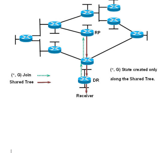
1344 Managing IPv4 and IPv6 Multicast
candidate RPs to all the PIM routers in the network. Each PIM router then
runs the RP selection algorithm to determine an RP for the given group
range. All the interested PIMSM routers then initiate re-reception of traffic
through this new RP, and the multicast traffic is rerouted via the new RP. This
is to provide high availability to the multicast applications and help ensure
that the multicast traffic is recovered quickly in such scenarios.
PIM-SM Protocol Operation
This section describes the workings of PIM-SM protocol per RFC 4601. The
protocol operates essentially in three phases, as explained in the following
sections.
Phase-1: RP Tree
Figure 43-1. PIM-SM Shared Tree Join
• In this example, an active receiver (attached to leaf router at the bottom of
the drawing) has joined multicast group “G”.
• The leaf router (labeled DR above) knows the IP address of the
Rendezvous Point (RP) for group G and sends a (*, G) Join for this group
towards the RP.
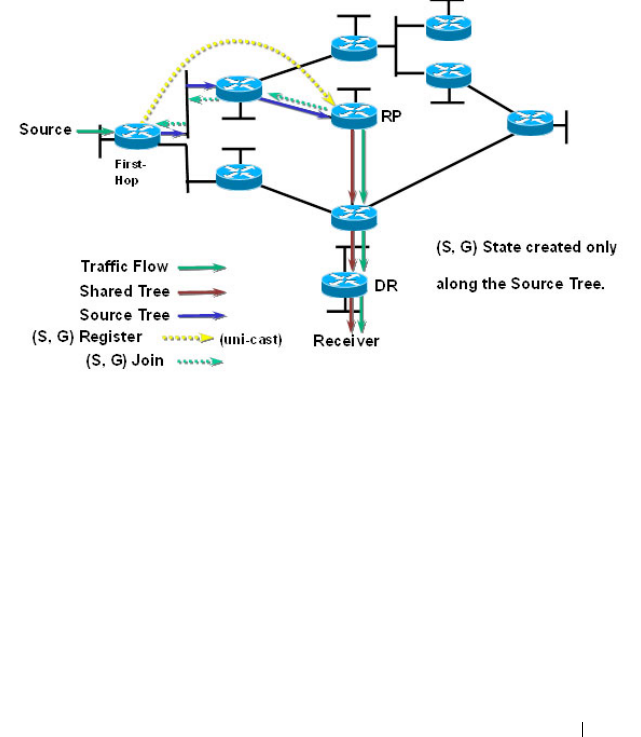
Managing IPv4 and IPv6 Multicast 1345
• This (*, G) Join travels hop-by-hop to the RP, building a branch of the
Shared Tree that extends from the RP to the last-hop router directly
connected to the receiver.
• At this point, group “G” traffic can flow down the Shared Tree to the
receiver.
Phase-2: Register Stop
Figure 43-2. PIM-SM Sender Registration—Part1
• As soon as an active source for group G sends a packet, the designated
router (DR) that is attached to this source is responsible for “Registering”
this source with the RP and requesting the RP to build a tree back to that
router.
• To do this, the source router encapsulates the multicast data from the
source in a special PIM-SM message, called the Register message, and
unicasts that data to the RP.
• When the RP receives the Register message, it does two things:
– It de-encapsulates the multicast data packet inside of the Register
message and forwards it down the Shared Tree.
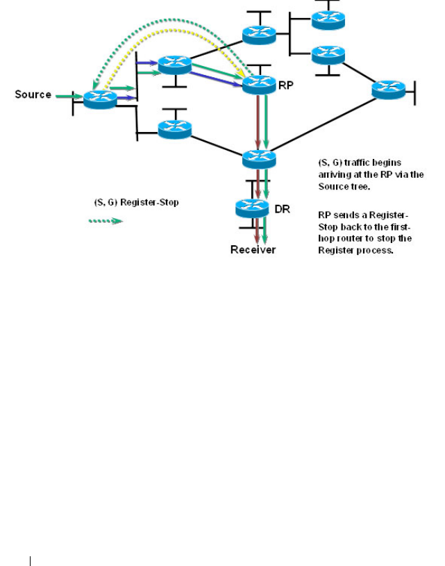
1346 Managing IPv4 and IPv6 Multicast
– The RP sends a source group (S, G) Join back towards the source to
create a branch of an (S, G) Shortest-Path Tree (SPT). This results in
the (S, G) state being created in the entire router path along the SPT,
including the RP.
Figure 43-3. PIM-SM Sender Registration—Part 2
• As soon as the SPT is built from the Source router to the RP, multicast
traffic begins to flow unencapsulated from source S to the RP.
• Once this is complete, the RP Router will send a “Register Stop” message
to the first-hop router to tell it to stop sending the encapsulated data to
the RP.
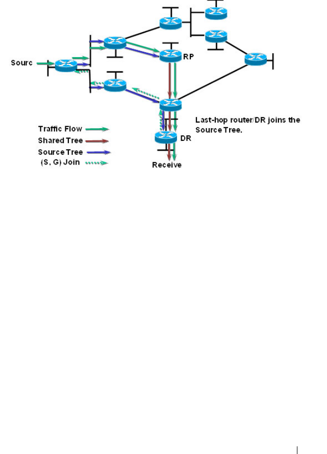
Managing IPv4 and IPv6 Multicast 1347
Phase 3: Shortest Path Tree
Figure 43-4. PIM-SM SPT—Part 1
• PIM-SM has the capability for last-hop routers (i.e., routers with directly
connected group members) to switch to the Shortest-Path Tree and bypass
the RP. This switchover is based upon an implementation-specific function
called SwitchToSptDesired(S,G) in the standard and generally takes a
number of seconds to switch to the SPT.
• In the above example, the last-hop router (at the bottom of the drawing)
sends an (S, G) Join message toward the source to join the SPT and bypass
the RP.
• This (S, G) Join messages travels hop-by-hop to the first-hop router (i.e.,
the router connected directly to the source), thereby creating another
branch of the SPT. This also creates (S, G) state in all the routers along
this branch of the SPT.
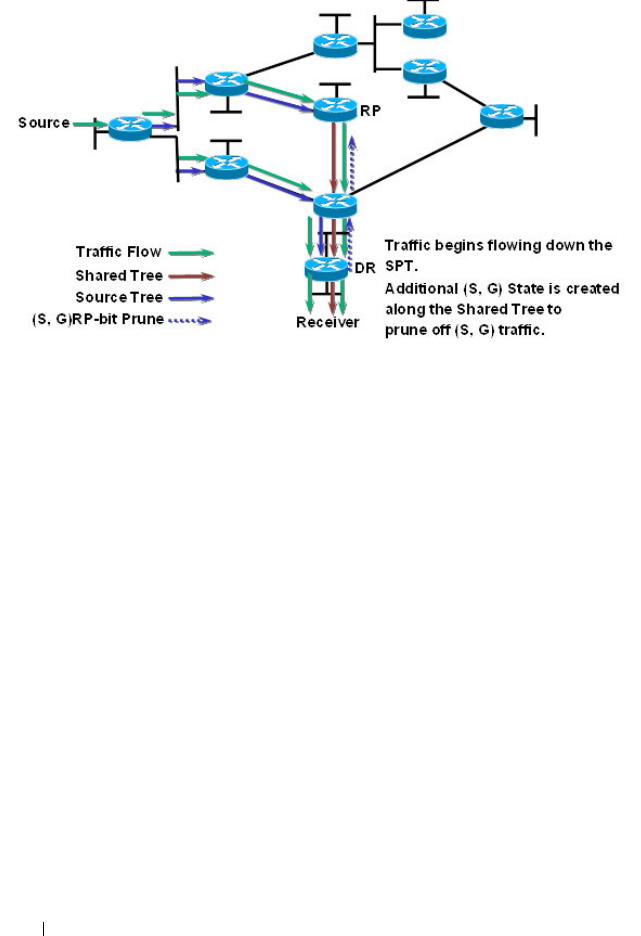
1348 Managing IPv4 and IPv6 Multicast
Figure 43-5. PIM-SM SPT—Part 2
• Finally, special (S, G) RP-bit Prune messages are sent up the Shared Tree to
prune off this (S, G) traffic from the Shared Tree.
If this were not done, (S, G) traffic would continue flowing down the
Shared Tree resulting in duplicate (S, G) packets arriving at the receiver.
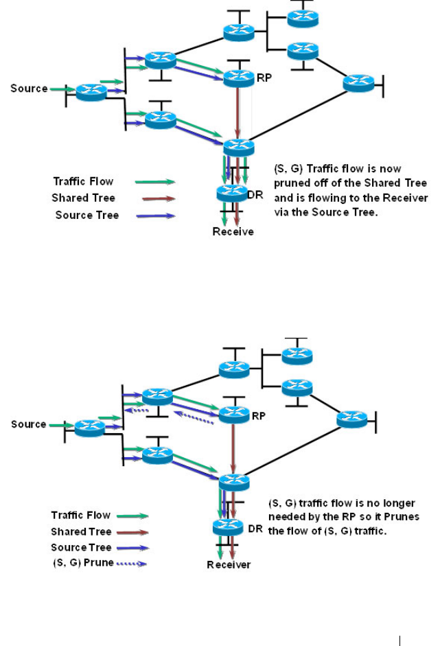
Managing IPv4 and IPv6 Multicast 1349
Figure 43-6. PIM-SM SPT—Part 3
• At this point, (S, G) traffic is now flowing directly from the first -hop
router to the last-hop router and from there to the receiver.
Figure 43-7. PIM-SM SPT—Part 4
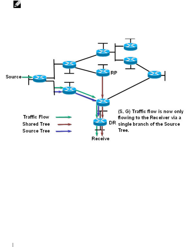
1350 Managing IPv4 and IPv6 Multicast
• At this point, the RP no longer needs the flow of (S, G) traffic since all
branches of the Shared Tree (in this case there is only one) have pruned off
the flow of (S, G) traffic.
• As a result, the RP will send (S, G) Prunes back toward the source to shut
off the flow of the now unnecessary (S, G) traffic to the RP.
Figure 43-8. PIM-SM SPT—Part 5
• As a result of the SPT-Switchover, (S, G) traffic is now flowing only from
the first-hop router to the last-hop router and from there to the receiver.
Notice that traffic is no longer flowing to the RP.
The PIM standard requires support for multi-hop RP in that a router running
PIM can act as an RP even if it is multiple router hops away from the
multicast source. This requires that the first-hop router perform
encapsulation of the multicast data and forward it as unicast toward the RP.
In practice, this encapsulation is almost always performed in software due to
the complexity of the operation. Likewise, the RP must perform de-
encapsulation and forwarding of the multicast packets in software. This
NOTE: This will occur if the RP has received an (S, G) RP-bit Prune on all
interfaces on the Shared Tree.

Managing IPv4 and IPv6 Multicast 1351
creates a performance problem in that it limits the number of packets that
can be processed and places a high load on the CPUs in the first hop and RP
routers, which can then adversely affect other router functions.
Dell Networking Optimizations to PIM-SM
Dell Networking switches perform the following optimizations to reduce the
impact of multicast encapsulation/de-encapsulation and provide a higher
level of multicast performance in the network.
• Limiting the number of packets sent to the RP by the first-hop router.
When a multicast data source (S) starts sending data destined for a
multicast group (G), the first-hop router receives these packets and traps
them to its local CPU. A Dell Networking first-hop router immediately
blocks further data packets in the stream and prevents them from reaching
the CPU. The first-hop router then unicast-encapsulates the first received
data packet in the form of a PIM Register message and software forwards it
to the RP.
When a Dell Networking first-hop router subsequently receives the PIM
Join from the RP, the block is replaced with a regular multicast forwarding
entry so that subsequent data packets are forwarded in the hardware.
If the initial Register message(s) does not reach the RP, or the PIM Join
sent in response does not reach the first-hop router, then the data stream
would never get forwarded. To solve this, the negative entry is timed out
and removed after 3 seconds so that the process can be repeated until it
succeeds.
• In Phase 3—Shortest Path Tree, the last-hop router initiates a switchover
to the SPT tree by sending a PIM (S,G) Join message towards the source as
soon as it receives the first data packet via the (*,G) shared tree. Per the
standard, this function is used to detect suboptimal routing of multicast
traffic. Dell Networking multicast eliminates the
SwitchToSptDesired(S,G) function and performs as if the
SwitchToSptDesired(S,G) function always returns “true” as soon as it
receives the first multicast packet instead of waiting for 30 seconds.
• Dell Networking RPs do not wait to receive the native multicast data but
immediately respond to the PIM (S,G) Join by sending a 'Register Stop'
message to the source's first-hop router to inform it that it can stop

1352 Managing IPv4 and IPv6 Multicast
sending the encapsulated Register messages. This removes the load from
the CPU of the first-hop router and the RP, as they no longer need to
encapsulate and de-encapsulate register messages with multicast data.
These optimizations significantly reduce the load on first-hop routers and
RPs to encapsulate/de-encapsulate PIM register messages and their associated
multicast data. In addition, the switchover to the SPT is initiated
immediately upon the first multicast packet reaching the last-hop router. This
leads to significantly faster response times for receiving the full multicast
stream directly from the first-hop router (as opposed to the typical
bandwidth-limited stream traversing the RP).
Using PIM-DM as the Multicast Routing Protocol
Unlike PIM-SM, PIM-DM creates source-based shortest-path distribution
trees that make use of reverse-path forwarding (RPF). PIM-DM assumes that
when a sender starts sending data, all downstream routers and hosts want to
receive a multicast datagram. PIM-DM initially floods multicast traffic
throughout the network. Routers that do not have any downstream neighbors
prune back the unwanted traffic. In addition to PRUNE messages, PIM-DM
makes use of graft and assert messages. Graft messages are used whenever a
new host wants to join the group. Assert messages are used to shutoff
duplicate flows on the same multi-access network.
There are two versions of PIM-DM. Version 2 does not use the IGMP
message; instead, it uses a message that is encapsulated in an IP package, with
protocol number 103. In Version 2, a Hello message is introduced in place of a
query message.
PIM-DM is appropriate for:
• Densely distributed receivers
• Few senders-to-many receivers (due to frequent flooding)
• High volume of multicast traffic
• Constant stream of traffic
To minimize the repeated flooding of datagrams and subsequent pruning
associated with a particular source-group (S,G) pair, PIM-DM uses a State
Refresh message. This message is sent by the router(s) directly connected to
the source and is propagated throughout the network. When received by a

Managing IPv4 and IPv6 Multicast 1353
router on its RPF interface, the State Refresh message causes an existing
prune state to be refreshed. State Refresh messages are generated periodically
by the router directly attached to the source.
What Is DVMRP?
DVMRP is an interior gateway protocol that is suitable for routing multicast
traffic within an autonomous system (AS). DVMRP should not be used
between different autonomous systems due to limitations with hop count and
scalability.
DVMRP exchanges probe packets with all its DVMRP-enabled routers, it
establishes two-way neighboring relationships, and it builds a neighbor table.
DVMRP exchanges report packets and creates a unicast topology table, with
which it builds the multicast routing table. This table is used to route the
multicast packets. Since every DVMRP router uses the same unicast routing
protocol, routing loops are avoided.
Understanding DVMRP Multicast Packet Routing
DVMRP is based on RIP; it forwards multicast datagrams to other routers in
the AS and constructs a forwarding table based on information it learns in
response. More specifically, it uses this sequence.
• A new multicast packet is forwarded to the entire multicast network, with
respect to the time-to-live (TTL) of the packet.
• The TTL restricts the area to be flooded by the message.
• All routers that do not have members on directly-attached subnetworks
send back
Prune messages
to the upstream router.
• The branches that transmit a prune message are deleted from the delivery
tree.
• The delivery tree which is spanning to all the members in the multicast
group, is constructed in the form of a DVMRP forwarding table.
NOTE: In addition to DVMRP, the switch supports the Protocol-Independent
Multicast (PIM) sparse-mode (PIM-SM) and dense-mode (PIM-SM) routing
protocol. Only one multicast routing protocol can be operational on the switch at
any time. If you enable DVMRP, PIM must be disabled. Similarly, if PIM is enabled,
DVMRP must be disabled.

1354 Managing IPv4 and IPv6 Multicast
Using DVMRP as the Multicast Routing Protocol
DVMRP is used to communicate multicast information between L3 switches
or routers. If a Dell Networking N2000, N3000, and N4000 series switches
handles inter-VLAN routing for IP traffic, including IP multicast traffic,
multicast routing might be required on the switch.
DVMRP is best suited for small networks where the majority of hosts request
a given multicast traffic stream. DVMRP is similar to PIM-DM in that it
floods multicast packets throughout the network and prunes branches where
the multicast traffic is not desired. DVMRP was developed before PIM-DM,
and it has several limitations that do not exist with PIM-DM.
You might use DVMRP as the multicast routing protocol if it has already been
widely deployed within the network.
Microsoft Network Load Balancing
Dell Networking switches support Microsoft Network Load Balancing (NLB)
in unicast mode only. When using Microsoft NLB, ensure that the Cluster
Operation Mode is configured to the default value of Unicast.

Managing IPv4 and IPv6 Multicast 1355
Default L3 Multicast Values
IP and IPv6 multicast is disabled by default. Table 43-2 shows the default
values for L3 multicast and the multicast protocols.
Table 43-2. L3 Multicast Defaults
Parameter Default Value
IPv4 Multicast Defaults
L3 Multicast Admin Mode Disabled
Maximum Multicast Routing Table
Entries
2048 (1536 IPv4/512 IPv6)
Switch sizes are as follows:
N2000/N3000—1536 IPv4 / 512 IPv6
N4000 —512 IPv4 / 256 IPv6
Static Multicast Routes None configured
Interface TTL Threshold 1
IGMP Defaults
IGMP Admin Mode Disabled globally and on all interfaces
IGMP Version v3
IGMP Robustness 2
IGMP Query Interval 125 seconds
IGMP Query Max Response Time 100 seconds
IGMP Startup Query Interval 31 seconds
IGMP Startup Query Count 2
IGMP Last Member Query Interval 1 second
IGMP Last Member Query Count 2
IGMP Proxy Interface Mode Disabled
IGMP Proxy Unsolicited Report Interval 1 second
MLD Defaults
MLD Admin Mode Disabled globally and on all interfaces
MLD Version v2

1356 Managing IPv4 and IPv6 Multicast
MLD Query Interval 125 seconds
MLD Query Max Response Time 10,000 milliseconds
MLD Last Member Query Interval 1000 milliseconds
MLD Last Member Query Count 2
MLD Proxy Interface Mode Disabled
MLD Proxy Unsolicited Report Interval 1 second
PIM Defaults
PIM Protocol Disabled globally and on all interfaces
PIM Hello Interval 30 seconds (when enabled on an interface)
PIM-SM Join/Prune Interval 60 seconds (when enabled on an interface)
PIM-SM BSR Border Disabled
PIM-SM DR Priority 1 (when enabled on an interface)
PIM Candidate Rendezvous Points (RPs) None configured
PIM Static RP None configured
PIM Source-Specific Multicast (SSM)
Range
None configured. Default SSM group
address is 232.0.0.0/8 for IPv4 multicast
and ff3x::/32 for IPv6 multicast.
PIM BSR Candidate Hash Mask Length 30 (IPv4)
126 (IPv6)
PIM BSR Candidate Priority 0
DVMRP Defaults
DVMRP Admin Mode Disabled globally and on all interfaces
DVMRP Version 3
DVMRP Interface Metric 1
Table 43-2. L3 Multicast Defaults (Continued)
Parameter Default Value
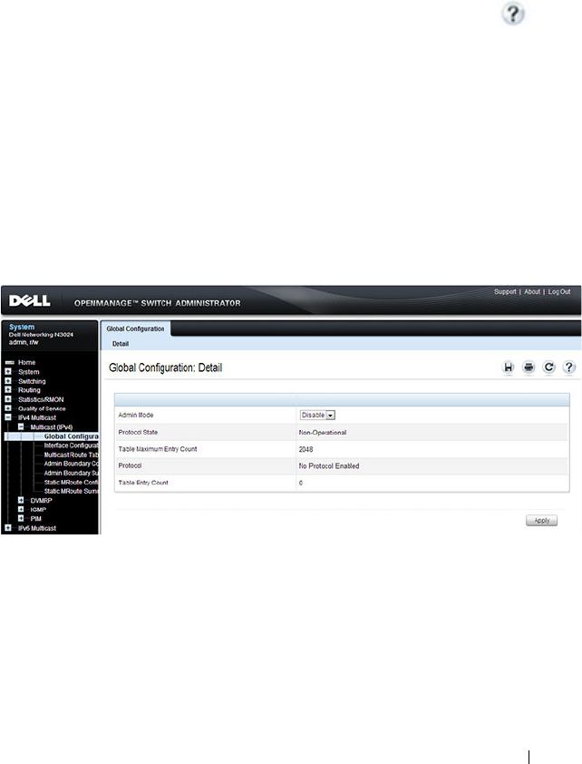
Managing IPv4 and IPv6 Multicast 1357
Configuring General IPv4 Multicast Features
(Web)
This section provides information about the OpenManage Switch
Administrator pages for configuring and monitoring the L3 multicast features
that are not protocol-specific on a Dell Networking N2000, N3000, and
N4000 series switches. For details about the fields on a page, click at the
top of the page.
Multicast Global Configuration
Use the Global Configuration
page to configure the administrative status of
Multicast Forwarding in the router, and to display global multicast
parameters.
To display the page, click IPv4 Multicast
→
Multicast
→
Global
Configuration in the navigation panel.
Figure 43-9. Multicast Global Configuration
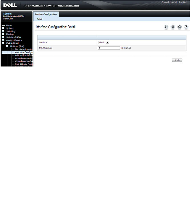
1358 Managing IPv4 and IPv6 Multicast
Multicast Interface Configuration
Use the Interface Configuration
page to configure the TTL threshold of a
multicast interface. At least one VLAN routing interface must be configured
on the switch before fields display on this page.
To display the page, click IPv4 Multicast
→
Multicast
→
Interface
Configuration in the navigation panel.
Figure 43-10. Multicast Interface Configuration
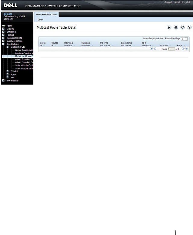
Managing IPv4 and IPv6 Multicast 1359
Multicast Route Table
Use the Route Table page to view information about the multicast routes in
the IPv4 multicast routing table.
To display the page, click IPv4 Multicast
→
Multicast
→
Multicast Route
Table Multicast Route Table
Figure 43-11. Multicast Route Table
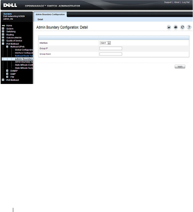
1360 Managing IPv4 and IPv6 Multicast
Multicast Admin Boundary Configuration
The definition of an administratively scoped boundary is a way to stop the
ingress and egress of multicast traffic for a given range of multicast addresses
on a given routing interface. Use the Admin Boundary Configuration
page to
configure a new or existing administratively scoped boundary. To see this
page, you must have configured a valid routing interface and multicast.
To display the page, click IPv4 Multicast
→
Multicast
→
Admin Boundary
Configuration in the navigation panel.
Figure 43-12. Multicast Admin Boundary Configuration
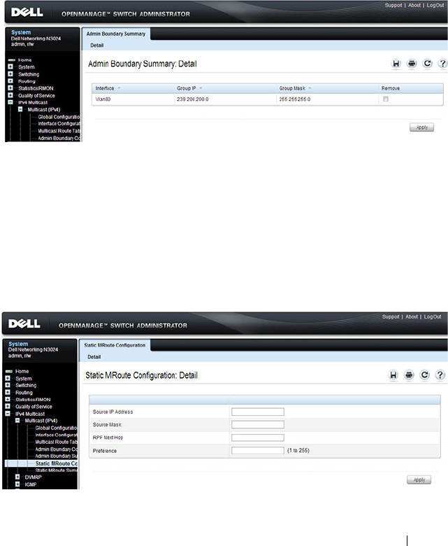
Managing IPv4 and IPv6 Multicast 1361
Multicast Admin Boundary Summary
Use the Admin Boundary Summary
page to display existing administratively
scoped boundaries.
To display the page, click IPv4 Multicast
→
Multicast
→
Admin Boundary
Summary in the navigation panel.
Figure 43-13. Multicast Admin Boundary Summary
Multicast Static MRoute Configuration
Use the Static MRoute Configuration
page to configure a new static entry in
the Mroute table or to modify an existing entry.
To display the page, click IPv4 Multicast
→
Multicast
→
Static MRoute
Configuration in the navigation panel.
Figure 43-14. Multicast Static MRoute Configuration
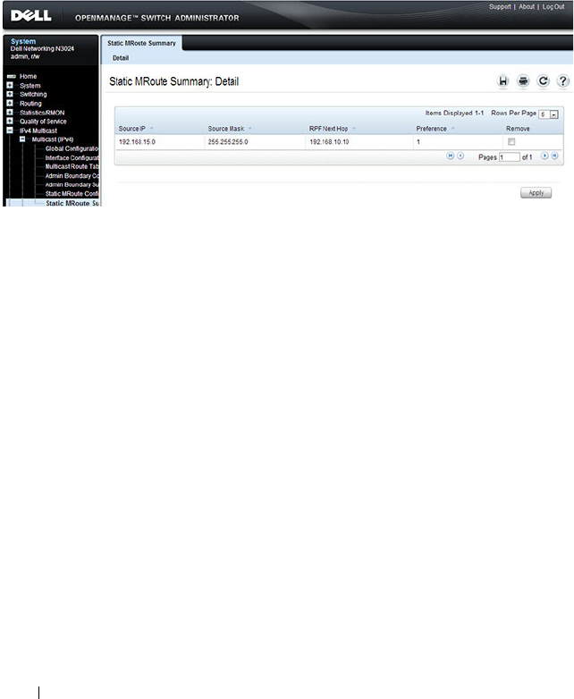
1362 Managing IPv4 and IPv6 Multicast
Multicast Static MRoute Summary
Use the Static MRoute Summary
page to display static routes and their
configurations.
To display the page, click IPv4 Multicast
→
Multicast
→
Static MRoute
Summary in the navigation panel.
Figure 43-15. Multicast Static MRoute Summary
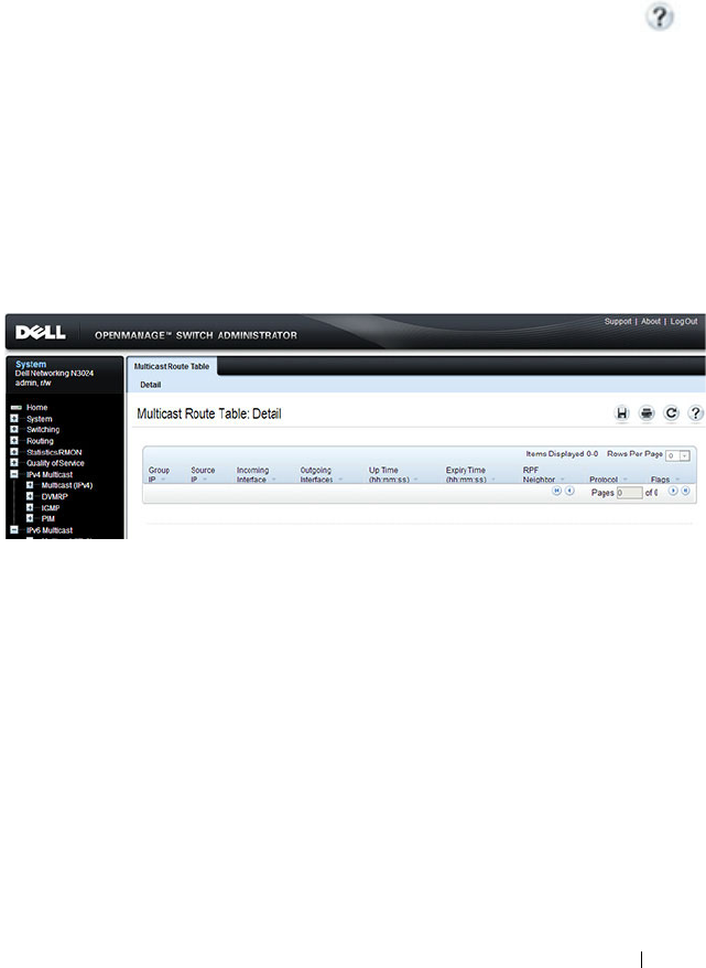
Managing IPv4 and IPv6 Multicast 1363
Configuring IPv6 Multicast Features (Web)
This section provides information about the OpenManage Switch
Administrator pages for configuring and monitoring the IPv6 multicast
features that are not protocol-specific on a Dell Networking N2000, N3000,
and N4000 series switches. For details about the fields on a page, click at
the top of the page.
IPv6 Multicast Route Table
Use the Multicast Route Table page to view information about the multicast
routes in the IPv6 multicast routing table.
To display the page, click IPv6 Multicast
→
Multicast
→
Multicast Route
Table.
Figure 43-16. IPv6 Multicast Route Table
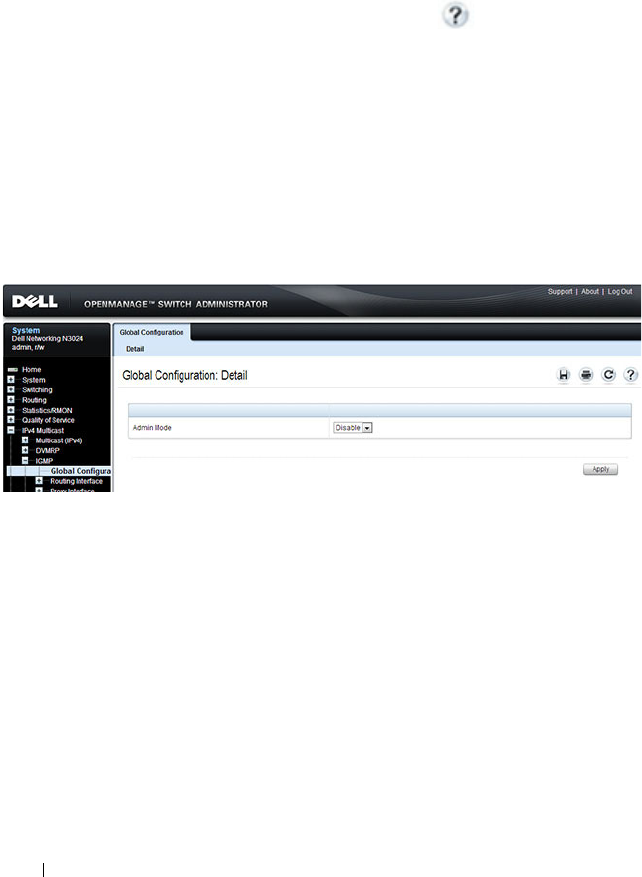
1364 Managing IPv4 and IPv6 Multicast
Configuring IGMP and IGMP Proxy (Web)
This section provides information about the OpenManage Switch
Administrator pages for configuring and monitoring the IGMP and IGMP
proxy features on a Dell Networking N2000, N3000, and N4000 series
switches. For details about the fields on a page, click at the top of the
page.
IGMP Global Configuration
Use the Global Configuration
page to set IGMP on the system to active or
inactive.
To display the page, click IPv4 Multicast
→
IGMP
→
Global Configuration
in the navigation panel.
Figure 43-17. IGMP Global Configuration
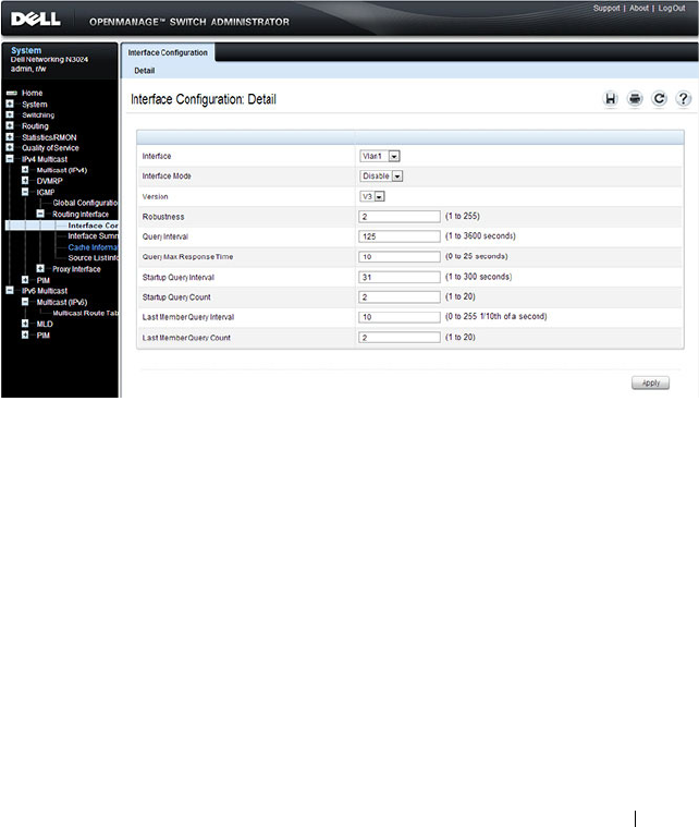
Managing IPv4 and IPv6 Multicast 1365
IGMP Interface Configuration
Use the Interface Configuration
page to configure and/or display router
interface parameters. You must configure at least one valid routing interface
before you can access this page and configure IP Multicast IGMP.
To display the page, click IPv4 Multicast
→
IGMP
→
Routing Interface
→
Interface Configuration in the navigation panel.
Figure 43-18. IGMP Interface Configuration
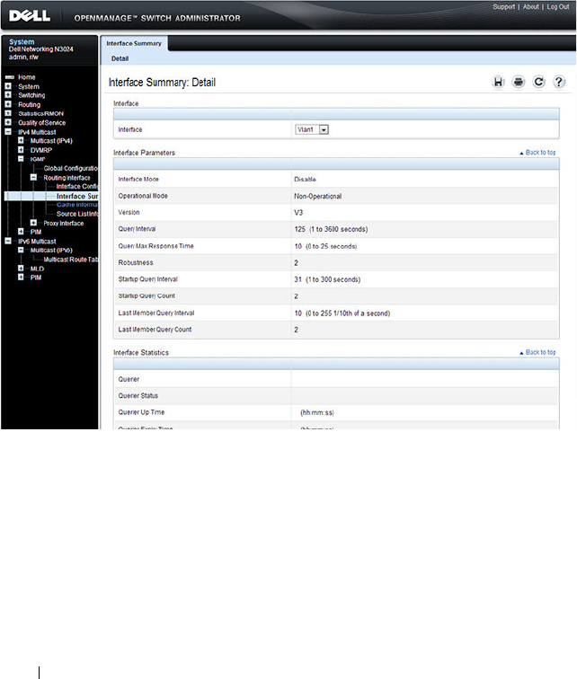
1366 Managing IPv4 and IPv6 Multicast
IGMP Interface Summary
Use the Interface Summary
page to display IGMP routing parameters and
data. You must configure at least one IGMP router interface to access this
page.
To display the page, click IPv4 Multicast
→
IGMP
→
Routing Interface
→
Interface Summary in the navigation panel.
Figure 43-19. IGMP Interface Summary
IGMP Cache Information
Use the Cache Information
page to display cache parameters and data for an
IP multicast group address. Group membership reports must have been
received on the selected interface for data to display on the page.
To display the page, click IPv4 Multicast
→
IGMP
→
Routing Interface
→
Cache Information in the navigation panel.
Managing IPv4 and IPv6 Multicast 1367
Figure 43-20. IGMP Cache Information
1368 Managing IPv4 and IPv6 Multicast
IGMP Interface Source List Information
Use the Source List Information
page to display detailed membership
information for an interface. Group membership reports must have been
received on the selected interface for data to display information.
To display the page, click IPv4 Multicast
→
IGMP
→
Routing Interface
→
Source List Information in the navigation panel.
Figure 43-21. IGMP Interface Source List Information
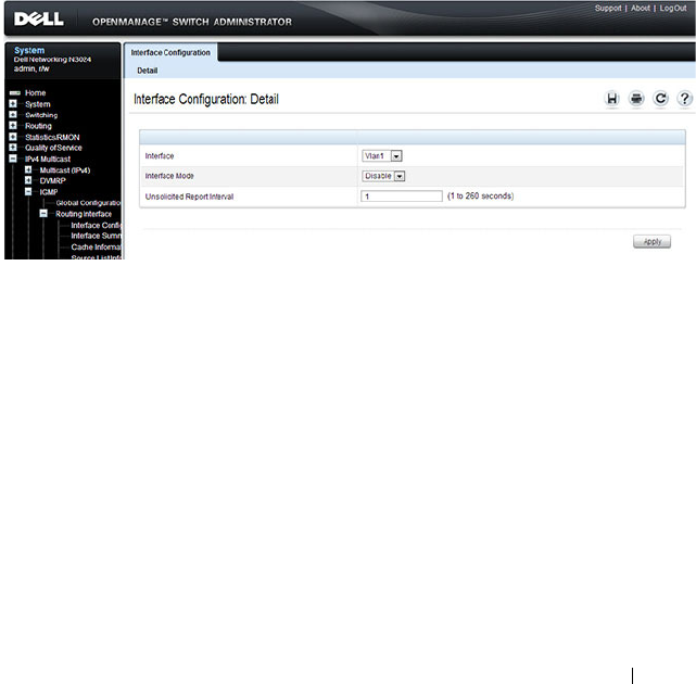
Managing IPv4 and IPv6 Multicast 1369
IGMP Proxy Interface Configuration
The IGMP Proxy is used by IGMP Router (IPv4 system) to enable the system
to issue IGMP host messages on behalf of hosts that the system discovered
through standard IGMP router interfaces. Thus, this feature acts as proxy to
all hosts residing on its router interfaces.
Use the Interface Configuration
page to configure IGMP proxy for a VLAN
interface. You must have configured at least one VLAN routing interface
before configuring or displaying data for an IGMP proxy interface, and it
should not be an IGMP routing interface.
To display the page, click IPv4 Multicast
→
IGMP
→
Proxy Interface
→
Interface Configuration in the navigation panel.
Figure 43-22. IGMP Proxy Interface Configuration
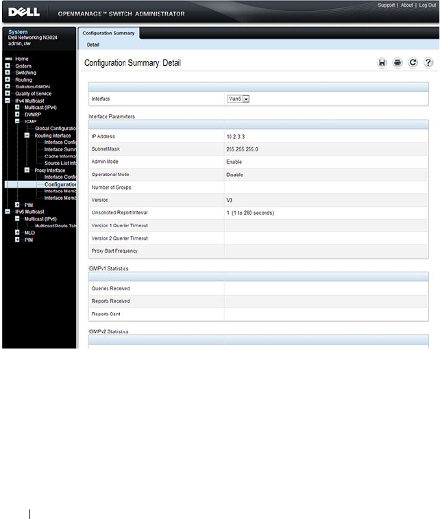
1370 Managing IPv4 and IPv6 Multicast
IGMP Proxy Configuration Summary
Use the Configuration Summary
page to display proxy interface
configurations by interface. You must have configured at least one VLAN
routing interface configured before data displays on this page.
To display the page, click IPv4 Multicast
→
IGMP
→
Proxy Interface
→
Configuration Summary in the navigation panel.
Figure 43-23. IGMP Proxy Configuration Summary
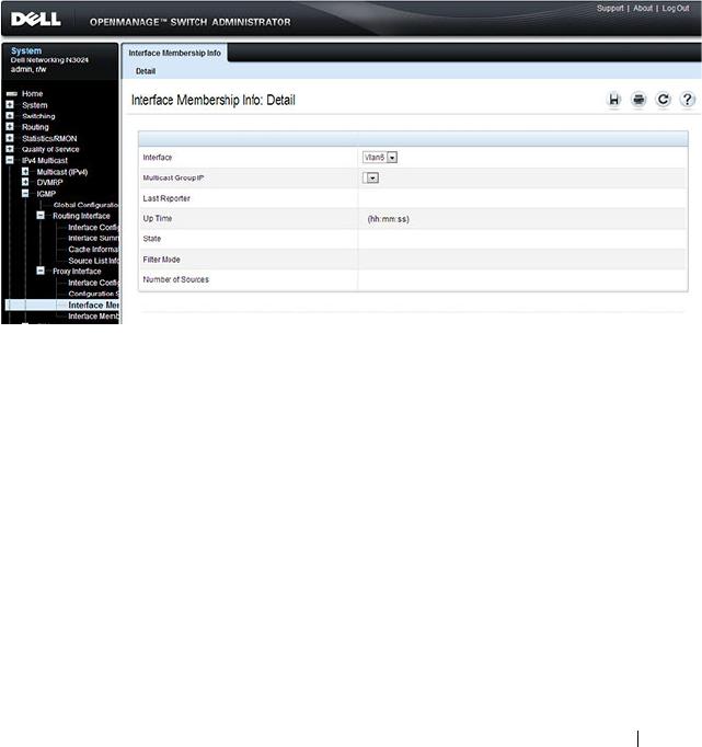
Managing IPv4 and IPv6 Multicast 1371
IGMP Proxy Interface Membership Info
Use the Interface Membership Info
page to display interface membership
data for a specific IP multicast group address. You must have configured at
least one VLAN routing interface before you can display interface
membership information, and it should not be an IGMP routing interface.
Also, if no group membership reports have been received on the selected
interface, no data displays on this page.
To display the page, click IPv4 Multicast
→
IGMP
→
Proxy Interface
→
Interface Membership Info in the navigation panel.
Figure 43-24. IGMP Proxy Interface Membership Info

1372 Managing IPv4 and IPv6 Multicast
Detailed IGMP Proxy Interface Membership Information
Use the Interface Membership Info Detailed
page to display detailed
interface membership data. You must have configured at least one VLAN
routing interface before you can display detailed interface membership
information, and it should not be an IGMP routing interface. Also, if no
group membership reports have been received on the selected interface you
cannot display data.
To display the page, click IPv4 Multicast
→
IGMP
→
Proxy Interface
→
Interface Membership Info Detailed in the navigation panel.
Figure 43-25. IGMP Proxy Interface Membership Info Detailed
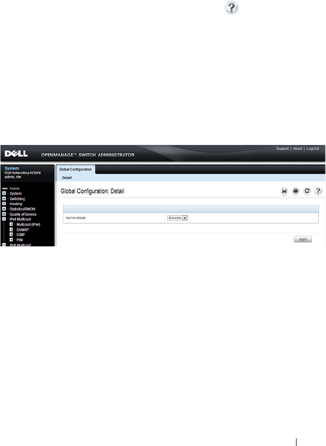
Managing IPv4 and IPv6 Multicast 1373
Configuring MLD and MLD Proxy (Web)
This section provides information about the OpenManage Switch
Administrator pages for configuring and monitoring the MLD and MLD
proxy features on a Dell Networking N2000, N3000, and N4000 series
switches. For details about the fields on a page, click at the top of the
page.
MLD Global Configuration
Use the Global Configuration page to administratively enable and disable
the MLD service.
To display the page, click IPv6 Multicast
→
MLD
→
Global Configuration
in the navigation panel.
Figure 43-26. MLD Global Configuration
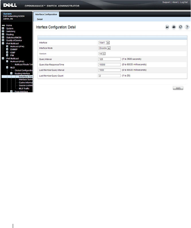
1374 Managing IPv4 and IPv6 Multicast
MLD Routing Interface Configuration
Use the Interface Configuration page to enable selected IPv6 router
interfaces to discover the presence of multicast listeners, the nodes who wish
to receive the multicast data packets, on its directly attached interfaces. To
access this page, click IPv6 Multicast
→
MLD
→
Routing Interface
→
Interface Configuration in the navigation panel.
Figure 43-27. MLD Routing Interface Configuration
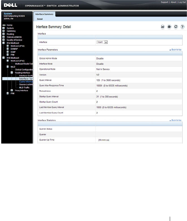
Managing IPv4 and IPv6 Multicast 1375
MLD Routing Interface Summary
Use the Interface Summary page to display information and statistics on a
selected MLD-enabled interface. You must configure at least one IGMP
VLAN routing interface to access this page.
To access this page, click IPv6 Multicast
→
MLD
→
Routing Interface
→
Interface Summary in the navigation panel.
Figure 43-28. MLD Routing Interface Summary
MLD Routing Interface Cache Information
The Interface Cache Information page displays cache parameters and data
for an IP multicast group address that has been reported to operational MLD
routing interfaces. You must configure at least one MLD VLAN routing
interface to access this page. Also, group membership reports must have been

1376 Managing IPv4 and IPv6 Multicast
received on the selected interface in order for data to be displayed here. To
access this page, click IPv6 Multicast
→
MLD
→
Routing Interface
→
Cache Information in the navigation panel.
Figure 43-29. MLD Routing Interface Cache Information
MLD Routing Interface Source List Information
The Interface Source List Information page displays detailed membership
information for an interface. You must configure at least one MLD VLAN
routing interface to access this page. Also, group membership reports must
have been received on the selected interface in order for data to be displayed
here. To access this page, click IPv6 Multicast
→
MLD
→
Routing Interface
→
Source List Information in the navigation panel.
Figure 43-30. MLD Routing Interface Source List Information
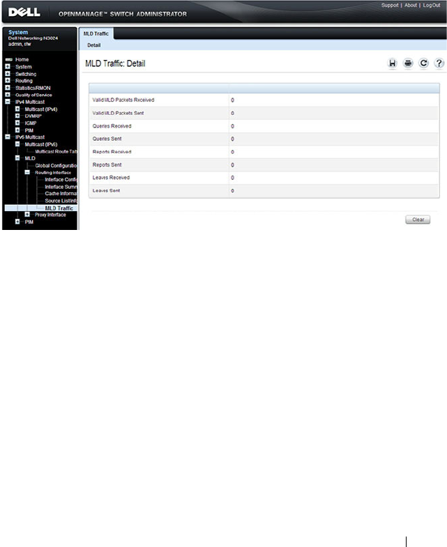
Managing IPv4 and IPv6 Multicast 1377
MLD Traffic
The MLD Traffic page displays summary statistics on the MLD messages
sent to and from the router.
To access this page, click IPv6 Multicast
→
MLD
→
Routing Interface
→
MLD Traffic in the navigation panel.
Figure 43-31. MLD Traffic
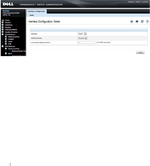
1378 Managing IPv4 and IPv6 Multicast
MLD Proxy Configuration
When you configure an interface in MLD proxy mode, it acts as a proxy
multicast host that sends MLD membership reports on one VLAN interface
for MLD Membership reports received on all other MLD-enabled VLAN
routing interfaces.
Use the Interface Configuration page to enable and disable ports as MLD
proxy interfaces. To display this page, click IPv6 Multicast
→
MLD
→
Proxy
Interface
→
Interface Configuration in the navigation panel.
Figure 43-32. MLD Proxy Interface Configuration
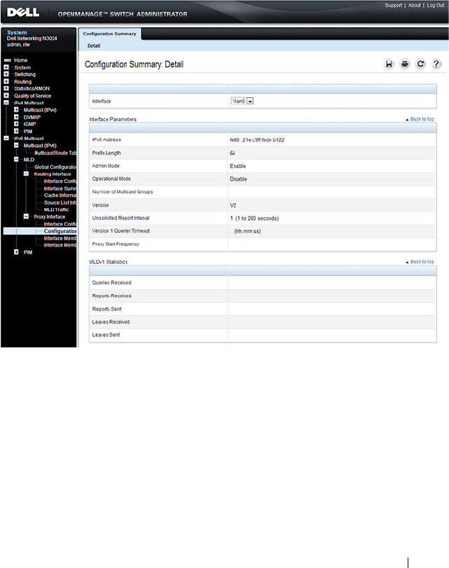
Managing IPv4 and IPv6 Multicast 1379
MLD Proxy Configuration Summary
Use the Configuration Summary page to view configuration and statistics on
MLD proxy-enabled interfaces. To display this page, click IPv6 Multicast
→
MLD
→
Proxy Interface
→
Configuration Summary in the navigation panel.
Figure 43-33. MLD Proxy Configuration Summary
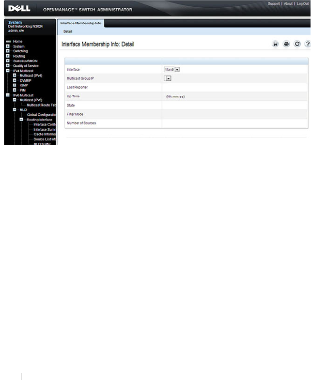
1380 Managing IPv4 and IPv6 Multicast
MLD Proxy Interface Membership Information
The Interface Membership Information page lists each IP multicast group
for which the MLD proxy interface has received membership reports. To
display this page, click IPv6 Multicast
→
MLD
→
Proxy interface
→
Interface Membership Info in the navigation panel.
Figure 43-34. Interface Membership Information

Managing IPv4 and IPv6 Multicast 1381
Detailed MLD Proxy Interface Membership Information
The Interface Membership Information Detailed page provides additional
information about the IP multicast groups for which the MLD proxy
interface has received membership reports. To display this page, click IPv6
Multicast
→
MLD
→
Proxy Interface
→
Interface Membership Info
Detailed in the navigation panel.
Figure 43-35. Interface Membership Information—Detailed

1382 Managing IPv4 and IPv6 Multicast
Configuring PIM for IPv4 and IPv6 (Web)
This section provides information about the OpenManage Switch
Administrator pages for configuring and monitoring PIM-SM and PIM-DM
for IPv4 and IPv6 multicast routing on a Dell Networking N2000, N3000, and
N4000 series switches. For details about the fields on a page, click at the
top of the page.
PIM Global Configuration
Use the Global Configuration
page to configure the administrative status of
PIM-DM or PIM-SM on the switch. It is strongly recommended that IGMP
be enabled on any switch on which IPv4 PIM is enabled and MLD be enabled
on any switch for which IPv6 PIM is enabled. This ensures that the multicast
router behaves as expected.
The CLI behavior is different than the web interface. Enabling PIM on an
IPv4 interface via the CLI automatically enables IGMP on the interface.
Likewise, enabling PIM on an IPv6 interface via the CLI automatically
enables MLD on the interface.
To display the page, click IPv4 Multicast
→
PIM
→
Global Configuration or
IPv6 Multicast
→
PIM
→
Global Configuration in the navigation panel.
Figure 43-36. PIM-DM Global Configuration
NOTE: The OpenManage Switch Administrator pages to configure IPv4 multicast
routing and IPv6 multicast routing is very similar. The figures in this section show
the IPv4 multicast configuration pages. To configure IPv6 multicast with PIM, use
the pages available from the IPv6 Multicast → PIM menu.
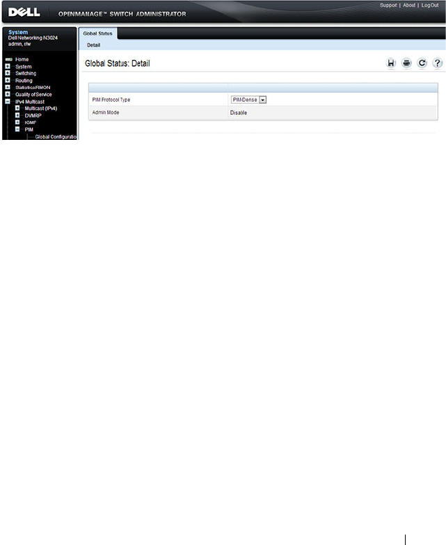
Managing IPv4 and IPv6 Multicast 1383
PIM Global Status
Use the Global Status
page to view the administrative status of PIM-DM or
PIM-SM on the switch.
To display the page, click IPv4 Multicast
→
PIM
→
Global Status or IPv6
Multicast
→
PIM
→
Global Status in the navigation panel.
Figure 43-37. PIM Global Status

1384 Managing IPv4 and IPv6 Multicast
PIM Interface Configuration
Use the Interface Configuration
page to configure specific VLAN routing
interfaces with PIM.
To display the page, click IPv4 Multicast
→
PIM
→
Interface Configuration
or IPv6 Multicast
→
PIM
→
Interface Configuration in the navigation
panel.
Figure 43-38. PIM Interface Configuration
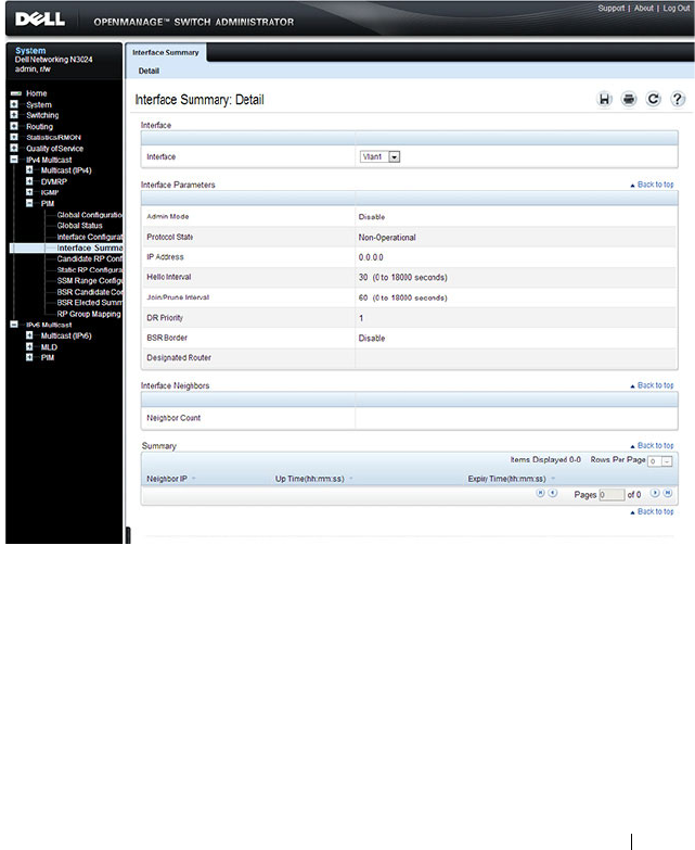
Managing IPv4 and IPv6 Multicast 1385
PIM Interface Summary
Use the Interface Summary
page to display a PIM-enabled VLAN routing
interface interface and its settings.
To display the page, click IPv4 Multicast
→
PIM
→
Interface Summary or
IPv6 Multicast
→
PIM
→
Interface Summary in the navigation panel.
Figure 43-39. PIM Interface Summary
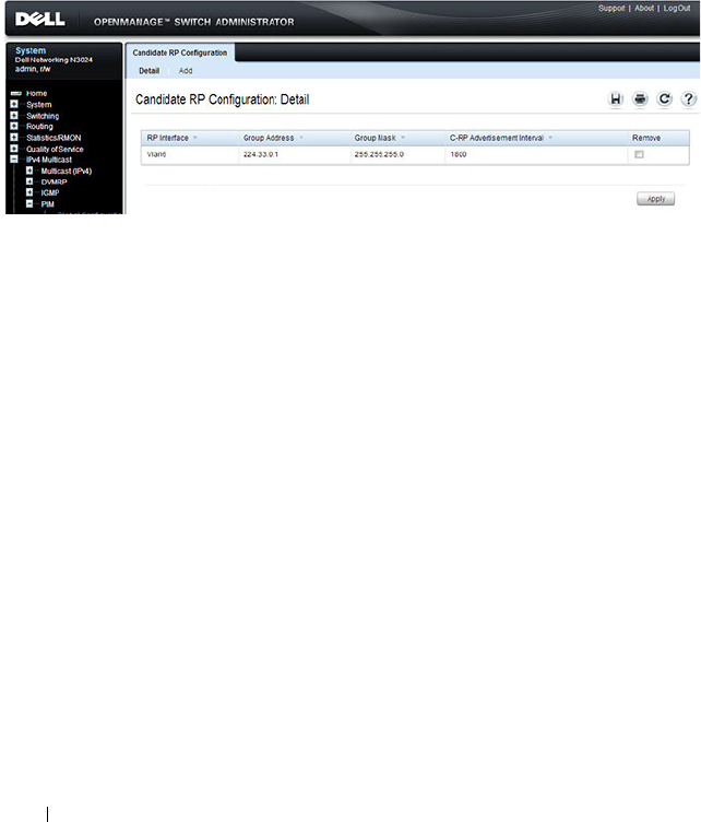
1386 Managing IPv4 and IPv6 Multicast
Candidate RP Configuration
The Candidate RP is configured on the Add Candidate RP page. Use the
Candidate RP Configuration page to display and delete the configured
rendezvous points (RPs) for each port using PIM.
To access the page, click IPv4 Multicast
→
PIM
→
Candidate RP
Configuration or IPv6 Multicast
→
PIM
→
Candidate RP Configuration.
Figure 43-40. Candidate RP Configuration
Adding a Candidate RP
To add PIM Candidate rendezvous points (RPs) for each IP multicast group:
1
Open the
Candidate RP Configuration
page.
2
Click
Add
.
The
Add Candidate RP
page displays.

Managing IPv4 and IPv6 Multicast 1387
Figure 43-41. Add Candidate RP
3
Select the VLAN interface for which the Candidate RP is to be configured.
4
Enter the group address transmitted in Candidate-RP-Advertisements.
5
Enter the prefix length transmitted in Candidate-RP-Advertisements to
fully identify the scope of the group which the router supports if elected as
a Rendezvous Point.
6
Click
Apply Changes
.
The new Candidate RP is added, and the device is updated.
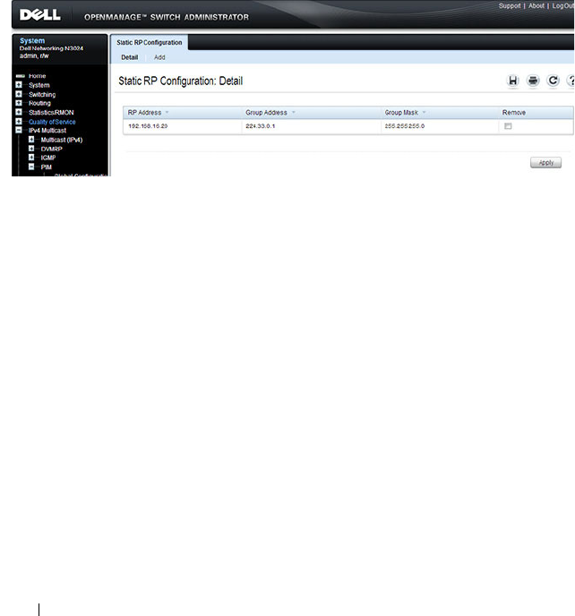
1388 Managing IPv4 and IPv6 Multicast
Static RP Configuration
Use the Static RP Configuration
page to display or remove the configured
RP. The page also allows adding new static RPs by clicking the Add button.
Only one RP address can be used at a time within a PIM domain. If the PIM
domain uses the BSR to dynamically learn the RP, configuring a static RP is
not required. However, you can configure the static RP to override any
dynamically learned RP from the BSR.
To access the page, click IPv4 Multicast
→
PIM
→
Static RP Configuration
or IPv6 Multicast
→
PIM
→
Static RP Configuration.
Figure 43-42. Static RP Configuration
Adding a Static RP
To add a static RP for the PIM router.
1
Open the
Static RP Configuration
page.
2
Click
Add
.
The
Add Static RP
page displays.
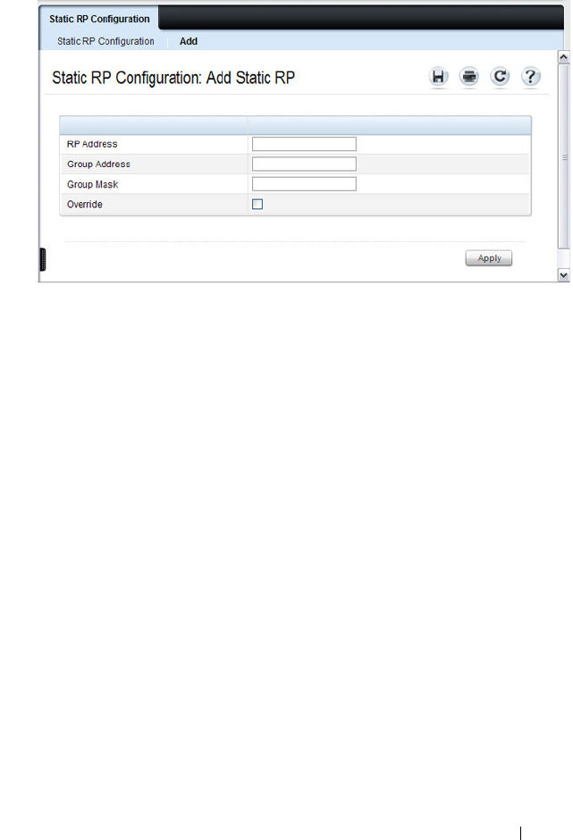
Managing IPv4 and IPv6 Multicast 1389
Figure 43-43. Add Static RP
3
Enter the IP address of the RP for the group range.
4
Enter the group address of the RP.
5
Enter the group mask of the RP.
6
Check the
Override
option to configure the static RP to override the
dynamic (candidate) RPs learned for same group ranges.
7
Click
Apply
.
The new Static RP is added, and the device is updated.
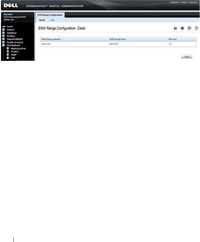
1390 Managing IPv4 and IPv6 Multicast
SSM Range Configuration
Use this page to display or remove the Source Specific Multicast (SSM) group
IP address and group mask for the PIM router.
To display the page, click IPv4 Multicast
→
PIM
→
SSM Range
Configuration or IPv6 Multicast
→
PIM
→
SSM Range Configuration.
Figure 43-44. SSM Range Configuration
Adding an SSM Range
To add the Source-Specific Multicast (SSM) Group IP Address and Group
Mask (IPv4) or Prefix Length (IPv6) for the PIM router:
1
Open the
SSM Range Configuration
page.
2
Click
Add
.
The
Add SSM Range
page displays.

Managing IPv4 and IPv6 Multicast 1391
Figure 43-45. Add SSM Range
3
Click the Add Default SSM Range check box to add the default SSM
Range. The default SSM Range is 232.0.0.0/8 for IPv4 multicast and
ff3x::/32 for IPv6 multicast.
4
Enter the
SSM Group IP Address.
5
Enter the SSM Group Mask (IPv4) or SSM Prefix Length (IPv6).
6
Click
Apply
.
The new SSM Range is added, and the device is updated.
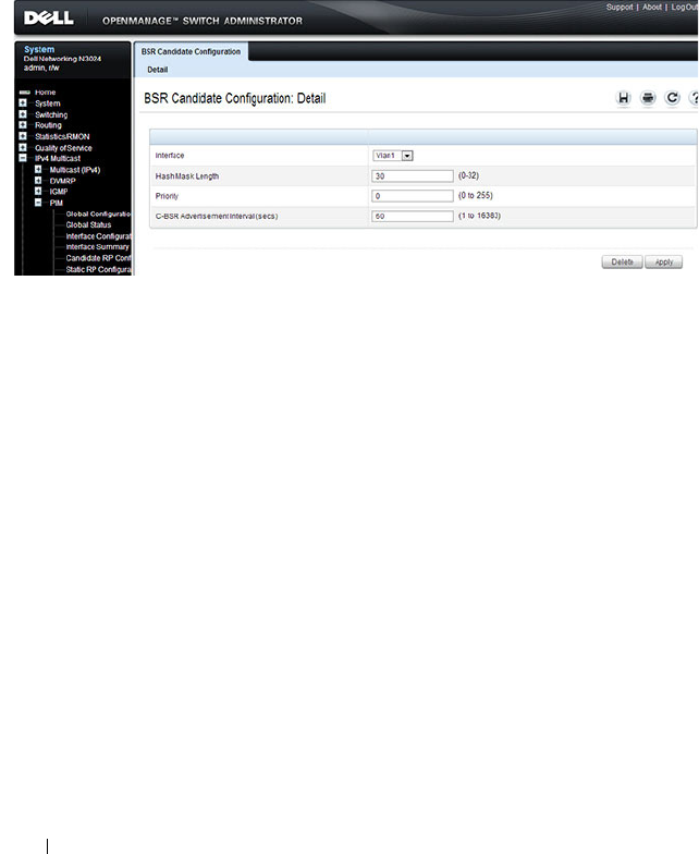
1392 Managing IPv4 and IPv6 Multicast
BSR Candidate Configuration
Use this page to configure information to be used if the interface is selected
as a bootstrap router.
To display the page, click IPv4 Multicast
→
PIM
→
BSR Candidate
Configuration or IPv6 Multicast
→
PIM
→
BSR Candidate Configuration.
Figure 43-46. BSR Candidate Configuration

Managing IPv4 and IPv6 Multicast 1393
BSR Candidate Summary
Use this page to display information about the configured BSR candidates. To
display this page, click IPv4 Multicast
→
PIM
→
BSR Candidate Summary
or IPv6 Multicast
→
PIM
→
BSR Elected Summary.
Figure 43-47. BSR Elected Summary
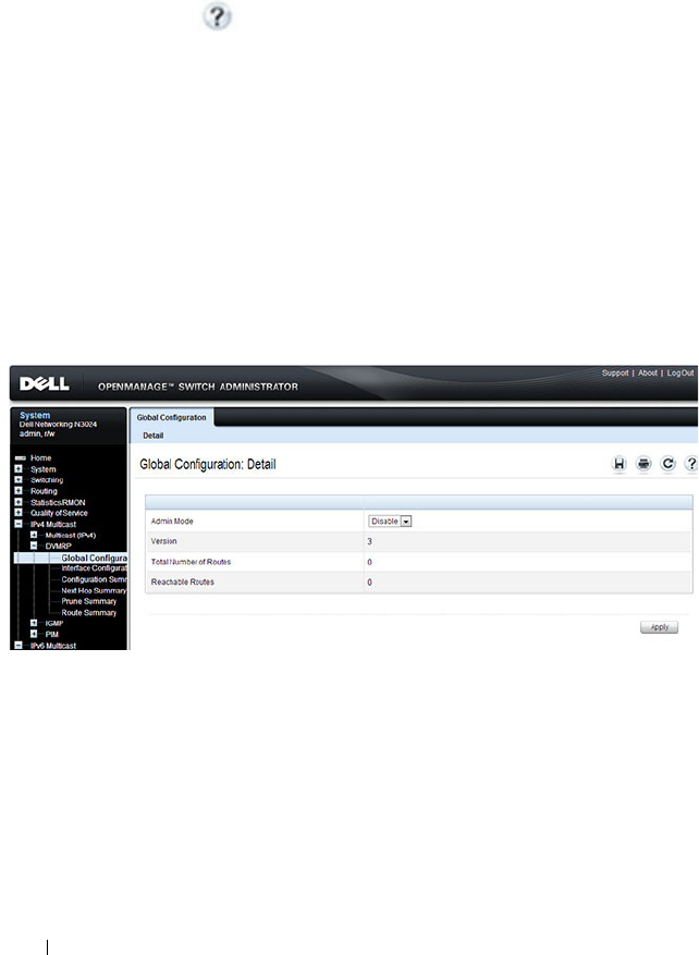
1394 Managing IPv4 and IPv6 Multicast
Configuring DVMRP (Web)
This section provides information about the OpenManage Switch
Administrator pages for configuring and monitoring DVMRP on a Dell
Networking N2000, N3000, and N4000 series switches. For details about the
fields on a page, click at the top of the page.
DVMRP Global Configuration
Use the Global Configuration
page to configure global DVMRP settings. It is
strongly recommended that IGMP be enabled on any switch on which
DVMRP is enabled. The use cases for enabling DVMRP without IGMP are
few, and enabling IGMP ensures that the multicast router behaves as
expected.
To display the page, click IPv4 Multicast
→
DVMRP
→
Global
Configuration in the navigation panel.
Figure 43-48. DVMRP Global Configuration
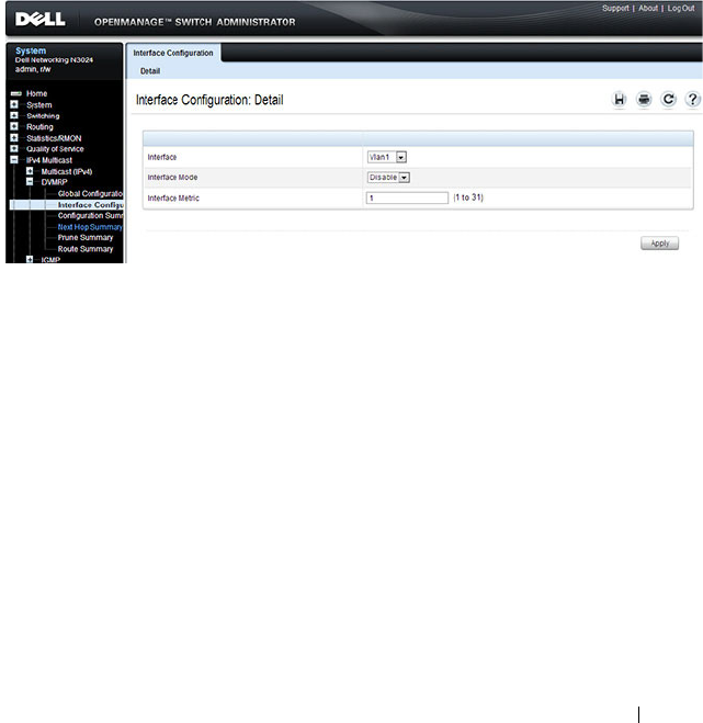
Managing IPv4 and IPv6 Multicast 1395
DVMRP Interface Configuration
Use the Interface Configuration
page to configure a DVMRP VLAN routing
interface. You must configure at least one router interface before you
configure a DVMRP interface. Otherwise you see a message telling you that
no router interfaces are available, and the configuration screen is not
displayed. It is strongly recommended that IGMP be enabled on any interface
on which DVMRP is enabled. This ensures that the multicast router behaves
as expected.
To display the page, click IPv4 Multicast
→
DVMRP
→
Interface
Configuration in the navigation panel.
Figure 43-49. DVMRP Interface Configuration
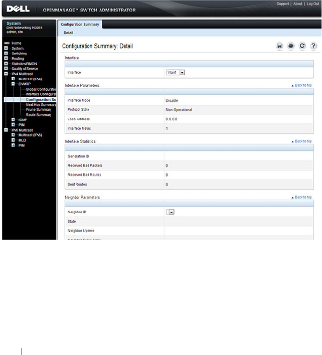
1396 Managing IPv4 and IPv6 Multicast
DVMRP Configuration Summary
Use the Configuration Summary
page to display the DVMRP configuration
and data for a selected interface. You must configure at least one VLAN
routing interface before you can display data for a DVMRP interface.
Otherwise you see a message telling you that no VLAN router interfaces are
available, and the configuration summary screen is not displayed.
To display the page, click IPv4 Multicast
→
DVMRP
→
Configuration
Summary in the navigation panel.
Figure 43-50. DVMRP Configuration Summary
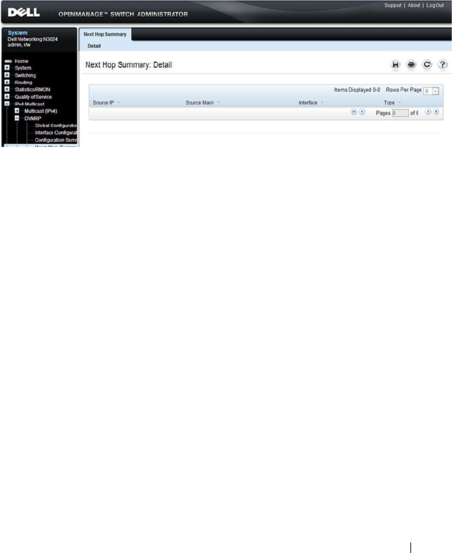
Managing IPv4 and IPv6 Multicast 1397
DVMRP Next Hop Summary
Use the Next Hop Summary
page to display the next hop summary by Source
IP.
To display the page, click IPv4 Multicast
→
DVMRP
→
Next Hop Summary
in the navigation panel.
Figure 43-51. DVMRP Next Hop Summary
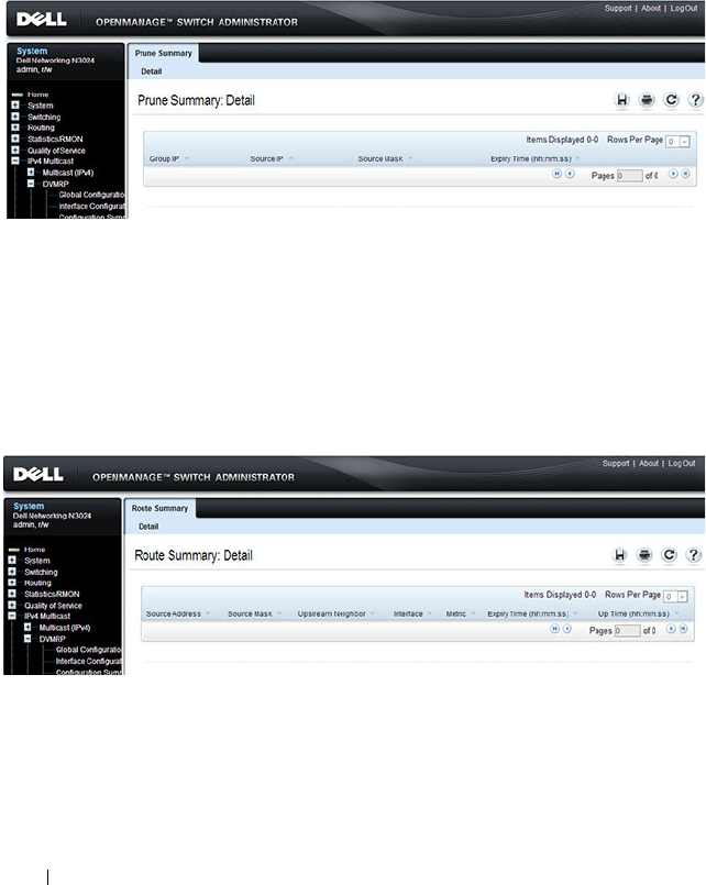
1398 Managing IPv4 and IPv6 Multicast
DVMRP Prune Summary
Use the Prune Summary
page to display the prune summary by Group IP.
To display the page, click IPv4 Multicast
→
DVMRP
→
Prune Summary in
the navigation panel.
Figure 43-52. DVMRP Prune Summary
DVMRP Route Summary
Use the Route Summary
page to display the DVMRP route summary.
To display the page, click IPv4 Multicast
→
DVMRP
→
Route Summary in
the navigation panel.
Figure 43-53. DVMRP Route Summary

Managing IPv4 and IPv6 Multicast 1399
Configuring L3 Multicast Features (CLI)
This section provides information about the commands you use to configure
general IPv4 multicast settings on the switch. For more information about the
commands, see the
Dell Networking N2000, N3000, and N4000 Series
Switches CLI Reference Guide
at support.dell.com/manuals.
Configuring and Viewing IPv4 Multicast Information
Beginning in Privileged EXEC mode, use the following commands to enable
IPv4 multicast on the switch and to view and configure other general
multicast settings.
Command Purpose
configure Enter global configuration mode.
ip multicast Enable IPv4/IPv6 multicast on the switch.
ip mroute
source-address
mask rpf-address preference
Create a static multicast route for a source range.
•
source-address
— The IP address of the multicast data
source.
•
mask
— The IP subnet mask of the multicast data
source.
•
rpf-address
— The IP address of the next hop towards
the source.
•
preference
— The cost of the route (Range: 1–255).
interface vlan
vlan-id
Enter Interface Configuration mode for the specified
VLAN.
ip mcast boundary
groupipaddr mask
Add an administrative scope multicast boundary
specified by the multicast group IP address
(
groupipaddr
) and group IP subnet mask (
mask
) for
which this multicast administrative boundary is
applicable.
The group IP address valid range is 239.0.0.0 to
239.255.255.255.
ip multicast ttl-threshold
ttlvalue
Apply a Time to Live (TTL) value to the interface. The
ttlvalue
is the TTL threshold which is applied to the
multicast data packets forwarded through the interface.

1400 Managing IPv4 and IPv6 Multicast
exit Exit to Global Config mode.
exit Exit to Privileged EXEC mode.
show ip multicast View system-wide multicast information.
show ip mcast boundary
{vlan
vlan-id
| all}
View all the configured administrative scoped multicast
boundaries.
show ip mcast mroute
{detail | summary}
View a summary or all the details of the multicast table.
show mac address-table
multicast [count]
View information about the entries in the multicast
address table.
show ip mcast mroute
group
groupipaddr
{detail |
summary}
View the multicast configuration settings such as flags,
timer settings, incoming and outgoing interfaces, RPF
neighboring routers, and expiration times of all the
entries in the multicast mroute table containing the
groupipaddr
value.
show ip mcast mroute
source
sourceipaddr
{summary |
groupipaddr
}
View the multicast configuration settings such as flags,
timer settings, incoming and outgoing interfaces, RPF
neighboring routers, and expiration times of all the
entries in the multicast mroute table containing the
sourceipaddr
or
sourceipaddr
|
groupipaddr
pair
value(s).
show ip mcast mroute static
[
sourceipaddr
]
View all the static routes configured in the static mcast
table if it is specified or display the static route
associated with the particular
sourceipaddr
.
Command Purpose

Managing IPv4 and IPv6 Multicast 1401
Configuring and Viewing IPv6 Multicast Route Information
Beginning in Privileged EXEC mode, use the following commands to
configure static IPv6 multicast routes on the switch and to view IPv6
multicast table information.
Command Purpose
configure Enter global configuration mode.
ip multicast Enable IPv4/IPv6 multicast routing.
ipv6 mroute
source-
address/prefix-length rpf-
address
[interface vlan
vlan-id
]
preference
Create a static multicast route for a source range.
•
source-address/prefix-length
— The IPv6 address of the
multicast data source.
•
rpf-address
— The IPv6 address of the next hop towards
the source.
•
vlan-id
—If the
rpf-address
is a link-local address then
the VLAN interface must also be specified. If the
rpf-
address
is a global address, then specifying the VLAN
interface is not required.
•
preference
— The cost of the route (Range: 1–255).
exit Exit to Privileged EXEC mode.
show ipv6 mroute
{detail | summary}
View a summary or all the details of the multicast table.
show ipv6 mroute group
groupipaddr
{detail |
summary}
View the multicast configuration settings such as flags,
timer settings, incoming and outgoing interfaces, RPF
neighboring routers, and expiration times of all the entries
in the multicast mroute table containing the
groupipaddr
value.
show ipv6 mroute source
sourceipaddr
{summary
|
groupipaddr
}
View the multicast configuration settings such as flags,
timer settings, incoming and outgoing interfaces, RPF
neighboring routers, and expiration times of all the entries
in the multicast mroute table containing the
sourceipaddr
or
sourceipaddr
|
groupipaddr
pair value(s).
show ipv6 mroute static
[
sourceipaddr
]
View all the static routes configured in the static mcast
table if it is specified or display the static route associated
with the particular
sourceipaddr
.

1402 Managing IPv4 and IPv6 Multicast
Configuring and Viewing IGMP
Beginning in Privileged EXEC mode, use the following commands to
configure IGMP on the switch and on VLAN routing interfaces and to view
IGMP information.
Command Purpose
configure Enter global configuration mode.
ip multicast Enable IPv4/IPv6 multicast routing.
ip igmp Enable IGMP on the switch.
interface vlan
vlan-id
Enter Interface Configuration mode for the specified
VLAN.
ip igmp Enable IGMP on the interface.
ip igmp version
version
Set the version of IGMP for an interface.
The
version
variable can be 1, 2, or 3.
ip igmp robustness
robustness
Configure the robustness that allows tuning of the
interface, that is, tuning for the expected packet loss on a
subnet. If a subnet is expected to have significant loss, the
robustness variable may be increased for the interface.
The range for
robustness
is 1–255.
ip igmp query-interval
seconds
Configure the query interval for the specified interface.
The query interval determines how fast IGMP Host-
Query packets are transmitted on this interface.
The range for
seconds
is 0–3600 seconds.
ip igmp query-max-
response-time
seconds
Configure the maximum response time interval for the
specified interface. It is the maximum query response
time advertised in IGMPv2 queries on this interface.
The range for
seconds
is 0–25 seconds.
ip igmp startup-query-
interval
seconds
Set the interval between general queries sent at startup on
the interface.
The range for
seconds
is 0–300 seconds.

Managing IPv4 and IPv6 Multicast 1403
ip igmp startup-query-
count
count
Set the number of queries sent out on startup —at
intervals equal to the startup query interval for the
interface.
The range for
count
is 1–20.
ip igmp last-member-
query-interval
tenthsofseconds
Configure the Maximum Response Time inserted in
Group-Specific Queries which are sent in response to
Leave Group messages.
The range is 0–255 tenths of a second.
ip igmp last-member-
query-count
count
Set the number of Group-Specific Queries sent before the
router assumes that there are no local members on the
interface.
The range for
count
is 1–20.
CTRL + Z Exit to Privileged EXEC mode.
show ip igmp View system-wide IGMP information.
show ip igmp interface
[vlan
vlan-id
]
View IGMP information for all interfaces or for the
specified interface.
show ip igmp interface
stats [vlan
vlan-id
]
View IGMP statistics for all interfaces or for the specified
interface.
show ip igmp groups
[interface vlan
vlan-id
]
View the registered multicast groups on the interface.
show ip igmp
membership
View the list of interfaces that have registered in any
multicast group.
Command Purpose

1404 Managing IPv4 and IPv6 Multicast
Configuring and Viewing IGMP Proxy
Beginning in Privileged EXEC mode, use the following commands to
configure the upstream VLAN routing interface as an IGMP proxy. The
IGMP proxy issues host messages on behalf of the hosts that have been
discovered on IGMP-enabled interfaces. The upstream interface is the
interface closest to the root multicast router, which should be running IGMP.
NOTE: Configure only the upstream interface as the IGMP proxy. IGMP should
be enabled on all downstream interfaces. IP routing and IP multicast must be
enabled on the switch for the IGMP proxy feature to operate.
Command Purpose
configure Enter global configuration mode.
interface vlan
vlan-id
Enter Interface Configuration mode for the
specified VLAN.
ip igmp-proxy Configure the interface as an IGMP proxy
interface.
ip igmp-proxy reset-status (Optional) Reset the host interface status
parameters of the IGMP Proxy.
ip igmp-proxy unsolicit-rprt-
interval
seconds
Configure the unsolicited report interval for the
IGMP proxy interface.
The range for
seconds
is 0–260 seconds.
CTRL + Z Exit to Privileged EXEC mode.
show ip igmp-proxy View a summary of the host interface status
parameters.
show ip igmp-proxy interface View a detailed list of the host interface status
parameters. This command displays information
only when IGMP Proxy is operational.
show ip igmp-proxy groups View a table of information about multicast
groups that IGMP Proxy reported. This
command displays information only when IGMP
Proxy is operational.

Managing IPv4 and IPv6 Multicast 1405
Configuring and Viewing MLD
Beginning in Privileged EXEC mode, use the following commands to
configure MLD on the switch and on VLAN routing interfaces and to view
IGMP information.
Command Purpose
configure Enter global configuration mode.
ip multicast Enable IPv4/IPv6 multicast routing.
ipv6 mld router Enable MLD on the switch.
interface vlan
vlan-id
Enter Interface Configuration mode for the
specified VLAN.
ipv6 mld router Enable MLD on the interface.
ipv6 mld version
version
Set the version of MLD for an interface.
The
version
variable can be 1 or 2.
ipv6 mld query-interval
seconds
Configure the query interval for the specified
interface. The query interval determines how fast
MLD Host-Query packets are transmitted on this
interface.
The range for
seconds
is 0–3600 seconds.
ipv6 mld query-max-response-
time
seconds
Configure the maximum response time interval
for the specified interface. It is the maximum
query response time advertised in MLD queries
on this interface.
The range for
seconds
is 0–25 seconds.
ipv6 mld last-member-query-
interval
tenthsofseconds
Set the last member query interval for the MLD
interface, which is the value of the maximum
response time parameter in the group-specific
queries sent out of this interface.
The range is 0–65535 milliseconds.
ipv6 mld last-member-query-
count
count
Set the number of listener-specific queries sent
before the router assumes that there are no local
members on the interface.
The range for
count
is 1–20.
CTRL + Z Exit to Privileged EXEC mode.

1406 Managing IPv4 and IPv6 Multicast
Configuring and Viewing MLD Proxy
Beginning in Privileged EXEC mode, use the following commands to
configure the upstream VLAN routing interface as an MLD proxy. The MLD
proxy issues host messages on behalf of the hosts that have been discovered
on the downstream MLD-enabled interfaces. The upstream interface is the
interface closest to the root multicast router, which should be running IGMP.
show ipv6 mld interface [vlan
vlan-id
]
View MLD information for all interfaces or for
the specified interface.
show ipv6 mld interface stats
[vlan
vlan-id
]
View MLD statistics for all interfaces or for the
specified interface.
show ipv6 mld groups [interface
vlan
vlan-id
]
View the registered multicast groups on the
interface.
show ipv6 mld membership View the list of interfaces that have registered in
any multicast group.
NOTE: Configure only the upstream interface as the MLD proxy. MLD should be
enabled on all downstream interfaces. IPv6 routing must be enabled on the
switch for the MLD proxy feature to operate.
Command Purpose
configure Enter global configuration mode.
interface vlan
vlan-id
Enter Interface Configuration mode for the
specified VLAN.
ipv6 mld-proxy Configure the interface as an MLD proxy
interface.
ipv6 mld-proxy reset-status (Optional) Reset the host interface status
parameters of the MLD Proxy.
ipv6 igmp-proxy unsolicit-rprt-
interval
seconds
Configure the unsolicited report interval for the
MLD proxy interface.
The range for
seconds
is 0–260 seconds.
CTRL + Z Exit to Privileged EXEC mode.
Command Purpose

Managing IPv4 and IPv6 Multicast 1407
Configuring and Viewing PIM-DM for IPv4 Multicast Routing
Beginning in Privileged EXEC mode, use the following commands to
configure PIM-DM for IPv4 multicast routing on the switch and on VLAN
routing interfaces and to view PIM-DM information.
show ipv6 mld-proxy View a summary of the host interface status
parameters.
show ipv6 mld-proxy interface View a detailed list of the host interface status
parameters. This command displays information
only when MLD Proxy is operational.
show ipv6 mld-proxy groups View a table of information about multicast
groups that MLD Proxy reported. This command
displays information only when MLD Proxy is
operational.
Command Purpose
configure Enter global configuration mode.
ip routing Enable ip routing. Routing is required for PIM to
calculate where to prune the multicast trees.
ip pim dense Enable PIM-DM on the switch.
ip igmp Enable IGMP. IGMP is required for PIM to operate
properly.
ip multicast Enable IPv4/IPv6 multicast routing.
interface vlan
vlan-id
Enter Interface Configuration mode for the specified
VLAN.
ip pim Enable PIM-DM on the interface.
ip igmp Enable IGMP on the interface. IGMP is required for
proper operation of PIMDM
ip pim hello-interval
seconds
Specify the number of seconds (range: 0–65535) to
wait between sending PIM hello messages on the
interface.
exit Exit to Privileged EXEC mode.
show ip pim View system-wide PIM information.
Command Purpose

1408 Managing IPv4 and IPv6 Multicast
Configuring and Viewing PIM-DM for IPv6 Multicast Routing
Beginning in Privileged EXEC mode, use the following commands to
configure PIM-DM for IPv6 multicast routing on the switch and on VLAN
routing interfaces and to view PIM-DM information.
show ip pim interface vlan
vlan-id
View the PIM-DM information for the specified
interface.
show ip pim neighbor
[interface vlan
vlan-id
| all]
View a summary or all the details of the multicast
table.
Command Purpose
configure Enter global configuration mode.
ip routing Enable IP routing. Routing is required for PIM
operation.
ipv6 unicast-routing Enable IPv6 routing. IPv6 routing is required for
the operation of PIM.
ipv6 pim dense Enable PIM-DM on the switch.
ip multicast Enable IPv6/IPv6 multicast routing.
ip igmp Enable IGMP. IGMP is required for PIM to
operate properly.
interface vlan
vlan-id
Enter Interface Configuration mode for the
specified VLAN.
ipv6 pim Enable PIM on the interface.
ipv6 enable Enable IPv6 on the VLAN.
ipv6 mld router Enable MLD on the VLAN. MLD is required for
PIM.
ipv6 pim hello-interval
seconds
Specify the number of seconds (range: 0–65535)
to wait between sending PIM hello messages on
the interface.
exit Exit to Privileged EXEC mode.
show ipv6 pim View system-wide PIM information.
Command Purpose

Managing IPv4 and IPv6 Multicast 1409
show ipv6 pim interface vlan
vlan-id
View the PIM information for the specified
interface.
show ipv6 pim neighbor
[interface vlan
vlan-id
| all]
View a summary or all the details of the multicast
table.
Command Purpose

1410 Managing IPv4 and IPv6 Multicast
Configuring and Viewing PIM-SM for IPv4 Multicast Routing
Beginning in Privileged EXEC mode, use the following commands to
configure PIM-SM for IPv4 multicast routing on the switch and on VLAN
routing interfaces and to view PIM-SM information.
Command Purpose
configure Enter global configuration mode.
ip routing Enable ip routing. Routing is required for PIM
operation.
ip pim sparse Enable PIM-SM as the multicast routing protocol on
the switch.
ip igmp Enable IGMP.
ip multicast Enable IPv4/IPv6 multicast routing.
ip pim bsr-candidate vlan
vlan-id hash-mask-length
[
priority
] [interval
interval
]
Configure the switch to announce its candidacy as a
bootstrap router (BSR).
•
vlan-id
— A valid VLAN ID.
•
hash-mask-length
— The length of a mask that is to
be ANDed with the group address before the hash
function is called. All groups with the same seed
hash correspond to the same RP. For example, if this
value is 24, only the first 24 bits of the group
addresses matter. This allows you to get one RP for
multiple groups. (Range 0–32 bits).
•
priority
— The priority of the candidate BSR. The
BSR with the higher priority is preferred. If the
priority values are the same, the router with the
higher IP address is the BSR. (Range 0–255).
•
interval —
(Optional) Indicates the BSR candidate
advertisement interval. The range is from 1 to 16383
seconds. The default value is 60 seconds.

Managing IPv4 and IPv6 Multicast 1411
ip pim rp-candidate vlan
vlan-id group-address group-
mask
[interval
interval
]
Configure the router to advertise itself to the BSR
router as a PIM candidate Rendezvous Point (RP) for
a specific multicast group range.
•
vlan-id
— A valid VLAN ID.
•
group-address
— Group IP address supported by RP.
•
group-mask
— Group subnet mask for group
address.
•
interval
— (Optional) Indicates the RP candidate
advertisement interval. The range is from 1 to 16383
seconds. The default value is 60 seconds.
ip pim rp-address
rp-address
group-address group-mask
[override]
(Optional) Statically configure the RP address for one
or more multicast groups. Only one RP address can be
used at a time within a PIM domain
The optional keyword override indicates that if there
is a conflict, the RP configured with this command
prevails over the RP learned by BSR.
ip pim ssm {default |
group-
address group-mask
}
Define the Source Specific Multicast (SSM) range of
IP multicast addresses.
•
default
— Defines the SSM range access list to
232.0.0.0/8.
•
group-address group-mask
— defines the SSM range.
interface vlan
vlan-id
Enter Interface Configuration mode for the specified
VLAN.
ip pim hello-interval
seconds
Specify the number of seconds (range: 0–65535) to
wait between sending PIM hello messages on the
interface.
ip pim bsr-border Prevent bootstrap router (BSR) messages from being
sent or received through the interface.
ip pim dr-priority
priority
Set the priority value for which a router is elected as
the designated router (DR). The election priority
range is 0–2147483647.
ip pim join-prune-interval
interval
Configure the interface join/prune interval for the
PIM-SM router. The interval range is 0–18000
seconds.
Command Purpose

1412 Managing IPv4 and IPv6 Multicast
Configuring and Viewing PIM-SM for IPv6 Multicast Routing
Beginning in Privileged EXEC mode, use the following commands to
configure PIM-SM for IPv6 multicast routing on the switch and on VLAN
routing interfaces and to view PIM-SM information.
exit Exit to Global Config mode.
exit Exit to Privileged EXEC mode.
show ip pim View system-wide PIM information.
show ip pim interface vlan
vlan-id
View the PIM information for the specified interface.
show ip pim neighbor
[interface vlan
vlan-id
| all]
View a summary or all the details of the multicast
table.
show ip pim rp-hash
groupaddr
View the RP router being selected for the specified
multicast group address from the set of active RP
routers. The RP router for the group is selected by
using a hash algorithm.
show ip pim bsr-router
[candidate | elected]
View the bootstrap router (BSR) information.
show ip pim rp mapping View group-to-RP mappings of which the router is
aware (either configured or learned from the BSR)
Command Purpose
configure Enter global configuration mode.
ip routing Enable IP routing. Routing is required for PIM
operation.
ipv6 unicast-routing Enable IPv6 routing. IPv6 routing is required for IPv6
PIM.
ipv6 pim sparse Enable PIM-SM as the multicast routing protocol on
the switch.
ip mld router Enable MLD. MLD is required for the proper
operation of IPv6 PIM.
ip multicast Enable IPv4/IPv6 multicast.
Command Purpose

Managing IPv4 and IPv6 Multicast 1413
ipv6 pim bsr-candidate vlan
vlan-id hash-mask-length
[
priority
] [interval
interval
]
Configure the switch to announce its candidacy as a
bootstrap router (BSR)
•
vlan-id
— A valid VLAN ID.
•
hash-mask-length
— The length of a mask that is to
be ANDed with the group address before the hash
function is called. All groups with the same seed
hash correspond to the same RP. For example, if this
value is 24, only the first 24 bits of the group
addresses matter. This allows you to get one RP for
multiple groups. (Range 0–32 bits).
•
priority
— The priority of the candidate BSR. The
BSR with the higher priority is preferred. If the
priority values are the same, the router with the
higher IPv6 address is the BSR. (Range 0–255).
•
interval —
(Optional) Indicates the BSR candidate
advertisement interval. The range is from 1 to 16383
seconds. The default value is 60 seconds.
ipv6 pim rp-candidate vlan
vlan-id group-address/prefix-
length
[interval
interval
]
Configure the router to advertise itself to the BSR
router as a PIM candidate Rendezvous Point (RP) for
a specific multicast group range.
•
vlan-id
— A valid VLAN ID.
•
group-address/prefix-length
— Group IPv6 address
and prefix length supported by RP.
•
interval
— (Optional) Indicates the RP candidate
advertisement interval. The range is from 1 to 16383
seconds. The default value is 60 seconds.
ipv6 pim rp-address
rp-
address group-address/prefix-
length
[override]
(Optional) Statically configure the RP address for one
or more multicast groups. Only one RP address can be
used at a time within a PIM domain
The optional keyword override indicates that if there
is a conflict, the RP configured with this command
prevails over the RP learned by BSR.
Command Purpose

1414 Managing IPv4 and IPv6 Multicast
ipv6 pim ssm {default |
group-address/prefix-length
}
Define the Source Specific Multicast (SSM) range of
IPv6 multicast addresses.
•
default
— Defines the SSM range access list to
FF3x::/32.
•
group-address/prefix-length
— defines the SSM
range.
interface vlan
vlan-id
Enter Interface Configuration mode for the specified
VLAN.
ipv6 pim Enable PIM on the VLAN.
ipv6 enable Enable IPv6 on the VLAN.
ipv6 mld router Enable MLD on the VLAN. MLD is required for IPv6
PIM.
ipv6 pim hello-interval
seconds
Specify the number of seconds (range: 0–65535) to
wait between sending PIM hello messages on the
interface.
ipv6 pim bsr-border Prevent bootstrap router (BSR) messages from being
sent or received through the interface.
ipv6 pim dr-priority
priority
Set the priority value for which a router is elected as
the designated router (DR). The election priority
range is 0–2147483647.
ipv6 pim join-prune-interval
interval
Configure the interface join/prune interval for the
PIM-SM router. The interval range is 0–18000
seconds.
exit Exit to Global Config mode.
exit Exit to Privileged EXEC mode.
show ipv6 pim View system-wide PIM information.
show ipv6 pim interface vlan
vlan-id
View the PIM information for the specified interface.
show ipv6 pim neighbor
[interface vlan
vlan-id
| all]
View a summary or all the details of the multicast
table.
Command Purpose

Managing IPv4 and IPv6 Multicast 1415
show ipv6 pim rp-hash
groupaddr
View the RP router being selected for the specified
multicast group address from the set of active RP
routers. The RP router for the group is selected by
using a hash algorithm.
show ipv6 pim bsr-router View the bootstrap router (BSR) information.
show ipv6 pim rp mapping View group-to-RP mappings of which the router is
aware (either configured or learned from the BSR)
Command Purpose

1416 Managing IPv4 and IPv6 Multicast
Configuring and Viewing DVMRP Information
Beginning in Privileged EXEC mode, use the following commands to
configure DVMRP on the switch and on VLAN routing interfaces and to view
DVMRP information.
Command Purpose
configure Enter global configuration mode.
ip dvmrp Enable DVMRP on the switch.
ip multicast Enable IP multicast.
interface vlan
vlan-id
Enter Interface Configuration mode for the specified
VLAN routing interface.
ip dvmrp Enable DVMRP on the interface.
ip dvmrp metric
metric
Configure the metric (range: 1–31) for an interface. This
value is used in the DVMRP messages as the cost to reach
this network.
exit Exit to Privileged EXEC mode.
show ip dvmrp interface
vlan
vlan-id
]
View the multicast information for the specified interface.
show ip dvmrp neighbor View neighbor information for DVMRP.
show ip dvmrp nexthop View the next hop information on outgoing interfaces for
routing multicast datagrams.
show ip dvmrp prune View the table that lists the router’s upstream prune
information
show ip dvmrp route View the multicast routing information for DVMRP.

Managing IPv4 and IPv6 Multicast 1417
L3 Multicast Configuration Examples
This section contains the following configuration examples:
• Configuring Multicast VLAN Routing With IGMP and PIM-SM
• Configuring DVMRP
Configuring Multicast VLAN Routing With IGMP and PIM-SM
This example describes how to configure a Dell Networking switch with two
VLAN routing interfaces that route IP multicast traffic between the VLANs.
PIM and IGMP are enabled on the switch and interfaces to manage the
multicast routing. VLAN 10 is statically configured as the RP for the
multicast group.
The configuration in this example takes place on L3 switch A shown in
Figure 43-54. The red arrows indicate the path that multicast traffic takes. L3
Switch A is configured as the RP for the PIM domain, so it is in charge of
sending the multicast stream to L3 Switch B and L3 Switch C, and these
switches forward the multicast data to the hosts that have requested to
receive the data.
NOTE: PIM does not require OSPF specifically; static routing or RIP could also
be configured for unicast routing.
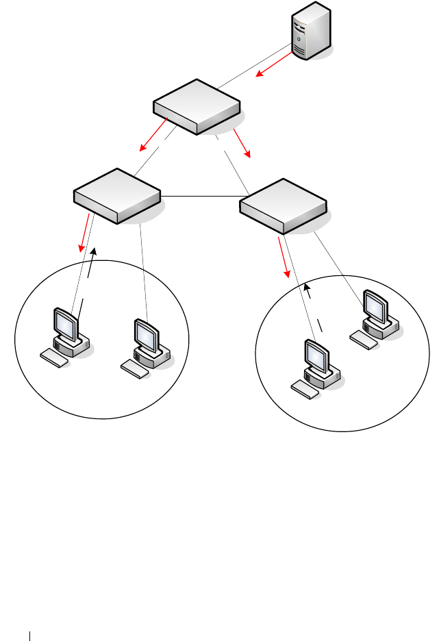
1418 Managing IPv4 and IPv6 Multicast
Figure 43-54. IPv4 Multicast VLAN Routing
In addition to multicast configuration, this example includes commands to
configure STP and OSPF on L3 Switch A. STP is configured on the ports that
connects the switch to other switches. OSPF is configured to route unicast
traffic between the VLANs and PIM is enabled to rout multicast traffic
between the two VLANs. Since IGMP snooping is enabled by default on all
VLANs, no commands to enable it appear in the example below.
To configure Switch A:
1
Create the two VLANs. IGMP/MLD Snooping is disabled globally.
Port 23 Port 24
L3 Switch A
(PIM RP)
``
`
`
Video Server
VLAN 10
Members
VLAN 20
Members
IGMP
Join
L3 Switch B
L3 Switch C
IGMP
Join

Managing IPv4 and IPv6 Multicast 1419
console#configure
console(config)#no ip igmp snooping
console(config)#no ipv6 mld snooping
console(config)#vlan 10,20
console(config-vlan10,20)#exit
2
Configure port 23 and 24 as trunk ports.
console(config)#interface te1/0/23
console(config-if-Te1/0/23)#switchport mode trunk
console(config-if-
Te
1/0/23)#switchport trunk allowed vlan remove 10
console(config-if-Te1/0/23)#exit
console(config)#interface te1/0/24
console(config-if-Te1/0/24)#switchport mode trunk
console(config-if-
Te
1/0/24)#switchport trunk allowed vlan remove 20
console(config-if-Te1/0/24)#exit
3
Enable routing on the switch and configure the OSPF router ID.
console(config)#ip routing
console(config)#router ospf
console(config-router)#router-id 3.3.1.1
console(config-router)#exit
4
Configure VLAN 10 as a VLAN routing interface and specify the OSPF
area. When you assign an IP address to the VLAN, routing is automatically
enabled.
console(config)#interface vlan 10
console(config-if-vlan10)#ip address 192.168.10.4 255.255.255.0
console(config-if-vlan10)#ip ospf area 0
5
Enable IGMPv2 and PIM-SM on the VLAN routing interface.
console(config-if-vlan10)#ip igmp
console(config-if-vlan10)#ip igmp version 2
console(config-if-vlan10)#ip pim
console(config-if-vlan10)#exit
6
Configure VLAN 20 as a VLAN routing interface and specify the OSPF
area.
console(config)#interface vlan 20
console(config-if-vlan20)#ip address 192.168.20.4 255.255.255.0
console(config-if-vlan20)#ip ospf area 0
7
Enable IGMPv2 and PIM-SM on the VLAN routing interface.
console(config-if-vlan20)#ip igmp
console(config-if-vlan10)#ip igmp version 2
console(config-if-vlan20)#ip pim

1420 Managing IPv4 and IPv6 Multicast
console(config-if-vlan20)#exit
8
Globally enable IP multicast, IGMP, and PIM-SM on the switch.
console(config)#ip multicast
console(config)#ip igmp
console(config)#ip pim sparse
9
Configure VLAN 10 as the RP and specify the range of multicast groups
for PIM-SM to control. The 239.9.x.x address is chosen as it is a locally
administered address that maps to MAC addresses that do not conflict
with control plane protocols.
console(config)#ip pim rp-address 192.168.10.4 239.9.0.0 255.255.0.0

Managing IPv4 and IPv6 Multicast 1421
Configuring DVMRP
The following example configures two DVMRP interfaces on the switch to
enable inter-VLAN multicast routing.
To configure the switch:
1
Globally enable IP routing and IP multicast.
console#configure
console(config)#ip routing
console(config)#ip multicast
2
Globally enable IGMP so that this L3 switch can manage group
membership information for its directly-connected hosts. Enabling IGMP
is not required if there are no directly-connected hosts; however, it is
recommended that it be enabled to ensure correct operation of multicast
routing. Disable IGMP/MLD snooping.
console(config)#ip igmp
console(config)#no ip igmp snooping
console(config)#no ipv6 mld snooping
3
Globally enable DVMRP.
console(config)#ip dvmrp
4
Enable DVMRP and IGMP on VLAN routing interfaces 10 and 20.
console(config)#interface vlan 10
console(config-if-vlan10)#ip address 192.168.10.1 255.255.255.0
console(config-if-vlan10)#ip dvmrp
console(config-if-vlan10)#ip igmp
console(config-if-vlan10)#exit
console(config)#interface vlan 20
console(config-if-vlan20)#ip address 192.168.20.1 255.255.255.0
console(config-if-vlan20)#ip dvmrp
console(config-if-vlan20)#ip igmp
console(config-if-vlan20)#exit

1422 Managing IPv4 and IPv6 Multicast

Feature Limitations and Platform Constants 1423
A
Feature Limitations and Platform
Constants
• Table A-1 lists the feature limitations and Table A-2 lists the platform
constants for the Dell Networking switches.
Table A-1. Feature Limitations
Feature N2000 Series N3000 Series N4000 Series
Base software features
Link Dependency
Max Groups
72 72 72
Switching features
Port Mirroring
Number of monitor sessions
Max source ports in a session
1
624
1
624
1
816
RMON 1, 2, 3, 9
Max Ether Stats entries
Max History entries
Max buckets per History entry
Max Alarm entries
Max Event entries
Max Log entries per Event entry
762
270
50
32
32
100
762
270
50
32
32
100
954
270
50
32
32
100
Management ACL (MACAL) Max
Rules
64 64 64
Cut-through mode threshold (bytes) – – 768
VPC
Max Number of VPCs
Max Member ports per VPC
DCPDP UDP Port Number
127
8
50000
127
8
50000
127
8
50000
Routing features

1424 Feature Limitations and Platform Constants
IP Helper Max entries 64 512 512
Metro Ethernet features
Dot1ag
Max number of domains
Max number of MA's per domain
Max number of MA's
Max number of RMEP's
Max number LTR entries
–
–
–
–
–
–
–
–
–
–
8
256
256
512
256
Management features
HTTP Max Sessions
SSL/HTTPS Max Sessions
16
16
16
16
16
16
User management features
User ID configuration
Max number of configured users
Max user name length
Max password length
Max number of IAS users (internal
user database)
8
64
64
100
8
64
64
100
8
64
64
100
Authentication login list
Max Count
Max methods per list
Max name length
5
6
15
5
6
15
5
6
15
Authentication Enable lists
Max Count
Max methods per list
Max name length
5
6
15
5
6
15
5
6
15
Table A-1. Feature Limitations (Continued)
Feature N2000 Series N3000 Series N4000 Series

Feature Limitations and Platform Constants 1425
Authentication HTTP lists
Max Count
Max methods per list
Max name length
1
6
15
1
6
15
1
6
15
Authentication HTTPS lists
Max Count
Max methods per list
Max name length
1
6
15
1
6
15
1
6
15
Authentication Dot1x lists
Max Count
Max methods per list
Max name length
1
6
15
1
6
15
1
6
15
Authorization Exec lists
Max Count
Max methods per list
Max name length
5
4
20
5
4
20
5
4
20
Authorization Command lists
Max Count
Max methods per list
Max name length
5
4
20
5
4
20
5
4
20
Accounting Exec lists
Max Count
Max methods per list
Max name length
5
2
15
5
2
15
5
2
15
Accounting Commands lists
Max Count
Max methods per list
Max name length
5
1
15
5
1
15
5
1
15
Table A-1. Feature Limitations (Continued)
Feature N2000 Series N3000 Series N4000 Series

1426 Feature Limitations and Platform Constants
Login History 50 50 50
QoS features
iSCSI
Max Monitored TCP Ports/IP
Addresses
Max Sessions
Max Connections
16
1024
1024
16
1024
1024
16
252
252
Stacking features
Max physical units per stack 12 12 12
Max physical slots per unit 3 3 3
Max physical ports per slot 52 52 58
Max physical ports per unit 56 56 68
Max physical ports per stack 672 572 816
Max active stack ports per unit 2 2 8
Table A-1. Feature Limitations (Continued)
Feature N2000 Series N3000 Series N4000 Series

Feature Limitations and Platform Constants 1427
Table A-2. Platform Constants
Feature N2000 Series N3000 Series N4000 Series
MAC addresses assigned per system 4 4 4
Reference CPU ARM Cortex
A9
ARM Cortex
A9
NetLogic
XLP308L
Reference CPU speed 1 GHz 1 GHz 1.2 GHz
Reference RAM 1 Gbyte 1 Gbyte 2 Gbyte
DDR3
Reference Flash 256 Mbyte 256 Mbyte 256 Mbyte
Maximum number of remote Telnet
connections
444
Maximum number of remote SSH
connections
555
Number of MAC addresses supported 8192 16384 131072
Maximum Agetime in seconds 1000000 1000000 1000000
Number of VLANs 4096 4096 4096
Maximum VLAN ID 4093 4093 4093
Number of 802.1p traffic classes 7 7 7
IEEE 802.1x
Number of .1x clients per stack
Number of .1x clients per port
2496
64
2496
64
2496
64
Number of LAGs (max. lags/ports/max
dynamic LAG ports per system
128/8/144 128/8/144 128/8/144
Maximum multiple spanning tree
instances
15 15 15
Number of MAC-based VLANs
supported
256 256 256
Number of network buffers 182 182 182
Number of records in log 400 400 400

1428 Feature Limitations and Platform Constants
Static filter entries
Unicast MAC and source port
Multicast MAC and source port
Multicast MAC and destination port
(only)
1
1
1024
1
1
1024
1
1
2048
Number of subnet-based VLANs
supported
128 128 128
Protocol-based VLANs
Max number of groups
Max protocols
128
16
128
16
128
16
Maximum MFDB entries 1024 1024 2048
IGMPv3/MLDv2 Snooping limits
IGMPv3/MLDv2 HW entries when IP
Multicast present
IGMPv3/MLDv2 HW entries when
Routing w/o IP Multicast
IGMPv3/MLDv2 HW entries when
Switching only
1024
4096
8192
1024
4096
8192
512
2048
4096
Jumbo frame support
Max size supported
9216 9216 9216
Number of IP Source Guard stations 1020 1020 378
Number of DHCP snooping bindings 32768 32768 32768
Number of DHCP snooping static entries 1024 1024 1024
LLDP-MED
Number of remote nodes
LLDP Remote Management address
buffers
LLDP Unknown TLV address buffers
LLDP Organizationally Defined TLV
buffers
1296
1396
100
8424
1296
1396
100
8424
1632
1732
100
10608
Table A-2. Platform Constants (Continued)
Feature N2000 Series N3000 Series N4000 Series

Feature Limitations and Platform Constants 1429
Port MAC locking
Dynamic addresses per port
Static addresses per port
600
100
600
100
600
100
sFlow
Number of samplers
Number of pollers
Number of receivers
672
672
8
672
672
8
816
816
8
RADIUS
Max Authentication servers
Max Accounting servers
32
32
32
32
32
32
Number of routes (IPv4/IPv6)
IPv4 only build (–32 due to prefix
length sharing)
IPv4/IPv6 build
IPv4 routes (–32 due to prefix
length sharing)
IPv6 routes
RIP application route scaling
OSPF application route scaling
512
256
128
256
N/A
12288
8160
4096
512
8160
12288
8160
4096
512
8160
Number of static routes (IPv4/IPv6) 256/128 1024/1024 1024/1024
OSPF
Max OSPFv2 LSAs
IPv4-only build
IPv4/IPv6 build
OSPFv2 max neighbors
Max OSPFv3 LSAs
OSPFv2 max neighbors
OSPFv3 max neighbors per interface
N/A
N/A
N/A
N/A
N/A
N/A
37064
24680
400
12488
400
100
36968
24680
400
12488
400
100
Table A-2. Platform Constants (Continued)
Feature N2000 Series N3000 Series N4000 Series

1430 Feature Limitations and Platform Constants
Tu n n e ls
Number of configured v6-over-v4
tunnels
Number of automatic (6to4) tunnels
Number 6to4 next hops
N/A
N/A
N/A
8
1
16
8
1
16
DHCP server
Max number of pools
Total max leases
16
256
16
256
16
256
DNS client
Concurrent requests
Name server entries
Search list entries
Static host entries
Cache entries
Domain search list entries
16
8
6
64
128
32
16
8
6
64
128
32
16
8
6
64
128
32
DHCPv6
Max number of pools
DNS domain names within a pool
DNS server addresses within a pool
Delegated prefix definitions within a
pool
16
5
8
10
16
5
8
10
16
5
8
10
Number of VLAN routing interfaces 128 128 128
Number of ARP entries (Hosts)
Device hardware capacity (v4/v6)
IPv4-only build
IPv4/IPv6 build (v4/v6)
Static v4 ARP entries
1024/512
1024
1024/512
128
16384/8192
6144
4096/1024
128
8192/4086
6144
4096/1024
128
Number of ECMP next hops per route 0 16 4
Number of ECMP groups 0 64 1024
Table A-2. Platform Constants (Continued)
Feature N2000 Series N3000 Series N4000 Series

Feature Limitations and Platform Constants 1431
IP Multicast
Number of IPv4/IPv6 Multicast
Forwarding Entries
IGMP Group Memberships per system
DVMRP Neighbors
PIM-DM Neighbors
PIM-SM Neighbors
PIM-SM Static RP entries
PIM-SM Candidate RP Group Range
entries
PIM-SM SSM range entries
IGMP Sources processed per group per
message
N/A
N/A
N/A
N/A
N/A
N/A
N/A
N/A
N/A
2048
(1536 IPv4,
512 IPv6)
2048 each for
IPv4 and
IPv6
256
256
256
5
20
5
73
1024
(512 IPv4,
256 IPv6)
2048 each for
IPv4 and
IPv6
256
256
256
5
20
5
73
ACL limits
Maximum number of ACLs (any type)
Maximum number of configurable
rules per list.
Maximum ACL Rules per Interface and
Direction (IPv4/L2)
Maximum ACL Rules per Interface and
Direction (IPv6)
Maximum ACL Rules (system-wide)
Maximum VLAN interfaces with ACLs
applied
Maximum ACL Logging Rules (system-
wide)
100
1023
1023 ing.,
1023 egr.
1023 ing.,
509 egr.
3914
24
128
100
1023
2048 ing.,
1023 egr.
1659 ing.,
509 egr.
3914
24
128
100
1023
1023 ing.,
1023 egr.
635 ing.,
509 egr.
3060
24
128
Table A-2. Platform Constants (Continued)
Feature N2000 Series N3000 Series N4000 Series

1432 Feature Limitations and Platform Constants
CoS Device Characteristics
Configurable Queues per port
(stacking/nonstacking)
Configurable Drop Precedence levels
7/8
3
7/8
3
7/8
3
DiffServ Device Limits
Number of queues
(stacking/nonstacking)
Max Rules per Class
Max Instances per Policy
Max Attributes per Instance
Max Service Interfaces
(nonstacking/stacking)
Max table entries
Class Table
Class Rule Table
Policy Table
Policy Instance Table
Policy Attribute Table
Max Nested Class Reference Chain
Rule Count
7/8
13
12
3
184/800
32
416
64
768
2304
26
7/8
13
12
3
184/800
32
416
64
768
2304
26
7/8
13
12
3
196/944
32
416
64
768
2304
26
Datacenter Device Limits
PFC number of lossless prioirities
ETS number of traffic class groups
N/A
N/A
N/A
N/A
2
3
AutoVoIP number of voice calls 16 16 16
Voice VLAN number of devices 672 672 816
Table A-2. Platform Constants (Continued)
Feature N2000 Series N3000 Series N4000 Series
System Process Definitions 1433
B
System Process Definitions
The following process/thread definitions are intended to assist the end user in
troubleshooting switch issues. Only the most often seen threads/processes are
listed here. Other processes or threads may be seen occasionally but are not a
cause for concern.
Table B-1. System Process Definitions
Name Task Summary
aclClusterTask
aclEventTask
aclLogTask
ACL tasks
ARP Timer ARP tasks
autoInstTask Auto Install task - USB, etc.
bcmATP-RX
bcmATP-TX
BCM system task: Acknowledged Transport Protocol
bcmCNTR.0 BCM system task: SDK Statistics collection
bcmDISC BCM system task: SDK Discovery task
bcmDPC BCM system task: SDK DPC task
bcmL2X.0 BCM system task: SDK L2 SOC shadow table
maintenance
bcmLINK.0 BCM system task: SDK Physical link status monitor
bcmNHOP BCM system task: SDK transport Next Hop task
bcmRLINK BCM system task:SDK Remote registration last
bcmRPC BCM system task:SDK Remote registration last
bcmRX BCM system task: SDK Control plane packet
receiver/dispatcher
bcmTUNQ BCM system task: SDK transport queueing task
bcmTX BCM system task: SDK Control plane packet
transmitter
1434 System Process Definitions
bcmXGS3AsyncTask BCM system task: SDK XGX3 hw task
BootP Boot Loader
boxs Req Box Services Request (temperature, power, fan)
boxs Resp Box Services Response (temperature, power, fan)
boxs Timer Box Services Response (temperature, power, fan)
cdaFftpTask Code Distribution Administrator FTP task
cdaStatusTask Code Distribution Administrator Status task
cdaUpdateTask Code Distribution Administrator Update task
cliWebIORedirectTask CLI Web IO Redirection Task
cmgrInsertTask Card Manager Insertion Handler
cmgrTask Card Manager Status (built-in and plug-in card
configuration processing)
Cnfgr_Thread Configurator (startup manager)
CP Wired If Captive Portal
cpuUtilMonitorTask CPU Utilities monitor
DapiDebugTask Device API debug processing
DHCP Server Processing
Tas k
DHCP snoop
dhcpsPingTask
DHCPv4 Client Task
DHCPv6 Client Task
DHCPv6 Server Task
DHCP Tasks
dnsRxTask
dnsTask
DNS tasks
dosTask Denial of Service task
dot1qTask VLAN routing task
Table B-1. System Process Definitions (Continued)
Name Task Summary
System Process Definitions 1435
Dot1s transport task
dot1s_helper_task
dot1s_task
dot1s_timer_task
Spanning Tree tasks
dot1xTask
dot1xTimerTask
802.1x authentication tasks
dot3ad_core_task
dot3ad_core_ac_task
dot3ad_helper_task
dot3ad_timer_task
Link aggregationt tasks
dtlAddrTask
dtlTask
Device Transform Layer - Silicon Integration Layer
dvmrpMapTask DVMRP Mapping Layer
Dynamic ARP Inspection Dynamic ARP Inspection task
EDB Entity MIB Processing task
EDB Trap Entity MIB Trap task
emWeb UI processing task
envMonTask Environment Monitor (fans, power supplies,
temperature, …)
fdbTask Forwarding Data Base Manager
fftpTask FTP processing
gccp_t GARP Central Control Point task (dot 1d)
Table B-1. System Process Definitions (Continued)
Name Task Summary

1436 System Process Definitions
hapiBpduTxTask
hapiL2AsyncTask
hapiL2FlushTask
hapiL3AsyncTask
hapiLinkStatusTask
hapiMcAsyncTask
hapiRxTask
hapiTxTask
High Level API - SDK Integration Layer
hpcBroadRpcTask SDK Remote messaging task.
ip6MapExceptionDataTask
ip6MapLocalDataTask
ip6MapNbrDiscTask
ip6MapProcessingTask
ip6MapRadvdTask
ipcom_sysl
IpHelperTask
ipMapForwardingTask
ipMapProcessingTask
ipnetd
IP Stack
iscsiTask ISCSI task
isdpTask ISDP task
lldpTask LLDP task
LOG System LOG processing
LOGC System LOG processing
MAC Age Task MAC address table aging
MAC Send Task MAC address table learning
macalTask Management ACL packet processing
Table B-1. System Process Definitions (Continued)
Name Task Summary
System Process Definitions 1437
mcastMapTask
mgmdMapTask
Multicast Mapping Tasks
mvrTask MVR Message Handler
nim_t Network Interface Manager
osapiMonTask System Task Monitor
osapiTimer Application timer service
osapiWdTask Hardware watchdog timer service
OSPF mapping Task
OSPF Proto
OSPFV3 mapping Task
OSPFV3 recvmsg Task
OSPFv3 Proto
OSPF tasks
pimdmMapTask PIMDM task
pimsmMapTask PIMSM task
pingAsync Ping response processing
pktRcvrTask Multicast control plane packet receiver/dispatch
pmlTask Port MAC Locking management task
portAggTask Port Aggregator task
radius_rx_task
radius_task
RADIUS server tasks
ripMapProcessingTask RIP Mapping layer
RLIM cnfgr task VRRP configuration
RLIM task VRRP message processing
RMONTask RMON Statistics Collection
serialInput Serial Input task
sFlowTask sFlow task
SimAddrConflictTask System Interface Manager Address Conflict Task
Table B-1. System Process Definitions (Continued)
Name Task Summary
1438 System Process Definitions
simPts_task System Interface Manager (time zone, system name,
service port config, file transfers, ...)
SNMPCTTask
SNMPSaveCfgTask
SNMPTask
SNMPTrapTask
SNMP Tasks
snoopTask IGMP/MLD Snooping packet processing
SNTP
SNTPC
SNTP tasks
spmTask Stack port manager - stacking control plane packet
processing
sshdEvTask SSH task
ssltTask SSL task
Stk Mgr Task Stack Manager Task
tacacs_rx_task
tacacs_task
TACACS tasks
tArpCallback
tArpReissue
ARP tasks
tArpTimerExp ARP Timer Expiry
tCpktSvc NSF Processing
tCptvPrtl Captive portal control plane processing
tDhcp6sTask
tDhcpsTask
DHCP Tasks
tEmWeb Web page server
tErfTask VxWorks Task
tExcTask VxWorks Executive
TimeRange Processing Task ACL Time Ranges
tIomEvtMon CMC Communication
Table B-1. System Process Definitions (Continued)
Name Task Summary

System Process Definitions 1439
tJobTask VxWorks Task
tL7Timer0 System Timer
tLogTask System LOG processing
tNet0 VxWorks Network driver
TransferTask TFTP Processing
trapTask Trap handl er
tRipTask RIP Routing
tRtrDiscProcessingTask Router Discovery packet processing
tTffsPTask VxWorks True Flash File System driver
tXbdService VxWorks flash file system load leveler
usbFlashDriveTask USB Flash driver processing
umCfgUpdateTask
umWorkerTask
unitMgrTask
Stack Management: Unit Manager tasks
USL Worker Task USL Message processing (primarily MAC address table
CLI commands)
UtilTask Mgmt. UI login/logout processing
voipTask Voice Over IP
VRRPdaemon VRRP task
Table B-1. System Process Definitions (Continued)
Name Task Summary

1440 System Process Definitions

Index 1441
Index
Numerics
10GBase-T copper uplink
module, 119
802.1p
see CoS queuing
A
AAA, 207
access lines, 239
access profiles, 63
accounting, 214
ACLs
Auto-Voip usage, 1332
binding configuration, 609
CLI configuration, 612
configuration steps, 591
defined, 583
examples, 628
iSCSI usage, 461
limitations, 587
logging, 586
preventing false matches, 591
supported types, 67
web-based configuration, 599
ACLs. See also IP ACL, IPv6
ACL, and MAC ACL.
active images, 368
address table. See MAC address
table.
administrative profiles, 213
defaults, 240
RADIUS authorization, 232
TACACS+ authorization, 228
alternate store and forward, 71
Amber, 98, 110-111, 122-123
ARP, 82
dynamic ARP inspection, 68
ARP inspection. see DAI.
ARP table
configuring (CLI), 1080
configuring (web), 1070
authentication, 211
examples, 215
tiered, 578
authentication key, SNTP, 294
Authentication Manager, 578
authentication profiles, 63
authentication server filter
assignments, 535
authorization, 212
administrative profiles, 213
examples, 227
RADIUS, 231
auto configuration
auto save, 398

1442 Index
CLI configuration, 402
defaults, 400
defined, 389
DHCP, 405
configuration file, 395
image, 395
IP address, obtaining, 394
example, 403
files
setup file, 392
USB, 390
files, managing, 398
IP address lookup, 391
MAC address lookup, 391
stopping, 398
using a USB device, 403
using DHCP, 393
web-based configuration, 401
auto image download
DHCP, 405
USB, 403
auto install, 59
auto install. See auto
configuration.
auto negotiation, 72
auto save feature, 398
auto VoIP
CLI configuration, 1335
defaults, 1332
understanding, 1331
web-based configuration, 1333
auto-provisioning, iSCSI, 463
Auto-VoIP
and ACLs, 1332
B
back pressure, 72
banner, CLI, 315
baud rate, 120
BOOTP/DHCP relay agent, 83
BPDU
filtering, 80, 722
flooding, 722
guard, 80
protection, 724
bridge multicast address groups,
configuring, 818
bridge multicast group
table, 817
bridge table, 1015
broadcast storm control. See
storm control.
C
cable test, 243, 254
and green mode, 254, 484
captive portal, 65
CLI configuration, 568
client management, 573
configuring, 574
customizing pages, 546
defaults, 548
defined, 543
dependencies, 544
design considerations, 545
example, 574

Index 1443
localization, 547
understanding, 543, 546
user logout mode, 547
users, RADIUS server, 558
web-based configuration, 550
cards
configuration, 301
supported, 303
CDP, interoperability through
ISDP, 60
certificates, 363
CFM, 859
checkpointing, 179
Cisco protocol filtering, 76
CLI
accessing the switch, 135
banner, 279
command completion, 140
command modes, 137
command prompt, 281
error messages, 141
negating commands, 140
CLI banner, configuring, 315
clock, system, 292
command modes, CLI, 137
commands
abbreviated, 140
entering, 139
history buffer, 141
Compellent storage arrays, 464
configuration file
defined, 362
DHCP auto configuration, 395
downloading, 365
editing, 365
SNMP, 366
USB auto configuration, 392
USB device, 386
configuration scripts, 365, 384
configuration, saving the, 366
Configuring, 1037
connectivity fault management.
See IEEE 802.1ag.
console port
connecting to, 135
description, 120
Console Port Description, 94
copy, files, 374
CoS
and iSCSI, 460
and PFC, 985
CLI configuration, 1324
configuration example, 1328
defaults, 1316
defined, 1313
queue management
methods, 1315
traffic queues, 1315
traffic shaping, 1314
trusted mode ports, 1314
untrusted mode ports, 1314
web-based configuration, 1318
CoS queuing

1444 Index
D
DAI
defaults, 885
optional features, 884
purpose, 885
understanding, 884
data center
and DHCP snooping, 910
and NSF, 199
SDM template, 281
data center bridging
exchange, 75
Data Center Bridging Exchange
protocol, 992
date, setting, 311
daylight saving time, 280
DCBX
and iSCSI, 464
DCBx, 992
default gateway,
configuring, 149, 156
default VLAN, 163
DHCP client, 161
IP address configuration, 153
denial of service, 64, 582
device discovery protocols, 762
device view, 132
DHCP
understanding, 1037
DHCP auto configuration
dependencies, 399
enabling, 405
monitoring, 398
process, 393
DHCP client, 1041
default VLAN, 161
OOB port, 161
DHCP relay, 76, 1041
CLI configuration, 1105
defaults, 1093
example, 1109
layer 2, 1088
layer 3, 1087
understanding, 1087
VLAN, 1089
web-based configuration, 1094
DHCP server, 57
address pool configuration, 1058
CLI configuration, 1054
defaults, 1042
examples, 1058
leases, 162
options, 1038
web-based configuration, 1043
DHCP snooping, 68, 1041
bindings database, 881
defaults, 885
example, 910
logging, 882
purpose, 885
understanding, 880
VLANs, 882
DHCPv6
client, 1250-1251
defined, 85

Index 1445
examples, 1281
pool, 1266
prefix delegation, 1266
relay agent, configuring, 1283
relay agent, understanding, 1266
stateless server
configuring, 1281
stateless server,
understanding, 1266
understanding, 1265
dhcpv6, 1265
DHCPv6 pool
stateless server support, 1277
DHCPv6 relay
CLI configuration, 1277
defaults, 1267
web-based configuration, 1268
DHCPv6 server
CLI configuration, 1277
prefix delegation, 1282
web-based configuration, 1268
DHCPv6 server relay
defaults, 1267
DiffServ
and 802.1X, 511
and RADIUS, 511
and switch role, 1286
CLI configuration, 1300
defaults, 1287
elements, 1286
example, 1307
understanding, 1285
VoIP, 1 3 1 0
web-based configuration, 1288
diffServ, 86
discovery, device, 761
document conventions, 52
domain name server, 157
domain name, default, 158
Dot1x, 66
dot1x
authentication, 211
double-VLAN tagging, 651
downloading files, 370
DSCP value and iSCSI, 461
dual images, 58
dual IPv4 and IPv6 template, 281
Duplex mode, 94, 104
DVMRP, 89
defaults, 1355
example, 1421
understanding, 1353
web-based configuration, 1394
when to use, 1354
dynamic ARP inspection, 68
dynamic LAGs, 929
dynamic VLAN creation, 534
E
EAP statistics, 422
email alert
statistics, 266
email alerting, 276

1446 Index
log messages, 272
enable authentication, 211
energy detect mode, 69, 478
Energy Efficient Ethernet, 69
energy savings, port, 478
enhanced transmission
selection, 75, 999
EqualLogic and iSCSI, 463
error messages, CLI, 141
EtherType numbers,
common, 592
exec authorization, 212
expansion slots, 284
F
failover, 62
failover, stacking, 179
false matches, ACL, 591
FCoE
configuring CoS queues for, 1329
file management
CLI, 375
considerations, 364
copying, 374
purpose, 361
supported protocols, 363
web-based, 367
file system, 367
files
and stacking, 366
downloading to the switch, 364
types, 359
uploading from the switch, 364
filter assignments,
authentication server, 535
filter, DiffServ, 511
firmware
managing, 364
updating the stack, 177
upgrade example, 381
firmware synchronization,
stacking, 177
Flashing Green, 99, 112, 124
flow control
configuring, 798
default, 790, 984
port-based, 791
understanding, 788
flow-based mirroring, 1299
forwarding database, 1015
and port security, 883
G
GARP, 810
GARP and GVRP, 78
GMRP, 810
green Ethernet, 478, 483
green features, 69
guest VLAN, 508

Index 1447
VLAN
guest, 533
GVRP, 650
statistics, 421
H
Hardware description, 91, 102,
115
head of line blocking
prevention, 71
health, system, 251
help, accessing web-based, 139
hierarchical authentication, 578
host name, 279
host name mapping, 148
I
IAS
database, 518
understanding, 511
users, 525
icons, web-based interface, 131
identification
asset tag, 279
system contact, 279
system location, 279
system name, 279
IDSP
defaults, 763
IEEE 802.1ag
administrator, 863
carrier network, 860
configuration (CLI), 873
configuration (web), 865
defaults, 864
defining domains and ports, 863
example, 876
MEPs and MIPs, 861
troubleshooting tasks, 864
understanding, 859
IEEE 802.1d, 79
IEEE 802.1Q, 78
IEEE 802.1Qaz, 993
IEEE 802.1X, 66
and DiffServ, 511
authentication, 66
configuring, 525
defined, 504
monitor mode, 66, 509, 522
port authentication, 520
port states, 505
RADIUS-assigned VLANs, 523
reauthenticating ports, 514
VLAN assignment, 507
IEEE 802.1x
authentication, 211
IEEE 802.3x. See flow control.
IGMP, 89
defaults, 1355
understanding, 1341
web-based configuration, 1364
IGMP proxy, 89, 1341

1448 Index
IGMP snooping, 87
defaults, 814
querier, 88
querier, defined, 807
understanding, 805
image
activating, 375
auto configuration, 395
auto install, 392
considerations, 364
defined, 359
downloading, 375
management, CLI, 375
management, web-based, 367
purpose, 361
in-band management, 149
interface, 1021
configuration mode, 481
loopback, 1022
OOB, 152
routing, 1021
CLI configuration, 1033
web configuration, 1027
routing defaults, 1026
supported types, 481
tunnel, 1023
internal authentication server,
see IAS
IP ACL
configuration, 599
defined, 585
IP address
configuring, 149
default, 151
default VLAN, 154, 163
OOB port, 163
IP helper, 83, 1089
IP multicast traffic
layer 2, 804
layer 3, 1338
IP protocol numbers,
common, 592
IP routing
CLI configuration, 1079
defaults, 1065
example, 1084
understanding, 1063
web-based configuration, 1067
IP source guard, 67
IPSG
and port security, 883
example, 912
purpose, 885
understanding, 883
IPv4 and IPv6 networks,
interconnecting, 1187
IPv4 multicast
web-based configuration, 1357
IPv4 routing template, 281
IPv6
compared to IPv4, 1242
DHCP client, 1250-1251
DHCPv6, 85
OSPFv3, 85
routes, 85
static reject and discard
routes, 1263

Index 1449
tunnel, 84
IPv6 ACL configuration, 606
IPv6 interface
configuring, 1242
IPv6 management, 58
IPv6 multicast
web-based configuration, 1363
IPv6 routing
CLI configuration, 1256
defaults, 1243
features, 85
understanding, 1241
web-based configuration, 1245
IRDP, configuring, 1081
iSCSI
ACL usage, 461
and Compellent storage
arrays, 464
and CoS, 460
and DCBX, 464
and Dell EqualLogic arrays, 463
assigning flows, 460
CLI configuration, 471
defaults, 466
examples, 473
flow detection, 460
information tracking, 462
servers and a disk array, 473
understanding, 459
using, 460
web-based configuration, 467
ISDP
and CDP, 60
CLI configuration, 777
configuring, 778
enabling, 778
example, 782
understanding, 761
web-based configuration, 765
J
jumbo frames, 71
L
LACP, 81
adding a LAG port, 922
CLI configuration, 927
web-based configuration, 920
LAG
and STP, 916
CLI configuration, 925
defaults, 917
examples, 929
guidelines, configuration, 916
interaction with other
features, 916
LACP, 81
purpose, 914
static and dynamic, 914
statistics, 436
threshold, minimum links, 925
understanding, 913
web-based configuration, 918
LAG hashing, 915
languages, captive portal, 547

1450 Index
LED
100/1000/10000Base-T port, 97,
109, 121
port, 119
SFP port, 97, 109, 121
system, 98, 110, 122
link aggregation group. See LAG.
link dependencies
CLI configuration, 497-498
creating, 489
example, 501
scenarios, 480
understanding, 479
web configuration, 489
link local protocol filtering, see
LLPF
LLDP
CLI configuration, 777
defaults, 763
example, 783
understanding, 761
web-based configuration, 765
LLDP-MED
and voice VLANs, 654
configuring, 781
understanding, 762
viewing information, 782
LLPF
defaults, 790, 984
example, 801
understanding, 789
localization, captive portal, 547
locating the switch, 133
locator LED
enabling, 133, 267
log messages, 57
log server, remote, 260
logging
ACL, 586
CLI configuration, 267
considerations, 247
defaults, 248
destination for log messages, 244
example, 274
file, 259
log message format, 246
operation logs, 245
severity levels, 245
system startup logs, 245
trap log, 343
web-based configuration, 249
loopback, 84
loopback interface
configuring, 1035
purpose, 1025
understanding, 1022
low-power idle, 483
LSA, OSPF, 1113
M
MAC ACL
understanding, 584
MAC address table
and port security, 883
contents, 1016

Index 1451
defaults, 1016
defined, 1015
dynamic, 1019
managing, CLI, 1020
populating, 1015
stacking, 1016
web-based management, 1017
MAC multicast support, 87
MAC port locking, 540
MAC-based 802.1X
authentication
understanding, 506
MAC-based VLAN, 648
mail server
adding, 263
configuring, 271
email alert, 262
management
access control using
RADIUS, 232
access control using
TACACS+, 237
management, in-band and
out-of-band, 149
MD5, 283
MDI/MDIX, auto, 72
MEP, configuring, 874
MIB, SNMP, 323
Microsoft Network Load
Balancing, 1354
mirror, ACL, 585
mirroring, flow-based, 1299
MLAG, 932
MLD, 90
defaults, 1355
understanding, 1342
web-based configuration, 1373
MLD snooping, 88
defaults, 814, 885
understanding, 807
VLAN configuration, 849
mode
interface configuration, 481
monitor mode, IEEE
802.1X, 509
monitoring system
information, 243
MSTP
example, 753
operation in the network, 717
support, 79
understanding, 715
MTU, configuring, 497
MTU, management
interface, 150
Multicast
VLAN registration, 88
multicast
DVMRP, 89
IGMP, 89
IGMP proxy, 89
IGMP snooping, 87
IPv4, 1357
layer 2, 87
configuring (CLI), 846

1452 Index
configuring (web), 816
defaults, 814
understanding, 803
when to use, 809
layer 3, 89
CLI configuration, 1399
defaults, 1355
examples, 1417
understanding, 1337
when to use, 1340
MAC layer, 87
MLD snooping, 88
protocols
roles, 1339-1340
VLAN Routing with IGMP and
PIM-SM, 1417
multicast bridging, 804, 846
multicast protocols,
supported, 1339
multicast routing table, 1341
multicast snooping, 854
multicast VLAN
registration, 808
MVR
adding an interface, 838
N
N2000 back panel, 95
N2000 Port Description, 91
N3000 back panel, 106
N3000 Port Description, 102
netinfo, 147
network information
CLI configuration, 161
default, 151
defined, 147
example, 166
purpose, 148
web-based configuration, 152
network pool, DHCP, 1046
nonstop forwarding, see NSF
NSF
and DHCP snooping, 201
and routed access, 204
and the storage access
network, 202
and VoIP, 200
in the data center, 199
network design
considerations, 181
understanding, 178
O
OAM, 859
OOB port, 119-120, 152
DHCP client, 161
OpenManage Switch
Administrator, about, 127
optical transceiver
diagnostics, 255
OSPF, 82
areas, 1112
border router, 1177
CLI configuration, 1155

Index 1453
defaults, 1120
difference from OSPFv3, 1113
examples, 1177
flood blocking, 1118, 1195
LSA pacing, 1117
NSSA, 1180
static area range cost, 1116, 1190
stub area, 1180
stub routers, 1114
topology, 1112
trap flags, 341
understanding, 1112
web-based configuration, 1122
OSPFv3, 85
CLI configuration, 1167
difference from OSPF, 1113
global settings, 1167
interface settings, 1169
NSSA, 1180
stub area, 1180
trap flags, 342
web-based configuration, 1138
out of band port, IP address, 163
out-of-band management, 149
P
password
protecting management
access, 63
strong, 63
PFC, 985
PIM
defaults, 1355
IPv4 web-based
configuration, 1382
IPv6 web-based
configuration, 1382
PIM-DM, using, 1352
PIM-SM, using, 1343
SSM range, 1390
understanding, 1343
plug-in modules
configuring, 284
PoE+, 285, 313
policy based routing (PBR), 594
port
access control, 516
characteristics, 477
configuration examples, 500
configuring multiple, 487
defaults, 485
defined, 477
device view features, 132
example, 500
LEDs, 119
locking, 540
OOB, 119-120
power saving, 483
protected, 68, 794, 799
statistics, 435
traffic control, 787, 983
USB, 119
port characteristics
CLI configuration, 496
web-based configuration, 486
port control, 515
port fast, STP, 722

1454 Index
Port LEDs, 97, 109, 121
port mirroring
configuring, 437
mode, enabling, 412
understanding, 411
port security
configuring, 542
MAC-based, 66
understanding, 539
port-based flow control, 791
port-based traffic control, 787
CLI configuration, 798, 992
web-based configuration, 791
port-based VLAN, 648
port-channel. See LAG.
port-MAC locking, 66
see port security
power supplies, 120
power utilization reporting, 69
power, per-port saving
modes, 483
priority flow control, 985
priority-based flow control, 74,
985
private VLAN edge, 68
private VLANs, 654, 711
protected port
defined, 789
example, 801
protocol filtering, Cisco, 76
protocol-based VLAN, 648
Q
QoS
CoS queuing
diffserv, 86
QSFP module, 118
queues, CoS, 1315
R
RADIUS, 64
and DiffServ, 511
authentication, 225
authorization, 231-232
for management access
control, 232
supported attributes, 234
understanding, 232
RAM log, 258
real time clock, 280
redirect, ACL, 585
relay agent, DHCPv6, 1266
relay, DHCP, 1087
remote logging, 270
RIP, 83
CLI configuration, 1209
defaults, 1203
determining route
information, 1201
example, 1213
supported versions, 1202
understanding, 1201
web-based configuration, 1204

Index 1455
RMON, 60
CLI management, 439
defaults, 414
example, 449
understanding, 410
web-based configuration, 414
router discovery, 1081
router discovery protocol, 83
router, OSPF, 1113
routes
IPv4, 1077
IPv6, 1255
selecting, 1113
Routing
table, 83
routing
defaults (IPv4), 1065
defaults (IPv6), 1243
example, 1084
IPv4, CLI configuration, 1079
IPv4, web-based
configuration, 1067
IPv6, CLI configuration, 1256
IPv6, web-based
configuration, 1245
understanding, 1063
routing interfaces
CLI configuration, 1033
defaults, 1026
understanding, 1021
using, 1024
web-based configuration, 1027
routing table
best routes, 1074
configuring, 1082
IPv6, 1260, 1262
RSPAN, 73, 411
RSTP
understanding, 715
RSTP-PV, 724
running-config, saving, 366
S
save, system settings, 366
SDM template
configuration guidelines, 283
managing, 309
understanding, 281
SDM templates, 58
security
port, defined, 539
port-based
CLI configuration, 520
defaults, 511, 539
examples, 525
web-based
configuration, 512
setup file format, auto
configuration, 392
sFlow, 59
CLI management, 439
defaults, 414
example, 447
understanding, 407
web-based management, 414

1456 Index
SFP port LEDs, 97, 109, 121
SFP+ module, 118
SFTP, managing files, 380
slots, 284
SNMP
CLI configuration, 345
defaults, 325
examples, 354
MIB, 323
purpose, 325
traps, 324
understanding, 323
uploading files, 366
web-based configuration, 327
SNMPv1 example, 354
SNMPv2 example, 354
SNMPv3
engine ID, 345
example, 355
SNTP
authentication, 309
authentication key, 294
example, 319
server, 309
server configuration, 296
understanding, 283
software image, 359
spanning tree. See STP.
split horizon, 1202
SSH files, 363
SSH/SSL, 64
SSL files, 363
SSM range, 1390
stacking
adding a switch, 176
and NSF, 62
CLI configuration, 192
defaults, 182
defined, 171
design consideration, 181
failover, 62
failover, example, 195
failover, initiating, 179
features, 61
file management, 366
firmware synchronization, 177
firmware update, 177
MAC address table, 1016
MAC addresses, 181
NSF usage scenario, 195
preconfiguration, 197
purpose, 182
removing a switch, 177
standby, 178
switch compatibility, 174
web-based configuration, 184
static reject route, 1064
statistics
IPv6, 1248
statistics, Etherlike, 420
storage arrays and iSCSI, 463
storage arrays, Compellent, 464
storm control
configuring, 798

Index 1457
default, 790, 984
example, 801
understanding, 788
STP
and LAGs, 916
classic, 715
CLI configuration, 746
defaults, 735
defined, 715
examples, 751
loop guard, 723
MSTP, 79
optional features, 722
port fast, 722
port settings, 79
root guard, 723
RSTP, 79
understanding, 716
web-based configuration, 736
STP-PV, 724
subnet mask, configuring, 149
subnet-based VLAN, 648
summer time, 280
switchport modes, VLAN, 648
switchport statistics, web
view, 425
system health, monitoring, 249
system information
CLI configuration, 307
default, 286
defined, 279
example, 315
purpose, 281
web-based configuration, 287
system LEDs, 119
system time, 283
T
TACACS+, 63
authentication, 217
authorization, 227-228
management access control, 237
supported attributes, 238
understanding, 237
tagging, VLAN, 649
Telnet
configuration options, 64
connecting to the switch, 136
TFTP, image download, 375
tiered authentication, 578
time domain reflectometry, 254
time management, 56
time range, 626
time zone, 300
time, setting the system, 321
time-based ACLs, 586
traffic class queue, 460
traffic control
port based, 787, 983
traffic inspection, 879
traffic monitoring, 407
traffic snooping, 879

1458 Index
traps
OSPF, 341
trunk port
and 802.1X authentication, 533,
535
trunking, 683
tunnel, 84
tunnel interfaces, 1023
U
UDP relay, 83, 1089
uploading files, 372
USB auto configuration
example, 403
files, 390-391
understanding, 390
USB flash drive, example, 386
USB port, 119
user security model, SNMP, 324
users
authenticated, 515
captive portal, 556
IAS database, 511
USM, 324
V
Ventilation System, 96
ventilation system, 121
virtual link, OSPF, 1184
VLAN, 916
authenticated and
unauthenticated, 507
CLI configuration, 682
defaults, 661
double, 78
double-VLAN tagging, 651
dynamic, 508
example, 701, 706
guest, 78, 508, 534
IP subnet-based, 77
MAC-based, 77, 648
port-based, 77, 648
private, 654, 711
protocol-based, 77, 648
RADIUS-assigned, 534
routing, 82
routing interfaces, 1021, 1033
static, 648
support, 77
switchport modes, 648
trunk port, 683
understanding, 645
voice, 78, 653
voice traffic, 653
voice, example, 710
voice, understanding, 652
web-based configuration, 663
VLAN membership,
defining, 663
VLAN priority tag and
iSCSI, 461
VLAN routing, 1021, 1024
VLAN tagging, 649

Index 1459
VLANs
dynamically created, 534
RADIUS-assigned, 534
voice traffic, identifying, 653
voice VLAN, 653
and LLDP-MED, 654
example, 710
understanding, 652
VoIP, 86
VoIP and DiffServ, 1310
VoIP, auto, 1331
VRRP, 84
accept mode, 1219
CLI configuration, 1230
defaults, 1221
example, 1232
interface tracking, 1219
load sharing example, 1232
preemption, 1218
route and interface tracking
example, 1236
route tracking, 1219
router priority, 1218
understanding, 1217
web-based configuration, 1222
W
web-based configuration, 128
web-based interface,
understanding, 129
writing to memory, 366

Index 1460
