Dell Idrac6 Enterprise For Blade Servers Version 2 0 Owners Manual 2.0 User Guide
2014-11-13
: Dell Dell-Idrac6-Enterprise-For-Blade-Servers-Version-2-0-Owners-Manual-118298 dell-idrac6-enterprise-for-blade-servers-version-2-0-owners-manual-118298 dell pdf
Open the PDF directly: View PDF ![]() .
.
Page Count: 432 [warning: Documents this large are best viewed by clicking the View PDF Link!]
- User Guide
- Contents
- iDRAC6 Enterprise Overview
- Configuring iDRAC6 Enterprise
- Before You Begin
- Interfaces for Configuring iDRAC6
- Configuration Tasks
- Configure the Management Station
- Configure iDRAC6 Networking
- Configure iDRAC6 Users
- Configure Active Directory
- Configure IP Filtering and IP Blocking
- Configure Platform Events
- Enabling or Disabling Local Configuration Access
- Configure iDRAC6 Services
- Configure Secure Sockets Layer (SSL)
- Configure Virtual Media
- Configure a VFlash Media Card
- Install the Managed Server Software
- Configure the Managed Server for the Last Crash Screen Feature
- Configuring Networking Using the CMC Web Interface
- Viewing FlexAddress Mezzanine Card Fabric Connections
- Updating iDRAC6 Firmware
- Updating the USC Repair Package
- Configuring iDRAC6 For Use With IT Assistant
- Configuring the Management Station
- Configuring the Managed Server
- Configuring iDRAC6 Enterprise Using the Web Interface
- Accessing the Web Interface
- Configuring the iDRAC6 NIC
- Configuring Platform Events
- Configuring IPMI Over LAN
- Adding and Configuring iDRAC6 Users
- Securing iDRAC6 Communications Using SSL and Digital Certificates
- Configuring and Managing Active Directory Certificates
- Enabling or Disabling Local Configuration Access
- Configuring iDRAC6 Services
- Updating iDRAC6 Firmware
- Using iDRAC6 With Microsoft Active Directory
- Prerequisites for Enabling Active Directory Authentication for iDRAC6
- Supported Active Directory Authentication Mechanisms
- Extended Schema Active Directory Overview
- Extending the Active Directory Schema
- Active Directory Schema Extensions
- Overview of the iDRAC6 Schema Extensions
- Active Directory Object Overview
- Accumulating Privileges Using Extended Schema
- Configuring Extended Schema Active Directory to Access iDRAC6
- Installing the Dell Extension to the Active Directory Users and Computers Snap-In
- Adding iDRAC6 Users and Privileges to Active Directory
- Configuring Active Directory With Extended Schema Using the iDRAC6 Web-Based Interface
- Configuring Active Directory With Extended Schema Using RACADM
- Standard Schema Active Directory Overview
- Testing Your Configurations
- Enabling SSL on a Domain Controller
- Using Active Directory to Log In to iDRAC6
- Frequently Asked Questions
- Viewing the Configuration and Health of the Managed Server
- Power Monitoring and Power Management
- Configuring and Using Serial Over LAN
- Using GUI Console Redirection
- Configuring a VFlash Media Card for Use With iDRAC6
- Configuring and Using Virtual Media
- Using the Local RACADM Command Line Interface
- Using the RACADM Command
- RACADM Subcommands
- Using the RACADM Utility to Configure iDRAC6
- Displaying Current iDRAC6 Settings
- Managing iDRAC6 Users with RACADM
- Adding an iDRAC6 User
- Enabling an iDRAC6 User With Permissions
- Removing an iDRAC6 User
- Testing E-mail Alerting
- Testing the iDRAC6 SNMP Trap Alert Feature
- Configuring iDRAC6 Network Properties
- Configuring IPMI Over LAN
- Configuring PEF
- Configuring PET
- Configuring IP Filtering (IP Range)
- Configuring IP Filtering
- Configuring IP Blocking
- Configuring iDRAC6 Telnet and SSH Services Using Local RACADM
- Using an iDRAC6 Configuration File
- Configuring Multiple iDRACs
- Using iDRAC6 Enterprise SM-CLP Command Line Interface
- Deploying Your Operating System Using iVMCLI
- Using the iDRAC6 Configuration Utility
- Recovering and Troubleshooting the Managed Server
- Safety First-For You and Your System
- Trouble Indicators
- Problem Solving Tools
- Checking the System Health
- Checking the System Event Log (SEL)
- Checking the Post Codes
- Viewing the Last System Crash Screen
- Viewing the Most Recent Boot Sequences
- Checking the Server Status Screen for Error Messages
- Viewing the iDRAC6 Log
- Viewing System Information
- Identifying the Managed Server in the Chassis
- Using the Diagnostics Console
- Managing Power on a Remote System
- Troubleshooting and Frequently Asked Questions
- RACADM Subcommand Overview
- iDRAC6 Enterprise Property Database Group and Object Definitions
- Displayable Characters
- idRacInfo
- cfgOobSnmp
- cfgLanNetworking
- cfgDNSDomainNameFromDHCP (Read/Write)
- cfgDNSDomainName (Read/Write)
- cfgDNSRacName (Read/Write)
- cfgDNSRegisterRac (Read/Write)
- cfgDNSServersFromDHCP (Read/Write)
- cfgDNSServer1 (Read/Write)
- cfgDNSServer2 (Read/Write)
- cfgNicEnable (Read/Write)
- cfgNicIpAddress (Read/Write)
- cfgNicNetmask (Read/Write)
- cfgNicGateway (Read/Write)
- cfgNicUseDhcp (Read/Write)
- cfgNicMacAddress (Read Only)
- cfgUserAdmin
- cfgEmailAlert
- cfgSessionManagement
- cfgSerial
- cfgRemoteHosts
- cfgUserDomain
- cfgServerPower
- cfgServerPowerStatus (Read Only)
- cfgServerPowerServerAllocation (Read Only)
- cfgServerPowerActualPowerConsumption (Read Only)
- cfgServerPowerPeakPowerConsumption (Read Only)
- cfgServerPowerPeakPowerTimestamp (Read Only)
- cfgServerPowerConsumptionClear (Write Only)
- cfgServerPowerCapWatts (Read Only)
- cfgServerPowerCapBtuhr (Read Only)
- cfgServerPowerCapPercent (Read Only)
- cfgRacTuning
- cfgRacTuneHttpPort (Read/Write)
- cfgRacTuneHttpsPort (Read/Write)
- cfgRacTuneIpRangeEnable
- cfgRacTuneIpRangeAddr
- cfgRacTuneIpRangeMask
- cfgRacTuneIpBlkEnable
- cfgRacTuneIpBlkFailCount
- cfgRacTuneIpBlkFailWindow
- cfgRacTuneIpBlkPenaltyTime
- cfgRacTuneSshPort (Read/Write)
- cfgRacTuneConRedirEnable (Read/Write)
- cfgRacTuneTelnetPort (Read/Write)
- cfgRacTuneConRedirEncryptEnable (Read/Write)
- cfgRacTuneConRedirPort (Read/Write)
- cfgRacTuneConRedirVideoPort (Read/Write)
- cfgRacTuneAsrEnable (Read/Write)
- cfgRacTuneWebserverEnable (Read/Write)
- cfgRacTuneLocalServerVideo (Read/Write)
- cfgRacTuneLocalConfigDisable (Read/Write)
- ifcRacManagedNodeOs
- cfgRacSecurity
- cfgRacVirtual
- cfgActiveDirectory
- cfgADRacDomain (Read/Write)
- cfgADRacName (Read/Write)
- cfgADEnable (Read/Write)
- cfgADAuthTimeout (Read/Write)
- cfgADDomainController1 (Read/Write)
- cfgADDomainController2 (Read/Write)
- cfgADDomainController3 (Read/Write)
- cfgADGlobalCatalog1 (Read/Write)
- cfgADGlobalCatalog2 (Read/Write)
- cfgADGlobalCatalog3 (Read/Write)
- cfgADType (Read/Write)
- cfgADCertValidationEnable (Read/Write)
- cfgStandardSchema
- cfgIpmiSol
- cfgIpmiLan
- cfgIpmiPef
- cfgIpmiPet
- iDRAC6 SM-CLP Property Database
- /system1/sp1/account<1-16>
- /system1/sp1/enetport1/*
- /system1/sp1/enetport1/lanendpt1/ipendpt1
- /system1/sp1/enetport1/lanendpt1/ipendpt1/ dnsendpt1
- /system1/sp1/enetport1/lanendpt1/ipendpt1/ dnsendpt1/remotesap1
- /system1/sp1/enetport1/lanendpt1/ipendpt1/ dnsendpt1/remotesap2
- /system1/sp1/enetport1/lanendpt1/ipendpt1/ remotesap1
- /system1/sp1/group<1-5>
- /system1/sp1/oemdell_adservice1
- /system1/sp1/oemdell_racsecurity1
- /system1/sp1/oemdell_ssl1
- /system1/sp1/oemdell_vmservice1
- /system1/sp1/oemdell_vmservice1/tcpendpt1
- RACADM and SM-CLP Equivalencies
- Glossary
- Index
www.dell.com | support.dell.com
Integrated Dell™ Remote Access
Controller 6 (iDRAC6) Enterprise
for Blade Servers
Version 2.0
User Guide

Notes and Cautions
NOTE: A NOTE indicates important information that helps you make better use of
your computer.
CAUTION: A CAUTION indicates potential damage to hardware or loss of data if
instructions are not followed.
___________________
Information in this document is subject to change without notice.
© 2009 Dell Inc. All rights reserved.
Reproduction of these materials in any manner whatsoever without the written permission of Dell Inc.
is strictly forbidden.
Trademarks used in this text: Dell, the DELL logo, Dell OpenManage, and PowerEdge, are trademarks
of Dell Inc.; Microsoft, Windows, Windows Server, MS-DOS, Windows Vista, ActiveX and Active
Directory are either trademarks or registered trademarks of Microsoft Corporation in the United States
and/or other countries; Red Hat and Linux are registered trademarks of Red Hat, Inc.; Novell and SUSE
are registered trademarks of Novell Corporation. Intel is a registered trademark of Intel Corporation;
UNIX is a registered trademark of The Open Group in the United States and other countries.
Copyright 1998-2006 The OpenLDAP Foundation. All rights reserved. Redistribution and use in source
and binary forms, with or without modification, are permitted only as authorized by the OpenLDAP Public
License. A copy of this license is available in the file LICENSE in the top-level directory of the distribution
or, alternatively, at www.OpenLDAP.org/license.html. OpenLDAP is a registered trademark of the
OpenLDAP Foundation. Individual files and/or contributed packages may be copyrighted by other parties
and subject to additional restrictions. This work is derived from the University of Michigan LDAP v3.3
distribution. This work also contains materials derived from public sources. Information about OpenLDAP
can be obtained at www.openldap.org/. Portions Copyright 1998-2004 Kurt D. Zeilenga. Portions
Copyright 1998-2004 Net Boolean Incorporated. Portions Copyright 2001-2004 IBM Corporation.
All rights reserved. Redistribution and use in source and binary forms, with or without modification,
are permitted only as authorized by the OpenLDAP Public License. Portions Copyright 1999-2003
Howard Y.H. Chu. Portions Copyright 1999-2003 Symas Corporation. Portions Copyright 1998-2003
Hallvard B. Furuseth. All rights reserved. Redistribution and use in source and binary forms, with or
without modification, are permitted provided that this notice is preserved. The names of the copyright
holders may not be used to endorse or promote products derived from this software without their specific
prior written permission. This software is provided "as is'' without express or implied warranty. Portions
Copyright (c) 1992-1996 Regents of the University of Michigan. All rights reserved. Redistribution and
use in source and binary forms are permitted provided that this notice is preserved and that due credit is
given to the University of Michigan at Ann Arbor. The name of the University may not be used to endorse
or promote products derived from this software without specific prior written permission. This software
is provided "as is'' without express or implied warranty. Other trademarks and trade names may be used
in this document to refer to either the entities claiming the marks and names or their products. Dell Inc.
disclaims any proprietary interest in trademarks and trade names other than its own.
March 2009 Rev. A00

Contents 3
Contents
1 iDRAC6 Enterprise Overview . . . . . . . . . . 27
iDRAC6 Management Features . . . . . . . . . . . . . 28
iDRAC6 Security Features . . . . . . . . . . . . . . . . 29
iDRAC6 Firmware Improvements . . . . . . . . . . . . 30
Supported Platforms . . . . . . . . . . . . . . . . . . 30
Supported Operating Systems . . . . . . . . . . . . . . 30
Supported Web Browsers . . . . . . . . . . . . . . . . 31
Supported Remote Access Connections . . . . . . . . 32
iDRAC6 Ports . . . . . . . . . . . . . . . . . . . . . . 33
Other Documents You May Need . . . . . . . . . . . . 34
2 Configuring iDRAC6 Enterprise . . . . . . . . 37
Before You Begin . . . . . . . . . . . . . . . . . . . . 37
Interfaces for Configuring iDRAC6 . . . . . . . . . . . 38
Configuration Tasks . . . . . . . . . . . . . . . . . . . 41
Configure the Management Station . . . . . . . . 41
Configure iDRAC6 Networking . . . . . . . . . . . 41
Configure iDRAC6 Users . . . . . . . . . . . . . . 42
Configure Active Directory . . . . . . . . . . . . . 42
Configure IP Filtering and IP Blocking . . . . . . . 42

4Contents
Configure Platform Events . . . . . . . . . . . . . 43
Enabling or Disabling Local Configuration
Access . . . . . . . . . . . . . . . . . . . . . . . 43
Configure iDRAC6 Services . . . . . . . . . . . . 43
Configure Secure Sockets Layer (SSL) . . . . . . 44
Configure Virtual Media . . . . . . . . . . . . . . 44
Configure a VFlash Media Card . . . . . . . . . . 44
Install the Managed Server Software . . . . . . . 44
Configure the Managed Server for the
Last Crash Screen Feature . . . . . . . . . . . . . 44
Configuring Networking Using the CMC
Web Interface . . . . . . . . . . . . . . . . . . . . . . 45
Launching the iDRAC6 Web-based
Interface From the CMC . . . . . . . . . . . . . . 45
Configuring Networking for iDRAC6 . . . . . . . . 47
Viewing FlexAddress Mezzanine Card
Fabric Connections . . . . . . . . . . . . . . . . . . . 48
Updating iDRAC6 Firmware . . . . . . . . . . . . . . . 48
Downloading the Firmware or
Update Package . . . . . . . . . . . . . . . . . . 49
Executing the Firmware Update . . . . . . . . . . 49
Using the iDRAC6 Web Interface . . . . . . . . . . 51
Using the DOS Update Utility . . . . . . . . . . . . 52
Verifying the Digital Signature . . . . . . . . . . . 53
Clear Your Browser’s Cache . . . . . . . . . . . . 56
Updating the USC Repair Package . . . . . . . . . . . 57

Contents 5
Configuring iDRAC6 For Use With IT Assistant . . . . . 57
Using the iDRAC6 Configuration Utility to
Enable Discovery and Monitoring . . . . . . . . . 58
Using the iDRAC6 Web Interface to
Enable Discovery and Monitoring . . . . . . . . . 58
Using IT Assistant to View iDRAC6
Status and Events . . . . . . . . . . . . . . . . . 60
3 Configuring the Management
Station . . . . . . . . . . . . . . . . . . . . . . . . . . . 61
Management Station Set Up Steps . . . . . . . . . . . 61
Management Station Network Requirements . . . . . 61
Configuring a Supported Web Browser . . . . . . . . 62
Opening Your Web Browser . . . . . . . . . . . . 62
Configuring Your Web Browser to Connect
to the Web Interface . . . . . . . . . . . . . . . . 62
Adding iDRAC6 to the List of
Trusted Domains . . . . . . . . . . . . . . . . . . 65
Viewing Localized Versions of the
Web Interface . . . . . . . . . . . . . . . . . . . 65
Setting the Locale in Linux . . . . . . . . . . . . . 67
Disabling the Whitelist Feature in Firefox . . . . . 68
Installing a Java Runtime Environment (JRE) . . . . . 69
Installing Telnet or SSH Clients . . . . . . . . . . . . . 70
Telnet with iDRAC6 . . . . . . . . . . . . . . . . . 70
Configuring the Backspace Key
For Telnet Sessions . . . . . . . . . . . . . . . . 70
SSH With iDRAC6 . . . . . . . . . . . . . . . . . 71
Installing a TFTP Server . . . . . . . . . . . . . . . . . 72
Installing Dell OpenManage IT Assistant . . . . . . . 73

6Contents
4 Configuring the Managed Server . . . . . . 75
Installing the Software on the Managed Server . . . . 75
Configuring the Managed Server to Capture
the Last Crash Screen . . . . . . . . . . . . . . . . . . 76
Disabling the Windows Automatic
Reboot Option . . . . . . . . . . . . . . . . . . . . . . 77
5 Configuring iDRAC6 Enterprise
Using the Web Interface . . . . . . . . . . . . . 79
Accessing the Web Interface . . . . . . . . . . . . . . 80
Logging In . . . . . . . . . . . . . . . . . . . . . 80
Logging Out . . . . . . . . . . . . . . . . . . . . . 81
Using Multiple Browser Tabs and
Windows . . . . . . . . . . . . . . . . . . . . . . 81
Configuring the iDRAC6 NIC . . . . . . . . . . . . . . . 82
Configuring the Network and
IPMI LAN Settings . . . . . . . . . . . . . . . . . 82
Configuring IP Filtering and IP Blocking . . . . . . 85
Configuring Platform Events . . . . . . . . . . . . . . . 87
Configuring Platform Event Filters (PEF) . . . . . . 88
Configuring Platform Event Traps (PET) . . . . . . 88
Configuring E-Mail Alerts . . . . . . . . . . . . . 89
Configuring IPMI Over LAN . . . . . . . . . . . . . . . 90
Adding and Configuring iDRAC6 Users . . . . . . . . . 91
Securing iDRAC6 Communications Using SSL
and Digital Certificates . . . . . . . . . . . . . . . . . 94
Secure Sockets Layer (SSL) . . . . . . . . . . . . 95
Certificate Signing Request (CSR) . . . . . . . . . 95

Contents 7
Accessing the SSL Main Menu . . . . . . . . . . 96
Generating a New Certificate Signing
Request . . . . . . . . . . . . . . . . . . . . . . . 97
Uploading a Server Certificate . . . . . . . . . . . 98
Viewing a Server Certificate . . . . . . . . . . . . 99
Configuring and Managing Active
Directory Certificates . . . . . . . . . . . . . . . . . . 100
Configuring Active Directory (Standard
Schema and Extended Schema) . . . . . . . . . . 101
Uploading an Active Directory
CA Certificate . . . . . . . . . . . . . . . . . . . 104
Viewing an Active Directory
CA Certificate . . . . . . . . . . . . . . . . . . . 105
Enabling or Disabling Local
Configuration Access . . . . . . . . . . . . . . . . . . 105
Enabling Local Configuration Access . . . . . . . 105
Disabling Local Configuration Access . . . . . . . 106
Configuring iDRAC6 Services . . . . . . . . . . . . . . 106
Updating iDRAC6 Firmware . . . . . . . . . . . . . . . 109
Updating iDRAC6 Firmware
Using the CMC . . . . . . . . . . . . . . . . . . . 111
6 Using iDRAC6 With Microsoft
Active Directory . . . . . . . . . . . . . . . . . . 113
Prerequisites for Enabling Active
Directory Authentication for iDRAC6 . . . . . . . . . . 114
Supported Active Directory Authentication
Mechanisms . . . . . . . . . . . . . . . . . . . . . . . 114

8Contents
Extended Schema Active Directory Overview . . . . . 115
Extending the Active Directory Schema . . . . . . 115
Active Directory Schema Extensions . . . . . . . 115
Overview of the iDRAC6 Schema
Extensions . . . . . . . . . . . . . . . . . . . . . 116
Active Directory Object Overview . . . . . . . . . 116
Accumulating Privileges Using
Extended Schema . . . . . . . . . . . . . . . . . 118
Configuring Extended Schema Active
Directory to Access iDRAC6 . . . . . . . . . . . . 119
Installing the Dell Extension to the Active
Directory Users and Computers Snap-In . . . . . 125
Adding iDRAC6 Users and Privileges to
Active Directory . . . . . . . . . . . . . . . . . . 126
Configuring Active Directory With Extended
Schema Using the iDRAC6 Web-Based
Interface . . . . . . . . . . . . . . . . . . . . . . 128
Configuring Active Directory With
Extended Schema Using RACADM . . . . . . . . 130
Standard Schema Active Directory Overview . . . . . 132
Single Domain Versus Multiple Domain
Scenarios . . . . . . . . . . . . . . . . . . . . . . 134
Configuring Standard Schema Active
Directory to Access iDRAC6 . . . . . . . . . . . . 134
Configuring Active Directory With
Standard Schema Using the iDRAC6
Web-Based Interface . . . . . . . . . . . . . . . 134
Configuring Active Directory With
Standard Schema Using RACADM . . . . . . . . . 137
Testing Your Configurations . . . . . . . . . . . . . . . 139
Enabling SSL on a Domain Controller . . . . . . . . . . 140
Exporting the Domain Controller Root
CA Certificate to iDRAC6 . . . . . . . . . . . . . . 140
Importing the iDRAC6 Firmware
SSL Certificate . . . . . . . . . . . . . . . . . . . 141

Contents 9
Using Active Directory to Log In to iDRAC6 . . . . . . 142
Frequently Asked Questions . . . . . . . . . . . . . . 143
Active Directory Log In Issues . . . . . . . . . . . 143
Active Directory Certificate Validation . . . . . . . 146
Extended and Standard Schema . . . . . . . . . . 146
Miscellaneous . . . . . . . . . . . . . . . . . . . 147
7 Viewing the Configuration and
Health of the Managed Server . . . . . . . 149
System Summary . . . . . . . . . . . . . . . . . . . . 149
Main System Enclosure . . . . . . . . . . . . . . 149
Integrated Dell Remote Access
Controller 6 - Enterprise . . . . . . . . . . . . . . 150
WWN/MAC Summary . . . . . . . . . . . . . . . . . . 151
System Health . . . . . . . . . . . . . . . . . . . . . . 151
iDRAC6 . . . . . . . . . . . . . . . . . . . . . . . 151
CMC . . . . . . . . . . . . . . . . . . . . . . . . 151
Batteries . . . . . . . . . . . . . . . . . . . . . . 152
Temperatures . . . . . . . . . . . . . . . . . . . 152
Voltages . . . . . . . . . . . . . . . . . . . . . . 152
Power Monitoring . . . . . . . . . . . . . . . . . 152
CPU . . . . . . . . . . . . . . . . . . . . . . . . . 152
POST . . . . . . . . . . . . . . . . . . . . . . . . 153
Misc Health . . . . . . . . . . . . . . . . . . . . 153

10 Contents
8 Power Monitoring and Power
Management . . . . . . . . . . . . . . . . . . . . . 155
Configuring and Managing Power . . . . . . . . . . . 155
Power Monitoring . . . . . . . . . . . . . . . . . . . . 156
Viewing Power Monitoring . . . . . . . . . . . . . 156
Power Budgeting . . . . . . . . . . . . . . . . . . . . 158
Viewing Power Budget . . . . . . . . . . . . . . . 158
Viewing Power Budget Threshold . . . . . . . . . 159
Power Control . . . . . . . . . . . . . . . . . . . . . . 160
Executing Power Control
Operations on the Server . . . . . . . . . . . . . . 160
9 Configuring and Using Serial
Over LAN . . . . . . . . . . . . . . . . . . . . . . . . 163
Enabling Serial Over LAN in the BIOS . . . . . . . . . 163
Configuring Serial Over LAN in the
iDRAC6 Web GUI . . . . . . . . . . . . . . . . . . . . . 164
Using Serial Over LAN (SOL) . . . . . . . . . . . . . . 167
Model for Redirecting SOL Over
Telnet or SSH . . . . . . . . . . . . . . . . . . . . 167
Model for the SOL Proxy . . . . . . . . . . . . . . 168
Model for Redirecting SOL Over IPMItool . . . . . 168
Disconnecting SOL session in SM-CLP . . . . . . 168
Using SOL over PuTTY . . . . . . . . . . . . . . . 169
Using SOL over Telnet with Linux . . . . . . . . . 170
Using SOL over OpenSSH with Linux . . . . . . . . 170
Using SOL over IPMItool . . . . . . . . . . . . . . 171
Opening SOL with SOL proxy . . . . . . . . . . . . 171

Contents 11
Operating System Configuration . . . . . . . . . . . . 177
Linux Enterprise Operating System . . . . . . . . 177
Windows 2003 Enterprise . . . . . . . . . . . . . 182
10 Using GUI Console Redirection . . . . . . . 185
Overview . . . . . . . . . . . . . . . . . . . . . . . . 185
Using Console Redirection . . . . . . . . . . . . . . . 185
Supported Screen Resolutions and
Refresh Rates . . . . . . . . . . . . . . . . . . . 186
Configuring the Management Station . . . . . . . 186
Configuring Console Redirection and
Virtual Media in the iDRAC6 Web Interface . . . . 187
Opening a Console Redirection Session . . . . . . 189
Using the Video Viewer . . . . . . . . . . . . . . . . . 191
Synchronizing the Mouse Pointers . . . . . . . . 194
Disabling or Enabling Local Console . . . . . . . . 195
Frequently Asked Questions . . . . . . . . . . . . . . 196
11 Configuring a VFlash Media Card
for Use With iDRAC6 . . . . . . . . . . . . . . . 201
Installing a VFlash Media Card . . . . . . . . . . . . . 201
Removing a VFlash Media Card . . . . . . . . . . 202
Configuring the VFlash Media Card Using the
iDRAC6 Web Interface . . . . . . . . . . . . . . . . . 202
Enabling or Disabling the VFlash
Media Card . . . . . . . . . . . . . . . . . . . . . 202
Formatting the VFlash Media Card . . . . . . . . . 203
Uploading Disk Image . . . . . . . . . . . . . . . 203
Viewing the VFlash Key Size . . . . . . . . . . . . 203

12 Contents
Configuring the VFlash Media Card
Using RACADM . . . . . . . . . . . . . . . . . . . . . 204
Enabling or Disabling the VFlash
Media Card . . . . . . . . . . . . . . . . . . . . . 204
Formatting the VFlash Media Card . . . . . . . . . 204
12 Configuring and Using
Virtual Media . . . . . . . . . . . . . . . . . . . . . 205
Overview . . . . . . . . . . . . . . . . . . . . . . . . . 205
Windows-Based Management Station . . . . . . 206
Linux-Based Management Station . . . . . . . . . 207
Configuring Virtual Media . . . . . . . . . . . . . . . . 208
Running Virtual Media . . . . . . . . . . . . . . . . . . 209
Booting From Virtual Media . . . . . . . . . . . . 211
Installing Operating Systems
Using Virtual Media . . . . . . . . . . . . . . . . 212
Using Virtual Media When the Server’s
Operating System Is Running . . . . . . . . . . . . 212
Frequently Asked Questions . . . . . . . . . . . . . . 213
13 Using the Local RACADM
Command Line Interface . . . . . . . . . . . . 219
Using the RACADM Command . . . . . . . . . . . . . 219
RACADM Subcommands . . . . . . . . . . . . . . . . 220
Using the RACADM Utility to Configure iDRAC6 . . . . 221
Displaying Current iDRAC6 Settings . . . . . . . . 221
Managing iDRAC6 Users with RACADM . . . . . . 222
Adding an iDRAC6 User . . . . . . . . . . . . . . 223

Contents 13
Enabling an iDRAC6 User With Permissions . . . . 224
Removing an iDRAC6 User . . . . . . . . . . . . . 224
Testing E-mail Alerting . . . . . . . . . . . . . . . 225
Testing the iDRAC6 SNMP
Trap Alert Feature . . . . . . . . . . . . . . . . . 225
Configuring iDRAC6 Network Properties . . . . . 225
Configuring IPMI Over LAN . . . . . . . . . . . . 227
Configuring PEF . . . . . . . . . . . . . . . . . . 229
Configuring PET . . . . . . . . . . . . . . . . . . 229
Configuring IP Filtering (IP Range) . . . . . . . . . 231
Configuring IP Filtering . . . . . . . . . . . . . . . 232
Configuring IP Blocking . . . . . . . . . . . . . . 234
Configuring iDRAC6 Telnet and
SSH Services Using Local RACADM . . . . . . . . 236
Using an iDRAC6 Configuration File . . . . . . . . . . 236
Creating an iDRAC6 Configuration File . . . . . . . 237
Configuration File Syntax . . . . . . . . . . . . . 237
Modifying the iDRAC6 IP Address in a
Configuration File . . . . . . . . . . . . . . . . . 239
Loading the Configuration File Into iDRAC6 . . . . 240
Configuring Multiple iDRACs . . . . . . . . . . . . . . 241
14 Using iDRAC6 Enterprise
SM-CLP Command Line Interface . . . . 243
System Management With SM-CLP . . . . . . . . . . . 243
iDRAC6 SM-CLP Support . . . . . . . . . . . . . . . . 244
SM-CLP Features . . . . . . . . . . . . . . . . . . . . 244
Navigating the MAP Address Space . . . . . . . . . . 247
Targets . . . . . . . . . . . . . . . . . . . . . . . 248

14 Contents
Using the Show Verb . . . . . . . . . . . . . . . . . . 249
Using the -display Option . . . . . . . . . . . . . . 249
Using the -level Option . . . . . . . . . . . . . . . 249
Using the -output Option . . . . . . . . . . . . . . 249
iDRAC6 SM-CLP Examples . . . . . . . . . . . . . . . 250
Server Power Management . . . . . . . . . . . . 250
SEL Management . . . . . . . . . . . . . . . . . . 251
MAP Target Navigation . . . . . . . . . . . . . . 253
Setting the iDRAC6 IP Address,
Subnet Mask, and Gateway Address . . . . . . . 253
Updating iDRAC6 Firmware Using SM-CLP . . . . 255
15 Deploying Your Operating
System Using iVMCLI . . . . . . . . . . . . . . 257
Before You Begin . . . . . . . . . . . . . . . . . . . . 257
Remote System Requirements . . . . . . . . . . . 257
Network Requirements . . . . . . . . . . . . . . . 257
Creating a Bootable Image File . . . . . . . . . . . . . 258
Creating an Image File for Linux Systems . . . . . 258
Creating an Image File for
Windows Systems . . . . . . . . . . . . . . . . . 258
Preparing for Deployment . . . . . . . . . . . . . . . . 258
Configuring the Remote Systems . . . . . . . . . . 258
Deploying the Operating System . . . . . . . . . . . . 259

Contents 15
Using the Virtual Media Command
Line Interface Utility . . . . . . . . . . . . . . . . . . 260
Installing the iVMCLI Utility . . . . . . . . . . . . 261
Command Line Options . . . . . . . . . . . . . . . 262
iVMCLI Parameters . . . . . . . . . . . . . . . . 262
iVMCLI Operating System Shell Options . . . . . 265
16 Using the iDRAC6
Configuration Utility . . . . . . . . . . . . . . . 267
Overview . . . . . . . . . . . . . . . . . . . . . . . . 267
Starting the iDRAC6 Configuration Utility . . . . . . . 268
Using the iDRAC6 Configuration Utility . . . . . . . . . 268
iDRAC6 LAN . . . . . . . . . . . . . . . . . . . . 269
IPMI Over LAN . . . . . . . . . . . . . . . . . . . 269
LAN Parameters . . . . . . . . . . . . . . . . . . 270
Virtual Media Configuration . . . . . . . . . . . . 272
System Services Configuration . . . . . . . . . . 272
LAN User Configuration . . . . . . . . . . . . . . 273
Reset to Default . . . . . . . . . . . . . . . . . . 273
System Event Log Menu . . . . . . . . . . . . . . 274
Exiting the iDRAC6 Configuration Utility . . . . . . 274
17 Recovering and Troubleshooting
the Managed Server . . . . . . . . . . . . . . . 275
Safety First–For You and Your System . . . . . . . . . 275
Trouble Indicators . . . . . . . . . . . . . . . . . . . . 276
LED Indicators . . . . . . . . . . . . . . . . . . . 276
Hardware Trouble Indicators . . . . . . . . . . . 277
Other Trouble Indicators . . . . . . . . . . . . . . 277

16 Contents
Problem Solving Tools . . . . . . . . . . . . . . . . . . 278
Checking the System Health . . . . . . . . . . . . 278
Checking the System Event Log (SEL) . . . . . . . 279
Checking the Post Codes . . . . . . . . . . . . . . 279
Viewing the Last System Crash Screen . . . . . . 280
Viewing the Most Recent Boot Sequences . . . . 281
Checking the Server Status Screen
for Error Messages . . . . . . . . . . . . . . . . . 282
Viewing the iDRAC6 Log . . . . . . . . . . . . . . 290
Viewing System Information . . . . . . . . . . . . 291
Identifying the Managed Server in
the Chassis . . . . . . . . . . . . . . . . . . . . . 293
Using the Diagnostics Console . . . . . . . . . . . 294
Managing Power on a Remote System . . . . . . 295
Troubleshooting and Frequently Asked Questions . . . 296
A RACADM Subcommand Overview . . . . . 301
help . . . . . . . . . . . . . . . . . . . . . . . . . . . 301
config . . . . . . . . . . . . . . . . . . . . . . . . . . 302
getconfig . . . . . . . . . . . . . . . . . . . . . . . . . 304
getssninfo . . . . . . . . . . . . . . . . . . . . . . . . 306
getsysinfo . . . . . . . . . . . . . . . . . . . . . . . . 307
getractime . . . . . . . . . . . . . . . . . . . . . . . . 310
setniccfg . . . . . . . . . . . . . . . . . . . . . . . . . 311
getniccfg . . . . . . . . . . . . . . . . . . . . . . . . . 312
getsvctag . . . . . . . . . . . . . . . . . . . . . . . . . 313
racreset . . . . . . . . . . . . . . . . . . . . . . . . . 313

Contents 17
racresetcfg . . . . . . . . . . . . . . . . . . . . . . . 314
serveraction . . . . . . . . . . . . . . . . . . . . . . . 315
getraclog . . . . . . . . . . . . . . . . . . . . . . . . 316
clrraclog . . . . . . . . . . . . . . . . . . . . . . . . . 317
getsel . . . . . . . . . . . . . . . . . . . . . . . . . . 317
clrsel . . . . . . . . . . . . . . . . . . . . . . . . . . . 319
gettracelog . . . . . . . . . . . . . . . . . . . . . . . 319
sslcsrgen . . . . . . . . . . . . . . . . . . . . . . . . 321
sslcertupload . . . . . . . . . . . . . . . . . . . . . . 322
sslcertdownload . . . . . . . . . . . . . . . . . . . . 323
sslcertview . . . . . . . . . . . . . . . . . . . . . . . 324
testemail . . . . . . . . . . . . . . . . . . . . . . . . . 326
testtrap . . . . . . . . . . . . . . . . . . . . . . . . . . 328
vmdisconnect . . . . . . . . . . . . . . . . . . . . . . 329
clrasrscreen . . . . . . . . . . . . . . . . . . . . . . . 329
localconredirdisable . . . . . . . . . . . . . . . . . . 329
vmkey . . . . . . . . . . . . . . . . . . . . . . . . . . 330
version . . . . . . . . . . . . . . . . . . . . . . . . . . 330

18 Contents
B iDRAC6 Enterprise Property
Database Group and
Object Definitions . . . . . . . . . . . . . . . . . 331
Displayable Characters . . . . . . . . . . . . . . . . . 331
idRacInfo . . . . . . . . . . . . . . . . . . . . . . . . . 331
idRacProductInfo (Read Only) . . . . . . . . . . . 332
idRacDescriptionInfo (Read Only) . . . . . . . . . 332
idRacVersionInfo (Read Only) . . . . . . . . . . . 332
idRacBuildInfo (Read Only) . . . . . . . . . . . . . 333
idRacName (Read Only) . . . . . . . . . . . . . . 333
idRacType (Read Only) . . . . . . . . . . . . . . . 333
cfgOobSnmp . . . . . . . . . . . . . . . . . . . . . . . 334
cfgOobSnmpAgentCommunity
(Read/Write) . . . . . . . . . . . . . . . . . . . . 334
cfgOobSnmpAgentEnable (Read/Write) . . . . . . 334
cfgLanNetworking . . . . . . . . . . . . . . . . . . . . 335
cfgDNSDomainNameFromDHCP
(Read/Write) . . . . . . . . . . . . . . . . . . . . 335
cfgDNSDomainName (Read/Write) . . . . . . . . 335
cfgDNSRacName (Read/Write) . . . . . . . . . . 336
cfgDNSRegisterRac (Read/Write) . . . . . . . . . 336
cfgDNSServersFromDHCP (Read/Write) . . . . . . 336
cfgDNSServer1 (Read/Write) . . . . . . . . . . . 337
cfgDNSServer2 (Read/Write) . . . . . . . . . . . 337
cfgNicEnable (Read/Write) . . . . . . . . . . . . . 338
cfgNicIpAddress (Read/Write) . . . . . . . . . . . 338
cfgNicNetmask (Read/Write) . . . . . . . . . . . 338
cfgNicGateway (Read/Write) . . . . . . . . . . . 339
cfgNicUseDhcp (Read/Write) . . . . . . . . . . . 339
cfgNicMacAddress (Read Only) . . . . . . . . . . 340

Contents 19
cfgUserAdmin . . . . . . . . . . . . . . . . . . . . . . 340
cfgUserAdminIndex (Read Only) . . . . . . . . . . 340
cfgUserAdminIpmiLanPrivilege
(Read/Write) . . . . . . . . . . . . . . . . . . . . 341
cfgUserAdminPrivilege (Read/Write) . . . . . . . 341
cfgUserAdminUserName (Read/Write) . . . . . . 342
cfgUserAdminPassword (Write Only) . . . . . . . 343
cfgUserAdminEnable . . . . . . . . . . . . . . . . 343
cfgUserAdminSolEnable . . . . . . . . . . . . . . 344
cfgEmailAlert . . . . . . . . . . . . . . . . . . . . . . 344
cfgEmailAlertIndex (Read Only) . . . . . . . . . . 344
cfgEmailAlertEnable (Read/Write) . . . . . . . . . 344
cfgEmailAlertAddress . . . . . . . . . . . . . . . 345
cfgEmailAlertCustomMsg . . . . . . . . . . . . . 345
cfgSessionManagement . . . . . . . . . . . . . . . . 345
cfgSsnMgtConsRedirMaxSessions
(Read/Write) . . . . . . . . . . . . . . . . . . . . 346
cfgSsnMgtWebserverTimeout (Read/Write) . . . 346
cfgSsnMgtSshIdleTimeout (Read/Write) . . . . . 346
cfgSsnMgtTelnetIdleTimeout (Read/Write) . . . . 347
cfgSerial . . . . . . . . . . . . . . . . . . . . . . . . . 348
cfgSerialSshEnable (Read/Write) . . . . . . . . . 348
cfgSerialTelnetEnable (Read/Write) . . . . . . . . 348
cfgRemoteHosts . . . . . . . . . . . . . . . . . . . . . 348
cfgRhostsSmtpServerIpAddr (Read/Write) . . . . 349
cfgUserDomain . . . . . . . . . . . . . . . . . . . . . 349
cfgUserDomainIndex (Read Only) . . . . . . . . . 349
cfgUserDomainName (Read/Write) . . . . . . . . 349

20 Contents
cfgServerPower . . . . . . . . . . . . . . . . . . . . . 350
cfgServerPowerStatus (Read Only) . . . . . . . . 350
cfgServerPowerServerAllocation
(Read Only) . . . . . . . . . . . . . . . . . . . . . 350
cfgServerPowerActualPowerConsumption
(Read Only) . . . . . . . . . . . . . . . . . . . . . 350
cfgServerPowerPeakPowerConsumption
(Read Only) . . . . . . . . . . . . . . . . . . . . . 351
cfgServerPowerPeakPowerTimestamp
(Read Only) . . . . . . . . . . . . . . . . . . . . . 351
cfgServerPowerConsumptionClear
(Write Only) . . . . . . . . . . . . . . . . . . . . . 351
cfgServerPowerCapWatts (Read Only) . . . . . . 352
cfgServerPowerCapBtuhr (Read Only) . . . . . . . 352
cfgServerPowerCapPercent (Read Only) . . . . . 352
cfgRacTuning . . . . . . . . . . . . . . . . . . . . . . 353
cfgRacTuneHttpPort (Read/Write) . . . . . . . . . 353
cfgRacTuneHttpsPort (Read/Write) . . . . . . . . 353
cfgRacTuneIpRangeEnable . . . . . . . . . . . . 354
cfgRacTuneIpRangeAddr . . . . . . . . . . . . . . 354
cfgRacTuneIpRangeMask . . . . . . . . . . . . . 354
cfgRacTuneIpBlkEnable . . . . . . . . . . . . . . 355
cfgRacTuneIpBlkFailCount . . . . . . . . . . . . . 355
cfgRacTuneIpBlkFailWindow . . . . . . . . . . . 355
cfgRacTuneIpBlkPenaltyTime . . . . . . . . . . . 356
cfgRacTuneSshPort (Read/Write) . . . . . . . . . 356
cfgRacTuneConRedirEnable (Read/Write) . . . . . 356
cfgRacTuneTelnetPort (Read/Write) . . . . . . . . 357
cfgRacTuneConRedirEncryptEnable
(Read/Write) . . . . . . . . . . . . . . . . . . . . 357
cfgRacTuneConRedirPort (Read/Write) . . . . . . 357
cfgRacTuneConRedirVideoPort
(Read/Write) . . . . . . . . . . . . . . . . . . . . 358
cfgRacTuneAsrEnable (Read/Write) . . . . . . . . 358

Contents 21
cfgRacTuneWebserverEnable
(Read/Write) . . . . . . . . . . . . . . . . . . . . 358
cfgRacTuneLocalServerVideo
(Read/Write) . . . . . . . . . . . . . . . . . . . . 359
cfgRacTuneLocalConfigDisable
(Read/Write) . . . . . . . . . . . . . . . . . . . . 359
ifcRacManagedNodeOs . . . . . . . . . . . . . . . . . 360
ifcRacMnOsHostname (Read Only) . . . . . . . . 360
ifcRacMnOsOsName (Read Only) . . . . . . . . . 360
cfgRacSecurity . . . . . . . . . . . . . . . . . . . . . 360
cfgSecCsrCommonName (Read/Write) . . . . . . 361
cfgSecCsrOrganizationName (Read/Write) . . . . 361
cfgSecCsrOrganizationUnit (Read/Write) . . . . . 361
cfgSecCsrLocalityName (Read/Write) . . . . . . . 361
cfgSecCsrStateName (Read/Write) . . . . . . . . 362
cfgSecCsrCountryCode (Read/Write) . . . . . . . 362
cfgSecCsrEmailAddr (Read/Write) . . . . . . . . . 362
cfgSecCsrKeySize (Read/Write) . . . . . . . . . . 363
cfgRacVirtual . . . . . . . . . . . . . . . . . . . . . . 363
cfgVirMediaAttached (Read/Write) . . . . . . . . 363
cfgVirMediaBootOnce (Read/Write) . . . . . . . . 364
cfgVirMediaKeyEnable (Read/Write) . . . . . . . 364
cfgFloppyEmulation (Read/Write) . . . . . . . . . 365
cfgActiveDirectory . . . . . . . . . . . . . . . . . . . 365
cfgADRacDomain (Read/Write) . . . . . . . . . . 365
cfgADRacName (Read/Write) . . . . . . . . . . . 366
cfgADEnable (Read/Write) . . . . . . . . . . . . . 366
cfgADAuthTimeout (Read/Write) . . . . . . . . . . 366
cfgADDomainController1 (Read/Write) . . . . . . 367
cfgADDomainController2 (Read/Write) . . . . . . 367
cfgADDomainController3 (Read/Write) . . . . . . 367

22 Contents
cfgADGlobalCatalog1 (Read/Write) . . . . . . . . 368
cfgADGlobalCatalog2 (Read/Write) . . . . . . . . 368
cfgADGlobalCatalog3 (Read/Write) . . . . . . . . 368
cfgADType (Read/Write) . . . . . . . . . . . . . . 369
cfgADCertValidationEnable (Read/Write) . . . . . 369
cfgStandardSchema . . . . . . . . . . . . . . . . . . . 369
cfgSSADRoleGroupIndex (Read Only) . . . . . . . 369
cfgSSADRoleGroupName (Read/Write) . . . . . . 370
cfgSSADRoleGroupDomain (Read/Write) . . . . . 370
cfgSSADRoleGroupPrivilege (Read/Write) . . . . 370
cfgIpmiSol . . . . . . . . . . . . . . . . . . . . . . . . 371
cfgIpmiSolEnable (Read/Write) . . . . . . . . . . 371
cfgIpmiSolBaudRate (Read/Write) . . . . . . . . . 372
cfgIpmiSolMinPrivilege (Read/Write) . . . . . . . 372
cfgIpmiSolAccumulateInterval (Read/Write) . . . 372
cfgIpmiSolSendThreshold (Read/Write) . . . . . . 373
cfgIpmiLan . . . . . . . . . . . . . . . . . . . . . . . . 373
cfgIpmiLanEnable (Read/Write) . . . . . . . . . . 373
cfgIpmiLanPrivLimit (Read/Write) . . . . . . . . . 373
cfgIpmiLanAlertEnable (Read/Write) . . . . . . . . 374
cfgIpmiEncryptionKey (Read/Write) . . . . . . . . 374
cfgIpmiPetCommunityName (Read/Write) . . . . . 374
cfgIpmiPef . . . . . . . . . . . . . . . . . . . . . . . . 375
cfgIpmiPefName (Read Only) . . . . . . . . . . . 375
cfgIpmiPefIndex (Read Only) . . . . . . . . . . . . 375
cfgIpmiPefAction (Read/Write) . . . . . . . . . . 376
cfgIpmiPefEnable (Read/Write) . . . . . . . . . . 376

Contents 23
cfgIpmiPet . . . . . . . . . . . . . . . . . . . . . . . . 376
cfgIpmiPetIndex (Read/Write) . . . . . . . . . . . 376
cfgIpmiPetAlertDestIpAddr (Read/Write) . . . . . 377
cfgIpmiPetAlertEnable (Read/Write) . . . . . . . . 377
C iDRAC6 SM-CLP Property Database . . . 379
/system1/sp1/account<1-16> . . . . . . . . . . . . . . 379
userid (Read Only) . . . . . . . . . . . . . . . . . 379
username (Read/Write) . . . . . . . . . . . . . . 379
oemdell_ipmilanprivileges (Read/Write) . . . . . . 380
password (Write Only) . . . . . . . . . . . . . . . 380
enabledstate (Read/Write) . . . . . . . . . . . . . 381
solenabled (Read/Write) . . . . . . . . . . . . . . 381
oemdell_extendedprivileges (Read/Write) . . . . 381
/system1/sp1/enetport1/* . . . . . . . . . . . . . . . . 383
macaddress (Read Only) . . . . . . . . . . . . . . 383
/system1/sp1/enetport1/lanendpt1/ipendpt1 . . . . . . 383
oemdell_nicenable (Read/Write) . . . . . . . . . 383
ipaddress (Read/Write) . . . . . . . . . . . . . . 384
subnetmask (Read/Write) . . . . . . . . . . . . . 384
oemdell_usedhcp (Read/Write) . . . . . . . . . . 384
committed (Read/Write) . . . . . . . . . . . . . . 385
/system1/sp1/enetport1/lanendpt1/
ipendpt1/dnsendpt1 . . . . . . . . . . . . . . . . . . . 385
oemdell_domainnamefromdhcp
(Read/Write) . . . . . . . . . . . . . . . . . . . . 385
oemdell_dnsdomainname (Read/Write) . . . . . . 386
oemdell_dnsregisterrac (Read/Write) . . . . . . . 386
oemdell_dnsracname (Read/Write) . . . . . . . . 386
oemdell_serversfromdhcp (Read/Write) . . . . . 387

24 Contents
/system1/sp1/enetport1/lanendpt1/
ipendpt1/dnsendpt1/remotesap1 . . . . . . . . . . . . 387
dnsserveraddress (Read/Write) . . . . . . . . . . 387
/system1/sp1/enetport1/lanendpt1/
ipendpt1/dnsendpt1/remotesap2 . . . . . . . . . . . . 388
dnsserveraddress (Read/Write) . . . . . . . . . . 388
/system1/sp1/enetport1/lanendpt1/
ipendpt1/remotesap1 . . . . . . . . . . . . . . . . . . 388
defaultgatewayaddress (Read/Write) . . . . . . . 388
/system1/sp1/group<1-5> . . . . . . . . . . . . . . . . 388
oemdell_groupname (Read/Write) . . . . . . . . . 389
oemdell_groupdomain (Read/Write) . . . . . . . . 389
oemdell_groupprivilege (Read/Write) . . . . . . . 389
/system1/sp1/oemdell_adservice1 . . . . . . . . . . . 390
enabledstate (Read/Write) . . . . . . . . . . . . . 390
oemdell_adracname (Read/Write) . . . . . . . . . 391
oemdell_adracdomain (Read/Write) . . . . . . . . 391
oemdell_adrootdomain (Read/Write) . . . . . . . 391
oemdell_timeout (Read/Write) . . . . . . . . . . . 392
oemdell_schematype (Read/Write) . . . . . . . . 392
oemdell_adspecifyserverenable
(Read/Write) . . . . . . . . . . . . . . . . . . . . 392
oemdell_addomaincontroller (Read/Write) . . . . 393
oemdell_adglobalcatalog (Read/Write) . . . . . . 393
/system1/sp1/oemdell_racsecurity1 . . . . . . . . . . 393
commonname (Read/Write) . . . . . . . . . . . . 393
organizationname (Read/Write) . . . . . . . . . . 394
oemdell_organizationunit (Read/Write) . . . . . . 394
oemdell_localityname (Read/Write) . . . . . . . . 394
oemdell_statename (Read/Write) . . . . . . . . . 395

Contents 25
oemdell_countrycode (Read/Write) . . . . . . . . 395
oemdell_emailaddress (Read/Write) . . . . . . . 395
oemdell_keysize (Read/Write) . . . . . . . . . . . 396
/system1/sp1/oemdell_ssl1 . . . . . . . . . . . . . . . 396
generate (Read/Write) . . . . . . . . . . . . . . . 396
oemdell_status (Read Only) . . . . . . . . . . . . 396
oemdell_certtype (Read / Write) . . . . . . . . . . 397
/system1/sp1/oemdell_vmservice1 . . . . . . . . . . . 397
enabledstate (Read/Write) . . . . . . . . . . . . . 397
oemdell_singleboot (Read/Write) . . . . . . . . . 398
oemdell_floppyemulation (Read/Write) . . . . . . 398
/system1/sp1/oemdell_vmservice1/tcpendpt1 . . . . . 399
portnumber (Read/Write) . . . . . . . . . . . . . 399
portnumber (Read/Write) . . . . . . . . . . . . . 400
oemdell_sslenabled (Read Only) . . . . . . . . . . 400
D RACADM and SM-CLP
Equivalencies . . . . . . . . . . . . . . . . . . . . 401
Glossary . . . . . . . . . . . . . . . . . . . . . . . . . . . . 413
Index . . . . . . . . . . . . . . . . . . . . . . . . . . . . . . 423

26 Contents

iDRAC6 Enterprise Overview 27
iDRAC6 Enterprise Overview
The Integrated Dell™ Remote Access Controller (iDRAC6) is a systems
management hardware and software solution that provides remote
management capabilities, crashed system recovery, and power control
functions for Dell PowerEdge™ systems.
iDRAC6 uses an integrated System-on-Chip microprocessor for the remote
monitor/control system, and co-exists on the system board with the managed
PowerEdge server. The server operating system is concerned with executing
applications; iDRAC6 is concerned with monitoring and managing the
server’s environment and state outside of the operating system.
You can configure iDRAC6 to send you an e-mail or Simple Network
Management Protocol (SNMP) trap alert for warnings or errors. To help you
diagnose the probable cause of a system crash, iDRAC6 can log event data
and capture an image of the screen when it detects that the system has
crashed.
Managed servers are installed in a Dell M1000e system enclosure (chassis)
with modular power supplies, cooling fans, and a chassis management
controller (CMC). The CMC monitors and manages all components
installed in the chassis. A redundant CMC can be added to provide hot
failover if the primary CMC fails. The chassis provides access to iDRAC6
devices through its LCD display, local console connections, and its Web
interface.
All network connections to iDRAC6 are through the CMC network interface
(CMC RJ45 connection port labelled "Gb"). The CMC routes traffic to the
iDRAC6 devices on its servers through a private, internal network. This
private management network is outside of the server’s data path and outside
of the operating system’s control—that is, out-of-band. The managed servers’
inband network interfaces are accessed through I/O modules (IOMs) installed
in the chassis.

28 iDRAC6 Enterprise Overview
The iDRAC6 network interface is disabled by default. It must be configured
before iDRAC6 is accessible. After iDRAC6 is enabled and configured on the
network, it can be accessed at its assigned IP address with the iDRAC6 Web
interface, telnet or SSH, and supported network management protocols,
such as Intelligent Platform Management Interface (IPMI).
iDRAC6 Management Features
iDRAC6 provides the following management features:
• Dynamic Domain Name System (DDNS) registration
• Remote system management and monitoring using a Web interface,
the local RACADM command line interface via console redirection,
and the SM-CLP command line over a telnet/SSH connection
• Support for Microsoft Active Directory
®
authentication — Centralizes
iDRAC6 user IDs and passwords in Active Directory using the standard
schema or an extended schema
• Console Redirection — Provides remote system keyboard, video,
and mouse functions
• Virtual Media — Enables a managed server to access a local media drive on
the management station or ISO CD/DVD images on a network share
• Monitoring — Provides access to system information and status of
components
• Access to system logs — Provides access to the system event log,
the iDRAC6 log, and the last crash screen of the crashed or unresponsive
system that is independent of the operating system state
• Dell OpenManage™ software integration — Enables you to launch the
iDRAC6 Web interface from Dell OpenManage Server Administrator
or IT Assistant
• Boot capture — Provides up to three boot capture screens for later
debugging
• iDRAC6 alert — Alerts you to potential managed node issues through an
e-mail message or SNMP trap
• Remote power management — Provides remote power management
functions, such as shutdown and reset, from a management console

iDRAC6 Enterprise Overview 29
• Single Sign-On from CMC Web interface — Once you log into CMC,
you can access any IDRAC6 in the chassis without having to log in again
• One-To-Many Firmware Update — Enables automated update of more
than one iDRAC6 without operator intervention
• Intelligent Platform Management Interface (IPMI) support
• Secure Sockets Layer (SSL) encryption — Provides secure remote system
management through the Web interface
• Password-level security management — Prevents unauthorized access to a
remote system
• Role-based authority — Provides assignable permissions for different
systems management tasks
iDRAC6 Security Features
iDRAC6 provides the following security features:
• User authentication through Microsoft Active Directory (optional) or
hardware-stored user IDs and passwords
• Role-based authority, which enables an administrator to configure specific
privileges for each user
• User ID and password configuration through the Web interface, SM-CLP,
and local RACADM
• SM-CLP and Web interfaces, which support 128-bit and 40-bit encryption
(for countries where 128 bit is not acceptable), using the SSL 3.0 standard
• Session time-out configuration (in seconds) through the Web interface or
SM-CLP
• Configurable IP ports (where applicable)
NOTE: Telnet does not support SSL encryption.
• Secure Shell (SSH), which uses an encrypted transport layer for higher
security
• Login failure limits per IP address, with login blocking from the IP address
when the limit is exceeded
• Limited IP address range for clients connecting to iDRAC6

30 iDRAC6 Enterprise Overview
iDRAC6 Firmware Improvements
In addition, important improvements have been made to the code:
• Major improvements in Active Directory lookup performance
• Improved responsiveness of TCP-IP networking stack
• Improved health status interface between iDRAC6 and CMC
• Security improvements using multiple third-party analysis tools
Supported Platforms
iDRAC6 supports the following PowerEdge systems in the Dell PowerEdge
M1000e system enclosure:
• PowerEdge M610
• PowerEdge M710
See the iDRAC6 Readme file located on the Dell Support website at
support.dell.com/manuals for the latest supported platforms.
Supported Operating Systems
Table 1-1 lists the operating systems that support iDRAC6.
See the Dell Systems Software Support Matrix located on the Dell Support
website at support.dell.com/manuals for the latest information.

iDRAC6 Enterprise Overview 31
Supported Web Browsers
Table 1-2 lists the Web browsers that are supported as iDRAC6 clients.
See the iDRAC6 Readme file and the Dell Systems Software Support Matrix
located on the Dell Support website at support.dell.com/manuals for the
latest information.
NOTE: Due to serious security flaws, support for SSL 2.0 has been discontinued.
For your browser to work properly, you must enable SSL 3.0.
Table 1-1. Supported Operating Systems
Operating System
Family
Operating System
Microsoft®
Windows®
Microsoft Windows Server® 2003 R2 Standard and Enterprise
(32-bit x86) Editions with SP2
Microsoft Windows Server 2003 Web, Standard and Enterprise
(32-bit x86) Editions with SP2
Microsoft Windows Server 2003 Standard and Enterprise (x64)
Editions with SP2
Microsoft Windows Storage Server 2003 R2 Express, Workgroup,
Standard, and Enterprise x64 Editions
Microsoft Windows Server 2008 Web, Standard, and Enterprise
(32-bit x86) Editions
Microsoft Windows Server 2008 Web, Standard, Enterprise and
Datacenter (x64) Editions
MS HyperV 2008
NOTE: When installing Windows Server 2003 with Service Pack 1,
be aware of changes to DCOM security settings. For more
information, see article 903220 from the Microsoft Support website
at support.microsoft.com/kb/903220.
Red Hat®
Enterprise Linux®
Enterprise Linux WS, ES, and AS (version 4) (x86 and x86_64)
Enterprise Linux 5 (x86 and x86_64)
SUSE® Linux Enterprise Server 10 (Gold) (x86_64)
VMware ESX 3.5 U4

32 iDRAC6 Enterprise Overview
Supported Remote Access Connections
Table 1-3 lists the connection features.
Table 1-2. Supported Web Browsers
Operating System Supported Web Browser
Windows Internet Explorer® 6.0 with Service Pack 2 (SP2) for Windows
XP and Windows 2003 R2 SP2 only
Internet Explorer 7.0 for Windows Vista®, Windows XP,
Windows 2003 R2 SP2, and Windows Server 2008 only
Mozilla Firefox 2.0/3.0 for Windows (Java vKVM/vMedia
console only)
Linux Mozilla Firefox 2.0/3.0 on Red Hat Enterprise Linux 4 and 5
(32-bit or 64-bit) and SUSE Linux Enterprise Server 10 (32-bit
or 64-bit)
Table 1-3. Supported Remote Access Connections
Connection Features
iDRAC6 NIC
• 10Mbps/100Mbs/1Gbps Ethernet via CMC Gb Ethernet port
• DHCP support
• SNMP traps and e-mail event notification
• Support for SM-CLP (telnet or SSH) command shell for
operations such as iDRAC6 configuration, system boot, reset,
power on, and shutdown commands
• Support for IPMI utilities, such as IPMItool and ipmish

iDRAC6 Enterprise Overview 33
iDRAC6 Ports
Table 1-4 lists the ports on which iDRAC6 listens for connections. Table 1-5
identifies the ports that iDRAC6 uses as a client. This information is required
when opening firewalls for remote access to an iDRAC6.
Table 1-4. iDRAC6 Server Listening Ports
Port Number Function
22*
Secure Shell (SSH)
23*
Telnet
80*
HTTP
443*
HTTPS
623
RMCP/RMCP+
3668*, 3669*
Virtual Media Service
3770*, 3771*
Virtual Media Secure Service
5900*
Console Redirection keyboard/mouse
5901*
Console Redirection video
* Configurable port
Table 1-5. iDRAC6 Client Ports
Port Number Function
25
SMTP
53
DNS
68
DHCP-assigned IP address
69
TFTP
162
SNMP trap
636
LDAPS
3269
LDAPS for global catalog (GC)

34 iDRAC6 Enterprise Overview
Other Documents You May Need
In addition to this User Guide, the following documents provide additional
information about the setup and operation of iDRAC6 in your system:
• The iDRAC6 online help provides information about using the
Web interface.
•The
Dell Chassis Management Controller Firmware Version 2.0 User Guide
and the
Dell Chassis Management Controller Firmware Version 2.0
Administrator Reference Guide
provide information about using the
controller that manages all modules in the chassis containing your
PowerEdge server.
•The
Dell OpenManage IT Assistant User’s Guide
provides information
about using IT Assistant.
•The
Dell OpenManage Server Administrator User’s Guide
provides
information about installing and using Server Administrator.
•The
Dell Update Packages User’s Guide
provides information about
obtaining and using Dell Update Packages as part of your system
update strategy.
•The
Dell Unified Server Configurator User’s Guide
provides information on
installing and running the Unified Server Configurator.
The following system documents are also available to provide more
information about the system in which iDRAC6 is installed:
• The safety instructions that came with your system provide important
safety and regulatory information. For additional regulatory information,
see the Regulatory Compliance home page at
www.dell.com/
regulatory_compliance
. Warranty information may be included within
this document or as a separate document.
•The
Getting Started Guide
provides an overview of system features,
setting up your system, and technical specifications.
•The
Hardware Owner’s Manual
provides information about system
features and describes how to troubleshoot the system and install or
replace system components.
• Systems management software documentation describes the features,
requirements, installation, and basic operation of the software.

iDRAC6 Enterprise Overview 35
• Operating system documentation describes how to install (if necessary),
configure, and use the operating system software.
• Documentation for any components you purchased separately provides
information to configure and install these options.
• Updates are sometimes included with the system to describe changes to
the system, software, and/or documentation.
NOTE: Always read the updates first because they often supersede
information in other documents.
• Release notes or readme files may be included to provide last-minute
updates to the system or documentation or advanced technical reference
material intended for experienced users or technicians.

36 iDRAC6 Enterprise Overview

Configuring iDRAC6 Enterprise 37
Configuring iDRAC6 Enterprise
This section provides information about how to establish access to iDRAC6
and to configure your management environment to use iDRAC6.
Before You Begin
Gather the following items prior to configuring iDRAC6:
• Dell Chassis Management Controller Firmware User Guide
• Dell Systems Management Tools and Documentation
DVD
The Dell Systems Management Tools and Documentation DVD includes the
following components:
• DVD root — Contains the Dell Systems Build and Update Utility,
which provides server setup and system installation information
• SYSMGMT — Contains the systems management software products
including Dell OpenManage Server Administrator
• DOCS — Contains documentation for systems management software
products, peripherals, and RAID controllers
• SERVICE — Contains the tools you need to configure your system, and
delivers the latest diagnostics and Dell-optimized drivers for your system
For more information, see the Server Administrator User’s Guide,
the IT Assistant User’s Guide, and the Unified Server Configurator User Guide
available on the Dell Support website at support.dell.com\manuals.

38 Configuring iDRAC6 Enterprise
Interfaces for Configuring iDRAC6
You can configure iDRAC6 using the iDRAC6 Configuration Utility,
the iDRAC6 Web interface, the local RACADM CLI, or the SM-CLP CLI.
The local RACADM CLI is available after you have installed the operating
system and the Dell OpenManage software on the managed server. Table 2-1
describes these interfaces.
For greater security, access to iDRAC6 configuration through the iDRAC6
Configuration Utility or Local RACADM CLI can be disabled by means of a
RACADM command (see "RACADM Subcommand Overview") or from the
GUI (see "Enabling or Disabling Local Configuration Access").
NOTE: Using more than one configuration interface at the same time may generate
unexpected results.
Table 2-1. Configuration Interfaces
Interface Description
iDRAC6 Configuration
Utility
Accessed at boot time, the iDRAC6
Configuration Utility is useful when installing
a new PowerEdge server. Use it for setting up
the network and basic security features and
for enabling other features.
iDRAC6 Web Interface The iDRAC6 Web interface is a browser-based
management application that you can use to
interactively manage iDRAC6 and monitor the
managed server. It is the primary interface for
day-to-day tasks, such as monitoring system
health, viewing the system event log,
managing local iDRAC6 users, and launching
the CMC Web interface and console
redirection sessions.
CMC Web Interface In addition to monitoring and managing the
chassis, the CMC Web interface can be used to
view the status of a managed server, configure
iDRAC6 network settings, and to start, stop,
or reset the managed server.

Configuring iDRAC6 Enterprise 39
Chassis LCD Panel The LCD panel on the chassis containing
iDRAC6 can be used to view the high-level
status of the servers in the chassis.
During initial configuration of the CMC,
the configuration wizard allows you to enable
DHCP configuration of iDRAC6 networking.
Local RACADM The local RACADM command line interface
runs on the managed server. It is accessed from
either the iKVM or a console redirection
session initiated from the iDRAC6
Web interface. RACADM is installed on
the managed server when you install
Dell OpenManage Server Administrator.
RACADM commands provide access to nearly
all iDRAC6 features. You can inspect sensor
data, system event log records, and the current
status and configuration values maintained in
iDRAC6. You can alter iDRAC6 configuration
values, manage local users, enable and disable
features, and perform power functions such as
shutting down or rebooting the managed
server.
iVMCLI The iDRAC6 Virtual Media Command Line
Interface (iVM-CLI) provides the managed
server access to media on the management
station. It is useful for developing scripts to
install operating systems on multiple
managed servers.
Table 2-1. Configuration Interfaces (continued)
Interface Description

40 Configuring iDRAC6 Enterprise
SM-CLP SM-CLP is the Server Management
Workgroup Server Management-Command
Line Protocol (SM-CLP) implementation
incorporated in iDRAC6. The SM-CLP
command line is accessed by logging in to
iDRAC6 using telnet or SSH.
SM-CLP commands implement a useful
subset of the local RACADM commands.
The commands are useful for scripting since
they can be executed from a management
station command line. The output of
commands can be retrieved in well-defined
formats, including XML, facilitating scripting
and integration with existing reporting and
management tools.
See "RACADM and SM-CLP Equivalencies"
for a comparison of the RACADM and
SM-CLP commands.
IPMI IPMI defines a standard way for embedded
management subsystems, such as iDRAC6,
to communicate with other embedded systems
and management applications.
You can use the iDRAC6 Web interface,
SM-CLP, or RACADM commands to configure
IPMI Platform Event Filters (PEF) and
Platform Event Traps (PET).
PEF causes iDRAC6 to perform specific
actions (for example, rebooting the managed
server) when it detects a condition. PET
instructs iDRAC6 to send e-mail or IPMI alerts
when it detects specified events or conditions.
You can also use standard IPMI tools such as
IPMItool and ipmish with iDRAC6 when you
enable IPMI Over LAN.
Table 2-1. Configuration Interfaces (continued)
Interface Description

Configuring iDRAC6 Enterprise 41
Configuration Tasks
This section is an overview of the configuration tasks for the management
station, iDRAC6, and the managed server. The tasks to be performed include
configuring iDRAC6 so that it can be used remotely, configuring iDRAC6
features you want to use, installing the operating system on the managed
server, and installing management software on your management station and
the managed server.
The configuration tasks that can be used to perform each task are listed
beneath the task.
NOTE: Before performing configuration procedures in this guide, the CMC and I/O
modules must be installed in the chassis and configured, and the PowerEdge server
must be physically installed in the chassis.
Configure the Management Station
Set up a management station by installing the Dell OpenManage software,
a Web browser, and other software utilities. See "Configuring the
Management Station."
Configure iDRAC6 Networking
Enable the iDRAC6 network and configure IP, netmask, gateway, and DNS
addresses.
NOTE: Access to iDRAC6 configuration through the iDRAC6 Configuration Utility
or Local RACADM CLI can be disabled by means of a RACADM command
(see "RACADM Subcommand Overview") or from the GUI (see "Enabling or Disabling
Local Configuration Access").
NOTE: Changing the iDRAC6 network settings terminates all current network
connections to iDRAC6.
NOTE: The option to configure the server using the LCD panel is available only
during the CMC initial configuration. Once the chassis is deployed, the LCD panel
cannot be used to reconfigure iDRAC6.
NOTE: The LCD panel can be used to enable DHCP to configure the iDRAC6
network. If you want to assign static addresses, you must use the iDRAC6
Configuration Utility or the CMC Web interface.

42 Configuring iDRAC6 Enterprise
• Chassis LCD Panel — See the
Dell Chassis Management Controller
Firmware User Guide
• iDRAC6 Configuration Utility — See "Using the iDRAC6 Configuration
Utility"
• CMC Web interface — See "Configuring Networking Using the CMC
Web Interface"
• RACADM — See "cfgLanNetworking"
Configure iDRAC6 Users
Set up the local iDRAC6 users and permissions. iDRAC6 holds a table of
sixteen local users in firmware. You can set usernames, passwords, and roles
for these users.
• iDRAC6 Configuration Utility (configures administrative user only) —
See "LAN User Configuration"
• iDRAC6 Web interface — See "Adding and Configuring iDRAC6 Users"
• RACADM — See "Adding an iDRAC6 User"
NOTE: When using iDRAC6 in an Active Directory environment, the user names you
create must conform to the Active Directory naming convention in force.
Configure Active Directory
In addition to the local iDRAC6 users, you can use Microsoft® Active
Directory® to authenticate iDRAC6 user logins.
For more information, see "Using iDRAC6 With Microsoft Active Directory."
NOTE: When using iDRAC6 in an Active Directory environment, be sure your user
names conform to the Active Directory naming convention in force.
Configure IP Filtering and IP Blocking
In addition to user authentication, you can prevent unauthorized access by
rejecting connection attempts from IP addresses outside of a defined range
and by temporarily blocking connections from IP addresses where
authentication has failed multiple times within a configurable timespan.
• iDRAC6 Web interface — See "Configuring IP Filtering and IP Blocking"
• RACADM — See "Configuring IP Filtering (IP Range)" and "Configuring
IP Blocking"

Configuring iDRAC6 Enterprise 43
Configure Platform Events
Platform events occur when iDRAC6 detects a warning or critical condition
from one of the managed server’s sensors.
Configure Platform Event Filters (PEF) to choose the events you want to
detect, such as rebooting the managed server, when an event is detected.
• iDRAC6 Web interface — See "Configuring Platform Event Filters (PEF)"
• RACADM — See "Configuring PEF"
Configure Platform Event Traps (PET) to send alert notifications to an
IP address, such as a management station with IPMI software or to send an
e-mail to a specified e-mail address.
• iDRAC6 Web interface — See "Configuring Platform Event Traps (PET)"
• RACADM — See "Configuring PET"
Enabling or Disabling Local Configuration Access
Access to critical configuration parameters, such as network configuration
and user privileges, can be disabled. Once disabled, the setting remains
persistent across reboots. Configuration write access is blocked for both the
Local RACADM program and the iDRAC6 Configuration Utility (at boot).
Web access to configuration parameters is unimpeded and configuration data
is always available for viewing. For information about the iDRAC6 Web
interface, see "Enabling or Disabling Local Configuration Access."
For cfgRacTuning commands, see "cfgRacTuning."
Configure iDRAC6 Services
Enable or disable iDRAC6 network services — such as telnet, SSH, and the
Web server interface — and reconfigure ports and other service parameters.
• iDRAC6 Web interface — See "Configuring iDRAC6 Services"
• RACADM — See "Configuring iDRAC6 Telnet and SSH Services Using
Local RACADM"

44 Configuring iDRAC6 Enterprise
Configure Secure Sockets Layer (SSL)
Configure SSL for the iDRAC6 Web server.
• iDRAC6 Web interface — See "Secure Sockets Layer (SSL)"
• RACADM — See "cfgRacSecurity," "sslcsrgen," "sslcertupload,"
"sslcertdownload," and "sslcertview"
Configure Virtual Media
Configure the virtual media feature so that you can install the operating
system on the PowerEdge server. Virtual media allows the managed server to
access media devices on the management station or ISO CD/DVD images on
a network share as if they were devices on the managed server.
• iDRAC6 Web interface — See "Configuring and Using Virtual Media"
• iDRAC6 Configuration Utility — See "Virtual Media Configuration"
Configure a VFlash Media Card
Install and configure a VFlash Media card for use with iDRAC6.
• iDRAC6 Web interface — See "Configuring a VFlash Media Card for Use
With iDRAC6"
Install the Managed Server Software
Install the operating system on the PowerEdge server using virtual media and
then install the Dell OpenManage software on the managed PowerEdge
server and set up the last crash screen feature.
• Console redirection — See "Installing the Software on the Managed Server"
• iVMCLI — See "Using the Virtual Media Command Line Interface Utility"
Configure the Managed Server for the Last Crash Screen Feature
Set up the managed server so that iDRAC6 can capture the screen image after
an operating system crash or freeze.
• Managed server — See "Configuring the Managed Server to Capture the
Last Crash Screen" and "Disabling the Windows Automatic Reboot Option"

Configuring iDRAC6 Enterprise 45
Configuring Networking Using the CMC Web
Interface
NOTE: You must have Chassis Configuration Administrator privilege to set up
iDRAC6 network settings from the CMC.
NOTE: The default CMC user is root and the default password is calvin.
NOTE: The CMC IP address can be found in the iDRAC6 Web interface by clicking
System→ Remote Access→ CMC. You can also launch the CMC Web interface
from this screen.
Launching the iDRAC6 Web-based Interface From the CMC
The CMC provides limited management of individual chassis components,
such as servers. For complete management of these individual components, the
CMC provides a launch point for the server’s iDRAC6 Web-based interface.
To launch iDRAC6 from the Servers screen:
1
Log in to the CMC Web interface.
2
In the system tree, select
Servers
.
The
Servers Status
screen appears.
3
Click the
Launch iDRAC GUI
icon for the server you want to manage.
You can also launch the iDRAC6 Web-based interface for a single server using
the Servers list in the system tree:
1
Log in to the CMC Web interface.
2
Expand
Servers
in the system tree.
All of the servers (1–16) appear in the expanded
Servers
list.
3
Click the server you want to view.
The
Server Status
screen for the server you selected displays.
4
Click the
Launch iDRAC GUI
icon.

46 Configuring iDRAC6 Enterprise
Single Sign-On
Using the single sign-on feature, you can launch the iDRAC6 Web-based
interface from the CMC without having to log in a second time. Single
sign-on policies are described below.
• CMC user who has
Server Administrator
set under
User Privileges
will
automatically be logged in to the iDRAC6
Web-based interface
using
single sign-on. After logging in, the user is automatically granted iDRAC6
Administrator privileges. This is true even if the same user does not have
an account on iDRAC6, or if the account does not have the
Administrator’s privileges.
• CMC user who does not have
Server Administrator
set under
User Privileges
, but has the same account on iDRAC6, will automatically
be logged in to iDRAC6 using single sign-on. Once logged in to the
iDRAC6 Web-based interface, this user is granted the privileges that were
created for the iDRAC6 account.
NOTE: In this context, "the same account" means that the user has the same
login name and password for CMC as for iDRAC6. A user who has the same
login name but a different password will not be recognized as a valid user.
• CMC user who does not have
Server Administrator
set under
User
Privileges
, or the same account on iDRAC6, will
not
be automatically
logged in to iDRAC6 using single sign-on. This user is directed to the
iDRAC6 log in screen after clicking
Launch iDRAC GUI
.
NOTE: In this case, users may be prompted to log in to iDRAC6.
NOTE: If the iDRAC6 network LAN is disabled (LAN Enabled = No),
single sign-on is not available.
NOTE: If the server is removed from the chassis, the iDRAC6 IP address is
changed, or the iDRAC6 network connection experiences a problem,
then clicking the Launch iDRAC GUI icon may display an error screen.

Configuring iDRAC6 Enterprise 47
Configuring Networking for iDRAC6
1
Click the
System
→
Remote Access
→ iDRAC
.
2
Click the
Network/Security
tab:
To enable or disable Serial Over LAN:
a
Click
Serial Over LAN
.
The
Serial Over LAN
screen appears.
b
Select the
Enable Serial Over LAN
check box. You may also change
the
Baud Rate
and
Channel Privilege Level Limit
settings.
c
Click
Apply
.
To enable or disable IPMI Over LAN:
a
Click
Network
.
The
Network Configuration
screen appears.
b
Click
IPMI LAN Settings
.
c
Select the
Enable IPMI Over LAN
check box. You may also change
the
Channel Privilege Level Limit
and
Encryption Key
settings.
d
Click
Apply
.
To enable or disable DHCP:
a
Click
Network
.
The
Network Configuration
screen appears.
b
Click
Network Settings
.
• To use DHCP for NIC IP address, select the
Use DHCP (for NIC
IP Address)
check box.
• To use DHCP to obtain DNS server addresses, select the
Use
DHCP to obtain DNS server addresses
check box.
c
Click
Apply
.
NOTE:
If you choose not to enable DHCP, you must enter the static
IP address, netmask, and default gateway for the server.

48 Configuring iDRAC6 Enterprise
Viewing FlexAddress Mezzanine Card Fabric
Connections
The M1000e includes FlexAddress, an advanced multilevel, multistandard
networking system. FlexAddress allows the use of persistent, chassis-assigned
World Wide Names and MAC addresses (WWN/MAC) for each managed
server port connection.
NOTE: In order to avoid errors that may lead to an inability to power on the
managed server, you must have the correct type of mezzanine card installed for
each port and fabric connection.
Configuration of the FlexAddress feature is performed using the CMC Web
interface. For more information on the FlexAddress feature and its configuration,
see your Dell Chassis Management Controller Firmware Version 2.0 User Guide.
After the FlexAddress feature has been enabled and configured for the chassis,
click System→ Properties→ WWN/MAC to view a list of installed mezzanine
cards, the fabrics and ports to which they are connected, the fabric port location,
type of fabric, and server-configured or chassis-assigned MAC addresses for each
installed embedded Ethernet and optional mezzanine card port.
To view a list of installed mezzanine cards, the type of mezzanine cards
installed, and if FlexAddress is configured, click System→ Properties→
Summary.
Updating iDRAC6 Firmware
Updating iDRAC6 firmware installs a new firmware image in flash memory.
You can update the firmware using any of the following methods:
• SM-CLP
load
command
• iDRAC6 Web interface
• Dell Update Package (for Linux or Microsoft Windows)
• DOS iDRAC6 Firmware update utility
• CMC Web interface

Configuring iDRAC6 Enterprise 49
Downloading the Firmware or Update Package
Download the firmware from support.dell.com. The firmware image is available
in several different formats to support the different update methods available.
To update iDRAC6 firmware using the iDRAC6 Web interface or SM-CLP,
or to recover iDRAC6 using the CMC Web interface, download the binary
image, packaged as a self-extracting archive.
To update iDRAC6 firmware from the managed server, download the
operating system-specific Dell Update Package (DUP) for the operating
system running on the server whose iDRAC6 you are updating.
To update iDRAC6 firmware using the DOS iDRAC6 Firmware update
utility, download both the update utility and the binary image, which are
packaged in self-extracting archive files.
Executing the Firmware Update
NOTE: When the iDRAC6 firmware update begins, all existing iDRAC6 sessions
are disconnected and new sessions are not permitted until the update process
is completed.
NOTE: The chassis fans run at 100% during the iDRAC6 firmware update. When the
update is complete, normal fan speed regulation resumes. This is normal behavior,
designed to protect the server from overheating during a time when it cannot send
sensor information to the CMC.
To use a Dell Update Package for Linux or Microsoft Windows, execute the
operating-specific DUP on the managed server.
When using the SM-CLP load command, place the firmware binary image in
a directory where a Trivial File Transfer Protocol (TFTP) server can serve it to
iDRAC6. See "Updating iDRAC6 Firmware Using SM-CLP."
When using the iDRAC6 Web interface or the CMC Web interface, place
the firmware binary image on a disk that is accessible to the management
station from which you are running the Web interface. See "Updating
iDRAC6 Firmware."
NOTE: The iDRAC6 Web interface also allows you to reset iDRAC6 configuration to
the factory defaults.

50 Configuring iDRAC6 Enterprise
You can use the CMC Web interface or CMC RACADM to update the
iDRAC6 firmware. This feature is available both when iDRAC6 firmware is in
Normal mode, as well as when it is corrupted. See "Updating iDRAC6
Firmware Using the CMC."
NOTE: After the CMC updates iDRAC6 firmware, iDRAC6 generates new SHA1 and
MD5 keys for the SSL certificate. Because the keys are different from those in the
open Web browser, all browser windows that are connected to iDRAC6 must be
closed after the firmware update is complete. If the browser windows are not
closed, an Invalid Certificate error message is displayed.
NOTE: If you are rolling back iDRAC6 firmware to an earlier version, you must
delete the existing Internet Explorer ActiveX® browser plugin on any
Windows-based Management Station to allow the firmware to install a compatible
version of the ActiveX plugin. See "Deleting the ActiveX Plugin" for more
information.
Deleting the ActiveX Plugin
You must delete the existing Internet Explorer ActiveX browser plugin on any
Windows-based Management Station to allow the firmware to install a
compatible version of the ActiveX plugin.
To delete the ActiveX plugin in Internet Explorer 6:
1
Go to
C:\WINDOWS\Downloaded Program Files
.
2
Delete the file
DELL IDRAC 11G AVCView
.
To delete the ActiveX plugin in Internet Explorer 7:
1
Open Internet Explorer 7.
2
Press the <Alt> key to display the menu bar, if necessary.
3
Click
Tools
→
Manage Add-ons
→
Enable or Disable Add-ons
.
4
In the
Manage Add-ons
window, select
Downloaded ActiveX Controls
(32-bit)
from the
Show
drop-down menu.
5
In the
Enabled
list, click
DELL IDRAC 11G AVCView
, then click the
Delete
button in the
Delete ActiveX
section.
6
Click
OK
.

Configuring iDRAC6 Enterprise 51
Using the iDRAC6 Web Interface
CAUTION: If iDRAC6 firmware becomes corrupted, as could occur if the iDRAC6
firmware update progress is interrupted before it completes, you can recover
iDRAC6 using the iDRAC6 Web interface.
NOTE: The firmware update, by default, retains the current iDRAC6 settings.
During the update process, you have the option to reset iDRAC6 configuration to the
factory defaults. If you set the configuration to the factory defaults, external
network access will be disabled when the update completes. You must enable and
configure the network using the iDRAC6 Configuration Utility.
1
Start the iDRAC6 Web interface.
2
In the system tree, select
System
→
Remote Access
→
iDRAC
.
3
Click the
Update
tab.
The
Firmware Update
screen appears.
NOTE: To update the firmware, iDRAC6 must be placed in an update mode.
Once in this mode, iDRAC6 will automatically reset, even if you cancel the
update process.
4
In the
Upload (Step 1 of 4)
section, click
Browse
to locate the firmware
image that you downloaded. You can also enter the path in the text field.
For example:
C:\Updates\V2.0\<
image_name
>
.
The default firmware image name is
firmimg.imc
.
5
Click
Upload
.
The file uploads to iDRAC6. This may take several minutes to complete.
NOTE: During the upload process, you abort the firmware upgrade process
by clicking Cancel. Clicking Cancel resets iDRAC6 to normal operating mode.
When the upload is complete, the
Firmware Update - Validation (page 2
of 4)
screen displays.
• If the image file uploaded successfully and passed all verification checks,
a message appears indicating that the firmware image has been verified.
• If the image did not upload successfully, or it did not pass the
verification checks, the firmware update returns to the
Firmware
Update
screen. You can try upgrading iDRAC6 again or click
Cancel
to reset iDRAC6 to normal operating mode.

52 Configuring iDRAC6 Enterprise
NOTE: If you deselect the Preserve Configuration check box, iDRAC6 resets
to its default settings. In the default settings, the LAN is disabled, and you
cannot log in to the iDRAC6 Web interface. You must reconfigure the
LAN settings using the iDRAC6 Configuration Utility during BIOS POST.
6
By default, the
Preserve Configuration
option is enabled (checked) to preserve
the current settings on iDRAC6 after an upgrade. If you do not want the
settings to be preserved, clear the
Preserve Configuration
check box.
7
Click
Begin Update
to start the upgrade process. Do not interrupt the
upgrade process.
8
The
Firmware Update - Updating (page 3 of 4)
window, you will see the
status of the upgrade. The progress of the firmware upgrade operation,
measured in percentages, will appear in the
Progress
column.
9
Once the firmware update is complete, the
Firmware Update - Update
Results (page 4 of 4)
window will appear and iDRAC6 will reset
automatically. You must close the current browser window and reconnect
to iDRAC6 using a new browser window.
Using the DOS Update Utility
To update iDRAC6 firmware using the DOS update utility, boot the managed
server to DOS, and execute the idrac16d command. The syntax for the
command is:
idrac16d [-f] [-i=<
filename
>] [-l=<
logfile
>]
When executed with no options, the idrac16d command updates iDRAC6
firmware using the firmware image file
firmimg.imc
in the current directory.
The options are as follows:
•
-f
— Forces the update. The
-f
option can be used to
downgrade
the
firmware to an earlier image.
•
-i=<
filename
>
— Specifies the file name of the firmware image.
This option is required if the firmware file name has been changed from
the default name
firmimg.imc
.
•
-l=<
logfile
>
— Logs output from the update activity. This option is
used for debugging.

Configuring iDRAC6 Enterprise 53
NOTE: If you enter incorrect arguments to the idrac16d command, or supply
the -h option, you may notice an additional option, -nopresconfig in the
usage output. This option is used to update the firmware without preserving any
configuration information. You should not use this option unless explicitly told to do
so by a Dell Support Representative, because it deletes all of your existing iDRAC6
configuration information such as IP addresses, users, and passwords.
Verifying the Digital Signature
A digital signature is used to authenticate the identity of the signer of a file
and to certify that the original content of the file has not been modified since
it was signed.
If you do not already have it installed on your system, you must install the
Gnu Privacy Guard (GPG) to verify a digital signature. To use the standard
verification procedure, perform the following steps:
1
Download the Dell Linux public GnuPG key, if you do not already have it,
by navigating to
lists.us.dell.com
and clicking the
Dell Public GPG key
link. Save the file to your local system. The default name is
linux-security-
publickey.txt
.
2
Import the public key to your gpg trust database by running the following
command:
gpg --import
<Public Key Filename>
NOTE: You must have your private key to complete the process.
3
To avoid a distrusted-key warning, change the trust level for the Dell
Public GPG key.
a
Enter the following command:
gpg --edit-key 23B66A9D
b
Within the GPG key editor, enter
fpr
. The following message
appears:
pub 1024D/23B66A9D 2001-04-16 Dell, Inc.
(Product Group) <linux-security@dell.com>
Primary key fingerprint: 4172 E2CE 955A 1776
A5E6 1BB7 CA77 951D 23B6 6A9D
If the fingerprint of your imported key is the same as above, you have a
correct copy of the key.

54 Configuring iDRAC6 Enterprise
c
While still in the GPG key editor, enter
trust
. The following menu
appears:
Please decide how far you trust this user to
correctly verify other users' keys (by looking
at passports, checking fingerprints from
different sources, etc.)
1 = I don't know or won't say
2 = I do NOT trust
3 = I trust marginally
4 = I trust fully
5 = I trust ultimately
m = back to the main menu
Your decision?
d
Enter
5
, then press <Enter>. The following prompt appears:
Do you really want to set this key to ultimate
trust? (y/N)
e
Enter
y
<Enter> to confirm your choice.
f
Enter
quit
<Enter> to exit the GPG key editor.
You must import and validate the public key only once.
4
Obtain the package you need, for example the Linux DUP or self-
extracting archive) and its associated signature file from the Dell Support
website at
support.dell.com/support/downloads
.
NOTE: Each Linux Update Package has a separate signature file, which is
shown on the same Web page as the Update Package. You need both the
Update Package and its associated signature file for verification. By default,
the signature file is named the same as the DUP filename with a .sign
extension. For example, the iDRAC6 firmware image has an associated .sign
file (IDRAC_FRMW_LX_2.0.BIN.sign), which is included in the self-extracting
archive with the firmware image (IDRAC_FRMW_LX_2.0.BIN). To download
the files, right-click on the download link and use the Save Target As…
file option.

Configuring iDRAC6 Enterprise 55
5
Verify the Update Package:
gpg --verify
<Linux Update Package signature
filename> <Linux Update Package filename>
The following example illustrates the steps that you should follow to verify a
Dell PowerEdge™ M610 iDRAC Update Package:
1
Download the following two files from
support.dell.com
:
• IDRAC_FRMW_LX_2.0.BIN.sign
• IDRAC_FRMW_LX_2.0.BIN
2
Import the public key by running the following command line:
gpg --import <linux-security-publickey.txt>
The following output message appears:
gpg: key 23B66A9D: "Dell Computer Corporation
(Linux Systems Group) <linux-
security@dell.com>" not changed
gpg: Total number processed: 1
gpg: unchanged: 1
3
Set the GPG trust level for the Dell public key, if you haven’t done so
previously.
a
Enter the following command:
gpg --edit-key 23B66A9D
b
At the command prompt, enter the following commands:
fpr
trust
c
Enter
5
, then press <Enter> to choose
I trust ultimately
from the menu.
d
Enter
y
<Enter> to confirm your choice.
e
Enter
quit
<Enter> to exit the GPG key editor.
This completes validation of the Dell public key.

56 Configuring iDRAC6 Enterprise
4
Verify the PowerEdge M610 iDRAC package digital signature by running
the following command:
gpg --verify IDRAC_FRMW_LX_2.0.BIN.sign
IDRAC_FRMW_LX_2.0.BIN
The following output message appears:
gpg: Signature made Fri Jul 11 15:03:47 2008
CDT using DSA key ID 23B66A9D
gpg: Good signature from "Dell, Inc. (Product
Group) <linux-security@dell.com>"
NOTE: If you have not validated the key as shown in step 3, you will receive
additional messages:
gpg: WARNING: This key is not certified with a
trusted signature!
gpg: There is no indication that the signature
belongs to the owner.
Primary key fingerprint: 4172 E2CE 955A 1776
A5E6 1BB7 CA77 951D 23B6 6A9D
Clear Your Browser’s Cache
To be able to use the features in the latest iDRAC6, you must clear the
browser’s cache to remove/delete any old Web pages that may be stored on
the system.
Internet Explorer 6
1
Start Internet Explorer.
2
Click
Tools
, and then click
Internet Options
.
The
Internet Options
window appears.
3
Click the
General
tab.
4
Under
Temporary Internet files
, click
Delete Files
.
The
Delete Files
window appears.
5
Click to check
Delete all offline content
, and then click
OK
.
6
Click
OK
to close the
Internet Options
window.

Configuring iDRAC6 Enterprise 57
Internet Explorer 7
1
Start Internet Explorer.
2
Click
Tools
, and then click
Internet Options...
The
Internet Options
window appears.
3
Click the
General
tab.
4
Under
Browsing history
, click
Delete...
The
Delete Files
window appears.
5
Click
Delete files
next to
Temporary Internet Files
.
6
Click
Close
, and then click
OK
to exit the
Internet Options
window.
Firefox
1
Start Firefox.
2
Click
Edit
→
Preferences
.
3
Click the
Privacy
tab.
4
Click the
Clear Cache Now
.
5
Click
Close
.
Updating the USC Repair Package
See the Dell Unified Server Configurator User Guide for information on
updating the USC repair package from the iDRAC6 Web interface.
Configuring iDRAC6 For Use With IT Assistant
Dell OpenManage IT Assistant can discover managed devices that comply
with Simple Network Management Protocol (SNMP) v1and v2c and
Intelligent Platform Management Interface (IPMI) v2.0.
iDRAC6 complies with IPMI v2.0. This section describes the steps necessary
to configure iDRAC6 for discovery and monitoring by IT Assistant. There are
two ways to accomplish this: through the iDRAC6 Configuration Utility and
through the iDRAC6 graphical Web interface.

58 Configuring iDRAC6 Enterprise
Using the iDRAC6 Configuration Utility to Enable Discovery and
Monitoring
To set up iDRAC6 for IPMI discovery and alert trap sending at the iDRAC6
Configuration Utility level, restart your managed server (blade) and observe
its power-up using the iKVM and either a remote monitor and console
keyboard or a Serial over LAN (SOL) connection. When Press
<Ctrl-E> for Remote Access Setup displays, press <Ctrl><E>.
When the iDRAC Configuration Utility screen appears, use the arrow keys
to scroll down.
1
Enable
IPMI over LAN
.
2
Enter your site's
RMCP+ Encryption Key
, if used.
NOTE: See your senior Network Administrator or CIO to discuss implementing
this option because it adds valuable security protection and must be implemented
site-wide in order to function properly.
3
At
LAN Parameters
, press <Enter> to enter the sub-screen. Use Up and
Down arrows to navigate.
4
Toggle
LAN Alert Enabled
to
On
using the spacebar.
5
Enter the IP address of your Management Station into
Alert Destination 1
.
6
Enter a name string into
iDRAC6 Name
with a consistent naming convention
across your data center. The default is
iDRAC6-{
Service Tag
}
.
Exit the iDRAC6 Configuration Utility by pressing <Esc>, <Esc>, and then
pressing <Enter> to save your changes. Your server will now boot into normal
operation, and it will be discovered during IT Assistant's next scheduled
Discovery pass.
Using the iDRAC6 Web Interface to Enable Discovery and Monitoring
IPMI Discovery can also be enabled through the remote Web interface:
1
Open a supported Web browser window.
2
Log in to the iDRAC6 Web-based interface using a login and password
with Administrator rights.
3
In the system tree, select
System
→
Remote Access
→
iDRAC
.
4
Click the
Network/Security
tab.
The
Network Configuration
screen appears.

Configuring iDRAC6 Enterprise 59
5
Click
IPMI LAN Settings
.
6
Ensure the
Enable IPMI over LAN
check box is selected (checked).
7
Select
Administrator
from the
Channel Level Privileges
drop-down
menu.
8
Enter your site's RMCP+
Encryption Key
, if used.
9
Click
Apply
if you made any changes on this screen.
10
In the system tree, select
System
.
11
Click the
Alert Management
tab, and then click
Platform Events
.
The
Platform Events
screen appears, displaying a list of events for which
you can configure iDRAC6 to generate email alerts.
12
Enable email alerts for one or more events by selecting the check box in
the
Generate Alerts
column.
13
Click
Apply
if you made any changes on this screen.
14
Click
Trap Settings
.
The
Platform Event Alert Destinations
screen appears.
15
In the first available
Destination IP Address
field in the
IPv4 Destination
List
section, select the
Enabled
check box, and then enter the IP address
of your Management Station.
16
Click
Apply
if you made any changes on this screen.
You can now send a test trap by clicking the Send link in the Test Trap column.
Dell highly recommends that for security purposes you create a separate User
for IPMI commands with its own user name, IPMI over LAN privileges,
and password:
1
In the system tree, select
System
→
Remote Access
→
iDRAC
.
2
Click the
Network Security
tab, and then click
Users
.
The
Users
screen appears, displaying a list of all users (defined or
undefined).
3
Click the
User ID
of an undefined User.
The
User Configuration
screen for the selected User ID appears.
4
Select the
Enable User
check box, and then enter the user’s name
and password.

60 Configuring iDRAC6 Enterprise
5
In the
IPMI LAN Privilege
section, ensure that
Maximum LAN User
Privilege Granted
is set to
Administrator
.
6
Set other user privileges as needed.
7
Click
Apply
to save the new User settings.
Using IT Assistant to View iDRAC6 Status and Events
After discovery is complete, the iDRAC6 devices appear in the Servers
category of the ITA Devices detail screen, and iDRAC6 information can be
seen by clicking on the iDRAC6 name. This is different than DRAC5 systems,
where the management card shows up in the RAC group. This is due to the
fact that iDRAC6 uses IPMI discovery as opposed to SNMP.
iDRAC6 error and warning traps can now be seen in the primary Alert Log of
IT Assistant. They will show up in the Unknown category, but the trap
description and severity will be accurate.
For more information on using IT Assistant to manage your data center,
see the Dell OpenManage IT Assistant User's Guide.

Configuring the Management Station 61
Configuring the Management
Station
A management station is a computer used to monitor and manage the
PowerEdge servers and other modules in the chassis. This section describes
software installation and configuration tasks that set up a management
station to work with iDRAC6 Enterprise. Before you begin configuring
iDRAC6, follow the procedures in this section to ensure that you have
installed and configured the tools you will need.
Management Station Set Up Steps
To set up your Management Station, perform the following steps:
1
Set up the management station network.
2
Install and configure a supported Web browser.
3
Install a Java Runtime Environment (JRE) (optional for Windows).
4
Install telnet or SSH clients, if required.
5
Install a TFTP server, if required.
6
Install Dell OpenManage IT Assistant (optional).
Management Station Network Requirements
To access iDRAC6, the management station must be on the same network as
the CMC RJ45 connection port labelled "GB1". It is possible to isolate the
CMC network from the network the managed server is on, so that your
management station may have LAN access to iDRAC6 but not to the
managed server.

62 Configuring the Management Station
Using the iDRAC6 console redirection feature (see "Configuring and Using
Serial Over LAN"), you can access the managed server’s console even if you
do not have network access to the server’s ports. You can also perform several
management functions on the managed server, such as rebooting the
computer, using iDRAC6 facilities. To access network and application services
hosted on the managed server, however, you may need an additional NIC in
the management computer.
Configuring a Supported Web Browser
The following sections provide instructions for configuring the supported
Web browsers for use with the iDRAC6 Web interface. For a list of supported
Web browsers, see "Supported Web Browsers."
Opening Your Web Browser
The iDRAC6 Web interface is designed to be viewed in a supported Web
browser at a minimum screen resolution of 800 pixels wide by 600 pixels high.
In order to view the interface and access all features, ensure that your
resolution is set to at least 800 by 600 pixels and/or resize your browser, as
needed.
NOTE: In some situations, most often during the first session after a firmware
update, users of Internet Explorer 6 may see the message Done, with errors
displayed in the browser status bar along with a partially rendered screen in the
main browser window. This error can also occur if you are experiencing
connectivity problems. This is a known issue with Internet Explorer 6. Close the
browser and start again.
Configuring Your Web Browser to Connect to the Web Interface
If you are connecting to the iDRAC6 Web interface from a management
station that connects to the Internet through a proxy server, you must
configure the Web browser to access the Internet from this server.
To configure the Internet Explorer Web browser to access a proxy server,
perform the following steps:
1
Open a Web browser window.
2
Click
Tools
, and click
Internet Options
.
The
Internet Options
window appears.

Configuring the Management Station 63
3
Select
Tools
→
Internet Options
→
Security
→
Local Network
.
4
Click the
Custom Level
.
5
Select
Medium-Low
from the drop-down menu and click
Reset
. Click
OK
to confirm. You will need to re-enter the
Custom Level
dialog by clicking
its button.
6
Then, scroll down to the section labeled ActiveX controls and plug-ins and
check each setting, as different versions of IE have differing settings in
Medium-Low
state:
• Automatic prompting for ActiveX controls: Enable
• Binary and script behaviors: Enable
• Download signed ActiveX controls: Prompt
• Initialize and script ActiveX controls not marked as safe: Prompt
• Run ActiveX controls and plug-ins: Enable
• Script ActiveX controls marked safe for scripting: Enable
In the section on
Downloads
:
• Automatic prompting for file downloads: Enable
• File download: Enable
• Font download: Enable
In the
Miscellaneous
section:
• Allow META-REFRESH: Enable
• Allow scripting of Internet Explorer Web browser control: Enable
• Allow script-initiated windows without size or position constraints:
Enable
• Don't prompt for client certificate selection when no certificates or
only one certificate exists: Enable
• Launching programs and files in an IFRAME: Enable
• Open files based on content, not file extension: Enable
• Software channel permissions: Low safety
• Submit nonencrypted form data: Enable
• Use Pop-up Blocker: Disable

64 Configuring the Management Station
In the
Scripting
section:
• Active scripting: Enable
• Allow paste operations via script: Enable
• Scripting of Java applets: Enable
7
Select
Tools
→
Internet Options
→
Advanced
.
8
Make sure the following items are checked or unchecked:
In the
Browsing
section:
• Always send URLs as UTF-8: checked
• Disable script debugging (Internet Explorer): checked
• Disable script debugging: (Other): checked
• Display a notification about every script error: unchecked
• Enable Install On demand (Other): checked
• Enable page transitions: checked
• Enable third-party browser extensions: checked
• Reuse windows for launching shortcuts: unchecked
In the
HTTP 1.1 settings
section:
• Use HTTP 1.1: checked
• Use HTTP 1.1 through proxy connections: checked
In the
Java (Sun)
section:
• Use JRE 1.6.x_yz: checked (optional; version may differ)
In the
Multimedia
section:
• Enable automatic image resizing: checked
• Play animations in Web pages: checked
• Play videos in Web pages: checked
• Show pictures: checked
In the
Security
section:
• Check for publishers' certificate revocation: unchecked
• Check for signatures on downloaded programs: unchecked

Configuring the Management Station 65
• Check for signatures on downloaded programs: checked
• Use SSL 2.0: unchecked
• Use SSL 3.0: checked
• Use TLS 1.0: checked
• Warn about invalid site certificates: checked
• Warn if changing between secure and not secure mode: checked
• Warn if forms submittal is being redirected: checked
NOTE: If you choose to alter any of the above settings, Dell recommends that
you learn and understand the consequences of doing so. For example, if you
choose to block pop-ups, portions of the iDRAC6 Web interface will not
function properly.
9
Click
Apply
, then
OK
.
10
Click the
Connections
tab.
11
Under
Local Area Network (LAN) settings
, click
LAN Settings
.
12
If the
Use a proxy server
box is selected, select the
Bypass proxy server for
local addresses
box.
13
Click
OK
twice.
14
Close and restart your browser to make sure all changes take effect.
Adding iDRAC6 to the List of Trusted Domains
When you access the iDRAC6 Web interface through the Web browser,
you may be prompted to add the iDRAC6 IP address to the list of trusted
domains if the IP address is missing from the list. When completed,
click Refresh or relaunch the Web browser to establish a connection to the
iDRAC6 Web interface.
Viewing Localized Versions of the Web Interface
The iDRAC6 Web interface is supported on the following operating system
languages:
• English (en-us)
• French (fr)
• German (de)

66 Configuring the Management Station
• Spanish (es)
• Japanese (ja)
• Simplified Chinese (zh-cn)
The ISO identifiers in parentheses denote the specific language variants
which are supported. Use of the interface with other dialects or languages is
not supported and may not function as intended. For some supported
languages, resizing the browser window to 1024 pixels wide may be necessary
in order to view all features.
The iDRAC6 Web interface is designed to work with localized keyboards for
the specific language variants listed above. Some features of the iDRAC6
Web interface, such as Console Redirection, may require additional steps to
access certain functions/letters. For more details on how to use localized
keyboards in these situations, see "Using the Video Viewer." Use of other
keyboards is not supported and may cause unexpected problems.
Internet Explorer 6.0 (Windows)
To view a localized version of the iDRAC6 Web interface in Internet Explorer,
perform the following steps:
1
Click the
Tools
menu and select
Internet Options
.
2
In the
Internet Options
window, click
Languages
.
3
In the
Language Preference
window, click
Add
.
4
In the
Add Language
window, select a supported language.
To select more than one language, press <Ctrl>.
5
Select your preferred language and click
Move Up
to move the language to
the top of the list.
6
In the
Language Preference
window, click
OK
.
7
Click
OK
.
Firefox 2.0 (Linux or Windows)
To view a localized version of the iDRAC6 Web interface in Firefox 2.0,
perform the following steps:
1
Click
Tools
→
Options
, and then click the
Advanced
tab.
2
Under
Language
, click
Choose
.
The
Languages
window appears.

Configuring the Management Station 67
3
In the
Select a language to add...
drop down menu, click to highlight a
supported language, and then click
Add
.
4
Click to select your preferred language, and then click
Move Up
until the
language appears a the top of the list.
5
Click
OK
to close the
Languages
window.
6
Click
OK
to close the
Options
window.
Setting the Locale in Linux
The console redirection viewer requires a UTF-8 character set to display
correctly. If your display is garbled, check your locale and reset the character
set if needed.
To set the character set on a Linux client with a Simplified Chinese GUI:
1
Open a command terminal.
2
Enter
locale
and press <Enter>. Output similar to the following
output appears:
LANG=zh_CN.UTF-8
LC_CTYPE="zh_CN.UTF-8"
LC_NUMERIC="zh_CN.UTF-8"
LC_TIME="zh_CN.UTF-8"
LC_COLLATE="zh_CN.UTF-8"
LC_MONETARY="zh_CN.UTF-8"
LC_MESSAGES="zh_CN.UTF-8"
LC_PAPER="zh_CN.UTF-8"
LC_NAME="zh_CN.UTF-8"
LC_ADDRESS="zh_CN.UTF-8"
LC_TELEPHONE="zh_CN.UTF-8"
LC_MEASUREMENT="zh_CN.UTF-8"
LC_IDENTIFICATION="zh_CN.UTF-8"
LC_ALL=
3
If the values include
zh_CN.UTF-8
, no changes are required. If the
values do not include
zh_CN.UTF-8
, go to step 4.
4
Edit the
/etc/sysconfig/i18n
file with a text editor.

68 Configuring the Management Station
5
In the file, apply the following changes:
Current entry:
LANG="zh_CN.GB18030"
SUPPORTED="zh_CN.GB18030:zh_CH.GB2312:zh_CN:zh"
Updated entry:
LANG="zh_CN.UTF-8"
SUPPORTED="zh_CN.UTF-
8:zh_CN.GB18030:zh_CH.GB2312:zh_CN:zh"
6
Log out and then log in to the operating system.
When you switch from any other language, ensure that this fix is still valid.
If not, repeat this procedure.
Disabling the Whitelist Feature in Firefox
Firefox has a "whitelist" security feature that requires user permission to
install plugins for each distinct site that hosts a plugin. If enabled, the
whitelist feature requires you to install a console redirection viewer for each
iDRAC6 you visit, even though the viewer versions are identical.
To disable the whitelist feature and avoid unnecessary plugin installations,
perform the following steps:
1
Open a Firefox Web browser window.
2
In the address field, enter
about:config
and press <Enter>.
3
In the
Preference Name
column, locate and double-click
xpinstall.whitelist.required
.
The values for
Preference Name
,
Status
,
Ty p e
, and
Valu e
change to
bold text. The
Status
value changes to
user set
and the
Valu e
value
changes to
false
.
4
In the
Preferences
Name
column, locate
xpinstall.enabled
.
Ensure that
Valu e
is
true
. If not, double-click
xpinstall.enabled
to set
Val u e
to
true
.

Configuring the Management Station 69
Installing a Java Runtime Environment (JRE)
NOTE: If you use the Internet Explorer browser, an ActiveX control is provided for
the console viewer. You can also use the Java console viewer with Internet
Explorer if you install a JRE and configure the console viewer in iDRAC6 Web
interface before you launch the viewer. See "Configuring Console Redirection and
Virtual Media in the iDRAC6 Web Interface" for more information.
You can choose to use the Java viewer instead before you launch the viewer.
If you use the Firefox browser you must install a JRE (or a Java Development
Kit [JDK]) to use the console redirection feature. The console viewer is a
Java application that is downloaded to the management station from the
iDRAC6 Web interface and then launched with Java Web Start on the
management station.
Go to java.sun.com to install a JRE or JDK. Version 1.6 (Java 6.0) or higher is
recommended.
The Java Web Start program is automatically installed with the JRE or JDK.
The file jviewer.jnlp is downloaded to your desktop and a dialog box prompts
you for what action to take. It may be necessary to associate the .jnlp
extension type with the Java Web Start application in your browser.
Otherwise, click Open with and then select the javaws application, which is
located in the bin subdirectory of your JRE installation directory.
NOTE: If the .jnlp file type is not associated with Java Web Start after installing JRE
or JDK, you can set the association manually. For Windows (javaws.exe) click
Start→ Control Panel→ Appearance and Themes→ Folder Options. Under the File
Types tab, highlight .jnlp under Registered file types, and then click Change. For
Linux (javaws), start Firefox, and click Edit→ Preferences→ Downloads, and then
click View and Edit Actions.
For Linux, once you have installed either JRE or JDK, add a path to the Java
bin directory to the front of your system PATH. For example, if Java is
installed in /usr/java, add the following line to your local .bashrc or /etc/
profile:
PATH=/usr/java/bin:$PATH; export PATH
NOTE: There may already be PATH-modification lines in the files. Ensure that the
path information you enter does not create conflicts.

70 Configuring the Management Station
Installing Telnet or SSH Clients
By default, the iDRAC6 telnet service is disabled and the SSH service is
enabled. Since telnet is an insecure protocol, you should use it only if you
cannot install an SSH client or your network connection is otherwise secured.
NOTE: There can be only one active telnet or SSH connection to iDRAC6 at a time.
When there is an active connection, other connection attempts are denied.
Telnet with iDRAC6
Telnet is included in Windows and Linux operating systems, and can be run
from a command shell. You may also choose to install a commercial or freely
available telnet client with more convenience features than the standard
version included with your operating system.
If your management station is running Windows XP SP1 or Windows 2003,
you may experience an issue with the characters in an iDRAC6 telnet
session.This issue may occur as a frozen login where the return key does not
respond and the password prompt does not appear.
To fix this issue, download hotfix 824810 from the Microsoft Support website
at support.microsoft.com. See Microsoft Knowledge Base article 824810 for
more information.
NOTE: The hotfix is needed only for Windows XP SP1 and Windows 2003.
Windows XP SP2 fixed the issue.
Configuring the Backspace Key For Telnet Sessions
Depending on the telnet client, using the <Backspace> key may produce
unexpected results. For example, the session may echo ^h. However,
most Microsoft and Linux telnet clients can be configured to use the
<Backspace> key.
To configure Microsoft telnet clients to use the <Backspace> key,
perform the following steps:
1
Open a command prompt window (if required).
2
If you are not running a telnet session, enter:
telnet
If you are running a telnet session, press <Ctrl><]>.

Configuring the Management Station 71
3
At the prompt, enter:
set bsasdel
The following message appears:
Backspace will be sent as delete.
To configure a Linux telnet session to use the <Backspace> key, perform the
following steps:
1
Open a shell and enter:
stty erase ^h
2
At the prompt, enter:
telnet
SSH With iDRAC6
Secure Shell (SSH) is a command line connection with the same capabilities
as a telnet session, but with session negotiation and encryption to improve
security. iDRAC6 supports SSH version 2 with password authentication.
SSH is enabled by default on iDRAC6.
You can use PuTTY (Windows) or OpenSSH (Linux) on a management
station to connect to the managed server’s iDRAC6. When an error occurs
during the login procedure, the ssh client issues an error message.
The message text is dependent on the client and is not controlled
by iDRAC6.
NOTE: OpenSSH should be run from a VT100 or ANSI terminal emulator on
Windows. Running OpenSSH at the Windows command prompt does not result in
full functionality (that is, some keys do not respond and no graphics are displayed).
Only one telnet or SSH session is supported at any given time. The session
timeout is controlled by the cfgSsnMgtSshIdleTimeout property as
described in "iDRAC6 Enterprise Property Database Group and Object
Definitions."
iDRAC6 SSH implementation supports multiple cryptography schemes,
as shown in Table 3-1.
NOTE: SSHv1 is not supported.

72 Configuring the Management Station
Installing a TFTP Server
NOTE: If you use only the iDRAC6 Web interface to transfer SSL certificates and
upload new iDRAC6 firmware, no TFTP server is required.
Trivial File Transfer Protocol (TFTP) is a simplified form of the File Transfer
Protocol (FTP). It is used with the SM-CLP and RACADM command line
interfaces to transfer files to and from iDRAC6.
The only times when you need to copy files to or from iDRAC6 are when you
update iDRAC6 firmware or install certificates on iDRAC6. If you choose to
use SM-CLP or RACADM when you perform these tasks, a TFTP server must
be running on a computer iDRAC6 can access by IP number or DNS name.
Table 3-1. Cryptography Schemes
Scheme Type Scheme
Asymmetric Cryptography Diffie-Hellman DSA/DSS 512-1024 (random)
bits per NIST specification
Symmetric Cryptography
• AES256-CBC
• RIJNDAEL256-CBC
• AES192-CBC
• RIJNDAEL192-CBC
• AES128-CBC
• RIJNDAEL128-CBC
• BLOWFISH-128-CBC
• 3DES-192-CBC
•ARCFOUR-128
Message Integrity
• HMAC-SHA1-160
• HMAC-SHA1-96
• HMAC-MD5-128
• HMAC-MD5-96
Authentication
•Password

Configuring the Management Station 73
You can use the netstat -a command on Windows or Linux operating systems
to see if a TFTP server is already listening. Port 69 is the TFTP default port.
If no server is running, you have the following options:
• Find another computer on the network running a TFTP service
• If you are using Linux, install a TFTP server from your distribution
• If you are using Windows, install a commercial or free TFTP server
Installing Dell OpenManage IT Assistant
Your system includes the Dell OpenManage System Management Software
Kit. This kit includes, but is not limited to, the following components:
•
Dell Systems Management Tools and Documentation
DVD
• Dell Support website and Readme files — Check Readme files and the
Dell Support website at
support.dell.com
for the most recent information
about your Dell products.
Use the
Dell Systems Management Tools and Documentation
DVD to install the
management console software, including Dell OpenManage IT Assistant,
on the management station. For instructions on installing this software,
see your Dell OpenManage Software Quick Installation Guide.

74 Configuring the Management Station

Configuring the Managed Server 75
Configuring the Managed Server
This section describes tasks to set up the managed server to enhance
your remote management capabilities. These tasks include installing the
Dell Open Manage Server Administrator software and configuring the
managed server to capture the last crash screen.
Installing the Software on the Managed Server
The Dell management software includes the following features:
• Local RACADM CLI — Allows you to configure and administer iDRAC6
from the managed server. It is a powerful tool for scripting configuration
and management tasks.
• Server Administrator — Is required to use the iDRAC6 last-crash-screen
feature.
• Server Administrator Instrumentation Service — Provides access to
detailed fault and performance information gathered by industry-standard
systems management agents and allows remote administration of
monitored systems, including shutdown, startup, and security.
• Server Administration Storage Management Service — Provides storage
management information in an integrated graphical view.
• Server Administrator Logs — Displays logs of commands issued to or by
the system, monitored hardware events, POST events, and system alerts.
You can view logs on the home page, print or save them as reports,
and send them by e-mail to a designated service contact.
Use the
Dell Systems Management Tools and Documentation
DVD to install
Server Administrator.
For instructions on installing this software, see your
Quick Installation Guide.

76 Configuring the Managed Server
Configuring the Managed Server to Capture the
Last Crash Screen
iDRAC6 can capture the last crash screen so that you can view it in the Web
interface to help troubleshoot the cause of the managed server crash.
Follow these steps to enable the last crash screen feature.
1
Install the managed server software. For more information about installing
the managed server software, see the
Dell OpenManage Server
Administrator User’s Guide
.
2
If you are running Windows, ensure that
Automatically Reboot
is
deselected in the
Windows Startup and Recovery Settings
. See "Disabling
the Windows Automatic Reboot Option."
3
Enable the
Last Crash Screen
(disabled by default) in the iDRAC6
Web interface.
To enable the
Last Crash Screen
in the iDRAC6 Web interface,
click
System
→
Remote Access
→
iDRAC
→
Network/Security
→
Services
,
then check the
Enable
checkbox under the Automatic System Recovery
Agent Settings heading.
To enable the Last Crash Screen using local RACADM, open a command
prompt on the managed server and enter the following command:
racadm config -g cfgRacTuning -o
cfgRacTuneAsrEnable 1
4
In the Server Administrator Web-based interface, enable the
Auto
Recovery
timer and set the
Auto Recovery
action to
Reset
,
Power Off
,
or
Power Cycle
.
For information about how to configure the
Auto Recovery
timer, see the
Server Administrator User's Guide
. To ensure that the last crash screen can
be captured, the
Auto Recovery
timer should be set to 60 seconds.
The default setting is 480 seconds.
The last crash screen is not available when the
Auto Recovery
action is set
to
Shutdown
or
Power Cycle
if the managed server is powered off.

Configuring the Managed Server 77
Disabling the Windows Automatic Reboot Option
To ensure that iDRAC6 can capture the last crash screen, disable the
Automatic Reboot option on managed servers running Windows Server or
Windows Vista.
1
Open the Windows
Control Panel
and double-click the
System
icon.
2
Click the
Advanced
tab.
3
Under
Startup and Recovery
, click
Settings
.
4
Deselect the
Automatically Reboot
check box.
5
Click
OK
twice.

78 Configuring the Managed Server

Configuring iDRAC6 Enterprise Using the Web Interface 79
Configuring iDRAC6 Enterprise
Using the Web Interface
iDRAC6 provides a Web interface that enables you to configure iDRAC6
properties and users, perform remote management tasks, and troubleshoot a
remote (managed) system for problems. For everyday systems management,
use the iDRAC6 Web interface. This chapter provides information about how
to perform common systems management tasks with the iDRAC6 Web
interface and provides links to related information.
Most Web interface configuration tasks can also be performed with local
RACADM commands or with SM-CLP commands.
Local RACADM commands are executed from the managed server. For more
information about local RACADM, see "Using the Local RACADM
Command Line Interface."
SM-CLP commands are executed in a shell that can be accessed remotely
with a telnet or SSH connection. For more information about SM-CLP,
see "Using iDRAC6 Enterprise SM-CLP Command Line Interface."

80 Configuring iDRAC6 Enterprise Using the Web Interface
Accessing the Web Interface
To access the iDRAC6 Web interface, perform the following steps:
1
Open a supported Web browser window.
See "Supported Web Browsers" for more information.
2
In the
Address
field, enter
https://<
iDRAC-IP-address
>
and
press <Enter>.
If the default HTTPS port number (port 443) has been changed, enter:
https://<
iDRAC-IP-address>:<port-number
>
where
iDRAC-IP-address
is the IP address for iDRAC6 and
port-number
is
the HTTPS port number.
The iDRAC6
Login
window appears.
Logging In
You can log in as either an iDRAC6 user or as a Microsoft® Active Directory®
user. The default user name and password are root and calvin, respectively.
You must have been granted Login to iDRAC privilege by the administrator
to log in to iDRAC6.
To log in, perform the following steps:
1
In the
Username
field, enter one of the following:
• Your iDRAC6 user name.
The user name for local users is case sensitive. Examples are
root
,
it_user
, or john_doe.
• Your Active Directory user name.
You can use any of the following forms for Active Directory names:
<
domain
>\<
username
>, <
domain
>/<
username
>, or
<
user
>@<
domain
>. They are not case sensitive. Examples are
dell.com
\
john_doe
, or
JOHN_DOE@DELL.COM
. Alternatively,
you can enter the domain in the
Domain
field.
2
In the
Password
field, enter your iDRAC6 user password or Active
Directory user password. Passwords are case sensitive.
3
Click
OK
or press <Enter>.

Configuring iDRAC6 Enterprise Using the Web Interface 81
Logging Out
1
In the upper-right corner of the main window, click
Logout
to close the
session.
2
Close the browser window.
NOTE: The Logout button does not appear until you log in.
NOTE: Closing the browser without gracefully logging out may cause the session
to remain open until it times out. It is strongly recommended that you click the
logout button to end the session; otherwise, the session may remain active until the
session timeout is reached.
NOTE: Closing the iDRAC6 Web interface within Internet Explorer using the close
button ("x") at the top right corner of the window may generate an application error.
To fix this issue, download the latest Cumulative Security Update for Internet
Explorer from the Microsoft Support website, located at support.microsoft.com.
Using Multiple Browser Tabs and Windows
Different versions of Web browsers exhibit different behaviors when opening
new tabs and windows. Each window is a new session, but each new tab is not.
Microsoft Internet Explorer 6 does not support tabs; therefore, each browser
window opened becomes a new iDRAC6 Web interface session. Internet
Explorer 7 has the option to open tabs as well as windows. Each tab inherits
the characteristics of the most recently opened tab. For example, if a user logs
in with Power User privileges on one tab, and then logs in as Administrator on
another tab, both open tabs then have Administrator privileges. Closing any
one tab expires all iDRAC6 Web interface tabs.
Tab behavior in Firefox 2 is the same as Internet Explorer 7; new tabs are new
sessions. Window behavior in Firefox is different. Firefox windows will
operate with the same privileges as the latest window opened. For example,
if one Firefox window is open with a Power User logged in and another
window is opened with Administrator privileges, both users will now have
Administrator privileges.

82 Configuring iDRAC6 Enterprise Using the Web Interface
Configuring the iDRAC6 NIC
This section assumes that iDRAC6 has already been configured and is
accessible on the network. See "Configure iDRAC6 Networking" for help with
the initial iDRAC6 network configuration.
Configuring the Network and IPMI LAN Settings
NOTE: You must have Configure iDRAC6 privilege to perform the following steps.
NOTE: Most DHCP servers require a server to store a client identifier token in its
reservations table. The client (iDRAC, for example) must provide this token during
DHCP negotiation. iDRAC6 supplies the client identifier option using a one-byte
interface number (0) followed by a six-byte MAC address.
1
Click
System
→
Remote Access
→
iDRAC
.
2
Click the
Network/Security
tab.
The
Network Configuration
screen appears.
3
Configure network and IPMI LAN settings as needed. See Table 5-2 and
Table 5-3 for descriptions of the
Network Settings
and
IPMI LAN
Settings
options.
4
Click
Apply
.
5
Click the appropriate button to continue. See Table 5-4.
Table 5-1. User Privilege Behavior in Supported Browsers
Browser Tab Behavior Window Behavior
Microsoft Internet
Explorer 6
Not applicable New session
Microsoft Internet
Explorer 7
From latest session opened New session
Firefox 2 From latest session opened From latest session opened

Configuring iDRAC6 Enterprise Using the Web Interface 83
Table 5-2. Network Settings
Setting Description
Enable NIC When checked, indicates that the NIC is enabled and activates
the remaining controls in this group. When a NIC is disabled,
all communication to and from iDRAC6 via the network is
blocked.
The default is off.
MAC Address Displays the Media Access Control (MAC) address that
uniquely identifies each node in a network. The MAC address
cannot be changed.
Use DHCP (For
NIC IP Address)
Prompts iDRAC6 to obtain an IP address for the NIC from the
Dynamic Host Configuration Protocol (DHCP) server.
Also deactivates the Static IP Address, Static Subnet Mask, and
Static Gateway controls.
The default is off.
Static IP Address Allows you to enter or edit a static IP address for the iDRAC6
NIC. To change this setting, deselect the Use DHCP (For NIC
IP Address) checkbox.
Static Subnet Mask Allows you to enter or edit a subnet mask for the iDRAC6 NIC.
To change this setting, first deselect the Use DHCP (For NIC
IP Address) checkbox.
Static Gateway Allows you to enter or edit a static gateway for the iDRAC6 NIC.
To change this setting, first deselect the Use DHCP (For NIC
IP Address) checkbox.
Use DHCP to
obtain DNS server
addresses
Enable DHCP to obtain DNS server addresses by selecting the
Use DHCP to obtain DNS server addresses checkbox. When
not using DHCP to obtain the DNS server addresses, provide
the IP addresses in the Static Preferred DNS Server and Static
Alternate DNS Server fields.
The default is off.
NOTE: When the Use DHCP to obtain DNS server addresses
checkbox is selected, IP addresses cannot be entered into the
Static Preferred DNS Server and Static Alternate DNS Server
fields.

84 Configuring iDRAC6 Enterprise Using the Web Interface
Static Preferred
DNS Server
Allows the user to enter or edit a static IP address for the
preferred DNS server. To change this setting, first deselect the
Use DHCP to obtain DNS server addresses checkbox.
Static Alternate
DNS Server
Uses the secondary DNS server IP address when Use DHCP to
obtain DNS server addresses is not selected. Enter an IP address
of 0.0.0.0 if there is no alternate DNS server.
Register iDRAC
on DNS
Registers the iDRAC6 name on the DNS server.
The default is Disabled.
DNS iDRAC
Name
Displays the iDRAC6 name only when Register iDRAC on DNS
is selected. The default name is idrac-service_tag, where
service_tag is the service tag number of the Dell server.
For example: idrac-00002.
Use DHCP for
DNS Domain
Name
Uses the default DNS domain name. When the box is not
selected and the Register iDRAC on DNS option is selected,
modify the DNS domain name in the DNS Domain Name field.
The default is Disabled.
NOTE: To select the Use DHCP for DNS Domain Name checkbox,
also select the Use DHCP (For NIC IP Address) checkbox.
DNS Domain
Name
The default DNS Domain Name is blank. When the
Use DHCP for DNS Domain Name checkbox is selected,
this option is grayed out and the field cannot be modified.
Table 5-3. IPMI LAN Settings
Setting Description
Enable IPMI
Over LAN
When checked, indicates that the IPMI LAN channel is enabled.
The default is off.
Channel
Privilege Level
Limit
Configures the maximum privilege level, for the user, that can be
accepted on the LAN channel. Select one of the following options:
Administrator, Operator, or User. The default is Administrator.
Encryption Key Configures the encryption key: 0 to 20 hexadecimal characters
(with no blanks allowed). The default is blank.
Table 5-2. Network Settings (continued)
Setting Description

Configuring iDRAC6 Enterprise Using the Web Interface 85
Configuring IP Filtering and IP Blocking
NOTE: You must have Configure iDRAC permission to perform the following steps.
1
Click
System
→
Remote Access
→
iDRAC.
2
Click the
Network/Security
tab.
The
Network Configuration
screen appears.
3
Click
Advanced Settings
.
The
Network Security
screen appears.
4
Configure IP filtering and blocking settings as needed. See Table 5-5 for
descriptions of the IP filtering and blocking settings.
5
Click
Apply
.
6
Click the appropriate
button to continue. See Table 5-6.
Table 5-4. Network Configuration Buttons
Button Description
Advanced Settings Opens the Network Security screen, allowing the user to enter
IP Range, and IP Blocking attributes.
Print Prints the Network Configuration values that appear on the
screen.
Refresh Reloads the Network Configuration screen.
Apply Saves any new settings made to the network configuration
screen.
NOTE: Changes to the NIC IP address settings will close all user
sessions and require users to reconnect to the iDRAC6 Web
interface using the updated IP address settings. All other changes
will require the NIC to be reset, which may cause a brief loss in
connectivity.

86 Configuring iDRAC6 Enterprise Using the Web Interface
Table 5-5. Network Security Settings
Settings Description
IP Range Enabled Enables the IP Range checking feature, which defines a range of
IP addresses that can access iDRAC6. The default is off.
IP Range Address Determines the acceptable IP subnet address. The default is
192.168.1.0.
IP Range Subnet
Mask
Defines the significant bit positions in the IP address.
The subnet mask should be in the form of a netmask, where the
more significant bits are all 1's with a single transition to all
zeros in the lower-order bits. The default is 255.255.255.0.
IP Blocking
Enabled
Enables the IP address blocking feature, which limits the
number of failed login attempts from a specific IP address for a
preselected time span. The default is off.
IP Blocking Fail
Count
Sets the number of login failures attempted from an IP address
before the login attempts are rejected from that address.
The default is 10.
IP Blocking Fail
Window
Determines the time span in seconds within which IP Block
Fail Count failures must occur to trigger the IP Block Penalty
Time. The default is 3600.
IP Blocking Penalty
Time
The time span in seconds that login attempts from an
IP address with excessive failures are rejected. The default
is 3600.
Table 5-6. Network Security Buttons
Button Description
Print Prints the Network Security values that appear on the screen.
Refresh Reloads the Network Security screen.
Apply Saves any new settings that you made to the Network
Security screen.
Go Back to
Network Page
Returns to the Network screen.

Configuring iDRAC6 Enterprise Using the Web Interface 87
Configuring Platform Events
Platform event configuration provides a mechanism for configuring iDRAC6
to perform selected actions on certain event messages. The actions include no
action, reboot system, power cycle system, power off system, and generate an
alert (Platform Event Trap [PET] and/or e-mail).
The filterable platform events are listed in Table 5-7.
.
When a platform event occurs (for example, a battery warning assert),
a system event is generated and recorded in the System Event Log (SEL).
If this event matches a platform event filter (PEF) that is enabled and you
have configured the filter to generate an alert (PET or e-mail), then a PET or
e-mail alert is sent to one or more configured destinations.
If the same platform event filter is also configured to perform an action
(such as rebooting the system), the action is performed.
Table 5-7. Filterable Platform Events
Index Platform Event
1 Battery Warning Assert
2 Battery Critical Assert
3 Discrete Voltage Critical Assert
4 Temperature Warning Assert
5 Temperature Critical Assert
6 Redundancy Degraded
7 Redundancy Lost
8 Processor Warning Assert
9 Processor Critical Assert
10 Processor Absent Assert
11 Event Log Critical Assert
12 Watchdog Critical Assert

88 Configuring iDRAC6 Enterprise Using the Web Interface
Configuring Platform Event Filters (PEF)
NOTE: Configure platform event filters before you configure the platform event
traps or e-mail alert settings.
1
Log in to the iDRAC6 Web interface.
2
Click
System
, and then click the
Alert Management
tab.
The
Platform Events
screen appears.
3
Select the
Generate Alert
check box beside each event for which you want
an alert generated.
NOTE: You can enable or disable alert generation for all events by selecting or
deselected the check box next to the Generate Alert column heading.
4
Select the radio button below the action you would like to enable for each
event. You can only select one action for each event.
5
Click
Apply
.
NOTE: Generate Alert must be enabled for an alert to be sent to any valid,
configured destination (PET or e-mail).
Configuring Platform Event Traps (PET)
NOTE: You must have Configure iDRAC permission to add or enable/disable an
SNMP alert. The following options will not be available if you do not have Configure
iDRAC permission.
1
Log in to the iDRAC6 Web interface.
2
Ensure that you followed the procedures in "Configuring Platform Event
Filters (PEF)."
3
Click
System
, and then click the
Alert Management
tab.
The
Platform Events
screen appears.
4
Click
Trap Settings
.
The
Platform Event Alert Destinations
screen appears.
5
Configure your PET destination IP address:
a
Select the
Enable
check box next to the
Destination Number
you
would like to activate.
b
Enter an IP address in the
Destination IP Address
box.
NOTE: The destination community string must be the same as the iDRAC6
community string.

Configuring iDRAC6 Enterprise Using the Web Interface 89
c
Click
Apply
.
NOTE: To successfully send a trap, configure the Community String value on
the Network Configuration screen. The Community String value indicates the
community string to use in a Simple Network Management Protocol (SNMP)
alert trap sent from iDRAC6. SNMP alert traps are transmitted by iDRAC6
when a platform event occurs. The default setting for the Community String is
Public.
d
To test the configured alert, click
Send
.
e
To add an additional destination IP address, repeat
Step a
through
Step d. You may specify up to four destination IP addresses.
Configuring E-Mail Alerts
1
Log in to the iDRAC6 Web interface.
2
Ensure that you followed the procedures in "Configuring Platform Event
Filters (PEF)."
3
Click
System
, and then click the
Alert Management
tab.
The
Platform Events
screen appears.
4
Click
Email Alert Settings
.
The
Email Alert Settings
screen appears.
5
Configure your e-mail alert destination.
a
Select the
Enabled
check box for the first undefined email alert.
b
Enter a valid email address in the
Destination Email Address
field.
c
Click
Apply
.
NOTE: To successfully send a test e-mail, the SMTP Server Address must be
configured in the SMTP (e-mail) Server Address Settings section of the Email
Alert Settings screen. The IP address of the SMTP Server communicates with
iDRAC6 to send e-mail alerts when a platform event occurs.
d
Click
Send
to test the configured e-mail alert (if desired).
e
To add an additional email alert destination, repeat
Step a
through
Step d
. You may specify up to four email alert destinations.

90 Configuring iDRAC6 Enterprise Using the Web Interface
Configuring IPMI Over LAN
1
Log in to the iDRAC6 Web interface.
2
Configure IPMI over LAN:
a
Click
System
→
Remote Access
→
iDRAC
, and then click the
Network/Security
tab.
The
Network Configuration
screen appears.
b
Click
IPMI LAN Settings
.
c
Select the
Enable IPMI Over LAN
check box.
d
Update the IPMI LAN channel privileges, if required:
NOTE: This setting determines the IPMI commands that can be executed
from the IPMI over LAN interface. For more information, see the IPMI 2.0
specifications.
Under
IPMI LAN Settings
, click the
Channel Privilege Level Limit
drop-down menu, select
Administrator
,
Operator
, or
User
, and then
click
Apply
.
e
Set the IPMI LAN channel encryption key, if required.
NOTE: The iDRAC6 IPMI supports the RMCP+ protocol.
NOTE: The encryption key must consist of an even number of hexadecimal
characters with a maximum length of 20 characters.
Under
IPMI LAN Settings
in the
Encryption Key field
, enter the
encryption key.
f
Click
Apply
.
3
Configure IPMI Serial over LAN (SOL):
a
Click
System
→
Remote Access
→
iDRAC
, and then click the
Network/Security
tab.
The
Network Configuration
screen appears.
b
Open the
Serial Over LAN
screen.
c
Select the
Enable Serial Over LAN
check box.

Configuring iDRAC6 Enterprise Using the Web Interface 91
d
Update the IPMI SOL baud rate, if needed, by selecting a data speed
from the Baud Rate drop-down menu.
NOTE: To redirect the serial console over the LAN, ensure that the SOL baud
rate is identical to your managed server’s baud rate.
e
Click
Apply
.
Adding and Configuring iDRAC6 Users
To manage your system with iDRAC6 and maintain system security, create
unique users with specific administrative permissions (or role-based authority).
To add and configure iDRAC6 users, perform the following steps:
NOTE: You must have Configure iDRAC permission to perform the following steps.
1
Click
System
→
Remote Access
→
iDRAC
and then click the
Network/
Security
tab.
2
Open the
Users
screen to configure users.
The
Users
screen displays each user’s User ID, State, Username,
IPMI LAN Privileges, iDRAC Privileges, and Serial Over LAN.
NOTE: User-1 is reserved for the IPMI anonymous user and is not configurable.
3
In the
User ID
column, click a user ID number.
4
On the
User Configuration
screen, configure the user’s properties and
privileges.
Table 5-8 describes the
General
settings for configuring an iDRAC6 user
name and password.
Ta b le 5 - 9
describes
the
IPMI LAN Privileges
for configuring the user’s
LAN privileges.
Table 5-10
describes
the
User Group
permissions for the
IPMI LAN
Privileges
and the
iDRAC User Privileges
settings.
Table 5-11
describes
the
iDRAC Group
permissions. If you add an
iDRAC
User Privilege
to the
Administrator
,
Power User
, or
Guest User
, the
iDRAC Group
will change to the
Custom
group.
5
When completed, click
Apply
.
6
Click the appropriate button to continue. See Table 5-12.

92 Configuring iDRAC6 Enterprise Using the Web Interface
Table 5-8. General Properties
Property Description
User ID Contains one of 16 preset User ID numbers. This field
cannot be edited.
Enable User When checked, indicates that the user’s access to
iDRAC6 is enabled. When unchecked, user access
is disabled.
Username Specifies an iDRAC6 user name with up to 16 characters.
Each user must have a unique user name.
NOTE: User names on iDRAC6 cannot include the / (forward
slash) or . (period) characters.
NOTE: If the user name is changed, the new name will not
appear in the user interface until the next user login.
Change Password Enables the New Password and Confirm New Password
fields. When unchecked, the user’s Password cannot be
changed.
New Password Enables editing the iDRAC6 user’s password. Enter a
Password with up to 20 characters. The characters will
not display.
Confirm New Password Re-enter the iDRAC6 user’s password to confirm.
Table 5-9. IPMI LAN User Privileges
Property Description
Maximum LAN User
Privilege Granted
Specifies the user’s maximum privilege on the IPMI LAN
channel to one of the following user groups: None,
Administrator, Operator, or User.
Enable Serial Over LAN Allows the user to use IPMI Serial Over LAN.
When checked, this privilege is enabled.

Configuring iDRAC6 Enterprise Using the Web Interface 93
Table 5-10. iDRAC6 User Privileges
Property Description
iDRAC Group Specifies the user’s maximum iDRAC6 user privilege as
one of the following: Administrator, Power User, Guest
User, Custom, or None.
See Table 5-11 for iDRAC6 Group permissions.
Login to iDRAC Enables the user to log in to iDRAC6.
Configure iDRAC Enables the user to configure iDRAC6.
Configure Users Enables the user to allow specific users to access the
system.
Clear Logs Enables the user to clear the iDRAC6 logs.
Execute Server Control
Commands
Enables the user to execute RACADM commands.
Access Console
Redirection
Enables the user to run Console Redirection.
Access Virtual Media Enables the user to run and use Virtual Media.
Test Alerts Enables the user to send test alerts (e-mail and PET) to a
specific user.
Execute Diagnostic
Commands
Enables the user to run diagnostic commands.
Table 5-11. iDRAC6 Group Permissions
User Group Permissions Granted
Administrator Login to iDRAC, Configure iDRAC, Configure Users, Clear
Logs, Execute Server Control Commands, Access Console
Redirection, Access Virtual Media, Test Alerts, Execute
Diagnostic Commands
Power User Login to iDRAC, Clear Logs, Execute Server Control
Commands, Access Console Redirection, Access Virtual
Media, Test Alerts
Guest User Login to iDRAC

94 Configuring iDRAC6 Enterprise Using the Web Interface
Securing iDRAC6 Communications Using SSL and
Digital Certificates
This section provides information about the following data security features
that are incorporated in iDRAC6:
• Secure Sockets Layer (SSL)
• Certificate Signing Request (CSR)
• Accessing the SSL main menu
• Generating a new CSR
• Uploading a server certificate
• Viewing a server certificate
Custom Selects any combination of the following permissions: Login to
iDRAC, Configure iDRAC, Configure Users, Clear Logs,
Execute Server Action Commands, Access Console
Redirection, Access Virtual Media, Test Alerts, Execute
Diagnostic Commands
None No assigned permissions
Table 5-12. User Configuration Buttons
Button Action
Print Prints the User Configuration values that appear on the
screen.
Refresh Reloads the User Configuration screen.
Apply Saves any new settings made to the user configuration.
Go Back To Users
screen
Returns to the Users screen.
Table 5-11. iDRAC6 Group Permissions (continued)
User Group Permissions Granted

Configuring iDRAC6 Enterprise Using the Web Interface 95
Secure Sockets Layer (SSL)
iDRAC6 includes a Web server that is configured to use the industry-standard
SSL security protocol to transfer encrypted data over a network. Built upon
public-key and private-key encryption technology, SSL is a widely accepted
technology for providing authenticated and encrypted communication
between clients and servers to prevent eavesdropping across a network.
An SSL-enabled system can perform the following tasks:
• Authenticate itself to an SSL-enabled client
• Allow the client to authenticate itself to the server
• Allow both systems to establish an encrypted connection
The encryption process provides a high level of data protection. iDRAC6
employs the 128-bit SSL encryption standard, the most secure form of
encryption generally available for Internet browsers in North America.
The iDRAC6 Web server has a Dell self-signed SSL digital certificate
(Server ID) by default. To ensure high security over the Internet, replace the
Web server SSL certificate with a certificate signed by a well-known
certificate authority. To initiate the process of obtaining a signed certificate,
you can use the iDRAC6 Web interface to generate a Certificate Signing
Request (CSR) with your company’s information. You can then submit the
generated CSR to a CA such as VeriSign or Thawte.
Certificate Signing Request (CSR)
A CSR is a digital request to a Certificate Authority (CA) for a secure server
certificate. Secure server certificates allow clients of the server to trust the
identity of the server they have connected to and to negotiate an encrypted
session with the server.
A Certificate Authority is a business entity that is recognized in the
IT industry for meeting high standards of reliable screening, identification,
and other important security criteria. Examples of CAs include Thawte and
VeriSign. After the CA receives a CSR, they review and verify the information
the CSR contains. If the applicant meets the CA’s security standards, the
CA issues a digitally-signed certificate that uniquely identifies that applicant
for transactions over networks and on the Internet.

96 Configuring iDRAC6 Enterprise Using the Web Interface
After the CA approves the CSR and sends the certificate, upload the
certificate to the iDRAC6 firmware. The CSR information stored on iDRAC6
firmware must match the information contained in the certificate.
Accessing the SSL Main Menu
1
Click
System
→
Remote Access
→
iDRAC
, then click the
Network/
Security
tab.
2
Click
SSL
to open the
SSL Main Menu
screen.
Use the SSL Main Menu screen to generate a CSR to send to a CA. The CSR
information is stored on the iDRAC6 firmware.
Table 5-13 describes the options available when generating a CSR.
Table 5-14 describes the available buttons on the SSL Main Menu screen.
Table 5-13. SSL Main Menu Options
Field Description
Generate a New
Certificate Signing
Request (CSR)
Select the option and click Next to open the Generate
Certificate Signing Request (CSR) screen.
NOTE: Each new CSR overwrites any previous CSR on the
firmware. For a CA to accept your CSR, the CSR in the
firmware must match the certificate returned from the CA.
Upload Server
Certificate
Select the option and click Next to open the Certificate
Upload screen and upload the certificate sent to you by
the CA.
NOTE: Only X509, Base 64-encoded certificates are accepted
by iDRAC6. DER-encoded certificates are not accepted.
View Server Certificate Select the option and click Next to open the View Server
Certificate screen and view an existing server certificate.

Configuring iDRAC6 Enterprise Using the Web Interface 97
Generating a New Certificate Signing Request
NOTE: Each new CSR overwrites any previous CSR data stored in the firmware.
The CSR in the firmware must match the certificate returned from the CA.
Otherwise, iDRAC6 will not accept the certificate.
1
On the
SSL Main Menu
screen, select
Generate a New Certificate
Signing Request (CSR)
and click
Next
.
2
On the
Generate Certificate Signing Request (CSR)
screen, enter a value
for each CSR attribute.
Table 5-15 describes the
Generate Certificate Signing Request (CSR)
screen options.
3
Click
Generate
to create the CSR.
4
Click
Download
to save the CSR file to your local computer.
5
Click the appropriate button to continue. See Table 5-16.
Table 5-14. SSL Main Menu Buttons
Button Description
Print Prints the SSL Main Menu values that appear on
the screen.
Refresh Reloads the SSL Main Menu screen.
Next Processes the information on the SSL Main Menu screen
and continues to the next step.
Table 5-15. Generate Certificate Signing Request (CSR) Options
Field Description
Common Name The exact name being certified (usually the Web server's
domain name, for example, www.xyzcompany.com).
Only alphanumeric characters, hyphens, underscores,
and periods are valid. Spaces are not valid.
Organization Name The name associated with this organization (for example,
XYZ Corporation). Only alphanumeric characters,
hyphens, underscores, periods and spaces are valid.

98 Configuring iDRAC6 Enterprise Using the Web Interface
Uploading a Server Certificate
Organization Unit The name associated with an organizational unit, such as a
department (for example, Information Technology).
Only alphanumeric characters, hyphens, underscores,
periods, and spaces are valid.
Locality The city or other location of the entity being certified
(for example, Round Rock). Only alphanumeric characters
and spaces are valid. Do not separate words using an
underscore or other character.
State Name The state or province where the entity who is applying
for a certification is located (for example, Texas).
Only alphanumeric characters and spaces are valid. Do not
use abbreviations.
Country Code The name of the country where the entity applying for
certification is located.
Email The e-mail address associated with the CSR. Enter the
company’s e-mail address, or any e-mail address associated
with the CSR. This field is optional.
Table 5-16. Generate Certificate Signing Request (CSR) Buttons
Button Description
Print Prints the Generate Certificate Signing Request values
that appear on the screen.
Refresh Reloads the Generate Certificate Signing Request screen.
Generate Generates a CSR and then prompts the user to save it to a
specified directory.
Download Downloads the certificate to the local computer.
Go Back to SSL Main
Menu
Returns the user to the SSL Main Menu screen.
Table 5-15. Generate Certificate Signing Request (CSR) Options (continued)
Field Description

Configuring iDRAC6 Enterprise Using the Web Interface 99
1
In the
SSL Main Menu
screen, select
Upload Server Certificate
and click
Next
.
The
Certificate Upload
screen appears.
2
In the
File Path
field, enter the path to the certificate or click
Browse
to
navigate to the certificate file.
NOTE: The File Path value displays the file path of the certificate you are uploading.
You must enter the file path, which includes the full path and the complete file name
and file extension.
3
Click
Apply
.
4
Click the appropriate button to continue. See Table 5-17.
Viewing a Server Certificate
1
On the
SSL Main Menu
screen, select
View Server Certificate
and click
Next
.
Table 5-18 describes the fields and associated descriptions listed in the
Certificate
window.
2
Click the appropriate button to continue. See Table 5-19.
Table 5-17. Certificate Upload Buttons
Button Description
Print Prints the values that appear on the Certificate Upload screen
Refresh Reloads the Certificate Upload screen
Apply Applies the certificate to iDRAC6 firmware
Go Back to SSL Main
Menu
Returns the user to the SSL Main Menu screen
Table 5-18. Certificate Information
Field Description
Serial Number Certificate serial number
Subject Information Certificate attributes entered by the subject
Issuer Information Certificate attributes returned by the issuer
Valid From Issue date of the certificate
Valid To Expiration date of the certificate

100 Configuring iDRAC6 Enterprise Using the Web Interface
Configuring and Managing Active Directory
Certificates
NOTE: You must have Configure iDRAC permission to configure Active Directory
and upload, download, and view an Active Directory certificate.
NOTE: For more information about Active Directory configuration and how to
configure Active Directory with the standard schema or an extended schema,
see "Using iDRAC6 With Microsoft Active Directory."
To access the Active Directory Main Menu:
1
Click
System
→
Remote Access
→
iDRAC,
and then click the
Network/
Security
tab.
2
Click
Active Directory
to open the
Active Directory Main Menu
screen.
Table 5-20 lists the
Active Directory Main Menu
options.
3
Click the appropriate button to continue. See Table 5-20.
Table 5-19. View Server Certificate Buttons
Button Description
Print Prints the View Server Certificate values that appear
on the screen.
Refresh Reloads the View Server Certificate screen.
Go Back to SSL Main Menu Return to the SSL Main Menu screen.
Table 5-20. Active Directory Main Menu Options
Field Description
Configure Active
Directory
Configures the Active Directory ROOT Domain Name,
Active Directory Authentication Timeout, Active Directory
Schema Selection, iDRAC Name, iDRAC Domain Name,
Role Groups, Group Name, and Group Domain settings.
Upload Active
Directory CA
Certificate
Uploads an Active Directory certificate to iDRAC6.
View Active Directory
CA Certificate
Displays an Active Directory Certificate that has been
uploaded to iDRAC6.
Configuring iDRAC6 Enterprise Using the Web Interface 101
Configuring Active Directory (Standard Schema and Extended Schema)
1
On the
Active Directory Main Menu
screen, select
Configure Active
Directory
and click
Next
.
2
On the
Active Directory Configuration
screen, enter the Active
Directory settings.
Table 5-22 describes the
Active Directory Configuration and
Management
settings.
3
Click
Apply
to save the settings.
4
Click the appropriate button to continue. See Table 5-23.
5
To configure the Role Groups for Active Directory Standard Schema,
click on the individual Role Group (1-5). See Table 5-24 and Table 5-25.
NOTE: To save the settings on the Active Directory Configuration screen,
click Apply before proceeding to the Custom Role Group screen.
Table 5-21. Active Directory Main Menu Buttons
Button Definition
Print Prints the Active Directory Main Menu values that appear
on the screen.
Refresh Reloads the Active Directory Main Menu screen.
Next Processes the information on the Active Directory Main
Menu screen and continues to the next step.
Table 5-22. Active Directory Configuration Settings
Setting Description
Enable Active
Directory
When checked, enables Active Directory. The default is
disabled.
ROOT Domain Name The Active Directory ROOT domain name. This default
is blank.
The name must be a valid domain name consisting of x.y,
where x is a 1-254 character ASCII string with no spaces
between characters, and y is a valid domain type such as
com, edu, gov, int, mil, net, or org. The default is blank.

102 Configuring iDRAC6 Enterprise Using the Web Interface
Timeout The time, in seconds, to wait for Active Directory queries to
complete. Minimum value is equal to or greater than
15 seconds. The default value is 120.
Use Standard Schema Uses standard schema with Active Directory.
Use Extended Schema Uses the extended schema with Active Directory.
iDRAC Name The name that uniquely identifies iDRAC6 in Active
Directory. This default is blank.
The name must be a 1-254 character ASCII string with no
spaces between characters.
iDRAC Domain Name The DNS name of the domain, where the Active Directory
iDRAC6 object resides. This default is blank.
The name must be a valid domain name consisting of x.y,
where x is a 1-254 character ASCII string with no spaces
between characters, and y is a valid domain type such as
com, edu, gov, int, mil, net, or org.
Role Groups The list of role groups associated with iDRAC6.
To change the settings for a role group, click their role group
number, in the role groups list.
Group Name The name that identifies the role group in the Active
Directory associated with iDRAC6. This default is blank.
Group Domain The domain type where the Role Group resides.
Table 5-23. Active Directory Configuration Buttons
Button Description
Print Prints the Active Directory Configuration values that
appear on the screen.
Refresh Reloads the Active Directory Configuration screen.
Apply Saves any new settings made to the Active Directory
Configuration screen.
Go Back to Active
Directory Main Menu
Returns to the Active Directory Main Menu screen.
Table 5-22. Active Directory Configuration Settings (continued)
Setting Description

Configuring iDRAC6 Enterprise Using the Web Interface 103
Table 5-24. Role Group Privileges
Setting Description
Role Group Privilege Level Specifies the user’s maximum iDRAC6 user
privilege as one of the following:
Administrator, Power User, Guest User, None,
or Custom.
See Table 5-25 for Role Group permissions.
Login to iDRAC Allows the group log in access to iDRAC6.
Configure iDRAC Allows the group permission to configure
iDRAC6.
Configure Users Allows the group permission to configure
users.
Clear Logs Allows the group permission to clear logs.
Execute Server Control Commands Allows the group permission to execute server
control commands.
Access Console Redirection Allows the group access to Console
Redirection.
Access Virtual Media Allows the group access to Virtual Media.
Test Alerts Allows the group to send test alerts (e-mail and
PET) to a specific user.
Execute Diagnostic Commands Allows the group permission to execute
diagnostic commands.
Table 5-25. Role Group Permissions
Property Description
Administrator Login to iDRAC, Configure iDRAC,
Configure Users, Clear Logs, Execute Server
Control Commands, Access Console
Redirection, Access Virtual Media,
Test Alerts, Execute Diagnostic Commands
Power User Login to iDRAC, Clear Logs, Execute Server
Control Commands, Access Console
Redirection, Access Virtual Media, Test Alerts

104 Configuring iDRAC6 Enterprise Using the Web Interface
Uploading an Active Directory CA Certificate
1
On the
Active Directory Main Menu
screen, select
Upload Active
Directory CA Certificate
and click
Next
.
2
On the
Certificate Upload
screen
,
enter the file path of the certificate in
the
File Path
field, or click
Browse
to navigate to the certificate file.
NOTE: The File Path value displays the file path of the certificate you are uploading.
You must enter the file path, which includes the full path and the complete file name
and file extension.
Ensure that the domain controller’s SSL certificates have been signed by the
same Certificate Authority and that this Certificate is available on the
management station accessing iDRAC6.
3
Click
Apply
.
4
Click the appropriate button to continue. See Table 5-26.
Guest User Login to iDRAC
Custom Selects any combination of the following
permissions: Login to iDRAC, Configure
iDRAC, Configure Users, Clear Logs, Execute
Server Action Commands, Access Console
Redirection, Access Virtual Media, Test
Alerts, Execute Diagnostic Commands
None No assigned permissions
Table 5-26. Certificate Upload Buttons
Button Description
Print Prints the Certificate Upload values that appear on
the screen
Refresh Reloads the Certificate Upload screen
Apply Applies the certificate to iDRAC6 firmware
Go Back to Active
Directory Main Menu
Returns to the Active Directory Main Menu screen
Table 5-25. Role Group Permissions (continued)
Property Description
Configuring iDRAC6 Enterprise Using the Web Interface 105
Viewing an Active Directory CA Certificate
Use the Active Directory Main Menu screen to view a CA server certificate
for iDRAC6.
1
On the
Active Directory Main Menu
screen, select
View Active Directory
CA Certificate
and click
Next
.
Table 5-27 describes the fields and associated descriptions listed in the
Certificate
window.
2
Click the appropriate button to continue. See Table 5-28.
Enabling or Disabling Local Configuration Access
NOTE: The default setting for local configuration access is Enabled.
Enabling Local Configuration Access
1
Click
System
→
Remote Access
→
iDRAC
→
Network/Security
.
2
Under
Local Configuration
, click to uncheck
Disable iDRAC local USER
Configuration Updates
to enable access.
Table 5-27. Active Directory CA Certificate Information
Field Description
Serial Number Certificate serial number.
Subject Information Certificate attributes entered by the subject.
Issuer Information Certificate attributes returned by the issuer.
Valid From Certificate issue date.
Valid To Certificate expiration date.
Table 5-28. View Active Directory CA Certificate Buttons
Button Description
Print Prints the Active Directory CA Certificate values that
appear on the screen.
Refresh Reloads the Active Directory CA Certificate screen.
Go Back to Active
Directory Main Menu
Returns the user to the Active Directory Main Menu
screen.

106 Configuring iDRAC6 Enterprise Using the Web Interface
3
Click
Apply
.
4
Click the appropriate button to continue. See Table 5-34.
Disabling Local Configuration Access
1
Click
System
→
Remote Access
→
iDRAC
→
Network/Security
.
2
Under
Local Configuration
, click to check
Disable iDRAC local USER
Configuration Updates
to disable access.
3
Click
Apply
.
4
Click the appropriate button to continue. See Table 5-34.
Configuring iDRAC6 Services
NOTE: To modify these settings, you must have Configure iDRAC permission.
NOTE: When you apply changes to services, the changes take effect immediately.
Existing connections may be terminated without warning.
NOTE: There is a known issue with the Telnet client supplied with Microsoft
Windows communicating with a BMU. Use another Telnet client such as
HyperTerminal or PuTTY.
1
Click
System→ Remote Access→
iDRAC
, and then click the
Network/
Security
tab.
2
Click
Services
to open the
Services
configuration screen.
3
Configure the following services, as required:
• Web server — see Table 5-29 for Web server settings
• SSH — see Table 5-30 for SSH settings
• Telnet — see Table 5-31 for telnet settings
• SNMP Agent — see Table 5-32 for SNMP Agent settings
• Automated System Recovery Agent — see Table 5-33 for Automated
System Recovery Agent settings
4
Click
Apply
.
5
Click the appropriate button to continue. See Table 5-34.

Configuring iDRAC6 Enterprise Using the Web Interface 107
Table 5-29. Web Server Settings
Setting Description
Enabled Enables or disables the iDRAC6 Web server.
When checked, indicates that the Web server is enabled.
The default value is enabled.
Max Sessions The maximum number of simultaneous sessions allowed
for this system. This field is not editable. There can be four
simultaneous sessions.
Current Sessions The number of current sessions on the system, less than or
equal to the Max Sessions. This field is not editable.
Timeout The time, in seconds, that a connection is allowed to
remain idle. The session is cancelled when the timeout is
reached. Changes to the timeout setting take affect
immediately and will reset the Web server. Timeout range is
60 to 10800 seconds. The default is 1800 seconds.
HTTP Port Number The port on which iDRAC6 listens for a browser
connection. The default is 80.
HTTPS Port Number The port on which iDRAC6 listens for a secure browser
connection. The default is 443.
Table 5-30. SSH Settings
Setting Description
Enabled Enables or disables SSH. When checked, the checkbox
indicates that SSH is enabled.
Max Sessions The maximum number of simultaneous sessions allowed
for this system. Only one session is supported.
Active Sessions The number of current sessions on the system.
Timeout The secure shell idle timeout, in seconds. Timeout range is
60 to 10800 seconds. Enter 0 seconds to disable the
Timeout feature. The default is 1800.
Port Number The port on which iDRAC6 listens for an SSH connection.
The default is 22.

108 Configuring iDRAC6 Enterprise Using the Web Interface
Table 5-31. Telnet Settings
Setting Description
Enabled Enables or disables telnet. When checked, telnet is
enabled. The default value is disabled.
Max Sessions The maximum number of simultaneous sessions allowed
for this system. Only one session is supported.
Active Sessions The number of current sessions on the system.
Timeout The telnet idle timeout, in seconds. Timeout range is 60 to
10800 seconds. Enter 0 seconds to disable the Timeout
feature. The default is 1800.
Port Number The port on which iDRAC6 listens for a telnet connection.
The default is 23.
Table 5-32. SNMP Agent
Setting Description
Enabled Enables or disables email alerts.
SNMP Community
Name
The name of the community that contains the IP address
for the SNMP Alert destination. The Community Name
may be up to 31 non-blank characters in length.
Default=public.
Table 5-33. Automated System Recovery Agent Setting
Setting Description
Enabled Enables the Automated System Recovery Agent.
Table 5-34. Services Buttons
Button Description
Print Prints the Services screen.
Refresh Refreshes the Services screen.
Apply Changes Applies the Services screen settings.

Configuring iDRAC6 Enterprise Using the Web Interface 109
Updating iDRAC6 Firmware
NOTE: If iDRAC6 firmware becomes corrupted, as could occur if the iDRAC6
firmware update progress is interrupted before it completes, you can recover
iDRAC6 using the CMC. See your CMC Firmware User Guide for instructions.
NOTE: The firmware update, by default, retains the current iDRAC6 settings.
During the update process, you have the option to reset iDRAC6 configuration to the
factory defaults. If you set the configuration to the factory defaults external network
access will be disabled when the update completes. You must enable and configure
the network using the iDRAC6 Configuration Utility or the CMC Web interface.
1
Start the iDRAC6 Web interface.
2
Click
System
→
Remote Access
→
iDRAC
, then click the
Update
tab.
NOTE: To update the firmware, iDRAC6 must be placed in an update mode.
Once in this mode, iDRAC6 will automatically reset, even if you cancel the
update process.
3
On the
Firmware Update
screen, click
Next
to start the update process.
4
In the
Firmware Update - Upload (page 1 of 4)
window, click
Browse
,
or enter the path to the firmware image that you downloaded.
For example:
C:\Updates\V2.0\<
image_name
>
.
The default firmware image name is
firmimg.imc
.
5
Click
Next
.
• The file will be uploaded to iDRAC6. This may take several minutes
to complete.
OR
•You can click
Cancel
at this time, if you would like to end the
firmware upgrade process. Clicking
Cancel
will reset iDRAC6 to
normal operating mode.

110 Configuring iDRAC6 Enterprise Using the Web Interface
6
In the
Firmware Update - Validation (page 2 of 4)
window, you will see
the results of the validation performed on the image file you uploaded.
• If the image file uploaded successfully and passed all verification
checks, a message will appear indicating that the firmware image has
been verified.
OR
• If the image did not upload successfully, or it did not pass the
verification checks, the firmware update will return to the
Firmware
Update - Upload (page 1 of 4)
window. You can attempt to upgrade
iDRAC6 again or click
Cancel
to reset iDRAC6 to normal operating
mode.
NOTE: If you deselect the Preserve Configuration checkbox, iDRAC6 will be reset
to its default settings. In the default settings, the LAN is disabled. You will not be
able to log in to the iDRAC6 Web interface. You will have to reconfigure the LAN
settings using the CMC Web interface or iKVM using the iDRAC6 Configuration
Utility during BIOS POST.
7
By default the
Preserve Configuration
checkbox is checked, to preserve
the current settings on iDRAC6 after an upgrade. If you do not want the
settings to be preserved, deselect the
Preserve Configuration
checkbox.
8
Click
Begin Update
to start the upgrade process. Do not interrupt the
upgrade process.
9
In the
Firmware Update - Updating (page 3 of 4)
window, you will see the
status of the upgrade. The progress of the firmware upgrade operation,
measured in percentages, will appear in the
Progress
column.
10
Once the firmware update is complete, the
Firmware Update - Update
Results (page 4 of 4)
window will appear and iDRAC6 will reset
automatically. You must close the current browser window and reconnect
to iDRAC6 using a new browser window.

Configuring iDRAC6 Enterprise Using the Web Interface 111
Updating iDRAC6 Firmware Using the CMC
Typically, iDRAC6 firmware is updated using iDRAC6 utilities, such as the
iDRAC6 Web interface or operating system specific update packages
downloaded from support.dell.com.
You can use the CMC Web interface or CMC RACADM to update the
iDRAC6 firmware. This feature is available both when iDRAC6 firmware is in
Normal mode, as well as when it is corrupted. See "Updating iDRAC6
Firmware Using the CMC."]
NOTE: See the Chassis Management Controller Firmware User Guide for
instructions for using the CMC Web interface.
To update iDRAC6 firmware, perform the following steps:
1
Download the latest iDRAC6 firmware to your management computer
from
support.dell.com
.
2
Log in to the CMC Web-based interface.
3
Click
Chassis
in the system tree.
4
Click the
Update
tab. The
Updatable Components
screen appears.
5
Click
server-
n
, where
n
is the number of the server whose iDRAC6 you
want to update.
6
Click
Browse
, navigate to the iDRAC6 firmware image you downloaded,
and then click
Open
.
7
Click
Begin Firmware Update
.
After the firmware image file has been uploaded to the CMC, iDRAC6 will
update itself with the image.

112 Configuring iDRAC6 Enterprise Using the Web Interface

Using iDRAC6 With Microsoft Active Directory 113
Using iDRAC6 With Microsoft
Active Directory
A directory service maintains a common database of all information needed for
controlling users, computers, printers, etc. on a network. If your company already
uses the Microsoft® Active Directory® service software, you can configure the
software to provide access to iDRAC6, allowing you to add and control iDRAC6
user privileges to your existing users in your Active Directory software.
NOTE: Using Active Directory to recognize iDRAC6 users is supported on the
Microsoft Windows 2000, Windows Server 2003, and Windows Server 2008
operating systems.
Table 6-1 shows the nine iDRAC6 Active Directory user privileges.
Table 6-1. iDRAC6 User Privileges
Privilege Description
Login to iDRAC Enables the user to log in to iDRAC6
Configure iDRAC Enables the user to configure iDRAC6
Configure Users Enables the user to allow specific users to access
the system
Clear Logs Enables the user to clear the iDRAC6 logs
Execute Server Control
Commands
Enables the user to execute RACADM commands
Access Console Redirection Enables the user to run Console Redirection
Access Virtual Media Enables the user to run and use Virtual Media
Test Alerts Enables the user to send test alerts (e-mail and PET)
to a specific user
Execute Diagnostic Commands Enables the user to run diagnostic commands

114 Using iDRAC6 With Microsoft Active Directory
Prerequisites for Enabling Active Directory
Authentication for iDRAC6
To use the Active Directory authentication feature of iDRAC6, you must
have already deployed an Active Directory infrastructure. See the Microsoft
website for information on how to set up an Active Directory infrastructure,
if you don't already have one.
iDRAC6 uses the standard Public Key Infrastructure (PKI) mechanism to
authenticate securely into the Active Directory; therefore, you would also
require an integrated PKI into the Active Directory infrastructure.
See the Microsoft website for more information on the PKI setup.
To correctly authenticate to all the domain controllers, you also need to enable
the Secure Socket Layer (SSL) on all domain controllers that iDRAC6 connects
to. See "Enabling SSL on a Domain Controller" for more specific information.
Supported Active Directory Authentication
Mechanisms
You can use Active Directory to define user access on iDRAC6 through two
methods: you can use the extended schema solution, which Dell has
customized to add Dell-defined Active Directory objects. Or, you can use the
standard schema solution, which uses Active Directory group objects only.
See the sections that follow for more information about these solutions.
When using Active Directory to configure access to iDRAC6, you must
choose either the extended schema or the standard schema solution.
The advantages of using the extended schema solution are:
• All of the access control objects are maintained in Active Directory.
• Maximum flexibility is provided in configuring user access on different
iDRAC6 cards with varying privilege levels.
The advantage of using the standard schema solution is that no schema
extension is required because all of the necessary object classes are provided
by Microsoft’s default configuration of the Active Directory schema.

Using iDRAC6 With Microsoft Active Directory 115
Extended Schema Active Directory Overview
Using the extended schema solution requires the Active Directory schema
extension, as described in the following section.
Extending the Active Directory Schema
Important:
The schema extension for this product is different from the previous
generations of Dell Remote Management products. You must extend the new
schema and install the new
Active Directory Users and Computers
Microsoft
Management Console (MMC)
Snap-in
on your directory. The old schema
does not work with this product.
NOTE: Extending the new schema or installing the new extension to Active Directory
User and Computer Snap-in has no impact on previous versions of the product.
The schema extender and Active Directory Users and Computers MMC
Snap-in extension are available on the Dell Systems Management Tools and
Documentation DVD. For more information, see "Extending the Active
Directory Schema" and "Installing the Dell Extension to the Active Directory
Users and Computers Snap-In." For further details on extending the schema
for iDRAC6 and installing the Active Directory Users and Computers MMC
Snap-in, see the Dell OpenManage Installation and Security User’s Guide
available on support.dell.com\manuals.
NOTE: When you create iDRAC6 Association Objects or iDRAC6 Device Objects,
be certain to select Dell Remote Management Object Advanced.
Active Directory Schema Extensions
The Active Directory data is a distributed database of Attributes and Classes.
The Active Directory schema includes the rules that determine the type of
data that can be added or included in the database. The user class is one
example of a Class that is stored in the database. Some example user class
attributes can include the user’s first name, last name, phone number, and so
on. Companies can extend the Active Directory database by adding their own
unique Attributes and Classes to solve environment-specific needs. Dell has
extended the schema to include the necessary changes to support remote
management Authentication and Authorization.
Each Attribute or Class that is added to an existing Active Directory Schema
must be defined with a unique ID. To maintain unique IDs across the
industry, Microsoft maintains a database of Active Directory Object

116 Using iDRAC6 With Microsoft Active Directory
Identifiers (OIDs) so that when companies add extensions to the schema,
they can be guaranteed to be unique and not to conflict with each other.
To extend the schema in Microsoft's Active Directory, Dell received unique
OIDs, unique name extensions, and uniquely linked attribute IDs for our
attributes and classes that are added into the directory service.
• Dell extension is:
dell
• Dell base OID is:
1.2.840.113556.1.8000.1280
• RAC LinkID range is:
12070 to 12079
Overview of the iDRAC6 Schema Extensions
To provide the greatest flexibility in the multitude of customer environments,
Dell provides a group of properties that can be configured by the user
depending on the desired results. Dell has extended the schema to include an
Association, Device, and Privilege property. The Association property is used
to link together the users or groups with a specific set of privileges to one or
more iDRAC6 devices. This model provides an Administrator maximum
flexibility over the different combinations of users, iDRAC6 privileges, and
iDRAC6 devices on the network without adding too much complexity.
Active Directory Object Overview
For each physical iDRAC6 device on the network that you want to integrate
with Active Directory for Authentication and Authorization, create at least
one Association Object and one iDRAC6 Device Object. You can create
multiple Association Objects, and each Association Object can be linked to as
many users, groups of users, or iDRAC6 Device Objects as required. The users
and iDRAC6 user groups can be members of any domain in the enterprise.
However, each Association Object can be linked (or, may link users, groups
of users, or iDRAC6 Device Objects) to only one Privilege Object.
This example allows an Administrator to control each user’s privileges on
specific iDRAC6 devices.
The iDRAC6 Device object is the link to the iDRAC6 firmware for querying
Active Directory for authentication and authorization. When iDRAC6 is added
to the network, the Administrator must configure iDRAC6 and its device
object with its Active Directory name so users can perform authentication and
authorization with Active Directory. Additionally, the Administrator must add
iDRAC6 to at least one Association Object in order for users to authenticate.

Using iDRAC6 With Microsoft Active Directory 117
Figure 6-1 illustrates that the Association Object provides the connection
that is needed for all of the Authentication and Authorization.
Figure 6-1. Typical Setup for Active Directory Objects
You can create as many or as few association objects as required. However,
you must create at least one Association Object, and you must have one
iDRAC6 Device Object for each iDRAC6 device on the network that you
want to integrate with Active Directory for Authentication and Authorization
with iDRAC6.
The Association Object allows for as many or as few users and/or groups as
well as iDRAC6 Device Objects. However, the Association Object only
includes one Privilege Object per Association Object. The Association Object
connects the Users who have Privileges on the iDRAC6 devices.
The Dell extension to the ADUC MMC Snap-in only allows associating the
Privilege Object and iDRAC6 Objects from the same domain with the
Association Object. The Dell extension does not allow a group or an iDRAC6
object from other domains to be added as a product member of the
Association Object.
Users, user groups, or nested user groups from any domain can be added into
the Association Object. Extended Schema solutions support any user group
type and any user group nesting across multiple domains allowed by
Microsoft Active Directory.
iDRAC
Association Object
User(s)
Group(s) Privilege Object iDRAC
Device Object(s)
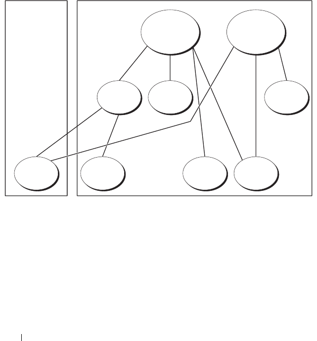
118 Using iDRAC6 With Microsoft Active Directory
Accumulating Privileges Using Extended Schema
The Extended Schema Authentication mechanism supports Privilege
Accumulation from different privilege objects associated with the same user
through different Association Objects. In other words, Extended Schema
Authentication accumulates privileges to allow the user the super set of all
assigned privileges corresponding to the different privilege objects associated
with the same user.
Figure 6-2 provides an example of accumulating privileges using Extended
Schema.
Figure 6-2. Privilege Accumulation for a User
The figure shows two Association Objects—A01 and A02. User1 is associated
to iDRAC2 through both association objects. Therefore, User1 has
accumulated privileges that are the result of combining the privileges set for
objects Priv1 and Priv2 on iDRAC2.
For example, Priv1 has these privileges: Login, Virtual Media, and Clear Logs
and Priv2 has these privileges: Login to iDRAC, Configure iDRAC, and Test
Alerts. As a result, User1 now has the privilege set: Login to iDRAC,
Virtual Media, Clear Logs, Configure iDRAC, and Test Alerts, which is the
combined privilege set of Priv1 and Priv2.
A01 A02
Group1 Priv1 Priv2
User1 User2 iDRAC1 iDRAC2
Domain 2Domain 1

Using iDRAC6 With Microsoft Active Directory 119
Extended Schema Authentication accumulates privileges to allow the user
the maximum set of privileges possible considering the assigned privileges of
the different privilege objects associated to the same user.
In this configuration, User1 has both Priv1 and Priv2 privileges on iDRAC2.
User1 has Priv1 privileges on iDRAC1 only. User2 has Priv1 privileges on both
iDRAC1 and iDRAC2. In addition, this figure shows that User1 can be in a
different domain and can be a member of a group.
Configuring Extended Schema Active Directory to Access iDRAC6
Before using Active Directory to access iDRAC6, configure the Active
Directory software and iDRAC6 by performing the following steps in order:
1
Extend the Active Directory schema (see "Extending the Active Directory
Schema").
2
Extend the Active Directory Users and Computers Snap-in (see "Installing
the Dell Extension to the Active Directory Users and Computers Snap-In").
3
Add iDRAC6 users and their privileges to Active Directory (see "Adding
iDRAC6 Users and Privileges to Active Directory").
4
Enable SSL on each of your domain controllers (see "Enabling SSL on a
Domain Controller").
5
Configure iDRAC6 Active Directory properties using either the iDRAC6
Web-based interface or the RACADM (see "Configuring Active Directory
With Extended Schema Using the iDRAC6 Web-Based Interface" or
"Configuring Active Directory With Extended Schema Using RACADM").
Extending your Active Directory schema adds a Dell organizational unit,
schema classes and attributes, and example privileges and association objects
to the Active Directory schema. Before you extend the schema, ensure that
you have Schema Admin privileges on the Schema Master Flexible Single
Master Operation (FSMO) Role Owner of the domain forest.
You can extend your schema using one of the following methods:
• Dell Schema Extender utility
• LDIF script file
If you use the LDIF script file, the Dell organizational unit will not be added
to the schema.

120 Using iDRAC6 With Microsoft Active Directory
The LDIF files and Dell Schema Extender are located on your Dell Systems
Management Tools and Documentation DVD in the following respective
directories:
•
DVD drive
:\SYSMGMT\ManagementStation\support\OMActiveDirectory_
Tools\Remote_Management_Advanced\LDIF_Files
•<
DVD drive
>:\SYSMGMT\ManagementStation\support\OMActiveDirecto
ry_Tools\Remote_Management_Advanced\Schema Extender
To use the LDIF files, see the instructions in the readme included in the
LDIF_Files directory. To use the Dell Schema Extender to extend the Active
Directory Schema, see "Using the Dell Schema Extender."
You can copy and run the Schema Extender or LDIF files from any location.
Using the Dell Schema Extender
CAUTION: The Dell Schema Extender uses the SchemaExtenderOem.ini file.
To ensure that the Dell Schema Extender utility functions properly, do not modify
the name of this file.
1
In the
Welcome
screen, click
Next.
2
Read and understand the warning and click
Next
.
3
Select
Use Current Log In Credentials
or enter a user name and password
with schema administrator rights.
4
Click
Next
to run the Dell Schema Extender.
5
Click
Finish
.
The schema is extended. To verify the schema extension, use the MMC
and the Active Directory Schema Snap-in to verify that the following exist:
• Classes (see Table 6-2 through Table 6-7)
• Attributes (Table 6-8)
See your Microsoft documentation for details about using the MMC and
the Active Directory Schema Snap-in.

Using iDRAC6 With Microsoft Active Directory 121
Table 6-2. Class Definitions for Classes Added to the Active Directory Schema
Class Name Assigned Object Identification Number (OID)
delliDRACDevice 1.2.840.113556.1.8000.1280.1.7.1.1
delliDRACAssociation 1.2.840.113556.1.8000.1280.1.7.1.2
dellRAC4Privileges 1.2.840.113556.1.8000.1280.1.1.1.3
dellPrivileges 1.2.840.113556.1.8000.1280.1.1.1.4
dellProduct 1.2.840.113556.1.8000.1280.1.1.1.5
Table 6-3. dellRacDevice Class
OID 1.2.840.113556.1.8000.1280.1.7.1.1
Description Represents the Dell iDRAC6 device. iDRAC6 must be
configured as delliDRACDevice in Active Directory.
This configuration enables iDRAC6 to send Lightweight
Directory Access Protocol (LDAP) queries to Active Directory.
Class Type Structural Class
SuperClasses dellProduct
Attributes dellSchemaVersion
dellRacType
Table 6-4. delliDRACAssociationObject Class
OID 1.2.840.113556.1.8000.1280.1.7.1.2
Description Represents the Dell Association Object. The Association Object
provides the connection between the users and the devices.
Class Type Structural Class
SuperClasses Group
Attributes dellProductMembers
dellPrivilegeMember

122 Using iDRAC6 With Microsoft Active Directory
Table 6-5. dellRAC4Privileges Class
OID 1.2.840.113556.1.8000.1280.1.1.1.3
Description Defines the privileges (Authorization Rights) for iDRAC6
Class Type Auxiliary Class
SuperClasses None
Attributes dellIsLoginUser
dellIsCardConfigAdmin
dellIsUserConfigAdmin
dellIsLogClearAdmin
dellIsServerResetUser
dellIsConsoleRedirectUser
dellIsVirtualMediaUser
dellIsTestAlertUser
dellIsDebugCommandAdmin
Table 6-6. dellPrivileges Class
OID 1.2.840.113556.1.8000.1280.1.1.1.4
Description Used as a container Class for the Dell Privileges (Authorization Rights).
Class Type Structural Class
SuperClasses User
Attributes dellRAC4Privileges
Table 6-7. dellProduct Class
OID 1.2.840.113556.1.8000.1280.1.1.1.5
Description The main class from which all Dell products are derived.
Class Type Structural Class
SuperClasses Computer
Attributes dellAssociationMembers

Using iDRAC6 With Microsoft Active Directory 123
Table 6-8. List of Attributes Added to the Active Directory Schema
Attribute Name/Description Assigned OID/Syntax Object Identifier Single
Valued
dellPrivilegeMember
List of dellPrivilege Objects that
belong to this Attribute.
1.2.840.113556.1.8000.1280.1.1.2.1
Distinguished Name (LDAPTYPE_DN
1.3.6.1.4.1.1466.115.121.1.12)
FALSE
dellProductMembers
List of dellRacDevice and
DelliDRACDevice Objects that
belong to this role. This attribute
is the forward link to the
dellAssociationMembers
backward link.
Link ID: 12070
1.2.840.113556.1.8000.1280.1.1.2.2
Distinguished Name (LDAPTYPE_DN
1.3.6.1.4.1.1466.115.121.1.12)
FALSE
dellIsLoginUser
TRUE if the user has Login rights
on the device.
1.2.840.113556.1.8000.1280.1.1.2.3
Boolean (LDAPTYPE_BOOLEAN
1.3.6.1.4.1.1466.115.121.1.7)
TRUE
dellIsCardConfigAdmin
TRUE if the user has Card
Configuration rights on
the device.
1.2.840.113556.1.8000.1280.1.1.2.4
Boolean (LDAPTYPE_BOOLEAN
1.3.6.1.4.1.1466.115.121.1.7)
TRUE
dellIsUserConfigAdmin
TRUE if the user has User
Configuration rights on the
device.
1.2.840.113556.1.8000.1280.1.1.2.5
Boolean (LDAPTYPE_BOOLEAN
1.3.6.1.4.1.1466.115.121.1.7)
TRUE
delIsLogClearAdmin
TRUE if the user has Log Clearing
rights on the device.
1.2.840.113556.1.8000.1280.1.1.2.6
Boolean (LDAPTYPE_BOOLEAN
1.3.6.1.4.1.1466.115.121.1.7)
TRUE
dellIsServerResetUser
TRUE if the user has Server Reset
rights on the device.
1.2.840.113556.1.8000.1280.1.1.2.7
Boolean (LDAPTYPE_BOOLEAN
1.3.6.1.4.1.1466.115.121.1.7)
TRUE
dellIsConsoleRedirectUser
TRUE if the user has Console
Redirection rights on the device.
1.2.840.113556.1.8000.1280.1.1.2.8
Boolean (LDAPTYPE_BOOLEAN
1.3.6.1.4.1.1466.115.121.1.7)
TRUE

124 Using iDRAC6 With Microsoft Active Directory
dellIsVirtualMediaUser
TRUE if the user has Virtual
Media rights on the device.
1.2.840.113556.1.8000.1280.1.1.2.9
Boolean (LDAPTYPE_BOOLEAN
1.3.6.1.4.1.1466.115.121.1.7)
TRUE
dellIsTestAlertUser
TRUE if the user has Test Alert
User rights on the device.
1.2.840.113556.1.8000.1280.1.1.2.10
Boolean (LDAPTYPE_BOOLEAN
1.3.6.1.4.1.1466.115.121.1.7)
TRUE
dellIsDebugCommandAdmin
TRUE if the user has Debug
Command Admin rights on
the vdevice.
1.2.840.113556.1.8000.1280.1.1.2.11
Boolean (LDAPTYPE_BOOLEAN
1.3.6.1.4.1.1466.115.121.1.7)
TRUE
dellSchemaVersion
The Current Schema Version is
used to update the schema.
1.2.840.113556.1.8000.1280.1.1.2.12
Case Ignore String
(LDAPTYPE_CASEIGNORESTRING
1.2.840.113556.1.4.905)
TRUE
dellRacType
This attribute is the Current RAC
Type for the delliDRACDevice
object and the backward link to
the dellAssociationObjectMembers
forward link.
1.2.840.113556.1.8000.1280.1.1.2.13
Case Ignore String
(LDAPTYPE_CASEIGNORESTRING
1.2.840.113556.1.4.905)
TRUE
dellAssociationMembers
List of
dellAssociationObjectMembers that
belong to this Product. This
attribute is the backward link to
the dellProductMembers linked
attribute.
Link ID: 12071
1.2.840.113556.1.8000.1280.1.1.2.14
Distinguished Name (LDAPTYPE_DN
1.3.6.1.4.1.1466.115.121.1.12)
FALSE
Table 6-8. List of Attributes Added to the Active Directory Schema (continued)
Attribute Name/Description Assigned OID/Syntax Object Identifier Single
Valued

Using iDRAC6 With Microsoft Active Directory 125
Installing the Dell Extension to the Active Directory Users and
Computers Snap-In
When you extend the schema in Active Directory, you must also extend the
Active Directory Users and Computers Snap-in so the administrator can
manage iDRAC6 devices, Users and User Groups, iDRAC6 Associations,
and iDRAC6 Privileges.
When you install your systems management software using the Dell Systems
Management Tools and Documentation DVD, you can extend the Snap-in by
selecting the Active Directory Users and Computers Snap-in option during
the installation procedure. See the Dell OpenManage Software Quick
Installation Guide for additional instructions about installing systems
management software. For 64-bit Windows Operating Systems, the Snap-in
installer is located under:
<DVD drive>:\SYSMGMT\ManagementStation\support\OMActiveDirect
ory_SnapIn64
For more information about the Active Directory Users and Computers
Snap-in, see your Microsoft documentation.
Installing the Administrator Pack
You must install the Administrator Pack on each system that is managing the
Active Directory iDRAC6 Objects. If you do not install the Administrator
Pack, you cannot view the Dell iDRAC6 Object in the container.
See "Opening the Active Directory Users and Computers Snap-In" for more
information.
Opening the Active Directory Users and Computers Snap-In
To open the Active Directory Users and Computers Snap-in:
1
If you are logged in to the domain controller, click
Start
Admin Tools
→
Active Directory Users and Computers
.
If you are not logged in to the domain controller, you must have the
appropriate Microsoft Administrator Pack installed on your local system. To
install this Administrator Pack, click
Start
→
Run
, enter
MMC
, and press
Enter
.
The MMC appears.
2
In the
Console 1
window, click
File
(or
Console
on systems running
Windows 2000).

126 Using iDRAC6 With Microsoft Active Directory
3
Click
Add/Remove Snap-in
.
4
Select the
Active Directory Users and Computers
Snap-in
and click
Add
.
5
Click
Close
and click
OK
.
Adding iDRAC6 Users and Privileges to Active Directory
Using the Dell-extended Active Directory Users and Computers Snap-in, you
can add iDRAC6 users and privileges by creating iDRAC6, Association, and
Privilege objects. To add each object type, perform the following procedures:
• Create an iDRAC6 device Object
• Create a Privilege Object
• Create an Association Object
• Add objects to an Association Object
Creating an iDRAC6 Device Object
1
In the MMC
Console Root
window, right-click a container.
2
Select
New
→
Dell Remote Management Object Advanced
.
The
New Object
window appears.
3
Enter a name for the new object. The name must be identical to the
iDRAC6 name that you will enter in Step A of "Configuring Active
Directory With Extended Schema Using the iDRAC6 Web-Based
Interface."
4
Select
iDRAC Device Object
.
5
Click
OK
.
Creating a Privilege Object
NOTE: A Privilege Object must be created in the same domain as the related
Association Object.
1
In the
Console Root
(MMC) window, right-click a container.
2
Select
New
→
Dell Remote Management Object Advanced
.
The
New Object
window appears.
3
Enter a name for the new object.
4
Select
Privilege Object
.

Using iDRAC6 With Microsoft Active Directory 127
5
Click
OK
.
6
Right-click the privilege object that you created, and select
Properties
.
7
Click the
Remote Management Privileges
tab and select the privileges
that you want the user or group to have (see Table 5-10).
Creating an Association Object
NOTE: The iDRAC6 Association Object is derived from Group and its scope is set to
Domain Local.
1
In the
Console Root
(MMC) window, right-click a container.
2
Select
New
→
Dell Remote Management Object Advanced
.
This opens the
New Object
window.
3
Enter a name for the new object.
4
Select
Association Object
.
5
Select the scope for the
Association Object
.
6
Click
OK
.
Adding Objects to an Association Object
Using the Association Object Properties window, you can associate users or
user groups, privilege objects, and iDRAC6 devices or iDRAC6 device groups.
You can add groups of Users and iDRAC6 devices. The procedure for creating
Dell-related groups and non-Dell-related groups is identical.
Adding Users or User Groups
1
Right-click the
Association Object
and select
Properties
.
2
Select the
Users
tab and click
Add
.
3
Enter the user or User Group name and click
OK
.
Adding Privileges
1
Select the
Privileges Object
tab and click
Add
.
2
Enter the Privilege Object name and click
OK
.
Click the Privilege Object tab to add the privilege object to the association that
defines the user’s or user group’s privileges when authenticating to an iDRAC6
device. Only one privilege object can be added to an Association Object.

128 Using iDRAC6 With Microsoft Active Directory
Adding iDRAC6 Devices or iDRAC6 Device Groups
To add iDRAC6 devices or iDRAC6 device groups:
1
Select the
Products
tab and click
Add
.
2
Enter iDRAC6 devices or iDRAC6 device group name and click
OK
.
3
In the
Properties
window, click
Apply
and click
OK
.
Click the Products tab to add one iDRAC6 device connected to the network
that is available for the defined users or user groups. You can add multiple
iDRAC6 devices to an Association Object.
Configuring Active Directory With Extended Schema Using the iDRAC6
Web-Based Interface
1
Open a supported Web browser window.
2
Log in to the iDRAC6 Web-based interface.
3
In the system tree, select
System
→
Remote Access
→
iDRAC
.
The
iDRAC Information
screen appears.
4
Click the
Network Security
tab, and then click
Active Directory
.
The
Active Directory Configuration and Management
screen appears.
5
Scroll to the bottom of the screen and click
Configure Active Directory
.
The
Step 1 of 4
Active Directory Configuration and Management
screen
appears.
6
To validate the SSL certificate of your Active Directory servers, select the
Enable Certificate Validation
check box under
Certificate Settings
.
If you don’t want to validate the SSL certificate of your Active Directory
servers, take no action, and skip to step 8.
7
Under
Upload Active Directory CA Certificate
, enter the file path of the
certificate or browse to find the certificate file, and then click
Upload
.
NOTE: You must enter the absolute file path, which includes the full path and
the complete file name and file extension.
The certificate information for the Active Directory CA certificate that you
uploaded appears in the
Current Active Directory CA Certificate
section.

Using iDRAC6 With Microsoft Active Directory 129
8
Click
Next
.
The
Step 2 of 4 Active Directory Configuration and Management
screen appears.
9
Select the
Enable Active Directory
check box.
10
Click
Add
to enter the user domain name, enter the user domain name in
the text field, and then click
OK
.
11
Type the user domain name in the prompt and click
OK
. Note that this
step is optional. If you configure a list of user domains, the list will be
available in the Web-based interface login screen. You can choose from
the list, and then you only need to enter the user name.
12
In the
Timeout
field, enter the number of seconds you want iDRAC6 to
wait for Active Directory responses. The default is 120 seconds.
13
Enter the
Domain Controller Server Address
. You can enter up to three
Active Directory servers for login processing, but you must configure at
least one server by entering the IP address or the fully qualified domain
name (FQDN). iDRAC6 attempts to connect to each configured server
until a connection is established.
NOTE: The FQDN or IP address that you specify in this field should match the
Subject or Subject Alternative Name field of your domain controller
certificate if you have certificate validation enabled.
14
Click
Next
.
The
Step 3 of 4 Active Directory Configuration and Management
screen appears.
15
Under
Schema Selection
, select the
Extended Schema
check box.
16
Click
Next
.
The
Step 4 of 4 Active Directory Configuration and Management
screen appears.
17
Under
Extended Schema Settings
, enter the iDRAC6 name and iDRAC6
domain name to configure the iDRAC6 device object and its location in
Active Directory.
18
Click
Finish
to save your changes, and then
Done
.
The main
Active Directory Configuration and Management
appears.
Next, you must test the Active Directory settings you just configured.

130 Using iDRAC6 With Microsoft Active Directory
19
Scroll to the bottom of the screen and click
Test Settings
.
The
Test Active Directory Settings
screen appears.
20
Enter your iDRAC6 user name and password, and then click
Start Test
.
Test results and the test log display. For additional information, see
"Testing Your Configurations."
NOTE: You must have a DNS server configured properly on iDRAC6 to support
Active Directory log in. Navigate to the Network Configuration screen (click
System
→
Remote Access
→
iDRAC
,
and then click the Network/Security tab) to
configure DNS server(s) manually or use DHCP to get DNS server(s).
You have completed the Active Directory configuration with Extended Schema.
Configuring Active Directory With Extended Schema Using RACADM
Use the following commands to configure the iDRAC6 Active Directory
feature with Extended Schema using the RACADM command line interface
(CLI) tool instead of the Web-based interface.
1
Open a command prompt and enter the following
RACADM
commands:
racadm config -g cfgActiveDirectory -o cfgADEnable 1
racadm config -g cfgActiveDirectory -o cfgADType 1
racadm config -g cfgActiveDirectory -o
cfgADRacName <RAC common name>
racadm config -g cfgActiveDirectory -o
cfgADRacDomain <
fully qualified rac domain name
>
racadm config -g cfgActiveDirectory -o
cfgDomainController1 <
fully qualified domain name
or IP Address of the domain controller
>
racadm config -g cfgActiveDirectory -o
cfgDomainController2 <
fully qualified domain name
or IP Address of the domain controller
>
racadm config -g cfgActiveDirectory -o
cfgDomainController3 <
fully qualified domain name
or IP Address of the domain controller
>

Using iDRAC6 With Microsoft Active Directory 131
NOTE: You must configure at least one of the three addresses. iDRAC6
attempts to connect to each of the configured addresses one-by-one until a
successful connection is made. With Extended Schema, these are the FQDN
or IP addresses of the domain controllers where this iDRAC6 device is
located. Global catalog servers are not used in extended schema mode at all.
If you want to disable the certificate validation during SSL handshake,
enter the following
RACADM
command:
racadm config -g cfgActiveDirectory -o
cfgADCertValidationEnable 0
In this case, you do not have to upload a CA certificate.
If you want to enforce the certificate validation during SSL handshake,
enter the following
RACADM
command:
racadm config -g cfgActiveDirectory -o
cfgADCertValidationEnable 1
In this case, you must upload a CA certificate using the following
RACADM
command:
racadm sslcertupload -t 0x2 -f <
ADS root CA
certificate
>
Using the following
RACADM
command may be optional. See "Importing
the iDRAC6 Firmware SSL Certificate" for additional information.
racadm sslcertdownload -t 0x1 -f <
RAC SSL
certificate
>
2
If DHCP is enabled on iDRAC6 and you want to use the DNS provided by
the DHCP server, enter the following
RACADM
command:
racadm config -g cfgLanNetworking -o
cfgDNSServersFromDHCP 1
3
If DHCP is disabled in iDRAC6 or you want to manually input your DNS
IP address, enter the following
RACADM
commands:
racadm config -g cfgLanNetworking -o
cfgDNSServersFromDHCP 0
racadm config -g cfgLanNetworking -o cfgDNSServer1
<primary DNS IP address>
racadm config -g cfgLanNetworking -o cfgDNSServer2
<secondary DNS IP address>
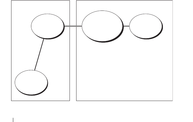
132 Using iDRAC6 With Microsoft Active Directory
4
If you want to configure a list of user domains so that you only need to
enter the user name during log in to the iDRAC6 Web-based interface,
enter the following command:
racadm config -g cfgUserDomain -o
cfgUserDomainName -i <index>
You can configure up to 40 user domains with index numbers between
1 and 40.
See "Using Active Directory to Log In to iDRAC6" for details about user
domains.
5
Press
Enter
to complete the Active Directory configuration with
Extended Schema.
Standard Schema Active Directory Overview
As shown in Figure 6-3, using standard schema for Active Directory
integration requires configuration on both Active Directory and iDRAC6.
Figure 6-3. Configuration of iDRAC6 with Microsoft Active Directory and
Standard Schema
Role
Group
Role
Group Name
and Domain
Name
Role
Definition
User
Configuration on Active
Directory Side
Configuration on
iDRAC Side

Using iDRAC6 With Microsoft Active Directory 133
On the Active Directory side, a standard group object is used as a role group.
A user who has iDRAC6 access will be a member of the role group. To give
this user access to a specific iDRAC6 card, the role group name and its
domain name need to be configured on the specific iDRAC6 card. Unlike the
extended schema solution, the role and the privilege level is defined on each
iDRAC6 card, not in the Active Directory. Up to five role groups can be
configured and defined in each iDRAC6. Table 6-9 shows the default role
group privileges.
NOTE: The Bit Mask values are used only when setting Standard Schema with
the RACADM.
Table 6-9. Default Role Group Privileges
Role
Groups
Default Privilege
Level
Permissions Granted Bit Mask
Role
Group 1
Administrator Login to iDRAC, Configure iDRAC,
Configure Users, Clear Logs,
Execute Server Control Commands,
Access Console Redirection,
Access Virtual Media, Test Alerts,
Execute Diagnostic Commands
0x000001ff
Role
Group 2
Operator Login to iDRAC, Configure iDRAC,
Execute Server Control Commands,
Access Console Redirection,
Access Virtual Media, Test Alerts,
Execute Diagnostic Commands
0x000000f9
Role
Group 3
Read Only Login to iDRAC 0x00000001
Role
Group 4
None No assigned permissions 0x00000000
Role
Group 5
None No assigned permissions 0x00000000

134 Using iDRAC6 With Microsoft Active Directory
Single Domain Versus Multiple Domain Scenarios
If all of the login users and role groups, as well as the nested groups, are in the
same domain, then only the domain controllers’ addresses must be configured
on iDRAC6. In this single domain scenario, any group type is supported.
If all of the login users and role groups, or any of the nested groups, are from
multiple domains, then Global Catalog server addresses are required to be
configured on iDRAC6. In this multiple domain scenario, all of the role
groups and nested groups, if any, must be Universal Group type.
Configuring Standard Schema Active Directory to Access iDRAC6
You must perform the following steps to configure Active Directory before an
Active Directory user can access iDRAC6:
1
On an Active Directory server (domain controller), open the
Active
Directory Users and Computers Snap-in.
2
Create a group or select an existing group. The name of the group and the
name of this domain must be configured on iDRAC6 by using either the
Web-based interface or RACADM (see "Configuring Active Directory
With Standard Schema Using the iDRAC6 Web-Based Interface" or
"Configuring Active Directory With Standard Schema Using RACADM").
3
Add the Active Directory user as a member of the Active Directory group
to access iDRAC6.
Configuring Active Directory With Standard Schema Using the iDRAC6
Web-Based Interface
1
Open a supported Web browser window.
2
Log in to the iDRAC6 Web interface.
3
In the system tree, select
System
→
Remote Access
→
iDRAC
.
4
Click the
Network Security
tab, and then click
Active Directory
.
The
Active Directory Configuration and Management
screen appears.
5
Scroll to the bottom of the screen and click
Configure Active Directory
.
The
Step 1 of 4 Active Directory Configuration and Management
screen appears.
6
Under
Certificate Settings
, select
Enable Active Directory
.

Using iDRAC6 With Microsoft Active Directory 135
7
Under
Upload Active Directory CA Certificate
, enter the file path of the
certificate or browse to find the certificate file, and then click
Upload
.
NOTE: You must enter the absolute file path, which includes the full path and
the complete file name and file extension.
The certificate information for the Active Directory CA certificate that you
uploaded appears in the
Current Active Directory CA Certificate
section.
8
Click Next.
The
Step 2 of 4 Active Directory Configuration and Management
screen appears.
9
Select the
Enable Active Directory
check box.
10
Click
Add
to enter the user domain name, enter the user domain name in
the text field, and then click
OK
.
11
In the
Timeout
field, enter the number of seconds you want iDRAC6 to
wait for Active Directory responses. The default is 120 seconds.
12
Enter the
Domain Controller Server Address
. You can enter up to three
Active Directory servers for login processing, but you must configure at
least one server by entering the IP address or the fully qualified domain
name (FQDN). iDRAC6 attempts to connect to each configured server
until a connection is established.
13
Click
Next
.
The
Step 3 of 4 Active Directory Configuration and Management
screen appears.
14
Under
Schema Selection
, select the
Standard Schema
check box.
15
Click
Next
.
The
Step 4a of 4 Active Directory Configuration and Management
screen appears.
16
Under
Standard Schema Settings
, enter the Global Catalog
Server Address(es).
NOTE: The Global Catalog server is only required for standard schema when
the user accounts and role groups are in different domains. And, in this
multiple domain case, only the Universal Group can be used.
17
Click a
Role Group
button to add a role group.
The
Step 4b of 4 Configure Role Group 1
screen appears.

136 Using iDRAC6 With Microsoft Active Directory
18
Enter the
Group Name
. The group name identifies the role group in the
Active Directory associated with iDRAC6.
19
Enter the
Group Domain
. The
Group Domain
is the fully qualified root
domain name for the forest.
20
In the
Role Group Privileges
section, set the group privileges. Refer to
Table 5-11 on page 93 for information on role group privileges.
NOTE: If you modify any of the permissions, the existing role group privilege
(Administrator, Power User, or Guest User) will change to either the Custom
Group or the appropriate role group privilege based on the permissions you
modified.
21
Click
OK
to save the role group settings.
An alert dialog appears, indicating that your settings are changed.
Click OK to return to the
Step 4a of 4 Active Directory Configuration
and Management
screen.
22
To add an additional role group, repeat step 17 through step 21.
23
Click
Finish
, and the click
Done
.
The main
Active Directory Configuration and Management
appears.
Next, you must test the Active Directory settings you just configured.
24
Scroll to the bottom of the screen and click
Test Settings
.
The
Test Active Directory Settings
screen appears.
25
Enter your iDRAC6 user name and password, and then click
Start Test
.
Test results and the test log display. For additional information,
see "Testing Your Configurations."
NOTE: You must have a DNS server configured properly on iDRAC6 to support
Active Directory login. Navigate to Remote Access→ Configuration→ Network
page to configure DNS server(s) manually or use DHCP to get DNS server(s).
You have completed the Active Directory configuration with Standard Schema.

Using iDRAC6 With Microsoft Active Directory 137
Configuring Active Directory With Standard Schema Using RACADM
Use the following commands to configure the iDRAC6 Active Directory
Feature with Standard Schema using the RACADM CLI instead of the
Web-based interface.
1
Open a command prompt and enter the following
RACADM
commands:
racadm config -g cfgActiveDirectory -o
cfgADEnable 1
racadm config -g cfgActiveDirectory -o cfgADType 2
racadm config -g cfgStandardSchema -i <index> -o
cfgSSADRoleGroupName <common name of the role
group>
racadm config -g cfgStandardSchema -i <index> -o
cfgSSADRoleGroupDomain <fully qualified domain
name>
racadm config -g cfgStandardSchema -i <index> -o
cfgSSADRoleGroupPrivilege <Bit Mask Number for
specific user permissions>
NOTE: For Bit Mask Number values, see Table B-1.
racadm config -g cfgActiveDirectory -o
cfgDomainController1 <fully qualified domain name
or IP address of the domain controller>
racadm config -g cfgActiveDirectory -o
cfgDomainController2 <fully qualified domain name
or IP address of the domain controller>
racadm config -g cfgActiveDirectory -o
cfgDomainController3 <fully qualified domain name
or IP address of the domain controller>
NOTE: Enter the FQDN of the domain controller, not the FQDN of the domain.
For example, enter servername.dell.com instead of dell.com.
NOTE: At least one of the 3 addresses is required to be configured. iDRAC6
attempts to connect to each of the configured addresses one-by-one until a
successful connection is made. With Standard Schema, these are the
addresses of the domain controllers where the user accounts and the role
groups are located.

138 Using iDRAC6 With Microsoft Active Directory
racadm config -g cfgActiveDirectory -o cfgGlobal
Catalog1 <fully qualified domain name or IP
address of the domain controller>
racadm config -g cfgActiveDirectory -o cfgGlobal
Catalog2 <fully qualified domain name or IP
address of the domain controller>
racadm config -g cfgActiveDirectory -o cfgGlobal
Catalog3 <fully qualified domain name or IP
address of the domain controller>
NOTE: The Global Catalog server is only required for standard schema when
the user accounts and role groups are in different domains. And, in this
multiple domain case, only the Universal Group can be used.
NOTE: The FQDN or IP address that you specify in this field should match the
Subject or Subject Alternative Name field of your domain controller certificate
if you have certificate validation enabled.
If you want to disable the certificate validation during SSL handshake,
enter the following
RACADM
command:
racadm config -g cfgActiveDirectory -o
cfgADCertValidationEnable 0
In this case, no Certificate Authority (CA) certificate needs to be uploaded.
If you want to enforce the certificate validation during SSL handshake,
enter the following
RACADM
command:
racadm config -g cfgActiveDirectory -o
cfgADCertValidationEnable 1
In this case, you must also upload the CA certificate using the following
RACADM
command:
racadm sslcertupload -t 0x2 -f <
ADS root CA
certificate
>
Using the following
RACADM
command may be optional. See "Importing
the iDRAC6 Firmware SSL Certificate" for additional information.
racadm sslcertdownload -t 0x1 -f <
RAC SSL
certificate
>

Using iDRAC6 With Microsoft Active Directory 139
2
If DHCP is enabled on iDRAC6 and you want to use the DNS provided by
the DHCP server, enter the following
RACADM
commands:
racadm config -g cfgLanNetworking -o
cfgDNSServersFromDHCP 1
3
If DHCP is disabled on iDRAC6 or you want manually to input your DNS
IP address, enter the following
RACADM
commands:
racadm config -g cfgLanNetworking -o
cfgDNSServersFromDHCP 0
racadm config -g cfgLanNetworking -o cfgDNSServer1
<
primary DNS IP address
>
racadm config -g cfgLanNetworking -o cfgDNSServer2
<
secondary DNS IP address>
4
If you want to configure a list of user domains so that you only need to
enter the user name when logging in to the Web-based interface, enter the
following command:
racadm config -g cfgUserDomain -o
cfgUserDomainName -i <index>
Up to 40 user domains can be configured with index numbers between
1 and 40.
See "Using Active Directory to Log In to iDRAC6" for details about
user domains.
Testing Your Configurations
If you want to verify whether your configuration works, or if you need to
diagnose the problem with your failed Active Directory log in, you can test
your settings from the iDRAC6 Web-based interface.
After you finish configuring settings in the iDRAC6 Web-based interface,
click Test Settings at the bottom of the screen. You will be required to enter a
test user's name (for example, username@domain.com) and password to run
the test. Depending on your configuration, it may take some time for all of
the test steps to complete and display the results of each step. A detailed test
log will display at the bottom of the results screen.

140 Using iDRAC6 With Microsoft Active Directory
If there is a failure in any step, examine the details in the test log to identify
the problem and a possible solution. For most common errors, see
"Frequently Asked Questions."
If you need to make changes to your settings, click the Active Directory tab
and change the configuration step-by-step.
Enabling SSL on a Domain Controller
When iDRAC6 authenticates users against an Active Directory domain
controller, it starts an SSL session with the domain controller. At this time,
the domain controller should publish a certificate signed by the Certificate
Authority (CA)—the root certificate of which is also uploaded into iDRAC6.
In other words, for iDRAC6 to authenticate to any domain controller—
whether it is the root or the child domain controller—that domain controller
should have an SSL-enabled certificate signed by the domain’s CA.
If you are using Microsoft Enterprise Root CA to automatically assign all your
domain controllers to an SSL certificate, perform the following steps to
enable SSL on each domain controller:
1
Enable SSL on each of your domain controllers by installing the SSL
certificate for each controller.
a
Click
Start
→
Administrative Tools
→
Domain Security Policy
.
b
Expand the
Public Key Policies
folder, right-click
Automatic
Certificate Request Settings
and click
Automatic Certificate Request
.
c
In the
Automatic Certificate Request Setup Wizard
, click
Next
and
select
Domain Controller
.
d
Click
Next
and click
Finish
.
Exporting the Domain Controller Root CA Certificate to iDRAC6
NOTE: If your system is running Windows 2000, the following steps may vary.
NOTE: If you are using a standalone CA, the following steps may vary.
1
Locate the domain controller that is running the Microsoft Enterprise
CA service.
2
Click
Start
→
Run
.
3
In the
Run
field, enter
mmc
and click
OK
.

Using iDRAC6 With Microsoft Active Directory 141
4
In the
Console 1
(MMC) window, click
File (
or
Console
on Windows 2000
systems
)
and select
Add/Remove Snap-in
.
5
In the
Add/Remove Snap-In
window, click
Add
.
6
In the
Standalone Snap-In
window, select
Certificates
and click
Add
.
7
Select
Computer
account and click
Next
.
8
Select
Local Computer
and click
Finish
.
9
Click
OK
.
10
In the
Console 1
window, expand the
Certificates
folder, expand the
Personal
folder, and click the
Certificates
folder.
11
Locate and right-click the root CA certificate, select
All Tasks
, and click
Export...
12
In the
Certificate Export Wizard
, click
Next
, and select
No do not export
the private key
.
13
Click
Next
and select
Base-64 encoded X.509 (.cer)
as the format.
14
Click
Next
and save the certificate to a directory on your system.
15
Upload the certificate you saved in step 14 to iDRAC6.
To upload the certificate using RACADM, see "Configuring Active
Directory With Standard Schema Using RACADM."
To upload the certificate using the Web-based interface, see "Configuring
Active Directory With Standard Schema Using the iDRAC6 Web-Based
Interface."
Importing the iDRAC6 Firmware SSL Certificate
NOTE: If the Active Directory Server is set to authenticate the client during an SSL
session initialization phase, you need to upload the iDRAC6 Server certificate to the
Active Directory Domain controller as well. This additional step is not required if the
Active Directory does not perform a client authentication during an SSL session’s
initialization phase.
Use the following procedure to import the iDRAC6 firmware SSL certificate
to all domain controller trusted certificate lists.
NOTE: If your system is running Windows 2000, the following steps may vary.
NOTE: If the iDRAC6 firmware SSL certificate is signed by a well-known CA and the
certificate of that CA is already in the domain controller's Trusted Root Certificate
Authority list, you are not required to perform the steps in this section.

142 Using iDRAC6 With Microsoft Active Directory
The iDRAC6 SSL certificate is the identical certificate used for the iDRAC6
Web server. All iDRAC6 controllers are shipped with a default self-signed
certificate.
To download the iDRAC6 SSL certificate, run the following RACADM
command:
racadm sslcertdownload -t 0x1 -f <RAC SSL certificate>
1
On the domain controller, open an
MMC Console
window and select
Certificates
→
Trusted Root Certification Authorities
.
2
Right-click
Certificates
, select
All Tasks
and click
Import
.
3
Click
Next
and browse to the SSL certificate file.
4
Install the iDRAC6 SSL Certificate in each domain controller’s
Trusted
Root Certification Authority
.
If you have installed your own certificate, ensure that the CA signing your
certificate is in the
Trusted Root Certification Authority
list. If the
Authority is not in the list, you must install it on all your Domain Controllers.
5
Click
Next
and select whether you would like Windows to automatically
select the certificate store based on the type of certificate, or browse to a
store of your choice.
6
Click
Finish
and click
OK
.
Using Active Directory to Log In to iDRAC6
You can use Active Directory to log in to iDRAC6 using one of the following
methods:
• Web-based interface
• Local RACADM
• SSH or telnet console for SM-CLP CLI
The login syntax is the same for all three methods:
<
username@domain
>
or
<
domain>\<username
> or <
domain>/<username
>
where
username
is an ASCII string of 1–256 bytes.

Using iDRAC6 With Microsoft Active Directory 143
White space and special characters (such as \, /, or @) cannot be used in the
user name or the domain name.
NOTE: You cannot specify NetBIOS domain names, such as Americas, because
these names cannot be resolved.
If you log in from the Web-based interface and you have configured user
domains, the Web-based interface log in screen will list all the user domains in
the pull-down menu for your to choose. If you select a user domain from the
pull-down menu, you should only enter the user name. If you select
This iDRAC, you can still log in as an Active Directory user if you use the login
syntax described above in "Using Active Directory to Log In to iDRAC6."
Frequently Asked Questions
Active Directory Log In Issues
My Active Directory log in failed. What do I do?
iDRAC6 provides a diagnostic tool in the Web-based interface.
1
Log in as a local user with administrator privilege from the Web-based
interface.
2
In the system tree, select
System
→
Remote Access
→
iDRAC
.
3
Click the
Network/Security
tab, and then click the
Active Directory
sub-tab
.
The
Active Directory Configuration and Management
screen appears.
4
Scroll to the bottom of the screen and click
Test Settings
.
The
Test Active Directory Settings
screen appears.
5
Enter a test user name and password, and then click
Start Test
.
iDRAC6 runs the tests step-by-step and displays the result for each step.
iDRAC6 also logs a detailed test result to help you resolve any problems.
If problems persist:
a
On the
Test Settings
screen, click the
Active Directory
sub-tab to return
to the
Active Directory Configuration and Management
screen.
b
Scroll to the bottom of the screen and click
Configure Active Directory
.
c
Change your user configuration, and run the test again until the test
user passes the authorization step.

144 Using iDRAC6 With Microsoft Active Directory
I enabled certificate validation but I failed my Active Directory log in. I ran the
diagnostics from the GUI and the test result shows the following error message:
ERROR: Can't contact LDAP server,
error:14090086:SSL
routines:SSL3_GET_SERVER_CERTIFICATE:certificate
verify failed: Please check the correct
Certificate Authority (CA) certificate has been
uploaded to iDRAC. Please also check if the iDRAC
date is within the valid period of the
certificates and if the Domain Controller Address
configured in iDRAC matches the subject of the
Directory Server Certificate.
What could the problem be and how do I fix it?
If certificate validation is enabled, iDRAC6 uses the uploaded CA certificate
to verify the directory server certificate when iDRAC6 establishes the SSL
connection with the directory server. The most common reasons for failing
certification validation are:
• The iDRAC6 date is not within the valid period of the server certificate or
CA certificate. Check the iDRAC6 time and the valid period of
your certificate.
• The Domain Controller Addresses configured in iDRAC6 do not match
the Subject or Subject Alternative Name of the directory server certificate.
– If you are using an IP address, see "I'm using an IP address for a
Domain Controller Address, and I failed certificate validation. What's
the problem?".
– If you are using FQDN, ensure you are using the FQDN of the domain
controller, and not the domain itself. For example, use
servername.example.com
and
not
example.com.

Using iDRAC6 With Microsoft Active Directory 145
What should I check if I cannot log in to iDRAC6 using Active Directory?
First, diagnose the problem using the Test Settings feature. For directions,
see "My Active Directory log in failed. What do I do?"
Then, fix the specific problem indicated by the test results.
For additional
information, see "Testing Your Configurations."
Most common issues are explained in this section. However, in general,
you should check the following:
1
Ensure that you use the correct user domain name during a log in and not
the NetBIOS name.
2
If you have a local iDRAC6 user account, log in to iDRAC6 using your
local credentials.
3
Check the following settings:
a
Navigate to the
Active Directory Configuration and Management
screen. Select
System
→
Remote Access
→
iDRAC
, click the
Network/
Security
tab, and then click the
Active Directory
subtab.
b
Ensure that the
Active Directory Enabled
check box is checked.
c
If you enabled certificate validation, ensure that you have uploaded
the correct Active Directory root CA certificate to iDRAC6. The
certificate appears in the
Active Directory CA Certificate
area.
Ensure that the iDRAC6 time is within the valid period of the CA
certificate.
d
If you are using the Extended Schema, ensure that the
iDRAC Name
and
iDRAC Domain Name
match your Active Directory environment
configuration.
If you are using the Standard Schema, ensure that the
Group Name
and
Group Domain Name
match your Active Directory configuration.
e
Navigate to the Network Configuration screen. Select
System
→
Remote Access
→
iDRAC
, and then click
Network/Security
.
Ensure that the DNS settings are correct.
f
Check the Domain Controller SSL certificates to ensure that the
iDRAC6 time is within the valid period of the certificate.

146 Using iDRAC6 With Microsoft Active Directory
Active Directory Certificate Validation
I'm using an IP address for a Domain Controller Address, and I failed certificate
validation. What's the problem?
Check the
Subject or Subject Alternative Name
field of your domain controller
certificate. Usually Active Directory uses the hostname, not the IP address,
of the domain controller in the
Subject or Subject Alternative Name
field of
the domain controller certificate. You can fix the problem by taking any of
the following actions:
• Configure the hostname (FQDN) of the domain controller as the
domain
controller address(es)
on iDRAC6 to match the Subject or Subject
Alternative Name of the server certificate.
• Re-issue the server certificate to use an IP address in the Subject or
Subject Alternative Name field so it matches the IP address configured
in iDRAC6.
• Disable certificate validation if you choose to trust this domain controller
without certificate validation during the SSL handshake.
Why does iDRAC6 enable certificate validation by default?
iDRAC6 enforces strong security to ensure the identity of the domain
controller that iDRAC6 connects to. Without certificate validation, a hacker
could spoof a domain controller and hijack the SSL connection. If you choose
to trust all the domain controllers in your security boundary without
certificate validation, you can disable it through the GUI or the CLI.
Extended and Standard Schema
I'm using extended schema in a multiple domain environment. How do I configure
the domain controller address(es)?
Use the host name (FQDN) or the IP address of the domain controller(s) that
serves the domain in which the iDRAC6 object resides.
Do I need to configure Global Catalog Address(es)?
If you are using extended schema, you cannot configure global catalog
addresses, because they are not used with extended schema.

Using iDRAC6 With Microsoft Active Directory 147
If you are using standard schema, and users and role groups are from different
domains, you must configure global catalog address(es). In this case, you can
use only Universal Group.
If you are using standard schema, and all the users and all the role groups are
in the same domain, you are not required to configure global catalog
address(es).
How does standard schema query work?
iDRAC6 connects to the configured domain controller address(es) first. If the
user and role groups reside in that domain, the privileges are saved.
If global controller address(es) is configured, iDRAC6 continues to query the
Global Catalog. If additional privileges are retrieved from the Global Catalog,
these privileges are accumulated.
Miscellaneous
Does iDRAC6 always use LDAP over SSL?
Yes. All the transportation is over secure port 636 and/or 3269.
During test setting, iDRAC6 does a LDAP CONNECT only to help isolate
the problem, but it does not do an LDAP BIND on an insecure connection.
Does iDRAC6 support the NetBIOS name?
Not in this release.

148 Using iDRAC6 With Microsoft Active Directory

Viewing the Configuration and Health of the Managed Server 149
Viewing the Configuration and
Health of the Managed Server
System Summary
Click System→ Properties→ Summary to obtain information about the
Main System Enclosure and the Integrated Dell Remote Access Controller.
Main System Enclosure
System Information
This section of the iDRAC6 Web interface provides the following basic
information about the managed server:
• Description — The model number or name of the managed server
• BIOS Version — The version number of the managed server's BIOS
• Service Tag — The Service Tag number of the managed server
• Host Name — The DNS hostname associated with the managed server
• OS Name — The name of the operating system installed on the
managed server
I/O Mezzanine Card
This section of the iDRAC6 Web interface provides the following
information about the I/O Mezzanine cards installed on the managed server:
• Connection — Lists the I/O Mezzanine card(s) installed on the
managed server
• Card Type — The physical type of the installed Mezzanine card/connection
• Model Name — The model number, type, or description of the installed
Mezzanine card(s)

150 Viewing the Configuration and Health of the Managed Server
Integrated Storage Card
This section of the iDRAC6 Web interface provides information about the
integrated Storage Controller Card installed on the Managed Server:
• Card Type — shows the model name of the installed storage card
Auto Recovery
This section of the iDRAC6 Web interface details the current mode of
operation of the Auto Recovery feature of the managed server as set by
Open Manage Server Administrator:
• Recovery Action — Action to be performed when a system fault or
hang
is
detected. Available actions are
No Action
,
Hard Reset
,
Power Down
,
or
Power Cycle
.
• Initial Countdown — The amount of time (in seconds) after a system
hang is detected at which time iDRAC6 performs a recovery action.
• Present Countdown — The current value (in seconds) of the
countdown timer.
Integrated Dell Remote Access Controller 6 - Enterprise
iDRAC6 Information
This section of the iDRAC6 Web interface provides the following
information about iDRAC6 itself:
• Date/Time — The current date and time (as of last page refresh) of iDRAC6
• Firmware Version — The current version of iDRAC6 firmware installed on
the managed server
• Firmware Updated — The date and time of the last successful iDRAC6
firmware update
• Hardware Version — The version number of the primary planar
(circuit board) of the managed server
• IP Address — The IP address associated with iDRAC6 (not the
managed server)
• Gateway — The IP address of the network gateway configured for iDRAC6
• Subnet Mask — The TCP/IP Subnet Mask configured for iDRAC6
• MAC Address — The MAC address associated with the LOM (LAN on
Motherboard) Network Interface Controller of iDRAC6

Viewing the Configuration and Health of the Managed Server 151
• DHCP Enabled — Enabled if iDRAC6 is set to fetch its IP address and
associated info from a DHCP server
• Preferred DNS Address 1 — Set to the currently active primary DNS server
• Alternate DNS Address 2 — Set to the alternate DNS server address
NOTE: This information is also available at iDRAC→ Properties→ iDRAC Information.
WWN/MAC Summary
Click System→ Properties→ WWN/MAC to view the current configuration
of installed I/O Mezzanine cards and their associated network fabrics. If the
FlexAddress feature is enabled, the globally assigned (Chassis-Assigned)
persistent MAC addresses supersede the hardwired values of each LOM.
System Health
Click System→ Properties→ Health to view important information about
the health of iDRAC6 and components monitored by iDRAC6. The Severity
column shows the status for each component. For a list of status icons and
their meaning, see Table 17-3. Click the component name in the Component
column for more detailed information about the component.
NOTE: Component information can also be obtained by clicking the component
name in the left pane of the window. Components remain visible in the left pane
independent of the tab/screen that is selected.
iDRAC6
The iDRAC6 Information screen lists a number of important details about
iDRAC6, such as health status, name, firmware revision, and network
parameters. Additional details are available by clicking the appropriate tab at
the top of the screen.
CMC
The CMC screen displays the health status, firmware revision, and IP address
of the Chassis Management Controller. You can also launch the CMC Web
interface by clicking the Launch the CMC Web Interface button. See the
Chassis Management Controller Firmware User Guide.

152 Viewing the Configuration and Health of the Managed Server
Batteries
The Batteries screen displays the status and values of the system board
coin-cell battery that maintains the Real-Time Clock (RTC) and CMOS
configuration data storage of the managed system.
Temperatures
The Temperature Probes Information screen displays the status and readings
of the on-board ambient temperature probe. Minimum and maximum
temperature thresholds for warning or failure states are shown, along with the
current health status of the probe.
Voltages
The Voltage Probes Information screen displays the status and reading of the
Voltage probes, providing such information as the status of the on-board
voltage rail and CPU core sensors.
NOTE: Depending on the model of your server, temperature thresholds for warning
or failure states and/or the health status of the probe may not be displayed.
Power Monitoring
The Power Monitoring screen enables you to view the following monitoring
and power statistics information:
• Power Monitoring — Displays the amount of power being used (in watts)
by the server as reported by the System Board Current Monitor.
• Power Tracking Statistics — Displays information about the amount of
power used by the system since the
Measurement Start Time
was last
reset.
• Peak Statistics — Displays information about the peak amount of power
used by the system since the
Measurement Start Time
was last reset.
CPU
The CPU Information screen reports the health of each CPU on the
managed server. This health status is a roll-up of a number of individual
thermal, power, and functional tests.

Viewing the Configuration and Health of the Managed Server 153
POST
The Post Code screen displays the last system post code (in hexadecimal)
prior to booting the operating system of the managed server.
Misc Health
The Misc Health screen provides access to the following system logs:
• System Event Log — Displays system-critical events that occur on the
managed system.
• Post Code — Displays the last system post code (in hexadecimal) prior to
booting the operating system of the managed server.
• Last Crash — Displays the most recent crash screen and time.
• Boot Capture — Provides playback of the last three boot screens.
NOTE: This information is also available at System→ Properties→ Logs.

154 Viewing the Configuration and Health of the Managed Server

Power Monitoring and Power Management 155
Power Monitoring and Power
Management
Dell™ PowerEdge™ systems incorporate many new and enhanced power
management features. The entire platform, from hardware to firmware to
systems management software, has been designed with a focus on power
efficiency, power monitoring, and power management.
PowerEdge systems provide many features for monitoring and managing power:
•
Power Monitoring:
iDRAC6 collects a history of power measurements
and calculates running averages, peaks, and so on. Using the iDRAC6
Web-based interface, you can view the information on the
Power
Monitoring
screen. You can also view the information in graph form by
clicking
Show Graph
at the bottom of the
Power Monitoring
screen.
See "Power Control" for more information.
•
Power Budgeting:
At boot, a system inventory enables a system power
budget of the current configuration to be calculated. See "Power
Monitoring" for more information.
•
Power Control:
iDRAC6 enables you to remotely perform
several
power management actions on the managed system
. See "Power Control"
for more information.
Configuring and Managing Power
You can use the iDRAC6 Web-based interface and RACADM command line
interface (CLI) to manage and configure power controls on the PowerEdge
system. Specifically, you can:
• View the power status of the server. See "Viewing Power Monitoring."
• View power budget information for the server, including the minimum and
maximum potential power consumption. See "Viewing Power Budget."

156 Power Monitoring and Power Management
• View power budget threshold for the server. See "Viewing Power Budget
Threshold."
• Execute power control operations on the server (for example, power on,
power off, system reset, power cycle). See "Executing Power Control
Operations on the Server."
Power Monitoring
iDRAC6 monitors the power consumption in PowerEdge servers continuously.
iDRAC6 calculates the following power values and provides the information
through its Web-based interface or RACADM CLI
:
• Cumulative power
• Average, minimum, and maximum power
• Power consumption (also shown in graphs in the Web-based interface)
• Power budget thresholds
Viewing Power Monitoring
Using the Web Interface
To view the power monitoring data:
1
Log in to the iDRAC6 Web interface.
2
In the system tree, select
Power Monitoring
.
The
Power Monitoring
screen appears, displaying the following information:
Power Monitoring
•
Status
: A
green check
indicates that the power status is normal,
Warning
indicates that a warning alert was issued, and
Severe
indicates a failure
alert was issued.
•
Probe Name
: System Board System Level. This description indicates the
probe is being monitored by its location in the system.
•
Reading
: The current power consumption in Watts.
Amperage
•
Location
: System Board Current Monitor Current
•
Reading
: The current power consumption in Amps

Power Monitoring and Power Management 157
Power Tracking Statistics
• Statistic:
–
Cumulative System Power
displays the current cumulative energy
consumption (in KWh) for the server. The value represents the total
energy used by the system. You can reset this value to 0 by clicking
Reset
at the end of the table row.
–
System Peak Power
specifies the system peak value in Watts within
the interval specified by the
Measurement Start Time
and
Measure
Current Time
. You can reset this value to 0 by clicking
Reset
at the
end of the table row.
–
System Peak Amperage
specifies the system peak amperage within the
interval specified by the
Measurement Start Time
and
Measure
Current Time
. You can reset this value to 0 by clicking
Reset
at the
end of the table row.
•
Measurement Start Time
displays the date and time recorded when the
system energy consumption value was last cleared and the new
measurement cycle began. For
Cumulative System Power
,
System Peak
Amperage
, and
System Peak Power
statistics, you can reset each value to 0
by clicking
Reset
at the end of the table row; however, it will persist
through a system reset or CMC failover operation.
•
Measurement Current Time
for
Cumulative System Power
displays the
current date and time when the system energy consumption was
calculated for display. For
System Peak Amperage
and
System Peak Power
,
the
Peak Time
fields display the time when these peaks occurred.
•
Reading
: The amount of power (in KWh) used since the counter was started.
NOTE: Power Tracking Statistics are maintained across system resets and so reflect
all activity in the interval between the stated Start and Finish Times.The Reset Max
Peaks button will reset to peak statistics value. In the next table, Power Consumption
data is not maintained across system resets and so will reset back to peak statistics
value. The power values displayed are cumulative averages over the respective time
interval (previous minute, hour, day and week). Since the Start to Finish time intervals
here may differ from those of the Power Tracking Statistics ones, peak power values
(Max Peak Watts versus Max Power Consumption) may differ.

158 Power Monitoring and Power Management
Power Consumption
•
Average Power Consumption
: Average over previous minute, previous
hour, previous day and previous week.
•
Max Power Consumption
and
Min Power Consumption
: The maximum
and minimum power consumptions observed within the given time interval.
•
Max Power Time
and
Min Power Time
: The times (by minute, hour, day,
and week) when the maximum and minimum power consumptions occurred.
Show Graph
Click Show Graph to display graphs illustrating iDRAC6 power consumption
in Watts over the last hour, 24 hours, three days, and one week. Use the
drop-down menu provided above the graph to select the time period.
NOTE: Each data point plotted on the graphs represents the average of readings
over a 5 minute period. As a result, the graphs may not reflect brief fluctuations in
power or current consumption.
Power Budgeting
iDRAC6 can be configured to enforce the minimum and maximum power
threshold limits, as set by the CMC, for the current system configuration.
The Power Budget screen displays these power threshold limits, which cover the
range of AC power consumptions a thresholded system under heavy workload will
present to the datacenter. These limits are not configurable.
Viewing Power Budget
The server provides power budget status overviews of the power subsystem on the
Power Budget Information screen.
Using the Web Interface
NOTE: To perform power management actions, you must have Administrative
privilege.
1
Log in to the iDRAC6 Web-based interface.
2
In the system tree, select
System
.
3
Click the
Power Management
tab, and then click
Power Budget
.
The
Power Budget Information
screen appears.

Power Monitoring and Power Management 159
The Power Budget Information table displays the minimum and maximum
limits of power thresholds for the current system configuration. These cover
the range of AC power consumptions a thresholded system under heavy
workload will present to the datacenter.
•
Minimum Potential Power Consumption
represents the lowest Power
Budget Threshold value.
•
Maximum Potential Power Consumption
represents the highest Power
Budget Threshold value. This value is also the current system
configuration's absolute maximum power consumption.
Using RACADM
On a Managed Node, open a command line interface and enter:
racadm getconfig -g cfgServerPower
NOTE: For more information about cfgServerPower, including output details,
see "cfgServerPower."
Viewing Power Budget Threshold
Power Budget Threshold, if enabled, enforces power limits for the system.
System performance is dynamically adjusted to maintain power consumption
near the specified threshold.
NOTE: Power budget threshold is read-only and cannot be enabled or configured
in iDRAC6.
Actual power consumption may be less for light workloads and momentarily
exceed the threshold until performance adjustments have completed.
Using the Web-Based Interface
1
Log in to the iDRAC6 Web-based interface.
2
In the system tree, select
System
.
3
Click the
Power Management
tab, and then click
Power Budget
.
The
Power Budget Information
screen appears.
4
Click
Power Budget Threshold
.

160 Power Monitoring and Power Management
The Power Budget Threshold table displays the power limit information for
the system:
•
Enabled
indicates whether the system enforces the power budget threshold.
•
Threshold in Watts
and
Threshold in BTU/hr
display the limit in Watts
and BTU/hr, respectively.
•
Threshold Percentage
displays the percentage of power range.
Using RACADM
On a Managed Node, open a command line interface and enter:
racadm getconfig -g cfgServerPower -o
cfgServerPowerCapWatts <
power cap value in Watts
>
racadm getconfig -g cfgServerPower -o
cfgServerPowerCapBTUhr <
power cap value in BTU/hr
>
racadm getconfig -g cfgServerPower -o
cfgServerPowerCapPercent <
power cap value in %
>
NOTE: For more information about cfgServerPower, including output details,
see "cfgServerPower."
Power Control
iDRAC6 enables you to remotely perform
a power-on, reset, graceful shutdown,
non-masking interruption (NMI), or power cycle
. Use the Power Control screen
to perform an orderly shutdown through the operating system when rebooting and
powering on or off.
Executing Power Control Operations on the Server
NOTE: To perform power management actions, you must have Chassis Control
Administrator privilege.
iDRAC6 enables you to remotely perform a power-on, reset, graceful shutdown,
NMI, or power cycle.
Using the Web Interface
1
Log in to the iDRAC6 Web interface.
2
In the system tree, select
System
.

Power Monitoring and Power Management 161
3
Click the
Power Management
tab.
The
Power Control
screen displays.
4
Select one of the following
Power Control Operations
by clicking its
radio button:
–
Power On System
turns on the server (the equivalent of pressing the
power button when the server power is off). This option is disabled if
the system is already powered on.
–
Power Off System
turns off the server. This option is disabled if the
system is already powered off.
–
NMI (Non-Masking Interrupt)
generates an NMI to halt system
operation. An NMI sends a high-level interrupt to the operating
system, which causes the system to halt operation to allow for critical
diagnostic or troubleshooting activities.
–
Graceful Shutdown
attempts to cleanly shutdown the operating
system, then powers off the system. Graceful shutdown requires an
ACPI (Advanced Configuration and Power Interface)-aware operating
system, which allows for system directed power management.
–
Reset System (warm boot)
reboots the system without powering off.
This option is disabled if the system is already powered off.
–
Power Cycle System
(cold boot)
powers off and then reboots the system.
This option is disabled if the system is already powered off.
5
Click
Apply
.
A dialog box appears requesting confirmation.
6
Click
OK
to execute the power management action you selected.
Using RACADM
Open a Managed Node open command line interface text console to the server,
log in, and enter:
racadm serveraction <action>
where <action> is powerup, powerdown, powercycle, hardreset,
or powerstatus.
NOTE: For more information about serveraction, including output details,
see "serveraction."

162 Power Monitoring and Power Management

Configuring and Using Serial Over LAN 163
Configuring and Using Serial
Over LAN
Serial Over LAN (SOL) is an IPMI feature that allows a managed server’s text
based console data that would traditionally be sent to the serial I/O port to be
redirected over the iDRAC’s dedicated Out of Band Ethernet management
network. The SOL out-of-band console enables system administrators to
remotely manage the blade server’s text-based console from any location with
network access. Benefits of SOL are as follows:
• Remotely access operating systems with no timeout.
• Diagnose host systems on Emergency Management Services (EMS) or
Special Administrator Console (SAC) for Windows or in a Linux shell.
• View the progress of a blade server during POST and reconfigure the BIOS
setup program (while redirected to a serial port).
Enabling Serial Over LAN in the BIOS
To configure the server for Serial Over LAN, the following configuration steps
are required and will be explained in detail.
1
Configure Serial Over LAN in BIOS (disabled by default)
2
Configure iDRAC6 for Serial over LAN
3
Select a method to initialize Serial Over LAN (SSH, telnet, SOL Proxy, or
IPMI Tool)
4
Configure the OS for SOL

164 Configuring and Using Serial Over LAN
Serial communication is off by default in BIOS. In order to redirect the host
text console data to Serial over LAN, you must enable console redirection via
COM1. To change the BIOS setting, perform the following steps:
1
Boot the managed server.
2
Press <F2> to enter the BIOS setup utility during POST.
3
Scroll down to Serial Communication and press <Enter>.
In the pop-up window, the serial communication list is presented with the
following options:
•Off
• On without console redirection
• On with console redirection via COM1
Use the arrow keys to navigate between options.
4
Ensure that
On with console redirection via COM1
is enabled.
5
Ensure that the
Failsafe Baud Rate
is identical to SOL baud rate that is
configured on iDRAC. The default value for both the failsafe baud rate
and the iDRAC’s SOL baud rate setting is 115.2 kbps.
6
Enable the
Redirection After Boot
(the default value is DISABLED).
This option enables BIOS SOL redirection across subsequent reboots.
7
Save the changes and exit.
The managed server reboots.
Configuring Serial Over LAN in the iDRAC6
Web GUI
1
Open the
Serial Over LAN Configuration
screen by selecting
System
→
Remote Access
→
iDRAC
→
Network/Security
→
Serial Over LAN
.
2
Ensure the
Enable Serial Over LAN
option is selected (enabled). By
default it is enabled.
3
Update the IPMI SOL baud rate by selecting a data speed from the
Baud
Rate
drop-down menu. The options are 19.2 kbps, 57.6 kbps, and 115.2
kbps. The default value is 115.2 kbps.
NOTE: Ensure that the SOL baud rate is identical to the Failsafe Baud Rate
that was set in BIOS.

Configuring and Using Serial Over LAN 165
4
Click
Apply
if you have made any changes.
5
Change the configuration on the
Advanced Settings
screen, if necessary.
Dell recommends using the default values.
Advanced Settings
allows you
to adjust SOL performance by changing the
Character Accumulate
Interval
and
Character Send Threshold
values. For optimal performance,
use the default settings of 10 milliseconds and 250 characters, respectively.
Table 9-1. Serial Over LAN Configuration Settings
Setting Description
Enable Serial
Over LAN
When selected, the checkbox indicates that Serial Over LAN is
enabled.
Baud Rate Indicates the data speed. Select a data speed of 19.2 kbps, 57.6
kbps, or 115.2 kbps.
Table 9-2. Serial Over LAN Configuration Buttons
Button Description
Print Prints the Serial Over LAN Configuration values that appear on
the screen.
Refresh Reloads the Serial Over LAN Configuration screen.
Advanced
Settings
Opens the Serial Over LAN Configuration Advanced Settings
screen.
Apply Supplies any new settings that you make while viewing the Serial
Over LAN Configuration screen.
166 Configuring and Using Serial Over LAN
NOTE: If you change these values to lower values, the console redirection
feature of SOL may experience a reduction in performance. Furthermore,
the SOL session must wait to receive an acknowledgement for each packet
before sending the next packet. As a result, the performance is
significantly reduced.
6
Configure SSH/Telnet for SOL at
System
→
Remote Access
→
iDRAC
→
Network/Security
→
Services
.
NOTE: Each blade server only supports one active SOL session through
SSH or Telnet protocol.
Table 9-3. Serial Over LAN Configuration Advanced Settings
Setting Description
Character
Accumulate
Interval
The typical amount of time iDRAC6 waits before sending a partial
SOL data packet. This parameter is specified in milliseconds and
increments by 10 milliseconds.
Character Send
Threshold
Specifies the number of characters per SOL data packet. As soon
as the number of characters accepted by iDRAC6 is equal to or
greater than the Character Send Threshold value, iDRAC6 starts
transmitting SOL data packets that contain numbers of characters
equal to or less than the Character Send Threshold value. If a
packet contains fewer characters than this value, it is defined to be
a partial SOL data packet.
Table 9-4. Serial Over LAN Configuration Advanced Settings Buttons
Button Description
Print Prints the Serial Over LAN Configuration Advanced
Settings values that appear on the screen.
Refresh Reloads the Serial Over LAN Configuration Advanced
Settings screen.
Apply Saves any new settings that you make while viewing the
Serial Over LAN Configuration Advanced Settings screen.
Go Back To Serial Over
LAN Configuration
Page
Returns the user to the Serial Over LAN Configuration
screen.

Configuring and Using Serial Over LAN 167
NOTE: SSH protocol is enable by default. Telnet protocol is disabled
by default.
7
Click
Services
to open the
SSH and Telnet Configuration
screen.
NOTE: SSH and Telnet programs both provide access on a remote machine.
8
Click
Enable
on either
SSH
or
Telnet
as required.
9
Click
Apply
.
NOTE: SSH is a recommended method due to better security and
encryption mechanisms.
NOTE: SSH/Telnet session duration can be infinite as long as the timeout
value is set to 0. The default timeout value is 1800 seconds.
10
Enable iDRAC6 Out-of-Band interface (IPMI over LAN) by selecting
System
→
Remote Access
→
iDRAC
→
Network/Security
→
Network
.
11
Enable the
IPMI Over LAN
option under
IPMI LAN Settings
.
IPMI Over LAN
functionality is disabled by default.
12
Click
Apply
.
Using Serial Over LAN (SOL)
This section provides several methods to initialize a Serial-Over-LAN session
including a Telnet program, an SSH client, IPMItool, and SOL Proxy.
The purpose of Serial Over LAN feature is to redirect the serial port of the
managed server through iDRAC6 into the console of your management station.
Model for Redirecting SOL Over Telnet or SSH
Telnet (port 23)/ SSH (port 22) client
←→
WAN connection
←→
iDRAC6 server
The IPMI-based SOL over SSH/Telnet implementation eliminates the need for
an additional utility because the serial to network translation happens within the
iDRAC. The SSH or Telnet console that you use should be able to interpret and
respond to the data arriving from the managed server's serial port. The serial port
usually attaches to a shell that emulates an ANSI- or VT100- terminal. The serial
console is automatically redirected to your SSH or Telnet console. The SOL
redirection can then be started from the /system/soll target.
See "Installing Telnet or SSH Clients" for more information about using
Telnet and SSH clients with iDRAC.

168 Configuring and Using Serial Over LAN
Model for the SOL Proxy
Telnet Client (port 623)
←→
WAN connection
←→
SOL Proxy
←→
iDRAC6 server
When the SOL Proxy communicates with the Telnet client on a management
station, it uses the TCP/IP protocol. However, SOL proxy communicates with
the managed server's iDRAC6 over the RMCP/IPMI/SOL protocol, which is a
UDP-based protocol. Therefore if you communicate with your managed
system's iDRAC6 from SOL Proxy over a WAN connection, you may
experience network performance issues. The recommended usage model is to
have the SOL Proxy and the iDRAC6 server on the same LAN. The
management station with the Telnet client can then connect to the SOL
Proxy over a WAN connection. In this usage model, SOL Proxy will function
as desired.
Model for Redirecting SOL Over IPMItool
IPMItool
←→
WAN connection
←→
iDRAC6 server
The IPMI-based SOL utility, IPMItool, uses RMCP+ protocol delivered
using UDP datagrams to port 623. iDRAC6 requires this RMCP+ connection
to be encrypted. The encryption key (KG key) must contains characters of
zero or NULL that can be configured in the iDRAC6 Web GUI or in the
iDRAC6 Configuration Utility. You can also wipe out the encryption key by
pressing the backspace key so that iDRAC6 will provide NULL characters as
the encryption key by default. The advantage of using RMCP+ is improved
authentication, data integrity checks, encryption, and the ability to carry
multiple types of payloads. See "Using SOL over IPMItool" or the IPMItool
website for more information: http://ipmitool.sourceforge.net/
manpage.html.
Disconnecting SOL session in SM-CLP
When using SSH or Telnet protocols to access the Serial Over LAN
functionality, you first will be first connecting into the iDRAC’s SM-CLP
service, from which you will launch the SOL session with an SM-CLP
command (start /system1/sol1). Thus, users wanting to disconnect
an SOL session must first terminate the SOL session from SM-CLP.
Commands to disconnect a SOL session are utility oriented. Read this section
carefully. Only when a SOL session is terminated fully can you exit the utility.

Configuring and Using Serial Over LAN 169
When you are ready to quit SOL redirection from SM-CLP, press <Enter>,
<Esc>, and then <t> (press the keys in sequence, one after the other).
The SOL session will close.
NOTE: If a SOL session is not closed successfully in the utility, more SOL sessions
may not be available. The way to resolve this situation is to delete the SMASH
console in the Web GUI under System→Remote Access→iDRAC→ Network/
Security→Sessions.
Using SOL over PuTTY
To start SOL from PuTTY on a Windows management station, follow
these steps:
NOTE: If required, you can change the default SSH/telnet timeout at System→
Remote Access→ iDRAC → Network/Security → Services.
1
Connect to iDRAC6 with the following command in the command
prompt:
putty.exe [-ssh | -telnet] <
login name
>@<
iDRAC-ip-
address
> <
port number
>
NOTE: The port number is optional. It is required only when the port number is
reassigned.
2
Enter the following command in the SM-CLP prompt to start SOL:
start /system1/sol1
NOTE: This connects you to the managed server's serial port. The SM-CLP
commands are no longer available to you. You cannot return to SM-CLP once
you have started SOL. You must quit the SOL session using the command
sequence detailed in "Disconnecting SOL session in SM-CLP," and start a new
one to use SM-CLP.

170 Configuring and Using Serial Over LAN
Using SOL over Telnet with Linux
To start SOL from Telnet on a Linux management station, follow these steps:
NOTE: If required, you can change the default Telnet timeout at System→ Remote
Access→ iDRAC→ Network/Security→ Services.
1
Start a shell.
2
Connect to iDRAC6 with the following command:
telnet <
iDRAC-ip-address
>
NOTE: If you have changed the port number for the Telnet service from the
default (port 23), add the port number to the end of the telnet command.
3
Input iDRAC's username and password in order to connect to iDRAC6
SM-CLP.
4
Enter the following command in the SM-CLP prompt to start SOL:
start /system1/sol1
5
To quit a SOL session from Telnet on Linux, press <Ctrl>+] (hold down
the control key, press the right-square-bracket key, and then release).
A telnet prompt displays. Enter
quit
to exit telnet.
Using SOL over OpenSSH with Linux
OpenSSH is an open source utility for using the SSH protocol. To start SOL
from OpenSSH on a Linux management station, follow these steps:
NOTE: If required, you can change the default SSH session timeout at System→
Remote Access→ iDRAC→ Network/Security→ Services.
1
Start a shell.
2
Connect to iDRAC6 with the following command:
ssh <
iDRAC-ip-address
> -l <
login name
>
3
Enter the following command in the SM-CLP prompt to start SOL:
start /system1/sol1
NOTE: This connects you to the managed server's serial port. The SM-CLP
commands are no longer available to you. You cannot return to SM-CLP once
you have started SOL. You must quit the SOL session (refer to "Disconnecting
SOL session in SM-CLP" to close an active SOL session), and start a new one
to use SM-CLP.

Configuring and Using Serial Over LAN 171
Using SOL over IPMItool
The Dell Systems Management Tools and Documentation DVD provides
IPMItool, which can be installed on various operating systems. To start SOL
with IPMItool on a management station, follow these steps:
NOTE: If required, you can change the default SOL timeout at System→ Remote
Access→ iDRAC→ Network/Security→ Services.
1
Locate IPMItool.exe under the proper directory.
The default path in Windows is
C:\Program Files\Dell\SysMgt\bmc
.
2
Ensure the
Encryption Key
is all zeroes at
System
→
Remote Access
→
iDRAC
→
Network/Security
→
Network
→
IPMI LAN Settings
.
3
Enter the following command in the Windows command prompt or in the
Linux shell prompt to start SOL from iDRAC:
ipmitool -H <
iDRAC-ip-address
> -I lanplus -U
<
login name
> -P <
login password
> sol activate
This connects you to the managed server's serial port.
4
To quit a SOL session from IPMItool, press <~> and <.> (press the tilde
and period keys in sequence, one after the other). The SOL session will close.
NOTE: If a user does not terminate the SOL session correctly, enter the
following command to reboot iDRAC. Allow iDRAC6 1-2 minutes to complete
booting. See "RACADM Subcommand Overview" for more details.
racadm racreset
Opening SOL with SOL proxy
Serial-Over-LAN Proxy (SOL Proxy) is a telnet daemon that allows
LAN-based administration of remote systems using the Serial over LAN
(SOL) and IPMI protocols. Any standard telnet client application, such as
HyperTerminal on Microsoft Windows or telnet on Linux, can be used to
access the daemon's features. SOL can be used either in the menu mode or
command mode. The SOL protocol coupled with the remote system's BIOS
console redirection allows administrators to remotely view and change a
managed system's BIOS settings over a LAN. The Linux serial console and
Microsoft's EMS/SAC interfaces can also be accessed over a LAN using SOL.

172 Configuring and Using Serial Over LAN
NOTE: All versions of the Windows operating system include HyperTerminal
terminal emulation software. However, the included version does not provide many
functions required during console redirection. Instead, you can use any terminal
emulation software that supports VT100 or ANSI emulation mode. One example of a
full VT100 or ANSI terminal emulator that supports console redirection on your
system is HyperTerminal Private Edition 6.1 or later.
NOTE: See your system's User's Guide for more information about console
redirection, including hardware and software requirements and instructions for
configuring host and client systems to use console redirection.
NOTE: HyperTerminal and telnet settings must be consistent with the settings on the
managed system. For example, the baud rates and terminal modes should match.
NOTE: The Windows telnet command that is run from a MS-DOS® prompt
supports ANSI terminal emulation, and the BIOS needs to be set for ANSI emulation
to display all the screens correctly.
Before Using SOL proxy
Before using SOL proxy, see the Baseboard Management Controller Utilities
User's Guide to learn how to configure your management stations before
using SOL proxy. By default, BMC Management Utility is installed in the
following directory on Windows operating systems:
C:\Program Files\Dell\SysMgt\bmc
The installation program copies the files to the following locations on Linux
Enterprise Operating Systems:
/etc/init.d/SOLPROXY.cfg
/etc/SOLPROXY.cfg
/usr/sbin/dsm_bmu_solproxy32d
/usr/sbin/solconfig
/usr/sbin/ipmish

Configuring and Using Serial Over LAN 173
Initiating the SOL Proxy session
For Windows 2003
To start the SOL Proxy service on Windows system after installation, you can
reboot the system (SOL Proxy automatically starts on a reboot). Or, you can
start the SOL Proxy service manually by completing the following steps:
1
Right-click
My Computer
and click
Manage
.
The
Computer Management
window is displayed.
2
Click
Services and Applications
and then click
Services
.
Available services are displayed to the right.
3
Locate
DSM_BMU_SOLProxy
in the list of services and right-click to
start the service.
Depending on the console you use, there are different steps for accessing SOL
Proxy. Throughout this section, the management station where the SOL
Proxy is running is referred as the SOL Proxy Server.
For Linux
The SOL Proxy will start automatically during system startup. Alternatively,
you can go to directory /etc/init.d and use the following commands to
manage the SOL Proxy service:
solproxy status
dsm_bmu_solproxy32d start
dsm_bmu_solproxy32d stop
solproxy restart

174 Configuring and Using Serial Over LAN
Using Telnet with SOL Proxy
This assumes that the SOL Proxy service is already up and running on the
management station.
For Windows 2003:
1
Open a Command Prompt window on your management station.
2
Enter the
telnet
command in the command-line and provide
localhost
as the IP address if the SOL Proxy server is running in the
same machine and the port number that you specified in the SOL Proxy
installation (the default value is
623
). For example:
telnet localhost 623
For Linux:
1
Open a Linux shell on your management station.
2
Enter the
telnet
command and provide
localhost
as the IP address
of the SOL Proxy server and the port number that you specified in the
SOL Proxy installation (the default value is
623
). For example:
telnet localhost 623
NOTE: Whether your host operating system is Windows or Linux, if the SOL Proxy
server is running on a different machine than your management station, input SOL
Proxy server IP address instead of localhost.
telnet <
SOL Proxy server IP address
> 623
Using HyperTerminal with SOL Proxy
1
From the remote station, open
HyperTerminal.exe
.
2
Choose
TCPIP(Winsock)
.
3
Enter host address
localhost
and port number
623
.
Connecting to the Remote Managed System's BMC
After a SOL Proxy session is established successfully, you are presented with
the following choices:
1. Connect to the Remote Server's BMC
2. Configure the Serial-Over-LAN for the Remote
Server

Configuring and Using Serial Over LAN 175
3. Activate Console Redirection
4. Reboot and Activate Console Redirection
5. Help
6. Exit
NOTE: While multiple SOL sessions can be active at the same time, only one
console redirection session can be active at any given time for a managed system.
NOTE: To exit an active SOL session, use the <~><.> character sequence.
This sequence terminates SOL and returns you to the top-level menu.
1
Select option 1 in the main menu.
2
Enter the
iDRAC IP Address
of the remote managed system.
3
Provide the iDRAC6
Username
and
Password
for iDRAC6 on the managed
system. The iDRAC6 username and password must be assigned and stored
in the iDRAC6 non-volatile storage.
NOTE: Only one SOL console redirection session with iDRAC6 is permitted at
one time.
NOTE: If required, extend SOL session duration to infinite by changing the
Telnet timeout value to zero in the iDRAC6 Web GUI under System→ Remote
Access→ iDRAC→ Network/Security→ Services.
4
Provide the IPMI encryption key if it was configured in the iDRAC.
NOTE: You can locate the IPMI encryption key in the iDRAC6 GUI on
System→ Remote Access→ iDRAC→ Network/Security→ Network→ IPMI
LAN Settings→ Encryption Key.
NOTE: The default IPMI encryption key is all zeros. If you press <Enter> for
the encryption option, iDRAC6 will use this default encryption key.

176 Configuring and Using Serial Over LAN
5
Select
Configure the Serial-Over-LAN for the Remote Server
(option 2)
in the main menu.
The SOL configuration menu appears. According to the current SOL
status, the content of the SOL configuration menu varies:
• If SOL is already enabled, the current settings are displayed and you
are presented with three choices:
1. Disable Serial-Over-LAN
2. Change Serial-Over-LAN settings
3. Cancel
• If SOL is enabled, ensure that the SOL baud rate is consistent with
the iDRAC's and the minimum iDRAC6 user privilege level of
administrator
is required for activating console redirection.
• If SOL is currently disabled, enter
Y
to enable SOL or
N
to keep
SOL disabled.
6
Select
Activate Console Redirection
(option 3) in the main menu
The remote managed system's text console is redirected to your
management station.
7
Select
Reboot and Activate Console Redirection
(option 4) in the main
menu (optional).
The power state of the remote managed system is confirmed. If power is
on, you are asked to decide between a graceful or forceful shutdown.
The power state is monitored until the state changes to
On
. Console
redirection begins, and the remote managed system text console is
redirected to your management station.
While the managed system reboots, you can enter BIOS system setup
program to view or configure BIOS settings.
8
Select
Help
(option 5) in the main menu to display a detailed description
for each option.
9
Select
Exit
(option 6) in the main menu to end your telnet session and
disconnect from SOL Proxy.
NOTE: If a user does not terminate the SOL session correctly, issue the
following command to reboot iDRAC. Allow iDRAC6 1-2 minutes to complete
booting. Refer to "RACADM Subcommand Overview" for more details.
racadm racreset

Configuring and Using Serial Over LAN 177
Operating System Configuration
Complete the steps below to configure generic Unix-like operating systems.
This configuration is based on default installations of Red Hat Enterprise Linux
5.0, SUSE Linux Enterprise Server 10 SP1, and Windows 2003 Enterprise.
Linux Enterprise Operating System
1
Edit the
/etc/inittab
file to enable hardware flow control and to allow users
to log in through the SOL console. Add the line below to the end of
#Run
gettys in standard runlevels
section.
7:2345:respawn:/sbin/agetty -h 115200 ttyS0 vt220
Example of original /etc/inittab:
______________________________________________________________
#
# inittab This file describes how the INIT process should set up
# the system in a certain run-level.
#
SKIP this part of file
# Run gettys in standard runlevels
1:2345:respawn:/sbin/migetty tty1
2:2345:respawn:/sbin/migetty tty1
3:2345:respawn:/sbin/migetty tty1
4:2345:respawn:/sbin/migetty tty1
5:2345:respawn:/sbin/migetty tty1
6:2345:respawn:/sbin/migetty tty1
# Run xdm in runlevel 5
x:5:respawn:/etc/X11/prefdm -nodaemon
______________________________________________________________

178 Configuring and Using Serial Over LAN
Example of modified /etc/inittab:
______________________________________________________________
#
# inittab This file describes how the INIT process should set up
# the system in a certain run-level.
#
SKIP this part of file
# Run gettys in standard runlevels
1:2345:respawn:/sbin/migetty tty1
2:2345:respawn:/sbin/migetty tty1
3:2345:respawn:/sbin/migetty tty1
4:2345:respawn:/sbin/migetty tty1
5:2345:respawn:/sbin/migetty tty1
6:2345:respawn:/sbin/migetty tty1
7:2345:respawn:/sbin/agetty -h ttyS0 115200 vt220
# Run xdm in runlevel 5
x:5:respawn:/etc/X11/prefdm -nodaemon
______________________________________________________________
2
Edit the
/etc/securetty
file to allow users to log in as root user through
the SOL console. Add the following line after
console
:
ttyS0
Example of original /etc/securetty:
______________________________________________________________
console
vc/1
vc/2
vc/3
vc/4
SKIP the rest of file
______________________________________________________________

Configuring and Using Serial Over LAN 179
Example of modified /etc/securetty:
______________________________________________________________
Console
ttyS0
vc/1
vc/2
vc/3
vc/4
SKIP the rest of file
______________________________________________________________
3
Edit the /
boot/grub/grub.conf
or
/boot/grub/menu.list
file to add boot
options for SOL:
a
Comment out the graphical display lines in the various Unix-like
operating systems:
•
splashimage=(had0,0)/grub/splash.xpm.gz
in
RHEL 5
•
gfxmenu (hda0,5)/boot/message
in SLES 10
b
Add the following line before the first
title= …
line:
# Redirect OS boot via SOL
c
Append the following entry to the first
title= …
line:
SOL redirection
d
Append the following text to the
kernel/…
line of the first
title=
…
:
console=tty1 console=ttyS0,115200
NOTE: /boot/grub/grub.conf in Red Hat Enterprise Linux 5 is a symbolic link to /
boot/grub/menu.list. You can change the settings in either one of them.

180 Configuring and Using Serial Over LAN
Example of original /boot/grub/grub.conf in RHEL 5:
______________________________________________________________
# grub.conf generated by anaconda
#
# Note that you do not have to return grub after making changes
to this
# file
# NOTICE: You have a /boot partition. This means that
# all kernel and initrd paths are relative to /boot/,
eg.
# root (hd0,0)
# kernel /vmlinux-version ro root=/dev/VolGroup00/
LogVol00
# initrd /initrd-version.img
#boot=/dev/sda
default=0
timeout=5
splashimage=(hd0,0)/grub/splash.xpm/gz
hiddenmenu
title Red Hat Enterprise Linux 5
root (hd0,0)
kernel /vmlinuz-2.6.18-8.el5 ro root=/dev/VolGroup00/
LogVol00 rhgb quiet
initrd /initrd-2.6.18-8.el5.img
______________________________________________________________
Example of modified /boot/grub/grub.conf:
______________________________________________________________
# grub.conf generated by anaconda
#
# Note that you do not have to return grub after making changes
to this
# file
# NOTICE: You have a /boot partition. This means that

Configuring and Using Serial Over LAN 181
# all kernel and initrd paths are relative to /boot/,
eg.
# root (hd0,0)
# kernel /vmlinux-version ro root=/dev/VolGroup00/
LogVol00
# initrd /initrd-version.img
#boot=/dev/sda
default=0
timeout=5
#splashimage=(hd0,0)/grub/splash.xpm/gz
hiddenmenu
# Redirect the OS boot via SOL
title Red Hat Enterprise Linux 5 SOL redirection
root (hd0,0)
kernel /vmlinuz-2.6.18-8.el5 ro root=/dev/VolGroup00/
LogVol00 rhgb quiet console=tty1 console=ttyS0,115200
initrd /initrd-2.6.18-8.el5.img
______________________________________________________________
Example of original /boot/grub/menu.list in SLES 10:
______________________________________________________________
#Modified by YaST2. Last modification on Sat Oct 11 21:52:09
UTC 2008
Default 0
Timeout 8
gfxmenu (hd0.5)/boot/message
###Don't change this comment - YaST2 identifier: Original name:
linux###
title SUSE Linux Enterprise Server 10 SP1
root (hd0,5)
kernel /boot/vmlinux-2.6.16-46-0.12-bigsmp root=/dev/disk/
by-id/scsi-35000c5000155c resume=/dev/sda5 splash=silent
showopts
initrd /boot/initrd-2.6.16.46-0.12-bigsmp
______________________________________________________________

182 Configuring and Using Serial Over LAN
Example of modified /boot/grub/menu.list in SLES 10:
______________________________________________________________
#Modified by YaST2. Last modification on Sat Oct 11 21:52:09
UTC 2008
Default 0
Timeout 8
#gfxmenu (hd0.5)/boot/message
###Don't change this comment - YaST2 identifier: Original name:
linux###
title SUSE Linux Enterprise Server 10 SP1 SOL redirection
root (hd0,5)
kernel /boot/vmlinux-2.6.16-46-0.12-bigsmp root=/dev/disk/
by-id/scsi-35000c5000155c resume=/dev/sda5 splash=silent
showopts console=tty1 console=ttyS0,115200
initrd /boot/initrd-2.6.16.46-0.12-bigsmp
______________________________________________________________
Windows 2003 Enterprise
1
Find out the boot entry ID by entering
bootcfg
in the Windows
command prompt. Locate the boot entry ID for the section with the OS-
friendly name
Windows Server 2003 Enterprise
. Press <Enter> to display
the boot options on the management station.
2
Enable EMS at a Windows command prompt by entering:
bootcfg /EMS ON /PORT COM1 /BAUD 115200 /ID <
boot
id
>
NOTE: <
boot id
> is the boot entry ID from step 1.
3
Press <Enter> to verify that the EMS console setting takes effect.

Configuring and Using Serial Over LAN 183
Example of original bootcfg setting:
______________________________________________________________
Boot Loader Settings
--------------------
timeout:30
default:multi(0)disk(0)rdisk(0)partition(1)\WINDOWS
Boot Entries
------------
Boot entry ID: 1
Os Friendly Name: Winodws Server 2003, Enterprise
Path: multi(0)disk(0)rdisk(0)partition(1)\WINDOWS
OS Load Options: /nonexecute=optout /fastdetect /usepmtimer /
redirect
______________________________________________________________
Example of modified bootcfg setting:
______________________________________________________________
Boot Loader Settings
--------------------
timeout: 30
default: multi(0)disk(0)rdisk(0)partition(1)\WINDOWS
redirect: COM1
redirectbaudrate:115200
Boot Entries
------------
Boot entry ID: 1
Os Friendly Name: Windows Server 2003, Enterprise
Path: multi(0)disk(0)rdisk(0)partition(1)\WINDOWS
OS Load Options: /nonexecute=optout /fastdetect /usepmtimer /
redirect
______________________________________________________________

184 Configuring and Using Serial Over LAN

Using GUI Console Redirection 185
Using GUI Console Redirection
This section provides information about using the iDRAC6 console
redirection feature.
Overview
The iDRAC6 console redirection feature enables you to remotely access local
consoles in graphic or text mode, allowing you to control one or more
iDRAC6-enabled systems from a single location.
Using Console Redirection
NOTE: When you open a console redirection session, the managed server does not
indicate that the console has been redirected.
The Console Redirection screen enables you to manage the remote system by
using the keyboard, video, and mouse on your local management station to
control the corresponding devices on a remote managed server. This feature
can be used in conjunction with the Virtual Media feature to perform remote
software installations.
The following rules apply to a console redirection session:
• A maximum of two simultaneous console redirection sessions are supported.
Both sessions view the same managed server console simultaneously.
• A console redirection session should not be launched from a Web browser
on the managed system.
• A minimum available network bandwidth of 1 MB/sec is required.
If a second user requests a console redirection session, the first user is notified
and is given the option to refuse access, allow only video, or allow full shared
access. The second user is notified that another user has control. The first
user must respond within thirty seconds or full access is automatically granted
to the second user. During the time that two sessions are concurrently active,
186 Using GUI Console Redirection
each user sees a message in the upper-right corner of the screen that identifies
the other user with an active session. A third active session is not permitted.
If a third user requests a console redirection session, access is denied without
interruption to the first or second user’s session.
If the neither the first or second user has administrator privileges, termination
of the first user's active session automatically results in termination of the
second user's session.
Supported Screen Resolutions and Refresh Rates
Table 10-1 lists the supported screen resolutions and corresponding refresh
rates for a console redirection session that is running on the managed server.
Configuring the Management Station
To use Console Redirection on the management station, perform the
following procedures:
1
Install and configure a supported Web browser. See "Supported Web
Browsers" and "Configuring a Supported Web Browser."
2
If you are using Firefox or want to use the Java Viewer with Internet
Explorer, install a Java Runtime Environment (JRE). See "Installing a Java
Runtime Environment (JRE)."
3
Dell recommends that you configure your monitor display resolution to
1280x1024 pixels.
NOTE: If you have an active console redirection session and a lower resolution
monitor is connected to the iKVM, the server console resolution may reset if the
server is selected on the local console. If the server is running a Linux operating
system, an X11 console may not be viewable on the local monitor.
Pressing <Ctrl><Alt><F1> at the iKVM will switch Linux to a text console.
Table 10-1. Supported Screen Resolutions and Refresh Rates
Screen Resolution Refresh Rate (Hz)
720x400 70
640x480 60, 72, 75, 85
800x600 60, 70, 72, 75, 85
1024x768 60, 70, 72, 75, 85
1280x1024 60

Using GUI Console Redirection 187
Configuring Console Redirection and Virtual Media in the iDRAC6 Web
Interface
To configure console redirection in the iDRAC6 Web interface, perform the
following steps:
1
Click
System
and then click the
Console
tab.
2
Click
Configuration
to open the
Console Redirection Configuration
screen.
3
Configure the console redirection properties. Table 10-2 describes the
settings for console redirection.
4
When completed, click
Apply
.
5
Click the appropriate button to continue. See Table 10-3.
Table 10-2. Console Redirection Configuration Properties
Property Description
Enabled Click to enable or disable Console Redirection.
Checked indicates that Console Redirection is enabled.
Unchecked indicates that Console Redirection is disabled.
The default is enabled.
Max Sessions Displays the maximum number of Console Redirection
sessions that are possible, 1 or 2. Use the drop-down
menu to change the maximum number of Console
Redirection sessions allowed. The default is 2.
Active Sessions Displays the number of Active Console sessions.
This field is read-only.
Keyboard and Mouse Port
Number
The network port number used for connecting to the
Console Redirection Keyboard/Mouse option.
This traffic is always encrypted. You may need to change
this number if another program is using the default port.
The default is 5900.
Video Port Number The network port number used for connecting to the
Console Redirection Screen service. You may need to
change this setting if another program is using the
default port. The default is 5901.

188 Using GUI Console Redirection
NOTE: For information about using Virtual Media with Console Redirection, see
"Configuring and Using Virtual Media."
Video Encryption Enabled Checked indicates that video encryption is enabled.
All traffic going to the video port is encrypted.
Unchecked indicates that video encryption is disabled.
Traffic going to the video port is not encrypted.
The default is Encrypted. Disabling encryption can
improve performance on slower networks.
Mouse Mode Choose Windows if the managed server is running on a
Windows operating system.
Choose Linux if your server is running on Linux.
Choose No Access if your server is not running on a
Windows or Linux operating system.
NOTE: You must select No Access Mouse Mode in
HyperV, Dell Diagnostics, or USC.
The default is Windows.
Console Plug-In Type for IE When using Internet Explorer on a Windows operating
system, you can choose from the following viewers:
ActiveX - The ActiveX Console Redirection viewer
Java - Java Console Redirection viewer
NOTE: Depending on your version of Internet Explorer,
additional security restrictions may need to be turned off
(see "Configuring and Using Virtual Media").
NOTE: You must have the Java runtime environment
installed on your client system to use the Java viewer.
Local Server Video
Enabled
Checked indicates that output to the iKVM monitor is
enabled during console redirection. Unchecked
indicates that the tasks you perform using Console
Redirection will not be visible on the managed server’s
local monitor.
Table 10-2. Console Redirection Configuration Properties (continued)
Property Description

Using GUI Console Redirection 189
The buttons in
Table 10-5
are available on the Console Redirection
Configuration screen.
Opening a Console Redirection Session
When you open a console redirection session, the Dell Virtual KVM Viewer
Application starts and the remote system’s desktop appears in the viewer.
Using the Virtual KVM Viewer Application, you can control the remote
system’s mouse and keyboard functions from your local management station.
To open a console redirection session in the Web interface, perform the
following steps:
1
Click
System
and then click the
Console
tab.
2
In the
Console Redirection
screen, use the information in Table 10-4 to
ensure that a console redirection session is available.
If you wish to reconfigure any of the property values displayed,
see "Configuring Console Redirection and Virtual Media in the iDRAC6
Web Interface."
Table 10-3. Console Redirection Configuration Buttons
Button Definition
Print Prints the Console Redirection Configuration screen
Refresh Reloads the Console Redirection Configuration screen
Apply Saves any new settings made to the console redirection
Table 10-4. Console Redirection Information
Property Description
Console Redirection
Enabled
Yes/No
Video Encryption Enabled Yes/No
Max Sessions Displays the maximum number of supported Console
Redirection sessions.
Current Sessions Displays the current number of active console
redirection sessions.
190 Using GUI Console Redirection
NOTE: For information about using Virtual Media with Console Redirection,
see "Configuring and Using Virtual Media."
The buttons in
Table 10-5
are available on the Console Redirection screen.
Mouse Mode Displays the mouse acceleration currently in effect.
Mouse Acceleration mode should be chosen based on
the type of operating system installed on the managed
server.
Console Plug-in Type Shows the plug-in type currently configured.
ActiveX — An Active-X viewer will be launched.
Active-X viewer will only work on Internet Explorer
while running on a Windows Operating System.
Java — A Java viewer will be launched. The Java viewer
can be used on any browser including Internet Explorer.
If your client runs on an operating system other than
Windows, then you must use the Java Viewer. If you are
accessing iDRAC6 using Internet Explorer while
running on a Windows operating system, you may
choose either Active-X or Java as the plug-in type.
Local Server Video
Enabled
Checked indicates that output to the iKVM monitor is
enabled during console redirection. Unchecked ensures
that the tasks you perform using Console Redirection
will not be visible on the managed server’s local monitor.
Table 10-5. Console Redirection Buttons
Button Definition
Refresh Reloads the Console Redirection Configuration screen
Launch Viewer Opens a console redirection session on the targeted
remote system
Print Prints the Console Redirection Configuration screen
Table 10-4. Console Redirection Information (continued)
Property Description

Using GUI Console Redirection 191
3
If a console redirection session is available, click
Launch Viewer
.
NOTE: Multiple message boxes may appear after you launch the application.
To prevent unauthorized access to the application, you must navigate through
these message boxes within three minutes. Otherwise, you will be prompted
to relaunch the application.
NOTE: If one or more Security Alert windows appear in the following steps,
read the information in the window and click Yes to continue.
The management station connects to iDRAC6 and the remote system’s
desktop appears in the Dell Digital KVM Viewer Application.
4
Two mouse pointers appear in the viewer window: one for the remote
system and one for your local system. You must synchronize the two mouse
pointers so that the remote mouse pointer follows your local mouse
pointer. See "Synchronizing the Mouse Pointers."
Using the Video Viewer
The Video Viewer provides a user interface between the management station
and the managed server, allowing you to see the managed server’s desktop and
control its mouse and keyboard functions from your management station.
When you connect to the remote system, the Video Viewer starts in a
separate window.
The Video Viewer provides various control adjustments such as color mode,
mouse synchronization, snapshots, keyboard macros, and access to Virtual
Media. Click Help for more information on these functions.
When you start a console redirection session and the Video Viewer appears,
you may need to adjust the color mode and synchronize the mouse pointers.
Table 10-6 describes the menu options that are available for use in the viewer.

192 Using GUI Console Redirection
Table 10-6. Viewer Menu Bar Selections
Menu Item Item Description
Video Pause Temporarily pauses console redirection.
Resume Resumes console redirection.
Refresh Redraws the viewer screen image.
Capture
Current Screen
Captures the current remote system screen to a .bmp
file on Windows or a .png file on Linux. A dialog box
is displayed that allows you to save the file to a
specified location.
Full Screen To make the Video Viewer expand into full screen
mode, select Full Screen from the Video menu.
Exit When you have finished using the Console and have
logged out (using the remote system's logout
procedure), select Exit from the Video menu to close
the Video Viewer window.
Keyboard Hold Right Alt
Key
Select this item before typing keys you want to
combine with the right <Alt> key.
Hold Left Alt
Key
Select this item before typing keys you want to
combine with the left <Alt> key.
Left Windows
Key
Select Hold Down before typing characters you want
to combine with the left Windows key. Select Press
and Release to send a left Windows key keystroke.
Right Windows
Key
Select Hold Down before typing characters you want
to combine with the right Windows key. Select Press
and Release to send a right Windows key keystroke.

Using GUI Console Redirection 193
Macros When you select a macro, or enter the hotkey
specified for the macro, the action is executed on the
remote system. The Video Viewer provides the
following macros:
• Ctrl-Alt-Del
•Alt-Tab
•Alt-Esc
• Ctrl-Esc
•Alt-Space
• Alt-Enter
• Alt-Hyphen
•Alt-F4
•PrtScn
• Alt-PrtScn
•F1
•Pause
•Alt+m
Keyboard
Pass-through
The Keyboard pass-through mode allows all keyboard
functions on the client to be redirected to the server.
Mouse Synchronize
Cursor
Synchronizes the cursor so that the mouse on the
client is redirected to the mouse on the server.
Hide Local
Cursor
Only the cursor from the KVM will be displayed.
Dell recommends this setting when running USC in
a vKVM.
Options Color Mode Allows you to select a color depth to improve
performance over the network. For example, if you are
installing software from virtual media, you can choose
the lowest color depth (3-bit gray), so that less network
bandwidth is used by the console viewer leaving more
bandwidth for transferring data from the media.
The color mode can be set to 15-bit color, 7-bit color,
4-bit color, 4-bit gray, and 3-bit gray.
Table 10-6. Viewer Menu Bar Selections (continued)
Menu Item Item Description

194 Using GUI Console Redirection
Synchronizing the Mouse Pointers
When you connect to a remote PowerEdge system using Console
Redirection, the mouse acceleration speed on the remote system may not
synchronize with the mouse pointer on your management station, causing
two mouse pointers to appear in the Video Viewer window.
To synchronize the mouse pointers click Mouse→ Synchronize cursor or
press <Alt><M>.
The Synchronize cursor menu item is a toggle. Ensure that there is a check
mark next to the item in the menu so that the mouse synchronization is active.
When using Red Hat Enterprise Linux or Novell SUSE Linux, be sure to
configure the mouse mode for Linux before you launch the viewer. See
"Configuring Console Redirection and Virtual Media in the iDRAC6 Web
Interface" for help with configuration. The operating system’s default mouse
settings are used to control the mouse arrow in the iDRAC6 Console
Redirection screen.
Media Virtual Media
Wizard
The Media menu provides access to the Virtual
Media Wizard, which allows you to redirect to a
device or image such as a:
• Floppy drive
•CD
• DVD
• Image in ISO format
• USB Flash drive
For information about the Virtual Media feature,
see "Configuring and Using Virtual Media."
You must keep the Console Viewer window active
when using Virtual Media.
Help N/A Activates the Help menu.
Table 10-6. Viewer Menu Bar Selections (continued)
Menu Item Item Description

Using GUI Console Redirection 195
Disabling or Enabling Local Console
You can configure iDRAC6 to disallow iKVM connections using the iDRAC6
Web interface. When the local console is disabled, a yellow status dot appears
in the list of servers (OSCAR) to indicate that the console is locked in
iDRAC6. When the local console is enabled, the status dot is green.
If you want to ensure that you have exclusive access to the managed server
console, you must disable the local console and reconfigure the Max Sessions
to 1 on the Console Redirection screen.
NOTE: The local console feature is supported on all x9xx PowerEdge systems
except PowerEdge SC1435 and 6950.
NOTE: By disabling (turning off) the local video on the server, the monitor,
keyboard, and mouse connected to the iKVM are disabled.
To disable or enable the local console, perform the following procedure:
1
On your management station, open a supported Web browser and log in to
iDRAC6. See "Accessing the Web Interface" for more information.
2
Click
System
, click the
Console
tab, and then click
Configuration
.
3
If you want to disable (turn off) local video on the server, in the
Console
Redirect Configuration
screen, uncheck
Local Server Video Enabled
and
then click
Apply
. The default value is
Enabled (checked)
.
4
If you want to enable (turn on) local video on the server, in the
Console
Redirect Configuration
screen, check
Local Server Video Enabled
and
then click
Apply
.
The Console Redirection screen displays the status of the Local Server Video.

196 Using GUI Console Redirection
Frequently Asked Questions
Table 10-7 lists frequently asked questions and answers.
Table 10-7. Using Console Redirection: Frequently Asked Questions
Question Answer
Can a new remote
console video session
be started when the
local video on the
server is turned off?
Yes.
Why does it take
15 seconds to turn off
the local video on the
server after requesting
to turn off the local
video?
It gives a local user an opportunity to take any action before
the video is switched off.
Is there a time delay
when turning on the
local video?
No, once a local video turn ON request is received by
iDRAC6 the video is turned on instantly.
Can the local user also
turn off the video?
Yes, a local user can use the local RACADM CLI to turn off
the video.
Can the local user also
turn on the video?
No. Once the local console is disabled, the local user’s
keyboard and mouse are disabled and they are unable to
change any settings.
Does switching off the
local video also switch
off the local keyboard
and mouse?
Yes.
Does turning off the
local console turn off
the video on the
remote console
session?
No, turning the local video on or off is independent of the
remote console session.

Using GUI Console Redirection 197
What privileges are
needed for an iDRAC6
user to turn on or off
the local server video?
Any user with iDRAC6 configuration privileges can turn the
local console on or off.
How can I get the
current status of the
local server video?
The status is displayed on the Console Redirection
Configuration screen of the iDRAC6 Web interface.
The RACADM CLI command racadm getconfig –g
cfgRacTuning displays the status in the object
cfgRacTuneLocalServerVideo.
The status is also seen on the iKVM OSCAR display. When
the local console is enabled, a green status appears next to
the server name. When disabled, a yellow dot indicates that
the local console is locked by iDRAC6.
I cannot see the
bottom of the system
screen from the
Console Redirection
window.
Ensure that the management station’s monitor resolution is
set to 1280x1024.
The console window is
garbled.
The console viewer on Linux requires a UTF-8 character set.
Check your locale and reset the character set if needed.
See "Setting the Locale in Linux" for more information.
Why do I get a blank
screen on the
managed server when
loading the
Windows 2000
operating system?
The managed server does not have the correct ATI video
driver. You must update the video driver by using the
Dell PowerEdge Installation and Server Management CD.
Table 10-7. Using Console Redirection: Frequently Asked Questions (continued)
Question Answer

198 Using GUI Console Redirection
Why doesn’t the
mouse sync in DOS
when performing
Console Redirection?
The Dell BIOS is emulating the mouse driver as a PS/2
mouse. By design, the PS/2 mouse uses relative position for
the mouse pointer, which causes the lag in syncing. iDRAC6
has a USB mouse driver, which allows absolute position and
closer tracking of the mouse pointer. Even if iDRAC6 passes
the USB absolute mouse position to the Dell BIOS, the BIOS
emulation would convert it back to relative position and the
behavior would remain. To fix this problem, set the mouse
mode to No Access in the Console Redirection
configuration.
Why doesn’t the
mouse sync under the
Linux text console?
Virtual KVM requires the USB mouse driver, but the USB
mouse driver is available only under the X-Window operating
system.
I am still having issues
with mouse
synchronization.
Ensure that the correct mouse is selected for your operating
system before starting a console redirection session.
Ensure that Synchronize Mouse is checked in the Mouse
menu. Press <Alt><M> or select Mouse→ Synchronize
mouse to toggle mouse synchronization. When
synchronization is enabled, a check mark appears next to the
selection in the Mouse menu.
Why can't I use a
keyboard or mouse
while installing a
Microsoft® operating
system remotely by
using iDRAC6
Console Redirection?
When you remotely install a supported Microsoft operating
system on a system with Console Redirection enabled in the
BIOS, you receive an EMS Connection Message that requires
that you select OK before you can continue. You cannot use
the mouse to select OK remotely. You must either select OK
on the local system or restart the remotely managed server,
reinstall, and then turn Console Redirection off in the BIOS.
This message is generated by Microsoft to alert the user that
Console Redirection is enabled. To ensure that this message
does not appear, always turn off Console Redirection in the
BIOS before installing an operating system remotely.
Table 10-7. Using Console Redirection: Frequently Asked Questions (continued)
Question Answer

Using GUI Console Redirection 199
Why doesn’t the Num
Lock indicator on my
management station
reflect the status of
the Num Lock on the
remote server?
When accessed through iDRAC6, the Num Lock indicator
on the management station does not necessarily coincide
with the state of the Num Lock on the remote server. The
state of the Num Lock is dependent on the setting on the
remote server when the remote session is connected,
regardless of the state of the Num Lock on the management
station.
Why do multiple
Session Viewer
windows appear when
I establish a console
redirection session
from the local host?
You are configuring a console redirection session from the
local system. This is not supported.
If I am running a
console redirection
session and a local user
accesses the managed
server, do I receive a
warning message?
No. If a local user accesses the system, you both have control
of the system.
How much bandwidth
do I need to run a
console redirection
session?
Dell recommends a 5 MB/sec connection for good
performance. A 1 MB/sec connection is required for minimal
performance.
What are the
minimum system
requirements for my
management station
to run console
redirection?
The management station requires an Intel Pentium III
500 MHz processor with at least 256 MB of RAM.
Table 10-7. Using Console Redirection: Frequently Asked Questions (continued)
Question Answer

200 Using GUI Console Redirection
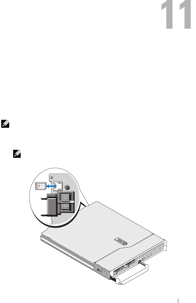
Configuring a VFlash Media Card for Use With iDRAC6 201
Configuring a VFlash Media Card for
Use With iDRAC6
The VFlash media card is a Secure Digital (SD) card that plugs into the
optional iDRAC6 Enterprise card slot at the back corner of the system.
It provides storage space that behaves like a common USB Flash Key device.
Installing a VFlash Media Card
NOTE: Dell-branded vFlash media is required for the virtual flash partition.
1
Remove the blade from the chassis.
2
Locate the VFlash media slot at the back corner of the system.
NOTE: You do not need to remove the blade cover to install or remove
the card.

202 Configuring a VFlash Media Card for Use With iDRAC6
3
With the label side facing up, insert the contact-pin end of the SD card
into the card slot on the module.
NOTE: The slot is keyed to ensure correct insertion of the card.
4
Press inward on the card to lock it into the slot.
5
Place the blade back in the chassis.
Removing a VFlash Media Card
To remove the VFlash media, push inward on the card to release it, and pull
the card from the card slot.
Configuring the VFlash Media Card Using the
iDRAC6 Web Interface
Enabling or Disabling the VFlash Media Card
NOTE: The VFlash Enable check box is active only if a VFlash card is present.
If card is not present, the following message displays:
SD Card not inserted. Please insert an SD card of
size greater than 256MB.
1
Ensure that the VFlash card has been installed.
2
Open a supported Web browser window.
3
Log in to the iDRAC6 Web interface.
4
In the system tree, select
System
.
5
Click the
VFlash
tab.
The
VFlash
screen appears.
6
Select the
Enable VFlash
check box to enable the VFlash Media Card.
To disable, deselect the check box.
7
Click
Apply
.

Configuring a VFlash Media Card for Use With iDRAC6 203
Formatting the VFlash Media Card
NOTE: The Format option is active only if a VFlash card is present.
1
Log in to the iDRAC6 Web interface.
2
In the system tree, select
System
.
3
Click the
VFlash
tab.
The
VFlash
screen appears.
4
Ensure that VFlash is disabled. The
VFlash Enable
check box should be
cleared (unchecked).
5
Click
Format
.
An alert box appears, warning that any existing image on the card will be
erased during formatting and requesting confirmation. Click
OK
to continue.
A status bar appears, indicating formatting progress.
Uploading Disk Image
1
Ensure the image file has the extension .img and that the image is not
larger than 256 MB.
NOTE: Though your VFlash card may be larger than 256 MB, only 256 MB is
accessible at this time.
2
Log in to the iDRAC6 Web interface.
3
In the system tree, select
System
.
4
Click the
VFlash
tab.
The
VFlash
screen appears.
5
Ensure that VFlash is disabled. The
VFlash Enable
check box should be
cleared (unchecked).
6
In the
VFlash Drive
section, enter the path to the image file or click
Browse
to navigate to its location on your system.
Click
Upload
.
A status bar appears, indicating upload progress.
Viewing the VFlash Key Size
The Virtual Flash Key Size drop-down menu displays the current size setting.

204 Configuring a VFlash Media Card for Use With iDRAC6
Configuring the VFlash Media Card Using
RACADM
Enabling or Disabling the VFlash Media Card
Open a local console to the server, log in, and enter:
racadm cfgRacVirtual cfgVirMediaKeyEnable [
1
or
0
]
where 1 is enabled and 0 is disabled.
NOTE: For more information about cfgRacVirtual, including output details, see
"cfgRacVirtual."
Formatting the VFlash Media Card
Open a Telnet/SSH text console to the server, log in, and enter:
racadm vmkey reset
CAUTION: Formatting the VFlash media card deletes all existing data.
NOTE: For more information about vmkey, see "vmkey."
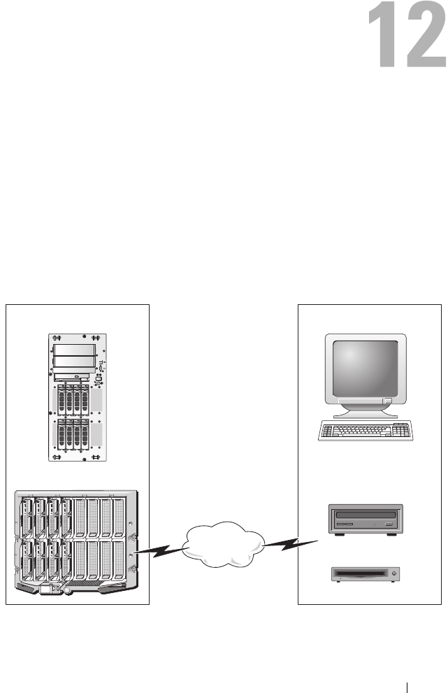
Configuring and Using Virtual Media 205
Configuring and Using Virtual Media
Overview
The Virtual Media feature, accessed through the console redirection viewer,
provides the managed server access to media connected to a remote system
on the network. Figure 12-1 shows the overall architecture of Virtual Media.
Figure 12-1. Overall Architecture of Virtual Media
Managed Server Management Station
Modular Server
Remote CD/DVD/USB
Remote Floppy
Network
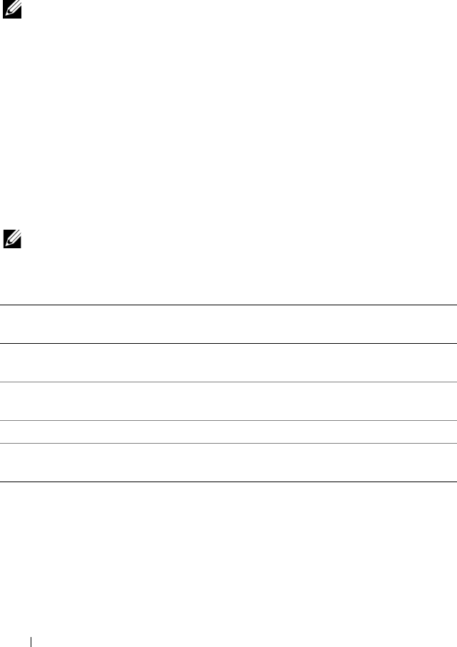
206 Configuring and Using Virtual Media
Using Virtual Media, administrators can remotely boot their managed
servers, install applications, update drivers, or even install new operating
systems remotely from the virtual CD/DVD and diskette drives.
NOTE: Virtual media requires a minimum available network bandwidth of 128 Kbps.
Virtual media defines two devices for the managed server’s operating system
and BIOS: a floppy disk device and an optical disk device.
The management station provides the physical media or image file across the
network. When Virtual Media is connected, all virtual CD/floppy drive
access requests from the managed server are directed to the management
station across the network. Connecting Virtual Media appears the same as
inserting media into physical devices. When virtual media is not connected,
virtual devices on the managed server appear as two drives without media
installed in the drives.
Table 12-1 lists the supported drive connections for virtual floppy and virtual
optical drives.
NOTE: Changing Virtual Media while connected could stop the system
boot sequence.
Windows-Based Management Station
To run the Virtual Media feature on a management station running the
Windows operating system, install a supported version of Internet Explorer
with the ActiveX Control plug-in (see "Supported Web Browsers"). Set the
browser security to Medium or a lower setting to enable Internet Explorer to
download and install signed ActiveX controls.
Table 12-1. Supported Drive Connections
Supported Virtual Floppy Drive
Connections
Supported Virtual Optical Drive
Connections
Legacy 1.44 floppy drive with a 1.44
floppy diskette
CD-ROM, DVD, CDRW, combination
drive with CD-ROM media
USB floppy drive with a 1.44 floppy
diskette
CD-ROM/DVD image file in the ISO9660
format
1.44 floppy image USB CD-ROM drive with CD-ROM media
USB removable disk (minimum size
128 MB)

Configuring and Using Virtual Media 207
Depending on your version of Internet Explorer, a custom security setting for
ActiveX may be required:
1
Start Internet Explorer.
2
Click
Tools
→
Internet Options
, and then click the
Security
tab.
3
Under
Select a Web content zone to specify its security settings
, click to
select the desired zone.
4
Under
Security level for this zone
, click
Custom Level
.
The
Security Settings
window appears.
5
Under
ActiveX controls and plugins
, ensure that the following settings are
set to
Enable
:
• Allow Scriptlets
• Automatic prompting for ActiveX controls
• Download signed ActiveX controls
• Download unsigned ActiveX controls
6
Click
OK
to save any changes and close the
Security Settings
window.
7
Click
OK
to close the
Internet Options
window.
8
Restart Internet Explorer.
You must have administrator rights to install ActiveX. Before installing the
ActiveX control, Internet Explorer may display a security warning.
To complete the ActiveX control installation procedure, accept the ActiveX
control when Internet Explorer prompts you with a security warning.
Linux-Based Management Station
To run the virtual media feature on a management station running the Linux
operating system, install a supported version of Firefox. See "Supported Web
Browsers" for more information.
A Java Runtime Environment (JRE) is required is required to run the console
redirection plugin. You can download a JRE from java.sun.com. JRE
version 1.6 or above is recommended.

208 Configuring and Using Virtual Media
Configuring Virtual Media
1
Log in to the iDRAC6 Web interface.
2
Click the
Console/Media
tab.
3
Click
Configuration
, and then click
Virtual Media
.
The
Console Redirection Configuration
screen appears.
4
Click
Virtual Media
.
5
In the
Virtual Media
section, select values for the settings. See Table 12-2
for information on
Virtual Media
configuration values.
6
Click
Apply
to save your settings.
An alert dialog appears with the following message:
You are about
to change device configuration. All existing
redirection sessions will be closed. Do you want
to continue?
7
Click
OK
to continue.
An alert dialog appears with the following message:
Virtual Media
Configuration successfully set.
Table 12-2. Virtual Media Configuration Values
Attribute Value
Attach Virtual Media Attach — Immediately attaches Virtual Media to the
server.
Detach — Immediately detaches Virtual Media from
the server.
Auto-Attach — Attaches Virtual Media to the server
only when a virtual media session is started.
Maximum Sessions Displays the maximum number of Virtual Media
sessions allowed. This value is always 1.
NOTE: Only one virtual media user session is allowed;
however, multiple devices can be attached in a single
session. See "Running Virtual Media."
Active Sessions Displays the current number of Virtual Media sessions.

Configuring and Using Virtual Media 209
Running Virtual Media
CAUTION: Do not issue a racreset command when running a Virtual Media
session. Otherwise, undesirable results may occur, including data loss.
NOTE: The Console Viewer window application must remain active while you
access the virtual media.
1
Open a supported Web browser on your management station.
2
Log in to the iDRAC6 Web interface.
Virtual Media Encryption
Enabled
Enables (checked) or disables (not checked)
encryption on Virtual Media connections.
Virtual Media Port Number The network port number used for connecting to the
Virtual Media service without encryption.
Two consecutive ports starting from the port number
specified are used to connect to the Virtual Media
service. The port number following the specified port
must not be configured for any other iDRAC6 service.
The default is 3668.
Virtual Media SSL Port
Number
The network port number used for encrypted
connections to the Virtual Media service.
Two consecutive ports starting from the port number
specified are used to connect to the Virtual Media
service. The port number following the specified port
must not be configured for any other iDRAC6 service.
The default is 3670.
Floppy Emulation Indicates whether the Virtual Media appears as a
floppy drive or as a USB key to the server. If Floppy
Emulation is checked, the Virtual Media device
appears as a floppy device on the server. If it is
unchecked, it appears as a USB Key drive.
Enable Boot Once Enables (checked) or disables (not checked) the
boot-once option, which automatically terminates the
Virtual Media session after the server has booted once.
This option is useful for automated deployments.
Table 12-2. Virtual Media Configuration Values (continued)
Attribute Value

210 Configuring and Using Virtual Media
3
Click the
Console/Media
tab.
The
Console Redirection and Virtual Media
screen appears.
To change the values of any of the displayed attributes, see "Configuring
Virtual Media."
NOTE: The Floppy Image File under Floppy Drive (if applicable) may appear,
as this device can be virtualized as a virtual floppy. You can select one optical
drive and one floppy at the same time, or a single drive.
NOTE: The virtual device drive letters on the managed server do not coincide
with the physical drive letters on the management station.
NOTE: Virtual Media may not function properly on Windows operating system
clients that are configured with Internet Explorer Enhanced Security.
To resolve this issue, see your Microsoft operating system documentation or
contact your administrator.
4
Click
Launch Viewer
.
NOTE: On Linux, the file jviewer.jnlp is downloaded to your desktop and a
dialog box will ask what to do with the file. Choose the option to Open with
program and then select the javaws application, which is located in the bin
subdirectory of your JRE installation directory.
The
iDRACView
application launches in a separate window.
5
Select
Media
→
Virtual Media Wizard…
The
Media Redirection Wizard
appears.
6
View the
Status
window at the bottom of the
Wizard
screen. If media is
connected, you must disconnect it before connecting a different media
source. To disconnect media, click the
Disconnect
button next to the
media in the
Status
window.
7
Select the radio button next to the media types you want to connect.
You can select both the
Floppy Image
radio button and one of the radio
buttons in the
CD/DVD Drive
section.
To connect a floppy image or ISO image, enter the path to the image
location on your local computer, or click the
Browse
button to navigate to
the image location.

Configuring and Using Virtual Media 211
8
Click the
Connect
button next to each selected media type
.
The media is connected and the
Status
window is updated.
9
Click
Close
.
Disconnecting Virtual Media
1
Select
Media
→
Virtual Media Wizard…
The
Media Redirection Wizard
appears.
2
Click
Disconnect
next to the
media you wish to disconnect.
The media is disconnected and the
Status
window is updated.
3
Click
Close
.
Booting From Virtual Media
The system BIOS enables you to boot from virtual optical drives or virtual
floppy drives. During POST, enter the BIOS setup window and verify that the
virtual drives are enabled and listed in the correct order.
To change the BIOS setting, perform the following steps:
1
Boot the managed server.
2
Press <F2> to enter the BIOS setup window.
3
Scroll to the boot sequence and press <Enter>.
In the pop-up window, the virtual optical drives and virtual floppy drives
are listed with the standard boot devices.
4
Ensure that the virtual drive is enabled and listed as the first device with
bootable media. If required, follow the on-screen instructions to modify
the boot order.
5
Save the changes and exit.
The managed server reboots.
The managed server attempts to boot from a bootable device based on the
boot order. If the virtual device is connected and a bootable media is
present, the system boots to the virtual device. Otherwise, the system
overlooks the device—similar to a physical device without bootable media.

212 Configuring and Using Virtual Media
Installing Operating Systems Using Virtual Media
This section describes a manual, interactive method to install the operating
system on your management station that may take several hours to complete.
A scripted operating system installation procedure using Virtual Media may
take fewer than 15 minutes to complete. See "Deploying the Operating
System" for more information.
1
Verify the following:
• The operating system installation DVD/CD is inserted in the
management station’s DVD/CD drive.
• The local DVD/CD drive is selected.
• You are connected to the virtual drives.
2
Follow the steps for booting from the virtual media in the "Booting From
Virtual Media" section to ensure that the BIOS is set to boot from the
DVD/CD drive from which you are installing.
3
Follow the on-screen instructions to complete the installation.
Using Virtual Media When the Server’s Operating System Is Running
Windows-Based Systems
On Windows systems, the virtual media drives are automounted if they are
attached and configured with a drive letter.
Using the virtual drives from within Windows is similar to using your physical
drives. When you connect to the media using the Virtual Media wizard,
the media is available at the system by clicking the drive and browsing
its content.
Linux-Based Systems
Depending on the configuration of the software on your system, the virtual
media drives may not be automounted. If your drives are not automounted,
manually mount the drives using the Linux mount command.

Configuring and Using Virtual Media 213
Frequently Asked Questions
Table 12-3 lists frequently asked questions and answers.
Table 12-3. Using Virtual Media: Frequently Asked Questions
Question Answer
Sometimes, I notice my
Virtual Media client
connection drop. Why?
When a network time-out occurs, iDRAC6
firmware drops the connection, disconnecting the
link between the server and the Virtual Drive.
If the Virtual Media configuration settings are
changed in the iDRAC6 Web interface or by local
RACADM commands, any connected media is
disconnected when the configuration change
is applied.
To reconnect to the Virtual Drive, use the Virtual
Media wizard.
Which operating systems
support iDRAC6?
See "Supported Operating Systems" for a list of
supported operating systems.
Which Web browsers support
iDRAC6?
See "Supported Web Browsers" for a list of
supported Web browsers.
Why do I sometimes lose my
client connection?
• You can sometimes lose your client connection if
the network is slow or if you change the CD in the
client system CD drive. For example, if you
change the CD in the client system’s CD drive,
the new CD might have an autostart feature.
If this is the case, the firmware can time out and
the connection can be lost if the client system
takes too long before it is ready to read the CD.
If a connection is lost, reconnect from the
GUI and continue the previous operation.
• When a network timeout occurs, iDRAC6
firmware drops the connection, disconnecting the
link between the server and the Virtual Drive.
Also, someone may have altered the Virtual Media
configuration settings in the Web interface or by
entering RADACM commands. To reconnect to
the Virtual Drive, use the
Virtual Media
feature.

214 Configuring and Using Virtual Media
An installation of the Windows
operating system seems to take
too long. Why?
If you are installing the Windows operating system
using the Dell PowerEdge Installation and Server
Management CD and a slow network connection,
the installation procedure may require an extended
amount of time to access the iDRAC6 Web
interface due to network latency. While the
installation window does not indicate the
installation progress, the installation procedure is
in progress.
I am viewing the contents of a
floppy drive or USB memory key.
If I try to establish a Virtual
Media connection using the
same drive, I receive a
connection failure message and
am asked to retry. Why?
Simultaneous access to Virtual Floppy drives is not
allowed. Close the application used to view the
drive contents before you attempt to virtualize
the drive.
How do I configure my virtual
device as a bootable device?
On the managed server, access the BIOS Setup and
navigate to the boot menu. Locate the virtual CD,
Virtual Floppy, or Virtual Flash and change the
device boot order as needed. For example, to boot
from a CD drive, configure the CD drive as the
first drive in the boot order.
Table 12-3. Using Virtual Media: Frequently Asked Questions (continued)
Question Answer

Configuring and Using Virtual Media 215
What types of media can I boot
from?
iDRAC6 allows you to boot from the following
bootable media:
• CDROM/DVD Data media
• ISO 9660 image
• 1.44 Floppy disk or floppy image
• A USB key that is recognized by the operating
system as a removable disk (minimum size 128
MB)
• A USB key image
How can I make my USB key
bootable?
Search support.dell.com for the Dell Boot Utility, a
Windows program you can use to make your Dell
USB key bootable.
You can also boot with a Windows 98 startup disk
and copy system files from the startup disk to your
USB key. For example, from the DOS prompt,
enter the following command:
sys a:
x
: /s
where x: is the USB key you want to make bootable.
You can also use the Dell boot utility to create a
bootable USB key. This utility is only compatible
with Dell-branded USB keys. To download the
utility, open a Web browser, navigate to the Dell
Support website located at support.dell.com,
and search for R122672.exe.
Table 12-3. Using Virtual Media: Frequently Asked Questions (continued)
Question Answer

216 Configuring and Using Virtual Media
I cannot locate my Virtual
Floppy device on a system
running Red Hat® Enterprise
Linux® or the SUSE® Linux
operating system. My Virtual
Media is attached and I am
connected to my remote floppy.
What should I do?
Some Linux versions do not automount the Virtual
Floppy Drive and the Virtual CD drive in a similar
manner. To mount the Virtual Floppy Drive,
locate the device node that Linux assigns to the
Virtual Floppy Drive. Perform the following
steps to correctly find and mount the Virtual
Floppy Drive:
1
Open a Linux command prompt and run the
following command:
grep "Virtual Floppy" /var/log/
messages
2
Locate the last entry to that message and note the
time.
3
At the Linux prompt, run the following
command:
grep "
hh:mm:ss
" /var/log/messages
where:
hh:mm:ss
is the time stamp of the message
returned by grep in step 1.
4
In step 3, read the result of the grep command
and locate the device name that is given to the
Dell Virtual Floppy.
5
Ensure that you are attached and connected to
the Virtual Floppy Drive.
6
At the Linux prompt, run the following
command:
mount
/dev/sdx
/mnt/floppy
where:
/dev/sdx
is the device name found in step 4
/mnt/floppy
is the mount point.
Table 12-3. Using Virtual Media: Frequently Asked Questions (continued)
Question Answer

Configuring and Using Virtual Media 217
What file system types are
supported on my Virtual
Floppy Drive?
Your Virtual Floppy Drive supports FAT16 or
FAT32 file systems.
When I performed a firmware
update remotely using the
iDRAC6 Web interface, my
virtual drives at the server were
removed. Why?
Firmware updates cause iDRAC6 to reset, drop the
remote connection, and unmount the virtual
drives. The drives will reappear when the iDRAC6
reset is complete.
Table 12-3. Using Virtual Media: Frequently Asked Questions (continued)
Question Answer

218 Configuring and Using Virtual Media

Using the Local RACADM Command Line Interface 219
Using the Local RACADM Command
Line Interface
The local RACADM command line interface (CLI) provides access to
iDRAC6 management features from the managed server. RACADM provides
access to the same features as the iDRAC6 Web interface. However,
RACADM can be used in scripts to ease configuration of multiple servers and
iDRACs, where the Web interface is more useful for interactive management.
Local RACADM commands do not use network connections to access
iDRAC6 from the managed server. This means that you can use local
RACADM commands to configure the initial iDRAC6 networking.
For more information about configuring multiple iDRACs, see "Configuring
Multiple iDRACs."
This section provides the following information:
• Using RACADM from a command prompt
• Configuring iDRAC6 using the
racadm
command
• Using the RACADM configuration file to configure multiple iDRACs
Using the RACADM Command
You run RACADM commands locally (on the managed server) from a
command prompt or shell prompt.
Log in to the managed server, start a command shell, and enter local
RACADM commands in the following format:
racadm <
subcommand
> -g <
group
> -o <
object
> <
value
>
Without options, the RACADM command displays general use information.
To display the RACADM subcommand list, enter:
racadm help

220 Using the Local RACADM Command Line Interface
The subcommand list includes all commands that are supported by iDRAC6.
To get help for a subcommand, enter:
racadm help <
subcommand
>
The command displays the syntax and command-line options for the
subcommand.
RACADM Subcommands
Table 13-1 provides a description of each RACADM subcommand that you
can run in RACADM. For a detailed listing of RACADM subcommands
including syntax and valid entries, see "RACADM Subcommand Overview."
Table 13-1. RACADM Subcommands
Command Description
clrasrscreen Clears the last crash (ASR) screen.
clrraclog Clears the iDRAC6 log. After clearing, a single entry is made
to indicate the user and time that the log was cleared.
clrsel Clears the managed server’s System Event Log entries.
config Configures iDRAC6.
getconfig Displays the current iDRAC6 configuration properties.
getniccfg Displays the current IP configuration for the controller.
getraclog Displays the iDRAC6 log.
getractime Displays the iDRAC6 time.
getssninfo Displays information about active sessions.
getsvctag Displays service tags.
getsysinfo Displays information about iDRAC6 and the managed server,
including IP configuration, hardware model, firmware
versions, and operating system information.
gettracelog Displays the iDRAC6 trace log. If used with -i, the
command displays the number of entries in the iDRAC6
trace log.
help Lists iDRAC6 subcommands.
help <subcommand> Lists usage statement for the specified subcommand.

Using the Local RACADM Command Line Interface 221
Using the RACADM Utility to Configure iDRAC6
This section describes how to use RACADM to perform various iDRAC6
configuration tasks.
Displaying Current iDRAC6 Settings
The RACADM getconfig subcommand retrieves current configuration
settings from iDRAC6. The configuration values are organized into groups
containing one or more objects, and the objects have values.
See "iDRAC6 Enterprise Property Database Group and Object Definitions"
for a complete description of the groups and objects.
To display a list of all iDRAC6 groups, enter this command:
racadm getconfig -h
To display the objects and values for a particular group, enter this command:
racadm getconfig -g
<
group
>
localconredirdisable Performs local kVM disable from the local system.
racreset Resets iDRAC6.
racresetcfg Resets iDRAC6 to the default configuration.
serveraction Performs power management operations on the
managed server.
setniccfg Sets the IP configuration for the controller.
sslcertdownload Downloads a CA certificate.
sslcertupload Uploads a CA certificate or server certificate to iDRAC6.
sslcertview Views a CA certificate or server certificate in iDRAC6.
sslcsrgen Generates and downloads the SSL CSR.
testemail Forces iDRAC6 to send an e-mail over the iDRAC6 NIC.
testtrap Forces iDRAC6 to send an SNMP alert over the
iDRAC6 NIC.
vmkey Resets the virtual media key to the default size of 256MB.
Table 13-1. RACADM Subcommands (continued)
Command Description

222 Using the Local RACADM Command Line Interface
For example, to display a list of all cfgLanNetworking group object settings,
enter the following command:
racadm getconfig -g cfgLanNetworking
Managing iDRAC6 Users with RACADM
NOTE: Use caution when using the racresetcfg command, as all configuration
parameters are reset to the original defaults. Any previous changes are lost.
NOTE: If you are configuring a new iDRAC6 or if you ran the racadm racresetcfg
command, the only current user is root with the password calvin.
NOTE: Users can be enabled and disabled over time. As a result, a user may have a
different index number on each iDRAC6.
NOTE: Users and groups created for Active Directory environments must conform
to the Active Directory naming convention.
You can configure up to 15 users in the iDRAC6 property database.
(A sixteenth user is reserved for the IPMI LAN user.) Before you manually
enable an iDRAC6 user, verify if any current users exist.
To verify if a user exists, enter the following command at the command prompt:
racadm getconfig -u <
username
>
OR
enter the following command once for each index from 1 to 16:
racadm getconfig -g cfgUserAdmin -i <
index
>
NOTE: You can also enter racadm getconfig -f <
filename
> and view
the generated <filename> file, which includes all users, as well as all other iDRAC6
configuration parameters.
Several parameters and object IDs are displayed with their current values.
Two objects of interest are:
# cfgUserAdminIndex=
nn
cfgUserAdminUserName=

Using the Local RACADM Command Line Interface 223
If the cfgUserAdminUserName object has no value, that index number,
which is indicated by the cfgUserAdminIndex object, is available for use. If a
name appears after the =, that index is assigned to that user name.
NOTE: Users and groups created for Active Directory environments must conform
to the Active Directory naming convention.
Adding an iDRAC6 User
To add a new user to iDRAC6, perform the following steps:
1
Set the user name.
2
Set the password.
3
Set the Login to iDRAC6 user privilege.
4
Enable the user.
Example
The following example describes how to add a new user named "John" with a
"123456" password and login privileges to iDRAC6:
racadm config -g cfgUserAdmin -o cfgUserAdminUserName
-i 2 john
racadm config -g cfgUserAdmin -o cfgUserAdminPassword
-i 2 123456
racadm config -g cfgUserAdmin -o cfgUserPrivilege -i 2
0x00000001
racadm config -g cfgUserAdmin -o cfgUserAdminEnable
-i 2 1
To verify the new user, use one of the following commands:
racadm getconfig -u john
racadm getconfig –g cfgUserAdmin –i 2

224 Using the Local RACADM Command Line Interface
Enabling an iDRAC6 User With Permissions
To grant a user a specific administrative (role-based) permissions, set the
cfgUserAdminPrivilege property to a bitmask constructed from the values
show in Table 13-2:
For example, to allow the user Configure iDRAC, Configure Users, Clear
Logs, and Access Console Redirection privileges, add the values 0x00000002,
0x00000004, 0x00000008, and 0x00000010 to construct the bitmap
0x0000002E. Then enter the following command to set the privilege:
racadm config -g cfgUserAdmin -o
cfgUserAdminPrivilege -i
2 0x0000002E
Removing an iDRAC6 User
When using RACADM, users must be disabled manually and on an
individual basis. Users cannot be deleted by using a configuration file.
The following example illustrates the command syntax that can be used to
delete a RAC user:
racadm config -g cfgUserAdmin -o cfgUserAdminUserName
-i <index> ""
Table 13-2. Bit Masks for User Privileges
User Privilege Privilege Bit Mask
Login to iDRAC6 0x0000001
Configure iDRAC6 0x0000002
Configure Users 0x0000004
Clear Logs 0x0000008
Execute Server Control Commands 0x0000010
Access Console Redirection 0x0000020
Access Virtual Media 0x0000040
Test Alerts 0x0000080
Execute Debug Commands 0x0000100

Using the Local RACADM Command Line Interface 225
A null string of double quote characters ("") instructs iDRAC6 to remove the
user configuration at the specified index and reset the user configuration to
the original factory defaults.
Testing E-mail Alerting
The iDRAC6 e-mail alert feature allows users to receive e-mail alerts when a
critical event occurs on the managed server. The following example shows
how to test the e-mail alert feature to ensure that iDRAC6 can properly send
e-mail alerts across the network.
racadm testemail -i 2
NOTE: Ensure that the SMTP and E-mail Alert settings are configured before
testing the e-mail alert feature. See "Configuring E-Mail Alerts" for more
information.
Testing the iDRAC6 SNMP Trap Alert Feature
The iDRAC6 SNMP trap alerting feature allows SNMP trap listener
configurations to receive traps for system events that occur on the
managed server.
The following example shows how a user can test the SNMP trap alert feature.
racadm testtrap -i 2
NOTE: Before you test the iDRAC6 SNMP trap alerting feature, ensure that the
SNMP and trap settings are configured correctly. See the testtrap and testemail
subcommand descriptions to configure these settings.
Configuring iDRAC6 Network Properties
To generate a list of available network properties, enter the following:
racadm getconfig -g cfgLanNetworking
To use DHCP to obtain an IP address, use the following command to write
the object cfgNicUseDhcp and enable this feature:
racadm config -g cfgLanNetworking -o cfgNicUseDHCP 1
The commands provide the same configuration functionality as the iDRAC6
Configuration Utility when you are prompted to press <Ctrl><E>. For
more information about configuring network properties with the iDRAC6
Configuration Utility, see "iDRAC6 LAN."

226 Using the Local RACADM Command Line Interface
The following is an example of how the command may be used to configure
desired LAN network properties.
racadm config -g cfgLanNetworking -o cfgNicEnable 1
racadm config -g cfgLanNetworking -o cfgNicIpAddress
192.168.0.120
racadm config -g cfgLanNetworking -o cfgNicNetmask
255.255.255.0
racadm config -g cfgLanNetworking -o cfgNicGateway
192.168.0.120
racadm config -g cfgLanNetworking -o cfgNicUseDHCP 0
racadm config -g cfgLanNetworking -o
cfgDNSServersFromDHCP 0
racadm config -g cfgLanNetworking -o cfgDNSServer1
192.168.0.5
racadm config -g cfgLanNetworking -o cfgDNSServer2
192.168.0.6
racadm config -g cfgLanNetworking -o
cfgDNSRegisterRac 1
racadm config -g cfgLanNetworking -o cfgDNSRacName
RAC-EK00002
racadm config -g cfgLanNetworking -o
cfgDNSDomainNameFromDHCP 0
racadm config -g cfgLanNetworking -o cfgDNSDomainName
MYDOMAIN
NOTE: If cfgNicEnable is set to 0, the iDRAC6 LAN is disabled even if DHCP is
enabled.

Using the Local RACADM Command Line Interface 227
Configuring IPMI Over LAN
1
Configure IPMI over LAN by entering the following command:
racadm config -g cfgIpmiLan -o cfgIpmiLanEnable 1
NOTE: This setting determines the IPMI commands that can be executed from the
IPMI over LAN interface. For more information, see the IPMI 2.0 specifications.
a
Update the IPMI channel privileges by entering the following
command:
racadm config -g cfgIpmiLan -o
cfgIpmiLanPrivilegeLimit
<level>
where
<level>
is one of the following:
•
2
(
User
)
•
3
(
Operator
)
•
4
(
Administrator
)
For example, to set the IPMI LAN channel privilege to 2 (User), enter
the following command:
racadm config -g cfgIpmiLan -o
cfgIpmiLanPrivilegeLimit 2
b
Set the IPMI LAN channel encryption key, if required, using a
command such as the following:
NOTE: The iDRAC6 IPMI supports the RMCP+ protocol. See the IPMI 2.0
specifications for more information.
racadm config -g cfgIpmiLan -o
cfgIpmiEncryptionKey
<key>
where <
key
> is a 20-character encryption key in a valid
hexadecimal format.

228 Using the Local RACADM Command Line Interface
2
Configure IPMI Serial over LAN (SOL) using the following command:
racadm config -g cfgIpmiSol -o cfgIpmiSolEnable 1
NOTE: The IPMI SOL minimum privilege level determines the minimum
privilege required to activate IPMI SOL. For more information, see the IPMI 2.0
specification.
a
Update the IPMI SOL minimum privilege level using the following
command:
racadm config -g cfgIpmiSol -o
cfgIpmiSolMinPrivilege
<level>
where
<level>
is one of the following:
•
2
(
User
)
•
3
(
Operator
)
•
4
(
Administrator
)
For example, to configure the IPMI privileges to 2 (User), enter the
following command:
racadm config -g cfgIpmiSol -o
cfgIpmiSolMinPrivilege 2
NOTE: To redirect the serial console over LAN, ensure that the SOL baud rate
is identical to your managed server’s baud rate.
b
Update the IPMI SOL baud rate using the following command:
racadm config -g cfgIpmiSol -o
cfgIpmiSolBaudRate
<baud-rate>
where
<baud-rate>
is 19200, 57600, or 115200 bps.
For example:
racadm config -g cfgIpmiSol -o
cfgIpmiSolBaudRate 57600
c
Enable SOL by typing the following command at the command prompt.
NOTE: SOL can be enabled or disabled for each individual user.
racadm config -g cfgUserAdmin -o
cfgUserAdminSolEnable -i
<id>
2
where
<id>
is the user’s unique ID.

Using the Local RACADM Command Line Interface 229
Configuring PEF
You can configure the action you wish iDRAC6 to take for each platform alert.
Table 13-3 lists the possible actions and the value to identify them in RACADM.
1
Configure PEF actions using the following command:
racadm config -g cfgIpmiPef -o cfgIpmiPefAction
-i
<
index
> <
action-value
>
where <
index
> is the PEF index (Table 5-7), and <
action-value
> is a
value from Table 13-3.
For example, to enable PEF to reboot the system and send an IPMI alert
when a processor critical event is detected, enter the following command:
racadm config -g cfgIpmiPef -o cfgIpmiPefAction
-i 9 2
Configuring PET
1
Enable global alerts using the following command:
racadm config -g cfgIpmiLan -o
cfgIpmiLanAlertEnable 1
2
Enable PET using the following command:
racadm config -g cfgIpmiPet -o
cfgIpmiPetAlertEnable -i <
index
> <0|1>
where
<
index
> is the PET destination index and
0
or
1
disable PET or
enable PET, respectively.
For example, to enable PET with index 4, enter the following command:
racadm config -g cfgIpmiPet -o
cfgIpmiPetAlertEnable -i 4 1
Table 13-3. Platform Event Action
Action Value
No action 0
Power off 1
Reboot 2
Power Cycle 3

230 Using the Local RACADM Command Line Interface
3
Configure your PET policy using the following command:
racadm config -g cfgIpmiPet -o
cfgIpmiPetAlertDestIPAddr -i <
index
>
<IP-address>
where <
index
> is the PET destination index and <
IP-address
> is the
destination IP address of the system that receives the platform event alerts.
4
Configure the Community Name string.
At the command prompt, enter:
racadm config -g cfgIpmiLan -o
cfgIpmiPetCommunityName
<name>
where <
name
> is the PET Community Name.
Configuring E-mail Alerts
1
Enable global alerts by entering the following command:
racadm config -g cfgIpmiLan -o
cfgIpmiLanAlertEnable 1
2
Enable e-mail alerts by entering the following commands:
racadm config -g cfgEmailAlert -o
cfgEmailAlertEnable -i <
index
> <0|1>
where <
index
> is the e-mail destination index and 0 disables the e-mail
alert or 1 enables the alert. The e-mail destination index can be a value
from 1 through 4.
For example, to enable e-mail with index 4, enter the following command:
racadm config -g cfgEmailAlert -o
cfgEmailAlertEnable -i 4 1
3
Configure your e-mail settings by entering the following command:
racadm config -g cfgEmailAlert -o
cfgEmailAlertAddress -i 1
<email-address>
where 1 is the e-mail destination index and <
email-address
> is the
destination e-mail address that receives the platform event alerts.

Using the Local RACADM Command Line Interface 231
4
To configure a custom message, enter the following command:
racadm config -g cfgEmailAlert -o
cfgEmailAlertCustomMsg -i <
index
>
<custom-message>
where <
index
> is the e-mail destination index and <
custom-message
> is
the custom message.
5
Test the configured e-mail alert, if desired, by entering the following
command:
racadm testemail -i <
index
>
where <
index
> is the e-mail destination index to test.
Configuring IP Filtering (IP Range)
IP address filtering (or IP Range Checking) allows iDRAC6 access only
from clients or management workstations whose IP addresses are within a
user-specified range. All other login requests are denied.
IP filtering compares the IP address of an incoming login to the IP address
range that is specified in the following cfgRacTuning properties:
• cfgRacTuneIpRangeAddr
• cfgRacTuneIpRangeMask
The cfgRacTuneIpRangeMask property is applied to both the incoming
IP address and to the cfgRacTuneIpRangeAddr properties. If the results are
identical, the incoming login request is allowed to access iDRAC6.
Logins from IP addresses outside this range receive an error.
The login proceeds if the following expression equals zero:
cfgRacTuneIpRangeMask & (
<incoming-IP-address>
^
cfgRacTuneIpRangeAddr)
where & is the bitwise AND of the quantities and ^ is the bitwise exclusive-
OR.
See "cfgRacTuning" for a complete list of cfgRacTuning properties.

232 Using the Local RACADM Command Line Interface
Configuring IP Filtering
To configure IP filtering in the Web interface, follow these steps:
1
Click
System
→
Remote Access
→
iDRAC
→
Network/Security
.
2
On the
Network Configuration
screen, click
Advanced Settings
.
3
Check the
IP Range Enabled
checkbox and enter the
IP Range Address
and
IP Range Subnet Mask
.
4
Click
Apply
.
Table 13-4. IP Address Filtering (IPRange) Properties
Property Description
cfgRacTuneIpRangeEnable Enables the IP range checking feature.
cfgRacTuneIpRangeAddr Determines the acceptable IP address bit pattern,
depending on the 1’s in the subnet mask.
This property is bitwise anded with
cfgRacTuneIpRangeMask to determine the upper
portion of the allowed IP address. Any IP address that
contains this bit pattern in its upper bits is allowed to
log in. Logins from IP addresses that are outside this
range fail. The default values in each property allow
an address range from 192.168.1.0 to 192.168.1.255
to log in.
cfgRacTuneIpRangeMask Defines the significant bit positions in the IP address.
The mask should be in the form of a netmask,
where the more significant bits are all 1’s with a
single transition to all zeros in the lower-order bits.

Using the Local RACADM Command Line Interface 233
Following are examples using local RACADM to set up IP filtering.
NOTE: See "Using the Local RACADM Command Line Interface" for more
information about RACADM and RACADM commands.
1
The following RACADM commands block all IP addresses except
192.168.0.57:
racadm config -g cfgRacTuning -o
cfgRacTuneIpRangeEnable 1
racadm config -g cfgRacTuning -o
cfgRacTuneIpRangeAddr 192.168.0.57
racadm config -g cfgRacTuning -o
cfgRacTuneIpRangeMask 255.255.255.255
2
To restrict logins to a small set of four adjacent IP addresses (for example,
192.168.0.212 through 192.168.0.215), select all but the lowest two bits in
the mask, as shown below:
racadm config -g cfgRacTuning -o
cfgRacTuneIpRangeEnable 1
racadm config -g cfgRacTuning -o
cfgRacTuneIpRangeAddr 192.168.0.212
racadm config -g cfgRacTuning -o
cfgRacTuneIpRangeMask 255.255.255.252
The last byte of the range mask is set to 252, the decimal equivalent of
11111100b.
IP Filtering Guidelines
Use the following guidelines when enabling IP filtering:
• Ensure that
cfgRacTuneIpRangeMask
is configured in the form of a
netmask, where all most significant bits are 1’s (which defines the subnet
in the mask) with a transition to all 0’s in the low-order bits.
• Use the desired range’s base address as the value of
cfgRacTuneIpRangeAddr
. The 32-bit binary value of this address should
have zeros in all the low-order bits where there are zeros in the mask.

234 Using the Local RACADM Command Line Interface
Configuring IP Blocking
IP blocking dynamically determines when excessive login failures occur from
a particular IP address and blocks (or prevents) the address from logging in to
iDRAC6 for a preselected time span.
The IP blocking features include:
• The number of allowed login failures (
cfgRacTuneIpBlkFailcount
)
• The time frame in seconds during which these failures must occur
(
cfgRacTuneIpBlkFailWindow
)
• The amount of time in seconds that the blocked IP address is prevented
from establishing a session after the allowed number of failures is exceeded
(
cfgRacTuneIpBlkPenaltyTime
)
As login failures accumulate from a specific IP address, they are registered by
an internal counter. When the user logs in successfully, the failure history is
cleared and the internal counter is reset.
NOTE: When login attempts are refused from the client IP address, some SSH clients
may display the following message: ssh exchange identification:
Connection closed by remote host.
See "iDRAC6 Enterprise Property Database Group and Object Definitions"
for a complete list of cfgRacTune properties.
"Log In Retry Restriction (IP Blocking) Properties" lists the user-defined
parameters.
Table 13-5. Log In Retry Restriction (IP Blocking) Properties
Property Definition
cfgRacTuneIpBlkEnable Enables the IP blocking feature.
When consecutive failures
(cfgRacTuneIpBlkFailCount) from a single
IP address are encountered within a specific amount
of time (cfgRacTuneIpBlkFailWindow), all further
attempts to establish a session from that address are
rejected for a certain time span
(cfgRacTuneIpBlkPenaltyTime).
cfgRacTuneIpBlkFailCount Sets the number of login failures from an IP address
before the login attempts are rejected.

Using the Local RACADM Command Line Interface 235
Enabling IP Blocking
The following example prevents a client IP address from establishing a session
for five minutes if that client has failed five login attempts in a one-minute
period of time.
racadm config -g cfgRacTuning -o
cfgRacTuneIpRangeEnable 1
racadm config -g cfgRacTuning -o
cfgRacTuneIpBlkFailCount 5
racadm config -g cfgRacTuning -o
cfgRacTuneIpBlkFailWindow 60
racadm config -g cfgRacTuning -o
cfgRacTuneIpBlkPenaltyTime 300
The following example prevents more than three failed attempts within one
minute, and prevents additional login attempts for an hour.
racadm config -g cfgRacTuning -o
cfgRacTuneIpBlkEnable 1
racadm config -g cfgRacTuning -o
cfgRacTuneIpBlkFailCount 3
racadm config -g cfgRacTuning -o
cfgRacTuneIpBlkFailWindow 60
racadm config -g cfgRacTuning -o
cfgRacTuneIpBlkPenaltyTime 360
cfgRacTuneIpBlkFailWindow The time frame in seconds during which the failure
attempts are counted. When the failures exceed
this limit, they are dropped from the counter.
cfgRacTuneIpBlkPenaltyTime Defines the time span in seconds that login
attempts from an IP address with excessive failures
are rejected.
Table 13-5. Log In Retry Restriction (IP Blocking) Properties (continued)
Property Definition

236 Using the Local RACADM Command Line Interface
Configuring iDRAC6 Telnet and SSH Services Using Local RACADM
The telnet/SSH console can be configured locally (on the managed server)
using RACADM commands.
NOTE: You must have Configure iDRAC6 permission to execute the commands in
this section.
NOTE: When you reconfigure telnet or SSH settings in iDRAC6, any current
sessions are terminated without warning.
To enable telnet and SSH from the local RACADM, log in to the managed
server and enter the following commands at a command prompt:
racadm config -g cfgSerial -o cfgSerialTelnetEnable 1
racadm config -g cfgSerial -o cfgSerialSshEnable 1
To disable the telnet or SSH service, change the value from 1 to 0:
racadm config -g cfgSerial -o cfgSerialTelnetEnable 0
racadm config -g cfgSerial -o cfgSerialSshEnable 0
Enter the following command to change the telnet port number on iDRAC6:
racadm config -g cfgRacTuning -o cfgRacTuneTelnetPort
<new port number>
For example, to change the telnet port from the default 22 to 8022, enter this
command:
racadm config -g cfgRacTuning -o cfgRacTuneTelnetPort
8022
For a complete list of available RACADM CLI commands, see "Using the
Local RACADM Command Line Interface."
Using an iDRAC6 Configuration File
An iDRAC6 configuration file is a text file that contains a representation of
the values in the iDRAC6 database. You can use the RACADM getconfig
subcommand to generate a configuration file containing the current values
from iDRAC6. You can then edit the file and use the RACADM config -f
subcommand to load the file back into iDRAC6, or to copy the configuration
to other iDRACs.

Using the Local RACADM Command Line Interface 237
Creating an iDRAC6 Configuration File
The configuration file is a plain text file. You can use any valid file name;
however, the .cfg file extension is the recommended convention.
The configuration file can be:
• Created with a text editor
• Obtained from iDRAC6 with the RACADM
getconfig
subcommand
• Obtained from iDRAC6 with the RACADM
getconfig
subcommand and
then edited
To obtain a configuration file, with the RACADM getconfig command,
enter the following command at a command prompt on the managed server:
racadm getconfig -f myconfig.cfg
This command creates the file myconfig.cfg in the current directory.
Configuration File Syntax
NOTE: Edit the configuration file with a plain text editor, such as Notepad on
Windows or vi on Linux. The racadm utility parses ASCII text only. Any formatting
confuses the parser and may corrupt the iDRAC6 database.
This section describes the format of the configuration file.
• Lines that start with
#
are comments.
A comment
must
start in the first column of the line. A
#
character in any
other column is treated as a normal # character.
Example
:
#
#
This is a comment
[cfgUserAdmin]
cfgUserAdminPrivilege=4
• Group entries must be surrounded by
[
and
]
characters.
The starting
[
character denoting a group name
must
start in column one.
This group name
must
be specified before any of the objects in that group.
Objects that do not include an associated group name generate an error.

238 Using the Local RACADM Command Line Interface
The configuration data is organized into groups as defined in "iDRAC6
Enterprise Property Database Group and Object Definitions."
The following example displays a group name, object, and the object’s
property value.
Example:
[cfgLanNetworking]
(
group name
)
cfgNicIpAddress=143.154.133.121
(
object name
)
• Parameters are specified as
object=value
pairs with no white space between
the object, =, and value.
White space that is included after the value is ignored. White space inside
a value string remains unmodified. Any character to the right of the
=
is
taken as is (for example, a second
=
, or a
#
,
[
,
]
, and so forth).
• The parser ignores an index object entry.
Yo u
cannot
specify which index is used. If the index already exists, it is
either used or the new entry is created in the first available index for
that group.
The
racadm getconfig -f
<filename>
command places
a comment in front of index objects, allowing you to see the
included comments.
NOTE: You can create an indexed group manually using the following command:
racadm config -g <groupName> -o <anchored-object> -i <index> <unique-anchor-
name>.
• The line for an indexed group
cannot
be deleted from a configuration file.
You must remove an indexed object manually using the following
command:
racadm config -g <
groupName
> -o <
objectName
> -i
<
index
> ""
NOTE: A NULL string (identified by two
""
characters) directs iDRAC6 to delete the
index for the specified group.
To view the contents of an indexed group, use the following command:
racadm getconfig -g <
groupName
> -i <
index
>

Using the Local RACADM Command Line Interface 239
• For indexed groups the object anchor
must
be the first object after the
[ ]
pair. The following are examples of the current indexed groups:
[cfgUserAdmin]
cfgUserAdminUserName=<
username
>
• If the parser encounters an indexed group, it is the value of the anchored
object that differentiates the various indexes.
The parser reads in all of the indexes from iDRAC6 for that group.
Any objects within that group are simple modifications when iDRAC6 is
configured. If a modified object represents a new index, the index is
created on iDRAC6 during configuration.
• You cannot specify a desired index in a configuration file.
Indexes may be created and deleted, so over time the group may become
fragmented with used and unused indexes. If an index is present, it is
modified. If an index is not present, the first available index is used.
This method allows flexibility when adding indexed entries where you do
not need to make exact index matches between all the RACs being
managed. New users are added to the first available index. A configuration
file that parses and runs correctly on one iDRAC6 may not run correctly on
another if all indexes are full and you must add a new user.
Modifying the iDRAC6 IP Address in a Configuration File
When you modify the iDRAC6 IP address in the configuration file, remove all
unnecessary <variable>=<value> entries. Only the actual variable group’s
label with "[" and "]" remains, including the two <variable>=<value>
entries pertaining to the IP address change.
For example:
#
# Object Group "cfgLanNetworking"
#
[cfgLanNetworking]
cfgNicIpAddress=10.35.10.110
cfgNicGateway=10.35.10.1

240 Using the Local RACADM Command Line Interface
This file will be updated as follows:
#
# Object Group "cfgLanNetworking"
#
[cfgLanNetworking]
cfgNicIpAddress=10.35.9.143
# comment, the rest of this line is ignored
cfgNicGateway=10.35.9.1
Loading the Configuration File Into iDRAC6
The command racadm config -f <
filename
> parses the
configuration file to verify that valid group and object names are present and
that syntax rules are followed. If the file is error-free the command then
updates the iDRAC6 database with the contents of the file.
NOTE: To verify the syntax only and not update the iDRAC6 database, add the -c
option to the config subcommand.
Errors in the configuration file are flagged with the line number and a
message that explains the problem. You must correct all errors before the
configuration file can update iDRAC6.
NOTE: Use the racresetcfg subcommand to reset the database and the iDRAC6 NIC
settings to the original default settings and remove all users and user
configurations. While the root user is available, other users’ settings are also reset
to the default settings.
Before you execute the racadm config -f <
filename
> command,
you can run the racresetcfg subcommand to reset iDRAC6 to its default
settings. Ensure that the configuration file you will load includes all desired
objects, users, indexes, and other parameters.
To update iDRAC6 with the configuration file, execute the following
command at the managed server’s command prompt:
racadm config -f <
filename>
After the command has completed, you can execute the RACADM getconfig
subcommand to confirm that the update succeeded.

Using the Local RACADM Command Line Interface 241
Configuring Multiple iDRACs
Using a configuration file, you can configure other iDRACs with identical
properties. Follow these steps to configure multiple iDRACs:
1
Create the configuration file from the iDRAC6 settings you want to
replicate to the others. At a command prompt on the managed server,
enter the following command:
racadm getconfig -f <
filename
>
where <
filename
> is the name of a file to save the iDRAC6 properties,
such a
myconfig.cfg
.
See "Creating an iDRAC6 Configuration File" for more information.
NOTE: Some configuration files contain unique iDRAC6 information (such as the
static IP address) that must be modified before you export the file to other iDRACs.
2
Edit the configuration file you created in the previous step and remove or
comment-out any settings you
do not
want to replicate.
3
Copy the edited configuration file to a network drive where it is accessible
to each managed server whose iDRAC6 you want to configure.
4
For each iDRAC6 you want to configure:
a
Log in to the managed server and start a command prompt.
b
If you want to reconfigure iDRAC6 from the default settings, enter
the following command:
racadm racreset
c
Load the configuration file into iDRAC6 with the following
command:
racadm config -f <
filename
>
where <
filename
> is the name of the configuration file you created.
Include the full path if the file is not in the working directory.
d
Reset the iDRAC6 that was configured by entering the following
command:
racadm reset

242 Using the Local RACADM Command Line Interface

Using iDRAC6 Enterprise SM-CLP Command Line Interface 243
Using iDRAC6 Enterprise
SM-CLP Command Line Interface
This section provides information about the Server Management Workgroup
(SMWG) Server Management-Command Line Protocol (SM-CLP) that is
incorporated in iDRAC6.
NOTE: This section assumes that you are familiar with the Systems Management
Architecture for Server Hardware (SMASH) Initiative and the SMWG SM-CLP
specifications. For more information on these specifications, see the Distributed
Management Task Force (DMTF) website at www.dmtf.org.
The iDRAC6 SM-CLP is a protocol driven by the DMTF and SMWG to
provide standards for systems management CLI implementations. Many
efforts are driven by a defined SMASH architecture that is targeted as a
foundation for more standardized systems management set of components.
The SMWG SM-CLP is a subcomponent of the overall SMASH efforts
driven by DMTF.
SM-CLP provides a subset of the functionality provided by the local
RACADM command line interface, but with a different access path. SM-CLP
executes within iDRAC6, while RACADM executes on the managed server.
Also, RACADM is a Dell proprietary interface, where SM-CLP is an industry
standard interface. See "RACADM and SM-CLP Equivalencies" for a
mapping of the RACADM and SM-CLP commands.
System Management With SM-CLP
The iDRAC6 SM-CLP enables you to manage the following system features
from a command line or script:
• Server Power Management — Turn on, shutdown, or reboot the system
• System Event Log (SEL) Management — Display or clear the SEL records
• iDRAC6 user account management

244 Using iDRAC6 Enterprise SM-CLP Command Line Interface
• Active Directory configuration
• iDRAC6 LAN configuration
• SSL Certificate Signature Request (CSR) generation
• Virtual media configuration
• Serial over LAN (SOL) redirection over Telnet or SSH
iDRAC6 SM-CLP Support
SM-CLP is hosted from iDRAC6 firmware, and supports telnet and SSH
connections. The iDRAC6 SM-CLP interface is based on the SM-CLP
Specification Version 1.0 provided by the DMTF organization.
The following sections provide an overview of the SM-CLP feature that is
hosted from iDRAC6.
SM-CLP Features
The SM-CLP specification provides a common set of standard SM-CLP verbs
that can be used for simple systems management through the CLI.
SM-CLP promotes the concept of verbs and targets to provide system
configuration capabilities through the CLI. The verb indicates the operation
to perform and the target determines the entity (or object) that runs the
operation.
The following is the syntax of the SM-CLP command line:
<verb> [<options>] [<target>] [<properties>]

Using iDRAC6 Enterprise SM-CLP Command Line Interface 245
Table 14-1 provides a list of the verbs the iDRAC6 CLI supports, the syntax of
each command, and a list of the options the verb supports.
Table 14-1. Supported SM-CLP CLI Verbs
Verb Description Options
cd Navigates through the managed system address
space using the shell.
Syntax:
cd [
options
] [
target
]
–default, –examine, –
help, –output, –version
delete Deletes an object instance.
Syntax:
delete [
options
]
target
–examine, –help, –
output, –version
dump Moves a binary image from the MAP to a URI.
dump -destination <
URI
> [
options
]
[
target
]
–destination, –examine,
–help, –output, –
version
exit Exits from the SM-CLP shell session.
Syntax:
exit [
options
]
–help, –output, –
version
help Displays help for SM-CLP commands.
help
-examine, -help,
-output, -version
load Moves a binary image to the MAP from a URI.
Syntax:
load -source <
URI
> [
options
]
[
target
]
–examine, –help, –
output, –source, –
version
reset Resets the target.
Syntax:
reset [
options
] [
target
]
–examine, –help, –
output, –version
set Sets the properties of a target
Syntax:
set [
options
] [
target
]
<
property name
>=<
value
>
–examine, –help, –
output, –version

246 Using iDRAC6 Enterprise SM-CLP Command Line Interface
Table 14-2 describes the SM-CLP options. Some options have abbreviated
forms, as shown in the table.
show Displays the target properties, verbs, and
subtargets.
Syntax:
show [
options
] [
target
]
<
property name
>=<
value
>
-all, -default, –display, –
examine, –help, –level,
–output, –version
start Starts a target.
Syntax:
start [
options
] [
target
]
–examine, –force, –
help, –output, –version
stop Shuts down a target.
Syntax:
stop [
options
] [
target
]
–examine, –force, –
help, –output, –version,
–wait
version Displays the version attributes of a target.
Syntax:
version [
options
]
–examine, –help, –
output, –version
Table 14-2. Supported SM-CLP Options
SM-CLP Option Description
–all, –a Instructs the verb to perform all possible functions.
-destination Specifies the location to store an image in the dump
command.
Syntax:
-destination <URI>
-display, -d Filters the command output.
Syntax:
-display <properties | targets | verbs>[,
<properties | targets | verbs>]*
Table 14-1. Supported SM-CLP CLI Verbs (continued)
Verb Description Options

Using iDRAC6 Enterprise SM-CLP Command Line Interface 247
Navigating the MAP Address Space
NOTE: The slash (/) and backslash (\) are interchangeable in SM-CLP address
paths. However, a backslash at the end of a command line continues the command
on the next line and is ignored when the command is parsed.
Objects that can be managed with SM-CLP are represented by targets
arranged in a hierarchical space called the Manageability Access Point (MAP)
address space. An address path specifies the path from the root of the address
space to an object in the address space.
The root target is represented by a slash (/) or a backslash (\). It is the default
starting point when you log in to iDRAC6. Navigate down from the root using
the cd verb. For example to navigate to the third record in the System Event
Log (SEL), enter the following command:
->cd /system1/sp1/logs1/record3
-examine, -x Instructs the command processor to validate the command
syntax without executing the command.
–help, –h Displays help for the verb.
–level, -l Instructs the verb to operate on targets at additional levels
beneath the specified target.
Syntax:
-level <
n
| all>
–output, –o Specifies the format for the output.
Syntax:
-output <text | clpcsv | clpxml>
-source Specifies the location of an image in a load command.
Syntax:
-source <URI>
–version, –v Displays the SMASH-CLP version number.
Table 14-2. Supported SM-CLP Options (continued)
SM-CLP Option Description

248 Using iDRAC6 Enterprise SM-CLP Command Line Interface
Enter the cd verb with no target to find your current location in the address
space. The .. and . abbreviations work as they do in Windows and Linux:
.. refers to the parent level and . refers to the current level.
Targets
Table 14-3 provides a list of targets available through the SM-CLP.
Table 14-3. SM-CLP Targets
Target Definition
/system1/ The managed system target.
/system1/sp1 The service processor.
/system1/sol1 Serial over LAN target.
/system1/sp1/account1 through /
system1/sp1/account16
The sixteen local iDRAC6 user accounts.
account1 is the root account.
/system1/sp1/enetport1 The iDRAC6 NIC MAC address.
/system1/sp1/enetport1/lanendpt1/
ipendpt1
The iDRAC6 IP, gateway, and netmask settings.
/system1/sp1/enetport1/lanendpt1/
ipendpt1/dnsendpt1
The iDRAC6 DNS server settings.
/system1/sp1/group1 through /
system1/sp1/group5
The Active Directory standard schema groups.
/system1/sp1/logs1 The log collections target.
/system1/sp1/logs1/record1 An individual SEL record instance on the
managed system.
/system1/sp1/logs1/records The SEL target on the managed system.
/system1/sp1/oemdell_racsecurity1 Storage for parameters used to generate a
Certificate Signing Request.
/system1/sp1/oemdell_ssl1 SSL certificate request state.
/system1/sp1/oemdell_vmservice1 The virtual media configuration and state.

Using iDRAC6 Enterprise SM-CLP Command Line Interface 249
Using the Show Verb
To learn more about a target use the show verb. This verb displays the
target’s properties, sub-targets, and a list of the SM-CLP verbs that are
allowed at that location.
Using the -display Option
The show –display option allows you to limit the output of the command to
one or more of properties, targets, and verbs. For example, to display just the
properties and targets at the current location, use the following command:
show -d properties,targets /system1/sp1/account1
To list only certain properties, qualify them, as in the following command:
show -d properties=(userid,username) /system1/sp1/
account1
If you only want to show one property, you can omit the parentheses.
Using the -level Option
The show -level option executes show over additional levels beneath the
specified target. For example, if you want to see the username and userid
properties of the account1 through account16 targets beneath /system1/sp1,
you could enter the following command:
show -l 1 -d properties=(userid,username) /system1/
sp1/account*
To see all targets and properties in the address space, use the -l all option,
as in the following command:
show -l all -d properties /
Using the -output Option
The -output option specifies one of four formats for the output of SM-CLP
verbs: text, clpcsv, keyword, and clpxml.
The default format is text, and is the most readable output. The clpcsv
format is a comma-separated values format suitable for loading into a
spreadsheet program. The keyword format outputs information as a list of
keyword=value pairs one per line. The clpxml format is an XML document

250 Using iDRAC6 Enterprise SM-CLP Command Line Interface
containing a response XML element. The DMTF has specified the clpcsv and
clpxml formats and their specifications can be found on the DMTF website
at www.dmtf.org.
The following example shows how to output the contents of the SEL in XML:
show -l all -output format=clpxml /system1/sp1/logs1
iDRAC6 SM-CLP Examples
The following subsections provide examples for using the SM-CLP to
perform the following operations:
• Server power management
• SEL management
• MAP target navigation
• Display system properties
• Setting the iDRAC6 IP address, subnet mask, and gateway address
For information on the use of the iDRAC6 SM-CLP interface, see "iDRAC6
SM-CLP Property Database."
Server Power Management
Table 14-4 provides examples of using SM-CLP to perform power
management operations on a managed server.
Table 14-4. Server Power Management Operations
Operation Syntax
Logging in to
iDRAC6 using the
SSH interface
>ssh 192.168.0.120
>login: root
>password:
Power down the
server
->stop /system1
system1 has been stopped successfully
Power up the server
from a powered-off
state
->start /system1
system1 has been started successfully
Reboot the server ->reset /system1
system1 has been reset successfully

Using iDRAC6 Enterprise SM-CLP Command Line Interface 251
SEL Management
Table 14-5 provides examples of using the SM-CLP to perform SEL-related
operations on the managed system.
Table 14-5. SEL Management Operations
Operation Syntax
Viewing the
SEL
->show /system1/sp1/logs1
Targets:
record1
record2
record3
record4
record5
Properties:
Description=IPMI SEL
MaxNumberOfRecords=512
CurrentNumberOfRecords=5
Verbs:
cd
delete
exit
help
show
version

252 Using iDRAC6 Enterprise SM-CLP Command Line Interface
Viewing the
SEL record
->show /system1/sp1/logs1/record4
ufip=/system1/sp1/logs1/log1/record4
Properties:
Caption=Not defined
Description=Backplane Drive 0: drive slot
sensor for Backplane, drive presence was
asserted
ElementName=Not Supported
LogCreationClassName=CIM_RecordLog
LogName=IPMI SEL
CreationClassName=CIM_LogRecord
RecordID=4
MessageTimeStamp=16:37:10,January 13,2007
Verbs:
cd
exit
help
show
version
Clearing the
SEL
->delete /system1/sp1/logs1
All records deleted successfully
Table 14-5. SEL Management Operations (continued)
Operation Syntax

Using iDRAC6 Enterprise SM-CLP Command Line Interface 253
MAP Target Navigation
Table 14-6 provides examples of using the cd verb to navigate the MAP. In all
examples, the initial default target is assumed to be /.
Setting the iDRAC6 IP Address, Subnet Mask, and Gateway Address
Using SM-CLP to update the iDRAC6 network properties is a two-part
process:
1
Set new values for the NIC properties at location
/system1/sp1/enetport1/
lanendpt1/ipendpt1:
–
oemdell_nicenable
— Set to
1
to enable iDRAC6 networking,
0
to
disable iDRAC6 networking
–
ipaddress
— The IP address
–
subnetmask
— The subnet mask
–
oemdell_usedhcp
— Set to
1
to enable using DHCP to set the
ipaddress
and
subnetmask
properties,
0
to set static values
2
Commit the new values by setting the
committed
property to
1
.
Table 14-6. Map Target Navigation Operations
Operation Syntax
Navigate to the
system target and
reboot
->cd system1
->reset
NOTE: The current default target is /.
Navigate to the SEL
target and display the
log records
->cd system1
->cd sp1
->cd logs1
->show
->cd system1/sp1/logs1
->show
Display current target ->cd .
Move up one level ->cd ..
Exiting the shell ->exit

254 Using iDRAC6 Enterprise SM-CLP Command Line Interface
Whenever the commit property has the value of 1, the current settings of the
properties are active. When you change any of the properties, the commit
property is reset to 0 to indicate that the values have not been committed.
NOTE: The commit property only affects the properties at the
/system1/sp1/
enetport1/lanendpt1/ipendpt1
MAP location. All other SM-CLP commands take
effect immediately.
NOTE: If you use local RACADM to set the iDRAC6 network properties, your
changes take affect immediately because local RACADM does not depend upon a
network connection.
When you commit the changes, the new network settings take effect, which
causes your telnet or ssh session to be terminated. By introducing the commit
step, you can delay the termination of your session until you have completed
all of your SM-CLP commands.
Table 14-7 provides examples of setting the iDRAC6 properties using SM-CLP.
Table 14-7. Setting iDRAC6 Networking Properties with SM-CLP
Operation Syntax
Navigate to the
iDRAC6 NIC
properties location
->cd /system1/sp1/enetport1/lanendpt1/
ipendpt1
Set the new IP
address
->set ipaddress=10.10.10.10
Set the subnet
mask
->set subnetmask=255.255.255.255
Turn on the DHCP
flag
->set oemdell_usedhcp=1
Enable the NIC ->set oemdell_nicenable=1
Commit the
changes
->set committed=1

Using iDRAC6 Enterprise SM-CLP Command Line Interface 255
Updating iDRAC6 Firmware Using SM-CLP
To update iDRAC6 firmware using SM-CLP, you must know the TFTP URI
for the Dell update package.
Follow these steps to update the firmware using SM-CLP:
1
Log in to iDRAC6 using telnet or SSH.
2
Check the current firmware version by entering the following command:
version
3
Enter the following command:
load -source tftp://<
tftp-server
>/<
update-path
> /
system1/sp1
where <
tftp-server
> is the DNS name or IP address of your TFTP server
and <
update-path
> is the path to the update package on the TFTP server.
Your telnet or SSH session will be terminated. You may need to wait several
minutes for the firmware update to complete.
4
To verify that the new firmware was written, start a new telnet or SSH
session and re-enter the version command again.

256 Using iDRAC6 Enterprise SM-CLP Command Line Interface

Deploying Your Operating System Using iVMCLI 257
Deploying Your Operating System
Using iVMCLI
The Integrated Virtual Media Command Line Interface (iVMCLI) utility is a
command-line interface that provides virtual media features from the
management station to iDRAC6 in the remote system. Using iVMCLI and
scripted methods, you can deploy your operating system on multiple remote
systems in your network.
This section provides information on integrating the iVMCLI utility into your
corporate network.
Before You Begin
Before using the iVMCLI utility, ensure that your targeted remote systems
and corporate network meet the requirements listed in the following sections.
Remote System Requirements
• iDRAC6 is configured in each remote system.
Network Requirements
A network share must contain the following components:
• Operating system files
• Required drivers
• Operating system boot image file(s)
The image file must be an operating system CD or a CD/DVD ISO image
with an industry-standard, bootable format.

258 Deploying Your Operating System Using iVMCLI
Creating a Bootable Image File
Before you deploy your image file to the remote systems, ensure that a
supported system can boot from the file. To test the image file, transfer the
image file to a test system using the iDRAC6 Web user interface and then
reboot the system.
The following sections provide specific information for creating image files
for Linux and Windows systems.
Creating an Image File for Linux Systems
Use the Data Duplicator (dd) utility to create a bootable image file for your
Linux system.
To run the utility, open a command prompt and enter the following:
dd if=
<input-device>
of=
<output-file>
For example:
dd if=/dev/sdc0 of=mycd.img
Creating an Image File for Windows Systems
When choosing a data replicator utility for Windows image files, select a
utility that copies the image file and the CD/DVD boot sectors.
Preparing for Deployment
Configuring the Remote Systems
1
Create a network share that can be accessed by the management station.
2
Copy the operating system files to the network share.
3
If you have a bootable, preconfigured deployment image file to deploy the
operating system to the remote systems, skip this step.
If you do not have a bootable, preconfigured deployment image file, create
the file. Include any programs and/or scripts used for the operating system
deployment procedures.
For example, to deploy a Microsoft
®
Windows
®
operating system, the
image file may include programs that are similar to deployment methods
used by Microsoft Systems Management Server (SMS).

Deploying Your Operating System Using iVMCLI 259
When you create the image file, do the following:
• Follow standard network-based installation procedures.
• Mark the deployment image as "read only" to ensure that each target
system boots and executes the same deployment procedure.
4
Perform one of the following procedures:
• Integrate
IPMItool
and the Virtual Media command line interface
(iVMCLI) into your existing operating system deployment
application. Use the sample
ivmdeploy
script as a guide to using
the utility.
• Use the existing
ivmdeploy
script to deploy your operating system.
Deploying the Operating System
Use the iVMCLI utility and the ivmdeploy script included with the utility to
deploy the operating system to your remote systems.
Before you begin, review the sample ivmdeploy script included with the
iVMCLI utility. The script shows the detailed steps needed to deploy the
operating system to remote systems in your network.
The following procedure provides a high-level overview for deploying the
operating system on targeted remote systems.
1
List the iDRAC6 IP addresses of the remote systems that will be deployed
in the
ip.txt
text file, one IP address per line.
2
Insert a bootable operating system CD or DVD into the client media drive.
3
Run
ivmdeploy
at the command line.
To run the ivmdeploy script, enter the following command at the command
prompt:
ivmdeploy -r ip.txt -u <
idrac-user
> -p <
idrac-passwd
>
-c {<
iso9660-img>
| <
path>
}
where:
•<
idrac-user
> is the iDRAC6 user name—for example,
root
•<
idrac-passwd
> is the password for the iDRAC6 user—for example,
calvin

260 Deploying Your Operating System Using iVMCLI
•<
iso9660-img
> is the path to an ISO9660 image of the operating system
installation CD or DVD
•<
path
> is the path to the device containing the operating system
installation CD or DVD
The ivmdeploy script passes its command line options to the iVMCLI utility.
See "Command Line Options" for details about these options. The script
processes the -r option slightly differently than the iVMCLI -r option. If the
argument to the -r option is the name of an existing file, the script reads
iDRAC6 IP addresses from the specified file and runs the iVMCLI utility
once for each line. If the argument to the -r option is not a filename, then it
should be the address of a single iDRAC6. In this case, the -r works as
described for the iVMCLI utility.
The ivmdeploy script supports installation only from a CD/DVD or a CD/
DVD ISO9660 image. If you need to install from a floppy disk or a floppy disk
image, you can modify the script to use the iVMCLI -f option.
Using the Virtual Media Command Line
Interface Utility
The Virtual Media Command Line Interface (iVMCLI) utility is a scriptable
command-line interface that provides virtual media features from the
management station to iDRAC6.
The iVMCLI utility provides the following features:
NOTE: When virtualizing read-only image files, multiple sessions may share
the same image media. When virtualizing physical drives, only one session
can access a given physical drive at a time.
• Removable media devices or image files that are consistent with the
Virtual Media plug-ins
• Automatic termination when the iDRAC6 firmware boot once option
is enabled
• Secure communications to iDRAC6 using Secure Sockets Layer (SSL)
Before you run the utility, ensure that you have Virtual Media user privilege
to iDRAC6.

Deploying Your Operating System Using iVMCLI 261
If your operating system supports administrator privileges or an operating
system-specific privilege or group membership, administrator privileges are
also required to run the iVMCLI command.
The client system’s administrator controls user groups and privileges,
thereby controlling the users who can run the utility.
For Windows systems, you must have Power User privileges to run the
iVMCLI utility.
For Linux systems, you can access the iVMCLI utility without administrator
privileges by using the sudo command. This command provides a centralized
means of providing non-administrator access and logs all user commands.
To add or edit users in the iVMCLI group, the administrator uses the visudo
command. Users without administrator privileges can add the sudo command
as a prefix to the iVMCLI command line (or to the iVMCLI script) to obtain
access to iDRAC6 in the remote system and run the utility.
Installing the iVMCLI Utility
The iVMCLI utility is located on the Dell Systems Management Tools and
Documentation DVD, which is included with your Dell OpenManage System
Management Software Kit. To install the utility, insert the DVD into your
system, and follow the on-screen instructions.
The Dell Systems Management Tools and Documentation DVD contains the
latest systems management software products, including diagnostics, storage
management, remote access service, and the RACADM utility. This DVD also
contains readme files, which provide the latest systems management software
product information.
The Dell Systems Management Tools and Documentation DVD also includes
ivmdeploy—a sample script that illustrates how to use the iVMCLI and
RACADM utilities to deploy software to multiple remote systems.
NOTE: The ivmdeploy script is dependent upon the other files that are present in its
directory when it is installed. If want to use the script from another directory, you
must copy all of the files with it.

262 Deploying Your Operating System Using iVMCLI
Command Line Options
The iVMCLI interface is identical on both Windows and Linux systems.
The utility uses options that are consistent with the RACADM utility
options. For example, an option to specify the iDRAC6 IP address requires
the same syntax for both RACADM and iVMCLI utilities.
The iVMCLI command format is as follows:
iVMCLI
[parameter] [operating_system_shell_options]
Command-line syntax is case sensitive. See "iVMCLI Parameters" for more
information.
If the remote system accepts the commands and iDRAC6 authorizes the
connection, the command continues to run until either of the following
occurs:
• The iVMCLI connection terminates for any reason.
• The process is manually terminated using an operating system control.
For example, in Windows, you can use the Task Manager to terminate
the process.
iVMCLI Parameters
iDRAC6 IP Address
-r
<iDRAC-IP-address>[:<iDRAC-SSL-port>]
This parameter provides the iDRAC6 IP address and SSL port, which the
utility needs to establish a Virtual Media connection with the target iDRAC6.
If you enter an invalid IP address or DDNS name, an error message appears
and the command is terminated.
<iDRAC-IP-address> is a valid, unique IP address or the iDRAC6 Dynamic
Domain Naming System (DDNS) name (if supported). If <iDRAC-SSL-
port> is omitted, port 443 (the default port) is used. The optional SSL port is
not required unless you change the iDRAC6 default SSL port.
iDRAC6 User Name
-u
<iDRAC-user-name>
This parameter provides the iDRAC6 user name that will run Virtual Media.

Deploying Your Operating System Using iVMCLI 263
The <iDRAC-user-name> must have the following attributes:
• Valid user name
• iDRAC6 Virtual Media User permission
If iDRAC6 authentication fails, an error message appears and the command is
terminated.
iDRAC6 User Password
-p
<iDRAC-user-password>
This parameter provides the password for the specified iDRAC6 user.
If iDRAC6 authentication fails, an error message displays and the command
terminates.
Floppy/Disk Device or Image File
-f {
<device-name>
|
<image-file>
}
where <device-name> is a valid drive letter (for Windows systems) or a valid
device file name, including the mountable file system partition number, if
applicable (for Linux systems); and <image-file> is the filename and path of
a valid image file.
This parameter specifies the device or file to supply the virtual floppy/disk
media.
For example, an image file is specified as:
-f c:\temp\myfloppy.img (Windows system)
-f /tmp/myfloppy.img (Linux system)
If the file is not write-protected, Virtual Media may write to the image file.
Configure the operating system to write-protect a floppy image file that
should not be overwritten.
For example, a device is specified as:
-f a:\ (Windows system)
-f /dev/sdb4 # 4th partition on device /dev/sdb
(Linux system)
If the device provides a write-protection capability, use this capability to
ensure that Virtual Media will not write to the media.

264 Deploying Your Operating System Using iVMCLI
Omit this parameter from the command line if you are not virtualizing floppy
media. If an invalid value is detected, an error message displays and the
command terminates.
CD/DVD Device or Image File
-c {<
device-name
> | <
image-file
>}
where <device-name> is a valid CD/DVD drive letter (Windows systems) or
a valid CD/DVD device file name (Linux systems) and <image-file> is the
file name and path of a valid ISO-9660 image file.
This parameter specifies the device or file that will supply the virtual
CD/DVD-ROM media:
For example, an image file is specified as:
-c c:\temp\mydvd.img (Windows systems)
-c /tmp/mydvd.img (Linux systems)
For example, a device is specified as:
-c d:\ (Windows systems)
-c /dev/cdrom (Linux systems)
Omit this parameter from the command line if you are not virtualizing
CD/DVD media. If an invalid value is detected, an error message is listed and
the command terminates.
Specify at least one media type (floppy or CD/DVD drive) with the
command, unless only switch options are provided. Otherwise, an error
message displays and the command terminates and generates an error.
Version Display
-v
This parameter is used to display the iVMCLI utility version. If no other
non-switch options are provided, the command terminates without an error
message.

Deploying Your Operating System Using iVMCLI 265
Help Display
-h
This parameter displays a summary of the iVMCLI utility parameters. If no other
non-switch options are provided, the command terminates without error.
Manual Display
-m
This parameter displays a detailed “man page” for the iVMCLI utility,
including descriptions of all of the possible options.
Encrypted Data
-e
When this parameter is included in the command line, iVMCLI will use an
SSL-encrypted channel to transfer data between the management station and
iDRAC6 in the remote system. If this parameter is not included in the
command line, the data transfer is not encrypted.
iVMCLI Operating System Shell Options
The following operating system features can be used in the iVMCLI
command line:
• stderr/stdout redirection — Redirects any printed utility output to a file.
For example, using the greater-than character (>) followed by a filename
overwrites the specified file with the printed output of the iVMCLI utility.
NOTE: The iVMCLI utility does not read from standard input (stdin). As a
result, stdin redirection is not required.
• Background execution — By default, the iVMCLI utility runs in the
foreground. Use the operating system's command shell features to cause
the utility to run in the background. For example, under a Linux operating
system, the ampersand character (&) following the command causes the
program to be spawned as a new background process.

266 Deploying Your Operating System Using iVMCLI
The latter technique is useful in script programs, as it allows the script to
proceed after a new process is started for the iVMCLI command (otherwise,
the script would block until the iVMCLI program is terminated).
When multiple iVMCLI instances are started in this way, and one or more of
the command instances must be manually terminated, use the operating
system-specific facilities for listing and terminating processes.
iVMCLI Return Codes
0 = No error
1 = Unable to connect
2 = iVMCLI command line error
3 = RAC firmware connection dropped
English-only text messages are also issued to standard error output whenever
errors are encountered.

Using the iDRAC6 Configuration Utility 267
Using the iDRAC6 Configuration
Utility
Overview
The iDRAC6 Configuration Utility is a pre-boot configuration environment
that allows you to view and set parameters for iDRAC6 and for the managed
server. Specifically, you can:
• View the firmware revision numbers for iDRAC6 and primary backplane
firmware
• Configure, enable, or disable the iDRAC6 local area network (LAN)
• Enable or disable IPMI Over LAN
• Configure LAN parameters
• Enable, disable, or cancel System Services
• Attach or detach the Virtual Media devices
• Change the administrative username and password
• Reset the iDRAC6 configuration to the factory defaults
• View System Event Log (SEL) messages or clear messages from the log
The tasks you can perform using iDRAC6 Configuration Utility can also be
performed using other utilities provided by the iDRAC6 or Dell OpenManage
software, including the Web-based interface, the SM-CLP command line
interface, the local RACADM command line interface and, in the case
of basic network configuration, at the iDRAC6 LCD during initial
iDRAC6 configuration.

268 Using the iDRAC6 Configuration Utility
Starting the iDRAC6 Configuration Utility
You must use an iDRAC6 KVM-connected console to access the iDRAC6
Configuration Utility initially or after a resetting iDRAC6 to the
default settings.
1
At the keyboard connected to the iDRAC6 KVM console, press <Print
Screen> to display the
iDRAC6 KVM On Screen Configuration and
Reporting (OSCAR)
menu. Use <Up Arrow> and <Down Arrow> to
highlight the slot containing your server, then press <Enter>.
2
Turn on or restart the server by pressing the power button on the front of
the server.
3
When you see the message
Press <Ctrl-E> for Remote
Access Setup within 5 sec.....
, immediately press
<Ctrl><E>.
The iDRAC6 Configuration Utility displays.
NOTE: If your operating system begins to load before you press <Ctrl><E>,
allow the system to finish booting, then restart your server and try again.
The first two lines of the Configuration Utility provide information about
iDRAC6 firmware and primary backplane firmware revisions. The revision
levels can be useful in determining whether a firmware upgrade is needed.
iDRAC6 firmware is the portion of the firmware concerned with external
interfaces, such as the Web-based interface, SM-CLP, and Web interfaces.
The primary backplane firmware is the portion of the firmware that interfaces
with and monitors the server hardware environment.
Using the iDRAC6 Configuration Utility
Beneath the firmware revision messages, the remainder of the iDRAC6
Configuration Utility is a menu of items that you can access by using the
up-arrow and down-arrow keys.
• If a menu item leads to a submenu or an editable text field, press
<Enter> to access the item and <Esc> to leave it when you have
finished configuring it.
• If an item has selectable values, such as Yes/No or Enabled/Disabled, press
the left-arrow or right-arrow keys or the spacebar to choose a value.
• If an item is not editable, it appears in blue. Some items become editable
depending upon other selections you make.

Using the iDRAC6 Configuration Utility 269
• The bottom line of the screen displays instructions for the current item.
You can press <F1> to display help for the current item.
• When you have finished using the iDRAC6 Configuration Utility,
press <Esc> to view the exit menu, where you can choose to save or
discard your changes or return to the utility.
The following sections describe the iDRAC6 Configuration Utility menu items.
iDRAC6 LAN
Use the left-arrow and right-arrow keys and the spacebar to select between
Enabled and Disabled.
The iDRAC6 LAN is disabled in the default configuration. The LAN must be
enabled to permit the use of iDRAC6 facilities, such as the Web-based
interface, telnet/SSH access to the SM-CLP command line interface, console
redirection, and virtual media.
If you choose to disable the LAN the following warning displays:
iDRAC Out-of-Band interface will be disabled if the
LAN Channel is OFF.
The message informs you that in addition to facilities that you access by
connecting to the iDRAC6 HTTP, HTTPS, telnet, or SSH ports directly,
out-of-band management network traffic, such as IPMI messages sent to
iDRAC6 from a management station, are not received when the LAN is
disabled. The local RACADM interface remains available and can be used to
reconfigure the iDRAC6 LAN.
Press any key to clear the message and continue.
IPMI Over LAN
Press the left-arrow and right-arrow keys and the spacebar to choose between
On and Off. When Off is selected, iDRAC6 will not accept IPMI messages
arriving over the LAN interface.
If you choose Off, the following warning displays:
iDRAC Out-of-Band interface will be disabled if IPMI
Over LAN is OFF.
Press any key to clear the message and continue. For an explanation of the
message, see "iDRAC6 LAN."

270 Using the iDRAC6 Configuration Utility
LAN Parameters
Press <Enter> to display the LAN Parameters submenu. When you have
finished configuring the LAN parameters, press <Esc> to return to the
previous menu.
Table 16-1. LAN Parameters
Item Description
RMCP+
Encryption Key
Press <Enter> to edit the value, <Esc> when finished.
The RMCP+ Encryption key is a 40-character hexadecimal
string (characters 0-9, a-f, and A-F). RMCP+ is an IPMI
extension that adds authentication and encryption to IPMI.
The default value is a string of 40 zeroes.
IP Address Source Select between DHCP and Static. When DHCP is selected,
the Ethernet IP Address, Subnet Mask, and Default Gateway
fields are obtained from a DHCP server. If no DHCP server is
found on the network, the fields are set to zeros.
When Static is selected, the Ethernet IP Address, Subnet
Mask, and Default Gateway items become editable.
Ethernet IP Address If the IP Address Source is set to DHCP, this field displays the
IP address obtained from DHCP.
If the IP Address Source is set to Static, enter the IP address
you wish to assign to the iDRAC.
The default is 192.168.0.120 plus the number of the slot
containing the server.
MAC Address This is the non-editable MAC address of the iDRAC6 network
interface.
Subnet Mask If the IP Address Source is set to DHCP, this field displays the
subnet mask address obtained from DHCP.
If the IP Address Source is set to Static, enter the subnet mask
for the iDRAC.
The default is 255.255.255.0.

Using the iDRAC6 Configuration Utility 271
Default Gateway If the IP Address Source is set to DHCP, this field displays the
IP address of the default gateway obtained from DHCP.
If the IP Address Source is set to Static, enter the IP address of
the default gateway.
The default is 192.168.0.1.
LAN Alert Enabled Select On to enable the Platform Event Trap (PET) LAN alert.
Alert Policy Entry 1 Select Enable or Disable to activate the first alert destination.
Alert Destination 1 Enter the IP address where PET LAN alerts will be forwarded.
Host Name String Press <Enter> to edit. Enter the name of the host for
PET alerts.
DNS Servers from
DHCP
Select On to retrieve DNS server addresses from a DHCP
service on the network. Select Off to specify the DNS server
addresses below.
DNS Server 1 If DNS Servers from DHCP is Off, enter the IP address of
the first DNS server.
DNS Server 2 If DNS Servers from DHCP is Off, enter the IP address of
the second DNS server.
Register iDRAC
Name
Select On to register the iDRAC6 name in the DNS service.
Select Off if you do not want users to be able to find the
iDRAC6 name in DNS.
iDRAC Name If Register iDRAC Name is set to On, press <Enter> to edit
the Current DNS iDRAC Name text field. Press <Enter>
when you have finished editing the iDRAC6 name. Press
<Esc> to return to the previous menu. The iDRAC6 name
must be a valid DNS host name.
Domain Name from
DHCP
Select On if you want to obtain the domain name from a
DHCP service on the network. Select Off if you want to specify
the domain name.
Domain Name If Domain Name from DHCP is Off, press <Enter> to edit
the Current Domain Name text field. Press <Enter> when
you have finished editing. Press <Esc> to return to the
previous menu. The domain name must be a valid DNS
domain, for example mycompany.com.
Table 16-1. LAN Parameters (continued)
Item Description

272 Using the iDRAC6 Configuration Utility
Virtual Media Configuration
Virtual Media
Use the left-arrow and right-arrow keys to select Attached or Detached.
• If you select
Attached
, the virtual media devices are attached to the USB
bus, making them available for use during
Console Redirection
sessions.
• If you select
Detached,
users cannot access virtual media devices during
Console Redirection
sessions.
NOTE: To use a USB Flash Drive with the Virtual Media feature, you must set USB
Flash Drive Emulation Type to Hard disk in the BIOS Setup Utility. Access the BIOS
Setup Utility by pressing <F2> during server start-up. If USB Flash Drive Emulation
Type is set to Auto, the Flash Drive appears as a floppy drive to the system.
Virtual Flash
Use the left-arrow and right-arrow keys to select Enabled or Disabled.
•
Enable
/
Disable
causes a
Detach
and an
Attach
of all Virtual Media
devices from the USB bus.
•
Disable
causes the Virtual Flash to be removed and to become unavailable
for use.
NOTE: This field will be read-only if an SD card of a size larger than 256 MB is not
present on AMEA card slot.
NOTE: Dell-branded vFlash media is required for the virtual flash partition.
System Services Configuration
System Services
Use the left-arrow and right-arrow keys to select Enabled or Disabled. If
enabled, certain iDRAC6 features can be configured through the Unified
Server Configuration (USC). For more information, see the Unified Server
Configurator User Guide, available on the Dell Support Website at
support.dell.com.
NOTE: Modifying this option restarts the server when you Save and Exit to apply
the new settings.
Using the iDRAC6 Configuration Utility 273
Cancel System Services
Use the left-arrow and right-arrow keys to select Yes or No.
When you select Yes, all Unified Server Configurator sessions are closed,
and the server restarts when you Save and Exit to apply the new settings.
LAN User Configuration
The LAN user is the iDRAC6 administrator account, which is root by default.
Press <Enter> to display the LAN User Configuration submenu. When you
have finished configuring the LAN user, press <Esc> to return to the
previous menu.
Reset to Default
Use the Reset to Default menu item to reset all of iDRAC6 configuration
items to the factory defaults. This may be required, for example, if you have
forgotten the administrative user password or if you want to reconfigure
iDRAC6 from the default settings.
NOTE: In the default configuration, iDRAC6 networking is disabled. You cannot
reconfigure the iDRAC6 over the network until you have enabled the iDRAC6
network in the iDRAC6 Configuration Utility.
Table 16-2. Lan User Configuration Screen
Item Description
Account Access Select Enabled to enable the administrator account.
Select Disabled to disable the administrator account.
Account Privilege Select between Admin, User, Operator, and No Access.
Account User Name Press <Enter> to edit the user name and press <Esc> when
you have finished. The default user name is root.
Enter Password Enter the new password for the administrator account.
The characters are not echoed on the display as you enter them.
Confirm Password Re-enter the new password for the administrator account.
If the characters you enter do not match the characters you
entered in the Enter Password field, a message displays and
you must re-enter the password.

274 Using the iDRAC6 Configuration Utility
Press <Enter> to select the item. The following warning message appears:
Resetting to factory defaults will restore remote Non-
Volatile user settings. Continue?
< NO (Cancel) >
< YES (Continue) >
To reset iDRAC6 to the defaults, select YES and press <Enter>.
System Event Log Menu
The System Event Log Menu allows you to view System Event Log (SEL)
messages and to clear the log messages. Press <Enter> to display the System
Event Log Menu. The system counts the log entries and then displays the
total number of records and the most recent message. The SEL retains a
maximum of 512 messages.
To view SEL messages, select View System Event Log and press <Enter>.
To navigate:
• Use the left-arrow key to move to the previous (older) message and the
right-arrow key to move to the next (newer) message.
• Enter a specific record number to jump to that record.
Press <Esc> to exit the System Event Log.
NOTE: You can only clear the SEL in the iDRAC6 Configuration Utility or in the
iDRAC6 Web-based interface.
To clear the SEL, select Clear the System Event Log and press <Enter>.
When you have finished with the SEL menu, press <Esc> to return to the
previous menu.
Exiting the iDRAC6 Configuration Utility
When you have finished making changes to iDRAC6 configuration, press the
<Esc> key to display the Exit menu.
Select Save Changes and Exit and press <Enter> to retain your changes.
Select Discard Changes and Exit and press <Enter> to ignore any changes
you made.
Select Return to Setup and press <Enter> to return to the iDRAC6
Configuration Utility.

Recovering and Troubleshooting the Managed Server 275
Recovering and Troubleshooting the
Managed Server
This section explains how to perform tasks related to diagnosing and
troubleshooting a remote managed server using iDRAC6 utilities. It contains
the following subsections:
• Trouble indications — Helps you to find messages and other system
indications that can lead to a diagnosis of the problem
• Problem-solving tools — Describes iDRAC6 tools that you can use to
troubleshoot your system
• Troubleshooting and frequently asked questions — Answers to typical
situations you may encounter
Safety First–For You and Your System
To perform certain procedures in this section, you must work with the chassis,
the PowerEdge server, or other hardware modules. Do not attempt to service
the system hardware except as explained in this guide and elsewhere in your
system documentation.
CAUTION: Many repairs may only be done by a certified service technician. You
should only perform troubleshooting and simple repairs as authorized in your
product documentation, or as directed by online or telephone service and support
team. Damage due to servicing that is not authorized by Dell is not covered by your
warranty. Read and follow the safety instructions that came with the product.

276 Recovering and Troubleshooting the Managed Server
Trouble Indicators
This section describes indications that there may be a problem with
your system.
LED Indicators
LEDs on the chassis or on components installed in the chassis are generally
the first indicators of system trouble. The following components and modules
have status LEDs:
• Chassis LCD display
• Servers
•Fans
•CMCs
• I/O modules
• Power supplies
The single LED on the chassis LCD summarizes the status of all of the
components in the system. A solid blue LED on the LCD indicates that no
fault conditions have been detected in the system. A blinking amber LED on
the LCD indicates that one or more fault conditions have been detected.
If the chassis LCD has a blinking amber LED, you can use the LCD menu to
locate the component that has a fault. See the Dell CMC Firmware User
Guide for help using the LCD.
Table 17-1 describes the meanings of the LED on the PowerEdge Server:
Table 17-1. Server LED Indicators
LED indicator Meaning
solid green The server is powered on. Absence of the green LED means the
server is not powered on.
solid blue iDRAC6 is healthy.
flashing amber iDRAC6 has detected a fault condition or may be in the process
of updating firmware.
flashing blue A user has activated the locator ID for this server.

Recovering and Troubleshooting the Managed Server 277
Hardware Trouble Indicators
Indications that a module has a hardware problem include the following:
• Failure to power up
• Noisy fans
• Loss of network connectivity
• Battery, temperature, voltage, or power monitoring sensor alerts
• Hard drive failures
• USB media failure
• Physical damage caused by dropping, water, or other external stress
When these kinds of problems occur, you can try to correct the problem
using these strategies:
• Reseat the module and restart it
• Try inserting the module into a different bay in the chassis
• Try replacing hard drives or USB keys
• Reconnect or replace the power and network cables
If these steps do not correct the problem, consult the Hardware Owner’s
Manual for specific troubleshooting information for the hardware device.
Other Trouble Indicators
Table 17-2. Trouble Indicators
Look for: Action:
Alert messages from the systems
management software
See the systems management software
documentation.
Messages in the System Event Log See "Checking the System Event Log
(SEL)."
Messages in the start-up POST codes See "Checking the Post Codes."
Messages on the last crash screen See "Viewing the Last System Crash
Screen."
Alert Messages on the Server Status
Screen in the LCD
See "Checking the Server Status Screen
for Error Messages."
Messages in the iDRAC6 Log See "Viewing the iDRAC6 Log."
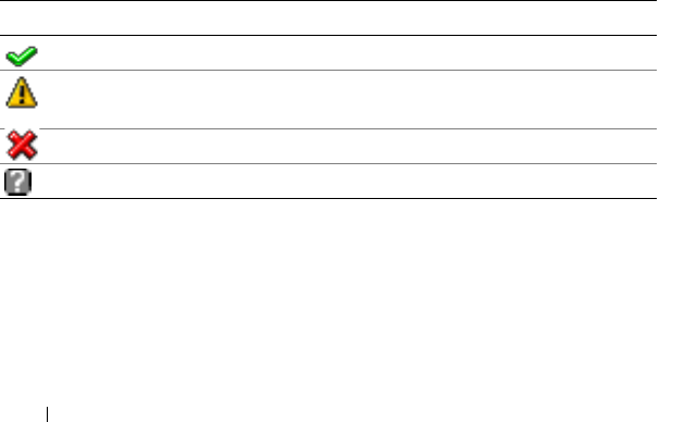
278 Recovering and Troubleshooting the Managed Server
Problem Solving Tools
This section describes iDRAC6 utilities you can use to diagnose problems
with your system, especially when you are trying to solve problems remotely.
• Checking the system health
• Checking the System Event Log for error messages
• Checking the POST codes
• Viewing the last crash screen
• Checking the Server Status Screen on the LCD for Error Messages
• Viewing the iDRAC6 log
• Accessing system information
• Identifying the managed server in the chassis
• Using the diagnostics console
• Managing power on a remote system
Checking the System Health
When you log in to the iDRAC6 Web interface, the first screen displayed
describes the health of the system components. Table 17-3 describes the
meaning of the system health indicators.
Click any component on the Health screen to see information about the
component. Sensor readings are displayed for batteries, temperatures,
voltages, and power monitoring, helping to diagnose some types of problems.
The iDRAC6 and CMC information screens provide useful current status and
configuration information.
Table 17-3. System Health Indicators
Indicator Description
A green check mark indicates a healthy (normal) status condition.
A yellow triangle containing an exclamation point indicates a warning
(noncritical) status condition.
A red X indicates a critical (failure) status condition.
A question mark icon indicates that the status is unknown.
Recovering and Troubleshooting the Managed Server 279
Checking the System Event Log (SEL)
The SEL Log screen displays messages for events that occur on the
managed server.
To view the System Event Log, perform the following steps:
1
Click
System
and then click the
Logs
tab.
2
Click
System Event Log
to display the
System Event Log
screen.
The
System Event Log
screen displays a system health indicator
(see Table 17-3), a time stamp, and a description of the event.
3
Click the appropriate
System Event Log
button to continue
(see Table 17-4).
Checking the Post Codes
The Post Codes screen displays the last system post code prior to booting the
operating system. Post codes are progress indicators from the system BIOS,
indicating various stages of the boot sequence from Power on Reset, and allow
you to diagnose any faults related to system boot-up.
NOTE: View the text for POST code message numbers in the LCD display or in the
Hardware Owner’s Manual.
Table 17-4. SEL Buttons
Button Action
Print Prints the SEL in the sort order that it appears in the window.
Clear Log Clears the SEL.
NOTE: The Clear Log button appears only if you have Clear Logs permission.
Save As Opens a pop-up window that enables you to save the SEL to a directory of
your choice.
NOTE: If you are using Internet Explorer and encounter a problem when
saving, be sure to download the Cumulative Security Update for Internet
Explorer, located on the Microsoft® Support website at
support.microsoft.com.
Refresh Reloads the SEL screen.

280 Recovering and Troubleshooting the Managed Server
To view the Post Codes, perform the following steps:
1
Click
System
, the
Logs
tab, and then
Post Codes
.
The
Post Codes
screen displays a system health indicator (see Table 17-3),
a hexadecimal code, and a description of the code.
2
Click the appropriate
Post Code
button to continue (see Table 17-5).
Viewing the Last System Crash Screen
NOTE: The last crash screen feature must be configured in the Server Administrator
and in the iDRAC6 Web interface. See "Configuring the Managed Server to Capture
the Last Crash Screen" for instructions on configuring this feature.
The Last Crash Screen screen displays the most recent crash screen, which
includes information about the events that occurred before the system crash.
The last system crash image is saved in the iDRAC6 persistent store and is
remotely accessible.
To view the Last Crash Screen screen, perform the following steps:
• Click
System
, the
Logs
tab, and then
Last Crash
.
The Last Crash Screen screen provides the buttons shown in Table 17-6:
NOTE: The Save and Delete buttons do not appear if there is no saved crash screen.
Table 17-5. Post Code Buttons
Button Action
Print Prints the Post Codes screen.
Refresh Reloads the Post Codes screen.

Recovering and Troubleshooting the Managed Server 281
NOTE: Due to fluctuations in the Auto Recovery timer, the Last Crash Screen may
not be captured when the System Reset Timer is configured with a value that is too
high. The default setting is 480 seconds. Use Server Administrator or IT Assistant to
set the System Reset Timer to 60 seconds and ensure that the Last Crash Screen
functions properly. See "Configuring the Managed Server to Capture the Last Crash
Screen" for additional information.
Viewing the Most Recent Boot Sequences
If you experience boot problems, you can view the screen activity of what
happened during the last three boot sequences from the Boot Capture
screen. Playback of the boot screens occurs at a rate of 1 frame per second.
Table 17-7 lists the control actions available.
NOTE: You must have administrator privileges to view playback of the Boot Capture
sequences.
Table 17-6. Last Crash Screen Buttons
Button Action
Print Prints the Last Crash Screen screen.
Save Opens a pop-up window that enables you to save the Last Crash Screen to a
directory of your choice.
Delete Deletes the Last Crash Screen screen.
Refresh Reloads the Last Crash Screen screen.
Table 17-7. Boot Capture Options
Button/Option Description
Select the boot
sequence
Allows you to select the boot sequence to load and play.
• Boot Capture 1 — Loads the most recent boot sequence.
• Boot Capture 2 — Loads the (second most recent) boot
sequence that occurred prior to Boot Capture 1.
• Boot Capture 3 — Loads the (third most recent) boot
sequence that occurred prior to Boot Capture 2.
Save As Creates a compressed .zip file that contains all boot capture
images of the current sequence. The user must have
administrator privileges to perform this action.

282 Recovering and Troubleshooting the Managed Server
Checking the Server Status Screen for Error Messages
When a flashing amber LED is lit, and a particular server has an error,
the main Server Status Screen on the LCD will highlight the affected server
in orange. Use the LCD navigation buttons to highlight the affected server,
then click the center button. Error and warning messages will be displayed on the
second line. The following table lists all of the error messages and their severity.
Previous Screen Takes you to previous screen, if any, in the replay console.
Play Starts the screenplay from current screen in the replay console.
Pause Pauses the screenplay on the current screen being displayed in
the replay console.
Stop Stops the screenplay and loads the first screen of that boot
sequence.
Next Screen Takes you to next screen, if any, in the replay console.
Print Prints the Boot Capture image that appears on the screen.
Refresh Reloads the Boot Capture screen.
Table 17-8. Server Status Screen
Severity Message Cause
Warning System Board Ambient Temp:
Temperature sensor for System
Board, warning event
Server ambient temperature
crossed a warning threshold
Critical System Board Ambient Temp:
Temperature sensor for System
Board, failure event
Server ambient temperature
crossed a failure threshold
Critical System Board CMOS Battery:
Battery sensor for System Board,
failed was asserted
CMOS battery is not present or
has no voltage
Warning System Board System Level:
Current sensor for System Board,
warning event
Current crossed a warning
threshold
Table 17-7. Boot Capture Options (continued)
Button/Option Description

Recovering and Troubleshooting the Managed Server 283
Critical System Board System Level:
Current sensor for System Board,
failure event
Current crossed a failure
threshold
Critical CPU<number> <voltage sensor
name>: Voltage sensor for
CPU<number>, state asserted
was asserted
Voltage out of range
Critical System Board <voltage sensor
name>: Voltage sensor for
System Board, state asserted was
asserted
Voltage out of range
Critical CPU<number> <voltage sensor
name>: Voltage sensor for
CPU<number>, state asserted
was asserted
Voltage out of range
Critical CPU<number> Status:
Processor sensor for
CPU<number, IERR was
asserted
CPU failure
Critical CPU<number> Status:
Processor sensor for
CPU<number>, thermal tripped
was asserted
CPU overheated
Critical CPU<number> Status:
Processor sensor for
CPU<number, configuration
error was asserted
Incorrect processor type or in
wrong location
Critical CPU<number> Status:
Processor sensor for
CPU<number>, presence was
deasserted
Required CPU is missing or
not present
Critical System Board Video Riser:
Module sensor for System Board,
device removed was asserted
Required module was removed
Table 17-8. Server Status Screen (continued)
Severity Message Cause

284 Recovering and Troubleshooting the Managed Server
Critical Mezz B<slot number> Status:
Add-in Card sensor for Mezz
B<slot number>, install error
was asserted
Incorrect Mezzanine card
installed for IO fabric
Critical Mezz C<slot number> Status:
Add-in Card sensor for Mezz
C<slot number>, install error
was asserted
Incorrect Mezzanine card
installed for I/O fabric
Critical Backplane Drive <number>:
Drive Slot sensor for Backplane,
drive removed
Storage drive was removed
Critical Backplane Drive <number>:
Drive Slot sensor for Backplane,
drive fault was asserted
Storage drive failed
Critical System Board PFault Fail Safe:
Voltage sensor for System Board,
state asserted was asserted
This event is generated when
the system board voltages are
not at normal levels
Critical System Board OS Watchdog:
Watchdog sensor for System
Board, timer expired was asserted
The iDRAC6 watchdog timer
expired and no action is set
Critical System Board OS Watchdog:
Watchdog sensor for System
Board, reboot was asserted
The iDRAC6 watchdog
detected that the system has
crashed (timer expired because
no response was received from
Host) and the action is set to
reboot
Critical System Board OS Watchdog:
Watchdog sensor for System
Board, power off was asserted
The iDRAC6 watchdog
detected that the system has
crashed (timer expired because
no response was received from
Host) and the action is set to
power off
Table 17-8. Server Status Screen (continued)
Severity Message Cause

Recovering and Troubleshooting the Managed Server 285
Critical System Board OS Watchdog:
Watchdog sensor for System
Board, power cycle was asserted
The iDRAC6 watchdog
detected that the system has
crashed (timer expired because
no response was received from
Host) and the action is set to
power cycle
Critical System Board SEL: Event Log
sensor for System Board, log full
was asserted
The SEL device detects that
only one entry can be added to
the SEL before it is full
Warning ECC Corr Err: Memory sensor,
correctable ECC
( <DIMM Location> ) was
asserted
Correctable ECC errors
reached a critical rate
Critical ECC Uncorr Err: Memory sensor,
uncorrectable ECC
( <DIMM Location> ) was
asserted
An uncorrectable ECC error
was detected
Critical I/O Channel Chk: Critical Event
sensor, I/O channel check NMI
was asserted
A critical interrupt is generated
in the I/O Channel
Critical PCI Parity Err: Critical Event
sensor, PCI PERR was asserted
Parity error was detected on the
PCI bus
Critical PCI System Err: Critical Event
sensor, PCI SERR
( <Slot number or PCI Device
ID>) was asserted
PCI error detected by device
Critical SBE Log Disabled: Event Log
sensor, correctable memory error
logging disabled was asserted
Single bit error logging is
disabled when too many SBE
get logged
Critical Logging Disabled: Event Log
sensor, all event logging disabled
was asserted
All error logging is disabled
Non-Recoverable CPU Protocol Err:
Processor sensor, transition to
non-recoverable was asserted
The processor protocol entered
a non-recoverable state
Table 17-8. Server Status Screen (continued)
Severity Message Cause

286 Recovering and Troubleshooting the Managed Server
Non-Recoverable CPU Bus PERR: Processor sensor,
transition to non-recoverable
was asserted
The processor bus PERR
entered a non-recoverable state
Non-Recoverable CPU Init Err: Processor sensor,
transition to non-recoverable
was asserted
The processor initialization
entered a non-recoverable state
Non-Recoverable CPU Machine Chk: Processor
sensor, transition to
non-recoverable was asserted
The processor machine check
entered a non-recoverable state
Critical Memory Spared: Memory sensor,
redundancy lost
( <DIMM Location> ) was
asserted
Memory spare is no longer
redundant
Critical Memory Mirrored: Memory
sensor, redundancy lost
( <DIMM Location> ) was
asserted
Mirrored memory is no longer
redundant
Critical Memory RAID: Memory sensor,
redundancy lost
( <DIMM Location> ) was
asserted
RAID Memory is no longer
redundant
Warning Memory Added: Memory sensor,
presence ( <DIMM Location> )
was deasserted
Added memory module was
removed
Warning Memory Removed: Memory
sensor, presence ( <DIMM
Location> ) was deasserted
Memory module was removed
Critical Memory Cfg Err: Memory sensor,
configuration error
( <DIMM Location> ) was
asserted
Memory configuration is
incorrect for the system
Warning Mem Redun Gain: Memory
sensor, redundancy degraded
( <DIMM Location> ) was
asserted
Memory redundancy is
downgraded but not lost
Table 17-8. Server Status Screen (continued)
Severity Message Cause

Recovering and Troubleshooting the Managed Server 287
Critical PCIE Fatal Err: Critical Event
sensor, bus fatal error was asserted
Fatal error is detected on the
PCIE bus
Critical Chipset Err: Critical Event
sensor, PCI PERR was asserted
Chip error is detected
Warning Mem ECC Warning: Memory
sensor, transition to non-critical
from OK (<DIMM Location> )
was asserted
Correctable ECC errors have
increased from a normal rate
Critical Mem ECC Warning: Memory
sensor, transition to critical from
less severe ( <DIMM Location> )
was asserted
Correctable ECC errors have
reached a critical rate
Critical POST Err: POST sensor,
No memory installed
No memory detected on board
Critical POST Err: POST sensor, Memory
configuration error
Memory detected but is not
configurable
Critical POST Err: POST sensor,
Unusable memory error
Memory configured but
not usable
Critical POST Err: POST sensor,
Shadow BIOS failed
System BIOS shadow failure
Critical POST Err: POST sensor,
CMOS failed
CMOS failure
Critical POST Err: POST sensor,
DMA controller failed
DMA controller failure
Critical POST Err: POST sensor,
Interrupt controller failed
Interrupt controller failure
Critical POST Err: POST sensor,
Timer refresh failed
Timer refresh failure
Critical POST Err: POST sensor,
Programmable interval
timer error
Programmable interval
timer error
Critical POST Err: POST sensor,
Parity error
Parity error
Table 17-8. Server Status Screen (continued)
Severity Message Cause

288 Recovering and Troubleshooting the Managed Server
Critical POST Err: POST sensor,
SIO failed
SIO failure
Critical POST Err: POST sensor,
Keyboard controller failed
Keyboard controller failure
Critical POST Err: POST sensor,
System management interrupt
initialization failed
System Management Interrupt
initialization failure
Critical POST Err: POST sensor,
BIOS shutdown test failed
BIOS shutdown test failure
Critical POST Err: POST sensor,
BIOS POST memory test failed
BIOS POST memory test
failure
Critical POST Err: POST sensor,
Dell remote access controller
configuration failed
Dell Remote Access Controller
configuration failure
Critical POST Err: POST sensor,
CPU configuration failed
CPU configuration failure
Critical POST Err: POST sensor,
Incorrect memory configuration
Incorrect memory
configuration
Critical POST Err: POST sensor,
POST failure
General failure after video
Critical Hdwar version err: Version
Change sensor, hardware
incompatibility was asserted
Incompatible hardware was
detected
Critical Hdwar version err: Version
Change sensor, hardware
incompatibility (BMC firmware)
was asserted
Hardware is incompatible with
the firmware
Critical Hdwar version err: Version
Change sensor, hardware
incompatibility (BMC firmware
and CPU mismatch) was asserted
CPU and firmware not
compatible
Table 17-8. Server Status Screen (continued)
Severity Message Cause

Recovering and Troubleshooting the Managed Server 289
Critical Mem Overtemp: Memory sensor,
correctable ECC <DIMM
Location> was asserted
Memory module overheating
Critical Mem Fatal SB CRC: Memory
sensor, uncorrectable ECC
was asserted
South bridge memory failed
Critical Mem Fatal NB CRC: Memory
sensor, uncorrectable ECC
was asserted
North bridge memory failed
Critical WatchDog Timer: Watchdog
sensor, reboot was asserted
Watch dog timer caused
system to reboot
Critical WatchDog Timer: Watchdog
sensor, timer expired was asserted
Watch dog timer expired but
no action taken
Warning Link Tuning: Version Change
sensor, successful software or
F/W change was deasserted
Failed to update link tuning
setting for proper NIC operation
Warning Link Tuning: Version Change
sensor, successful hardware
change <device slot number>
was deasserted
Failed to update link tuning
setting for proper NIC operation
Critical LinkT/FlexAddr: Link Tuning
sensor, failed to program virtual
MAC address (Bus # Device #
Function #) was asserted
Flex address could not be
programmed for this device
Critical LinkT/FlexAddr: Link Tuning
sensor, device option ROM failed
to support link tuning or flex
address (Mezz <location>)
was asserted
Option ROM does not support
Flex address or linking tuning
Critical LinkT/FlexAddr: Link Tuning
sensor, failed to get link tuning or
flex address data from BMC/
iDRAC6 was asserted
Failed to obtain linking tuning
or Flex address information
from BMC/iDRAC6
Table 17-8. Server Status Screen (continued)
Severity Message Cause

290 Recovering and Troubleshooting the Managed Server
Viewing the iDRAC6 Log
The iDRAC6 Log is a persistent log maintained in iDRAC6 firmware.
The log contains a list of user actions (such as log in, log out, and security
policy changes) and alerts issued by iDRAC6. The oldest entries are
overwritten when the log becomes full.
Where the System Event Log (SEL) contains records of events that occur in
the managed server, the iDRAC Log contains records of events that occur in
iDRAC6.
To access the iDRAC Log, perform the following steps:
• Click
System
→
Remote Access
→
iDRAC
and
then click
iDRAC Log
.
The iDRAC Log provides the information in Table 17-9.
Critical LinkT/FlexAddr: Link Tuning
sensor, device option ROM failed
to support link tuning or flex
address (Mezz XX) was asserted
This event is generated when
the PCI device Option ROM
for a NIC does not support
link tuning or the Flex
addressing feature
Critical LinkT/FlexAddr: Link Tuning
sensor, failed to program the
virtual MAC address
(<location>) was asserted
This event is generated when
the BIOS fails to program the
virtual MAC address on the
given NIC device
Critical I/O Fatal Err: Fatal IO Group
sensor, fatal IO error
(<location>)
This event is generated in
association with a CPU IERR
and indicates which device
caused the CPU IERR
Warning PCIE NonFatal Er: Non Fatal I/O
Group sensor, PCIe error
(<location>)
This event is generated in
association with a CPU IERR
Table 17-8. Server Status Screen (continued)
Severity Message Cause

Recovering and Troubleshooting the Managed Server 291
Using the iDRAC6 Log Buttons
The iDRAC Log screen provides the following buttons (see Table 17-10).
Viewing System Information
The System Summary screen displays information about the following system
components:
• Main system enclosure
• Integrated Dell Remote Access Controller
To access the system information, click System→ Properties.
Table 17-9. iDRAC6 Log Information
Field Description
Date/Time The date and time (for example, Dec 19 16:55:47).
iDRAC6 sets its clock from the managed server’s clock. When iDRAC6
initially starts and is unable to communicate with the managed server,
the time is displayed as the string System Boot.
Source The interface that caused the event.
Description A brief description of the event and the user name that logged in to
iDRAC6.
Table 17-10. iDRAC6 Log Buttons
Button Action
Print Prints the iDRAC Log screen.
Clear Log Clears the iDRAC Log entries.
NOTE: The Clear Log button only appears if you have Clear Logs
permission.
Save As Opens a pop-up window that enables you to save the iDRAC Log to a
directory of your choice.
NOTE: If you are using Internet Explorer and encounter a problem when
saving, be sure to download the Cumulative Security Update for Internet
Explorer, located on the Microsoft Support website at
support.microsoft.com.
Refresh Reloads the iDRAC Log screen.

292 Recovering and Troubleshooting the Managed Server
Main System Enclosure
Table 17-11 and Table 17-12 describe the main system enclosure properties.
Integrated Dell Remote Access Controller
Table 17-13 describes iDRAC6 properties.
Table 17-11. System Information Fields
Field Description
Description Provides a system description.
BIOS Version Lists the system BIOS version.
Service Tag Lists the system Service Tag number.
Host Name Provides the host system’s name.
OS Name Lists the operating system running on the system.
Table 17-12. Auto Recovery Fields
Field Description
Recovery Action When a system hang is detected, iDRAC6 can be configured to
perform one of the following actions: No Action, Hard Reset,
Power Down, or Power Cycle.
Initial Countdown The number of seconds after a system hang is detected at which
iDRAC6 will perform a Recovery Action.
Present Countdown The current value, in seconds, of the countdown timer.
Table 17-13. iDRAC6 Information Fields
Field Description
Date/Time Provides the current date and time on iDRAC6 in GMT.
Firmware Version Lists the version of iDRAC6 firmware.
Firmware Updated Lists the date the firmware was last updated. The date is
displayed in UTC format, for example: Tue, 8 May 2007,
22:18:21 UTC.

Recovering and Troubleshooting the Managed Server 293
Identifying the Managed Server in the Chassis
The PowerEdge M1000e chassis holds up to sixteen servers. To locate a
specific server in the chassis, you can use the iDRAC6 Web interface to turn
on a blue flashing LED on the server. When you turn on the LED, you can
specify the number of seconds that you want the LED to flash to ensure that
you can reach the chassis while the LED is still flashing. Entering 0 leaves the
LED flashing until you disable it.
To identify the server:
1
Click
System
→
Remote Access
→
iDRAC
→
Troubleshooting
.
2
On the
Identify
screen, check
Identify Server
.
3
In the
Identify Server Timeout
field, enter the number of seconds that you
want the LED to blink. Enter
0
if you want the LED to remain flashing
until you disable it.
4
Click
Apply.
A blue LED on the server will flash for the number of seconds you specified.
IP Address The 32-bit address that identifies the network interface.
The value is displayed in a dot separated format,
such as 143.166.154.127.
Gateway The IP Address of the gateway that acts as a bridge to
other networks. This value is in a dot separated format,
such as 143.166.150.5.
Subnet Mask The subnet mask identifies the parts of the IP Address that
make up the Extended Network Prefix and the Host Number.
The value is displayed in a dot separated format,
such as 255.255.0.0.
MAC Address The Media Access Control (MAC) Address that uniquely
identifies each NIC in a network, for example 00-00-0c-ac-08.
This is a Dell-assigned ID and cannot be edited.
DHCP Enabled Enabled indicates that the Dynamic Host Configuration
Protocol (DHCP) is enabled.
Disabled indicates that DHCP is not enabled.
Table 17-13. iDRAC6 Information Fields (continued)
Field Description

294 Recovering and Troubleshooting the Managed Server
If you entered 0 to leave the LED flashing, follow these steps to disable it:
1
Click
System
→
Remote Access
→
iDRAC
→
Troubleshooting
.
2
On the
Identify
screen, uncheck
Identify Server
.
3
Click
Apply.
Using the Diagnostics Console
iDRAC6 provides a standard set of network diagnostic tools (see Table 17-14)
that are similar to the tools included with Microsoft® Windows® or
Linux-based systems. Using the iDRAC6 Web interface, you can access the
network debugging tools.
To access the Diagnostics Console screen, perform the following steps:
1
Click
System
→
iDRAC
→
Troubleshooting
.
2
Click the
Diagnostics
tab.
Table 17-14 describes the commands that can be entered on the Diagnostics
Console screen. Enter a command and click Submit. The debugging results
appear in the Diagnostics Console screen.
Click the Clear button to clear the results displayed by the previous
command.
To refresh the Diagnostics Console screen, click Refresh.
Table 17-14. Diagnostic Commands
Command Description
arp Displays the contents of the Address Resolution Protocol (ARP)
table. ARP entries may not be added or deleted.
ifconfig Displays the contents of the network interface table.
netstat Prints the content of the routing table.
ping
<IP Address>
Verifies that the destination IP address is reachable from iDRAC6
with the current routing-table contents. A destination IP address
must be entered in the field to the right of this option. An Internet
control message protocol (ICMP) echo packet is sent to the
destination IP address based on the current routing-table contents.
gettracelog Displays the iDRAC6 trace log. See "gettracelog" for more
information.

Recovering and Troubleshooting the Managed Server 295
Managing Power on a Remote System
iDRAC6 enables you to remotely perform several power management actions
on the managed server. Use the Power Management screen to perform an
orderly shutdown through the operating system when rebooting and powering
on and off.
NOTE: You must have Execute Server Action Commands permission to perform
power management actions. See "Adding and Configuring iDRAC6 Users" for help
configuring user permissions.
1
Click
System
, then click the
Power Management
tab.
2
Select a
Power Control Action
, for example
Reset System (warm boot)
.
Table 17-15 provides information about Power Control Actions.
3
Click
Apply
to perform the selected action.
4
Click the appropriate button to continue. See Table 17-15.
Table 17-15. Power Control Actions
Power On
System
Turns on the system power (equivalent to pressing the power button
when the system power is off).
Powers Off
System
Turns off the system power (equivalent to pressing the power button
when the system power is on).
NMI
(Non-Masking
Interrupt)
Sends a high-level interrupt to the operating system, which causes
the system to halt operation to allow for critical diagnostic or
troubleshooting activities.
Graceful
Shutdown
Attempts to cleanly shut down the operating system, then powers off
the system. It requires an ACPI (Advanced Configuration and Power
Interface) aware operating system, which allows for system directed
power management.
NOTE: A graceful shutdown of the server operating system may not be
possible when the server software stops responding, or if you are not
logged as an administrator at a local Windows console. In these cases,
you must specify a forced reboot instead of a graceful shutdown of
Windows. In addition, depending on the version of the Windows OS,
there might be a policy configured around the shutdown process that
modifies shutdown behavior when triggered from iDRAC6. See
Microsoft’s documentation for the local computer policy “Shutdown:
Allow system to be shut down without having to login.”

296 Recovering and Troubleshooting the Managed Server
Troubleshooting and Frequently Asked Questions
Table 17-17 contains frequently asked questions about troubleshooting
issues.
Reset System
(warm boot)
Reboots the system without powering off (warm boot).
Power Cycle
System
Powers off, then reboots the system (cold boot).
Table 17-16. Power Management Buttons
Button Action
Print Prints the Power Management values that appear on the screen.
Refresh Reloads the Power Management screen.
Apply Saves any new settings that you make while viewing the Power
Management screen.
Table 17-17. Frequently Asked Questions/Troubleshooting
Question Answer
The LED on the
server is blinking
amber.
Check the SEL for messages and then clear the SEL to stop the
blinking LED.
From the iDRAC6 Web interface:
• See "Checking the System Event Log (SEL)"
From SM-CLP:
• See "SEL Management"
From the iDRAC6 Configuration Utility:
• See "System Event Log Menu"
There is a
blinking blue
LED on the
server.
A user has activated the locator ID for the server. This is a signal
to help them identify the server in the chassis. See "Identifying
the Managed Server in the Chassis" for information about
this feature.
Table 17-15. Power Control Actions (continued)

Recovering and Troubleshooting the Managed Server 297
How can I find
the IP address of
iDRAC6?
From the CMC Web interface:
1
Click
Chassis
→
Servers
, then click the
Setup
tab.
2
Click
Deploy
.
3
Read the IP address for your server from the table that is
displayed.
From the iKVM:
• Reboot the server and enter the iDRAC6 Configuration Utility
by pressing <Ctrl><E>.
OR
• Watch for the IP address to display during BIOS POST.
OR
• Select the "Dell CMC" console in the OSCAR to log in to the
CMC through a local serial connection.
CMC RACADM commands can be issued from this connection.
Refer to the CM
C Firmware User Guide
for a complete list of the
CMC RACADM subcommands.
You can also use the local RACADM getsysinfo command to view
the iDRAC6 IP address.
For example:
$ racadm getniccfg -m server-1
DHCP Enabled = 1
IP Address = 192.168.0.1
Subnet Mask = 255.255.255.0
Gateway = 192.168.0.1
From local RACADM:
1
Enter the following command at a command prompt:
racadm getsysinfo
From the LCD:
1
On the Main Menu, highlight
Server
and press the check button.
2
Select the server whose IP address you seek and press the
check button.
Table 17-17. Frequently Asked Questions/Troubleshooting (continued)
Question Answer

298 Recovering and Troubleshooting the Managed Server
How can I find
the IP address of
the CMC?
From the iDRAC6 Web interface:
• Click
System
→
Remote Access
→
CMC
.
The CMC IP address is displayed on the
Summary
screen.
OR
• Select the "Dell CMC" console in the OSCAR to log in to the
CMC through a local serial connection. CMC RACADM
commands can be issued from this connection. Refer to the
CM
C Firmware User Guide
for a complete list of the CMC
RACADM subcommands.
$ racadm getniccfg -m chassis
NIC Enabled = 1
DHCP Enabled = 1
Static IP Address = 192.168.0.120
Static Subnet Mask = 255.255.255.0
Static Gateway = 192.168.0.1
Current IP Address = 10.35.155.151
Current Subnet Mask = 255.255.255.0
Current Gateway = 10.35.155.1
Speed = Autonegotiate
Duplex = Autonegotiate
The iDRAC6
network
connection is
not working.
• Ensure the LAN cable is connected to the CMC.
• Ensure the iDRAC6 LAN is enabled.
I inserted the
server into the
chassis and
pressed the
power button,
but nothing
happened.
• iDRAC6 requires about 30 seconds to initialize before the server
can power up. Wait for 30 seconds and then press the power
button again.
• Check the CMC power budget. The chassis power budget may
be exceeded.
Table 17-17. Frequently Asked Questions/Troubleshooting (continued)
Question Answer

Recovering and Troubleshooting the Managed Server 299
I have forgotten
the iDRAC6
administrative
user name and
password.
You must restore iDRAC6 to its default settings.
1
Reboot the server and press <Ctrl><E> when prompted to
enter the iDRAC6 Configuration Utility.
2
On the
Configuration Utility
menu, highlight
Reset to Default
and press <Enter>.
For more information, see "Reset to Default."
How can I change
the name of the
slot for my server?
1
Log in to the CMC Web interface.
2
Open the
Chassis
tree and click
Servers
.
3
Click the
Setup
tab.
4
Enter the new name for the slot in the row for your server.
5
Click
Apply
.
When starting a
console
redirection
session from the
iDRAC6 Web
interface,
an ActiveX
security popup
appears.
iDRAC6 may not be a trusted site from the client browser.
To prevent the security popup from appearing every time you
begin a console redirection session, add iDRAC6 to the trusted
site list:
1
Click
Tools
→
Internet Options…
→
Security
→
Trusted sites
.
2
Click
Sites
and enter the IP address or the DNS name of iDRAC6.
3
Click
Add
.
When I start a
console
redirection
session, the
viewer screen is
blank.
If you have Virtual Media privilege but not Console Redirection
privilege, you are able to start the viewer so that you can access
the virtual media feature, but the managed server’s console
will not display.
Table 17-17. Frequently Asked Questions/Troubleshooting (continued)
Question Answer

300 Recovering and Troubleshooting the Managed Server
iDRAC6 does not
boot.
Remove and reinsert the server.
Check the CMC Web interface to see if iDRAC6 appears as an
upgradable component. If it does, follow the instructions in
"Updating iDRAC6 Firmware Using the CMC."
If this does not correct the problem, contact Technical Support.
When attempting
to boot the
managed server,
the power
indicator is green,
but there is no
POST or no video
at all.
This can happen if any of the following conditions is true:
• Memory is not installed or is inaccessible.
• The CPU is not installed or is inaccessible.
• The video riser card is missing or improperly connected.
Also, look for error messages in the iDRAC6 log from the iDRAC6
Web interface or from the LCD.
Table 17-17. Frequently Asked Questions/Troubleshooting (continued)
Question Answer

RACADM Subcommand Overview 301
RACADM Subcommand Overview
This section provides descriptions of the subcommands that are available in
the RACADM command line interface.
help
Table A-1 describes the help command.
Synopsis
racadm help
racadm help <
subcommand
>
Description
The help subcommand lists all of the subcommands that are available when
using the racadm command along with a one-line description. You may also
enter a subcommand after help to get the syntax for a specific subcommand.
Output
The racadm help command displays a complete list of subcommands.
The racadm help <subcommand> command displays information for the
specified subcommand only.
Supported Interfaces
•Local RACADM
Table A-1. Help Command
Command Definition
help Lists all of the subcommands available to use with
racadm and provides a short description for each.

302 RACADM Subcommand Overview
config
Table A-2 describes the config and getconfig subcommands.
Synopsis
racadm config [-c|-p] -f <
filename
>
racadm config -g <
groupName
> -o <
objectName
> [-i
<
index
>] <
value
>
Supported Interfaces
• Local RACADM
Description
The config subcommand allows you to set iDRAC6 configuration parameters
individually or to batch them as part of a configuration file. If the data is
different, that iDRAC6 object is written with the new value.
Input
Table A-3 describes the config subcommand options.
Table A-2. config/getconfig
Subcommand Definition
config Configures iDRAC6.
getconfig Gets iDRAC6 configuration data.
Table A-3. config Subcommand Options and Descriptions
Option Description
-f The -f <filename> option causes config to read the contents of the file
specified by <filename> and configure iDRAC6. The file must contain data
in the format specified in "Configuration File Syntax" on page 237.
-p The -p, or password, option directs config to delete the password entries
contained in the config file -f <filename> after the configuration is complete.
-g The -g <groupName>, or group, option must be used with the -o option.
The <groupName> specifies the group containing the object that is to be set.

RACADM Subcommand Overview 303
Output
This subcommand generates error output upon encountering either of the
following:
• Invalid syntax, group name, object name, index, or other invalid
database members
• RACADM CLI failures
This subcommand returns an indication of how many configuration objects
that were written out of how many total objects were in the .cfg file.
Examples
•
racadm config -g cfgLanNetworking -o
cfgNicIpAddress 10.35.10.110
Sets the
cfgNicIpAddress
configuration parameter (object) to the value
10.35.10.110. This IP address object is contained in the group
cfgLanNetworking
.
•
racadm config -f myrac.cfg
Configures or reconfigures iDRAC6. The
myrac.cfg
file may be created
with the
getconfig
command. The
myrac.cfg
file may also be edited
manually as long as the parsing rules are followed.
NOTE: The myrac.cfg file does not contain passwords. To include passwords
in the file, you must enter them manually. If you want to remove passwords
from the myrac.cfg file during configuration, use the -p option.
-o The -o <objectName> <value>, or object, option must be used with the -g
option. This option specifies the object name that is written with the
string <value>.
-i The -i <index>, or index, option is only valid for indexed groups and can be
used to specify a unique group. The index is specified here by the index
value, not a "named" value.
-c The -c, or check, option is used with the config subcommand and allows you
to parse the .cfg file to find syntax errors. If errors are found, the line number
and a short description of what is incorrect are displayed. Writes do not occur
to iDRAC6. This option is a check only.
Table A-3. config Subcommand Options and Descriptions (continued)
Option Description

304 RACADM Subcommand Overview
getconfig
The getconfig subcommand allows you to retrieve iDRAC6 configuration
parameters individually, or all the iDRAC6 configuration groups may
be retrieved and saved into a file.
Input
Table A-4 describes the getconfig subcommand options.
NOTE: The -f option without a file specification will output the contents of the file to
the terminal screen.
Table A-4. getconfig Subcommand Options
Option Description
-f The -f <filename> option directs getconfig to write the entire iDRAC6
configuration to a configuration file. This file can then be used for batch
configuration operations using the config subcommand.
NOTE: The -f option does not create entries for the cfgIpmiPet and
cfgIpmiPef groups. You must set at least one trap destination to capture the
cfgIpmiPet group to the file.
-g The -g <groupName>, or group, option can be used to display the
configuration for a single group. The groupName is the name for the group
used in the racadm.cfg files. If the group is an indexed group, use the -i option.
-h The -h, or help, option displays a list of all available configuration groups
that you can use. This option is useful when you do not remember exact
group names.
-i The -i <index>, or index, option is valid only for indexed groups and can
be used to specify a unique group. If -i <index> is not specified, a value of
1 is assumed for groups, which are tables that have multiple entries. The
index is specified by the index value, not a "named" value.
-o The -o <objectname>, or object, option specifies the object name that is
used in the query. This option can be used with the -g option.
-u The -u <username>, or user name, option can be used to display the
configuration for the specified user. The <username> option is the login
name for the user.
-v The -v, or verbose, option displays additional details with the display of the
properties and is used with the -g option.

RACADM Subcommand Overview 305
Output
This subcommand generates error output upon encountering either of the
following:
• Invalid syntax, group name, object name, index, or other invalid database
members
• RACADM CLI transport failures
If errors are not encountered, this subcommand displays the contents of the
specified configuration.
Examples
•
racadm getconfig -g cfgLanNetworking
Displays all of the configuration properties (objects) that are contained in
the group
cfgLanNetworking
.
•
racadm getconfig -f myrac.cfg
Saves all group configuration objects from iDRAC6 to
myrac.cfg
.
•
racadm getconfig -h
Displays a list of the available configuration groups on iDRAC6.
•racadm getconfig -u root
Displays the configuration properties for the user named
root
.
•
racadm getconfig -g cfgUserAdmin -i 2 -v
Displays the user group instance at index 2 with extensive information for
the property values.
Synopsis
racadm getconfig -f <
filename
>
racadm getconfig -g <
groupName
> [-i <
index
>]
racadm getconfig -u <
username
>
racadm getconfig -h
Supported Interfaces
•Local RACADM

306 RACADM Subcommand Overview
getssninfo
Table A-5 describes the getssninfo subcommand.
Synopsis
racadm getssninfo [-A] [-u <
username
> | *]
Description
The getssninfo command returns a list of users that are connected to
iDRAC6. The summary information provides the following information:
•Username
• IP address (if applicable)
• Session type (for example, SSH or telnet)
• Consoles in use (for example, Virtual Media or Virtual KVM)
Supported Interfaces
• Local RACADM
Input
Table A-6 describes the getssninfo subcommand options.
Table A-5. getssninfo Subcommand
Subcommand Definition
getssninfo Retrieves session information for one or more
currently active or pending sessions from the Session
Manager's session table.
Table A-6. getssninfo Subcommand Options
Option Description
-A The -A option eliminates the printing of data headers.
-u The -u <username> user name option limits the printed output to only the
detail session records for the given user name. If an asterisk (*) symbol is
given as the user name, all users are listed. Summary information is not
printed when this option is specified.

RACADM Subcommand Overview 307
Examples
•racadm getssninfo
Table A-7 provides an example of output from the racadm getssninfo
command.
•racadm getssninfo -A
"root" 143.166.174.19 "Telnet" "NONE"
•racadm getssninfo -A -u *
"root" "143.166.174.19" "Telnet" "NONE"
• "bob" "143.166.174.19" "GUI" "NONE"
getsysinfo
Table A-8 describes the racadm getsysinfo subcommand.
Synopsis
racadm getsysinfo [-d] [-s] [-w] [-A]
Description
The getsysinfo subcommand displays information related to iDRAC6, the
managed server, and the watchdog configuration.
Supported Interfaces
•Local RACADM
Table A-7. getssninfo Subcommand Output Example
User IP Address Type Consoles
root 192.168.0.10 Telnet Virtual KVM
Table A-8. getsysinfo
Command Definition
getsysinfo Displays iDRAC6 information, system information,
and watchdog status information.

308 RACADM Subcommand Overview
Input
Table A-9 describes the getsysinfo subcommand options.
Output
The getsysinfo subcommand displays information related to iDRAC6, the
managed server, and the watchdog configuration.
Sample Output
RAC Information:
RAC Date/Time = Wed Aug 22 20:01:33 2007
Firmware Version = 0.32
Firmware Build = 13661
Last Firmware Update = Mon Aug 20 08:09:36 2007
Hardware Version = NA
Current IP Address = 192.168.0.120
Current IP Gateway = 192.168.0.1
Current IP Netmask = 255.255.255.0
DHCP Enabled = 1
MAC Address = 00:14:22:18:cd:f9
Current DNS Server 1 = 10.32.60.4
Current DNS Server 2 = 10.32.60.5
DNS Servers from DHCP = 1
Register DNS RAC Name = 1
DNS RAC Name = iDRAC-783932693338
Current DNS Domain = us.dell.com
Table A-9. getsysinfo Subcommand Options
Option Description
-d Displays iDRAC6 information.
-s Displays system information
-w Displays watchdog information
-A Eliminates the printing of headers/labels.

RACADM Subcommand Overview 309
System Information:
System Model = PowerEdge M600
System BIOS Version = 0.2.1
BMC Firmware Version = 0.32
Service Tag = 48192
Host Name = dell-x92i38xc2n
OS Name =
Power Status = OFF
Watchdog Information:
Recovery Action = None
Present countdown value = 0 seconds
Initial countdown value = 0 seconds
Examples
•racadm getsysinfo -A -s
"System Information:" "PowerEdge M600" "0.2.1"
"0.32" "48192" "dell-x92i38xc2n" "" "ON"
•racadm getsysinfo -w -s
System Information:
System Model = PowerEdge M600
System BIOS Version = 0.2.1
BMC Firmware Version = 0.32
Service Tag = 48192
Host Name = dell-x92i38xc2n
OS Name =
Power Status = ON
Watchdog Information:
Recovery Action = None
Present countdown value = 0 seconds
Initial countdown value = 0 seconds

310 RACADM Subcommand Overview
Restrictions
The Hostname and OS Name fields in the getsysinfo output display accurate
information only if Dell OpenManage is installed on the managed server. If
OpenManage is not installed on the managed server, these fields may be
blank or inaccurate.
getractime
Table A-10 describes the getractime subcommand.
Synopsis
racadm getractime [-d]
Description
With no options, the getractime subcommand displays the time in a
common readable format.
With the -d option, getractime displays the time in the format,
yyyymmddhhmmss.mmmmmms
, which is the same format returned by the
UNIX® date command.
Output
The getractime subcommand displays the output on one line.
Sample Output
racadm getractime
Thu Dec 8 20:15:26 2005
racadm getractime -d
20071208201542.000000
Table A-10. getractime
Subcommand Definition
getractime Displays the current time from the remote access
controller.

RACADM Subcommand Overview 311
Supported Interfaces
•Local RACADM
setniccfg
Table A-11 describes the setniccfg subcommand.
Synopsis
racadm setniccfg -d
racadm setniccfg -s [<
ipAddress
> <
netmask
> <
gateway
>]
racadm setniccfg -o [<
ipAddress
> <
netmask
> <
gateway
>]
Description
The setniccfg subcommand sets the iDRAC6 IP address.
• The
-d
option enables DHCP for the NIC (default is DHCP enabled).
• The
-s
option enables static IP settings. The IP address, netmask, and
gateway can be specified. Otherwise, the existing static settings are used.
<
ipAddress
>, <
netmask
>, and <
gateway
> must be entered as dot-
separated strings.
racadm setniccfg -s 192.168.0.120 255.255.255.0
192.168.0.1
• The
-o
option disables the NIC completely.
<
ipAddress
>
,
<
netmask
>
,
and
<
gateway
>
must be entered as dot-separated strings.
racadm setniccfg -o 192.168.0.120 255.255.255.0
192.168.0.1
Output
The setniccfg subcommand displays an appropriate error message if the
operation is not successful. If successful, a message is displayed.
Table A-11. setniccfg
Subcommand Definition
setniccfg Sets the IP configuration for the controller.

312 RACADM Subcommand Overview
Supported Interfaces
• Local RACADM
getniccfg
Table A-12 describes the getniccfg subcommand.
Synopsis
racadm getniccfg
Description
The getniccfg subcommand displays the current NIC settings.
Sample Output
The getniccfg subcommand will display an appropriate error message if the
operation is not successful. Otherwise, on success, the output is displayed in
the following format:
NIC Enabled = 1
DHCP Enabled = 1
IP Address = 192.168.0.1
Subnet Mask = 255.255.255.0
Gateway = 192.168.0.1
Supported Interfaces
• Local RACADM
Table A-12. getniccfg
Subcommand Definition
getniccfg Displays the current IP configuration for iDRAC6.

RACADM Subcommand Overview 313
getsvctag
Table A-13 describes the getsvctag subcommand.
Synopsis
racadm getsvctag
Description
The getsvctag subcommand displays the service tag of the host system.
Example
Enter getsvctag at the command prompt. The output is displayed as follows:
Y76TP0G
The command returns 0 on success and nonzero on errors.
Supported Interfaces
•Local RACADM
racreset
Table A-14 describes the racreset subcommand.
NOTE: When you issue a racreset subcommand, iDRAC6 may require up to one
minute to return to a usable state.
Synopsis
racadm racreset
Table A-13. getsvctag
Subcommand Definition
getsvctag Displays a service tag.
Table A-14. racreset
Subcommand Definition
racreset Resets iDRAC6.

314 RACADM Subcommand Overview
Description
The racreset subcommand issues a reset to iDRAC6. The reset event is
written into the iDRAC6 log.
Examples
•racadm racreset
Start the iDRAC6 soft-reset sequence.
Supported Interfaces
• Local RACADM
racresetcfg
Table A-15 describes the racresetcfg subcommand.
Synopsis
racadm racresetcfg
Supported Interfaces
• Local RACADM
Description
The racresetcfg command removes all user-configured database property
entries. The database has default properties for all entries that are used to
restore iDRAC6 back to the default settings.
NOTE: This command deletes your current iDRAC6 configuration and resets
iDRAC6 configuration to the default settings. After reset, the default name and
password are root and calvin, respectively, and the IP address is 192.168.0.120 plus
the number of the slot the server inhabits in the chassis.
Table A-15. racresetcfg
Subcommand Definition
racresetcfg Resets the entire RAC configuration to factory default values.

RACADM Subcommand Overview 315
serveraction
Table A-16 describes the serveraction subcommand.
Synopsis
racadm serveraction <
action
>
Description
The serveraction subcommand enables users to perform power management
operations on the host system. Table A-17 describes the serveraction power
control options.
Output
The serveraction subcommand displays an error message if the requested
operation could not be performed, or a success message if the operation
completed successfully.
Table A-16. serveraction
Subcommand Definition
serveraction Executes a managed server reset or power-on/off/cycle.
Table A-17. serveraction Subcommand Options
String Definition
<action>Specifies the action. The <action> string options are:
•
powerdown
— Powers down the managed server.
•
powerup
— Powers up the managed server.
•
powercycle
— Issues a power-cycle operation on the managed server.
This action is similar to pressing the power button on the system’s
front panel to power down and then power up the system.
•
powerstatus
— Displays the current power status of the server (
ON
,
or
OFF
).
•
hardreset
— Performs a reset (reboot) operation on the managed server.
316 RACADM Subcommand Overview
Supported Interfaces
• Local RACADM
getraclog
Table A-18 describes the racadm getraclog command.
Synopsis
racadm getraclog -i
racadm getraclog [-A] [-o] [-c
count
] [-s
start-
record
] [-m]
Description
The getraclog -i command displays the number of entries in the iDRAC6 log.
NOTE: If no options are provided, the entire log is displayed.
The following options allow the getraclog command to read entries:
Table A-18. getraclog
Command Definition
getraclog -i Displays the number of entries in the iDRAC6 log.
getraclog Displays the iDRAC6 log entries.
Table A-19. getraclog Subcommand Options
Option Description
-A Displays the output with no headers or labels.
-c Provides the maximum count of entries to be returned.
-m Displays one screen of information at a time and prompts the user to
continue (similar to the UNIX more command).
-o Displays the output in a single line.
-s Specifies the starting record used for the display.

RACADM Subcommand Overview 317
Output
The default output display shows the record number, time stamp, source, and
description. The timestamp begins at midnight, January 1 and increases until
the managed server boots. After the managed server boots, the managed
server’s system time is used for the timestamp.
Sample Output
Record: 1
Date/Time: Dec 8 08:10:11
Source: login[433]
Description: root login from 143.166.157.103
Supported Interfaces
•Local RACADM
clrraclog
Synopsis
racadm clrraclog
Description
The clrraclog subcommand removes all existing records from the iDRAC6
log. A new single record is created to record the date and time when the
log was cleared.
getsel
Table A-20 describes the getsel command.
Table A-20. getsel
Command Definition
getsel -i Displays the number of entries in the System
Event Log.
getsel Displays SEL entries.

318 RACADM Subcommand Overview
Synopsis
racadm getsel -i
racadm getsel [-E] [-R] [-A] [-o] [-c
count
] [-s
count
] [-m]
Description
The getsel -i command displays the number of entries in the SEL.
The following getsel options (without the -i option) are used to read entries.
NOTE: If no arguments are specified, the entire log is displayed.
Output
The default output display shows the record number, timestamp, severity, and
description.
For example:
Record: 1
Date/Time: 11/16/2005 22:40:43
Severity: Ok
Description: System Board SEL: event log sensor for
System Board, log cleared was asserted
Table A-21. getsel Subcommand Options
Option Description
-A Specifies output with no display headers or labels.
-c Provides the maximum count of entries to be returned.
-o Displays the output in a single line.
-s Specifies the starting record used for the display.
-E Places the 16 bytes of raw SEL at the end of each line of output as a
sequence of hex values.
-R Only the raw data is printed.
-m Displays one screen at a time and prompts the user to continue (similar to
the UNIX more command).
RACADM Subcommand Overview 319
Supported Interfaces
•Local RACADM
clrsel
Synopsis
racadm clrsel
Description
The clrsel command removes all existing records from the System Event Log
(SEL).
Supported Interfaces
•Local RACADM
gettracelog
Table A-22 describes the gettracelog subcommand.
Synopsis
racadm gettracelog -i
racadm gettracelog [-A] [-o] [-c count] [-s
startrecord] [-m]
Table A-22. gettracelog
Command Definition
gettracelog -i Displays the number of entries in the iDRAC trace
log.
gettracelog Displays the iDRAC trace log.

320 RACADM Subcommand Overview
Description
The gettracelog (without the -i option) command reads entries.
The following gettracelog entries are used to read entries:
Output
The default output display shows the record number, timestamp, source, and
description. The timestamp begins at midnight, January 1 and increases until
the managed system boots. After the managed system boots, the managed
system’s system time is used for the timestamp.
For example:
Record: 1
Date/Time: Dec 8 08:21:30
Source: ssnmgrd[175]
Description: root from 143.166.157.103: session
timeout sid 0be0aef4
Supported Interfaces
• Local RACADM
Table A-23. gettracelog Subcommand options
Option Description
-i Displays the number of entries in the iDRAC trace log.
-m Displays one screen at a time and prompts the user to continue
(similar to the UNIX more command).
-o Displays the output in a single line.
-c specifies the number of records to display.
-s specifies the starting record to display.
-A do not display headers or labels.

RACADM Subcommand Overview 321
sslcsrgen
Table A-24 describes the sslcsrgen subcommand.
Synopsis
racadm sslcsrgen [-g] [-f <
filename
>]
racadm sslcsrgen -s
Description
The sslcsrgen subcommand can be used to generate a CSR and download the
file to the client’s local file system. The CSR can be used for creating a
custom SSL certificate that can be used for SSL transactions on the RAC.
Options
Table A-25 describes the sslcsrgen subcommand options.
NOTE: If the -f option is not specified, the filename defaults to sslcsr in your current
directory.
If no options are specified, a CSR is generated and downloaded to the local
file system as sslcsr by default. The -g option cannot be used with the -s
option, and the -f option can only be used with the -g option.
Table A-24. sslcsrgen
Subcommand Description
sslcsrgen Generates and downloads an SSL certificate signing
request (CSR) from the RAC.
Table A-25. sslcsrgen Subcommand Options
Option Description
-g Generates a new CSR.
-s Returns the status of a CSR generation process (generation in progress,
active, or none).
-f Specifies the filename of the location, <filename>, where the CSR will
be downloaded.

322 RACADM Subcommand Overview
The sslcsrgen -s subcommand returns one of the following status codes:
• CSR was generated successfully.
• CSR does not exist.
• CSR generation in progress.
NOTE: Before a CSR can be generated, the CSR fields must be configured in the
RACADM cfgRacSecurity group. For example: racadm config -g
cfgRacSecurity -o cfgRacSecCsrCommonName MyCompany
Examples
racadm sslcsrgen -s
or
racadm sslcsrgen -g -f c:\csr\csrtest.txt
Supported Interfaces
• Local RACADM
sslcertupload
Table A-26 describes the sslcertupload subcommand.
Synopsis
racadm sslcertupload -t <
type
> [-f <
filename
>]
Table A-26. sslcertupload
Subcommand Description
sslcertupload Uploads a custom SSL server or CA certificate from
the client to iDRAC6.

RACADM Subcommand Overview 323
Options
Table A-27 describes the sslcertupload subcommand options.
The sslcertupload command returns 0 when successful and returns a nonzero
number when unsuccessful.
Example
racadm sslcertupload -t 1 -f c:\cert\cert.txt
Supported Interfaces
•Local RACADM
sslcertdownload
Table A-28 describes the sslcertdownload subcommand.
Synopsis
racadm sslcertdownload -t <
type
> [-f <
filename
>]
Table A-27. sslcertupload Subcommand Options
Option Description
-t Specifies the type of certificate to upload, either the CA certificate or
server certificate.
1 = server certificate
2 = CA certificate
-f Specifies the file name of the certificate to be uploaded. If the file is not
specified, the sslcert file in the current directory is selected.
Table A-28. sslcertdownload
Subcommand Description
sslcertdownload Downloads an SSL certificate from the RAC to the
client’s file system.

324 RACADM Subcommand Overview
Options
Table A-29 describes the sslcertdownload subcommand options.
The sslcertdownload command returns 0 when successful and returns a
nonzero number when unsuccessful.
Example
racadm sslcertdownload -t 1 -f c:\cert\cert.txt
Supported Interfaces
• Local RACADM
sslcertview
Table A-30 describes the sslcertview subcommand.
Synopsis
racadm sslcertview -t <
type
> [-A]
Table A-29. sslcertdownload Subcommand Options
Option Description
-t Specifies the type of certificate to download, either the Microsoft®
Active Directory® certificate or server certificate.
1 = server certificate
2 = Microsoft Active Directory certificate
-f Specifies the file name of the certificate to be downloaded. If the -f
option or the filename is not specified, the sslcert file in the current
directory is selected.
Table A-30. sslcertview
Subcommand Description
sslcertview Displays the SSL server or CA certificate that exists
on iDRAC6.

RACADM Subcommand Overview 325
Options
Table A-31 describes the sslcertview subcommand options.
Output Example
racadm sslcertview -t 1
Serial Number : 00
Subject Information:
Country Code (CC) : US
State (S) : Texas
Locality (L) : Round Rock
Organization (O) : Dell Inc.
Organizational Unit (OU) : Remote Access Group
Common Name (CN) : iDRAC default certificate
Issuer Information:
Country Code (CC) : US
State (S) : Texas
Locality (L) : Round Rock
Organization (O) : Dell Inc.
Organizational Unit (OU) : Remote Access Group
Common Name (CN) : iDRAC default certificate
Table A-31. sslcertview Subcommand Options
Option Description
-t Specifies the type of certificate to view, either the Microsoft Active
Directory certificate or server certificate.
1 = server certificate
2 = Microsoft Active Directory certificate
-A Prevents printing headers/labels.

326 RACADM Subcommand Overview
Valid From : Jul 8 16:21:56 2005 GMT
Valid To : Jul 7 16:21:56 2010 GMT
racadm sslcertview -t 1 -A
00
US
Texas
Round Rock
Dell Inc.
Remote Access Group
iDRAC default certificate
US
Texas
Round Rock
Dell Inc.
Remote Access Group
iDRAC default certificate
Jul 8 16:21:56 2005 GMT
Jul 7 16:21:56 2010 GMT
Supported Interfaces
• Local RACADM
testemail
Table A-32 describes the testemail subcommand.
Synopsis
racadm testemail -i <
index
>
Table A-32. testemail configuration
Subcommand Description
testemail Tests the iDRAC6 e-mail alerting feature.

RACADM Subcommand Overview 327
Description
Sends a test e-mail from iDRAC6 to a specified destination.
Prior to executing the testemail command, ensure that the specified index in
the RACADM cfgEmailAlert group is enabled and configured properly.
Table A-33 provides an example of commands for the cfgEmailAlert group.
Options
Table A-34 describes the testemail subcommand options.
Output
None.
Table A-33. testemail Configuration
Action Command
Enable the alert racadm config -g cfgEmailAlert -o
cfgEmailAlertEnable
-i 1 1
Set the destination
e-mail address
racadm config -g cfgEmailAlert -o
cfgEmailAlertAddress -i 1
user1@mycompany.com
Set the custom message
that is sent to the
destination e-mail
address
racadm config -g cfgEmailAlert -o
cfgEmailAlertCustomMsg -i 1 "This is a
test!"
Ensure the SNMP IP
address is configured
properly
racadm config -g cfgRemoteHosts -o
cfgRhostsSmtpServerIpAddr -i
192.168.0.152
View the current e-mail
alert settings
racadm getconfig -g cfgEmailAlert -i
<index>
where
<index>
is a number from 1 to 4
Table A-34. testemail Subcommand Option
Option Description
-i Specifies the index of the e-mail alert to
test.

328 RACADM Subcommand Overview
Supported Interfaces
• Local RACADM
testtrap
Table A-35 describes the testtrap subcommand.
Synopsis
racadm testtrap -i <
index
>
Description
The testtrap subcommand tests the iDRAC6 SNMP trap-alerting feature by
sending a test trap from iDRAC6 to a specified destination trap listener on
the network.
Before you execute the testtrap subcommand, ensure that the specified index
in the RACADM cfgIpmiPet group is configured properly.
Table A-36 provides a list and associated commands for the cfgIpmiPet
group.
Table A-35. testtrap
Subcommand Description
testtrap Tests the iDRAC6 SNMP trap-alerting feature.
Table A-36. cfg e-mail Alert Commands
Action Command
Enable the alert racadm config -g cfgIpmiPet -o
cfgIpmiPetAlertEnable -i 1 1
Set the destination
e-mail IP address
racadm config -g cfgIpmiPet -o
cfgIpmiPetAlertDestIpAddr -i 1
192.168.0.110
View the current test trap
settings
racadm getconfig -g cfgIpmiPet -i
<index>
where <index> is a number from 1 to 4

RACADM Subcommand Overview 329
Input
Table A-37 describes the testtrap subcommand options.
Supported Interfaces
•Local RACADM
vmdisconnect
Synopsis
racadm vmdisconnect
Description
The vmdisconnect subcommand disconnects any virtual media connections.
clrasrscreen
Synopsis
racadm clrasrscreen
Description
Clear the last crash (ASR) screen
localconredirdisable
Synopsis
racadm localconredirdisable [0, 1]
Table A-37. testtrap Subcommand Options
Option Description
-i Specifies the index of the trap configuration to use for the test Valid
values are from 1 to 4.

330 RACADM Subcommand Overview
Description
Perform local kVM disable from the local system
Legal Values
0 = Enable
1 = Disable
vmkey
Synopsis
racadm vmkey [ reset ]
Description
The vmkey subcommand resets the virtual media key to the default size of
256MB.
Legal Values
reset = Resets the key to the default size (256 MB)
version
Synopsis
racadm version
Description
Display the RACADM version

iDRAC6 Enterprise Property Database Group and Object Definitions 331
iDRAC6 Enterprise Property
Database Group and Object
Definitions
The iDRAC6 property database contains the configuration information for
iDRAC6. Data is organized by associated object, and objects are organized by
object group. The IDs for the groups and objects that the property database
supports are listed in this section.
Use the group and object IDs with the RACADM utility to configure
iDRAC6. The following sections describe each object and indicate whether
the object is readable, writable, or both.
All string values are limited to displayable ASCII characters, except where
otherwise noted.
Displayable Characters
Displayable characters include the following set:
abcdefghijklmnopqrstuvwxwz
ABCDEFGHIJKLMNOPQRSTUVWXYZ
0123456789~`!@#$%^&*()_+-={}[]|\:";'<>,.?/
idRacInfo
This group contains display parameters to provide information about the
specifics of the iDRAC6 being queried.
One instance of the group is allowed. The following subsections describe the
objects in this group.

332 iDRAC6 Enterprise Property Database Group and Object Definitions
idRacProductInfo (Read Only)
Legal Values
String of up to 63 ASCII characters
Default
Integrated Dell Remote Access Controller
Description
A text string that identifies the product
idRacDescriptionInfo (Read Only)
Legal Values
String of up to 255 ASCII characters
Default
This system component provides a complete set of remote management
functions for Dell PowerEdge servers.
Description
A text description of the RAC type
idRacVersionInfo (Read Only)
Legal Values
String of up to 63 ASCII characters
Default
1
Description
A string containing the current product firmware version

iDRAC6 Enterprise Property Database Group and Object Definitions 333
idRacBuildInfo (Read Only)
Legal Values
String of up to 16 ASCII characters
Default
The current RAC firmware build version. For example, 05.12.06.
Description
A string containing the current product build version
idRacName (Read Only)
Legal Values
String of up to 15 ASCII characters
Default
iDRAC
Description
A user assigned name to identify this controller
idRacType (Read Only)
Legal Values
Product ID
Default
8
Description
Identifies the remote access controller type as iDRAC6

334 iDRAC6 Enterprise Property Database Group and Object Definitions
cfgOobSnmp
This group contains parameters to configure the SNMP agent and trap
capabilities of the iDRAC.
One instance of the group is allowed. The following subsections describe the
objects in this group.
cfgOobSnmpAgentCommunity (Read/Write)
Legal Values
String. Maximum length = 31
Default
public
Description
Specifies the SNMP Community Name used for SNMP traps
cfgOobSnmpAgentEnable (Read/Write)
Legal Values
1 (TRUE)
0 (FALSE)
Default
0
Description
Enables or disables the SNMP agent in the RAC

iDRAC6 Enterprise Property Database Group and Object Definitions 335
cfgLanNetworking
This group contains parameters to configure the iDRAC6 NIC.
One instance of the group is allowed. All objects in this group will require the
iDRAC6 NIC to be reset, which may cause a brief loss in connectivity. Objects
that change the iDRAC6 NIC IP address settings will close all active user
sessions and require users to reconnect using the updated IP address settings.
cfgDNSDomainNameFromDHCP (Read/Write)
Legal Values
1 (TRUE)
0 (FALSE)
Default
0
Description
Specifies that the iDRAC6 DNS domain name should be assigned from the
network DHCP server
cfgDNSDomainName (Read/Write)
Legal Values
String of up to 254 ASCII characters. At least one of the characters must be
alphabetic. Characters are restricted to alphanumeric, hyphens and periods.
NOTE: Microsoft® Active Directory® only supports Fully Qualified Domain Names
(FQDN) of 64 bytes or fewer.
Default
(blank)
Description
The DNS domain name. This parameter is only valid if
cfgDNSDomainNameFromDHCP is set to 0 (FALSE).

336 iDRAC6 Enterprise Property Database Group and Object Definitions
cfgDNSRacName (Read/Write)
Legal Values
String of up to 63 ASCII characters. At least one character must be
alphabetic.
NOTE: Some DNS servers only register names of 31 characters or fewer.
Default
idrac-service tag
Description
Displays the RAC name, which is idrac-service tag by default. This parameter
is only valid if cfgDNSRegisterRac is set to 1 (TRUE).
cfgDNSRegisterRac (Read/Write)
Legal Values
1 (TRUE)
0 (FALSE)
Default
0
Description
Registers the iDRAC6 name on the DNS server
cfgDNSServersFromDHCP (Read/Write)
Legal Values
1 (TRUE)
0 (FALSE)
Default
0

iDRAC6 Enterprise Property Database Group and Object Definitions 337
Description
Specifies that the DNS server IP addresses should be assigned from the
DHCP server on the network
cfgDNSServer1 (Read/Write)
Legal Values
A string representing a valid IP address. For example: 192.168.0.20.
Default
0.0.0.0
Description
Specifies the IP address for DNS server 1. This property is only valid if
cfgDNSServersFromDHCP is set to 0 (FALSE).
NOTE: cfgDNSServer1 and cfgDNSServer2 may be set to identical values while
swapping addresses.
cfgDNSServer2 (Read/Write)
Legal Values
A string representing a valid IP address. For example: 192.168.0.20.
Default
0.0.0.0
Description
Retrieves the IP address for DNS server 2. This parameter is only valid if
cfgDNSServersFromDHCP is set to 0 (FALSE).
NOTE: cfgDNSServer1 and cfgDNSServer2 may be set to identical values while
swapping addresses.

338 iDRAC6 Enterprise Property Database Group and Object Definitions
cfgNicEnable (Read/Write)
Legal Values
1 (TRUE)
0 (FALSE)
Default
0
Description
Enables or disables the iDRAC6 network interface controller. If the NIC is
disabled, the remote network interfaces to iDRAC6 will no longer be
accessible, and iDRAC6 will only be available through the local RACADM
interface.
cfgNicIpAddress (Read/Write)
NOTE: This parameter is only configurable if the cfgNicUseDhcp parameter is set
to 0 (FALSE).
Legal Values
A string representing a valid IP address. For example: 192.168.0.20.
Default
192.168.0.n
where n is 120 plus the server slot number
Description
Specifies the static IP address to assign to the RAC. This property is only valid
if cfgNicUseDhcp is set to 0 (FALSE).
cfgNicNetmask (Read/Write)
NOTE: This parameter is only configurable if the cfgNicUseDhcp parameter is set
to 0 (FALSE).

iDRAC6 Enterprise Property Database Group and Object Definitions 339
Legal Values
A string representing a valid subnet mask. For example: 255.255.255.0.
Default
255.255.255.0
Description
The subnet mask used for static assignment of the iDRAC6 IP address.
This property is only valid if cfgNicUseDhcp is set to 0 (FALSE).
cfgNicGateway (Read/Write)
NOTE: This parameter is only configurable if the cfgNicUseDhcp parameter is set
to 0 (FALSE).
Legal Values
A string representing a valid gateway IP address. For example: 192.168.0.1.
Default
192.168.0.1
Description
The gateway IP address used for static assignment of the RAC IP address.
This property is only valid if cfgNicUseDhcp is set to 0 (FALSE).
cfgNicUseDhcp (Read/Write)
Legal Values
1 (TRUE)
0 (FALSE)
Default
0

340 iDRAC6 Enterprise Property Database Group and Object Definitions
Description
Specifies whether DHCP is used to assign the iDRAC6 IP address. If this
property is set to 1 (TRUE), then the iDRAC6 IP address, subnet mask, and
gateway are assigned from the DHCP server on the network. If this property is
set to 0 (FALSE), the static IP address, subnet mask, and gateway is assigned
from the cfgNicIpAddress, cfgNicNetmask, and cfgNicGateway properties.
cfgNicMacAddress (Read Only)
Legal Values
A string representing the RAC NIC MAC address
Default
The current MAC address of the iDRAC6 NIC. For example,
00:12:67:52:51:A3.
Description
The iDRAC6 NIC MAC address
cfgUserAdmin
This group provides configuration information about the users who are
allowed to access the RAC through the available remote interfaces.
Up to 16 instances of the user group are allowed. Each instance represents the
configuration for an individual user.
cfgUserAdminIndex (Read Only)
Legal Values
This parameter is populated based on the existing instances
Default
1 – 16
Description
The unique index of a user

iDRAC6 Enterprise Property Database Group and Object Definitions 341
cfgUserAdminIpmiLanPrivilege (Read/Write)
Legal Values
2 (User)
3 (Operator)
4 (Administrator)
15 (No access)
Default
4 (User 2)
15 (All others)
Description
The maximum privilege on the IPMI LAN channel
cfgUserAdminPrivilege (Read/Write)
Legal Values
0x00000000 to 0x000001ff, and 0x0
Default
0x00000000
Description
This property specifies the role-based authority privileges allowed for the user.
The value is represented as a bit mask that allows for any combination of
privilege values. Table B-1 describes the user privilege bit values that can be
combined to create bit masks.
Table B-1. Bit Masks for User Privileges
User Privilege Privilege Bit Mask
Login to iDRAC6 0x0000001
Configure iDRAC6 0x0000002
Configure Users 0x0000004

342 iDRAC6 Enterprise Property Database Group and Object Definitions
Examples
Table B-2 provides sample privilege bit masks for users with one or
more privileges.
cfgUserAdminUserName (Read/Write)
Legal Values
String. Maximum length = 16
Default
(blank)
Clear Logs 0x0000008
Execute Server Control Commands 0x0000010
Access Console Redirection 0x0000020
Access Virtual Media 0x0000040
Test Alerts 0x0000080
Execute Debug Commands 0x0000100
Table B-2. Sample Bit Masks for User Privileges
User Privilege(s) Privilege Bit Mask
The user is not allowed to access
iDRAC6.
0x00000000
The user may only login to
iDRAC6 and view iDRAC6 and
server configuration information.
0x00000001
The user may login to iDRAC6
and change configuration.
0x00000001 + 0x00000002 = 0x00000003
The user may login to RAC,
access virtual media, and access
console redirection.
0x00000001 + 0x00000040 + 0x00000080 =
0x000000C1
Table B-1. Bit Masks for User Privileges (continued)
User Privilege Privilege Bit Mask

iDRAC6 Enterprise Property Database Group and Object Definitions 343
Description
The name of the user for this index. The user index is created by writing a
string into this name field if the index is empty. Writing a string of double
quotes ("") deletes the user at that index. You cannot change the name.
You must delete and then recreate the name. The string must not contain /
(forward slash), \ (backslash), . (period), @ (at symbol) or quotation marks.
NOTE: This property value must be unique among user names.
cfgUserAdminPassword (Write Only)
Legal Values
A string of up to 20 ASCII characters
Default
(blank)
Description
The password for this user. User passwords are encrypted and cannot be seen
or displayed after the property is written.
cfgUserAdminEnable
Legal Values
1 (TRUE)
0 (FALSE)
Default
0
Description
Enables or disables an individual user

344 iDRAC6 Enterprise Property Database Group and Object Definitions
cfgUserAdminSolEnable
Legal Values
1 (TRUE)
0 (FALSE)
Default
0
Description
Enables or disables Serial Over LAN (SOL) user access
cfgEmailAlert
This group contains parameters to configure the RAC e-mail alerting
capabilities.
The following subsections describe the objects in this group. Up to four
instances of this group are allowed.
cfgEmailAlertIndex (Read Only)
Legal Values
1–4
Default
This parameter is populated based on the existing instances.
Description
The unique index of an alert instance
cfgEmailAlertEnable (Read/Write)
Legal Values
1 (TRUE)
0 (FALSE)

iDRAC6 Enterprise Property Database Group and Object Definitions 345
Default
0
Description
Specifies the destination email address for email alerts. For example,
user1@company.com.
cfgEmailAlertAddress
Legal Values
E-mail address format, with a maximum length of 64 ASCII characters
Default
(blank)
Description
The e-mail address of the alert source
cfgEmailAlertCustomMsg
Legal Values
A string of up to 32 characters
Default
(blank)
Description
Specifies a custom message that is sent with the alert
cfgSessionManagement
This group contains parameters to configure the number of sessions that can
connect to iDRAC6.
One instance of the group is allowed. The following subsections describe the
objects in this group.

346 iDRAC6 Enterprise Property Database Group and Object Definitions
cfgSsnMgtConsRedirMaxSessions (Read/Write)
Legal Values
1 – 4
Default
4
Description
Specifies the maximum number of console redirection sessions allowed on
iDRAC6
cfgSsnMgtWebserverTimeout (Read/Write)
Legal Values
60 – 10800
Default
1800
Description
Defines the Web server time-out. This property sets the amount of time in
seconds that a connection is allowed to remain idle (there is no user input).
The session is cancelled if the time limit set by this property is reached.
Changes to this setting do not affect the current session; you must log out
and log in again to make the new settings effective.
An expired Web server session logs out the current session.
cfgSsnMgtSshIdleTimeout (Read/Write)
Legal Values
0 (No time-out)
60 – 10800

iDRAC6 Enterprise Property Database Group and Object Definitions 347
Default
1800
Description
Defines the secure shell idle time-out. This property sets the amount of time
in seconds that a connection is allowed to remain idle (there is no user input).
The session is cancelled if the time limit set by this property is reached.
Changes to this setting do not affect the current session; you must log out
and log in again to make the new settings effective.
An expired secure shell session displays the following error message only after
you press <Enter>:
Warning: Session no longer valid, may have timed out
After the message appears, the system returns you to the shell that generated
the Secure Shell session.
cfgSsnMgtTelnetIdleTimeout (Read/Write)
Legal Values
0 (No timeout)
60 – 10800
Default
1800
Description
Defines the telnet idle time-out. This property sets the amount of time in
seconds that a connection is allowed to remain idle (there is no user input).
The session is cancelled if the time limit set by this property is reached.
Changes to this setting do not affect the current session (you must log out
and log in again to make the new settings effective).
An expired telnet session displays the following error message only after you
press <Enter>:
Warning: Session no longer valid, may have timed out
After the message appears, the system returns you to the shell that generated
the telnet session.

348 iDRAC6 Enterprise Property Database Group and Object Definitions
cfgSerial
This group contains configuration parameters for iDRAC6 services.
One instance of the group is allowed. The following subsections describe the
objects in this group.
cfgSerialSshEnable (Read/Write)
Legal Values
1 (TRUE)
0 (FALSE)
Default
1
Description
Enables or disables the secure shell (SSH) interface on iDRAC6
cfgSerialTelnetEnable (Read/Write)
Legal Values
1 (TRUE)
0 (FALSE)
Default
0
Description
Enables or disables the telnet console interface on iDRAC6
cfgRemoteHosts
This group provides properties that allow configuration of the SMTP server
for e-mail alerts.

iDRAC6 Enterprise Property Database Group and Object Definitions 349
cfgRhostsSmtpServerIpAddr (Read/Write)
Legal Values
A string representing a valid SMTP server IP address. For example:
192.168.0.56.
Default
0.0.0.0
Description
The IP address of the network SMTP server. The SMTP server transmits
e-mail alerts from the RAC if the alerts are configured and enabled.
cfgUserDomain
This group is used to configure the Active Directory user domain names.
A maximum of 40 domain names can be configured at any given time.
cfgUserDomainIndex (Read Only)
Legal Values
1 – 40
Default
<instance>
Description
Represents a specific domain
cfgUserDomainName (Read/Write)
Legal Values
A string of up to 255 characters
Default
(blank)

350 iDRAC6 Enterprise Property Database Group and Object Definitions
Description
Specifies the Active Directory user domain name
cfgServerPower
This group provides several power management features.
cfgServerPowerStatus (Read Only)
Legal Values
1 = TRUE
0 = FALSE
Default
0
Description
Represents the server power state, either ON or OFF
cfgServerPowerServerAllocation (Read Only)
Legal Values
String of up to 32 characters
Default
(blank)
Description
Represents the available power supply for server usage
cfgServerPowerActualPowerConsumption (Read Only)
Legal Values
String of up to 32 characters

iDRAC6 Enterprise Property Database Group and Object Definitions 351
Default
(blank)
Description
Represents the power consumed by the server at the current time
cfgServerPowerPeakPowerConsumption (Read Only)
Legal Values
String of up to 32 characters
Default
(blank)
Description
Represents the maximum power consumed by the server until the current
time
cfgServerPowerPeakPowerTimestamp (Read Only)
Legal Values
String of up to 32 characters
Default
(blank)
Description
Time when the maximum power consumption was recorded
cfgServerPowerConsumptionClear (Write Only)
Legal Values
0, 1

352 iDRAC6 Enterprise Property Database Group and Object Definitions
Default
0
Description
Resets the cfgServerPeakPowerConsumption property to 0 and the
cfgServerPeakPowerConsumptionTimestamp property to the current
iDRAC6 time
cfgServerPowerCapWatts (Read Only)
Legal Values
String of up to 32 characters
Default
(blank)
Description
Represents the server power threshold in Watts
cfgServerPowerCapBtuhr (Read Only)
Legal Values
String of up to 32 characters
Default
(blank)
Description
Represents the server power threshold in BTU/hr
cfgServerPowerCapPercent (Read Only)
Legal Values
String of up to 32 characters

iDRAC6 Enterprise Property Database Group and Object Definitions 353
Default
(blank)
Description
Represents the server power threshold in percentage
cfgRacTuning
This group is used to configure various iDRAC6 configuration properties,
such as valid ports and security port restrictions.
cfgRacTuneHttpPort (Read/Write)
Legal Values
10 – 65535
Default
80
Description
Specifies the port number to use for HTTP network communication with
the RAC
cfgRacTuneHttpsPort (Read/Write)
Legal Values
10 – 65535
Default
443
Description
Specifies the port number to use for HTTPS network communication with
iDRAC6

354 iDRAC6 Enterprise Property Database Group and Object Definitions
cfgRacTuneIpRangeEnable
Legal Values
1 (TRUE)
0 (FALSE)
Default
0
Description
Enables or disables the IP Address Range validation feature of iDRAC6
cfgRacTuneIpRangeAddr
Legal Values
An IP address-formatted string. For example, 192.168.0.44.
Default
192.168.1.1
Description
Specifies the acceptable IP address bit pattern in positions determined by the
1's in the range mask property (cfgRacTuneIpRangeMask)
cfgRacTuneIpRangeMask
Legal Values
Standard IP mask values with left-justified bits
Default
255.255.255.0
Description
An IP address-formatted string. For example, 255.255.255.0.

iDRAC6 Enterprise Property Database Group and Object Definitions 355
cfgRacTuneIpBlkEnable
Legal Values
1 (TRUE)
0 (FALSE)
Default
0
Description
Enables or disables the IP address blocking feature of the RAC
cfgRacTuneIpBlkFailCount
Legal Values
2 – 16
Default
5
Description
The maximum number of login failures to occur within the window
(cfgRacTuneIpBlkFailWindow) before login attempts from the IP address
are rejected
cfgRacTuneIpBlkFailWindow
Legal Values
10 – 65535
Default
60

356 iDRAC6 Enterprise Property Database Group and Object Definitions
Description
Defines the time span in seconds that the failed attempts are counted.
When failure attempts age beyond this limit, they are dropped from the count.
cfgRacTuneIpBlkPenaltyTime
Legal Values
10 – 65535
Default
300
Description
Defines the time span in seconds that session requests from an IP address
with excessive failures are rejected
cfgRacTuneSshPort (Read/Write)
Legal Values
1 – 65535
Default
22
Description
Specifies the port number used for the iDRAC6 SSH interface
cfgRacTuneConRedirEnable (Read/Write)
Legal Values
1 (TRUE)
0 (FALSE)
Default
1

iDRAC6 Enterprise Property Database Group and Object Definitions 357
Description
Enables or disables console redirection
cfgRacTuneTelnetPort (Read/Write)
Legal Values
1 – 65535
Default
23
Description
Specifies the port number used for the iDRAC6 telnet interface
cfgRacTuneConRedirEncryptEnable (Read/Write)
Legal Values
1 (TRUE)
0 (FALSE)
Default
1
Description
Encrypts the video in a console redirection session
cfgRacTuneConRedirPort (Read/Write)
Legal Values
1 – 65535
Default
5900

358 iDRAC6 Enterprise Property Database Group and Object Definitions
Description
Specifies the port to be used for keyboard and mouse traffic during console
redirection activity with iDRAC6
cfgRacTuneConRedirVideoPort (Read/Write)
Legal Values
1 – 65535
Default
5901
Description
Specifies the port to be used for video traffic during console redirection
activity with iDRAC6
NOTE: This object requires an iDRAC6 reset before it becomes active.
cfgRacTuneAsrEnable (Read/Write)
Legal Values
0 (FALSE)
1 (TRUE)
Default
1
Description
Enables or disables the iDRAC6 last-crash-screen capture feature
NOTE: This object requires an iDRAC6 reset before it becomes active.
cfgRacTuneWebserverEnable (Read/Write)
Legal Values
0 (FALSE)
1 (TRUE)

iDRAC6 Enterprise Property Database Group and Object Definitions 359
Default
1
Description
Enables and disables the iDRAC6 Web server. If this property is disabled,
iDRAC6 will not be accessible using client Web browsers. This property has
no effect on the telnet/SSH or local RACADM interfaces.
cfgRacTuneLocalServerVideo (Read/Write)
Legal Values
1 (Enables)
0 (Disables)
Default
1
Description
Enables (switches ON) or disables (switches OFF) the local server video
cfgRacTuneLocalConfigDisable (Read/Write)
Legal Values
0 (Enables)
1 (Disables)
Default
0
Description
Disables write access to iDRAC6 configuration data. The default is for access
to be enabled.
NOTE: Access can be disabled using the Local RACADM or the iDRAC6 Web
interface; however, once disabled, access can be re-enabled only through the
iDRAC6 Web interface.

360 iDRAC6 Enterprise Property Database Group and Object Definitions
ifcRacManagedNodeOs
This group contains properties that describe the Managed Server
operating system.
One instance of the group is allowed. The following subsections describe the
objects in this group.
ifcRacMnOsHostname (Read Only)
Legal Values
A string of up to 255 characters
Default
(blank)
Description
The host name of the managed server
ifcRacMnOsOsName (Read Only)
Legal Values
A string of up to 255 characters
Default
(blank)
Description
The operating system name of the managed server
cfgRacSecurity
This group is used to configure settings related to the iDRAC6 SSL certificate
signing request (CSR) feature. The properties in this group must be
configured before generating a CSR from iDRAC6.
See the RACADM sslcsrgen subcommand details for more information on
generating certificate signing requests.

iDRAC6 Enterprise Property Database Group and Object Definitions 361
cfgSecCsrCommonName (Read/Write)
Legal Values
A string of up to 254 characters
Default
Description
Specifies the CSR Common Name (CN)
cfgSecCsrOrganizationName (Read/Write)
Legal Values
A string of up to 254 characters
Default
(blank)
Description
Specifies the CSR Organization Name (O)
cfgSecCsrOrganizationUnit (Read/Write)
Legal Values
A string of up to 254 characters
Default
(blank)
Description
Specifies the CSR Organization Unit (OU)
cfgSecCsrLocalityName (Read/Write)
Legal Values
A string of up to 254 characters

362 iDRAC6 Enterprise Property Database Group and Object Definitions
Default
(blank)
Description
Specifies the CSR Locality (L)
cfgSecCsrStateName (Read/Write)
Legal Values
A string of up to 254 characters
Default
(blank)
Description
Specifies the CSR State Name (S)
cfgSecCsrCountryCode (Read/Write)
Legal Values
A two-character string
Default
(blank)
Description
Specifies the CSR Country Code (CC)
cfgSecCsrEmailAddr (Read/Write)
Legal Values
A string of up to 254 characters
Default
(blank)

iDRAC6 Enterprise Property Database Group and Object Definitions 363
Description
Specifies the CSR Email Address.
cfgSecCsrKeySize (Read/Write)
Legal Values
512
1024
2048
Default
1024
Description
Specifies the SSL asymmetric key size for the CSR
cfgRacVirtual
This group contains parameters to configure the iDRAC6 virtual media
feature. One instance of the group is allowed. The following subsections
describe the objects in this group.
cfgVirMediaAttached (Read/Write)
Legal Values
0 = Detach
1 = Attach
2 = Auto Attach
Default
0

364 iDRAC6 Enterprise Property Database Group and Object Definitions
Description
This object is used to attach virtual devices to the system via the USB bus.
When the devices are attached the server will recognize valid USB mass
storage devices attached to the system. This is equivalent to attaching a local
USB CDROM/floppy drive to a USB port on the system. When the devices
are attached you then can connect to the virtual devices remotely using the
iDRAC6 Web interface or the CLI. Setting this object to 0 will cause the
devices to detach from the USB bus.
NOTE: You must restart your system to enable all changes.
cfgVirMediaBootOnce (Read/Write)
Legal Values
1 (Enabled)
0 (Disabled)
Default
0
Description
Enables or disables the virtual media boot-once feature of iDRAC6. If this
property is enabled when the host server is rebooted, this feature will attempt
to boot from the virtual media devices—if the appropriate media is installed
in the device.
cfgVirMediaKeyEnable (Read/Write)
Legal Values
1 (TRUE)
0 (FALSE)
Default
0

iDRAC6 Enterprise Property Database Group and Object Definitions 365
Description
Enables or disables the virtual media key feature of the iDRAC
cfgFloppyEmulation (Read/Write)
Legal Values
1 (TRUE)
0 (FALSE)
Default
0
Description
When set to 0, the virtual floppy drive is recognized as a removable disk by
Windows operating systems. Windows operating systems will assign a drive
letter that is C: or higher during enumeration. When set to 1, the Virtual
Floppy drive will be seen as a floppy drive by Windows operating systems.
Windows operating systems will assign a drive letter of A: or B:.
cfgActiveDirectory
This group contains parameters to configure the iDRAC6 Active Directory
feature.
cfgADRacDomain (Read/Write)
Legal Values
Any printable text string with no white space. Length is limited to
254 characters.
Default
(blank)
Description
Active Directory Domain in which the DRAC resides

366 iDRAC6 Enterprise Property Database Group and Object Definitions
cfgADRacName (Read/Write)
Legal Values
Any printable text string with no white space. Length is limited to
254 characters.
Default
(blank)
Description
Name of iDRAC6 as recorded in the Active Directory forest
cfgADEnable (Read/Write)
Legal Values
1 (TRUE)
0 (FALSE)
Default
0
Description
Enables or disables Active Directory user authentication on iDRAC6. If this
property is disabled, local iDRAC6 authentication is used for user logins instead.
cfgADAuthTimeout (Read/Write)
NOTE: To modify this property, you must have Configure iDRAC permission.
Legal Values
15 – 300
Default
120

iDRAC6 Enterprise Property Database Group and Object Definitions 367
Description
Specifies the number of seconds to wait for Active Directory authentication
requests to complete before timing out.
cfgADDomainController1 (Read/Write)
Legal Values
Valid IP address or a fully qualified domain name (FQDN)
Default
No default value
Description
iDRAC6 uses the value you specify to search the LDAP server for user names.
cfgADDomainController2 (Read/Write)
Valid IP address or a fully qualified domain name (FQDN)
Default
No default value
Description
iDRAC6 uses the value you specify to search the LDAP server for user names.
cfgADDomainController3 (Read/Write)
Valid IP address or a fully qualified domain name (FQDN)
Default
No default value
Description
iDRAC6 uses the value you specify to search the LDAP server for user names.

368 iDRAC6 Enterprise Property Database Group and Object Definitions
cfgADGlobalCatalog1 (Read/Write)
Legal Values
Valid IP address or a fully qualified domain name (FQDN)
Default
No default value
Description
iDRAC6 uses the value you specify to search the Global Catalog server for
user names.
cfgADGlobalCatalog2 (Read/Write)
Legal Values
Valid IP address or a fully qualified domain name (FQDN)
Default
No default value
Description
iDRAC6 uses the value you specify to search the Global Catalog server for
user names.
cfgADGlobalCatalog3 (Read/Write)
Legal Values
Valid IP address or a fully qualified domain name (FQDN)
Default
No default value
Description
iDRAC6 uses the value you specify to search the Global Catalog server for
user names.

iDRAC6 Enterprise Property Database Group and Object Definitions 369
cfgADType (Read/Write)
Legal Values
1 = Enables Active Directory with the extended schema
2 = Enables Active Directory with the standard schema
Default
1
Description
Determines the schema type to use with Active Directory
cfgADCertValidationEnable (Read/Write)
Legal Values
1 (TRUE)
0 (FALSE)
Default
1
Description
Enables or disables Active Directory certificate validation
cfgStandardSchema
This group contains parameters to configure the Active Directory standard
schema settings.
cfgSSADRoleGroupIndex (Read Only)
Legal Values
1 – 5

370 iDRAC6 Enterprise Property Database Group and Object Definitions
Description
Index of the Role Group as recorded in the Active Directory
cfgSSADRoleGroupName (Read/Write)
Legal Values
Any printable text string with no white space. Length is limited to 254
characters.
Default
(blank)
Description
Name of the Role Group as recorded in the Active Directory forest
cfgSSADRoleGroupDomain (Read/Write)
Legal Values
Any printable text string with no white space. Length is limited to
254 characters.
Default
(blank)
Description
Active Directory Domain in which the Role Group resides
cfgSSADRoleGroupPrivilege (Read/Write)
Legal Values
0x00000000 to 0x000001ff
Default
(blank)

iDRAC6 Enterprise Property Database Group and Object Definitions 371
Description
Use the bit mask numbers in Table B-3 to set role-based authority privileges
for a Role Group.
cfgIpmiSol
This group is used to configure the Serial Over LAN (SOL) capabilities of
the system.
cfgIpmiSolEnable (Read/Write)
Legal Values
0 (FALSE)
1 (TRUE)
Default
1
Description
Enables or disables SOL
Table B-3. Bit Masks for Role Group Privileges
Role Group Privilege Bit Mask
Login to iDRAC6 0x00000001
Configure iDRAC6 0x00000002
Configure Users 0x00000004
Clear Logs 0x00000008
Execute Server Control Commands 0x00000010
Access Console Redirection 0x00000020
Access Virtual Media 0x00000040
Test Alerts 0x00000080
Execute Debug Commands 0x00000100

372 iDRAC6 Enterprise Property Database Group and Object Definitions
cfgIpmiSolBaudRate (Read/Write)
Legal Values
9600, 19200, 57600, 115200
Default
115200
Description
The baud rate for serial communication over LAN
cfgIpmiSolMinPrivilege (Read/Write)
Legal Values
2 (User)
3 (Operator)
4 (Administrator)
Default
4
Description
Specifies the minimum privilege level required for SOL access
cfgIpmiSolAccumulateInterval (Read/Write)
Legal Values
1 – 255
Default
10
Description
Specifies the typical amount of time that iDRAC6 waits before transmitting a
partial SOL character data packet. This value is 1-based 5ms increments.

iDRAC6 Enterprise Property Database Group and Object Definitions 373
cfgIpmiSolSendThreshold (Read/Write)
Legal Values
1 – 255
Default
255
Description
The SOL threshold limit value. Specifies the maximum number of bytes to
buffer before sending an SOL data packet.
cfgIpmiLan
This group is used to configure the IPMI over LAN capabilities of the system.
cfgIpmiLanEnable (Read/Write)
Legal Values
0 (FALSE)
1 (TRUE)
Default
0
Description
Enables or disables the IPMI over LAN interface
cfgIpmiLanPrivLimit (Read/Write)
Legal Values
2 (User)
3 (Operator)
4 (Administrator)

374 iDRAC6 Enterprise Property Database Group and Object Definitions
Default
4
Description
Specifies the maximum privilege level allowed for IPMI over LAN access
cfgIpmiLanAlertEnable (Read/Write)
Legal Values
0 (FALSE)
1 (TRUE)
Default
0
Description
Enables or disables global e-mail alerting. This property overrides all
individual e-mail alerting enable/disable properties.
cfgIpmiEncryptionKey (Read/Write)
Legal Values
A string of hexadecimal digits from 0 to 40 characters with no spaces
Default
0000000000000000000000000000000000000000
Description
The IPMI encryption key
cfgIpmiPetCommunityName (Read/Write)
Legal Values
A string up to 18 characters

iDRAC6 Enterprise Property Database Group and Object Definitions 375
Default
public
Description
The SNMP community name for traps
cfgIpmiPef
This group is used to configure the platform event filters available on the
managed server.
The event filters can be used to control policy related to actions that are
triggered when critical events occur on the managed server.
cfgIpmiPefName (Read Only)
Legal Values
A string up to 255 characters
Default
The name of the index filter
Description
Specifies the name of the platform event filter
cfgIpmiPefIndex (Read Only)
Legal Values
1 – 17
Default
The index value of a platform event filter object
Description
Specifies the index of a specific platform event filter

376 iDRAC6 Enterprise Property Database Group and Object Definitions
cfgIpmiPefAction (Read/Write)
Legal Values
0 (None)
1 (Power Down)
2 (Reset)
3 (Power Cycle)
Default
0
Description
Specifies the action that is performed on the managed server when the alert is
triggered
cfgIpmiPefEnable (Read/Write)
Legal Values
0 (FALSE)
1 (TRUE)
Default
1
Description
Enables or disables a specific platform event filter.
cfgIpmiPet
This group is used to configure platform event traps on the managed server.
cfgIpmiPetIndex (Read/Write)
Legal Values
1 – 4

iDRAC6 Enterprise Property Database Group and Object Definitions 377
Default
The appropriate index value
Description
Unique identifier for the index corresponding to the trap
cfgIpmiPetAlertDestIpAddr (Read/Write)
Legal Values
String representing a valid IP address. For example, 192.168.0.67.
Default
0.0.0.0
Description
Specifies the destination IP address for the trap receiver on the network.
The trap receiver receives an SNMP trap when an event is triggered on the
managed server.
cfgIpmiPetAlertEnable (Read/Write)
Legal Values
0 (FALSE)
1 (TRUE)
Default
1
Description
Enables or disables a specific trap

378 iDRAC6 Enterprise Property Database Group and Object Definitions

iDRAC6 SM-CLP Property Database 379
iDRAC6 SM-CLP Property Database
/system1/sp1/account<1-16>
This target provides configuration information about the local users who are
allowed to access the RAC through available remote interfaces. Up to 16
instances of the user group are allowed. Each instance <1-16> represents the
configuration for an individual local user.
userid (Read Only)
Legal values
1-16
Default
Depends on the account instance being accessed.
Description
Specifies the instance ID or the local user ID.
username (Read/Write)
Legal values
String. Maximum length = 16
Default
“”

380 iDRAC6 SM-CLP Property Database
Description
A text string that contains the name of the local user for this account.
The string must not contain a forward slash (/), period (.), at symbol (@),
or quotation marks ("). Deleting the user is done by deleting the account.
(delete account<1-16>).
NOTE: This property value must be unique among usernames.
oemdell_ipmilanprivileges (Read/Write)
Legal Values
2 (User)
3 (Operator)
4 (Administrator)
15 (No access)
Default
4 (User 2)
15 (All others)
Description
The maximum privilege on the IPMI LAN channel.
password (Write Only)
Legal Values
A text string between 4 and 20 characters in length.
Default
“”
Description
Holds the password for this local user. User passwords are encrypted and
cannot be seen or displayed after the property is written.

iDRAC6 SM-CLP Property Database 381
enabledstate (Read/Write)
Legal Values
0 (Disabled)
1 (Enabled)
Default
0
Description
Helps enable or disable an individual user.
solenabled (Read/Write)
Legal Values
0 (Disabled)
1 (Enabled)
Default
0
Description
Enables or disables Serial Over LAN (SOL) user access.
oemdell_extendedprivileges (Read/Write)
Legal Values
0x00000000 to 0x000001ff
Default
0x00000000

382 iDRAC6 SM-CLP Property Database
Description
Specifies the role-based authority privileges allowed for the user. The value is
represented as a bit mask that allows for any combination of privilege values.
Table C-1 describes the user privilege bit values that can be combined to
create bit masks.
Examples
Table C-2 provides sample privilege bit masks for users with one or more
privileges.
Table C-1. Bit Masks for User Privileges
User Privilege Privilege Bit Mask
Login to iDRAC6 0x0000001
Configure iDRAC6 0x0000002
Configure Users 0x0000004
Clear Logs 0x0000008
Execute Server Control Commands 0x0000010
Access Console Redirection 0x0000020
Access Virtual Media 0x0000040
Test Alerts 0x0000080
Execute Debug Commands 0x0000100
Table C-2. Sample Bit Masks for User Privileges
User Privilege(s) Privilege Bit Mask
The user is not allowed to access iDRAC6. 0x00000000
The user may only login to iDRAC6 and view
iDRAC6 and server configuration information.
0x00000001
The user may login to iDRAC6 and change
configuration.
0x00000001 + 0x00000002 =
0x00000003
The user may login to RAC, access virtual media,
and access console redirection.
0x00000001 + 0x00000040 +
0x00000080 = 0x000000C1

iDRAC6 SM-CLP Property Database 383
/system1/sp1/enetport1/*
This group contains parameters to configure the iDRAC6 NIC. One instance
of the group is allowed. All objects in this group require the iDRAC6 NIC to
be reset, which may cause a brief loss in connectivity. Objects that change the
iDRAC6 NIC IP address settings close all active user sessions and require
users to reconnect using the updated IP address settings.
macaddress (Read Only)
Legal Values
A string representing the RAC NIC MAC address.
Default
The current MAC address of the iDRAC6 NIC. For example,
00:12:67:52:51:A3.
Description
Holds the iDRAC6 NIC MAC address.
/system1/sp1/enetport1/lanendpt1/ipendpt1
oemdell_nicenable (Read/Write)
Legal Values
0 (Disabled)
1 (Enabled)
Default
0
Description
Enables or disables the iDRAC6 NIC. If the NIC is disabled, the remote
network interfaces to iDRAC6 become inaccessible, rendering iDRAC6
available only through the local RACADM interface.

384 iDRAC6 SM-CLP Property Database
ipaddress (Read/Write)
Legal Values
A string representing a valid IP address. For example: 192.168.0.20.
Default
192.168.0.n (where n is 120 plus the server slot number)
Description
Specifies the static IP address to assign to the RAC. This property is only valid
if oemdell_usedhcp is set to 0 (Disabled).
subnetmask (Read/Write)
Legal Values
A string representing a valid subnet mask. For example: 255.255.255.0.
Default
255.255.255.0
Description
The subnet mask used for static assignment of the iDRAC6 IP address. This
property is only valid if oemdell_usedhcp is set to 0 (Disabled).
oemdell_usedhcp (Read/Write)
Legal Values
0 (Disabled)
1 (Enabled)
Default
0

iDRAC6 SM-CLP Property Database 385
Description
Specifies whether DHCP is used to assign the iDRAC6 IP address. If this
property is set to 1 (Enabled), the iDRAC6 IP address, subnet mask,
and gateway are assigned from the DHCP server on the network. If this
property is set to 0 (Disabled), the static IP address, subnet mask, and
gateway gain values inserted manually by the user.
committed (Read/Write)
Legal Values
0 (Pending commit)
1 (Committed)
Default
1
Description
Enables the user to change the IP address and/or subnet mask without
terminating the current session. If this property is set to 1 (Committed), the
IP address and subnet mask are valid. A change in either the IP address or the
subnet mask automatically converts this property to 0 (Pending commit). For
the network settings to take effect, the property must be set back to 1.
/system1/sp1/enetport1/lanendpt1/ipendpt1/
dnsendpt1
oemdell_domainnamefromdhcp (Read/Write)
Legal Values
0 (Disabled)
1 (Enabled)
Default
0

386 iDRAC6 SM-CLP Property Database
Description
Specifies that the iDRAC6 DNS domain name should be assigned from the
network DHCP server.
oemdell_dnsdomainname (Read/Write)
Legal Values
A string of up to 254 ASCII characters. At least one of the characters must be
alphabetic.
Default
“”
Description
Holds the DNS domain name. This parameter is only valid if
oemdell_domainnamefromdhcp is set to 0 (Disabled).
oemdell_dnsregisterrac (Read/Write)
Legal Values
0 (Unregistered)
1 (Registered)
Default
0
Description
Registers the iDRAC6 name on the DNS server.
oemdell_dnsracname (Read/Write)
Legal Values
A string of up to 63 ASCII characters. At least one character must be
alphabetic.
NOTE: Some DNS servers only register names of up to 31 characters.

iDRAC6 SM-CLP Property Database 387
Default
rac-service tag
Description
Displays the RAC name, which is the RAC service tag by default.
This parameter is only valid if oemdell_dnsregisterrac is set to 1 (Registered).
oemdell_serversfromdhcp (Read/Write)
Legal Values
0 (Disabled)
1 (Enabled)
Default
0
Description
Specifies that the DNS server IP addresses should be assigned from the
DHCP server on the network.
/system1/sp1/enetport1/lanendpt1/ipendpt1/
dnsendpt1/remotesap1
dnsserveraddress (Read/Write)
Legal Values
A string representing a valid IP address. For example: 192.168.0.20.
Default
0.0.0.0
Description
Specifies the IP address for DNS Server 1. This property is only valid if
oemdell_serversfromdhcp is set to 0 (Disabled).

388 iDRAC6 SM-CLP Property Database
/system1/sp1/enetport1/lanendpt1/ipendpt1/
dnsendpt1/remotesap2
dnsserveraddress (Read/Write)
Legal Values
A string representing a valid IP address. For example: 192.168.0.20.
Default
0.0.0.0
Description
Specifies the IP address for DNS Server 2. This property is only valid if
oemdell_serversfromdhcp is set to 0 (Disabled).
/system1/sp1/enetport1/lanendpt1/ipendpt1/
remotesap1
defaultgatewayaddress (Read/Write)
Legal Values
A string representing a valid gateway IP address. For example: 192.168.0.1.
Default
192.168.0.1
Description
The gateway IP address used for static assignment of the RAC IP address.
This property is only valid if oemdell_usedhcp is set to 0 (Disabled).
/system1/sp1/group<1-5>
These groups contain parameters to configure the Active Directory standard
schema settings.

iDRAC6 SM-CLP Property Database 389
oemdell_groupname (Read/Write)
Legal Values
Any printable text string up to 254 characters with no blank spaces.
Default
“”
Description
Holds the name of the Role Group as recorded in the Active Directory forest.
oemdell_groupdomain (Read/Write)
Legal Values
Any printable text string up to 254 characters with no blank spaces.
Default
“”
Description
Holds the Active Directory domain in which the Role Group resides.
oemdell_groupprivilege (Read/Write)
Legal Values
0x00000000 to 0x000001ff
Default
“”
Description
Use the bit mask numbers in Table B-3 to set role-based authority privileges
for a Role Group.

390 iDRAC6 SM-CLP Property Database
/system1/sp1/oemdell_adservice1
This group contains parameters to configure the iDRAC6 Active Directory
feature.
enabledstate (Read/Write)
Legal Values
0 (Disabled)
1 (Enabled)
Default
0
Description
Enables or disables Active Directory user authentication on iDRAC6. If this
property is disabled, only local iDRAC6 authentication is used for user logins.
Table C-3. Bit Masks for Role Group Privileges
Role Group Privilege Bit Mask
Login to iDRAC6 0x00000001
Configure iDRAC6 0x00000002
Configure Users 0x00000004
Clear Logs 0x00000008
Execute Server Control
Commands
0x00000010
Access Console Redirection 0x00000020
Access Virtual Media 0x00000040
Test Alerts 0x00000080
Execute Debug Commands 0x00000100

iDRAC6 SM-CLP Property Database 391
oemdell_adracname (Read/Write)
Legal Values
Any printable text string up to 254 characters with no blank spaces.
Default
""
Description
Name of iDRAC6 as recorded in the Active Directory forest.
oemdell_adracdomain (Read/Write)
Legal Values
Any printable text string up to 254 characters with no blank spaces.
Default
""
Description
The Active Directory Domain in which iDRAC6 resides.
oemdell_adrootdomain (Read/Write)
Legal Values
Any printable text string up to 254 characters with no blank spaces.
Default
""
Description
The root domain of the Domain Forest.

392 iDRAC6 SM-CLP Property Database
oemdell_timeout (Read/Write)
Legal Values
15 – 300
Default
120
Description
Specifies the number of seconds to wait for Active Directory authentication
requests to complete before timing out.
oemdell_schematype (Read/Write)
Legal Values
1 (Extended schema)
2 (Standard schema)
Default
1
Description
Determines the schema type to use with Active Directory.
oemdell_adspecifyserverenable (Read/Write)
Legal Values
0 (Disabled)
1 (Enabled)
Default
0
Description
Enables the user to specify an LDAP or a Global Catalog server.

iDRAC6 SM-CLP Property Database 393
oemdell_addomaincontroller (Read/Write)
Legal Values
A valid IP address or a fully qualified domain name (FQDN).
Default
“”
Description
Value specified by the user that iDRAC6 uses to search the LDAP server for
usernames.
oemdell_adglobalcatalog (Read/Write)
Legal Values
A valid IP address or an FQDN.
Default
No default value
Description
Value specified by the user that iDRAC6 uses to search the Global Catalog
server for usernames.
/system1/sp1/oemdell_racsecurity1
This group is used to configure settings related to the iDRAC6 SSL certificate
signing request (CSR) feature. All of the properties in this group must be
configured before generating a CSR from iDRAC6.
commonname (Read/Write)
Legal Values
A string of up to 254 characters.

394 iDRAC6 SM-CLP Property Database
Default
""
Description
Specifies the CSR Common Name.
organizationname (Read/Write)
Legal Values
A string of up to 254 characters.
Default
""
Description
Specifies the CSR Organization Name.
oemdell_organizationunit (Read/Write)
Legal Values
A string of up to 254 characters.
Default
""
Description
Specifies the CSR Organization Unit.
oemdell_localityname (Read/Write)
Legal Values
A string of up to 254 characters.
Default
""

iDRAC6 SM-CLP Property Database 395
Description
Specifies the CSR Locality.
oemdell_statename (Read/Write)
Legal Values
A string of up to 254 characters.
Default
""
Description
Specifies the CSR State Name.
oemdell_countrycode (Read/Write)
Legal Values
A string of up to 2 characters.
Default
""
Description
Specifies the CSR Country Code.
oemdell_emailaddress (Read/Write)
Legal Values
A string of up to 254 characters.
Default
""
Description
Specifies the CSR Email Address.

396 iDRAC6 SM-CLP Property Database
oemdell_keysize (Read/Write)
Legal Values
1024
2048
4096
Default
1024
Description
Specifies the SSL asymmetric key size for the CSR.
/system1/sp1/oemdell_ssl1
Contains parameters necessary to generate Certificate Signing Requests
(CSRs) and view certificates.
generate (Read/Write)
Legal Values
0 (Do not generate)
1 (Generate)
Default
0
Description
Generates a CSR when set to 1. Set the properties in the
oemdell_racsecurity1 target before generating a CSR.
oemdell_status (Read Only)
Legal values
CSR not found
CSR generated

iDRAC6 SM-CLP Property Database 397
Default
CSR not found
Description
Shows the status of the previous generate command issued, if any, during the
current session.
oemdell_certtype (Read / Write)
Legal values
SSL
AD
CSR
Default
SSL
Description
Specifies the type of certificate to be viewed (AD or SSL) and helps generate
a CSR with the help of the generate property.
/system1/sp1/oemdell_vmservice1
This group contains parameters to configure the iDRAC6 virtual media
feature.
enabledstate (Read/Write)
Legal Values
VMEDIA_DETACH
VMEDIA_ATTACH
VMEDIA_AUTO_ATTACH
Default
VMEDIA_ATTACH

398 iDRAC6 SM-CLP Property Database
Description
Used to attach virtual devices to the system via the USB bus, allowing the
server to recognize valid USB mass storage devices attached to the system.
This is equivalent to attaching a local USB CDROM/floppy drive to
a USB port on the system. When the devices are attached, you then can
connect to the virtual devices remotely using the iDRAC6 Web interface or
the CLI. Setting this property to 0 causes the devices to detach from the
USB bus.
oemdell_singleboot (Read/Write)
Legal Values
0 (Disabled)
1 (Enabled)
Default
0
Description
Enables or disables the virtual media boot-once feature of iDRAC6. If this
property is enabled when the host server is rebooted, the server attempts to
boot from the virtual media devices.
oemdell_floppyemulation (Read/Write)
Legal Values
0 (Disabled)
1 (Enabled)
Default
0

iDRAC6 SM-CLP Property Database 399
Description
When set to 0, the virtual floppy drive is recognized as a removable disk by
Windows operating systems. Windows operating systems will assign a drive
letter that is C: or higher during enumeration. When set to 1, the Virtual
Floppy drive will be seen as a floppy drive by Windows operating systems.
Windows operating systems will assign a drive letter of A: or B:
/system1/sp1/oemdell_vmservice1/tcpendpt1
portnumber (Read/Write)
Legal Values
1 – 65535
Default
3668
Description
Specifies the port number used for encrypted virtual media connections to
iDRAC6.
oemdell_sslenabled (Read Only)
Legal Value
FALSE
Default
FALSE
Description
Indicates that the port has SSL disabled.

400 iDRAC6 SM-CLP Property Database
portnumber (Read/Write)
Legal Values
1 – 65535
Default
3670
Description
Specifies the port number used for encrypted virtual media connections to
iDRAC6.
oemdell_sslenabled (Read Only)
Legal Value
TRUE
Default
TRUE
Description
Indicates that the port has SSL enabled.

RACADM and SM-CLP Equivalencies 401
RACADM and SM-CLP
Equivalencies
Table D-1 lists the RACADM groups and objects and, where they exist,
SM-SLP equivalent locations in the SM-CLP MAP.
Table D-1. RACADM Groups/Objects and SM-CLP Equivalencies
RACADM Groups/Objects SM-CLP Description
idRacInfo
idRacName String of up to 15 ASCII
characters. Default:
iDRAC.
idRacProductInfo String of up to 63 ASCII
characters. Default:
Integrated Dell Remote
Access Controller.
idRacDescriptionInfo String of up to 255
ASCII characters.
Default: This system
component provides a
complete set of remote
management functions
for Dell PowerEdge
servers
idRacVersionInfo String of up to 63 ASCII
characters. Default: 1
idRacBuildInfo String of up to 16 ASCII
characters.
idRacType Default: 8

402 RACADM and SM-CLP Equivalencies
cfgActiveDirectory /system1/sp1/
oemdell_adservice1
cfgADEnable enablestate 0 to disable, 1 to enable
Default: 0
cfgADRacName oemdell_adracname String of up to
254 characters.
cfgADRacDomain oemdell_adracdomain String of up to
254 characters.
cfgADAuthTimeout oemdell_timeout 15 to 300 seconds
Default: 120
cfgADType oemdell_schematype 1 for standard schema,
2 for extended schema
Default: 1
cfgADDomainController oemdell_addomaincontroller DNS name or the
IP address of the
Domain Controller used
in the LDAP search
cfgADGlobalCatalog oemdell_adglobalcatalog DNS name or the
IP address of the global
catalog server used in the
LDAP search
cfgStandardSchema
cfgSSADRoleGroupIndex /system1/sp1/group1 through
/system1/sp1/group5
RACADM — group
index ID (1-5)
SM-CLP — selected
with address path
cfgSSADRoleGroupName oemdell_groupname String of up to
254 characters
cfgSSADRoleGroupDomain oemdell_groupdomain String of up to
254 characters
cfgSSADRoleGroupPrivilege oemdell_groupprivilege Bit mask with values
between 0x00000000
and 0x000001ff
Table D-1. RACADM Groups/Objects and SM-CLP Equivalencies (continued)
RACADM Groups/Objects SM-CLP Description

RACADM and SM-CLP Equivalencies 403
cfgLanNetworking /system1/sp1/enetport1
cfgNicMacAddress macaddress The MAC address of the
interface. Not editable
/system1/sp1/enetport1/
lanendpt1/ipendpt1
cfgNicEnable oemdell_nicenable 0 to disable NIC, 1 to
enable NIC
Default: 0
cfgNicUseDHCP oemdell_usedhcp 0 to configure static
network addresses, 1 to
use DHCP
Default: 0
cfgNicIpAddress ipaddress The iDRAC6 IP address
Default: 192.168.0.120
plus the server slot
number.
cfgNicNetmask subnetmask Subnet mask for the
iDRAC6 network
Default: 255.255.255.0
committed When group values
change, committed is set
to 0 to indicate that the
new values have not
been saved. Set the value
to 1 to save the new
configuration.
Default: 1
/system1/sp1/enetport1/lanendpt1/
ipendpt1/dnsendpt1
cfgDNSDomainName oemdell_dnsdomainname String of up to 250
ASCII characters. At
least one character must
be alphabetic.
cfgDNSDomainNameFromDHCP oemdell_domainnamefromdhcp Set to 1 to get domain
name from DHCP
Default: 0
Table D-1. RACADM Groups/Objects and SM-CLP Equivalencies (continued)
RACADM Groups/Objects SM-CLP Description

404 RACADM and SM-CLP Equivalencies
cfgDNSRacName oemdell_dnsracname String of up to 63 ASCII
characters. At least one
character must be
alphabetic.
Default: iDRAC- plus
the Dell service tag.
cfgDNSRegisterRac oemdell_dnsregisterrac Set to 1 to register
iDRAC6 name in DNS
Default: 0
cfgDNSServersFromDHCP oemdell_dnsserversfromdhcp Set to 1 to get DNS
server addresses from
DHCP
Default: 0
/system1/sp1/enetport1/lanendpt1
/ipendpt1/dnsendpt1/remotesap1
cfgDNSServer1 dnsserveraddresses1 A string representing the
IP address of a DNS
Server
/system1/sp1/enetport1/lanendpt1/
ipendpt1/dnsendpt1/remotesap2
cfgDNSServer2 dnsserveraddresses2 A string representing the
IP address of a DNS
Server
/system1/sp1/enetport1/lanendpt1/
ipendpt1/remotesap1
cfgNicGateway defaultgatewayaddress A string representing the
IP address of the default
gateway
Default: 192.168.0.1
cfgRacVirtual /system1/sp1/oemdell_vmservice1
cfgFloppyEmulation oemdell_floppyemulation Set to 1 to enable floppy
disk emulation
Default: 0
Table D-1. RACADM Groups/Objects and SM-CLP Equivalencies (continued)
RACADM Groups/Objects SM-CLP Description

RACADM and SM-CLP Equivalencies 405
cfgVirMediaAttached enabledstate Set to 1 (RACADM)/
VMEDIA_ATTACH
(SM-CLP) to attach
media. Default: 1
(RACADM)/
VMEDIA_ATTACH
(SM-CLP)
cfgVirMediaBootOnce oemdell_singleboot Set to 1 to perform next
boot from selected
media
Default 0.
/system1/sp1/oemdell_vmservice1/
tcpendpt1
oemdell_sslenabled Set to 1 if SSL is enabled
for first virtual media
device, 0 if not.
Not editable
cfgVirAtapiSvrPort portnumber Port to use for first
virtual media device
Default: 3668
/system1/sp1/oemdell_vmservice1/
tcpendpt2
oemdell_sslenabled Set to 1 if SSL is enabled
for second virtual media
device, 0 if not.
Not editable
cfgVirAtapiSvrPortSsl portnumber Port to use for second
virtual media device
Default: 3670
cfgUserAdmin /system1/sp1/account1 through /
system1/sp1/account16
cfgUserAdminEnable enabledstate Set to 1 to enable user
Default: 0
cfgUserAdminIndex userid User index, from 1 to 16
Table D-1. RACADM Groups/Objects and SM-CLP Equivalencies (continued)
RACADM Groups/Objects SM-CLP Description

406 RACADM and SM-CLP Equivalencies
cfgUserAdminIpmiLanPrivilege oemdell_ipmilanprivileges 2 (user), 3 (operator),
4 (administrator),
or 15 (No access)
Default: 4
cfgUserAdminPassword password A string of up to
20 ASCII characters
cfgUserAdminPrivilege oemdell_extendedprivileges Bit mask value between
0x00000000 and
0x000001ff
Default: 0x00000000
cfgUserAdminSolEnable solenabled Set to 1 to allow user to
use Serial over LAN
Default: 0
cfgUserAdminUserName username String of up to
16 characters
cfgEmailAlert
cfgEmailAlertAddress E-mail destination
address, up to
64 characters
cfgEmailAlertCustomMsg Message to send in
e-mail, up to
32 characters
cfgEmailAlertEnable Set to 1 to enable the
e-mail alert
Default: 0
cfgEmailAlertIndex Index of the e-mail alert
instance. Number from
1to 4
cfgSessionManagement
cfgSsnMgtConsRedirMaxSessions Number of concurrent
console redirection
sessions allowed (1 or 2)
Default: 2
Table D-1. RACADM Groups/Objects and SM-CLP Equivalencies (continued)
RACADM Groups/Objects SM-CLP Description

RACADM and SM-CLP Equivalencies 407
cfgSsnMgtSshIdleTimeout Number of seconds idle
before a SSH session
times out. 0 to disable
timeout or
60-1920 seconds
Default: 300
cfgSsnMgtTelnetIdleTimeout Number of seconds idle
before a telnet session
times out. 0 to disable
timeout or
60-1920 seconds
Default: 300
cfgSsnMgtWebserverTimeout Number of seconds idle
before a Web interface
session times out.
60-1920 seconds
Default: 300
cfgRacTuning
cfgRacTuneConRedirEnable Set to 1 to enable
console redirection, 0 to
disable
Default:1
cfgRacTuneConRedirEncrypt
Enable
Set to 1 to enable
encryption of console
redirection network
traffic, 0 to disable
Default: 1
cfgRacTuneConRedirPort Port to use for console
redirection
Default: 5900
cfgRacTuneConRedirVideoPort Port to use for console
video redirection
Default: 5901
cfgRacTuneHttpPort Port to use for Web
interface HTTP
Default: 80
Table D-1. RACADM Groups/Objects and SM-CLP Equivalencies (continued)
RACADM Groups/Objects SM-CLP Description

408 RACADM and SM-CLP Equivalencies
cfgRacTuneHttpsPort Port to use for secure
Web interface HTTPS
Default: 443
cfgRacTuneIpBlkEnable Set to 1 to enable
IP blocking
Default: 0
cfgRacTuneIPBlkFailCount Number of failed login
attempts to count before
blocking IP (2 to 16)
Default: 5
cfgRacTuneIpBlkFailWindow Time span in seconds
during which to count
failed login attempts
(10 to 65535)
Default: 60
cfgRacTuneIpBlkPenaltyTime Time span in seconds
that a blocked
IP remains blocked
(10 to 65535)
Default: 300
cfgRacTuneIpRangeAddr Base IP address for
IP range filter
Default: 192.168.0.1
cfgRacTuneIpRangeEnable Set to 1 to allow IP range
filtering
Default: 0
cfgRacTuneIpRangeMask Bit mask applied to the
base address to select
valid IP addresses
Default: 255.255.255.0
cfgRacTuneLocalServerVideo Set to 1 to enable local
iKVM console
Default: 1
cfgRacTuneSshPort Port to use for the SSH
service
Default: 22
Table D-1. RACADM Groups/Objects and SM-CLP Equivalencies (continued)
RACADM Groups/Objects SM-CLP Description

RACADM and SM-CLP Equivalencies 409
cfgRacTuneTelnetPort Port to use for the telnet
service
Default: 23
cfgRacTuneWebserverEnable Set to 1 to enable the
iDRAC6 Web interface
Default: 1
ifcRacManagedNodeOS
ifcRacMnOsHostname Host name of the
managed server. String of
up to 255 characters
ifcRacMnOsOsName Name of the managed
server operating system.
A string of up to
255 characters
cfgRacSecurity /system1/sp1/oemdell_racsecurity1
cfgRacSecCsrCommonName commonname Active Directory
common name. String of
up to 254 characters
cfgRacSecCsrCountryCode oemdell_countrycode Active Directory country
code. Two characters
cfgRacSecCsrEmailAddr oemdell_emailaddress E-mail address to use for
Certificate Signing
Request. String of up to
254 characters
cfgRacSecCsrKeySize oemdell_keysize Length of encryption key
(512, 1024, or 2048)
Default: 1024
cfgRacSecCsrLocalityName oemdell_localityname Active Directory locality
name. String of up to
254 characters
cfgRacSecCsrOrganizationName organizationname Active Directory
organization name.
String of up to
254 characters
Table D-1. RACADM Groups/Objects and SM-CLP Equivalencies (continued)
RACADM Groups/Objects SM-CLP Description

410 RACADM and SM-CLP Equivalencies
cfgRacSecCsrOrganizationUnit oemdell_organizationunit Active Directory
organization unit name.
String of up to
254 characters
cfgRacSecCsrStateName oemdell_statename Activity Directory state
name. String of up to
254 characters
cfgIpmiSol
cfgIpmiSolAccumulateInterval Maximum number of
milliseconds to wait
before sending a partial
Serial over LAN packet
(1 to 255)
Default: 10
cfgIpmiSolBaudRate Baud rate to use for
Serial over LAN (19200,
57600, 115200)
Default: 115200
cfgIpmiSolEnable Set to 1 to enable Serial
over LAN feature
Default: 0
cfgIpmiSolSendThreshold Maximum number of
characters to collect
before sending SOL data
(1 to 255)
Default: 255
cfgIpmiSolMinPrivilege Minimum privilege
required to use SOL.
2 (user), 3 (operator),
or 4 (administrator)
Default: 4
cfgIpmiLan
cfgIpmiEncryptionKey A string of 0 to 40
hexadecimal digits
Default:
00000000000000000000
00000000000000000000
Table D-1. RACADM Groups/Objects and SM-CLP Equivalencies (continued)
RACADM Groups/Objects SM-CLP Description

RACADM and SM-CLP Equivalencies 411
cfgIpmiLanAlertEnable Set to 1 to enable
IPMI LAN alerts
Default: 0
cfgIpmiLanEnable Set to 1 to enable the
IPMI over LAN interface
Default: 0
cfgIpmiPetCommunityName A string of up to
18 characters
Default: public
cfgIpmiPef
cfgIpmiPefAction The action to take when
event is detected. 0
(none), 1 (power down),
2 (reset), 3 (power cycle)
Default: 0
cfgIpmiPefEnable Set to 1 to enable
platform event filtering
Default: 0
cfgIpmiPefIndex The index number of the
platform event filter.
(1 - 17)
cfgIpmiPefName The name of the
platform event, a string
of up to 254 characters.
Not editable
cfgIpmiPet
cfgIpmiPetAlertDestIpAddr IP address of the
platform event trap
receiver.
Default: 0.0.0.0
cfgIpmiPetAlertEnable Set to 1 to enable the
platform event trap
Default: 1
cfgIpmiPetIndex Index number (1-4) of
the platform event trap
Table D-1. RACADM Groups/Objects and SM-CLP Equivalencies (continued)
RACADM Groups/Objects SM-CLP Description

412 RACADM and SM-CLP Equivalencies
Table D-2. RACADM Subcommands and SM-CLP Equivalencies
RACADM Subcommand SM-CLP Description
sslcsrgen -g set /system1/sp1/oemdell_ssl1
oemdell_certtype=CSR
set /system1/sp1/oemdell_ssl1
generate=1
dump -destination <iDRAC-
CertificateSigningRequest-
TFTP-URI> /system1/sp1/
oemdell_ssl1
Generates and
downloads an SSL
Certificate Signing
Request (CSR)
sslcsrgen -s show /system1/sp1/oemdell_ssl1
oemdell_status
Returns the status of a
CSR generation process
sslcertupload -t 1 set /system1/sp1/oemdell_ssl1
oemdell_certtype=SSL
load -source <iDRAC-server-
certificate-TFTP-URI> /
system1/sp1/oemdell_ssl1
Uploads the iDRAC6
Server Certificate onto
iDRAC6
sslcertupload -t 2 set /system1/sp1/oemdell_ssl1
oemdell_certtype=AD
load -source <ActiveDirectory-
certificate-TFTP-URI> /
system1/sp1/oemdell_ssl1
Uploads the Active
Directory Certificate
onto iDRAC6
sslcertdownload -t 1 set /system1/sp1/oemdell_ssl1
oemdell_certtype=SSL
load -source <iDRAC-server-
certificate-TFTP-URI> /
system1/sp1/oemdell_ssl1
Downloads the iDRAC6
Sever Certificate from
iDRAC6
sslcertdownload -t 2 set /system1/sp1/oemdell_ssl1
oemdell_certtype=AD
load -source <ActiveDirectory-
certificate-TFTP-URI> /
system1/sp1/oemdell_ssl1
Downloads the Active
Directory Certificate
from iDRAC6

Glossary 413
Glossary
Active Directory
Active Directory is a centralized and standardized system that automates network
management of user data, security, and distributed resources, and enables
interoperation with other directories. Active Directory is designed especially for
distributed networking environments.
AGP
Abbreviation for accelerated graphics port, which is a bus specification that allows
graphics cards faster access to main system memory.
ARP
Acronym for Address Resolution Protocol, which is a method for finding a host’s
Ethernet address from its Internet address.
ASCII
Acronym for American Standard Code for Information Interchange, which is a
code representation used for displaying or printing letters, numbers, and other
characters.
BIOS
Acronym for basic input/output system, which is the part of system software that
provides the lowest-level interface to peripheral devices and which controls the
first stage of the system boot process, including installation of the operating
system into memory.
CMC
Abbreviation for enclosure Management Controller, which is the controller
interface between iDRAC6 and the managed system’s CMC.
bus
A set of conductors connecting the various functional units in a computer. Busses
are named by the type of data they carry, such as data bus, address bus, or PCI bus.

414 Glossary
CA
A certificate authority is a business entity that is recognized in the IT industry for
meeting high standards of reliable screening, identification, and other important
security criteria. Examples of CAs include Thawte and VeriSign. After the
CA receives your CSR, they review and verify the information the CSR contains.
If the applicant meets the CA’s security standards, the CA issues a certificate to
the applicant that uniquely identifies that applicant for transactions over
networks and on the Internet.
CD
Abbreviation for compact disc.
CHAP
Acronym for Challenge-Handshake Authentication Protocol, which is an
authentication method used by PPP servers to validate the identity of the
originator of the connection.
CIM
Acronym for Common Information Model, which is a protocol designed for
managing systems on a network.
CLI
Abbreviation for command-line interface.
CLP
Abbreviation for command-line protocol.
console redirection
Console redirection is a function that directs a managed server’s display screen,
mouse functions, and keyboard functions to the corresponding devices on a
management station. You may then use the management station’s system console
to control the managed server.
CSR
Abbreviation for Certificate Signing Request.
DHCP
Abbreviation for Dynamic Host Configuration Protocol, which is a protocol that
provides a means to dynamically allocate IP addresses to computers on a local
area network.

Glossary 415
DLL
Abbreviation for Dynamic Link Library, which is a library of small programs, any of
which can be called when needed by a larger program that is running in the system.
The small program that lets the larger program communicate with a specific
device such as a printer or scanner is often packaged as a DLL program (or file).
DDNS
Abbreviation for Dynamic Domain Name System.
DMTF
Abbreviation for Distributed Management Task Force.
DNS
Abbreviation for Domain Name System.
iDRAC6
Abbreviation for Dell Remote Access Controller 6 Enterprise.
DSU
Abbreviation for disk storage unit.
extended schema
A solution used with Active Directory to determine user access to iDRAC6;
uses
Dell-defined Active Directory objects
.
FQDN
Acronym for Fully Qualified Domain Names. Microsoft
®
Active Directory
®
only
supports FQDN of 64 bytes or fewer.
FSMO
Flexible Single Master Operation. It is Microsoft’s way of guaranteeing atomicity
of the extension operation.
GMT
Abbreviation for Greenwich Mean Time, which is the standard time common to
every place in the world. GMT nominally reflects the mean solar time along the
prime meridian (0 longitude) that runs through the Greenwich Observatory
outside of London, UK.
GPIO
Abbreviation for general purpose input/output.

416 Glossary
GRUB
Acronym for GRand Unified Bootloader, a new and commonly-used Linux loader.
GUI
Abbreviation for graphical user interface, which refers to a computer display
interface that uses elements such as windows, dialog boxes, and buttons as
opposed to a command prompt interface, in which all user interaction is displayed
and entered in text.
hardware log
Records events generated by iDRAC6 and the CMC.
iAMT
Intel
®
Active Management Technology — Delivers more secure systems
management capabilities whether or not the computer is powered up or turned
off, or the operating system is not responding.
ICMB
Abbreviation for Intelligent enclosure Management Bus.
ICMP
Abbreviation for Internet control message protocol.
ID
Abbreviation for identifier, commonly used when referring to a user identifier
(user ID) or object identifier (object ID).
iDRAC6
Acronym for integrated Dell Remote Access Controller 6, the integrated
System-on-Chip monitor/control system for the Dell 10G PowerEdge servers.
IP
Abbreviation for Internet Protocol, which is the network layer for TCP/IP.
IP provides packet routing, fragmentation, and reassembly.
IPMB
Abbreviation for intelligent platform management bus, which is a bus used in
systems management technology.

Glossary 417
IPMI
Abbreviation for Intelligent Platform Management Interface, which is a part of
systems management technology.
Kbps
Abbreviation for kilobits per second, which is a data transfer rate.
LAN
Abbreviation for local area network.
LDAP
Abbreviation for Lightweight Directory Access Protocol.
LED
Abbreviation for light-emitting diode.
LOM
Abbreviation for Local area network On Motherboard.
MAC
Acronym for media access control, which is a network sublayer between a network
node and the network physical layer.
MAC address
Acronym for media access control address, which is a unique address embedded
in the physical components of a NIC.
managed server
The managed server is the system in which iDRAC6 is embedded.
management station
The management station is a system that remotely accesses iDRAC6.
MAP
Abbreviation for Manageability Access Point.
Mbps
Abbreviation for megabits per second, which is a data transfer rate.

418 Glossary
MIB
Abbreviation for management information base.
MII
Abbreviation for Media Independent Interface.
NAS
Abbreviation for network attached storage.
NIC
Abbreviation for network interface card. An adapter circuit board installed in a
computer to provide a physical connection to a network.
OID
Abbreviation for Object Identifiers.
OSCAR
Acronym for On Screen Configuration and Reporting. OSCAR is the menu
displayed by the Avocent iKVM when you press <Print Screen>. It allows you to
select the CMC console or the iDRAC6 console for a server installed in the CMC.
PCI
Abbreviation for Peripheral Component Interconnect, which is a standard
interface and bus technology for connecting peripherals to a system and for
communicating with those peripherals.
POST
Acronym for power-on self-test, which is a sequence of diagnostic tests that are
run automatically by a system when it is powered on.
PPP
Abbreviation for Point-to-Point Protocol, which is the Internet standard
protocol for transmitting network layer datagrams (such as IP packets) over
serial point-to-point links.
RAM
Acronym for random-access memory. RAM is general-purpose readable and
writable memory on systems and iDRAC6.

Glossary 419
RAM disk
A memory-resident program which emulates a hard drive. iDRAC6 maintains a
RAM disk in its memory.
RAC
Abbreviation for remote access controller.
ROM
Acronym for read-only memory, which is memory from which data may be read,
but to which data cannot be written.
RPM
Abbreviation for Red Hat
®
Package Manager, which is a package-management
system for the Red Hat Enterprise Linux
®
operating system that helps installation
of software packages. It is similar to an installation program.
SAC
Acronym for Microsoft’s Special Administration Console.
SAP
Abbreviation for Service Access Point.
SEL
Acronym for system event log.
SMI
Abbreviation for systems management interrupt.
SMTP
Abbreviation for Simple Mail Transfer Protocol, which is a protocol used to
transfer electronic mail between systems, usually over an Ethernet.
SMWG
Abbreviation for Systems Management Working Group.
SNMP trap
A notification (event) generated by iDRAC6 or the CMC that contains
information about state changes on the managed server or about potential
hardware problems.

420 Glossary
SSH
Abbreviation for Secure Shell.
SSL
Abbreviation for secure sockets layer.
standard schema
A solution used with Active Directory to determine user access to iDRAC6;
uses Active Directory group objects only.
TAP
Abbreviation for Telelocator Alphanumeric Protocol, which is a protocol used for
submitting requests to a pager service.
TCP/IP
Abbreviation for Transmission Control Protocol/Internet Protocol, which
represents the set of standard Ethernet protocols that includes the network layer
and transport layer protocols.
TFTP
Abbreviation for Trivial File Transfer Protocol, which is a simple file transfer
protocol used for downloading boot code to diskless devices or systems.
UPS
Abbreviation for uninterruptible power supply.
USB
Abbreviation for Universal Serial Bus.
UTC
Abbreviation for Universal Coordinated Time.
See
GMT.
VLAN
Abbreviation for Virtual Local Area Network.

Glossary 421
VNC
Abbreviation for virtual network computing.
VT-100
Abbreviation for Video Terminal 100, which is used by the most common terminal
emulation programs.
WAN
Abbreviation for wide area network.

422 Glossary

Index 423
Index
A
Active Directory
adding DRAC 5 users, 126
configuring access to the DRAC
5, 119
logging in to the DRAC 5, 142
managing certificates, 100
objects, 116
schema extensions, 115
using with extended schema, 115
using with standard schema, 132
using with the DRAC 5, 113
ActiveX
console redirection plug-in, 190
alert management. See PEF
arp command, diagnostics
console, 294
ASR
auto recovery action, 292
auto recovery timer, 76
configuring, 106
Automated System Recovery,
See ASR
B
boot once, enabling, 209
bootable image file
creating, 258
C
Certificate Signing Request.
See CSR
certificates
Active Directory, 100
exporting the root CA
certificate, 140
SSL and digital, 94
uploading a server certificate, 98
viewing a server certificate, 99
chassis LCD panel, 39
Chassis Management Controller.
See CMC
CMC
about, 27
configuring iDRAC during
initialization, 41
IP address, locating, 45
CMC Web interface, 38
configuring iDRAC network
properties, 45
locating the iDRAC IP
address, 297
community string, SNMP, 375
configuration file
creating, 237
configuring
task overview, 41-44

424 Index
configuring multiple iDRACs
with RACADM, 241
console redirection
configuring, 187
opening a session, 189
using, 163, 185
CSR
about, 95
generating, 97
D
diagnostics console, 294
digital signature, verify, 53-56
Distributed Management Task
Force (DMTF), 243
documents you may need, 34
DOS update utility, 52
DRAC 5
configuring, 128, 134
E
e-mail alerts
configuring with RACADM, 230
configuring with the web
interface, 89
extended schema
using with Active Directory, 115
F
Firefox
tab behavior, 81
viewing localized version, 66
firewall, opening ports, 33
firmware
recovering with CMC, 51, 109
updating, 48
updating with SM-CLP, 251
updating with the web
interface, 109
frequently asked questions
using console redirection, 196
using the DRAC 5 with Active
Directory, 143
using Virtual Media, 213
G
gettracelog command,
diagnostics console, 294
group permissions
table of, 93
I
iDRAC
creating a configuration file, 237
log, viewing, 290
recovering firmware, 111
securing communications, 94
system information, 292
updating the firmware, 48

Index 425
iDRAC configuration utility
configuring LAN user, 273
configuring network
properties, 270
iDRAC KVM
displaying OSCAR, 268
iDRAC service ports, 33
iDRAC6
resetting to factory defaults, 273
SSH, 71
iDRAC6 configuration utility, 38
configuring IPMI, 269
configuring network
properties, 269
configuring virtual media, 272
starting, 268
iDRAC6 web interface, 38, 51
ifconfig command, diagnostics
console, 294
iKVM
disabling during console
redirection, 195
finding the iDRAC IP
address, 297
viewing status of the local
console, 197
instrumentation
server, 75
Intelligent Platform
Management Interface.
See IPMI
Internet Explorer
configuring, 62
IP address
CMC, locating, 45
IP blocking
configuring with RACADM, 234
configuring with the web
interface, 85
enabling, 235
IP filtering
configuring with RACADM, 231
configuring with the web
interface, 85
enabling, 232
IPMI, 40
configuring LAN properties, 82
configuring with RACADM, 227
configuring with the iDRAC6
configuration utility, 269
configuring with the web
interface, 90
iVMCLI, 39
iVMCLI utility
about, 257
deploying the operating
system, 259
operating system shell
options, 265
parameters, 262
return codes, 266
syntax, 262
using, 260
ivmdeploy script, 259

426 Index
J
Java
console redirection
plug-in, 69, 190
K
key, verify, 54, 56
L
last crash screen
capturing on the managed
server, 76
viewing, 280
local RACADM, 39
localization, browser setup, 65
logs
iDRAC, 290
post codes, 279
See also SEL
server, 75
lost administrative
password, 273
M
Manageability Access Point.
See MAP
managed server
capturing the last crash screen, 76
configuring, 75
management
storage, 75
management station
configuring, 61-69
configuring for console
redirection, 186
installing the software, 73
network requirements, 61
MAP
navigating
Media Redirection wizard, 210-
211
mouse pointer
synchronizing, 194
Mozilla Firefox
disabling whitelist, 68
supported versions, 68
N
netstat command, diagnostics
console, 294
network properties
configuring manually, 225
configuring with RACADM, 225
configuring with the CMC Web
interface, 45
configuring with the iDRAC
configuration utility, 270
configuring with the iDRAC6
configuration utility, 269
configuring with the Web
interface, 82

Index 427
O
On Screen Configuration and
Reporting. See OSCAR
OpenSSH, SSH client for
Linux, 71
operating system
installing (manual method), 212
installing (scripted method), 257
OSCAR
displaying, 268
P
password
changing, 92
lost, 273
PEF
configuring with RACADM, 229
configuring with the web
interface, 88
PET
configuring with RACADM, 229
configuring with the web
interface, 87-88, 229
filterable platform events
table, 87
ping command, diagnostics
console, 294
Platform Event Filter. See PEF
Platform Event Trap. See PET
platforms
supported, 30
ports
table of, 33
post codes, viewing, 279
power management
using SM-CLP, 250
using the web interface, 295
property database groups
cfgActiveDirectory, 365
cfgEmailAlert, 344
cfgIpmiLan, 373
cfgIpmiPef, 375
cfgIpmiPet, 376
cfgIpmiSol, 371
cfgLanNetworking, 335
cfgRacSecurity, 360
cfgRacTuning, 353
cfgRacVirtual, 363
cfgSerial, 348
cfgSessionManagement, 345
cfgUserAdmin, 340
idRacInfo, 331
ifcRacManagedNodesOs, 360
proxy server, web browser
configuration, 65
public key, verify, 54, 56
PuTTY, Windows SSH client, 71

428 Index
R
RACADM
configuring e-mail alerts, 230
configuring IP blocking, 234
configuring IP filtering, 231
configuring IPMI, 227
configuring multiple
iDRACS, 241
configuring network
properties, 225
configuring PEF, 229
configuring PET, 229
configuring SOL, 228
configuring SSH service, 236
configuring telnet service, 236
subcommands, 301
using, 219
RACADM subcommands
clrraclog, 220, 317
clrsel, 220, 319
config, 76, 220, 302
getconfig, 197, 220, 237, 304
getniccfg, 220, 312
getraclog, 220, 316
getractime, 220, 310
getsel, 317
getssninfo, 220, 306
getsvctag, 220, 313
getsysinfo, 220, 307
gettracelog, 220, 319
help, 301
racreset, 221, 313
racresetcfg, 221, 314
serveraction, 221, 315
setniccfg, 221, 311
sslcertdownload, 221, 323
sslcertupload, 221, 322
sslcertview, 221, 324
sslcsrgen, 221, 321
testemail, 221, 326
testtrap, 221, 328
reboot option
disabling, 77
remote access connections
supported, 32
resetting iDRAC6 to
defaults, 273
S
safety, 275
screen resolutions, support, 186
scripts
ivmdeploy, 259
secure shell. See SSH
Secure Sockets Layer (SSL)
importing the firmware
certificate, 141
secure sockets layer. See SSL
security
using SSL and digital
certificates, 94
See RACADM

Index 429
SEL
managing with SM-CLP, 251
managing with the iDRAC6
configuration
utility, 273-274
managing with the web
interface, 279
server
instrumentation, 75
logs, 75
server certificate
uploading, 98
viewing, 99
server features, integrated
instrumentation, 75
logs, 75
Server Management Command
Line Protocol. See SM-CLP
server storage management, 75
services
configuring with the web
interface, 106
signature, verify, 53-56
Simple Network Management
Protocol. See SNMP
SM-CLP, 40
features, 244
navigating the MAP
output formats, 249
power management, 250
syntax, 244
targets, 249
updating iDRAC firmware, 251
using the show verb, 249
snap-in
installing the Dell extension, 125
SNMP
community string, 375
testing trap alert, 225
SOL
configuring with RACADM, 228
configuring with the web
interface, 90
SSH
client installation, 70
configuring iDRAC service with
RACADM, 236
configuring service with the web
interface, 106
OpenSSH software for Linux, 71
PuTTY client for Windows, 71
SSL
about, 95
standard schema
using with Active Directory, 132
System Event Log. See SEL
system health, viewing, 278
system information
iDRAC, 292
main system enclosure, 292
System Services Configuration
Unified Server Configurator, 272

430 Index
T
telnet
backspace configuration, 70
client installation, 70
configuring iDRAC service with
RACADM, 236
configuring iDRAC service with
the web interface, 106
TFTP server, installing, 72
Trivial File Transfer Protocol,
see TFTP
troubleshooting
indications, 276
trusted domains list, adding
iDRAC, 65
U
Unified Server Configurator, 272
System Services, 272
Update Packages
verifying the digital
signature, 53-56
USB flash drive emulation
type, 272
users
adding and configuring with the
web interface, 91
configuring LAN user with the
iDRAC configuration
utility, 273
utilities
dd, 258
iVMCLI, 257
video viewer, 191
V
verify
digital signature, 53-56
public key, 54, 56
video viewer
using, 191
virtual media
about, 205
booting, 211
command line, 260
configuring with the iDRAC6
configuration utility, 272
configuring with the web
interface, 208
installing the operating
system, 212
running, 209
W
web browser
configuring, 62
proxy server configuration, 65
supported browsers, 31

Index 431
web interface
accessing, 80
browser configuration, 62
configuring ASR service, 106
configuring e-mail alerts, 89
configuring iDRAC services, 106
configuring IP blocking, 85
configuring IP filtering, 85
configuring IPMI LAN
properties, 82, 90
configuring network
properties, 82
configuring PEF, 88
configuring PET, 87-88, 229
configuring SOL, 90
configuring telnet service, 106
configuring the SSH service, 106
configuring the web server
service, 106
logging in, 80
logging out, 81
updating firmware, 109
web server, iDRAC
configuring with the web
interface, 106

432 Index
