Dell Poweredge Rack Enclosure 2420 Cabling R710 White Paper
2015-01-05
: Dell Dell-Poweredge-Rack-Enclosure-2420-Cabling-R710-White-Paper-137307 dell-poweredge-rack-enclosure-2420-cabling-r710-white-paper-137307 dell pdf
Open the PDF directly: View PDF ![]() .
.
Page Count: 9

Cabling the Dell™
PowerEdge™ R710
ADellTechnicalWhitePaper
By Chris M. Kitten and Jose L. Flores
Dell │ Datacenter Infrastructure Engineering
March 2009
CablingtheDell™PowerEdge™R710
Pageii
THISWHITEPAPERISFORINFORMATIONALPURPOSESONLY,ANDMAYCONTAINTYPOGRAPHICALERRORSAND
TECHNICALINACCURACIES.THECONTENTISPROVIDEDASIS,WITHOUTEXPRESSORIMPLIEDWARRANTIESOF
ANYKIND.
©2009DellInc.Allrightsreserved.Reproductionofthismaterialinanymannerwhatsoeverwithouttheexpress
writtenpermissionofDellInc.isstrictlyforbidden.Formoreinformation,contactDell.
Dell,theDELLlogo,andtheDELLbadge,PowerEdge,isatrademarkofDellInc.
CablingtheDell™PowerEdge™R710
Page1
Table of Contents
Introduction...............................................................................................................................................................2
CablingaPowerEdgeR710withCMA.......................................................................................................................2
2.1InstallingtheCablestotheSystem.................................................................................................................2
Figure1:SystemwithCablesInstalled..........................................................................................................2
2.2RoutethePowerCablesThroughtheStrainReliefs.......................................................................................3
Figure2:RoutingPowerCablesThroughtheStrainReliefs.........................................................................3
2.3RoutingtheCablesThroughtheCMA.............................................................................................................3
Figure3:RoutingtheCablesThroughtheCMA...........................................................................................4
Figure4:CompletedLeftSideMountedCMAInstallation............................................................................5
Figure5:CompletedRightSideMountedCMAInstallation..........................................................................5
CablingaPowerEdgeR710WithoutaCMA..............................................................................................................5
3.1RoutingtheCables..........................................................................................................................................5
Figure6:CableRoutingWithoutaCMA........................................................................................................6
ReplacingaPowerSupplyonaPowerEdgeR710withCMA.....................................................................................6
Figure7:ReplacingOuterPowerSupply.......................................................................................................7
CablingaPowerEdgeR710InstalledinStaticRails...................................................................................................7
Figure8:CablingaSystemInstalledinStaticRails........................................................................................7
CablingtheDell™PowerEdge™R710
Page2
Introduction
Thiswhitepaperdescribesrecommendedcableroutingprocedures,bothwithandwithouttheoptionalCable
ManagementArm(CMA)fortheDell™PowerEdge™R710inthefollowingracks:
• PowerEdge4210
• PowerEdge2410
• PowerEdge4220
• PowerEdge2420
IfusingtheoptionalCMA,followingtheseprocedureswillallowyoutoextendthesystemfromtherackforservice
withoutpoweringdownordisconnectingthecables.IfnotusingtheCMA,followingtheseprocedureswillensure
secureattachmentandstrainreliefofthecablesbehindthesystem.Forguidelinesonhowtoroutecableswithin
therack,refertotheDellWhitePaper“BestPracticesGuideforRackEnclosures.”
CablingaPowerEdgeR710withCMA
ThissectiondetailshowtocableaPowerEdgeR710usingaCMA.Ifyouarecablingthesystemwithoutthe
optionalCMA,pleasereferto“CablingaPowerEdgeR710WithoutaCMA”laterinthiswhitepaper.
FollowtheinstructionscontainedintheRackInstallationGuidefoundintherailkittoinstalltheserverintothe
rackandtoinstallthecables.AllillustrationsinthefollowingsectionswerecreatedusingaPowerEdgeR710.
NOTE:ThePowerEdgeR710isnotcompatiblewithprevious‐generationrailsandCMAs.
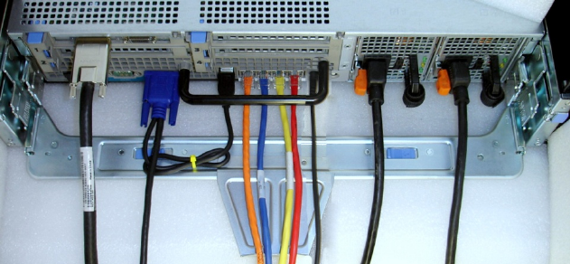
2.1InstallingtheCablestotheSystem
AttachtheCMAtraytothebackoftherailsasdescribedintheCMAInstallationInstructionsprovidedintheCMA
kit.Pluginallapplicablecablestotherearofthesystem.Verifythatallconnectionsaresecure.SeeFigure1.
Figure1:SystemwithCablesInstalled
CablingtheDell™PowerEdge™R710
Page3
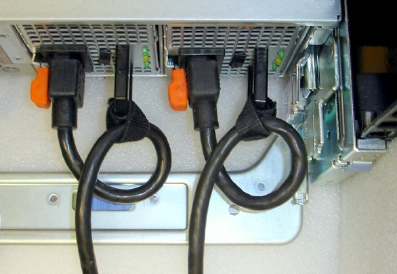
2.2RoutethePowerCablesThroughtheStrainReliefs
Afterthetrayandcablesareinstalled,routethepowercablesthroughthestrainreliefslocatedonthepower
supplyhandlesasshowninFigure2.
Figure2:RoutingPowerCablesThroughtheStrainReliefs
2.3RoutingtheCablesThroughtheCMA
NOTE:TheCMAcanbeinstalledoneithertherightorleftrearsideoftherails.MountingtheCMAontheside
oppositethepowersupplies(leftsidemount)isrecommended;otherwise,theCMAmustbedisconnectedinorder
toremovetheouterpowersupply.Referto“ReplacingaPowerSupplyonaPowerEdgeR710withCMA”laterin
thiswhitepaperfordetailsonpowersupplyreplacement.
NOTE:Forguidelinesonhowtoroutecableswithintherack,refertotheDellWhitePaper“BestPracticesGuide
forRackEnclosure”.
LeftSideMountingInstructions
1. InstalltheCMAontheleftrearsideoftherailsbyattachingbothCMAhousingstotheattachmentbracketson
therails.SeeFigure3.
2. RoutethecablesthroughtheCMAwhilekeepinganytwistingofthecablestoaminimum.Ifthecablebundle
includesaKVMdongle,placethedongleinsidetheCMAbasket.UsethehookandloopstrapsontheCMAto
securethecables.
CablingtheDell™PowerEdge™R710
Page4
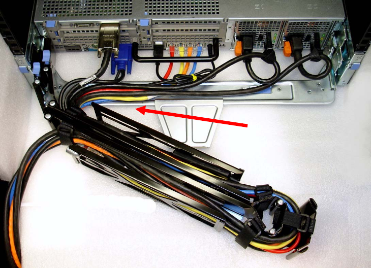
Figure3:RoutingtheCablesThroughtheCMA
3. OnceallthecablesareroutedthroughtheCMA,dressthecablesbetweenthebackofthesystemandthe
entranceoftheCMAwiththetiewrapsprovidedintheCMAkit.Thetiewrapsareshowninyellowinall
illustrations.
4. Clipofftheexcesslengthofmaterialfromthetiewrapsandmakesurethatthetiewrapsarepositionedto
avoidinterferencewithadjacentsystems.
5. ReturntheCMAtotheclosed(retracted)position.
6. Extendthesystemfromtheracktoverifythereissufficientslackinthecablesatboththeentranceandexitof
theCMA.
7. SeeFigure4foranexampleofacompletedleftsidemountedCMAinstallation.
Cables entering CMA should
have a small amount of slack
to avoid cable strain when
CMA is extended.
NOTE: Do not store excess
cable slack inside the CMA.
The cable may protrude
through the CMA causing
binding and potentially
damaging the cable.
CablingtheDell™PowerEdge™R710
Page5
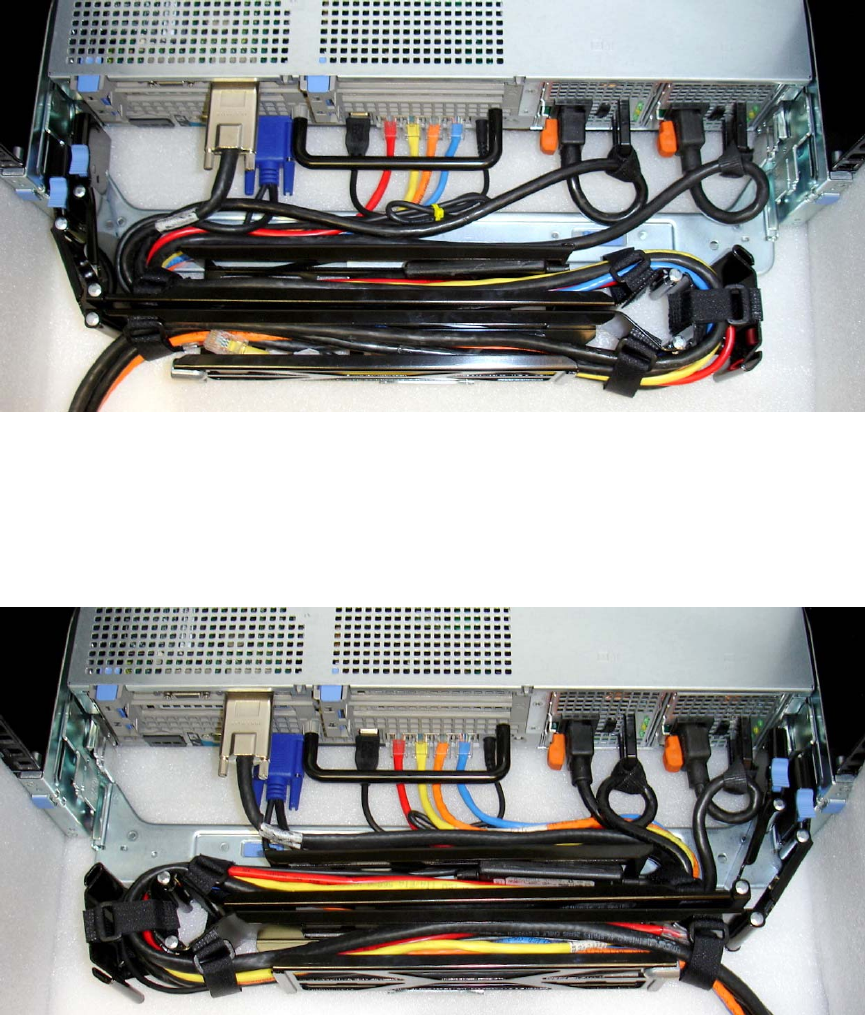
Figure4:CompletedLeftSideMountedCMAInstallation
RightSideMountingInstructions
InstalltheCMAontherightrearsideoftherailsbyattachingbothCMAhousingstotheattachmentbracketson
therails.Followsteps2‐6fromtheleftsidemountinginstructionsintheprevioussection.SeeFigure5foran
exampleofacompletedrightsidemountedCMAinstallation.
Figure5:CompletedRightSideMountedCMAInstallation
CablingaPowerEdgeR710withoutaCMA
NOTE:TheCMAontheDellPowerEdgeR710isoptional.WithouttheCMAinstalled,thesystemmustbepowered
downandallcablesdisconnectedbeforeitcanberemovedfromtherack.
3.1RoutingtheCables
1. Pluginallapplicablecablestotherearofthesystem,verifyingthatallconnectionsaresecure.

CablingtheDell™PowerEdge™R710
Page6
2. Usingthehookandloopstrapssuppliedwiththerailkit,bundlethecablesandsecurethemtoeithertheleft
railorrightrailCMAattachmentbracketsasdescribedintheRackInstallationGuide.SeeFigure6foran
exampleofpowercablessecuredtotherightCMAbracketanddatacablessecuredtotheleftCMAbracket.
3. Itisrecommendedthatthecablesbesecuredtotheouterbrackets,butcablesmaybesecuredtotheinner
bracketsifdesired.
Figure6:CableRoutingWithoutaCMA
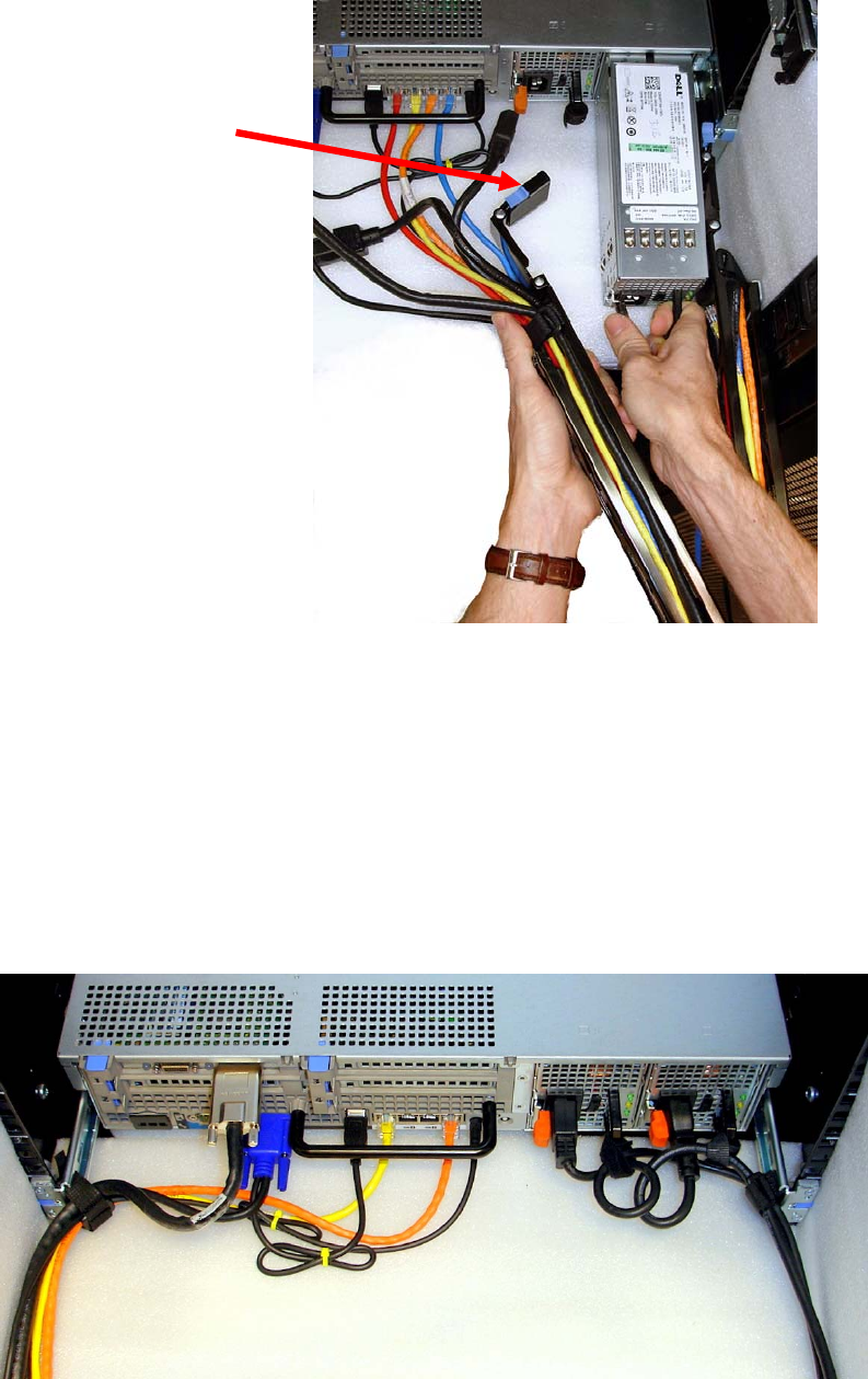
ReplacingaPowerSupplyonaPowerEdgeR710withCMA
1. RemovethetrayfromundertheCMAasdescribedintheCMAInstallationInstructionsprovidedwiththeCMA
kit.
2. SwingtheCMAintotheserviceposition.
3. Disconnectthepowercordfromthepowersupplyanddisengagethestrainrelief.
4. Removeandreplacethepowersupply
a. IftheCMAisattachedtotherightsideandtheouterpowersupplyneedstobereplaced,theinner
CMAattachmenthousingwillneedtobedisconnected.WhilesupportingtheCMAwithonehand,
removeandreplacethepowersupplywiththeotherhandasshowninFigure7.
b. IftheCMAisattachedtotherightsideandtheinnerpowersupplyneedstobereplaced,theCMA
doesnotneedtobedisconnected.
c. IftheCMAisattachedtotheleftside,bothpowersuppliescanberemovedwithoutdisconnecting
theCMA.
5. Pluginthepowercord.
6. Re‐engagethestrainrelief.
7. ReplacetheCMAsupporttray.
8. ReturntheCMAtotheclosed(retracted)position.
CablingtheDell™PowerEdge™R710
Page7
Figure7:ReplacingOuterPowerSupply
CablingaPowerEdgeR710InstalledinStaticRails
NOTE:TheCMAisonlycompatiblewithslidingrails,andnotwithstaticrails.
1. FollowtheinstructionsintheRackInstallationGuideincludedinthestaticrailkittoinstalltheserverintoa2‐
postor4‐postrack.
2. Verifythatthehookandloopsstrapsprovidedwiththestaticrailkitareinstalledtotherearoftherails.
3. Pluginallapplicablecablestotherearofthesystemandverifythatallconnectionsaresecure.
4. Usingthehookandloopstrapssuppliedwiththerailkit,bundlethecablesandsecurethemtoeithertheleft
railorrightrailasdescribedintheRackInstallationGuide.SeeFigure8.
Figure8:CablingaSystemInstalledinStaticRails
Inner CMA attachment
housing has been
disconnected
