Dell N03G Internet of Things Gateway User Manual
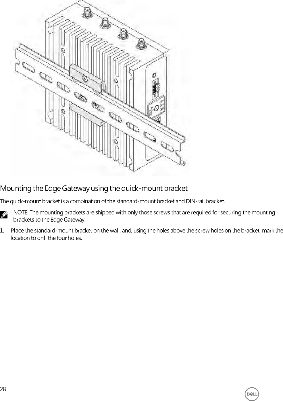
Dell Inc. Internet of Things Gateway
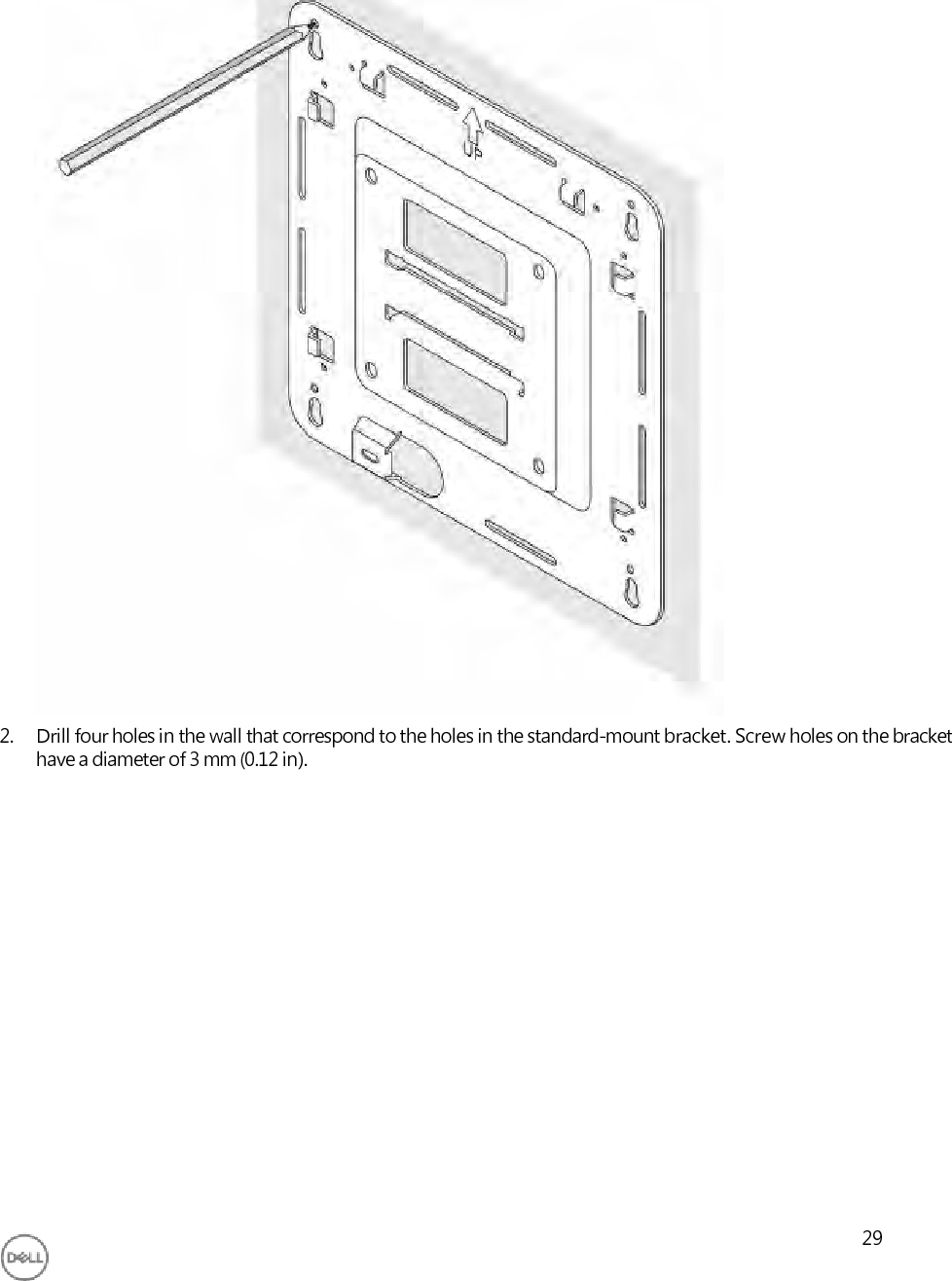
UserManual.wiki
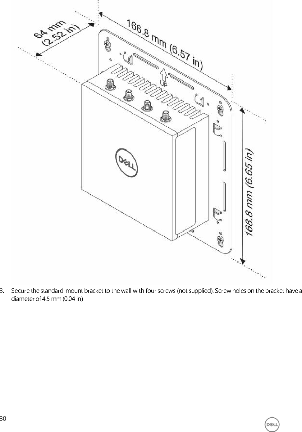
>
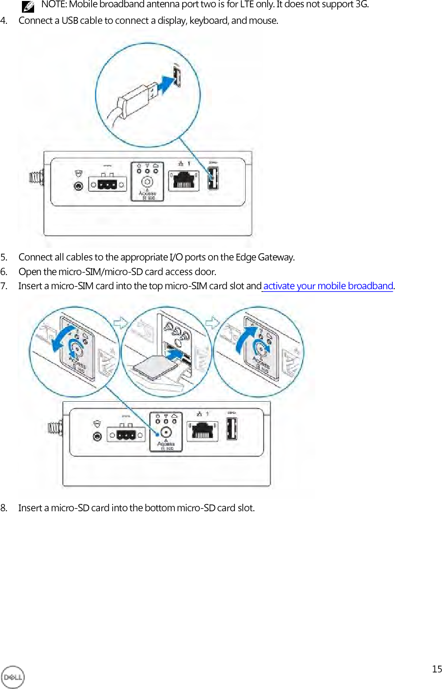
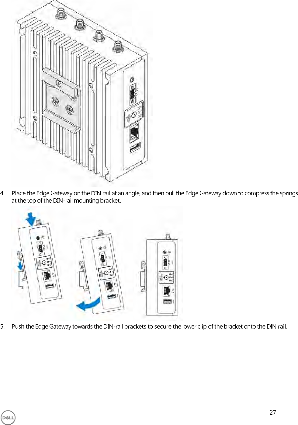
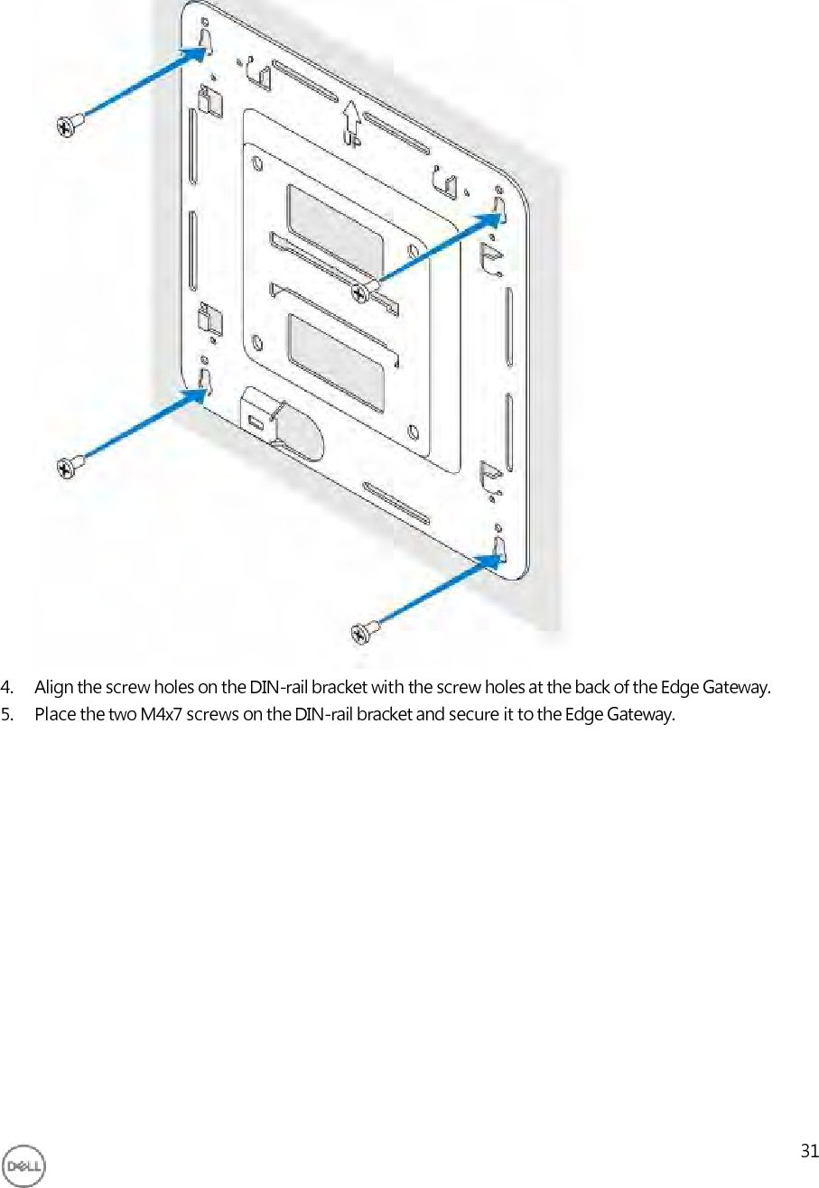
Dell
>
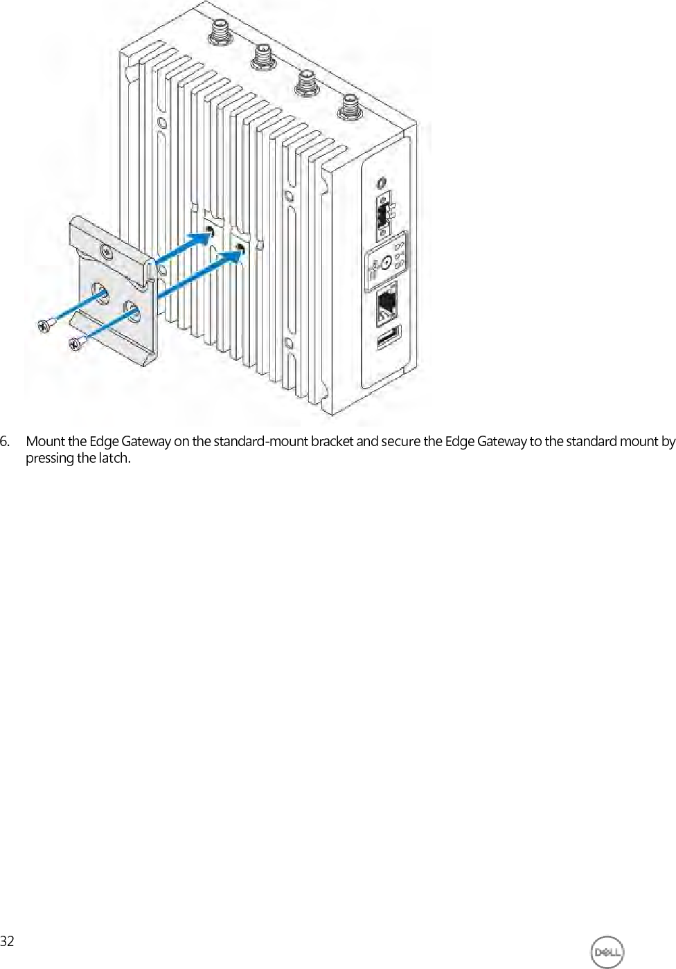
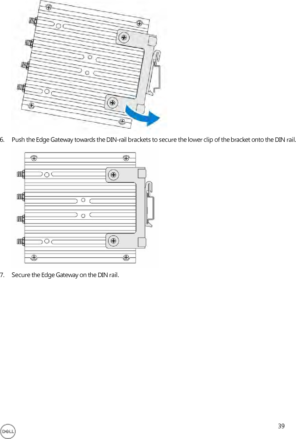
N03G User Manual
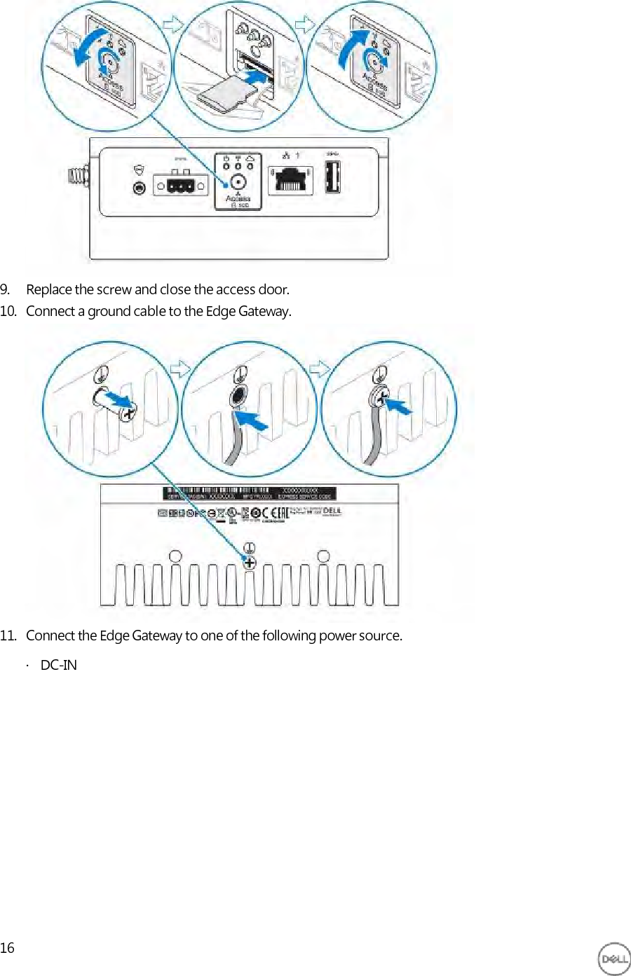
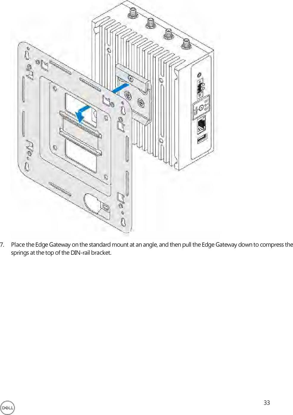
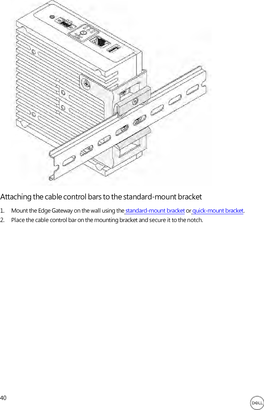
User manual
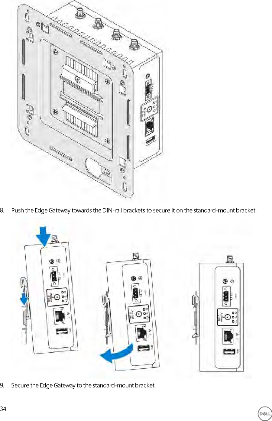
Navigation menu
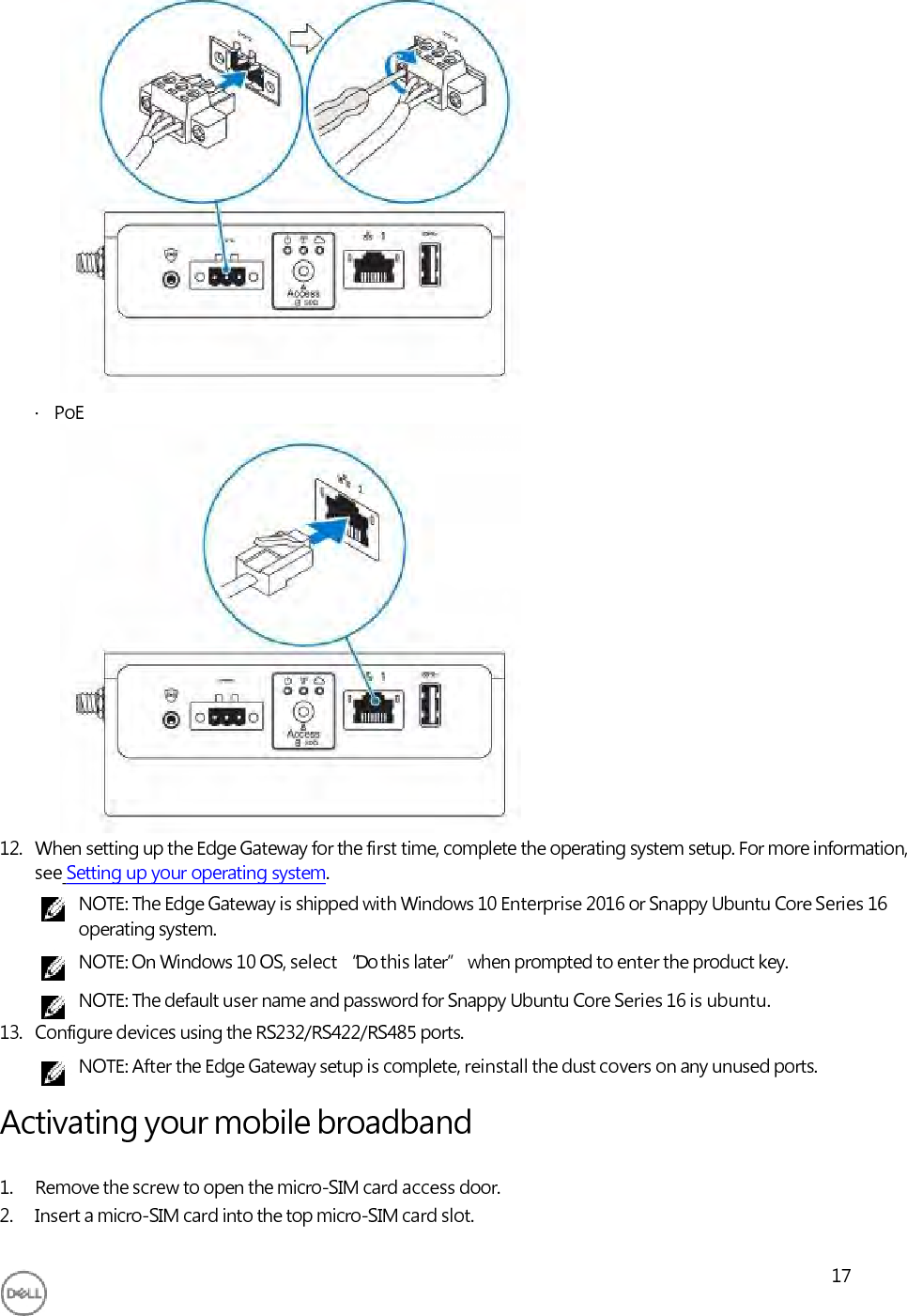
Upload a User Manual
Namespaces
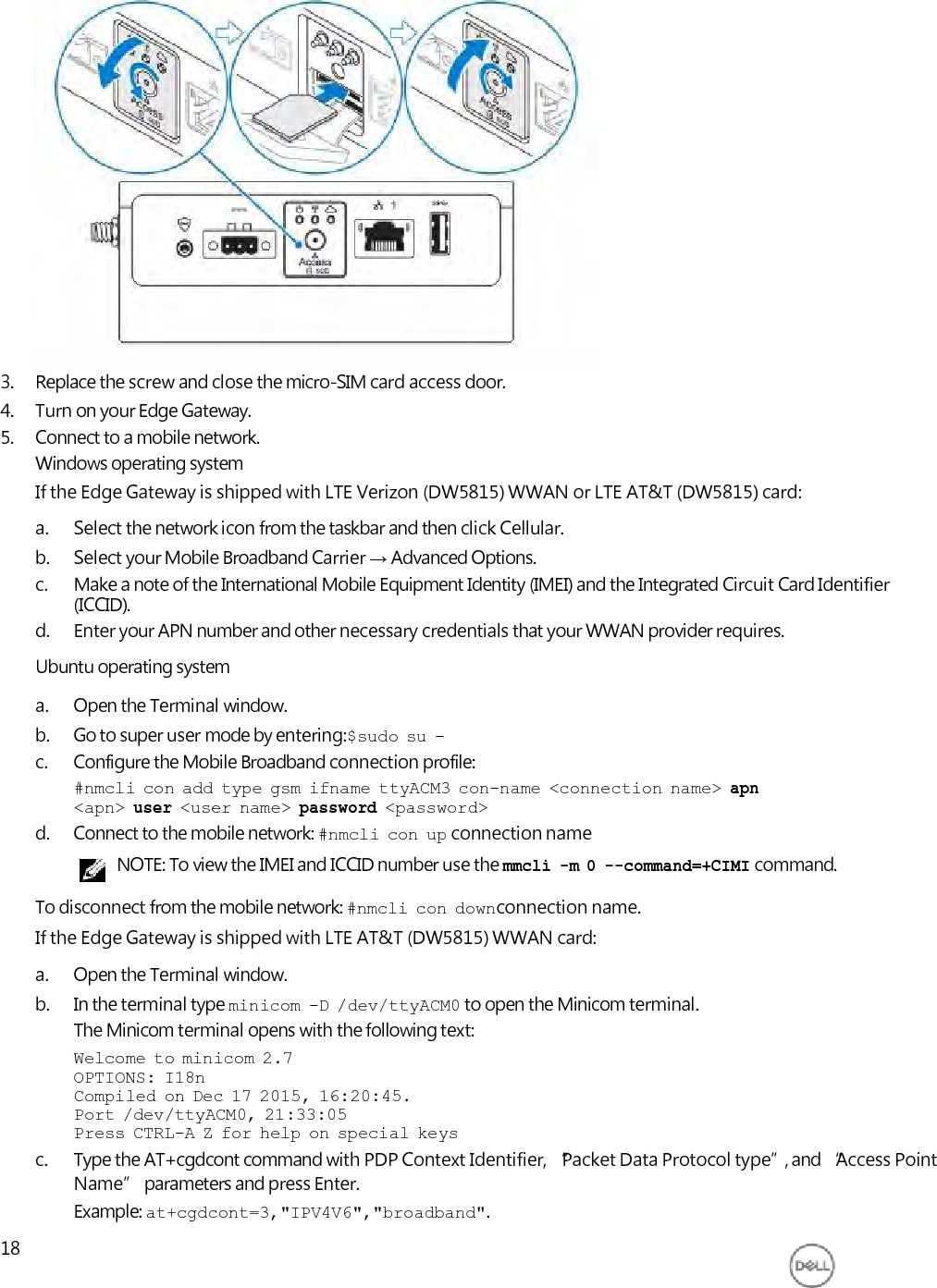
Wiki Guide
HTML
PDF
Info
Views
User Manual
Discussion / Help
Navigation

![FCC caution:· Any changes or modifications not expressly approved by the party responsible for compliance could void the user'sauthority to operate this equipment.· This transmitter must not be co-located or operating in conjunction with any other antenna or transmitter.Radiation exposure statement:This equipment complies with FCC radiation exposure limits for an uncontrolled environment. This equipment should beinstalled and operated with a minimum distance of 20 cm between the active transceiver and your body.NOTE: The country code selection is for a non-US model only and is not available to all US model. Per FCCregulation, all WiFi products marketed in the US must be fixed to US operation channels only.Industry Canada statement This device complies with Industry Canada license-exempt RSS standard(s). Operation is subject to the following twoconditions:1. this device may not cause interference, and2. this device must accept any interference, including interference that may cause undesired operation of the device.Le présent appareil est conforme aux CNR d'Industrie Canada applicables aux appareils radio exempts de licence.L'exploitation est autorisée aux deux conditions suivantes:1. l'appareil ne doit pas produire de brouillage, et2. l'utilisateur de l'appareil doit accepter tout brouillage radioélectrique subi, même si le brouillage est susceptibled'en compromettre le fonctionnement.This Class A digital apparatus complies with Canadian ICES-003.Cet appareil numérique de la classe A est conforme à la norme NMB-003 du Canada.This device complies with RSS-310 of Industry Canada. Operation is subject to the condition that this device does not cause harmful interference.Cet appareil est conforme à la norme RSS-310 d'Industrie Canada. L'opération est soumise à la condition que cet appareil ne provoque aucune interférence nuisible.This device and its antenna(s) must not be co-located or operating in conjunction with any other antenna or transmitter, except tested built-in radios.Cet appareil et son antenne ne doivent pas être situés ou fonctionner en conjonction avec une autre antenne ou un autre émetteur, exception faites des radios intégrées qui ont été testées.The County Code Selection feature is disabled for products marketed in the US/Canada.La fonction de sélection de l'indicatif du pays est désactivée pour les produits commercialisés aux États-Unis et au Canada.Radiation Exposure Statement: This equipment complies with IC radiation exposure limits set forth for an uncontrolled environment. This equipment should be installed and operated with minimum distance of 20 cm between the active transceiver and your body.Déclaration d'exposition aux radiations: Cet équipement est conforme aux limites d'exposition aux rayonnements IC établies pour un environnement non contrôlé. Cet équipement doit être installé et utilisé avec un minimum de 20 cm de distance entre la source de rayonnement et votre corps.This radio transmitter (1514B-N03G) has been approved by Industry Canada to operate with the antenna types listed below with the maximum permissible gain indicated. Antenna types not included in this list, having a gain greater than the maximum gain indicated for that type, are strictly prohibited for use with this device. Brand Model Antenna Type Gain Taoglas [wlan] TS.07.2113B Monopole 1.3 (dBi) Taoglas [Zigbee] GW.15.1113 Monopole 0.1 (dBi)](https://usermanual.wiki/Dell/N03G/User-Guide-3394504-Page-12.png)
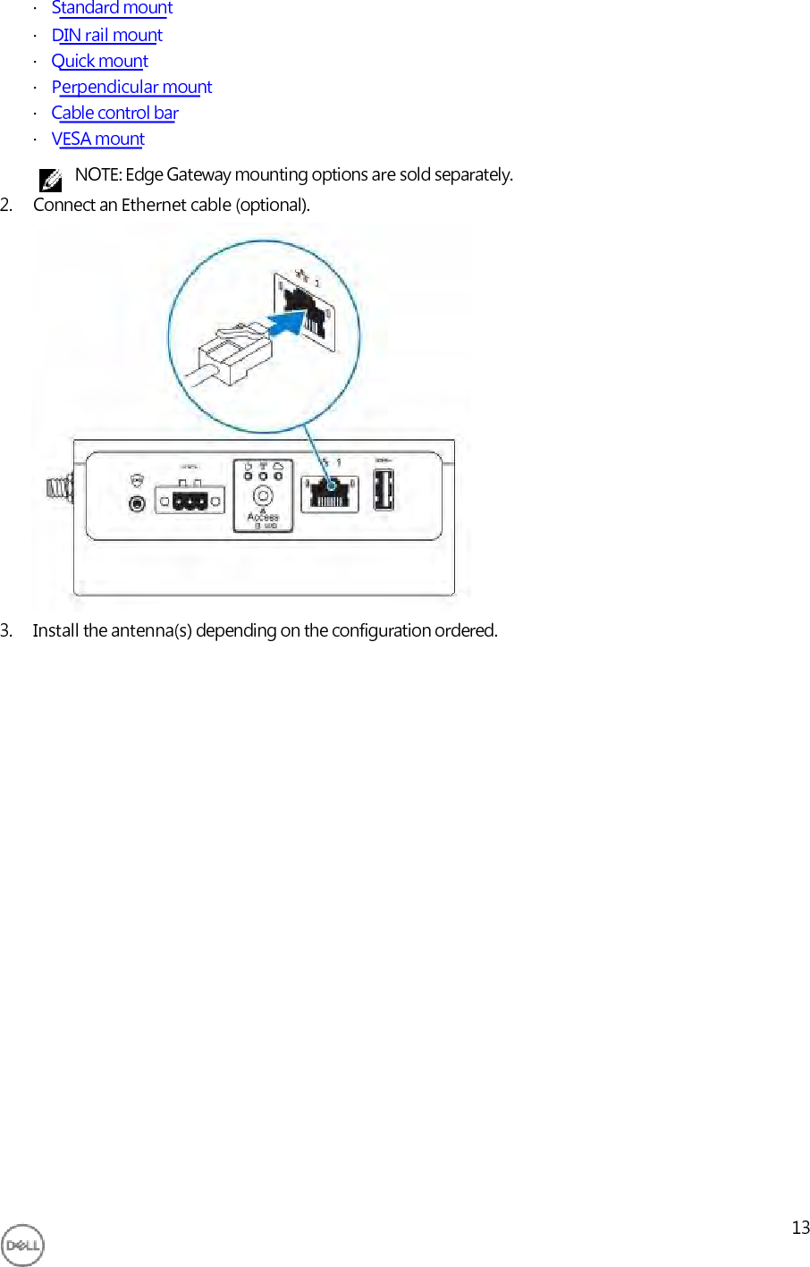
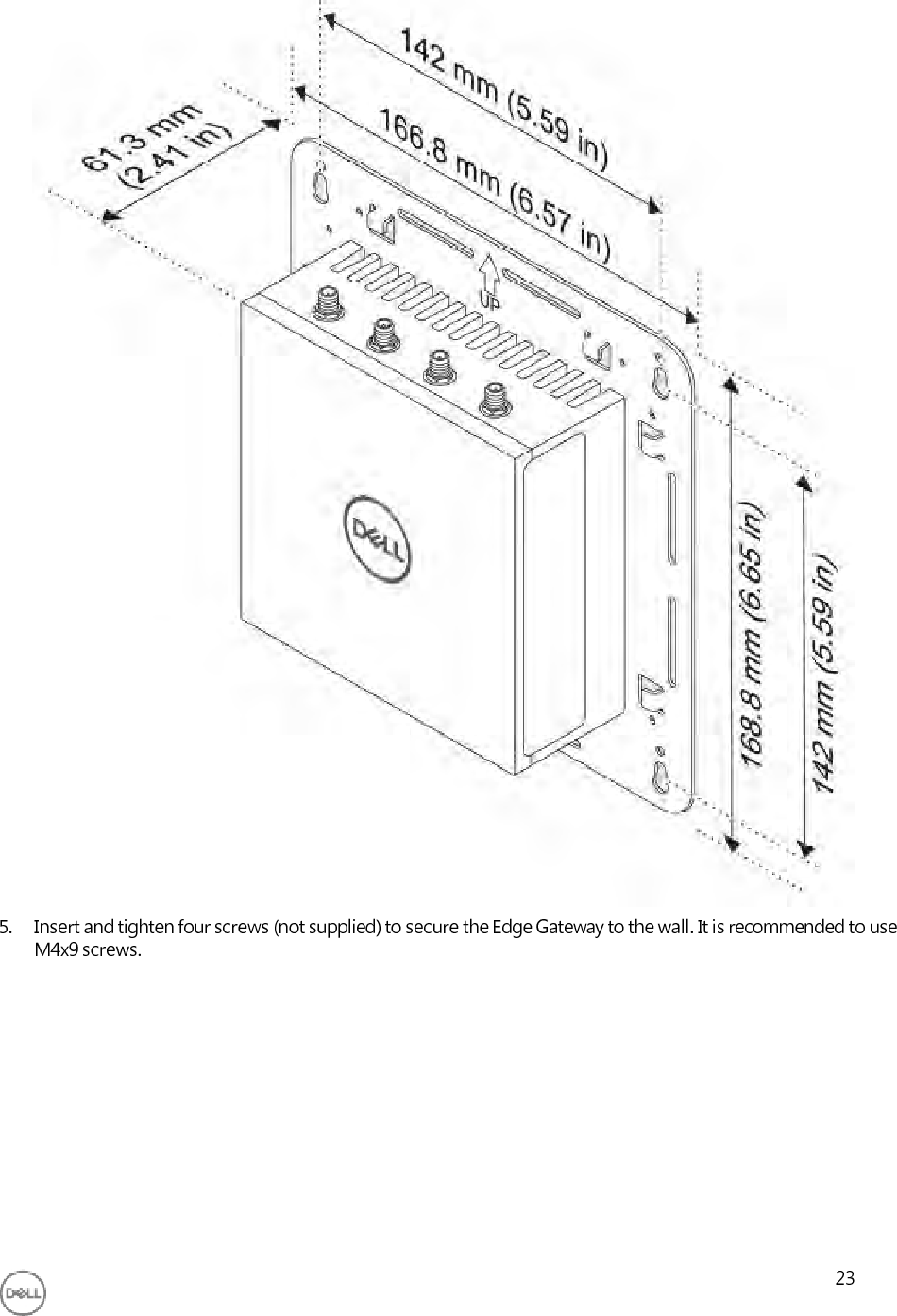
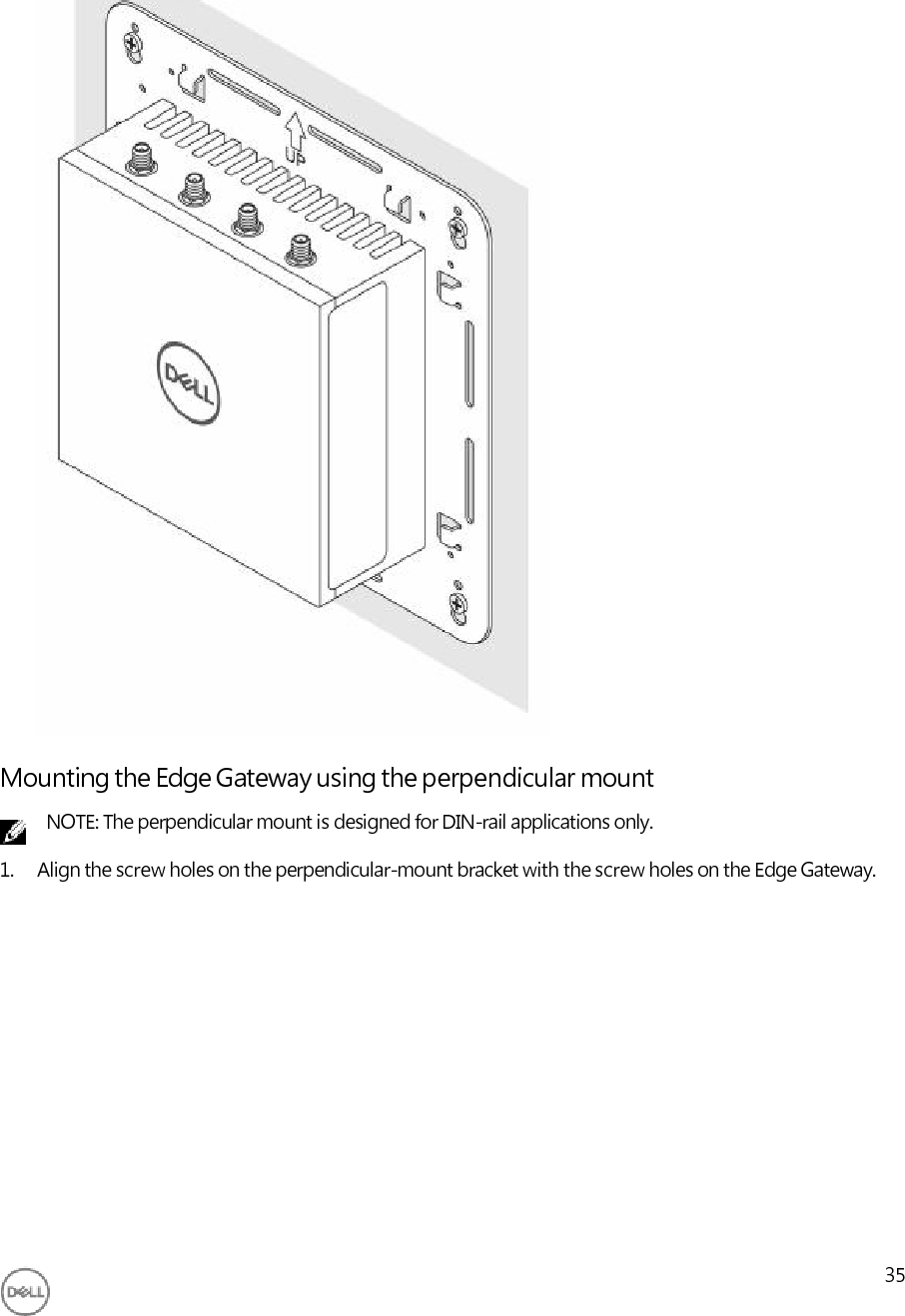
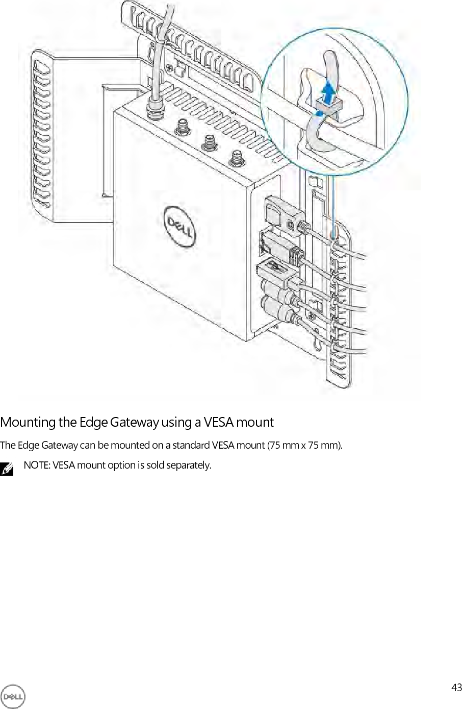
![Le présent émetteur radio (1514B-N03G) a été approuvé par Industrie Canada pour fonctionner avec les types d'antenne énumérés ci-dessous et ayant un gain admissible maximal et l'impédance requise pour chaque type d'antenne. Les types d'antenne non inclus dans cette liste, ou dont le gain est supérieur au gain maximal indiqué, sont strictement interdits pour l'exploitation de l'émetteur. Brand Model Antenna Type Gain Taoglas [wlan] TS.07.2113B Monopole 1.3 (dBi) Taoglas [Zigbee] GW.15.1113 Monopole 0.1 (dBi) Under Industry Canada regulations, this radio transmitter may only operate using an antenna of a type and maximum (or lesser) gain approved for the transmitter by Industry Canada. To reduce potential radio interference to other users, the antenna type and its gain should be so chosen that the equivalent isotropically radiated power (e.i.r.p.) is not more than that necessary for successful communication. Conformément à la réglementation d'Industrie Canada, le présent émetteur radio peut fonctionner avec une antenne d'un type et d'un gain maximal (ou inférieur) approuvé pour l'émetteur par Industrie Canada. Dans le but de réduire les risques de brouillage radioélectrique à l'intention des autres utilisateurs, il faut choisir le type d'antenne et son gain de sorte que la puissance isotrope rayonnée équivalente (p.i.r.e.) ne dépasse pas l'intensité nécessaire à l'établissement d'une communication satisfaisante. Setting up your Edge Gateway 1. Install the Edge Gateway using one of the following mounting options: 12](https://usermanual.wiki/Dell/N03G/User-Guide-3394504-Page-13.png)

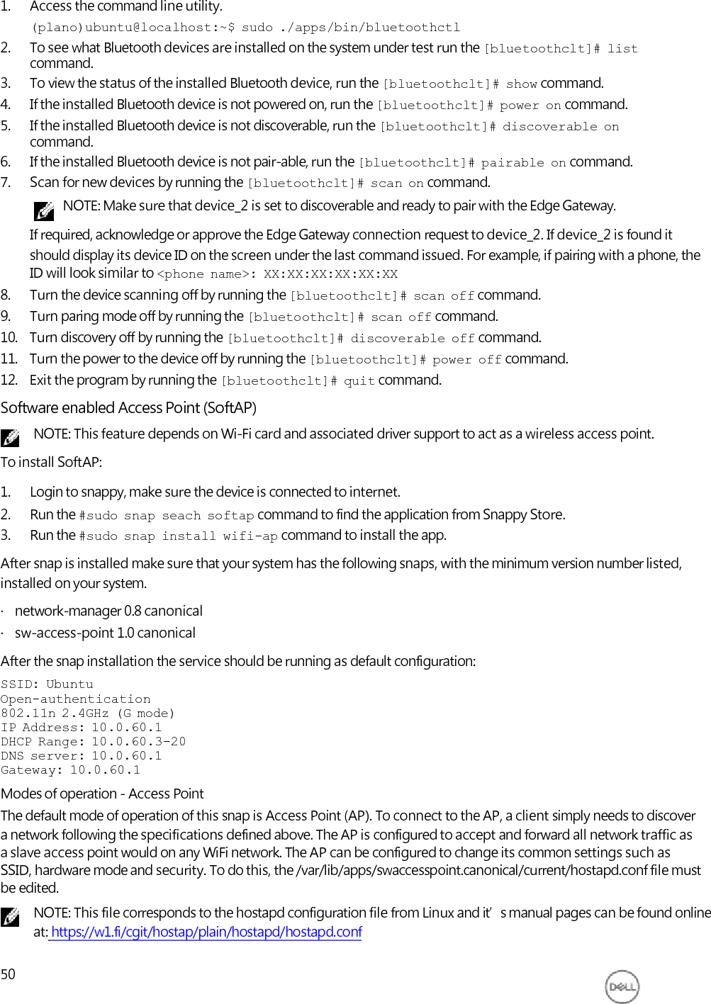
![1. Access the command line utility. (plano)ubuntu@localhost:~$ sudo ./apps/bin/bluetoothctl 2. To see what Bluetooth devices are installed on the system under test run the [bluetoothclt]# list command. 3. To view the status of the installed Bluetooth device, run the [bluetoothclt]# show command. 4. If the installed Bluetooth device is not powered on, run the [bluetoothclt]# power on command. 5. If the installed Bluetooth device is not discoverable, run the [bluetoothclt]# discoverable on command. 6. If the installed Bluetooth device is not pair-able, run the [bluetoothclt]# pairable on command. 7. Scan for new devices by running the [bluetoothclt]# scan on command. NOTE: Make sure that device_2 is set to discoverable and ready to pair with the Edge Gateway. If required, acknowledge or approve the Edge Gateway connection request to device_2. If device_2 is found it should display its device ID on the screen under the last command issued. For example, if pairing with a phone, the ID will look similar to <phone name>: XX:XX:XX:XX:XX:XX 8. Turn the device scanning off by running the [bluetoothclt]# scan off command. 9. Turn paring mode off by running the [bluetoothclt]# scan off command. 10. Turn discovery off by running the [bluetoothclt]# discoverable off command. 11. Turn the power to the device off by running the [bluetoothclt]# power off command. 12. Exit the program by running the [bluetoothclt]# quit command. Software enabled Access Point (SoftAP) NOTE: This feature depends on Wi-Fi card and associated driver support to act as a wireless access point. To install SoftAP: 1. Login to snappy, make sure the device is connected to internet. 2. Run the #sudo snap seach softap command to find the application from Snappy Store. 3. Run the #sudo snap install wifi-ap command to install the app. After snap is installed make sure that your system has the following snaps, with the minimum version number listed, installed on your system. · network-manager 0.8 canonical · sw-access-point 1.0 canonical After the snap installation the service should be running as default configuration: SSID: Ubuntu Open-authentication 802.11n 2.4GHz (G mode) IP Address: 10.0.60.1 DHCP Range: 10.0.60.3-20 DNS server: 10.0.60.1 Gateway: 10.0.60.1 Modes of operation - Access Point The default mode of operation of this snap is Access Point (AP). To connect to the AP, a client simply needs to discover a network following the specifications defined above. The AP is configured to accept and forward all network traffic as a slave access point would on any WiFi network. The AP can be configured to change its common settings such as SSID, hardware mode and security. To do this, the /var/lib/apps/swaccesspoint.canonical/current/hostapd.conf file must be edited. NOTE: This file corresponds to the hostapd configuration file from Linux and it’s manual pages can be found online at: https://w1.fi/cgit/hostap/plain/hostapd/hostapd.conf 50](https://usermanual.wiki/Dell/N03G/User-Guide-3394504-Page-51.png)
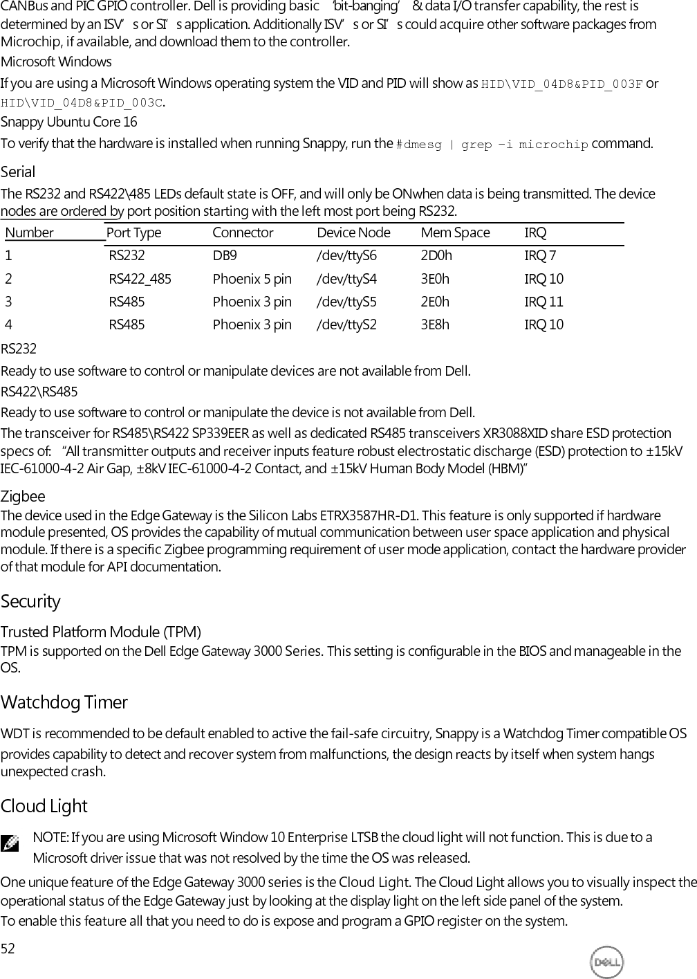
![1. Expose the GPIO register. (plano)ubuntu@localhost:~$ sudo sh -c 'echo 346 > /sys/class/gpio/export; sleep 2; echo out > /sys/class/gpio/gpio346/direction' 2. Command to turn on the LED. (plano)ubuntu@localhost:~$ sudo sh -c 'echo 1 > /sys/class/gpio/gpio346/ value' 3. Command to turn off the LED. (plano)ubuntu@localhost:~$ sudo sh -c 'echo 0 > /sys/class/gpio/gpio346/ value' Restoring Snappy Ubuntu Core Series 16 CAUTION: Following the steps deletes all the data on your system. The following steps refer to different methods through which the Snappy Ubuntu Core Series 16 operating system can be restored to the factory image. External storage On supported platforms, you can download the factory image from www.dell.com to restore your Edge Gateway by external media kit. For more information, see www.dell.com/support/article/us/en/19/SLN301761. Factory OS recovery image You can restore Snappy Ubuntu Core Series 16 on the Edge Gateway using the recovery OS image on the boot partition. Reset the system back to the factory image if you encounter any of the following situations: · You are unable to start the operating system. · The operating system is damaged. Connect a keyboard, mouse, and monitor to the Edge Gateway, or connect to the Edge Gateway through a KVM session. 1. Turn on the system. 2. Press F12 when the Dell logo is displayed on the screen to enter the boot menu. 3. Select Factory Restore from the boot menu. CAUTION: Following the step deletes all the data on your system. 4. Press Y when prompted Factory Restore will delete all user data, are you sure? [Y/N]. System restore starts and reinstalls the OS on your Edge Gateway. Flashing a new OS Image Pre-requisites · USB 2.0 or USB 3.0 flash drive (4 GB min.) · Ubuntu Snappy Core 16 ISO. NOTE: You can download the latest version of the Ubuntu ISO file from http://releases.ubuntu.com. · A released Snappy Ubuntu Core 16 image from Dell/Canonical: <unique name>.img.xz · Dell Edge Gateway 3000 series hardware · USB keyboard · USB mouse · Ethernet cable (x2) · Ubuntu workstation with Ubuntu 14.04 release or higher. 53](https://usermanual.wiki/Dell/N03G/User-Guide-3394504-Page-54.png)