User manual

Dell Edge Gateway 3002
Installation and Operation Manual
Regulatory Model: N03G
Regulatory Type: N03G001

Notes, cautions, and warnings
NOTE: A NOTE indicates important information that helps you make better use of your product.
CAUTION: A CAUTION indicates either potential damage to hardware or loss of data and tells you how to avoid the
problem.
WARNING: A WARNING indicates a potential for property damage, personal injury, or death.
Copyright
©
2016 Dell Inc. or its subsidiaries. All rights reserved. Dell, EMC, and other trademarks are trademarks of Dell Inc. or its
subsidiaries. Other trademarks may be trademarks of their respective owners.
2016 - 11
Rev. A00

Contents
1 Overview...................................................................................................................................... 5
2 System views.............................................................................................................................. 6
Top view................................................................................................................................................................... 6
Bottom view.............................................................................................................................................................. 7
Left view................................................................................................................................................................... 7
Right view................................................................................................................................................................. 8
3 Installing your Edge Gateway................................................................................................ 10
Professional installation instructions..................................................................................................................... 10
Instructions d'installation professionnelles........................................................................................................... 11
Federal Communication Commission interference statement............................................................................... 11
Industry Canada statement.................................................................................................................................... 12
Setting up your Edge Gateway............................................................................................................................... 12
Activating your mobile broadband......................................................................................................................... 17
Mounting your Edge Gateway................................................................................................................................ 19
Mounting the Edge Gateway using the standard-mount bracket.................................................................... 19
Mounting the Edge Gateway on a DIN rail using the DIN-rail bracket........................................................... 25
Mounting the Edge Gateway using the quick-mount bracket......................................................................... 28
Mounting the Edge Gateway using the perpendicular mount......................................................................... 35
Attaching the cable control bars to the standard-mount bracket................................................................... 40
Mounting the Edge Gateway using a VESA mount.......................................................................................... 43
4 Setting up your operating system.......................................................................................... 45
Windows 10 Enterprise LTSB 2016......................................................................................................................... 45
Overview.......................................................................................................................................................... 45
Setting up Windows 10 Enterprise LTSB 2016................................................................................................. 45
Boot up and login............................................................................................................................................. 45
Windows 10 IOT Enterprise LTSB 2016 basic functions.................................................................................. 45
Snappy Ubuntu Core Series 16............................................................................................................................... 46
Overview.......................................................................................................................................................... 46
Boot up and log in............................................................................................................................................ 46
Updating operating system and applications.................................................................................................. 47
Useful commands............................................................................................................................................ 48
Network Communication Interfaces................................................................................................................ 49
Additional Communication Interfaces............................................................................................................. 51
Security............................................................................................................................................................ 52
Watchdog Timer.............................................................................................................................................. 52
Cloud Light....................................................................................................................................................... 52
Restoring Snappy Ubuntu Core Series 16........................................................................................................ 53
3

Flashing a new OS Image................................................................................................................................ 53
Flashing the BIOS................................................................................................................................................... 54
Edge Gateway CAN Module Functions.................................................................................................................. 54
5 References................................................................................................................................ 56
6 Contacting Dell......................................................................................................................... 57
4

Overview
1
5
The
Edge
Gateway
3000
Series
is
an
Internet
of
Things
device.
It
is
mounted
at
the
edge
of
a
network,
enabling
you
to
collect,
secure,
analyze,
and
act
on
data
from
multiple
devices
and
sensors.
It
enables
you
to
connect
with
devices
used
in
transportation,
building
automation,
manufacturing,
and
other
applications.
The
Edge
Gateway
has
a
low-power
architecture,
which
is
capable
of
supporting
industrial
automation
workloads
while
remaining
fanless
for
environmental
and
reliability
requirements.
It
supports
Windows
10
IoT
Enterprise
LTSB
2016
and
Snappy
Ubuntu
Core
Series
16
operating
systems.
For FCC ID: E2K-N03G & IC: 1514B-N03G, it supports WiFi/BT 4.0 LE/BT+EDR/Zigbee
without 3G/LTE function.
System
views
2
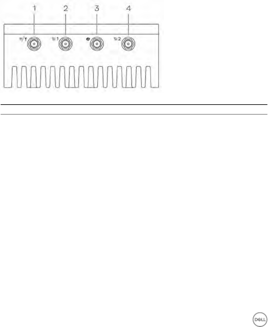
Top
view
Table
1.
Top
view
Features
1 Wireless
LAN/Bluetooth/GPS
port Connect
the
antenna
to
increase
the
range
and
strength
of
wireless/bluetooth/satellite
signals.
2 Mobile
broadband
antenna
port
one
(3G/LTE)
Connect
a
mobile
broadband
antenna
to
increase
the
range
and
strength
of
mobile
broadband
signals.
3 ZigBee
antenna
port Connect
a
ZigBee
antenna
for
intermittent
data
transmissions
from
a
ZigBee-compliant
sensor
or
input
device.
4 Mobile
broadband
antenna
port
two
(LTE
only)
Connect
a
mobile
broadband
antenna
to
increase
the
range
and
strength
of
mobile
broadband
signals.
6
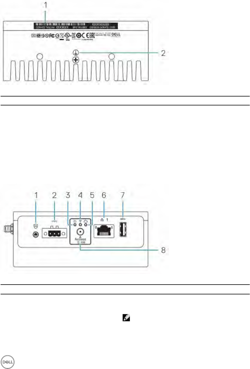
Bottom
view
Table
2.
Bottom
view
Features
1
Service
Tag
label
The
Service
Tag
is
a
unique
alphanumeric
identifier
that
allows
Dell
Service
technicians
to
identify
the
hardware
components
in
your
Edge
Gateway
and
access
warranty
information.
2
Earth
A
large
conductor
attached
to
one
side
of
the
power
supply,
which
serves
as
the
common
return
path
for
current
from
many
different
components
in
the
circuit.
Left
view
Table
3.
Left
view
Features
1
Connector
for
external
enclosure
chassis
intrusion
switch
(optional)
An
intrusion
event
is
triggered
when
the
enclosure
(in
which
the
Edge
Gateway
is
installed)
is
opened.
NOTE:
External
enclosure
is
sold
separately.
7
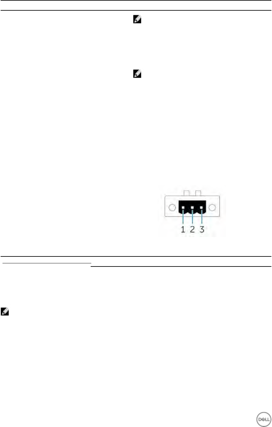
Features
NOTE: A intrusion event is triggered by a third-party
enclosure to the Edge Gateway through a sensor. The
sensor should have a cable, which is compatible with
the intrusion switch connector on the Edge Gateway.
2 Power/Ignition port Connect a 12-57V DC power cable for supplying power to
the Edge Gateway.
NOTE: Power cable is sold separately.
3 Power status light Indicates the power status.
4 Wireless LAN/Bluetooth status light Indicates if WLAN/Bluetooth is ON or OFF.
5 Cloud-connection status light Indicates the cloud connection status.
6 Ethernet port one (PoE) Connect an Ethernet (RJ45) cable for network access.
Provides data transfer speeds up to 10/100 Mbps. Also
supports Power over Ethernet (IEEE 802.3af compliant
PSE3.0).
7 USB 3.0 port Connect a USB enablight device. Provides data transfer
speeds up to 5 Gbps.
8 micro-SIM/SD card access door Insert a micro-SIM and/or SD card.
The following figure shows the power connector pin number mapping. The following table
shows the power connector pin definition details.
Table 4. Power connector pin definition details
Pin Signal Function
1 Power 12–57 VDC power
2 GND Ground
3 IGN 9–37 VDC ignition
NOTE: Pin 3 is connected to a vehicle's ignition status indicator (optional).
Right view
8
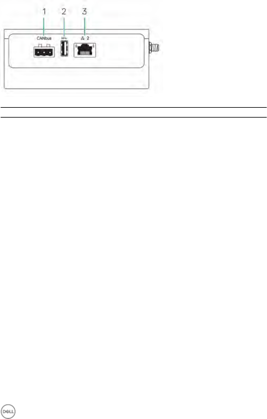
Table 5. Right view — 3002
Features
1 CANbus port Enables the CANbus connection.
2 USB 2.0 port Connect a USB enabled device. Provides data transfer
speeds up to 480 Mbps.
3 Ethernet port two (Non-PoE) Connect an Ethernet (RJ45) cable for network access.
Provides data transfer speeds up to 10/100 Mbps.
9
Installing
your
Edge
Gateway
3
WARNING:
Before
you
begin
any
of
the
procedures
in
this
section,
read
the
safety
information
that
shipped
with
your
system.
For
additional
best
practices
information,
go
to
www.dell.com/regulatory_compliance.
WARNING:
The
Edge
Gateway
is
to
be
installed
by
knowledgeable,
skilled
persons
familiar
with
local
codes
and
regulations.
WARNING:
The
Edge
Gateway
is
not
designed
for
use
in
wet
environments.
If
the
Edge
Gateway
is
to
be
installed
in
a
wet
environment,
it
must
be
installed
in
a
panel
box
or
enclosure
with
an
Ingress
Protection
(IP)
rating
of
IP54,
IP65,
or
higher,
depending
on
the
location
and
environment.
WARNING:
To
reduce
the
risk
of
electric
shock,
power
to
the
DC+
and
DC-
terminals
must
be
provided
by
a
power
supply
or
transformer/rectifier
circuit
that
is
designed
with
double-insulation.
The
power
supply
or
power
circuit
source
must
comply
with
local
codes
and
regulations;
for
example,
in
the
USA,
NEC
Class
2
(SELV/limited
energy
circuit,
or
LPS
circuitry).
Note
that
if
powered
by
a
battery,
double-insulation
is
not
required.
WARNING:
When
installing
the
Edge
Gateway,
the
responsible
party
or
integrator
shall
use
the
12-57
V
DC
or
Power
over
Ethernet
(PoE)
power
source
already
present
as
part
of
the
client’s
installation.
WARNING:
When
installing
the
Edge
Gateway,
use
a
cable
appropriate
for
the
load
currents:
3-core
cable
rated
5
A
at
90°C
(194
°F)
minimum,
which
conform
to
either
IEC
60227
or
IEC
60245.
The
system
accepts
cables
from
0.8
mm
to
2
mm.
The
maximum
operating
temperature
of
the
Edge
Gateway
is
70
⁰
C
(158°F).
Do
not
exceed
this
maximum
temperature
while
operating
the
Edge
Gateway
inside
an
enclosure.
Internal
heating
of
the
Edge
Gateway
electronics,
other
electronics,
and
the
lack
of
ventilation
inside
an
enclosure
can
cause
the
operating
temperature
of
the
Edge
Gateway
to
be
greater
than
the
outside
ambient
temperature.
Continuous
operation
of
the
Edge
Gateway
at
temperatures
greater
than
70
⁰
C
(158°F)
may
result
in
an
increased
failure
rate
and
a
reduction
of
the
product
life.
Ensure
that
the
maximum
operating
temperature
of
the
Edge
Gateway
when
placed
inside
an
enclosure
is
70
⁰
C
(158°F)
or
less.
WARNING:
The
symbol
indicates
hot
surface
or
adjacent
hot
surface
that
can
obtain
temperature
during
normal
use
that
can
cause
a
burn.
Allow
equipment
to
cool
off
or
use
protective
gloves
when
handling
to
reduce
risk
of
a
burn.
WARNING:
Always
ensure
that
the
available
power
source
matches
the
required
input
power
of
the
Edge
Gateway.
Check
the
input
power
markings
next
to
power
connector(s)
before
making
connections.
The
12-57
V
DC
or
PoE
power
source
must
be
compliant
with
local
Electrical
Codes
and
Regulations.
WARNING:
To
ensure
the
protection
provided
by
Edge
Gateway
is
not
impaired,
do
not
use
or
install
the
system
in
any
manner
other
than
what
is
specified
in
this
manual.
WARNING:
If
a
battery
is
included
as
part
of
the
system
or
network,
the
battery
must
be
installed
within
an
appropriate
enclosure
in
accordance
with
local
fire
and
electrical
codes
and
laws.
WARNING:
The
system
is
for
installation
in
a
suitable
industrial
enclosure
(provides
electrical,
mechanical,
and
fire
hazard
protection).
WARNING:
The
core
module
only
can
be
wall-mounted
(without
the
need
for
an
additional
enclosure).
Professional
installation
instructions
Installation
personnel
This
product
is
designed
for
specific
applications
and
needs
to
be
installed
by
qualified
personnel
with
RF
and
regulatory-related
knowledge.
The
general
user
shall
not
attempt
to
install
or
change
the
setting.
10

Installation location
The product shall be installed at a location where the radiating antenna is kept 20 cm from nearby persons in its normal
operation condition in order to meet regulatory RF exposure requirements.
External antenna
Use only approved antenna(s). Non-approved antenna(s) may produce spurious or excessive RF transmitting power
which may lead to a violation of FCC/IC limits.
Installation procedure
Refer to user’s manual for installation instructions.
WARNING: Carefully select the installation position and make sure that the final output power does not exceed the
limits described in the product’s documentation. The violation of these rules could lead to serious federal
penalties.
Instructions d'installation professionnelles
Le personnel d'installation
Ce produit est conçu pour des applications spécifiques et doit être installé par un personnel qualifié avec RF et
connaissances connexes réglementaire. L'utilisateur ne doit pas tenter générale d'installer ou de modifier le réglage.
Lieu d'installation
Le produit doit être installé à un endroit où l'antenne de rayonnement est maintenue à 20 cm de personnes à proximité
dans son état de fonctionnement normal, afin de répondre aux exigences réglementaires d'exposition aux
radiofréquences.
Antenne externe
Utilisez uniquement l'antenne(s) qui ont été approuvés par le demandeur. Antenne (s) peuvent produire de l'énergie RF
parasite indésirable ou excessive transmission qui peut conduire à une violation des normes de la FCC / IC est interdite
et non-approuvé.
Procédure d'installation
ATTENTION: S'il vous plaît choisir avec soin la position d'installation et assurez-vous que la puissance de sortie final ne
dépasse pas les limites fixées dans les règles pertinentes. La violation de ces règles pourrait conduire à des sanctions
fédérales graves.
Federal Communication Commission interference statement
This device complies with Part 15 of the FCC Rules. Operation is subject to the following two conditions: (1) This device
may not cause harmful interference, and (2) this device must accept any interference received, including interference
that may cause undesired operation.
This equipment has been tested and found to comply with the limits for a Class A digital device, pursuant to Part 15 of
the FCC Rules. These limits are designed to provide reasonable protection against harmful interference in a residential
installation. This equipment generates, uses, and can radiate radio frequency energy and, if not installed and used in
accordance with the instructions, may cause harmful interference to radio communications. However, there is no
guarantee that interference will not occur in a particular installation. If this equipment does cause harmful interference
to radio or television reception, which can be determined by turning the equipment off and on, the user is encouraged to
try to correct the interference by one of the following measures:
· Reorient or relocate the receiving antenna.
· Increase the separation between the equipment and receiver.
· Connect the equipment into an outlet on a circuit different from that to which the receiver is connected.
· Consult the dealer or an experienced radio/TV technician for help.
11

FCC caution:
· Any changes or modifications not expressly approved by the party responsible for compliance could void the user's
authority to operate this equipment.
· This transmitter must not be co-located or operating in conjunction with any other antenna or transmitter.
Radiation exposure statement:
This equipment complies with FCC radiation exposure limits for an uncontrolled environment. This equipment should be
installed and operated with a minimum distance of 20 cm between the active transceiver and your body.
NOTE: The country code selection is for a non-US model only and is not available to all US model. Per FCC
regulation, all WiFi products marketed in the US must be fixed to US operation channels only.
Industry Canada statement
This device complies with Industry Canada license-exempt RSS standard(s). Operation is subject to the following two
conditions:
1. this device may not cause interference, and
2. this device must accept any interference, including interference that may cause undesired operation of the device.
Le présent appareil est conforme aux CNR d'Industrie Canada applicables aux appareils radio exempts de licence.
L'exploitation est autorisée aux deux conditions suivantes:
1. l'appareil ne doit pas produire de brouillage, et
2. l'utilisateur de l'appareil doit accepter tout brouillage radioélectrique subi, même si le brouillage est susceptible
d'en compromettre le fonctionnement.
This Class A digital apparatus complies with Canadian ICES-003.
Cet appareil numérique de la classe A est conforme à la norme NMB-003 du Canada.
This device complies with RSS-310 of Industry Canada. Operation is subject to the condition that this device does not
cause harmful interference.
Cet appareil est conforme à la norme RSS-310 d'Industrie Canada. L'opération est soumise à la condition que cet
appareil ne provoque aucune interférence nuisible.
This device and its antenna(s) must not be co-located or operating in conjunction with any other antenna or transmitter,
except tested built-in radios.
Cet appareil et son antenne ne doivent pas être situés ou fonctionner en conjonction avec une autre antenne ou un
autre émetteur, exception faites des radios intégrées qui ont été testées.
The County Code Selection feature is disabled for products marketed in the US/Canada.
La fonction de sélection de l'indicatif du pays est désactivée pour les produits commercialisés aux États-Unis et au
Canada.
Radiation Exposure Statement: This equipment complies with IC radiation exposure limits set forth for an uncontrolled
environment. This equipment should be installed and operated with minimum distance of 20 cm between the active
transceiver and your body.
Déclaration d'exposition aux radiations: Cet équipement est conforme aux limites d'exposition aux rayonnements IC
établies pour un environnement non contrôlé. Cet équipement doit être installé et utilisé avec un minimum de 20 cm de
distance entre la source de rayonnement et votre corps.
This radio transmitter (1514B-N03G) has been approved by Industry Canada to operate with the antenna types listed below
with the maximum permissible gain indicated. Antenna types not included in this list, having a gain greater than the
maximum gain indicated for that type, are strictly prohibited for use with this device.
Brand Model Antenna Type Gain
Taoglas [wlan] TS.07.2113B Monopole 1.3 (dBi)
Taoglas [Zigbee] GW.15.1113 Monopole 0.1 (dBi)

Le présent émetteur radio (1514B-N03G) a été approuvé par Industrie Canada pour fonctionner avec les types d'antenne
énumérés ci-dessous et ayant un gain admissible maximal et l'impédance requise pour chaque type d'antenne. Les types
d'antenne non inclus dans cette liste, ou dont le gain est supérieur au gain maximal indiqué, sont strictement interdits pour
l'exploitation de l'émetteur.
Brand Model Antenna Type Gain
Taoglas [wlan] TS.07.2113B Monopole 1.3 (dBi)
Taoglas [Zigbee] GW.15.1113 Monopole 0.1 (dBi)
Under Industry Canada regulations, this radio transmitter may only operate using an antenna of a type and maximum
(or lesser) gain approved for the transmitter by Industry Canada. To reduce potential radio interference to other users, the
antenna type and its gain should be so chosen that the equivalent isotropically radiated power (e.i.r.p.) is not more than
that necessary for successful communication.
Conformément à la réglementation d'Industrie Canada, le présent émetteur radio peut fonctionner avec une antenne d'un
type et d'un gain maximal (ou inférieur) approuvé pour l'émetteur par Industrie Canada. Dans le but de réduire les risques
de brouillage radioélectrique à l'intention des autres utilisateurs, il faut choisir le type d'antenne et son gain de sorte que la
puissance isotrope rayonnée équivalente (p.i.r.e.) ne dépasse pas l'intensité nécessaire à l'établissement d'une
communication satisfaisante.
Setting up your Edge Gateway
1. Install the Edge Gateway using one of the following mounting options:
12
· Standard mount
· DIN rail mount
· Quick mount
· Perpendicular mount
· Cable control bar
· VESA mount
NOTE: Edge Gateway mounting options are sold separately.
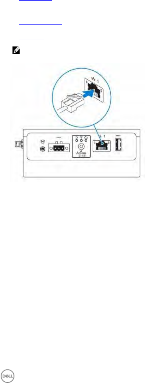
2. Connect an Ethernet cable (optional).
3. Install the antenna(s) depending on the configuration ordered.
13
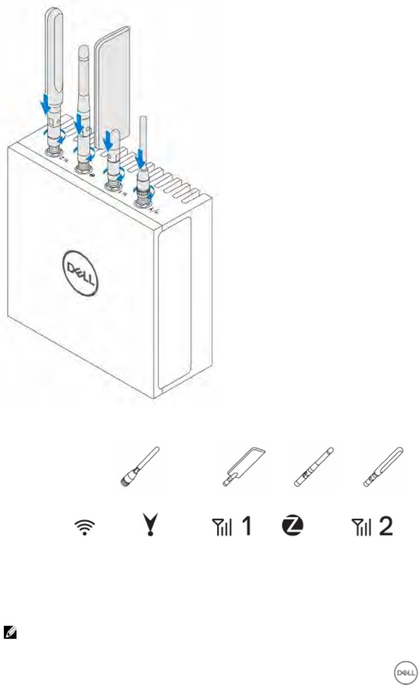
The antenna(s) supported in the Edge Gateway vary depending on the configuration ordered.
Table 6. Antennas supported in Edge Gateway 3000 Series
Antennas
supported
Signals
3000 Yes Not applicable Yes Not applicable Yes
3001 Yes Yes Yes Not applicable Yes
3002 Yes Yes Yes Yes Yes
3003 Yes Yes Yes Not applicable Yes
NOTE: Some of the antenna ports may be capped, depending on the configuration ordered.
14
NOTE: Mobile broadband antenna port two is for LTE only. It does not support 3G.
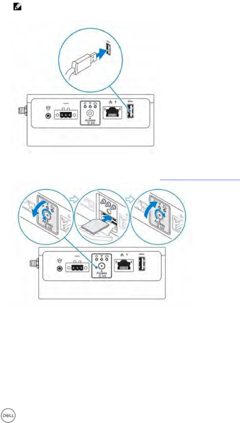
4. Connect a USB cable to connect a display, keyboard, and mouse.
5. Connect all cables to the appropriate I/O ports on the Edge Gateway.
6. Open the micro-SIM/micro-SD card access door.
7. Insert a micro-SIM card into the top micro-SIM card slot and activate your mobile broadband.
8. Insert a micro-SD card into the bottom micro-SD card slot.
15
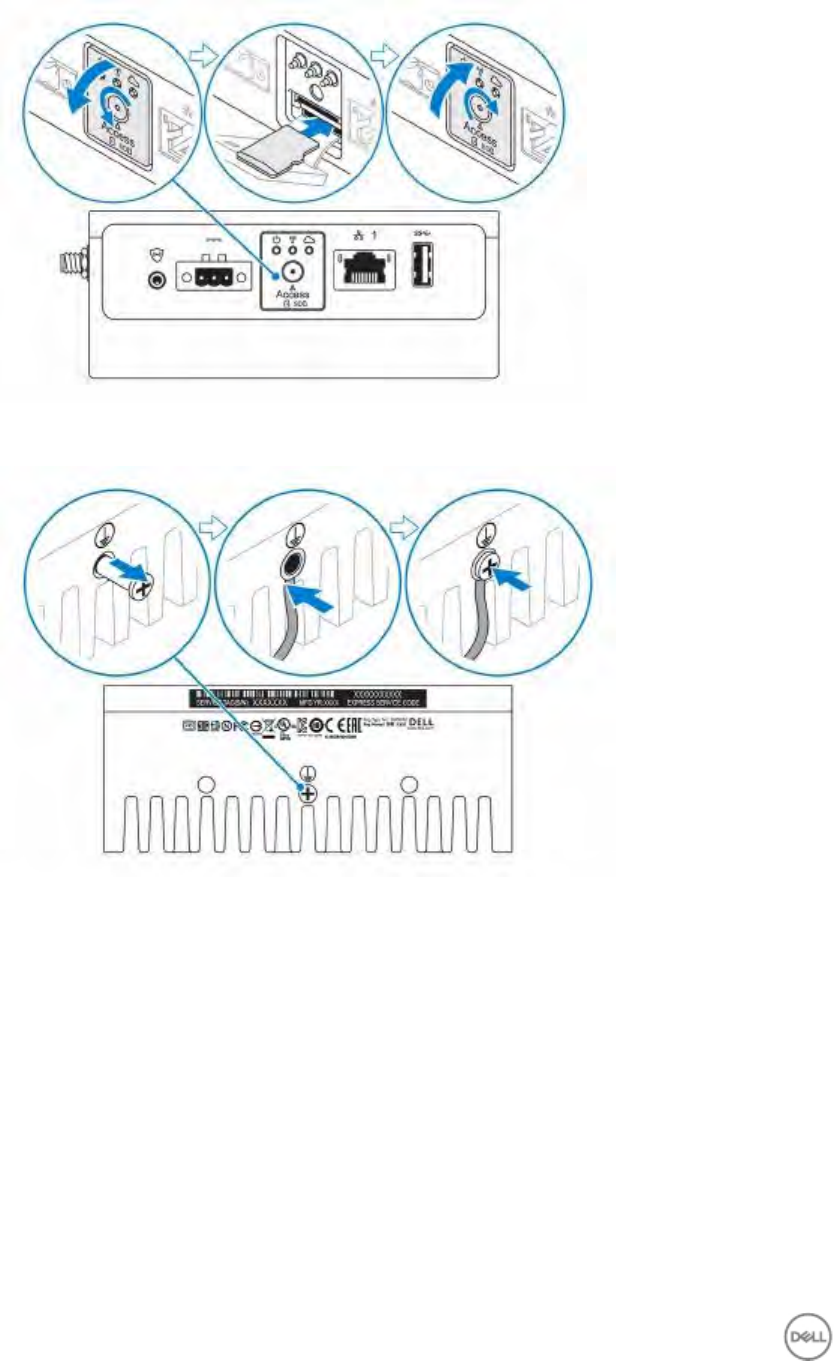
9. Replace the screw and close the access door.
10. Connect a ground cable to the Edge Gateway.
11. Connect the Edge Gateway to one of the following power source.
· DC-IN
16
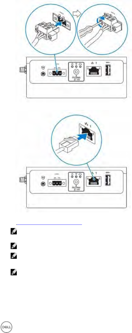
· PoE
12. When setting up the Edge Gateway for the first time, complete the operating system setup. For more information,
see Setting up your operating system.
NOTE: The Edge Gateway is shipped with Windows 10 Enterprise 2016 or Snappy Ubuntu Core Series 16
operating system.
NOTE: On Windows 10 OS, select “Do this later” when prompted to enter the product key.
NOTE: The default user name and password for Snappy Ubuntu Core Series 16 is ubuntu.
13. Configure devices using the RS232/RS422/RS485 ports.
NOTE: After the Edge Gateway setup is complete, reinstall the dust covers on any unused ports.
Activating your mobile broadband
1. Remove the screw to open the micro-SIM card access door.
2. Insert a micro-SIM card into the top micro-SIM card slot.
17
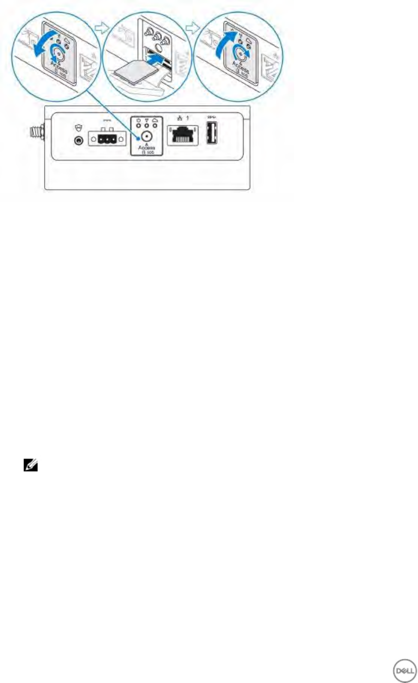
3. Replace the screw and close the micro-SIM card access door.
4. Turn on your Edge Gateway.
5. Connect to a mobile network.
Windows operating system
If the Edge Gateway is shipped with LTE Verizon (DW5815) WWAN or LTE AT&T (DW5815) card:
a. Select the network icon from the taskbar and then click Cellular.
b. Select your Mobile Broadband Carrier → Advanced Options.
c. Make a note of the International Mobile Equipment Identity (IMEI) and the Integrated Circuit Card Identifier
(ICCID).
d. Enter your APN number and other necessary credentials that your WWAN provider requires.
Ubuntu operating system
a. Open the Terminal window.
b. Go to super user mode by entering:$sudo su -
c. Configure the Mobile Broadband connection profile:
#nmcli con add type gsm ifname ttyACM3 con-name <connection name>
apn
<apn>
user
<user name>
password
<password>
d. Connect to the mobile network: #nmcli con up connection name
NOTE: To view the IMEI and ICCID number use the
mmcli
-m
0
--command=+CIMI
command.
To disconnect from the mobile network: #nmcli con downconnection name.
If the Edge Gateway is shipped with LTE AT&T (DW5815) WWAN card:
a. Open the Terminal window.
b. In the terminal type minicom -D /dev/ttyACM0 to open the Minicom terminal.
The Minicom terminal opens with the following text:
Welcome to minicom 2.7
OPTIONS: I18n
Compiled on Dec 17 2015, 16:20:45.
Port /dev/ttyACM0, 21:33:05
Press CTRL-A Z for help on special keys
c. Type the AT+cgdcont command with PDP Context Identifier, “Packet Data Protocol type”, and “Access Point
Name” parameters and press Enter.
Example: at+cgdcont=3,"IPV4V6","broadband".
18

NOTE: If the command runs successfully, the message
OK
appears.
d. Configure the Network Control Mode with the at#ncm command.
Example: at#ncm=1,3.
e. Activate the Packet Data Protocol with the at+cgact command.
Example: at+cgact=1,3.
f. To view the PDP Context Read Dynamic Parameters, that is, bearer_id, apn, ip_addr, subnet_mask, gw_addr,
DNS_prim_addr, DNS_sec_addr, P-CSCF_prim_addr, and P-CSCF_sec_addr parameters, run the at
+cgcontrdp command.
Example: at+cgcontrdp=3
+CGCONTRDP:
,7,"broadband.mnc480.mcc311.gprs","100.106.47.7.255.0.0.0","100.1
6.47.8","198.224.157.135","0.0.0.0","0.0.0.0","0.0.00"
g. Exit the Minicom module.
h. In the Linux terminal configure the connection with the following commands
root@WR-IntelligentDevice:~# ifconfig wwan0 ip_addr netmask subnet_mask
up
root@WR-IntelligentDevice:~# route add default gw gw_addr wwan0
root@WR-IntelligentDevice:~# echo nameserver DNS_prim_addr >>/etc/
resolv.conf
Example:
root@WR-IntelligentDevice:~# ifconfig wwan0 100.106.47.7 netmask
255.0.0.0 up
root@WR-IntelligentDevice:~# route add default gw 100.106.47.8 wwan0
root@WR-IntelligentDevice:~# echo nameserver 198.224.157.135 >>/etc/
resolv.conf
i. Log in to the Minicom module using the minicom -D /dev/ttyACM0 command.
j. Connect to the mobile network using the at+cgdata command.
Example:at+cgdata="M-RAW_IP",3
To disconnect from the mobile network
a. Open the Minicom terminal.
b. Enter the at+cgdata="M-RAW_IP",3 command.
c. Close the Minicom terminal.
d. Enter the root@WR-IntelligentDevice:~# ifconfig wwan0 down command.
Mounting your Edge Gateway
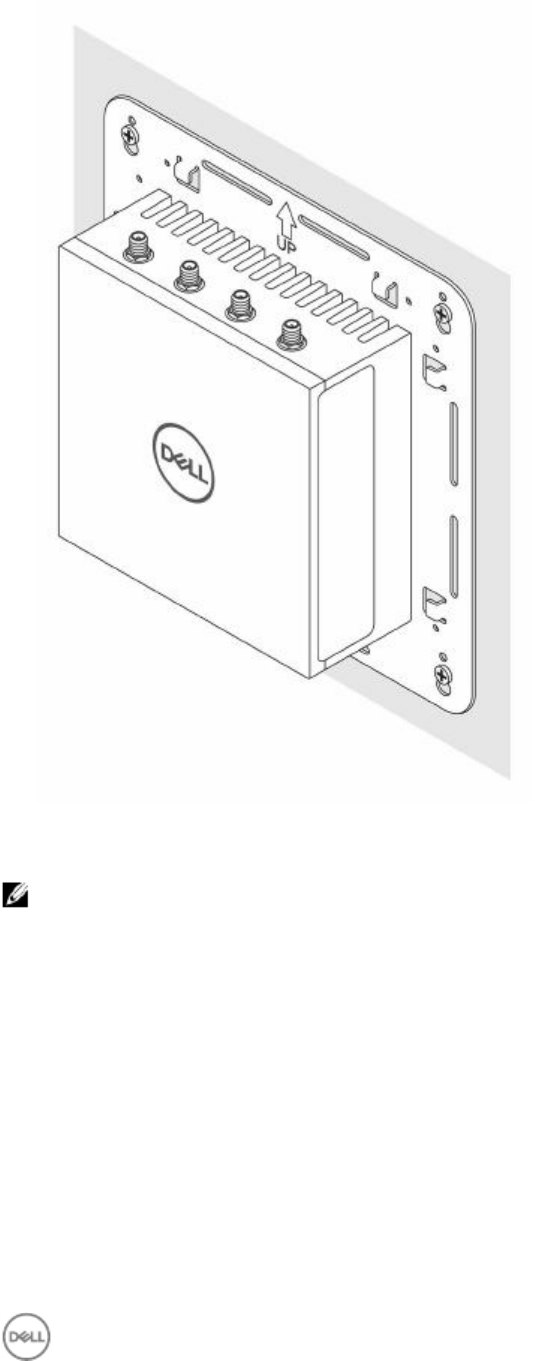
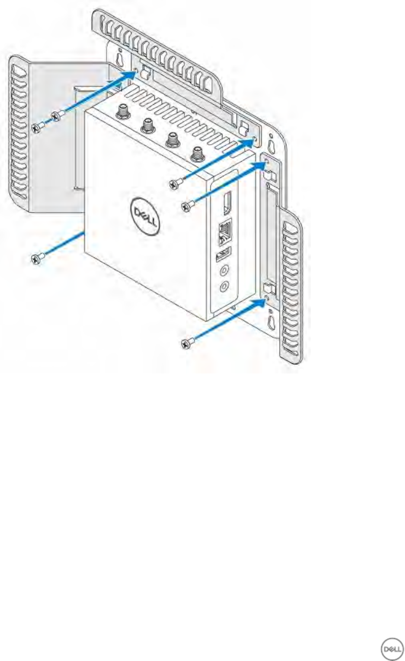
Mounting the Edge Gateway using the standard-mount bracket
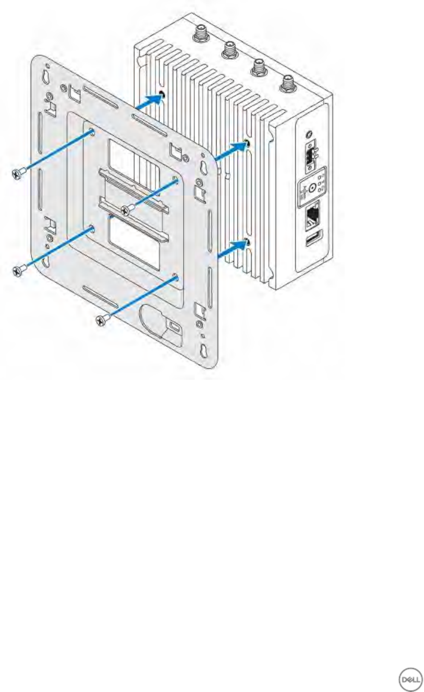
NOTE: The mounting brackets are shipped with only those screws that are required for securing the mounting
brackets to the Edge Gateway.
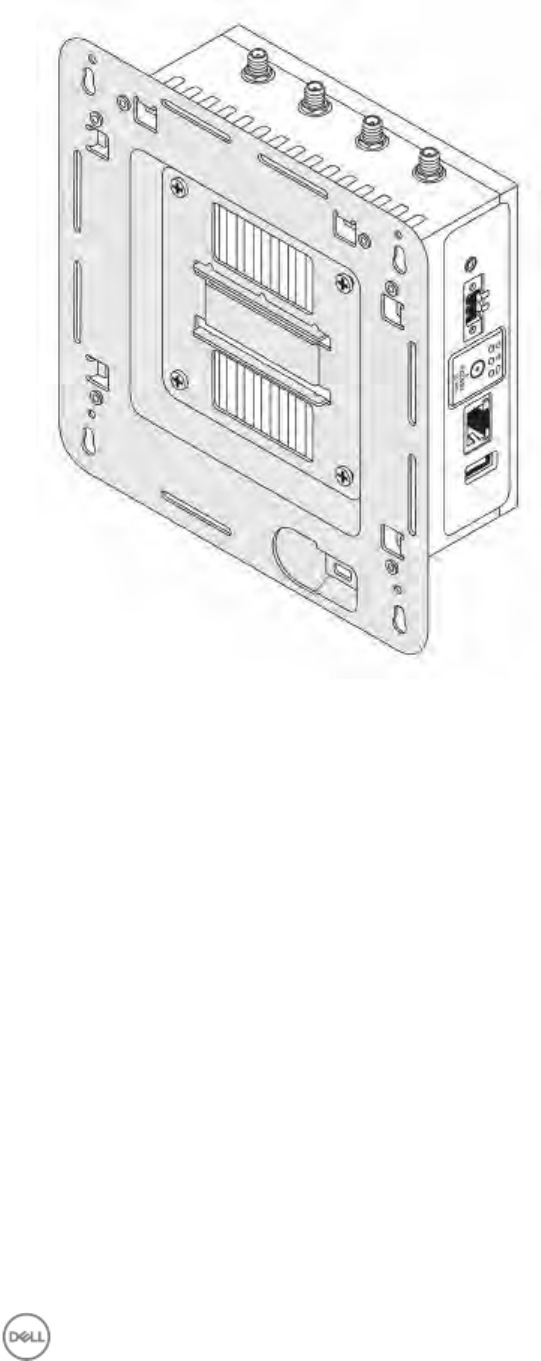
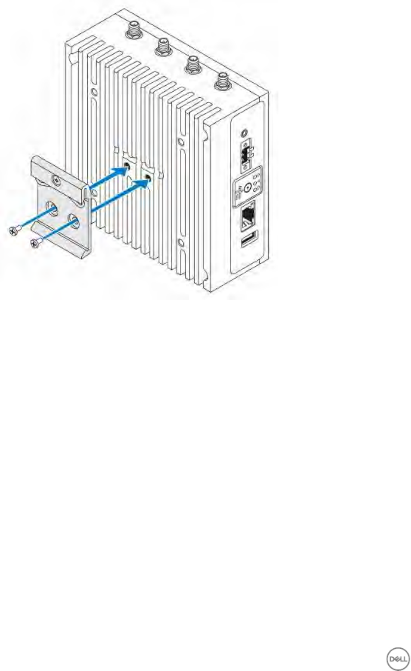
1. Secure the standard-mount bracket to the back of the Edge Gateway by using the four M4x4.5 screws.
NOTE: Torque the screws at 8+/-0.5 kilograms-centimeter (17.64+/-1.1 pounds-inch).
19
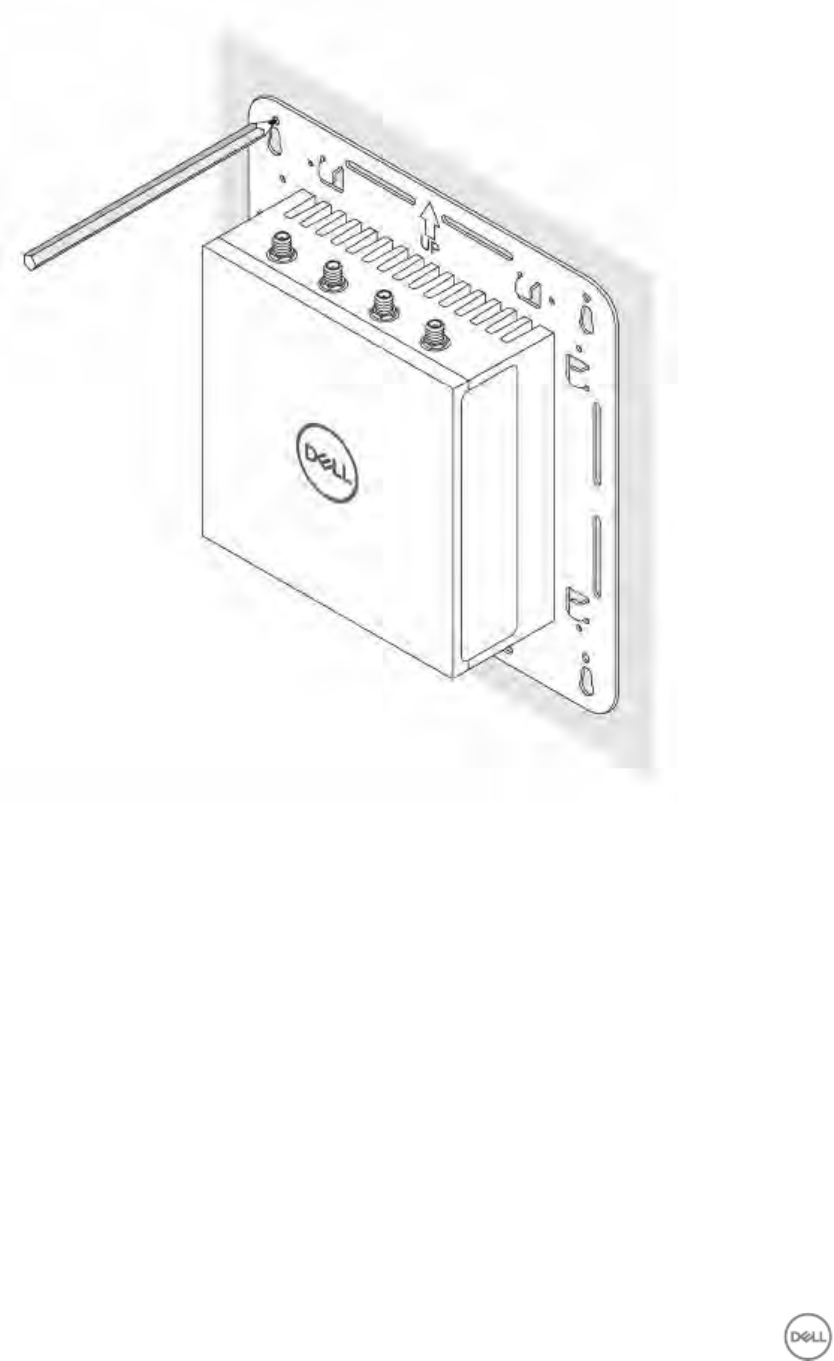
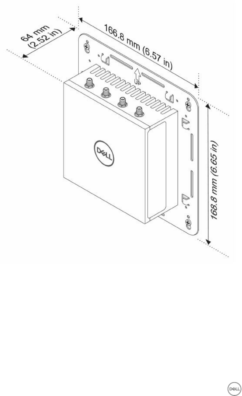
2. Place the Edge Gateway against the wall, and align the holes in the standard-mount bracket with the holes on the
wall. Screw holes on the bracket have a diameter of 3 mm (0.12 in).
20
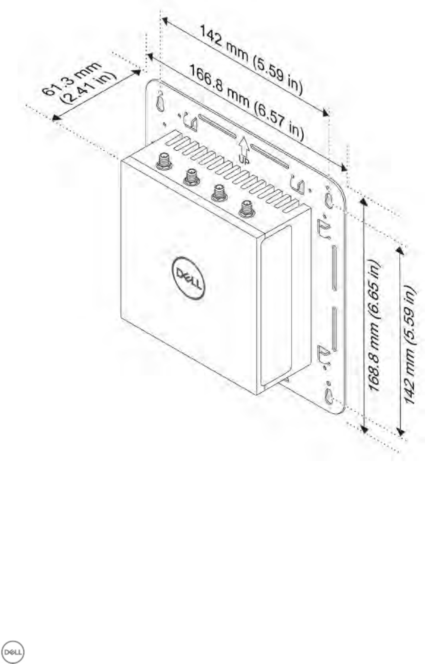
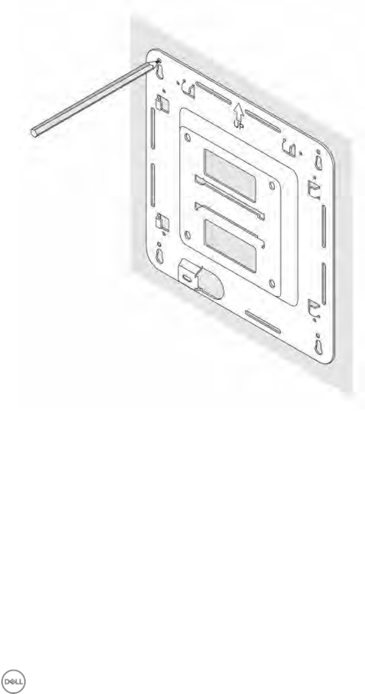
3. Place the standard-mount bracket on the wall, and, using the holes above the screw holes on the bracket, mark the
location to drill the four holes.
21
4. Drill four holes in the wall that correspond to the holes in the standard-mount bracket.
22
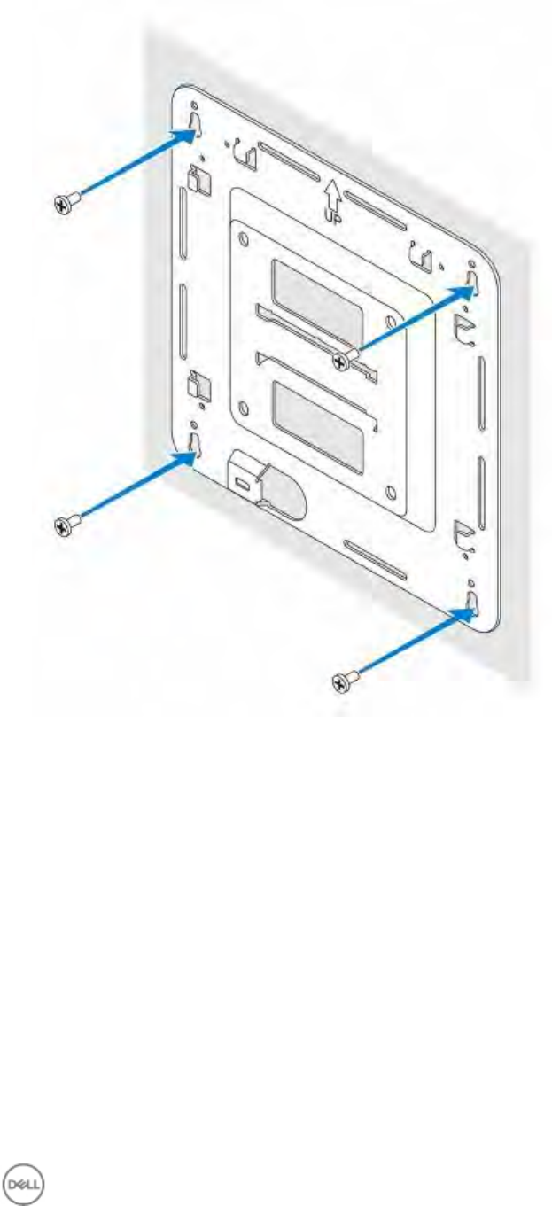
5. Insert and tighten four screws (not supplied) to secure the Edge Gateway to the wall. It is recommended to use
M4x9 screws.
23
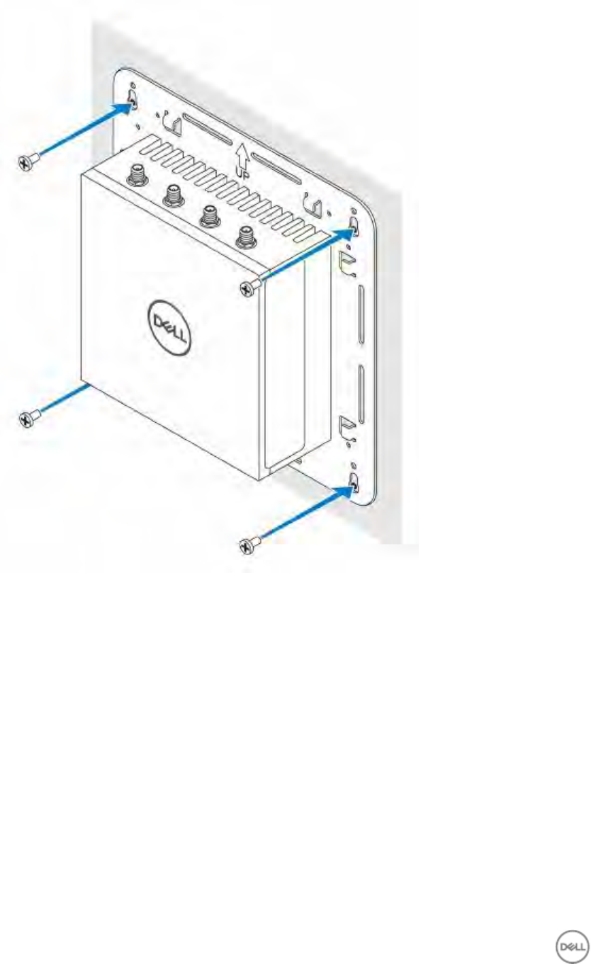
6. Secure the Edge Gateway to the wall.
24
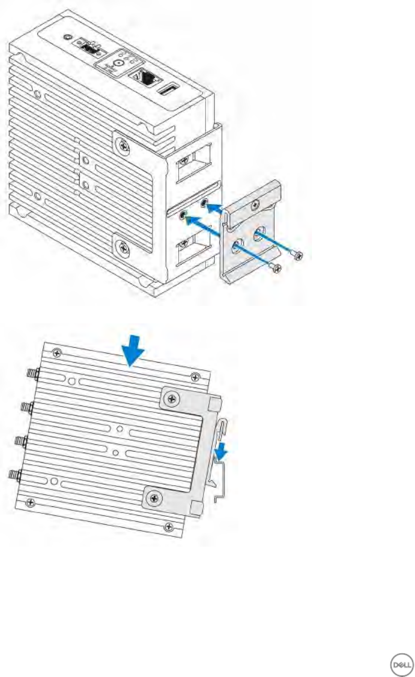
Mounting the Edge Gateway on a DIN rail using the DIN-rail bracket
NOTE: The DIN-rail bracket includes the screws that are required for securing the bracket to the Edge Gateway.
1. Align the screw holes on the DIN-rail bracket with the screw holes at back of the Edge Gateway.
2. Place the two M4x7 screws on the DIN-rail bracket and secure it to the Edge Gateway.
25
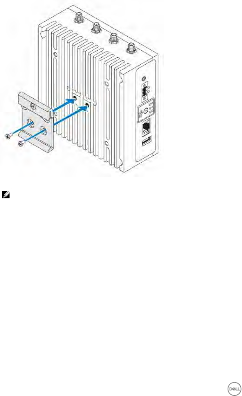
3. Secure the DIN-rail mounting bracket to the Edge Gateway by using the two M4x7 screws provided.
NOTE: Torque the screws at 8+/-0.5 kilograms-centimeter (17.64+/-1.1 pounds-inch) on the DIN-rail mounting
bracket.
26
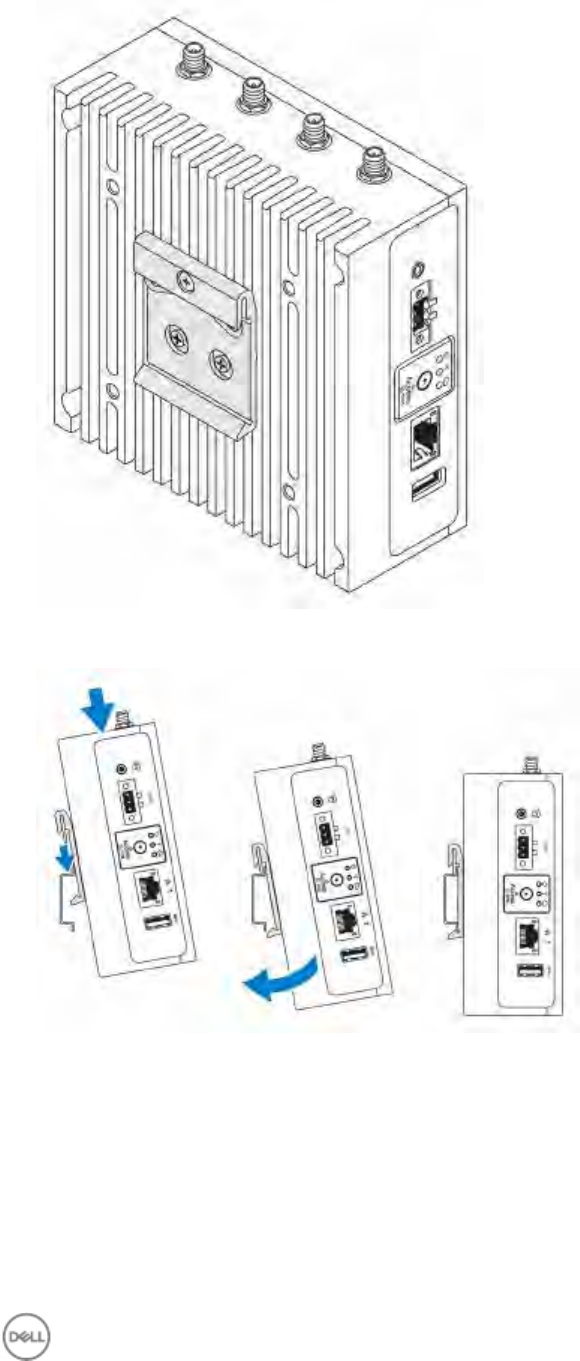
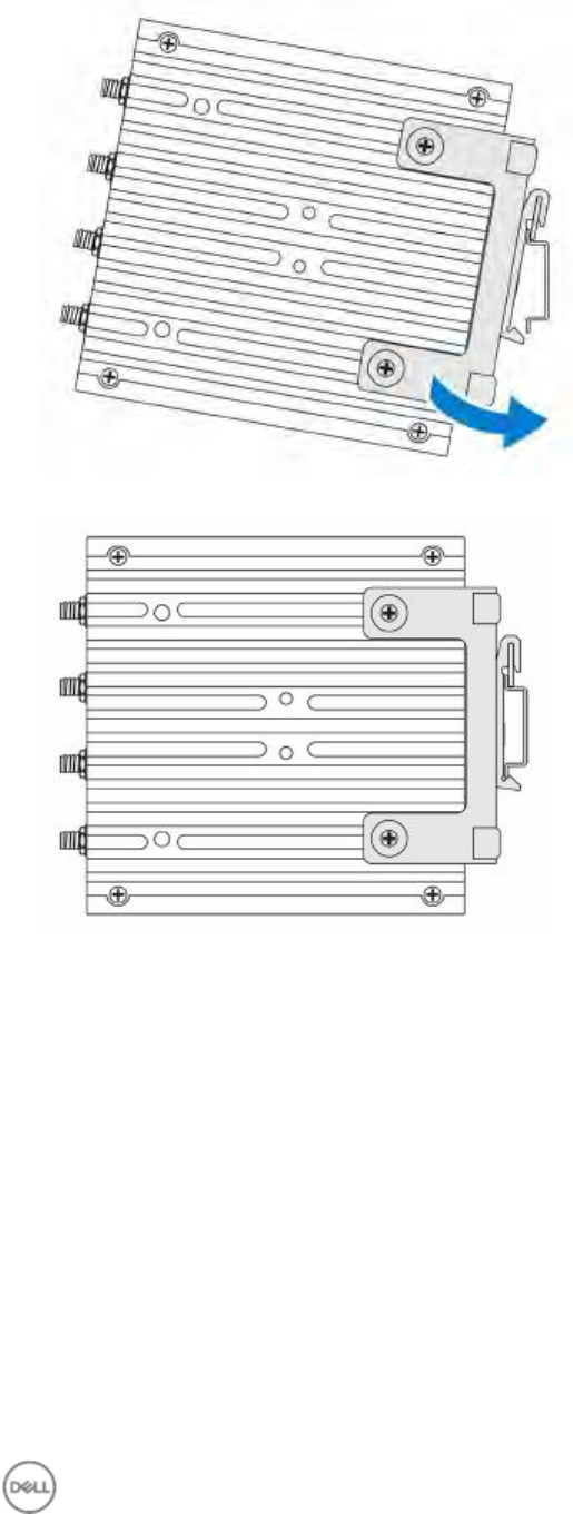
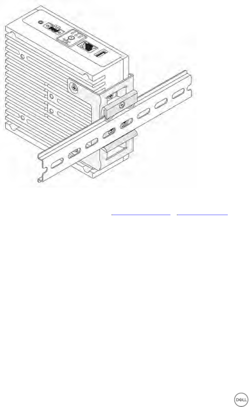
4. Place the Edge Gateway on the DIN rail at an angle, and then pull the Edge Gateway down to compress the springs
at the top of the DIN-rail mounting bracket.
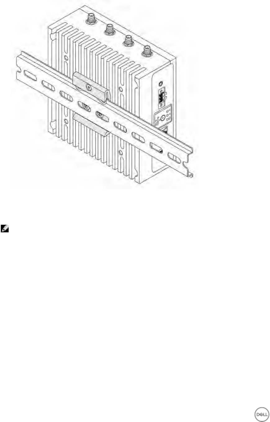
5. Push the Edge Gateway towards the DIN-rail brackets to secure the lower clip of the bracket onto the DIN rail.
27
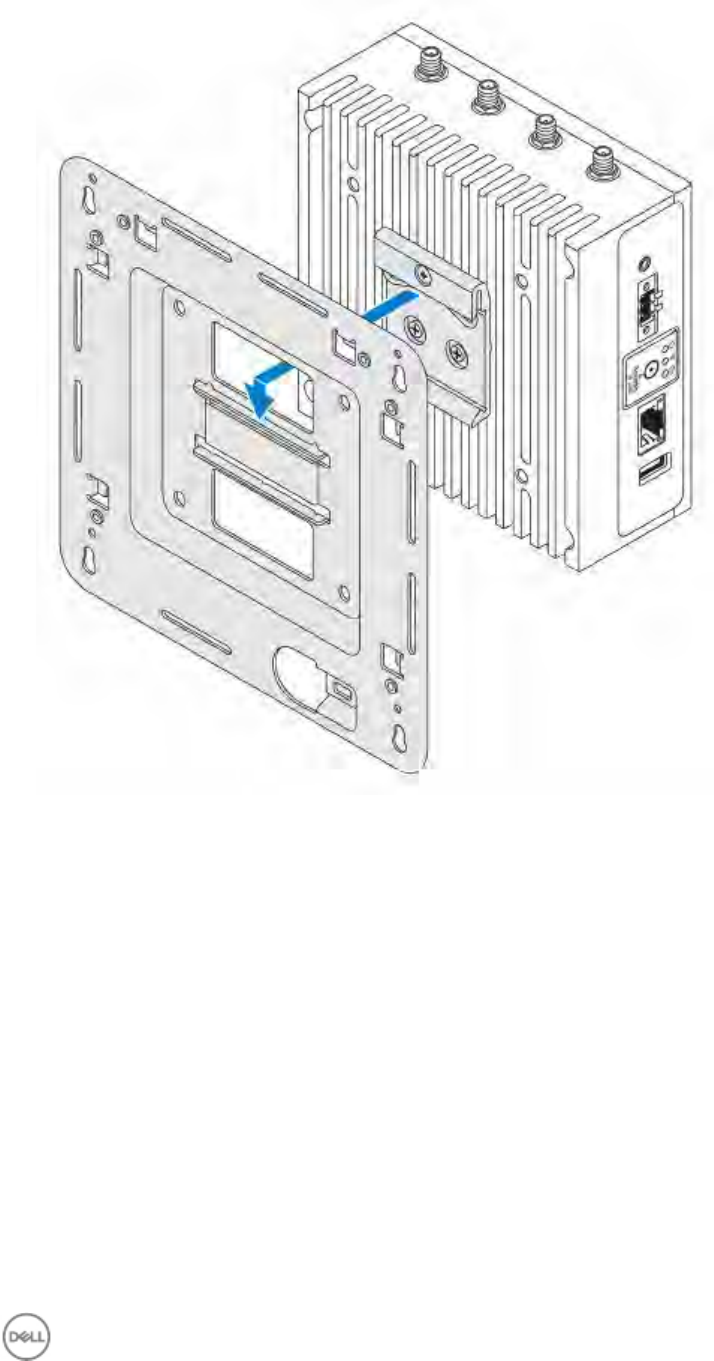
Mounting the Edge Gateway using the quick-mount bracket
The quick-mount bracket is a combination of the standard-mount bracket and DIN-rail bracket.
NOTE: The mounting brackets are shipped with only those screws that are required for securing the mounting
brackets to the Edge Gateway.
1. Place the standard-mount bracket on the wall, and, using the holes above the screw holes on the bracket, mark the
location to drill the four holes.
28
2. Drill four holes in the wall that correspond to the holes in the standard-mount bracket. Screw holes on the bracket
have a diameter of 3 mm (0.12 in).
29
3. Secure the standard-mount bracket to the wall with four screws (not supplied). Screw holes on the bracket have a
diameter of 4.5 mm (0.04 in)
30
4. Align the screw holes on the DIN-rail bracket with the screw holes at the back of the Edge Gateway.
5. Place the two M4x7 screws on the DIN-rail bracket and secure it to the Edge Gateway.
31
6. Mount the Edge Gateway on the standard-mount bracket and secure the Edge Gateway to the standard mount by
pressing the latch.
32
7. Place the Edge Gateway on the standard mount at an angle, and then pull the Edge Gateway down to compress the
springs at the top of the DIN-rail bracket.
33
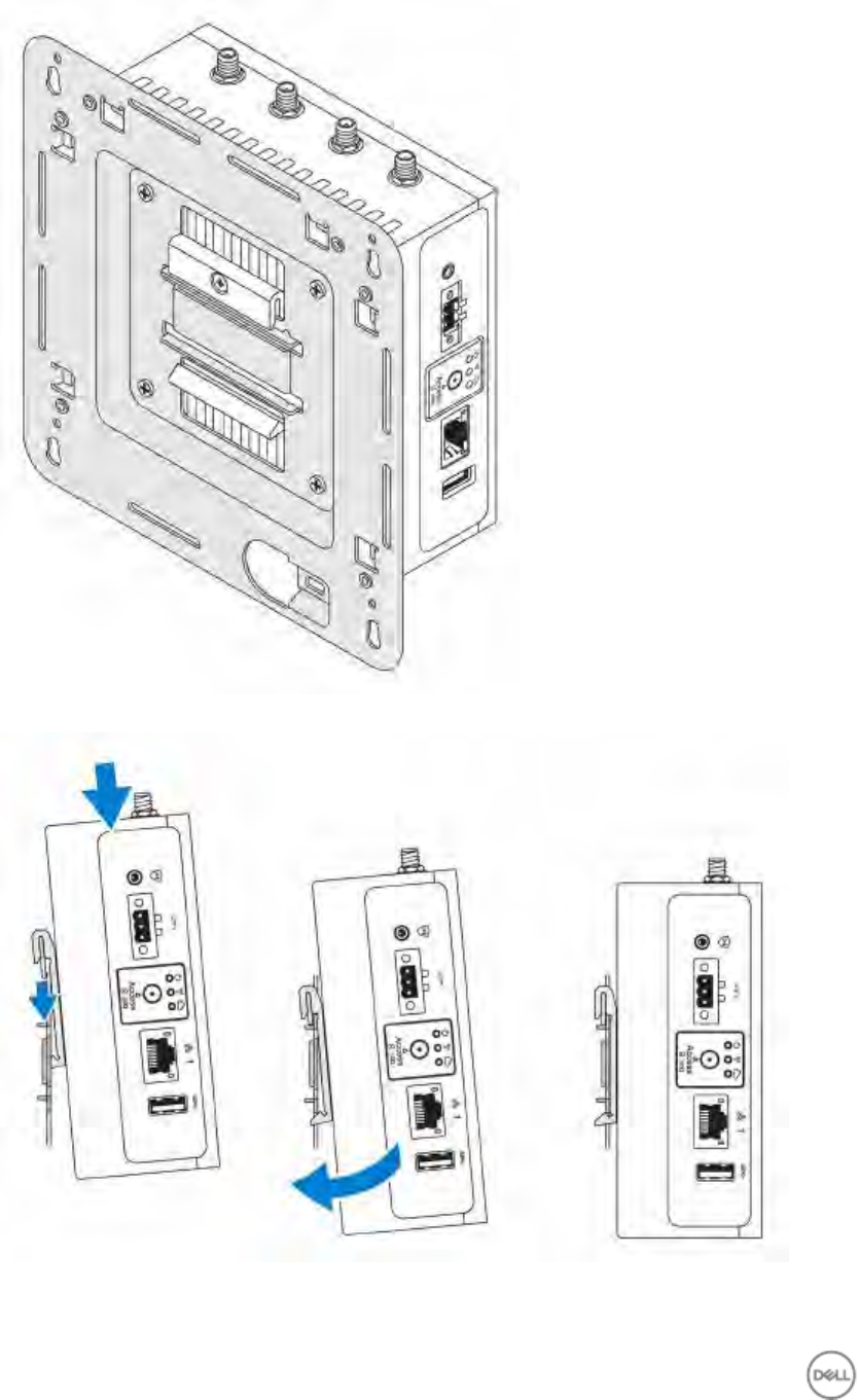
8. Push the Edge Gateway towards the DIN-rail brackets to secure it on the standard-mount bracket.
9. Secure the Edge Gateway to the standard-mount bracket.
34

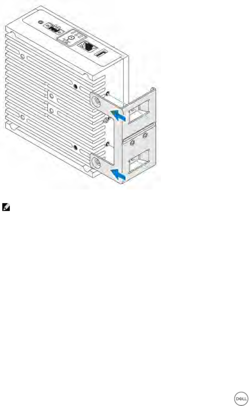
Mounting the Edge Gateway using the perpendicular mount
NOTE: The perpendicular mount is designed for DIN-rail applications only.
1. Align the screw holes on the perpendicular-mount bracket with the screw holes on the Edge Gateway.
35
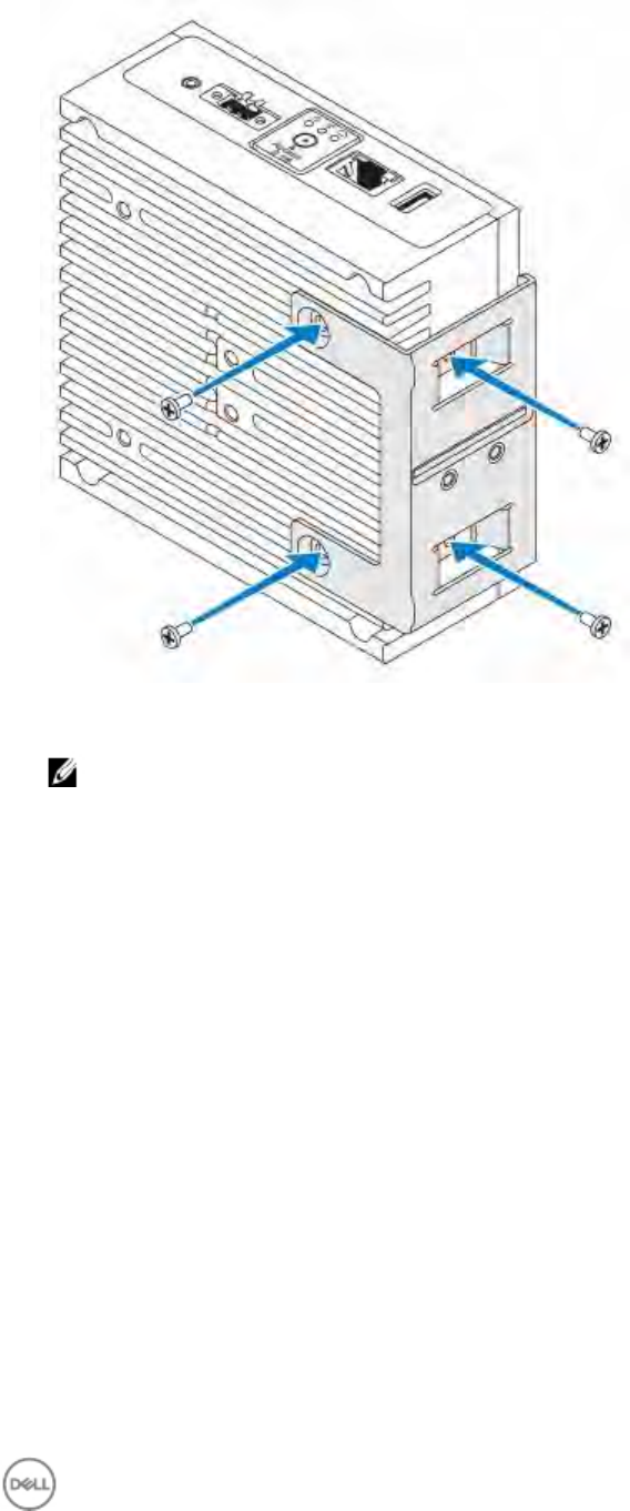
2. Tighten the four M4x7 screws to secure the Edge Gateway to the perpendicular-mount bracket.
NOTE: Torque the screws at 8+/-0.5 kilograms-centimeter (17.64+/-1.1 pounds-inch).
36
3. Align the screw holes on the DIN-rail mount bracket with the screw holes on the perpendicular-mount bracket, and
tighten the two screws.
NOTE: Torque the screws at 8+/-0.5 kilograms-centimeter (17.64+/-1.1 pounds-inch).
37
4. Place the Edge Gateway on the DIN rail at an angle.
5. Pull the Edge Gateway down to compress the springs on the DIN-rail mount brackets and push the Edge Gateway
towards the DIN-rail brackets to secure the bottom of the bracket to the DIN rail.
38
6. Push the Edge Gateway towards the DIN-rail brackets to secure the lower clip of the bracket onto the DIN rail.
7. Secure the Edge Gateway on the DIN rail.
39
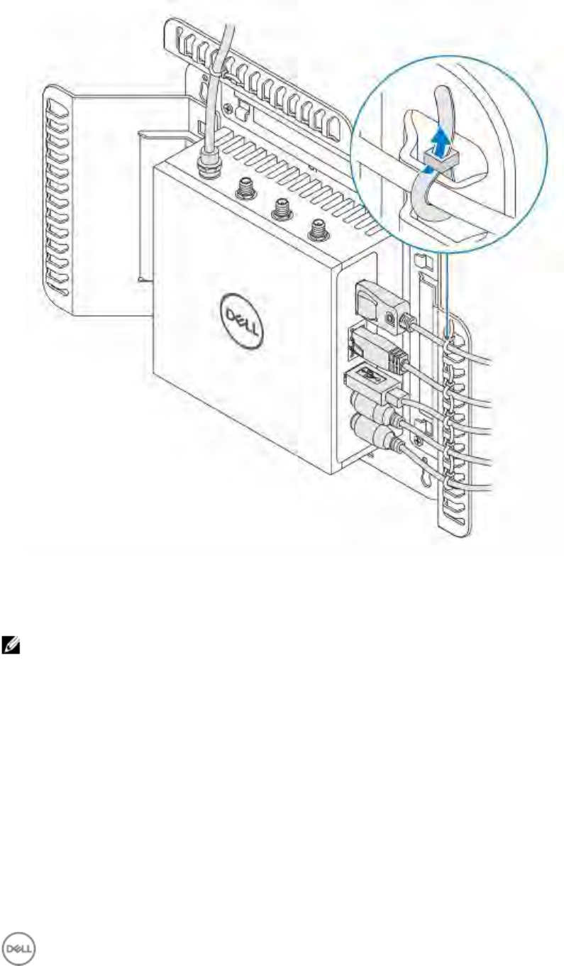
Attaching the cable control bars to the standard-mount bracket
1. Mount the Edge Gateway on the wall using the standard-mount bracket or quick-mount bracket.
2. Place the cable control bar on the mounting bracket and secure it to the notch.
40
3. Align the screw holes on the cable control bar with the screw holes on the mounting bracket.
4. Tighten the six M3 x 3.5 mm screws that secure the cable control bar to the mounting bracket.
NOTE: Torque the screws at 5+/-0.5 kilograms-centimeter (11.02+/-1.1 pounds-inch).
41
5. Connect the cables to the Edge Gateway.
6. Loop the cable lock (not supplied) to secure each cable to the cable control bar.
42
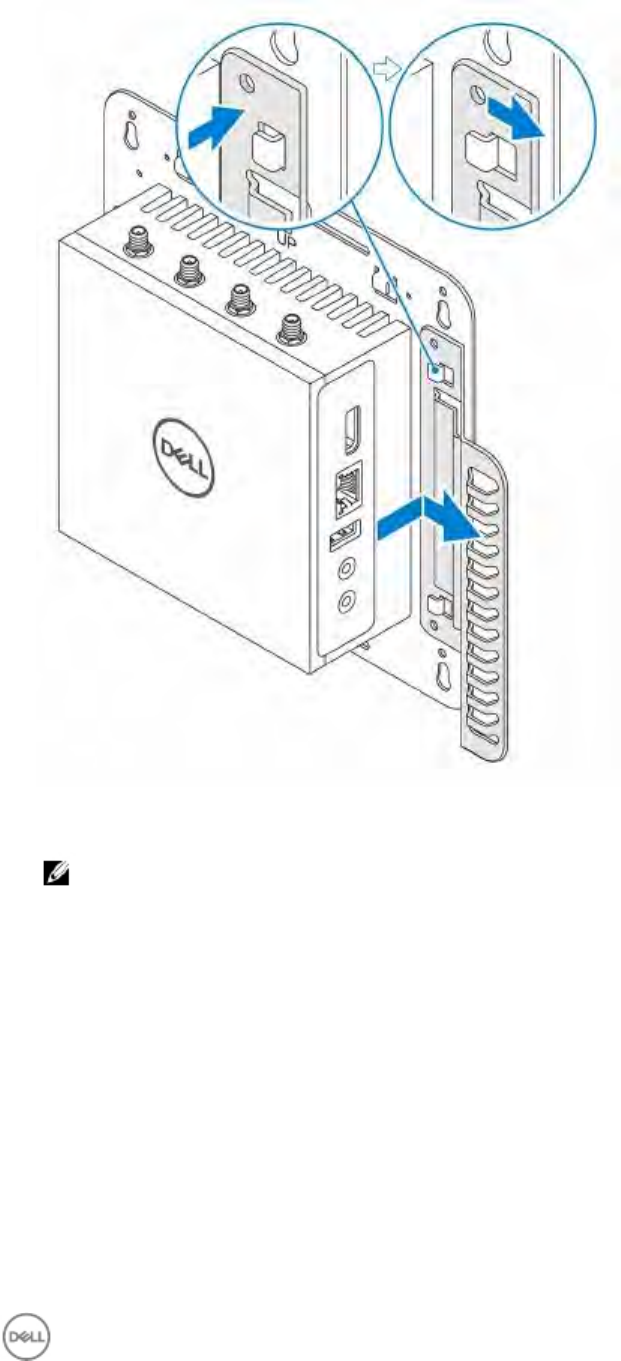
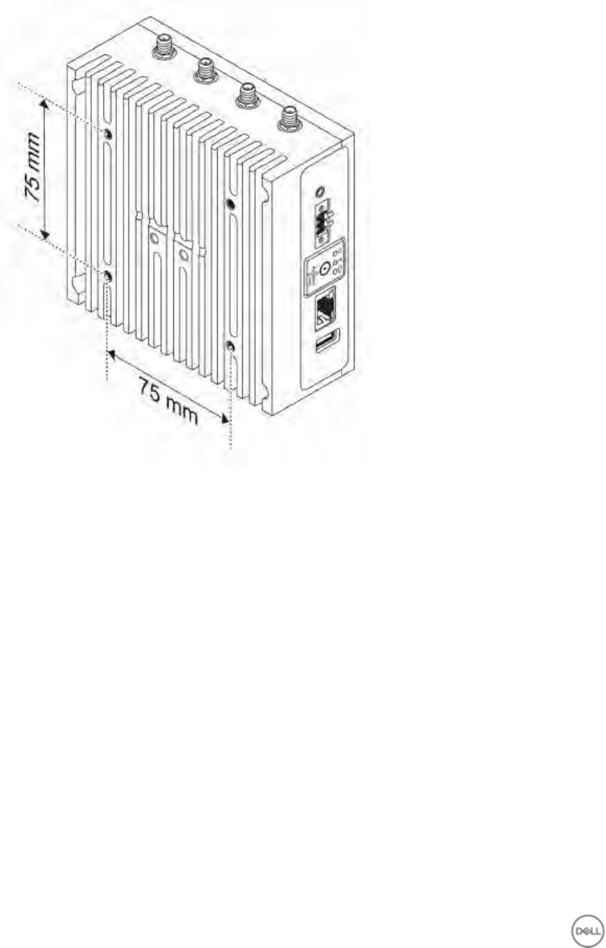
Mounting the Edge Gateway using a VESA mount
The Edge Gateway can be mounted on a standard VESA mount (75 mm x 75 mm).
NOTE: VESA mount option is sold separately.
43
44

Setting
up
your
operating
system
4
WARNING:
To
prevent
operating
system
corruption
from
sudden
power
loss,
use
the
operating
system
to
gracefully
shut
down
the
Edge
Gateway.
The
Edge
Gateway
is
shipped
with
one
of
the
following
operating
systems:
·
Windows
10
IoT
Enterprise
LTSB
2016
·
Ubuntu
Snappy
Series
16
NOTE:
For
more
information
about
the
Windows
operating
system,
see
msdn.microsoft.com.
NOTE:
For
more
information
about
the
Ubuntu
Snappy
Series
16
operating
system,
see
www.ubuntu.com/desktop/
snappy.
Windows
10
Enterprise
LTSB
2016
Overview
The
Edge
Gateway
is
shipped
with
Windows
10
IoT
Enterprise
LTSB
2016.
For
more
information
about
Windows
10
operating
system,
see
https://support.microsoft.com/en-us.
Setting
up
Windows
10
Enterprise
LTSB
2016
1.
Using
the
network
cable,
connect
the
Edge
Gateway
to
your
local
network
with
a
DNS
server,
which
provides
an
IP
address
to
the
Gateway.
2.
Launch
Remote
Desktop
Connection
from
another
client
machine
on
the
same
local
network
and
log
in
using
the
supplied
computer
name,
user
name,
and
password.
3.
After
login,
create
a
unique
user
name
and
password.
Boot
up
and
login
1.
Connect
the
Edge
Gateway
to
a
DHCP
enabled
network
that
provides
IP
addresses
or
directly
to
another
Windows
10
system.
2.
Turn
on
the
Edge
Gateway.
3.
On
the
Host
Machine,
launch
Remote
Desktop
Connection.
4.
Use
the
default
computer
name,
user
name,
and
password
provided
with
your
Edge
Gateway
to
remote
desktop
connection
into
the
system.
5.
Create
a
new
user
name
and
password
with
admin
rights
to
secure
the
system.
6.
Delete
the
default
profile.
Windows
10
IOT
Enterprise
LTSB
2016
basic
functions
BIOS
Update
BIOS
updates
for
the
Edge
Gateway
can
be
downloaded
from
www.dell.com/support.
The
download
includes
an
executable
that
may
be
ran
from
the
local
machine.
45

Watchdog Timer
The Watchdog Timer for Windows 10 IoT Enterprise LTSB 2016 is controlled through the BIOS setting. Enter the BIOS
during boot by pressing F2. The Watchdog Timer is enabled and disabled under the BIOS setting Watchdog Timer.
TPM Support
Windows 10 IoT Enterprise LTSB 2016 supports TPM 2.0. For more information about TPM resources, see
technet.microsoft.com/en-us/library/cc749022(v=ws.10).aspx.
System Shutdown and Restart
Click the Start Icon and then press Power then Restart or Shutdown the Edge Gateway.
LAN/WLAN Network configuration
Click the Start Icon and then type Settings and open the Settings window. Select Network & Internet from the
settings menu.
Bluetooth configuration
Click the Start Icon and then type Settings and open the Settings window. Select Devices from the settings menu
and then select Bluetooth from the menu on the left panel.
DW5815 Network configuration
Follow the Service Manual to install and configure the WWAN module and the corresponding carrier SIM card for the
system. After the WWAN module and the SIM cards are installed:
1. Click the Start Icon and then type Settings and open the Settings window.
2. Select Network & Internet from the Settings menu.
3. Locate the WWAN connection in the Wi-Fi section and select the entry to connect and disconnect from the
WWAN adapter.
Snappy Ubuntu Core Series 16
Overview
Snappy Ubuntu Core Series 16 is a Linux OS distribution that is an entirely new mechanism for managing a system and
its applications. For more information on Snappy Ubuntu Core Series 16 OS, see
· www.ubuntu.com/cloud/snappy
· www.ubuntu.com/internet-of-things
Pre-requisites
Infrastructure
An active connection to the internet is needed to update the Snappy Ubuntu Core Series 16 operating system as well as
applications (snaps)
Prior knowledge
· Familiarity with Unix\Linux commands
· Knowledge of how to use the serial communication protocol
· Knowledge of how to use a terminal emulator (for example; PuTTY)
· Knowledge of your network settings (proxy URL, ports, name servers, and so on)
Boot up and log in
NOTE: The Snappy Ubuntu Core Series 16 operating system has no graphical user interface
Turn on the Edge Gateway and when prompted log in to the OS using the default credentials. The default user name and
password for Ubuntu Core Series 16 is admin.
46

NOTE: The user name and password are both lowercase.
For example;
Ubuntu 16.04 localhost.localdomain tty1
localhost login: ubuntu
Password: ubuntu
Press Enter, the following text is displayed:
Ubuntu 16.04 localhost.localdomain tty1
localhost login: ubuntu
Password
Last login: Mon Nov 2 16:47:43 UTC 2015 on tty1
Welcome to Ubuntu Core Series 16, a transactionally updated Ubuntu
* See http://ubuntu.com/snappy
It’s a brave new world her in snappy Ubuntu Core! This machine
does not use apt-get or deb packages. Please see ‘snap –help’
for app installation and transactional updates
(plano)ubuntu@localhost:~$
Updating operating system and applications
After enabling the network connections, and connecting to the internet, it is recommended to have the latest OS
components and applications installed. To update Snappy Ubuntu Core Series 16, run the
(plano)ubuntu@localhost:~$ sudo snappy update command.
Viewing operating system and application versions
Running command,
(plano)ubuntu@localhost:~$ sudo uname –a
returns
Linux ubuntu.localdomain 3.19.0-47-generic #53-Ubuntu SMP Mon Jan 18 14:02:48
UTC 2016 x86_64 x86_64 x86_64 GNU/Linux
Running command,
(plano)ubuntu@localhost:~$ sudo snap info
returns
Linux power5000.localdomain 3.19.0-47-generic #53-Ubuntu SMP Mon Jan 18
14:02:48 UTC 2016 x86_64 x86_64 x86_64 GNU/Linux
Running command,
(plano)ubuntu@localhost:~$ snap list -v
returns
Name Date Version
Developer
ubuntu-core 2015-10-13 7 ubuntu
bluez 2015-10-20 5.34-2
canonical*
network-namager 2015-10-20 0.2 canonical*
plano-uefi-fw-tools 2015-10-20 0.5 canonical*
webdm 2015-10-20 0.9.2
canonical*
plano-webdm 2015-10-20 1.7
canonical*
47

NOTE: Check if a newer version of the software is available. For more information on checking for updates, see
Updating operating system and applications.
Useful commands
To access the built-in help, run the (plano)ubuntu@localhost:~$ snap --help command.
To see the system attributes, run the (plano)ubuntu@localhost:~$ snap info command.
To see a list of all the snaps that are currently installed, run the (plano)ubuntu@localhost:~$ snap list
command.
To see a list of all the snaps that you can install on the system, run the (plano)ubuntu@localhost:~$ snap
search command.
To see a list of service commands that are available, run the (plano)ubuntu@localhost:~$ snap service
help command.
To see the service status, run the (plano)ubuntu@localhost:~$ snap service status command.
Updating the system name
1. To change the system name, make a folder Read\Write and then make changes to two files:
· /etc/hosts
· /etc/hostname
2. Make a backup of the file names.
(plano)ubuntu@localhost:~$ sudo cp /etc/hosts /etc/hosts.old
(plano)ubuntu@localhost:~$ sudo cp /etc/hostname /etc/hostname.old
3. Edit the hosts file.
(plano)ubuntu@localhost:~$ sudo vi /etc/hosts
For example;
127.0.0.1 localhost.localdomain localhost
127.0.1.1 <newname>.localdomain <newname>
4. Edit the hostname file.
(plano)ubuntu@localhost:~$ sudo vi /etc/hostname
5. Reboot the system to allow the changes to take effect.
(plano)ubuntu@localhost:~$ sudo shutdown –r 0
Changing the time zone
When the system arrives from the factory the OS will usually be set to UTC time zone. To change the time zone to your
location you will need to run the command:
(plano)ubuntu@localhost:~$ sudo mount –o remount,r/
(plano)ubuntu@localhost:~$ sudo dpkg-reconfigure tzdata
Follow the menus the program provides to select the correct time zone. After you have set the time zone you will need to
reboot the computer.
NOTE: Ubuntu Snappy runs a time sync daemon. Changing the time will require a special utility to change the time.
On the desktop version of the Ubuntu OS, read the man file for the utility
timedatectl
. This man file explains
how to change the time manually.
Enabling console login via serial
To enable console login via serial (ttyS6) you will need to edit the /boot/grub/grub.cfg file, save your changes, and reboot
the gateway.
(plano)ubuntu@localhost:~$ sudo vi /boot/grub/grub.d
48

Got to line number 42 and change the first console-ttyS0 so that it points to ttyS6 console=ttyS6. Now the line in the
file should look like this:
42 set cmdline="root=LABEL=$label ro init=/lib/systemd/systemd console=ttyS6
console=tty1 panic=-1"
Save the file, and reboot the Edge Gateway. Upon reboot you will be able to see the Operating System boot process as
well as you will be able to login to the gateway via the console screen that is using the serial port on the front of the
Edge Gateway.
Network Communication Interfaces
The Edge Gateway 3000 series comes with two Ethernet connections, one 802.11b/g/n wireless network connection, and
one Bluetooth network connection.
Ethernet (Port 1, eth0)
Assuming that you have an internet enabled Ethernet cable plugged into Port1, your screen should be similar to the one
below after running the ifconfig command. If the Wi-Fi and Bluetooth have not been configured you will not see
them present in the network device list.
(plano)ubuntu@localhost:~$ ifconfig
After running the ifconfig command:
eth0 Link encap:Ethernet HWaddr 74:e6:e2:e3:0f:12
inet addr:192.168.28.216 Bcast:192.168.28.255 Mask:255.255.255.0
inet6 addr: fe80::76e6:e2ff:fee3:f12/64 Scope:Link
UP BROADCAST RUNNING MULTICAST MTU:1500 Metric:1
RX packets:11 errors:0 dropped:0 overruns:0 frame:0
TX packets:19 errors:0 dropped:0 overruns:0 carrier:0
Collisions:0 txqueuelen:1000
RX bytes:1740 (1.7 KB) TX bytes:2004 (3.0 KB)
lo Link encap:Local Loopback
inet addr:127.0.0.1 Mask:255.0.0.0
inet6 addr: ::1/128 Scope:Host
UP LOOPBACK RUNNING MTU:65536 Metric:1
RX packets:160 errors:0 dropped:0 overruns:0 frame:0
TX packets:160 errors:0 dropped:0 overruns:0 carrier:0
Collisions:0 txqueuelen:1000
RX bytes:13920 (13.9 KB) TX bytes:13920 (13.9 KB)
(plano)ubuntu@localhost:~$
Wi-fi (mlan0)
You will use the Network Manager TUI graphical manager to add/remove wireless networks which can be found in the /
apps/bin folder.
(plano)ubuntu@localhost:~$ cd /apps/bin
(plano)ubuntu@localhost:~$ cd /apps/bin
(plano)ubuntu@localhost:/apps/bin$
(plano)ubuntu@localhost:/apps/bin$ sudo ./nmtui
After you add a new Wi-Fi connection, return to the command prompt and run the ifconfig command again. You
should see that your Wi-Fi network device has connected to the access point you just added and it has obtained an ip-
address.
Bluetooth
Use the supplied command line utility to add/remove/communicate with Bluetooth devices. The command line utility can
be found in the /apps/bin folder.
Before setting up the Bluetooth connection, a Bluetooth device that is discoverable and can discover other devices (for
example a cell phone)– is called device_2.
49

1. Access the command line utility.
(plano)ubuntu@localhost:~$ sudo ./apps/bin/bluetoothctl
2. To see what Bluetooth devices are installed on the system under test run the [bluetoothclt]# list
command.
3. To view the status of the installed Bluetooth device, run the [bluetoothclt]# show command.
4. If the installed Bluetooth device is not powered on, run the [bluetoothclt]# power on command.
5. If the installed Bluetooth device is not discoverable, run the [bluetoothclt]# discoverable on
command.
6. If the installed Bluetooth device is not pair-able, run the [bluetoothclt]# pairable on command.
7. Scan for new devices by running the [bluetoothclt]# scan on command.
NOTE: Make sure that device_2 is set to discoverable and ready to pair with the Edge Gateway.
If required, acknowledge or approve the Edge Gateway connection request to device_2. If device_2 is found it
should display its device ID on the screen under the last command issued. For example, if pairing with a phone, the
ID will look similar to <phone name>: XX:XX:XX:XX:XX:XX
8. Turn the device scanning off by running the [bluetoothclt]# scan off command.
9. Turn paring mode off by running the [bluetoothclt]# scan off command.
10. Turn discovery off by running the [bluetoothclt]# discoverable off command.
11. Turn the power to the device off by running the [bluetoothclt]# power off command.
12. Exit the program by running the [bluetoothclt]# quit command.
Software enabled Access Point (SoftAP)
NOTE: This feature depends on Wi-Fi card and associated driver support to act as a wireless access point.
To install SoftAP:
1. Login to snappy, make sure the device is connected to internet.
2. Run the #sudo snap seach softap command to find the application from Snappy Store.
3. Run the #sudo snap install wifi-ap command to install the app.
After snap is installed make sure that your system has the following snaps, with the minimum version number listed,
installed on your system.
· network-manager 0.8 canonical
· sw-access-point 1.0 canonical
After the snap installation the service should be running as default configuration:
SSID: Ubuntu
Open-authentication
802.11n 2.4GHz (G mode)
IP Address: 10.0.60.1
DHCP Range: 10.0.60.3-20
DNS server: 10.0.60.1
Gateway: 10.0.60.1
Modes of operation - Access Point
The default mode of operation of this snap is Access Point (AP). To connect to the AP, a client simply needs to discover
a network following the specifications defined above. The AP is configured to accept and forward all network traffic as
a slave access point would on any WiFi network. The AP can be configured to change its common settings such as
SSID, hardware mode and security. To do this, the /var/lib/apps/swaccesspoint.canonical/current/hostapd.conf file must
be edited.
NOTE: This file corresponds to the hostapd configuration file from Linux and it’s manual pages can be found online
at: https://w1.fi/cgit/hostap/plain/hostapd/hostapd.conf
50

Default provided configuration is:
interface=uap0
driver=nl80211
ssid=Ubuntu
hw_mode=g
channel=6
macaddr_acl=0
auth_algs=1
ignore_broadcast_ssid=0
wmm_enabled=1
ieee80211n=1
WPAPSK
Example:
interface=uap0
driver=nl80211
ssid=Ubuntu
hw_mode=g
channel=6
macaddr_acl=0
auth_algs=1
ignore_broadcast_ssid=0
wpa=2
wpa_passphrase=UbuntuAP
wpa_key_mgmt=WPAPSK
wpa_pairwise=TKIP
rsn_pairwise=CCMP
wmm_enabled=1
ieee80211n=1
To reload configuration and restart the hotspot, run the $ sudo snap service restart swaccesspoint
command.
In the case of a network being manually configured via ifupdown, the software access point will not start as it would
otherwise clash in the wireless namespace. The same is not true of Network Manager configured networks, those don’t
cause the AP to stop and depending on the setup can work at the same time.
In case of any issues, please bring down the mlan0 connections setup by Network Manager and allow configuration
through the provide web interface.
Modes of operation - Client Network Selection
The second mode of operation is that of using the AP to leverage a default interface for finding and connecting to other
local wireless networks. This is the use case of an out-of-the-box experience where the AP is solely being used for
initial configuration.
If you connect a client to the access point and point the browser to http://10.0.60.1:8888 you can find a web interface.
Through this web interface, you can scan for nearby networks of the device and configure its connection to an SSID of
your choice. By doing this the access point functionality is disabled and the device goes into client/managed mode.
Upon selection of a network and introduction of the password, the device will configure the network and reboot. Note
that the client device on which the browser was running should now join the same network to connect to Snappy
Ubuntu Core Series 16 system.
Additional Communication Interfaces
CANbus
The device used in the Edge Gateway 3000 is the Microchip PIC32MX530F128H microcontroller. This feature is only
supported if hardware module presented, OS provides the capability of mutual communication between user space
application and physical module. If there is a specific CAN bus programming requirement of user mode application,
contact the hardware provider of that module for API documentation.
The CANbus LEDs default state is OFF, and will only be ON when data is being transmitted.
Ready to use software to control or manipulate the device is not available from Dell. The information listed below is
provide by the device’s manufacturer. Dell does not have any specifications regarding the function of F/W design of
51

CANBus and PIC GPIO controller. Dell is providing basic ‘bit-banging’ & data I/O transfer capability, the rest is
determined by an ISV’s or SI’s application. Additionally ISV’s or SI’s could acquire other software packages from
Microchip, if available, and download them to the controller.
Microsoft Windows
If you are using a Microsoft Windows operating system the VID and PID will show as HID\VID_04D8&PID_003F or
HID\VID_04D8&PID_003C.
Snappy Ubuntu Core 16
To verify that the hardware is installed when running Snappy, run the #dmesg | grep –i microchip command.
Serial
The RS232 and RS422\485 LEDs default state is OFF, and will only be ONwhen data is being transmitted. The device
nodes are ordered by port position starting with the left most port being RS232.
Number Port Type Connector Device Node Mem Space IRQ
1 RS232 DB9 /dev/ttyS6 2D0h IRQ 7
2 RS422_485 Phoenix 5 pin /dev/ttyS4 3E0h IRQ 10
3 RS485 Phoenix 3 pin /dev/ttyS5 2E0h IRQ 11
4 RS485 Phoenix 3 pin /dev/ttyS2 3E8h IRQ 10
RS232
Ready to use software to control or manipulate devices are not available from Dell.
RS422\RS485
Ready to use software to control or manipulate the device is not available from Dell.
The transceiver for RS485\RS422 SP339EER as well as dedicated RS485 transceivers XR3088XID share ESD protection
specs of: “All transmitter outputs and receiver inputs feature robust electrostatic discharge (ESD) protection to ±15kV
IEC-61000-4-2 Air Gap, ±8kV IEC-61000-4-2 Contact, and ±15kV Human Body Model (HBM)”
Zigbee
The device used in the Edge Gateway is the Silicon Labs ETRX3587HR-D1. This feature is only supported if hardware
module presented, OS provides the capability of mutual communication between user space application and physical
module. If there is a specific Zigbee programming requirement of user mode application, contact the hardware provider
of that module for API documentation.
Security
Trusted Platform Module (TPM)
TPM is supported on the Dell Edge Gateway 3000 Series. This setting is configurable in the BIOS and manageable in the
OS.
Watchdog Timer
WDT is recommended to be default enabled to active the fail-safe circuitry, Snappy is a Watchdog Timer compatible OS
provides capability to detect and recover system from malfunctions, the design reacts by itself when system hangs
unexpected crash.
Cloud Light
NOTE: If you are using Microsoft Window 10 Enterprise LTSB the cloud light will not function. This is due to a
Microsoft driver issue that was not resolved by the time the OS was released.
One unique feature of the Edge Gateway 3000 series is the Cloud Light. The Cloud Light allows you to visually inspect the
operational status of the Edge Gateway just by looking at the display light on the left side panel of the system.
To enable this feature all that you need to do is expose and program a GPIO register on the system.
52

1. Expose the GPIO register.
(plano)ubuntu@localhost:~$ sudo sh -c 'echo 346 > /sys/class/gpio/export;
sleep 2; echo out > /sys/class/gpio/gpio346/direction'
2. Command to turn on the LED.
(plano)ubuntu@localhost:~$ sudo sh -c 'echo 1 > /sys/class/gpio/gpio346/
value'
3. Command to turn off the LED.
(plano)ubuntu@localhost:~$ sudo sh -c 'echo 0 > /sys/class/gpio/gpio346/
value'
Restoring Snappy Ubuntu Core Series 16
CAUTION: Following the steps deletes all the data on your system.
The following steps refer to different methods through which the Snappy Ubuntu Core Series 16 operating system can be
restored to the factory image.
External storage
On supported platforms, you can download the factory image from www.dell.com to restore your Edge Gateway by
external media kit. For more information, see www.dell.com/support/article/us/en/19/SLN301761.
Factory OS recovery image
You can restore Snappy Ubuntu Core Series 16 on the Edge Gateway using the recovery OS image on the boot partition.
Reset the system back to the factory image if you encounter any of the following situations:
· You are unable to start the operating system.
· The operating system is damaged.
Connect a keyboard, mouse, and monitor to the Edge Gateway, or connect to the Edge Gateway through a KVM session.
1. Turn on the system.
2. Press F12 when the Dell logo is displayed on the screen to enter the boot menu.
3. Select Factory Restore from the boot menu.
CAUTION: Following the step deletes all the data on your system.
4. Press Y when prompted Factory Restore will delete all user data, are you sure?
[Y/N].
System restore starts and reinstalls the OS on your Edge Gateway.
Flashing a new OS Image
Pre-requisites
· USB 2.0 or USB 3.0 flash drive (4 GB min.)
· Ubuntu Snappy Core 16 ISO.
NOTE: You can download the latest version of the Ubuntu ISO file from http://releases.ubuntu.com.
· A released Snappy Ubuntu Core 16 image from Dell/Canonical: <unique name>.img.xz
· Dell Edge Gateway 3000 series hardware
· USB keyboard
· USB mouse
· Ethernet cable (x2)
· Ubuntu workstation with Ubuntu 14.04 release or higher.
53

Flashing new Ubuntu OS image
1. Insert an USB flash drive into Ubuntu Workstation.
2. Download caracalla-alpha-20161020-3.img.xz to ~/Downloads/ directory.
3. Flash the installation image to USB disk.
a. Start Terminal application. It can be found by typing Terminal in the Unity Dash.
b. Type the following command and press Enter.
xzcat /cdrom/ caracalla-20161020-3.img.xz | sudo dd
of=/dev/sdb bs=32M ; sync
NOTE: The
sdb
may need to be replaced with the actual name of the drive on the system.
WARNING:
dd
command will erase the content of the drive it writes to.
c. Mark USB disk label as INSTALLER by following command and press Enter.
sudo fatlabel /dev/sdb1 INSTALLER ; sudo parted -ms
/dev/sdb name 1 INSTALLER
d. Verify USB disk label by following two commands and press Enter.
ls /dev/disk/by-label/INSTALLER
ls /dev/disk/by-partlabel/INSTALLER
NOTE: If it shows any “No such file or directory”. Please redo step c to d.
4. Unmount and remove USB flash drive.
5. Connect power, keyboard, monitor, and Ethernet cable, to Edge Gateway.
6. Insert USB flash drive into the Edge Gateway.
7. Turn on and boot-up the Edge Gateway from the USB flash drive.
The installation USB disk will flush Snappy Ubuntu Core Series 16 installation image into storage automatically.
After the installation is complete, it will shutdown the system.
8. Remove the USB flash drive.
9. Restart the system.
Snappy Ubuntu Core Series 16 is installed on your Edge Gateway.
Flashing the BIOS
Prerequisites
· BIOS file. Download the file from www.dell.com/support.
· USB 2.0 or USB 3.0 flash drive (4 GB min).
· Turn off the Edge Gateway has been turned off.
1. On a separate computer, unzip the BIOS update file that you downloaded from www.dell.com/support.
2. Open the extracted file folder Edge_Gateway3000_1.X.X.
3. Copy the BIOS update file, it is labeled Edge_Gateway3000_1.X.X.exe, to a USB flash drive.
4. Insert the USB flash drive in one of the available USB ports on the Edge Gateway.
5. Turn on the Edge Gateway.
6. Press F12 when the Dell logo is displayed on the screen to enter the One-time boot screen.
7. On the One-time boot screen, choose Flash the BIOS .
8. On the next screen, select the BIOS file (Edge_Gateway3000_1.X.X.exe) on the USB key.
9. Start the Flash process.
Edge Gateway CAN Module Functions
Description: The Edge Gateway supports an optional CAN module that is mounted inside the Gateway itself. The CAN
module is enumerated to the OS as a USB device as USB HID device to the Linux kernel driver layer on the Wind River
54

Linux host. There are no native application software on the factory installed OS image to perform CAN protocol for this
device.
The CAN module presence on the Gateway can be identified by issuing “lsusb” command in the Linux prompt and
looking for “Microchip Technology Inc.,” based device.
For CAN communication protocols and software API references a separate set of references and articles will be
provided outside of this document.
55

References
5
Besides
this
Installation
and
Operations
Manual
,
you
may
need
to
see
the
following
documents
available
at
www.dell.com/support/manuals.
·
Dell
Edge
Gateway
3000
Specifications
·
Dell
Edge
Gateway
3000
Service
Manual
·
Dell
SupportAssist
For
Dell
OpenManage
Essentials
Quick
Start
Guide
·
Dell
Command
|
Configure
User's
Guide
·
Dell
Command
|
Configure
Reference
Guide
·
Dell
Command
|
Monitor
User's
Guide
·
Dell
Command
|
Update
User's
Guide
·
Dell
Command
|
PowerShell
Provider
User's
Guide
Additionally,
for
more
information
on
using
Dell
Data
Protection
|
Encryption
see
the
documentation
for
the
software
at
www.dell.com/support/manuals.
56

Contacting
Dell
6
To
contact
Dell
for
sales,
technical
assistance,
or
customer
service
issues:
1.
Go
to
www.dell.com/contactdell.
2.
Verify
your
country
or
region
in
the
drop-down
list
at
the
bottom
of
the
page.
3.
Select
the
appropriate
service
or
support
link
based
on
your
requirement
or
choose
the
method
of
contacting
Dell
that
is
convenient
for
you.
Dell
provides
several
online
and
telephone-based
support
and
service
options.
Availability
varies
by
country
and
product,
and
some
services
may
not
be
available
in
your
area.
NOTE:
If
you
do
not
have
an
active
internet
connection,
you
can
find
contact
information
on
your
purchase
invoice,
packing
slip,
bill,
or
Dell
product
catalog.
57