Dell Compellent Fs8600 FluidFS Version 6.0 Appliance Deployment Guide User Manual Fluid FS Guide2 En Us
User Manual: Dell dell-compellent-fs8600 - Dell FluidFS Version 6.0 FS8600 Appliance Deployment Guide
Open the PDF directly: View PDF ![]() .
.
Page Count: 52
- Dell FluidFS Version 6.0 FS8600 Appliance Deployment Guide
- About This Guide
- Introduction
- Deployment Prerequisites
- Install and Connect the FS8600 Hardware
- Configure the FluidFS Cluster
- Perform Post-Setup Tasks
- Upgrade an Appliance to the Latest FluidFS 6.0 Version
- iSCSI Switch Configuration Examples

Dell FluidFS Version 6.0 FS8600 Appliance
Deployment Guide

Notes, Cautions, and Warnings
NOTE: A NOTE indicates important information that helps you make better use of your product.
CAUTION: A CAUTION indicates either potential damage to hardware or loss of data and tells you how to avoid the
problem.
WARNING: A WARNING indicates a potential for property damage, personal injury, or death.
Copyright © 2017 Dell Inc. or its subsidiaries. All rights reserved. Dell, EMC, and other trademarks are trademarks of Dell Inc. or its
subsidiaries. Other trademarks may be trademarks of their respective owners.
2017 - 02
Rev. A

Contents
About This Guide............................................................................................................... 5
Revision History..................................................................................................................................................................5
Audience............................................................................................................................................................................ 5
Related Publications........................................................................................................................................................... 5
Documents Intended for Dell Customers...................................................................................................................... 5
Documents Intended for Dell Installers and Certied Business Partners....................................................................... 5
1 Introduction..................................................................................................................... 6
FS8600 Appliance Overview.............................................................................................................................................. 6
Internal Storage............................................................................................................................................................ 6
Internal Cache.............................................................................................................................................................. 6
FluidFS Architecture Overview........................................................................................................................................... 6
Storage Center............................................................................................................................................................. 7
Internal Backup Power Supply...................................................................................................................................... 7
SAN Network............................................................................................................................................................... 8
LAN/Client Network.....................................................................................................................................................8
2 Deployment Prerequisites............................................................................................... 9
Rack and Infrastructure...................................................................................................................................................... 9
Materials.............................................................................................................................................................................9
Network Credentials......................................................................................................................................................... 10
SAN and Internal Network for Fibre Channel Appliances....................................................................................................11
Fibre Channel SAN Fabric............................................................................................................................................ 11
Internal Network for Multi-Appliance Clusters..............................................................................................................11
SAN and Internal Networks for iSCSI Appliances.............................................................................................................. 12
Client Network..................................................................................................................................................................12
IP Addresses and Network Infrastructure..........................................................................................................................13
Network Ports...................................................................................................................................................................13
SAN Conguration............................................................................................................................................................ 13
3 Install and Connect the FS8600 Hardware.....................................................................15
Install the FS8600 Hardware.............................................................................................................................................15
Congure Network Connections for FC Appliances (1GbE).............................................................................................. 15
Connect FC Appliances (1GbE) ..................................................................................................................................15
Example of Single-Appliance FC 1GbE Cluster Conguration...................................................................................... 16
Example of Multi-Appliance FC 1GbE Cluster Conguration........................................................................................17
Congure Network Connections for FC Appliances (10GbE)............................................................................................ 18
Connect FC FS8600 Appliances (10GbE) .................................................................................................................. 18
Example of Single-Appliance FC 10GbE Cluster Conguration.................................................................................... 19
Example of Multi-Appliance FC 10GbE Cluster Conguration.....................................................................................20
Congure Network Connections for 10GbE iSCSI Appliances........................................................................................... 21
Connect 10GbE FS8600 iSCSI Appliances.................................................................................................................. 21
Example of 10GbE iSCSI Cluster Conguration.......................................................................................................... 22
3

4 Congure the FluidFS Cluster....................................................................................... 27
Congure FluidFS Cluster Network Settings.................................................................................................................... 27
Connect to the FluidFS Cluster CLI ........................................................................................................................... 27
Congure Cluster IP Addresses and the Default Gateway.......................................................................................... 28
Use Dell Storage Manager to Congure the FluidFS Cluster.......................................................................................28
Remove a FluidFS Cluster From Dell Storage Manager.....................................................................................................44
5 Perform Post-Setup Tasks............................................................................................ 45
Add DNS Records for the FluidFS Cluster........................................................................................................................45
Enabling Secured Management........................................................................................................................................45
Add a Secured Management Subnet..........................................................................................................................46
Enable or Disable Secured Management.................................................................................................................... 46
Verify That Dell Storage Manager Is Receiving FluidFS Events.........................................................................................47
Next Steps....................................................................................................................................................................... 47
A Upgrade an Appliance to the Latest FluidFS 6.0 Version............................................... 49
Upgrade Prerequisites...................................................................................................................................................... 49
Upgrade Standby Controllers to the Latest Version of FluidFS v6.0................................................................................. 49
B iSCSI Switch Conguration Examples........................................................................... 51
Dell PowerConnect iSCSI Switch Conguration................................................................................................................ 51
Dell Force10 S5000 iSCSI Switch Conguration...............................................................................................................52
4

About This Guide
This guide provides information about deploying an FS8600 appliance in a clustered, scale-out NAS environment.
Revision History
Document number: 690-047-005
Revision Date Description
A February 2017 Initial release of FluidFS v6
Audience
The target audience for this document is Dell installers and certied business partners who perform FS8600 appliance installations.
Related Publications
The following documents comprise the core Dell FS8600 appliance documentation set.
Documents Intended for Dell Customers
•Dell FluidFS Version 6.0 FS8600 Appliance CLI Reference Guide – Provides information about the FS8600 appliance command
line interface.
•Dell FluidFS Version 6.0 FS8600 Appliance Firmware Update Guide – Provides information about upgrading the FluidFS software
from version 5.0 to 6.0.
•Dell FluidFS Version 6.0 Release Notes – Provides information about FluidFS releases, including new features and enhancements,
open issues, and resolved issues.
•Dell Storage Manager Installation Guide – Provides information about installing and conguring the Dell Storage Manager Data
Collector and Dell Storage Manager Client.
•Dell Storage Manager Administrator’s Guide – Describes how to use the Dell Storage Manager software to manage Storage
Center and FS8600 appliances.
•Dell Storage Manager Release Notes – Provides information about Dell Storage Manager releases, including new features and
enhancements, open issues, and resolved issues.
Documents Intended for Dell Installers and Certied Business Partners
•Dell FluidFS Version 6.0 FS8600 Appliance Pre-Deployment Requirements – Provides a checklist that assists in preparing to
deploy an FS8600 appliance prior to a Dell Compellent installer or certied business partner arriving on-site to perform an
FS8600 appliance installation.
•Dell FS8600 Appliance Service Guide – Provides information about FS8600 appliance hardware, system component
replacement, and system troubleshooting.
•Dell NAS Appliance SFP+ Replacement Procedure – Provides information about replacing SFP+ transceivers on an inactive
system.
•Dell FluidFS Version 6.0 FS8600 Appliance 1Gb to 10Gb Upgrade Procedure – Provides information about upgrading a Fibre
Channel FS8600 appliance from 1Gb Ethernet client connectivity to 10Gb Ethernet client connectivity.
About This Guide 5

1
Introduction
Deploying the FS8600 appliance includes installing the appliance hardware, connecting the FS8600 appliance to the Storage Centers
and the client network, and conguring the FluidFS cluster.
FS8600 Appliance Overview
FS8600 scale-out NAS consists of one to four FS8600 appliances congured as a FluidFS cluster. Each NAS appliance is a rack-
mounted 2U chassis that contains two hot-swappable NAS controllers in an active-active conguration. In a NAS appliance, the
second NAS controller with which one NAS controller is paired is called the peer controller. FS8600 scale-out NAS supports
expansion, that is, you can start with one NAS appliance and add NAS appliances to the FluidFS cluster as needed to increase
performance.
NAS appliance numbers start at 1 and NAS controller numbers start at 0. Appliance 1 contains Controller 0 and Controller 1, Appliance
2 contains Controller 2 and Controller 3, and so on. To identify the physical hardware displayed in Dell Storage Manager, you must
match the service tag shown in Dell Storage Manager with the service tag printed on a sticker on the front-right side of the NAS
appliance.
The following FS8600 appliance congurations are available. All NAS appliances in a FluidFS cluster must use the same conguration.
Mixing 1GbE and 10GbE, or Fibre Channel and iSCSI, is not supported.
• 1Gb Ethernet client connectivity with 8-Gb Fibre Channel back‑end connectivity to the Storage Center
• 10Gb Ethernet client connectivity with 8-Gb Fibre Channel back‑end connectivity to the Storage Center
• 10Gb Ethernet client connectivity with 10-Gb Ethernet iSCSI back‑end connectivity to the Storage Center
Internal Storage
Each NAS controller has an internal storage device that is used only for the FluidFS images and for a cache storage ooad location
in the event of a power failure. The internal hard drive does not provide the NAS storage capacity.
Internal Cache
Each NAS controller has an internal cache that provides fast reads and reliable writes.
FluidFS Architecture Overview
FS8600 scale-out NAS consists of:
• Hardware
– FluidFS cluster
– Storage Center
• NAS appliance network interface connections
– SAN network
– Internal network
– LAN/client network
The following gure shows an overview of the FS8600 scale-out NAS architecture.
6Introduction
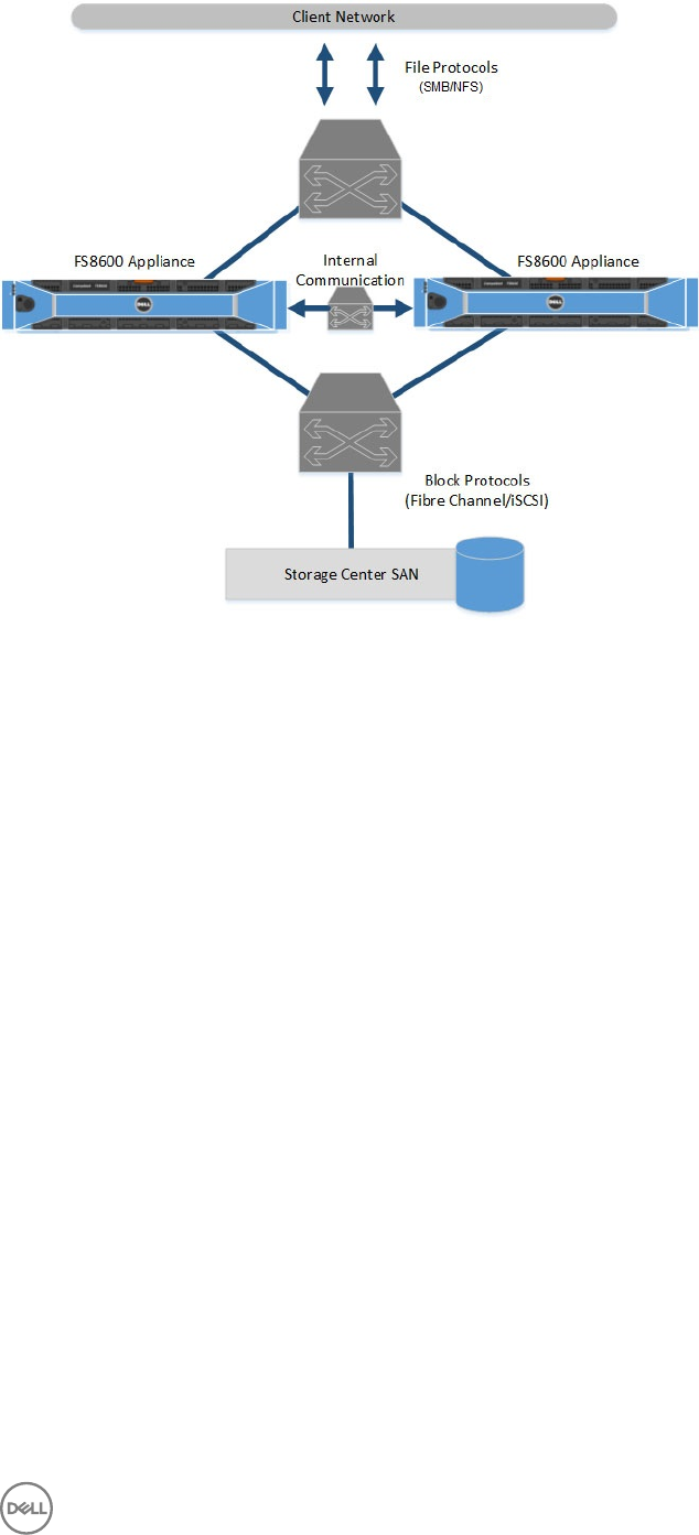
Figure 1. FS8600 Scale-Out NAS Architecture
Storage Center
The Storage Center provides the FS8600 scale-out NAS storage capacity. The FS8600 cannot be used as a standalone NAS
appliance, which eliminates the need to have separate storage capacity for block and le storage. In addition, Storage Center
features, such as Dynamic Capacity and Data Progression, are automatically applied to NAS volumes.
The FS8600 supports the following Storage Center models:
• SC9000
• SC8000
• SC40
• SC4020
• SCv2080
• SC7020
Internal Backup Power Supply
Each NAS controller is equipped with an internal backup power supply (BPS) that protects data during a power failure. The BPS
provides continuous power to the NAS controllers for a minimum of 5 minutes in case of a power failure and has sucient battery
power to allow the NAS controllers to safely shut down. In addition, the BPS provides enough time for the NAS controllers to write
all data from the cache to non-volatile internal storage.
The NAS controllers regularly monitor the BPS battery status, which requires the BPS to maintain a minimum level of power for
normal operation. To ensure the BPS battery status is accurate, the NAS controllers routinely undergo battery calibration cycles.
During a battery calibration cycle, the BPS goes through charge and discharge cycles; therefore, battery error events during this
process are expected. A battery calibration cycle takes up to 7 days to complete. If a NAS controller starts a battery calibration cycle,
and the peer NAS controller BPS has failed, the NAS controllers enter journaling mode, which might impact performance. Therefore,
Dell recommends repairing a failed BPS as soon as possible.
Introduction 7

SAN Network
The FS8600 shares a back-end infrastructure with the Storage Center. The SAN network connects the FS8600 to the Storage
Center and carries the block-level trac. The FS8600 communicates with the Storage Center using either the iSCSI or Fibre
Channel protocol, depending on which NAS appliance conguration you purchased.
LAN/Client Network
The LAN/client network is used for client access to the SMB shares and NFS exports, and it is also used by the storage
administrator to manage the FluidFS cluster. The FluidFS cluster is assigned one or more virtual IP addresses (client VIPs) on the
client network that allow clients to access the FluidFS cluster as a single entity. The client VIP also enables load balancing between
NAS controllers, and ensures failover in the event of a NAS controller failure.
If client access to the FluidFS cluster is not through a router (in other words, a at network), dene one client VIP per cluster. If
clients access the FluidFS cluster through a router, dene a client VIP for each client interface port per NAS controller.
8Introduction

2
Deployment Prerequisites
Verify that the prerequisites are met before proceeding with the deployment process.
Rack and Infrastructure
Make sure the rack space and related infrastructure are available for the FS8600 appliances.
■Prerequisite
□2U rack space for each FS8600 appliance in an industry-standard 48.3 cm (19 inch) rack
• The rack must be four-post, square-hole or round-hole, and tool-less.
• The rack must be rated for 540 kg (1200 pounds) static load or greater.
• The rack depth must be at least 100 cm (40 inches) from the front to the back of the rack.
• The distance between the inside of the front and back rack posts (the mounting surfaces) must be 61 cm (24 inches) to
90 cm (36 inches).
• The rack door and the front of the hardware must have at least 4.1 cm (1.6 inches) between them to accommodate the
front bezel.
• The rack (with installed hardware) must meet the safety requirements of UL 60950-1 and IEC 60950-1.
□Rack has two power sources for each FS8600 appliance, preferably from dierent circuits
• The voltage range must be 90 to 264 VAC.
• Each power source must have sucient electrical overload protection.
– In North America, connect the appliance to a source of power with overcurrent protection provided by a 20 A or less
device (UL 489 circuit breakers).
– In Europe, the overcurrent protection must be provided by a 20 A or less device (IEC circuit breakers).
□Rack has connectivity to the SAN and client networks
Materials
Make sure the following materials are available.
■Prerequisite
□Completed Solution Integration Document (SID)
□VGA monitor and USB keyboard (for initial conguration)
□Cables for SAN
• Fibre Channel with 1GbE appliance or Fibre Channel with 10GbE appliance – Four LC Fibre Channel cables for each
appliance
• 10GbE iSCSI appliance – Four LC optical ber cables or twinax cables for each appliance
□Cables for client network
• Fibre Channel with 1GbE appliance – Eight RJ45/Cat 5e or better cables for each appliance
• Fibre Channel with 10GbE appliance or 10GbE iSCSI appliance – Four LC optical ber cables or Twinax cables for each
appliance
Deployment Prerequisites 9

■Prerequisite
□Cables for internal network
• Fibre Channel with 1GbE appliance:
– Single appliance – Four RJ45/Cat 5e or better cables for each appliance (controllers are directly connected to each
other)
– Multiple appliances – Eight RJ45/Cat 5e or better cables for each appliance
• Fibre Channel with 10GbE appliance:
– Single appliance – Two LC optical ber cables or twinax cables (controllers are directly connected to each other; two
Twinax cables shipped with each appliance)
– Multiple appliances – Four LC optical ber cables or twinax cables for each appliance
• 10GbE iSCSI appliance – None (shared with SAN cables)
□(10GbE optical networks only) Intel SFP+ transceivers purchased from Dell for use in an FS8600 appliance
• Fibre Channel with 10GbE appliance:
– Client network – Four Intel SFP+ transceivers for each appliance
– Internal network – Four Intel SFP+ transceivers for each appliance
• 10GbE iSCSI appliance:
– Client network – Four Intel SFP+ transceivers for each appliance
– SAN/internal network – Four Intel SFP+ transceivers for each appliance
NOTE: The FS8600 appliance is compatible with specic Intel SFP+ transceivers purchased only from Dell. Other
SFP+ transceiver models do not work in the FS8600 appliance.
Network Credentials
Make sure the following network credentials are available to complete the deployment successfully.
■Prerequisite
□(Fibre Channel only) Credentials to update Fibre Channel zoning
□(Active Directory only) Site information and credentials to join the FluidFS cluster to Active Directory
Any of the following domain users can be used to join the cluster to Active Directory:
• Domain administrator account (preferred method)
• Domain account that has been delegated the join a computer to the domain privilege and full control over all
computer objects in the domain
•Domain Organizational Unit (OU) administrator account that has been delegated the join a computer to the
domain privilege and full control over objects within that OU, including computer objects
– Before joining the FluidFS cluster to the domain, a computer object must be created by the OU administrator for the
FluidFS cluster.
– The FluidFS cluster computer object name and NetBIOS name must match.
– The FluidFS cluster computer object permissions must be congured to allow the OU administrator account to join it
to a domain.
□(LDAP/NIS only) Site information and credentials to congure LDAP or NIS directory services for the FluidFS cluster
□(Optional) Credentials to add DNS records for the FluidFS cluster
10 Deployment Prerequisites

SAN and Internal Network for Fibre Channel Appliances
The following prerequisites apply to Fibre Channel with 1GbE appliances and Fibre Channel with 10GbE appliances.
Fibre Channel SAN Fabric
Make sure the Fibre Channel SAN fabric is ready for deployment.
■Prerequisite
□Fibre Channel switches can be reached from the rack.
• At least one switch must be available to connect the FluidFS cluster to the Storage Center. An FS8600 appliance cannot
be connected directly to a Storage Center.
• For high availability, deploy two switches (one for each Storage Center fault domain).
□Fibre Channel switch infrastructure has four ports available for each FS8600 appliance (all four ports must be connected).
Internal Network for Multi-Appliance Clusters
The following prerequisites apply to FluidFS clusters that contain multiple FS8600 appliances. In single-appliance FluidFS clusters,
the internal network ports are connected directly to each other, so no switch prerequisites apply.
■Prerequisite
□1GbE or 10GbE switches can be reached from the rack in a multi-appliance conguration. Although the best practice is to
isolate internal and client trac on separate physical networks, it is possible to use the same switch and use separate logical
networks by conguring VLANs.
□Switch infrastructure has sucient ports available
• Fibre Channel with 1GbE appliance – Eight RJ45 connections for each appliance
• Fibre Channel with 10GbE appliance – Four LC optical ber or SFP+ (twinax) connections for each appliance
□Flow Control is enabled on the switches.
□Unicast storm control is disabled on the switches.
□Jumbo frames are enabled on the switches to support a frame size of 9000 bytes.
• Dell PowerConnect and Force10 switches must be congured to 9216 MTU.
• Switches from vendors other than Dell might require a dierent MTU conguration to accept 9000-byte frames.
□Switches allow multicast between all ports connected to FS8600 appliances.
□IPv6 is enabled on the switch ports connected to FS8600 appliances.
IPv6 link-local addressing is used for internal network communication. Routing of IPv6 trac is not required on the internal
network switches.
□IGMP and/or MLD snooping are disabled on the switch ports connected to FS8600 appliances.
□All switch ports connected to FS8600 appliances are set as edge ports or PortFast to skip Spanning Tree negotiation.
Deployment Prerequisites 11

SAN and Internal Networks for iSCSI Appliances
The following prerequisites apply to 10GbE iSCSI appliances. For these appliances, the iSCSI network and internal network share
10GbE ports and switch infrastructure.
■Prerequisite
□10GbE switches can be reached from the rack.
• At least one switch must be available to connect the FluidFS cluster to the Storage Center. An FS8600 appliance cannot
be connected directly to a Storage Center.
• To connect an FS8600 appliance to an SCv2080 storage system, use a switch that supports both 10GBASE-T and SFP+
connectivity.
• For high availability, deploy two switches (one for each Storage Center fault domain).
□10GbE switch infrastructure has four LC optical or SFP+ (twinax) connections available for each FS8600 appliance
□If you are using VLAN tagging, congure one unique VLAN for each iSCSI subnet (Storage Center fault domain).
□Flow Control is enabled on the switches.
□Unicast storm control is disabled on the switches.
□Jumbo frames are enabled on the switches to support a frame size of 9000 bytes.
• Dell PowerConnect and Force10 switches must be congured to 9216 MTU.
• Switches from vendors other than Dell might require a dierent MTU conguration to accept 9000-byte frames.
□Switches allow multicast between all ports on the iSCSI/internal network.
□IPv6 is enabled on the switch ports connected to FS8600 appliances.
IPv6 link-local addressing is used for internal network communication. Routing of IPv6 trac is not required on the iSCSI/
internal network switches.
□IGMP and/or MLD snooping are disabled on the switch ports connected to FS8600 appliances.
□All switch ports connected to FS8600 appliances are set as edge ports or PortFast to skip Spanning Tree negotiation.
Client Network
Make sure the client network meets the following prerequisites. The client network is used by clients to access SMB shares or NFS
exports. It is also the network used for replication, backup, and administration.
■Prerequisite
□1GbE or 10GbE switches can be reached from the rack.
To ensure high availability to the client network, Dell recommends using a switch stack or Director class switches. Distributing
the client network ports across discrete switches/blades in the stack creates a redundant connection to the core network,
allowing le access to continue after a single switch failure.
□Ethernet switch infrastructure has ports available for each FS8600 appliance.
• Fibre Channel with 1GbE appliance – Eight RJ45 ports for each appliance
• Fibre Channel with 10GbE appliance or 10GbE iSCSI appliance – Four LC optical or SFP+ (twinax) connections for each
appliance
□All client ports are in the same broadcast domain or port-based VLAN.
□Switches are congured to use MTU size equal to or greater than the minimum supported MTU.
• Dell Force10 switches must be congured to use MTU 1554 or greater.
• Dell PowerConnect switches must be congured to use MTU 1518 or greater.
12 Deployment Prerequisites

■Prerequisite
• If jumbo frames are used on the client network, the switches and clients must be congured to use MTU 9000.
□(Recommended but not required) Flow control is enabled on the switches.
IP Addresses and Network Infrastructure
Reserve IP addresses for the FluidFS cluster and record relevant network infrastructure information.
■Prerequisite
□IP addresses reserved for the FluidFS cluster on the client network
• Two controller IP addresses for each appliance (one for each controller)
• Client VIPs (virtual IPs):
– Minimum – One client VIP for each cluster
– Flat network recommendation – One client VIP for each cluster
– Routed network recommendation – One client VIP for each FS8600 client network port
□(iSCSI only) Four IP addresses reserved on the iSCSI SAN network for each appliance (two for each controller)
□Network resource information for FluidFS cluster conguration
• Client network default gateway IP address
• (Optional) DNS server IP addresses
• (Optional) NTP server host name or IP addresses
• (Optional) Active Directory FQDN and administrator credentials to join domain or OU in a domain.
• (Optional) LDAP server host name or IP addresses
• (Optional) NIS server host name or IP addresses
• (Optional) NDMP DMA server IP addresses
• (Optional) Antivirus server host names or IP addresses
Network Ports
Make sure the required and feature-specic ports are allowed on the network.
For a list of ports used by the FluidFS cluster, see the Dell Fluid File System Version 6 Support Matrix. This matrix is available from
dell.com/support.
■Prerequisite
□Required ports are allowed
□Feature-specic ports are allowed as needed
SAN Conguration
Make sure that Storage Center software and Dell Storage Manager software are installed and satisfy the deployment prerequisites.
■Prerequisite
□The Storage Center systems are running the required version of Storage Center software:
• An SC9000 storage system requires Storage Center 6.7.3 or later.
• An SC8000 storage system requires Storage Center 6.5.10 or later.
• An SC7020 storage system requires Storage Center 7.1.4 or later.
• An SC40 storage system requires Storage Center 6.5.10 or later.
Deployment Prerequisites 13

■Prerequisite
• An SC4020 storage system requires Storage Center 6.5.10 or later.
• An SCv2080 storage system requires Storage Center 6.6.4 or later.
NOTE: A single FluidFS cluster supports up to eight Storage Centers.
• For deployment instructions, see the Dell Storage Center Deployment Guide.
• For upgrade instructions, see the Dell Storage Center Software Update Guide.
□Each Storage Center certicate contains the host name or management IP address used to add the Storage Center to Dell
Storage Manager. For instructions on regenerating an SSL certicate, see the Storage Center Administrator's Guide.
□(Optional) Storage Centers can be reached by Copilot through Secure Console to assist with troubleshooting.
□Dell Storage Manager 2016 R3 or later software is installed and congured.
NOTE: Dell recommends using the latest version of Dell Storage Manager software.
See the Dell Storage Manager Installation Guide for detailed instructions.
□The Storage Center systems are added to Dell Storage Manager.
□Dell Storage Manager can successfully send data to Dell Technical Support using SupportAssist.
14 Deployment Prerequisites

3
Install and Connect the FS8600 Hardware
Install the FS8600 appliances in a rack and connect the SAN, internal, and client networks.
Install the FS8600 Hardware
Unpack the hardware and mount it in a rack.
Prerequisites
The rack must meet the prerequisites listed in Rack and Infrastructure.
Steps
1. Unpack the hardware.
2. Locate the following components for each appliance:
• FS8600 appliance
• Bezel
• Two power cables
• Rail kit
• SFP+ transceivers (if ordered for optical networks)
• (Fibre Channel with 10GbE appliances only) Two 1-meter twinax cables (for single-appliance internal network connectivity
between controllers)
• Two port label tags (one attached to each controller)
• Cable labels
3. Mount each FS8600 appliance in the rack. See the document included with the rail kit for instructions.
4. Connect both controllers in each FS8600 appliance to a power source.
Congure Network Connections for FC Appliances (1GbE)
Connect Fibre Channel 1GbE appliances to the client network, internal network, and Fibre Channel SAN.
Connect FC Appliances (1GbE)
Connect the FS8600 appliances to the Fibre Channel SAN fabric, internal network, and client network.
Prerequisites
• LC optical ber and Ethernet cables must be available. See Materials.
• The SAN network must meet conguration requirements. See SAN and Internal Network for Fibre Channel Appliances.
• The client network must meet conguration requirements. See Client Network.
Steps
1. Identify the ports on an FC FS8600 appliance (1GbE).
Install and Connect the FS8600 Hardware 15
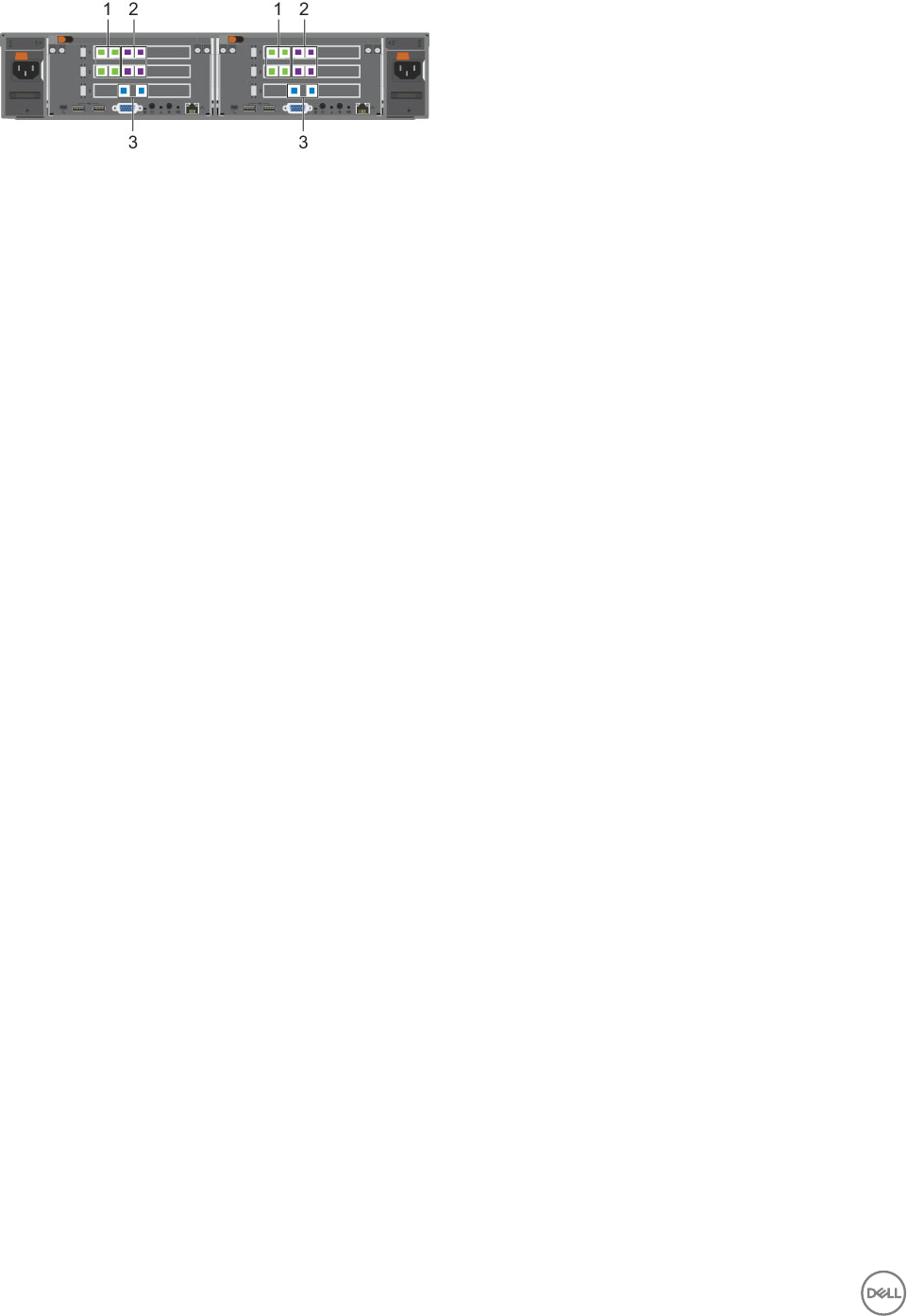
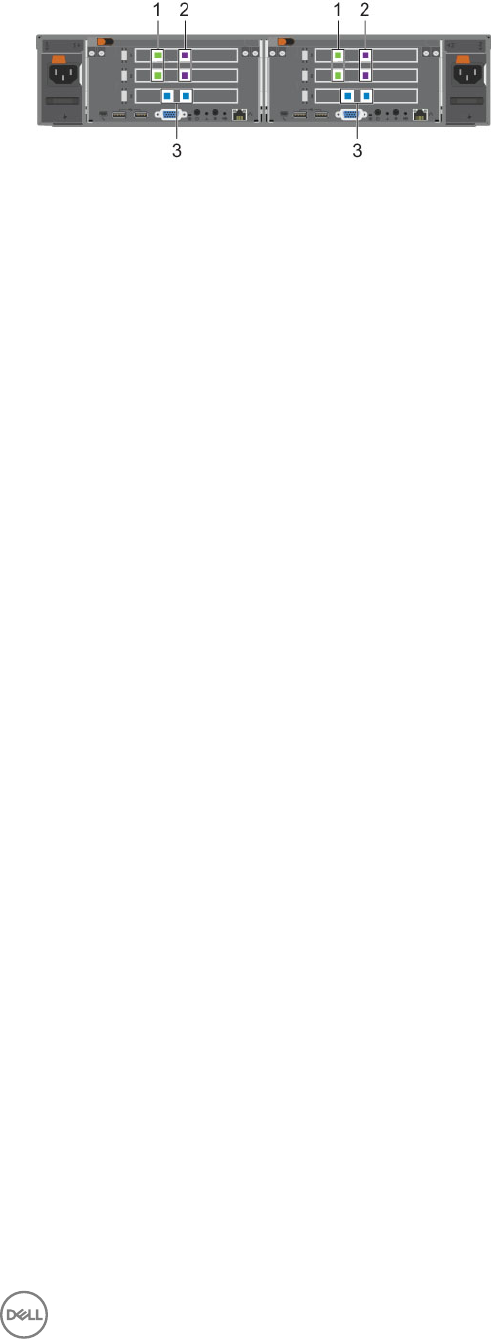
Figure 2. FC FS8600 Appliance Ports (1GbE)
1. Client network ports 2. Internal network ports
3. Fibre Channel ports
2. Connect each appliance to the Fibre Channel SAN fabric.
• For each controller, use LC optical ber cables to connect both Fibre Channel ports to the fabric.
• If the cluster has two Fibre Channel fabrics (Storage Center fault domains), make sure each controller is connected to both
fabrics.
3. Connect each appliance to the internal network.
• Single-appliance cluster:
– Use Category 5e or better Ethernet cables to directly connect each controller 0 internal port to the corresponding
controller 1 internal port.
– Make sure all four internal ports are connected for each controller.
• Multi-appliance cluster:
– Use Category 5e or better Ethernet cables to connect all controller internal ports to the internal network Ethernet
switches.
– Make sure all four internal ports are connected for each controller.
4. Connect each appliance to the client network.
• For each controller, use Category 5e or better Ethernet cables to connect all four client ports to client network Ethernet
switches.
• If the cluster has multiple switches, make sure each controller is connected to each switch.
5. Use the cable labels shipped with the appliance to label each cable.
Example of Single-Appliance FC 1GbE Cluster Conguration
The following example shows the best-practices conguration for single-appliance Fibre Channel 1GbE clusters.
• Client network – Each FS8600 controller has multiple connections to each stacked Ethernet switch.
• Internal network – The FS8600 controllers are directly connected to each other with four Ethernet cables.
• Fibre Channel SAN – Each FS8600 controller has a connection to each FC fabric (Storage Center fault domain).
16 Install and Connect the FS8600 Hardware
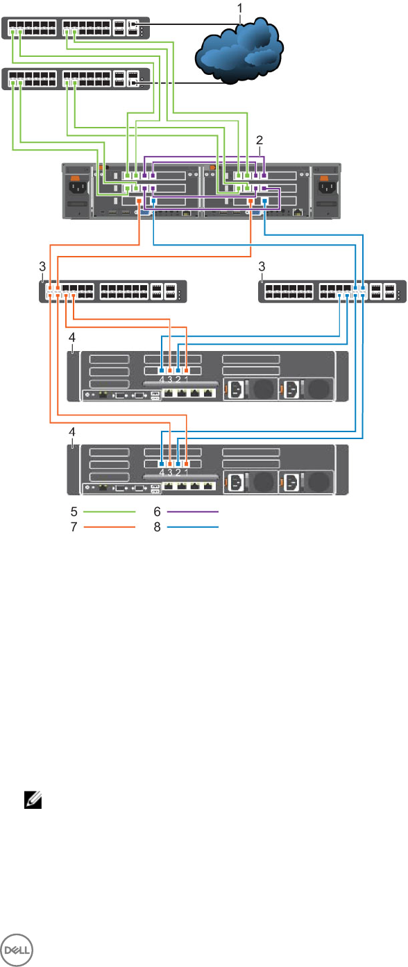
Figure 3. Single-Appliance Fibre Channel 1GbE Cluster Conguration With an SC9000 Storage System
1. Client network 2. Internal network
3. Fibre Channel SAN switch 4. SC9000 with 1Gb FC ports
5. Client network connections 6. FS8600 internal network connections
7. Storage Center fault domain 1 connections 8. Storage Center fault domain 2 connections
Example of Multi-Appliance FC 1GbE Cluster Conguration
The following example shows the best-practices conguration for multi-appliance Fibre Channel 1GbE clusters.
• Client network – Each FS8600 controller has multiple connections to each stacked Ethernet switch.
• Internal network – Each FS8600 controller has multiple connections to the stacked internal network Ethernet switches.
• Fibre Channel SAN – Each FS8600 controller has a connection to each FC fabric (Storage Center fault domain).
NOTE: To simplify the diagram, only one FS8600 appliance is shown. Additional appliances in the cluster must be
connected to the same client network, internal network, and FC SAN fabric.
Install and Connect the FS8600 Hardware 17
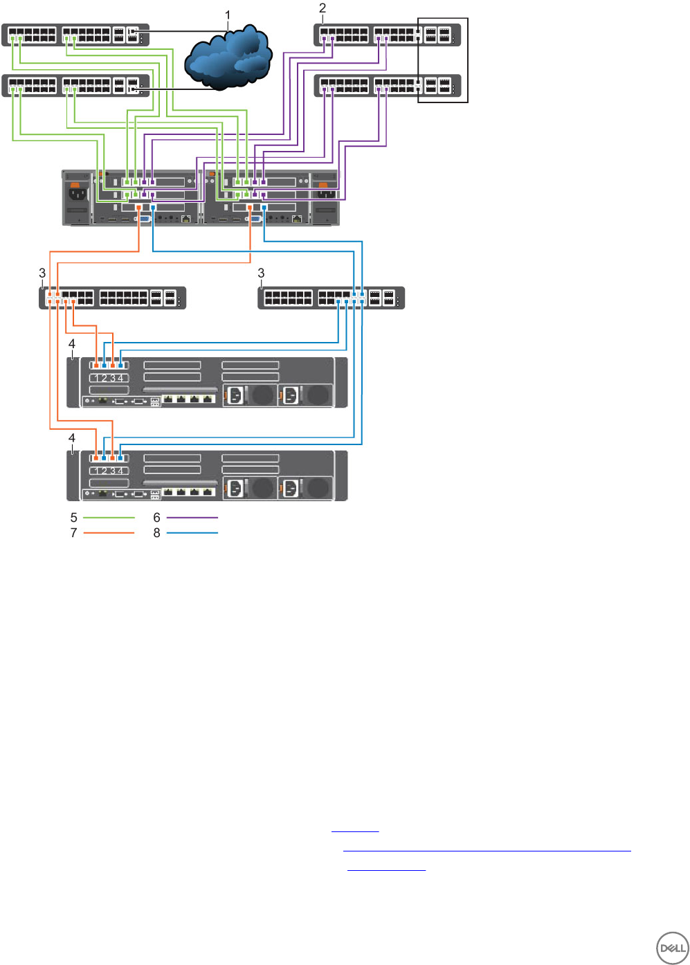
Figure 4. Multi-Appliance Fibre Channel 1GbE Cluster Conguration With an SC8000 Storage System
1. Client network 2. Internal network
3. Fibre Channel SAN switch 4. SC8000 with 1Gb FC ports
5. Client network connections 6. Internal network connections
7. Storage Center fault domain 1 connections 8. Storage Center fault domain 2 connections
Congure Network Connections for FC Appliances (10GbE)
Connect Fibre Channel 10GbE appliances to the client network, internal network, and Fibre Channel SAN.
Connect FC FS8600 Appliances (10GbE)
Connect the FS8600 appliances to the Fibre Channel SAN fabric, internal network, and client network.
Prerequisites
• LC optical ber and/or twinax cables must be available. See Materials.
• The SAN network must meet conguration requirements. See SAN and Internal Network for Fibre Channel Appliances.
• The client network must meet conguration requirements. See Client Network.
18 Install and Connect the FS8600 Hardware
Steps
1. Identify the ports on an FC FS8600 appliance (10GbE).
Figure 5. FC FS8600 Appliance Ports (10GbE)
1. Client network ports 2. Internal network ports
3. Fibre Channel ports
2. Connect each appliance to the Fibre Channel SAN fabric.
• For each controller, use LC optical ber cables to connect both Fibre Channel ports to the fabric.
• If the cluster has two Fibre Channel fabrics (Storage Center fault domains), make sure each controller is connected to both
fabrics.
3. Connect each appliance to the internal network.
• Single-appliance cluster:
– Use twinax cables to directly connect each controller 0 internal port to the corresponding controller 1 internal port.
– Make sure both internal ports are connected for each controller.
• Multi-appliance cluster:
– Use LC optical ber or twinax cables to connect all controller internal ports to the internal network Ethernet switches.
– Make sure both internal ports are connected for each controller.
4. Connect each appliance to the client network.
• For each controller, use LC optical ber or twinax cables to connect both client ports to client network Ethernet switches.
• If the cluster has multiple switches, make sure each controller is connected to each switch.
5. Use the cable labels shipped with the appliance to label each cable.
Example of Single-Appliance FC 10GbE Cluster Conguration
The following example shows the best-practices conguration for single-appliance Fibre Channel 10GbE clusters.
• Client network – Each FS8600 controller has a connection to each stacked Ethernet switch.
• Internal network – The FS8600 controllers are directly connected to each other with two twinax cables.
• Fibre Channel SAN – Each FS8600 controller has a connection to each FC fabric (Storage Center fault domain).
Install and Connect the FS8600 Hardware 19
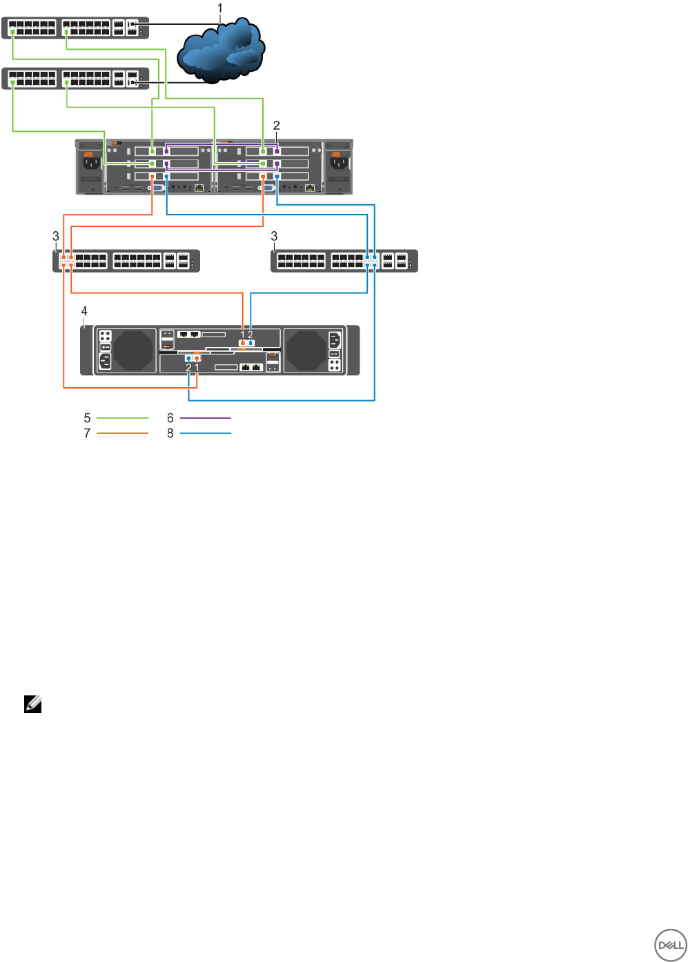
Figure 6. Single-Appliance Fibre Channel 10GbE Cluster Conguration With an SC4020 Storage System
1. Client network 2. Internal network
3. Fibre Channel SAN switch 4. SC4020 with 10Gb FC ports
5. Client network connections 6. FS8600 internal network connections
7. Storage Center fault domain 1 connections 8. Storage Center fault domain 2 connections
Example of Multi-Appliance FC 10GbE Cluster Conguration
The following example shows the best-practices conguration for multi-appliance Fibre Channel 10GbE clusters.
• Client network – Each FS8600 controller has multiple connections to each stacked Ethernet switch.
• Internal network – Each FS8600 controller has multiple connections to the stacked internal network Ethernet switches.
• Fibre Channel SAN – Each FS8600 controller has a connection to each FC fabric (Storage Center fault domain).
NOTE: To simplify the diagram, only one FS8600 appliance is shown. Additional appliances in the cluster must be
connected to the same client network, internal network, and FC SAN fabric.
20 Install and Connect the FS8600 Hardware
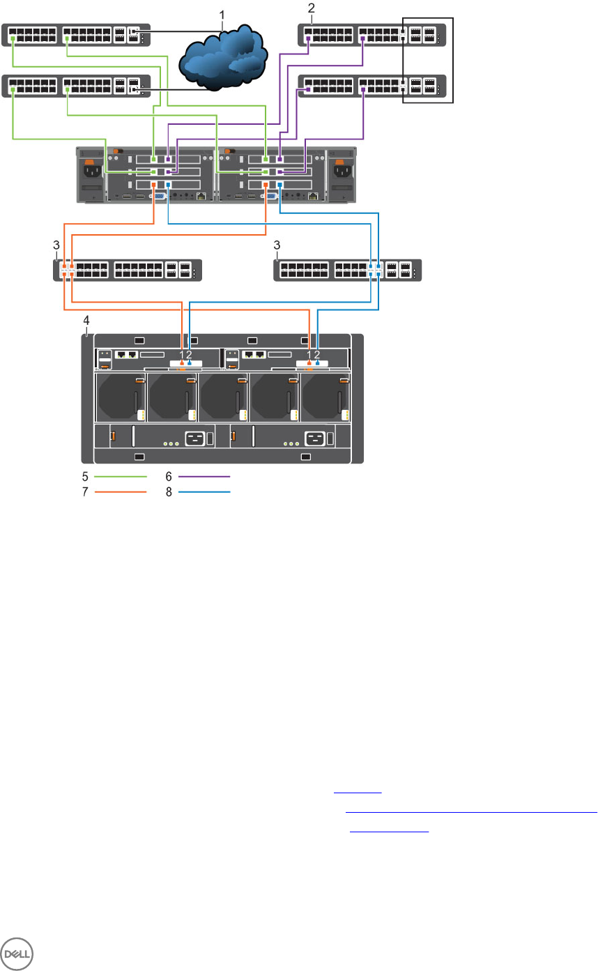
Figure 7. Multi-Appliance Fibre Channel 10GbE Cluster Conguration With an SCv2080 Storage System
1. Client network 2. Internal network
3. Fibre Channel SAN switch 4. SCv2080 with 10Gb FC ports
5. Client network connections 6. Internal network connections
7. Storage Center fault domain 1 connections 8. Storage Center fault domain 2 connections
Congure Network Connections for 10GbE iSCSI Appliances
Connect 10GbE iSCSI appliances to the SAN/internal network and client network.
Connect 10GbE FS8600 iSCSI Appliances
Connect the FS8600 appliances to the SAN/internal network and client network.
Prerequisites
• LC optical ber and/or twinax cables must be available. See Materials.
• The SAN network must meet conguration requirements. See SAN and Internal Networks for iSCSI Appliances.
• The client network must meet conguration requirements. See Client Network.
Steps
1. Identify the ports on a 10GbE iSCSI FS8600 appliance.
Install and Connect the FS8600 Hardware 21
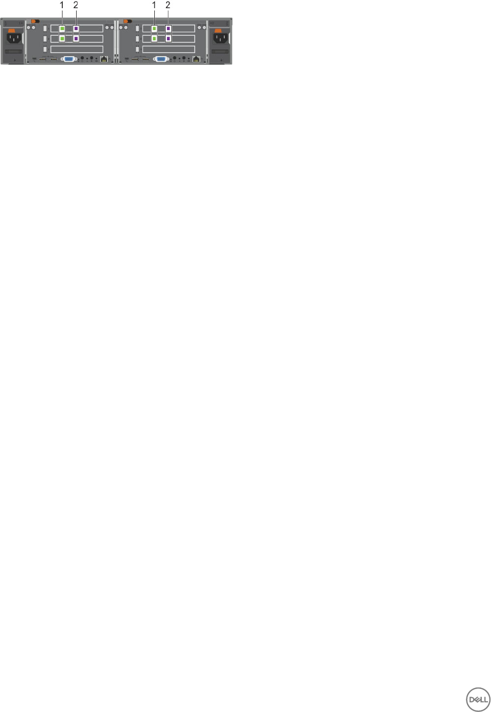
Figure 8. 10GbE iSCSI FS8600 Appliance Ports
1. Client network ports 2. Internal/iSCSI ports
2. Connect each appliance to the SAN/internal network.
• Use LC optical ber or twinax cables to connect all controller internal/iSCSI ports to the SAN/internal network Ethernet
switches.
– For all controllers, eth30 (upper right port), must be connected to the same subnet.
– For all controllers, eth31 (lower right port), must be connected to the same subnet.
• Make sure each controller is connected to each switch.
3. Connect each appliance to the client network.
• For each controller, use LC optical ber or twinax cables to connect both client ports to client network Ethernet switches.
• Make sure each controller is connected to each switch.
4. Use the cable labels shipped with the appliance to label each cable.
Example of 10GbE iSCSI Cluster Conguration
The following examples show the best-practices conguration for 10GbE iSCSI clusters.
• Client network – Each FS8600 controller has multiple connections to each stacked Ethernet switch.
• SAN/Internal network – Each FS8600 controller has multiple connections to the stacked internal/SAN network Ethernet
switches.
– Internal trac between the FS8600 controllers is untagged.
22 Install and Connect the FS8600 Hardware
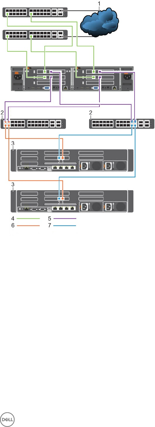
Figure 9. 10GbE iSCSI Cluster Conguration With an SC9000 Storage System
1. Client network 2. Internal/iSCSI SAN switch
3. SC9000 with 10GbE iSCSI ports 4. Client network connections
5. Untagged VLAN – FS8600 internal network connections 6. VLAN Storage Center SAN A connections
7. VLAN Storage Center SAN B connections
Install and Connect the FS8600 Hardware 23
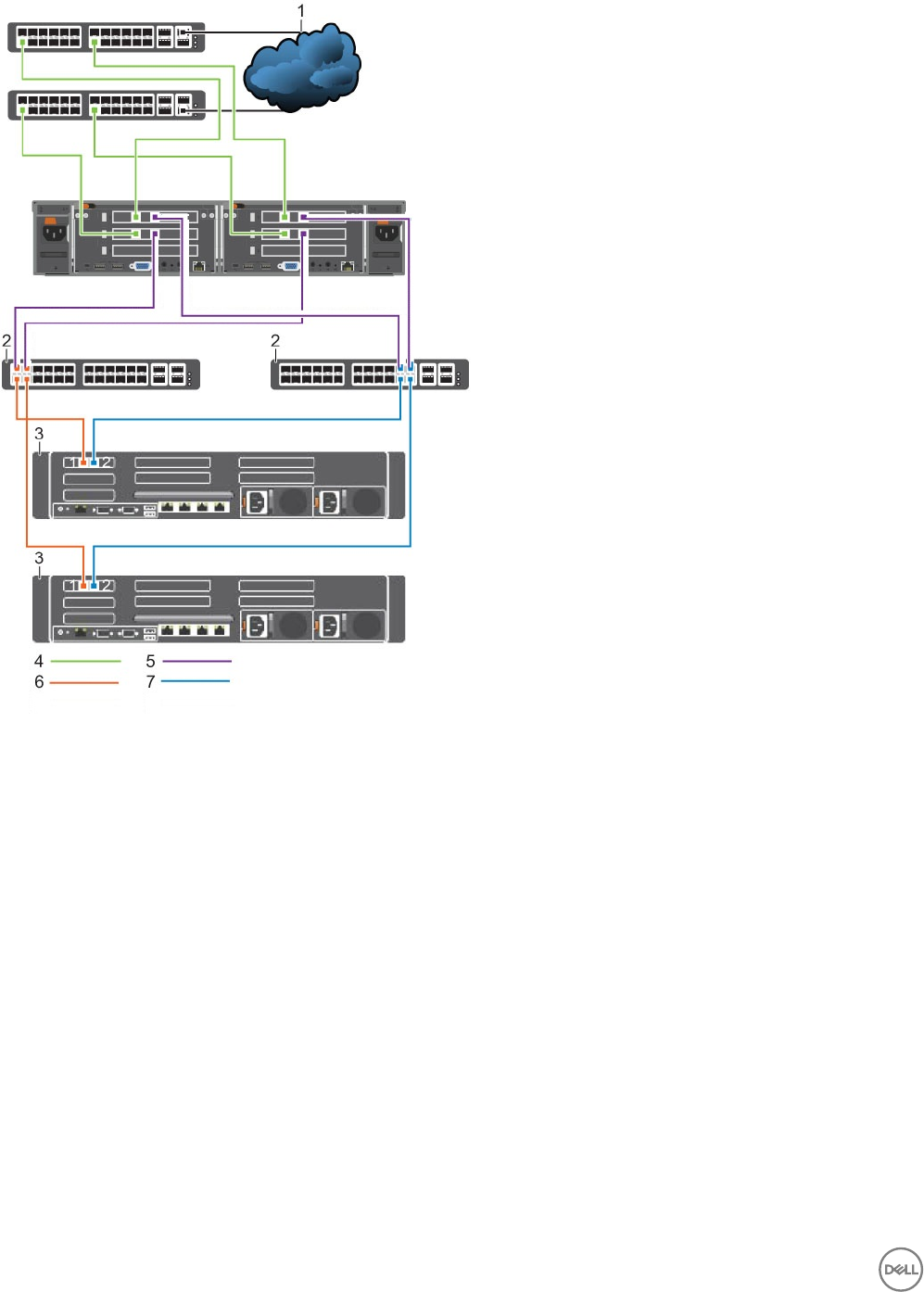
Figure 10. 10GbE iSCSI Cluster Conguration With an SC8000 Storage System
1. Client network 2. Internal/iSCSI SAN switch
3. SC8000 with 10GbE iSCSI ports 4. Client network connections
5. Untagged VLAN – FS8600 internal network connections 6. VLAN Storage Center SAN A connections
7. VLAN Storage Center SAN B connections
24 Install and Connect the FS8600 Hardware
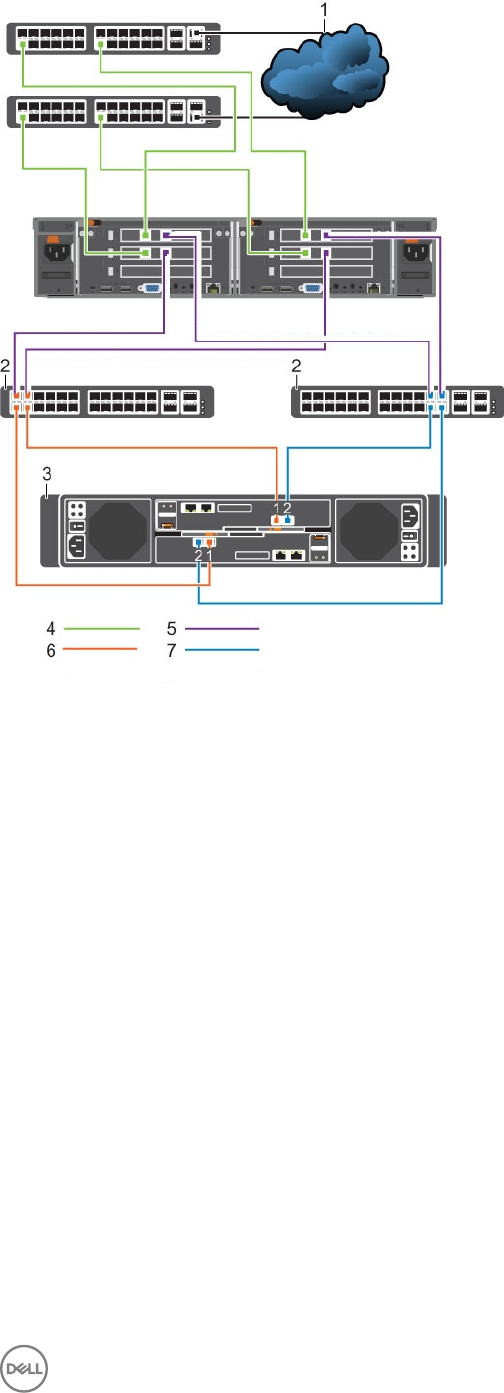
Figure 11. 10GbE iSCSI Cluster Conguration With an SC4020 Storage System
1. Client network 2. Internal/iSCSI SAN switch
3. SC4020 with 10GbE iSCSI ports 4. Client network connections
5. Untagged VLAN – FS8600 internal network connections 6. VLAN Storage Center SAN A connections
7. VLAN Storage Center SAN B connections
Install and Connect the FS8600 Hardware 25
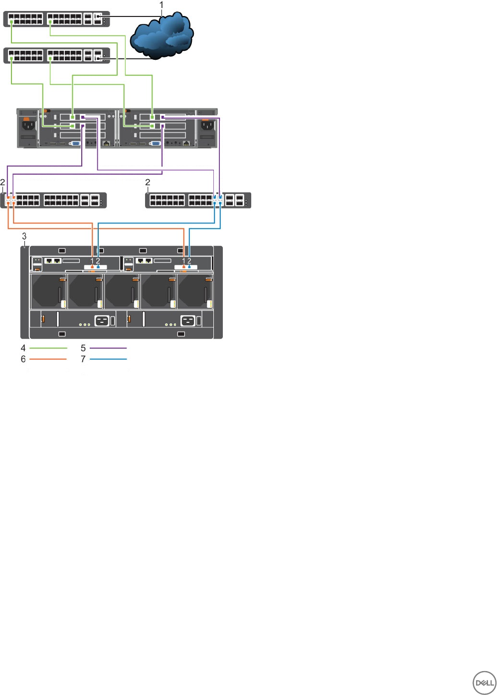
Figure 12. 10GbE iSCSI Cluster Conguration With an SCv2080 Storage System
1. Client network 2. Internal/iSCSI SAN switch
3. SCv2080 with 10GbE iSCSI ports 4. Client network connections
5. Untagged VLAN – FS8600 internal network connections 6. VLAN Storage Center SAN A connections
7. VLAN Storage Center SAN B connections
26 Install and Connect the FS8600 Hardware

4
Congure the FluidFS Cluster
Set the initial IP address for the rst FS8600 appliance, then use Dell Storage Manager to congure the FluidFS cluster.
Congure FluidFS Cluster Network Settings
Use the CLI to congure initial IP addresses for the rst appliance.
Connect to the FluidFS Cluster CLI
Connect to the FluidFS cluster CLI using either a VGA console or the iBMC virtual KVM.
Connect to the FluidFS Cluster CLI Using a VGA Console
Log in to the CLI using a VGA console. If you chose this method, you can skip the Connect to the CLI using iBMC Virtual KVM steps.
Prerequisites
• You must have a USB keyboard and VGA monitor.
• All controllers in the cluster must be running the same FluidFS version. If the controllers shipped from the factory with FluidFS
5.0, update to the latest 6.0 version before continuing with deployment. Alternatively, you can deploy with FluidFS v5 and update
to FluidFS v6.
• All controllers in the cluster must be powered on in standby mode.
Steps
1. Connect a VGA monitor and USB keyboard to controller 0.
• Controller 0 is located on the left when viewed from the rear in the rst appliance.
• If you are conguring a multi-appliance cluster, connect to controller 0 in the rst appliance.
2. From the command line, type the following command at the next login as prompt: cli
3. Type the FluidFS cluster administrator user name at the login as prompt. The default user name is Administrator.
4. Type the FluidFS cluster administrator password at the
<user_name>
’s password prompt. The default password is Stor@ge!.
You are logged in to the CLI and a Welcome window opens. The window lists the available menus.
Connect to the FluidFS Cluster CLI Using the iBMC Virtual KVM
Log in to the CLI using the iBMC (Integrated Baseboard Management Controller) virtual KVM. If you choose this method, you can
skip the Connect to the CLI Using a VGA Console steps.
Prerequisites
• You must have a laptop with Java installed.
• All controllers in the cluster must be running the same FluidFS version. If the controllers shipped from the factory with FluidFS
5.0, update to the latest FluidFS 6.0 version before continuing with deployment. Alternatively, you can deploy with FluidFS v5 and
update to FluidFS v6.
• All controllers in the cluster must be powered on in standby mode.
Steps
1. Connect a laptop to the LOM (Lights Out Management) port on controller 0 using a Cat 5/6 cable.
• Controller 0 is located on the left when viewed from the rear in the rst appliance.
• The LOM port is located on the lower right when viewed from the rear of a controller.
• If you are conguring a multi-appliance cluster, connect to controller 0 in the rst appliance.
2. Set the LAN port IP address of the laptop to 192.168.254.200/255.255.255.0.
Congure the FluidFS Cluster 27

3. Open a web browser on the laptop. In the address bar of the web browser, type http://192.168.254.253. The iBMC
login page opens.
4. Log in to the iBMC. The user name is ADMIN and the password is N@sst0r3.
5. Click Launch Java KVM Client. The FluidFS cluster CLI opens.
6. From the command line, type the following command at the next login as prompt: cli
7. Type the FluidFS cluster administrator user name at the login as prompt. The default user name is Administrator.
8. Type the FluidFS cluster administrator password at the
<user_name>
’s password prompt. The default password is Stor@ge!.
You are logged in to the CLI and a Welcome window opens. The window lists the available commands in the main menu.
Congure Cluster IP Addresses and the Default Gateway
Congure the client subnet mask, optional VLAN ID, controller IP addresses, a client VIP, and default route for the rst appliance. IP
addresses and VIPs for additional appliances can be congured at this time or congured later by Dell Storage Manager.
Prerequisites
IP addresses must be reserved for the FluidFS cluster on the client network. See IP Addresses and Network Infrastructure.
Steps
1. Use the following command to add a client subnet. Specify the client subnet mask, optional VLAN ID, and an IP address for
each controller on this subnet.
CLI> environment network subnets add <Prefix_Length> [-VLANTag <VLAN ID>] ‑PrivateIPs
<IP1, IP2>
Example:
environment network subnets add 16 -VLANTag 0 -PrivateIPs 198.51.100.16,198.51.100.1
2. For IPv4, use the following command to congure the default gateway:
CLI> environment network default-gateway add-IPv4 [gateway_IP_address]
For IPv6, use the following command to congure the default gateway:
CLI> environment network default-gateway add-IPv6 [gateway_IP_address]
3. Add at least one client VIP in the same subnet as dened in Step 1 : CLI> client-access DNS-and-VIPs public-
ips add <IP>
Use Dell Storage Manager to Congure the FluidFS Cluster
Make sure that you have the IP addresses, netmask numbers, and NAS environment items that were discovered when the FS8600
Pre-Deployment Requirements process was completed.
Prerequisites
Before conguring the FluidFS cluster with Dell Storage Manager, ensure that you have met the following requirements.
■Prerequisite
□Dell Storage Manager and Storage Center are deployed and congured. See SAN Conguration.
□You have the required network credentials. See Network Credentials.
□LAN/client network IP addresses (and, optionally, the default gateway) have been congured on the FS8600 using the
command-line interface.
□Required ports are allowed on the network. See the FluidFS v6 Support Matrix for specic port information.
□The FluidFS cluster is connected to the SAN, client network, and internal network. See Install and Connect the FS8600
Hardware.
NOTE: To congure a FluidFS cluster with an SCv2080 storage system, a volume must exist on the storage system.
□Verify that the iSCSI MTU is set to 9000.
28 Congure the FluidFS Cluster
Log In to Dell Storage Manager
Use the Dell Storage Manager Client to log in to the Dell Storage Manager Data Collector.
Prerequisites
The Dell Storage Manager user account must have the Administrator privilege to view, manage, or add FluidFS clusters in the Dell
Storage Manager Client.
Steps
1. Start the Dell Storage Manager Client application.
2. In the User Name eld, type the Dell Storage Manager Data Collector user name.
3. In the Password eld, type the Dell Storage Manager Data Collector password.
4. In the Host/IP eld, type the host name or IP address of the server that hosts the Data Collector. If the Data Collector and Dell
Storage Manager Client are installed on the same system, you can type localhost instead.
5. If you changed the Web Server Port during installation, type the updated port in the Web Server Port eld.
6. Click Log In. The Dell Storage Manager Client connects to the Data Collector and displays the Storage view, including FluidFS
clusters.
Figure 13. Dell Storage Manager — Storage View
Add the FluidFS Cluster to Dell Storage Manager
Add the FluidFS cluster to Dell Storage Manager to complete initial conguration.
1. In the Dell Storage Manager Client, click the Storage view.
2. In the left pane, select FluidFS Clusters.
3. In the right pane, click Add FluidFS Cluster.
The Add FluidFS Cluster wizard starts and opens the Register FluidFS Cluster w/ Dell Storage Manager page.
Select Appliances
Use the Add Appliance button to include additional appliances in the cluster and the Remove Appliance button to exclude additional
appliances from the cluster.
About this task
Use this page of the Add FluidFS Cluster wizard to add appliances to or remove appliances from the FluidFS cluster.
Congure the FluidFS Cluster 29
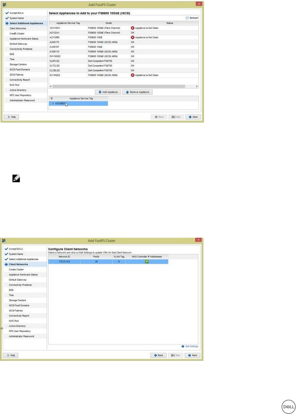
Figure 14. Add FluidFS Cluster Wizard — Select Appliances Page
Steps
1. Add or remove appliances from the cluster.
• To add an appliance, select an appliance in the upper pane, then click Add Appliance.
• To remove an appliance, select an appliance in the lower pane, then click Remove Appliance.
NOTE: All appliances in a single cluster must be the same model.
2. Click Next.
The Congure Client Network page opens.
Congure the Client Network
Add the remaining client VIPs and controller IP addresses.
About this task
Use this page of the Add FluidFS Cluster wizard to congure additional client VIPs and congure the controller IP addresses.
Figure 15. Add FluidFS Cluster Wizard — Congure Client Network Page
30 Congure the FluidFS Cluster
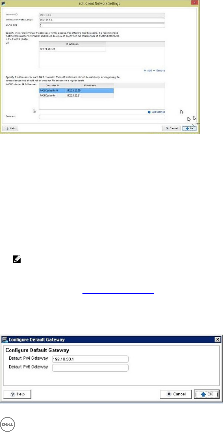
Figure 16. Edit Client Network Settings
Steps
1. Conrm that the Netmask or Prex Length and VLAN Tag elds display the correct netmask or prex length and VLAN ID for
the client network. Modify these elds if necessary.
2. In the Virtual IP Addresses table, dene additional client VIPs for the cluster. To add a VIP, click Add, type the IP address in the
dialog box, and then click OK.
• Minimum requirement – One client VIP for each cluster
• Flat network recommendation – One client VIP for each cluster
• Routed network recommendation – One client VIP for each FS8600 client network port
3. In the Controller IP Addresses table, dene an IP address for each controller in the cluster.
a. Select the controller in the table, then click Edit Settings.
b. In the IP Address eld, type an IP address for the controller.
c. Click OK.
4. Click Next. An Add FluidFS Cluster progress page opens while the cluster is being created.
NOTE: The cluster creation process takes about 10 minutes.
• When the process is complete, if you congured a default gateway for the FluidFS cluster using the CLI before running the
Add FluidFS Cluster wizard, the Set Support User Password page opens.
• When the process is complete, if you have not congured a default gateway for the FluidFS cluster, the Congure Default
Gateway page opens. See Congure the Default Gateway.
Congure the Default Gateway
Specify an IP address for the default route for the cluster.
About this task
Use this page of the File System tab to congure the default gateway address of the FluidFS cluster.
Figure 17. Congure Default Gateway Page
Congure the FluidFS Cluster 31
Steps
1. Click the Storage view and select a FluidFS cluster.
2. In the File System view, select Cluster Connectivity, and click the Client Network tab.
3. In the Static Route panel, click Congure Default Gateway.
The Congure Default Gateway dialog box opens.
4. In the Default IPvn Gateway eld, type a new default gateway IP address.
To provide a default gateway for IPv4 and IPv6 addresses, you need a client subnet of the appropriate type that contains the
default gateway.
5. Click OK.
Congure DNS Settings
Specify IP addresses for DNS servers and DNS suxes for the network.
About this task
Use this page of the Add FluidFS Cluster wizard to congure the DNS settings of the FluidFS cluster.
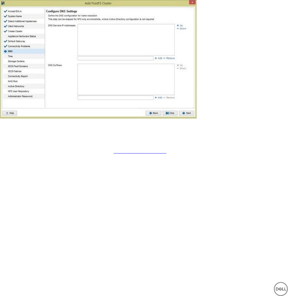
Figure 18. Add FluidFS Cluster Wizard — Congure DNS Settings Page
Steps
1. (Optional) To skip DNS conguration, select the Skip DNS Conguration checkbox and click Next.
The Congure Time Settings page opens. See Congure Time Settings.
2. In the DNS Servers IP Addresses area, specify DNS servers that the FluidFS cluster should use for name resolution.
• To dene a DNS server, type the server IP address in the eld, then click Add.
• To remove a DNS server, select the server IP address, then click Remove.
• To increase or decrease the order of preference for a DNS server, select the server IP address, then click Up or Down.
3. In the DNS Suxes area, specify DNS suxes that the FluidFS cluster should use for name resolution.
• To dene a DNS sux, type the sux in the eld, then click Add.
• To remove a DNS sux, select the sux, then click Remove.
• To increase or decrease the order of preference for a DNS sux, select the sux, then click Up or Down.
4. Click Next.
The Congure Time Settings page opens.
Congure Time Settings
Congure the time zone for the FluidFS cluster. The cluster can also be congured to synchronize time settings with NTP (Network
Time Protocol) servers.
About this task
Use this page of the Add FluidFS Cluster wizard to congure the time settings of the FluidFS cluster.
32 Congure the FluidFS Cluster
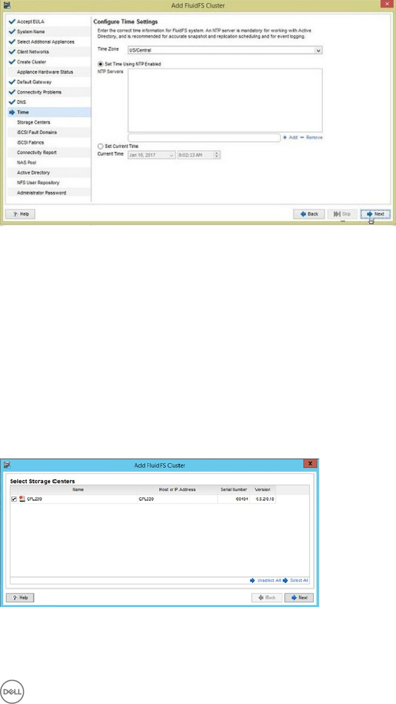
Figure 19. Add FluidFS Cluster Wizard — Congure Time Settings Page
Steps
1. From the Time Zone drop-down menu, select the time zone where the FluidFS cluster is located.
2. (Optional) Congure the cluster to synchronize time with one or more NTP servers.
a. Add an NTP server by typing a host name or IP address in the eld and clicking Add.
b. Select the Set Time Using NTP Enabled checkbox.
c. If the time displayed in the Current Time eld is correct, click OK.
d. To change the current time, clear the Set Time Using NTP Enabled checkbox.
e. From the Current Time drop-down list, select the date and time.
3. Click Next.
The Select Storage Centers page opens.
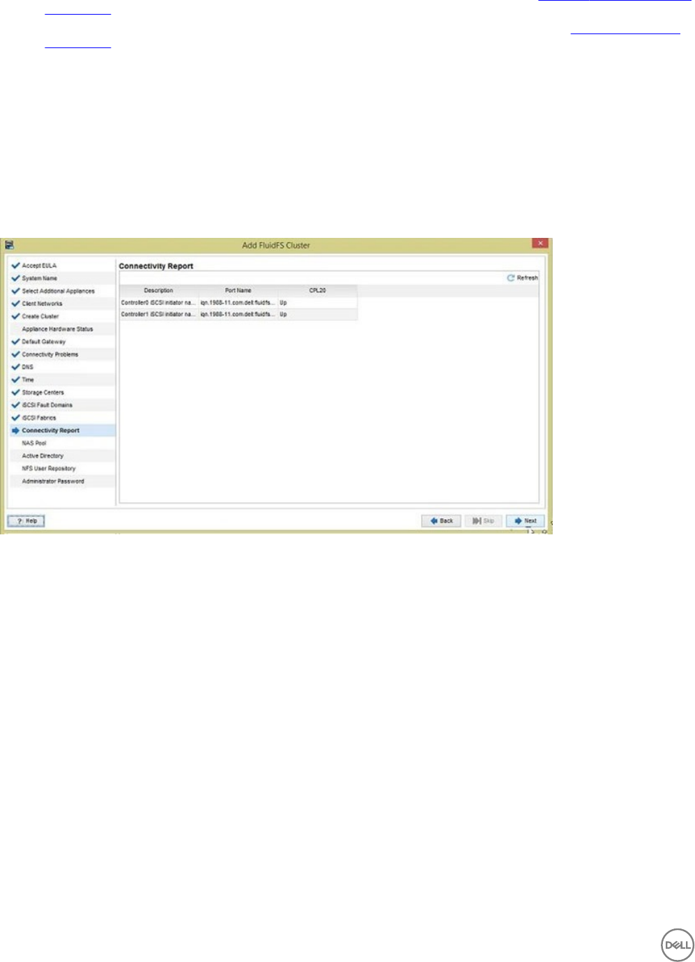
Select Storage Centers
Select Storage Centers to provide storage for the FluidFS cluster NAS pool. Starting with FluidFS v5, you can select an unlimited
number of Storage Centers.
About this task
Use this page of the Add FluidFS Cluster wizard to select the Storage Centers to use for storage in the FluidFS cluster.
Figure 20. Add FluidFS Cluster Wizard — Select Storage Centers Page
Steps
1. Select the Storage Centers.
2. Click Next.
Congure the FluidFS Cluster 33
• If the FluidFS cluster has Fibre Channel appliances, the Connectivity Report page opens. See Congure Fibre Channel SAN
Connectivity.
• If the FluidFS cluster has 10GbE iSCSI appliances, the Select iSCSI Fault Domains page opens. See Congure iSCSI SAN
Connectivity.
Congure Fibre Channel SAN Connectivity
Record the FluidFS World Wide Names and congure Fibre Channel zoning to allow the FluidFS cluster FC ports to communicate
with the Storage Center front-end FC ports.
Record FluidFS World Wide Names
Use the Connectivity Report page to record the World Wide Name (WWN) for each FluidFS Fibre Channel port.
To verify connectivity between the FluidFS cluster and the Storage Center, use the Connectivity Report page. The NAS controller
ports must show the status as Up before you can complete the wizard. if you click Finish and the NAS controller ports do not have
the Up status, an error is displayed.
Figure 21. Add FluidFS Cluster Wizard — Connectivity Report Page
Congure Fibre Channel Zoning
Congure Fibre Channel zoning to allow the FluidFS cluster FC ports to communicate with the Storage Center front-end FC ports.
Fibre Channel Zoning Minimum Requirements
• All ports on the FS8600 appliances must be visible to all Storage Center controllers providing storage.
– Storage Center in legacy mode – Zones must include the WWN of the primary port for each fault domain (WWN zoning) or
the physical switch port of both the primary and reserve ports (port zoning).
– Storage Center in virtual port mode – Zones must include the WWN of the virtual port (WWN zoning) or the physical switch
ports for all ports in the fault domain (port zoning).
• For dual-controller Storage Centers, each FS8600 appliance controller must be in the same FC zones with both Storage Center
controllers.
Fibre Channel Zoning Recommendations
• Each FS8600 appliance controller port should have a unique zone. Multiple FS8600 appliance controller ports should not be
included in one large zone.
• Do not include multiple Storage Centers in a single FS8600 appliance controller zone. If the FluidFS cluster uses two Storage
Centers, each Storage Center and FS8600 appliance controller port combination should have its own unique zone.
34 Congure the FluidFS Cluster
Verify Fibre Channel Connectivity
Use the Connectivity Report page to verify that each FluidFS Fibre Channel port has connectivity to the Storage Centers.
About this task
Use this page of the Add FluidFS Cluster wizard to verify Fibre Channel connectivity to Storage Centers.
Figure 22. Add FluidFS Cluster Wizard — Verify Fibre Channel Connectivity Page
Steps
1. Click Refresh.
• If zoning is congured correctly, the status for each port changes to Up.
• If zoning is congured incorrectly, the status for one or more HBAs remains Down. If this status is displayed, verify that the
zoning conguration is correct.
2. Click Next.
The Congure NAS Pool page opens. See Finalize FluidFS Cluster Conguration.
Congure iSCSI SAN Connectivity
Select Storage Center fault domains, congure FluidFS cluster iSCSI HBAs, and verify iSCSI connectivity.
Select iSCSI Fault Domains
Use the Select iSCSI Fault Domains page to select a Storage Center iSCSI control port for each connected iSCSI subnet (Storage
Center fault domain).
About this task
Use this page of the Add FluidFS Cluster wizard to the select iSCSI fault domains.
NOTE: The default number of le system domains (FSDs) is suitable for the vast majority of situations, and cannot be
reverted if it is changed. Do not change the default FSDs without consulting Dell-EMC support.
Congure the FluidFS Cluster 35
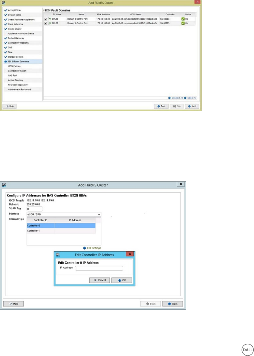
Figure 23. Add FluidFS Cluster Wizard — Select iSCSI Fault Domains
Steps
1. Select a Storage Center iSCSI control port for each connected subnet (Storage Center fault domain).
2. Click Next.
The Congure IP Addresses for NAS Controller iSCSI HBAs page opens.
Congure IP Addresses for NAS Controller iSCSI HBAs
Use the Congure IP Addresses for NAS Controller iSCSI HBAs page to congure IP addresses for each iSCSI HBA.
About this task
Use this page of the Add FluidFS Cluster wizard to congure iSCSI HBA IP addresses.
Figure 24. Add FluidFS Cluster Wizard — Congure IP Addresses for NAS Controller iSCSI HBA Page
Steps
1. Congure iSCSI HBA IP addresses for the rst iSCSI subnet (Storage Center fault domain).
36 Congure the FluidFS Cluster
a. Next to iSCSI Targets, locate the Storage Center iSCSI target IP addresses.
b. Based on these IP addresses, identify the iSCSI subnet (Storage Center fault domain).
c. In the VLAN Tag eld, type the VLAN ID for the subnet (fault domain).
d. From the Interface drop-down menu, select the controller interface that is connected to the iSCSI subnet.
•eth30 / SAN is the upper right port in each controller.
•eth31 / SAN b is the lower right port in each controller.
e. Dene an IP address for each controller by selecting the controller, clicking Edit Settings, and typing an IP address in the
dialog box.
f. Click Next.
The wizard displays connected Storage Center iSCSI target IP addresses for the second iSCSI subnet and automatically
selects the uncongured interface from the Interface drop-down menu.
2. Congure iSCSI HBA IP addresses for the second iSCSI subnet (Storage Center fault domain).
a. Next to iSCSI Targets, locate the Storage Center iSCSI target IP addresses.
b. Based on these IP addresses, identify the iSCSI subnet (Storage Center fault domain).
c. In the VLAN Tag eld, type the VLAN ID for the subnet (fault domain).
d. Dene an IP address for each controller by selecting the controller, click Edit Settings, and type an IP address in the dialog
box.
e. Click Next. The iSCSI ports are congured and the Connectivity Report page opens.
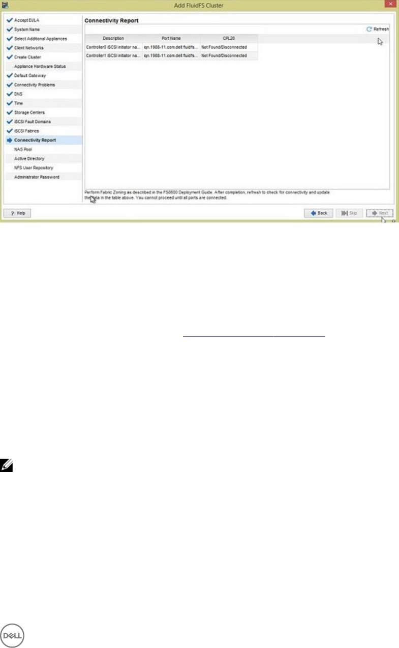
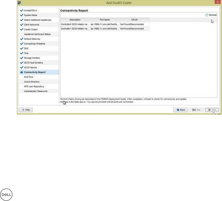
Connectivity Report (iSCSI)
Use the Connectivity Report page to verify iSCSI connectivity between the FluidFS cluster and the Storage Centers.
1. Use the report to verify iSCSI connectivity.
• When the Connectivity Report initially opens, iSCSI logins might still be occurring in the background, causing some or all of
the FluidFS cluster iSCSI initiators to show the status as Not Found/Disconnected. If this status is displayed, wait 30
seconds, then click Refresh to update the report.
Figure 25. Add FluidFS Cluster Wizard — Connectivity Report (Not Found/Disconnected)
• When the iSCSI logins are complete and the report has been refreshed, the status for each FluidFS cluster initiator shows as
Up.
Congure the FluidFS Cluster 37
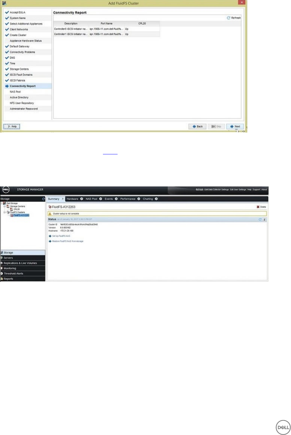
Figure 26. Add FluidFS Cluster Wizard — Connectivity Report (Up)
2. If the iSCSI conguration is correct, proceed to step 3. Otherwise, perform the following steps to modify the iSCSI
conguration. After you are past the Connectivity Report page, you will no longer be able to modify the iSCSI conguration
using the Add FluidFS Cluster wizard.
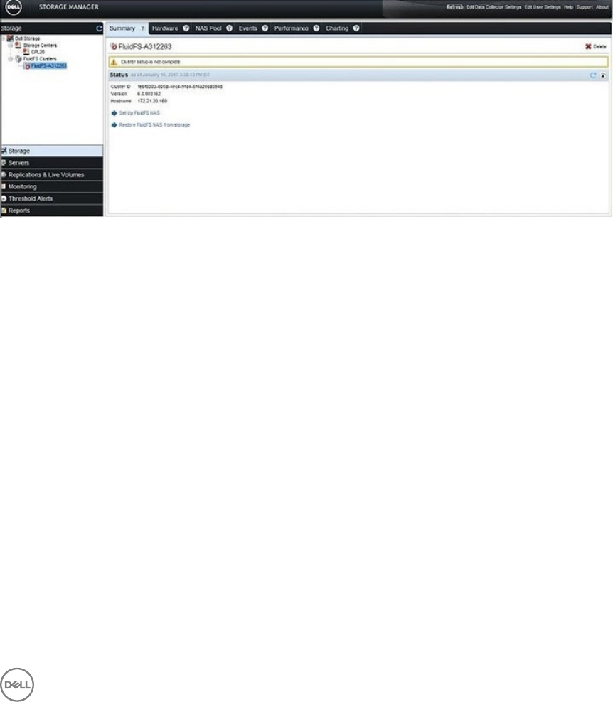
a. Close the Add FluidFS Cluster wizard by clicking the Close (x) button in the top-right corner of the wizard. The Summary
tab is displayed.
Figure 27. Cluster Setup Not Complete
b. Click Next. The Existing iSCSI Conguration page opens.
38 Congure the FluidFS Cluster
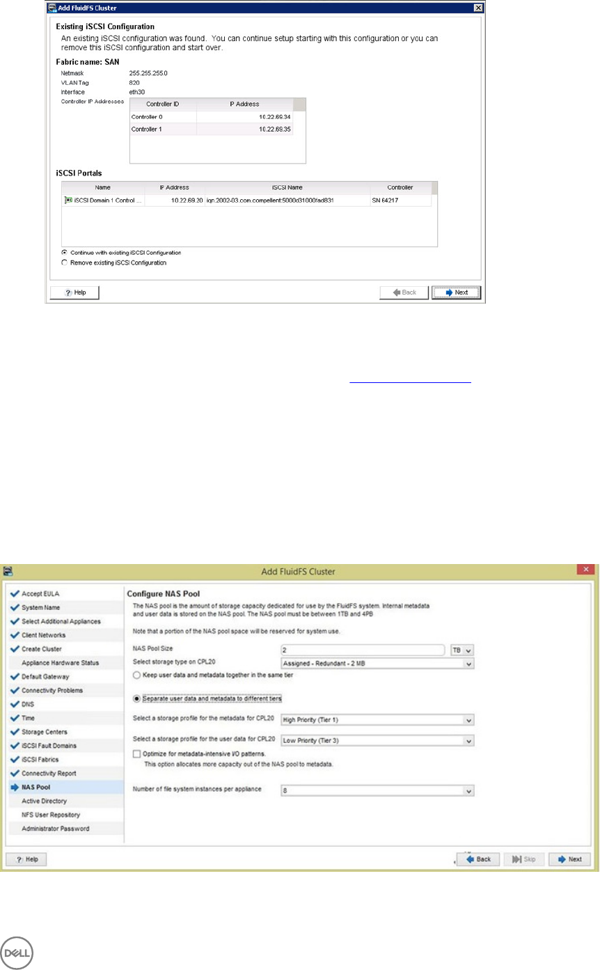
Figure 28. Add FluidFS Cluster Wizard — Existing iSCSI Conguration Page
c. Select Remove existing iSCSI Conguration.
d. Click Next. The Select Storage Centers page opens. See Select Storage Centers.
3. Click Next.
The Congure NAS Pool page opens.
Finalize FluidFS Cluster Conguration
Dene the NAS pool size, congure optional external directory service integration, and change the administrator password.
Congure the NAS Pool
Use the Congure NAS Pool page to specify the amount of block storage available for NAS volumes.
About this task
Use this page of the Add FluidFS Cluster wizard to congure the size of the NAS pool.
Figure 29. Add FluidFS Cluster Wizard — Congure NAS Pool
Congure the FluidFS Cluster 39
Steps
1. In the NAS Pool Size eld, type the amount of block storage to provide for NAS volumes in gigabytes (GB) or terabytes (TB).
The minimum NAS pool size is 1 TB. For information about maximum NAS pool sizes, see the Dell Fluid File System Version 6.0
Support Matrix.
NOTE:
• The usable FluidFS NAS pool is smaller due to FluidFS overhead. For example, if a single appliance cluster with a 2-TB
pool is created, the actual NAS pool size is about 1.6 TB (roughly 400-GB overhead).
• While the Storage Center supports thin provisioning, Dell strongly recommends avoiding over-provisioning of the NAS
pool. Size the NAS pool to be smaller than the available physical capacity of the Storage Center while keeping in mind
the RAID overhead. This way, if the NAS pool becomes full, the Storage Center will not run into emergency mode and
impact service availability. The NAS pool can be expanded later when more physical capacity is added to the Storage
Center.
Also, given that FluidFS itself supports thin-provisioning with the NAS cluster, you can size the NAS volumes so that
the total allocated NAS volume capacity is larger than the size of the NAS pool. This method of over-provisioning is
much safer than over-provisioning the NAS Pool itself.
• The Compellent volumes behind the FluidFS NAS Pool use the same page size as the selected page pool. Dell strongly
recommends using the 2MB page size for the NAS pool. If a page pool with 512KB page size is selected, you will not
be able to change it to 2MB after the NAS pool is created.
2. Select a storage type from the drop-down menu.
3. Enable or disable metadata tiering.
Metadata tiering provides the ability to store data and metadata in dierent storage tiers. Enable the radio button to optimize
the setting for metadata-intensive I/O patterns, which allocates a larger portion of the NAS pool for metadata than the non-
optimized setting.
NOTE:
• To use Metadata tiering, you must have an even number of Storage Centers.
• The default number of le system domains is suitable for the vast majority of situations, and cannot be reverted if it is
changed. Do not change the Number of System Instances Per Appliance eld without consulting Dell-EMC support.
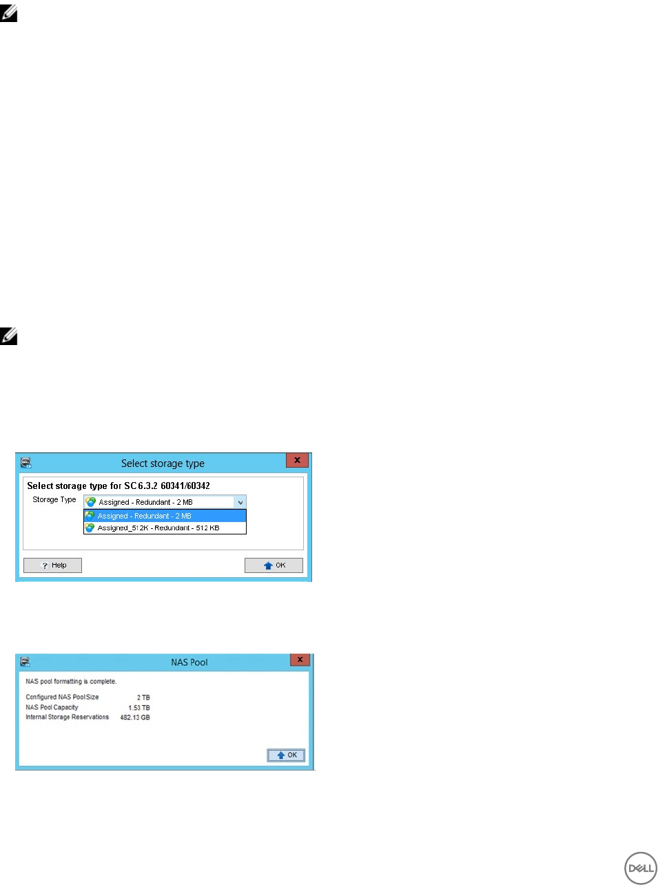
4. Click Next to provision and format the cluster.
• If multiple storage types are congured on a Storage Center, the Select storage type dialog box opens. Select a storage
type to provide storage for the NAS pool from the Storage Type drop-down menu, then click OK.
Figure 30. Select Storage Type Dialog Box
• Dell Storage Manager starts provisioning storage. Pages open to indicate the provisioning and formatting process. When the
process is complete, the NAS Pool dialog box opens.
Figure 31. NAS Pool Dialog Box
5. Click OK.
40 Congure the FluidFS Cluster
• If you did not close the Add FluidFS Cluster wizard while adding the FluidFS cluster, the Join Active Directory Domain
page opens. See Join the Active Directory Domain.
• If you closed and reopened the Add FluidFS Cluster wizard while adding the FluidFS cluster, the Change Administrator
Password page opens. See Change the Administrator Password. The Active Directory and NIS/LDAP pages of the wizard
are not displayed. The Active Directory and NIS/LDAP settings must be congured as a post-setup task.
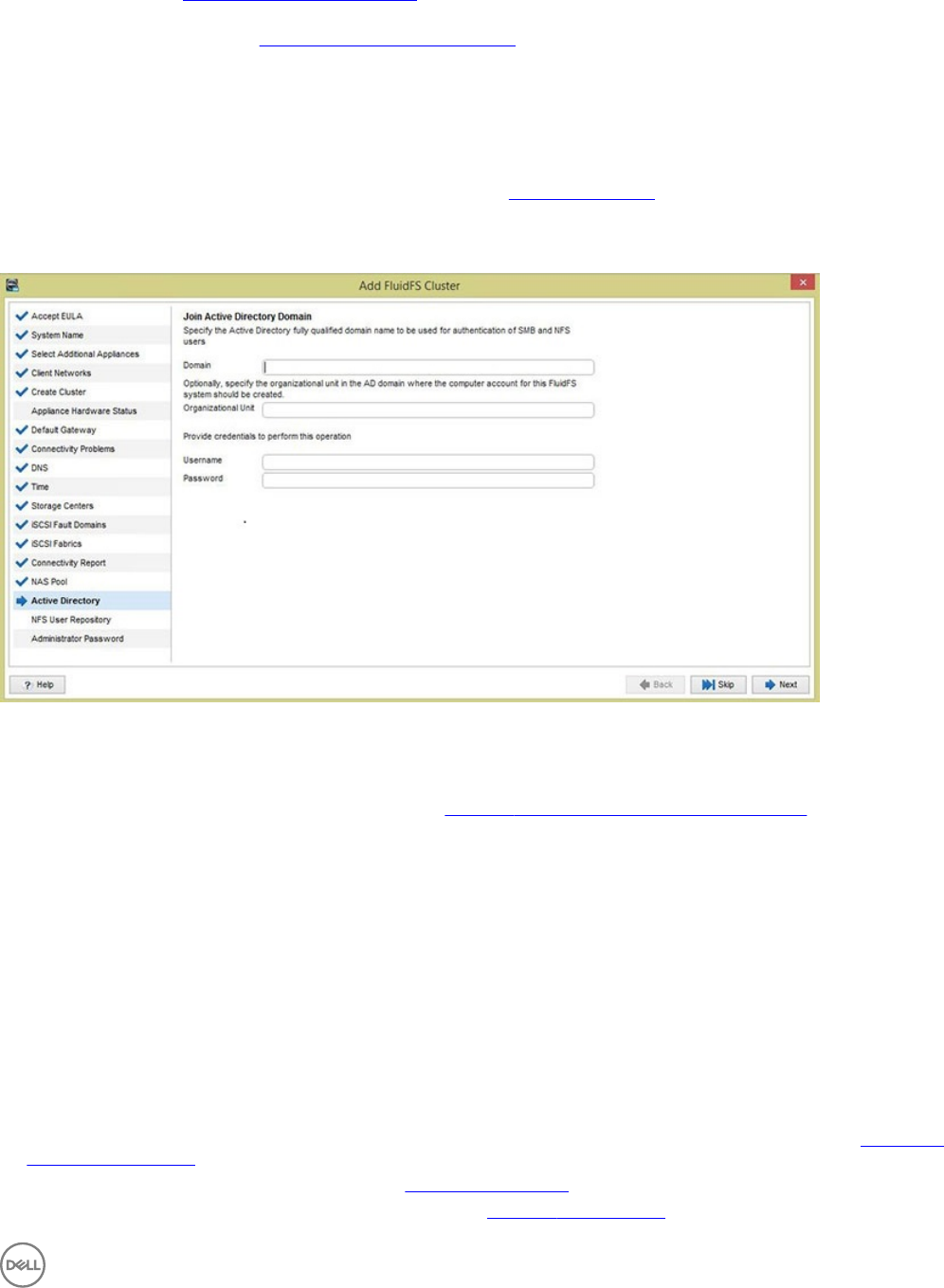
Join the Active Directory Domain
In environments that use Active Directory, the FluidFS cluster can join the Active Directory domain and authenticate clients using
Active Directory for access to SMB shares.
Prerequisites
You must have Active Directory credentials with specic privileges. See Network Credentials.
About this task
Adding multiple Active Directory servers ensures continued authentication of clients in the event of a resource outage. If the FluidFS
cluster cannot establish contact with a server, it attempts to connect to the remaining servers.
Figure 32. Add FluidFS Cluster Wizard — Join Active Directory Domain
Steps
1. (Optional) Skip Active Directory conguration by clicking Next.
The Congure External User Database page opens. See Congure the External User Database (NIS_LDAP).
2. In the Domain eld, type the Active Directory domain.
3. (Optional) Specify the organizational unit in the AD domain where the computer account for the FluidFS system should be
created.
4. (Optional) Type the organizational unit in the Organizational Unit eld.
5. In the Username eld, type an Active Directory account name that has the necessary privileges.
6. In the Password eld, type the Active Directory account password.
7. Click Next.
The Congure External User Database page opens.
Congure the External User Database (NIS_LDAP)
FluidFS clusters can authenticate client access to NFS exports with Network Information Service (NIS) or Lightweight Directory
Access Protocol (LDAP).
• To skip external authentication, select None, then click Next. The Change Administrator Password page opens. See Change the
Administrator Password.
• To use Network Information Service, select NIS. See Congure NIS Settings.
• To use Lightweight Directory Access Protocol, select LDAP. See Congure LDAP Settings.
Congure the FluidFS Cluster 41
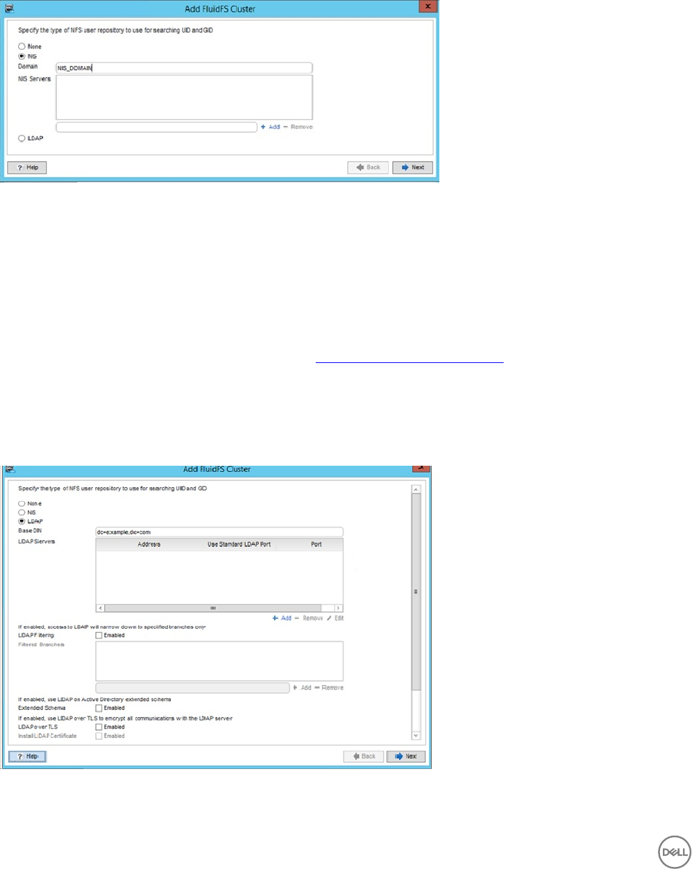
Congure NIS Settings
Adding multiple NIS servers ensures continued authentication of clients in the event of a resource outage. If the FluidFS cluster
cannot establish contact with a server, it attempts to connect to the remaining servers.
About this task
Use this page of the Add FluidFS Cluster wizard to congure external authentication.
Figure 33. Add FluidFS Cluster Wizard — Congure External User Database Page
Steps
1. In the NIS Domain Name eld, type an NIS domain name.
2. In the NIS Servers area, dene one or more NIS servers.
• To dene an NIS server, type the server host name or IP address in the eld, then click Add.
• To remove an NIS server, select the server, then click Remove.
• To increase or decrease the order of preference for an NIS server, select the server, then click Up or Down.
3. Click Next.
The Change Administrator Password page opens. See Change the Administrator Password.
Congure LDAP Settings
In environments that use Lightweight Directory Access Protocol (LDAP), a FluidFS cluster can authenticate UNIX/Linux clients using
LDAP for access to NFS exports. The LDAP database can be provided by either an LDAP server or Active Directory.
About this task
Use this page of the Add FluidFS Cluster wizard to congure external authentication.
Figure 34. Add FluidFS Cluster Wizard — Congure External User Database Page
FluidFS clusters support the following LDAP congurations:
42 Congure the FluidFS Cluster
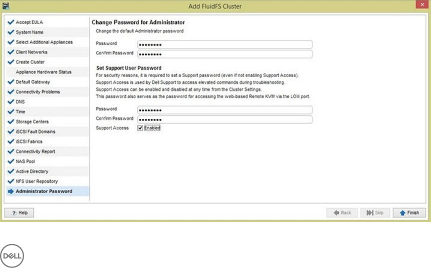
• Anonymous LDAP – The connection from the FluidFS cluster to the LDAP servers is not authenticated. The data is sent in plain
text.
• Authenticated LDAP – The connection from the FluidFS cluster to the LDAP servers is authenticated using a user name and
password. The data is sent in plain text.
• LDAP over TLS/SSL – The connection from the FluidFS cluster to the LDAP servers is authenticated and encrypted. To validate
the certicate used by the LDAP server, you must export the SSL certicate from the LDAP server and upload it to the FluidFS
cluster.
Adding multiple LDAP servers ensures continued authentication of clients in the event of a resource outage. If the FluidFS cluster
cannot establish contact with a server, it attempts to connect to the remaining servers.
Steps
1. In the Base DN eld, type an LDAP base distinguished name to represent where in the directory to begin searching for users.
The name is usually in the format: dc=domain,dc=com.
2. In the LDAP Servers text eld, type the host name or IP address of an LDAP server and click Add. Repeat this step for any
additional LDAP servers.
3. In the LDAP Servers area, dene one or more LDAP servers.
• To dene an LDAP server, type the server host name or IP address in the eld, then click Add.
• To remove an LDAP server, select the server, then click Remove.
• To increase or decrease the order of preference for an LDAP server, select the server, then click Up or Down.
4. (Optional) Congure the remaining LDAP attributes as needed. These options are described in the online help.
• To indicate that Active Directory provides the LDAP database, select the Use LDAP on Active Directory Extended Schema
checkbox.
• To authenticate the connection from the FluidFS cluster to the LDAP server, select the Use Non-Anonymous LDAP bind
checkbox. Then, type the LDAP bind distinguished name used to authenticate the connection in the Bind DN eld and type
the LDAP bind password in the Bind Password eld.
• To encrypt the connection from the FluidFS cluster to the LDAP server using TLS, select the Use TLS over LDAP
checkbox.
• To validate the certicate used by the LDAP server, select the Install LDAP Certicate checkbox. Then, click Upload
Certicate and select the LDAP SSL certicate to upload to the FluidFS cluster.
5. Click Next.
The Change Administrator Password page opens.
Change the Administrator Password
Change the default Administrator password for the FluidFS cluster.
About this task
Use this page of the Add FluidFS Cluster wizard to change the default password of the Administrator account.
Figure 35. Change Password for Administrator Page
Congure the FluidFS Cluster 43
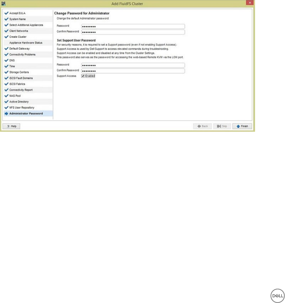
Steps
1. To change the default Administrator password, type a password for the Administrator account in the Password eld.
2. In the Conrm Password eld, retype the password.
3. To set a Support User password, type a password in the Password eld.
4. In the Conrm Password eld, retype the password.
5. Select or deselect the Support Access Enabled checkbox.
6. Click Finish.
The FluidFS cluster is added to Dell Storage Manager and displayed on the Storage view.
Set Support User Password
Use the this page to set the support user password.
Click Setup FluidFS NAS to reenter the Add FluidFS Cluster wizard. The Set Support User Password page opens. The
support account is used by Dell Technical Support to perform remote troubleshooting. A password must be set for the support
account even if it is disabled.
Figure 36. Add FluidFS Cluster Wizard — Set Support User Password Page
a. In the Password eld, type a password for the support account.
b. In the Conrm Password eld, retype the password.
c. (Optional) Select the Support Access checkbox to enable the support account.
Remove a FluidFS Cluster From Dell Storage Manager
Remove a FluidFS cluster if you no longer want to manage it using Dell Storage Manager. For example, you might want to move the
FluidFS cluster to another Dell Storage Manager Data Collector.
1. Click the Storage view and select a FluidFS cluster.
2. Click the File System tab.
3. In the right pane, click Delete to open the dialog box.
4. Click OK.
44 Congure the FluidFS Cluster
5
Perform Post-Setup Tasks
Complete the deployment by performing these post-setup tasks. All tasks are optional.
Add DNS Records for the FluidFS Cluster
If clients access the FluidFS cluster by name, add an entry in the DNS server that associates the FluidFS cluster name to the FluidFS
cluster client VIPs.
• If you are in a routed client network and using multiple client VIPs, add all client VIPs to the DNS server and associate them with
the same FluidFS cluster name (set up round-robin DNS).
• If you are using Active Directory, the DNS servers must be the same DNS servers that the Active Directory domain controllers
use.
Enabling Secured Management
By default, all FluidFS cluster management ports are open on all subnets, along with the other ports needed for client access (SMB/
NFS), replication, and NDMP. Secured management, when enabled, exclusively limits all management trac to one specic subnet.
The subnet on which secured management is enabled also has the necessary ports open for client access, replication, and NDMP
trac. Other subnets will not have any of the management ports listening on them, making them available only for client access,
replication, and NDMP trac. This restriction prevents users on client (data) access subnets from accessing any FluidFS cluster
management functions.
In FluidFS, the ports listed in the following table do not participate in SMB/NFS communication, but are exposed on the client
network by default. Enabling secured management allows you to expose the management ports on a management subnet only.
Service Port
Web Services 80
Secure Web Services 443
FTP 44421
FTP (Passive) 44430–44439
FTPS 990
SSH 22
Dell Storage Manager communication 35451
Secured management can be enabled only after the system is deployed. To make a subnet secure:
• The subnet must exist prior to enabling the secured management feature.
• The subnet can reside on the client network (subnet-level isolation of management trac) or the LOM (Lights Out
Management) Ethernet port (physical isolation of management trac). The LOM Ethernet port is located on the lower-right side
of the back panel of a NAS controller.
• You must log in from this subnet.
Perform Post-Setup Tasks 45

Add a Secured Management Subnet
The subnet on which you enable secured management must exist prior to enabling the secured management feature.
1. In the Storage view, select a FluidFS cluster.
2. Click the File System tab.
3. In the File System view, select Cluster Connectivity, and then click the Management Network tab.
4. In the Management Network panel, click Edit Settings.
The Modify Administrative Network dialog box opens.
5. From the State drop-down list, select a state to be used for the management network.
• Select Restricted for management functionality to be blocked on other subnets
• Select Unrestricted for management functionality to be available on all subnets.
6. To change the prex of the network, type a prex length in the Prex eld.
7. In the Network ID eld, type the ID for the network that you want to modify.
8. Add one or more management VIPs through which the administrator manages the FluidFS cluster.
a. In the Virtual IP eld, type a management virtual IP address.
b. In the box for the Controller IP Address eld, type a controller IP address and click Add. Repeat this step for each
controller.
9. To specify a VLAN tag, type a VLAN tag in the VLAN Tag eld. When a VLAN spans multiple switches, the VLAN tag is used to
specify which ports and interfaces to send broadcast packets to.
10. From the Interface drop-down list, select the interface on which the secured management subnet is located.
• Select Admin to use the LOM Ethernet port for physical isolation of management trac. You must also connect a network
cable to the LOM Ethernet port of each controller in the rst (or only) appliance.
• Select Client for subnet-level isolation of management trac.
11. Click OK.
Enable or Disable Secured Management
Enable secured management to exclusively limit management trac to one specic subnet.
Prerequisites
• The subnet on which you enable secured management must exist before you enable the secured management feature.
• The FluidFS cluster must be managed by Storage Manager using the subnet on which secured management will be enabled. To
manage the FluidFS cluster on the secured management subnet, remove the FluidFS cluster from Storage Manager and then re-
add the FluidFS cluster to Storage Manager using the secured management subnet management VIP.
About this task
After enabling secured management, if you are connected to Storage Manager through the secured management subnet, your
management session is temporarily interrupted while the change takes eect. During this time, the following message is displayed in
Storage Manager:
Communication with the cluster was interrupted in process of issuing a command that performs
modification to the cluster.
After the change takes eect, your management session will resume automatically. Management sessions on all other subnets are
disconnected.
Disable secured management to allow management trac from any subnet.
Steps
1. In the Storage view, select a FluidFS cluster.
2. Click the File System tab.
3. In the File System view, select Cluster Connectivity and then click the Management Network tab.
4. In the Management Network panel, click Edit Settings.
46 Perform Post-Setup Tasks
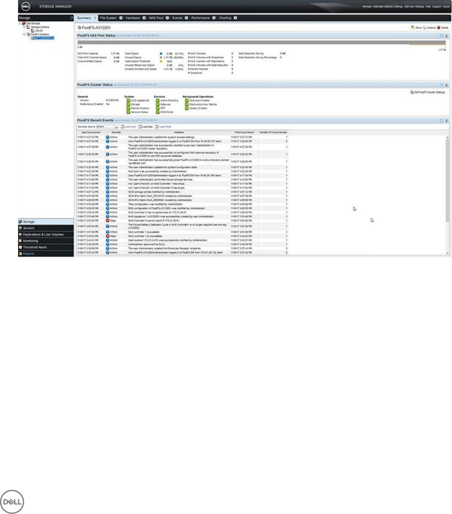
The Modify Administrative Network dialog box opens.
5. Enable or disable secured management.
From the State drop-down list:
• To enable secured management, select Restricted or Unrestricted.
• To disable secured management, select Disabled.
6. Click OK.
Verify That Dell Storage Manager Is Receiving FluidFS Events
FluidFS errors and operations are reported to the Dell Storage Manager Client. Verify that errors and activities are being reported.
1. Use the Dell Storage Manager Client to connect to the Data Collector and log in.
2. In the Storage pane, select a FluidFS cluster.
3. Click the Summary tab. Events are displayed under FluidFS Cluster Events.
Figure 37. FluidFS Events
Next Steps
After deployment is complete, perform additional tasks to congure the FluidFS cluster for the network environment. These tasks
depend on the conguration, so some might not apply to your site.
See the Dell Storage Manager Administrator’s Guide for detailed conguration instructions, including how to:
•Congure Active Directory and NIS/LDAP (if skipped in the Add FluidFS Cluster wizard)
•Congure multitenancy (disabled by default, enable if desired)
• Create NAS volumes
• Create network shares
• Create quota rules
•Congure antivirus scanning
• Create snapshot schedules
•Congure NDMP backups
Perform Post-Setup Tasks 47

•Congure replication to a remote FluidFS cluster
48 Perform Post-Setup Tasks

A
Upgrade an Appliance to the Latest FluidFS 6.0
Version
If an FS8600 appliance was imaged with FluidFS v5.0 or an early version of FluidFS v6.0 at the factory and will be deployed running
FluidFS v6.0, upgrade the standby controllers to the latest version before conguring them as part of a FluidFS v6.0 cluster.
NOTE: This procedure does not update the internal USB drive in the FS8600 controllers.
Upgrade Prerequisites
Make sure the following prerequisites are met before beginning the upgrade procedure.
■Prerequisite
□Both controllers in the FS8600 appliance must be powered on in standby mode.
□You must have the following materials:
• FluidFS 6.0 service pack ISO le
• USB ash drive with at least 4 GB of free space to hold the service pack le
• USB keyboard and VGA monitor
Upgrade Standby Controllers to the Latest Version of FluidFS v6.0
About this task
NOTE: FS8600 controllers are shipping from the factory pre-imaged with FluidFS 6.0, so it is unlikely that you will
encounter a standby controller running FluidFS 5.0. Therefore, the procedure provided in this section will rarely be used.
The only time this procedure is needed is if a replacement controller was ordered to replace a faulty controller before
deployment.
Steps
1. Connect KVM to controller 0 and log in.
a. Connect a KVM device to controller 0. This controller is on the left when you are looking from the back.
b. Type cli at the login as prompt.
c. Type Administrator at the login as prompt.
d. Type Stor@ge! at the password prompt.
You are logged in to the CLI.
2. Congure FTP on controller 0.
a. Congure a network subnet.
CLI> environment network subnets add 24 -PrivateIPs 192.168.1.10,192.168.1.11
NOTE: The subnet will be wiped away by the FluidFS upgrade and must be recongured at the start of
deployment.
b. Enable FTP.
CLI> maintenance support security FTP configuration enable
3. Upload the new ISO image via FTP.
a. Connect to FluidFS FTP server on controller 0 using the IP address of the controller, not the VIP.
ftp://Administrator@192.168.1.10:44421/servicepack. Type Stor@ge when a dialog box opens asking for credentials.
Upgrade an Appliance to the Latest FluidFS 6.0 Version 49

b. Copy the DellFluidFS-6.0.xxyyyy.iso le to the servicepack folder.
4. Flash the controller to the new version:
a. Wait for about 10 minutes until the new FluidFS version shows up as Not installed in the following list:
CLI> maintenance software-updates list
b. Initiate the upgrade using the following CLI command:
CLI> maintenance software-updates flash-standby-controller lename
5. Wait for up to 30 minutes until the controller is up and running again. Several automatic reboots might occur during the standby
upgrade process. Do not disturb the controller until the login prompt reappears. At that point, the controller has been reimaged
and any previous settings (such as network settings and FTP settings) have been erased.
NOTE: In step 2, you can also use a laptop to connect to the LOM port on controller 0 and transfer the service pack via
FTP. Replace step 2a with the following command to congure the LOM port:
CLI> environment network management access subnet edit -State Restricted -Interface Admin -
PrefixLength 24 -PrivateIPs 192.168.1.10,192.168.1.11 -PublicIPs 192.168.1.100
50 Upgrade an Appliance to the Latest FluidFS 6.0 Version
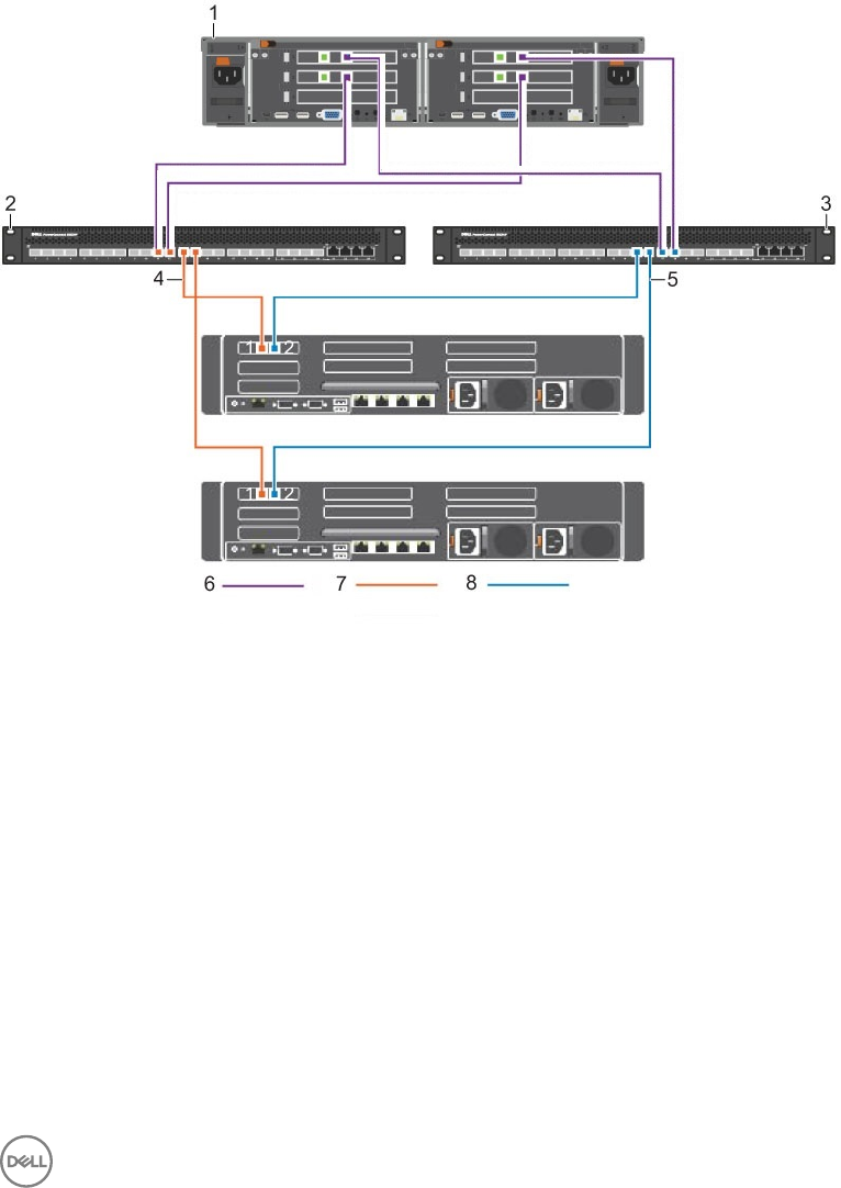
B
iSCSI Switch Conguration Examples
These examples shows how to congure the switch that is used to connect a 10GbE iSCSI appliance to the SAN/internal network.
Dell PowerConnect iSCSI Switch Conguration
This example shows how to cable and congure a Dell PowerConnect 8024F switch to connect an FS8600 10GbE iSCSI appliance to
the SAN/internal network. This example uses the best-practices conguration, which includes dual switches and dual iSCSI SANs.
Figure 38. Dell PowerConnect 8024F iSCSI Switch and FS8600 10GbE iSCSI Appliance Conguration
1. FS8600 10GbE iSCSI 2. PC8024–SAN-B
3. PC8024–SAN-A 4. VLAN 119 for SAN B
5. VLAN 118 for SAN A 6. Untagged VLAN — FS8600 Internal
7. VLAN FS8600 SAN A 8. VLAN FS8600 SAN B
iSCSI Switch Conguration Examples 51
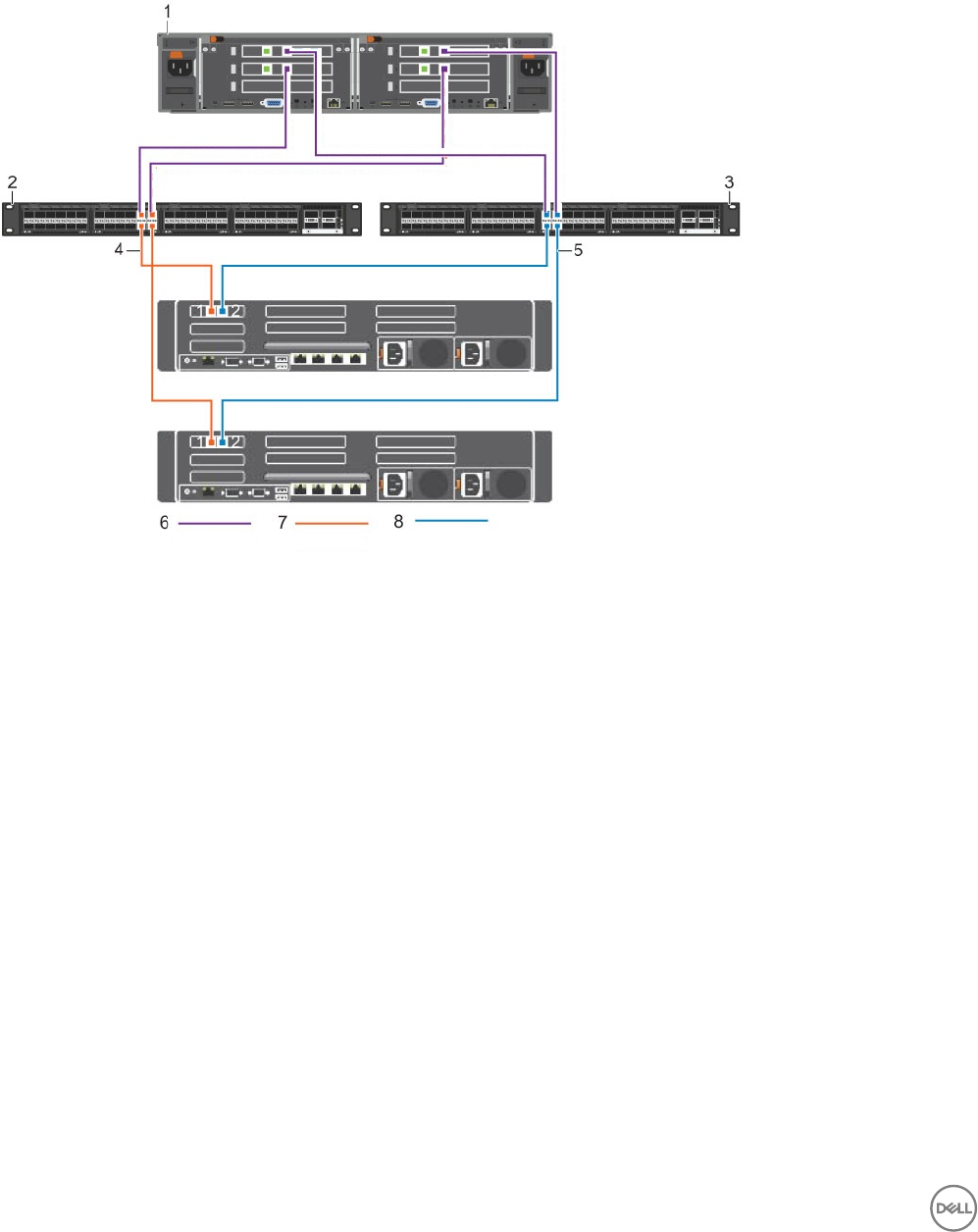
Dell Force10 S5000 iSCSI Switch Conguration
This example shows how to cable and congure a Dell Force10 S5000 switch to connect an FS8600 10GbE iSCSI appliance to the
SAN/internal network. This example uses the best-practices conguration, which includes dual switches and dual iSCSI SANs.
Figure 39. Dell Force10 S5000 Switch and FS8600 10GbE iSCSI Appliance Conguration
1. FS8600 10GbE iSCSI 2. F10 S5000–SAN-A
3. F10 S5000–SAN-B 4. VLAN 30 for SAN A
5. VLAN 31 for SAN B 6. Untagged VLAN — FS8600 Internal
7. VLAN FS8600 SAN A 8. VLAN FS8600 SAN B
52 iSCSI Switch Conguration Examples
