Dell Poweredge C6300 C6320 Owner's Manual User Power Edge En Us
poweredge-c6300 Dell PowerEdge C6320 Owner's Manual poweredge-c6320_owners-manual_en-us
User Manual: Dell poweredge-c6300 Dell PowerEdge C6320 Owner's Manual
Open the PDF directly: View PDF ![]() .
.
Page Count: 169 [warning: Documents this large are best viewed by clicking the View PDF Link!]
- Dell PowerEdge C6320 Owner's Manual
- Dell PowerEdge C6320 product overview
- Supported configurations for PowerEdge C6320 system
- Accessing system features during startup
- Front panel features and indicators
- Hard drive indicator patterns
- Back panel features and indicators
- LAN indicator codes
- Power and system board indicator codes
- Power Supply Unit indicator codes
- Baseboard Management Controller (BMC) heart beat LED
- System configuration limitations by Intel Xeon processor E5-2600 v3 and E5-2600 v4 product family
- Locating your system Service Tag
- Documentation resources
- Technical specifications
- Initial system setup and configuration
- Pre-operating system management applications
- Installing and removing system components
- Safety instructions
- Before working inside your system
- After working inside your system
- Recommended tools
- System cover
- Inside the system
- Cooling fans
- Hard drives
- Removing a 3.5-inch hard drive blank
- Installing a 3.5-inch hard drive blank
- Removing a 2.5-inch hard drive blank
- Installing a 2.5-inch hard drive blank
- Removing a hard drive
- Installing a hard drive
- Removing a hard drive from a hard drive carrier
- Installing a hard drive into a hard drive carrier
- Installing a 2.5-inch SSD into a 3.5-inch hard drive carrier
- SSD and SSD holder
- SATADOM
- Power supply units
- System board tray
- System board assembly
- Cooling shroud
- Heat sinks
- Processors
- Expansion card assembly and expansion card
- PCI-E slot priority
- PERC cards
- Riser card
- Optional mezzanine cards
- Mezzanine card bridge board
- System memory
- System battery
- System board
- Trusted Platform Module
- Power distribution boards
- Midplanes
- Hard drive backplanes
- 2.5-inch hard drive expander configuration
- Control panel
- Sensor boards
- Removing the sensor board for 3.5-inch hard drive system
- Installing the sensor board for 3.5-inch hard drive system
- Cable routing for sensor board and control panel for 3.5-inch hard drive system
- Removing the sensor board for 2.5-inch hard drive system
- Installing the sensor board for 2.5-inch hard drive system
- Cable routing for sensor board and control panel for 2.5-inch hard drive system
- Jumpers and connectors
- Troubleshooting your system
- Safety first — for you and your system
- Installation Problems
- Minimum configuration to POST
- Troubleshooting system startup failure
- Troubleshooting external connections
- Troubleshooting the video subsystem
- Troubleshooting a USB device
- Troubleshooting a serial I/O device
- Troubleshooting a NIC
- Troubleshooting a wet system
- Troubleshooting a damaged system
- Troubleshooting the system battery
- Troubleshooting power supply units
- Troubleshooting cooling problems
- Troubleshooting cooling fans
- Troubleshooting system memory
- Troubleshooting a hard drive
- Troubleshooting a storage controller
- Troubleshooting expansion cards
- Troubleshooting processors
- Getting help

Dell PowerEdge C6320
Owner's Manual
Regulatory Model: B08S
Regulatory Type: B08S003

Notes, cautions, and warnings
NOTE: A NOTE indicates important information that helps you make better use of your computer.
CAUTION: A CAUTION indicates either potential damage to hardware or loss of data and tells you how to avoid the problem.
WARNING: A WARNING indicates a potential for property damage, personal injury, or death.
Copyright © 2017 Dell Inc. or its subsidiaries. All rights reserved. Dell, EMC, and other trademarks are trademarks of Dell Inc. or its subsidiaries. Other
trademarks may be trademarks of their respective owners.
2017 - 08
Rev. A04

Contents
1 Dell PowerEdge C6320 product overview.......................................................................................................8
Supported congurations for PowerEdge C6320 system............................................................................................ 8
Accessing system features during startup......................................................................................................................9
Front panel features and indicators................................................................................................................................10
Hard drive indicator patterns........................................................................................................................................... 11
Back panel features and indicators.................................................................................................................................13
LAN indicator codes......................................................................................................................................................... 14
Power and system board indicator codes......................................................................................................................15
Power Supply Unit indicator codes................................................................................................................................ 16
1400 W AC/1400 W HVDC PSUs.............................................................................................................................16
1600 W AC/1600 W HVDC PSU...............................................................................................................................17
Baseboard Management Controller (BMC) heart beat LED.......................................................................................18
System conguration limitations by Intel Xeon processor E5-2600 v3 and E5-2600 v4 product family ............. 18
Locating your system Service Tag................................................................................................................................. 22
2 Documentation resources............................................................................................................................ 24
3 Technical specications............................................................................................................................... 26
Chassis dimensions..........................................................................................................................................................26
Processor specications..................................................................................................................................................27
PSU specications........................................................................................................................................................... 27
System battery specications ....................................................................................................................................... 27
Memory specications ................................................................................................................................................... 27
Environmental specications .........................................................................................................................................28
4 Initial system setup and conguration..........................................................................................................30
Setting up your system................................................................................................................................................... 30
iDRAC conguration........................................................................................................................................................ 30
Options to set up iDRAC IP address........................................................................................................................30
Options to install the operating system..........................................................................................................................31
Methods to download rmware and drivers............................................................................................................31
5 Pre-operating system management applications..........................................................................................33
Options to manage the pre-operating system applications........................................................................................ 33
System Setup................................................................................................................................................................... 33
Viewing System Setup.............................................................................................................................................. 33
System Setup details.................................................................................................................................................34
System BIOS...............................................................................................................................................................34
iDRAC Settings utility................................................................................................................................................ 54
Device Settings.......................................................................................................................................................... 55
Dell Lifecycle Controller...................................................................................................................................................55
Embedded system management............................................................................................................................. 55
Contents 3

Boot Manager.................................................................................................................................................................. 55
Viewing Boot Manager..............................................................................................................................................55
Boot Manager main menu........................................................................................................................................ 56
PXE boot...........................................................................................................................................................................56
6 Installing and removing system components................................................................................................ 57
Safety instructions........................................................................................................................................................... 57
Before working inside your system................................................................................................................................ 57
After working inside your system...................................................................................................................................58
Recommended tools........................................................................................................................................................58
System cover....................................................................................................................................................................58
Removing the system cover.....................................................................................................................................58
Installing the system cover....................................................................................................................................... 59
Inside the system............................................................................................................................................................. 60
Cooling fans......................................................................................................................................................................60
Removing a cooling fan.............................................................................................................................................60
Installing a cooling fan............................................................................................................................................... 62
Hard drives........................................................................................................................................................................63
Removing a 3.5-inch hard drive blank..................................................................................................................... 63
Installing a 3.5-inch hard drive blank........................................................................................................................64
Removing a 2.5-inch hard drive blank..................................................................................................................... 64
Installing a 2.5-inch hard drive blank....................................................................................................................... 65
Removing a hard drive...............................................................................................................................................66
Installing a hard drive.................................................................................................................................................66
Removing a hard drive from a hard drive carrier....................................................................................................67
Installing a hard drive into a hard drive carrier........................................................................................................68
Installing a 2.5-inch SSD into a 3.5-inch hard drive carrier...................................................................................68
SSD and SSD holder........................................................................................................................................................70
Removing the SSD and SSD Holder........................................................................................................................70
Installing the SSD and SSD holder........................................................................................................................... 72
DC to DC board.......................................................................................................................................................... 73
Cable routings for SSD and DC to DC board and LSI 2008..................................................................................74
SATADOM.........................................................................................................................................................................75
Removing the SATADOM..........................................................................................................................................75
Installing the SATADOM............................................................................................................................................ 76
Cable routing for SATADOM and LSI 2008.............................................................................................................77
Power supply units........................................................................................................................................................... 77
Removing a power supply unit................................................................................................................................. 78
Installing a power supply unit....................................................................................................................................79
System board tray............................................................................................................................................................79
Removing the system board tray ............................................................................................................................ 79
Installing the system board tray .............................................................................................................................. 80
System board assembly................................................................................................................................................... 81
Removing the system board assembly ....................................................................................................................81
Installing the system board assembly ......................................................................................................................81
Cooling shroud..................................................................................................................................................................82
4Contents

Removing the cooling shroud ..................................................................................................................................82
Installing the cooling shroud .................................................................................................................................... 83
Heat sinks......................................................................................................................................................................... 84
Removing the heat sink ............................................................................................................................................84
Installing the heat sink ..............................................................................................................................................85
Processors ....................................................................................................................................................................... 86
Removing a processor ..............................................................................................................................................86
Installing a processor ................................................................................................................................................ 87
Expansion card assembly and expansion card .............................................................................................................88
Removing the expansion card.................................................................................................................................. 88
Installing the expansion card.................................................................................................................................... 90
PCI-E slot priority ............................................................................................................................................................ 91
PERC cards....................................................................................................................................................................... 91
Removing the PERC card .........................................................................................................................................91
Installing the PERC card .......................................................................................................................................... 92
Riser card ......................................................................................................................................................................... 92
Optional riser cards....................................................................................................................................................92
Removing the riser card............................................................................................................................................ 93
Installing the riser card.............................................................................................................................................. 94
Optional mezzanine cards...............................................................................................................................................94
Removing the optional LSI 2008 SAS mezzanine card.........................................................................................95
Installing the optional LSI 2008 SAS mezzanine card .......................................................................................... 96
Cable routing for LSI 2008 SAS mezzanine card...................................................................................................96
Removing the 1GbE mezzanine card....................................................................................................................... 97
Installing the 1GbE mezzanine card ........................................................................................................................ 99
Removing the 10GbE mezzanine card ..................................................................................................................100
Installing the 10GbE mezzanine card .................................................................................................................... 102
Mezzanine card bridge board ...................................................................................................................................... 102
Removing the mezzanine card bridge board ....................................................................................................... 102
Installing the mezzanine card bridge board ..........................................................................................................103
System memory..............................................................................................................................................................104
Memory slot features ..............................................................................................................................................104
Supported memory module conguration ............................................................................................................104
Removing the memory modules ............................................................................................................................106
Installing the memory modules................................................................................................................................107
System battery............................................................................................................................................................... 108
Replacing the system battery ................................................................................................................................ 108
System board .................................................................................................................................................................109
Removing a system board ...................................................................................................................................... 109
Installing a system board ..........................................................................................................................................111
Cable routing for onboard SATA cables (1U node) ...............................................................................................112
Trusted Platform Module................................................................................................................................................113
Installing the Trusted Platform Module...................................................................................................................113
Initializing the TPM for BitLocker users..................................................................................................................114
Initializing the TPM for TXT users...........................................................................................................................114
Contents 5

Power distribution boards.............................................................................................................................................. 115
Removing the power distribution board 1...............................................................................................................115
Removing the power distribution board 2..............................................................................................................117
Installing the power distribution board 2................................................................................................................ 118
Installing the power distribution board 1.................................................................................................................119
Cable routing for the power distribution boards ..................................................................................................120
Midplanes......................................................................................................................................................................... 121
Removing the midplane........................................................................................................................................... 122
Installing the midplane..............................................................................................................................................125
Cable routing–midplane to the hard drive backplane ......................................................................................... 126
Cable routing for middle plane to 2.5-inch hard drive backplane for expander conguration .......................130
Hard drive backplanes.....................................................................................................................................................131
Removing the hard drive backplane.......................................................................................................................133
Installing the hard drive backplane......................................................................................................................... 135
2.5-inch hard drive expander conguration................................................................................................................ 136
Removing the 2.5-inch hard drive backplane for expander conguration.........................................................137
Installing the 2.5-inch hard drive backplane for expander conguration............................................................141
Control panel....................................................................................................................................................................141
Removing the control panel..................................................................................................................................... 141
Installing the control panel.......................................................................................................................................143
Sensor boards................................................................................................................................................................. 144
Removing the sensor board for 3.5-inch hard drive system............................................................................... 144
Installing the sensor board for 3.5-inch hard drive system................................................................................. 145
Cable routing for sensor board and control panel for 3.5-inch hard drive system........................................... 146
Removing the sensor board for 2.5-inch hard drive system............................................................................... 147
Installing the sensor board for 2.5-inch hard drive system................................................................................. 148
Cable routing for sensor board and control panel for 2.5-inch hard drive system........................................... 148
7 Jumpers and connectors ........................................................................................................................... 150
C6320 system board connectors................................................................................................................................. 150
LSI 2008 SAS mezzanine card connectors................................................................................................................. 152
Powerville dual port 1GbE .............................................................................................................................................153
Twinville dual port 10GbE ..............................................................................................................................................153
Power distribution board 1 connectors ....................................................................................................................... 154
Power distribution board 2 connectors ...................................................................................................................... 154
Sensor board connectors ............................................................................................................................................. 155
Jumper settings..............................................................................................................................................................155
System conguration jumper settings on the C6320 system board..................................................................155
Backplane jumper settings ..................................................................................................................................... 156
8 Troubleshooting your system...................................................................................................................... 157
Safety rst — for you and your system...................................................................................................................... 157
Installation Problems ..................................................................................................................................................... 157
Minimum conguration to POST .................................................................................................................................158
Troubleshooting system startup failure........................................................................................................................158
Troubleshooting external connections......................................................................................................................... 158
6Contents

Troubleshooting the video subsystem......................................................................................................................... 158
Troubleshooting a USB device......................................................................................................................................158
Troubleshooting a serial I/O device.............................................................................................................................. 159
Troubleshooting a NIC....................................................................................................................................................159
Troubleshooting a wet system...................................................................................................................................... 160
Troubleshooting a damaged system..............................................................................................................................161
Troubleshooting the system battery............................................................................................................................. 161
Troubleshooting power supply units.............................................................................................................................162
Troubleshooting power source problems...............................................................................................................162
Power supply unit problems.................................................................................................................................... 162
Troubleshooting cooling problems................................................................................................................................ 163
Troubleshooting cooling fans.........................................................................................................................................163
Troubleshooting system memory..................................................................................................................................164
Troubleshooting a hard drive.........................................................................................................................................165
Troubleshooting a storage controller............................................................................................................................165
Troubleshooting expansion cards................................................................................................................................. 166
Troubleshooting processors...........................................................................................................................................167
9 Getting help............................................................................................................................................... 168
Contacting Dell............................................................................................................................................................... 168
Documentation feedback.............................................................................................................................................. 168
Accessing system information by using QRL..............................................................................................................168
Quick Resource Locator for C6320............................................................................................................................. 169
Contents 7

Dell PowerEdge C6320 product overview
The Dell PowerEdge C6320 is an ultra-dense 2U server that can support up to four independent two-socket (2S) servers. Each
independent server features dual Intel Xeon E5-2600v3 or Intel Xeon E5-2600v4 series processors with up to 22 cores, C612 chipset for
I/O connectivity, DDR4 memory, dual-port embedded 10 Gigabit Ethernet controllers (SFP+), and integrated iDRAC8 systems management
with a dedicated RJ45 connection.
Supported congurations for PowerEdge C6320
system
The Dell PowerEdge C6320 system supports the following congurations:
1
8 Dell PowerEdge C6320 product overview
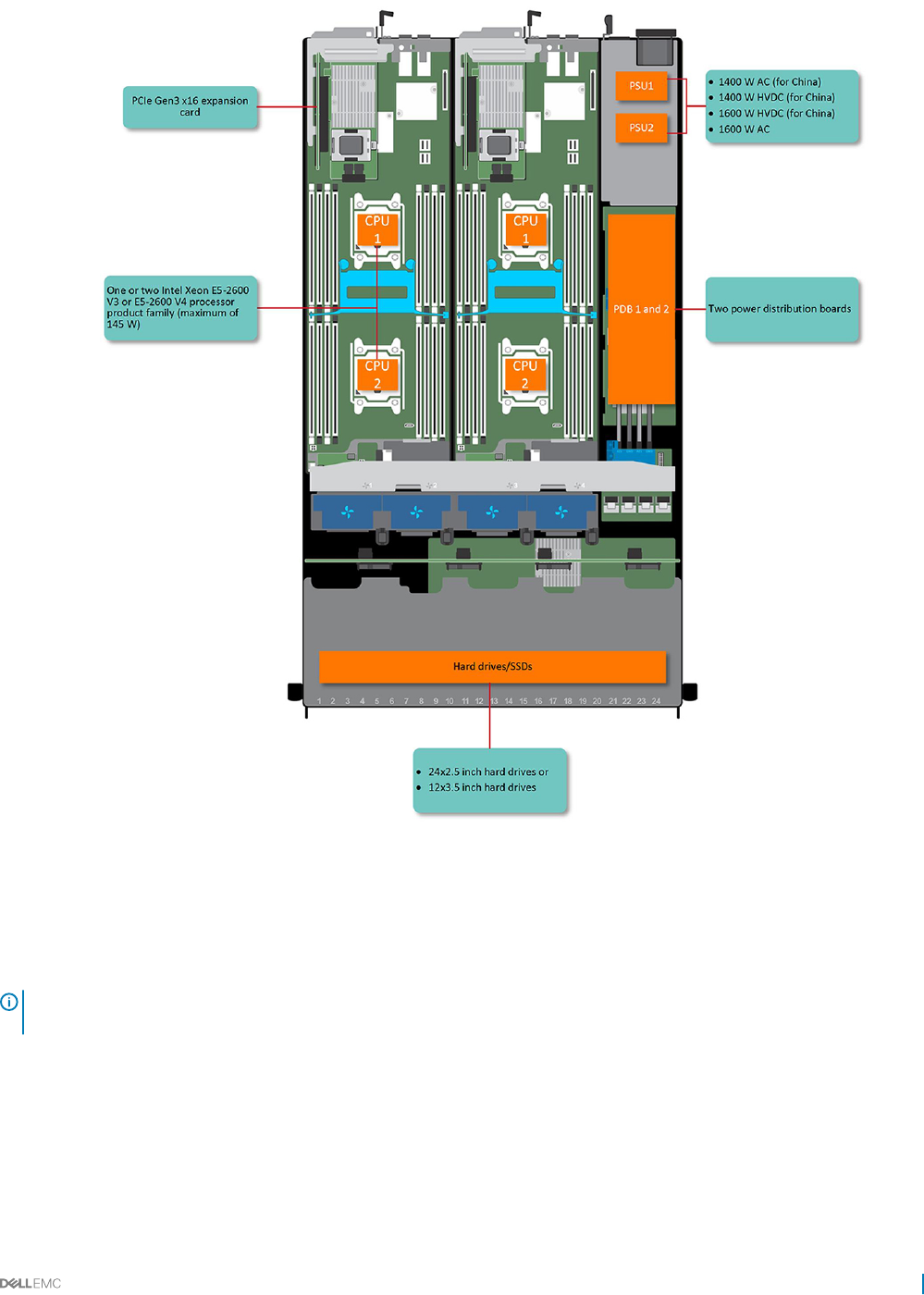
Figure 1. Supported congurations for C6320
Accessing system features during startup
The following keystrokes provide access to system features during startup.
NOTE: The hot keys of SAS or SATA card or PXE support are available in BIOS boot mode only. There is no hot key to boot in the
the UEFI mode.
Keystroke Description
F2 Enters the System Setup program.
F11 Enters the BIOS Boot Manager.
F12 Starts Preboot eXecution Environment (PXE)/iSCSI boot.
Dell PowerEdge C6320 product overview 9
Keystroke Description
Ctrl +C Enters the LSI 2008 SAS Mezzanine Card Conguration Utility. For more information, see the SAS adapter
documentation.
Ctrl+R Enters the PERC 9 Card Conguration Utility. For more information, see the documentation for your SAS RAID
card.
Ctrl+Y Enters the MegaPCLI SAS RAID Management Tool.
Ctrl+S Enters the utility to congure onboard LAN settings for PXE boot. For more information, see the documentation
for your integrated LAN.
Ctrl+I Enters onboard SATA Controller’s Conguration Utility.
Ctrl+D Enters the Intel iSCSI setup menu.
Front panel features and indicators
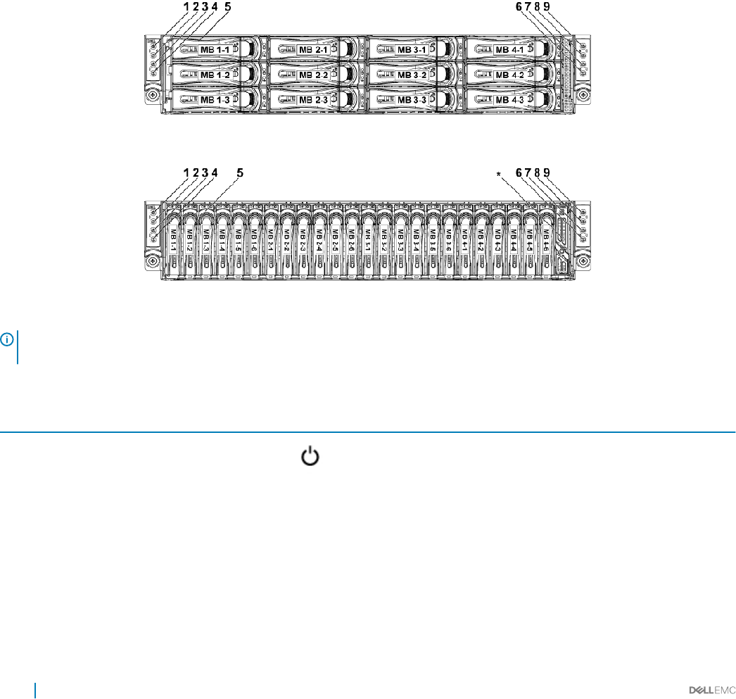
Figure 2. Front panel − 3.5-inch x12 hard drives with four system boards (C6320 RAID card and onboard SATA controller)
Figure 3. Front panel − 2.5-inch x24 hard drives with four system boards (C6320 RAID card and onboard SATA controller)
NOTE: For more information about the direction details of the 2.5-inch hard drive expander conguration support, see the HDD
Zoning conguration tool at Dell.com/support.
Table 1. Front panel features and indicators
Item Indicator, button or connector Icon Description
1Power-on indicator or system state
indicator or power button for system
board 1
The power-on indicator turns to green when the system
power is on.
The power-on indicator turns to amber when the system
critical event occurs.
The power button controls the DC power supply output to
the system.
3Power-on indicator or system state
indicator or power button for system
board 2
7Power-on indicator or system state
indicator or power button for system
board 4
10 Dell PowerEdge C6320 product overview
Item Indicator, button or connector Icon Description
9Power-on indicator or system state
indicator or power button for system
board 3
NOTE: When turning on the system, the video
monitor can take from several seconds to over two
minutes to display an image, depending on the
number and capacity of DIMMs installed in the
system.
NOTE: On ACPI-compliant operating systems
(OSs), turning o the system by using the power
button causes the system to perform a graceful
shutdown before power to the system is turned o.
NOTE: To force an ungraceful shutdown, press and
hold the power button for 5 seconds.
2 System identication indicator or button
for system board 1
The identication button can be used to locate a particular
system and system board within a chassis. When the button
is pushed, the blue status indicator of the system on the
front and rear blinks until the button is pushed again.
4 System identication indicator or button
for system board 2
6 System identication indicator or button
for system board 4
8 System identication indicator or button
for system board 3
5 Hard drives Up to 12 hot swappable 3.5-inch hard drives.
Up to 24 hot swappable 2.5-inch hard drives.
* Drive cover Applicable only for 2.5-inch hard drive systems. This is not a
usable drive slot.
Hard drive indicator patterns
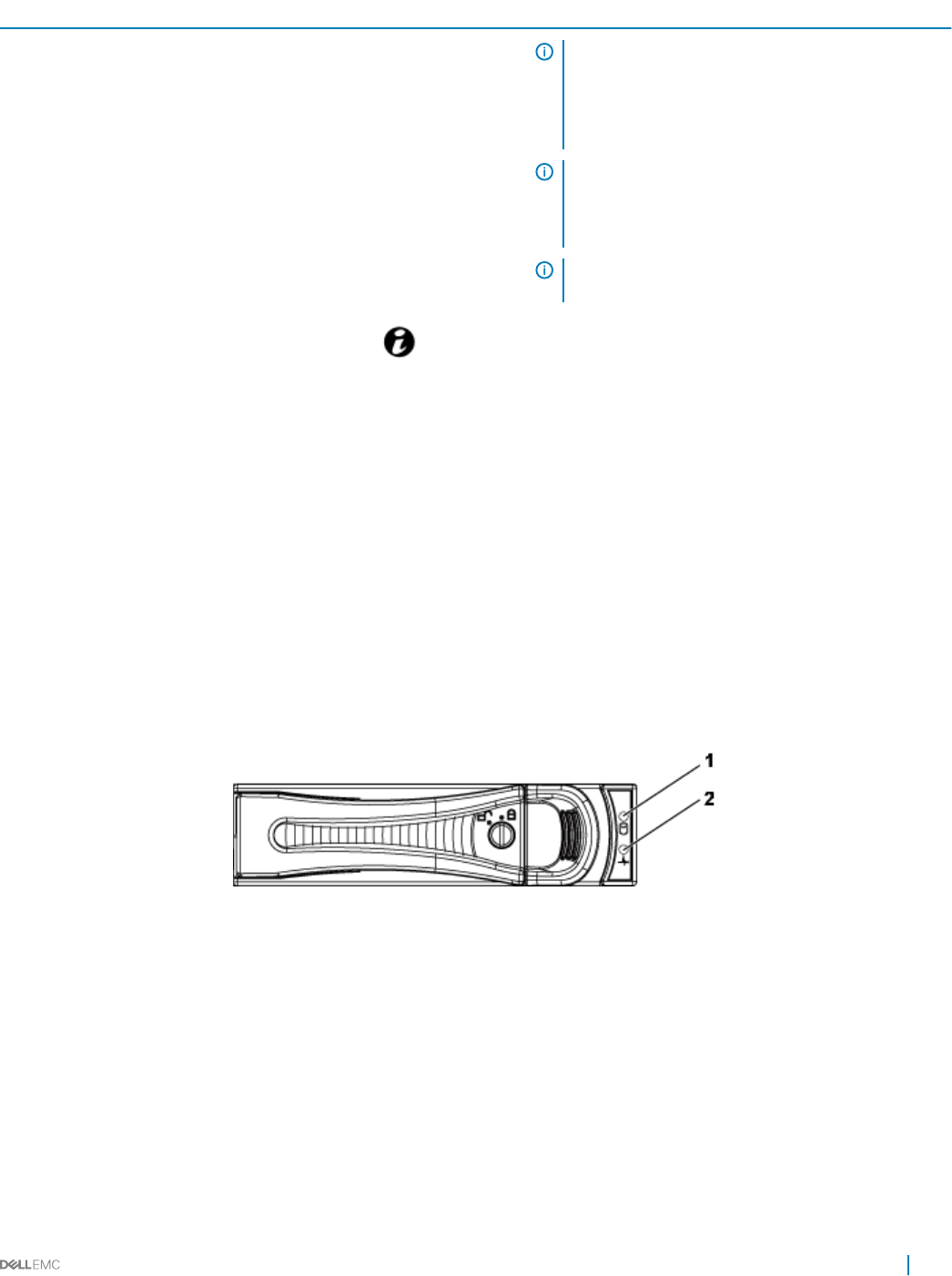
Figure 4. 3.5-inch hard drive indicators
1hard drive activity indicator (green) 2 hard drive status indicator (green and amber)
Dell PowerEdge C6320 product overview 11
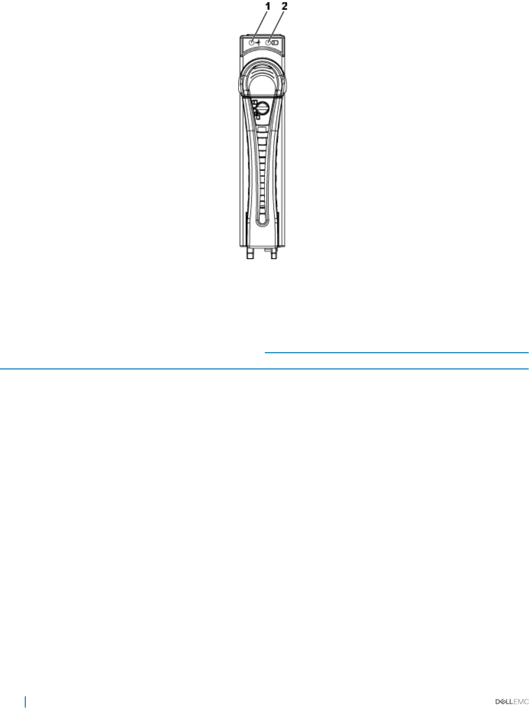
Figure 5. 2.5-inch hard drive indicators
1hard drive status indicator (green and amber) 2 hard drive activity indicator (green)
Table 2. Hard drive indicator patterns
Controller Hard drive type Function Activity LED Status LED
Green Green Amber
Onboard Controller SATA2 Drive on-line O/Blinking when
active
On O
Fail O On O
PERC 9/LSI 2008 SAS/SATA2 Slot Empty O O O
Drive on-line/Access Blinking when active On O
Drive identify/
prepare for removal
Blinking when active On 250 ms
O 250 ms
O
Drive Failed O O On 150 ms
O 150 ms
Drive Rebuild Blinking when active On 400 ms
O 100 ms
O
Predicted Failure
(SMART)
Blinking when active On 500 ms
O 500 ms
O 1000 ms
O 500 ms
On 500 ms
O 1000 ms
12 Dell PowerEdge C6320 product overview
Controller Hard drive type Function Activity LED Status LED
Green Green Amber
Rebuild Abort O On 3000 ms
O 9000 ms
O 6000 ms
On 3000 ms
O 000 ms
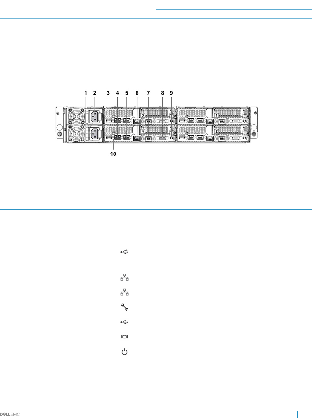
Back panel features and indicators
Figure 6. Back panel with four system boards
Table 3. Back panel features and indicators
Item Indicator, button, or connector Icon Description
1 PSU 2 Up to 1400 W AC, 1600 W AC, or 1400
HVDC PSUs.
2 PSU 1 Up to 1400 W AC, 1600 W AC, or 1400
HVDC PSUs.
3 USB port Enables you to connect USB devices to
the system. The ports are USB 3.0-
compliant.
4 Ethernet connector 10G NIC 1 connector.
5 Ethernet connector 10G NIC 2 connector.
6 Management port Dedicated management port.
7 USB to serial port Connects the system to a host.
8 VGA port Connects a VGA display to the system.
9 Power button/power and system LED The power-on indicator glows green
when the system power is on.
The power-on indicator turns amber
when the system critical event occurs.
Dell PowerEdge C6320 product overview 13
Item Indicator, button, or connector Icon Description
The power button controls the DC PSU
output to the system.
NOTE: When turning on the
system, the video monitor can
take from several seconds to
over two minutes to display an
image, on the basis of the disk
space available in the system.
NOTE: On ACPI-compliant
operating systems, turning o
the system by using the power
button causes the system to
perform a graceful shutdown
before the system is turned o.
NOTE: To force an ungraceful
shutdown, press and hold the
power button for ve seconds.
10 System identication indicator The management software of both the
systems and the identication buttons on
the front can cause the indicator to ash
blue to identify a particular system and
system board. Indicators turn amber
when the system requires attention
because of an issue.
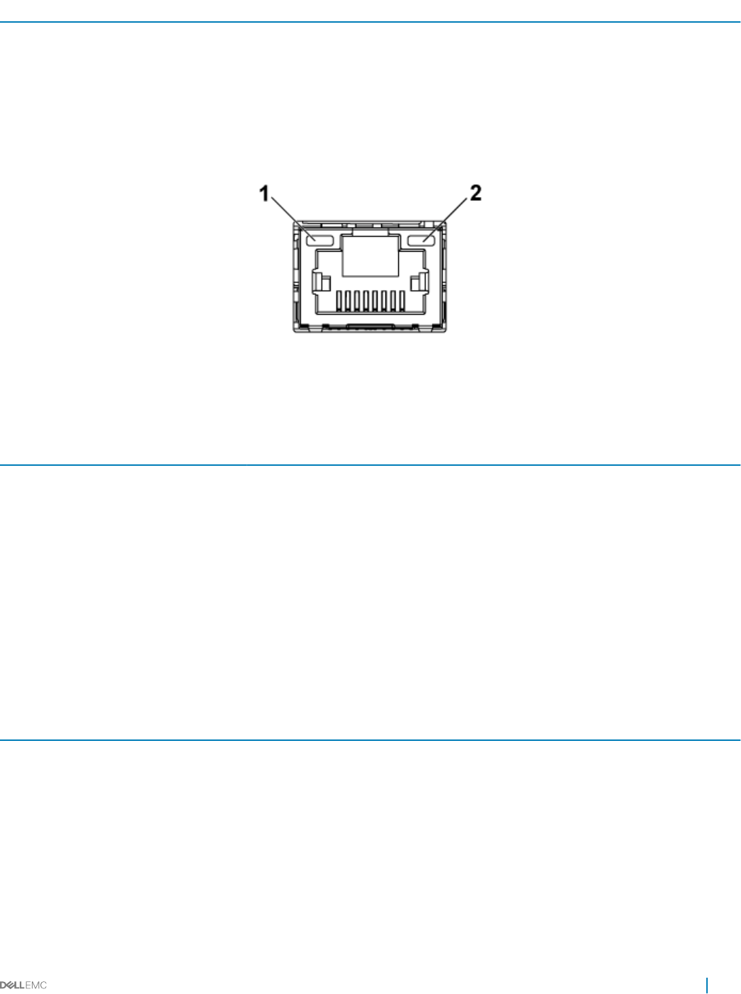
LAN indicator codes
Figure 7. LAN indicators
1activity indicator 2 link and network speed indicator
Table 4. LAN indicator codes
Component Indicator Condition
Link and network speed indicator Solid amber Linking at 1 Gbps speed
Solid green Linking at 10 Gbps speed
Activity indicator Blinking green Activity is present:
• Pre OS POST
• OS without driver
• OS with driver
14 Dell PowerEdge C6320 product overview
Component Indicator Condition
Blinking at speed relative to packet
density.
O No link/activity present
• D0 (uninitialized)
• D3 (cold)
• S4 (hibernation)
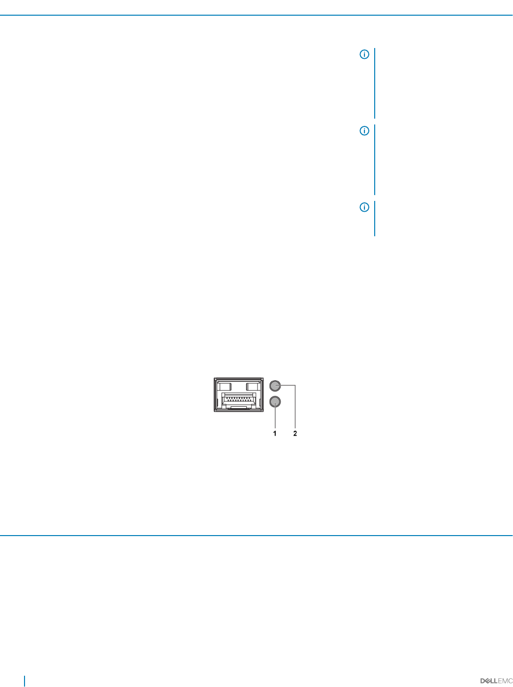
Figure 8. LAN indicators (management port)
1 speed indicator 2 link and activity indicator
Table 5. LAN indicators (management port)
Component Indicator Condition
Speed indicator Solid green Linking at 1 Gbps speed
Solid amber Linking at 10/100 Mbps speed
Link and activity indicator O No access or Idle
Blinking green LAN access or Link up
Power and system board indicator codes
The LEDs on the system front panel and back panel display status codes during system startup. For location of the LEDs on the front
panel, see the Front panel features and indicators section. For location of the LEDs on the back panel, see the Back panel features and
indicators section.
Table 6. Status indicator codes
Component Indicator Condition
Power-on indicator (A bicolor
LED on power button)
Green Solid Power On (S0)
Amber O
Green O BMC critical condition event in Power O mode (S4/S5)
Amber Blinking
Green O BMC critical condition event in Power On mode (S0)
Amber Blinking
System identication indicator Steady blue IPMI using Chassis Identify Command On or ID Button Press ID
On
Dell PowerEdge C6320 product overview 15
Component Indicator Condition
Blinking blue Only IPMI using Chassis Identify Command Blink On
O IPMI using Chassis Identify Command O or ID Button Press ID
O
Related links
Front panel features and indicators
Back panel features and indicators
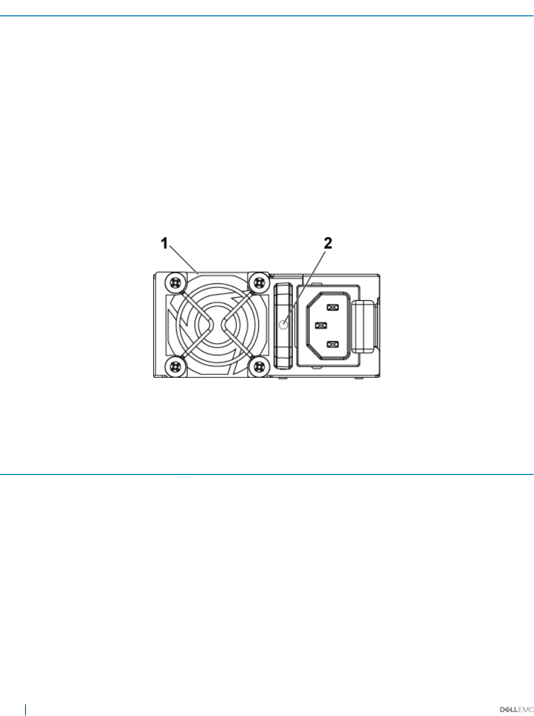
Power Supply Unit indicator codes
Each AC power supply unit (PSU) has an illuminated translucent handle that indicates whether power is present or whether a power fault
has occurred.
1400 W AC/1400 W HVDC PSUs
Figure 9. PSU status indicators
1PSU 2 AC power indicator
Table 7. 1400 W AC/1400 W HVDC PSUs indicators
Component Indicator Condition
AC or DC power indicator Solid amber Fault (fault of any kind)
Solid green DC_OK (power good)
Blinking green AC_OK
16 Dell PowerEdge C6320 product overview
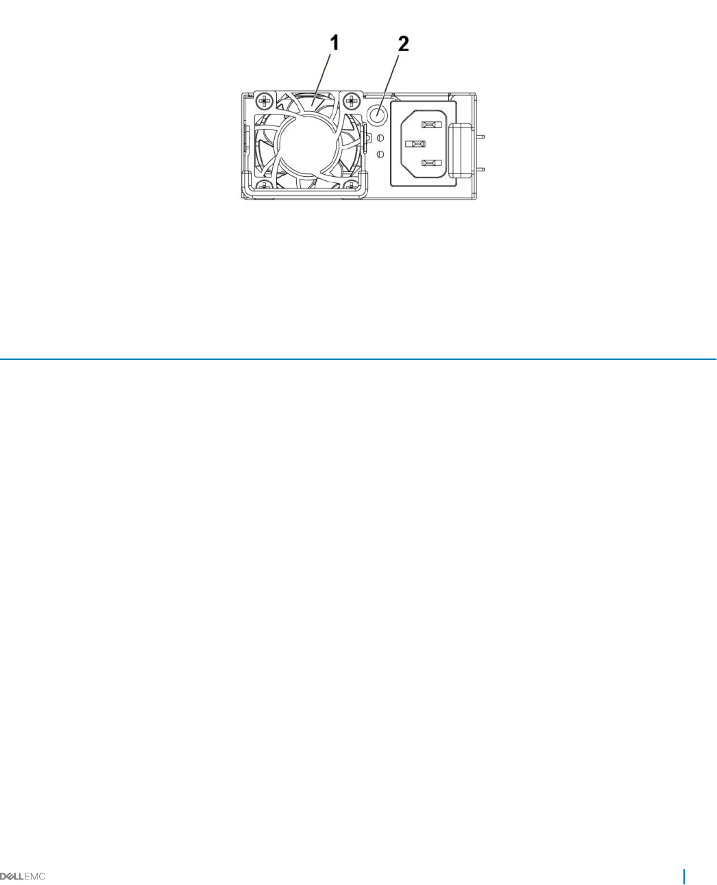
1600 W AC/1600 W HVDC PSU
Figure 10. PSU status indicator
1 PSU 2 AC power indicator
Table 8. 1600 W AC/1600 W HVDC PSU indicators
Component Indicator Condition
AC power indicator Solid amber Standby mode with Fan Lock for 15
seconds.
Standby mode with OTP range
Active mode with +12 V DC Fault
Active mode with Fan Lock for 15 seconds.
Solid green DC_OK (power good)
Blinking green Standby mode normal
O Unit without AC power
Dell PowerEdge C6320 product overview 17
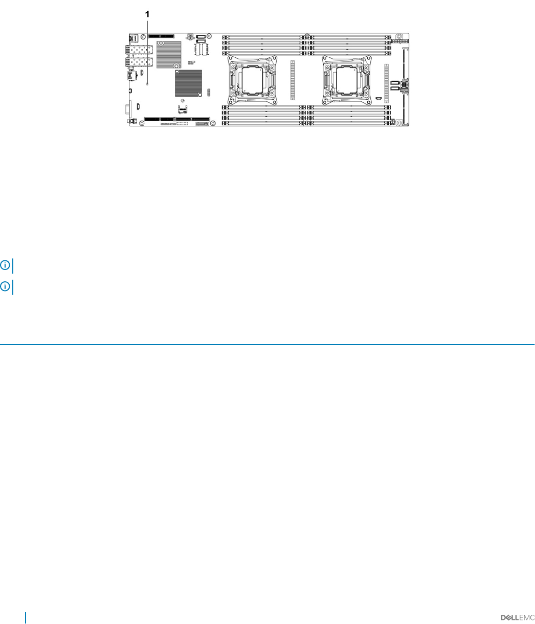
Baseboard Management Controller (BMC) heart beat
LED
The system board provides BMC heart beat LED (CR17) for BMC debugs. The BMC heart beat LED is green. When the system AC power
is connected, the LED glows. When BMC rmware is ready, the BMC heart beat LED blinks.
Figure 11. BMC heart beat LED on the C6320 system board
1 BMC heart beat LED
System conguration limitations by Intel Xeon
processor E5-2600 v3 and E5-2600 v4 product family
NOTE: Certain system hardware congurations may require reductions in the upper temperature limits.
NOTE: System performance may be impacted when operating above 30°C or with a fan fault.
Table 9. Conguration restrictions with Intel Xeon processor E5-2600 v3 and E5-2600 v4 product family
Processor 3.5-inch hard drive chassis 2.5-inch hard drive chassis
55 W
E5-2630L v3
E5-2630L v4
No conguration restrictions No conguration restrictions
60 W
E5-2650L v3
65 W
E5-2650L v4
85 W
E5-2603 v3
E5-2630 v3
E5-2620 v3
18 Dell PowerEdge C6320 product overview

Processor 3.5-inch hard drive chassis 2.5-inch hard drive chassis
E5-2630 v4
E5-2623 v4
E5-2620 v4
E5-2609 v4
E5-2603 v4
90 W
E5-2640 v3
E5-2640 v4
105 W
E5-2660 v3
E5-2650 v3
E5-2623 v3
E5-2660 v4
E5-2650 v4
120 W
E5-2683 v3
E5-2685 v3
E5-2695 v3
E5-2680 v3
E5-2670 v3
E5-2695 v4
E5-2683 v4
E5-2680 v4
PERC H730 is not supported PERC H730 is not supported
135 W (16 cores and 12 cores)
E5-2698 v3
E5-2690 v3
PERC H730/H330 are not supported
PERC H730/H330 are not supported
135 W (14 cores and 20 cores)
E5-2698 v4
E5-2690 v4
PERC H730/330 are not supported
135 W (8 cores) and 145 W
E5-2667 v3
• PERC H730/H330 are not supported
• Restricted to total 8 hard drives
Dell PowerEdge C6320 product overview 19

Processor 3.5-inch hard drive chassis 2.5-inch hard drive chassis
145 W (14 cores)
E5-2697 v3
145 W (18 cores)
E5-2699 v3
135W (8/6/4 cores) and 145W
(22/18/16 cores)
E5-2667 v4
E5-2643 v4
E5-2637 v4
E5-2699 v4
E5-2697 v4
E5-2697A v4
• PERC H730/H330 are not supported
• Restricted to total 8 hard drives
PERC H730/330 are not supported
Table 10. Fresh air cooling conguration restrictions
Processor 3.5-inch hard drive chassis 2.5-inch hard drive chassis
55W
E5-2630L v4
PERC H730 is not supported PERC H730 is not supported
65W
E5-2650L v4
85 W
E5-2630 v3
E5-2620 v3
E5-2603 v3
E5-2630 v4
E5-2623 v4
E5-2620 v4
E5-2609 v4
E5-2603 v4
90 W
E5-2640 v3
E5-2640 v4
20 Dell PowerEdge C6320 product overview

Processor 3.5-inch hard drive chassis 2.5-inch hard drive chassis
105 W
E5-2660 v3
E5-2650 v3
E5-2623 v3
E5-2660 v4
E5-2650 v4
120 W
E5-2695 v3
E5-2680 v3
E5-2670 v3
E5-2695 v4
E5-2683 v4
E5-2680 v4
Support maximum 8x hard drives
PERC H730/H330 are not supported
Support maximum 12x hard drives
PERC H730/H330 are not
supported
135 W (16 cores and 12 cores)
E5-2698 v3
E5-2690 v3
Not supported Not supported
135 W (20 cores and 14 cores)
E5-2698 v4
E5-2690 v4
135 W (8 cores) and 145 W
E5-2699 v3
145 W (14 cores)
E5-2697 v3
135W (8/6/4 cores) and 145W (22/18/16 cores)
E5-2667 v4
E5-2643 v4
E5-2637 v4
E5-2699 v4
E5-2697 v4
E5-2697A v4
Dell PowerEdge C6320 product overview 21
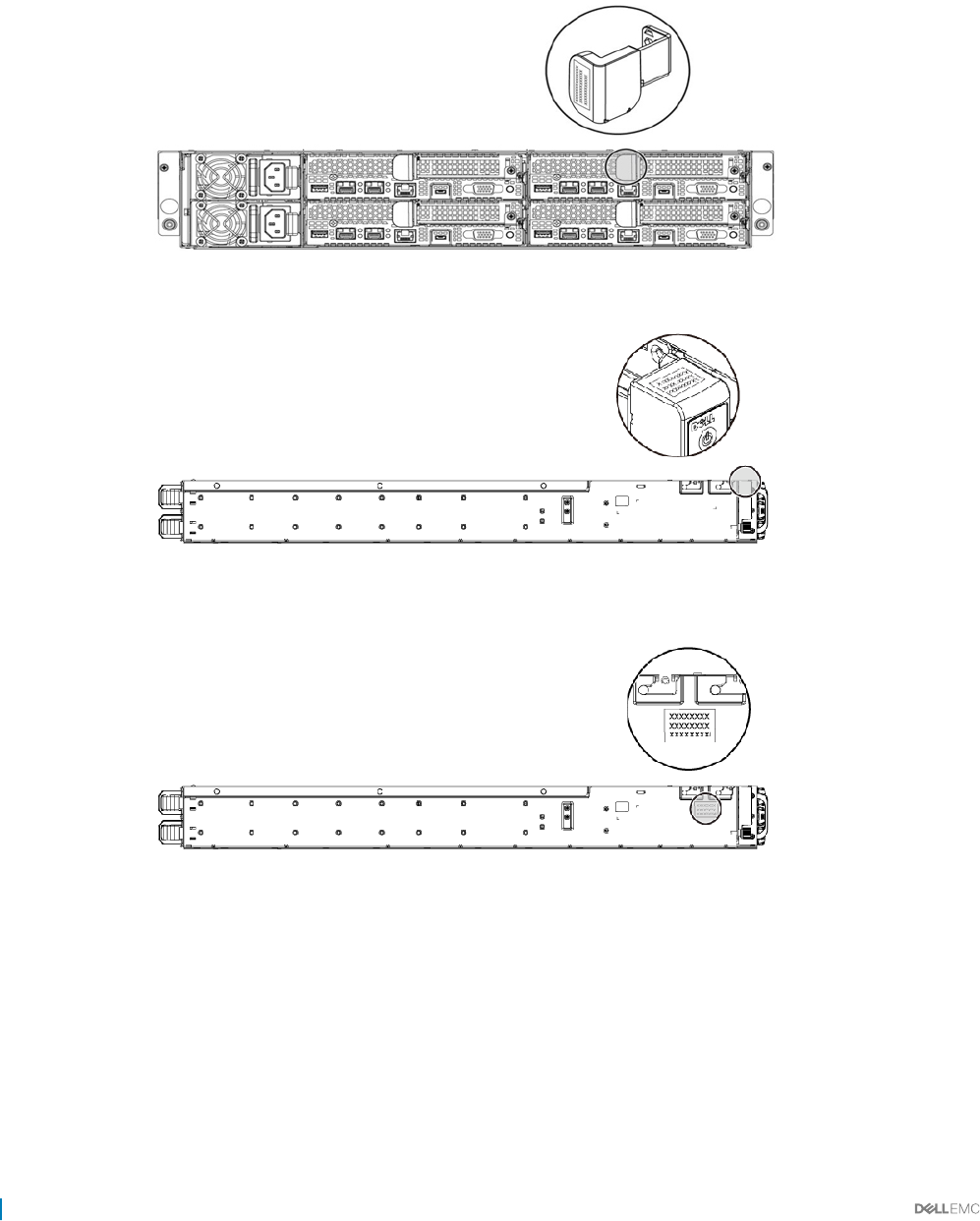
Locating your system Service Tag
Your system is identied by a unique Express Service Code and Service Tag number. The Express Service Code is found on the front of the
system and Service Tag is found on the front of the system. Alternatively, the information may be on a sticker on the chassis of the system.
This information is used by Dell to route support calls to the appropriate personnel. The Service Tag locations on the chassis are as follows:
Figure 12. Service Tag location
Figure 13. Service Tag location on the left front panel
Figure 14. Service Tag location on the chassis
Hard drives under warranties are linked to each node with an appropriate service tag. The linked hard drives with the node is shown in the
below gure.
22 Dell PowerEdge C6320 product overview
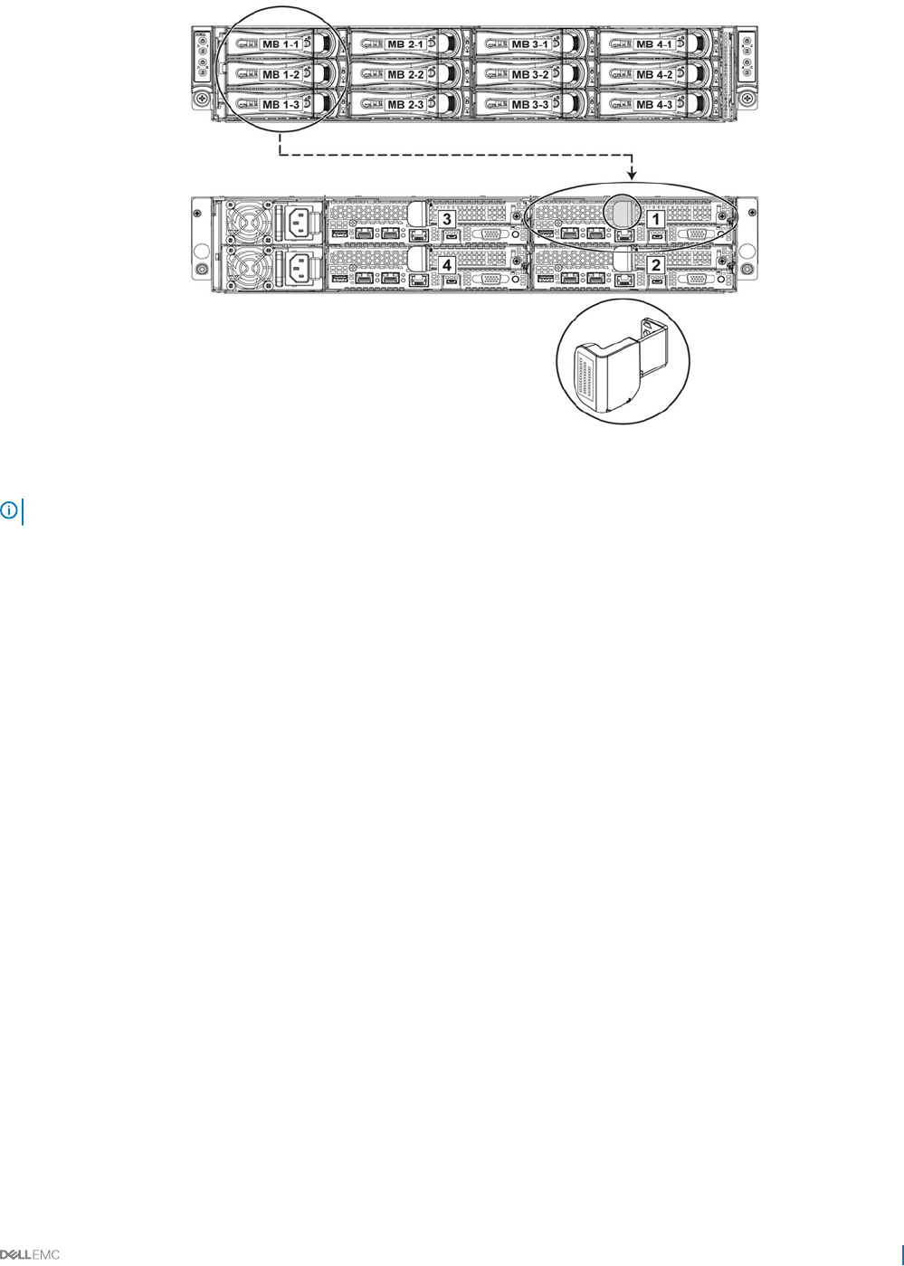
Figure 15. Service Tag linkage
NOTE: Hard drives that are under warranty are linked to the appropriate Service Tag of the node.
Dell PowerEdge C6320 product overview 23

Documentation resources
This section provides information about the documentation resources for your system.
Table 11. Documentation resources for system
Task Document Location
Setting up your system For information about installing the system into a
rack, see theRack documentation included with
your rack solution or the Getting Started With Your
System document that is shipped with your
system.
Dell.com/poweredgemanuals
For information about turning on the system and
the technical specications of your system, see the
Getting Started With Your System document that
is shipped with your system.
Dell.com/poweredgemanuals
Conguring your system For information about iDRAC features, conguring
and logging in to iDRAC, and managing your system
remotely, see the Integrated Dell Remote Access
Controller User's Guide.
Dell.com/idracmanuals
For information about installing the operating
system, see the operating system documentation.
Dell.com/operatingsystemmanuals
For information about understanding Remote
Access Controller Admin (RACADM)
subcommands and supported RACADM interfaces,
see the RACADM Command Line Reference Guide
for iDRAC.
Dell.com/idracmanuals
For information about updating drivers and
rmware, see theMethods to download rmware
and drivers section in this document.
Dell.com/support/drivers
Managing your system For information about the features of the Dell
OpenManage Systems Management, see the Dell
OpenManage Systems Management Overview
Guide.
Dell.com/openmanagemanuals
For information about setting up, using, and
troubleshooting OpenManage, see the Dell
OpenManage Server Administrator User’s Guide.
Dell.com/openmanagemanuals
For information about installing, using, and
troubleshooting Dell OpenManage Essentials, see
the Dell OpenManage Essentials User’s Guide.
Dell.com/openmanagemanuals
For information about installing and using Dell
System E-Support Tool (DSET), see the Dell
System E-Support Tool (DSET) User's Guide.
Dell.com/DSET
2
24 Documentation resources

Task Document Location
For information about installing and using Active
System Manager (ASM), see the Active System
Manager User’s Guide.
Dell.com/asmdocs
For understanding the features of Dell Lifecycle
Controller (LCC), see the Dell Lifecycle Controller
User’s Guide.
Dell.com/idracmanuals
For information about partner programs enterprise
systems management, see the OpenManage
Connections Enterprise Systems Management
documents.
Dell.com/
omconnectionsenterprisesystemsmanagement
For information about connections and client
systems management, see the OpenManage
Connections Client Systems Management
documentation.
Dell.com/dellclientcommandsuitemanuals
For information about viewing inventory,
performing conguration and monitoring tasks,
remotely turning on or o servers, and enabling
alerts for events on servers and components using
the Dell Chassis Management Controller (CMC),
see the CMC User’s Guide.
Dell.com/esmmanuals
Working with Dell PowerEdge
RAID controllers
For information about understanding the features
of the Dell PowerEdge RAID controllers (PERC)
and deploying the PERC cards, see the Storage
controller documentation.
Dell.com/storagecontrollermanuals
Understanding event and error
messages
For information about checking the event and error
messages generated by the system rmware and
agents that monitor system components, see the
Dell Event and Error Messages Reference Guide.
Dell.com/openmanagemanuals > OpenManage
software
Documentation resources 25
Technical specications
The technical and environmental specications of your system are outlined in this section.
Chassis dimensions
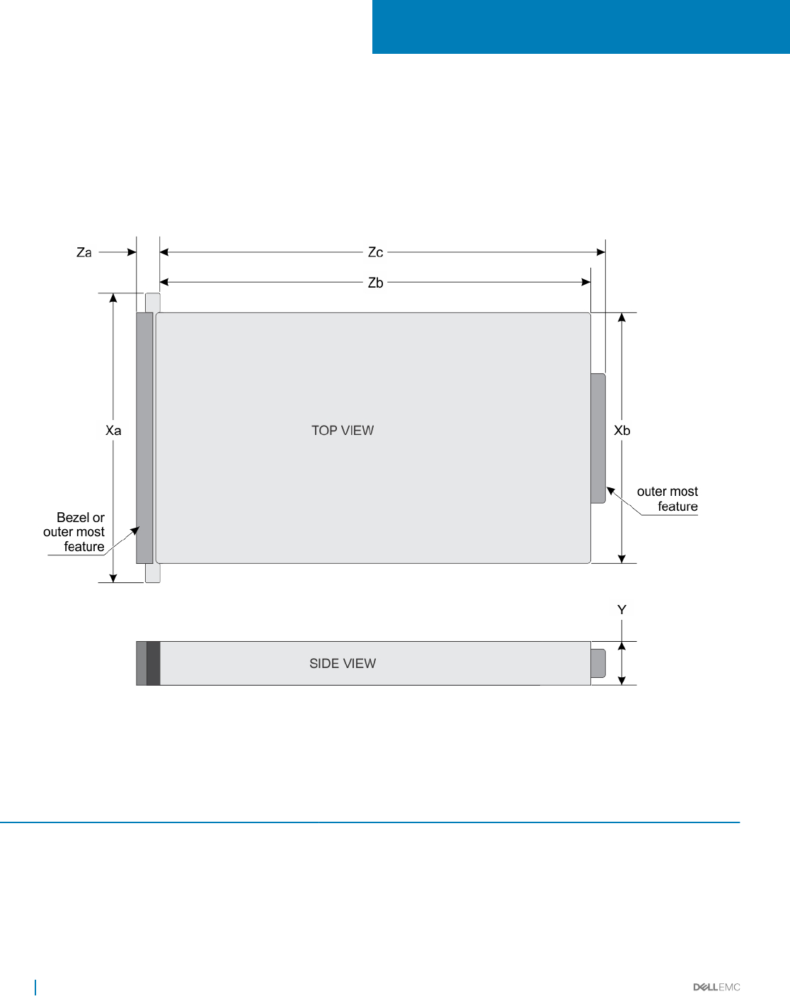
Figure 16. Chassis dimensions of PowerEdge C6320 system
Table 12. Dimensions of the Dell PowerEdge C6320 system
Xa Xb Y Za (with bezel) Za (without
bezel)
Zb Zc
482.4 mm 448.0 mm 86.8 mm 28.2 mm 28.2 mm 764.2 mm 790.3 mm
3
26 Technical specications

Processor specications
Dell PowerEdge C6320 supports up to two Intel Xeon E5-2600 v3 or Intel Xeon E5-2600 v4 product family processors in four independent
servers.
PSU specications
Dell PowerEdge C6320 system supports up to two AC or HVDC power supply units (PSUs). Dell PowerEdge C6320 does not support a
mixed installation of 1400 W and 1600 W power supply units. The 1400 W and 1600 W power supply units are hot swappable, and supports
hot swap in any condition if the system has the power throttling feature enabled.
Table 13. PSU specications
PSU Heat dissipation
(maximum)
Frequency Voltage Maximum input
current
Maximum inrush
current (peak)
1400 W AC 5220.763 BTU/hr 50/60 Hz 200-240 V AC 9 A Initial inrush current
cannot exceed 55 A
(peak).
Secondary inrush
current cannot
exceed 25 A (peak).
1600 W AC 5966.586 BTU/hr 50/60 Hz 100-120 V AC
200-240 V AC
12 A
10 A
Initial inrush current
and secondary inrush
current cannot
exceed 35 A (peak).
1400 W HVDC (for
China only)
5220.763 BTU/hr – 240 V DC 9 A Initial inrush current
cannot exceed 55 A
(peak).
Secondary inrush
current cannot
exceed 25 A (peak).
System battery specications
Dell PowerEdge C6320 system supports CR 2032 3.0-V lithium coin cell battery.
Memory specications
Dell PowerEdge C6320 system supports DDR4 registered DIMMs (RDIMMs).
Table 14. Memory specications
Memory module sockets Architecture Memory capacity Minimum RAM Maximum RAM
Sixteen 288-pin 1600 MT/s, 1866 MT/s,
2133 MT/s, or 2400 MT/s
DDR4 Registered DIMMs
with support for
advanced ECC or
memory optimized
operation
8 GB, 16 GB, and 32 GB
dual-rank
16 GB Up to 512 GB
Technical specications 27
Environmental specications
NOTE: For additional information about environmental measurements for specic system congurations, see Dell.com/
environmental_datasheets
Table 15. Temperature specications
Temperature Specications
Storage –40° to 65°C (–40° to 149°F) with a maximum temperature
gradation of 20°C per hour.
Continuous operation (for altitude less than 950 m or 3117 ft) 10°C to 35°C (50°F to 95°F) with no direct sunlight on the
equipment.
Fresh air For information on fresh air, see Expanded Operating Temperature
section.
Maximum temperature gradient (operating and storage) 20°C/h (36°F/h)
Table 16. Expanded operating temperature specications
Expanded operating temperature Specications
NOTE: When operating in the expanded temperature range, system performance may be impacted.
NOTE: When operating in the expanded temperature range, ambient temperature warnings may be reported on the LCD and
in the System Event Log.
Continuous operation 5°C to 40°C at 5% to 85% RH with 29°C dew point.
NOTE: Outside the standard operating temperature (10°C
to 35°C), the system can operate down to 5°C or up to
40°C.
For temperatures between 35°C and 40°C, de-rate maximum
allowable dry bulb temperature by 1°C per 175 m above 950 m (1°F
per 319 ft).
≤ 1% of annual operating hours –5°C to 45°C at 5% to 90% RH with 26°C dew point.
NOTE: Outside the standard operating temperature (10°C
to 35°C), the system can operate down to –5°C or up to
45°C for a maximum of 1% of its annual operating hours.
For temperatures between 40°C and 45°C, de-rate maximum
allowable dry bulb temperature by 1°C per 125 m above 950 m (1°F
per 228 ft).
Expanded operating temperature restrictions • Do not perform a cold startup below 5 °C.
• Maximum 120 W processor is supported.
• Maximum of eight 3.5 inch or twelve 2.5 inch hard drives are
supported with 120 W processor.
The following do not support the expanded operating temperature
range:
• Dell PowerEdge RAID Controller (PERC) H730/H730P cards
with CPU TDP ≥ 85 W.
28 Technical specications

Expanded operating temperature Specications
• Dell PowerEdge RAID Controller (PERC) H330 card with CPU
TDP ≥ 120 W.
• Non Dell-qualied peripheral cards and/or peripheral cards
greater than 25 W are not supported.
Table 17. Relative humidity specications
Relative humidity Specications
Operating 20% to 80% (noncondensing) with a maximum humidity gradation
of 10% per hour
Storage 5% to 95% (non-condensing)
Table 18. Maximum vibration specications
Maximum vibration Specications
Operating 0.26 Grms at 5–350 Hz
Storage 1.88 Grms at 10–500 Hz for 15 minutes
Table 19. Maximum shock specications
Maximum shock Specications
Operating One shock pulse in the positive z axis (one pulse on each side of the
system) of 31 G for 2.6 ms in the operational orientation.
Storage Six consecutively executed shock pulses in the positive and
negative x, y, and z axes (one pulse on each side of the system) of
71 G for up to 2 ms
Six consecutively executed shock pulses in the positive and
negative x, y, and z axes (one pulse on each side of the system) of
27 G faired square wave pulse with velocity change at 235 inches
per second (597 centimeters per second)
Table 20. Maximum altitude specications
Maximum altitude Specications
Operating -15.2 m to 3,048 m (-50 to 10,000 ft.)
Storage -15.2 m to 10,668 m (-50 to 35,000 ft.)
Table 21. Airborne contaminant level specication
Airborne contaminant level (Class) G1 as dened by ISA-S71.04-1985
Technical specications 29

Initial system setup and conguration
Setting up your system
Complete the following steps to set up your system:
1 Unpack the system.
2 Install the system into the rack. For more information about installing the system into the rack, see your Dell PowerEdge C6320
Getting Started Guide at Dell.com/poweredgemanuals.
3 Connect the peripherals to the system.
4 Connect the system to its electrical outlet.
5 Turn the system on by pressing the power button or by using iDRAC.
6 Turn on the attached peripherals.
iDRAC conguration
The Integrated Dell Remote Access Controller (iDRAC) is designed to make system administrators more productive and improve the overall
availability of Dell systems. iDRAC alerts administrators to system issues, helps them perform remote system management, and reduces the
need for physical access to the system.
Options to set up iDRAC IP address
You must congure the initial network settings based on your network infrastructure to enable the communication to and from iDRAC. You
can set up the IP address by using one of the following interfaces:
Interfaces Document/Section
iDRAC Settings
utility
See Dell Integrated Dell Remote Access Controller User's Guide at Dell.com/idracmanuals
Dell Deployment
Toolkit
See Dell Deployment Toolkit User’s Guide at Dell.com/openmanagemanuals
Dell Lifecycle
Controller
See Dell Lifecycle Controller User’s Guide at Dell.com/idracmanuals
Chassis or Server
LCD panel
See the LCD panel section
You must use the default iDRAC IP address 192.168.0.120 to congure the initial network settings, including setting up DHCP or a static IP
for iDRAC.
NOTE: To access iDRAC, ensure that you install the iDRAC port card or connect the network cable to the Ethernet connector 1
on the system board.
NOTE: Ensure that you change the default user name and password after setting up the iDRAC IP address.
4
30 Initial system setup and conguration

Log in to iDRAC
You can log in to iDRAC as:
• iDRAC user
• Microsoft Active Directory user
• Lightweight Directory Access Protocol (LDAP) user
The default user name and password are root and calvin. You can also log in by using Single Sign-On or Smart Card.
NOTE: You must have iDRAC credentials to log in to iDRAC.
For more information about logging in to iDRAC and iDRAC licenses, see the Integrated Dell Remote Access Controller User's Guide at
Dell.com/idracmanuals.
Options to install the operating system
If the system is shipped without an operating system, install the supported operating system by using one of the following resources:
Table 22. Resources to install the operating system
Resources Location
Dell Systems Management Tools and Documentation media Dell.com/operatingsystemmanuals
Dell Lifecycle Controller Dell.com/idracmanuals
Dell OpenManage Deployment Toolkit Dell.com/openmanagemanuals
Dell certied VMware ESXi Dell.com/virtualizationsolutions
Supported operating systems on Dell PowerEdge systems Dell.com/ossupport
Installation and How-to videos for supported operating systems on
Dell PowerEdge systems
Supported Operating Systems for Dell PowerEdge Systems
Methods to download rmware and drivers
You can download the rmware and drivers by using the following methods:
Table 23. Firmware and drivers
Methods Location
From the Dell Support site Dell.com/support/home
Using Dell Remote Access Controller Lifecycle Controller (iDRAC
with LC)
Dell.com/idracmanuals
Using Dell Repository Manager (DRM) Dell.com/openmanagemanuals
Using Dell OpenManage Essentials (OME) Dell.com/openmanagemanuals
Using Dell Server Update Utility (SUU) Dell.com/openmanagemanuals
Using Dell OpenManage Deployment Toolkit (DTK) Dell.com/openmanagemanuals
Initial system setup and conguration 31

Downloading the drivers and rmware
Dell recommends that you download and install the latest BIOS, drivers, and systems management rmware on your system.
Prerequisites
Ensure that you clear the web browser cache before downloading the drivers and rmware.
Steps
1 Go to Dell.com/support/drivers.
2 Under the Drivers & Downloads section, type the Service Tag of your system in the Service Tag or Express Service Code box.
NOTE: If you do not have the Service Tag, select Detect My Product to allow the system to automatically detect your
Service Tag, or under General support, navigate to your product.
3 Click Drivers & Downloads.
The drivers that are applicable to your selection are displayed.
4 Download the drivers you need to a USB drive, CD, or DVD.
32 Initial system setup and conguration

Pre-operating system management applications
You can manage basic settings and features of a system without booting to the operating system by using the system rmware.
Options to manage the pre-operating system
applications
Your system has the following options to manage the pre-operating system applications:
• System Setup
• Boot Manager
• Dell Lifecycle Controller
• Preboot Execution Environment (PXE)
Related links
System Setup
Boot Manager
Dell Lifecycle Controller
PXE boot
System Setup
By using the System Setup screen, you can congure the BIOS settings, iDRAC settings, and device settings of your system.
NOTE: Help text for the selected eld is displayed in the graphical browser by default. To view the help text in the text browser,
press F1.
You can access system setup by using two methods:
• Standard graphical browser — The browser is enabled by default.
• Text browser — The browser is enabled by using Console Redirection.
Related links
System Setup details
Viewing System Setup
Viewing System Setup
To view the System Setup screen, perform the following steps:
1 Turn on, or restart your system.
2 Press F2 immediately after you see the following message:
F2 = System Setup
NOTE: If your operating system begins to load before you press F2, wait for the system to nish booting, and then
restart your system and try again.
5
Pre-operating system management applications 33

Related links
System Setup
System Setup details
System Setup details
The System Setup Main Menu screen details are explained as follows:
Option Description
System BIOS Enables you to congure BIOS settings.
iDRAC Settings Enables you to congure iDRAC settings.
The iDRAC settings utility is an interface to set up and congure the iDRAC parameters by using UEFI (Unied
Extensible Firmware Interface). You can enable or disable various iDRAC parameters by using the iDRAC settings
utility. For more information about this utility, see Integrated Dell Remote Access Controller User’s Guide at
Dell.com/idracmanuals.
Device Settings Enables you to congure device settings.
Related links
System Setup
System BIOS
iDRAC Settings utility
Device Settings
Viewing System Setup
System BIOS
You can use the System BIOS screen to edit specic functions such as boot order, system password, setup password, set the RAID mode,
and enable or disable USB ports.
Related links
System BIOS Settings details
Boot Settings
Network Settings
System Information
Memory Settings
Processor Settings
SATA Settings
Integrated Devices
Serial Communication
System Prole Settings
Miscellaneous Settings
iDRAC Settings utility
Device Settings
Viewing System BIOS
34 Pre-operating system management applications

Viewing System BIOS
To view the System BIOS screen, perform the following steps:
1 Turn on, or restart your system.
2 Press F2 immediately after you see the following message:
F2 = System Setup
NOTE: If your operating system begins to load before you press F2, wait for the system to nish booting, and then
restart your system and try again.
3 On the System Setup Main Menu screen, click System BIOS.
Related links
System BIOS
System BIOS Settings details
System BIOS Settings details
The System BIOS Settings screen details are explained as follows:
Option Description
System Information Species information about the system such as the system model name, BIOS version, and Service Tag.
Memory Settings Species information and options related to the installed memory.
Processor Settings Species information and options related to the processor such as speed and cache size.
SATA Settings Species options to enable or disable the integrated SATA controller and ports.
Boot Settings Species options to specify the boot mode (BIOS or UEFI). Enables you to modify UEFI and BIOS boot settings.
Network Settings Species options to change the network settings.
Integrated Devices Species options to manage integrated device controllers and ports and specify related features and options.
Serial
Communication
Species options to manage the serial ports and specify related features and options.
System Prole
Settings
Species options to change the processor power management settings, memory frequency, and so on.
System Security Species options to congure the system security settings, such as system password, setup password, Trusted
Platform Module (TPM) security. It also manages the power and NMI buttons on the system.
Miscellaneous
Settings
Species options to change the system date, time, and so on.
Related links
System BIOS
Viewing System BIOS
Pre-operating system management applications 35

System Information
You can use the System Information screen to view system properties such as Service Tag, system model name, and the BIOS version.
Related links
System Information details
System BIOS
Viewing System Information
Viewing System Information
To view the System Information screen, perform the following steps:
1 Turn on, or restart your system.
2 Press F2 immediately after you see the following message:
F2 = System Setup
NOTE: If your operating system begins to load before you press F2, wait for the system to nish booting, and then
restart your system and try again.
3 On the System Setup Main Menu screen, click System BIOS.
4 On the System BIOS screen, click System Information.
Related links
System Information
System Information details
System Information details
The System Information screen details are explained as follows:
Option Description
System Model
Name
Species the system model name.
System BIOS
Version
Species the BIOS version installed on the system.
System
Management
Engine Version
Species the current version of the Management Engine rmware.
System Service Tag Species the system Service Tag.
System
Manufacturer
Species the name of the system manufacturer.
System
Manufacturer
Contact
Information
Species the contact information of the system manufacturer.
System CPLD
Version
Species the current version of the system complex programmable logic device (CPLD) rmware.
UEFI Compliance
Version
Species the UEFI compliance level of the system rmware.
36 Pre-operating system management applications

Related links
System Information
System Information details
Viewing System Information
Memory Settings
You can use the Memory Settings screen to view all the memory settings and enable or disable specic memory functions, such as system
memory testing and node interleaving.
Related links
Memory Settings details
System BIOS
Viewing Memory Settings
Viewing Memory Settings
To view the Memory Settings screen, perform the following steps:
1 Turn on, or restart your system.
2 Press F2 immediately after you see the following message:
F2 = System Setup
NOTE: If your operating system begins to load before you press F2, wait for the system to nish booting, and then
restart your system and try again.
3 On the System Setup Main Menu screen, click System BIOS.
4 On the System BIOS screen, click Memory Settings.
Related links
Memory Settings
Memory Settings details
Memory Settings details
The Memory Settings screen details are explained as follows:
Option Description
System Memory
Size
Species the memory size in the system.
System Memory
Type
Species the type of memory installed in the system.
System Memory
Speed
Species the system memory speed.
System Memory
Voltage
Species the system memory voltage.
Video Memory Species the amount of video memory.
System Memory
Testing
Species whether the system memory tests are run during system boot. Options are Enabled and Disabled. This
option is set to Disabled by default.
Memory Operating
Mode
Species the memory operating mode. The available option is Optimizer Mode.
Node Interleaving Species if Non-Uniform Memory architecture (NUMA) is supported. If this eld is set to Enabled, memory
interleaving is supported if a symmetric memory conguration is installed. If the eld is set to Disabled, the system
supports NUMA (asymmetric) memory congurations. This option is set to Disabled by default.
Pre-operating system management applications 37

Option Description
Snoop Mode Species the Snoop Mode options. The Snoop Mode options available are Home Snoop, Early Snoop, Cluster on
Die, and Opportunist Snoop Broadcast. This option is set to Early Snoop by default. This eld is available only
when the Node Interleaving is set to Disabled.
Related links
Memory Settings
Viewing Memory Settings
Processor Settings
You can use the Processor Settings screen to view the processor settings, and perform specic functions such as enabling virtualization
technology, hardware prefetcher, and logical processor idling.
Related links
Processor Settings details
System BIOS
Viewing Processor Settings
Viewing Processor Settings
To view the Processor Settings screen, perform the following steps:
1 Turn on, or restart your system.
2 Press F2 immediately after you see the following message:
F2 = System Setup
NOTE: If your operating system begins to load before you press F2, wait for the system to nish booting, and then
restart your system and try again.
3 On the System Setup Main Menu screen, click System BIOS.
4 On the System BIOS screen, click Processor Settings.
Related links
Processor Settings
Processor Settings details
Processor Settings details
The Processor Settings screen details are explained as follows:
Option Description
Logical Processor Enables or disables the logical processors and displays the number of logical processors. If this option is set to
Enabled, the BIOS displays all the logical processors. If this option is set to Disabled, the BIOS displays only one
logical processor per core. This option is set to Enabled by default.
QPI Speed Enables you to control QuickPath Interconnect data rate settings.
Alternate RTID
(Requestor
Transaction ID)
Setting
Modies Requestor Transaction IDs, which are QPI resources. This option is set to Disabled by default.
NOTE: Enabling this option may negatively impact the overall system performance.
Virtualization
Technology
Enables or disables the additional hardware capabilities provided for virtualization. This option is set to Enabled by
default.
Address Translation
Service (ATS)
Denes the Address Translation Cache (ATC) for devices to cache the DMA transactions. This option provides an
interface between CPU and DMA Memory Management to a chipset's Address Translation and Protection Table to
translate DMA addresses to host addresses. This option is set to Enabled by default.
38 Pre-operating system management applications
Option Description
Adjacent Cache
Line Prefetch
Optimizes the system for applications that need high utilization of sequential memory access. This option is set to
Enabled by default. You can disable this option for applications that need high utilization of random memory
access.
Hardware
Prefetcher
Enables or disables the hardware prefetcher. This option is set to Enabled by default.
DCU Streamer
Prefetcher
Enables or disables the Data Cache Unit (DCU) streamer prefetcher. This option is set to Enabled by default.
DCU IP Prefetcher Enables or disables the Data Cache Unit (DCU) IP prefetcher. This option is set to Enabled by default.
Logical Processor
Idling
Enables you to improve the energy eciency of a system. It uses the operating system core parking algorithm and
parks some of the logical processors in the system which in turn allows the corresponding processor cores to
transition into a lower power idle state. This option can only be enabled if the operating system supports it. It is set
to Disabled by default.
Congurable TDP Enables you to recongure the processor Thermal Design Power (TDP) levels during POST based on the power
and thermal delivery capabilities of the system. TDP veries the maximum heat the cooling system is needed to
dissipate. This option is set to Nominal by default.
NOTE: This option is only available on certain stock keeping units (SKUs) of the processors.
X2Apic Mode Enables or disables the X2Apic mode.
Number of Cores
per Processor
Controls the number of enabled cores in each processor. This option is set to All by default.
Processor 64-bit
Support
Species if the processor(s) support 64-bit extensions.
Processor Core
Speed
Species the maximum core frequency of the processor.
Process Bus Speed Displays the bus speed of the processor.
NOTE: The processor bus speed option displays only when both processors are installed.
Processor 1 NOTE: Depending on the number of CPUs, there may be up to four processors listed.
The following settings are displayed for each processor installed in the system:
Option Description
Family-Model-
Stepping
Species the family, model, and stepping of the processor as dened by Intel.
Brand Species the brand name.
Level 2 Cache Species the total L2 cache.
Level 3 Cache Species the total L3 cache.
Number of Cores Species the number of cores per processor.
Related links
Processor Settings
Viewing Processor Settings
SATA Settings
You can use the SATA Settings screen to view the SATA settings of SATA devices and enable RAID on your system.
Pre-operating system management applications 39

Related links
SATA Settings details
System BIOS
Viewing SATA Settings
Viewing SATA Settings
To view the SATA Settings screen, perform the following steps:
1 Turn on, or restart your system.
2 Press F2 immediately after you see the following message:
F2 = System Setup
NOTE: If your operating system begins to load before you press F2, wait for the system to nish booting, and then
restart your system and try again.
3 On the System Setup Main Menu screen, click System BIOS.
4 On the System BIOS screen, click SATA Settings.
Related links
SATA Settings
SATA Settings details
SATA Settings details
The SATA Settings screen details are explained as follows:
Option Description
Embedded SATA Enables the embedded SATA option to be set to O, ATA, AHCI, or RAID modes. This option is set to AHCI by
default.
Security Freeze
Lock
Sends Security Freeze Lock command to the Embedded SATA drives during POST. This option is applicable only
for ATA and AHCI modes.
Write Cache Enables or disables the command for Embedded SATA drives during POST.
Port A Sets the drive type of the selected device. For Embedded SATA settings in ATA mode, set this eld to Auto to
enable BIOS support. Set it to OFF to turn o BIOS support.
For AHCI or RAID mode, BIOS support is always enabled.
Option Description
Model Species the drive model of the selected device.
Drive Type Species the type of drive attached to the SATA port.
Capacity Species the total capacity of the hard drive. This eld is undened for removable media
devices such as optical drives.
Port B Sets the drive type of the selected device. For Embedded SATA settings in ATA mode, set this eld to Auto to
enable BIOS support. Set it to OFF to turn o BIOS support.
For AHCI or RAID mode, BIOS support is always enabled.
Option Description
Model Species the drive model of the selected device.
Drive Type Species the type of drive attached to the SATA port.
40 Pre-operating system management applications

Option Description
Option Description
Capacity Species the total capacity of the hard drive. This eld is undened for removable media
devices such as optical drives.
Port C Sets the drive type of the selected device. For Embedded SATA settings in ATA mode, set this eld to Auto to
enable BIOS support. Set it to OFF to turn o BIOS support.
For AHCI or RAID mode, BIOS support is always enabled.
Option Description
Model Species the drive model of the selected device.
Drive Type Species the type of drive attached to the SATA port.
Capacity Species the total capacity of the hard drive. This eld is undened for removable media
devices such as optical drives.
Port D Sets the drive type of the selected device. For Embedded SATA settings in ATA mode, set this eld to Auto to
enable BIOS support. Set it to OFF to turn o BIOS support.
For AHCI or RAID mode, BIOS support is always enabled.
Option Description
Model Species the drive model of the selected device.
Drive Type Species the type of drive attached to the SATA port.
Capacity Species the total capacity of the hard drive. This eld is undened for removable media
devices such as optical drives.
Port E Sets the drive type of the selected device. For Embedded SATA settings in ATA mode, set this eld to Auto to
enable BIOS support. Set it to OFF to turn o BIOS support.
For AHCI or RAID mode, BIOS support is always enabled.
Option Description
Model Species the drive model of the selected device.
Drive Type Species the type of drive attached to the SATA port.
Capacity Species the total capacity of the hard drive. This eld is undened for removable media
devices such as optical drives.
Port F Sets the drive type of the selected device. For Embedded SATA settings in ATA mode, set this eld to Auto to
enable BIOS support. Set it to OFF to turn o BIOS support.
For AHCI or RAID mode, BIOS support is always enabled.
Option Description
Model Species the drive model of the selected device.
Drive Type Species the type of drive attached to the SATA port.
Capacity Species the total capacity of the hard drive. This eld is undened for removable media
devices such as optical drives.
Pre-operating system management applications 41
Related links
SATA Settings
Viewing SATA Settings
Boot Settings
You can use the Boot Settings screen to set the boot mode to either BIOS or UEFI. It also enables you to specify the boot order.
Related links
Boot Settings details
System BIOS
Viewing Boot Settings
Choosing the system boot mode
Changing the boot order
Viewing Boot Settings
To view the Boot Settings screen, perform the following steps:
1 Turn on, or restart your system.
2 Press F2 immediately after you see the following message:
F2 = System Setup
NOTE: If your operating system begins to load before you press F2, wait for the system to nish booting, and then
restart your system and try again.
3 On the System Setup Main Menu screen, click System BIOS.
4 On the System BIOS screen, click Boot Settings.
Related links
Boot Settings
Boot Settings details
Choosing the system boot mode
Changing the boot order
Boot Settings details
The Boot Settings screen details are explained as follows:
Option Description
Boot Mode Enables you to set the boot mode of the system.
CAUTION: Switching the boot mode may prevent the system from booting if the operating system is
not installed in the same boot mode.
If the operating system supports UEFI, you can set this option to UEFI. Setting this eld to BIOS allows
compatibility with non-UEFI operating systems. This option is set to BIOS by default.
NOTE: Setting this eld to UEFI disables the BIOS Boot Settings menu. Setting this eld to BIOS
disables the UEFI Boot Settings menu.
Boot Sequence
Retry
Enables or disables the Boot Sequence Retry feature. If this option is set to Enabled and the system fails to boot,
the system reattempts the boot sequence after 30 seconds. This option is set to Enabled by default.
Hard-Disk Failover Species the hard drive that is booted in the event of a hard drive failure. The devices are selected in the Hard-
Disk Drive Sequence on the Boot Option Setting menu. When this option is set to Disabled, only the rst hard
drive in the list is attempted to boot. When this option is set to Enabled, all hard drives are attempted to boot in
the order selected in the Hard-Disk Drive Sequence. This option is not enabled for UEFI Boot Mode.
42 Pre-operating system management applications

Option Description
Boot Option
Settings
Congures the boot sequence and the boot devices.
BIOS Boot Settings Enables or disables BIOS boot options.
NOTE: This option is enabled only if the boot mode is BIOS.
UEFI Boot Settings Enables or disables UEFI Boot options. The Boot options include IPv4 PXE and IPv6 PXE. This option is set to
IPv4 by default.
NOTE: This option is enabled only if the boot mode is UEFI.
Related links
Boot Settings
Viewing Boot Settings
Choosing the system boot mode
Changing the boot order
Choosing the system boot mode
System Setup enables you to specify one of the following boot modes for installing your operating system:
• BIOS boot mode (the default) is the standard BIOS-level boot interface.
•Unied Extensible Firmware Interface (UEFI) boot mode is an enhanced 64-bit boot interface. If you have congured your system to
boot to UEFI mode, it replaces the system BIOS.
1 From the System Setup Main Menu, click Boot Settings, and select Boot Mode.
2 Select the boot mode you want the system to boot into.
CAUTION: Switching the boot mode may prevent the system from booting if the operating system is not installed in
the same boot mode.
3 After the system boots in the specied boot mode, proceed to install your operating system from that mode.
NOTE: Operating systems must be UEFI-compatible to be installed from the UEFI boot mode. DOS and 32-bit operating systems
do not support UEFI and can only be installed from the BIOS boot mode.
NOTE: For the latest information about supported operating systems, go to Dell.com/ossupport.
Related links
Boot Settings
Boot Settings details
Viewing Boot Settings
Changing the boot order
You may have to change the boot order if you want to boot from a USB key or an optical drive. The following instructions may vary if you
have selected BIOS for Boot Mode.
1 On the System Setup Main Menu screen, click System BIOS > Boot Settings.
2 Click Boot Option Settings > Boot Sequence.
3 Use the arrow keys to select a boot device, and use the plus (+) and minus (-) sign keys to move the device down or up in the order.
4 Click Exit, and then click Yes to save the settings on exit.
Related links
Boot Settings
Boot Settings details
Viewing Boot Settings
Pre-operating system management applications 43
Network Settings
You can use the Network Settings screen to modify PXE device settings. The network settings option is available only in the UEFI mode.
NOTE: The BIOS does not control network settings in the BIOS mode. For the BIOS boot mode, the optional Boot ROM of the
network controllers handles the network settings.
Related links
UEFI iSCSI Settings
Network Settings screen details
UEFI iSCSI Settings details
System BIOS
Viewing Network Settings
Viewing UEFI iSCSI Settings
Viewing Network Settings
To view the Network Settings screen, perform the following steps:
1 Turn on, or restart your system.
2 Press F2 immediately after you see the following message:
F2 = System Setup
NOTE: If your operating system begins to load before you press F2, wait for the system to nish booting, and then
restart your system and try again.
3 On the System Setup Main Menu screen, click System BIOS.
4 On the System BIOS screen, click Network Settings.
Related links
Network Settings
Network Settings screen details
Network Settings screen details
The Network Settings screen details are explained as follows:
Option Description
PXE Device n (n = 1
to 4)
Enables or disables the device. When enabled, a UEFI boot option is created for the device.
PXE Device n
Settings(n = 1 to 4)
Enables you to control the conguration of the PXE device.
Related links
Network Settings
Viewing Network Settings
44 Pre-operating system management applications
UEFI iSCSI Settings
You can use the iSCSI Settings screen to modify iSCSI device settings. The iSCSI Settings option is available only in the UEFI boot mode.
BIOS does not control network settings in the BIOS boot mode. For the BIOS boot mode, the option ROM of the network controller
handles the network settings.
Related links
UEFI iSCSI Settings details
Viewing UEFI iSCSI Settings
UEFI iSCSI Settings
Viewing UEFI iSCSI Settings
Viewing UEFI iSCSI Settings
To view the UEFI iSCSI Settings screen, perform the following steps:
1 Turn on, or restart your system.
2 Press F2 immediately after you see the following message:
F2 = System Setup
NOTE: If your operating system begins to load before you press F2, wait for the system to nish booting, and then
restart your system and try again.
3 On the System Setup Main Menu screen, click System BIOS.
4 On the System BIOS screen, click Network Settings.
5 On the Network Settings screen, click UEFI iSCSI Settings.
Related links
UEFI iSCSI Settings
UEFI iSCSI Settings
UEFI iSCSI Settings details
The UEFI ISCSI Settings screen details are explained as follows:
Option Description
ISCSI Initiator Name Species the name of the iSCSI initiator (iqn format).
ISCSI Device1 Enables or disables the iSCSI device. When disabled, a UEFI boot option is created for the iSCSI device
automatically.
Integrated Devices
You can use the Integrated Devices screen to view and congure the settings of all integrated devices including the video controller,
integrated RAID controller, and the USB ports.
Related links
Integrated Devices details
System BIOS
Viewing Integrated Devices
Pre-operating system management applications 45

Viewing Integrated Devices
To view the Integrated Devices screen, perform the following steps:
1 Turn on, or restart your system.
2 Press F2 immediately after you see the following message:
F2 = System Setup
NOTE: If your operating system begins to load before you press F2, wait for the system to nish booting, and then
restart your system and try again.
3 On the System Setup Main Menu screen, click System BIOS.
4 On the System BIOS screen, click Integrated Devices.
Related links
Integrated Devices
Integrated Devices details
Integrated Devices details
The Integrated Devices screen details are explained as follows:
Option Description
USB 3.0 Setting Enables or disables the USB 3.0 support. Enable this option only if your operating system supports USB 3.0. If you
disable this option, devices operate at USB 2.0 speed. USB 3.0 is enabled by default.
User Accessible
USB Ports
Enables or disables the USB ports. Selecting All Ports On enables the front USB ports, selecting All Ports O
disables all USB ports. The USB keyboard and mouse operate during boot process in certain operating systems.
After the boot process is complete, the USB keyboard and mouse do not work if the ports are disabled.
Embedded NIC1
and NIC2 NOTE: The Embedded NIC1 and NIC2 options are only available on systems that do not have Integrated
Network Card 1.
Enables or disables the Embedded NIC1 and NIC2 options. If set to Disabled, the NIC may still be available for
shared network access by the embedded management controller. The embedded NIC1 and NIC2 options are only
available on systems that do not have Network Daughter Cards (NDCs). The Embedded NIC1 and NIC2 option is
mutually exclusive with the Integrated Network Card 1 option. Congure the Embedded NIC1 and NIC2 option by
using the NIC management utilities of the system.
I/OAT DMA Engine Enables or disables the I/OAT option. Enable only if the hardware and software support the feature.
Embedded Video
Controller
Enables or disables the Embedded Video Controller option. This option is set to Enabled by default.
Current State of
Embedded Video
Controller
Displays the current state of the embedded video controller. The Current State of Embedded Video Controller
option is a read-only eld. If the Embedded Video Controller is the only display capability in the system (that is, no
add-in graphics card is installed), then the Embedded Video Controller is automatically used as the primary display
even if the Embedded Video Controller setting is set to Disabled.
SR-IOV Global
Enable
Enables or disables the BIOS conguration of Single Root I/O Virtualization (SR-IOV) devices. This option is set to
Disabled by default.
OS Watchdog
Timer
If your system stops responding, this watchdog timer aids in the recovery of your operating system. When this
option is set to Enabled, the operating system initializes the timer. When this option is set to Disabled (the
default), the timer does not have any eect on the system.
Memory Mapped
I/O above 4 GB
Enables or disables the support for PCIe devices that need large amounts of memory. This option is set to Enabled
by default.
Slot Disablement Enables or disables the available PCIe slots on your system. The slot disablement feature controls the conguration
of PCIe cards installed in the specied slot. Slots must be disabled only when the installed peripheral card prevents
46 Pre-operating system management applications
Option Description
booting into the operating system or causes delays in system startup. If the slot is disabled, both the Option ROM
and UEFI drivers are disabled.
Related links
Integrated Devices
Viewing Integrated Devices
Serial Communication
You can use the Serial Communication screen to view the properties of the serial communication port.
Related links
Serial Communication details
System BIOS
Viewing Serial Communication
Viewing Serial Communication
To view the Serial Communication screen, perform the following steps:
1 Turn on, or restart your system.
2 Press F2 immediately after you see the following message:
F2 = System Setup
NOTE: If your operating system begins to load before you press F2, wait for the system to nish booting, and then
restart your system and try again.
3 On the System Setup Main Menu screen, click System BIOS.
4 On the System BIOS screen, click Serial Communication.
Related links
Serial Communication
Serial Communication details
Serial Communication details
The Serial Communication screen details are explained as follows:
Option Description
Serial
Communication Selects serial communication devices (Serial Device 1 and Serial Device 2) in BIOS. BIOS console redirection can
also be enabled and the port address can be specied. This option is set to Auto by default.
Serial Port Address Enables you to set the port address for serial devices. This option is set to Serial Device 1=COM2, Serial Device
2=COM1 by default.
NOTE: You can use only Serial Device 2 for the Serial Over LAN (SOL) feature. To use console
redirection by SOL, congure the same port address for console redirection and the serial device.
NOTE: Every time the system boots, the BIOS syncs the serial MUX setting saved in iDRAC. The serial
MUX setting can independently be changed in iDRAC. Loading the BIOS default settings from within
the BIOS setup utility may not always revert the serial MUX setting to the default setting of Serial
Device 1.
External Serial
Connector Enables you to associate the External Serial Connector to Serial Device 1, Serial Device 2, or the Remote Access
Device by using this option.
Pre-operating system management applications 47
Option Description
NOTE: Only Serial Device 2 can be used for Serial Over LAN (SOL). To use console redirection by SOL,
congure the same port address for console redirection and the serial device.
NOTE: Every time the system boots, the BIOS syncs the serial MUX setting saved in iDRAC. The serial
MUX setting can independently be changed in iDRAC. Loading the BIOS default settings from within
the BIOS setup utility may not always revert this setting to the default setting of Serial Device 1.
Failsafe Baud Rate Species the failsafe baud rate for console redirection. The BIOS attempts to determine the baud rate
automatically. This failsafe baud rate is used only if the attempt fails, and the value must not be changed. This
option is set to 115200 by default.
Remote Terminal
Type
Sets the remote console terminal type. This option is set to VT 100/VT 220 by default.
Redirection After
Boot
Enables or disables the BIOS console redirection when the operating system is loaded. This option is set to
Enabled by default.
Related links
Serial Communication
Viewing Serial Communication
System Prole Settings
You can use the System Prole Settings screen to enable specic system performance settings such as power management.
Related links
System Prole Settings details
System BIOS
Viewing System Prole Settings
Viewing System Prole Settings
To view the System Prole Settings screen, perform the following steps:
1 Turn on, or restart your system.
2 Press F2 immediately after you see the following message:
F2 = System Setup
NOTE: If your operating system begins to load before you press F2, wait for the system to nish booting, and then
restart your system and try again.
3 On the System Setup Main Menu screen, click System BIOS.
4 On the System BIOS screen, click System Prole Settings.
Related links
System Prole Settings
System Prole Settings details
System Prole Settings details
The System Prole Settings screen details are explained as follows:
Option Description
System Prole Sets the system prole. If you set the System Prole option to a mode other than Custom, the BIOS automatically
sets the rest of the options. You can only change the rest of the options if the mode is set to Custom. This option
is set to Performance Per Watt Optimized (DAPC) by default. DAPC is Dell Active Power Controller.
48 Pre-operating system management applications

Option Description
NOTE: All the parameters on the system prole setting screen are available only when the System
Prole option is set to Custom.
CPU Power
Management
Sets the CPU power management. This option is set to System DBPM (DAPC) by default. DBPM is Demand-
Based Power Management.
Memory Frequency Sets the speed of the system memory. You can select Maximum Performance, Maximum Reliability, or a specic
speed.
Turbo Boost Enables or disables the processor to operate in the turbo boost mode. This option is set to Enabled by default.
Energy Ecient
Turbo
Enables or disables the Energy Ecient Turbo option.
Energy Ecient Turbo (EET) is a mode of operation where a processor’s core frequency is adjusted to be within
the turbo range based on workload.
C1E Enables or disables the processor to switch to a minimum performance state when it is idle. This option is set to
Enabled by default.
C States Enables or disables the processor to operate in all available power states. This option is set to Enabled by default.
Collaborative CPU
Performance
Control
Enables or disables the CPU power management option. When set to Enabled, the CPU power management is
controlled by the OS DBPM and the System DBPM (DAPC). This option is set to Disabled by default.
Memory Patrol
Scrub
Sets the memory patrol scrub frequency. This option is set to Standard by default.
Memory Refresh
Rate
Sets the memory refresh rate to either 1x or 2x. This option is set to 1x by default.
Uncore Frequency Enables you to select the Processor Uncore Frequency option.
Dynamic mode enables the processor to optimize power resources across the cores and uncore during runtime.
The optimization of the uncore frequency to either save power or optimize performance is inuenced by the
setting of the Energy Eciency Policy option.
Energy Ecient
Policy
Enables you to select the Energy Ecient Policy option.
The CPU uses the setting to manipulate the internal behavior of the processor and determines whether to target
higher performance or better power savings.
Number of Turbo
Boot Enabled Cores
for Processor 1
NOTE: If there are two processors installed in the system, you see an entry for Number of Turbo Boost
Enabled Cores for Processor 2.
Controls the number of turbo boost enabled cores for processor 1. The maximum number of cores is enabled by
default.
Monitor/Mwait Enables the Monitor/Mwait instructions in the processor. This option is set to Enabled for all system proles,
except Custom by default.
NOTE: This option can be disabled only if the C States option in the Custom mode is set to disabled.
NOTE: When C States is set to Enabled in the Custom mode, changing the Monitor/Mwait setting does
not impact the system power or performance.
Write Data CRC When set to enabled, DDR4 data bus issues are detected and corrected during writeoperations. Two extra cycles
are required for Cyclic Redundancy Check bit generation which impacts system performance. This option is set to
Read-Only unless system prole is set to Custom by default.
Related links
System Prole Settings
Viewing System Prole Settings
Pre-operating system management applications 49

System Security
You can use the System Security screen to perform specic functions such as setting the system password, setup password and disabling
the power button.
Related links
System Security Settings details
Operating with a setup password enabled
System BIOS
Viewing System Security
Creating a system and setup password
Using your system password to secure your system
Deleting or changing system and setup password
Viewing System Security
To view the System Security screen, perform the following steps:
1 Turn on, or restart your system.
2 Press F2 immediately after you see the following message:
F2 = System Setup
NOTE: If your operating system begins to load before you press F2, wait for the system to nish booting, and then
restart your system and try again.
3 On the System Setup Main Menu screen, click System BIOS.
4 On the System BIOS screen, click System Security.
Related links
System Security
System Security Settings details
System Security Settings details
The System Security Settings screen details are explained as follows:
Option Description
Intel AES-NI Improves the speed of applications by performing encryption and decryption by using the Advanced Encryption
Standard Instruction Set (AES-NI). This option is set to Enabled by default.
System Password Sets the system password. This option is set to Enabled by default and is read-only if the password jumper is not
installed in the system.
Setup Password Sets the setup password. This option is read-only if the password jumper is not installed in the system.
Password Status Locks the system password. This option is set to Unlocked by default.
TPM Security NOTE: The TPM menu is available only when the TPM module is installed.
Enables you to control the reporting mode of the TPM. The TPM Security option is set to O by default. You can
only modify the TPM Status, TPM Activation, and Intel TXT elds if the TPM Status eld is set to either On with
Pre-boot Measurements or On without Pre-boot Measurements.
TPM Information Changes the operational state of the TPM. This option is set to No Change by default.
TPM Status Species the TPM status.
50 Pre-operating system management applications

Option Description
TPM Command CAUTION: Clearing the TPM results in the loss of all keys in the TPM. The loss of TPM keys may aect
booting to the operating system.
Clears all the contents of the TPM. The TPM Clear option is set to No by default.
Intel TXT Enables or disables the Intel Trusted Execution Technology (TXT) option. To enable the Intel TXT option,
virtualization technology and TPM Security must be enabled with Pre-boot measurements. This option is set to O
by default.
Power Button Enables or disables the power button on the front of the system. This option is set to Enabled by default.
NMI Button Enables or disables the NMI button on the front of the system. This option is set to Disabled by default.
AC Power Recovery Sets how the system behaves after AC power is restored to the system. This option is set to Last by default.
AC Power Recovery
Delay
Sets the time delay for the system to power up after AC power is restored to the system. This option is set to
Immediate by default.
User Dened Delay
(60s to 240s)
Sets the User Dened Delay option when the User Dened option for AC Power Recovery Delay is selected.
UEFI Variable
Access
Provides varying degrees of securing UEFI variables. When set to Standard (the default), UEFI variables are
accessible in the operating system per the UEFI specication. When set to Controlled, selected UEFI variables are
protected in the environment and new UEFI boot entries are forced to be at the end of the current boot order.
Secure Boot Enables Secure Boot, where the BIOS authenticates each pre-boot image by using the certicates in the Secure
Boot Policy. Secure Boot is disabled by default.
Secure Boot Policy When Secure Boot policy is set to Standard, the BIOS uses the system manufacturer’s key and certicates to
authenticate pre-boot images. When Secure Boot policy is set to Custom, the BIOS uses the user-dened key and
certicates. Secure Boot policy is set to Standard by default.
Secure Boot Policy
Summary
Species the list of certicates and hashes that secure boot uses to authenticate images.
Related links
System Security
Viewing System Security
Creating a system and setup password
Prerequisites
Ensure that the password jumper is enabled. The password jumper enables or disables the system password and setup password features.
For more information, see the System board jumper settings section.
NOTE: If the password jumper setting is disabled, the existing system password and setup password are deleted and you need
not provide the system password to boot the system.
Steps
1 To enter System Setup, press F2 immediately after turning on or rebooting your system.
2 On the System Setup Main Menu screen, click System BIOS > System Security.
3 On the System Security screen, verify that Password Status is set to Unlocked.
4 In the System Password eld, type your system password, and press Enter or Tab.
Use the following guidelines to assign the system password:
• A password can have up to 32 characters.
• The password can contain the numbers 0 through 9.
• Only the following special characters are allowed: space, (”), (+), (,), (-), (.), (/), (;), ([), (\), (]), (`).
A message prompts you to reenter the system password.
5 Reenter the system password, and click OK.
Pre-operating system management applications 51
6 In the Setup Password eld, type your setup password and press Enter or Tab.
A message prompts you to reenter the setup password.
7 Reenter the setup password, and click OK.
8 Press Esc to return to the System BIOS screen. Press Esc again.
A message prompts you to save the changes.
NOTE: Password protection does not take eect until the system reboots.
Related links
System Security
Using your system password to secure your system
If you have assigned a setup password, the system accepts your setup password as an alternate system password.
Steps
1 Turn on or reboot your system.
2 Type the system password and press Enter.
Next steps
When Password Status is set to Locked, type the system password and press Enter when prompted at reboot.
NOTE: If an incorrect system password is typed, the system displays a message and prompts you to reenter your password. You
have three attempts to type the correct password. After the third unsuccessful attempt, the system displays an error message
that the system has stopped functioning and must be turned o. Even after you turn o and restart the system, the error
message is displayed until the correct password is entered.
Related links
System Security
Deleting or changing system and setup password
Prerequisites
NOTE: You cannot delete or change an existing system or setup password if the Password Status is set to Locked.
Steps
1 To enter System Setup, press F2 immediately after turning on or restarting your system.
2 On the System Setup Main Menu screen, click System BIOS > System Security.
3 On the System Security screen, ensure that Password Status is set to Unlocked.
4 In the System Password eld, alter or delete the existing system password, and then press Enter or Tab.
5 In the Setup Password eld, alter or delete the existing setup password, and then press Enter or Tab.
If you change the system and setup password, a message prompts you to reenter the new password. If you delete the system and
setup password, a message prompts you to conrm the deletion.
6 Press Esc to return to the System BIOS screen. Press Esc again, and a message prompts you to save the changes.
Related links
System Security
Operating with a setup password enabled
If Setup Password is set to Enabled, type the correct setup password before modifying the system setup options.
If you do not type the correct password in three attempts, the system displays the following message:
Password Invalid. Number of unsuccessful password attempts: <x> Maximum number of password
attempts exceeded.System halted.
52 Pre-operating system management applications
Even after you turn o and restart the system, the error message is displayed until the correct password is typed. The following options are
exceptions:
• If System Password is not set to Enabled and is not locked through the Password Status option, you can assign a system password.
For more information, see the System Security Settings screen section.
• You cannot disable or change an existing system password.
NOTE: You can use the password status option with the setup password option to protect the system password from
unauthorized changes.
Related links
System Security
Miscellaneous Settings
You can use the Miscellaneous Settings screen to perform specic functions such as updating the asset tag and changing the system
date and time.
Related links
Miscellaneous Settings details
System BIOS
Viewing Miscellaneous Settings
Viewing Miscellaneous Settings
To view the Miscellaneous Settings screen, perform the following steps:
1 Turn on, or restart your system.
2 Press F2 immediately after you see the following message:
F2 = System Setup
NOTE: If your operating system begins to load before you press F2, wait for the system to nish booting, and then
restart your system and try again.
3 On the System Setup Main Menu screen, click System BIOS.
4 On the System BIOS screen, click Miscellaneous Settings.
Related links
Miscellaneous Settings
Miscellaneous Settings details
Miscellaneous Settings details
The Miscellaneous Settings screen details are explained as follows:
Option Description
System Time Enables you to set the time on the system.
System Date Enables you to set the date on the system.
Asset Tag Species the asset tag and enables you to modify it for security and tracking purposes.
Keyboard NumLock Enables you to set whether the system boots with the NumLock enabled or disabled. This option is set to On by
default.
NOTE: This option does not apply to 84-key keyboards.
F1/F2 Prompt on
Error
Enables or disables the F1/F2 prompt on error. This option is set to Enabled by default. The F1/F2 prompt also
includes keyboard errors.
Pre-operating system management applications 53

Option Description
Load Legacy Video
Option ROM
Enables you to determine whether the system BIOS loads the legacy video (INT 10H) option ROM from the video
controller. Selecting Enabled in the operating system does not support UEFI video output standards. This eld is
available only for UEFI boot mode. You cannot set the option to Enabled if UEFI Secure Boot mode is enabled.
Related links
Miscellaneous Settings
Viewing Miscellaneous Settings
iDRAC Settings utility
The iDRAC settings utility is an interface to set up and congure the iDRAC parameters by using UEFI. You can enable or disable various
iDRAC parameters by using the iDRAC settings utility.
NOTE: Accessing some of the features on the iDRAC settings utility needs the iDRAC Enterprise License upgrade.
For more information about using iDRAC, see Dell Integrated Dell Remote Access Controller User's Guide at Dell.com/idracmanuals.
Related links
Device Settings
System BIOS
Entering the iDRAC Settings utility
Changing the thermal settings
Entering the iDRAC Settings utility
1 Turn on or restart the managed system.
2 Press F2 during Power-on Self-test (POST).
3 On the System Setup Main Menu page, click iDRAC Settings.
The iDRAC Settings screen is displayed.
Related links
iDRAC Settings utility
Changing the thermal settings
The iDRAC settings utility enables you to select and customize the thermal control settings for your system.
1 Click iDRAC Settings > Thermal.
2 Under SYSTEM THERMAL PROFILE > Thermal Prole, select one of the following options:
• Default Thermal Prole Settings
• Maximum Performance (Performance Optimized)
• Minimum Power (Performance per Watt Optimized)
3 Under USER COOLING OPTIONS, set the Minimum Fan Speed, and Custom Minimum Fan Speed.
4 Click Back > Finish > Yes.
Related links
iDRAC Settings utility
54 Pre-operating system management applications

Device Settings
Device Settings enables you to congure device parameters.
Related links
System BIOS
Dell Lifecycle Controller
Dell Lifecycle Controller (LC) provides advanced embedded systems management capabilities including system deployment, conguration,
update, maintenance, and diagnosis. LC is delivered as part of the iDRAC out-of-band solution and Dell system embedded Unied
Extensible Firmware Interface (UEFI) applications.
Related links
Embedded system management
Embedded system management
The Dell Lifecycle Controller provides advanced embedded systems management throughout the system’s lifecycle. The Dell Lifecycle
Controller can be started during the boot sequence and can function independently of the operating system.
NOTE: Certain platform congurations may not support the full set of features provided by the Dell Lifecycle
Controller.
For more information about setting up the Dell Lifecycle Controller, conguring hardware and rmware, and deploying the operating system,
see the Dell Lifecycle Controller documentation at Dell.com/idracmanuals.
Related links
Dell Lifecycle Controller
Boot Manager
The Boot Manager screen enables you to select boot options and diagnostic utilities.
Related links
Boot Manager main menu
System BIOS
Viewing Boot Manager
Viewing Boot Manager
To enter Boot Manager:
1 Turn on, or restart your system.
2 Press F11 when you see the following message:
F11 = Boot Manager
If your operating system begins to load before you press F11, allow the system to complete the booting, and then restart your system
and try again.
Related links
Boot Manager
Boot Manager main menu
Pre-operating system management applications 55

Boot Manager main menu
Menu item Description
Continue Normal
Boot
The system attempts to boot to devices starting with the rst item in the boot order. If the boot attempt fails, the
system continues with the next item in the boot order until the boot is successful or no more boot options are
found.
One-shot Boot
Menu
Enables you to access boot menu, where you can select a one-time boot device to boot from.
Launch System
Setup
Enables you to access System Setup.
Launch Lifecycle
Controller
Exits the Boot Manager and invokes the Dell Lifecycle Controller program.
System Utilities Enables you to launch System Utilities menu such as System Diagnostics and UEFI shell.
Related links
Boot Manager
Viewing Boot Manager
One-shot BIOS boot menu
One-shot BIOS boot menu enables you to select a one-shot boot device to boot from the following options:
• Launch Diagnostics
• BIOS Update File Explorer
• Reboot System
Related links
Boot Manager
System Utilities
System Utilities contains the following utilities that can be launched:
• Launch Diagnostics
• BIOS Update File Explorer
• Reboot System
Related links
Boot Manager
PXE boot
The Preboot Execution Environment (PXE) is an industry standard client or interface that allows networked computers that are not yet
loaded with an operating system to be congured and booted remotely by an administrator.
56 Pre-operating system management applications

Installing and removing system components
Safety instructions
WARNING: Whenever you need to lift the system, get others to assist you. To avoid injury, do not attempt to lift the system by
yourself.
WARNING: Opening or removing the system cover while the system is powered on may expose you to a risk of electric shock.
CAUTION: Do not operate the system without the cover for a duration exceeding ve minutes.
CAUTION: Many repairs may only be done by a certied service technician. You should only perform troubleshooting and simple
repairs as authorized in your product documentation, or as directed by the online or telephone service and support team. Damage
due to servicing that is not authorized by Dell is not covered by your warranty. Read and follow the safety instructions that are
shipped with your product.
CAUTION: Operating the system without the system cover can result in component damage.
NOTE: Dell recommends that you always use a static mat and static strap while working on components inside the system.
NOTE: To ensure proper operation and cooling, all bays in the system and system fans must be populated always with either a
component or with a blank.
To avoid injury to yourself or damage to the system, follow these guidelines:
• Always disconnect the system from the power outlet whenever you are working inside the system.
• If possible, wear a grounded wrist strap as you work inside the system. Or discharge any static electricity by touching the bare metal
chassis of system case, or the bare metal body of any other grounded appliance.
• Hold electronic circuit boards by the edges only. Do not touch the components on the board unless it is necessary to do so. Do not ex
or stress the circuit board.
• Leave all components inside the static-proof packaging until you are ready to use the component for the installation.
Before working inside your system
Prerequisites
Follow the safety guidelines listed in the Safety instructions section.
Steps
1 Turn o the system, including any attached peripherals.
2 Disconnect the system from the electrical outlet and disconnect the peripherals.
3 If applicable, remove the system from the rack.
For more information, see the Dell PowerEdge C6320 Getting Started Guide at Dell.com/poweredgemanuals.
4 Remove the system cover.
Related links
Safety instructions
Removing the system cover
6
Installing and removing system components 57

After working inside your system
Prerequisites
Follow the safety guidelines listed in the Safety instructions section.
Steps
1 Install the system cover.
2 If applicable, install the system into the rack.
For more information, see the Dell PowerEdge C6320 Getting Started Guide at Dell.com/poweredgemanuals.
3 Reconnect the peripherals and connect the system to the electrical outlet.
4 Turn on the system, including any attached peripherals.
Related links
Installing the system cover
Recommended tools
You need the following tools to perform the removal and installation procedures:
• Phillips #1 screwdriver
• Phillips #2 screwdriver
• Torx #T20 screwdriver
• Clamper
• Wrist grounding strap
System cover
The system cover protects the components inside the system and helps in maintaining air ow inside the system.
Removing the system cover
Prerequisites
CAUTION: Many repairs may only be done by a certied service technician. You should only perform troubleshooting and simple
repairs as authorized in your product documentation, or as directed by the online or telephone service and support team. Damage
due to servicing that is not authorized by Dell is not covered by your warranty. Read and follow the safety instructions that are
shipped with your product.
1 Follow the safety guidelines listed in the Safety instructions section.
2 Turn o the system, including any attached peripherals.
3 Disconnect the system from the electrical outlet and disconnect the peripherals.
Steps
1 Remove the securing screw from the system cover.
2 Press the cover release latch lock.
3 Hold the system cover on both the sides with your palm on the traction pad, and slide out the system cover.
4 Lift the cover away from the system.
58 Installing and removing system components
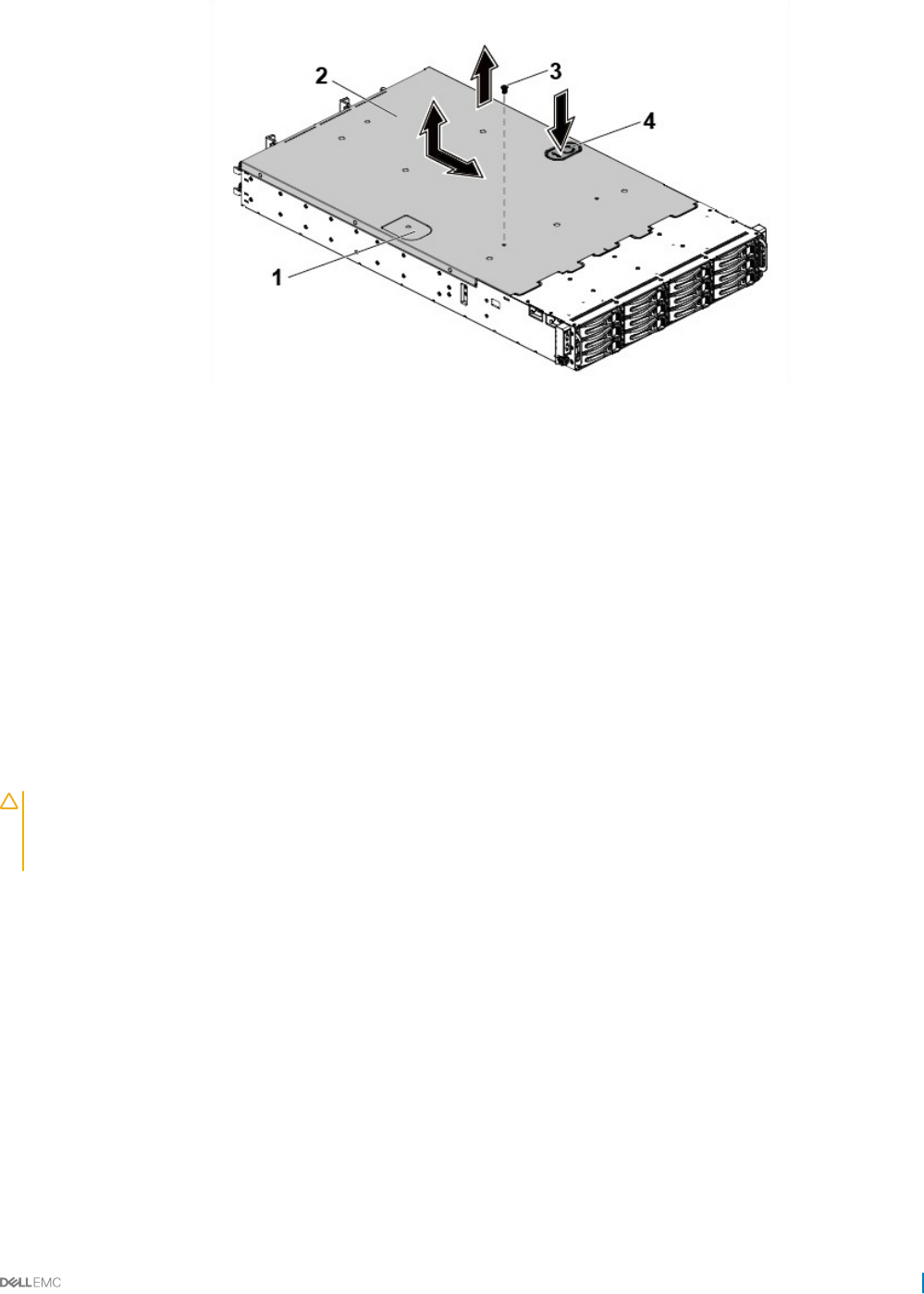
Figure 17. Removing and installing the system cover
1 traction pad 2 system cover
3 securing screw 4 cover release latch lock
Next steps
Install the system cover.
Related links
Safety instructions
Installing the system cover
Installing the system cover
Prerequisites
CAUTION: Many repairs may only be done by a certied service technician. You should only perform troubleshooting and simple
repairs as authorized in your product documentation, or as directed by the online or telephone service and support team. Damage
due to servicing that is not authorized by Dell is not covered by your warranty. Read and follow the safety instructions that are
shipped with your product.
Follow the safety guidelines listed in the Safety instructions section.
Steps
1 Place the system cover on the chassis and slide it to the front of the chassis until it snaps into place.
2 Secure the cover with the securing screw.
Next steps
1 Reconnect the system to the electrical outlet.
2 Turn on the system, including any attached peripherals.
Related links
Safety instructions
Installing and removing system components 59
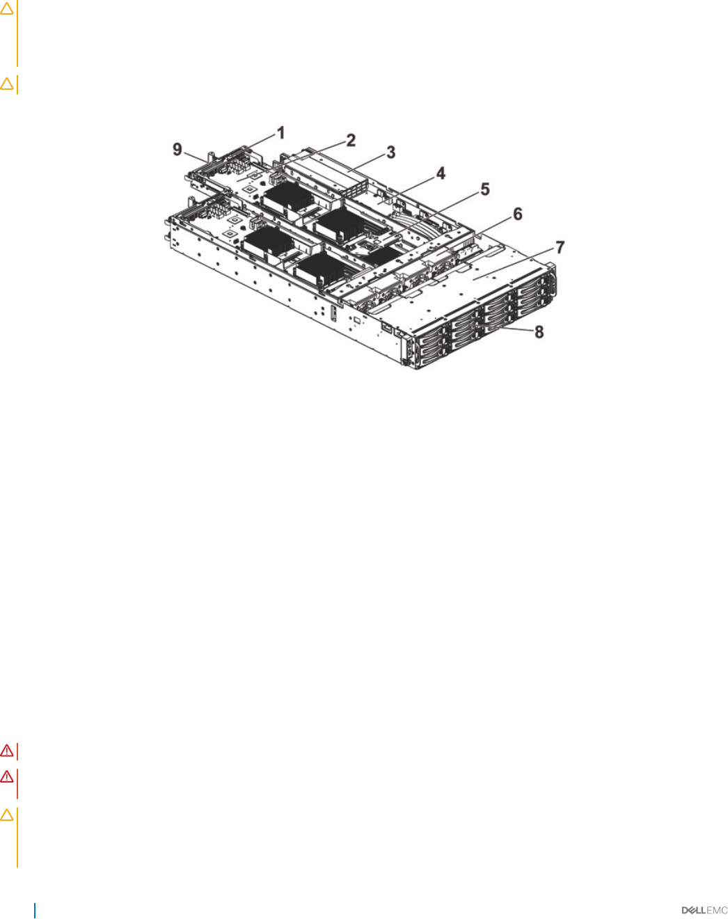
Inside the system
CAUTION: Many repairs may only be done by a certied service technician. You should only perform troubleshooting and simple
repairs as authorized in your product documentation, or as directed by the online or telephone service and support team. Damage
due to servicing that is not authorized by Dell is not covered by your warranty. Read and follow the safety instructions that are
shipped with your product.
CAUTION: This system must be operated with the system cover installed to ensure proper cooling.
Figure 18. Inside the system
1mezzanine card bracket 2 system board assembly (4)
3 power supply unit (2) 4 power distribution board (2)
5 Battery backup unit (BBU) bracket 6 cooling fan (4)
7 hard-drive bay 8 hard drive (12)
9 riser card bracket
Cooling fans
Servers use a lot of power to function, and that in turn generates a lot of heat. That heat, without a system in place to dissipate it, can
destroy the mechanical parts and damage the server. In most cases, the simplest and most ecient way to dissipate this heat is through
the use of fans.
Removing a cooling fan
Prerequisites
WARNING: Do not attempt to operate the system without the cooling fans.
WARNING: The cooling fan can continue to spin for some time after the system has been powered down. Allow time for the fan
to stop spinning before removing it from the system.
CAUTION: Many repairs may only be done by a certied service technician. You should only perform troubleshooting and simple
repairs as authorized in your product documentation, or as directed by the online or telephone service and support team. Damage
due to servicing that is not authorized by Dell is not covered by your warranty. Read and follow the safety instructions that are
shipped with your product.
60 Installing and removing system components
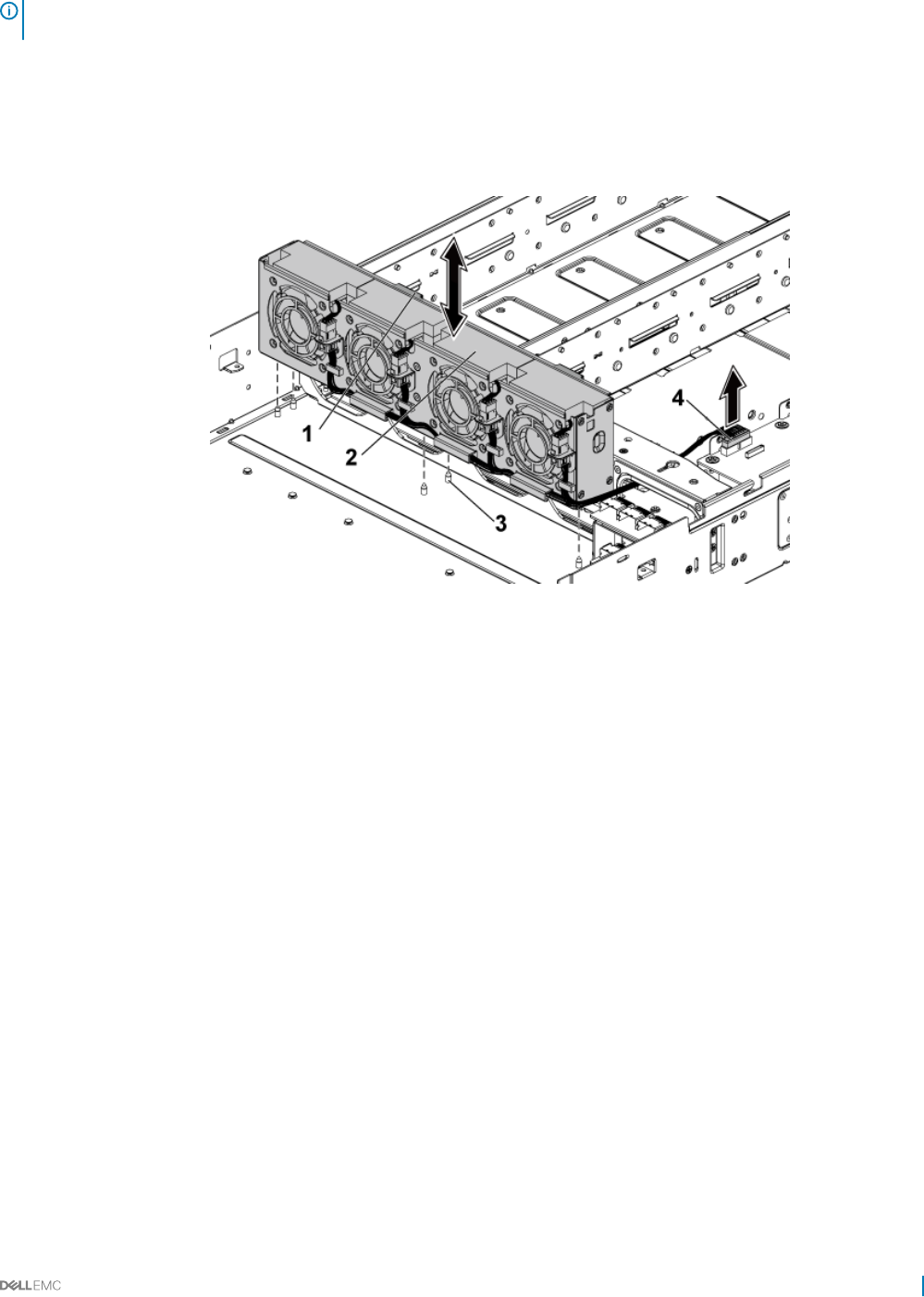
NOTE: Observe the routing of the cable through the cable tie as you remove them from the system. You must route these cables
properly when you replace them to prevent the cables from being pinched or crimped.
1 Follow the safety guidelines listed in the Safety instructions section.
2 Follow the procedure listed in the Before working inside your system section.
Steps
1 Disconnect the fan’s power cable from the power distribution board 1.
2 Lift the cooling fan cage out of the chassis.
Figure 19. Removing and installing a cooling fan cage
1locking clips (2) 2 cooling fan cage
3 locating pin (6) 4 power connector
3 Disconnect the fan cable from the fan connector on the cooling fan cage.
4 Lift the cooling fan with the sponge out of the cooling fan cage.
Installing and removing system components 61
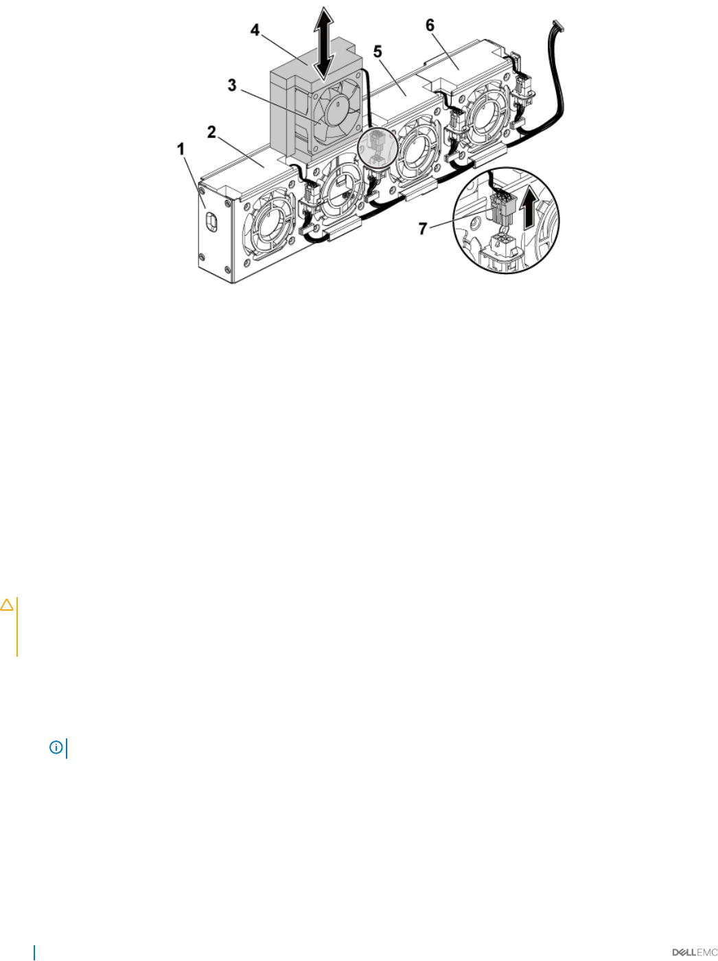
Figure 20. Removing and installing a cooling fan
1 cooling-fan cage 2 cooling fan 1
3 cooling fan 2 4 sponge
5 cooling fan 3 6 cooling fan 4
7 fan cable
Related links
Safety instructions
Removing the system cover
Before working inside your system
Installing a cooling fan
Prerequisites
CAUTION: Many repairs may only be done by a certied service technician. You should only perform troubleshooting and simple
repairs as authorized in your product documentation, or as directed by the online or telephone service and support team. Damage
due to servicing that is not authorized by Dell is not covered by your warranty. Read and follow the safety instructions that are
shipped with your product.
Follow the safety guidelines listed in the Safety instructions section.
Steps
1 Align the cooling fan with the sponge and slide it in the cooling-fan cage until the cooling fan is rmly seated.
NOTE: The fan blades should face the control panel of the system.
2 Connect the fan cable to the connector on the cooling-fan cage.
3 Align the cooling-fan cage with the locating pins on the chassis and place it into the chassis until it is rmly seated in place.
4 Connect the fan’s power cable to the connector on the power distribution board 1.
You must route these cables properly through the ties to prevent them from being pinched or crimped.
Next steps
1 Follow the procedure listed in the After working inside your system section.
2 Check the management software to see if the fan is rotating at the optimal speed.
62 Installing and removing system components

Related links
Safety instructions
After working inside your system
Hard drives
A hard drive is a data storage device used for storing and retrieving digital information by using one or more rigid rapidly rotating disks
(platters) coated with magnetic material.
CAUTION: Use only hard drives that have been tested and approved for use with the SAS/SATA backplane.
The following are the recommended guidelines for installing a mix of SAS hard drives, SATA hard drives, and SSDs:
• Only two drive types can be mixed per node.
• Drives 0 and 1 must be of same type.
• The remaining drives must all be the same type.
• SAS hard drive support is based on the add-on card and the onboard conguration supports SATA hard drive only.
Removing a 3.5-inch hard drive blank
Prerequisites
CAUTION: Many repairs may only be done by a certied service technician. You should only perform troubleshooting and simple
repairs as authorized in your product documentation, or as directed by the online or telephone service and support team. Damage
due to servicing that is not authorized by Dell is not covered by your warranty. Read and follow the safety instructions that are
shipped with your product.
CAUTION: To maintain proper system cooling, all empty hard drive bays must have drive blanks installed.
NOTE: This section is applicable to systems with hot swappable hard drives only.
Follow the safety guidelines listed in the Safety instructions section.
Steps
Pull the hard drive blank out of the hard drive bay.
Installing and removing system components 63
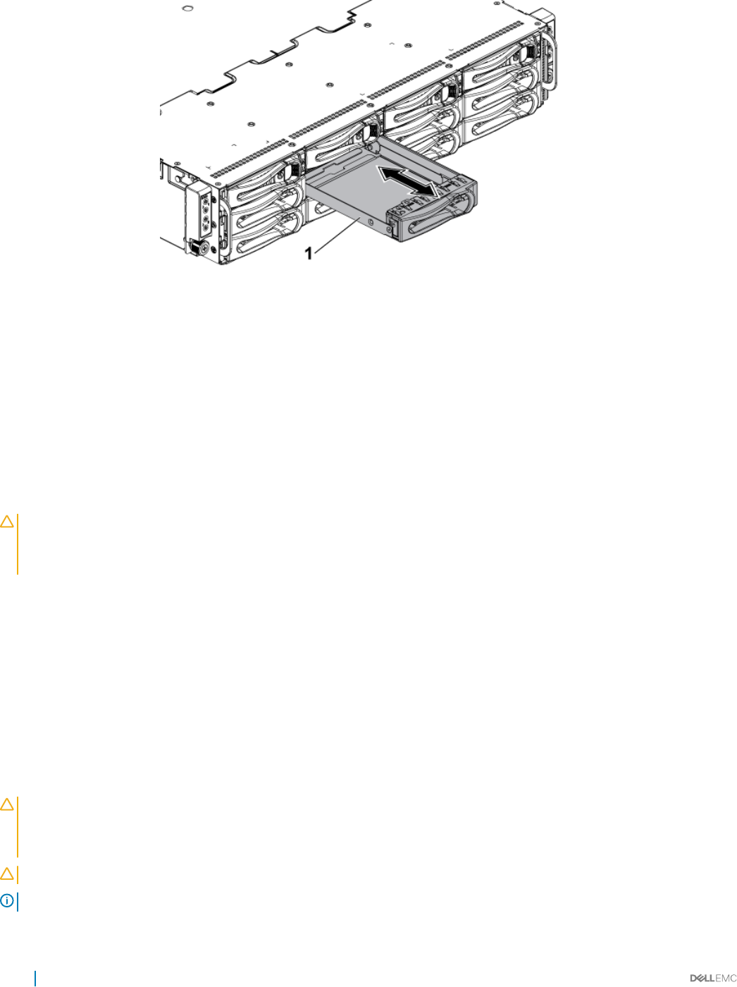
Figure 21. Removing or installing a 3.5-inch hard drive blank
1 3.5-inch hard drive blank
Related links
Safety instructions
Installing a 3.5-inch hard drive blank
Prerequisites
CAUTION: Many repairs may only be done by a certied service technician. You should only perform troubleshooting and simple
repairs as authorized in your product documentation, or as directed by the online or telephone service and support team. Damage
due to servicing that is not authorized by Dell is not covered by your warranty. Read and follow the safety instructions that are
shipped with your product.
Follow the safety guidelines listed in the Safety instructions section.
Steps
Slide the hard drive blank into the drive bay until the hard drive blank is seated in place.
Related links
Safety instructions
Removing a 2.5-inch hard drive blank
Prerequisites
CAUTION: Many repairs may only be done by a certied service technician. You should only perform troubleshooting and simple
repairs as authorized in your product documentation, or as directed by the online or telephone service and support team. Damage
due to servicing that is not authorized by Dell is not covered by your warranty. Read and follow the safety instructions that are
shipped with your product.
CAUTION: To maintain proper system cooling, all empty hard drive bays must have drive blanks installed.
NOTE: This section is applicable to systems with hot swappable hard drives only.
64 Installing and removing system components
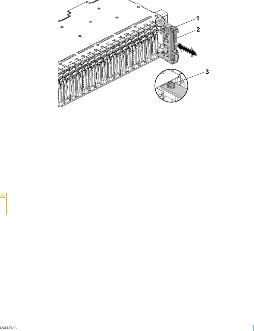
Follow the safety guidelines listed in the Safety instructions section.
Steps
Pull the handle to remove the 2.5-inch hard drive blank out of the hard drive bay.
Figure 22. Removing or installing a 2.5-inch hard drive blank
12.5-inch hard drive blank 2 handle
3 latch
Related links
Safety instructions
Installing a 2.5-inch hard drive blank
Prerequisites
CAUTION: Many repairs may only be done by a certied service technician. You should only perform troubleshooting and simple
repairs as authorized in your product documentation, or as directed by the online or telephone service and support team. Damage
due to servicing that is not authorized by Dell is not covered by your warranty. Read and follow the safety instructions that are
shipped with your product.
Follow the safety guidelines listed in the Safety instructions section.
Steps
1 With the latch facing up, slide the latch into the hard drive bay.
2 Push the 2.5-inch hard drive with a slight inclination into the hard drive bay until the hard drive blank is seated in place.
Related links
Safety instructions
Installing and removing system components 65
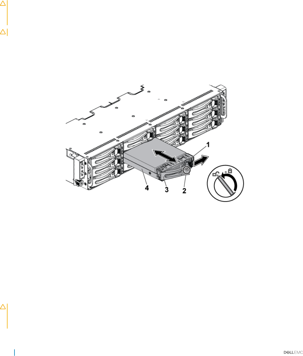
Removing a hard drive
The installation and removal procedures for the 3.5-inch hard drive and the 2.5-inch hard drive are similar.
Prerequisites
CAUTION: Many repairs may only be done by a certied service technician. You should only perform troubleshooting and simple
repairs as authorized in your product documentation, or as directed by the online or telephone service and support team. Damage
due to servicing that is not authorized by Dell is not covered by your warranty. Read and follow the safety instructions that are
shipped with your product.
CAUTION: To maintain proper system cooling, all empty hard drive bays must have drive blanks installed.
Follow the safety guidelines listed in the Safety instructions section.
Steps
1 Turn the lock lever counterclockwise until it points to the unlock symbol.
2 Slide the release button to open the release handle.
3 Using the release handle, pull the hard drive carrier out of the hard drive bay.
Figure 23. Removing and installing a hard drive
1release button 2 lock lever
3 release handle 4 hard drive carrier
Related links
Safety instructions
Installing a hard drive
Prerequisites
CAUTION: Many repairs may only be done by a certied service technician. You should only perform troubleshooting and simple
repairs as authorized in your product documentation, or as directed by the online or telephone service and support team. Damage
due to servicing that is not authorized by Dell is not covered by your warranty. Read and follow the safety instructions that are
shipped with your product.
66 Installing and removing system components
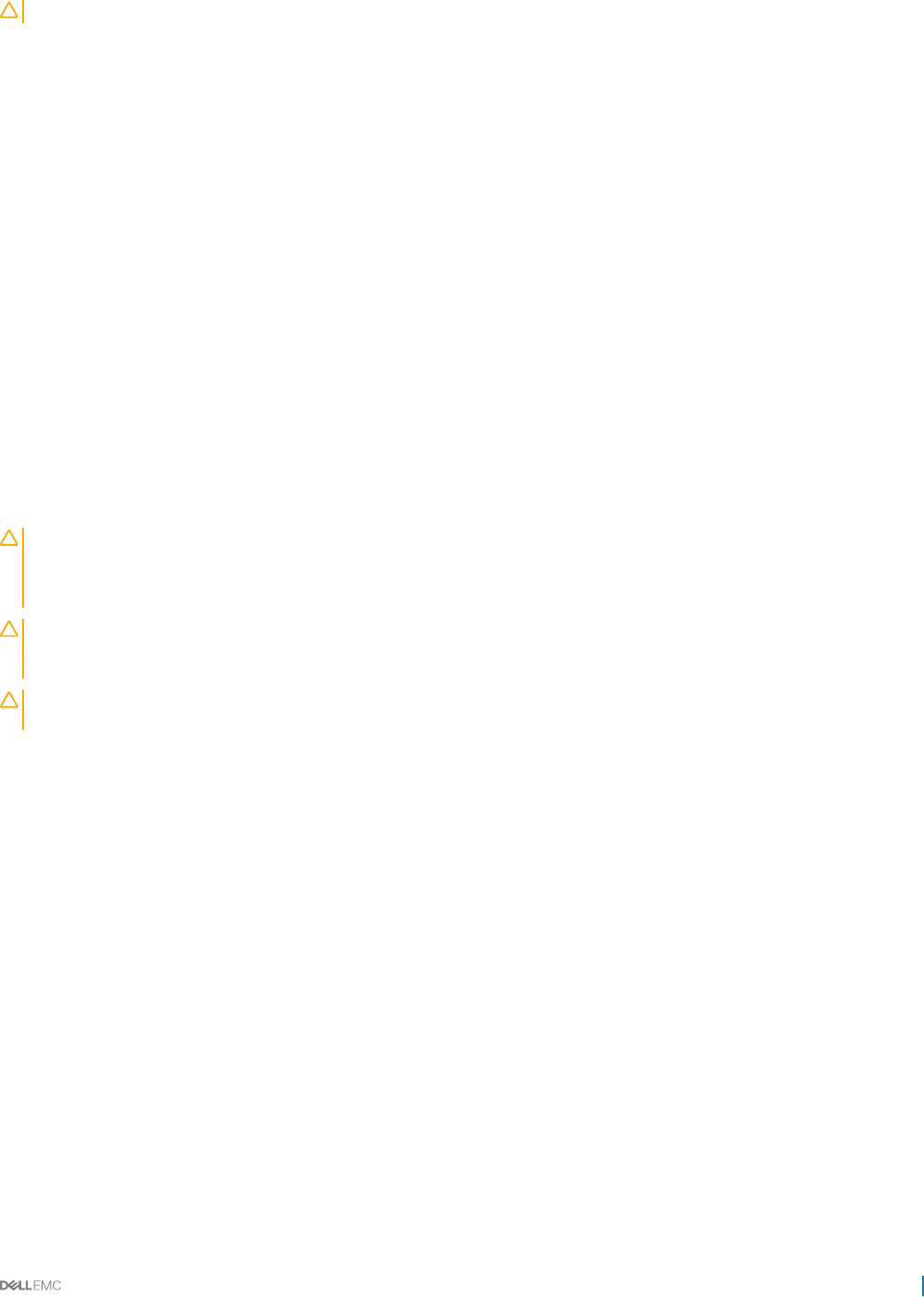
CAUTION: To maintain proper system cooling, all empty hard drive bays must have drive blanks installed.
Follow the safety guidelines listed in the Safety instructions section.
Steps
1 With the lever on the hard drive carrier open, slide the hard drive carrier into the drive bay until the hard drive connector engages with
the backplane.
2 Close the release handle to lock the hard drive in place.
3 Turn the lock lever clockwise to the lock symbol.
Next steps
1 To check the status of the hard drive, see the hard drive activity and status indicators. For more information, see the Hard drive
indicator patterns section.
2 Check the management software to verify the status of the installed hard drive.
Related links
Safety instructions
Hard drive indicator patterns
Removing a hard drive from a hard drive carrier
Prerequisites
CAUTION: Many repairs may only be done by a certied service technician. You should only perform troubleshooting and simple
repairs as authorized in your product documentation, or as directed by the online or telephone service and support team. Damage
due to servicing that is not authorized by Dell is not covered by your warranty. Read and follow the safety instructions that are
shipped with your product.
CAUTION: When installing a hard drive carrier, ensure that the adjacent drives are fully installed. Inserting a hard drive carrier
and attempting to lock its handle next to a partially installed carrier can damage the partially installed carrier's shield spring and
make it unusable.
CAUTION: To prevent data loss, ensure that your operating system supports hot-swappable drive installation. See the
documentation supplied with the operating system.
Follow the safety guidelines listed in the Safety instructions section.
Steps
1 Remove the screws.
2 Lift the hard drive out of the hard drive carrier.
Installing and removing system components 67
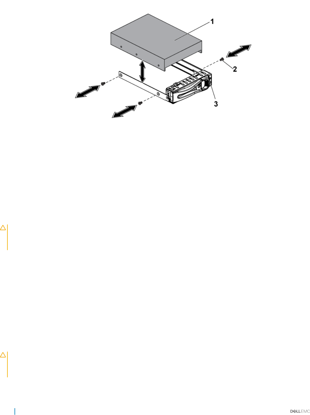
Figure 24. Removing and installing a hard drive from the hard drive carrier
1 hard drive 2 screw (4)
3 hard drive carrier
Related links
Safety instructions
Installing a hard drive into a hard drive carrier
Prerequisites
CAUTION: Many repairs may only be done by a certied service technician. You should only perform troubleshooting and simple
repairs as authorized in your product documentation, or as directed by the online or telephone service and support team. Damage
due to servicing that is not authorized by Dell is not covered by your warranty. Read and follow the safety instructions that are
shipped with your product.
Follow the safety guidelines listed in the Safety instructions section.
Steps
1 Place the hard drive into the hard drive carrier.
2 Secure the hard drive to the hard drive carrier with screws.
Related links
Safety instructions
Installing a 2.5-inch SSD into a 3.5-inch hard drive carrier
Prerequisites
CAUTION: Many repairs may only be done by a certied service technician. You should only perform troubleshooting and simple
repairs as authorized in your product documentation, or as directed by the online or telephone service and support team. Damage
due to servicing that is not authorized by Dell is not covered by your warranty. Read and follow the safety instructions that are
shipped with your product.
68 Installing and removing system components
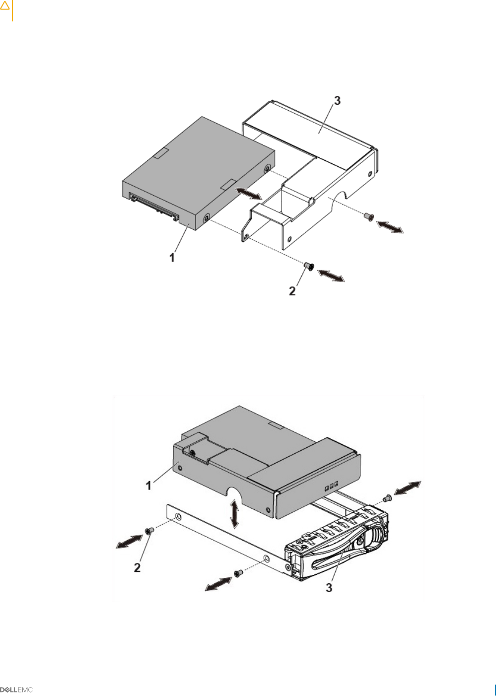
CAUTION: This removal and installation procedure is only for 2.5-inch SSD. Installing a 2.5-inch hard disk drive into the adapter
can cause performance issue.
Follow the safety guidelines listed in the Safety instructions section.
Steps
1 Place the 2.5-inch SSD into the 2.5-inch adapter bracket.
2 Secure the 2.5-inch SSD to the 2.5-inch adapter bracket with M3 screws.
Figure 25. Removing and installing a 2.5-inch SSD from the 2.5-inch adapter bracket
12.5-inch SSD 2 M3 screw (2)
3 2.5-inch adapter
3 Place the adapter assembly into the 3.5-inch hard drive carrier.
4 Secure the adapter assembly to the 3.5-inch hard drive carrier with screws.
Figure 26. Removing and installing an adapter assembly from the hard drive carrier
1adapter assembly 2 screw (3)
Installing and removing system components 69
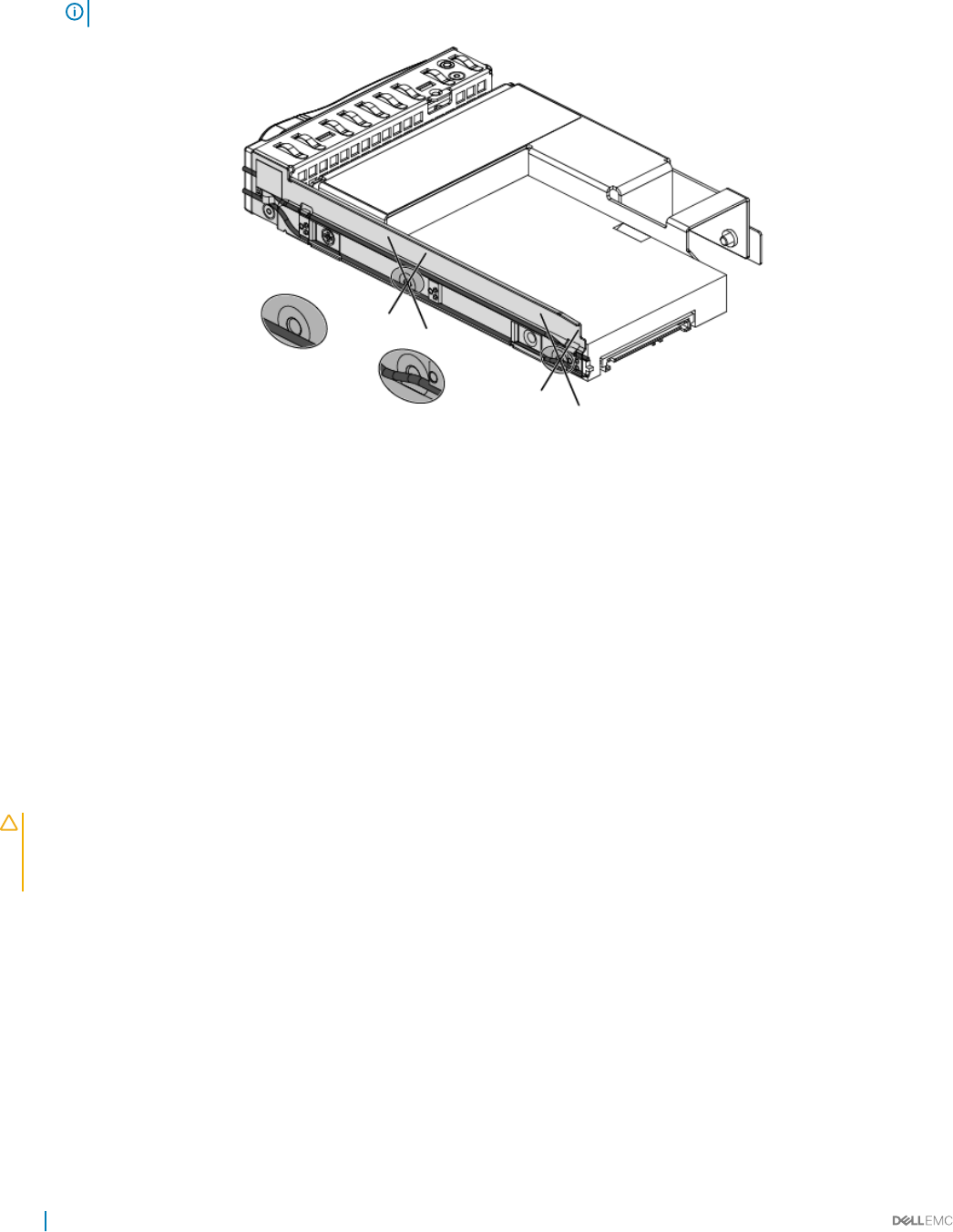
3 hard drive carrier
NOTE: Do not install screws in the screw holes on the side of SSD, which are occupied by the light pipe.
Figure 27. Screw holes on the side of SSD occupied by the light pipe
Related links
Safety instructions
SSD and SSD holder
A solid-state drive (SSD, also known as a solid-state disk although it contains neither an actual disk nor a drive motor to spin a disk) is a
solid-state storage device that uses integrated circuit assemblies as memory to store data persistently. SSDs have no moving (mechanical)
components. SSDs are typically more resistant to physical shock, run silently, have lower access time, and less latency.
Removing the SSD and SSD Holder
Prerequisites
CAUTION: Many repairs may only be done by a certied service technician. You should only perform troubleshooting and simple
repairs as authorized in your product documentation, or as directed by the online or telephone service and support team. Damage
due to servicing that is not authorized by Dell is not covered by your warranty. Read and follow the safety instructions that are
shipped with your product.
1 Follow the safety guidelines listed in the Safety instructions section.
2 Turn o the system, including any attached peripherals.
3 Disconnect the system from the electrical outlet and disconnect the peripherals.
4 Remove the system board assembly.
Steps
1 Disconnect the MicroSATA cables from the system board.
2 Slide the SSD with the MicroSATA cable out of the SSD holder.
70 Installing and removing system components
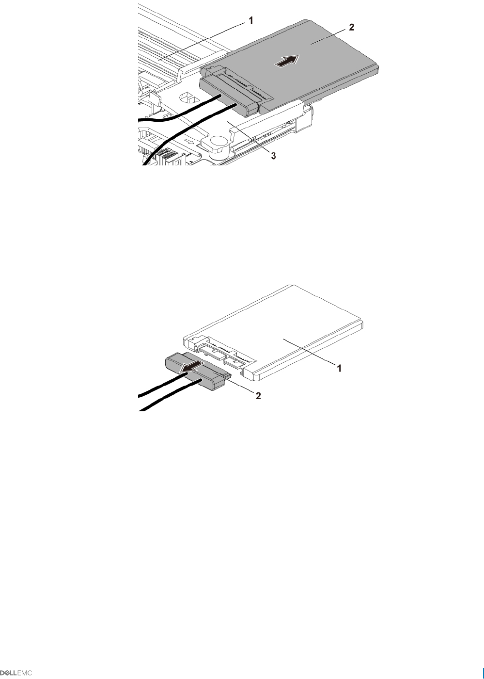
Figure 28. Removing the SSD with MicroSATA cable
1 system-board assembly 2 SSD with MicroSATA cable
3 SSD holder
3 Disconnect the MicroSATA cable from the SSD.
Figure 29. Removing the MicroSATA cable
1SSD 2 MicroSATA cable
4 Remove the screw that secures the SSD holder to the battery backup unit (BBU) bracket.
5 Remove the SSD holder from the BBU bracket.
Installing and removing system components 71
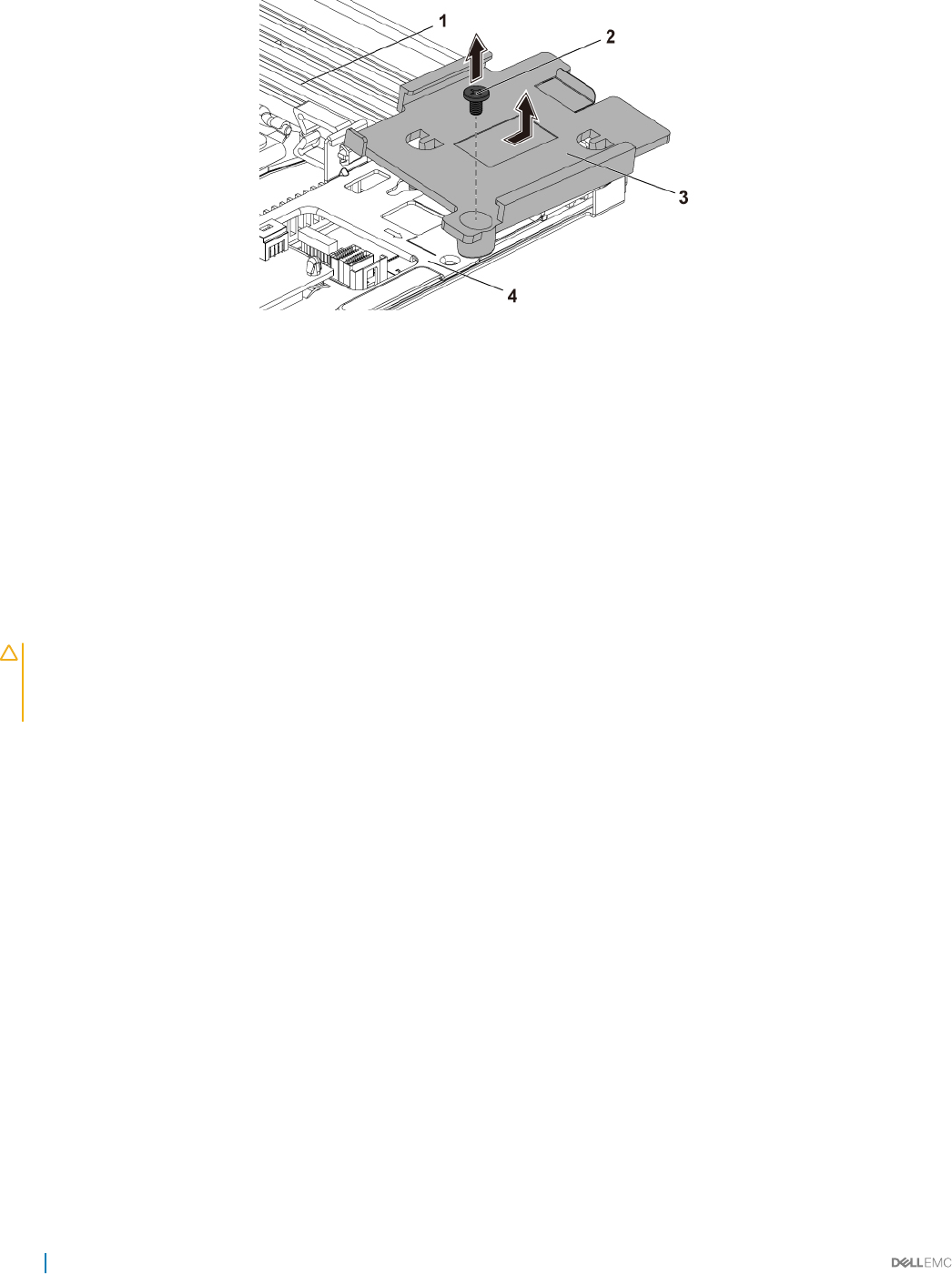
Figure 30. Removing the SSD Holder
1 system-board assembly 2 screw
3 SSD holder 4 BBU Bracket
Related links
Safety instructions
Removing the system board assembly
Installing the SSD and SSD holder
Prerequisites
CAUTION: Many repairs may only be done by a certied service technician. You should only perform troubleshooting and simple
repairs as authorized in your product documentation, or as directed by the online or telephone service and support team. Damage
due to servicing that is not authorized by Dell is not covered by your warranty. Read and follow the safety instructions that are
shipped with your product.
Follow the safety guidelines listed in the Safety instructions section.
Steps
1 Place the SSD holder on the battery backup unit (BBU) bracket.
2 Replace the screw that secures the SSD holder to the BBU bracket.
3 Connect the MicroSATA cable to the SSD.
4 Slide the SSD with the MicroSATA cable into the SSD holder.
5 Reconnect all the cables.
Next steps
1 Install the system board assembly.
2 Reconnect the peripherals and connect the system to the electrical outlet.
3 Turn on the system, including any attached peripherals.
Related links
Safety instructions
Installing the system board assembly
72 Installing and removing system components
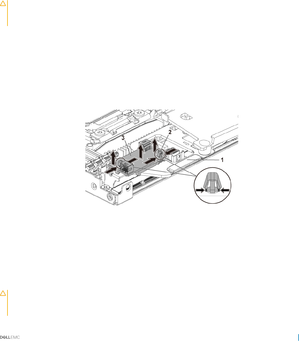
DC to DC board
DC to DC board is a power regulating board that supplies power to the 1.8 inch SSD.
Removing the DC to DC board
Prerequisites
CAUTION: Many repairs may only be done by a certied service technician. You should only perform troubleshooting and simple
repairs as authorized in your product documentation, or as directed by the online or telephone service and support team. Damage
due to servicing that is not authorized by Dell is not covered by your warranty. Read and follow the safety instructions that are
shipped with your product.
1 Follow the safety guidelines listed in the Safety instructions section.
2 Turn o the system, including any attached peripherals.
3 Disconnect the system from the electrical outlet and disconnect the peripherals.
4 Remove the system board assembly.
Steps
1 Disconnect all the cables.
2 Press the space support by using clamper, and lift one side of the DC to DC board.
3 Repeat step 2 for the other space support, and lift the other side of the DC to DC board.
4 Remove the DC to DC board out of the BBU bracket.
Figure 31. Removing the DC to DC board
1BBU Bracket 2 Space support (2)
3 DC to DC board
Installing the DC to DC board
Prerequisites
CAUTION: Many repairs may only be done by a certied service technician. You should only perform troubleshooting and simple
repairs as authorized in your product documentation, or as directed by the online or telephone service and support team. Damage
due to servicing that is not authorized by Dell is not covered by your warranty. Read and follow the safety instructions that are
shipped with your product.
Installing and removing system components 73
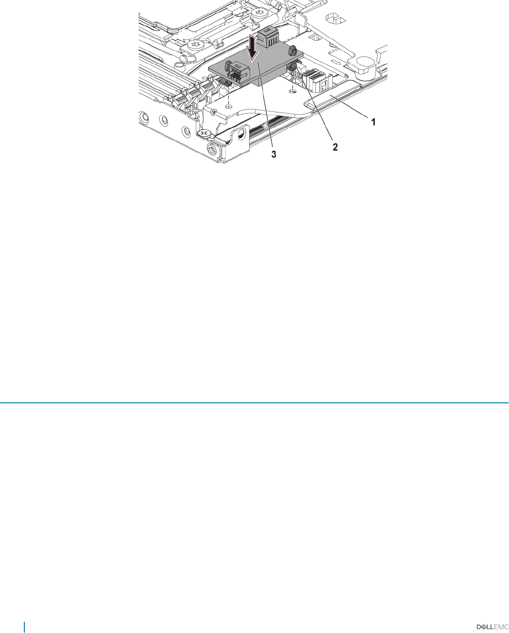
Follow the safety guidelines listed in the Safety instructions section.
Steps
1 Align the space supports with the holes on the BBU bracket, and press the DC to DC board until the retaining clips ip.
Figure 32. Installing the DC to DC board
1 BBU Bracket 2 space support (2)
3 DC to DC board
2 Reconnect all the cables.
Next steps
1 Install the system board.
2 Reconnect the peripherals and connect the system to the electrical outlet.
3 Turn on the system, including any attached peripherals.
Cable routings for SSD and DC to DC board and LSI 2008
Table 24. Cable routings for SSD and DC to DC Board and LSI 2008
Item Cable From (LSI 2008 SAS Mezzanine card) To (System board)
1 Mini-SAS cable Mini-SAS connector 4-7 (J4)
On LSI 2008 SAS Mezzanine Card
SAS/SATA connectors 4&5
2Mini-SAS connector 0 - 3 (J3)
On LSI 2008 SAS Mezzanine Card
Mini-SAS HD Connector 0-3
3 MicroSATA cable 1.8-inch SSD Onboard SATA Connector 5 on the system
board
4 1.8-inch SSD DC to DC board (J2)
5 1x4 power cable DC to DC to DC board (J1) High Power Connector on the system board
74 Installing and removing system components
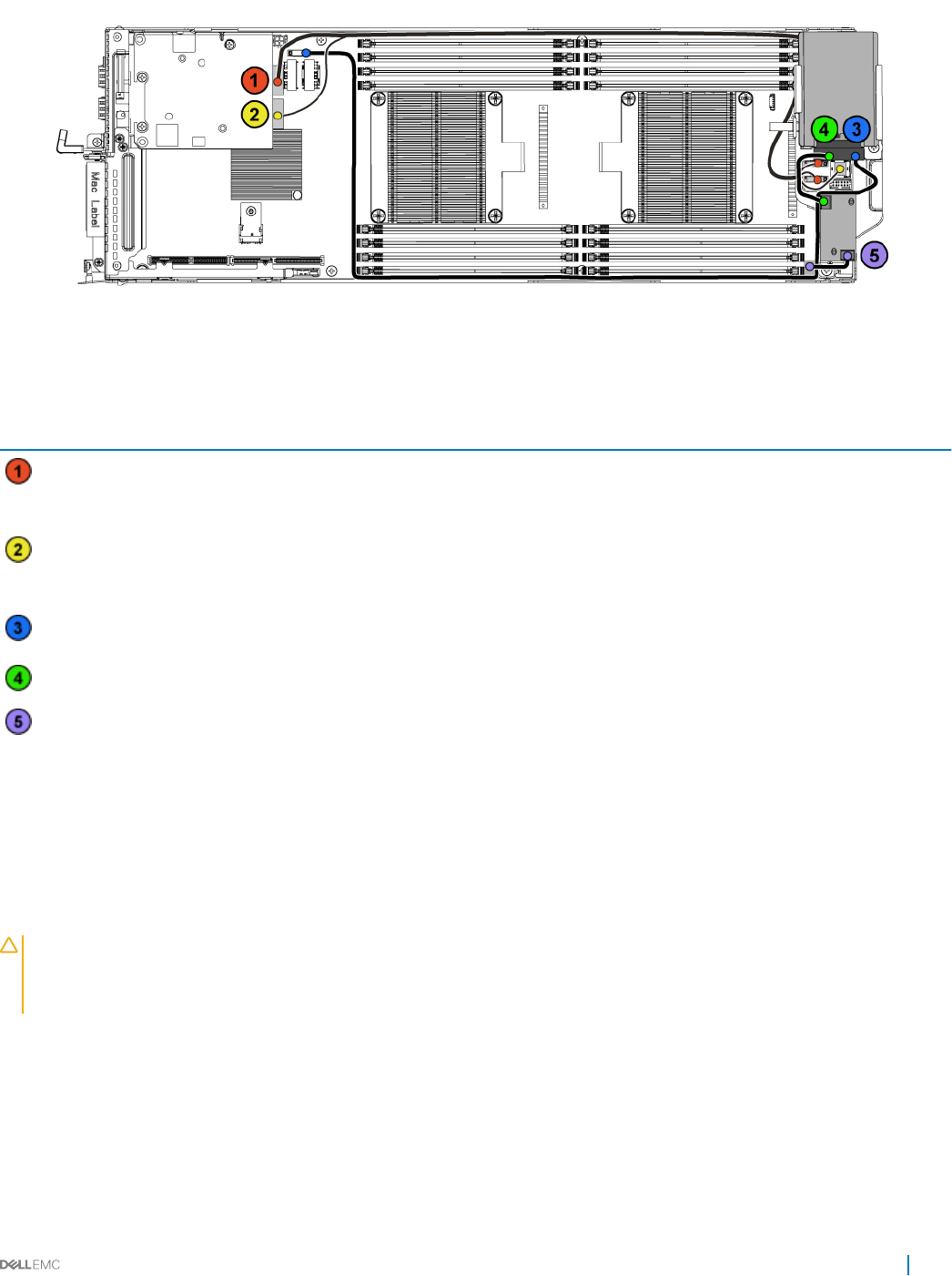
Figure 33. Cable routings for SSD and DC to DC Board and LSI 2008
Table 25. Cable routings for SSD and DC to DC Board and LSI 2008
Item Cable From (LSI 2008 SAS Mezzanine card) To (System board)
Mini-SAS cable Mini-SAS connector 4-7 (J4)
On LSI 2008 SAS Mezzanine Card
SAS/SATA connectors 4&5
Mini-SAS connector 0-3 (J3)
On LSI 2008 SAS Mezzanine Card
Mini-SAS HD Connector 0-3
MicroSATA cable 1.8-inch SSD Onboard SATA Connector 5 on the system
board
1.8-inch SSD DC to DC board (J2)
1x4 power cable DC to DC to DC board (J1) High Power Connector on the system board
SATADOM
Removing the SATADOM
Prerequisites
CAUTION: Many repairs may only be done by a certied service technician. You should only perform troubleshooting and simple
repairs as authorized in your product documentation, or as directed by the online or telephone service and support team. Damage
due to servicing that is not authorized by Dell is not covered by your warranty. Read and follow the safety instructions that are
shipped with your product.
1 Follow the safety guidelines listed in the Safety instructions section.
2 Turn o the system, including any attached peripherals.
3 Disconnect the system from the electrical outlet and disconnect the peripherals.
Steps
1 Disconnect the power cable from the SATADOM and the system board.
2 Using a screwdriver, press the metal latch to release the SATADOM.
Installing and removing system components 75
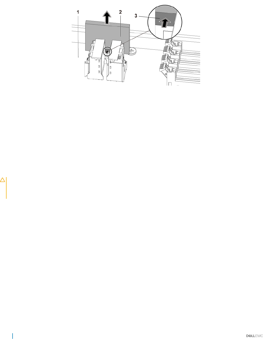
3 Holding the SATADOM by its edges, pull the SATADOM until the card edge connector disengages from the onboard SATA connector 5
on the system board.
Figure 34. Removing the SATADOM
1 system board assembly 2 SATADOM
3 metal latch
Related links
Safety instructions
Removing the system board assembly
Installing the SATADOM
Prerequisites
CAUTION: Many repairs may only be done by a certied service technician. You should only perform troubleshooting and simple
repairs as authorized in your product documentation, or as directed by the online or telephone service and support team. Damage
due to servicing that is not authorized by Dell is not covered by your warranty. Read and follow the safety instructions that are
shipped with your product.
Follow the safety guidelines listed in the Safety instructions section.
Steps
1 Holding the SATADOM by its edges, position it so that the card edge connector aligns with the onboard SATA connector 5 on the
system board.
2 Press the SATADOM with your thumbs until it is fully seated.
3 Reconnect all the cables.
Next steps
1 Reconnect the peripherals and connect the system to the electrical outlet.
2 Turn on the system, including any attached peripherals.
Related links
Safety instructions
Installing the system board assembly
76 Installing and removing system components
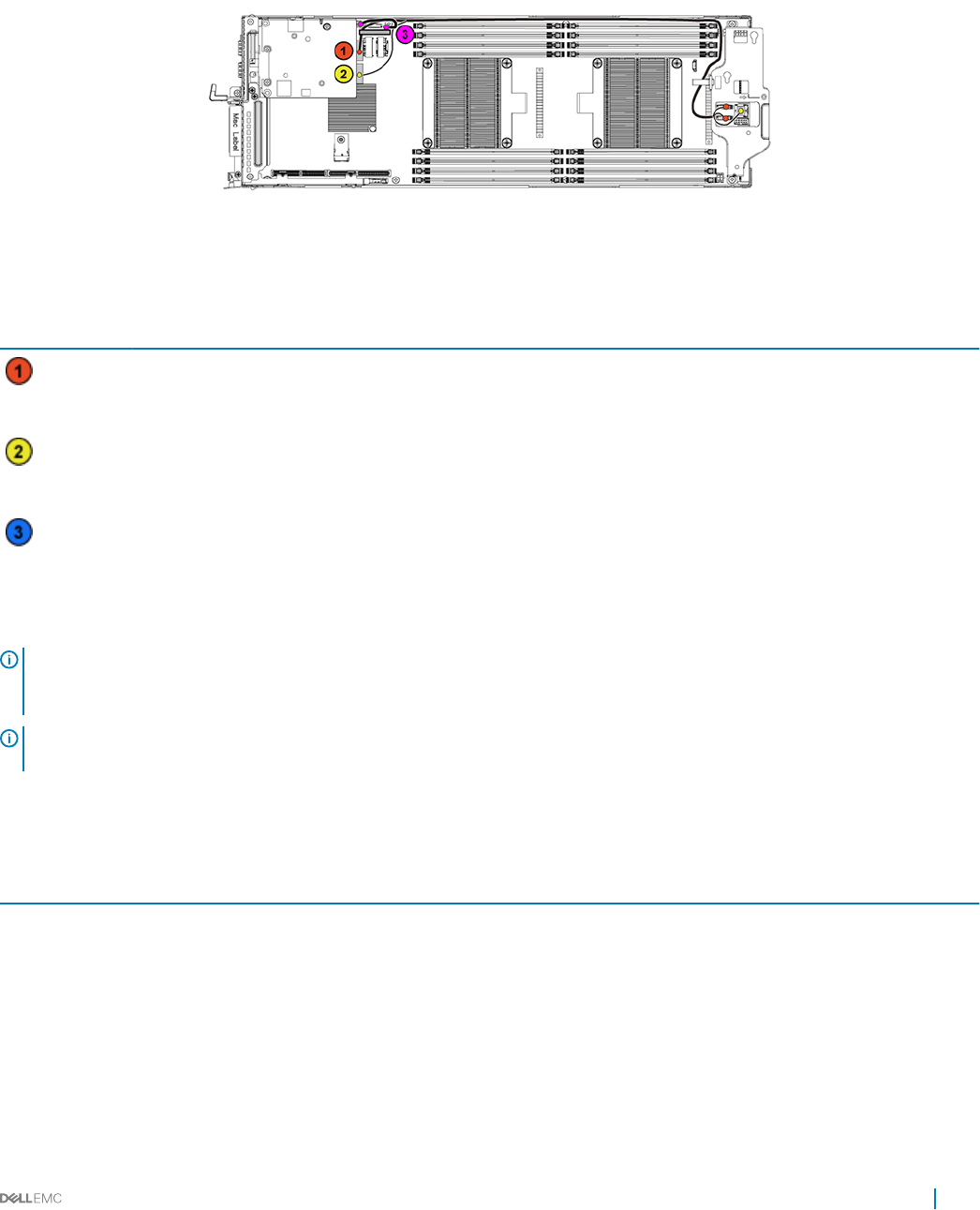
Cable routing for SATADOM and LSI 2008
Figure 35. Cable Routing for SATADOM and LSI 2008
Table 26. Cable Routing for SATADOM and LSI 2008
Item Cable From (LSI 2008 SAS Mezzanine Card) To (System Board)
Mini-SAS cable Mini-SAS connector 4-7 (J4)
On LSI 2008 SAS Mezzanine Card
SAS/SATA connectors 4&5
Mini-SAS connector 0-3 (J3)
On LSI 2008 SAS Mezzanine Card
Mini-SAS HD Connector 0-3
SATADOM power
cable
SATADOM HDD Power Connector on the system board
Power supply units
NOTE: Congurations higher than indicated in the table may change the PSU mode to non-redundant. In non-redundant mode if
the power requirement exceeds the installed system power capacity, the BIOS will throttle the processors. Also, since Processor
Power Capping is enabled, processor throttling occurs on congurations that exceed the cap value.
NOTE: Both the PSUs are hot swappable, and they can support hot swap in any condition if the system has power throttling
feature.
The following table lists the maximum supported conguration where power supply unit (PSU) redundancy is guaranteed:
Table 27. PSUs conguration
PSU Four system boards
1400 W Up to two 120 W processor per system board, three hard drives per system board, and four memory modules per
system board
1600 W Up to two 120 W processor per system board, three hard drivesper system board, and eight memory modulesper
system board
Installing and removing system components 77
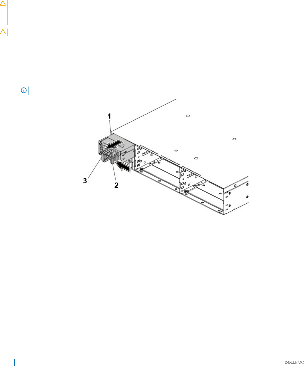
Removing a power supply unit
Prerequisites
CAUTION: Many repairs may only be done by a certied service technician. You should only perform troubleshooting and simple
repairs as authorized in your product documentation, or as directed by the online or telephone service and support team. Damage
due to servicing that is not authorized by Dell is not covered by your warranty. Read and follow the safety instructions that are
shipped with your product.
CAUTION: The system requires at least one power supply unit (PSU) to operate normally.
1 Follow the safety guidelines listed in the Safety instructions section.
2 Turn o the system, including any attached peripherals.
3 Disconnect the power cable from the power source and the PSU, and disconnect the peripherals.
Steps
Press the release lever and by using the handle, slide the PSU out of the system.
NOTE: Removing the PSU may require considerable force.
Figure 36. Removing and installing a PSU
1PSU 2 release lever
3 handle
Related links
Safety instructions
78 Installing and removing system components

Installing a power supply unit
Prerequisites
CAUTION: Many repairs may only be done by a certied service technician. You should only perform troubleshooting and simple
repairs as authorized in your product documentation, or as directed by the online or telephone service and support team. Damage
due to servicing that is not authorized by Dell is not covered by your warranty. Read and follow the safety instructions that are
shipped with your product.
CAUTION: The system requires at least one power supply unit (PSU) to operate normally.
Verify that both PSUs are of the same type and have the same maximum output power.
NOTE: The maximum output power is printed on the PSU label.
Follow the safety guidelines listed in the Safety instructions section.
Steps
Slide the new PSU into the chassis until the PSU until is fully seated and the release lever snaps into place.
Next steps
Connect the power cable to the PSU and plug the cable into a power outlet.
NOTE: When installing a new PSU in a system with two PSUs, allow several seconds for the system to recognize the PSU and
determine its status.
Related links
Safety instructions
System board tray
Removing the system board tray
Prerequisites
CAUTION: Many repairs may only be done by a certied service technician. You should only perform troubleshooting and simple
repairs as authorized in your product documentation, or as directed by the online or telephone service and support team. Damage
due to servicing that is not authorized by Dell is not covered by your warranty. Read and follow the safety instructions that are
shipped with your product.
Follow the safety guidelines listed in the Safety instructions section.
Steps
1 Remove the screw that secures the retaining latch.
2 Press the retaining latch and slide the system board tray out of the chassis.
Installing and removing system components 79
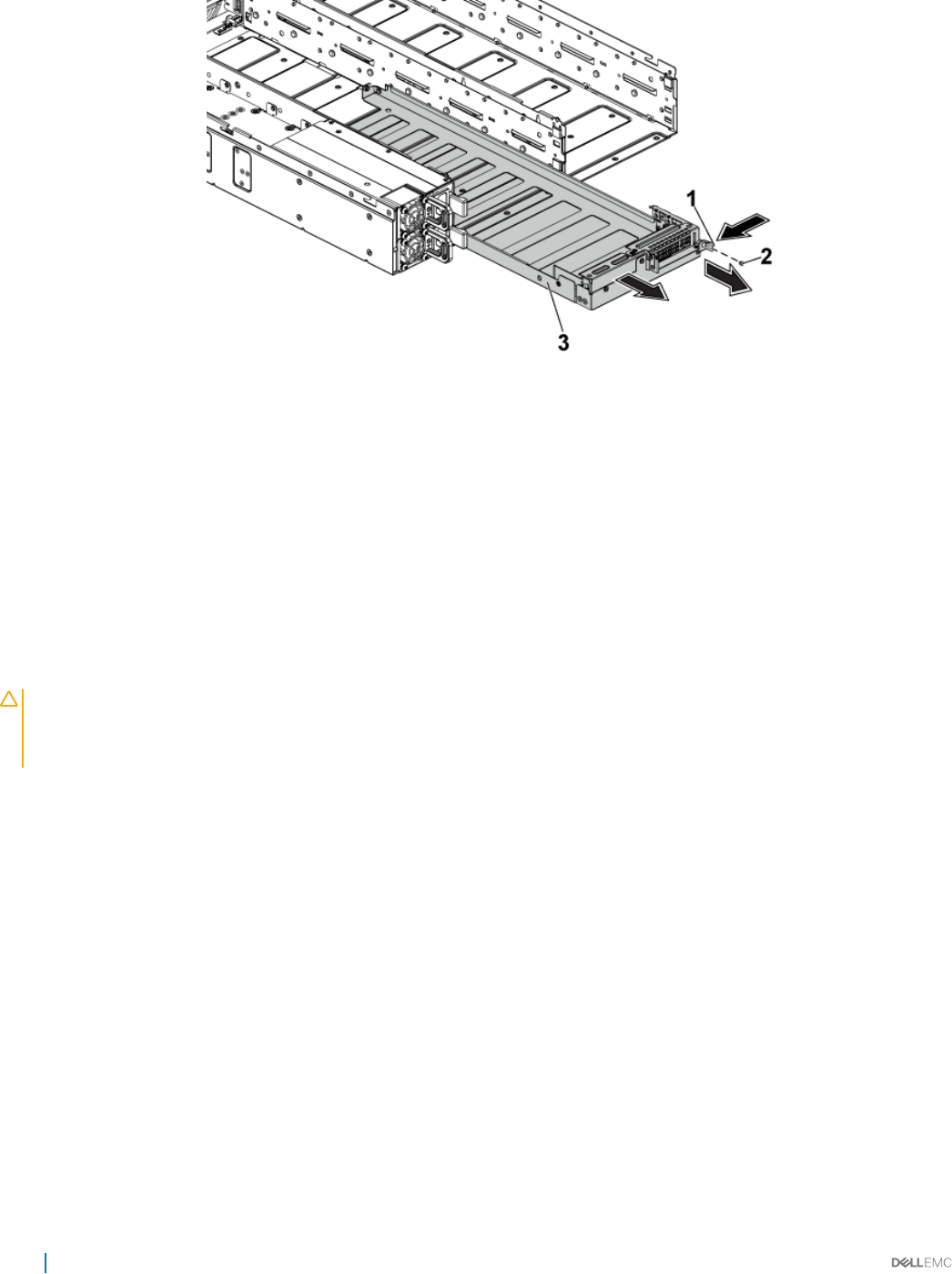
Figure 37. Removing and installing a system board tray
1 retaining latch 2 screw
3 system board tray
Related links
Safety instructions
Installing the system board tray
Prerequisites
CAUTION: Many repairs may only be done by a certied service technician. You should only perform troubleshooting and simple
repairs as authorized in your product documentation, or as directed by the online or telephone service and support team. Damage
due to servicing that is not authorized by Dell is not covered by your warranty. Read and follow the safety instructions that are
shipped with your product.
Follow the safety guidelines listed in the Safety instructions section.
Steps
1 Slide the system board tray into the chassis until it snaps into place.
2 Replace the screw that secures the retaining latch.
Related links
Safety instructions
80 Installing and removing system components
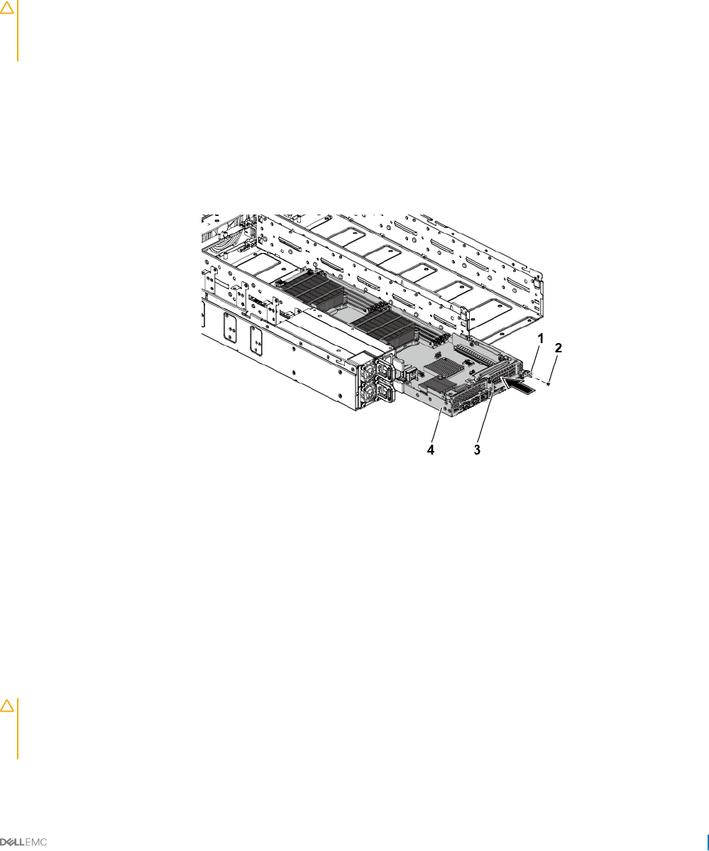
System board assembly
Removing the system board assembly
Prerequisites
CAUTION: Many repairs may only be done by a certied service technician. You should only perform troubleshooting and simple
repairs as authorized in your product documentation, or as directed by the online or telephone service and support team. Damage
due to servicing that is not authorized by Dell is not covered by your warranty. Read and follow the safety instructions that are
shipped with your product.
1 Follow the safety guidelines listed in the Safety instructions section.
2 Turn o the system, including any attached peripherals.
3 Disconnect the system from the electrical outlet and disconnect the peripherals.
4 Disconnect all the external cables from the system board.
Steps
1 Remove the screw that secures the retaining latch.
2 Press the retaining latch and by using the handle, slide the system board assembly out of the chassis.
Figure 38. Removing and installing a system board assembly
1retaining latch 2 screw
3 handle 4 system board assembly
Related links
Safety instructions
Installing the system board assembly
Prerequisites
CAUTION: Many repairs may only be done by a certied service technician. You should only perform troubleshooting and simple
repairs as authorized in your product documentation, or as directed by the online or telephone service and support team. Damage
due to servicing that is not authorized by Dell is not covered by your warranty. Read and follow the safety instructions that are
shipped with your product.
Follow the safety guidelines listed in the Safety instructions section.
Installing and removing system components 81

Steps
1 Slide the system board assembly into the chassis until it snaps into place.
2 Replace the screw that secures the retaining latch.
Next steps
1 Reconnect all the external cables to the system board.
2 Reconnect the peripherals and connect the system to the electrical outlet.
3 Turn on the system, including any attached peripherals.
NOTE: To add the service tag of the system board to match the service tag of the physical node, contact technical
support.
Related links
Safety instructions
Cooling shroud
The cooling shroud has aerodynamically placed openings that direct the airow across the entire system. The airow passes through all the
critical parts of the system, where the vacuum pulls air across the entire surface area of the heat sink, thus allowing increased cooling.
Removing the cooling shroud
Prerequisites
CAUTION: Many repairs may only be done by a certied service technician. You should only perform troubleshooting and simple
repairs as authorized in your product documentation, or as directed by the online or telephone service and support team. Damage
due to servicing that is not authorized by Dell is not covered by your warranty. Read and follow the safety instructions that are
shipped with your product.
1 Follow the safety guidelines listed in the Safety instructions section.
2 Turn o the system, including any attached peripherals.
3 Disconnect the system from the electrical outlet and disconnect the peripherals.
4 Remove the system board assembly.
Steps
Press the four latches along the direction of the arrows, and then lift the cooling shroud out of the system board assembly.
82 Installing and removing system components
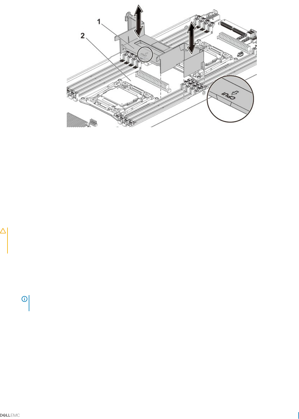
Figure 39. Removing the cooling shroud
1 cooling shroud 2 system board assembly
Related links
Safety instructions
Removing the system board assembly
Installing the cooling shroud
Prerequisites
CAUTION: Many repairs may only be done by a certied service technician. You should only perform troubleshooting and simple
repairs as authorized in your product documentation, or as directed by the online or telephone service and support team. Damage
due to servicing that is not authorized by Dell is not covered by your warranty. Read and follow the safety instructions that are
shipped with your product.
Follow the safety guidelines listed in the Safety instructions section.
Steps
Replace the cooling shroud into the system board assembly. Make sure that the four latches are properly engaged with the heat sink
bases and the latches click in place.
NOTE: When installing the cooling shroud, make sure the arrow of the mark on the cooling shroud points to processor 1,
and keep the at surface of the cooling shroud horizontal.
Installing and removing system components 83
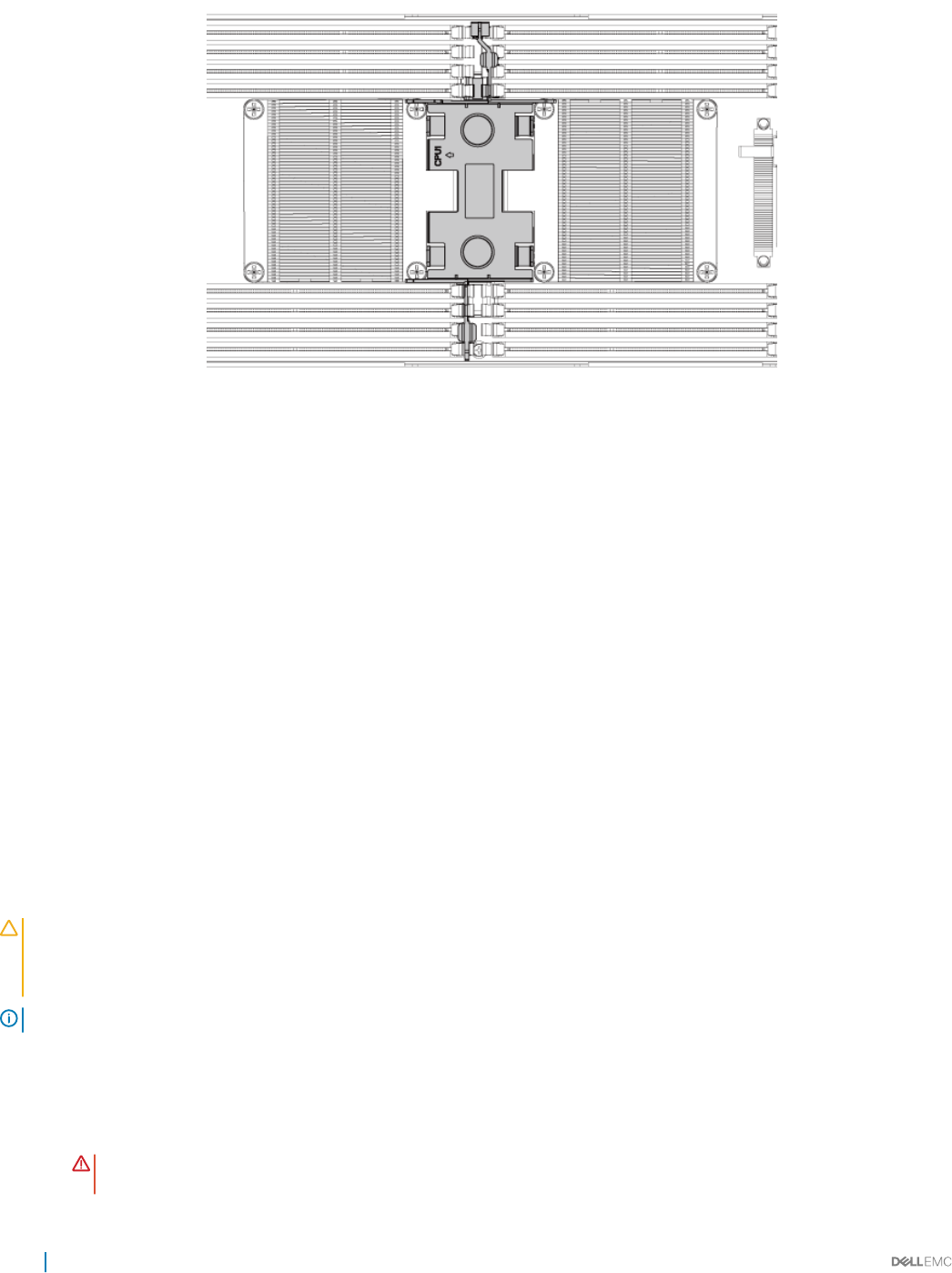
Figure 40. The top view of the installed cooling shroud
Next steps
1 Install the system board assembly.
2 Reconnect the peripherals and connect the system to the electrical outlet.
3 Turn on the system, including any attached peripherals.
Related links
Safety instructions
Installing the system board assembly
Heat sinks
The heat sink transfers heat away form the processor as the processor is unable to dissipate sucient heat to moderate this temperature.
The heat sink is designed to maximize its surface area in contact with the cooling medium surrounding it, such as the air. Thermal grease
improve the heat sink's performance by lling air gaps between the heat sink and the heat spreader on the processor.
Removing the heat sink
Prerequisites
CAUTION: Many repairs may only be done by a certied service technician. You should only perform troubleshooting and simple
repairs as authorized in your product documentation, or as directed by the online or telephone service and support team. Damage
due to servicing that is not authorized by Dell is not covered by your warranty. Read and follow the safety instructions that are
shipped with your product.
NOTE: Place the foolproof pins of two processor heat sinks facing inside.
1 Follow the safety guidelines listed in the Safety instructions section.
2 Turn o the system, including any attached peripherals.
3 Disconnect the system from the electrical outlet and disconnect the peripherals.
4 Remove the system board assembly.
WARNING: The heat sink may be hot to touch for some time after the system has been powered down. Allow the heat
sink to cool before removing it.
84 Installing and removing system components
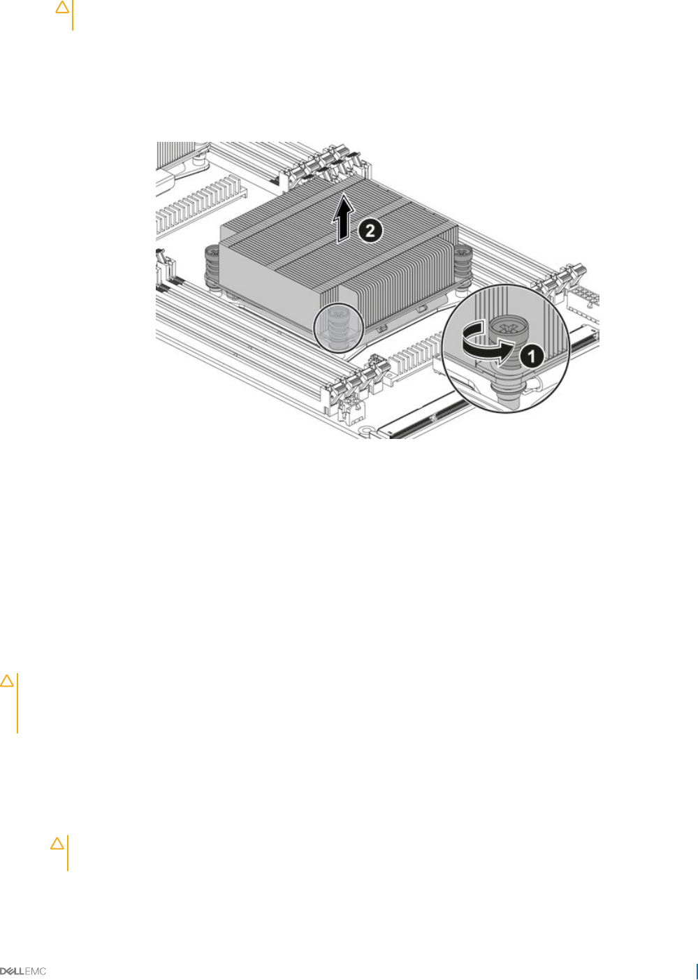
CAUTION: Never remove the heat sink from a processor unless you intend to remove the processor. The heat sink is
necessary to maintain proper thermal conditions.
Steps
1 Using a Phillips screwdriver, loosen one of the heat sink retention screws.
Wait for 30 seconds for the heat sink to loosen from the processor.
2 Remove the other heat sink retention screws.
3 Lift the heat sink o the processor and set the heat sink aside with thermal grease side facing up.
Figure 41. Removing and installing the heat sink
1screw (4) 2 heat sink
Related links
Safety instructions
Removing the system board assembly
Installing the heat sink
Prerequisites
CAUTION: Many repairs may only be done by a certied service technician. You should only perform troubleshooting and simple
repairs as authorized in your product documentation, or as directed by the online or telephone service and support team. Damage
due to servicing that is not authorized by Dell is not covered by your warranty. Read and follow the safety instructions that are
shipped with your product.
Follow the safety guidelines listed in the Safety instructions section.
Steps
1 Using a clean lint-free cloth, remove the thermal grease from the heat sink.
2 Apply new thermal grease evenly to the center of the top of the new processor.
CAUTION: Using excess thermal grease can cause grease to contact the processor shield, which can cause
contamination of the processor socket.
3 Place the heat sink on the processor.
4 Using a Phillips screwdriver, tighten the heat sink retention screws.
Installing and removing system components 85

Next steps
Replace the system board assembly.
Related links
Safety instructions
Installing the system board assembly
Processors
The processor contains memory, peripheral interfaces, and other components of the system. It may have multiple cores. The system may
have multiple processors present. The C6320 system board supports the E5-2600 v3 and E5-2600 v4 processor series.
Removing a processor
Prerequisites
CAUTION: Many repairs may only be done by a certied service technician. You should only perform troubleshooting and simple
repairs as authorized in your product documentation, or as directed by the online or telephone service and support team. Damage
due to servicing that is not authorized by Dell is not covered by your warranty. Read and follow the safety instructions that are
shipped with your product.
1 Follow the safety guidelines listed in the Safety instructions section.
2 Remove the system board assembly.
3 Remove the heat sink.
CAUTION: The processor is held in its socket under strong pressure. The release lever can spring up suddenly if not
rmly grasped.
Steps
1 Position your thumbs rmly over the processor socket release levers and release the levers from the locked position. Rotate the levers
90 degrees upward until the processor is released from the socket.
2 Rotate the processor shield upward and out of the way.
3 Lift the processor out of the socket and leave the socket release levers up so that the socket is ready for the new processor.
CAUTION: Be careful not to bend any of the pins on the CPU socket when removing the processor. Bending the pins
can permanently damage the system board. Be sure to properly align the process or notch to the socket and insert
straight down. Do not move from side to side.
86 Installing and removing system components
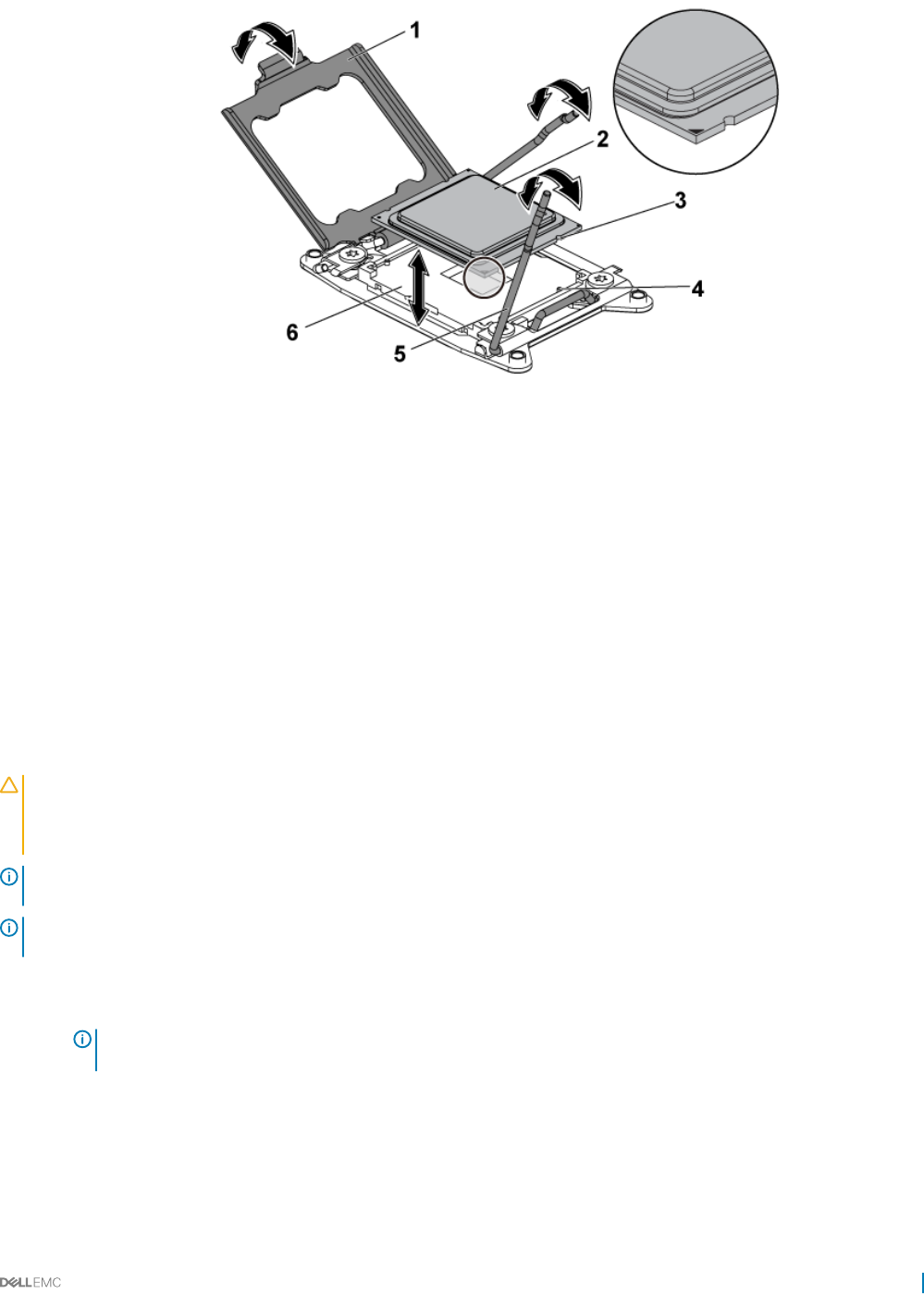
Figure 42. Removing and installing a processor
1 processor shield 2 processor
3 notch in processor (4) 4 socket key (4)
5 socket release lever (2) 6 CPU socket
Related links
Safety instructions
Removing the system board assembly
Removing the heat sink
Installing a processor
Prerequisites
CAUTION: Many repairs may only be done by a certied service technician. You should only perform troubleshooting and simple
repairs as authorized in your product documentation, or as directed by the online or telephone service and support team. Damage
due to servicing that is not authorized by Dell is not covered by your warranty. Read and follow the safety instructions that are
shipped with your product.
NOTE: When installing only one processor, the processor must be installed in the processor 0 (for the socket location, see the
System board connectors section).
NOTE: If you are upgrading your processors, prior to upgrading your system, download and install the latest system BIOS version
from Dell.com/support/home. Follow the instructions included in the le download to install the update on your system.
1Follow the safety guidelines listed in the Safety instructions section.
2 Unpack the processor if it has not been used previously.
NOTE: If the processor has already been used, remove any thermal grease from the top of the processor by using a
lint-free cloth.
3 Remove the system board assembly.
Steps
1 Align the processor with the socket keys on the CPU socket.
Installing and removing system components 87

CAUTION: Positioning the processor incorrectly can permanently damage the system board or the processor. Be careful
not to bend the pins in the CPU socket.
2 With the release lever on the processor socket in the open position, align the processor with the socket keys and set the processor
lightly in the socket.
CAUTION: Do not use force to seat the processor. When the processor is positioned correctly, it engages easily into the
socket.
3 Close the processor shield.
4 Rotate the socket release lever down until it snaps into place.
5 Using a clean lint-free cloth, remove the thermal grease from the heat sink.
6 Apply thermal grease evenly to the center of the top of the new processor.
CAUTION: Using excess thermal grease can cause grease to contact the processor shield, which can cause
contamination of the processor socket.
7 Place the heat sink on the processor.
8 Using a Phillips screwdriver, tighten the heat sink retention screws.
Next steps
1 Replace the system board assembly.
2 Reconnect the system to its electrical outlet and turn on the system, including any attached peripheral devices.
3 Press F2 to enter the System Setup program, and check that the processor information matches the new system conguration. See
the System setup options at boot section.
Related links
Safety instructions
Removing the system board assembly
Installing the heat sink
Installing the system board assembly
System Setup
C6320 system board connectors
Expansion card assembly and expansion card
The expansion card in computer is a printed circuit board that can be inserted into an expansion slot on the computer system board riser
card to add functionality to the computer system through the expansion bus.
NOTE: A missing or an unsupported expansion card riser logs an SEL event. It does not prevent your system from powering on
and no BIOS POST message or F1/F2 pause is displayed.
Removing the expansion card
Prerequisites
CAUTION: Many repairs may only be done by a certied service technician. You should only perform troubleshooting and simple
repairs as authorized in your product documentation, or as directed by the online or telephone service and support team. Damage
due to servicing that is not authorized by Dell is not covered by your warranty. Read and follow the safety instructions that are
shipped with your product.
1 Follow the safety guidelines listed in the Safety instructions section.
2 Turn o the system, including any attached peripherals.
3 Disconnect the system from the electrical outlet and disconnect the peripherals.
4 Remove the system board assembly.
88 Installing and removing system components
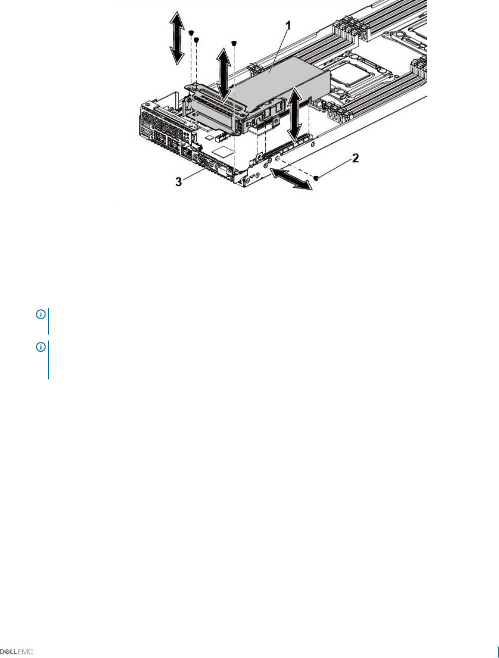
Steps
1 Remove the screws that secure the expansion card assembly.
2 Lift the expansion card assembly out of the system board assembly.
Figure 43. Removing the expansion card assembly
1expansion card assembly 2 screw (4)
3 system board assembly
3 Remove the screw that secures the expansion card.
4 Hold the expansion card by its edges, and carefully remove it from the riser card.
NOTE: If you are removing the card permanently, install an expansion card slot cover over the empty expansion slot
opening, and close the expansion card latch.
NOTE: You must install a ller bracket over an empty expansion slot to maintain Federal Communications Commission
(FCC) certication of the system. The brackets also keep dust and dirt out of the system and aid in proper cooling and
airow inside the system.
Installing and removing system components 89
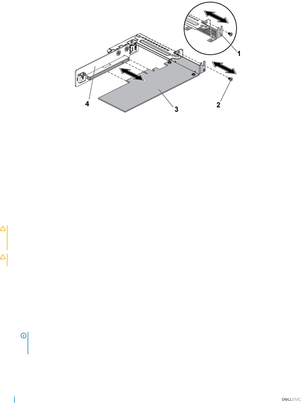
Figure 44. Removing the expansion card
1 expansion card slot cover 2 screw
3 expansion card 4 riser card
Related links
Safety instructions
Removing the system board assembly
Installing the expansion card
Prerequisites
CAUTION: Many repairs may only be done by a certied service technician. You should only perform troubleshooting and simple
repairs as authorized in your product documentation, or as directed by the online or telephone service and support team. Damage
due to servicing that is not authorized by Dell is not covered by your warranty. Read and follow the safety instructions that are
shipped with your product.
CAUTION: Expansion cards can only be installed in the slots on the expansion card riser. Do not attempt to install expansion
cards directly into the riser connector on the system board.
1 Follow the safety guidelines listed in the Safety instructions section.
2 Unpack the expansion card and prepare it for installation. For instructions, see the documentation accompanying the card.
Steps
1 Remove the screws that secure the expansion card assembly.
2 Lift the expansion card assembly away from the system board assembly.
3 Remove the screw that secures the ller bracket.
4 Hold the ller bracket by its edges, and carefully remove it from the riser card.
NOTE: Retain this bracket in case you need to remove the expansion card. Filler brackets must be installed over empty
expansion cards slots to maintain FCC certication of the system. The brackets also keep dust and dirt out of the
system and aid in proper cooling and airow inside the system.
5 Holding the card by its edges, position the card so that the card edge connector aligns with the riser card on the riser card.
6 Insert the card edge connector rmly into the riser card until the card is fully seated.
7 Replace the screw that secures the expansion card.
90 Installing and removing system components

8 Place the expansion card assembly into the system board assembly.
9 Install the screws that secure the expansion card assembly.
Next steps
1 Install the system board assembly.
2 Reconnect the peripherals and connect the system to the electrical outlet.
3 Turn on the system, including any attached peripherals.
Related links
Safety instructions
Removing the system board assembly
Installing the system board assembly
PCI-E slot priority
There is no slot priority for PowerEdge C6320 as the C6320 system board has only one PCI-E Gen 3 x8 mezzanine card slot.
For the system with 1U C6320 system board assembly, only one PCI-E card can be installed in the PCI-E Gen3 x16 slot 1.
PERC cards
Dell PowerEdge C6320 supports H330 and 12 Gbps SAS HBA cards. Dell PowerEdge C6320 also supports H730 with processor under 105
W for thermal restrictions.
Removing the PERC card
Prerequisites
CAUTION: Many repairs may only be done by a certied service technician. You should only perform troubleshooting and simple
repairs as authorized in your product documentation, or as directed by the online or telephone service and support team. Damage
due to servicing that is not authorized by Dell is not covered by your warranty. Read and follow the safety instructions that are
shipped with your product.
1 Follow the safety guidelines listed in the Safety instructions section.
2 Follow the procedure listed in the Before working inside your system section.
Steps
1 Locate the PERC card on the system board.
2 To disconnect the storage controller cable:
a Remove the screws that secure the cable to the card.
b Hold the cable on both sides of the cable connector, and pull the cable away from the PERC card.
3 Angle the card so that the other end of the card disengages from the storage-controller card holder on the system board.
Related links
Safety instructions
Before working inside your system
Installing the PERC card
Installing and removing system components 91
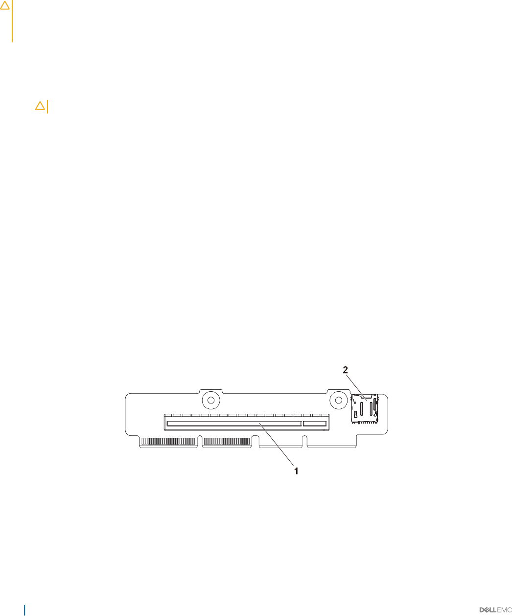
Installing the PERC card
Prerequisites
CAUTION: Many repairs may only be done by a certied service technician. You should only perform troubleshooting and simple
repairs as authorized in your product documentation, or as directed by the online or telephone service and support team. Damage
due to servicing that is not authorized by Dell is not covered by your warranty. Read and follow the safety instructions that are
shipped with your product.
Follow the safety guidelines listed in the Safety instructions section.
Steps
1 Locate the PERC card connector on the system board and align one end of the card with the card holder on the system board.
CAUTION: To prevent damage to the card, you must hold the card by its edges only.
2 Lower the other end of the card into the card holder on the system board.
3 Connect the storage controller cable:
a Hold the cable on both sides of the cable connector, and connect to the PERC card.
b Attach the crews to secure the cable to the card.
4 Connect the SAS data cable connector to the card.
5 Route the SAS data cable through the clip on the card and through the channel on the inner side of the chassis.
6 Attach the connector labeled "SAS A" to connector SAS A on the backplane, and attach the connector labeled "SAS B" to connector
SAS B on the backplane.
Next steps
Follow the procedure listed in the After working inside your system section.
Riser card
Optional riser cards
Figure 45. 1U riser card for 1U node
1PCI-E Gen 3 x16 2 microSD card socket
92 Installing and removing system components
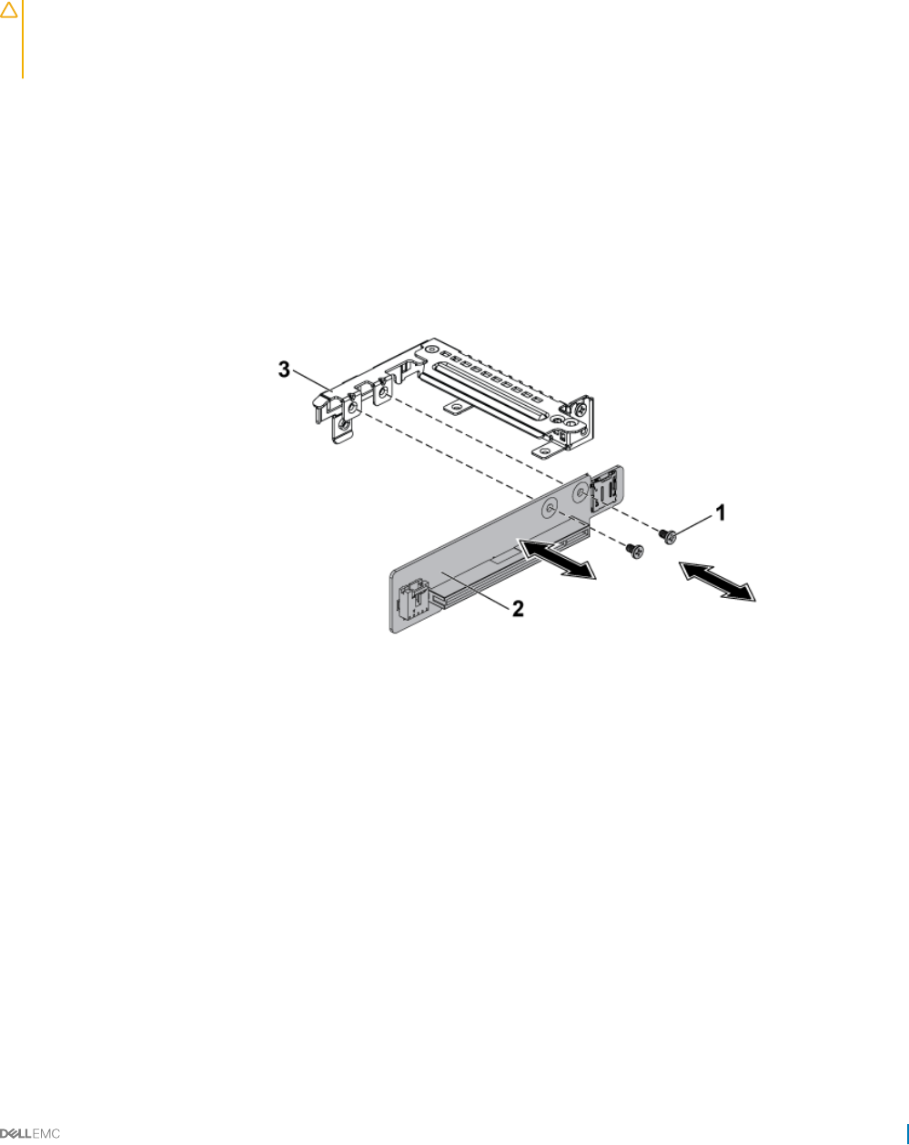
Removing the riser card
Prerequisites
CAUTION: Many repairs may only be done by a certied service technician. You should only perform troubleshooting and simple
repairs as authorized in your product documentation, or as directed by the online or telephone service and support team. Damage
due to servicing that is not authorized by Dell is not covered by your warranty. Read and follow the safety instructions that are
shipped with your product.
1 Follow the safety guidelines listed in the Safety instructions section.
2 Turn o the system, including any attached peripherals.
3 Disconnect the system from the electrical outlet and disconnect the peripherals.
4 Remove the system board assembly.
5 Remove the expansion card.
Steps
1 Remove the screws that secure the riser card to the expansion card bracket.
2 Pull the riser card away from the expansion card bracket.
Figure 46. Removing and installing the riser card
1screw (2) 2 riser card
3 expansion card bracket
Related links
Safety instructions
Removing the system board assembly
Removing the expansion card
Installing and removing system components 93

Installing the riser card
Prerequisites
CAUTION: Many repairs may only be done by a certied service technician. You should only perform troubleshooting and simple
repairs as authorized in your product documentation, or as directed by the online or telephone service and support team. Damage
due to servicing that is not authorized by Dell is not covered by your warranty. Read and follow the safety instructions that are
shipped with your product.
Follow the safety guidelines listed in the Safety instructions section.
Steps
1 Place the riser card into the expansion card bracket.
2 Replace the screws that secure the riser card to the expansion card bracket.
Next steps
1 Install the expansion card.
2 Install the system board assembly.
3 Reconnect the peripherals and connect the system to the electrical outlet.
4 Turn on the system, including any attached peripherals.
Related links
Safety instructions
Installing the expansion card
Installing the system board assembly
Optional mezzanine cards
The optional Mezzanine cards supported on C6320 are:
Table 28. Supported mezzanine cards
Type Card
HBA/RAID LSI 2008 mezzanine
Dual Port 1GbE Powerville
Dual Port 10GbE Twinville
Single port FDR ConnectX3 VPI
Dual Port QSFP+ ConnectX3 VPI
Dual Port SFP+ ConnectX3-Pro
Dual Port 10GE Intel 82599 mezzanine
Dual Port QSFP+ ConnectX4 VPI
Single Port QSFP+ ConnectX4 VPI
Dual Port SFP ConnectX4 LX
94 Installing and removing system components
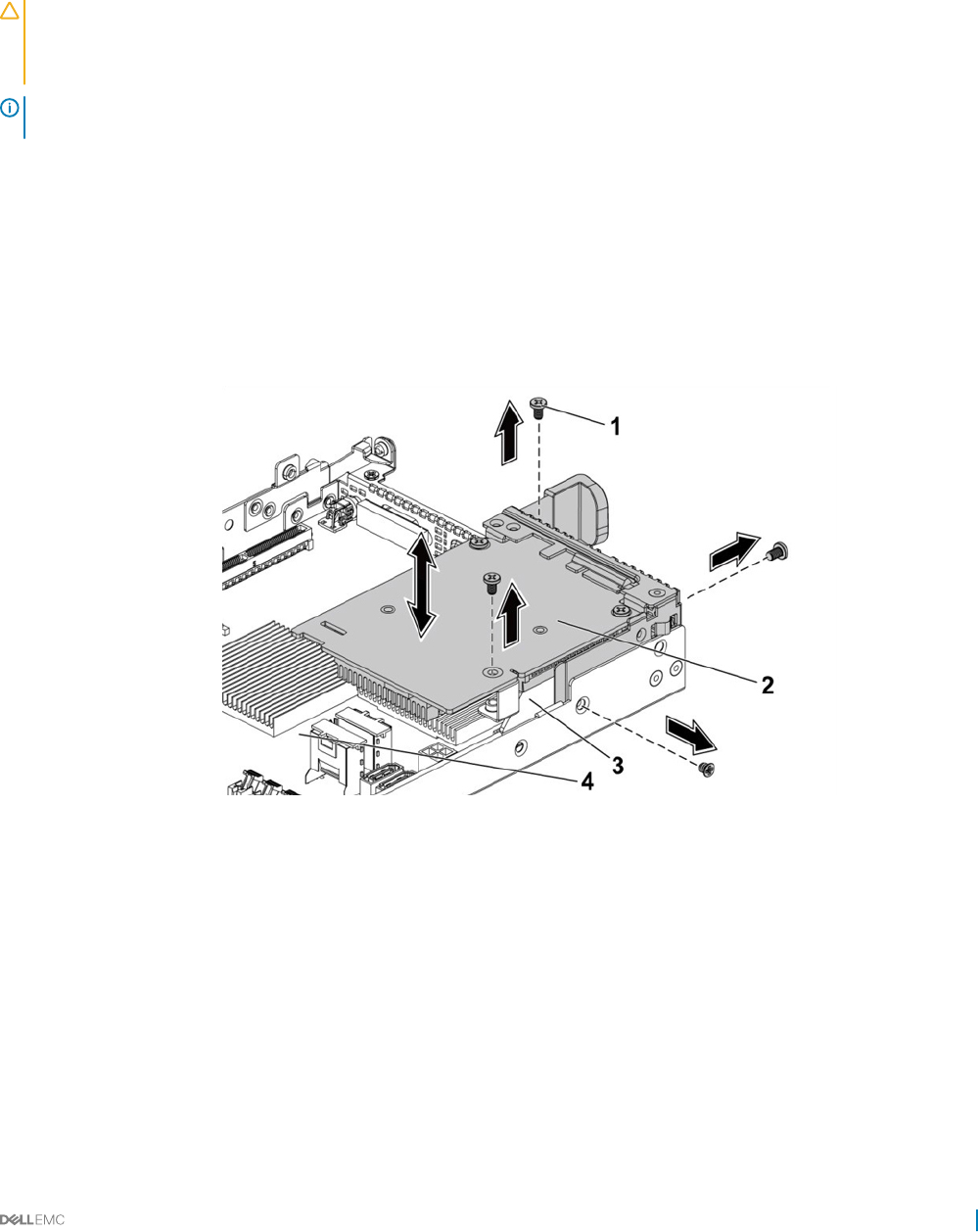
Removing the optional LSI 2008 SAS mezzanine card
Prerequisites
CAUTION: Many repairs may only be done by a certied service technician. You should only perform troubleshooting and simple
repairs as authorized in your product documentation, or as directed by the online or telephone service and support team. Damage
due to servicing that is not authorized by Dell is not covered by your warranty. Read and follow the safety instructions that are
shipped with your product.
NOTE: The LSI 2008 SAS mezzanine card is seated in PCI-E Gen3 x8 mezzanine slot 3 on the system board, which is not active
in 1-processor conguration. See the C6320 system board connectors section.
1 Follow the safety guidelines listed in the Safety instructions section.
2 Turn o the system, including any attached peripherals.
3 Disconnect the system from the electrical outlet and disconnect the peripherals.
4 Remove the system board assembly.
Steps
1 Disconnect all the cables from the mezzanine card.
2 Remove the screws that secure the LSI 2008 SAS mezzanine card.
3 Lift the mezzanine card out of the system-board assembly.
Figure 47. Removing and installing the LSI 2008 SAS mezzanine card
1screw (3) 2 LSI 2008 SAS mezzanine card
3 card bridge card 4 system board assembly
Related links
Safety instructions
C6320 system board connectors
Installing and removing system components 95
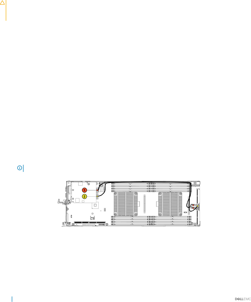
Installing the optional LSI 2008 SAS mezzanine card
Prerequisites
CAUTION: Many repairs may only be done by a certied service technician. You should only perform troubleshooting and simple
repairs as authorized in your product documentation, or as directed by the online or telephone service and support team. Damage
due to servicing that is not authorized by Dell is not covered by your warranty. Read and follow the safety instructions that are
shipped with your product.
Follow the safety guidelines listed in the Safety instructions section.
Steps
1 Place the LSI 2008 SAS mezzanine card on the system board assembly.
2 Install the screws that secure the LSI 2008 SAS mezzanine card.
3 Reconnect all the cables to the LSI 2008 SAS mezzanine card.
Next steps
1 Install the system board assembly.
2 Reconnect the peripherals and connect the system to the electrical outlet.
3 Turn on the system, including any attached peripherals.
Related links
Safety instructions
Installing the system board assembly
Cable routing for LSI 2008 SAS mezzanine card
1 Connect the mini-SAS/SGPIO cable to the LSI 2008 SAS Mezzanine card, and connect the other end of the cable to the
corresponding connectors on the system board.
2 Connect the mini-SAS cable to the LSI 2008 SAS Mezzanine card, and connect the other end of the cable to the corresponding
connector on the system board.
NOTE: The SGPIO cable must be connected before the LSI 2008 SAS Mezzanine card is installed.
Figure 48. Cable routing for LSI 2008 SAS mezzanine card
96 Installing and removing system components
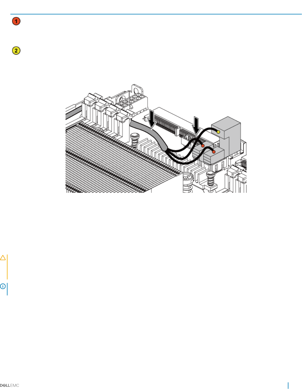
Table 29. Cable routing for LSI 2008 SAS mezzanine card
Item Cable From (LSI 2008 SAS
mezzanine card)
To (system board)
Mini-SAS/SGPIO cable Mini-SAS connector 4-7 (J4) SAS/SATA input connector 4
and SAS/SATA input connector
5
Mini-SAS cable Mini-SAS connector 0-3 (J3) Mini SAS HD connector 0-3
3 Press down on the cables, and ensure the cables are routed lower than the height of the CPU heat sinks.
Figure 49. Cable routing down for LSI 2008 SAS mezzanine card (1U node)
Removing the 1GbE mezzanine card
Prerequisites
CAUTION: Many repairs may only be done by a certied service technician. You should only perform troubleshooting and simple
repairs as authorized in your product documentation, or as directed by the online or telephone service and support team. Damage
due to servicing that is not authorized by Dell is not covered by your warranty. Read and follow the safety instructions that are
shipped with your product.
NOTE: The 1GbE mezzanine card is seated in PCI-E Gen3 x8 mezzanine slot 3 on the system board, which is not active in a one
processor conguration. See the C6320 system board connectors section.
1Follow the safety guidelines listed in the Safety instructions section.
2 Turn o the system, including any attached peripherals.
3 Disconnect the system from the electrical outlet and disconnect the peripherals.
4 Remove the system board assembly.
5 Disconnect all the cables from the 1GbE mezzanine card.
Steps
1 Remove the screws that secure the expansion card bracket.
2 Lift the expansion card bracket out of the system board assembly.
Installing and removing system components 97
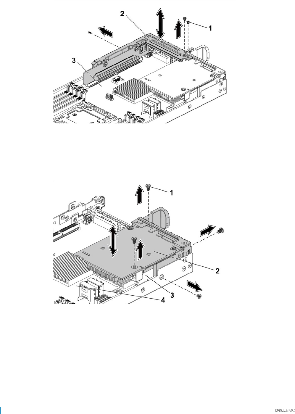
Figure 50. Removing and installing the expansion card bracket
1 screw (3) 2 expansion card bracket
3 system board assembly
3 Remove the screws that secure the 1GbE mezzanine card assembly.
4 Lift the 1GbE mezzanine card assembly away from the card bridge board on the system board.
Figure 51. Removing and installing the 1GbE mezzanine card assembly
1screw (4) 2 1GbE mezzanine card assembly
3 mezzanine card bridge board 4 system board assembly
5 Remove the screws that secure the 1GbE mezzanine card to the bracket.
6 Remove the 1GbE mezzanine card from the bracket.
98 Installing and removing system components
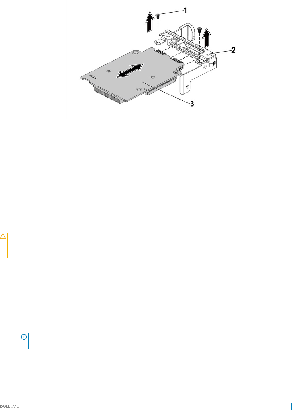
Figure 52. Removing and installing the 1GbE mezzanine card
1 screw (2) 2 mezzanine card bracket
3 1GbE mezzanine card
Related links
Safety instructions
C6320 system board connectors
Removing the system board assembly
Installing the 1GbE mezzanine card
Prerequisites
CAUTION: Many repairs may only be done by a certied service technician. You should only perform troubleshooting and simple
repairs as authorized in your product documentation, or as directed by the online or telephone service and support team. Damage
due to servicing that is not authorized by Dell is not covered by your warranty. Read and follow the safety instructions that are
shipped with your product.
Follow the safety guidelines listed in the Safety instructions section.
Steps
1 Attach the 1GbE mezzanine card to the bracket by aligning the four ports to the corresponding port slots on the bracket.
2 Install the screws to secure the 1GbE mezzanine card to the bracket.
3 Install the 1GbE mezzanine card assembly to the card bridge board on the system board assembly.
4 Install the screws to secure the 1GbE mezzanine card assembly to the system board assembly.
5 Place the expansion card bracket into the system board assembly.
6 Replace the screws that secure the expansion card bracket.
NOTE: For more information about setting VLAN in VMware for 1GbE mezzanine card, see VMware* vSphere ESX 5.x
iSCSI Boot Support with VLANs.
Next steps
1 Reconnect all the cables to the 1GbE mezzanine card.
2 Replace the system board assembly.
3 Reconnect the peripherals and connect the system to the electrical outlet.
Installing and removing system components 99
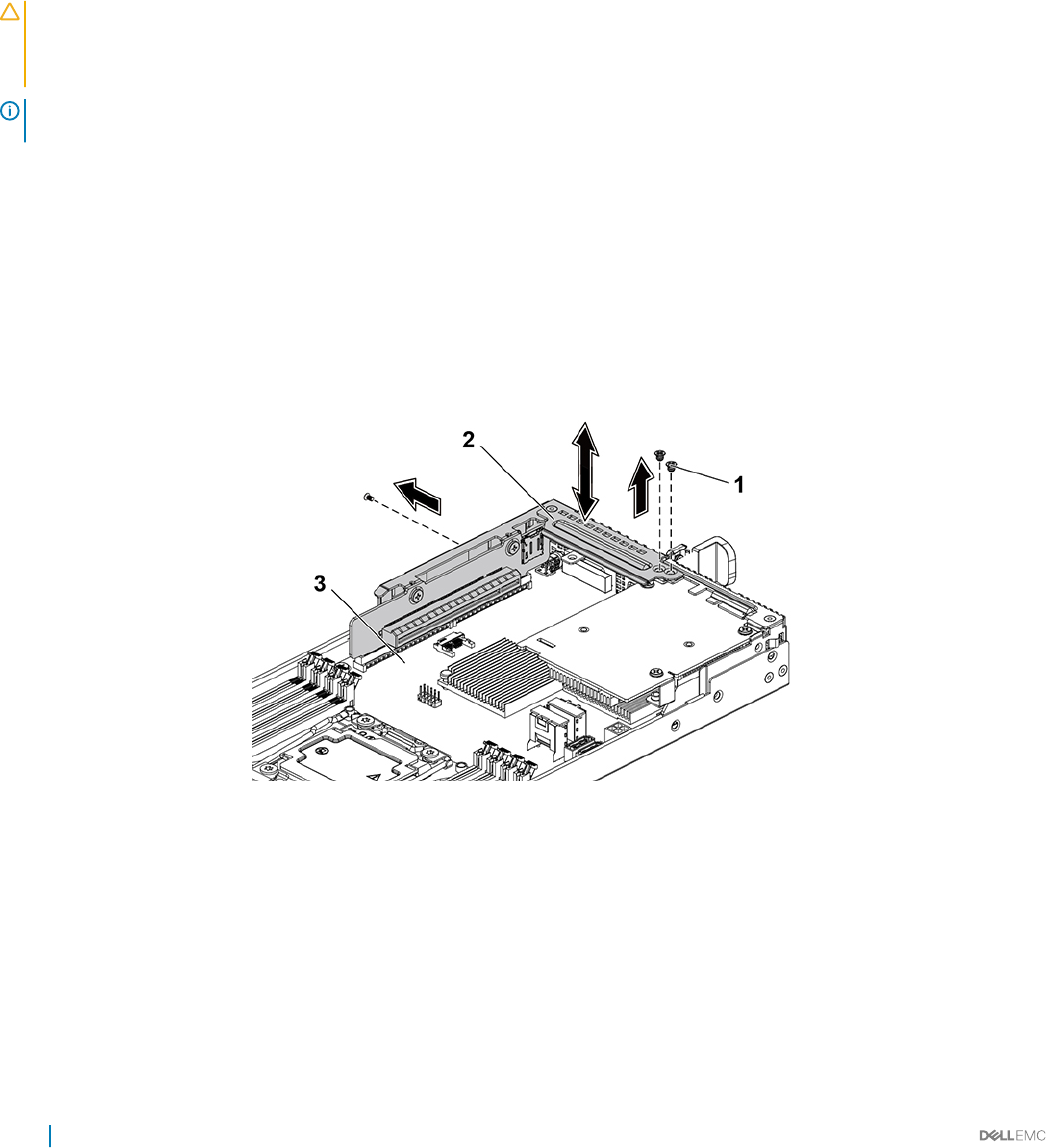
4 Turn on the system, including any attached peripherals.
Related links
Safety instructions
Installing the system board assembly
Removing the 10GbE mezzanine card
Prerequisites
CAUTION: Many repairs may only be done by a certied service technician. You should only perform troubleshooting and simple
repairs as authorized in your product documentation, or as directed by the online or telephone service and support team. Damage
due to servicing that is not authorized by Dell is not covered by your warranty. Read and follow the safety instructions that are
shipped with your product.
NOTE: The 10GbE mezzanine card is seated in PCI-E Gen3 x8 mezzanine slot 3 on the system board, which is not active in 1-
processor conguration. See the C6320 system board connectors section.
1 Follow the safety guidelines listed in the Safety instructions section.
2 Turn o the system, including any attached peripherals.
3 Disconnect the system from the electrical outlet and disconnect the peripherals.
4 Remove the system board assembly.
Steps
1 Disconnect all the cables from the 10GbE mezzanine card.
2 Remove the screws that secure the expansion card bracket.
3 Lift the expansion card bracket out of the system board assembly.
Figure 53. Removing and installing the expansion card bracket
1screw (3) 2 expansion card bracket
3 system board assembly
4 Remove the screws that secure the 10GbE mezzanine card assembly.
5 Lift the 10GbE mezzanine card assembly away from the card bridge board on the system board.
100 Installing and removing system components
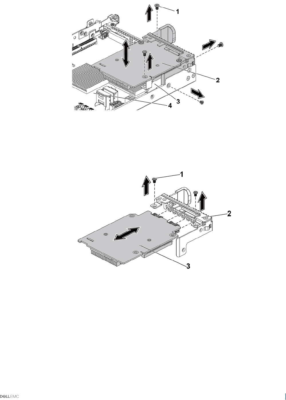
Figure 54. Removing and installing the 10GbE mezzanine card assembly
1 screw (4) 2 10GbE mezzanine card assembly
3 mezzanine card bridge board 4 system board assembly
6 Remove the screws that secure the 10GbE mezzanine card to the bracket.
7 Remove the 10GbE mezzanine card from the bracket.
Figure 55. Removing and installing the 10GbE mezzanine card
1screw (2) 2 mezzanine card bracket
3 10GbE mezzanine card
Related links
Safety instructions
C6320 system board connectors
Removing the system board assembly
Installing and removing system components 101

Installing the 10GbE mezzanine card
Prerequisites
CAUTION: Many repairs may only be done by a certied service technician. You should only perform troubleshooting and simple
repairs as authorized in your product documentation, or as directed by the online or telephone service and support team. Damage
due to servicing that is not authorized by Dell is not covered by your warranty. Read and follow the safety instructions that are
shipped with your product.
Follow the safety guidelines listed in the Safety instructions section.
Steps
1 Attach the 10 GbE mezzanine card to the bracket by aligning the four ports to the corresponding port slots on the bracket.
2 Install the screws to secure the 10GbE mezzanine card to the bracket.
3 Install the 10 GbE mezzanine card assembly to the card bridge board on the system-board assembly.
4 Install the screws to secure the 10 GbE mezzanine card assembly to the syste -board assembly.
5 Place the expansion-card bracket into the system board assembly.
6 Install the screws that secure the expansion card bracket.
NOTE: For more information about setting VLAN in VMware for 10 GbE mezzanine card, see VMware* vSphere ESX 5.x
iSCSI Boot Support with VLANs.
Next steps
1 Reconnect all the cables to the 10 GbE mezzanine card.
2 Install the system board assembly.
3 Reconnect the peripherals and connect the system to the electrical outlet.
4 Turn on the system, including any attached peripherals.
Related links
Safety instructions
Installing the system board assembly
Mezzanine card bridge board
Removing the mezzanine card bridge board
Prerequisites
CAUTION: Many repairs may only be done by a certied service technician. You should only perform troubleshooting and simple
repairs as authorized in your product documentation, or as directed by the online or telephone service and support team. Damage
due to servicing that is not authorized by Dell is not covered by your warranty. Read and follow the safety instructions that are
shipped with your product.
1 Follow the safety guidelines listed in the Safety instructions section.
2 Turn o the system, including any attached peripherals.
3 Disconnect the system from the electrical outlet and disconnect the peripherals.
4 Remove the system board assembly.
5 Remove the mezzanine card.
Steps
Pull the mezzanine card bridge board away from the mezzanine slot on the system board.
102 Installing and removing system components
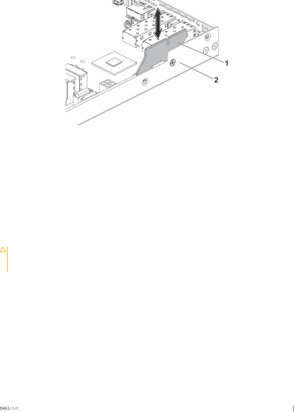
Figure 56. Removing and installing the mezzanine card bridge board
1 system board assembly 2 mezzanine card bridge board
Related links
Safety instructions
Removing the system board assembly
Removing the optional LSI 2008 SAS mezzanine card
Removing the 1GbE mezzanine card
Removing the 10GbE mezzanine card
Installing the mezzanine card bridge board
Prerequisites
CAUTION: Many repairs may only be done by a certied service technician. You should only perform troubleshooting and simple
repairs as authorized in your product documentation, or as directed by the online or telephone service and support team. Damage
due to servicing that is not authorized by Dell is not covered by your warranty. Read and follow the safety instructions that are
shipped with your product.
Follow the safety guidelines listed in the Safety instructions section.
Steps
Install the mezzanine card bridge board into the mezzanine slot on the system board.
Next steps
1 Install the mezzanine card.
2 Install the system board assembly.
3 Reconnect the peripherals and connect the system to the electrical outlet.
4 Turn on the system, including any attached peripherals.
Installing and removing system components 103
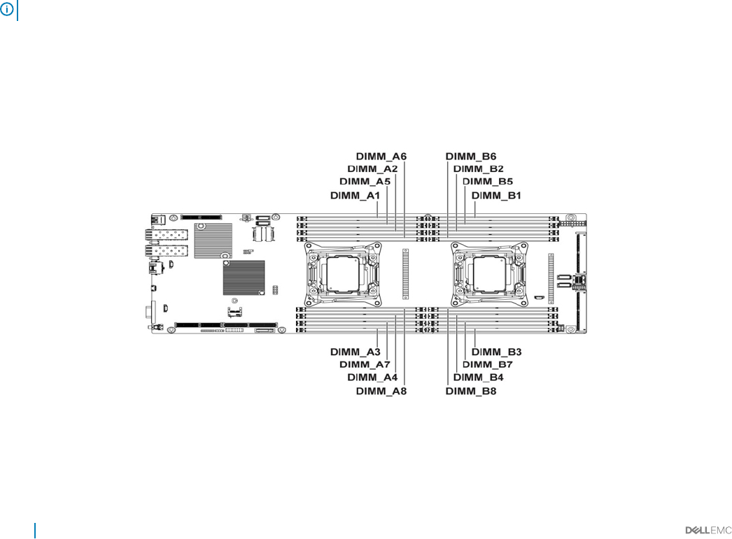
Related links
Safety instructions
Installing the optional LSI 2008 SAS mezzanine card
Installing the 1GbE mezzanine card
Installing the 10GbE mezzanine card
Installing a system board
Installing the system board assembly
System memory
System memory holds the instructions that the processor executes. Each system board has sixteen DDR4 memory module sockets for the
installation of up to sixteen registered DDR4-2400 MHz (2400 MHz at 2 memory modules per channel) memory modules to support
processor 1 and processor 2. For the location of the memory modules, see the C6320 system board connectors section.
Related links
C6320 system board connectors
Memory slot features
• Support 8 channels, 16 DDR4 registered DIMMs (RDIMMs)
• Speed up to 2400 MT/s
• Maximum capacities: 512 GB with 32 GB RDIMM
• Supports DDR4
• Supports Error Correction Code (ECC)
NOTE: Linux operating system does not support the S4 (hibernation) mode.
Supported memory module conguration
For the sequence of the 16 memory-module sockets, the system requires at least one memory module installed on processor 1’s DIMM slot
1 in order to boot up. When you insert the memory modules, always start with CHA_A1. The optimized memory module installation
sequence is 1, 2, 3, 4, 5, 6, 7, and 8.
Figure 57. DIMM slot locations
104 Installing and removing system components

Table 30. Memory module congurations for single processor
Processor 1
Memory
modules
CHA CHB CHC CHD
A1 A5 A2 A6 A3 A7 A4 A8
1 √ ‒ ‒ ‒ ‒ ‒ ‒ ‒
2 √ ‒√‒‒‒‒‒
3 √ ‒√‒√‒‒‒
4 √ ‒√‒√‒√‒
6 √ √ √ √ √ ‒√‒
8 √ √ √ √ √ √ √ √
Table 31. Memory module congurations for dual processors
Processor 1
Memory
modules
CHA CHB CHC CHD
A1 A5 A2 A6 A3 A7 A4 A8
2 √ ‒ ‒ ‒ ‒ ‒ ‒ ‒
6 √ ‒√‒√‒‒‒
8 √ ‒√‒√‒√‒
12 √ √ √ √ √ ‒√‒
16 √ √ √ √ √ √ √ √
Table 32. Memory module congurations for dual processors
Processor 2
Memory
modules
CHA CHB CHC CHD
B1 B5 B2 B6 B3 B7 B4 B8
2 √ ‒ ‒ ‒ ‒ ‒ ‒ ‒
6 √ ‒√‒√‒‒‒
8 √ ‒√‒√‒√‒
12 √ √ √ √ √ ‒√‒
16 √ √ √ √ √ √ √ √
Installing and removing system components 105
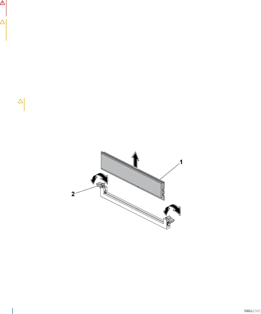
Removing the memory modules
Prerequisites
WARNING: The memory modules are hot to the touch for some time after the system has been powered down. Allow time for
the memory modules to cool before handling them. Handle the memory modules by the card edges and avoid touching the
components on the memory module.
CAUTION: Many repairs may only be done by a certied service technician. You should only perform troubleshooting and simple
repairs as authorized in your product documentation, or as directed by the online or telephone service and support team. Damage
due to servicing that is not authorized by Dell is not covered by your warranty. Read and follow the safety instructions that are
shipped with your product.
1 Follow the safety guidelines listed in the Safety instructions section.
2 Turn o the system, including any attached peripherals.
3 Disconnect the system from the electrical outlet and disconnect the peripherals.
4 Remove the system board assembly.
5 Remove the cooling shroud.
Steps
1 Locate the memory module sockets.
CAUTION: Handle each memory module only on either card edge, ensuring not to touch the middle of the memory
module. To avoid damaging components on the memory module, remove only one memory module at a time.
2 Simultaneously press down and out on the ejectors at both ends of the memory module socket until the memory module is released
from the socket.
3 Lift the memory module out of the socket by holding the memory module only by its edges.
Figure 58. Removing a memory module
1memory module 2 memory module socket ejector (2)
Related links
Safety instructions
Removing the system board assembly
Removing the cooling shroud
106 Installing and removing system components
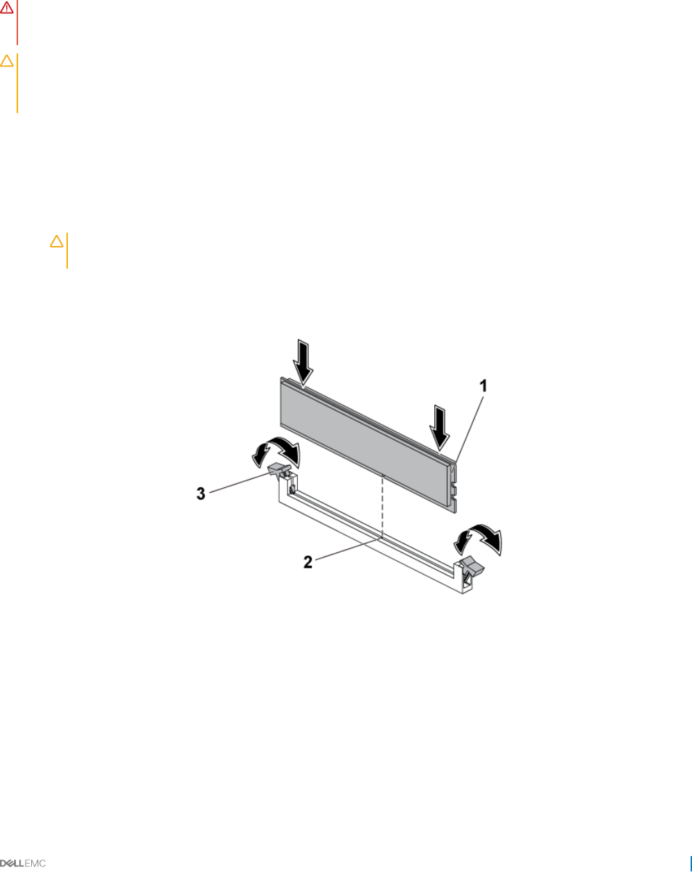
Installing the memory modules
Prerequisites
WARNING: The memory modules are hot to the touch for some time after the system has been powered down. Allow time for
the memory modules to cool before handling them. Handle the memory modules by the card edges and avoid touching the
components on the memory module.
CAUTION: Many repairs may only be done by a certied service technician. You should only perform troubleshooting and simple
repairs as authorized in your product documentation, or as directed by the online or telephone service and support team. Damage
due to servicing that is not authorized by Dell is not covered by your warranty. Read and follow the safety instructions that are
shipped with your product.
Follow the safety guidelines listed in the Safety instructions section.
Steps
1 Press down and out on the ejectors on each end of the memory module socket.
2 Align the memory module correctly with the alignment key of the memory module socket.
3 Press down rmly on the memory module with your thumbs until the module snaps into place.
CAUTION: Even pressure during insertion must be applied at both ends of the module simultaneously to prevent
damage to the socket. No pressure should be applied to the center of the module.
4 Complete the latching of the module into the socket by applying inward pressure to the socket ejectors to ensure that the ejectors are
in a locked position. When the memory module is properly seated in the socket, the ejectors on the memory module socket align with
the ejectors on other identical sockets that have memory modules installed.
Figure 59. Installing a memory module
1memory module 2 alignment key
3 memory module socket ejector (2)
Next steps
1 Install the cooling shroud.
2 Install the system board assembly.
3 Press F2 to enter System Setup, and check the System Memory setting.
4 If the value is incorrect, one or more of the memory modules may not be installed properly. Ensure that the memory modules are rmly
seated in the sockets.
Installing and removing system components 107

5 Run the system memory test in the system diagnostics.
Related links
Safety instructions
Installing the cooling shroud
Installing the system board assembly
System battery
The system battery is used for low-level system functions like powering the real-time clock and storing the computer’s BIOS settings.
Replacing the system battery
Prerequisites
WARNING: There is a danger of a new battery exploding if it is incorrectly installed. Replace the battery only with the same or
equivalent type recommended by the manufacturer. See your safety information for additional information.
CAUTION: Many repairs may only be done by a certied service technician. You should only perform troubleshooting and simple
repairs as authorized in your product documentation, or as directed by the online or telephone service and support team. Damage
due to servicing that is not authorized by Dell is not covered by your warranty. Read and follow the safety instructions that are
shipped with your product.
1 Follow the safety guidelines listed in the Safety instructions section.
2 Turn o the system, including any attached peripherals.
3 Disconnect the system from the electrical outlet and peripherals.
4 Remove the system board assembly.
5 Remove the cooling shroud.
6 Remove the expansion card assembly.
Steps
1 Push the battery latch and lift the battery out of the connector.
CAUTION: To avoid damage to the battery connector, you must rmly support the connector while installing or
removing a battery.
2 Hold the new battery with the "+" facing the positive side of battery connector.
3 Insert the battery into the battery holder until it is seated in place.
108 Installing and removing system components
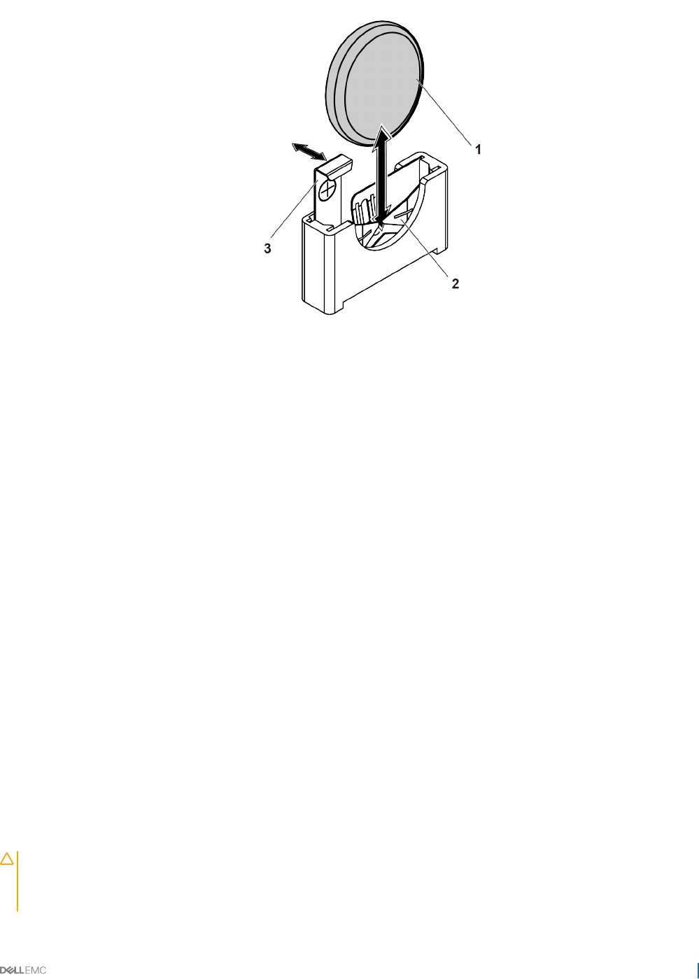
Figure 60. Replacing the system battery
1 system battery 2 negative side of battery connector
3 battery latch
Next steps
1 Replace the system board assembly.
2 Reconnect the system to the electrical outlet.
3 Turn on the system, including any attached peripherals.
4 Enter System Setup to conrm that the battery is operating properly. See the System setup section.
5 In System Setup, enter correct time and date in the Time and Date elds.
6 Exit System Setup.
Related links
Safety instructions
Removing the system board assembly
Removing the cooling shroud
Removing the expansion card
Installing the system board assembly
System Setup
System board
Removing a system board
Prerequisites
CAUTION: Many repairs may only be done by a certied service technician. You should only perform troubleshooting and simple
repairs as authorized in your product documentation, or as directed by the online or telephone service and support team. Damage
due to servicing that is not authorized by Dell is not covered by your warranty. Read and follow the safety instructions that are
shipped with your product.
Installing and removing system components 109
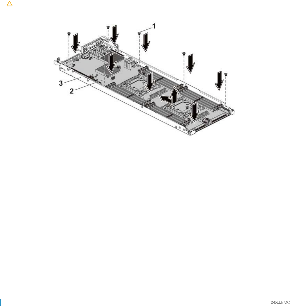
1 Follow the safety guidelines listed in the Safety instructions section.
2 Turn o the system, including any attached peripherals.
3 Disconnect the system from the electrical outlet and disconnect the peripherals.
4 Remove the system board assembly.
5 Remove the cooling shroud.
6 Remove the expansion card assembly.
7 Remove the heat sinks.
8 Remove the memory modules.
9 If installed, remove the SAS mezzanine card, 1 GbE mezzanine card, or 10 GbE mezzanine card.
10 Disconnect all the cables from the system board.
Steps
1 Remove the screws that secure the system board to the system board assembly and then slide the system board.
CAUTION: Do not lift the system board by holding a memory module, processor, or other components.
2 Hold the system board by the edges and lift the system board away from the system board assembly.
Figure 61. Removing and installing the system board
1screw (8) 2 system board
3 system board assembly
Related links
Safety instructions
Removing the system board assembly
Removing the cooling shroud
Removing the expansion card
Removing the heat sink
Removing the memory modules
Removing the optional LSI 2008 SAS mezzanine card
Removing the 1GbE mezzanine card
Removing the 10GbE mezzanine card
110 Installing and removing system components

Installing a system board
Prerequisites
CAUTION: Many repairs may only be done by a certied service technician. You should only perform troubleshooting and simple
repairs as authorized in your product documentation, or as directed by the online or telephone service and support team. Damage
due to servicing that is not authorized by Dell is not covered by your warranty. Read and follow the safety instructions that are
shipped with your product.
Follow the safety guidelines listed in the Safety instructions section.
Steps
1 Holding the system board by the edges, slide the system board into the system board assembly.
2 Install the screws to secure the system board to the system board assembly.
Next steps
1 Install the Trusted Platform Module (TPM). For information how to install the TPM, see the Installing the Trusted Platform Module
section. For more information on the TPM, see the Trusted Platform Module section.
NOTE: The TPM plug-in module is attached to the system board and cannot be removed. A replacement TPM plug-in
module will be provided for all system board replacements where a TPM plug-in module was installed.
2 Transfer the processors to the new system board.
3 Remove the memory modules and transfer them to the same locations on the new board.
4 Replace the heat sinks.
5 Install the expansion card assembly.
6 If applicable, install the SAS mezzanine card, 1 GbE mezzanine card, or 10 GbE mezzanine card.
7 Connect all the cables to the system board.
8 Install the cooling shroud.
9 Follow the procedure listed in the After working inside your system section.
10 Import your new or existing iDRAC Enterprise license. For more information, see Integrated Dell Remote Access Controller User's
Guide, at Dell.com/esmmanuals.
11 Ensure that you:
a Use the Easy Restore feature to restore the Service Tag. For more information, see the Easy restore section.
b If the Service Tag is not backed up in the backup ash device, enter the system Service Tag manually. For more information, see
the Entering the system Service Tag section.
c Update the BIOS and iDRAC versions.
d Re-enable the Trusted Platform Module (TPM). For more information, see the Re-enabling the Trusted Platform Module (TPM)
section.
Related links
Safety instructions
Removing a processor
Installing a processor
Removing the memory modules
Installing the memory modules
Installing the heat sink
Installing the expansion card
Installing the optional LSI 2008 SAS mezzanine card
Installing the 1GbE mezzanine card
Installing the 10GbE mezzanine card
Installing the cooling shroud
Installing the system board assembly
Installing and removing system components 111
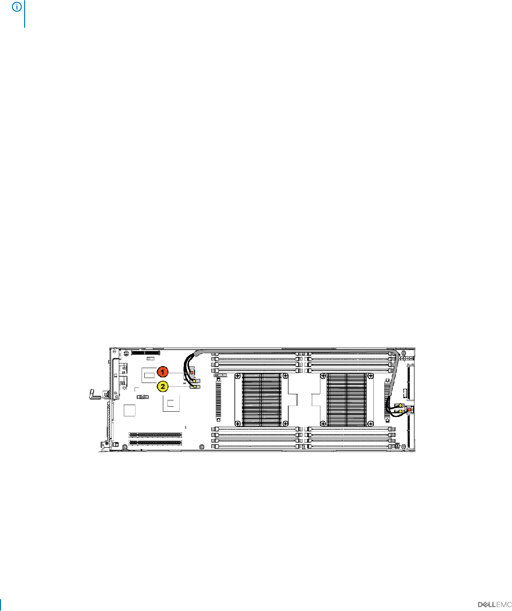
Entering the system Service Tag by using System Setup
1 Turn on the system.
2 Press F2 to enter System Setup.
3 Click Service Tag Settings.
4 Enter the Service Tag.
NOTE: You can enter the Service Tag only when the Service Tag eld is empty. Ensure that you enter the correct
Service Tag. After the Service Tag is entered, it cannot be updated or changed.
5 Click Ok.
Restoring the Service Tag by using the Easy Restore feature
The Easy Restore feature enables you to restore your system’s Service Tag, license, UEFI conguration, and the system conguration data
after replacing the system board. All data is automatically backed up in a backup ash device. If BIOS detects a new system board and the
Service Tag in the backup ash device, BIOS prompts the user to restore the backup information.
1 Turn on the system.
If BIOS detects a new system board, and if the Service Tag is present in the backup ash device, BIOS displays the Service Tag, the
status of the license, and the UEFI Diagnostics version.
2 Perform one of the following steps:
After the restore process is complete, BIOS prompts to restore the system conguration data.
3 Perform one of the following steps:
• Press Y to restore the system conguration data.
• Press N to use the default conguration settings.
After the restore process is complete, the system restarts.
Cable routing for onboard SATA cables (1U node)
1 Connect the onboard SATA cables to the system board, and connect the other end of the cable to the corresponding connectors on
the system board.
Figure 62. Cable routing for onboard SATA cables (1U node)
112 Installing and removing system components
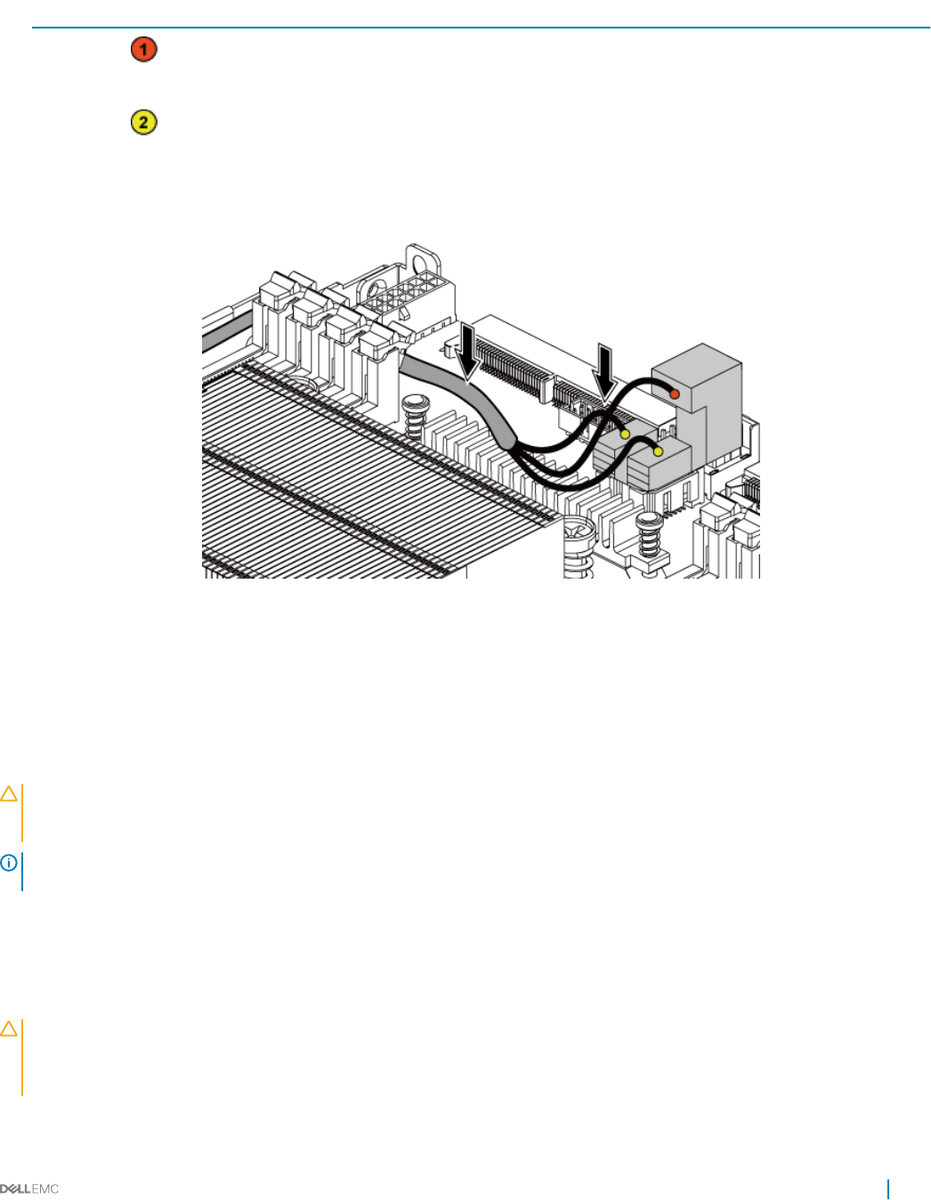
Table 33. Cable routing for onboard SATA cables (1U node)
Item Cable From (system board) To (system board)
Onboard SATA cable Onboard SATA output
connector 0
SAS/SATA input connector 0
Onboard SATA cable Onboard SATA connectors 4&5 SAS/SATA input connectors
4&5
2 Press down on the cables, and ensure the cables are routed lower than the height of the processor heat sinks.
Figure 63. Cable routing down for onboard SATA cables (1U node)
Trusted Platform Module
Trusted Platform Module (TPM) is a dedicated microprocessor designed to secure hardware by integrating cryptographic keys into devices.
A software can use a Trusted Platform Module to authenticate hardware devices. As each TPM chip has a unique and secret RSA key
burned in as it is produced, it can perform the platform authentication.
CAUTION: Do not attempt to remove the Trusted Platform Module (TPM) from the system board. After the TPM is installed, it is
cryptographically bound to that specic system board. Any attempt to remove an installed TPM breaks the cryptographic
binding, and it cannot be re-installed or installed on another system board.
NOTE: This is a Field Replaceable Unit (FRU). Removal and installation procedures must be performed only by Dell certied
service technicians.
Installing the Trusted Platform Module
Prerequisites
CAUTION: Many repairs may only be done by a certied service technician. You should only perform troubleshooting and simple
repairs as authorized in your product documentation, or as directed by the online or telephone service and support team. Damage
due to servicing that is not authorized by Dell is not covered by your warranty. Read and follow the safety instructions that are
shipped with your product.
1 Follow the safety guidelines listed in the Safety instructions section.
Installing and removing system components 113
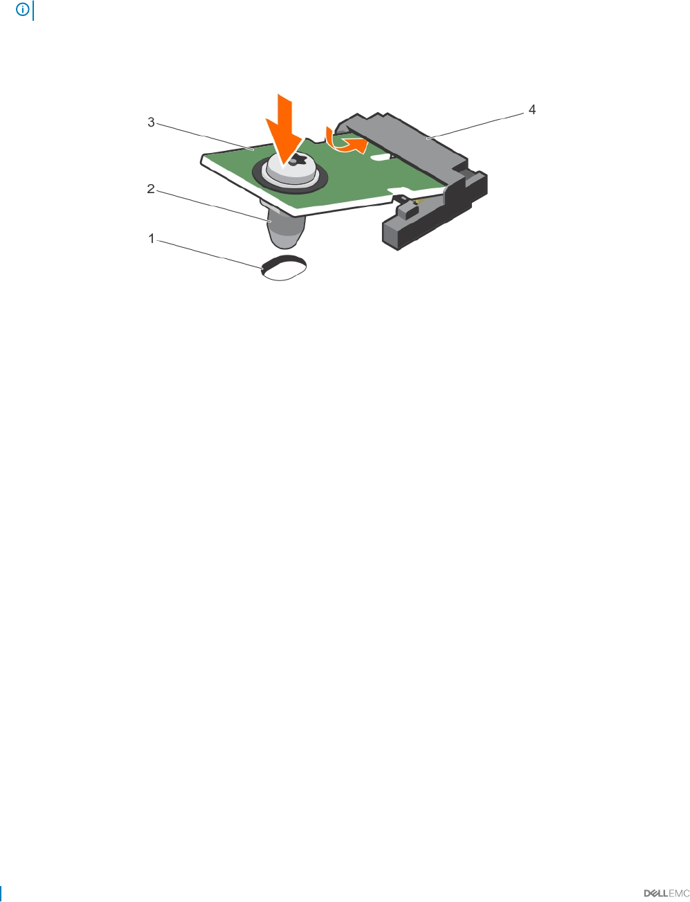
2 Follow the procedure listed in the Before working inside your system section.
Steps
1 Locate the TPM connector on the system board.
NOTE: To locate the TPM connector on the system board, see the System board connectors section.
2 Align the edge connectors on the TPM with the slot on the TPM connector.
3 Insert the TPM into the TPM connector such that the plastic rivet aligns with the slot on the system board.
4 Press the plastic rivet until the rivet snaps into place.
Figure 64. Installing the TPM
1rivet slot on the system board 2 plastic rivet
3 TPM 4 TPM connector
Next steps
1 Install the system board.
2 Follow the procedure listed in the After working inside your system section.
Initializing the TPM for BitLocker users
Initialize the TPM.
For more information about initializing the TPM, see http://technet.microsoft.com/en-us/library/cc753140.aspx.
The TPM Status changes to Enabled, Activated.
Initializing the TPM for TXT users
1 While booting your system, press F2 to enter System Setup.
2 On the System Setup Main Menu screen, click System BIOS → System Security Settings.
3 From the TPM Security option, select On with Pre-boot Measurements.
4 From the TPM Command option, select Activate.
5 Save the settings.
6 Restart your system.
7 Enter System Setup again.
8 On the System Setup Main Menu screen, click System BIOS → System Security Settings.
9 From the Intel TXT option, select On.
114 Installing and removing system components
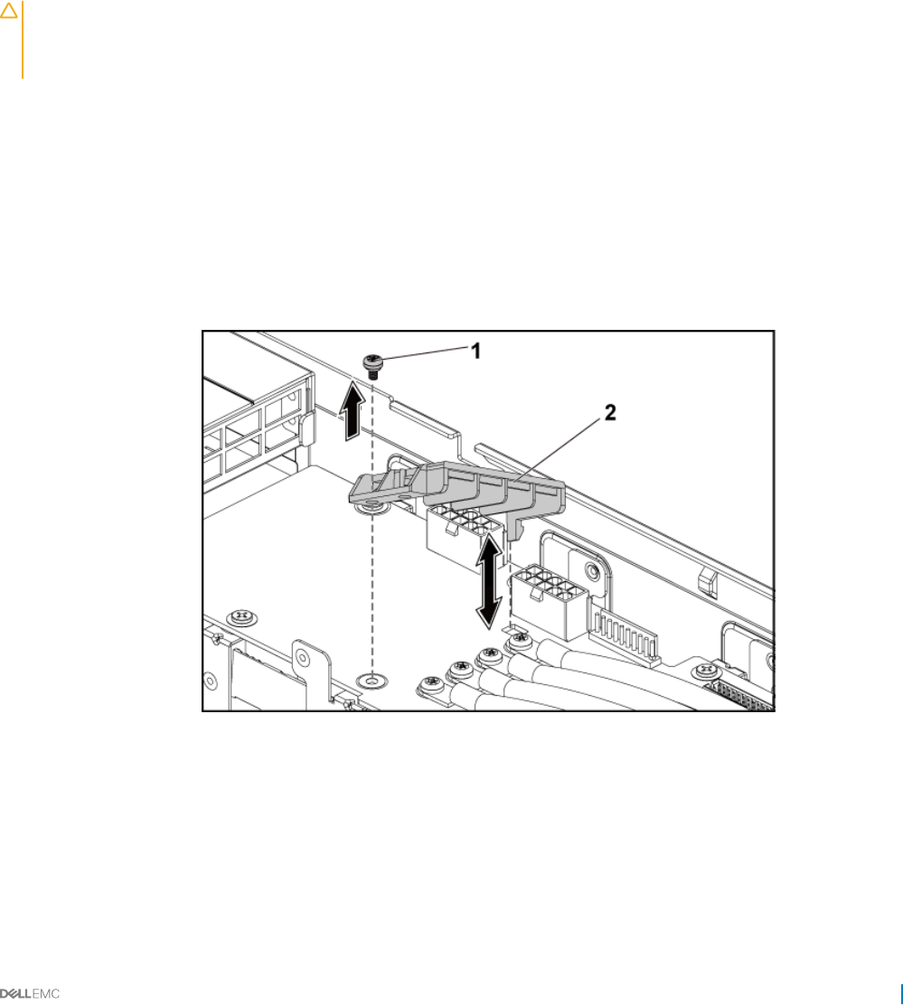
Power distribution boards
The power distribution board is a board that connects the redundant power supplies to the system board. The power distribution board
(PDB) is only supported in systems with redundant power supplies. This system has two power distribution boards (PDB). The procedure
to remove and install both the power PDBs is similar. To access the PDB 2 at the bottom, remove the PDB 1 at the top.
Removing the power distribution board 1
Prerequisites
CAUTION: Many repairs may only be done by a certied service technician. You should only perform troubleshooting and simple
repairs as authorized in your product documentation, or as directed by the online or telephone service and support team. Damage
due to servicing that is not authorized by Dell is not covered by your warranty. Read and follow the safety instructions that are
shipped with your product.
1 Follow the safety guidelines listed in the Safety instructions section.
2 Follow the procedure listed in the Before working inside your system section.
3 Remove the power supply units.
Steps
1 Disconnect all the cables from the power distribution board 1 (PDB 1).
Observe the routing of the cable on the chassis as you remove them from the system. You must route these cables properly when you
replace them to prevent the cables from being pinched or crimped.
2 Remove the screw that secures the power cable cover to the PDB 1.
3 Lift it up straight from the locking hole on the PDB 1. Then, lift it completely out of the PDB 1.
Figure 65. Removing and installing the power cable cover
1screw 2 power cable cover
4 Remove the screws that secure the power cables to the PDB 1.
Installing and removing system components 115
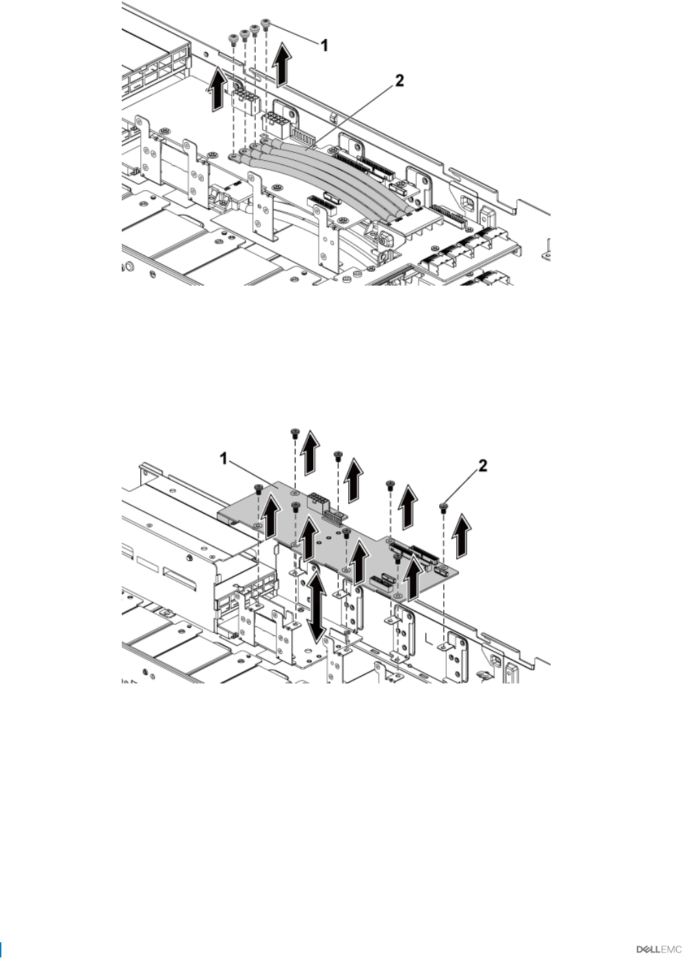
Figure 66. Removing and installing the power cables
1 screw (4) 2 power cables (4)
5 Remove the screws that secure the PDB 1 to the system.
6 Lift the PDB 1 away from the system.
Figure 67. Removing and installing the PDB 1
1PDB 1 2 screw (8)
7 Lift the PDB connector from the system.
8 Disconnect all the cables from the PDB 2.
9 Remove the power cable cover from the PDB 2.
10 Remove the four power cables from the PDB 2.
11 Remove the screws that secure the PDB 2 to the system.
12 Lift the PDB 2 out of the system.
116 Installing and removing system components
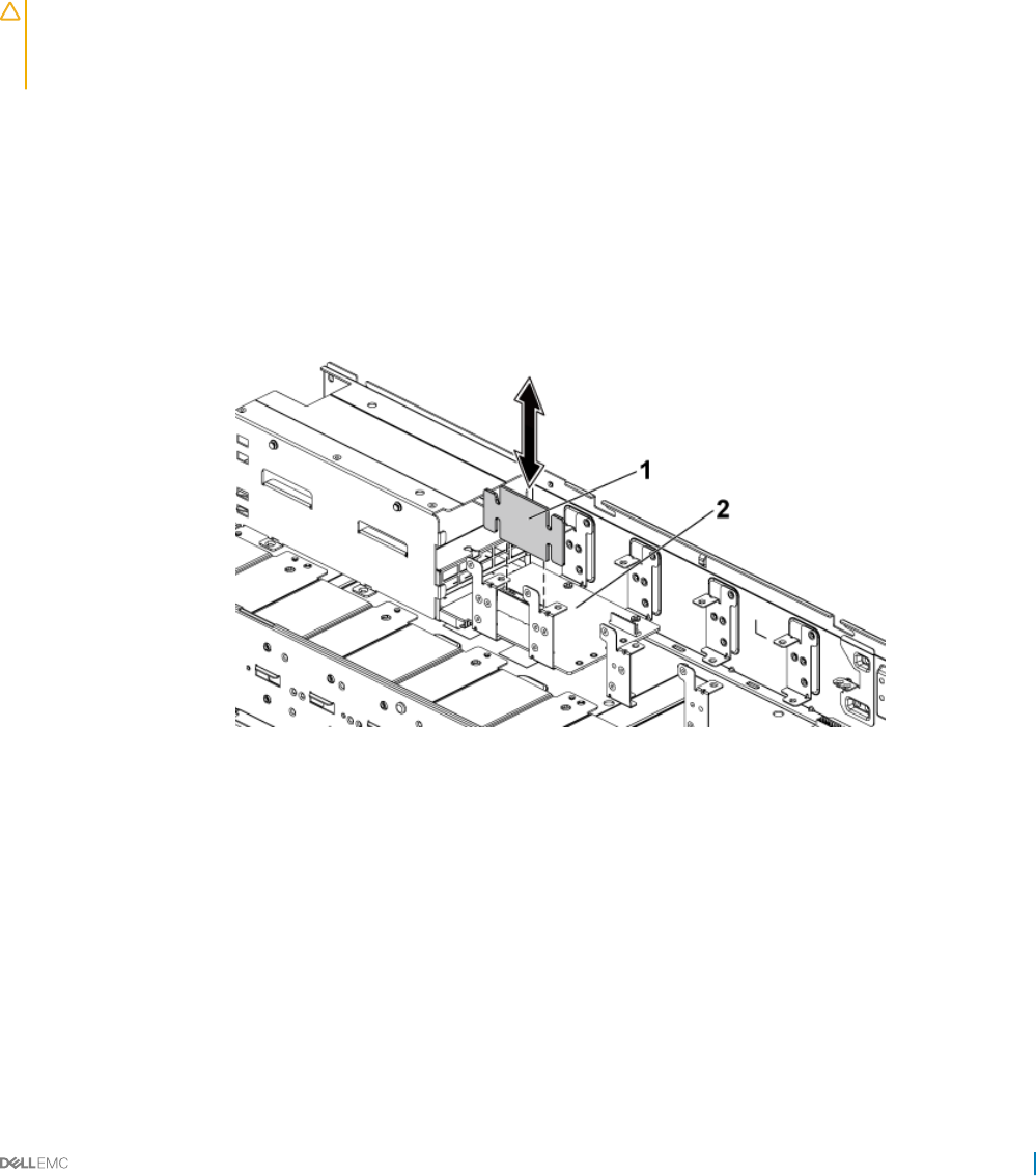
Related links
Safety instructions
Before working inside your system
Removing the system cover
Installing the power distribution board 1
Removing the power distribution board 2
Prerequisites
CAUTION: Many repairs may only be done by a certied service technician. You should only perform troubleshooting and simple
repairs as authorized in your product documentation, or as directed by the online or telephone service and support team. Damage
due to servicing that is not authorized by Dell is not covered by your warranty. Read and follow the safety instructions that are
shipped with your product.
1 Follow the safety guidelines listed in the Safety instructions section.
2 Follow the procedure listed in the Before working inside your system section.
3 Remove the power supply units.
4 Remove the power distribution board 1 (PDB 1)
Steps
1 Lift the PDB connector from the system.
Figure 68. Removing and installing the PDB connector
1PDB connector 2 PDB 2
2 Disconnect all the cables from the PDB 2.
3 Remove the screw that secures the power cable cover to the PDB.
4 Remove the power cable cover from the PDB 2.
5 Remove the screws that secure the power cables to the PDB 2
6 Remove the screws that secure the PDB 2 to the system.
7 Lift the PDB 2 out of the system.
Installing and removing system components 117
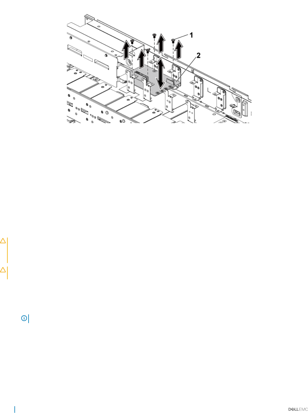
Figure 69. Removing and installing a PDB 2
1 screw (4) 2 PDB 2
Related links
Safety instructions
Before working inside your system
Removing the system cover
Removing the power distribution board 2
Installing the power distribution board 2
Prerequisites
CAUTION: Many repairs may only be done by a certied service technician. You should only perform troubleshooting and simple
repairs as authorized in your product documentation, or as directed by the online or telephone service and support team. Damage
due to servicing that is not authorized by Dell is not covered by your warranty. Read and follow the safety instructions that are
shipped with your product.
CAUTION: If removed, you must replace the power distribution board 2 (PDB 2) and the power distribution board-connector
before replacing the power distribution board 1 (PDB 1).
Follow the safety guidelines listed in the Safety instructions section.
Steps
1 Align the screw holes on the PDB 2 with the holes on the chassis.
NOTE: To install the PDB 2, angle the board during installation.
2 Install the screws that secure the PDB 2 to the system.
3 Install the power distribution board connector.
4 Connect the power cables to the PDB 2 by using screws.
5 Connect all the other cables to the PDB 2.
You must route these cables properly through the tabs on the chassis to prevent them from being pinched or crimped.
Next steps
Install the PDB 1
118 Installing and removing system components

Related links
Safety instructions
Installing the power distribution board 1
After working inside your system
Installing the power distribution board 1
Prerequisites
CAUTION: Many repairs may only be done by a certied service technician. You should only perform troubleshooting and simple
repairs as authorized in your product documentation, or as directed by the online or telephone service and support team. Damage
due to servicing that is not authorized by Dell is not covered by your warranty. Read and follow the safety instructions that are
shipped with your product.
CAUTION: If removed, you must replace the power distribution board 2 (PDB 2) and the power distribution board-connector
before replacing the power distribution board 1 (PDB 1).
Follow the safety guidelines listed in the Safety instructions section.
Steps
1 Lower the PDB 1 such that the slot at the bottom of the PDB 1 inserts into the PDB connector on the PDB 2.
When the slot at the bottom of the PDB 1 inserts into the PDB connector on the PDB 2, the screw holes align with the holes on the
chassis.
2 Install the screws that secure the PDB 1 to the system.
3 Secure the power cables to the PDB 1 by using the screws.
4 Connect all the cables to the PDB 1.
You must route these cables properly through the tabs on the chassis to prevent them from being pinched or crimped.
Next steps
1 Install the power supply units.
2 Follow the procedure listed in the After working inside your system section.
Related links
Safety instructions
Installing the system cover
After working inside your system
Installing and removing system components 119
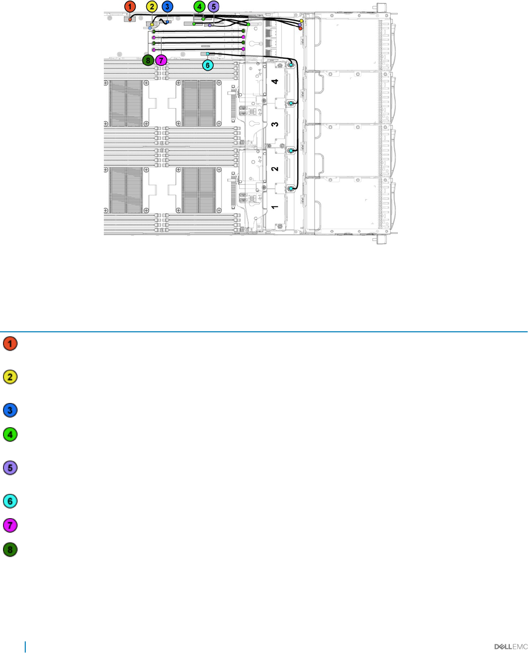
Cable routing for the power distribution boards
Figure 70. Cable routing−power distribution board 1 (top view)
Table 34. Cable routing−power distribution board 1 (top view)
Item Cable From (power distribution
boards)
To
Hard-drive backplane power
cable
Hard-drive backplane power
connector (J84)
Backplane
Hard-drive backplane power
cable
Hard-drive backplane power
connector (J29)
Backplane
Power distribution board cable Control connector (J31) Power distribution board 2
I2C cables System board control connectors
(J5&J6)
Midplanes
Backplane control cable Hard-drive backplane control
connector (J17)
Backplane
System fan cable System fan connector (J9) Cooling fans
12 V power cables Power distribution board 1/2 Midplanes
Ground power cables Power distribution board 1/2 Midplanes
120 Installing and removing system components
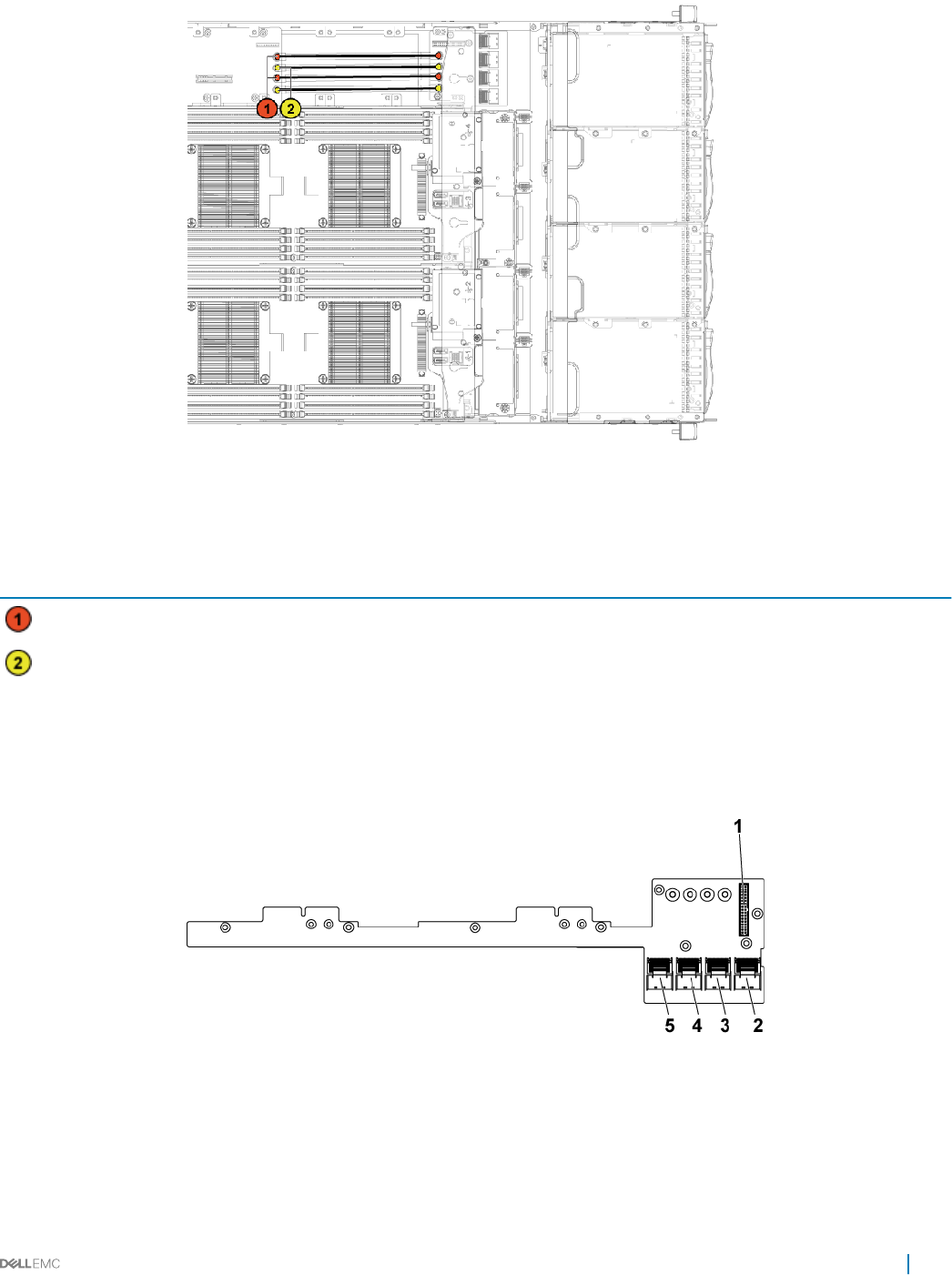
Figure 71. Cable routing−power distribution board 2 (bottom)
Table 35. Cable routing−power distribution board 2 (bottom)
Item Cable From (power distribution board
2)
To
Ground power cables Power distribution board 1/2 Midplanes
12V power cables Power distribution board 1/2 Midplanes
Midplanes
In a 3.5 inch hard drive conguration, two midplanes connect the system board to the 3.5 inch hard drive backplane. In a 2.5 inch hard drive
conguration, two midplanes connect the system boards the 2.5-inch hard drive backplane for expander conguration.
Figure 72. Midplane connectors
12x17pin control connector for power distribution board 1 2 mini-SAS connector for system board 3 and 4 (hard drive 5
and 6)
3 mini-SAS connector for system board 3 and 4 (hard drive 1, 2, 3
and 4)
4 mini-SAS connector for system board 1 and 2 (hard drive 5
and 6)
Installing and removing system components 121
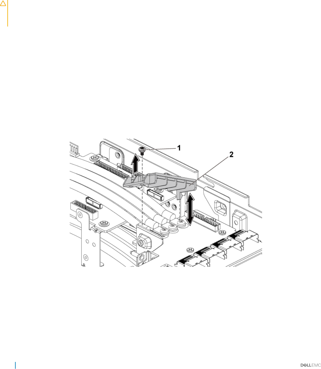
5 mini-SAS connector for system board 1 and 2 (hard drive 1, 2, 3
and 4)
Removing the midplane
Prerequisites
CAUTION: Many repairs may only be done by a certied service technician. You should only perform troubleshooting and simple
repairs as authorized in your product documentation, or as directed by the online or telephone service and support team. Damage
due to servicing that is not authorized by Dell is not covered by your warranty. Read and follow the safety instructions that are
shipped with your product.
1 Follow the safety guidelines listed in the Safety instructions section.
2 Follow the procedure listed in the Before working inside your system section.
3 Remove the system boards.
4 Remove the cooling fan cage.
Steps
1 Remove the screws that secure the middle wall bracket to the chassis.
2 Lift the middle wall bracket out of chassis.
3 Disconnect all the cables from the upper midplane.
Observe the routing of the cable on the chassis as you remove them from the system. You must route these cables properly when you
replace them to prevent the cables from being pinched or crimped.
4 Remove the screw that secures the power cable cover to the upper midplane.
5 Lift it up straight from the locking hole on the upper midplane. Then, lift it completely out of the upper midplane.
Figure 73. Removing and installing the power cable cover
1screw 2 power cable cover
6 Remove the screws that secure the power cables to the upper midplane.
122 Installing and removing system components
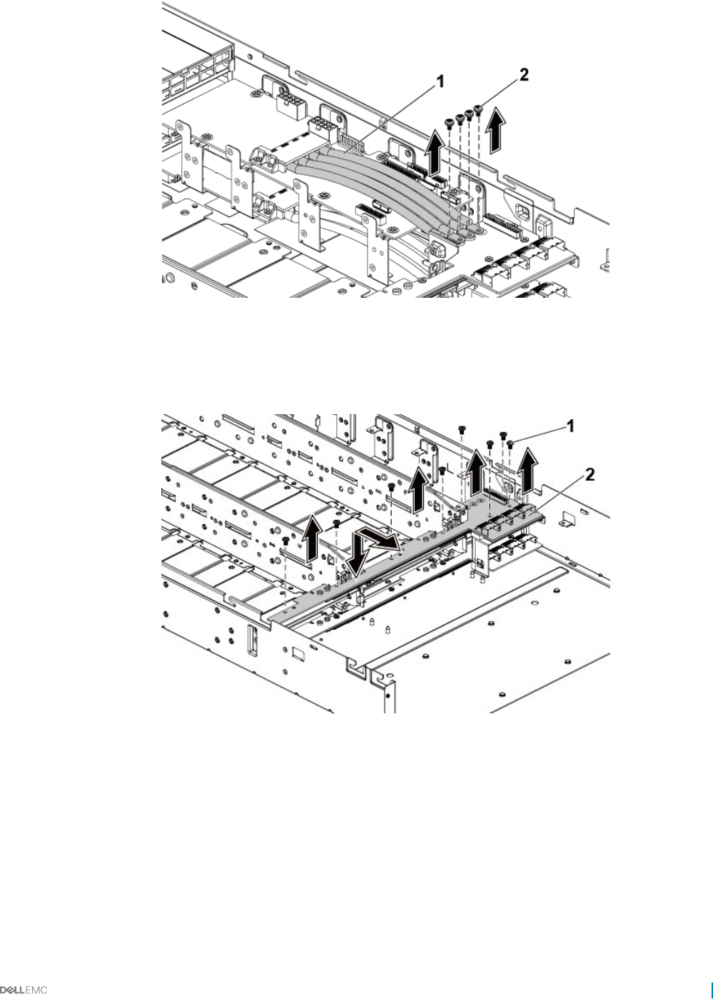
Figure 74. Removing and installing the power cables
1 power cables (4) 2 screw (4)
7 Remove the screws that secure the upper midplane to the midplane holder.
8 Lift the upper midplane out.
Figure 75. Removing and installing the upper midplane
1screw (8) 2 upper midplane
9 Remove the screws that secure the midplane holder support to the chassis.
10 Lift the midplane holder support out of the chassis.
Installing and removing system components 123
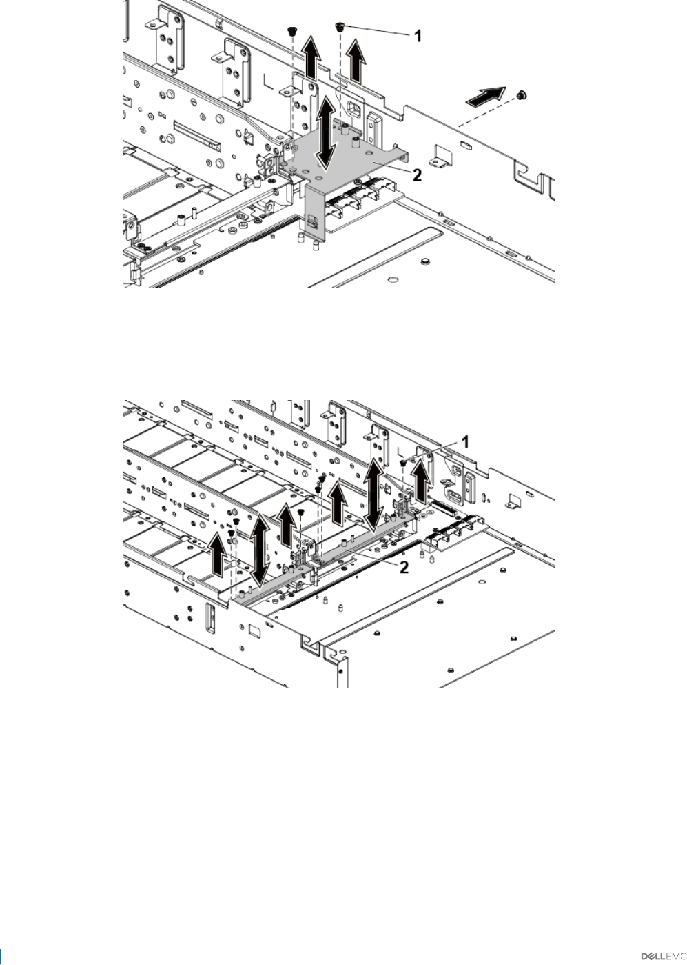
Figure 76. Removing and installing the midplane holder support
1 screw (3) 2 midplane holder support
11 Remove the screws that secure the midplane holder to the chassis.
12 Lift the midplane holder out of the chassis.
Figure 77. Removing and installing the midplane holder
1screw (6) 2 midplane holder
13 Disconnect all the cables from the lower midplane.
Note the routing of the cable on the chassis as you remove them from the system. You must route these cables properly when you
replace them to prevent the cables from being pinched or crimped.
14 Remove the power cable cover from the lower midplane.
15 Remove the four power cables from the lower midplane.
16 Remove the screws that secure the lower midplane to the chassis.
17 Lift the lower midplane out of the chassis.
124 Installing and removing system components
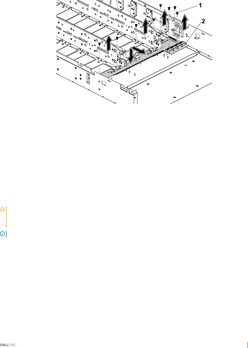
Figure 78. Removing and installing the lower midplane
1 screw (8) 2 lower midplane
Related links
Safety instructions
Before working inside your system
Removing the system cover
Removing the system board assembly
Removing a cooling fan
Installing the midplane
Prerequisites
CAUTION: Many repairs may only be done by a certied service technician. You should only perform troubleshooting and simple
repairs as authorized in your product documentation, or as directed by the online or telephone service and support team. Damage
due to servicing that is not authorized by Dell is not covered by your warranty. Read and follow the safety instructions that are
shipped with your product.
NOTE: You must route the cables properly on the chassis to prevent them from being pinched or crimped.
Follow the safety guidelines listed in the Safety instructions section.
Steps
1 Place the lower midplane into the chassis.
2 Replace the screws that secure the lower midplane to the chassis.
3 Connect all the cables to the lower midplane.
4 Secure the screws that secure the power cables to the lower midplane.
5 Replace the power cable cover to the lower midplane.
6 Place the midplane holder into the chassis.
7 Replace the screws that secure the midplane holder to the chassis.
8 Place the midplane holder support into the chassis.
9 Replace the screws that secure the midplane holder support to the chassis.
10 Place the upper midplane on the midplane holder.
Installing and removing system components 125
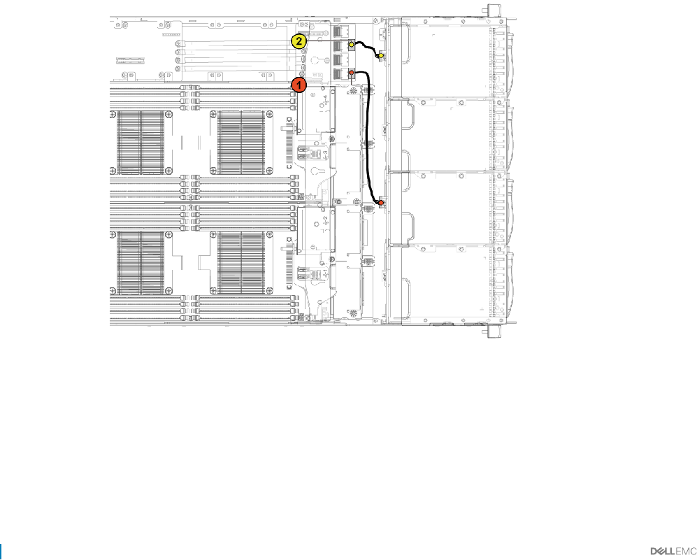
11 Replace the screws that secure the midplane to the midplane holder.
12 Connect all the cables to the upper midplane.
13 Secure the screws that secure the power cables to the upper midplane.
14 Replace the power cable cover to the upper lower midplane.
15 Place the middle wall bracket into the chassis.
16 Replace the screws that secure the middle wall bracket to the chassis.
17 Replace the cooling fan cage.
Replace the cooling fans.
Next steps
1 Replace the system boards.
2 Follow the procedure listed in the After working inside your system section.
Related links
Safety instructions
Installing a cooling fan
Installing the system board assembly
Installing the system cover
After working inside your system
Cable routing–midplane to the hard drive backplane
Figure 79. Cable routing−top midplane to backplane for 12 x3.5-inch hard drive conguration
126 Installing and removing system components
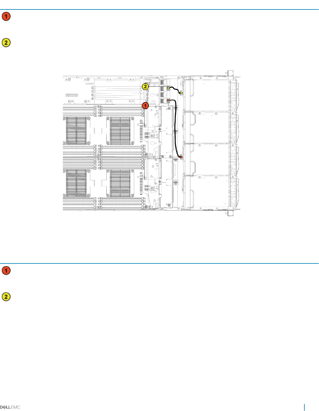
Table 36. Cable routing−bottom midplane to backplane for 12 x3.5-inch hard drive conguration
Item Cable From (top midplane) To (backplane)
Hard drive backplane cable mini-SAS connector for system
board 1 (hard drive 1, 2, 3 and 4)
(J1)
SATA2 hard drive connectors 1, 2
and 3 for system board 1 (from
top to bottom)
Hard drive backplane cable mini-SAS connector for system
board 3 (hard drive 1, 2, 3 and 4)
(J3)
SATA2 hard drive connectors 1, 2
and 3 for system board 3 (from
top to bottom)
Figure 80. Cable routing−bottom midplane to backplane for 12 x3.5-inch hard drive congurations
Table 37. Cable routing−bottom midplane to backplane for 12 x3.5-inch hard drive congurations
Item Cable From (bottom midplane) To (backplane)
Hard drive backplane cable mini-SAS connector for system
board 2 (hard drive 1, 2, 3 and 4)
(J1)
SATA2 hard drive connectors 1, 2
and 3 for system board 2 (from
top to bottom)
Hard drive backplane cable mini-SAS connector for system
board 4 (hard drive 1, 2, 3 and 4)
(J3)
SATA2 hard drive connectors 1,
2, and 3 for system board 4
(from top to bottom)
Installing and removing system components 127
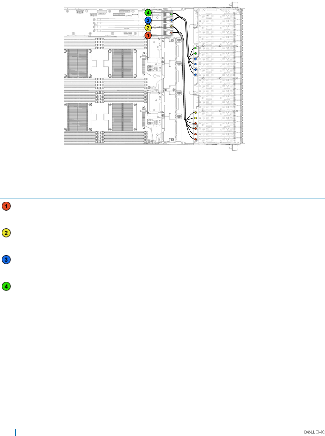
Figure 81. Cable routing−top midplane to backplane for 24 x2.5-inch hard drive conguration
Table 38. Cable routing−top midplane to backplane for 24 x2.5-inch hard drive conguration
Item Cable From (top midplane) To (backplane)
Hard drive backplane cable Mini-SAS connector for system
board 1 (hard drive 1, 2, 3 and 4)
(J1)
SATA2 hard drive connectors 1
to 4 for system board 1 (from
right to left)
Hard drive backplane cable Mini-SAS connector for system
board 1 (hard drive 5 and 6) (J2)
SATA2 hard drive connectors 5
to 6 for system board 1 (from
right to left)
Hard drive backplane cable Mini-SAS connector for system
board 3 (hard drive 1, 2, 3 and 4)
(J3)
SATA2 hard drive connectors 1
to 4 for system board 3 (from
right to left)
Hard drive backplane cable Mini-SAS connector for system
board 3 (hard drive 5 and 6) (J4)
SATA2 hard drive connectors 5
to 6 for system board 3 (from
right to left)
128 Installing and removing system components
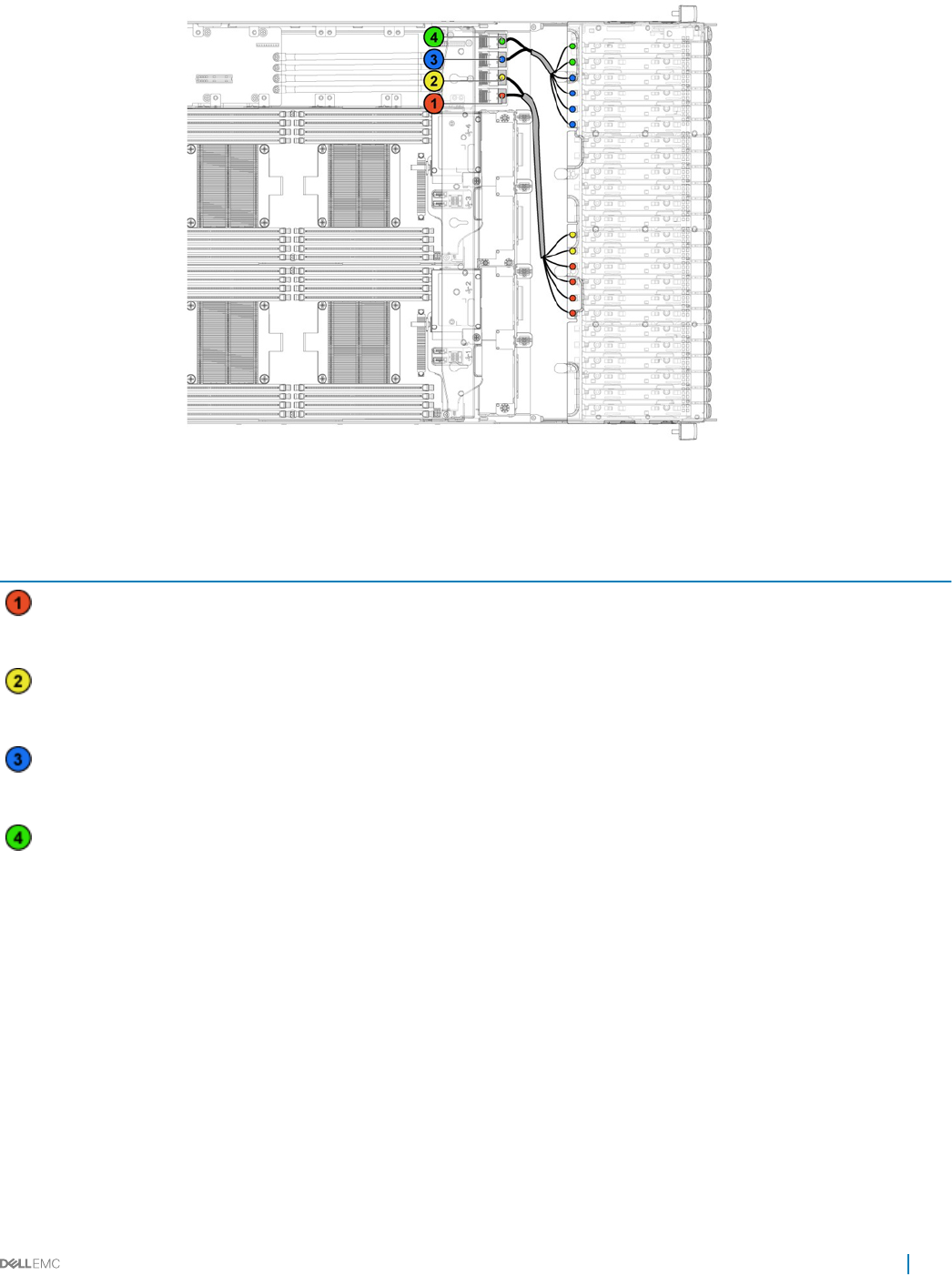
Figure 82. Cable routing−bottom midplane to backplane for 24 x2.5-inch hard drive conguration
Table 39. Cable routing−bottom midplane to backplane for 24 x2.5-inch hard drive conguration
Item Cable From (bottom midplane) To (backplane)
Hard drive backplane cable Mini-SAS connector for system
board 2 (hard drive 1, 2, 3 and 4)
(J1)
SATA2 hard drive connectors 1
to 4 for system board 2 (from
right to left)
Hard drive backplane cable Mini-SAS connector for system
board 2 (hard drive 5 and 6) (J2)
SATA2 hard drive connectors 5
to 6 for system board 2 (from
right to left)
Hard drive backplane cable Mini-SAS connector for system
board 4 (hard drive 1, 2, 3 and 4)
(J3)
SATA2 hard drive connectors 1
to 4 for system board 4 (from
right to left)
Hard drive backplane cable Mini-SAS connector for system
board 4 (hard drive 5 and 6) (J4)
SATA2 hard drive connectors 5
to 6 for system board 4 (from
right to left)
Installing and removing system components 129
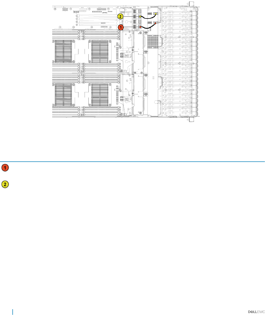
Cable routing for middle plane to 2.5-inch hard drive backplane
for expander conguration
Figure 83. Cable routing−top middle plane to 2.5-inch hard drive for expander conguration
Table 40. Cable routing−top middle plane to 2.5-inch hard drive for expander conguration
Item Cable From (top middle plane) To (expander card)
Hard drive backplane cable Mini-SAS connector for system
board 1 (J3)
Mini-SAS connector ( 0-3) for
system board 1
Hard drive backplane cable Mini-SAS connector for system
board 3 (J5)
Mini-SAS connector (8-11) for
system board 3
130 Installing and removing system components
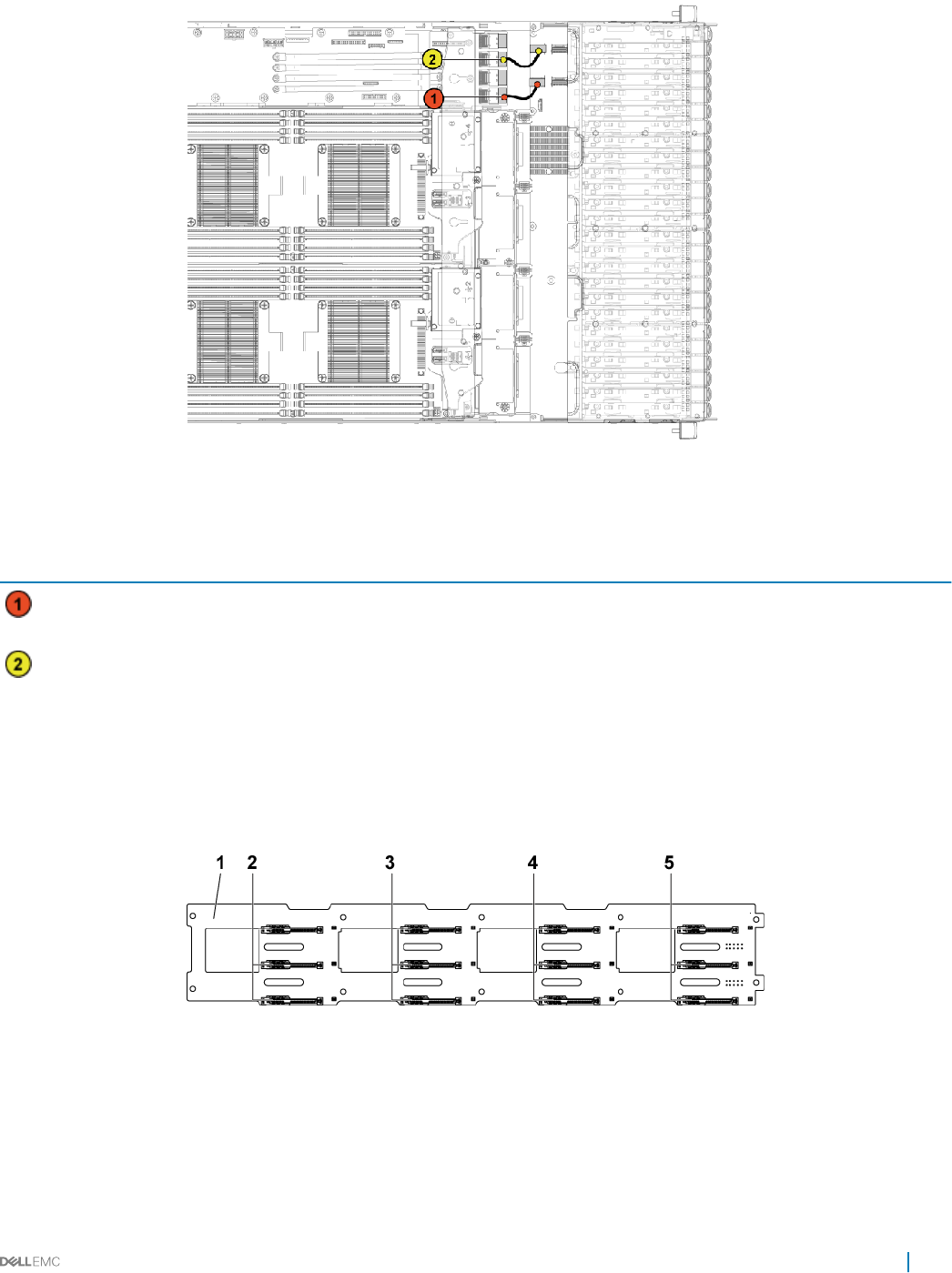
Figure 84. Cable routing−bottom middle plane to 2.5-inch hard drive for expander conguration
Table 41. Cable routing−bottom middle plane to 2.5-inch hard drive for expander conguration
Item Cable From (bottom middle plane) To (expander card)
Hard drive backplane cable Mini-SAS connector for system
board 2 (J4)
Mini-SAS connector (4-7) for
system board 2
Hard drive backplane cable Mini-SAS connector for system
board 4 (J6)
Mini-SAS connector (12-15) for
system board 4
Hard drive backplanes
Servers use a backplane to attach hot swappable hard drives. A backplane has pins that pass directly into hard drive sockets without
cables. They may have single connector to connect one disk array controller or multiple connectors that can be connected to one or more
controllers.
Figure 85. Front view of the 3.5 inch hard drive backplane
13.5 inch backplane 2 hard drive connectors 1, 2 and 3 for system board 1 (from top
to bottom)
3 hard drive connectors 1, 2 and 3 for system board 2 (from top
to bottom)
4 hard drive connectors 1, 2 and 3 for system board 3 (from
top to bottom)
5 hard drive connectors 1, 2 and 3 for system board 4 (from top
to bottom)
Installing and removing system components 131
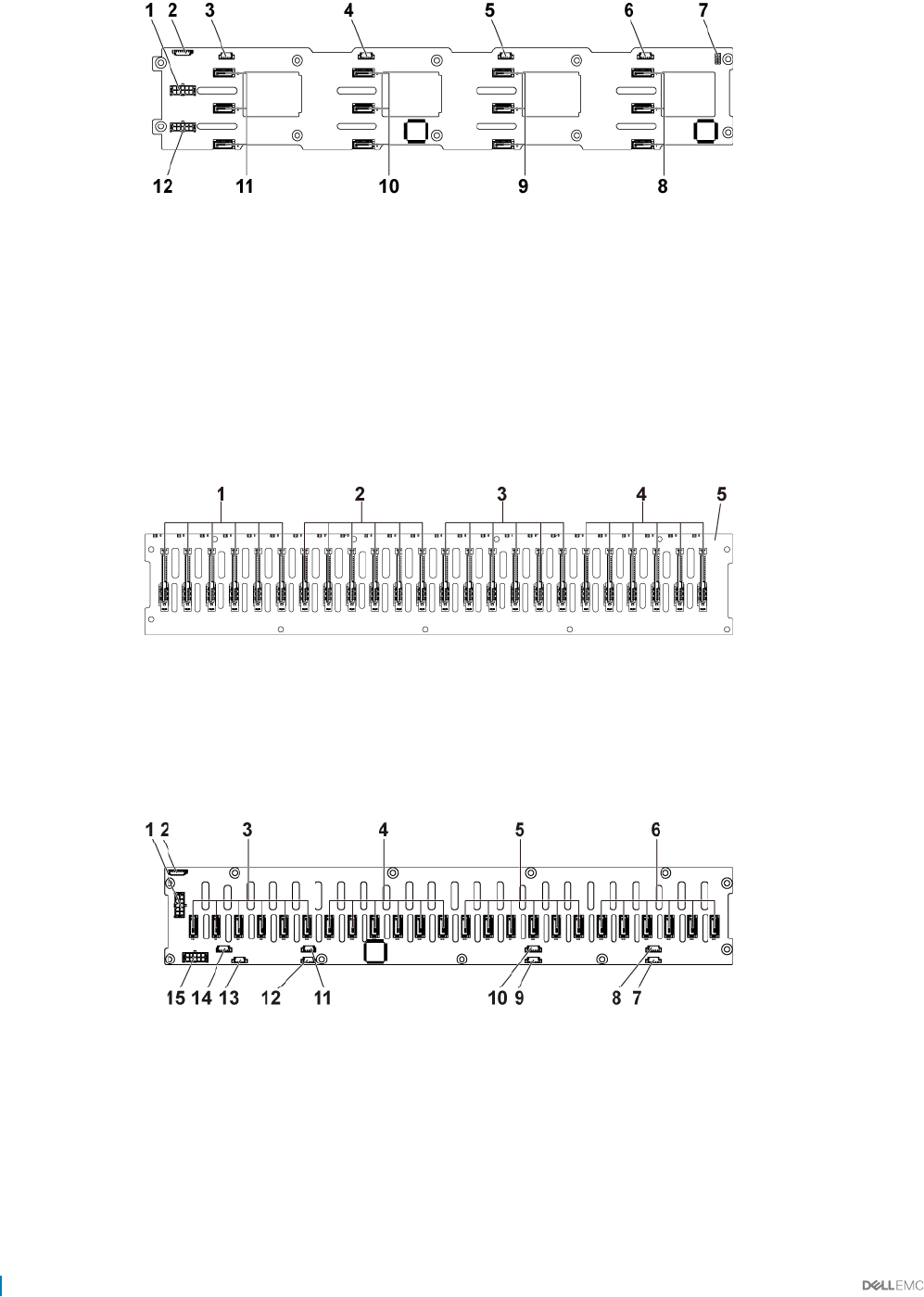
Figure 86. Back view of the 3.5 inch hard drive backplane
1 backplane power connector for power supply unit 1 2 1x8pin fan controller board connector
3 SGPIO connector 4 for system board 4 4 SGPIO connector 3 for system board 3
5 SGPIO connector 2 for system board 2 6 SGPIO connector 1 for system board 1
7 backplane jumper 8 SATA2 and SAS connectors 1, 2 and 3 for system board 1
(from top to bottom)
9 SATA2 and SAS connectors 1, 2 and 3 for system board 2 (from
top to bottom)
10 SATA2 and SAS connectors 1, 2 and 3 for system board 3
(from top to bottom)
11 SATA2 and SAS connectors 1, 2 and 3 for system board 4 (from
top to bottom)
12 backplane power connector for power supply unit 2
Figure 87. Front view of the 2.5 inch hard drive backplane
1hard drive connectors 1 to 6 for system board 1 (from left to
right)
2 hard drive connectors 1 to 6 for system board 2 (from left to
right)
3 hard drive connectors 1 to 6 for system board 3 (from left to
right)
4 hard drive connectors 1 to 6 for system board 4 (from left to
right)
5 2.5-inch backplane
Figure 88. Back view of the 2.5 inch hard drive backplane
1backplane power connector for power supply 1 2 system fan board connector
3 SATA2 and SAS connectors 1 to 6 for system board 4 (from
right to left)
4 SATA2 and SAS connectors 1 to 6 for system board 3 (from
right to left)
5 SATA2 and SAS connectors 1 to 6 for system board 2 (from
right to left)
6 SATA2 and SAS connectors 1 to 6 for system board 1 (from
right to left)
7 SGPIO connector A for system board 1 8 SGPIO connector B for system board 1
132 Installing and removing system components

9 SGPIO connector A for system board 2 10 SGPIO connector B for system board 2
11 SGPIO connector A for system board 3 12 SGPIO connector B for system board 3
13 SGPIO connector A for system board 4 14 SGPIO Connector B for system board 4
15 backplane power connector for power supply 2
Removing the hard drive backplane
Prerequisites
CAUTION: Many repairs may only be done by a certied service technician. You should only perform troubleshooting and simple
repairs as authorized in your product documentation, or as directed by the online or telephone service and support team. Damage
due to servicing that is not authorized by Dell is not covered by your warranty. Read and follow the safety instructions that are
shipped with your product.
CAUTION: To prevent damage to the drives and backplane, you must remove the hard drives from the system before removing
the backplane.
CAUTION: You must note the number of each hard drive and temporarily label them before removal so that you can replace them
in the same locations.
NOTE: The removal procedure for 2.5-inch of SATA2 and SAS backplane is similar to the backplane for 3.5-inch hard drive
systems.
NOTE: Observe the routing of the cable on the chassis as you remove them from the system. You must route these cables
properly when you replace them to prevent the cables from being pinched or crimped.
1 Follow the safety guidelines listed in the Safety instructions section.
2 Follow the procedure listed in the Before working inside your system section.
3 Remove all the hard drives.
Steps
1 Disconnect all the cables from the backplane.
2 Disconnect the control panel cables from the power distribution board.
3 Remove the screws that secure the hard drive cage to the chassis.
Installing and removing system components 133
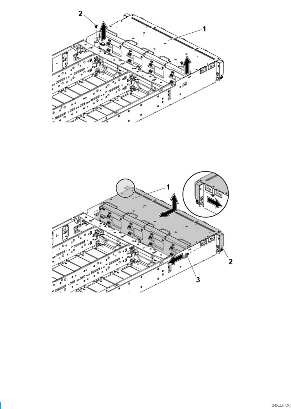
Figure 89. Removing and installing the backplane
1 hard drive cage 2 screw (2)
4 Remove the screws that secure the control panel to the chassis.
5 Remove the hard drive cage from the chassis.
Figure 90. Removing and installing the hard drive cage
1hard drive cage 2 control panel assembly (2)
3 screw (2)
6 Remove the screws that secure the backplane to the hard drive cage.
7 Remove the backplane from the hard drive cage.
134 Installing and removing system components
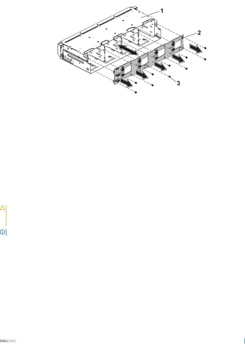
Figure 91. Removing and installing the backplane from the hard drive cage
1 hard drive cage 2 3.5-inch backplane
3 screw (10)
Related links
Safety instructions
Before working inside your system
Removing a hard drive
Removing the system cover
Installing the hard drive backplane
Prerequisites
CAUTION: Many repairs may only be done by a certied service technician. You should only perform troubleshooting and simple
repairs as authorized in your product documentation, or as directed by the online or telephone service and support team. Damage
due to servicing that is not authorized by Dell is not covered by your warranty. Read and follow the safety instructions that are
shipped with your product.
NOTE: You must route the cables properly through the tabs on the chassis to prevent them from being pinched or crimped.
Follow the safety guidelines listed in the Safety instructions section.
Steps
1 Install the backplane into the hard drive cage.
2 Install the screws that secure the backplane to the hard drive cage.
3 Install the hard drive cage into the chassis.
4 Install the screws that secure the control panel assemblies to the chassis.
5 Connect all the cables to the backplane.
Next steps
1 Connect the control panel cables to the power distribution board.
2 Install the screws that secure the hard drive cage.
3 Install the hard drives.
Installing and removing system components 135
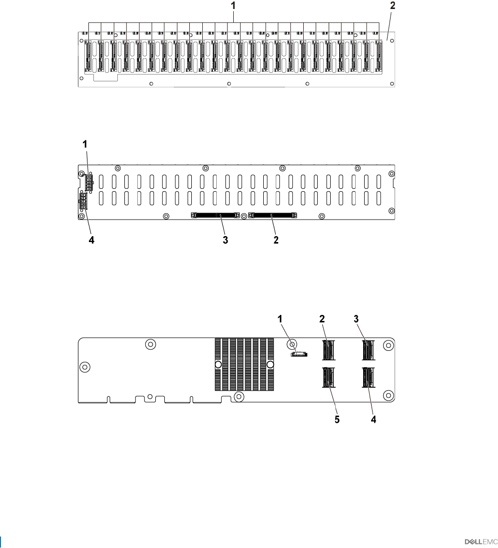
4 Follow the procedure listed in the After working inside your system section.
Related links
Safety instructions
Installing the system cover
Installing a hard drive into a hard drive carrier
After working inside your system
2.5-inch hard drive expander conguration
In a 2.5 inch hard drive conguration, an expander card connects the system boards to the 2.5-inch hard drive backplane through the
midplane.
Figure 92. Front view of the backplane
1 hard drive connectors 1 to 24 (from left to right) 2 2.5 inch backplane for expander conguration
Figure 93. Back view of the backplane
1backplane power connector for power supply 1 2 expander-card connector 1
3 expander-card connector 2 4 backplane power connector for power supply 2
Figure 94. Top view of the 2.5-inch hard drive expander card
1power control connector 2 mini-SAS connector (4-7)
3 mini-SAS connector (12-15) 4 mini-SAS connector (8-11)
5 mini-SAS connector (0-3)
136 Installing and removing system components
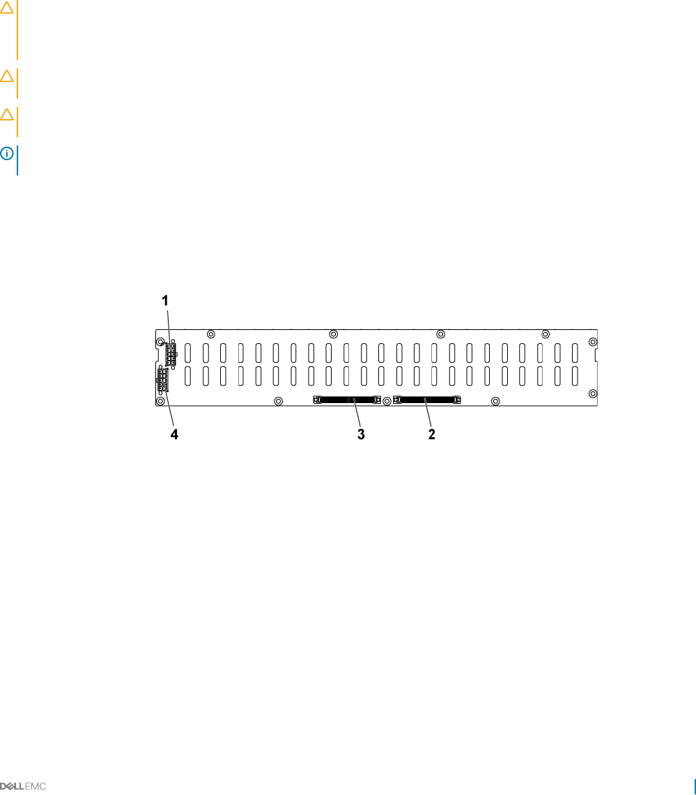
Following is the replacement procedure of SATA2 and SAS backplane for the 2.5-inch hard drive expander conguration. The conguration
is applicable for up to four system boards and supports up to 24 hard drives. For more information, see the HDD Zoning conguration tool
under Drivers & downloads at Dell.com/support.
Removing the 2.5-inch hard drive backplane for expander
conguration
Prerequisites
CAUTION: Many repairs may only be done by a certied service technician. You should only perform troubleshooting and simple
repairs as authorized in your product documentation, or as directed by the online or telephone service and support team. Damage
due to servicing that is not authorized by Dell is not covered by your warranty. Read and follow the safety instructions that are
shipped with your product.
CAUTION: To prevent damage to the drives and backplane, you must remove the hard drives from the system before removing
the backplane.
CAUTION: You must note the number of each hard drive and temporarily label them before removal so that you can replace them
in the same locations.
NOTE: Observe the routing of the cable on the chassis as you remove them from the system. You must route these cables
properly when you replace them to prevent the cables from being pinched or crimped.
1 Follow the safety guidelines listed in the Safety instructions section.
2 Follow the procedure listed in the Before working inside your system section.
3 Remove all the hard drives.
Steps
1 Disconnect all the cables from the backplane and expander card.
Figure 95. Back view of the 2.5-inch hard drive backplane for expander conguration
1backplane power connector for power supply 1 2 Expander-card connector 1
3 Expander-card connector 2 4 backplane power connector for power supply 2
Installing and removing system components 137
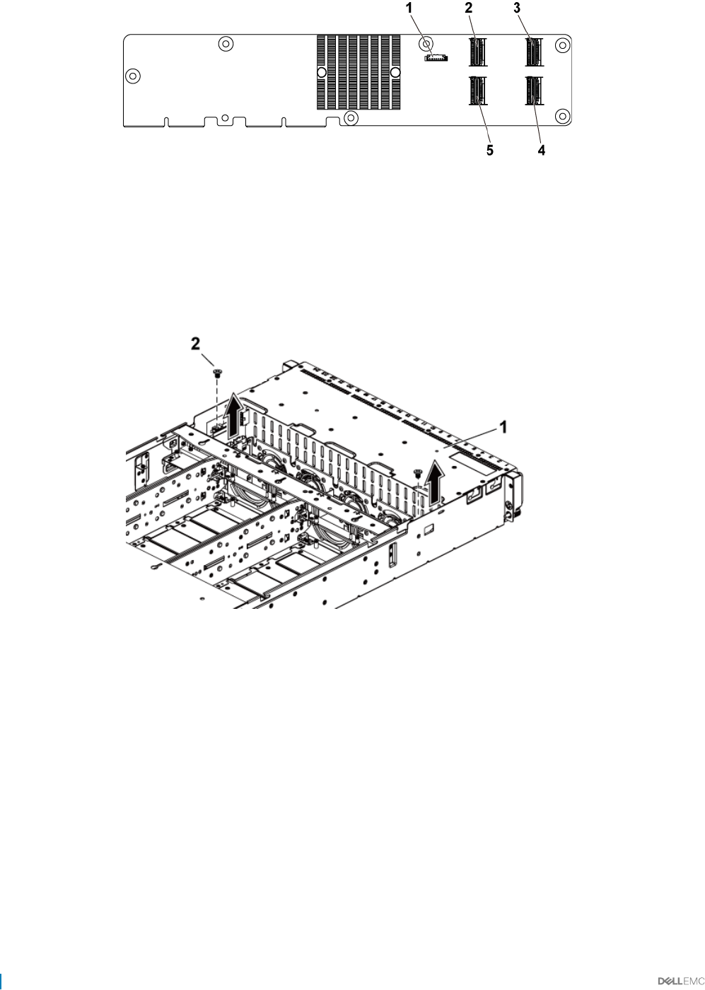
Figure 96. Top view of the expander card
1 power control connector 2 mini-SAS connector (4-7)
3 mini-SAS connector (12-15) 4 mini-SAS connector (8-11)
5 mini-SAS connector (0-3)
2 Disconnect control panel cables from the power distribution board.
3 Remove the screws that secure the hard drive cage to the chassis.
Figure 97. Removing and installing the 2.5-inch hard drive backplane for expander conguration
1hard drive cage 2 screw (2)
4 Remove the screws that secure the control panel to the chassis.
5 Remove the hard drive cage from the chassis.
138 Installing and removing system components
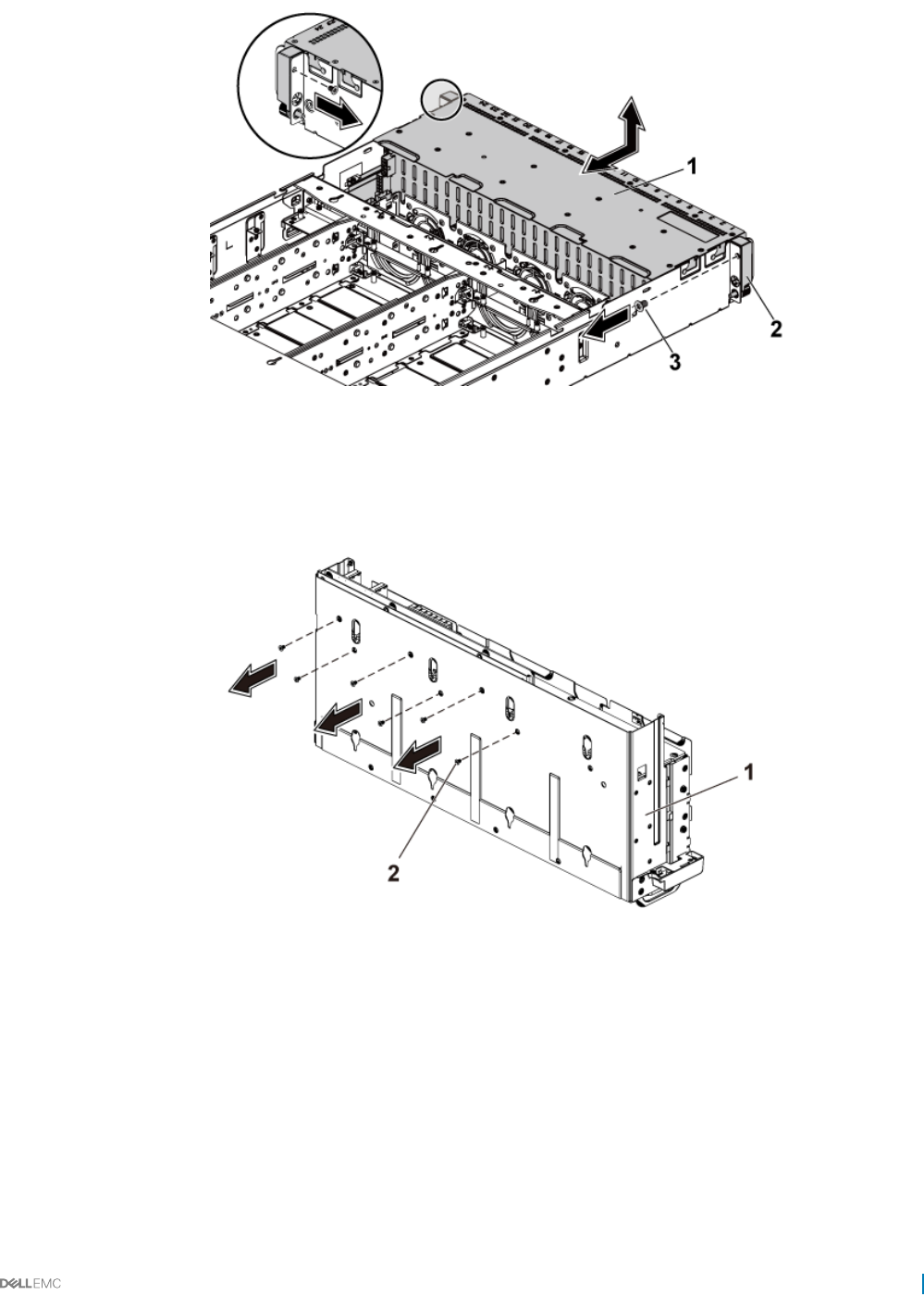
Figure 98. Removing and installing the 2.5-inch hard drive cage for expander conguration
1 hard drive cage 2 control panel assembly (2)
3 screw (2)
6 Remove the screws that secure the expander card assembly to the hard drive cage.
Figure 99. Removing and installing the screws that secure the expander card assembly to the hard drive cage
1hard drive cage 2 screw (6)
7 Remove the expander card assembly from the hard drive cage.
Installing and removing system components 139
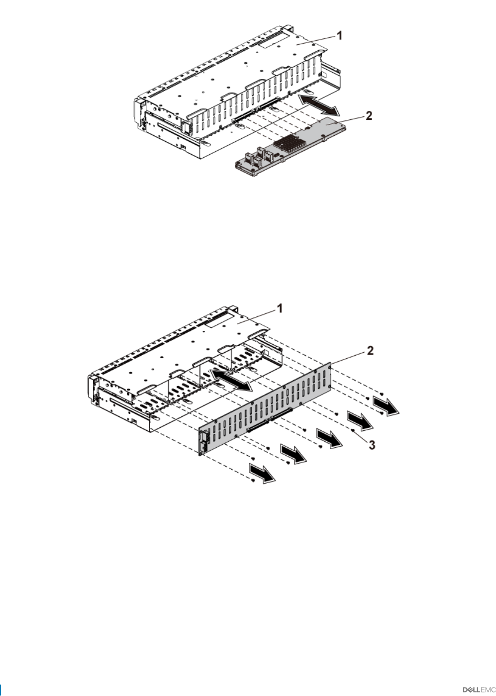
Figure 100. Removing and installing the 2.5-inch hard drive expander card assembly from the hard drive cage
1 hard drive cage 2 expander card assembly
8 Remove the screws that secure the backplane for expander conguration to the hard drive cage.
9 Remove the backplane for expander conguration from the hard drive cage.
Figure 101. Removing and installing the backplane for expander conguration from the hard drive cage
1hard drive cage 2 2.5-inch hard drive backplane for expander
conguration
3 screw (11)
Related links
Safety instructions
Before working inside your system
Removing a hard drive
Removing the system cover
140 Installing and removing system components

Installing the 2.5-inch hard drive backplane for expander
conguration
Prerequisites
CAUTION: Many repairs may only be done by a certied service technician. You should only perform troubleshooting and simple
repairs as authorized in your product documentation, or as directed by the online or telephone service and support team. Damage
due to servicing that is not authorized by Dell is not covered by your warranty. Read and follow the safety instructions that are
shipped with your product.
NOTE: You must route these cables properly through the tabs on the chassis to prevent them from being pinched or crimped.
Follow the safety guidelines listed in the Safety instructions section.
Steps
1 Install the backplane for expander conguration to the hard drive cage.
2 Install the screws that secure the backplane for expander conguration to the hard drive cage.
3 Install the expander card assembly to the hard drive cage.
4 Install the screws that secure the expander card assembly to the hard drive cage.
5 Install the hard drive cage into the chassis.
6 Install the screws that secure the control panel assemblies to the chassis.
7 Connect all the cables to the backplane for expander conguration and expander card.
8 Connect control panel cables to the power distribution board.
9 Replace the screws that secure the hard drive cage.
Next steps
1 Install the hard drives.
2 Follow the procedure listed in the After working inside your system section.
Related links
Safety instructions
Installing the system cover
Installing a hard drive into a hard drive carrier
After working inside your system
Control panel
A control panel allows you to manually control the inputs to the server. Normally the control panel has USB and VGA ports, along with the
NMI button, power button, and an optional LCD display unit or diagnostic indicators.
Removing the control panel
Prerequisites
CAUTION: Many repairs may only be done by a certied service technician. You should only perform troubleshooting and simple
repairs as authorized in your product documentation, or as directed by the online or telephone service and support team. Damage
due to servicing that is not authorized by Dell is not covered by your warranty. Read and follow the safety instructions that are
shipped with your product.
NOTE: Observe the routing of the cable on the chassis as you remove them from the system. You must route these cables
properly when you replace them to prevent the cables from being pinched or crimped.
Installing and removing system components 141
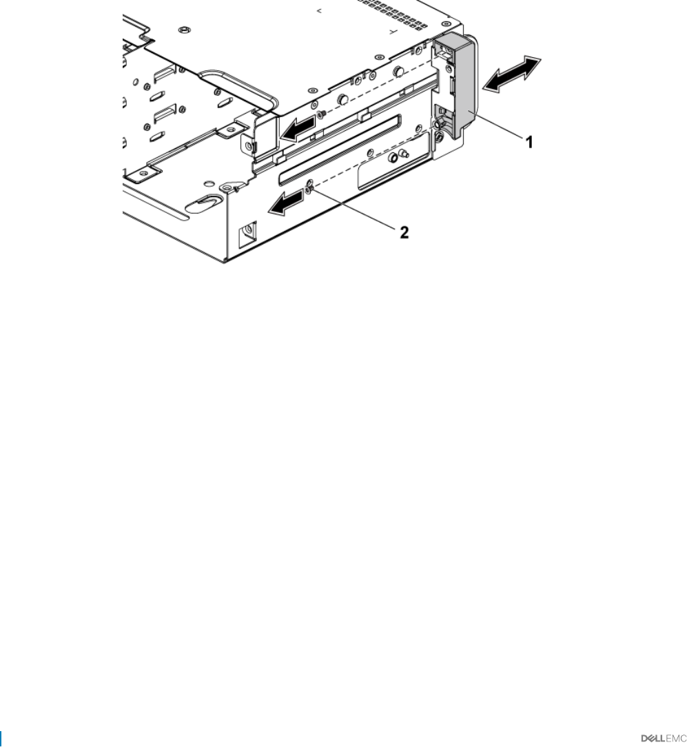
1 Follow the safety guidelines listed in the Safety instructions section.
2 Follow the procedure listed in the Before working inside your system section.
3 Remove all the hard drives.
4 Disconnect all the cables from the backplane.
5 Disconnect control panel cables from the power distribution board.
6 Remove the screws that secure the hard drive cage to the chassis.
Steps
1 Remove the screws that secure the control panel assemblies to the chassis.
2 Remove the hard drive cage from the chassis.
3 Remove the screws that secure the control panel assembly to the hard drive cage.
4 Remove the control panel assembly from the hard drive cage.
Figure 102. Removing and installing a control panel assembly
1control panel assembly 2 screw (2)
5 Push aside the retention hooks on the control panel assembly.
6 Remove the control panel from the control panel assembly.
142 Installing and removing system components
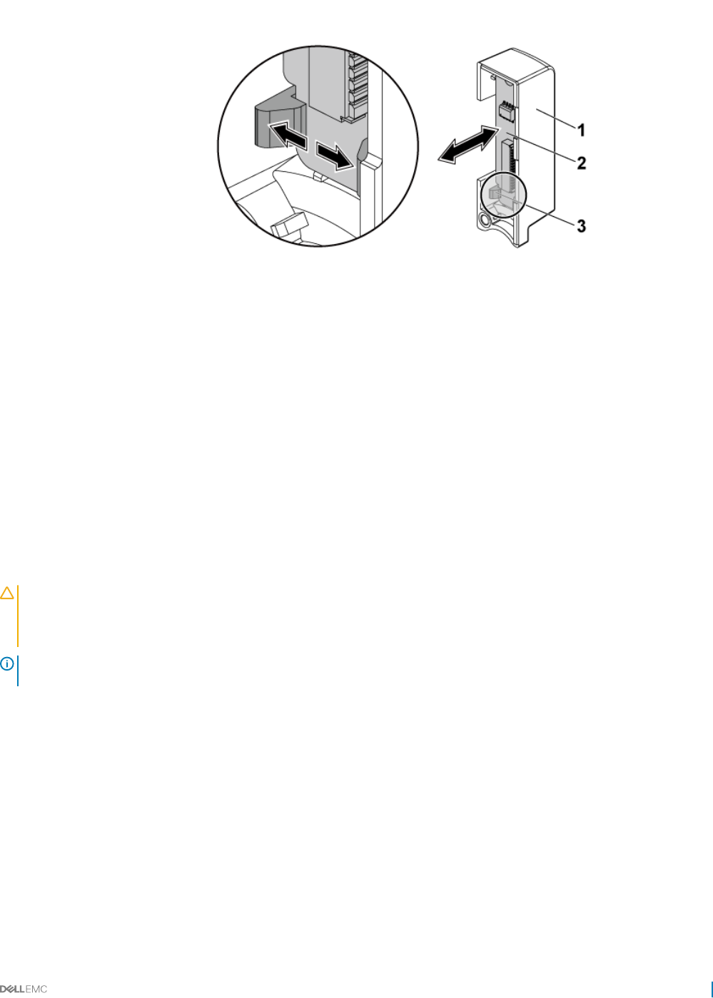
Figure 103. Removing and installing a control panel
1 control panel assembly 2 control panel
3 retention hooks
Related links
Safety instructions
Before working inside your system
Removing a hard drive
Removing the system cover
Installing the control panel
Prerequisites
CAUTION: Many repairs may only be done by a certied service technician. You should only perform troubleshooting and simple
repairs as authorized in your product documentation, or as directed by the online or telephone service and support team. Damage
due to servicing that is not authorized by Dell is not covered by your warranty. Read and follow the safety instructions that are
shipped with your product.
NOTE: Observe the routing of the cable on the chassis as you remove them from the system. You must route these cables
properly when you replace them to prevent the cables from being pinched or crimped.
Follow the safety guidelines listed in the Safety instructions section.
Steps
1 Push aside the retention hooks on the control panel assembly and place the control panel into the control panel assembly.
2 Install the control panel assembly into the hard drive cage.
3 Install the screws that secure the control panel assembly to the hard drive cage.
4 Install the hard drive cage into the chassis.
5 Install the screws that secure the control panel assemblies to the chassis.
6 Install the screws that secure the hard drive cage to the chassis.
7 Connect the control panel cables to the power distribution board.
Next steps
1 Connect all the cables to the backplane.
Installing and removing system components 143

2 Install the system cover.
3 Install the hard drives.
4 Reconnect the system to its electrical outlet and turn on the system, including any attached peripherals.
Related links
Safety instructions
Installing the system cover
Installing a hard drive into a hard drive carrier
After working inside your system
Sensor boards
Removing the sensor board for 3.5-inch hard drive system
Prerequisites
CAUTION: Many repairs may only be done by a certied service technician. You should only perform troubleshooting and simple
repairs as authorized in your product documentation, or as directed by the online or telephone service and support team. Damage
due to servicing that is not authorized by Dell is not covered by your warranty. Read and follow the safety instructions that are
shipped with your product.
NOTE: Observe the routing of the cable on the chassis as you remove them from the system. You must route these cables
properly when you replace them to prevent the cables from being pinched or crimped.
1 Follow the safety guidelines listed in the Safety instructions section.
2 Follow the procedure listed in the Before working inside your system section.
3 Remove all the hard drives.
4 Disconnect all the cables from the backplane.
5 Disconnect front panel cables from the power distribution board.
Steps
1 Remove the hard drive cage from the chassis.
2 Disconnect the cable from the sensor board.
3 Remove the screw that secures the sensor board to the hard drive cage.
4 Remove the sensor board from the hard drive cage.
144 Installing and removing system components
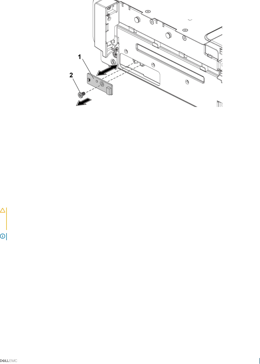
Figure 104. Removing and installing the sensor board
1 sensor board 2 screw
Related links
Safety instructions
Before working inside your system
Removing a hard drive
Removing the system cover
Installing the sensor board for 3.5-inch hard drive system
Prerequisites
CAUTION: Many repairs may only be done by a certied service technician. You should only perform troubleshooting and simple
repairs as authorized in your product documentation, or as directed by the online or telephone service and support team. Damage
due to servicing that is not authorized by Dell is not covered by your warranty. Read and follow the safety instructions that are
shipped with your product.
NOTE: You must route these cables properly on the chassis to prevent them from being pinched or crimped.
Follow the safety guidelines listed in the Safety instructions section.
Steps
1 Install the sensor board into the hard drive cage.
2 Install the screw that secures the sensor board to the hard drive cage.
3 Connect the sensor board cable to the sensor board.
Next steps
1 Install the hard drive cage into the chassis.
2 Install the screws that secure the hard drive cage to the chassis.
3 Connect all the cables to the backplane.
4 Connect front panel cables to the power distribution board.
5 Install the hard drives.
6 Follow the procedure listed in the After working inside your system section.
Installing and removing system components 145
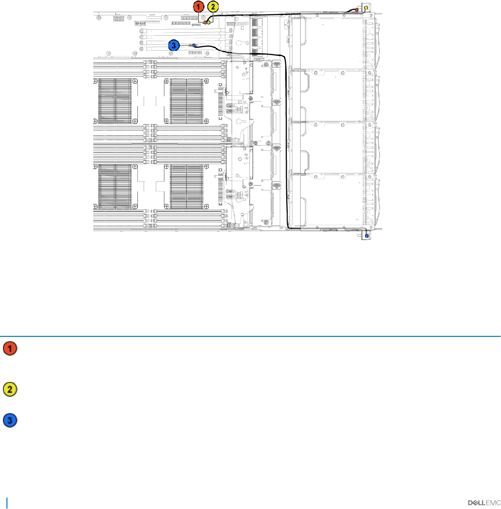
Related links
Safety instructions
Installing the system cover
Installing a hard drive into a hard drive carrier
After working inside your system
Cable routing for sensor board and control panel for 3.5-inch
hard drive system
1 Connect the Y-shaped cable for sensor board and control panel 2 to the connector on the power distribution board 1, and connect the
other two ends of the cable to the connectors on the sensor board and the control panel 2 respectively.
2 Connect the control panel cable to the connector on the power distribution board 1, and connect the other end of the cable to the
connector on the control panel 1.
Figure 105. Cable routing−sensor board and control panel
Table 42. Cable routing for sensor board and control panel for 3.5-inch hard drive system
Item Cable From (power distribution
board)
To (sensor board and control panels)
Sensor board cable Sensor board power
connector (J1)
Sensor board
Front panel cable Front panel connector (J16) Front panel 2
Front panel cable Front panel connector (J18) Front panel 1
146 Installing and removing system components
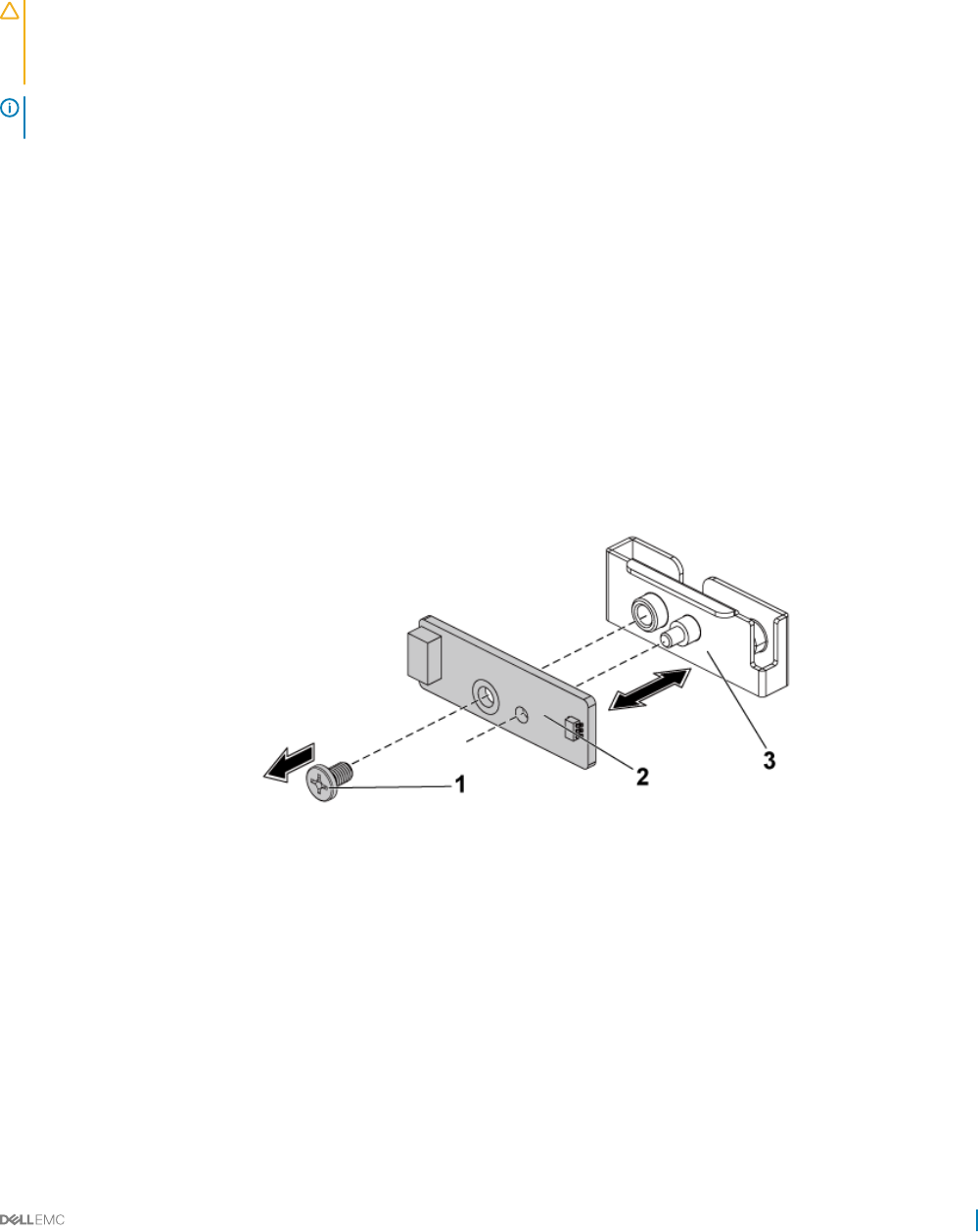
Removing the sensor board for 2.5-inch hard drive system
Prerequisites
CAUTION: Many repairs may only be done by a certied service technician. You should only perform troubleshooting and simple
repairs as authorized in your product documentation, or as directed by the online or telephone service and support team. Damage
due to servicing that is not authorized by Dell is not covered by your warranty. Read and follow the safety instructions that are
shipped with your product.
NOTE: Observe the routing of the cable on the chassis as you remove them from the system. You must route these cables
properly when you replace them to prevent the cables from being pinched or crimped.
1 Follow the safety guidelines listed in the Safety instructions section.
2 Follow the procedure listed in the Before working inside your system section.
3 Remove all the hard drives.
4 Disconnect all the cables from the backplane.
5 Disconnect control panel cables from the power distribution board.
6 Remove the hard drive cage from the chassis.
Steps
1 Disconnect the cable from the sensor board assembly.
2 Remove the screw that secures the sensor board assembly to the hard drive cage.
3 Remove the sensor board assembly from the hard drive cage.
4 Remove the screw that secures the sensor board to the sensor board holder.
5 Remove the sensor board from the sensor board holder.
Figure 106. Removing and installing the sensor board
1screw 2 sensor board
3 sensor board holder
Related links
Safety instructions
Before working inside your system
Removing a hard drive
Removing the system cover
Installing and removing system components 147

Installing the sensor board for 2.5-inch hard drive system
Prerequisites
CAUTION: Many repairs may only be done by a certied service technician. You should only perform troubleshooting and simple
repairs as authorized in your product documentation, or as directed by the online or telephone service and support team. Damage
due to servicing that is not authorized by Dell is not covered by your warranty. Read and follow the safety instructions that are
shipped with your product.
NOTE: You must route these cables properly on the chassis to prevent them from being pinched or crimped.
Follow the safety guidelines listed in the Safety instructions section.
Steps
1 Replace the sensor board into the sensor board holder.
2 Replace the sensor board assembly into the hard drive cage.
3 Replace the screw that secures the sensor board to the hard drive cage.
4 Connect the sensor board cable to the sensor board.
Next steps
1 Replace the hard drive cage into the chassis.
2 Replace the screws that secure the hard drive cage to the chassis.
3 Connect all the cables to the backplane.
4 Connect the control panel cables to the power distribution board.
5 Install the hard drives.
6 Follow the procedure listed in the After working inside your system section.
Related links
Safety instructions
Installing the system cover
Installing a hard drive into a hard drive carrier
After working inside your system
Cable routing for sensor board and control panel for 2.5-inch
hard drive system
1 Connect the Y-shaped cable for the sensor board and control panel 2 to the connector on the power distribution board 1, and connect
the other two ends of the cable to the connectors on the sensor board and the control panel 2 respectively.
2 Connect the control panel cable to the connector on the power distribution board 1, and connect the other end of the cable to the
connector on the control panel 1.
148 Installing and removing system components
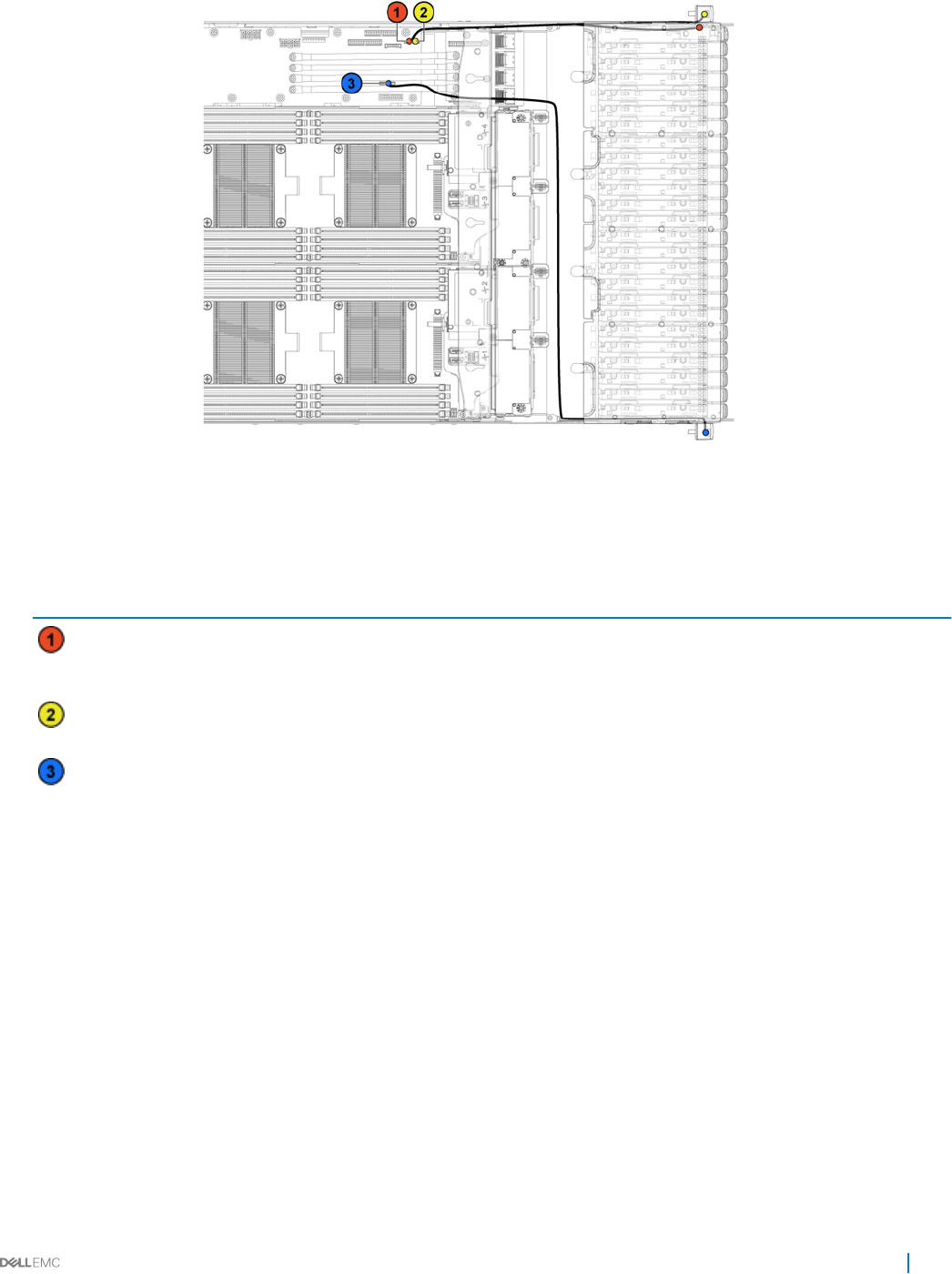
Figure 107. Cable routing−sensor board and control panel
Table 43. Cable routing−sensor board and control panel
Item Cable From (power distribution
board)
To (sensor board and control panels)
Sensor board cable Sensor board power
connector (J1)
Sensor board
Front panel cable Front panel connector (J16) Front panel 2
Front panel cable Front panel connector (J18) Front panel 1
Installing and removing system components 149
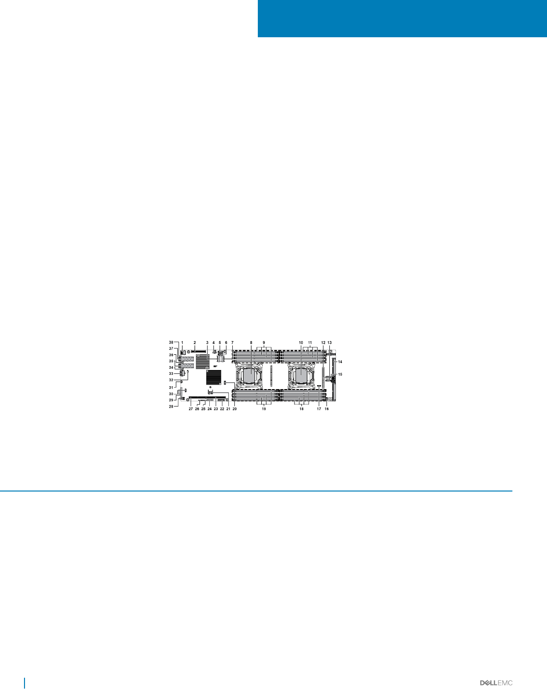
Jumpers and connectors
This topic provides specic information about the system jumpers. It also provides some basic information about jumpers and switches and
describes the connectors on the various boards in the system. Jumpers on the system board help to disable system and setup passwords.
You must know the connectors on the system board to install components and cables correctly.
Topics:
• C6320 system board connectors
• LSI 2008 SAS mezzanine card connectors
• Powerville dual port 1GbE
• Twinville dual port 10GbE
• Power distribution board 1 connectors
• Power distribution board 2 connectors
• Sensor board connectors
• Jumper settings
C6320 system board connectors
Figure 108. C6320 system board connectors
Table 44. System board connectors
Item Connector Description
1 USB1 Rear USB connector 1
2 PCIE_G3_X8 (CPU1) PCI-E Gen3 x8 mezzanine slot 3 (processor 1)
3 miniSAS0-3 Mini-SAS connector 0-3
4 HDD POWER CON Hard drive power connector
5 SATA4 Onboard SATA connector 4
6 SATA5 Onboard SATA connector 5
7 miniSAS6-9 Mini-SAS connector 6-9
8 CPU1 Processor 1
9 DIMM_A1, DIMM_A5, DIMM_A2, DIMM_A6 DIMM sockets for processor 1
7
150 Jumpers and connectors

Item Connector Description
10 CPU2 Processor 2
11 DIMM_B1, DIMM_B5, DIMM_B2, DIMM_B6 DIMM sockets for processor 2
12 SATA5 SAS/SATA connector 5
13 SATA4 SAS/SATA connector 4
14 CONTROL_PANEL Middle plane connector
15 miniSAS0-3 Mini-SAS HD connector 0-3
16 HI_PWR_CONN High-power connector
17 SGPIO Serial General Purpose Input/Output (SGPIO) connector
18 DIMM_B8, DIMM_B4, DIMM_B7, DIMM_B3 DIMM sockets for processor 2
19 DIMM_A8, DIMM_A4, DIMM_A7, DIMM_A3 DIMM sockets for processor 1
20 J106 Internal USB connector 2 (left) and USB connector 3
(right)
21 TPM Trusted Platform Module (TPM) connector
22 BHI System battery
23 PCIE_G3_X16 (CPU1) PCI-e Gen3 x16 slot 1 (processor 1)
24 CPLD_DBG CPLD debug connector
25 UART Universal Asynchronous Receiver/Transmitter (UART)
connector
26 CPLD_JTAG Complex Programmable Logic Device (CPLD) JTAG
connector
27 PCIE_G3_X16 (CPU1) PCI-E Gen3 x16 Slot 2 (processor 1)
28 SW2 Power button
29 VGA1 VGA port
30 INT_TTL Internal TTL COM connector
31 USB_DBG1 USB to serial port
32 MGMT LAN management connector
33 LAN3(BMC) Management port
34 CR21 LAN 2 LED
35 LAN2 LAN 2 port
36 CR20 LAN 1 LED
37 LAN1 LAN 1 port
38 CR3 UID LED
Related links
System memory
Jumpers and connectors 151
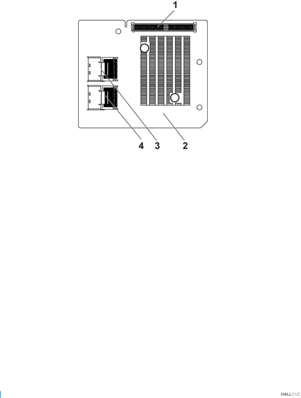
LSI 2008 SAS mezzanine card connectors
Figure 109. LSI 2008 SAS mezzanine card connectors
1mezzanine card connectors 2 LSI 2008 mezzanine card
3 mini-SAS connector (port 4-7) 4 mini-SAS connector (port 0-3)
152 Jumpers and connectors
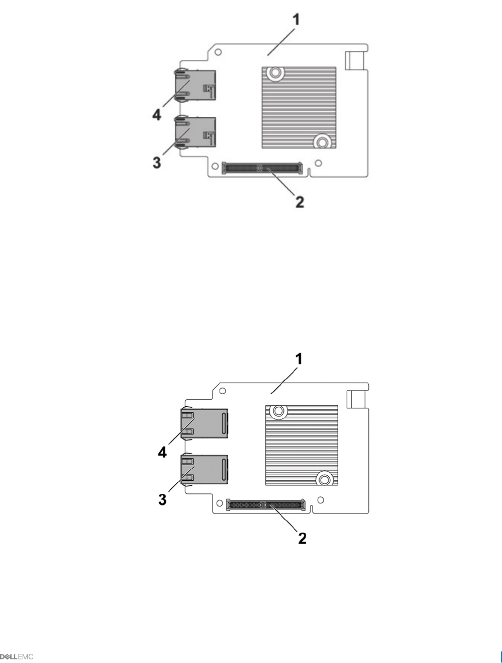
Powerville dual port 1GbE
Figure 110. Powerville dual port 1GbE connectors
1Powerville dual port 1GbE card 2 mezzanine card connector
3 NIC 1 connector 4 NIC 2 connector
Twinville dual port 10GbE
Figure 111. Twinville dual port 10GbE connectors
1Twinville dual port 10GbE card 2 mezzanine card connector
3 NIC 1 connector 4 NIC 2 connector
Jumpers and connectors 153
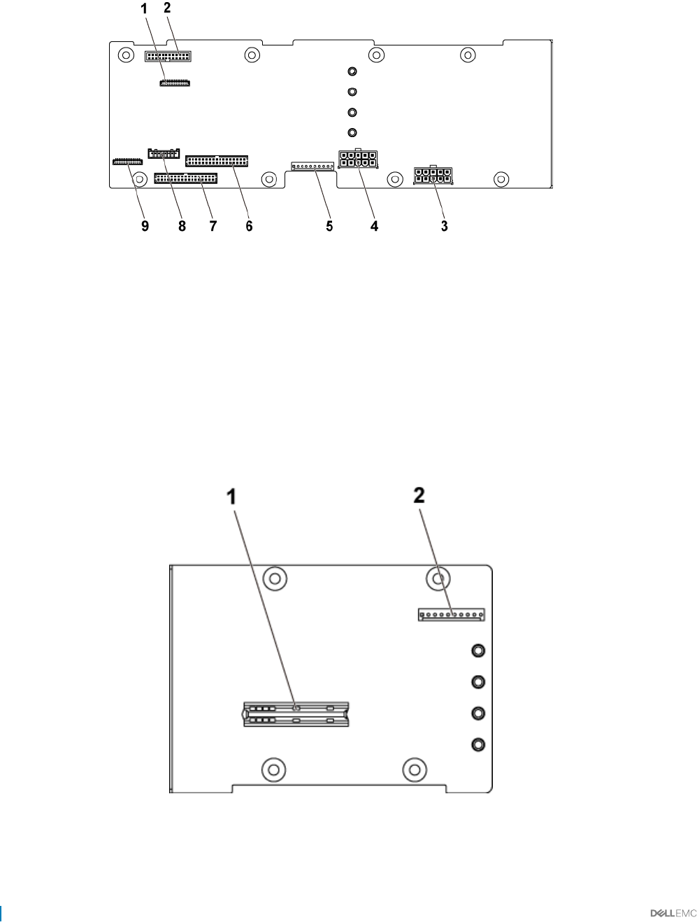
Power distribution board 1 connectors
Figure 112. Power distribution board 1 connectors
1 control panel connector for system board 1 and 2 2 system fan connector
3 hard drive backplane power connector 1 4 hard drive backplane power connector 2
5 one 10pin control connector 6 two 17pin control connector for system board 2 and 4
7 two 17pin control connector for system board
1 and 3
8 one 8pin control connector to hard drive backplane
9 control panel connector for system board 3 and 4
Power distribution board 2 connectors
Figure 113. Power distribution board 2 connectors
1bridge card connector 2 one 10pin control connector
154 Jumpers and connectors
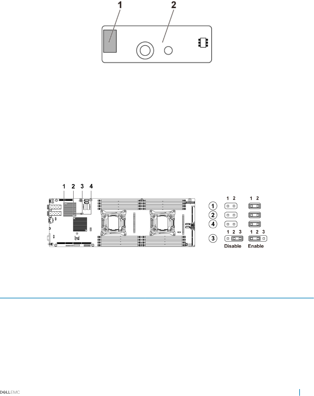
Sensor board connectors
Figure 114. Sensor board connectors
1 power connector 2 sensor board
Jumper settings
System conguration jumper settings on the C6320 system
board
The function of system conguration jumper installed on each C6320 system board is shown below:
Figure 115. System conguration jumpers on the C6320 system board
Table 45. System conguration jumper on the C6320 system board
Jumpers Function Disabled (Default state) Enabled
1BIOS Recovery No pin Pin 1-2
2NVRAM Clear No pin Pin 1-2
3PWRD_EN Pin 1-2 Pin 2-3
4ME_FM Recovery No pin Pin 1-2
Jumpers and connectors 155
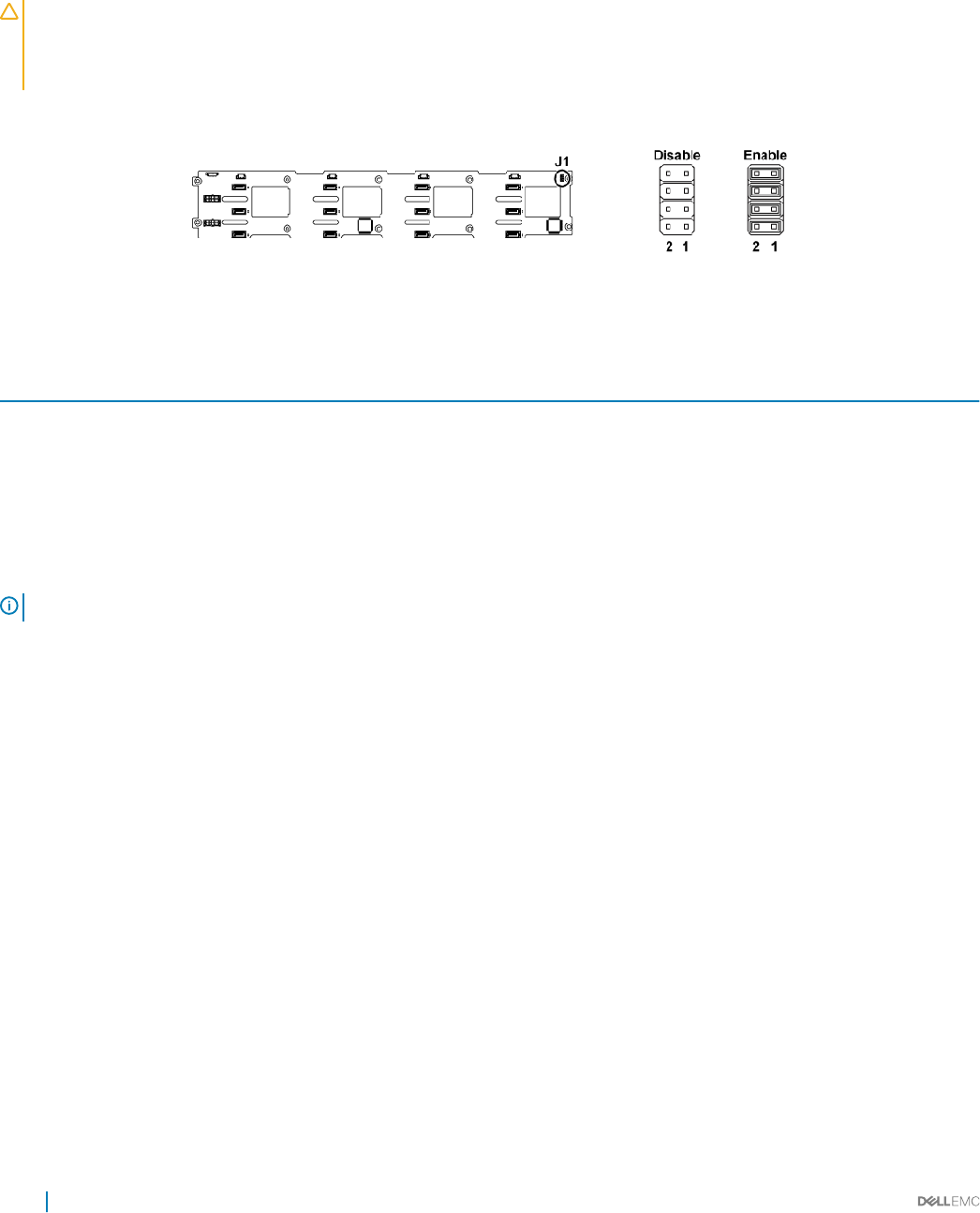
Backplane jumper settings
CAUTION: Many repairs may only be done by a certied service technician. You should only perform troubleshooting and simple
repairs as authorized in your product documentation, or as directed by the online or telephone service and support team. Damage
due to servicing that is not authorized by Dell is not covered by your warranty. Read and follow the safety instructions that are
shipped with your product.
The function of jumpers installed on 3.5-inch hard drive backplane and 2.5-inch hard drive backplane is the same. Following is an example
using the jumpers installed on 3.5-inch HDD backplane.
Figure 116. Backplane jumper settings
Table 46. Jumpers installed on backplane
Jumper Function O On
SW1 (pin1-2) Reserved Disable Enable
SW2 (pin3-4) Reserved Disable Enable
SW3 (pin5-6) SGPIO I2C Select Disable Enable
SW4 (pin7-8) MFG Test Disable Enable
NOTE: By default, the jumpers on the backplane are disabled.
156 Jumpers and connectors

Troubleshooting your system
Safety rst — for you and your system
CAUTION: Many repairs may only be done by a certied service technician. You should only perform troubleshooting and simple
repairs as authorized in your product documentation, or as directed by the online or telephone service and support team. Damage
due to servicing that is not authorized by Dell is not covered by your warranty. Read and follow the safety instructions that are
shipped with your product.
NOTE: Solution validation was performed by using the factory shipped hardware conguration.
Topics:
• Installation Problems
• Minimum conguration to POST
• Troubleshooting system startup failure
• Troubleshooting external connections
• Troubleshooting the video subsystem
• Troubleshooting a USB device
• Troubleshooting a serial I/O device
• Troubleshooting a NIC
• Troubleshooting a wet system
• Troubleshooting a damaged system
• Troubleshooting the system battery
• Troubleshooting power supply units
• Troubleshooting cooling problems
• Troubleshooting cooling fans
• Troubleshooting system memory
• Troubleshooting a hard drive
• Troubleshooting a storage controller
• Troubleshooting expansion cards
• Troubleshooting processors
Installation Problems
Perform the following checks when you troubleshoot installation problems:
• Check all cable and power connections (including all rack cable connections).
• Unplug the power cord and wait for one minute. Then reconnect the power cord and try again.
• If the network is reporting an error, verify that the system has enough memory and disk space.
• Remove all added peripherals, one at a time, and try to turn on the system. If after removing a peripheral the system works, it may be a
problem with the peripheral or a conguration problem between the peripheral and the system. Contact the peripheral vendor for
assistance.
8
Troubleshooting your system 157

• If the system does not power on, check the LED display. If the power LED is not on, you may not be receiving AC power. Check the AC
power cord to make sure that it is securely connected.
Minimum conguration to POST
The three components mentioned below are the minimum conguration to POST:
• One power supply unit
• One Processor (CPU) in socket CPU1 (minimum for troubleshooting)
• One Memory Module (DIMM) installed in the socket A1
NOTE: When PCI-E slot 1 and Mezzanine slot are to be used, processor 1 must be installed; when PCI-E slot 3 is to be used, both
processor 1 and processor 2 must be installed.
Troubleshooting system startup failure
If you boot the system to the BIOS boot mode after installing an operating system from the UEFI Boot Manager, the system stops
responding. To avoid this issue, you must boot to the same boot mode in which you installed the operating system.
For all other startup issues, note the system messages that appear on the screen.
Troubleshooting external connections
Before troubleshooting any external devices, ensure that all external cables are securely attached to the external connectors on your
system before troubleshooting any external devices.
Troubleshooting the video subsystem
Prerequisites
NOTE: Ensure the Local Server Video Enabled option is selected in the iDRAC Graphical User Interface (GUI), under Virtual
Console. If this option is not selected, local video is disabled.
Steps
1 Check the cable connections (power and display) to the monitor.
2 Check the video interface cabling from the system to the monitor.
3 Run the appropriate diagnostic test.
If the tests run successfully, the problem is not related to video hardware.
Next steps
If the tests fail, see the Getting help section.
Related links
Getting help
Troubleshooting a USB device
Prerequisites
NOTE: Follow steps 1 to 6 to troubleshoot a USB keyboard or mouse. For other USB devices, go to step 7.
Steps
1 Disconnect the keyboard and/or mouse cables from the system and reconnect them.
2 If the problem persists, connect the keyboard and/or mouse to another USB port on the system.
158 Troubleshooting your system

3 If the problem is resolved, restart the system, enter System Setup, and check if the non-functioning USB ports are enabled.
NOTE: Older operating systems may not support USB 3.0.
4 Check if USB 3.0 is enabled in System Setup. If enabled, disable it and see if the issue is resolved.
5 In iDRAC Settings Utility, ensure that USB Management Port Mode is congured as Automatic or Standard OS Use.
6 If the problem is not resolved, replace the keyboard and/or mouse with a known working keyboard or mouse.
If the problem is not resolved, proceed to step 7 to troubleshoot other USB devices attached to the system.
7 Turn o all attached USB devices, and disconnect them from the system.
8 Restart the system.
9 If your keyboard is functioning, enter System Setup, verify that all USB ports are enabled on the Integrated Devices screen. If your
keyboard is not functioning, use remote access to enable or disable the USB options.
10 Check if USB 3.0 is enabled in System Setup. If it is enabled, disable it and restart your system.
11 If the system is not accessible, reset the NVRAM_CLR jumper inside your system and restore the BIOS to the default settings. See the
System board jumper setting section
12 In the IDRAC Settings Utility, ensure that USB Management Port Mode is congured as Automatic or Standard OS Use.
13 Reconnect and turn on each USB device one at a time.
14 If a USB device causes the same problem, turn o the device, replace the USB cable with a known good cable, and turn on the
device.
Next steps
If all troubleshooting fails, see the Getting help section.
Troubleshooting a serial I/O device
Steps
1 Turn o the system and any peripheral devices connected to the serial port.
2 Swap the serial interface cable with a known working cable, and turn on the system and the serial device.
If the problem is resolved, replace the interface cable with a known working cable.
3 Turn o the system and the serial device, and swap the serial device with a compatible device.
4 Turn on the system and the serial device.
Next steps
If the problem persists, see the Getting help section.
Related links
Getting help
Troubleshooting a NIC
Steps
1 Run the appropriate diagnostic test. For more information, see the Using system diagnostics section for the available diagnostic tests.
2 Restart the system and check for any system messages pertaining to the NIC controller.
3 Check the appropriate indicator on the NIC connector:
• If the link indicator does not glow, the cable connected might be disengaged.
• If the activity indicator does not glow, the network driver les might be damaged or missing.
Install or replace the drivers as necessary. For more information, see the NIC documentation.
• If the problem persists, use another connector on the switch or hub.
4 Ensure that the appropriate drivers are installed and the protocols are bound. For more information, see the NIC documentation.
5 Enter System Setup and conrm that the NIC ports are enabled on the Integrated Devices screen.
6 Ensure that all the NICs, hubs, and switches on the network are set to the same data transmission speed and duplex. For more
information, see the documentation for each network device.
Troubleshooting your system 159

7 Ensure that all network cables are of the proper type and do not exceed the maximum length.
Next steps
If the problem persists, see the Getting help section.
Related links
LAN indicator codes
Integrated Devices details
Getting help
Troubleshooting a wet system
Prerequisites
CAUTION: Many repairs may only be done by a certied service technician. You should only perform troubleshooting and simple
repairs as authorized in your product documentation, or as directed by the online or telephone service and support team. Damage
due to servicing that is not authorized by Dell is not covered by your warranty. Read and follow the safety instructions that are
shipped with your product.
Steps
1 Turn o the system and attached peripherals, and disconnect the system from the electrical outlet.
2 Remove the system cover.
3 Remove the following components (if installed) from the system:
• Power supply unit(s)
• Optical drive
• Hard drives
• Hard drive backplane
• Hard drive tray
• Cooling shroud
• Expansion card risers (if installed)
• Expansion cards
• Cooling fan assembly (if installed)
• Cooling fans
• Memory modules
• Processor(s) and heat sink(s)
• System board
4 Let the system dry thoroughly for at least 24 hours.
5 Reinstall the components you removed in step 3 except the expansion cards.
6 Install the system cover.
7 Turn on the system and attached peripherals.
If the problem persists, see the Getting help section.
8 If the system starts properly, turn o the system, and reinstall all the expansion cards that you removed.
9 Run the appropriate diagnostic test. For more information, see the Using system diagnostics section.
Next steps
If the tests fail, see the Getting help section.
Related links
Getting help
160 Troubleshooting your system

Troubleshooting a damaged system
Prerequisites
CAUTION: Many repairs may only be done by a certied service technician. You should only perform troubleshooting and simple
repairs as authorized in your product documentation, or as directed by the online or telephone service and support team. Damage
due to servicing that is not authorized by Dell is not covered by your warranty. Read and follow the safety instructions that are
shipped with your product.
Steps
1 Turn o the system and attached peripherals, and disconnect the system from the electrical outlet.
2 Remove the system cover.
3 Ensure that the following components are properly installed:
• cooling shroud
• expansion card risers (if installed)
• expansion cards
• power supply unit(s)
• cooling fan assembly (if installed)
• cooling fans
• processor(s) and heat sink(s)
• memory modules
• hard drive carriers/cage
• hard drive backplane
4 Ensure that all cables are properly connected.
5 Install the system cover.
6 Run the appropriate diagnostic test. For more information, see the Using system diagnostics section.
Next steps
If the problem persists, see the Getting help section.
Related links
Getting help
Troubleshooting the system battery
Prerequisites
CAUTION: Many repairs may only be done by a certied service technician. You should only perform troubleshooting and simple
repairs as authorized in your product documentation, or as directed by the online or telephone service and support team. Damage
due to servicing that is not authorized by Dell is not covered by your warranty. Read and follow the safety instructions that are
shipped with your product.
NOTE: Some software may cause the system time to speed up or slow down. If the system seems to operate normally except for
the time set in System Setup, the problem may be caused by a software, rather than by a defective battery.
Steps
1 Re-enter the time and date in System Setup.
2 Turn o the system, and disconnect it from the electrical outlet for at least an hour.
3 Reconnect the system to the electrical outlet, and turn on the system.
4 Enter System Setup.
If the date and time displayed in System Setup are not correct, check the System Error Log (SEL) for system battery messages.
Next steps
If the problem persists, see the Getting help section.
Troubleshooting your system 161

Related links
System Setup
Getting help
Troubleshooting power supply units
CAUTION: Many repairs may only be done by a certied service technician. You should only perform troubleshooting and simple
repairs as authorized in your product documentation, or as directed by the online or telephone service and support team. Damage
due to servicing that is not authorized by Dell is not covered by your warranty. Read and follow the safety instructions that are
shipped with your product.
Troubleshooting power source problems
1 Press the power button to ensure that your system is turned on. If the power indicator does not glow when the power button is
pressed, press the power button rmly.
2 Plug in another working power supply unit to ensure that the system board is not faulty.
3 Ensure that no loose connections exist.
For example, loose power cables.
4 Ensure that the power source meets applicable standards.
5 Ensure that there are no short circuits.
6 Have a qualied electrician check the line voltage to ensure that it meets the needed specications.
Related links
Getting help
Power supply unit problems
1 Ensure that no loose connections exist.
For example, loose power cables.
2 Ensure that the power supply unit (PSU) handle or LED indicates that the PSU is working properly.
For more information about PSU indicators, see the Power indicator codes section.
3 If you have recently upgraded your system, ensure that the PSU has enough power to support the new system.
4 If you have a redundant PSU conguration, ensure that both the PSUs are of the same type and wattage.
You may have to upgrade to a higher wattage PSU.
5 Ensure that you use only PSUs with the Extended Power Performance (EPP) label on the back.
6 Reseat the PSU.
NOTE: After installing a PSU, allow several seconds for the system to recognize the PSU and determine if it is working
properly.
If the problem persists, see the Getting help section.
Related links
Power Supply Unit indicator codes
Power supply units
Getting help
162 Troubleshooting your system

Troubleshooting cooling problems
CAUTION: Many repairs may only be done by a certied service technician. You should only perform troubleshooting and simple
repairs as authorized in your product documentation, or as directed by the online or telephone service and support team. Damage
due to servicing that is not authorized by Dell is not covered by your warranty. Read and follow the safety instructions that are
shipped with your product.
Ensure that the following conditions exist:
• System cover, cooling shroud, EMI ller panel, memory module blank, or back ller bracket is not removed.
• Ambient temperature is not higher than the system specic ambient temperature.
• External airow is not obstructed.
• A cooling fan is not removed or has not failed.
• The expansion card installation guidelines have been followed.
Additional cooling can be added by one of the following methods:
From the iDRAC web GUI:
1 Click Hardware > Fans > Setup.
2 From the Fan Speed Oset drop-down list, select the cooling level required or set the minimum fan speed to a custom value.
From F2 System Setup:
1 Select iDRAC Settings > Thermal, and set a higher fan speed from the fan speed oset or minimum fan speed.
From RACADM commands:
1 Run the command racadm help system.thermalsettings
For more information, see the Integrated Dell Remote Access User’s Guide at Dell.com/idracmanuals.
Related links
Getting help
Troubleshooting cooling fans
Prerequisites
CAUTION: Many repairs may only be done by a certied service technician. You should only perform troubleshooting and simple
repairs as authorized in your product documentation, or as directed by the online or telephone service and support team. Damage
due to servicing that is not authorized by Dell is not covered by your warranty. Read and follow the safety instructions that are
shipped with your product.
NOTE: The fan number is referenced by the systems management software. In the event of a problem with a particular fan, you
can easily identify and replace it by noting down the fan numbers on the cooling fan assembly.
1 Follow the safety guidelines listed in the Safety instructions section.
2 Follow the procedure listed in the Before working inside your system section.
Steps
1 Remove the system cover.
2 Reseat the fan or the fan's power cable.
3 Install the system cover.
4 Restart the system.
Troubleshooting your system 163

Next steps
If the problem persists, see the Getting help section.
Related links
Getting help
Troubleshooting system memory
Prerequisites
CAUTION: Many repairs may only be done by a certied service technician. You should only perform troubleshooting and simple
repairs as authorized in your product documentation, or as directed by the online or telephone service and support team. Damage
due to servicing that is not authorized by Dell is not covered by your warranty. Read and follow the safety instructions that are
shipped with your product.
Steps
1 If the system is operational, run the appropriate system diagnostic test. See the Using system diagnostics section for the available
diagnostic tests.
If the diagnostic tests indicate a fault, follow the corrective actions provided by the diagnostic tests.
2 If the system is not operational, turn o the system and attached peripherals, and unplug the system from the power source. Wait at
least for 10 seconds, and then reconnect the system to the power source.
3 Turn on the system and attached peripherals, and note the messages on the screen.
If an error message is displayed indicating a fault with a specic memory module, go to step 12.
4 Enter System Setup, and check the system memory setting. Make any changes to the memory settings, if needed.
If the memory settings match the installed memory but the problem still persists, go to step 12.
5 Turn o the system and attached peripherals, and disconnect the system from the electrical outlet.
6 Remove the system cover.
7 Check the memory channels and ensure that they are populated correctly.
NOTE: See the system event log or system messages for the location of the failed memory module. Reinstall the
memory device.
8 Reseat the memory modules in their sockets.
9 Install the system cover.
10 Enter System Setup and check the system memory setting.
If the problem is not resolved, proceed with step 11.
11 Remove the system cover.
12 If a diagnostic test or error message indicates a specic memory module as faulty, swap or replace the module with a known working
memory module.
13 To troubleshoot an unspecied faulty memory module, replace the memory module in the rst DIMM socket with a module of the
same type and capacity.
If an error message is displayed on the screen, this may indicate a problem with the installed DIMM type(s), incorrect DIMM
installation, or defective DIMM(s). Follow the on-screen instructions to resolve the problem.
14 Install the system cover.
15 As the system boots, observe any error message that is displayed and the diagnostic indicators on the front of the system.
16 If the memory problem persists, repeat step 12 through step 15 for each memory module installed.
Next steps
If the problem persists, see the Getting help section.
Related links
Getting help
164 Troubleshooting your system

Troubleshooting a hard drive
Prerequisites
CAUTION: This troubleshooting procedure can erase data stored on the hard drive. Before you proceed, back up all les on the
hard drive.
CAUTION: Many repairs may only be done by a certied service technician. You should only perform troubleshooting and simple
repairs as authorized in your product documentation, or as directed by the online or telephone service and support team. Damage
due to servicing that is not authorized by Dell is not covered by your warranty. Read and follow the safety instructions that are
shipped with your product.
Steps
1 Run the appropriate diagnostic test. See the Using system diagnostics section.
Depending on the results of the diagnostics test, proceed as needed through the following steps.
2 If your system has a RAID controller and your hard drives are congured in a RAID array, perform the following steps:
a Restart the system and press F10 during system startup to run the Dell Lifecycle Controller, and then run the Hardware
Conguration wizard to check the RAID conguration.
See the Dell Lifecycle Controller documentation or online help for information about RAID conguration.
b Ensure that the hard drives are congured correctly for the RAID array.
c Take the hard drive oine and reseat the drive.
d Exit the conguration utility and allow the system to boot to the operating system.
3 Ensure that the needed device drivers for your controller card are installed and are congured correctly. See the operating system
documentation for more information.
4 Restart the system and enter the System Setup.
5 Verify that the controller is enabled and the drives are displayed in the System Setup.
Next steps
If the problem persists, see the Getting help section.
Related links
Getting help
Hard drive indicator patterns
Removing a hard drive
Installing a hard drive
Troubleshooting a storage controller
CAUTION: Many repairs may only be done by a certied service technician. You should only perform troubleshooting and simple
repairs as authorized in your product documentation, or as directed by the online or telephone service and support team. Damage
due to servicing that is not authorized by Dell is not covered by your warranty. Read and follow the safety instructions that are
shipped with your product.
NOTE: When troubleshooting a SAS or PERC controller, see the documentation for your operating system and the controller.
1 Run the appropriate diagnostic test. See the Using system diagnostics section.
2 Turn o the system and attached peripherals, and disconnect the system from the electrical outlet.
3 Remove the system cover.
4 Verify that the installed expansion cards are compliant with the expansion card installation guidelines.
5 Ensure that each expansion card is rmly seated in its connector.
6 Install the system cover.
7 Reconnect the system to the electrical outlet, and turn on the system and attached peripherals.
8 If the problem is not resolved, turn o the system and attached peripherals, and disconnect the system from the electrical outlet.
Troubleshooting your system 165

9 Remove the system cover.
10 Remove all expansion cards installed in the system.
11 Install the system cover.
12 Reconnect the system to the electrical outlet, and turn on the system and attached peripherals.
13 Run the appropriate diagnostic test. See the Using system diagnostics section. If the tests fail, see the Getting help section.
14 For each expansion card you removed in step 10, perform the following steps:
a Turn o the system and attached peripherals, and disconnect the system from the electrical outlet.
b Remove the system cover.
c Reinstall one of the expansion cards.
d Install the system cover.
e Run the appropriate diagnostic test. See the Using system diagnostics section.
If the problem persists, see the Getting help section.
Troubleshooting expansion cards
Prerequisites
CAUTION: Many repairs may only be done by a certied service technician. You should only perform troubleshooting and simple
repairs as authorized in your product documentation, or as directed by the online or telephone service and support team. Damage
due to servicing that is not authorized by Dell is not covered by your warranty. Read and follow the safety instructions that are
shipped with your product.
NOTE: When troubleshooting an expansion card, you also have to see the documentation for your operating system and the
expansion card.
Steps
1 Run the appropriate diagnostic test. See the Using system diagnostics section.
2 Turn o the system and attached peripherals, and disconnect the system from the electrical outlet.
3 Remove the system cover.
4 Ensure that each expansion card is rmly seated in its connector.
5 Install the system cover.
6 Turn on the system and attached peripherals.
7 If the problem is not resolved, turn o the system and attached peripherals, and disconnect the system from the electrical outlet.
8 Remove the system cover.
9 Remove all expansion cards installed in the system.
10 Install the system cover.
11 Run the appropriate diagnostic test. See the Using system diagnostics section.
If the tests fail, see the Getting help section.
12 For each expansion card you removed in step 8, perform the following steps:
a Turn o the system and attached peripherals, and disconnect the system from the electrical outlet.
b Remove the system cover.
c Reinstall one of the expansion cards.
d Install the system cover.
e Run the appropriate diagnostic test. See the Using system diagnostics section.
Next steps
If the problem persists, see the Getting help section.
166 Troubleshooting your system

Troubleshooting processors
Prerequisites
CAUTION: Many repairs may only be done by a certied service technician. You should only perform troubleshooting and simple
repairs as authorized in your product documentation, or as directed by the online or telephone service and support team. Damage
due to servicing that is not authorized by Dell is not covered by your warranty. Read and follow the safety instructions that are
shipped with your product.
Steps
1 Run the appropriate diagnostics test. See the Using system diagnostics section.
2 Turn o the system and attached peripherals, and disconnect the system from the electrical outlet.
3 Remove the system cover.
4 Ensure that the processor and heat sink are properly installed.
5 Install the system cover.
6 Run the appropriate diagnostic test. See the Using system diagnostics section.
7 If the problem persists, see the Getting help section.
Related links
Getting help
Troubleshooting your system 167

Getting help
Topics:
• Contacting Dell
• Documentation feedback
• Accessing system information by using QRL
• Quick Resource Locator for C6320
Contacting Dell
Dell provides several online and telephone-based support and service options. If you do not have an active internet connection, you can nd
contact information about your purchase invoice, packing slip, bill, or Dell product catalog. Availability varies by country and product, and
some services may not be available in your area. To contact Dell for sales, technical assistance, or customer-service issues:
1 Go to Dell.com/support.
2 Select your country from the drop-down menu on the lower right corner of the page.
3 For customized support:
a Enter your system Service Tag in the Enter your Service Tag eld.
b Click Submit.
The support page that lists the various support categories is displayed.
4 For general support:
a Select your product category.
b Select your product segment.
c Select your product.
The support page that lists the various support categories is displayed.
5 For contact details of Dell Global Technical Support:
a Click Global Technical Support.
b The Contact Technical Support page is displayed with details to call, chat, or e-mail the Dell Global Technical Support team.
Documentation feedback
You can rate the documentation or write your feedback on any of our Dell documentation pages and click Send Feedback to send your
feedback.
Accessing system information by using QRL
You can use the Quick Resource Locator (QRL) to get immediate access to the information about your system. The QRL is located on the
top of the system cover.
Prerequisites
Ensure that your smartphone or tablet has the QR code scanner installed.
The QRL includes the following information about your system:
9
168 Getting help
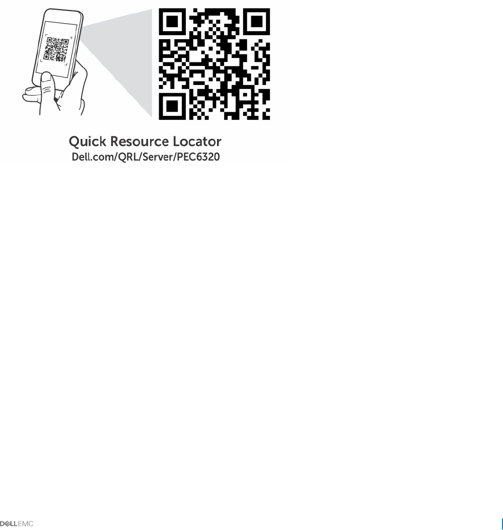
About this task
• How-to videos
• Reference materials, including the Owner’s Manual, LCD diagnostics, and mechanical overview
• Your system service tag to quickly access your specic hardware conguration and warranty information
• A direct link to Dell to contact technical assistance and sales teams
Steps
1 Go to Dell.com/QRL and navigate to your specic product or
2 Use your smartphone or tablet to scan the model-specic Quick Resource (QR) code on your Dell PowerEdge system or in the Quick
Resource Locator section.
Quick Resource Locator for C6320
Getting help 169
