Dell Storage Sc460 Expansion Enclosure Owner's Manual User En Us
User Manual: Dell storage-sc460 Dell SC460 Expansion Enclosure Owner's Manual
Open the PDF directly: View PDF ![]() .
.
Page Count: 65
- Dell SC460 Expansion Enclosure Owner's Manual
- About this Guide
- About the SC460 Expansion Enclosure
- SC460 Expansion Enclosure Installation
- Safety Precautions
- Unpacking Storage Center Equipment
- Determine the Mounting Location
- Install the Cable Management Tray
- Modify the Rail Lengths
- Install the Expansion Enclosure
- Install the Cable Management Arms
- Installing the Expansion Enclosure in a Non-Standard Rack
- Connect the Power Cables
- Install the Front Bezel
- Replacing SC460 Expansion Enclosure Components
- SC460 Expansion Enclosure Technical Specifications

Dell SC460 Expansion Enclosure
Owner's Manual
Regulatory Model: CYAE

Notes, Cautions, and Warnings
NOTE: A NOTE indicates important information that helps you make better use of your product.
CAUTION: A CAUTION indicates either potential damage to hardware or loss of data and tells you how to avoid the
problem.
WARNING: A WARNING indicates a potential for property damage, personal injury, or death.
Copyright © 2017 Dell Inc. or its subsidiaries. All rights reserved. Dell, EMC, and other trademarks are trademarks of Dell Inc. or its
subsidiaries. Other trademarks may be trademarks of their respective owners.
2017 - 11
Rev. B

Contents
About this Guide................................................................................................................ 5
Revision History..................................................................................................................................................................5
Audience............................................................................................................................................................................ 5
Contacting Dell...................................................................................................................................................................5
Related Publications........................................................................................................................................................... 5
1 About the SC460 Expansion Enclosure............................................................................7
SC460 Expansion Enclosure Overview............................................................................................................................... 7
SC460 Expansion Enclosure Front-Panel Features and Indicators...................................................................................... 7
SC460 Expansion Enclosure Back Panel Features and Indicators....................................................................................... 8
SC460 Expansion Enclosure Drives.................................................................................................................................... 8
SC460 Expansion Enclosure Drive Numbering....................................................................................................................9
2 SC460 Expansion Enclosure Installation......................................................................... 11
Safety Precautions.............................................................................................................................................................11
Installation Safety Precautions..................................................................................................................................... 11
Electrical Safety Precautions....................................................................................................................................... 11
Electrostatic Discharge Precautions............................................................................................................................ 12
General Safety Precautions.........................................................................................................................................12
Unpacking Storage Center Equipment.............................................................................................................................. 13
Determine the Mounting Location.....................................................................................................................................13
Install the Cable Management Tray................................................................................................................................... 14
Modify the Rail Lengths.................................................................................................................................................... 19
Install the Expansion Enclosure.........................................................................................................................................20
Install the Cable Management Arms................................................................................................................................. 23
Installing the Expansion Enclosure in a Non-Standard Rack..............................................................................................27
Install the Rails in a Nonstandard Rack....................................................................................................................... 27
Secure the Expansion Enclosure Chassis and Top Cover in a Nonstandard Rack....................................................... 29
Connect the Power Cables...............................................................................................................................................29
Install the Front Bezel.......................................................................................................................................................30
3 Replacing SC460 Expansion Enclosure Components.....................................................32
Safety Precautions........................................................................................................................................................... 32
Installation Safety Precautions....................................................................................................................................32
Bezel................................................................................................................................................................................ 33
Remove the Front Bezel.............................................................................................................................................33
Install the Front Bezel.................................................................................................................................................33
Pre-Replacement Procedures...........................................................................................................................................34
Send Diagnostic Data Using Dell SupportAssist..........................................................................................................34
Change the Operation Mode of the Storage Center to Maintenance......................................................................... 34
Shut Down the Storage System and Expansion Enclosures........................................................................................35
Hard Drives...................................................................................................................................................................... 35
Identifying the Failed Hard Drive.................................................................................................................................35
3

Remove a Hard Drive................................................................................................................................................. 36
Install a Hard Drive..................................................................................................................................................... 38
Cooling Fan Modules........................................................................................................................................................ 38
Identifying the Failed Cooling Fan Module.................................................................................................................. 39
Remove a Cooling Fan Module................................................................................................................................... 39
Install a Cooling Fan Module.......................................................................................................................................40
Enclosure Management Module........................................................................................................................................41
Identifying the Failed Enclosure Management Module................................................................................................ 41
Remove an Enclosure Management Module...............................................................................................................42
Install an Enclosure Management Module...................................................................................................................43
Power Supply Units.......................................................................................................................................................... 44
Identifying the Failed PSU.......................................................................................................................................... 44
Remove a PSU .......................................................................................................................................................... 45
Install a PSU .............................................................................................................................................................. 46
1U Cable Management Tray..............................................................................................................................................46
Remove the Cable Management Tray.........................................................................................................................46
Install the Cable Management Tray............................................................................................................................ 50
Cable Management Arms.................................................................................................................................................54
Remove the Cable Management Arms.......................................................................................................................55
Install the Cable Management Arms........................................................................................................................... 57
Expansion Enclosure Rack Rails........................................................................................................................................ 61
Remove the Expansion Enclosure Rails....................................................................................................................... 61
Install the Expansion Enclosure Rails.......................................................................................................................... 62
Post-Replacement Procedures.........................................................................................................................................63
Start Up the Storage System and Expansion Enclosure............................................................................................. 63
Send Diagnostic Data Using Dell SupportAssist..........................................................................................................63
Change the Operation Mode of the Storage Center to Normal.................................................................................. 63
4 SC460 Expansion Enclosure Technical Specications................................................... 64
Technical Specications................................................................................................................................................... 64
4

About this Guide
This guide describes how to perform service and maintenance on the SC460 expansion enclosure.
Revision History
Document Number: 680-140-001
Revision Date Description
A October 2017 Initial release
B November 2017 Change order of cable management tray installation
Audience
The information provided in this guide is intended for use by Dell end users.
Contacting Dell
Dell provides several online and telephone-based support and service options. Availability varies by country and product, and some
services might not be available in your area.
To contact Dell for sales, technical support, or customer service issues, go to www.dell.com/support.
• For customized support, type your system service tag on the support page and click Submit.
• For general support, browse the product list on the support page and select your product.
Related Publications
The following documentation is available for the SC460 expansion enclosure.
•Dell SC460 Expansion Enclosure Getting Started Guide
Provides information about an SC460 expansion enclosure, such as installation instructions and technical specications.
•Dell Storage Center Release Notes
Provides information about new features and known and resolved issues for the Storage Center software.
•Dell Storage Center Update Utility Administrator’s Guide
Describes how to use the Storage Center Update Utility to install Storage Center software updates. Updating Storage Center
software using the Storage Center Update Utility is intended for use only by sites that cannot update Storage Center using
standard methods.
•Dell Storage Center Software Update Guide
Describes how to update Storage Center software from an earlier version to the current version.
•Dell Storage Center Command Utility Reference Guide
Provides instructions for using the Storage Center Command Utility. The Command Utility provides a command-line interface
(CLI) to enable management of Storage Center functionality on Windows, Linux, Solaris, and AIX platforms.
•Dell Storage Center Command Set for Windows PowerShell
Provides instructions for getting started with Windows PowerShell cmdlets and scripting objects that interact with the Storage
Center using the PowerShell interactive shell, scripts, and PowerShell hosting applications. Help for individual cmdlets is available
online.
•Dell Storage Manager Administrator’s Guide
About this Guide 5

1
About the SC460 Expansion Enclosure
An SC460 expansion enclosure provides expansion storage for a Dell Storage Center.
The SC460 expansion enclosure connects directly to the SAS ports on the back of the storage system.
SC460 Expansion Enclosure Overview
The SC460 is a 4U SAS expansion enclosure that supports up to 60 3.5‐inch 12 Gbps hard drives.
The SC460 expansion enclosure ships with two redundant power supplies and two redundant enclosure management modules
(EMMs).
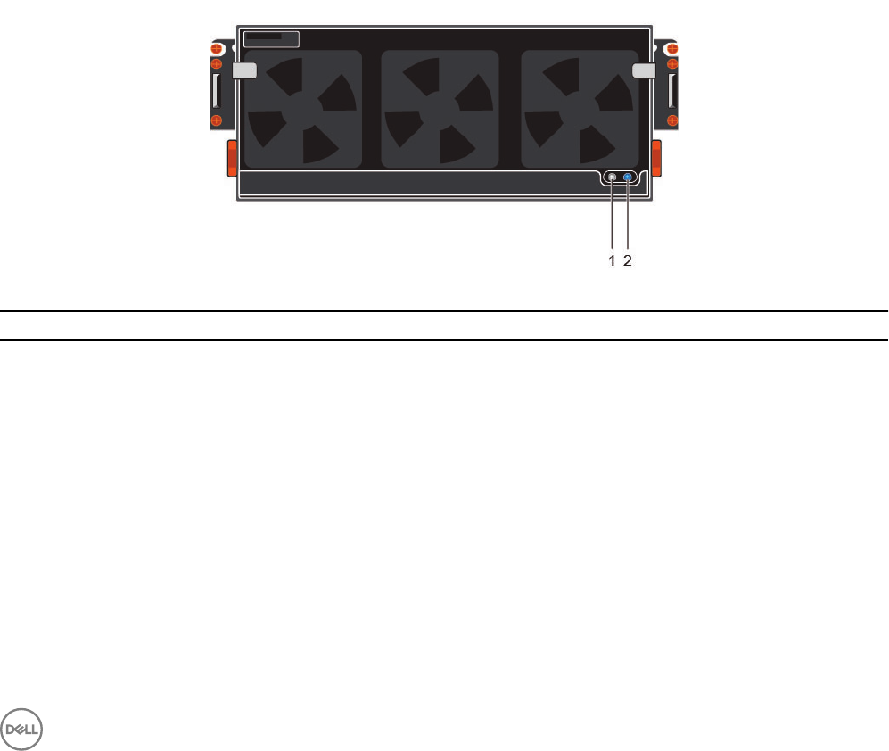
SC460 Expansion Enclosure Front-Panel Features and Indicators
The SC460 front panel shows the expansion enclosure status and power supply status.
Figure 1. SC460 Front-Panel Features and Indicators
Item Name Description
1 Power LED The power LED lights when at least one power supply unit is supplying power to the
expansion enclosure.
2 Expansion enclosure
status LED
The expansion enclosure status LED indicates when the system is being identied or when
the expansion enclosure is in the fault state.
•O during normal operation.
• Blinks blue when a host server is identifying the expansion enclosure or when the
system identication button is pressed.
• Remains solid blue when the expansion enclosure is in the fault state.
About the SC460 Expansion Enclosure 7
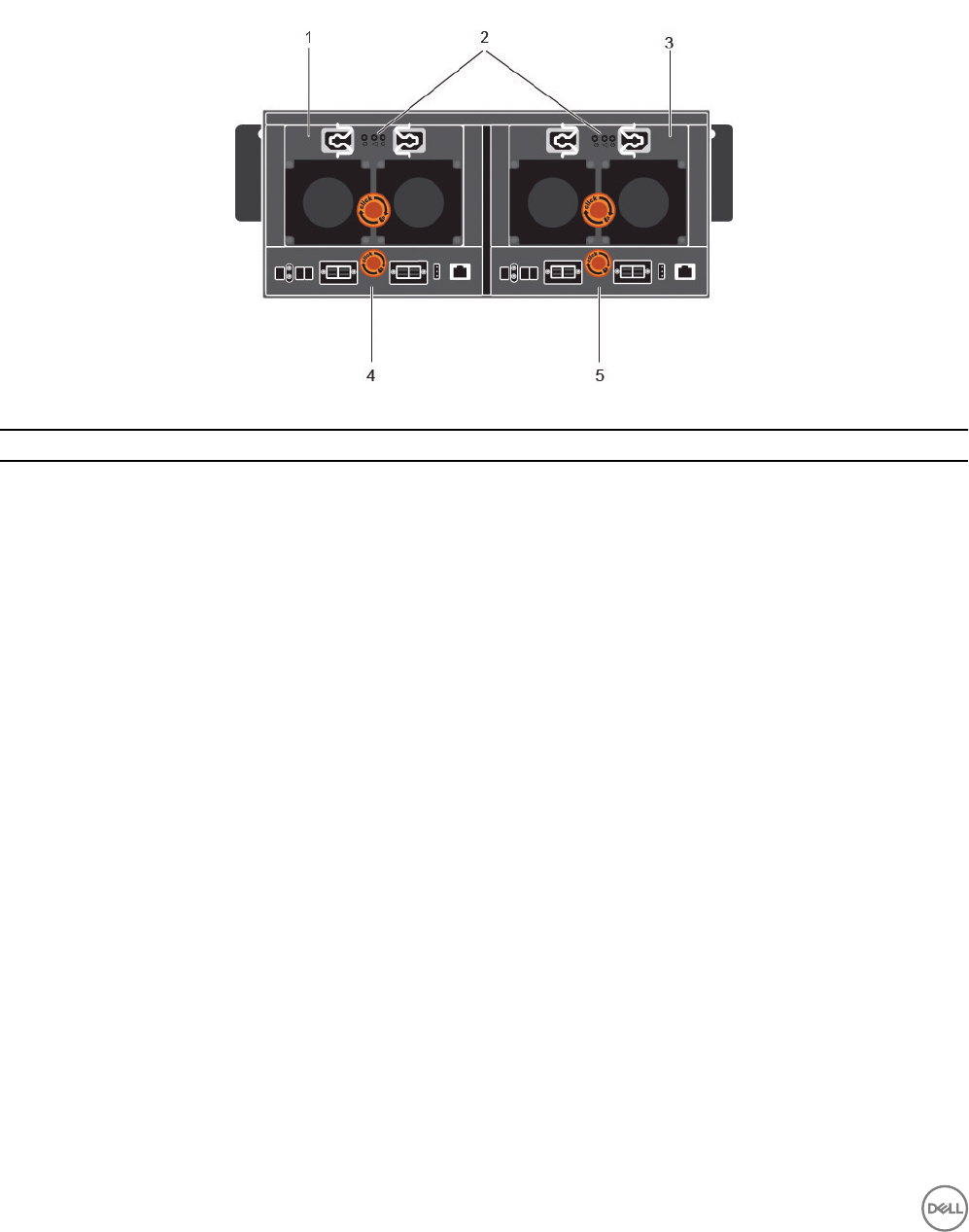
SC460 Expansion Enclosure Back Panel Features and Indicators
The SC460 back panel provides controls to power up and reset the expansion enclosure, indicators to show the expansion enclosure
status, and connections for back-end cabling.
Figure 2. SC460 Back Panel Features and Indicators
Item Name Description
1 Power supply unit and
cooling fan module (PS1)
Contains redundant 900 W power supplies and fans that provide cooling for the expansion
enclosure.
2 Power supply indicators
• AC power indicator
for power supply 1
• Power supply/cooling
fan indicator
• AC power indicator
for power supply 2
AC power indicators:
•Green: Normal operation. The power supply module is supplying AC power to the
expansion enclosure
•O: Power switch is o, the power supply is not connected to AC power, or has a fault
condition
•Flashing Green: AC power is applied but is out of spec.
Power supply/cooling fan indicator:
•Amber: Power supply/cooling fan fault is detected
•O: Normal operation
3 Power supply unit and
cooling fan module (PS2)
Contains redundant 900 W power supplies and fans that provide cooling for the expansion
enclosure.
4 Enclosure management
module 1
EMMs provide the data path and management functions for the expansion enclosure.
5 Enclosure management
module 2
EMMs provide the data path and management functions for the expansion enclosure.
SC460 Expansion Enclosure Drives
Dell Enterprise Plus drives are the only drives that can be installed in SC460 expansion enclosures. If a non-Dell Enterprise Plus drive
is installed, the Storage Center prevents the drive from being managed.
The drives in an SC460 expansion enclosure are installed horizontally.
8About the SC460 Expansion Enclosure
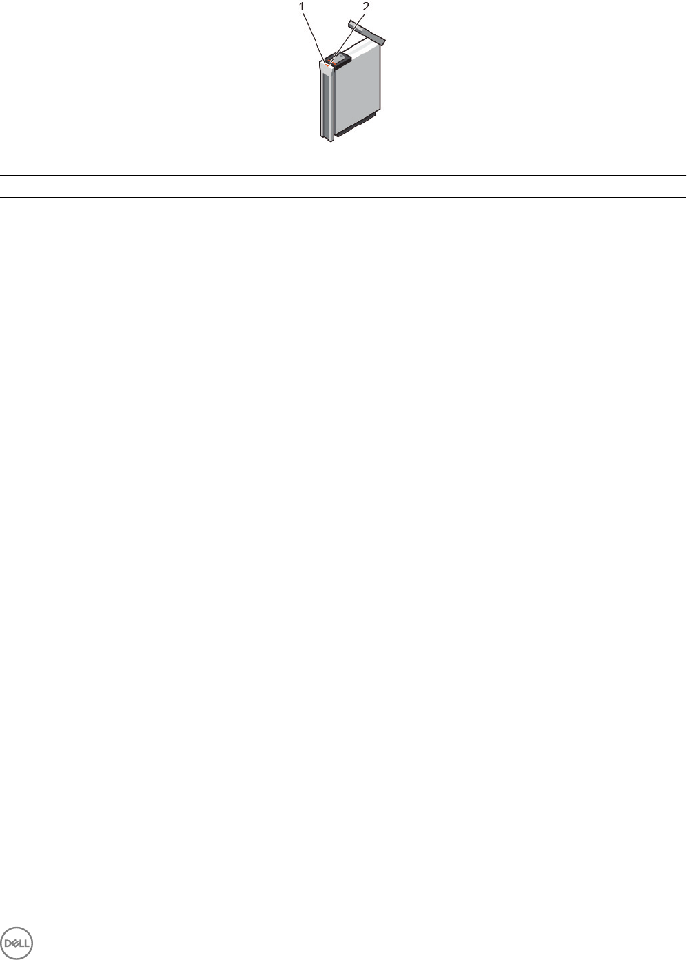
Figure 3. SC460 Drive Indicators
Item Name Indicator Code
1 Drive activity indicator • Blinking blue – Drive activity
• Steady blue – Drive is detected and has no faults
2 Drive status indicator •O – Normal operation
• Blinking amber (on 1 sec. / o 1 sec.) – Drive identication is enabled
• Steady amber – Drive has a fault
SC460 Expansion Enclosure Drive Numbering
The Storage Center identies drives as XX-YY, where XX is the unit ID of the expansion enclosure that contains the drive, and YY is
the drive position inside the expansion enclosure.
An SC460 holds up to 60 drives, which are numbered from left to right in rows starting from 0.
About the SC460 Expansion Enclosure 9
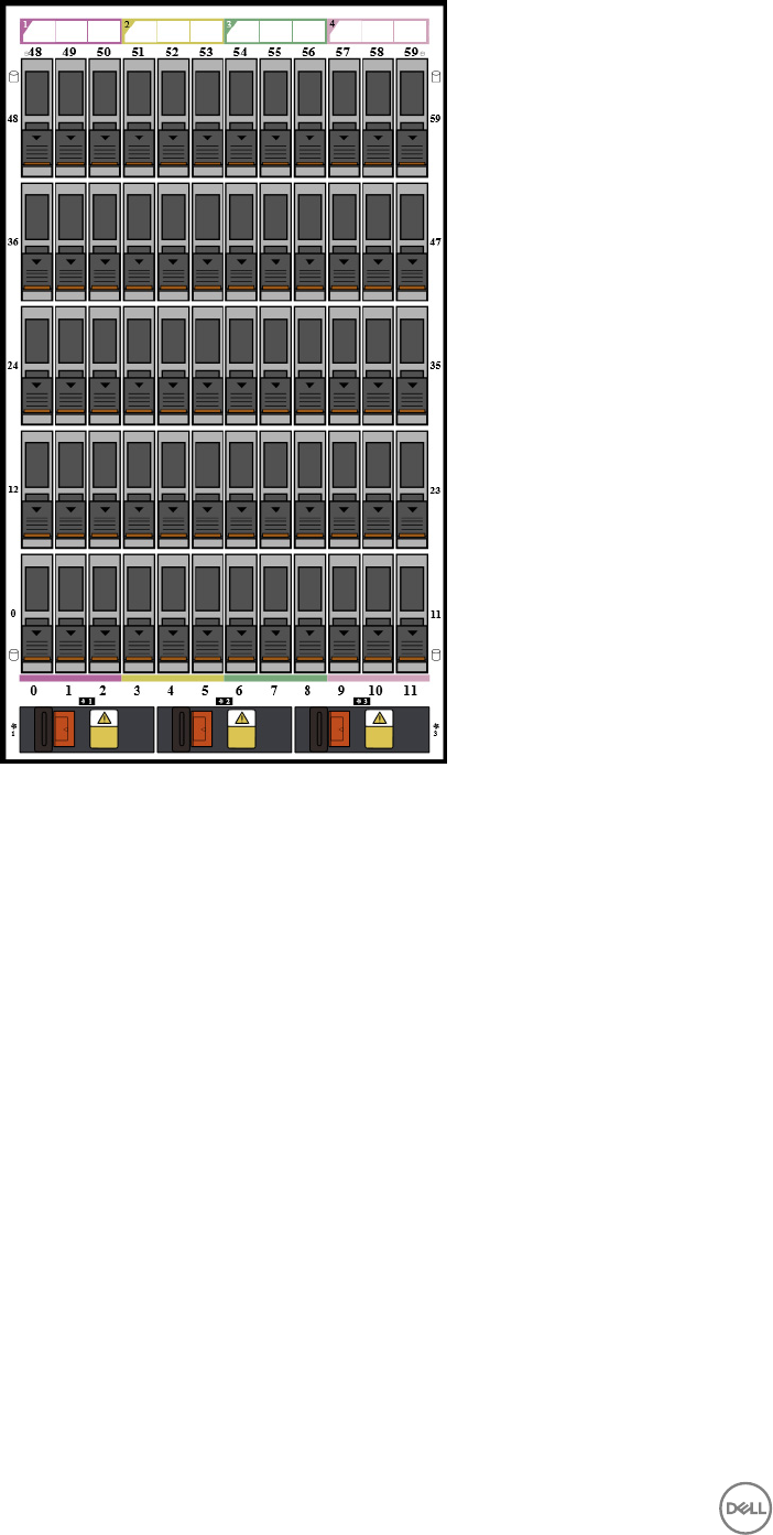
Figure 4. SC460 Drive Numbering
10 About the SC460 Expansion Enclosure
2
SC460 Expansion Enclosure Installation
This chapter describes how to install an SC460 expansion enclosure.
Safety Precautions
Always follow these safety precautions to avoid injury and damage to Storage Center equipment.
If equipment described in this guide is used in a manner not specied by Dell, the protection provided by the equipment could be
impaired. For your safety and protection, observe the rules described in the following sections.
NOTE: See the safety and regulatory information that shipped with each Storage Center component. Warranty
information is included as a separate document.
Installation Safety Precautions
Follow these safety precautions when installing an SC460 expansion enclosure:
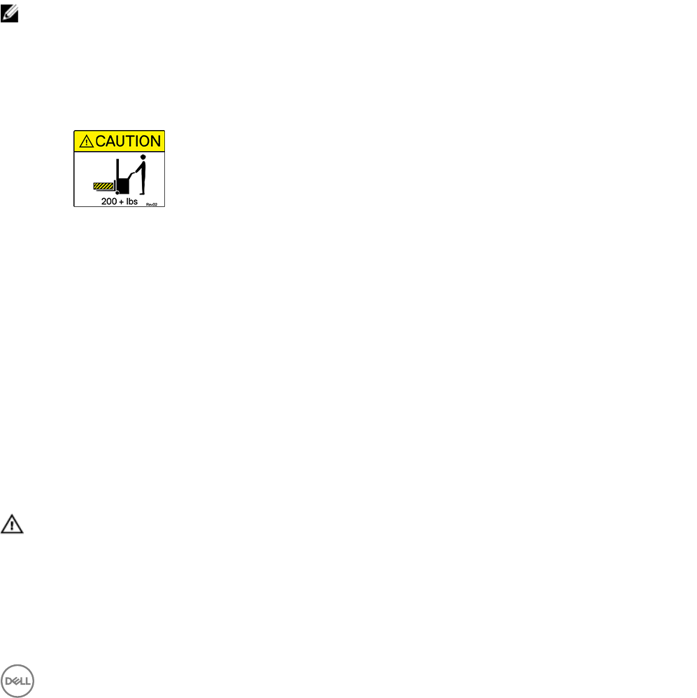
Caution
Equipment exceeds 90 kg (200 lb). Use appropriate lifting methods when installing an
SC460 expansion enclosure.
• You can install the expansion enclosure chassis without using a mechanical lift if you remove the drives, cooling fans, power
supply units (PSUs), and enclosure management modules (EMMs) from the chassis before installing it.
You must use a mechanical lift to install the expansion enclosure chassis if you do not remove the drives, cooling fans, PSUs, and
EMMs from the chassis.
• Dell recommends that only individuals with rack-mounting experience install an SC460 expansion enclosure in a rack.
• When installing multiple expansion enclosures in a rack, ll the rack from the bottom up and empty the rack from the top down.
• The rack construction must support the total weight of the installed expansion enclosures. The design should incorporate
stabilizing features suitable to prevent the rack from tipping or being pushed over during installation or in normal use.
• To prevent the rack from tipping, slide only one expansion enclosure out of the rack at a time.
• Make sure that the expansion enclosure is always fully grounded to prevent damage from electrostatic discharge.
• When handling the expansion enclosure components, use an electrostatic wrist guard or a similar form of protection.
Electrical Safety Precautions
Always follow electrical safety precautions to avoid injury and damage to Storage Center equipment.
WARNING: Disconnect power from the expansion enclosure when removing or installing components that are not hot-
swappable. When disconnecting power, rst power down the storage system using the storage client and then unplug
the power cords from the power supplies in the storage system and expansion enclosure.
• Provide a suitable power source with electrical overload protection. All Storage Center components must be grounded before
applying power. Make sure that a safe electrical earth connection can be made to power supply cords. Check the grounding
before applying power.
• The plugs on the power supply cords are used as the main disconnect device. Make sure that the socket outlets are located near
the equipment and are easily accessible.
SC460 Expansion Enclosure Installation 11

• Know the locations of the equipment power switches and the room's emergency power-o switch, disconnection switch, or
electrical outlet.
• Do not work alone when working with high-voltage components.
• Use rubber mats specically designed as electrical insulators.
• Do not remove covers from the power supply unit. Disconnect the power connection before removing a power supply from the
expansion enclosure.
• Do not remove a faulty power supply unless you have a replacement model of the correct type ready for insertion.
• Unplug the expansion enclosure chassis before you move it or if you think it has become damaged in any way. When powered by
multiple AC sources, disconnect all power sources for complete isolation.
Electrostatic Discharge Precautions
Always follow electrostatic discharge (ESD) precautions to avoid injury and damage to Storage Center equipment.
Electrostatic discharge (ESD) is generated by two objects with dierent electrical charges coming into contact with each other. The
resulting electrical discharge can damage electronic components and printed circuit boards. Follow these guidelines to protect your
equipment from ESD:
• Dell recommends that you always use a static mat and static strap while working on components in the interior of the chassis.
• Observe all conventional ESD precautions when handling plug-in modules and components.
• Use a suitable ESD wrist or ankle strap.
• Avoid contact with backplane components and module connectors.
• Keep all components and printed circuit boards (PCBs) in their antistatic bags until ready for use.
General Safety Precautions
Always follow general safety precautions to avoid injury and damage to Storage Center equipment.
• Keep the area around the expansion enclosure chassis clean and free of clutter.
• Place any system components that have been removed away from the expansion enclosure chassis or on a table so that they are
not in the way of other people.
• While working on the expansion enclosure chassis, do not wear loose clothing such as neckties and unbuttoned shirt sleeves.
These items can come into contact with electrical circuits or be pulled into a cooling fan.
• Remove any jewelry or metal objects from your body. These items are excellent metal conductors that can create short circuits
and harm you if they come into contact with printed circuit boards or areas where power is present.
• Do not lift the expansion enclosure chassis by the handles of the power supply units (PSUs). They are not designed to hold the
weight of the entire chassis, and the chassis cover could become bent.
• Before moving the expansion enclosure chassis, remove the PSUs to minimize weight.
• Do not remove drives until you are ready to replace them.
NOTE: To ensure proper expansion enclosure cooling, hard drive blanks must be installed in any hard drive slot that is not
occupied.
12 SC460 Expansion Enclosure Installation
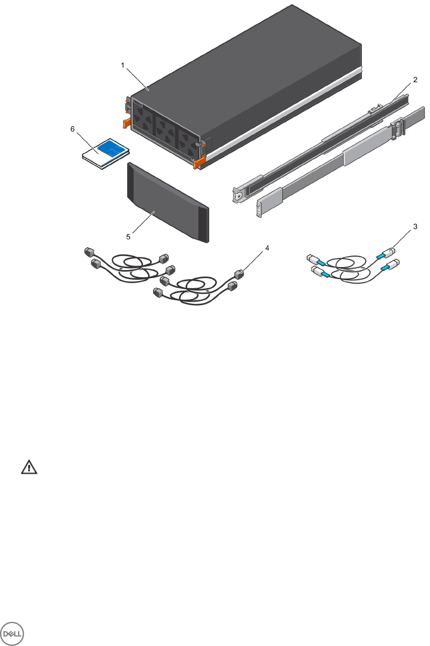
Unpacking Storage Center Equipment
Unpack the expansion enclosure and identify the items in your shipment.
Figure 5. Expansion Enclosure Components
1. Expansion enclosure 2. Rack rails (2)
3. Mini-SAS HD cables (2) 4. Power cables (4)
5. Front bezel (Optional) 6. Documentation
Determine the Mounting Location
Determine where to mount the SC460 expansion enclosure in the rack.
1. Identify a location in the rack with 4U of space for the expansion enclosure.
WARNING: If you plan to install the expansion enclosure above the lower 20U of a rack, use a mechanical lift to
avoid injury.
2. If you plan to install the 1U cable management tray below the expansion enclosure, identify a location in the rack with 5U of
space for the expansion enclosure and cable management tray.
SC460 Expansion Enclosure Installation 13
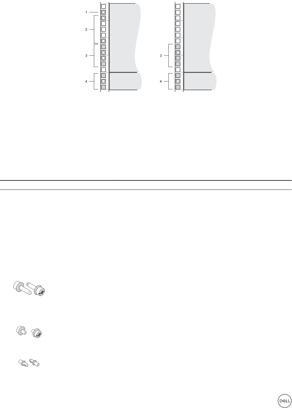
Figure 6. Mounting Location from Front and Back of Rack
1. Location for the clip nuts to secure the top cover 2. Location for the clip nuts to secure the expansion
enclosure
3. Location for the expansion enclosure rack rails 4. Location for the 1U cable management tray rails
Install the Cable Management Tray
If you plan to use the 1U cable management tray, install the tray before installing the SC460 expansion enclosure.
Prerequisite
Table 1. Identify the Hardware
Part Part Number Description
Screwdriver 034-000-193 6-in-1 screwdriver (Quantity: 1)
Left rail 042-034-012 Left rail for the cable management tray (Quantity: 1)
Right rail 042-034-008 Right rail for the cable management tray (Quantity: 1)
Cable management tray 042-033-060 1U cable management tray (Quantity: 1)
Cable management
chain 150-000-168 Chains for managing cables (Quantity: 2)
Chassis bracket 043-043-023 Bracket that secures the cable management chains to the chassis (Quantity:
1)
Front bezel 100-563-123 Bezel for the front of the cable management tray (Quantity: 1)
036-034-012
#8-32 x 3/4 in. Phillips screw (Quantity: 5)
Used to secure the cable management tray rails to a rack, regardless of the
rack type
Optional
036-034-003
Square hole alignment pin (Quantity: 9)
Replacement alignment pin used to mount tray rails in racks that have 0.375
in. square holes
036-034-004
Threaded hole alignment pin (Quantity: 9)
Replacement alignment pin used to mount tray rails in racks that have
threaded holes
14 SC460 Expansion Enclosure Installation
About this task
Install the 1U cable management tray into a rack with a depth of 1070 mm (42.1 in.).
Steps
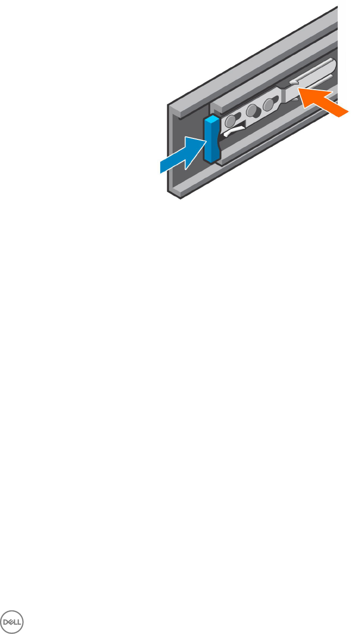
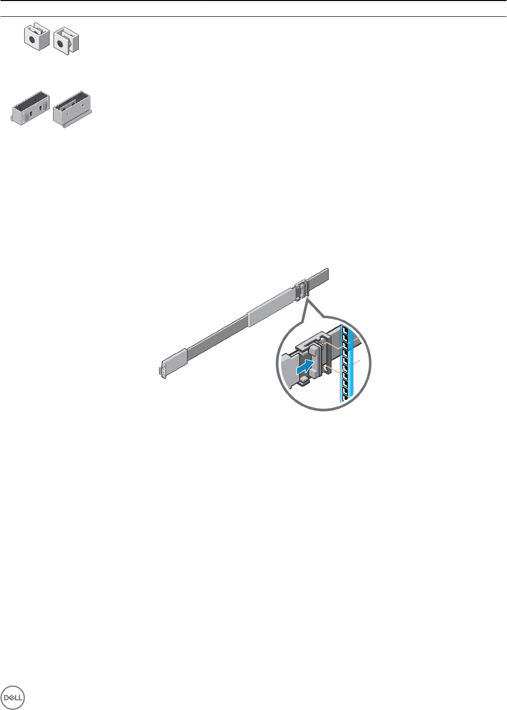
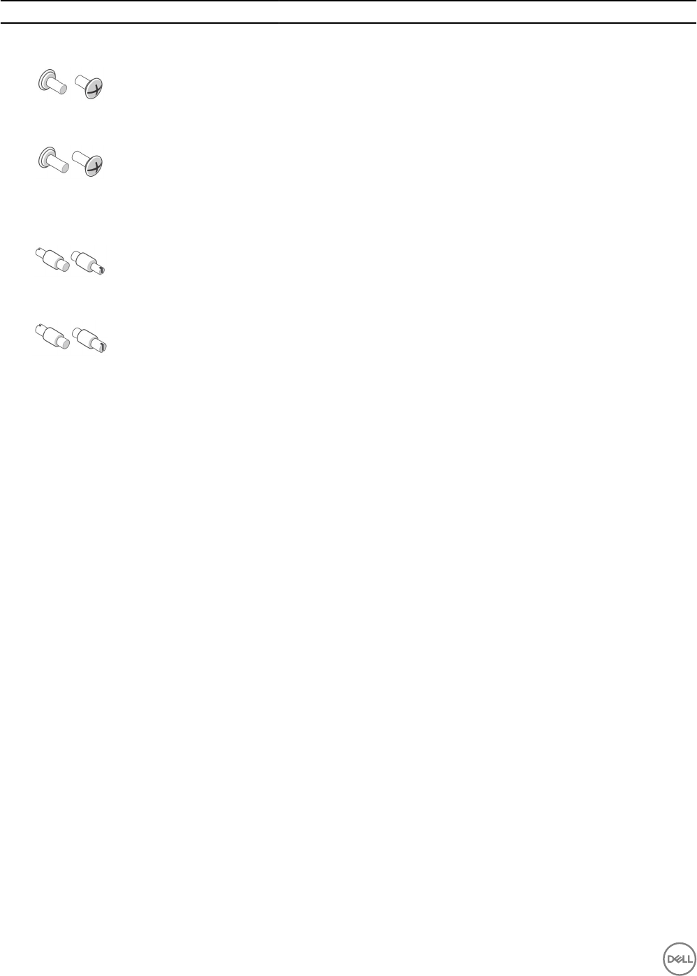
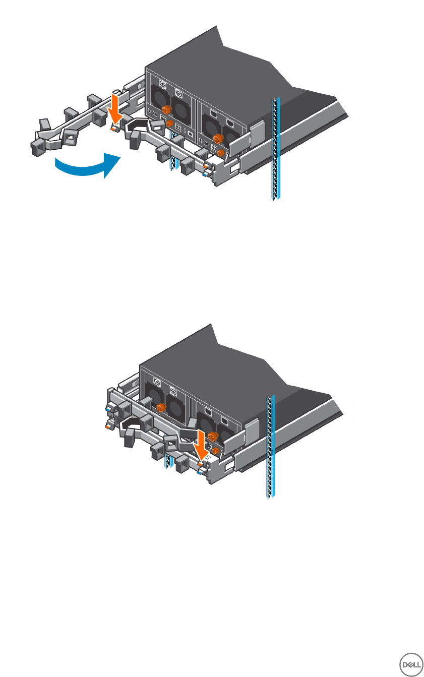
1. If the expansion enclosure rails are installed, push in on the blue tab of the rails before installing the 1U cable management tray.
Figure 7. Push in Blue Tab on Expansion Enclosure Rails
2. The 1U cable management tray rails are shipped with alignment pins that are designed to t into a standard Dell rack.
To install the rails in a nonstandard rack, remove the alignment pins from the rails and install the appropriate square hole or
threaded hole alignment pins.
a. Using a at-head screwdriver, remove the alignment pins from the front and back of the rails.
b. Identify the appropriate alignment pins (square hole or threaded hole) to use in the nonstandard rack
c. Install the appropriate alignment pins onto front and back of the rails.
3. Align the rails so that the UP arrow is pointed in the correct direction and the side of the rail labeled FRONT is at the front of
the rack.
4. Insert the alignment pins of left and right rails into the mounting holes at the front and back of the rack.
5. Secure the rails by installing 8-32 x 0.75 in. screws into the holes at the front and back of the rails.
SC460 Expansion Enclosure Installation 15
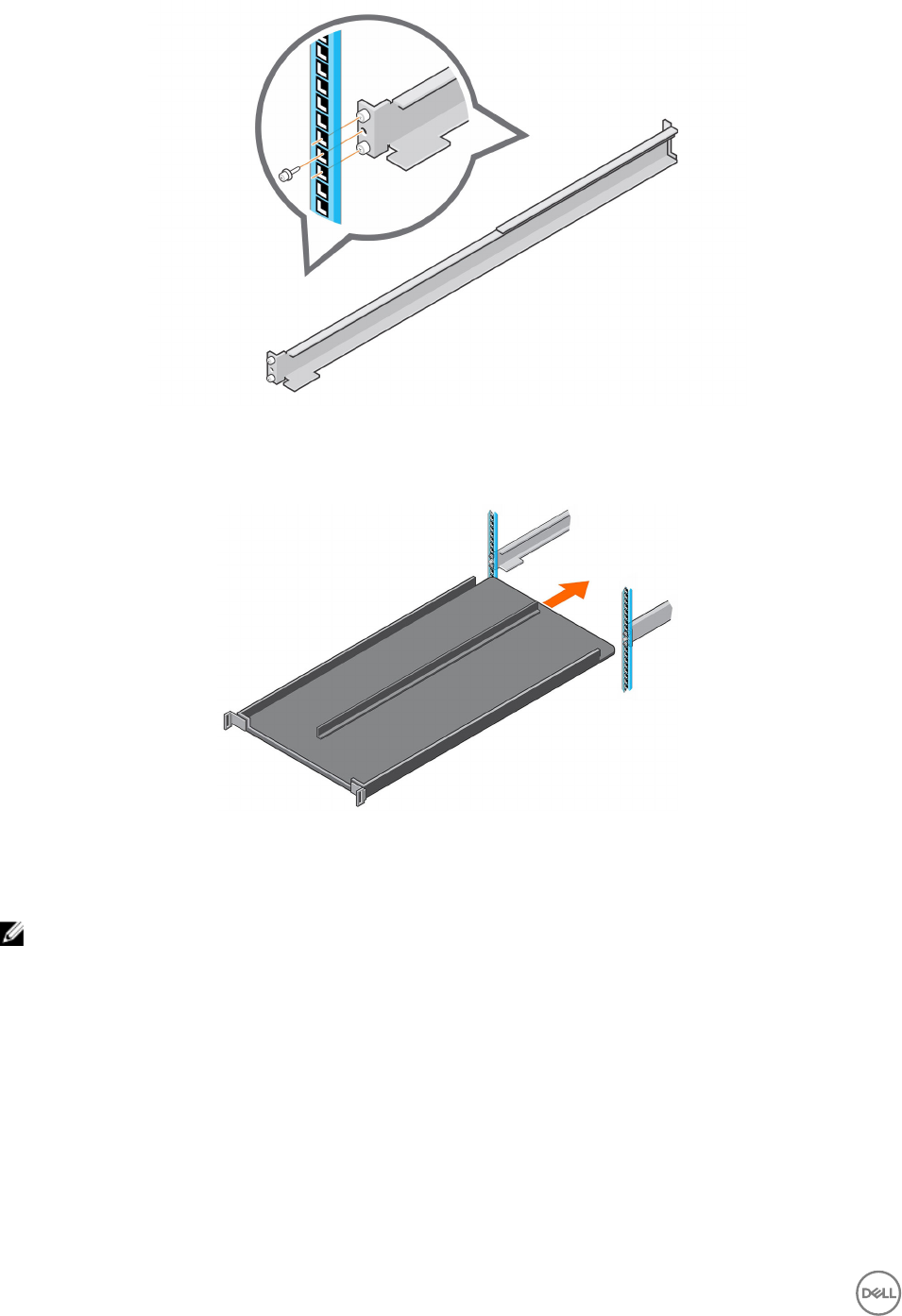
Figure 8. Secure Rails to Rack
6. Align the 1U cable management tray so that the UP arrow is pointed in the correct direction and the side of the tray labeled
FRONT is to the front of the rack.
Figure 9. Align the Cable Management Tray
7. Slide the 1U cable management tray into the rails until it locks into place.
8. Prepare the cable chains and route the cables through the cable chains.
NOTE: Label the cables before routing them through the cable chains.
a. Align the cable chains so the latches are facing up and the hinges are all facing each other.
b. Unclip and open the all of the latches on the cable chains.
16 SC460 Expansion Enclosure Installation
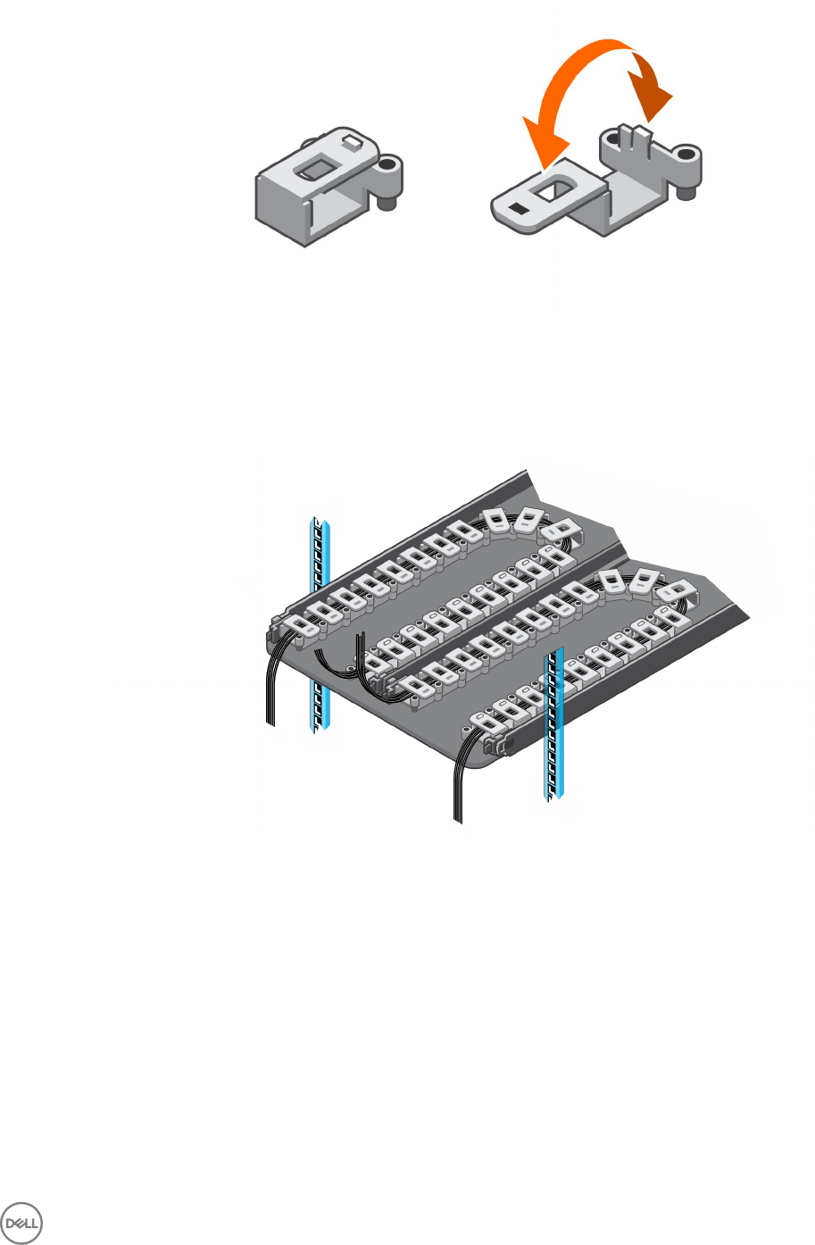
Figure 10. Open the Cable Chain Latches
c. Route two power cables and two Mini-SAS HD cables through each cable chain.
d. Close the latches and make sure that they are snapped shut.
e. Arrange the cable chains to form a "U" shape with the latches facing up.
f. Insert the cable chains through the back side of the tray.
Figure 11. Position the Cable Chains
9. Attach the clips on the cable chains to the tabs on the back of the 1U cable management rails.
SC460 Expansion Enclosure Installation 17
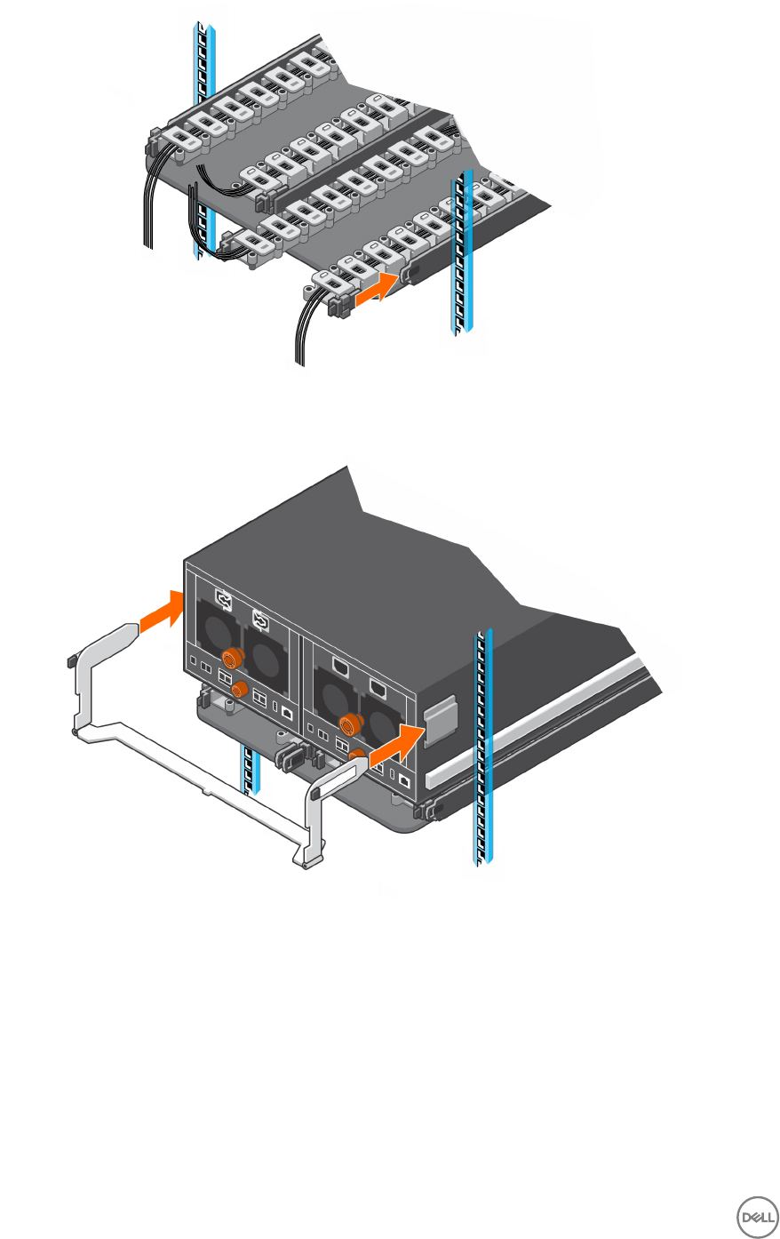
Figure 12. Attach Cable Chains to Tray Rails
10. Install the chassis bracket into the brackets on the side of the chassis.
Figure 13. Install the Chassis Bracket to the Chassis
11. Attach the clips on free end of the cable chains to the center ange on the chassis bracket.
18 SC460 Expansion Enclosure Installation
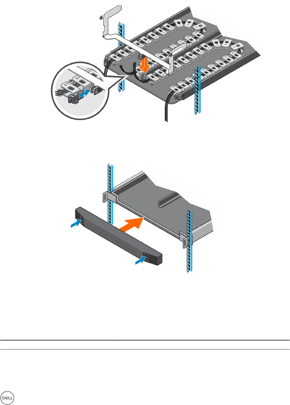
Figure 14. Clip Cable Chains to Chassis Bracket
12. Place the bezel over the front of the tray by pressing the release buttons on the bezel and placing it over the retaining slots on
the tray.
Figure 15. Install the Front Bezel
Modify the Rail Lengths
Use this procedure to extended or shorten the lengths of the expansion enclosure rails.
Prerequisite
Table 2. Identify the Hardware
Part Part Number Description
Left and right rails 100-569-001 Expansion enclosure rails (Quantity: 2)
Screwdriver 034-000-193 6-in-1 screwdriver (Quantity: 1)
10 mm socket or wrench N/A N/A
SC460 Expansion Enclosure Installation 19
About this task
The rails have four adjustment ranges: 18-22", 22-26", 26-30", 30-34". The default length of the rails is 22-26".
Steps
1. Orient one of the rails to display the spacing markings on the inside of the rail.
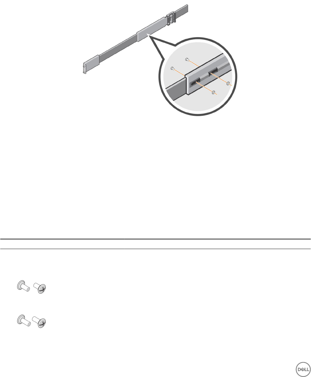
2. Locate the two screws and nuts which hold the length adjustment bracket in place.
3. Using a screwdriver and a 10 mm socket or wrench, remove both screws and nuts.
The length adjustment bracket will be free of the rail.
Figure 16. Remove Screws and Nuts
4. Move to the front of the rail and align the mounting slots with the mounting holes.
5. Slide the inner rail mechanism until the 18"-22", 26"-30", or 30"-34" mark is visible.
If the inner mechanism is locked, depress the leaf spring and press the rail locking mechanism to free it.
6. Adjust the hardware to make sure that the mounting holes are aligned with the mounting slots.
7. Secure the length adjustment bracket in place using both screws and nuts that were removed earlier.
8. Repeat the previous steps for the other rail.
Install the Expansion Enclosure
Install the rails in the rack, and mount the SC460 expansion enclosure on the rails.
Prerequisite
Table 3. Identify the Hardware
Part Part Number Description
Left and right rails 100-569-001 Expansion enclosure rails (Quantity: 2)
Screwdriver 034-000-193 6-in-1 screwdriver (Quantity: 1)
106-002-452
M5-0.8 x 10 mm Phillips pan-head SEMS screw (Quantity: 2)
Used to secure the expansion enclosure rails to the front of the rack
106-002-453
M5-0.8 x 16 mm Phillips pan-head SEMS screw (Quantity: 2)
Used to secure the expansion enclosure rails to the back of the rack
106-569-307 M5-0.8 clip nut (Quantity: 6)
20 SC460 Expansion Enclosure Installation
Part Part Number Description
Used to secure the expansion enclosure chassis and top cover to a rack
without threaded holes
036-034-003
Expansion enclosure chassis handle (Quantity: 4)
Used to lift the expansion enclosure chassis onto a mechanical lift and mount
it in a rack
Steps
1. Adjust the length of the expansion enclosure rails to t the rack.
2. Attach the right rail to the back post of the rack.
a. Align the right rail with the lower two U spaces of the 4U mounting location.
b. With the release latch on the outer part of the rack post, place the catch mechanism over the post.
c. Push the rail back to secure the rail to the rack post.
An audible click indicates that the rail is secure in the post.
d. Make sure the post/catch mechanism is secure and attached to the rack post.
Figure 17. Attach Rail to the Back of the Rack
3. Attach the right rail to the front post of the rack.
a. Align the right rail with the lower two U spaces of the 4U mounting location.
b. Pull the rail forward, with the alignment pins in the middle holes of the bottom two U spaces of the 4U mounting location.
An audible click indicates that the rail is secure in the post.
SC460 Expansion Enclosure Installation 21
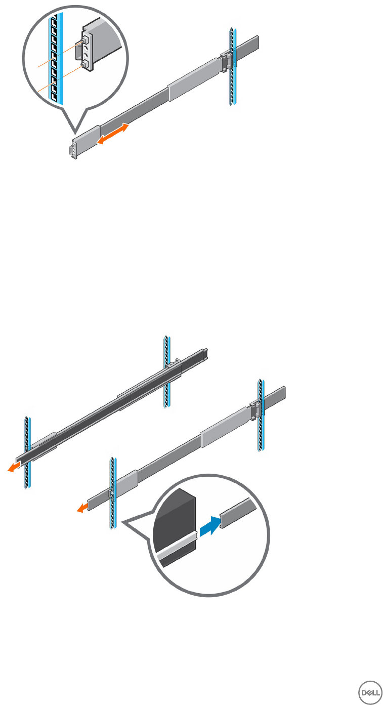
Figure 18. Attach Rail to the Front of the Rack
4. Secure the rail by installing an M5 x 10 mm screw in the larger of the two holes at the front of the rail.
5. Secure the rail by installing an M5 x 16 mm screw in the larger of the two holes at the back of the rail.
6. Repeat steps 2 through 5 to install the left rail.
7. Mount the expansion enclosure chassis on the rails.
a. If a mechanical lift is available, use the four handles that shipped with the expansion enclosure to lift the expansion
enclosure chassis onto a mechanical lift using the chassis handles.
b. If a mechanical lift is not available, remove the drives, cooling fans, power supply units (PSUs), and enclosure management
modules (EMMs) from the expansion enclosure chassis and lift the chassis to the mounting location using the chassis
handles.
c. From the front of the rack, extend the rails approximately 5 to 8 cm (2 to 3 in.) and align the expansion enclosure chassis
rails with the extended rails.
Figure 19. Extend the Rails from the Rack
d. Slide the extended rails over the expansion enclosure chassis rails.
e. Remove the four handles from the sides of the expansion enclosure chassis.
f. Slide the expansion enclosure chassis into the rack.
22 SC460 Expansion Enclosure Installation
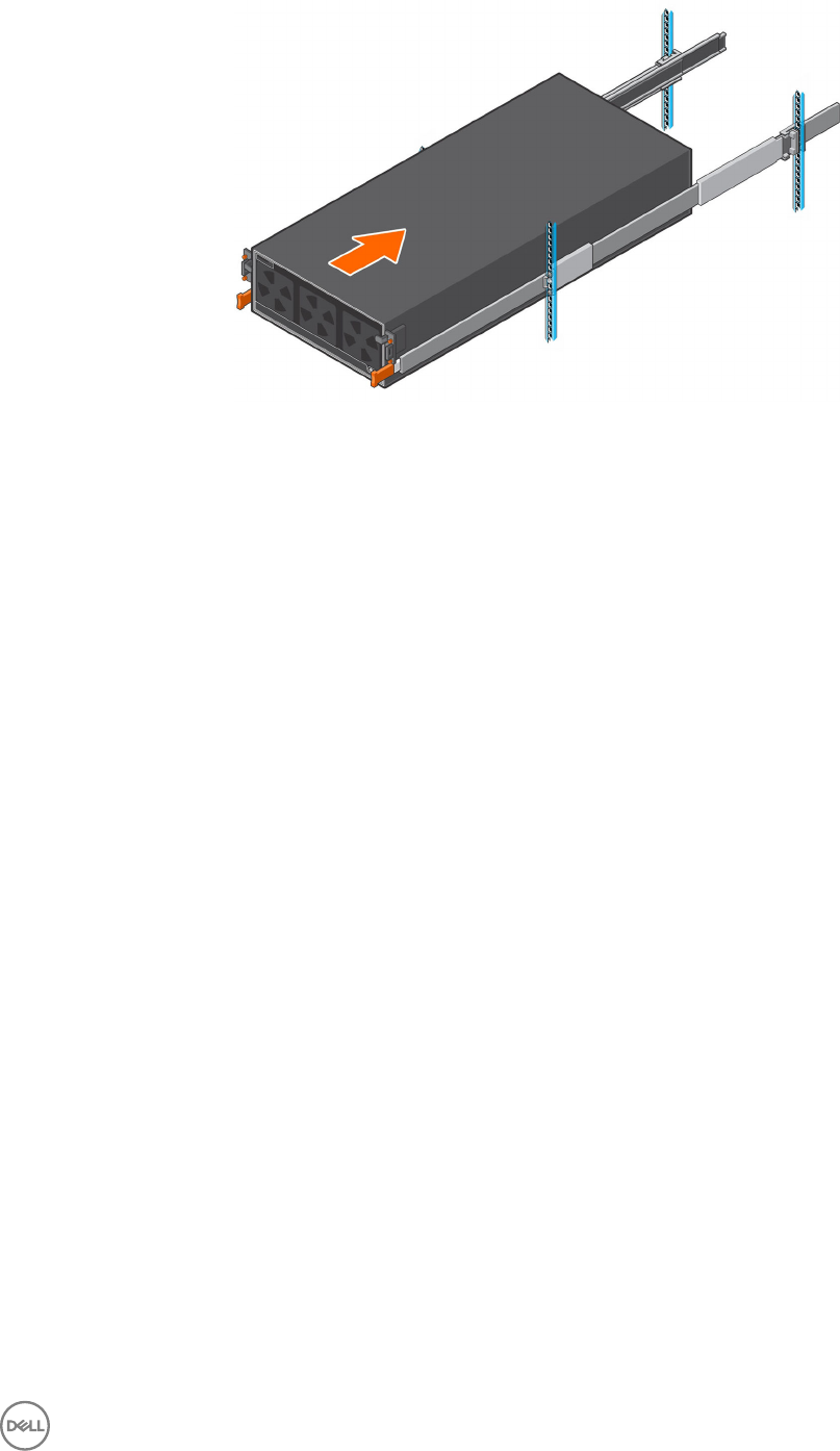
Figure 20. Mount the Expansion Enclosure into the Rack
8. If the drives, fans, PSUs, and EMMs were removed from the expansion enclosure chassis, reinstall these components in the
chassis.
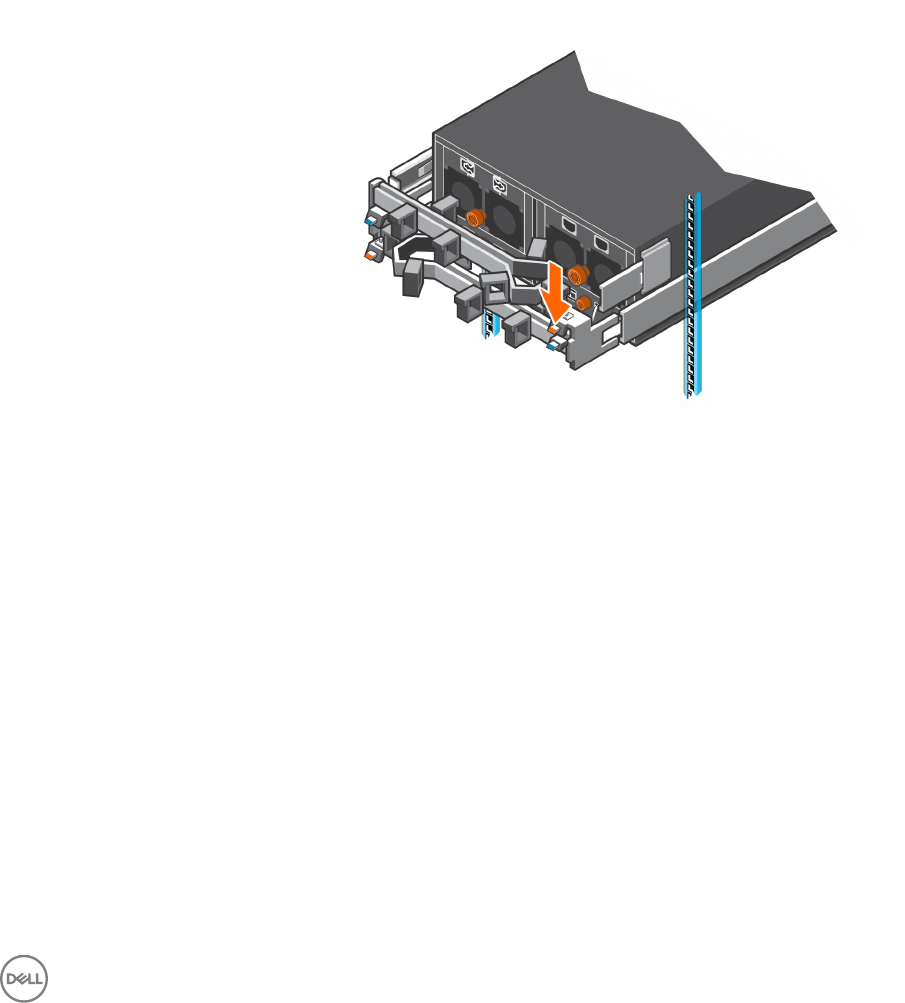
9. Secure the expansion enclosure chassis and top cover.
a. Install the six clip nuts into the rack holes that align with the shoulder screws on the front of the expansion enclosure
chassis.
b. Use the orange enclosure latch handles to push the expansion enclosure chassis completely into the rack.
Make sure that the self-locking latches are pushed in and fully engaged to prevent the expansion enclosure chassis from
sliding out of the rack.
c. Secure the expansion enclosure chassis to the rack using the orange shoulder screws.
d. If the top cover is secured by two small shipping screws, remove the screws.
e. Secure the top cover of the expansion enclosure chassis to the rack using the shoulder screws.
Install the Cable Management Arms
Installation of the cable management arms must be performed during a scheduled maintenance window when the Storage Center
system is unavailable to the network.
About this task
Install the cable management arms into a rack with a depth of 1200 mm (47.2 in.).
Steps
1. Align the retention latch end of the cable management arm with the enclosure bracket.
2. Insert the cable management arm into the enclosure bracket until you hear an audible click.
The audible click indicates that the cable management arm is secure.
SC460 Expansion Enclosure Installation 23
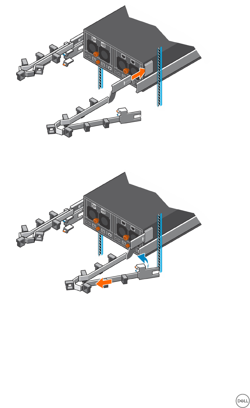
Figure 21. Installing Cable Management Arms
3. Swing the extension arm into alignment with the rail bracket.
Figure 22. Align Extension Arm with Rail Bracket
4. Push the extension arm into the rail bracket until you hear an audible click.
The audible click indicates that the cable management arm is secure.
24 SC460 Expansion Enclosure Installation

Figure 23. Insert Extension Arm into Rail Bracket
5. Repeat the previous steps for the second cable management arm.
6. Route the cables though the cable management arms.
NOTE: Label all the cables before routing them through the cable management arms.
a. Open the plastic brackets on the cable management arm.
b. Route the power cables and the Mini-SAS HD cables through the plastic brackets.
c. Close the plastic brackets on the cable management arm.
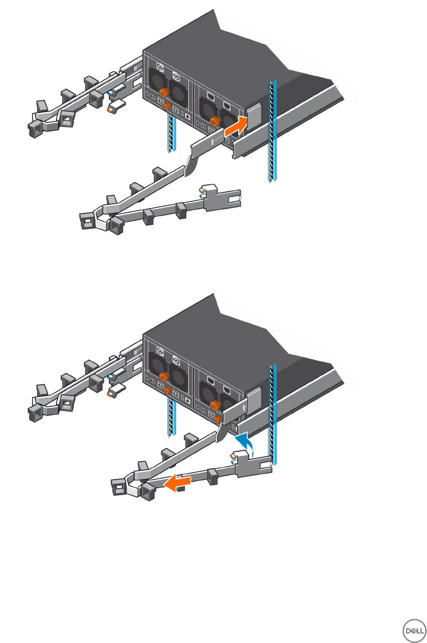
7. Close the cable management arms.
a. Swing the lower arm back and to the left side of the chassis.
Figure 24. Swing Lower Arm to Left Side of Chassis
b. Swing the upper arm back and to the right side of the chassis.
c. Align the securing tab on the right end of the lower arm with the notch over the orange release tab.
SC460 Expansion Enclosure Installation 25

d. Press the tab into the slot until you hear a click.
The click indicates that the arm is secure.
Figure 25. Swing Upper Arm to Right Side of Chassis and Secure Lower Arm
e. Align the securing tab on the left end of the upper arm with the notch over the orange release tab,
f. Press the tab into the slot until you hear a click.
The click indicates that the arm is secure.
Figure 26. Secure Cable Management Arm
8. Verify that the cable management arms are attached at the securing tabs.
26 SC460 Expansion Enclosure Installation
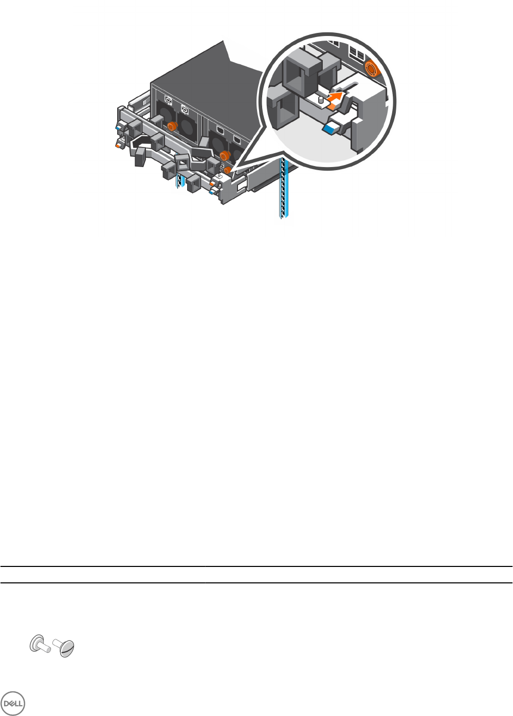
Figure 27. Verify that Cable Management Arms are Secure
9. Connect the power cables and the Mini-SAS HD cables to the expansion enclosure.
Next steps
1. Power on the expansion enclosure and storage system.
2. Use SupportAssist to send diagnostic data to Dell Technical Support.
Installing the Expansion Enclosure in a Non-Standard Rack
Follow these best practice guidelines when installing the SC460 expansion enclosure in a non-standard rack:
• A non-standard rack might have PDUs that face into the rack. This might cause interference between the expansion enclosure
and/or rear cable management arms (if used). Carefully plan and route cables to minimize any interference. It might be necessary
to use a dierent type of PDU that is mounted in the main rack area.
• The rack rails have four adjustment ranges, 18-22", 22-26", 26-30", 30-34". The default length is the 22-26" setting.
• After installing a rail, check the rail to make sure that it is level and in the correct location before installing the next rail.
• Use the M5 screws, which align with both round and square holes, to secure all rails and components in the rack.
• When securing rails to a rack, install the screws loosely to prevent cross threading, and tighten by hand. Do not over torque.
Install the Rails in a Nonstandard Rack
Perform the following steps to install the expansion enclosure rails in a nonstandard rack.
Prerequisite
Table 4. Identify the Hardware
Part Part Number Description
Screwdriver 034-000-193 6-in-1 screwdriver (Quantity: 1)
Left and right rack rails 100-569-001 Expansion enclosure rack rails (Quantity: 2)
036-028-018
M4-0.7 x 10 mm athead screw (Quantity: 4)
Used to secure expansion enclosure rails to a rack with threaded holes
SC460 Expansion Enclosure Installation 27
Part Part Number Description
or
106-002-452
M5-0.8 x 10 mm Phillips pan-head SEMS screw (Quantity: 2)
Used to secure the expansion enclosure rails to the front of the rack
106-002-453
M5-0.8 x 16 mm Phillips pan-head SEMS screw (Quantity: 2)
Used to secure the expansion enclosure rails to the back of the rack
Optional alignment pins
036-028-016
3.8 mm alignment pin (Quantity: 8)
Replacement alignment pin used to mount rails in racks that have M5, #10-32,
or #12-24 threaded holes
036-028-017
4.8 mm alignment pin (Quantity: 8)
Replacement alignment pin used to mount rails in racks that have M6
threaded holes
Steps
1. Determine where to mount the SC460 expansion enclosure in the rack.
2. Adjust the length of the expansion enclosure rack rails to t the rack.
3. The rails are shipped with 6.8 mm alignment pins that are designed to t into a standard Dell rack.
To install the rails in a nonstandard rack, remove the 6.8 mm alignment pins from the rails and install the appropriate optional
pins.
a. Using a at-head screwdriver, remove the 6.8 mm alignment pins from the front and back of the rails.
b. Identify the appropriate alignment pins (3.8 mm or 4.8 mm) to use in the nonstandard rack.
c. Install the appropriate alignment pins onto front and back of the rails.
4. Attach the right rail to the back post of the rack.
a. Align the right rail with the lower two U spaces of the 4U mounting location.
b. With the release latch on the outer part of the rack post, place the catch mechanism over the post.
c. Push the rail back to secure the rail to the rack post.
An audible click indicates that the rail is secure in the post.
d. Make sure the post/catch mechanism is secure and attached to the rack post.
5. Attach the right rail to the front post of the rack.
a. Align the right rail with the lower two U spaces of the 4U mounting location.
b. Pull the rail forward, with the alignment pins in the middle holes of the bottom two U spaces of the 4U mounting location.
An audible click indicates that the rail is secure in the post.
6. Secure the rail by installing screws at the front and back of the rack.
• If the rails are being installed in a rack that has threaded holes, insert M4-0.7 x 10 mm screws into the smaller of the two rail
screw holes at the front and back of the rack.
• If the rails are being installed in a rack that does not have threaded holes, insert M5-0.8 x 10 mm screws into the larger of
the two rail screw holes at the front of the rack. In addition, insert M5-0.8 x 16 mm screws into the larger of the two rail
screw holes at the back of the rack.
7. Repeat steps 4 through 6 to install the left rail.
28 SC460 Expansion Enclosure Installation
Secure the Expansion Enclosure Chassis and Top Cover in a Nonstandard Rack
Perform the following steps to secure the expansion enclosure in a rack that is not compatible with the semi-captive M5 shoulder
screws.
Prerequisite
Table 5. Identify the Hardware
Part Part Number Description
106-569-307
M5-0.8 clip nut (Quantity: 6)
Used to secure the expansion enclosure chassis and top cover to a rack
without threaded holes
036-032-010
M5-0.8 x 12 mm truss head Phillips screw with nylon patch (Quantity: 2)
Used to secure the expansion enclosure top cover to a rack with M5 threaded
holes or M5 clip nuts
036-032-011
M6-1.0 x 12 mm truss head Phillips screw with nylon patch (Quantity: 6)
Used to secure the expansion enclosure chassis and top cover to a
nonstandard rack with M6 threaded holes
036-032-009
#10-32 x 1/2 in. truss head Phillips screw with nylon patch (Quantity: 6)
Used to secure the expansion enclosure chassis and top cover to a
nonstandard rack with #10-32 threaded holes
036-032-012
#12-24 x 1/2 in. truss head Phillips screw with nylon patch (Quantity: 6)
Used to secure the expansion enclosure chassis and top cover to a
nonstandard rack with #12-24 threaded holes
Steps
1. Remove the semi-captive M5 shoulder screws from the expansion enclosure chassis and top cover.
2. In a rack with without threaded holes, place M5 clip nuts into the mounting holes on the rack that line up with the holes on the
expansion enclosure and top cover.
3. Secure the expansion enclosure and top cover to the rack using the appropriate truss head screws.
Connect the Power Cables
Connect the power cables to the SC460 expansion enclosure.
About this task
Steps
1. Connect the power cables to the power supplies in the expansion enclosure.
SC460 Expansion Enclosure Installation 29
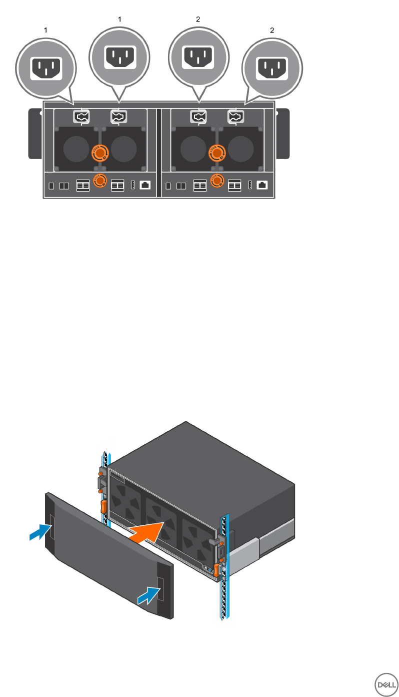
Figure 28. Connect Power Cables to the Power Supplies
1. Left power supply 2. Right power supply
2. Secure each power cable to the expansion enclosure using the strain relief clamp.
3. Connect the power cables plugged into the left power supply to one PDU.
4. Connect the power cables plugged into the right power supply to a second PDU.
5. Label both ends of the power cords to identify the power supply and PDU to which each power cord is connected.
Install the Front Bezel
If a front bezel is shipped with the SC460 expansion enclosure, install the bezel on the front of the expansion enclosure.
1. Align the bezel with the front of the expansion enclosure.
2. Press the two latches on front of bezel.
Figure 29. Install the Bezel
30 SC460 Expansion Enclosure Installation

3. Push the bezel into place until it attaches to the expansion enclosure.
4. Release the latches on the front on the bezel.
5. If the bezel has key lock, lock the bezel with the key.
SC460 Expansion Enclosure Installation 31
3
Replacing SC460 Expansion Enclosure
Components
This chapter describes how to replace eld replaceable units (FRUs) inside the SC460 expansion enclosure.
This chapter assumes that the installer has received the FRU and is ready to install it in the expansion enclosure.
Safety Precautions
Always follow these safety precautions to avoid injury and damage to Storage Center equipment.
If equipment described in this guide is used in a manner not specied by Dell, the protection provided by the equipment could be
impaired. For your safety and protection, observe the rules described in the following sections.
NOTE: See the safety and regulatory information that shipped with each Storage Center component. Warranty
information is included as a separate document.
Installation Safety Precautions
Follow these safety precautions when installing an SC460 expansion enclosure:
Caution
Equipment exceeds 90 kg (200 lb). Use appropriate lifting methods when installing an
SC460 expansion enclosure.
• You can install the expansion enclosure chassis without using a mechanical lift if you remove the drives, cooling fans, power
supply units (PSUs), and enclosure management modules (EMMs) from the chassis before installing it.
You must use a mechanical lift to install the expansion enclosure chassis if you do not remove the drives, cooling fans, PSUs, and
EMMs from the chassis.
• Dell recommends that only individuals with rack-mounting experience install an SC460 expansion enclosure in a rack.
• When installing multiple expansion enclosures in a rack, ll the rack from the bottom up and empty the rack from the top down.
• The rack construction must support the total weight of the installed expansion enclosures. The design should incorporate
stabilizing features suitable to prevent the rack from tipping or being pushed over during installation or in normal use.
• To prevent the rack from tipping, slide only one expansion enclosure out of the rack at a time.
• Make sure that the expansion enclosure is always fully grounded to prevent damage from electrostatic discharge.
• When handling the expansion enclosure components, use an electrostatic wrist guard or a similar form of protection.
32 Replacing SC460 Expansion Enclosure Components
Bezel
The front bezel is a cover for the front panel of the SC460 expansion enclosure.
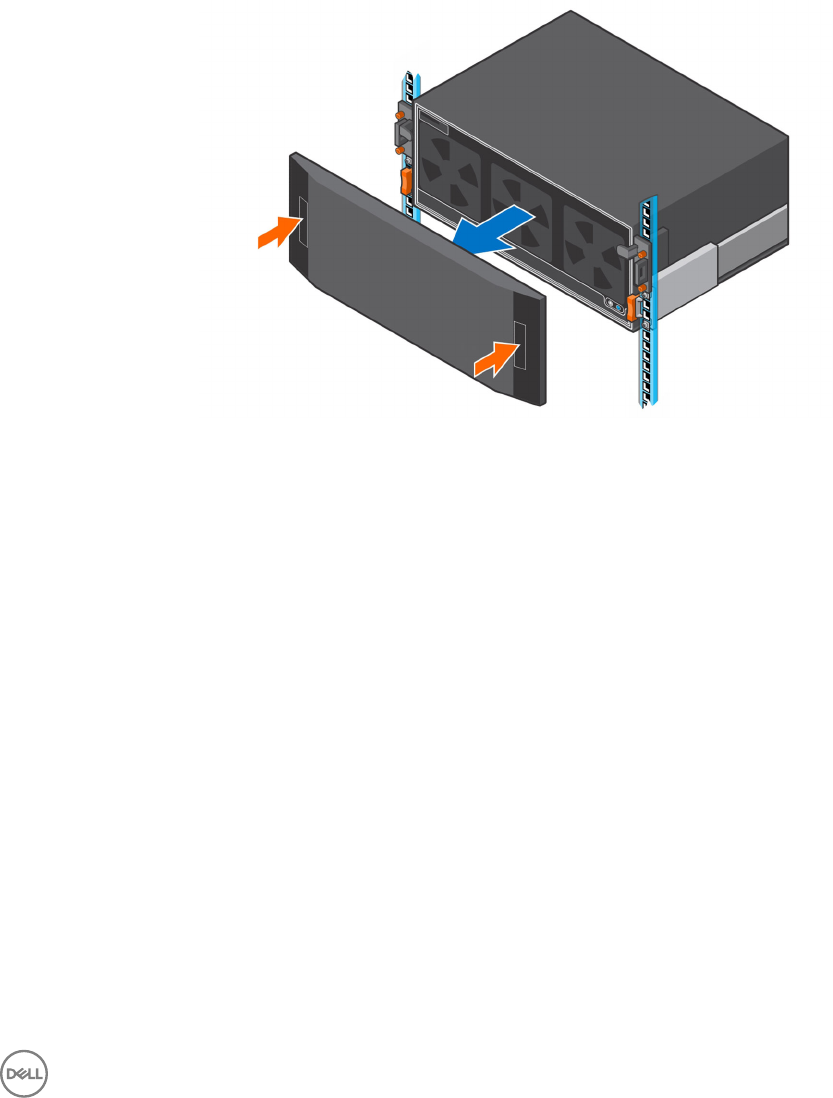
Remove the Front Bezel
Before you remove or install hard drives in the expansion enclosure, remove the front bezel.
1. If the bezel has key lock, unlock the bezel with the key.
2. Press the two latches on the front on the bezel.
3. Pull the bezel away from the expansion enclosure.
Figure 30. Remove the Bezel
Install the Front Bezel
If a front bezel is shipped with the SC460 expansion enclosure, install the bezel on the front of the expansion enclosure.
1. Align the bezel with the front of the expansion enclosure.
2. Press the two latches on front of bezel.
Replacing SC460 Expansion Enclosure Components 33
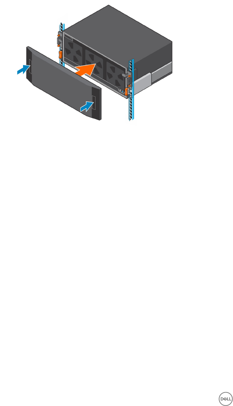
Figure 31. Install the Bezel
3. Push the bezel into place until it attaches to the expansion enclosure.
4. Release the latches on the front on the bezel.
5. If the bezel has key lock, lock the bezel with the key.
Pre-Replacement Procedures
Perform the procedures described in this chapter before replacing a component of the SC460 expansion enclosure.
Send Diagnostic Data Using Dell SupportAssist
Before replacing components, use Dell SupportAssist to send diagnostic data to Dell Technical Support.
1. Use Dell Storage Manager to connect to the Storage Center.
2. In the Summary tab, click Send SupportAssist Information Now, which is located under SupportAssist Actions in the Status
pane.
The Send SupportAssist Information Now dialog box opens.
3. Select Storage Center Conguration and Detailed Logs.
4. Click OK.
Change the Operation Mode of the Storage Center to Maintenance
Change the operation mode of the Storage Center to Maintenance before replacing components.
1. Use Dell Storage Manager to connect to the Storage Center.
2. In the Summary tab, click Edit Settings. The Edit Storage Center Settings dialog box opens.
3. Click the General tab.
4. In the Operation Mode eld select Maintenance. Selecting Maintenance isolates alerts from those that would occur during
normal operation.
5. Click OK.
34 Replacing SC460 Expansion Enclosure Components
Shut Down the Storage System and Expansion Enclosures
If the replacement component is not hot-swappable, use the Dell Storage Manager to shut down the storage system and expansion
enclosures. Shutting down the storage system and expansion enclosures results in a system outage, so plan to perform these
procedures during a maintenance window.
Prerequisites
Before shutting down the storage system and expansion enclosures, perform the following tasks:
1. Identify the part to replace.
2. Locate the replacement part.
3. Make sure that you have the tools required to replace the part.
Steps
1. From the Actions menu, select System→ Shutdown/Restart. The Shutdown/Restart dialog box appears.
2. From the What should the Storage Center do? drop-down menu, select Shut Down.
3. Click OK.
When the storage system and expansion enclosures are shut down, unplug the power cables from the storage system and
expansion enclosures.
Hard Drives
The SC460 expansion enclosure supports up to 60 3.5‐inch hot‐swappable hard drives installed in ve row by twelve column
conguration.
Identifying the Failed Hard Drive
To determine which hard drive failed, use Dell Storage Manager.
1. Click the Hardware tab.
2. In the Hardware tab navigation pane, select and expand the Storage Center.
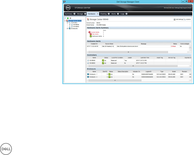
3. In the Hardware Alerts area, nd the hardware alert that identies the expansion enclosure with the failed hard drive.
Figure 32. Hardware Alert Identifying the Expansion Enclosure with the Failed Hard Drive
4. In the Hardware tab navigation pane, expand the expansion enclosure identied in the previous step.
5. Select Disks. The status of each disk is displayed in the Disks tab.
6. Select the failed hard drive.
The location of the failed hard drive is displayed in the Disk View tab.
Replacing SC460 Expansion Enclosure Components 35

Figure 33. Disk View Showing the Failed Hard Drive
Remove a Hard Drive
Use this procedure to remove a hard drive from the expansion enclosure.
Prerequisites
1. Use SupportAssist to send diagnostic data to Dell Technical Support.
2. Change the operation mode of the Storage Center to Maintenance.
About this task
You can remove a hard drive without shutting down the expansion enclosure.
CAUTION:
A drive must be replaced within 10 minutes of extending the expansion enclosure from the rack.
Steps
1. Remove the front bezel.
2. Extend the expansion enclosure chassis from the front of the rack.
3. To release the hard drive, push the orange release tab on the drive carrier towards the front of the expansion enclosure.
4. Lift the latch on the drive carrier and slowly pull the drive up approximately 3 cm (1 in.).
36 Replacing SC460 Expansion Enclosure Components
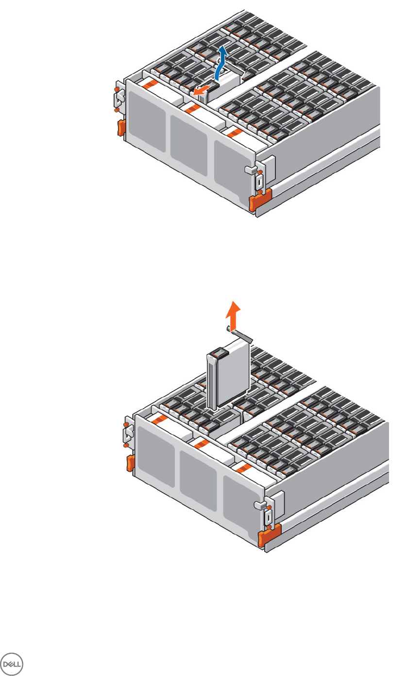
Figure 34. Releasing a Hard Drive
• If the drive fault LED is on, pull the drive up an additional 5 cm (2 in.). Wait 30 seconds for the drive to stop spinning and pull
the drive completely out of the slot.
• If the drive fault LED is o, pull the drive completely out of the slot.
Figure 35. Removing a Hard Drive
Replacing SC460 Expansion Enclosure Components 37
Install a Hard Drive
Use this procedure to install a hard drive in the expansion enclosure.
About this task
Do not drop the hard drive into the slot. Dropping the hard drive into the slot might damage the drive and the drive interface
backplane, which requires a full chassis replacement to repair.
CAUTION:
A drive must be replaced within 10 minutes of extending the expansion enclosure from the rack.
Steps
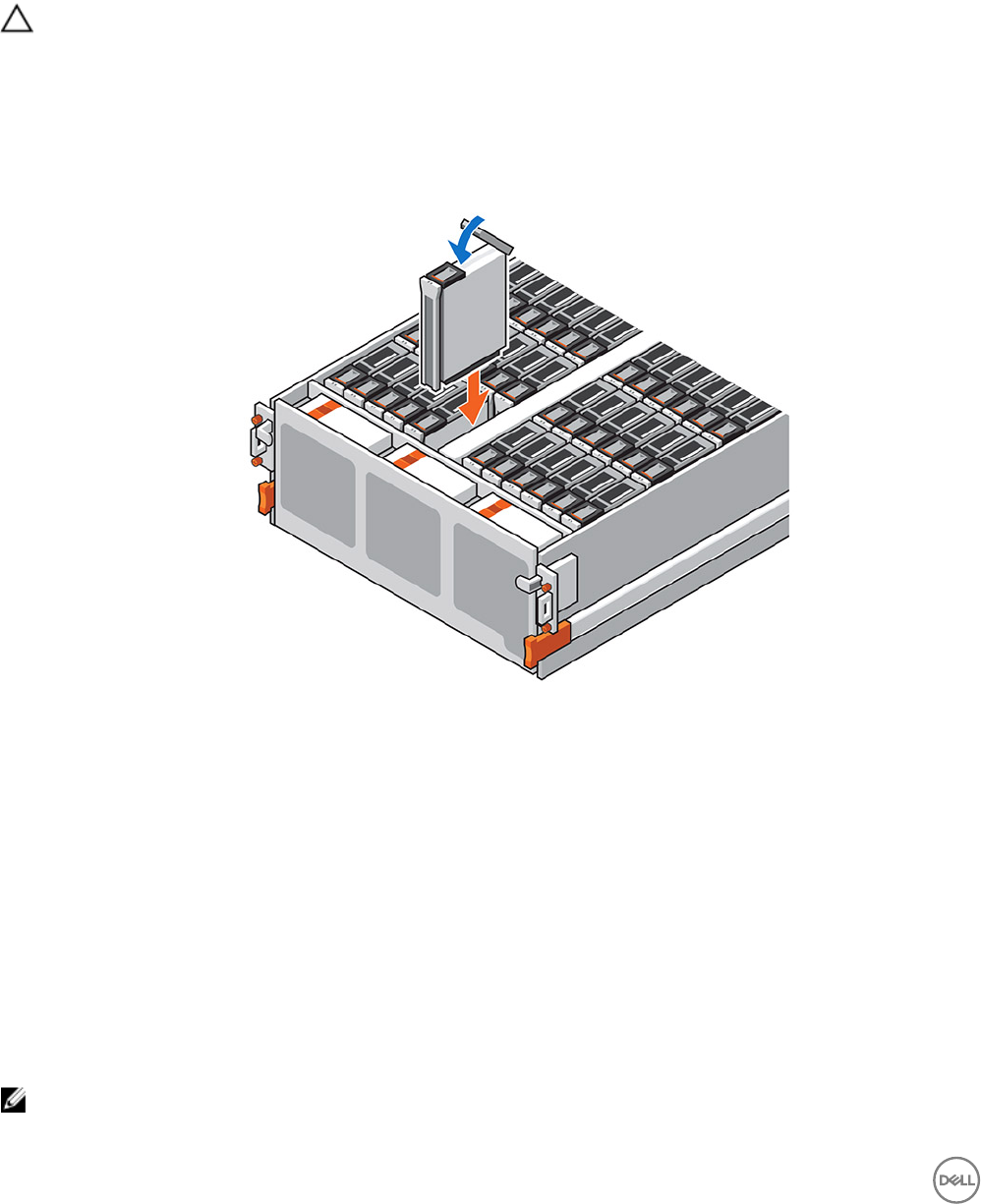
1. Open the latch on the drive carrier.
2. Align the drive with the guides and gently lower the disk into the slot.
The latch begins to close when the drive carrier meets the backplane.
3. Push down on the latch tab to engage the latch.
Figure 36. Installing a Hard Drive
4. When the latch is engaged, push on the drive carrier to verify that the drive is properly seated.
5. Wait for the expansion enclosure to recognize the hard drive and determine its status.
6. Push the expansion enclosure chassis back into the rack.
7. In Dell Storage Manager, make sure that the hard drive is recognized and shown as up and running.
Next steps
1. Use SupportAssist to send diagnostic data to Dell Technical Support.
2. Change the operation mode of the Storage Center to Normal.
Cooling Fan Modules
The SC460 expansion enclosure supports three cooling fan modules. If one cooling fan module fails, the remaining cooling fan
modules continue to cool the expansion enclosure.
NOTE: When a cooling fan module fails, the fan speed in the remaining modules increases signicantly to provide
adequate cooling. The cooling fan speed decreases gradually when a new cooling fan module is installed.
38 Replacing SC460 Expansion Enclosure Components
Identifying the Failed Cooling Fan Module
To determine which cooling fan module failed, use Dell Storage Manager.
1. Click the Hardware tab.
2. In the Hardware tab navigation pane, select and expand the Storage Center.
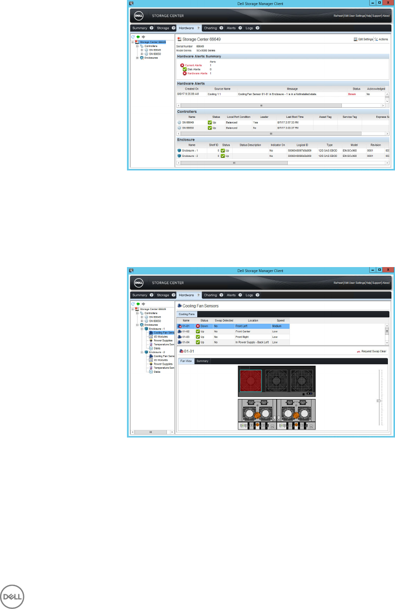
3. In the Hardware Alerts area, nd the hardware alert that identies the expansion enclosure with the failed cooling fan module.
Figure 37. Hardware Alert Identifying the Expansion Enclosure with the Failed Cooling Fan
4. In the Hardware tab navigation pane, expand the expansion enclosure identied in the previous step.
5. Select Cooling Fans.
The status of each cooling fan module is displayed in the Cooling Fans tab.
6. Select the failed cooling fan.
The location of the failed cooling fan module is displayed in the Fan View tab.
Figure 38. Rear View of the Expansion Enclosure Showing the Failed Cooling Fan Module
Remove a Cooling Fan Module
Use this procedure to remove a cooling fan module.
Prerequisites
1. Use SupportAssist to send diagnostic data to Dell Technical Support.
2. Change the operation mode of the Storage Center to Maintenance.
Replacing SC460 Expansion Enclosure Components 39
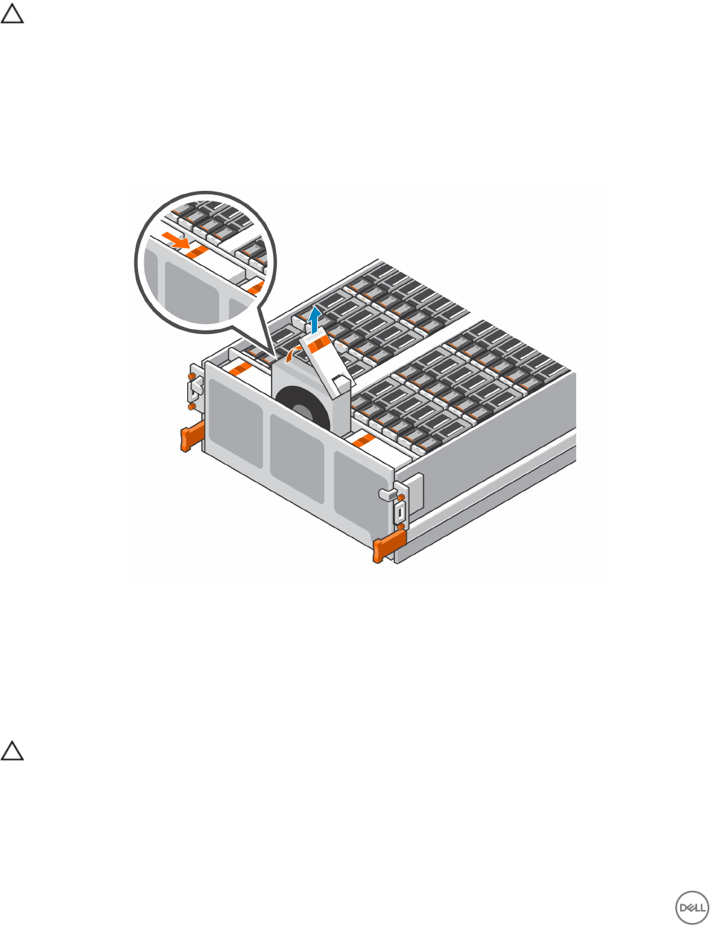
About this task
You can remove a cooling fan module without shutting down the expansion enclosure. However, the expansion enclosure must have
at least two cooling fan modules installed while the expansion enclosure is powered up. Do not remove more than one cooling fan
module while AC power is on.
CAUTION:
A cooling fan module must be replaced within ve minutes of extending the expansion enclosure from the rack. Do not remove
a faulted fan unless a replacement is on hand and available to be installed within ve minutes.
Steps
1. Remove the front bezel.
2. Extend the expansion enclosure chassis from the front of the rack.
3. Unlock the fan module by pushing the orange tab to the left.
4. Pull up on the latch handle to release the fan module.
5. Pull the fan module up and out of the chassis.
Figure 39. Removing a Cooling Fan Module
Install a Cooling Fan Module
Use this procedure to install a cooling fan module.
About this task
The expansion enclosure must have at least two cooling fan modules installed while the expansion enclosure is powered up. Do not
remove more than one cooling fan module while AC power is on.
CAUTION:
A cooling fan module must be replaced within ve minutes of extending the expansion enclosure from the rack. Do not remove
a faulted fan unless a replacement is on hand and available to be installed within ve minutes.
Steps
1. Align the cooling fan with the guides in the empty slot.
2. Gently lower the cooling fan into the empty slot.
3. Push the latch down into the closed position.
40 Replacing SC460 Expansion Enclosure Components
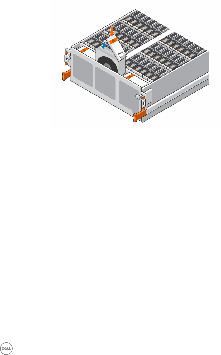
4. Push the black tab above the orange release tab down until you hear a click.
The click indicates that the fan is seated and secure in the slot.
Figure 40. Installing a Cooling Fan Module
5. Wait for the expansion enclosure to recognize the cooling fan module and determine its status.
6. Push the expansion enclosure chassis back into the rack.
7. In Dell Storage Manager, make sure that the cooling fan module is recognized and shown as up and running.
Next steps
1. Use SupportAssist to send diagnostic data to Dell Technical Support.
2. Change the operation mode of the Storage Center to Normal.
Enclosure Management Module
The SC460 expansion enclosure supports redundant hot-swappable enclosure management modules (EMMs).
EMMs provide the following management functions for the expansion enclosure:
• Monitoring and controlling expansion enclosure environment elements such as temperature, fan, power supplies, and expansion
enclosure LEDs
• Controlling access to hard drives
• Communicating expansion enclosure attributes and states to Storage Center
Identifying the Failed Enclosure Management Module
To determine which enclosure management module (EMM) failed, use the Dell Storage Manager.
1. Click the Hardware tab.
2. In the Hardware tab navigation pane, select and expand the Storage Center.
3. In the Hardware Alerts area, nd the hardware alert that identies the expansion enclosure with the failed EMM.
Replacing SC460 Expansion Enclosure Components 41
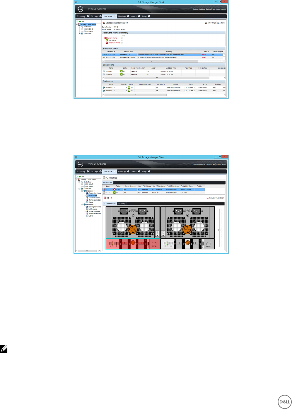
Figure 41. Hardware Alert Identifying the Expansion Enclosure with the Failed EMM
4. In the Hardware tab navigation pane, expand the expansion enclosure identied in the previous step.
5. Select I/O Modules.
The status of each EMM is displayed in the I/O Modules tab.
6. Select the failed EMM.
The location of the failed EMM is displayed in the I/O Module View tab.
Figure 42. Rear View of the Expansion Enclosure Showing the Failed EMM
Remove an Enclosure Management Module
Use this procedure to replace a EMM.
Prerequisites
1. Use SupportAssist to send diagnostic data to Dell Technical Support.
2. Change the operation mode of the Storage Center to Maintenance.
About this task
EMMs can be replaced one at a time without shutting down the expansion enclosure.
NOTE: Make sure the SAS cables are labeled before disconnecting the cables from the EMM.
Steps
1. If the expansion enclosure is installed with cable management arms (CMAs), open the CMAs.
2. Disconnect the SAS cables connected to the EMM.
3. Turn the screw handle counter-clockwise until the EMM is unseated from the chassis.
42 Replacing SC460 Expansion Enclosure Components
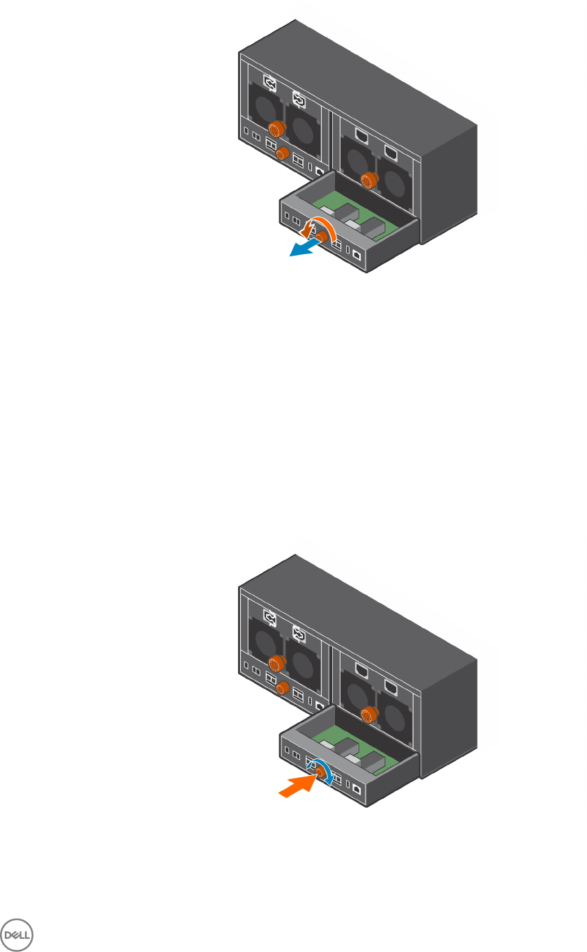
4. Slide the EMM out of the chassis and place it on a clean, static-free surface.
Figure 43. Removing an EMM
Install an Enclosure Management Module
Use this procedure to install an EMM.
About this task
EMMs can be replaced one at a time without shutting down the expansion enclosure.
Steps
1. Align the EMM with the empty slot in the chassis.
2. Push the EMM into the chassis until it stops.
3. Turn the screw handle clockwise until a single click is heard.
The single click indicates the EMM is fully seated.
Figure 44. Installing an EMM
4. Match the labels on the SAS cables with the correct connectors on the EMM.
5. Reconnect the SAS cables to the EMM.
Replacing SC460 Expansion Enclosure Components 43
6. Wait for the expansion enclosure to recognize the EMM and determine its status.
7. In Dell Storage Manager, make sure that the EMM is recognized and shown as up and running.
Next steps
1. Use SupportAssist to send diagnostic data to Dell Technical Support.
2. Change the operation mode of the Storage Center to Normal.
Power Supply Units
The SC460 expansion enclosure supports two hot-swappable power supply units (PSUs). If one unit fails, the second unit continues
to provide power to the expansion enclosure.
Identifying the Failed PSU
To determine which power supply unit (PSU) failed, use the Dell Storage Manager.
1. Click the Hardware tab.
2. In the Hardware tab navigation pane, select and expand the Storage Center.
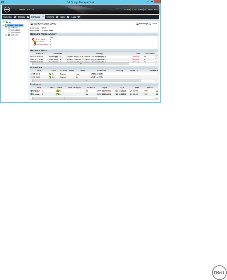
3. In the Hardware Alerts area, nd the hardware alert that identies the expansion enclosure with the failed power supply.
Figure 45. Hardware Alert Identifying the Expansion Enclosure with the Failed Power Supply
4. In the Hardware tab navigation pane, expand the expansion enclosure identied in the previous step.
5. Select Power Supplies.
The status of each power supply is displayed in the Power Supplies tab.
6. Select the failed power supply.
The location of the failed power supply is displayed in the Power Supply View tab.
44 Replacing SC460 Expansion Enclosure Components
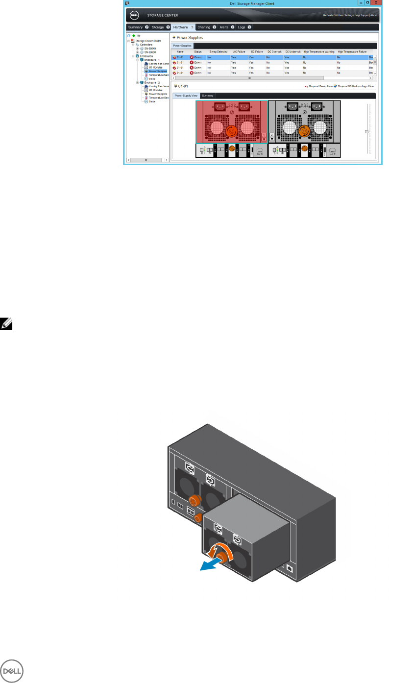
Figure 46. Rear View of the Expansion Enclosure Showing the Failed the Power Supply
Remove a PSU
Use this procedure to remove a power supply unit (PSU) from the expansion enclosure.
Prerequisites
1. Use SupportAssist to send diagnostic data to Dell Technical Support.
2. Change the operation mode of the Storage Center to Maintenance.
About this task
You can remove a single PSU without shutting down the expansion enclosure.
NOTE: Make sure the power cables are labeled before disconnecting them from the PSU.
Steps
1. If the expansion enclosure is installed with cable management arms (CMAs), open the CMAs.
2. Remove the strain relief clamps from the power cables and disconnect the power cables from the PSU.
3. Turn the screw handle counter-clockwise until the PSU is unseated from the chassis.
4. Slide the PSU out from the chassis and place it on a clean, static-free surface.
Figure 47. Removing a PSU
Replacing SC460 Expansion Enclosure Components 45
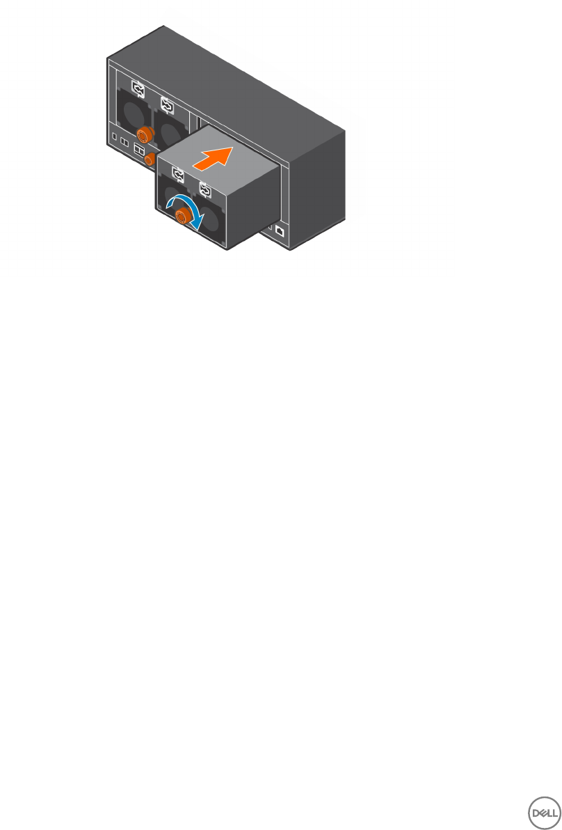
Install a PSU
Use this procedure to install a power supply unit (PSU) in the expansion enclosure.
Steps
1. Slide the replacement PSU into the expansion enclosure chassis.
2. Turn the screw handle clockwise until a single click is heard.
The single click indicates the PSU is fully seated.
Figure 48. Installing a PSU
3. Match the labels on the power cables with the correct power connectors on the PSU.
4. Reconnect the power cables to the PSU and secure the power cables using the strain relief clamps.
5. Wait for the expansion enclosure to recognize the PSU and determine its status.
6. In Dell Storage Manager, make sure that the PSU is recognized and shown as up and running.
Next steps
1. Use SupportAssist to send diagnostic data to Dell Technical Support.
2. Change the operation mode of the Storage Center to Normal.
1U Cable Management Tray
The SC460 expansion enclosure supports a 1U cable management tray.
If you plan to use the 1U cable management tray, install the tray before installing the expansion enclosure. The 1U cable management
tray is installed in the 1U space below the expansion enclosure.
Remove the Cable Management Tray
Removal of the 1U cable management tray must be performed during a scheduled maintenance window when the Storage Center
system is unavailable to the network.
Prerequisites
1. Use SupportAssist to send diagnostic data to Dell Technical Support.
2. Change the operation mode of the Storage Center to Maintenance.
3. Use Dell Storage Manager to shut down the storage system connected to the expansion enclosure.
46 Replacing SC460 Expansion Enclosure Components
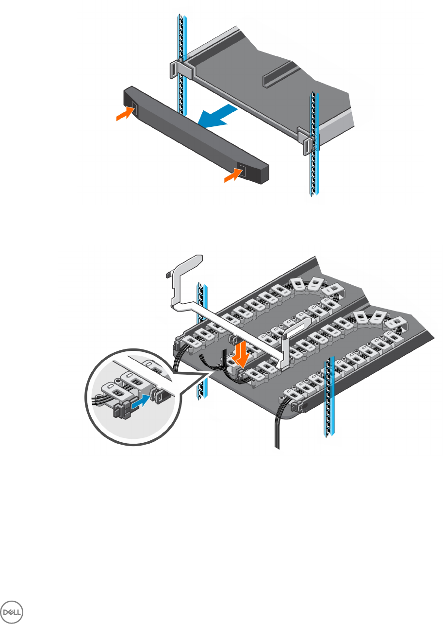
Steps
1. Make sure all the cables are labeled.
2. Disconnect the power cables and Mini-SAS HD cables from the expansion enclosure.
3. Remove the bezel from the front of the tray.
Figure 49. Remove the Front Bezel
4. Press the tabs on the inner cable chains to disconnect the cable guide clips from the chassis bracket.
Figure 50. Disconnect Cable Chains from the Chassis Bracket
5. Press the tabs on the outer cable chains to disconnect the cable guide clips from the 1U cable management tray.
Replacing SC460 Expansion Enclosure Components 47
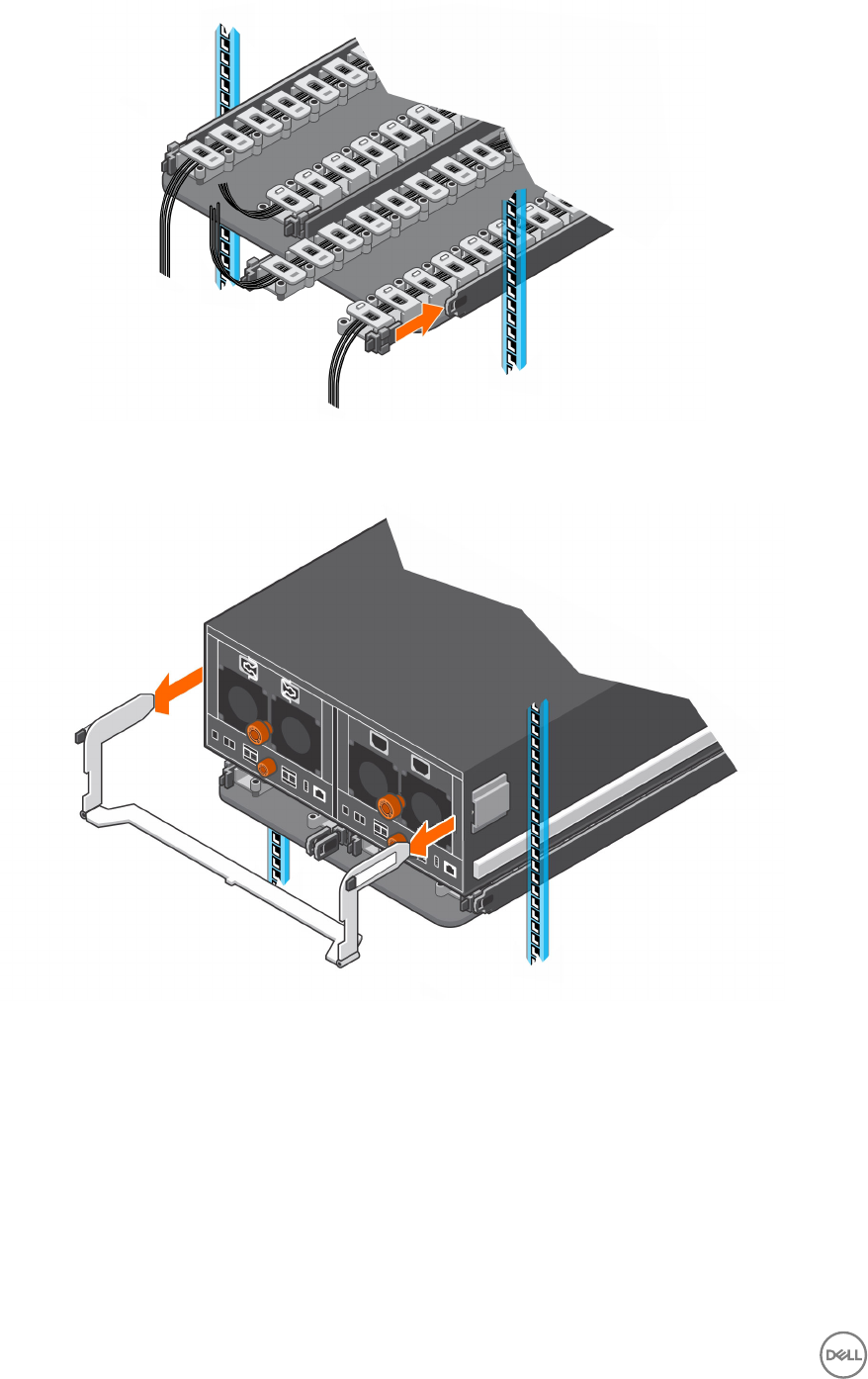
Figure 51. Disconnect Cable Chains from the Tray
6. Press the tabs on the chassis bracket and remove the chassis bracket from the sides of the chassis.
Figure 52. Remove Chassis Bracket from the Chassis
7. Unclip and open all the latches on the cable chains.
48 Replacing SC460 Expansion Enclosure Components
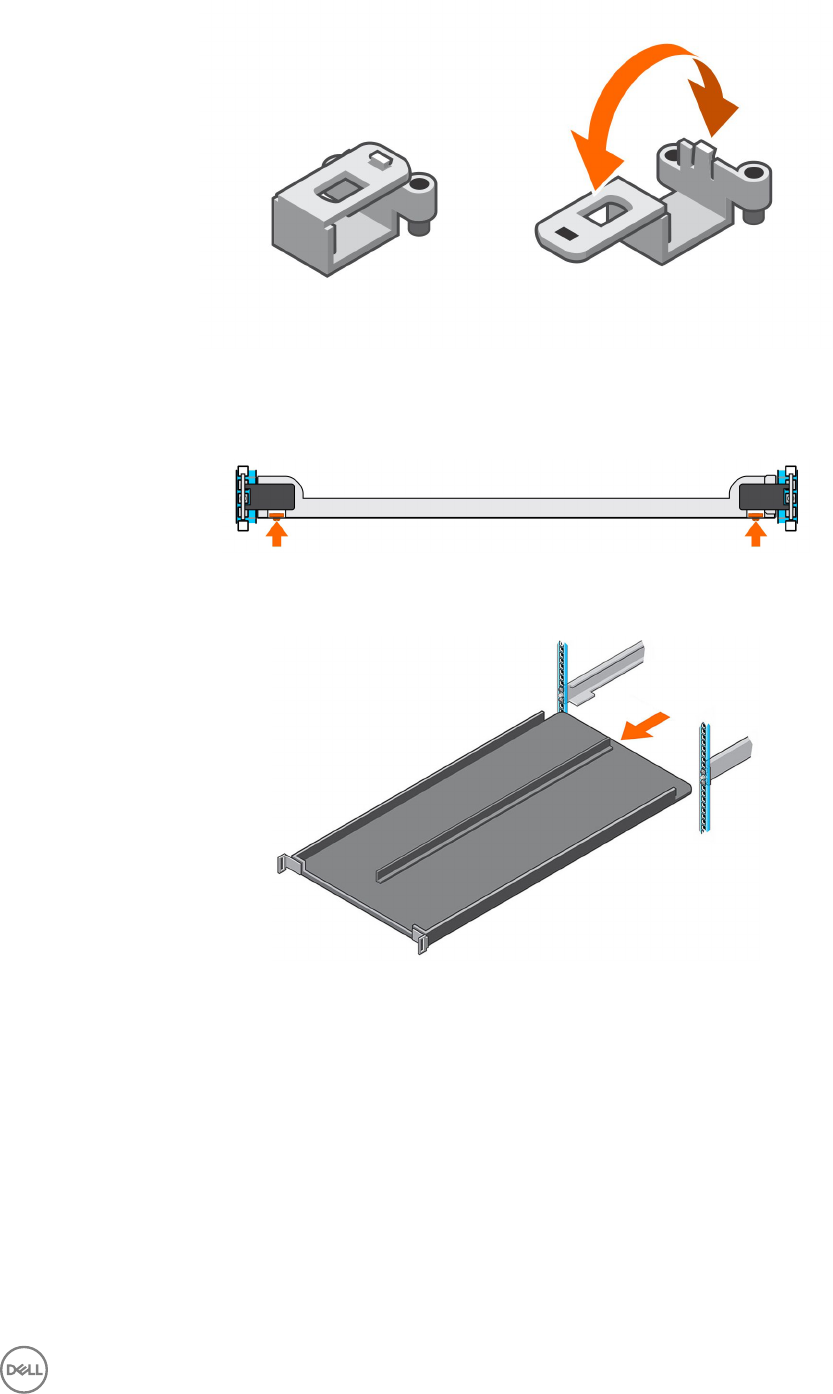
Figure 53. Open the Cable Chain Latches
8. Remove the cables from the cable chains and remove the cable chains from the 1U cable management tray.
9. At the front of the 1U cable management tray, push up on the spring clips to release the tray.
Figure 54. Release Tray Using the Spring Clips
10. Pull the 1U cable management tray towards the front of the rack until it is free from the rails.
Figure 55. Remove Tray from the Rails
11. Remove the 8-32 x 0.75 in. screws from the front and back of the rails.
12. Pull back on the rails until the adaptors clear the front of the rack holes.
13. Remove the rails from the rack.
Replacing SC460 Expansion Enclosure Components 49
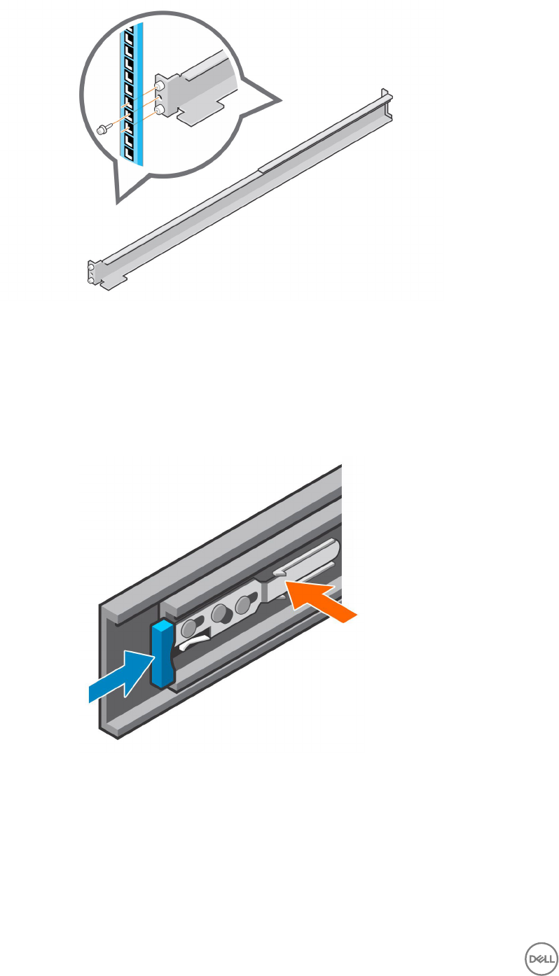
Figure 56. Remove Rails from the Rack
Install the Cable Management Tray
Installation of the 1U cable management tray must be performed during a scheduled maintenance window when the Storage Center
system is unavailable to the network.
Steps
1. If the expansion enclosure rails are installed, push in the blue tab on the rails before installing the 1U cable management tray.
Figure 57. Push in Blue Tab on Expansion Enclosure Rails
2. Align the rails so that the UP arrow is pointed in the correct direction and the end of the rail labeled FRONT is at the front of the
rack.
3. Insert the alignment pins of left and right rails into the mounting holes at the front and back of the rack.
4. Secure the rails by installing 8-32 x 0.75 in. screws into the holes at the front and back of the rails.
50 Replacing SC460 Expansion Enclosure Components
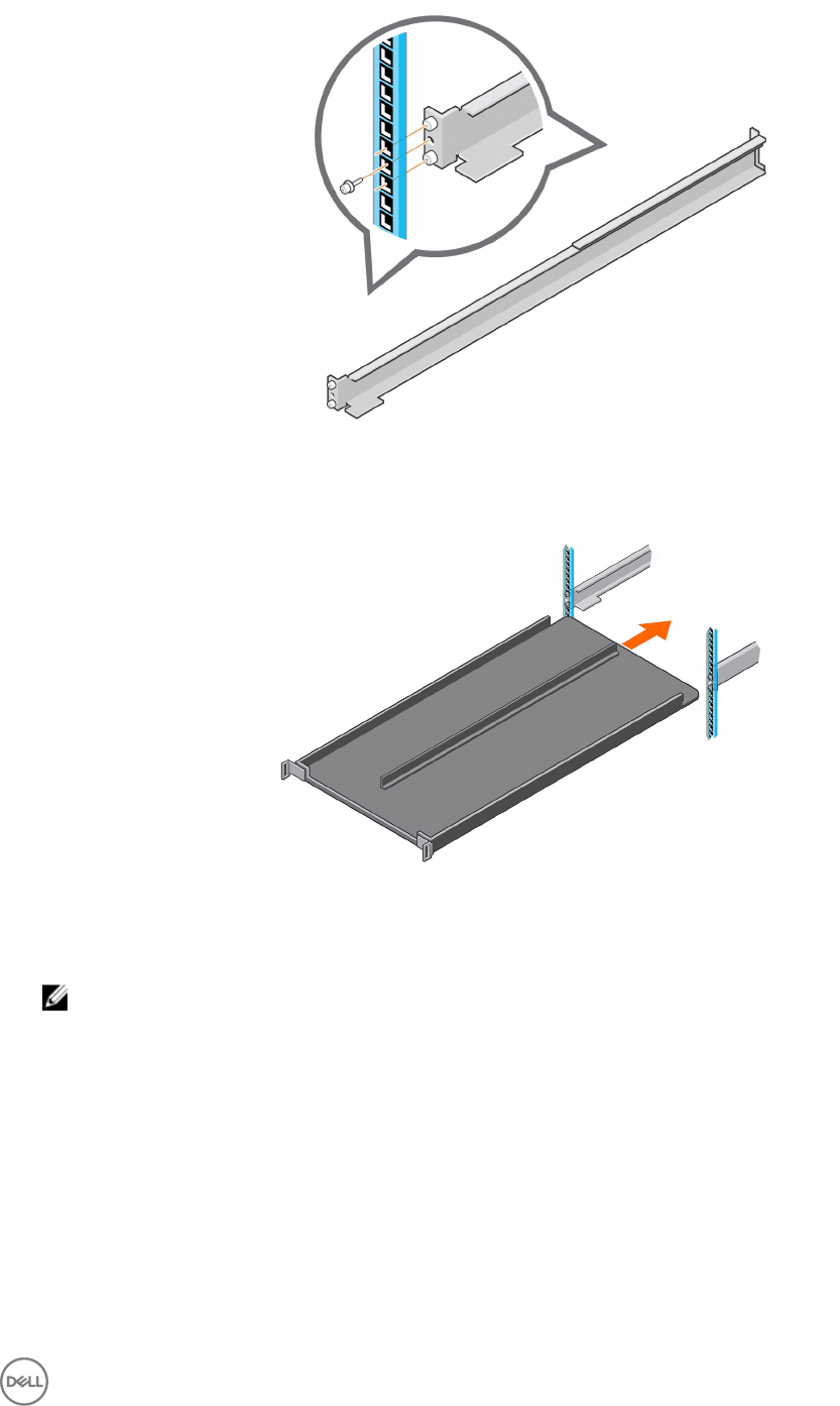
Figure 58. Secure Rails to Rack
5. Align the 1U cable management tray so that the UP arrow is pointed in the correct direction and the side of the tray labeled
FRONT is to the front of the rack
Figure 59. Slide Tray into the Rails
6. Slide the tray into the rails until it locks into place.
7. Prepare the cable chains and route the cables through the cable chains.
NOTE: Label the cables before routing them through the cable chains.
a. Align the cable chains so the latches are facing up and the hinges are all facing each other.
b. Unclip and open all the latches on the cable chains.
Replacing SC460 Expansion Enclosure Components 51
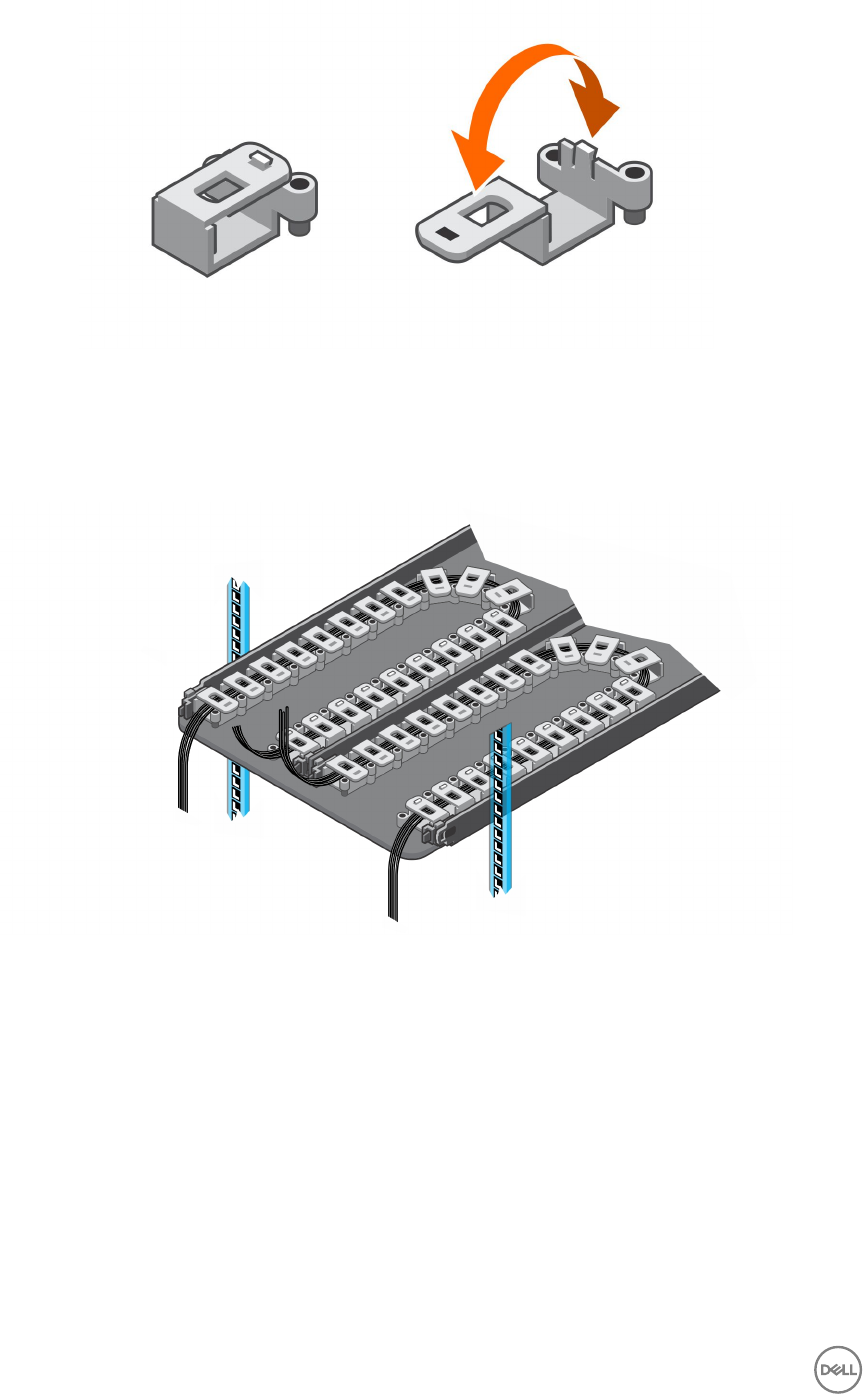
Figure 60. Open the Cable Chain Latches
c. Route two power cables and two Mini-SAS HD cables through each cable chain.
d. Close the latches and make sure that they are snapped shut.
e. Arrange the cable chains to form a "U" shape with the latches facing up.
f. Insert the cable chains through the back side of the tray.
Figure 61. Position the Cable Chains
8. Attach the clips on the cable chains to the tabs on the back of the 1U cable management tray.
52 Replacing SC460 Expansion Enclosure Components
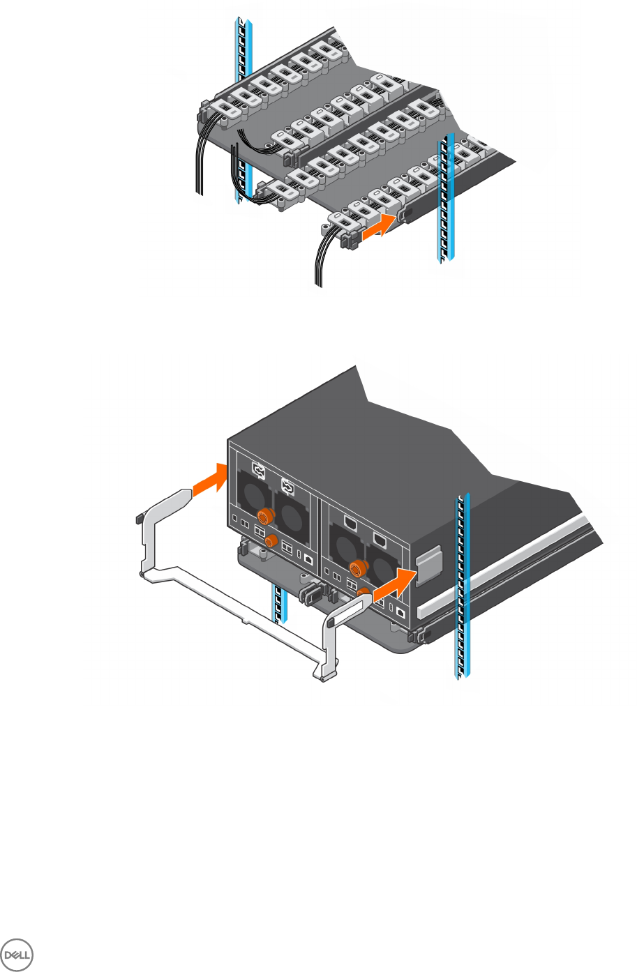
Figure 62. Attach Cable Chains to Tray
9. Install the chassis bracket into the brackets on the side of the chassis.
Figure 63. Install the Chassis Bracket to the Chassis
10. Attach the clips on free end of the cable chains to the center ange on the chassis bracket.
Replacing SC460 Expansion Enclosure Components 53
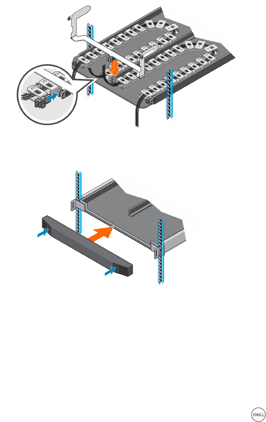
Figure 64. Clip Cable Chains to Chassis Bracket
11. Place the bezel over the front of the tray by pressing the release buttons on the bezel and placing it over the retaining slots on
the tray.
Figure 65. Install the Front Bezel
12. Connect the power cables and Mini-SAS HD cables to the expansion enclosure.
Next steps
1. Power on the expansion enclosure and storage system.
2. Change the operation mode of the Storage Center to Normal.
3. Use SupportAssist to send diagnostic data to Dell Technical Support.
Cable Management Arms
The SC460 expansion enclosure supports cable management arms in racks with a depth of 1200 mm (47.2 in.).
The cable management arms attach to the back of the expansion enclosure chassis and the rack rails.
54 Replacing SC460 Expansion Enclosure Components
Remove the Cable Management Arms
Removal of the cable management arms must be performed during a scheduled maintenance window when the Storage Center
system is unavailable to the network.
Prerequisites
1. Use SupportAssist to send diagnostic data to Dell Technical Support.
2. Change the operation mode of the Storage Center to Maintenance.
3. Use Dell Storage Manager to shut down the storage system connected to the expansion enclosure.
Steps
1. Make sure all the cables are labeled.
2. Disconnect the power cables and the Mini-SAS HD cables from the expansion enclosure
3. Open the cable management arms.
a. Press down on the orange release tab on the right side of the chassis.
Figure 66. Press Orange Release Tab
b. Pull the upper arm away from the right side of the chassis.
Replacing SC460 Expansion Enclosure Components 55
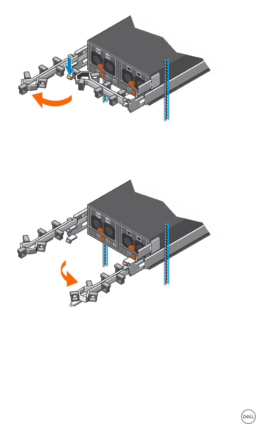
Figure 67. Pull Upper Arm Away from Chassis
c. Press down on the orange release tab on the left side of the chassis.
d. Pull the lower arm away from the left side of the chassis.
Figure 68. Pull Lower Arm Away from Chassis
4. Remove the power cables and the Mini-SAS HD cables from the cable management arms
a. Open the plastic brackets on the cable management arm.
b. Remove the cables from the plastic brackets.
c. Close the plastic brackets on the cable management arm.
5. Remove the lower cable management arm.
a. Press down on the blue release tab, and disconnect the extension arm from the rail bracket.
56 Replacing SC460 Expansion Enclosure Components
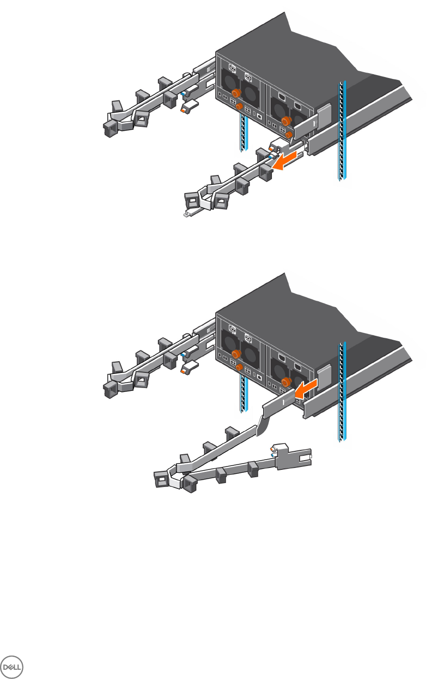
Figure 69. Disconnect Extension Arm from Rail Bracket
b. Press the tab on the cable management arm, and disconnect the arm from the bracket.
Figure 70. Disconnect Cable Management Arm from Bracket
6. Remove the upper cable management arm.
a. Press down on the blue release tab, and disconnect the extension arm from the rail bracket.
b. Press the tab on the cable management arm, and disconnect the arm from the bracket.
Install the Cable Management Arms
Installation of the cable management arms must be performed during a scheduled maintenance window when the Storage Center
system is unavailable to the network.
About this task
Install the cable management arms into a rack with a depth of 1200 mm (47.2 in.).
Replacing SC460 Expansion Enclosure Components 57
Steps
1. Align the retention latch end of the cable management arm with the bracket on the expansion enclosure .
2. Insert the cable management arm into the bracket until you hear an audible click.
The audible click indicates that the cable management arm is secure.
Figure 71. Installing Cable Management Arms
3. Swing the extension arm into alignment with the rail bracket.
Figure 72. Align Extension Arm with Rail Bracket
4. Push the extension arm into the rail bracket until you hear an audible click.
The audible click indicates that the cable management arm is secure.
58 Replacing SC460 Expansion Enclosure Components
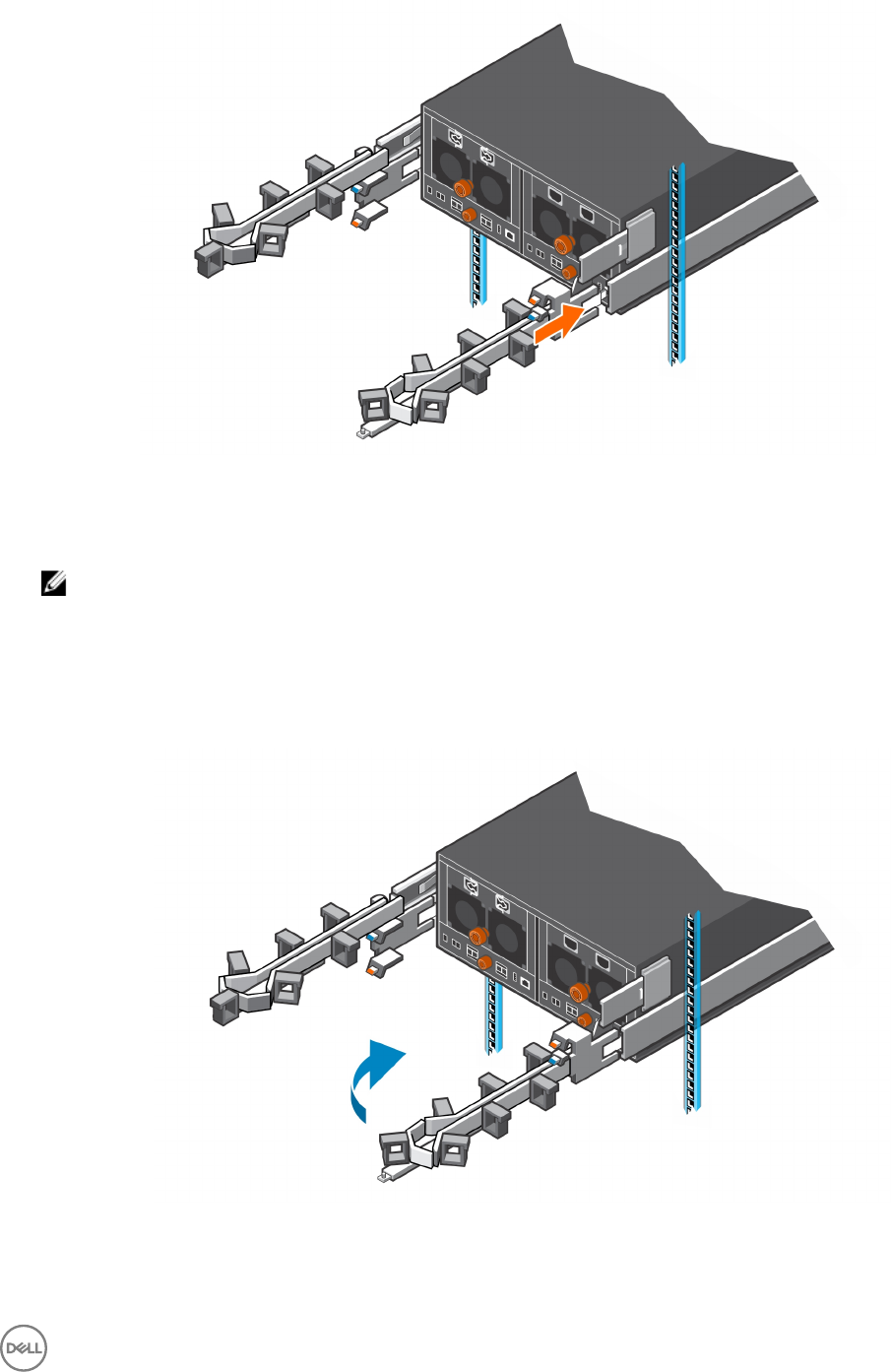
Figure 73. Insert Extension Arm into Rail Bracket
5. Repeat the previous steps for the second cable management arm.
6. Route the cables though the cable management arms.
NOTE: Label all the cables before routing them through the cable management arms.
a. Open the plastic brackets on the cable management arm.
b. Route the power cables and the Mini-SAS HD cables through the plastic brackets.
c. Close the plastic brackets on the cable management arm.
7. Close the cable management arms.
a. Swing the lower arm back and to the left side of the chassis.
Figure 74. Swing Lower Arm to Left Side of Chassis
b. Swing the upper arm back and to the right side of the chassis.
c. Align the securing tab on the right end of the lower arm with the notch over the orange release tab.
Replacing SC460 Expansion Enclosure Components 59
d. Press the tab into the slot until you hear a click.
The click indicates that the arm is secure.
Figure 75. Swing Upper Arm to Right Side of Chassis and Secure Lower Arm
e. Align the securing tab on the left end of the upper arm with the notch over the orange release tab.
f. Press the tab into the slot until you hear a click.
The click indicates that the arm is secure.
Figure 76. Secure Cable Management Arm
8. Verify that the cable management arms are attached at the securing tabs.
60 Replacing SC460 Expansion Enclosure Components
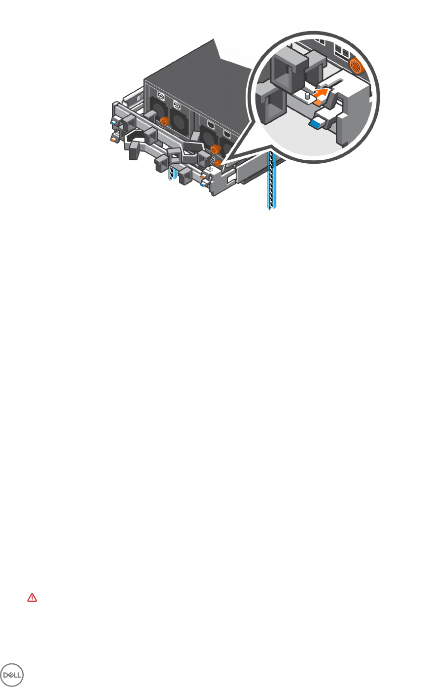
Figure 77. Verify that Cable Management Arms are Secure
9. Connect the power cables and the Mini-SAS HD cables to the expansion enclosure.
Next steps
1. Power on the expansion enclosure and storage system.
2. Change the operation mode of the Storage Center to Normal.
3. Use SupportAssist to send diagnostic data to Dell Technical Support.
Expansion Enclosure Rack Rails
The SC460 expansion enclosure is mounted in a rack using rack rails.
If the rack rails are damaged, they must be replaced.
Remove the Expansion Enclosure Rails
Removal of the expansion enclosure rails must be performed during a scheduled maintenance window when the Storage Center
system is unavailable to the network.
Prerequisites
1. Use SupportAssist to send diagnostic data to Dell Technical Support.
2. Change the operation mode of the Storage Center to Maintenance.
3. Use Dell Storage Manager to shut down the storage system connected to the expansion enclosure.
Steps
1. Make sure all the cables are labeled.
2. Disconnect the power cables and Mini-SAS HD cables from the expansion enclosure
3. Remove the screws that secure the chassis to the rack.
4. Remove the expansion enclosure from the rack rails.
WARNING: Do not attempt to the lift the expansion enclosure by yourself. Always have assistance when lifting the
expansion enclosure. If installed above the lower 20U of a rack, a customer-provided mechanical lift must be used to
avoid injury.
5. Remove the rack rails from the rack.
Replacing SC460 Expansion Enclosure Components 61
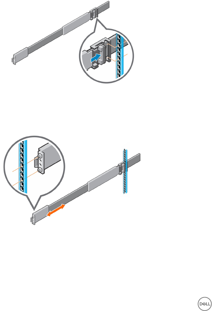
Install the Expansion Enclosure Rails
Installation of the expansion enclosure rails must be performed during a scheduled maintenance window when the Storage Center
system is unavailable to the network.
Steps
1. Adjust the length of the expansion enclosure rails to t the rack.
2. Attach the right rail to the back post of the rack.
a. Align the right rail with the lower two U spaces of the 4U mounting location.
b. With the release latch on the outer part of the rack post, place the catch mechanism over the post.
c. Push the rail back to secure the rail to the rack post.
An audible click indicates that the rail is secure in the post.
d. Make sure the post/catch mechanism is secure and attached to the rack post.
Figure 78. Attach Rail to the Back of the Rack
3. Attach the right rail to the front post of the rack.
a. Align the right rail with the lower two U spaces of the 4U mounting location.
b. Pull the rail forward, with the alignment pins in the middle holes of the bottom two U spaces of the 4U mounting location.
An audible click indicates that the rail is secure in the post.
Figure 79. Attach Rail to the Front of the Rack
4. Secure the rail by installing an M5 x 10 mm screw in the larger of the two holes at the front of the rail.
5. Secure the rail by installing an M5 x 16 mm screw in the larger of the two holes at the back of the rail.
6. Repeat steps 2 through 5 to install the left rail.
7. Mount the expansion enclosure on the rails.
8. Connect the power cables and Mini-SAS HD cables to the expansion enclosure.
62 Replacing SC460 Expansion Enclosure Components

Next steps
1. Power on the expansion enclosure and storage system.
2. Change the operation mode of the Storage Center to Normal.
3. Use SupportAssist to send diagnostic data to Dell Technical Support.
Post-Replacement Procedures
After replacing a component in the SC460 expansion enclosure, start up the SC9000, SC7020, and SC5020 storage systems and
the SC460 expansion enclosures if they were previously shut down, then use SupportAssist to send diagnostic data to Dell Technical
Support.
Start Up the Storage System and Expansion Enclosure
If the storage system and expansion enclosure were previously shut down, perform this procedure to start them up.
1. Power on the expansion enclosure by plugging the power cables into the PSUs.
NOTE: Wait approximately three minutes for the drives in the expansion enclosure to spin up before powering on the
storage system.
2. Plug the power cables into the power supply/cooling fan modules of the storage system.
3. Power on the storage system by pressing the power switches on both power supply/cooling fan modules to the ON position.
4. Use the Dell Storage Manager to make sure the replacement part is recognized and shown as up and running.
Send Diagnostic Data Using Dell SupportAssist
After replacing components, use Dell SupportAssist to send diagnostic data to Dell Technical Support.
1. Use Dell Storage Manager to connect to the Storage Center.
2. In the Summary tab, click Send SupportAssist Information Now, which is located under SupportAssist Actions in the Status
pane.
The Send SupportAssist Information Now dialog box opens.
3. Select Storage Center Conguration and Detailed Logs.
4. Click OK.
Change the Operation Mode of the Storage Center to Normal
Change the operation mode of the Storage Center to Normal after replacing components.
1. Use Dell Storage Manager to connect to the Storage Center.
2. In the Summary tab, click Edit Settings. The Edit Storage Center Settings dialog box opens.
3. Click the General tab.
4. In the Operation Mode eld select Normal.
5. Click OK.
Replacing SC460 Expansion Enclosure Components 63
4
SC460 Expansion Enclosure Technical
Specications
This appendix contains the technical specications for the SC460 expansion enclosure.
Technical Specications
The technical specications of the SC460 expansion enclosure are displayed in the following tables.
Drives
SAS hard drives Dell Enterprise Plus drives
Up to 60 hot-swappable 7.2K RPM 12 Gbps 3.5” SAS hard drives
Connectivity
Congurations SC9000, SC7020, and SC5020 storage systems support up to three SC460 expansion enclosures
Enclosure Management Modules (EMMs)
EMMs Two hot-swappable EMMs with four 12 Gb SAS ports per EMM. The expansion enclosure
supports Mini-SAS HD cables in lengths of 3 m, 4 m, and 5 m.
SAS connectors SAS connectors are SFF-8644 compliant
AC Power
Power supply wattage 1600 W per power supply
AC line voltage 200 to 240 VAC ± 10%, single-phase, 47 to 63 Hz
AC line current (operating
maximum)
4.9 A max at 200 Vac
Power consumption (operating
maximum)
980 VA (931 W) max
Power factor 0.95 min at full load, low voltage
Heat dissipation (operating
maximum)
3.36 x 10⁶ J/hr, (3177 Btu/hr) max
Physical
Height (4U chassis) 17.5 cm (6.89 in.)
Height (4U chassis plus 1U cable management tray) 22.23 cm (8.75 in.)
Width (including rails) 44.45 cm (17.50 in.)
Depth (chassis only) 87.63 cm (34.5 in.)
Maximum depth (fully congured) 92.46 cm (36.4 in.)
64 SC460 Expansion Enclosure Technical Specications

Physical
Weight (maximum conguration) 102.05 kg (225.0 lb)
Environmental
Temperature
Operating 5° to 40°C (41° to 104°F) with a maximum temperature gradation of 10°C per hour
Storage -40° to 65°C (-40° to 149°F) with a maximum temperature gradation of 25°C per hour
Relative humidity
Operating 20% to 80% (noncondensing)
Storage 10% to 90% (noncondensing)
Altitude
Operating -16 to 2300 m (-50 to 7500 ft)
Storage -16 to 10,600 m (-50 to 35,000 ft)
SC460 Expansion Enclosure Technical Specications 65
