Delta Electronics orporated DDP-A020002A DATA COLLECTOR User Manual DDP A020002 A
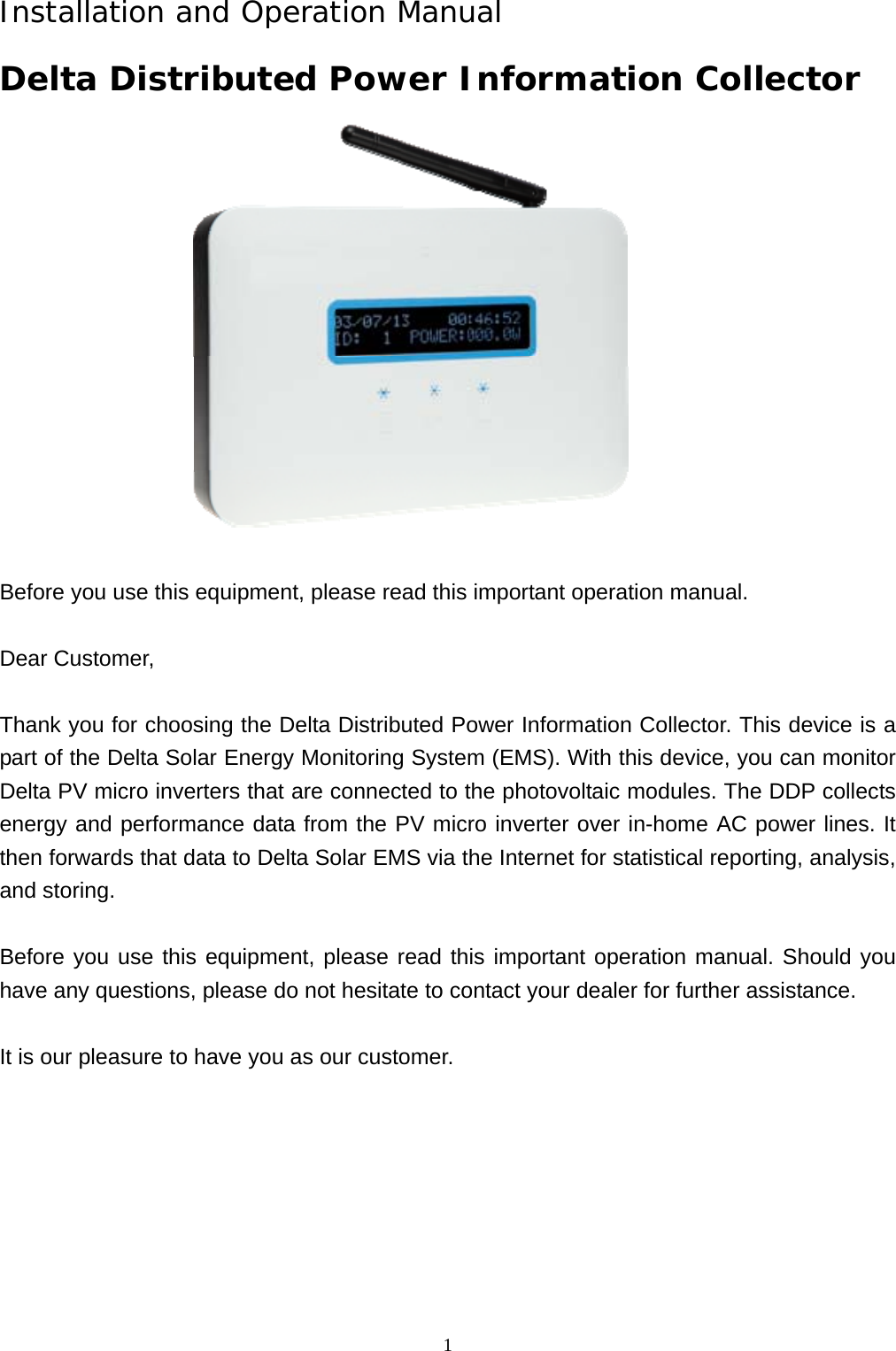
Delta Electronics Incorporated DATA COLLECTOR DDP A020002 A
UserManual.wiki
>
Delta Electronics orporated
>
DDP A020002A User Manual
User Manual.pdf
Navigation menu
Upload a User Manual
Namespaces
Wiki Guide
HTML
PDF
Info
Views
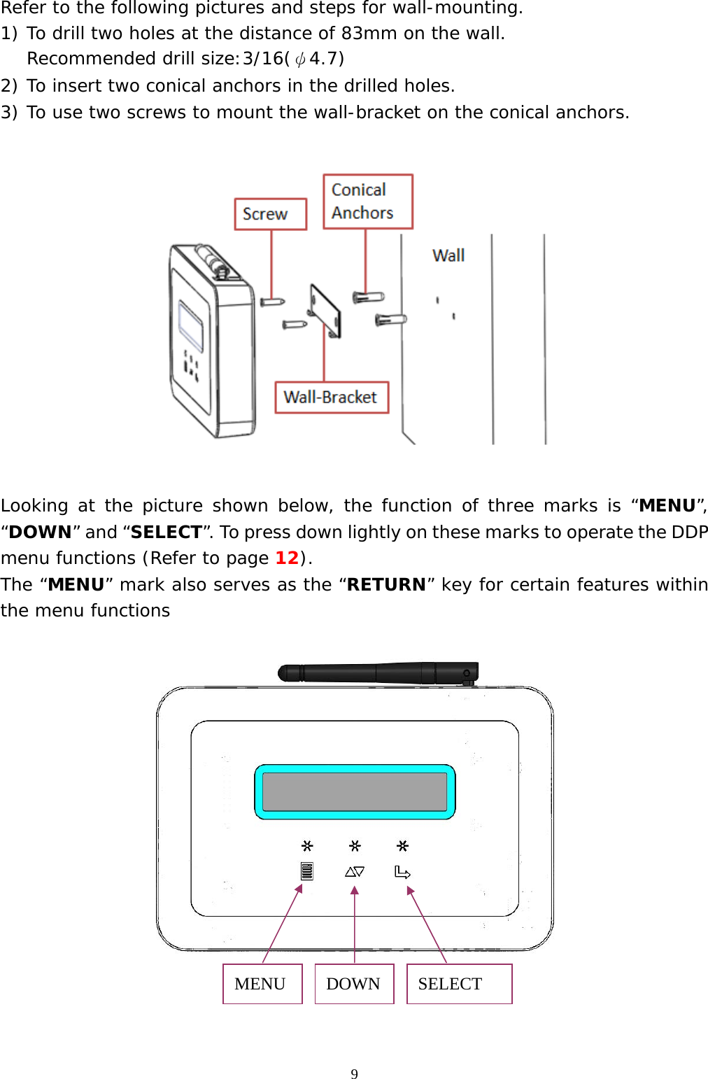
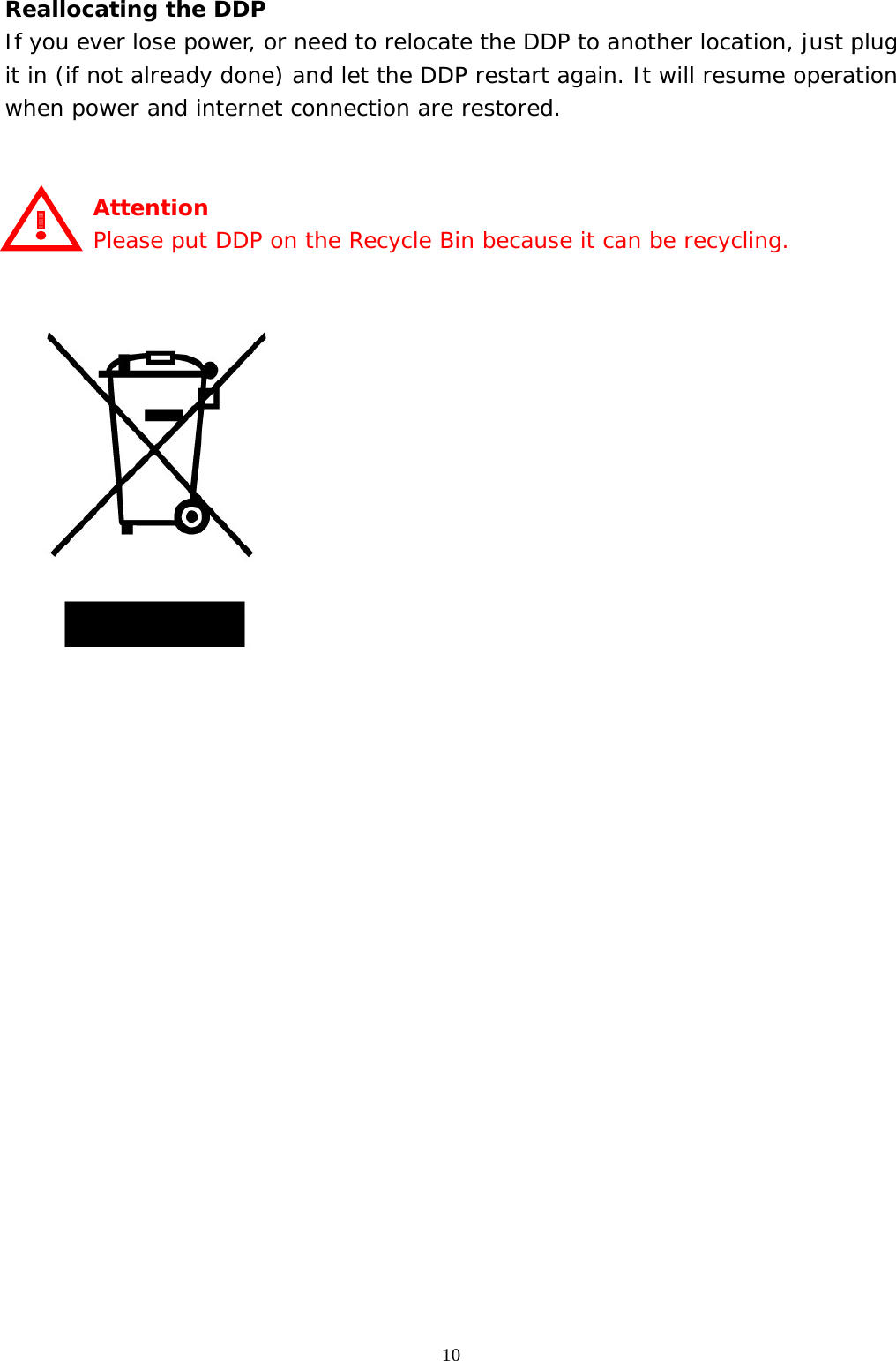
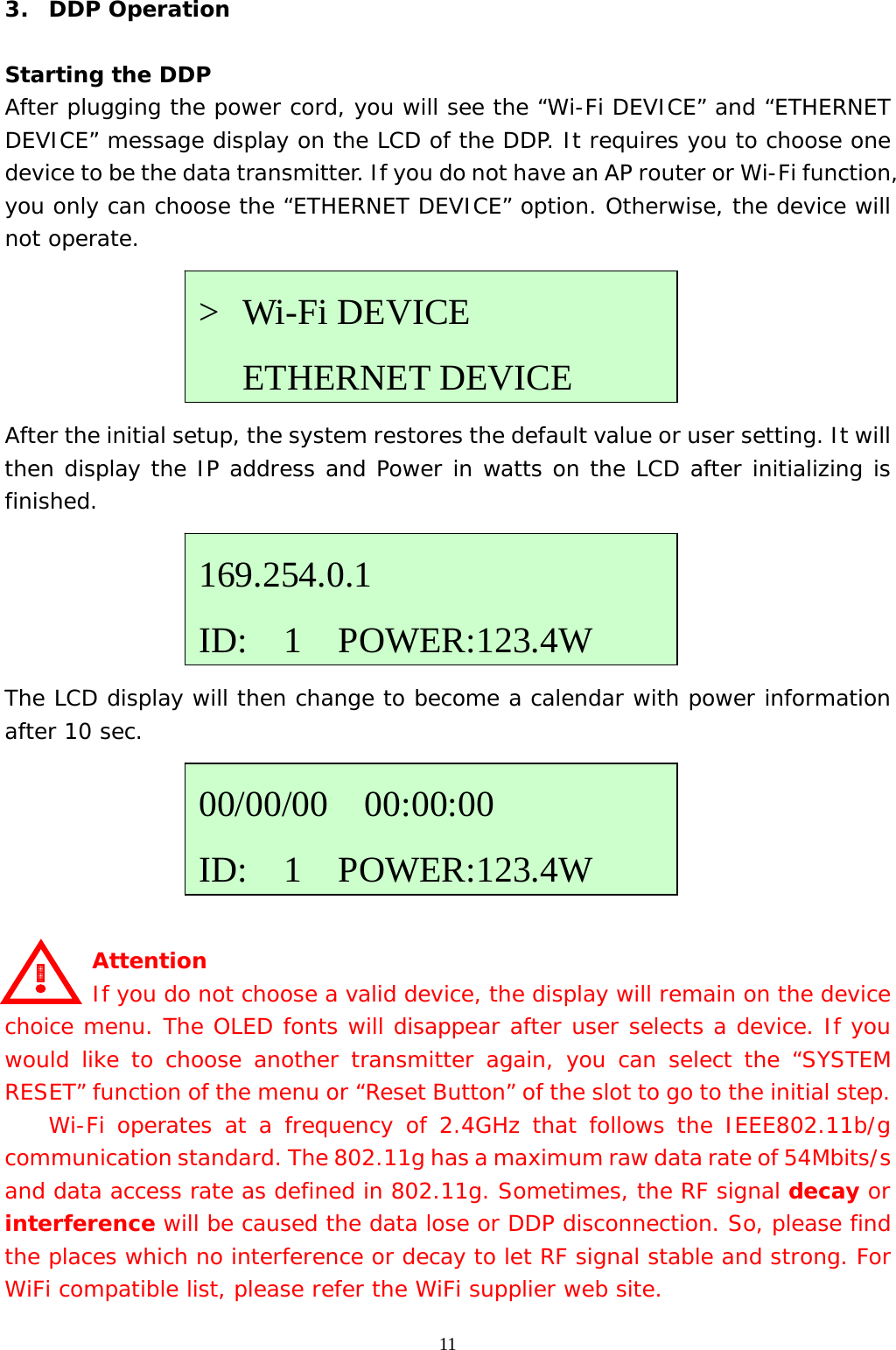
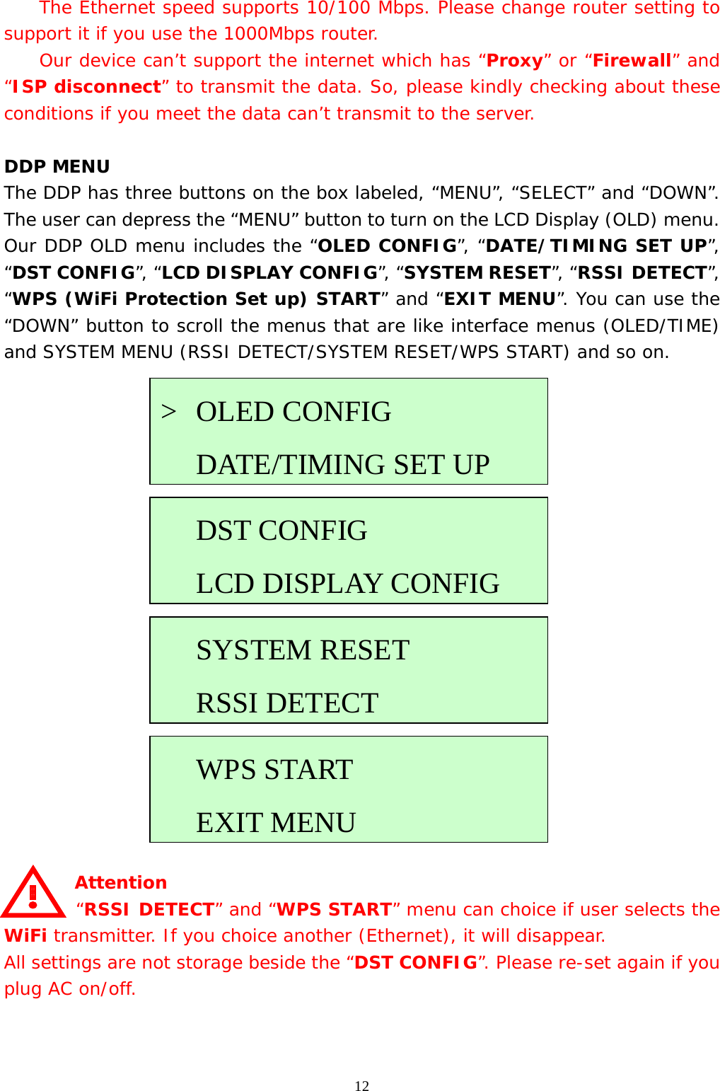
User Manual
Discussion / Help
Navigation