Delta Electronics orporated DDP-A020002A DATA COLLECTOR User Manual DDP A020002 A
Delta Electronics Incorporated DATA COLLECTOR DDP A020002 A
User Manual.pdf
1
Installation and Operation Manual
Delta Distributed Power Information Collector
Before you use this equipment, please read this important operation manual.
Dear Customer,
Thank you for choosing the Delta Distributed Power Information Collector. This device is a
part of the Delta Solar Energy Monitoring System (EMS). With this device, you can monitor
Delta PV micro inverters that are connected to the photovoltaic modules. The DDP collects
energy and performance data from the PV micro inverter over in-home AC power lines. It
then forwards that data to Delta Solar EMS via the Internet for statistical reporting, analysis,
and storing.
Before you use this equipment, please read this important operation manual. Should you
have any questions, please do not hesitate to contact your dealer for further assistance.
It is our pleasure to have you as our customer.
2
Federal Communication Commission Interference Statement
This device complies Part 15 of the FCC Rules. Operation is subject to the
following two conditions: (1) This device may not cause harmful interference, and
(2) this device must accept interference received, including interference that may
cause undesired operation.
This equipment has been tested and found to comply with the limits for a Class B
digital device, pursuant to part 15 of the FCC Rules. These limits are designed to
provide reasonable protection against harmful interference in a residential
installation. This equipment generates, uses and can radiate radio frequency
energy and, if not installed and used in accordance with the instructions, may
cause harmful interference to radio communications. However, there is no
guarantee that interference will not occur in a particular installation. If this
equipment does cause harmful interference to radio or television reception, which
can be determined by turning the equipment off and on, the user is encouraged to
try to correct the interference by one of the following measures:
z Reorient or relocate the receiving antenna.
z Increase the separation between the equipment and the receiver.
z Connect the equipment into an outlet on a circuit different from that to
which the receiver is connected.
z Consult the dealer or an experienced radio/TV technician for help.
FCC Caution: Any changes or modifications not expressly approved by the party
responsible for compliance could void the user's authority to operate this
equipment.
This transmitter must not be co-located or operating in conjunction with any other
antenna or transmitter.
Radiation Exposure Statement:
This equipment complies with FCC radiation exposure limits set forth for an
uncontrolled environment. This equipment should be installed and operated with
minimum distance 20cm between the radiator & your body.
Note: The country code selection is for non-US model only and is not available to
all US model. Per FCC regulation, all WiFi product marketed in US must fixed to US
operation channels only.
Pursuant to IEC60950, the Data Collector involves technologies and materials or
methods provide a level of safety. Any modifications or changes made to this
equipment may void the user warranty.
3
Table of Contents
1. DDP Function…………………………………………………………………………………………….... 4
2. DDP Installation …………………………………………………………………………………………. 5
Preparation…..……………………………………………………………………………………….. 5
Installation ....……………………………………………………………………………………….. 5
For US Users ..……………………………………………………………………………………….. 6
For European Users ..…………………………………………………………………………….. 7
Wall Mounting ………………………………………………………………………………………… 7
Relocating the DDP………………………………………………………………………………..10
3. DDP Operation……………………………………………………………………………..…………….11
Starting the DDP………………………………….………………………………………………..11
DDP Menu....……………………………………………………..………………………………….12
Interface Screen………………………………….………………………………………………..13
Other Screen.…………………………………………………..……………………………………14
System Screen.…………………………………………………..…………………………………14
Restart the DDP………………………………….………………………………………………….17
Normal Operation……………………………….…………………………………………………17
4. Troubleshooting…………………………………………………………………………..…………… 19
Potential Problems and Solutions……………………….…………………………………19
5. DDP Internet Interface………………………………………………………..…………………. 20
Login and Register Screen with Connect to Internet…………..…………….. 20
Monitor with no Internet……………………………………………..…………………..... 29
User Host with Connect to Internet……………………………..…………………..... 31
Event Message……………………………………………..……………….....................32
6. Technical Data…………………………………………………………………………………………… 34
4
1. DDP Function
The DDP information collector is a device for Delta Solar Energy Monitor
System to communicate with Delta PV micro inverter. This device monitors Delta
PV micro inverters that are connected to the photovoltaic modules. The DDP
collects energy and performance data from the PV micro inverter over in-home AC
power lines and forwards that data to the Delta Solar EMS via the Internet for
statistical reporting.
The Delta PV Micro Inverter system is a device that converts the solar panel DC
output into grid-compliant AC power. This fully integrated device can maximize
the modules' energy production by utilizing a sophisticated Maximum Power Point
Tracking (MPPT) algorithm. This integrated system maximizes energy harvest and
provides individual AC output without hazardous voltage. And in case of any
failure of any individual solar panel or inverter, this will not impact other modules
and inverter operations. Unlike traditional center inverter structures, this PV
micro inverter system provides true redundancy and eliminates hazardous
voltage levels.
The Delta Solar EMS collects and analyzes the per-module data from each PV
micro inverter.
This system automatically detects any shortfall in energy production. It is easy for
a repair technician to locate the failed solar module and perform the necessary
replacement. It monitors and stores data on a constant basis. User can access
the data for commercial or personal use.
The DDP is designed for easy installation and is easy to operate. User does not
need any specialized equipment. It simply plugs to the grid tied wall AC outlet and
routers for communications with the Delta Solar EMS. The DDP communicates
with the individual PV micro inverters over the existing power lines in the
residence or business.
After installation and device scanning, it assembles an internal database of all
known Delta PV micro inverters at the site it manages. As a constant monitor, the
DDP utilizes the customer’s site broadband router to forward information to the
Delta Solar EMS. The DDP also reports any error conditions that affect the DDP or
the PV micro inverters. You can view both energy data and error conditions in the
Delta Solar EMS.

5
2. DDP Installation
Preparation
Before you install this device, first please check if the following items are included
in the DDP package box. If there is any item missing, please contact your dealer
for a free replacement:
z DDP Communications
z Ethernet cable
z Wi-Fi antenna
z AC power cord
z A kit of conical anchors and screws
z Wall bracket
z User manual
The following networking environment is required for install DDP:
z A reliable broadband internet connection
z Web browser to view DELTA Solar EMS webpage
z Router / LAN or Router/WLAN with Ethernet port (or AP Router with Wi-Fi
connection)
z Grid connected standard AC electrical outlet. Please do not plug DDP into a
transformer protection device like a power strip, surge protector, or
un-interruptible power supply. These devices could block the
communication signal.
Installation
Pick a suitable location to place your DDP device. We suggest this location to be as
close as possible to the wireless AP (if you have the Wi-Fi function) or the Service
Panel (Load center). This DDP is designed to perform at an environment between
-10 degrees C to +40 degrees C that should cover the majority of indoor
environments.
Attention
Please call the installer if you have below conditions:
1. You are unable to understand how it works.
2. You notice any operation anomalies.
3. You don’t understand or fear that you can’t complete the fully install
steps.
4. This device must be installed in rooms with suitable environmental
conditions (see technical data).
DO NOT install outdoors.
6
5. Don’t equip to operate in environments that have particular
flammability or explosive conditions.
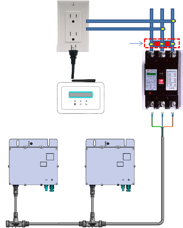
For US Users:
See below PV micro inverter system installation instructions. After installing
Data Collector, you can plug into 120Vac wall socket. In order to have good
communication between Data Collector and PV micro inverter system, you
should install a power line phase coupler(see below picture). It is an in-box
passive circuit that couples power line signal for different phase of residential
power line communication. After installation, you should set Internet Interface.
See page 20 to finish all of installation.
DataCollector
L1L2
N
120V,60Hz
L1orL2
Coupler
L1‐L2,240V,60Hz
NoFuse
Breaker
USPVMicro‐InverterS
y
stem
7
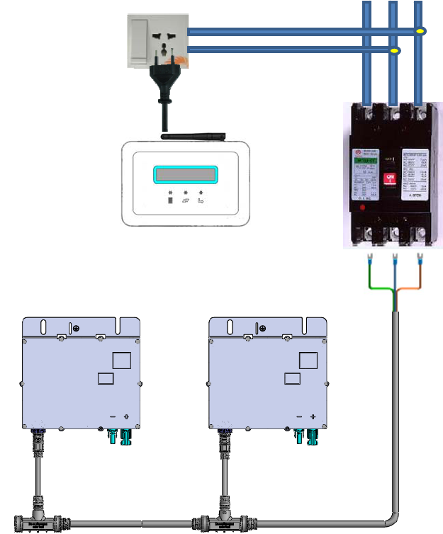
For European Users:
See below PV micro inverter system installation instructions. After installing Data
Collector, you can plug into 230Vac wall socket. And then, you should set Internet
Interface. See page 20 to finish all of installation.
Wall Mounting
(Caution: For safety consideration, the device must be mounted on a
wall)
Customer can choose to wall mount this device.
DataCollector
PEL
N
L‐N,230V,50Hz
230V,50Hz
NoFuse
Breaker
Euro
p
ean PVMicro‐Inverter
8
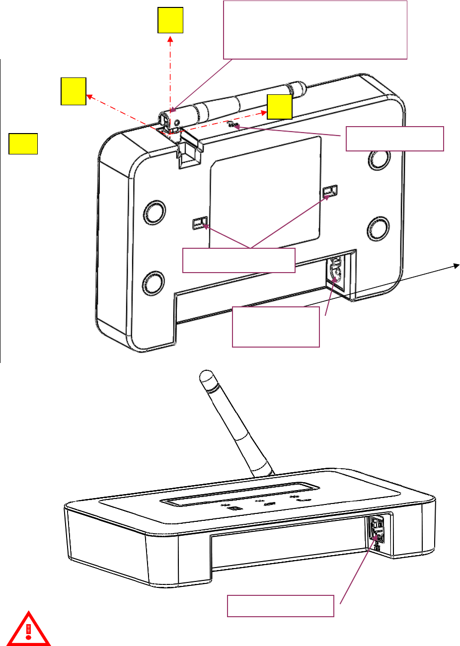
Attention
Please follow rotating angles of Antenna same as the above picture.
Please install during the daytime to make sure it can connect with
inverters.
ROTATING ANGLE OF ANTENNA
90° (AXIS: XÆ Z)
180° (AXIS: XÆ YÆ -X)
-
X
SOCKET FOR
AC CABLE
PHONE JACK RJ45
SLOT FOR RESET
For wall-mounting
X
Y
Z
9
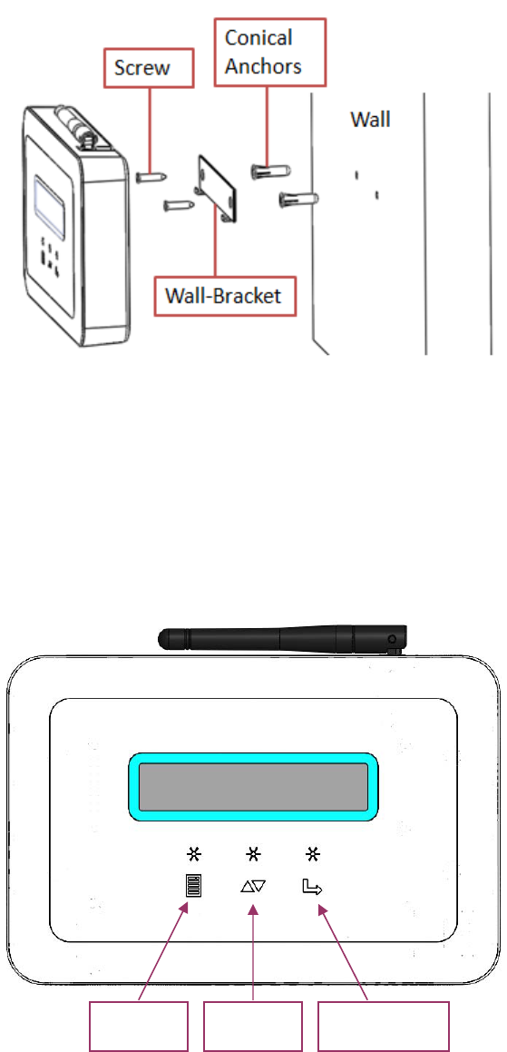
Refer to the following pictures and steps for wall-mounting.
1) To drill two holes at the distance of 83mm on the wall.
Recommended drill size:3/16(ψ4.7)
2) To insert two conical anchors in the drilled holes.
3) To use two screws to mount the wall-bracket on the conical anchors.
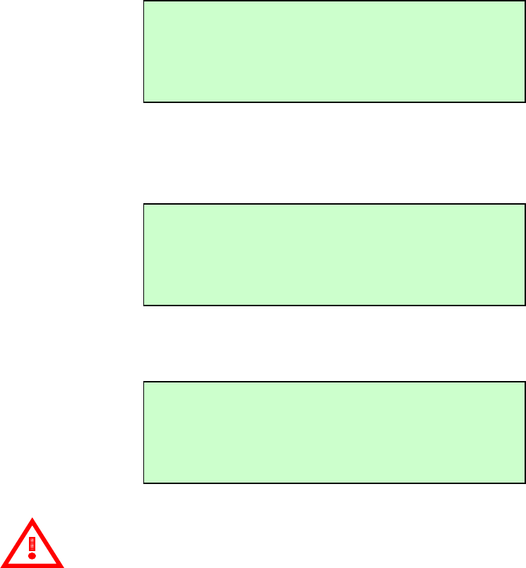
Looking at the picture shown below, the function of three marks is “MENU”,
“DOWN” and “SELECT”. To press down lightly on these marks to operate the DDP
menu functions (Refer to page 12).
The “MENU” mark also serves as the “RETURN” key for certain features within
the menu functions
MENU DOWN SELECT

10
Reallocating the DDP
If you ever lose power, or need to relocate the DDP to another location, just plug
it in (if not already done) and let the DDP restart again. It will resume operation
when power and internet connection are restored.
Attention
Please put DDP on the Recycle Bin because it can be recycling.
11
3. DDP Operation
Starting the DDP
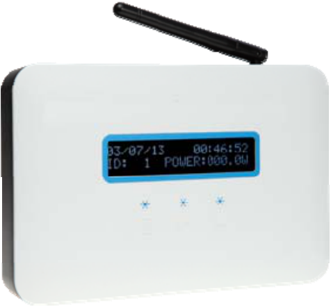
After plugging the power cord, you will see the “Wi-Fi DEVICE” and “ETHERNET
DEVICE” message display on the LCD of the DDP. It requires you to choose one
device to be the data transmitter. If you do not have an AP router or Wi-Fi function,
you only can choose the “ETHERNET DEVICE” option. Otherwise, the device will
not operate.
After the initial setup, the system restores the default value or user setting. It will
then display the IP address and Power in watts on the LCD after initializing is
finished.
The LCD display will then change to become a calendar with power information
after 10 sec.
Attention
If you do not choose a valid device, the display will remain on the device
choice menu. The OLED fonts will disappear after user selects a device. If you
would like to choose another transmitter again, you can select the “SYSTEM
RESET” function of the menu or “Reset Button” of the slot to go to the initial step.
Wi-Fi operates at a frequency of 2.4GHz that follows the IEEE802.11b/g
communication standard. The 802.11g has a maximum raw data rate of 54Mbits/s
and data access rate as defined in 802.11g. Sometimes, the RF signal decay or
interference will be caused the data lose or DDP disconnection. So, please find
the places which no interference or decay to let RF signal stable and strong. For
WiFi compatible list, please refer the WiFi supplier web site.
169.254.0.1
ID: 1 POWER:123.4W
> Wi-Fi DEVICE
ETHERNET DEVICE
00/00/00 00:00:00
ID: 1 POWER:123.4W
12
The Ethernet speed supports 10/100 Mbps. Please change router setting to
support it if you use the 1000Mbps router.
Our device can’t support the internet which has “Proxy” or “Firewall” and
“ISP disconnect” to transmit the data. So, please kindly checking about these
conditions if you meet the data can’t transmit to the server.
DDP MENU
The DDP has three buttons on the box labeled, “MENU”, “SELECT” and “DOWN”.
The user can depress the “MENU” button to turn on the LCD Display (OLD) menu.
Our DDP OLD menu includes the “OLED CONFIG”, “DATE/TIMING SET UP”,
“DST CONFIG”, “LCD DISPLAY CONFIG”, “SYSTEM RESET”, “RSSI DETECT”,
“WPS (WiFi Protection Set up) START” and “EXIT MENU”. You can use the
“DOWN” button to scroll the menus that are like interface menus (OLED/TIME)
and SYSTEM MENU (RSSI DETECT/SYSTEM RESET/WPS START) and so on.
Attention
“RSSI DETECT” and “WPS START” menu can choice if user selects the
WiFi transmitter. If you choice another (Ethernet), it will disappear.
All settings are not storage beside the “DST CONFIG”. Please re-set again if you
plug AC on/off.
> OLED CONFIG
DATE/TIMING SET UP
DST CONFIG
LCD DISPLAY CONFIG
SYSTEM RESET
RSSI DETECT
WPS START
EXIT MENU
13
Interface Screen (OLED / DATE)
This screen lets the user adjust the function status. User can press “OLED
CONFIG” menu to choose the OLED fonts display or dormancy mode. You can
manually configure the calendar when you choose the enable item in
“DATE/TIMING SET UP” menu.
In OLED menu, the user can select “POWER ALWAYS ON” or “POWER SAVE MODE”.
“POWER ALWAYS ON” means the OLED fonts will always stay lit. “POWER SAVE
MODE” means the OLED fonts will darken after 30 sec and LED will blink at right
up side. The OLED fonts will light again when the user presses any buttons. The
default value is “POWER SAVE MODE”.
In DATE/TIMING menu, you can adjust the calendar manually. The ‘#’ will appear
when you press “SELECT” and then you can adjust it. The value adjusts
individually as you press the “DOWN” button. The character will blink per second
when you hold it. It will jump to next value to adjust when you press the “SELECT”
button. The ‘#’ will disappear when set up is finished.
You do not need to adjust calendar manually if you register with our Delta Solar
EMS webpage. It can get the local time automatically. The default values are
00/00/00 00:00:00.
Attention
The DATE indicate as: Year / Month / Day
The TIME indicate as: Hour/ Min / Sec
OLED CONFIG
DATE/TIMING SET UP
POWER ALWAYS ON
# POWER SAVE MODE
DATE: 00/00/00
TIME: 00:00:00

14
Other Screen (DST / LCD DISPLAY)
In this screen, you can choice Daylight Saving Time (DST) mode or change the
LCD display information.
DST is different with other countries. So, you can select the DST menu to
“ENABLE” (+1 hour) or “DISABLE” (-1 hour) it to choice. The default value is
“DISABLED”.
LCD DISPLAY can change the inverter power information to inverter status. The
status event message can be referenced on page 32. The default is POWER
DISPLAY.
STATUS display: (Status must be referred page 32)
System Screen (SYSTEM RESET / RSSI DETECT / WPS START)
This screen has two situations.
It includes “RSSI DETECT” and “WPS START” menu if user choices WiFi to be
transmitter.
ENABLE
#DISABLE
DST CONFIG
LCD DISPLAY CONFIG
#POWER DISPLAY
STATUS DISPLAY
169.254.0.1
ID: 1 STATUS: XXXX
SYSTEM RESET
RSSI DETECT
WPS START
EXIT MENU

15
The other has no above menus if user choices Ethernet to be transmitter.
If you choose the wrong one or want to change the transmit device, you can go
into the “SYSTEM RESET” item and then display confirm message “RESET
DEVICE?” It will return to select the transmit device menu again by pressing
“SELECT”. Note, it will also clear all the setting after pressing. You can return to
original menu if you press “MENU”. It does not affect the PLC data of the memory
but system data of DDP will return to default. So, it will display power information
if you register EMS again.
The WiFi signal strength detect between DDP with AP router if user press “RSSI
DETECT”. It will display “SCANNING…” if you have already connected with AP and
press it.
Otherwise, it will display “SCAN CAN’T WORK PLEASE CONNECT AP” message if
user don’t connect with AP first.
It will take few seconds (less than 1 min) to detect DDP with AP router signal
strength. Then, it will display “SCANNING FINISH PRESS ’MENU’ BACK” message
to indicate the scan function has finished.
RESET DEVICE?
MENU:NO SELECT:YES
SCANNING…
SCANNING FINISH
PRESS ‘MENU’ BAC
K
SYSTEM RESET
EXIT MENU
SCAN CAN’T WORK
PLEASE CONNECT AP

16
You can press “MENU” button back to menus or back to power information after 30
second timeout.
You will see the WiFi signal strength display on LCD as bellow:
If your AP router has logo and use the WiFi to be transmitter, it also can
use the WPS function to do quick communicate with AP router. It just only can
support the security above WPA mode, such as WPA, WPA2…etc. (It can’t
support WEP serials.)
It will display the “WPS EXCUTION PLEASE WAIT…” if user presses the “WPS
START”.
Please press the WPS button on the AP router (you can refer AP router manual to
find it), then AP router indicator will blinking and start to find the device which
want to connect each other.
It will cost about 30 seconds to connect and get new IP if it connects successful.
The success message will display as below:
It will reconnect 3 times if AP router blinking doesn’t dark and find any devices. So,
it will cost almost 1’30 seconds. The “CONNECT FAIL” message display as below
if it also can’t find any devices. Press “MENU” and then press “ENTER”, you also
can do WPS again.
It will display as below message as you press “WPS START” function again if you
have already connected successful.
192.168.xxx.xxx Web
ID: 1 POWER:123.4W
WPS EXCUTION
PLEASE WAIT…
CONNECT SUCCESS
PRESS ‘MENU’ BAC
K
CONNECT FAIL
PRESS ‘MENU’ BAC
K

17
NOTE:
We suggestion you don’t use WPS function if your AP router doesn’t have
logo.
If you want to do it when you have already connected, you must press “SYSTE
RESET” to do again.
Finally, it will return to power information when you press the “EXIT MENU”.
Restart the DDP
If the utility power fails, or you need to restart the DDP equipment, just press the
Reset button to start up again. It will resume operation when power and internet
connection are restored. If you use the Wi-Fi transmittal method, you need to
reset again to connect the internet. When it resumes operation, the LCD window
displays the “Wi-Fi DEVICE” and “ETHERNET DEVICE” message. The LCD window
will display the following:
After the restart step, normal operation resumes.
Normal Operation
Begins or resumes normal operation when the DDP system initialization is
complete. At this point, the LCD will display as below:
On screen display values are indicated as bellow:
z The IP address, such as: 192.168.x.x (your actual local IP will be
different from your AP configuration)
> Wi-Fi DEVICE
ETHERNET DEVICE
192.168.xxx.xxx Web
ID: 1 POWER:123.4W
IT HAS CONNECTED
WPS CAN NOT WOR
K
18
z The Web appears if the DDP gets DHCP from user AP router. Otherwise,
it will disappear.
z Indication of the present panel ID, in ID: xxx (where xxx is a value which
get from the PV micro inverter serial number )
z Indication of the present power-production, in power: xxx W (where
xxx is a value from the actual panel value)

19
4. Troubleshooting
If you experience problems, some of them are described below. For system status
and event message information, please see Event Messages on page 32.
Potential Problems and Solutions
IP Address Problem:
If the IP address displayed on the DDP LCD does not match or you get the DHCP
subnet from your internal network or AP router, it always shows “169.254.0.1”,
it means it was unsuccessful to obtain a DHCP from your AP router. Check network
connectivity to the AP router or other DHCP server. You may also wish to contact
your Internet Service Provider or refer to your AP router documentation for
assistance or setting.
Attention
WiFi signal strength will depend on user’s AP router distance. So, please
possibly to set up our device near with your AP router to make sure RF signal have
low decay or interference. You must change your AP router channel to others if
you meet our device not easily to connection each other. If interference serious, it
easily to meets this symptom.
20
5. DDP Internet Interface
You need the Internet to connect with our Delta Solar EMS webpage to monitor
and analyze the information recorded.
If you use Wi-Fi to be your transmitter type, please follow the method below to
connect to our Delta Solar EMS webpage step by step. If you press the “WPS
START” to get the new IP address successful, you can skip to step 4 operate.
Skip to step 5 and press the I Accept button if you use the ETHERNET.
Login and Register Screen with Connect to Internet
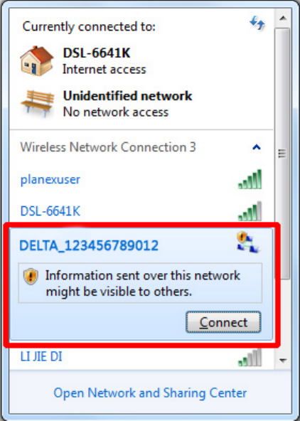
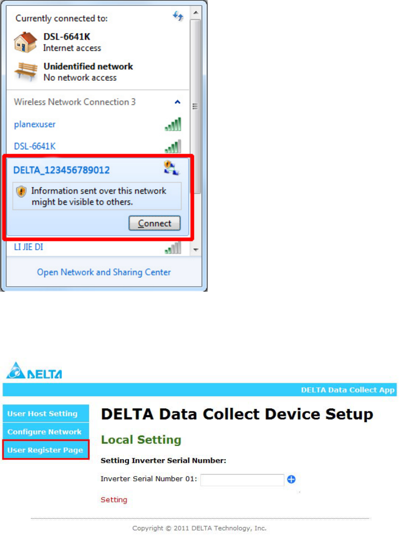
Step 1. Please select the DELTA_XXXXXXXXXXXX and connect to it after the
system startup. X is Wi-Fi MAC address.
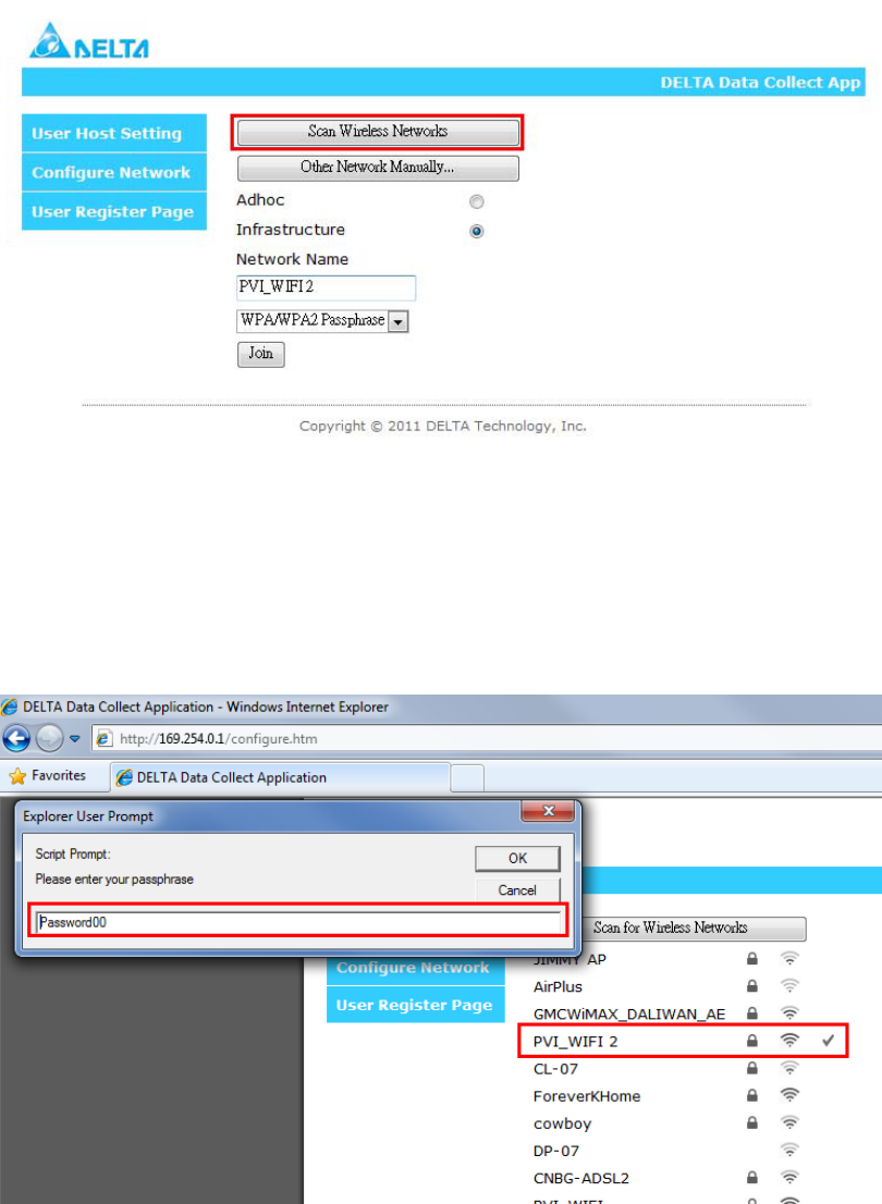
Step 2. Press 169.254.0.1 on your notebook (or computer) with Wi-Fi function to
connect device. Then press Scan Wireless Networks button. You should
see all AP router lists after device detecting has finished.
21
Step 3. Please select your AP router to be your data transmitter. There is no need
to do anything further if your AP router is not set to encryption mode.
Otherwise, input the password if your AP router is set to encryption protect
mode.
SCAN Wireless Networks:
Other Network Manually:
22
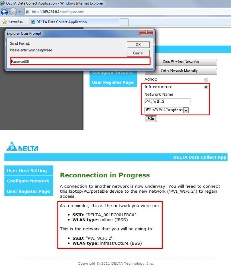
Step 4. Your PC must change the AP router which you selected. Then your PC can
communicate with the DDP again.
23
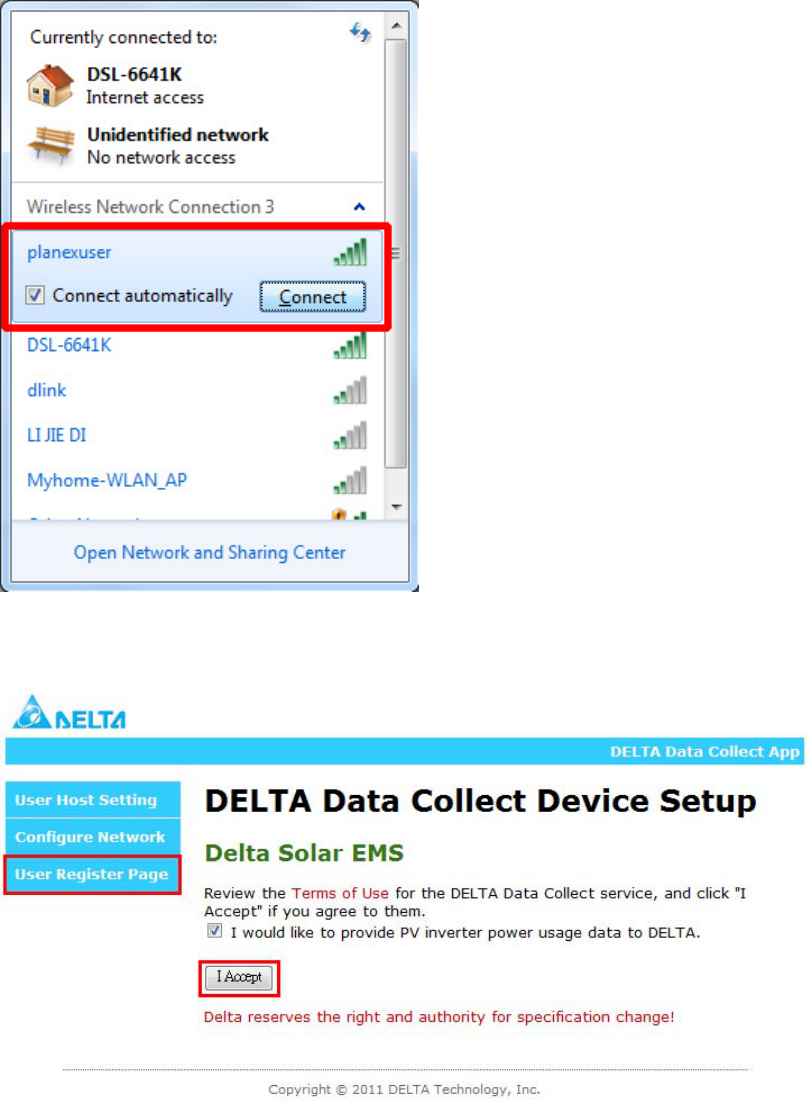
Step 5. After selecting finish, user needs to choice “User Register Page” firstly
and then, pressing the I Accept button to connect with our website.
Step 6. Once the Delta Solar EMS appears, the user needs to register one new
account for our database. You must register one account for our webpage
to monitor the information if you have never registered.
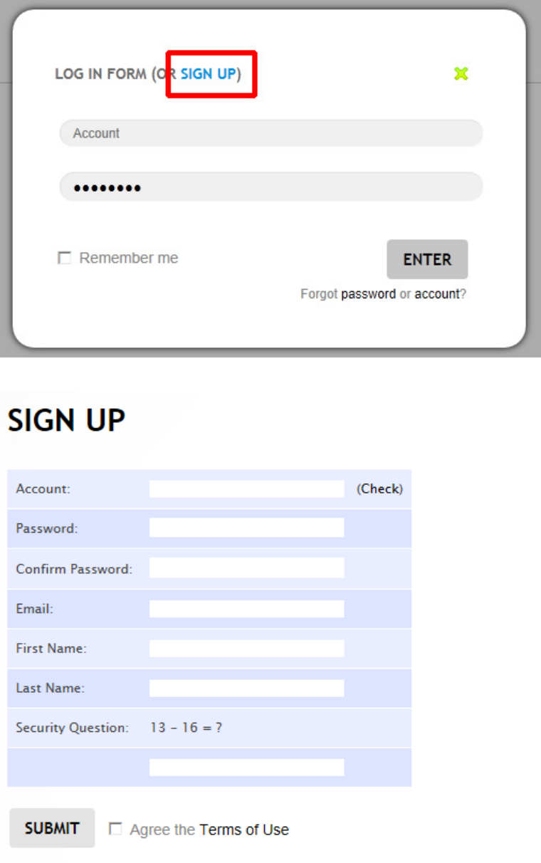
24
Step 7. Register your detail personal data if you are new user.
Step 8. Login Delta Solar EMS.
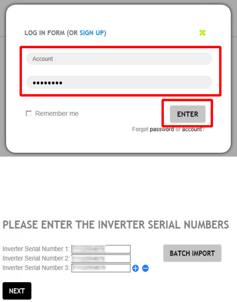
25
Step 9. If you are newer, it will show the PV micro inverter Serial Number
register information. You just register serial numbers which you have.
Or else skip to step 12 to reactive device or update setting.
Register
Step 10. Register the collect name, time zone and location
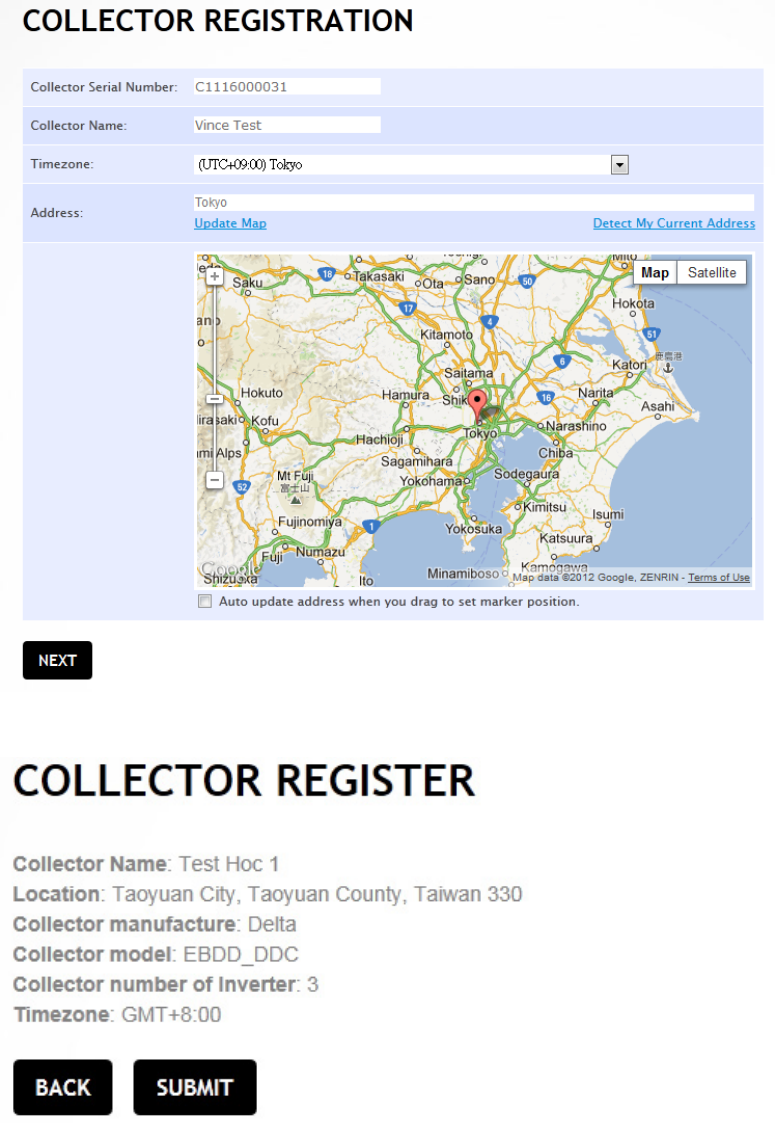
26
Step 11. Check the DDP and other information
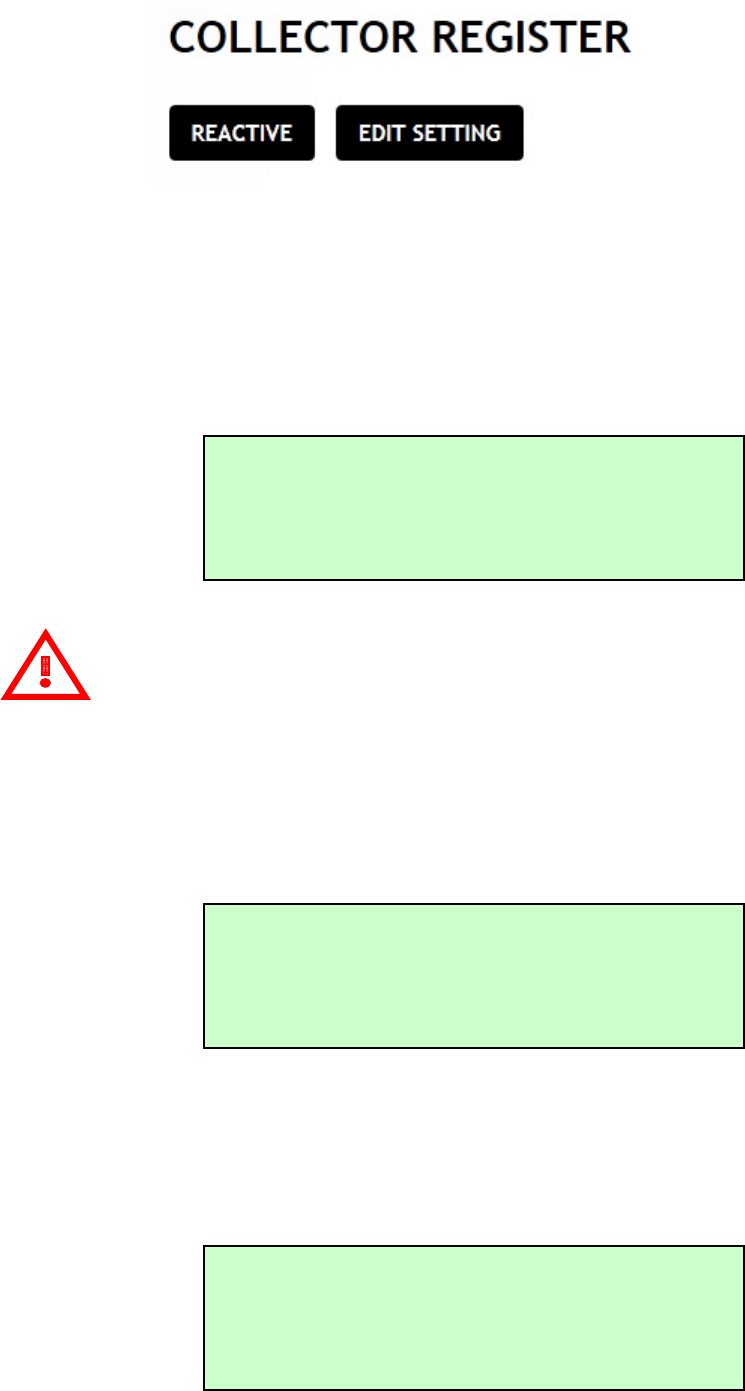
Step 12. You will see this page if you ever registered your device. There are
two statuses will display as bellow: one is reactive directly if you ever
register. Another is updating the inverter serial number and collector
location information if you want to add new inverters or change your DDP
location.
27
Step 13. After pressing the “SUBMIT” or “REACTIVE”, you can see the message
“PLEASE AWAIT CONFIG” display on LCD. The time count is depending on
your PV micro inverter numbers to connect with DDP.
The power information displays after time counting finishes.
Attention
The DDP connects with PV micro inverters by using the power line
communication (PLC) method. It takes some times to connect, but it doesn’t
connect successful because the PLC can’t verify success. So, it will display two
statuses as bellow if time count has finished.
Status 1: It connects successful if LCD displays the power information after few
minutes.
Status 2: It connects fail if LCD doesn’t display power information. For this status,
it needs to spend some time to connect again until it connects
successful. Please kindly inform our service if it always can’t display
after 20 min or above.
PLEASE AWAIT CONFIG
XX:XX
192.168.xxx.xxx Web
ID: 1 POWER:123.4W
192.168.xxx.xxx Web
ID: 1 POWER: W
28
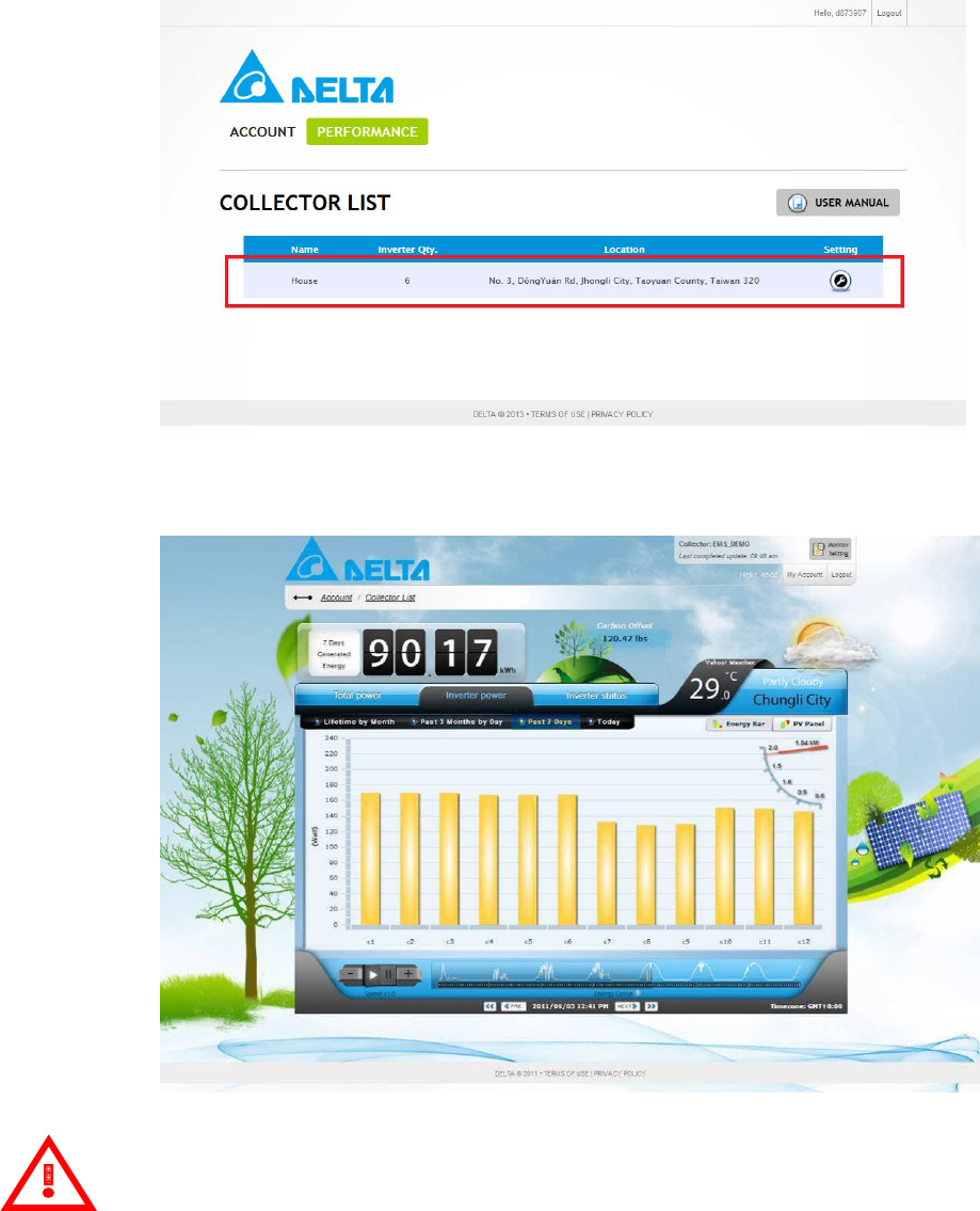
Step 14. After checking, you can scroll the lists to see the detail information of
all inverters from the website as shown below.
Step 15. You also can see the power data of the individual panel display by
different date types.
Attention
The best resolution is 1024x768.
The browsers are below:
Google Chrome
Firefox 4.0+
Internet Explorer 8.0+
Safari 5.0+
Opera 11+
29
Monitor with no Internet
Step 1. Please select the DELTA_XXXXXXXXXXXX and connect to it after the
system startup. X is Wi-Fi MAC address.
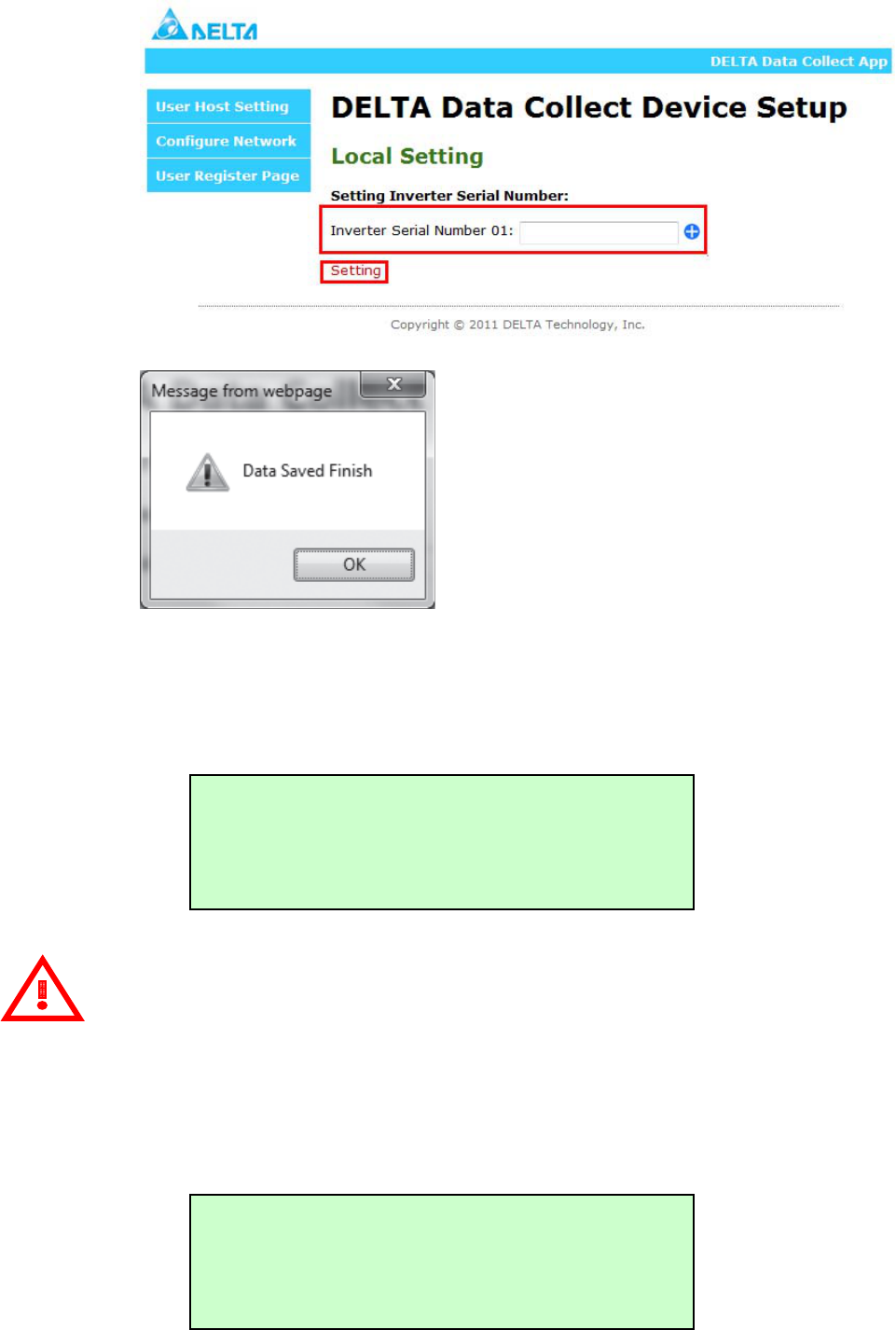
Step 2. Press 169.254.0.1 on your notebook (or computer) with Wi-Fi or
ETHERNET function to connect device. Then choice the “User Register
Page”.
Step 3. Keying your inverter serial number in this page. You can press “+” to
increase and “-” to decrease the inverter number. Press “Setting” if you
set it finish. And please repeat step 3 and step 4 again if you set fail.
30
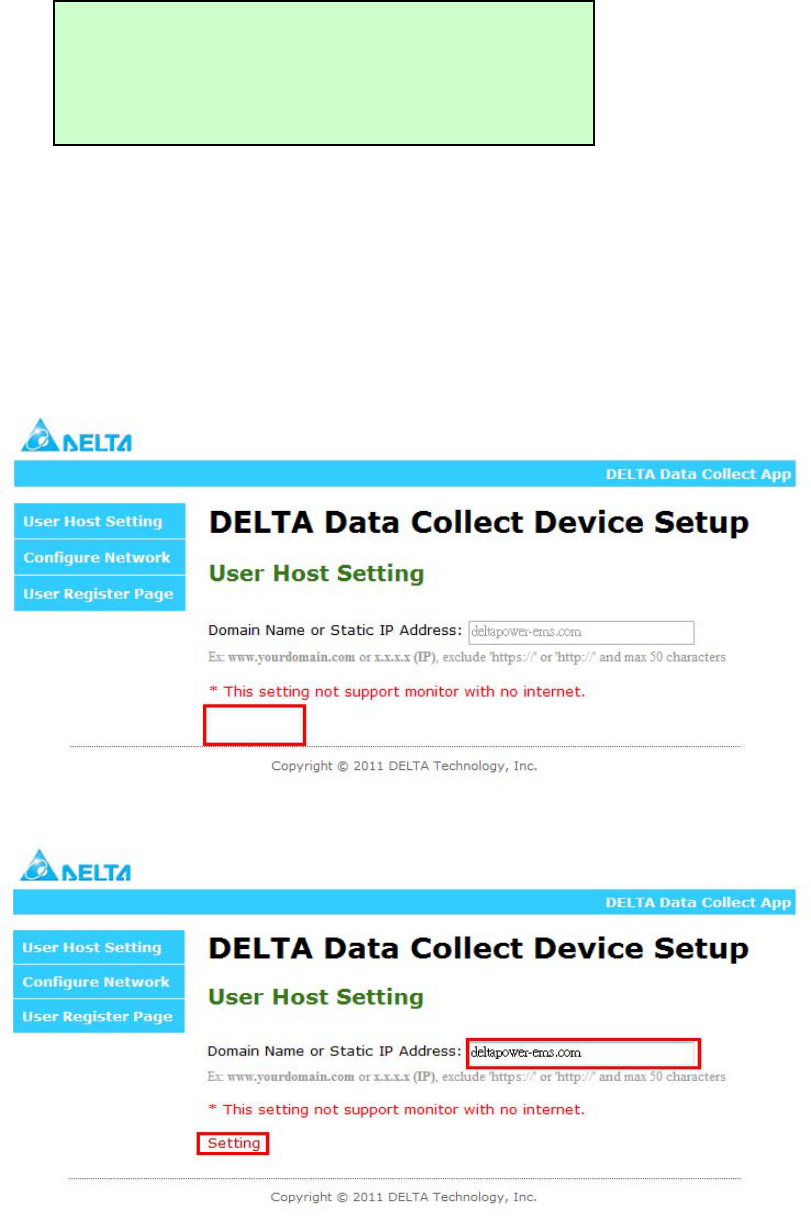
Step 4. After pressing the “SETTING”, you can see the message “PLEASE AWAIT
CONFIG” display on LCD. The time count is depending on your PV micro
inverter numbers to connect with DDP. The power information displays
after time counting finishes.
Attention
The DDP connects with PV micro inverters by using the power line
communication (PLC) method. It takes some times to connect, but it doesn’t
connect successful because the PLC can’t verify success. So, it will display two
statuses as bellow if time count has finished.
Status 1: It connects successful if LCD displays the power information after few
minutes.
PLEASE AWAIT CONFIG
XX:XX
169.254.0.1
ID: 1 POWER:123.4W
31
Status 2: It connects fail if LCD doesn’t display power information. For this status,
it needs to spend some time to connect again until it connects
successful. Please kindly inform our service if it always can’t display
after half hour or above.
User Host with Connect to Internet
Step 1. Please refer the “Login and Register Screen with Connect to
Internet” session to follow from step 1 to step 4 if user select the WiFi
transmitter or reference
Step 2. It can modify the IP address or domain name by user if you follow the
step1. Otherwise, it will block if you don’t connect to internet.
Press the “Setting” if you key in finish. The default is our host.
169.254.0.1
ID: 1 POWER: W

32
Step 3. Then, please keep following the step 5 until finish all operations with
“Login and Register Screen with Connect to Internet” session.
Event Messages
The table below lists the all messages that the DDP can produce to indicate certain
conditions. These messages are displayed on our webpage and they can provide
Delta Customer Support with needed information, if you should call for assistance.
The Message Displayed:
LCD Status Indication EMS Status Description
0001 Input over voltage The PV Micro-Inverter detects
an input over-voltage event
0002 Input under voltage The PV Micro-Inverter detects
an input under-voltage event
0004 Input over current The PV Micro-Inverter detects
an input over-current event
0008 Output over voltage The PV Micro-Inverter detects
an output over-voltage event
0010 Output under voltage The PV Micro-Inverter detects
an output under-voltage event
0020 Output over current The PV Micro-Inverter detects
an output over-current event
0040 Output over frequency The PV Micro-Inverter detects
an output over-frequency event
0080 Output under frequency The PV Micro-Inverter detects
an output under-frequency
event
0100 Islanding effect The PV Micro-Inverter detects
an unintentional islanding
event
0200 Ground fault detection &
interruption The PV Micro-Inverter detects
a ground fault event
0400 Main point over
temperature The PV Micro-Inverter detects
an over-temperature event
from main thermal sensing
point
0800 Second point over
temperature The PV Micro-Inverter detects
an over-temperature event
33
from second thermal sensing
point
4000 Loss feedback message This data collector can’t
communicate with PV
micro-inverter
P.S: For example, if “Input over voltage” and “Output over current” happen
on the same time, the LCD status indication will display “0011”.
Attention
Please don’t dismantle the device or make any repairs if you are not installer or
qualified personnel. These error messages must perform by these personals. So, please call
these personals if you can’t solve error problems.
34
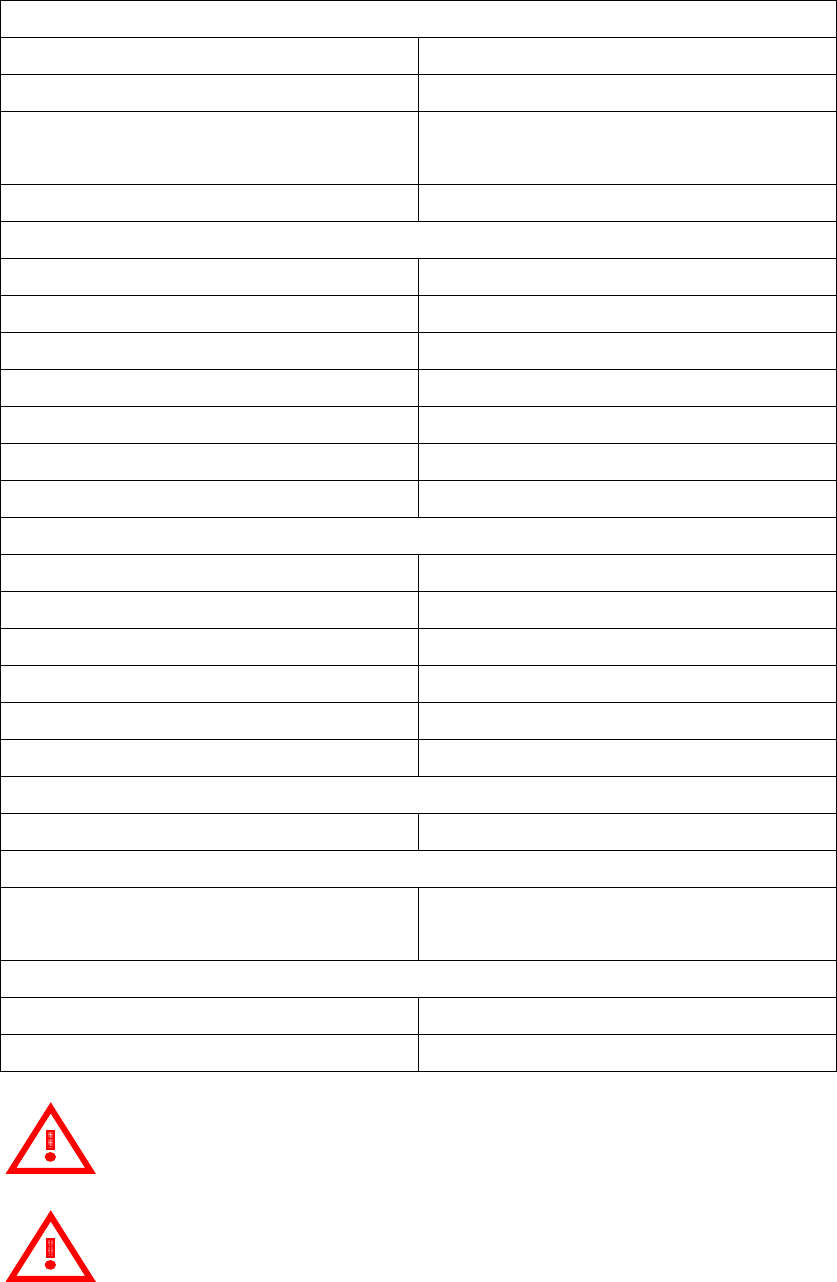
6. Technical Data
Communication Interface
Power Line Narrowband PLC Up to 28.8kbps
Ethernet 10/100BASE-T / IEEE 802.3™
Wi-Fi IEEE Std. 802.11b/g™ 2.4 GHz /
11/54 Mbps
DHCP Client Service Yes
AC Input Power Requirements
Minimum Input 90(Vrms)
Maximum Input 264 (Vrms)
Nominal Input 100-240(Vrms)
Minimum Input Frequency 47(Hz)
Maximum Input Frequency 62(Hz)
Nominal Input Frequency 50-60(Hz)
Input power (maximum) 6W
Mechanical Data
Outside Dimension (W x H x D) 172.4mm x 114.9mm x 31.2mm
Weight 700g +/-10g
Maximum operation altitudes Sea level 3000 m
Operating Temperature -10˚C to +40˚C
Cooling Natural convection – no fans
Enclosure Environment Rating Indoor - NEMA 1
Display
Two Columns OLED Display Yes
Safety and Standard
Compliance (Wi-Fi Module) IEC 60950-1, FCC Part 15 Class B
FCC Part 15, Subpart C
Reliability and Warranty
Warranty Period 1 year
Maximum PV micro Inverter 72pcs*
*Please kindly refer to Delta assembly manual of micro inverter to ensure you install correctly.
Attention
Delta reserves the right for specification change
Attention
For one data collector just can only set up these pieces at the single phase. If you
need to cross over the other phases, the PLC signal strength will have decay or interference
problems. It may be caused data loses symptoms.