Delta Electronics orporated DDP-A020003A Data Collector User Manual
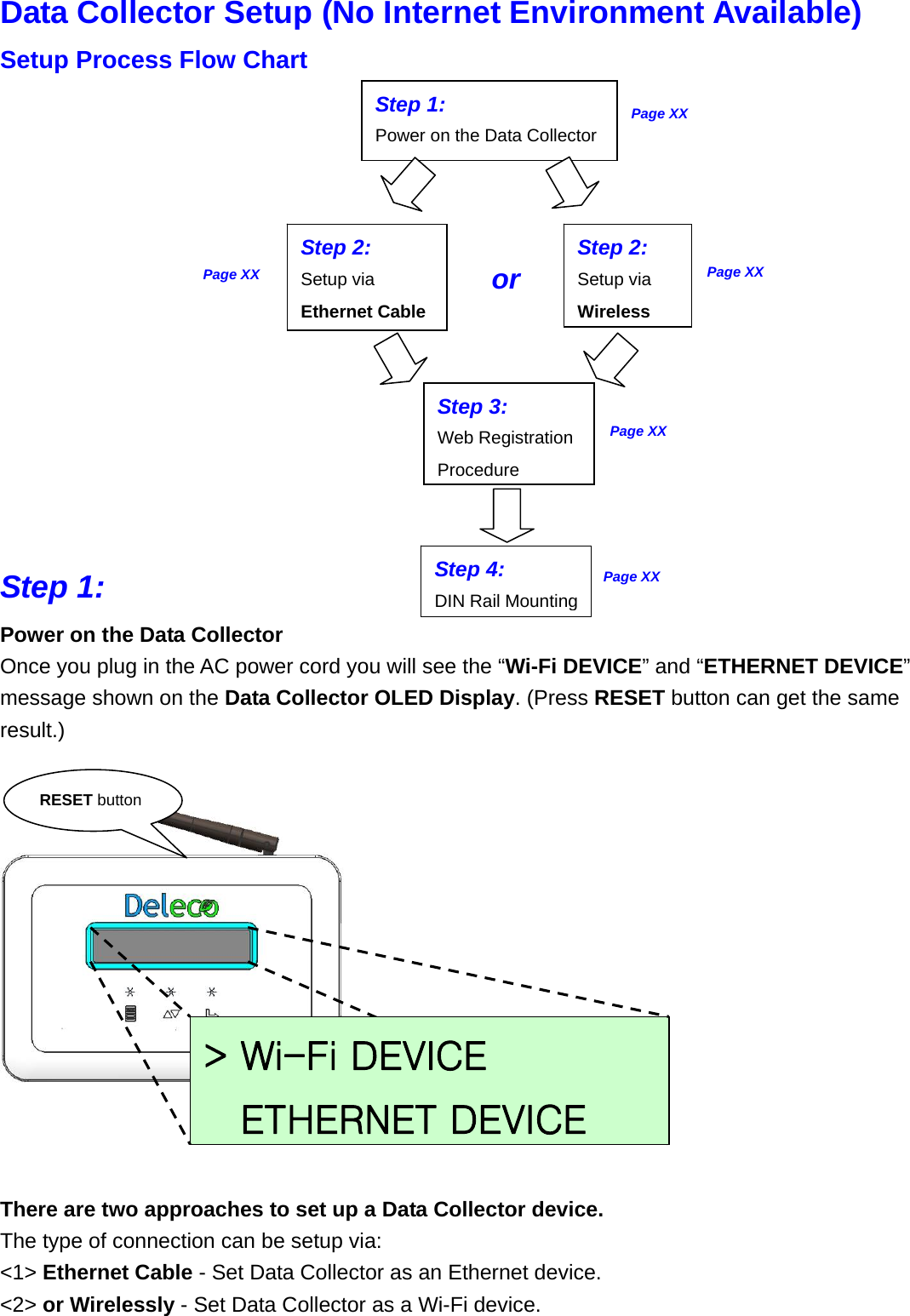
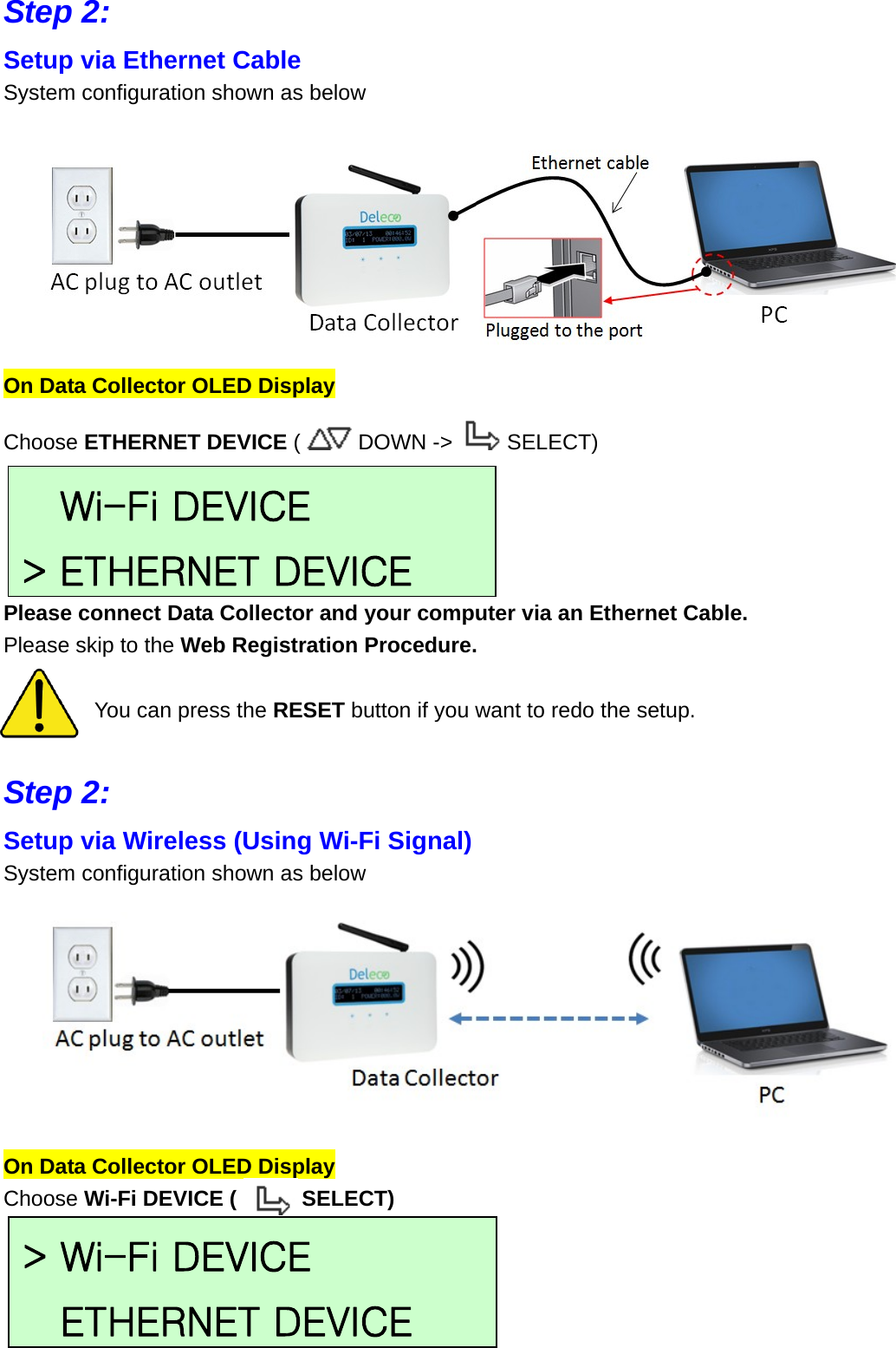
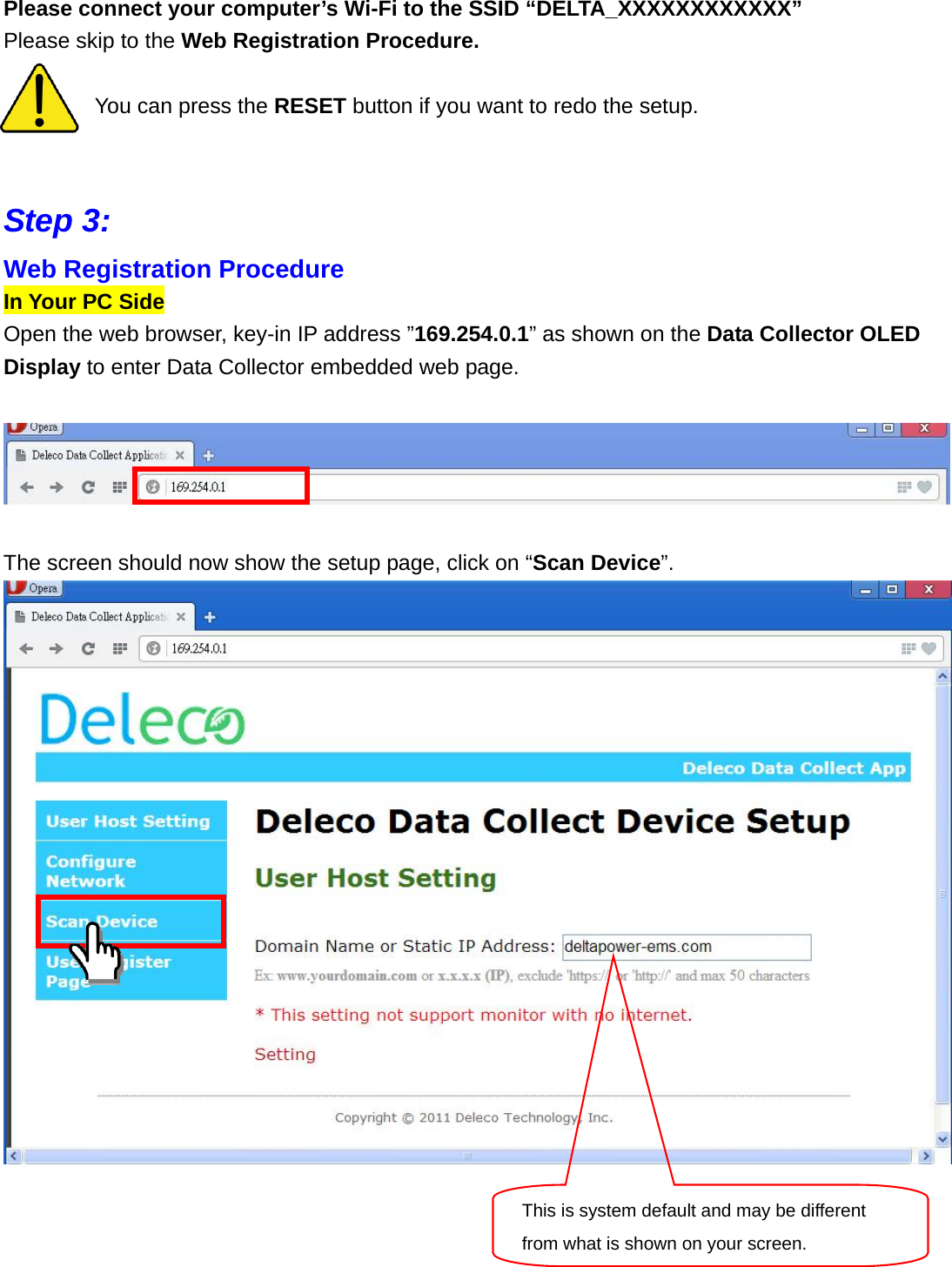
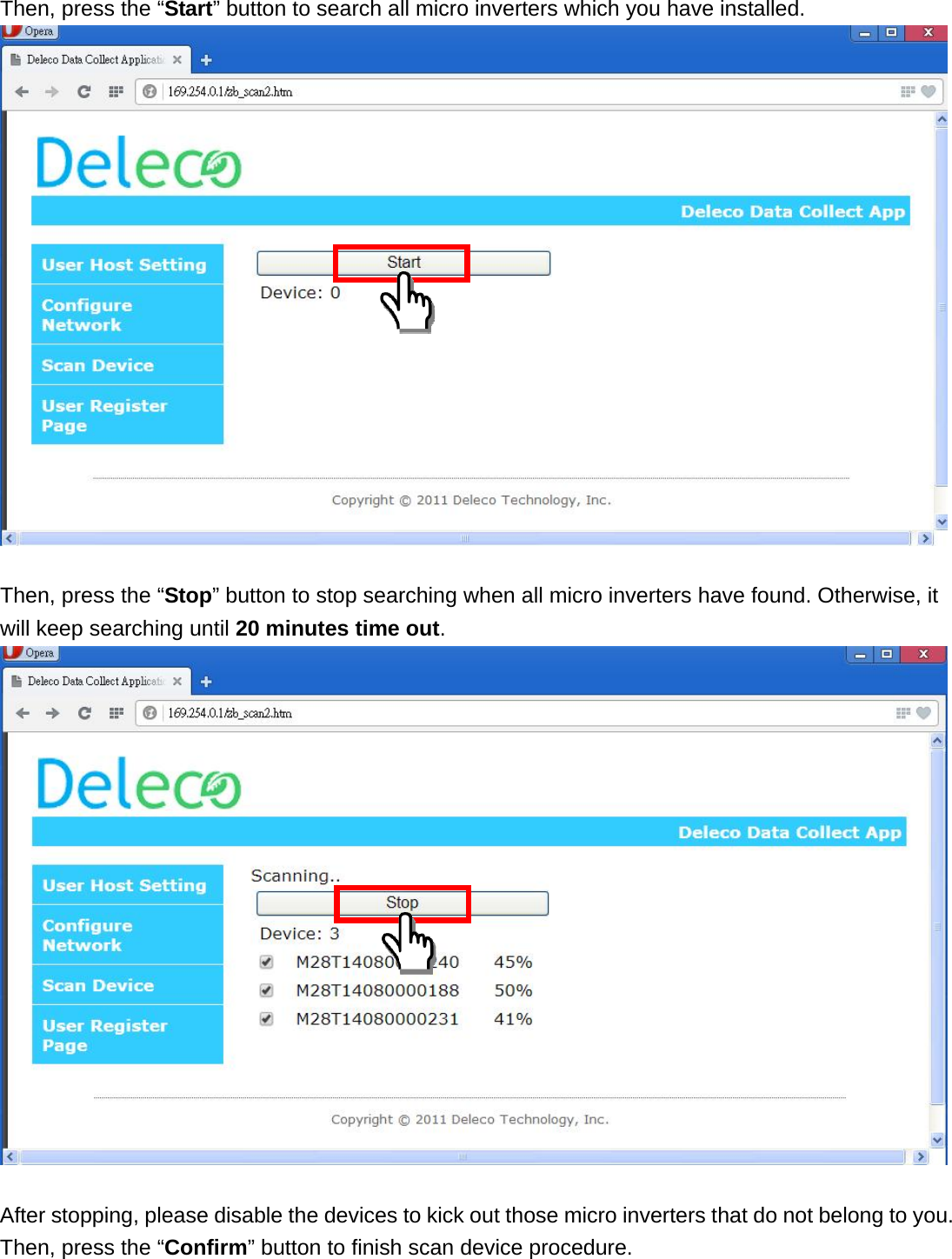
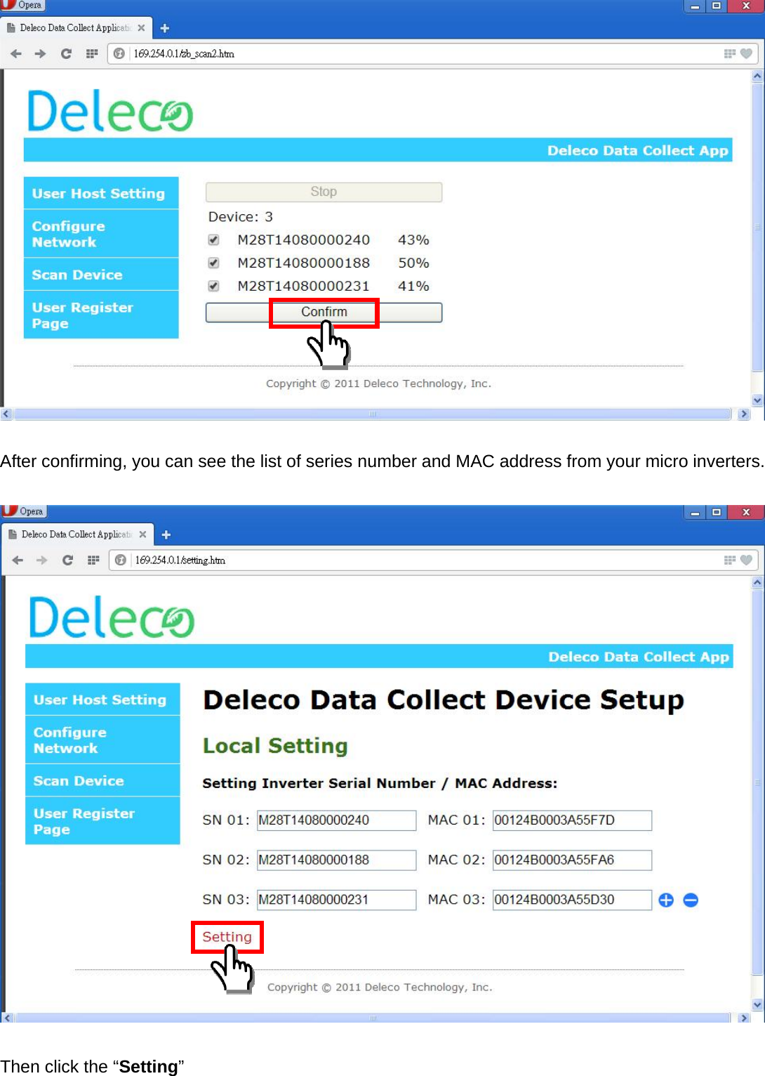
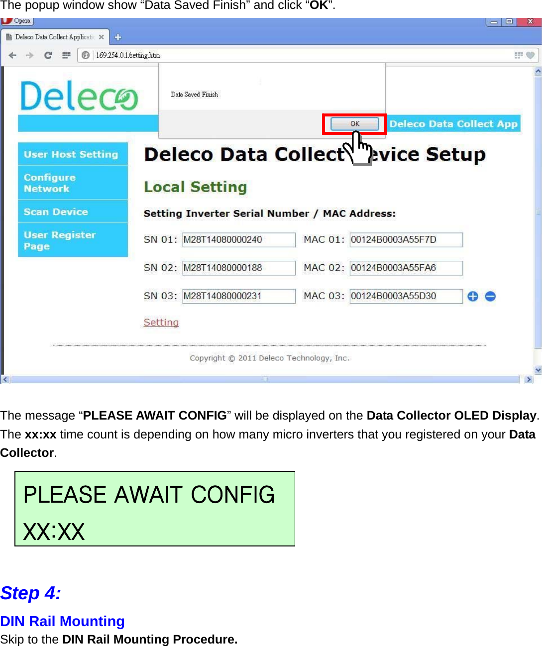
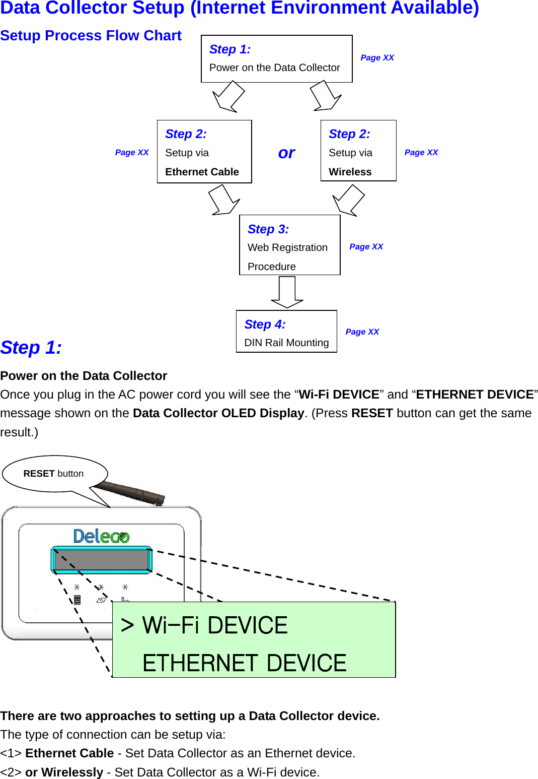
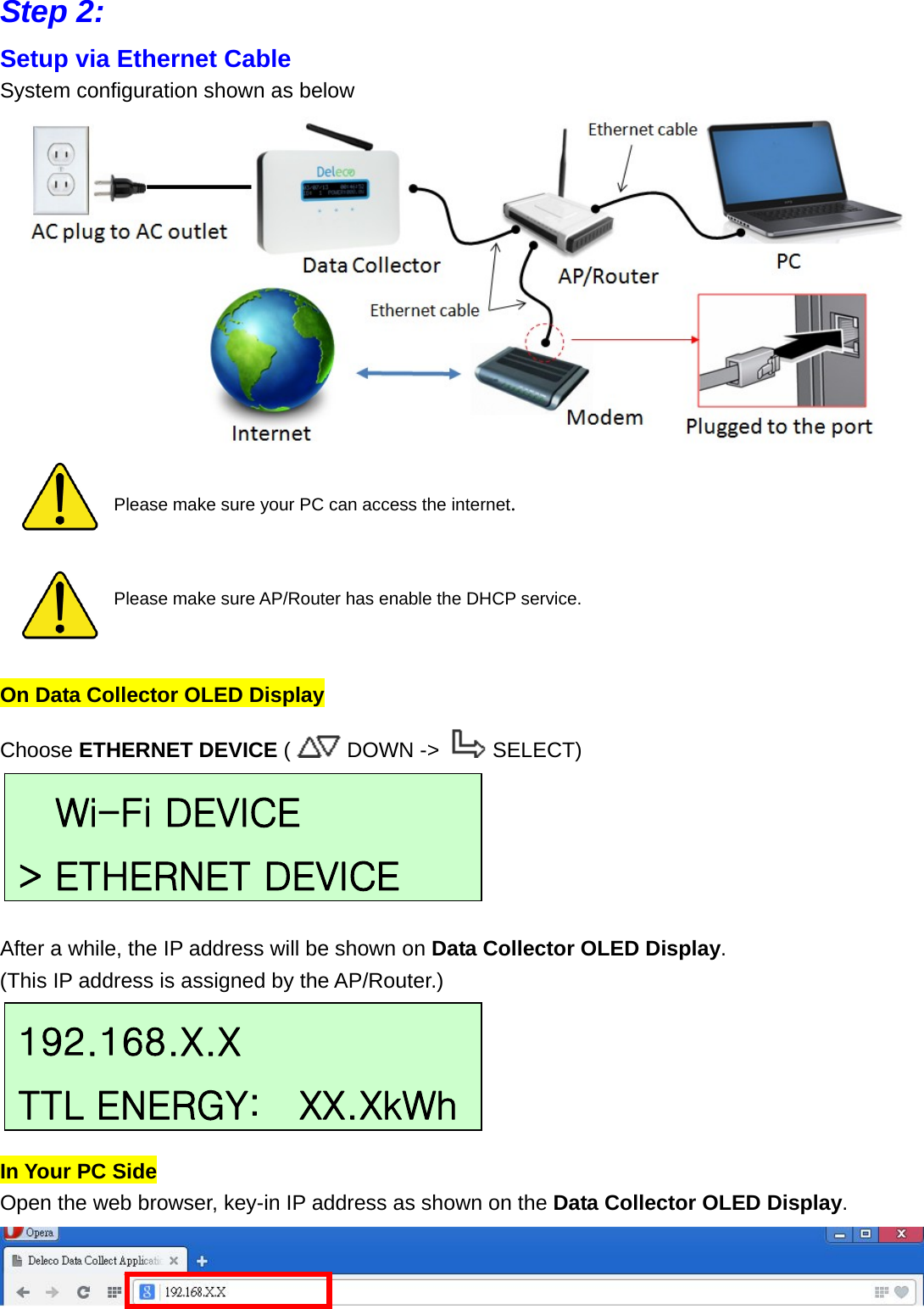
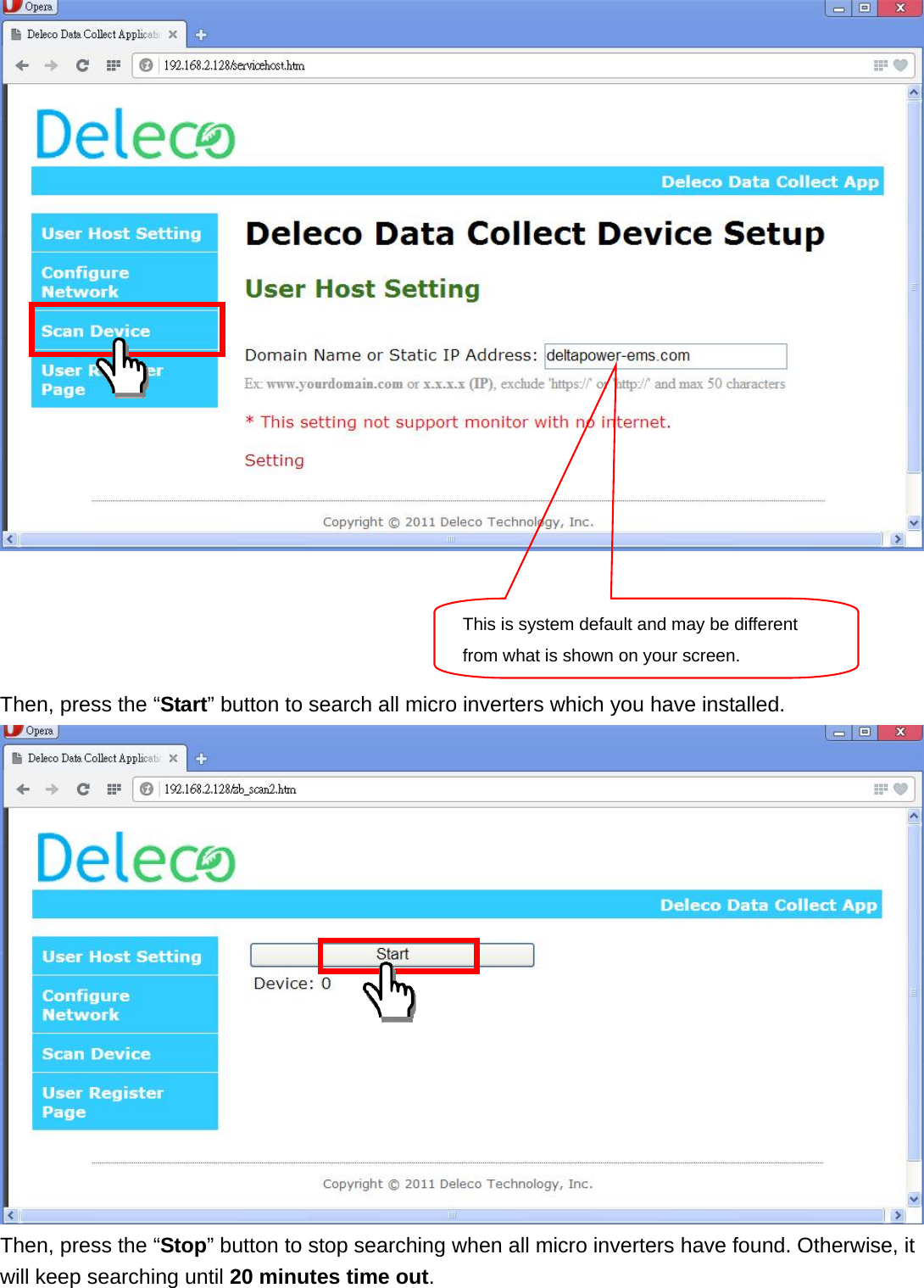
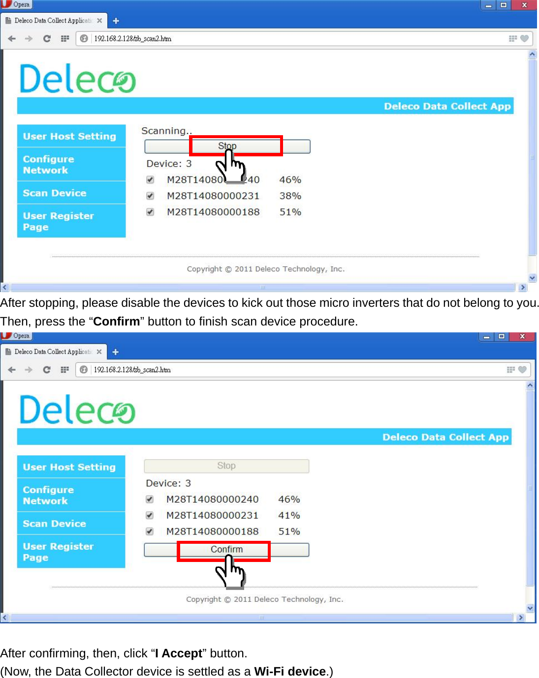
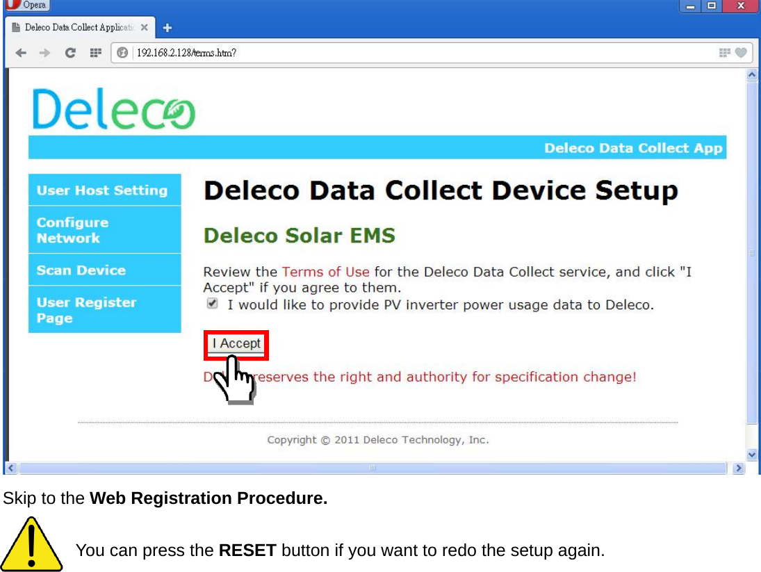
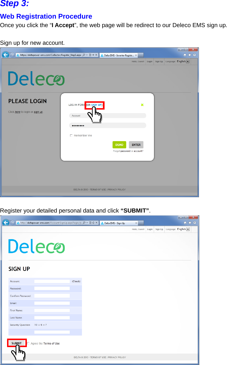
Delta Electronics Incorporated Data Collector
UserManual.wiki
>
Delta Electronics orporated
>
DDP A020003A User Manual
User Manual.pdf
Navigation menu
Upload a User Manual
Namespaces
Wiki Guide
HTML
PDF
Info
Views
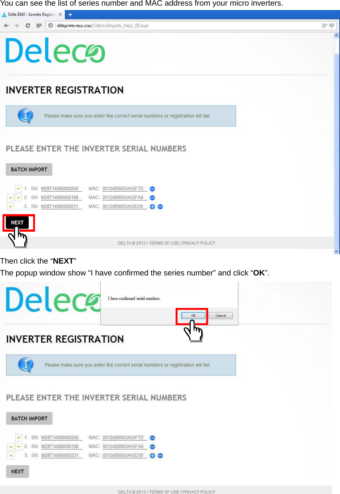
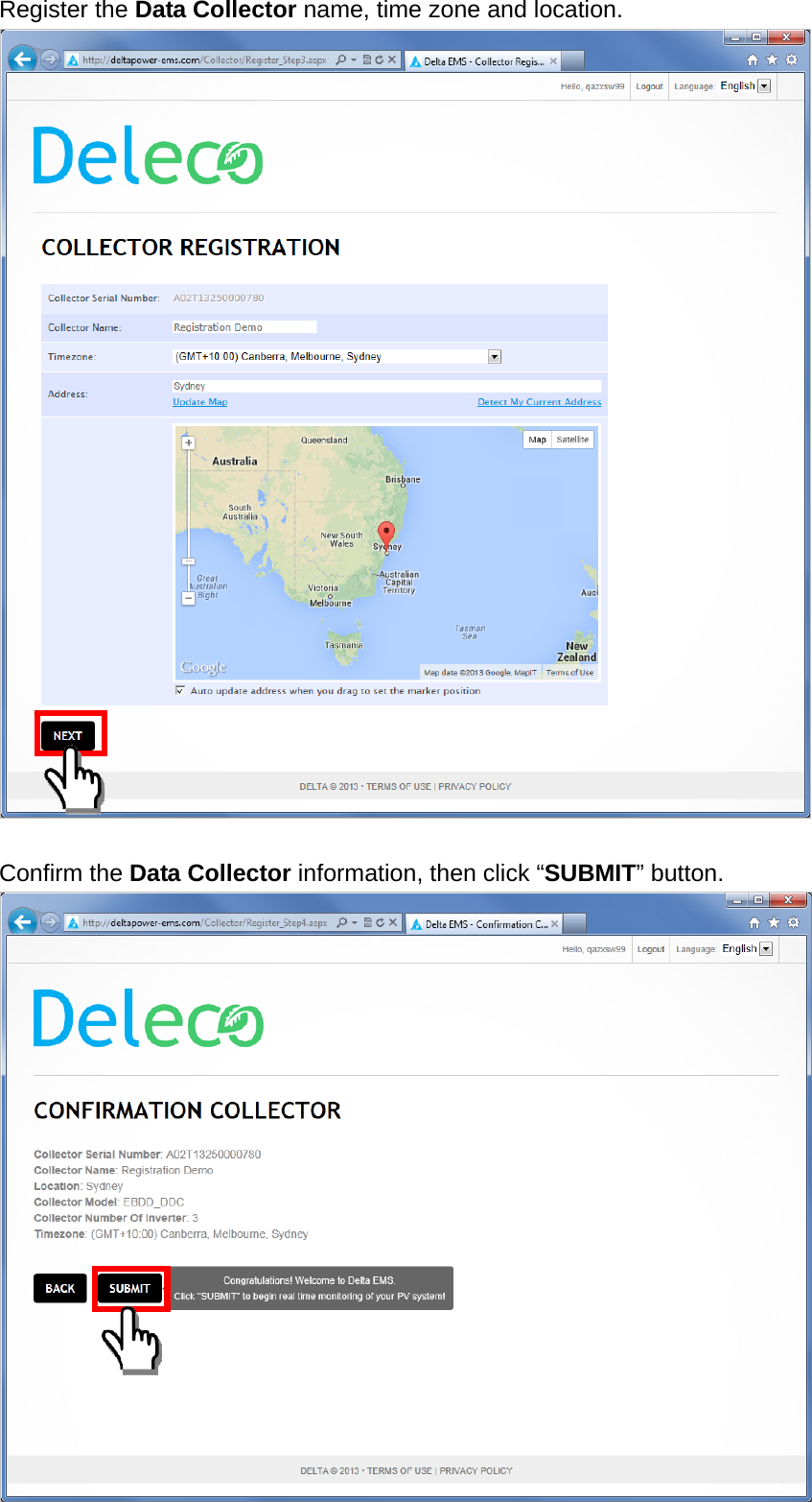
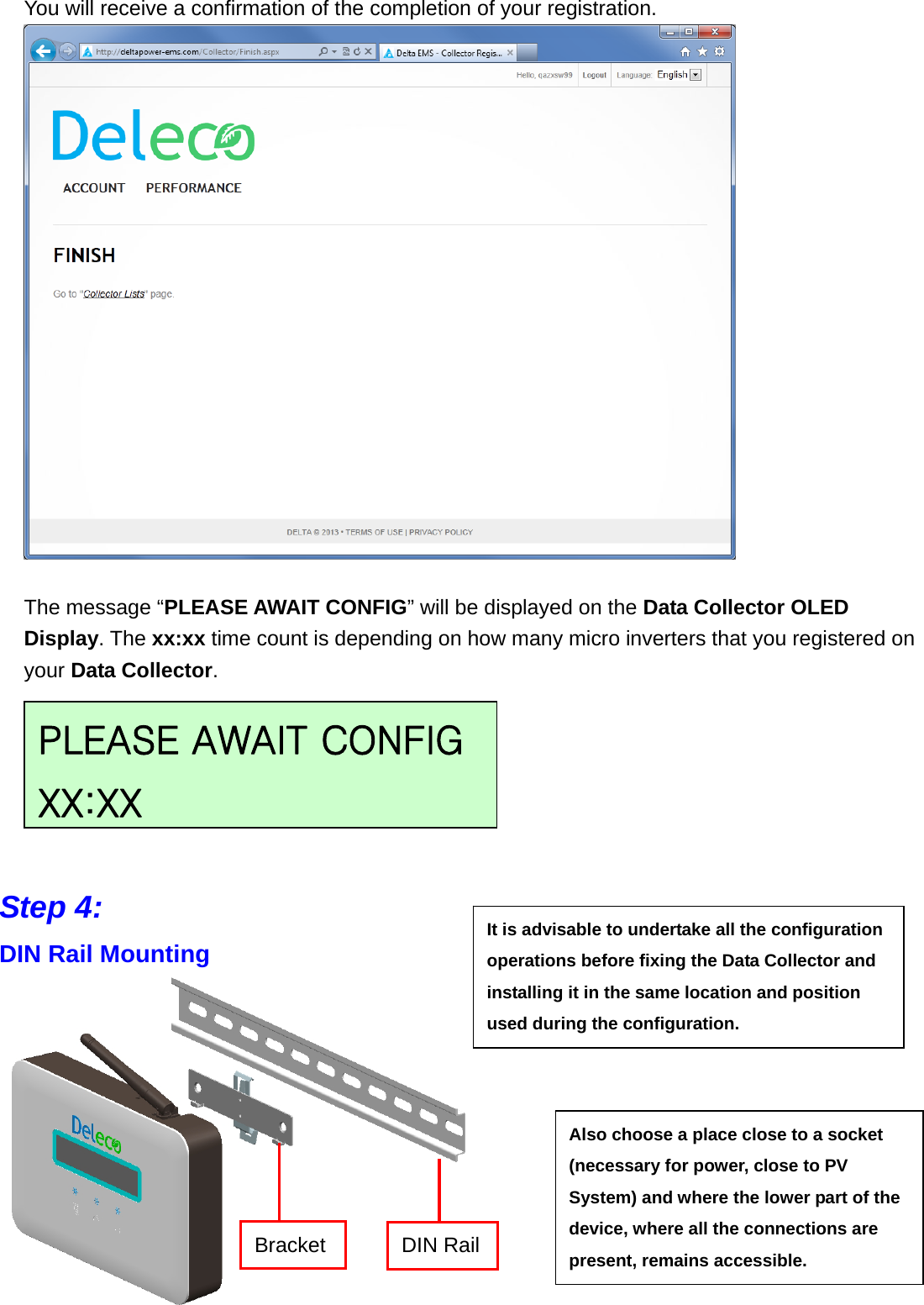
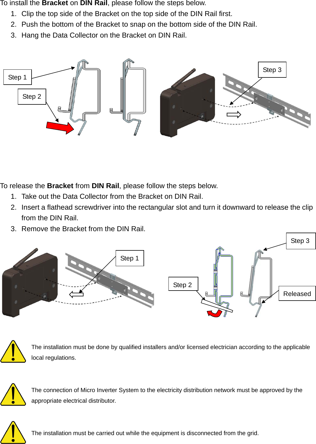
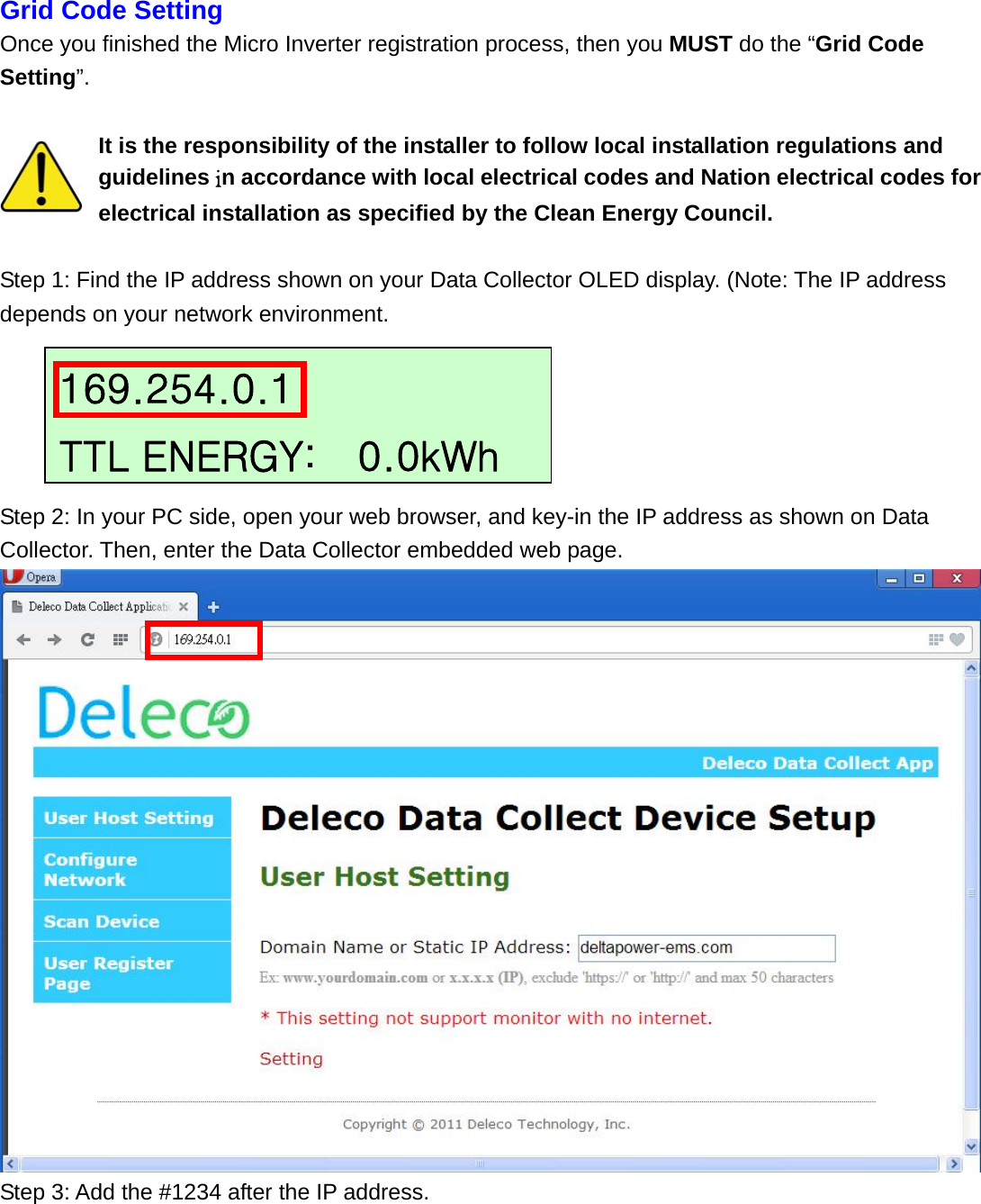
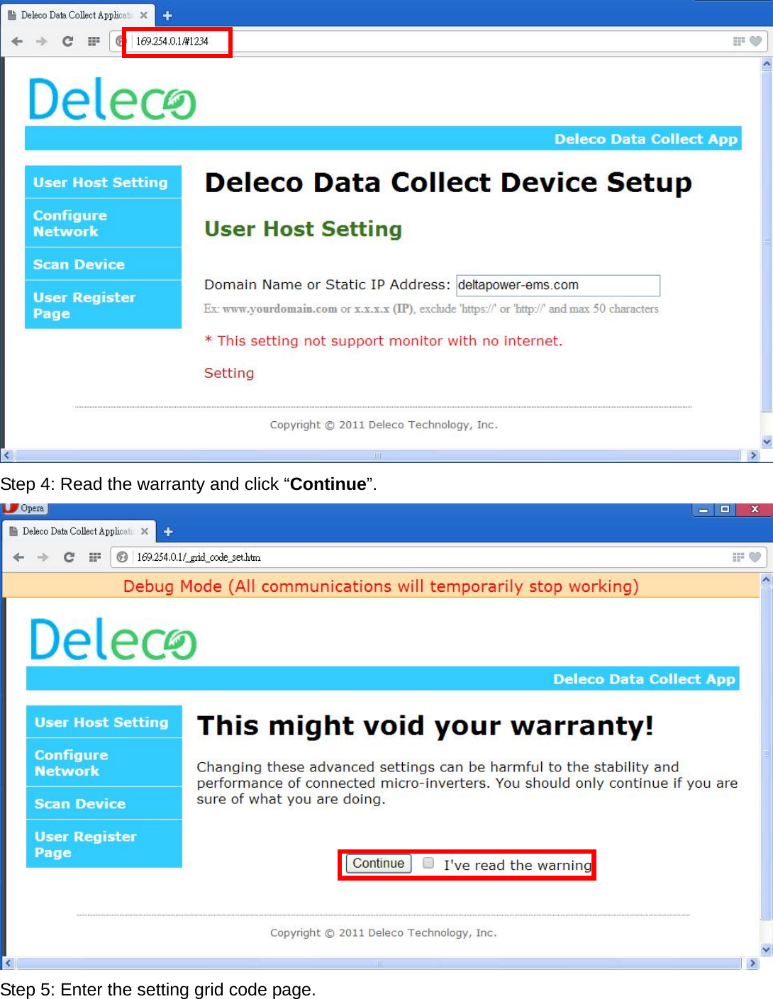
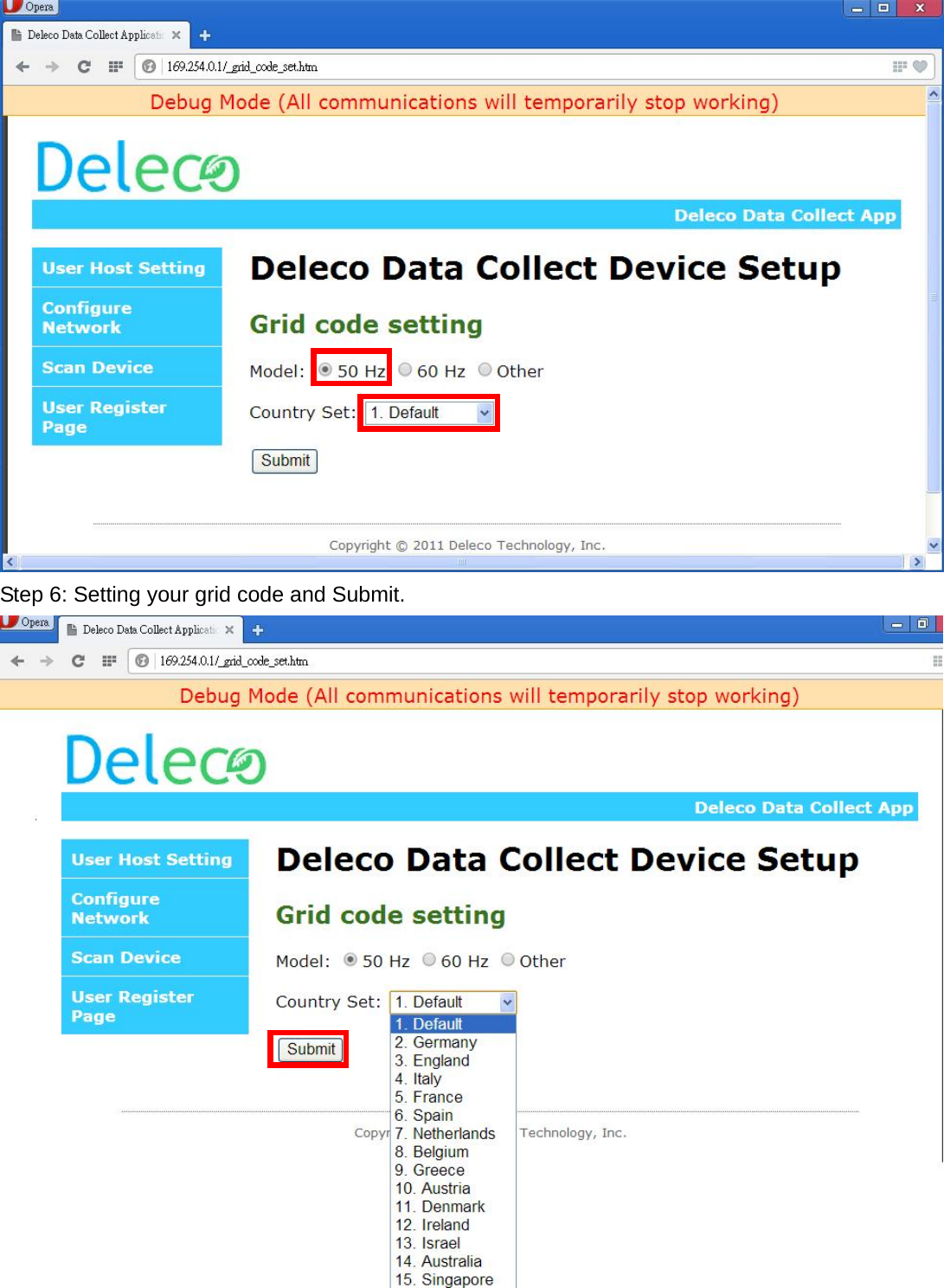
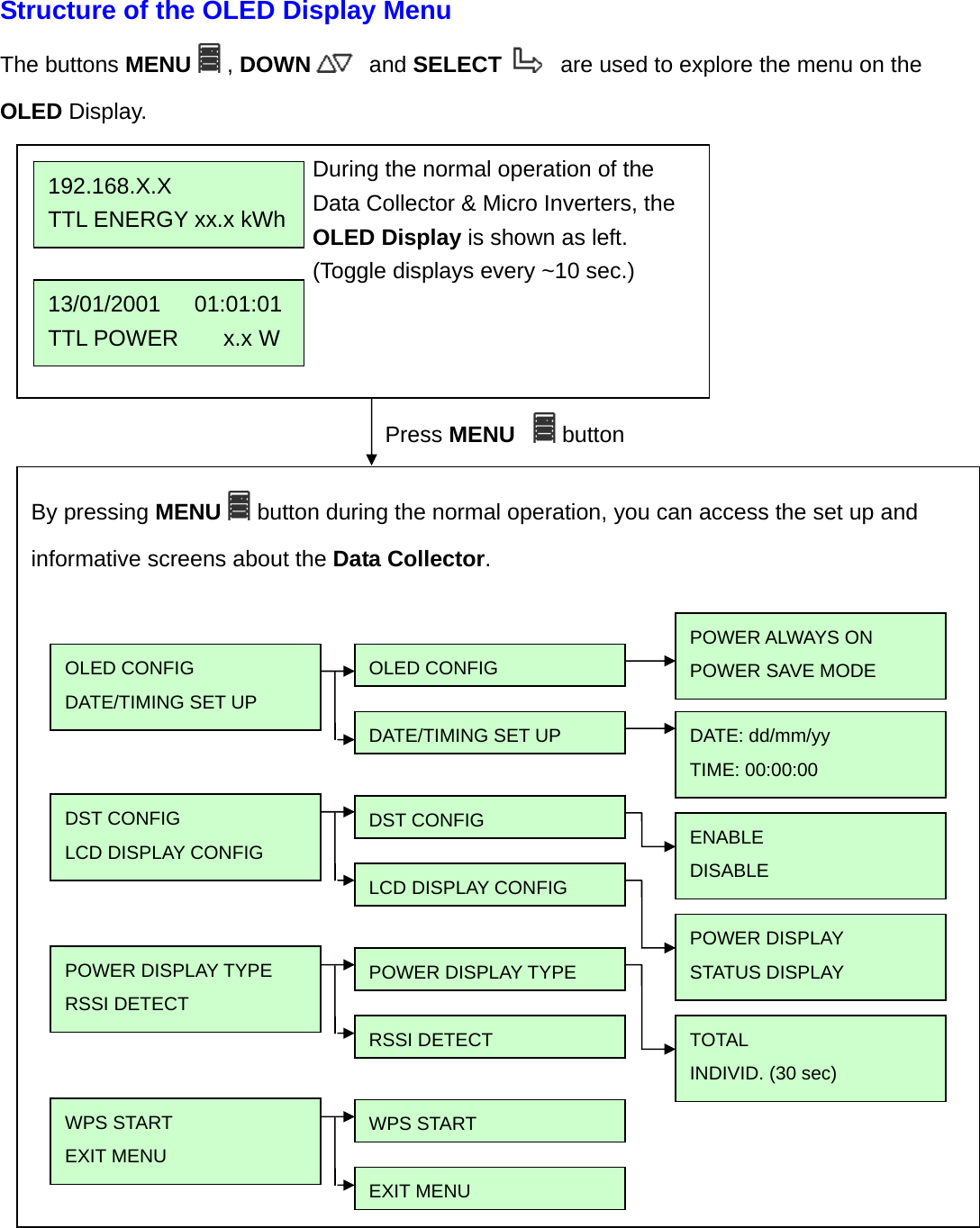
User Manual
Discussion / Help
Navigation