Delta Electronics orporated DDP-A020003A Data Collector User Manual
Delta Electronics Incorporated Data Collector
User Manual.pdf

QUICK SETUP GUIDE
Data Collector
Data Collector connects your PV Micro Inverter System to the internet in a simple quick way. It
uses ZigBee wireless radio frequency communication technology to monitor each micro inverter
without additional wiring. Through Web Portal, you can check data on the daily and historical
photovoltaic energy harvest.
Safety and Accident Prevention
The equipment has been manufactured in accordance with the strictest accident-prevention
regulations and supplied with safety devices suitable for the protection of components and
operators.
Deleco accepts no liability for failure to comply with the instructions for correct installation and cannot be
held responsible for the systems upstream or downstream of the equipment it has supplied.
It is essential to provide the operators with correct information. They must read and comply with the technical
information required in the manual and in the attached documentation.
The instructions given in this SETUP GUIDE does not replace the safety devices and technical data for installation and
operation stuck on the product, and they certainly do not replace the safety regulations in force in the country of
installation and common sense rules.
The manufacturer is willing to train staff, at its premises or on site, in accordance with conditions to be set out in the
contract.
Avoid temporary fixes. All repairs should be carried out using only genuine spare parts, which must be installed in
accordance with their intended use.
Liabilities arising from commercial components are delegated to the respective manufacturers.
The equipment must be installed indoors in rooms with suitable environmental conditions.
The equipment is not equipped to operate in environments that have particular flammable or explosive conditions.
In order to prevent signal collision in Micro Inverter Monitoring System, only ONE Data Collector installed
is permitted. (More than TWO Data Collectors installed in Micro Inverter System could cause signal
collision problem!), and up to 32 micro inverters can be directly monitored by a single Data Collector.
There is a hazard voltage inside this equipment and no maintainable parts inside this equipment.
Do not use the equipment if you find any anomalies while it is operating.
Federal Communication Commission Interference Statement
This device complies Part 15 of the FCC Rules. Operation is subject to the following two
conditions: (1) This device may not cause harmful interference, and (2) this device must
accept interference received, including interference that may cause undesired
operation.
This equipment has been tested and found to comply with the limits for a Class B digital
device, pursuant to part 15 of the FCC Rules. These limits are designed to provide
reasonable protection against harmful interference in a residential installation. This
equipment generates, uses and can radiate radio frequency energy and, if not installed
and used in accordance with the instructions, may cause harmful interference to radio
communications. However, there is no guarantee that interference will not occur in a
particular installation. If this equipment does cause harmful interference to radio or
television reception, which can be determined by turning the equipment off and on, the
user is encouraged to try to correct the interference by one of the following measures:
z Reorient or relocate the receiving antenna.
z Increase the separation between the equipment and the receiver.
z Connect the equipment into an outlet on a circuit different from that to which the
receiver is connected.
z Consult the dealer or an experienced radio/TV technician for help.
FCC Caution: Any changes or modifications not expressly approved by the party
responsible for compliance could void the user's authority to operate this equipment.
This transmitter must not be co-located or operating in conjunction with any other
antenna or transmitter.
Radiation Exposure Statement:
This equipment complies with FCC radiation exposure limits set forth for an uncontrolled
environment. This equipment should be installed and operated with minimum distance
20cm between the radiator & your body.
Note: The country code selection is for non-US model only and is not available to all US
model. Per FCC regulation, all WiFi product marketed in US must fixed to US operation
channels only.
Pursuant to IEC60950, the Data Collector involves technologies and materials or
methods provide a level of safety.
Any modifications or changes made to this equipment may void the user warranty.
Overview
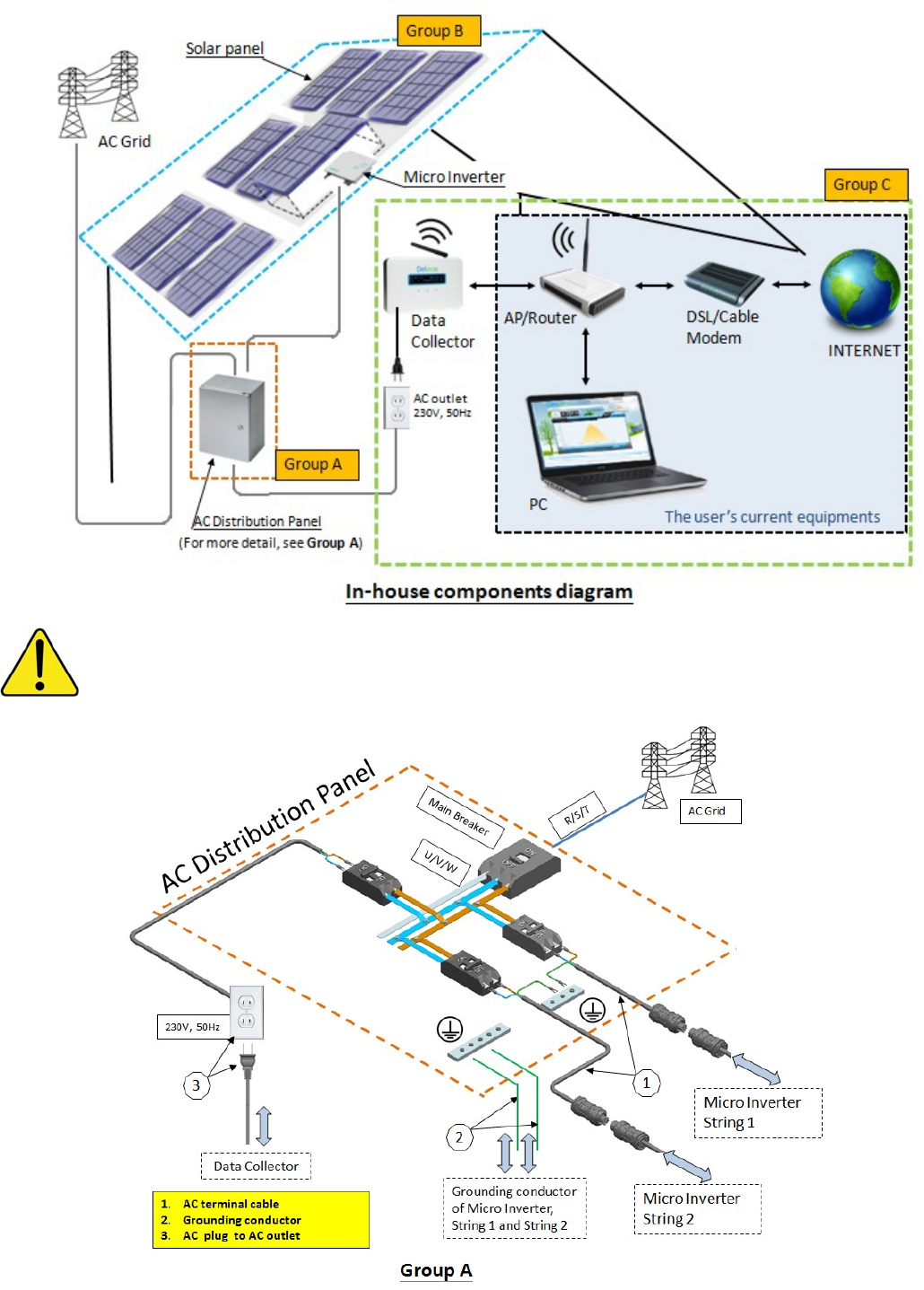
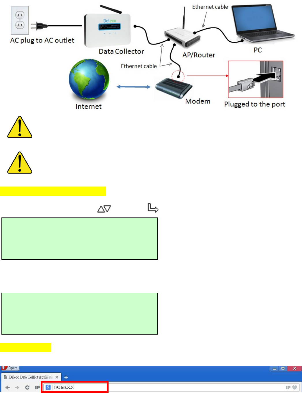
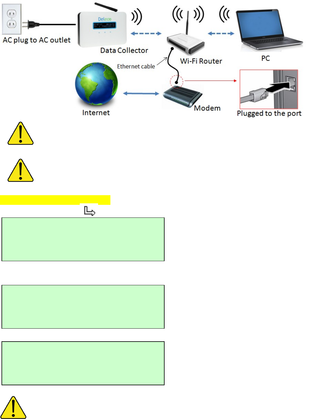
This diagram shows the relationship between Data Collector and other devices.
For Micro Inverter Monitoring System, the Data Collector communicates with your Micro Inverter System
via wireless, the communication quality is depended on your actual installation environment. (The
shortest distance between Data Collector and Micro Inverters is preferred!)
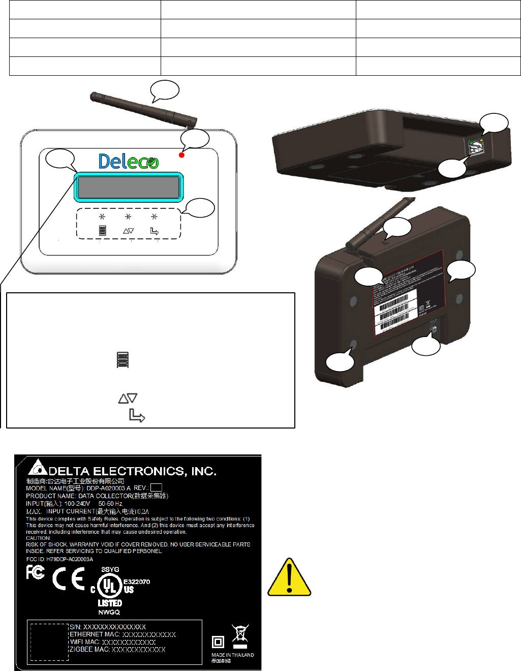
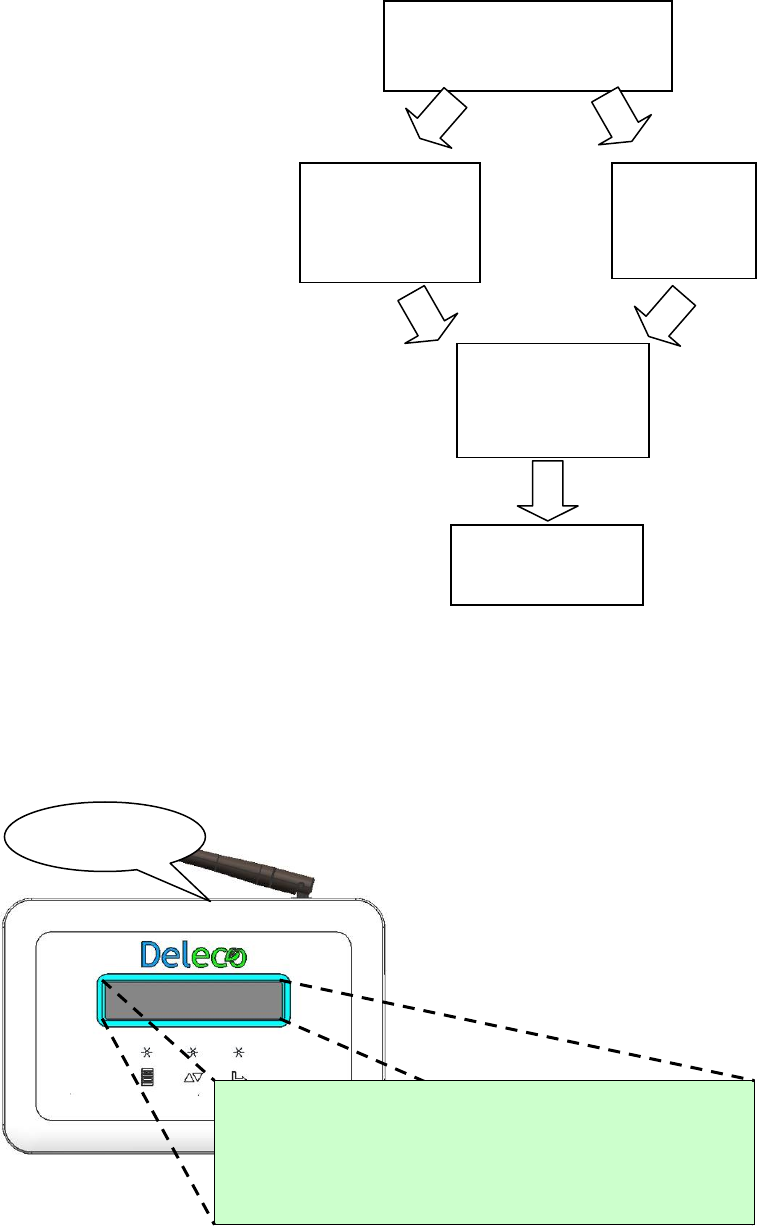
Data Collector Key Parts Description
01: ZigBee antenna 02: Status LED (under the plastic cover) 03: OLED Display
04: Keypad (touch pad) 05: Ethernet port 06: Ethernet status LED
07: RESET button 08: AC inlet 09: Wall mount holes
10, Spec. Label 11: Rubber foots
Data Collector Serial Number
ETHERNET communication MAC address
Wi-Fi communication MAC address
ZigBee MAC address
The Spec. Label attached to the Data Collector
must not be removed, damaged or dirtied, etc.
The technical data shown in this manual does not in
any case replace those shown on the Spec. Label attached to
the Data Collector.
05
06
07
08
09
10
11
02
01
03
04
Keypad Description
There are 3 touch pads (Keypad) provide the various
functionalities.
The MENU button : shows menu and returns to
previous sub-menu when navigating.
The DOWN button : moves cursor down.
The SELECT button : similar to enter.
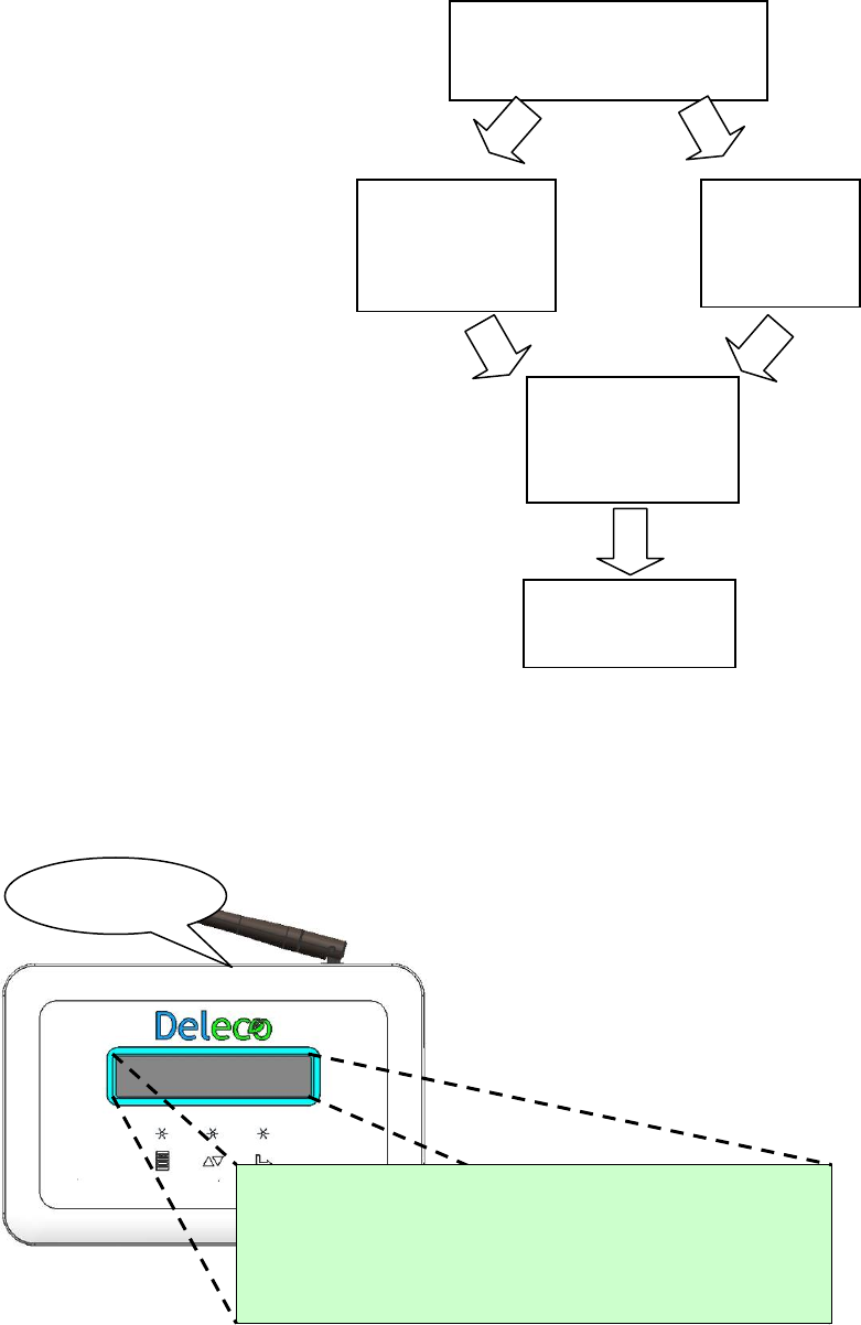
Data Collector Setup (No Internet Environment Available)
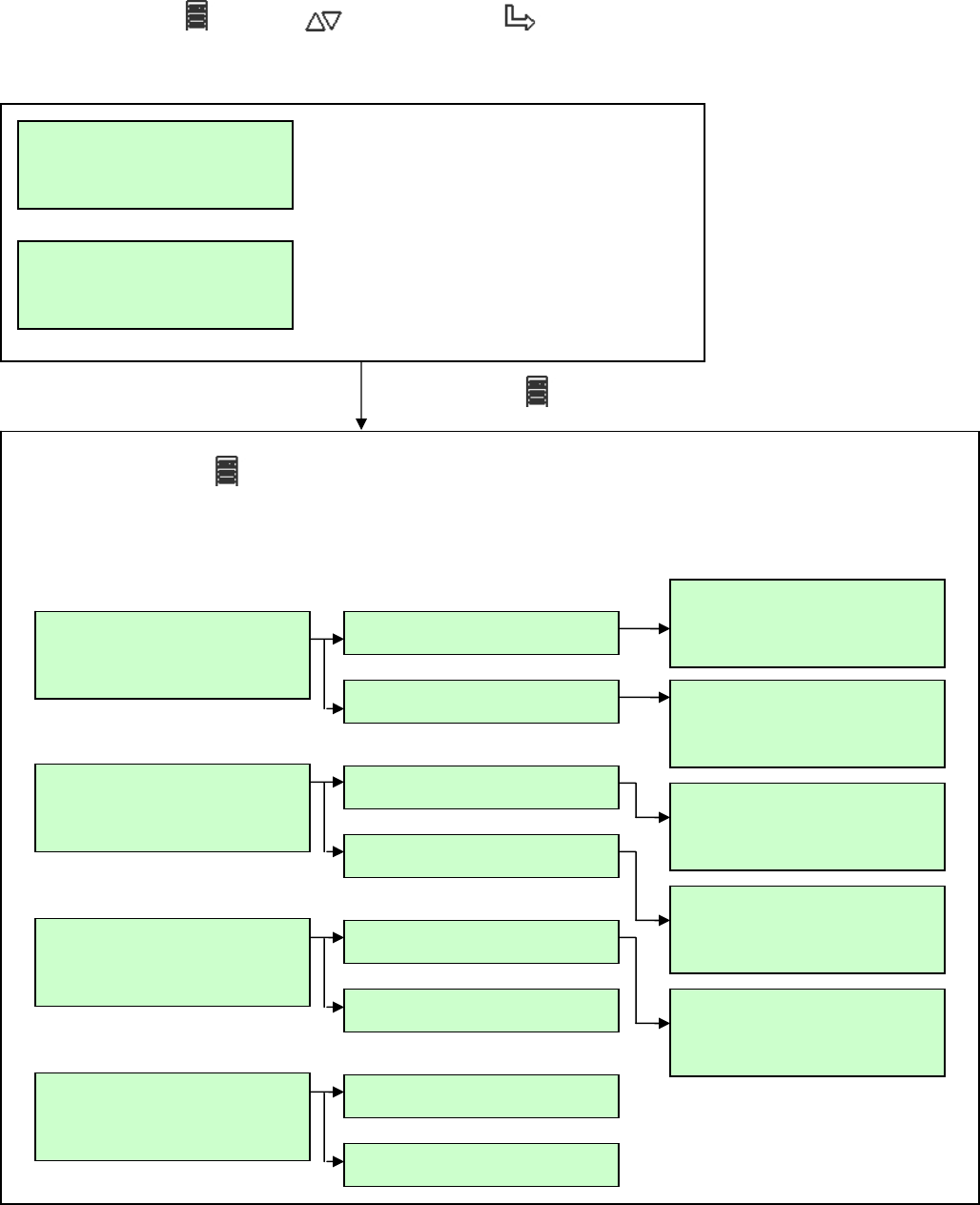
Setup Process Flow Chart
Step 1:
Power on the Data Collector
Once you plug in the AC power cord you will see the “Wi-Fi DEVICE” and “ETHERNET DEVICE”
message shown on the Data Collector OLED Display. (Press RESET button can get the same
result.)
There are two approaches to set up a Data Collector device.
The type of connection can be setup via:
<1> Ethernet Cable - Set Data Collector as an Ethernet device.
<2> or Wirelessly - Set Data Collector as a Wi-Fi device.
Step 1:
Power on the Data Collector
Step 2:
Setup via
Ethernet Cable
Step 2:
Setup via
Wireless
Step 3:
Web Registration
Procedure
or
> Wi-Fi DEVICE
> ETHERNET DEVICE
RESET button
Step 4:
DIN Rail Mountin
g
Page XX
Page XX
Page XX
Page XX
Page XX
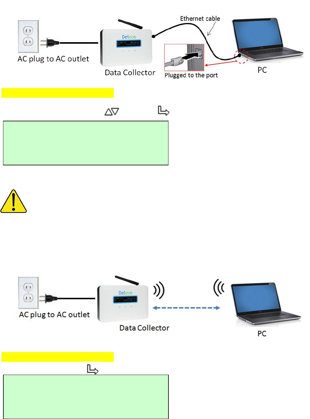
Step 2:
Setup via Ethernet Cable
System configuration shown as below
On Data Collector OLED Display
Choose ETHERNET DEVICE ( DOWN -> SELECT)
Please connect Data Collector and your computer via an Ethernet Cable.
Please skip to the Web Registration Procedure.
You can press the RESET button if you want to redo the setup.
Step 2:
Setup via Wireless (Using Wi-Fi Signal)
System configuration shown as below
On Data Collector OLED Display
Choose Wi-Fi DEVICE ( SELECT)
> Wi-Fi DEVICE
> ETHERNET DEVICE
> Wi-Fi DEVICE
> ETHERNET DEVICE
Please connect your computer’s Wi-Fi to the SSID “DELTA_XXXXXXXXXXXX”
Please skip to the Web Registration Procedure.
You can press the RESET button if you want to redo the setup.
Step 3:
Web Registration Procedure
In Your PC Side
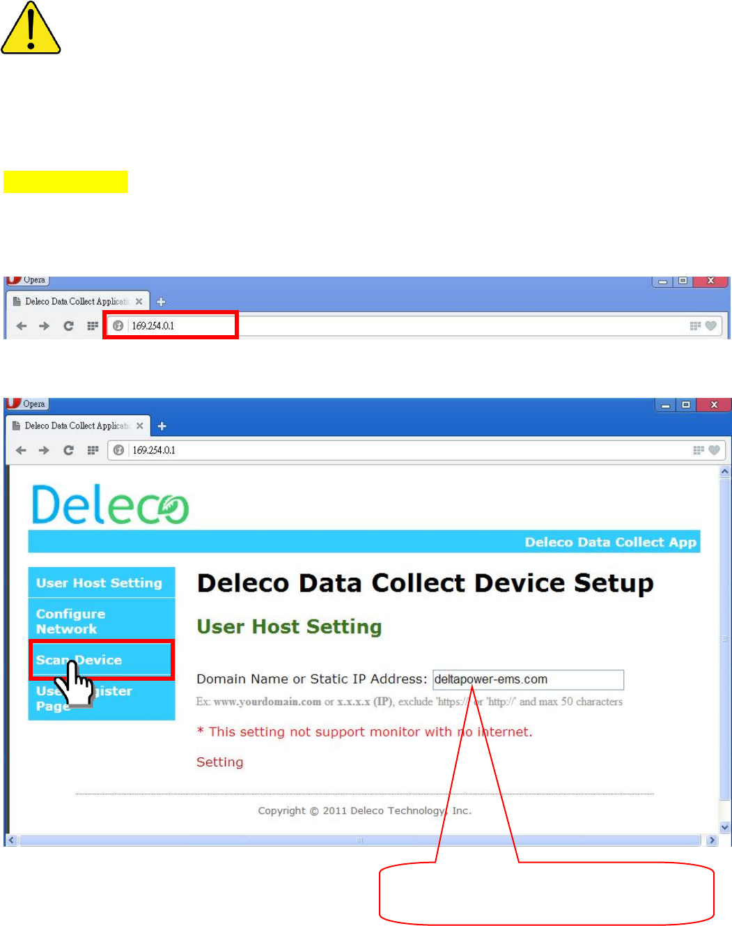
Open the web browser, key-in IP address ”169.254.0.1” as shown on the Data Collector OLED
Display to enter Data Collector embedded web page.
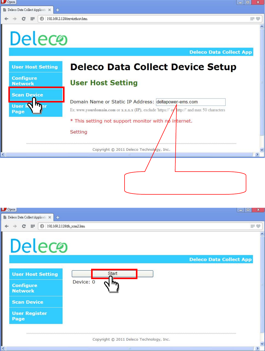
The screen should now show the setup page, click on “Scan Device”.
This is system default and may be different
from what is shown on your screen.
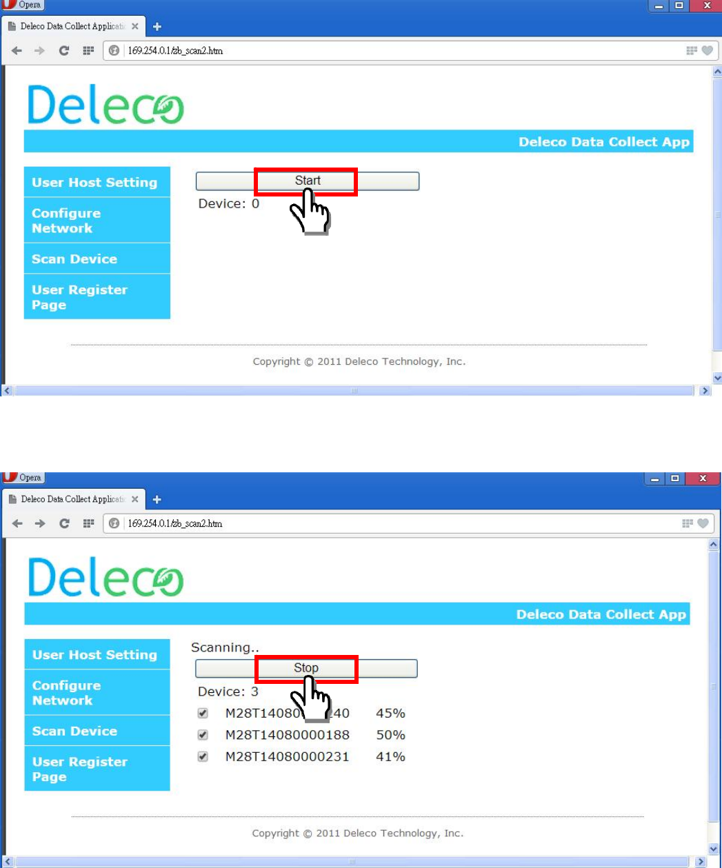
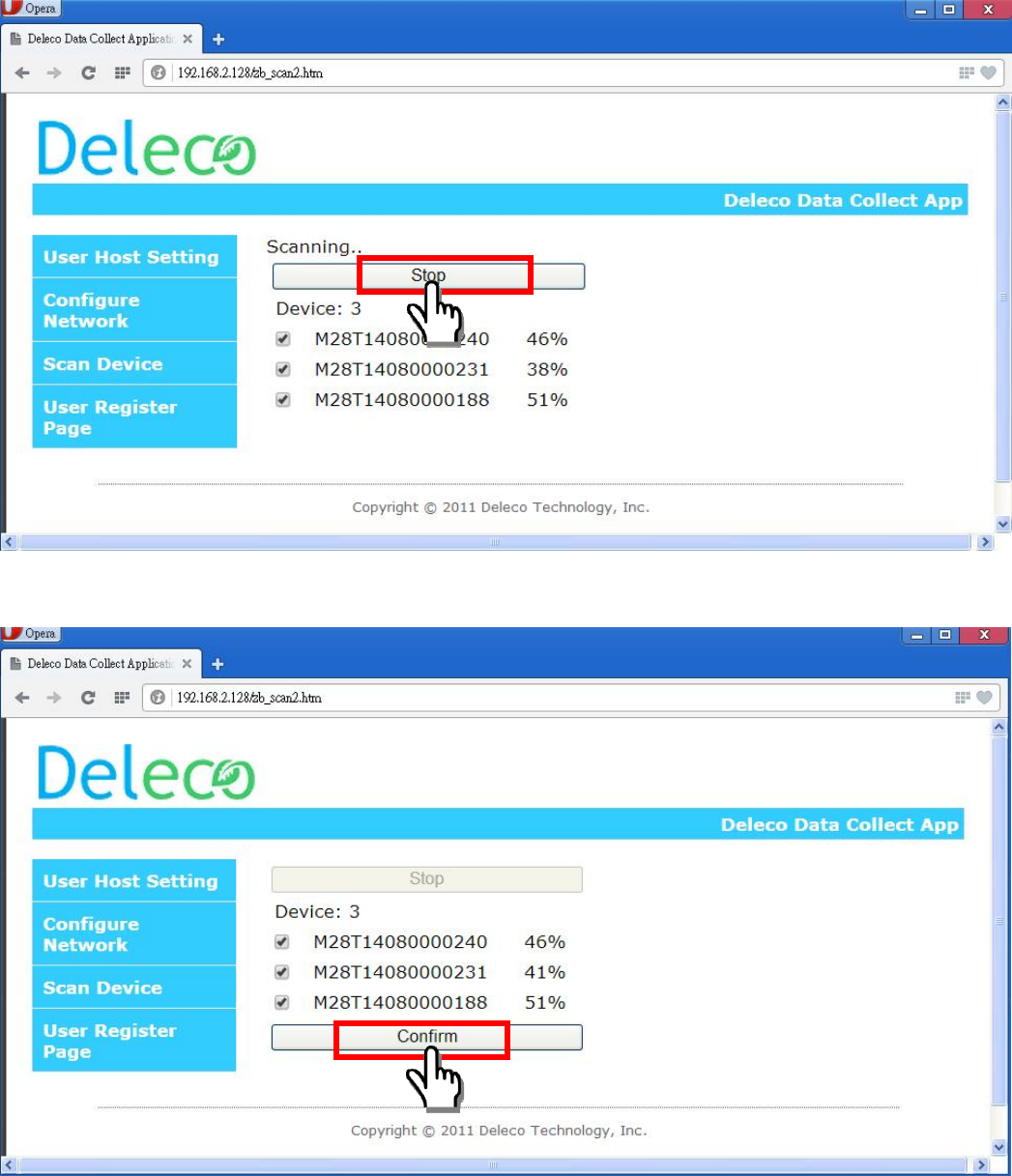
Then, press the “Start” button to search all micro inverters which you have installed.
Then, press the “Stop” button to stop searching when all micro inverters have found. Otherwise, it
will keep searching until 20 minutes time out.
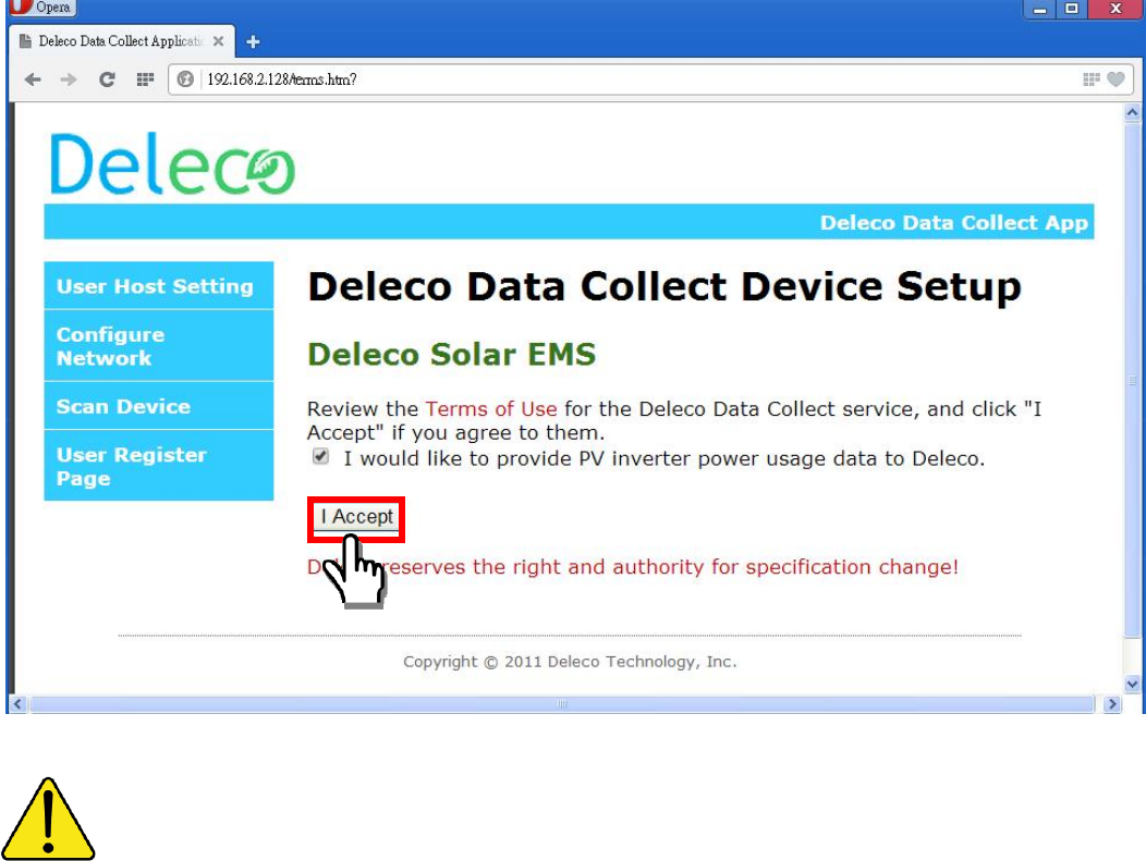
After stopping, please disable the devices to kick out those micro inverters that do not belong to you.
Then, press the “Confirm” button to finish scan device procedure.
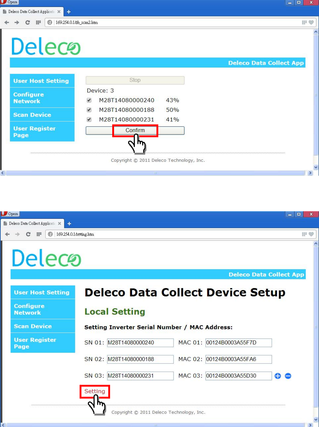
After confirming, you can see the list of series number and MAC address from your micro inverters.
Then click the “Setting”
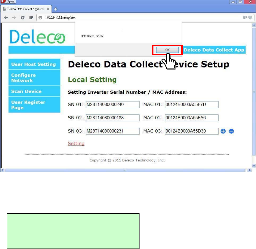
The popup window show “Data Saved Finish” and click “OK”.
The message “PLEASE AWAIT CONFIG” will be displayed on the Data Collector OLED Display.
The xx:xx time count is depending on how many micro inverters that you registered on your Data
Collector.
Step 4:
DIN Rail Mounting
Skip to the DIN Rail Mounting Procedure.
PLEASE AWAIT CONFIG
XX:XX
Data Collector Setup (Internet Environment Available)
Setup Process Flow Chart
Step 1:
Power on the Data Collector
Once you plug in the AC power cord you will see the “Wi-Fi DEVICE” and “ETHERNET DEVICE”
message shown on the Data Collector OLED Display. (Press RESET button can get the same
result.)
There are two approaches to setting up a Data Collector device.
The type of connection can be setup via:
<1> Ethernet Cable - Set Data Collector as an Ethernet device.
<2> or Wirelessly - Set Data Collector as a Wi-Fi device.
> Wi-Fi DEVICE
> ETHERNET DEVICE
RESET button
Step 1:
Power on the Data Collector
Step 2:
Setup via
Ethernet Cable
Step 2:
Setup via
Wireless
Step 3:
Web Registration
Procedure
Step 4:
DIN Rail Mountin
g
or
Page XX
Page XX Page XX
Page XX
Page XX
Step 2:
Setup via Ethernet Cable
System configuration shown as below
Please make sure your PC can access the internet.
Please make sure AP/Router has enable the DHCP service.
On Data Collector OLED Display
Choose ETHERNET DEVICE (DOWN -> SELECT)
After a while, the IP address will be shown on Data Collector OLED Display.
(This IP address is assigned by the AP/Router.)
In Your PC Side
Open the web browser, key-in IP address as shown on the Data Collector OLED Display.
192.168.X.X
TTL ENERGY: XX.XkWh
> Wi-Fi DEVICE
> ETHERNET DEVICE
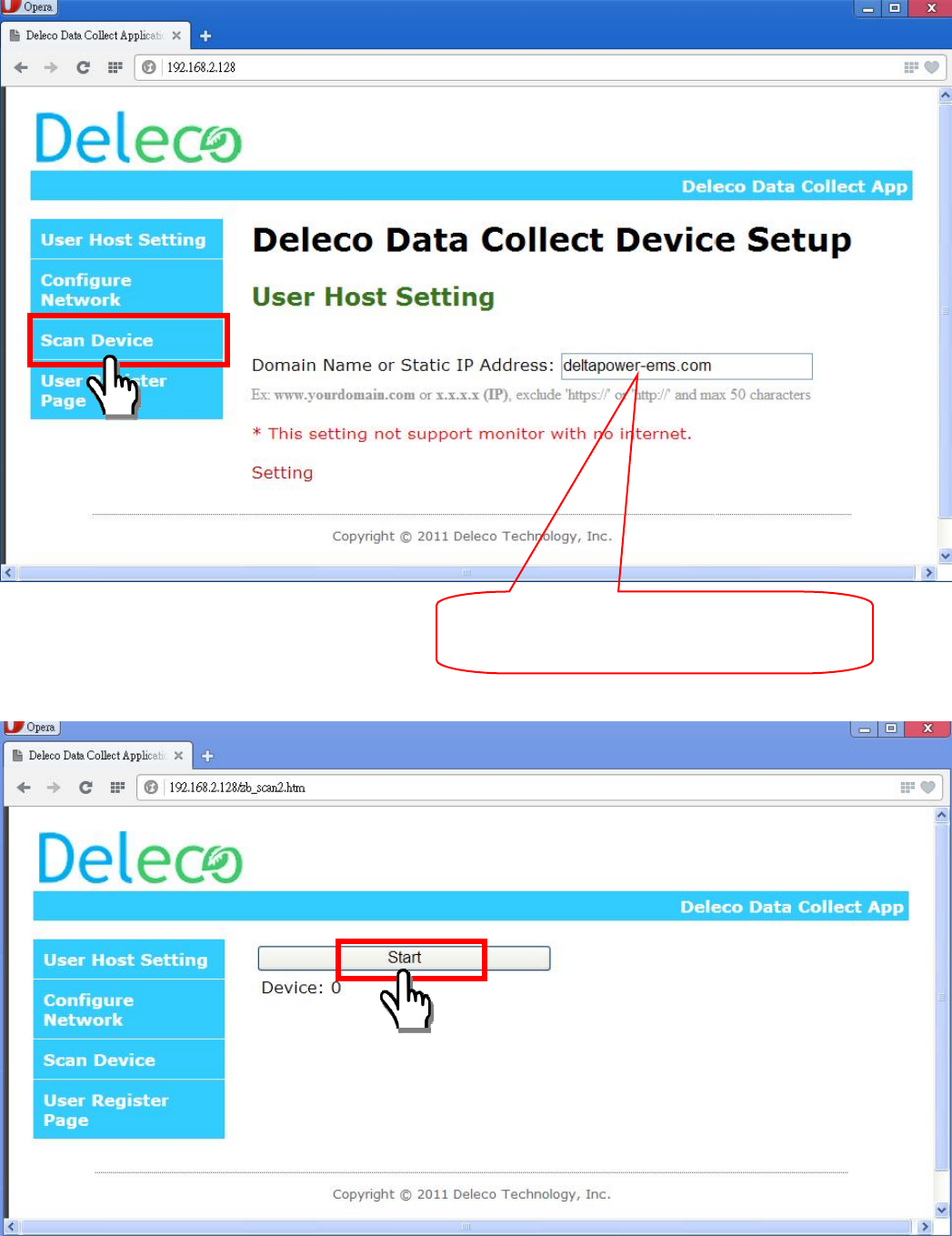
The screen should now show the setup page, click on “Scan Device”.
Then, press the “Start” button to search all micro inverters which you have installed.
This is system default and may be different
from what is shown on your screen.

Then, press the “Stop” button to stop searching when all micro inverters have found. Otherwise, it
will keep searching until 20 minutes time out.
After stopping, please disable the devices to kick out those micro inverters that do not belong to you.
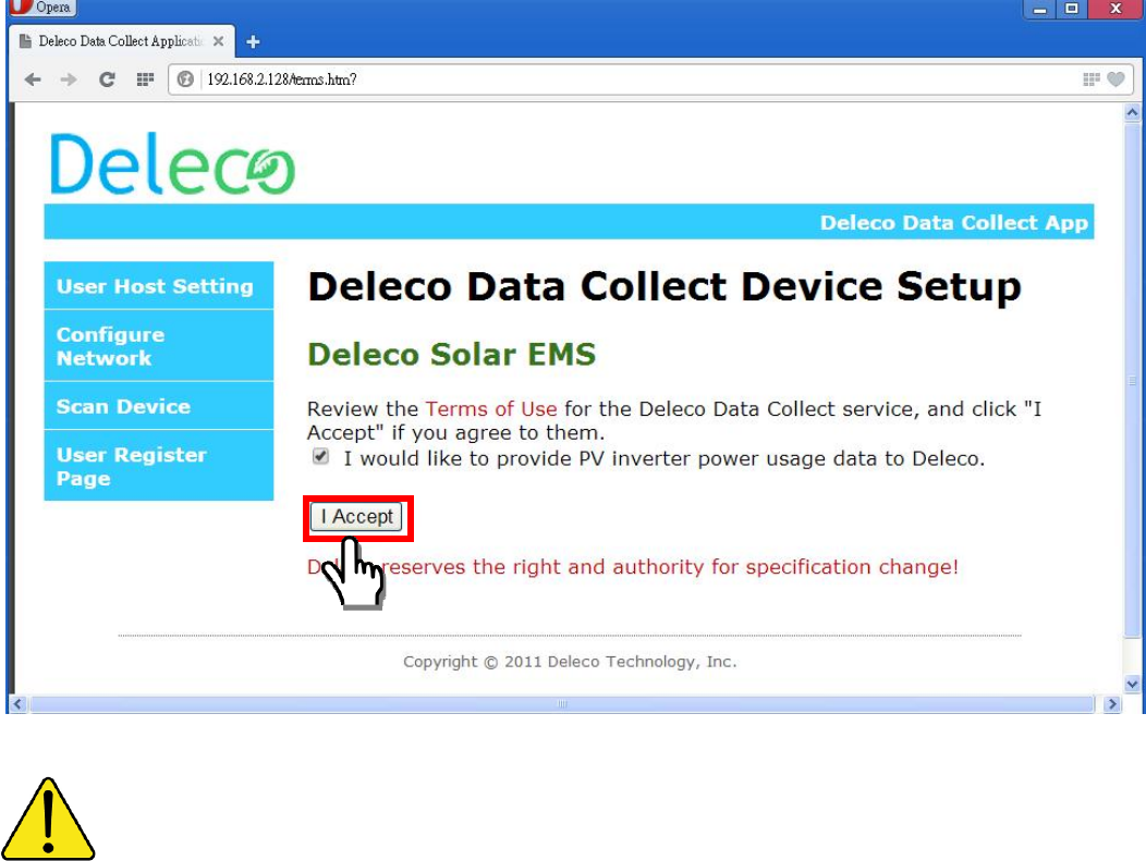
Then, press the “Confirm” button to finish scan device procedure.
After confirming, then, click “I Accept” button.
(Now, the Data Collector device should be set as an Ethernet device.)
Please skip to the Web Registration Procedure.
You can press the RESET button if you want to redo the setup.
Step 2:
Setup via Wireless (Using Wi-Fi Signal)
System configuration shown as below
Please make sure your PC has access to internet.
Please make sure AP/Router has enable the DHCP enabled.
On Data Collector OLED Display
Choose Wi-Fi DEVICE ( SELECT)
The OLED Display will alternatively show the IP address, date and time.
Once you finished the setup, the Time and Date will be updated automatically via the internet.
> Wi-Fi DEVICE
> ETHERNET DEVICE
169.254.0.1
TTL ENERGY: XX.XkWh
00/00/0000 00:00:00
TTL POWER: X.XW
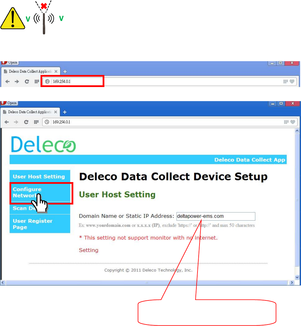
Antenna has directivity it should facing to Wi-Fi Router and PC.
Please connect your computer’s Wi-Fi to the SSID “DELTA_XXXXXXXXXXXX”
Open the web browser and key-in the IP address as shown on Data Collector OLED Display.
Click on “Configure Network”.
The screen will display two options; click “Scan Wireless Networks”.
This is system default and may be different
from what is shown on your screen.
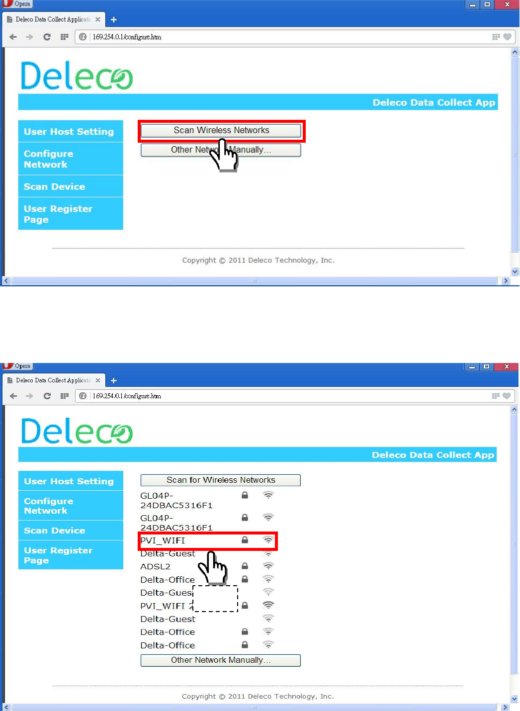
You should now see your Wi-Fi router will be listed.
Choose the SSID corresponding to your Wi-Fi Router. (Password maybe needed if your AP/Router
has encryption)
Step1
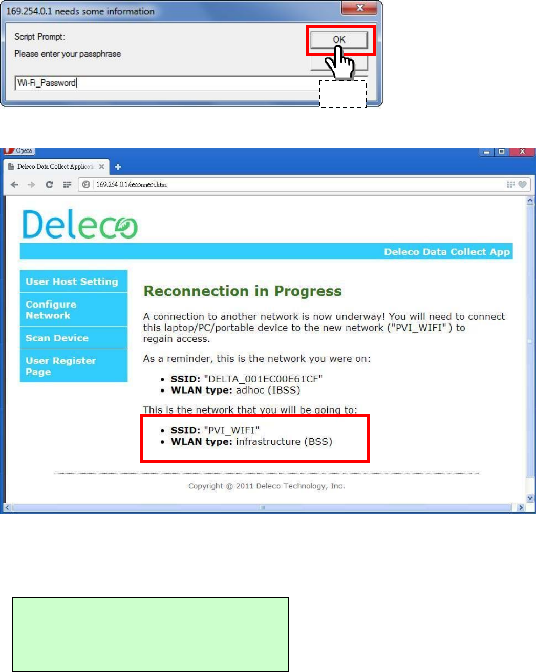
A confirmation message should be displayed as shown below.
After a certain timeframe, the IP address will appear on the Data Collector OLED Display.
(This IP address is assigned by your Wi-Fi Router, it maybe different from this SETUP GUIDE)
Please reconnect your computer’s Wi-Fi to your original internet connection.
192.168.X.X Web
TTL ENERGY: XX.XkWh
Step2
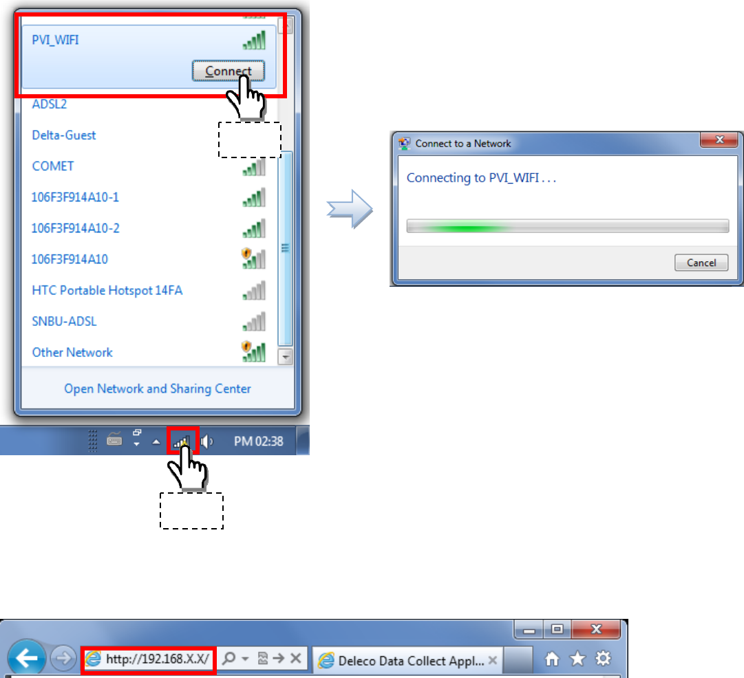
Open the web browser; key-in the IP address as shown on the Data Collector OLED Display.
The screen should now show the setup page, click on “Scan Device”.
Step1
Step2
Then, press the “Start” button to search all micro inverters which you have installed.
Then, press the “Stop” button to stop searching when all micro inverters have found. Otherwise, it
will keep searching until 20 minutes time out.
This is system default and may be different
from what is shown on your screen.
After stopping, please disable the devices to kick out those micro inverters that do not belong to you.
Then, press the “Confirm” button to finish scan device procedure.
After confirming, then, click “I Accept” button.
(Now, the Data Collector device is settled as a Wi-Fi device.)
Skip to the Web Registration Procedure.
You can press the RESET button if you want to redo the setup again.
Step 3:
Web Registration Procedure
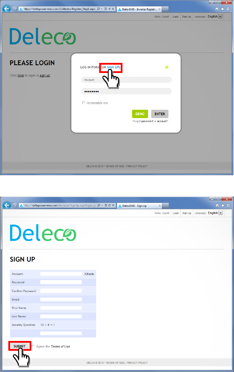
Once you click the “I Accept”, the web page will be redirect to our Deleco EMS sign up.
Sign up for new account.
Register your detailed personal data and click “SUBMIT”.
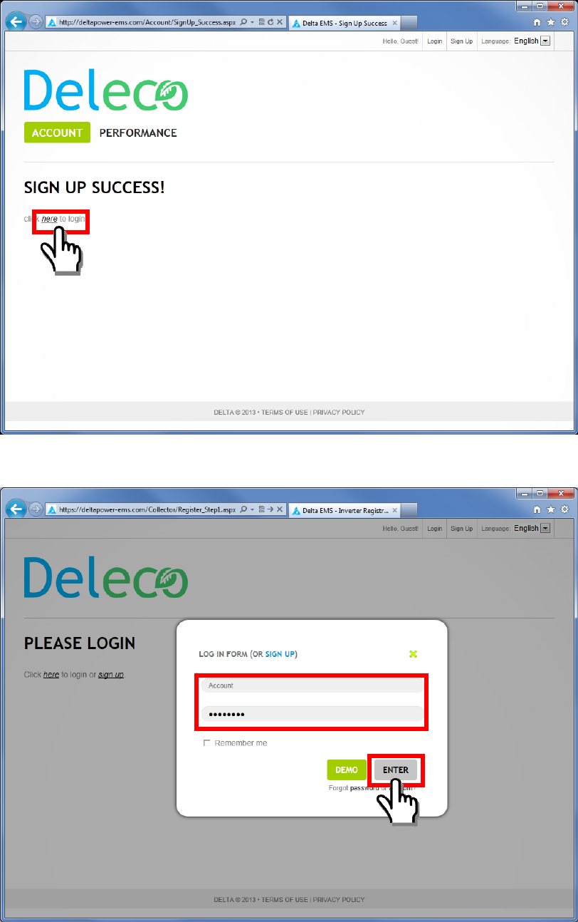
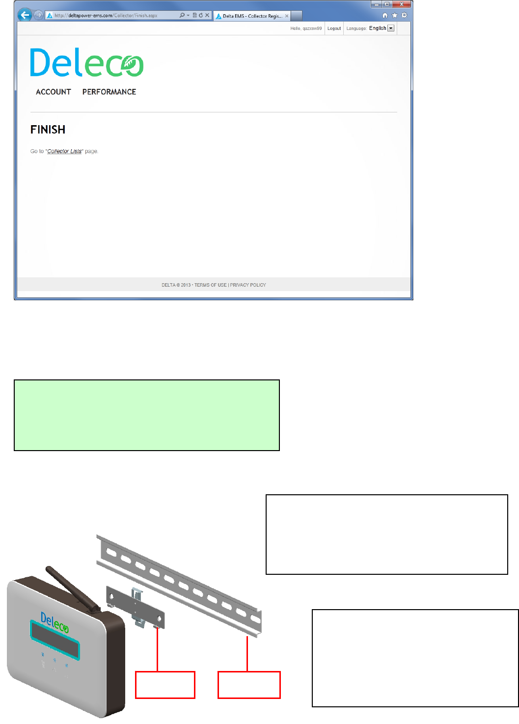
The page should then confirm your registration. Click “here” to login.
Login with the user account and password you registered.
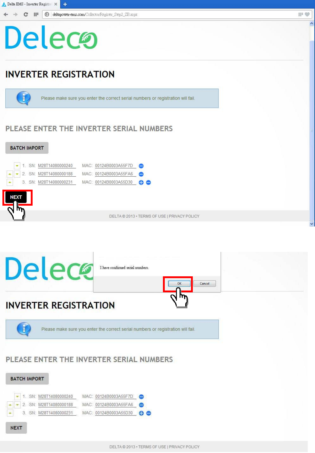
You can see the list of series number and MAC address from your micro inverters.
Then click the “NEXT”
The popup window show “I have confirmed the series number” and click “OK”.
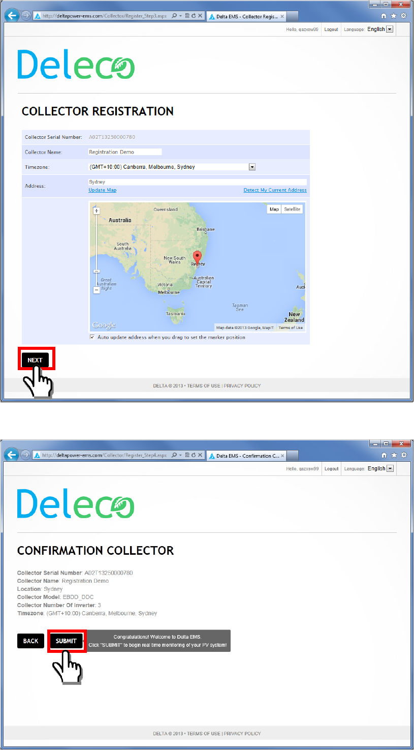
Register the Data Collector name, time zone and location.
Confirm the Data Collector information, then click “SUBMIT” button.
You will receive a confirmation of the completion of your registration.
The message “PLEASE AWAIT CONFIG” will be displayed on the Data Collector OLED
Display. The xx:xx time count is depending on how many micro inverters that you registered on
your Data Collector.
Step 4:
DIN Rail Mounting
PLEASE AWAIT CONFIG
XX:XX
Bracket DIN Rail
It is advisable to undertake all the configuration
operations before fixing the Data Collector and
installing it in the same location and position
used during the configuration.
Also choose a place close to a socket
(necessary for power, close to PV
System) and where the lower part of the
device, where all the connections are
present, remains accessible.
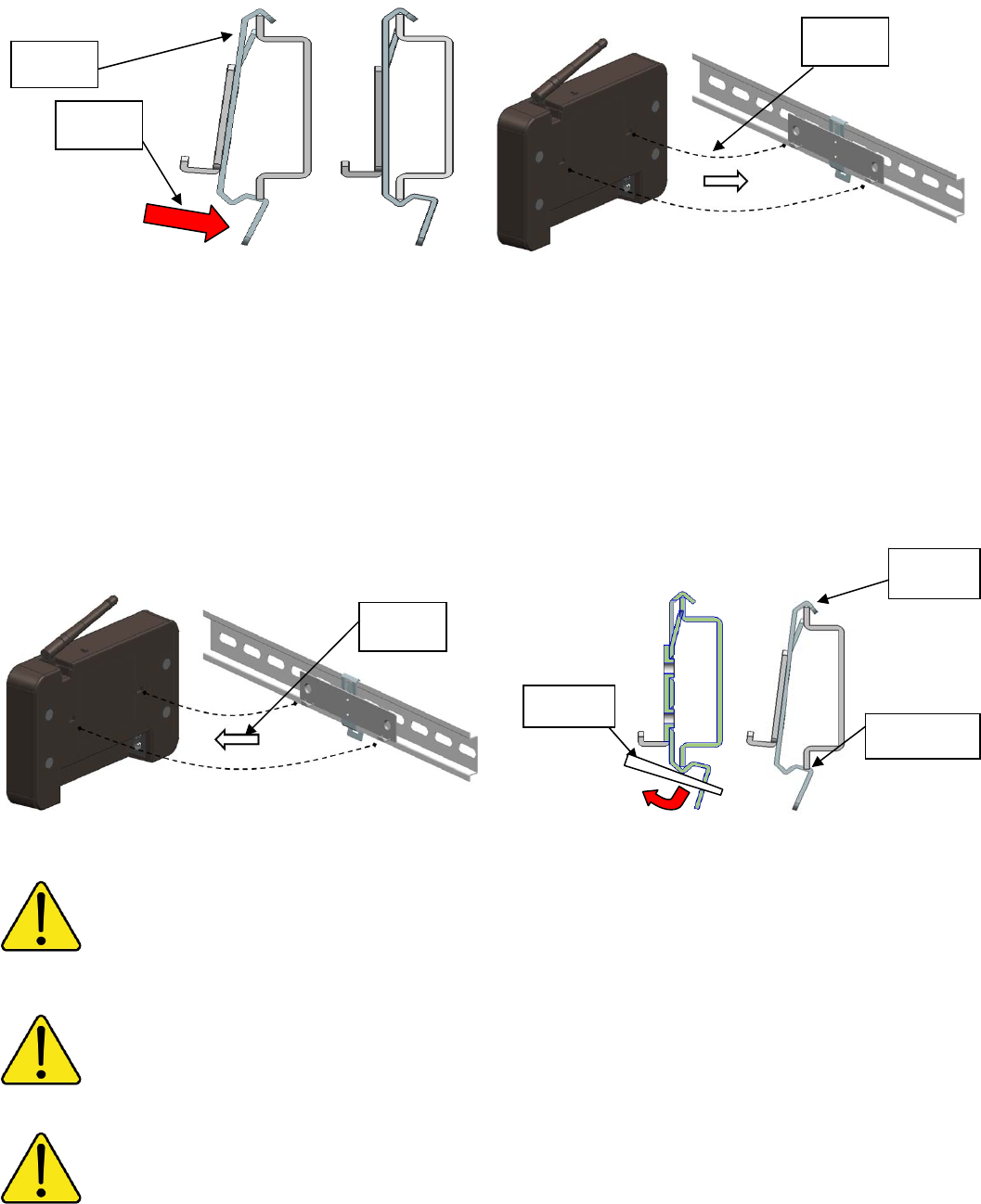
To install the Bracket on DIN Rail, please follow the steps below.
1. Clip the top side of the Bracket on the top side of the DIN Rail first.
2. Push the bottom of the Bracket to snap on the bottom side of the DIN Rail.
3. Hang the Data Collector on the Bracket on DIN Rail.
To release the Bracket from DIN Rail, please follow the steps below.
1. Take out the Data Collector from the Bracket on DIN Rail.
2. Insert a flathead screwdriver into the rectangular slot and turn it downward to release the clip
from the DIN Rail.
3. Remove the Bracket from the DIN Rail.
The installation must be done by qualified installers and/or licensed electrician according to the applicable
local regulations.
The connection of Micro Inverter System to the electricity distribution network must be approved by the
appropriate electrical distributor.
The installation must be carried out while the equipment is disconnected from the grid.
Step 3
Released
Step 1
Step
Step 3
Step 1
Step 2
Ste
p
2
Grid Code Setting
Once you finished the Micro Inverter registration process, then you MUST do the “Grid Code
Setting”.
It is the responsibility of the installer to follow local installation regulations and
guidelines in accordance with local electrical codes and Nation electrical codes for
electrical installation as specified by the Clean Energy Council.
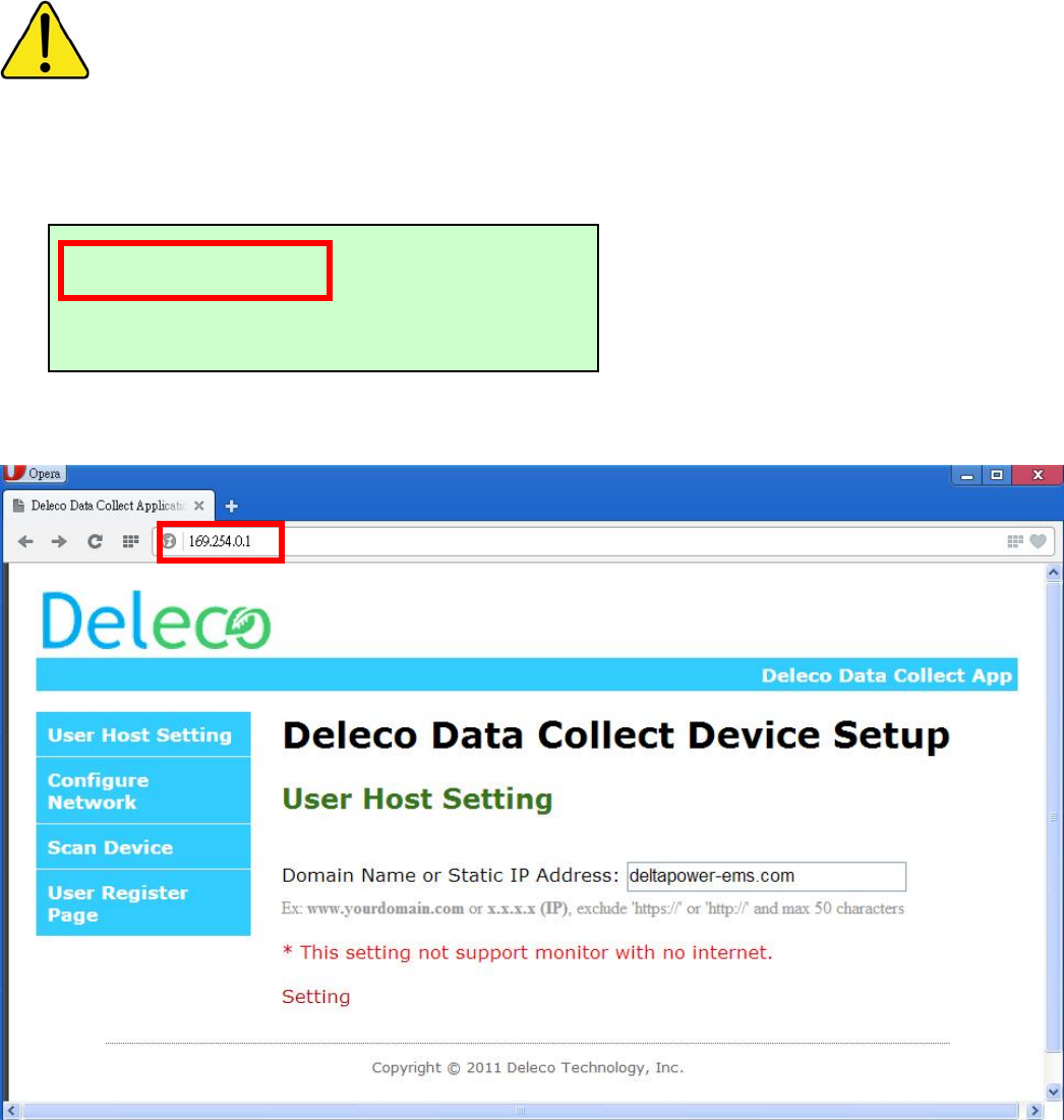
Step 1: Find the IP address shown on your Data Collector OLED display. (Note: The IP address
depends on your network environment.
Step 2: In your PC side, open your web browser, and key-in the IP address as shown on Data
Collector. Then, enter the Data Collector embedded web page.
Step 3: Add the #1234 after the IP address.
169.254.0.1
TTL ENERGY: 0.0kWh
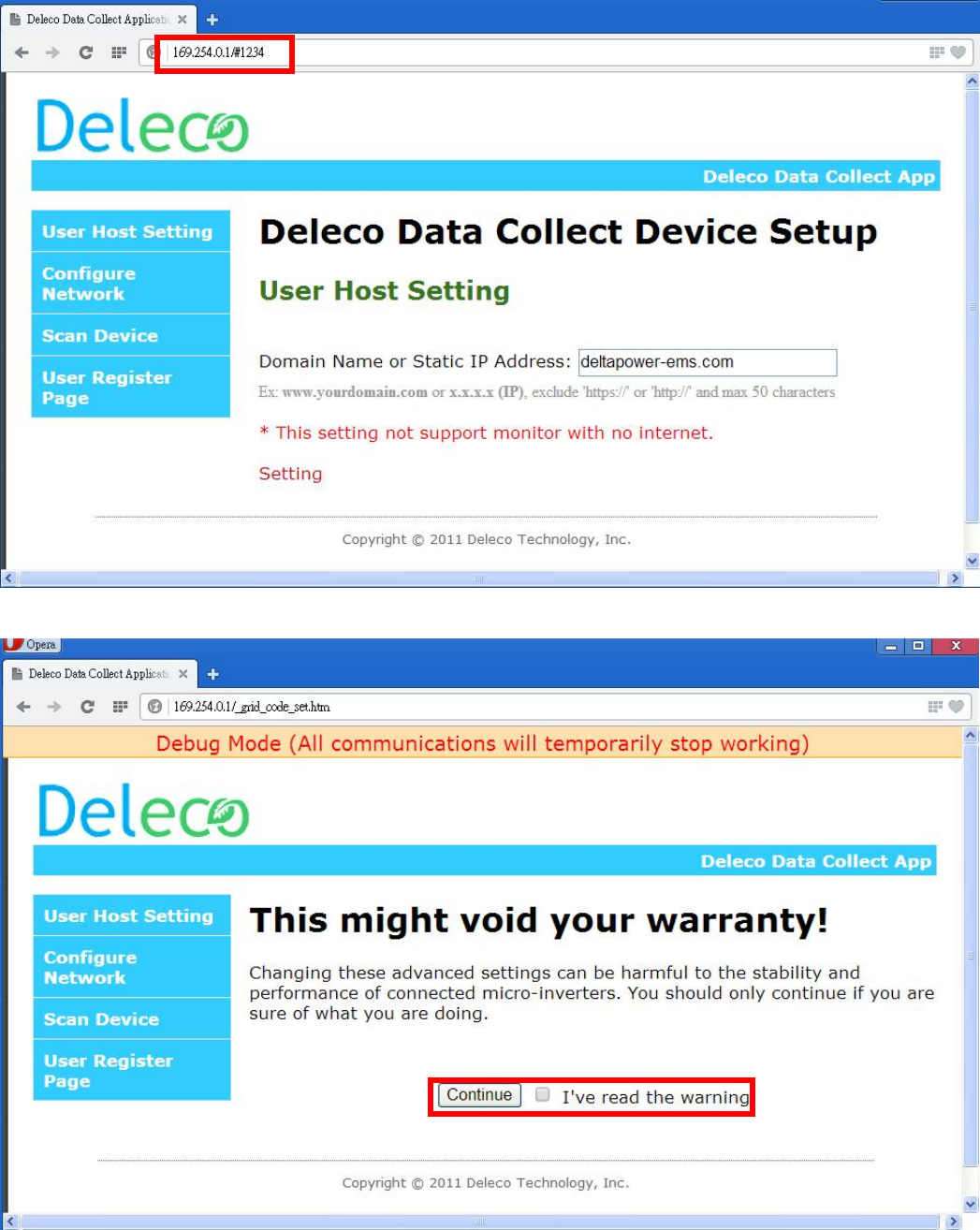
Step 4: Read the warranty and click “Continue”.
Step 5: Enter the setting grid code page.
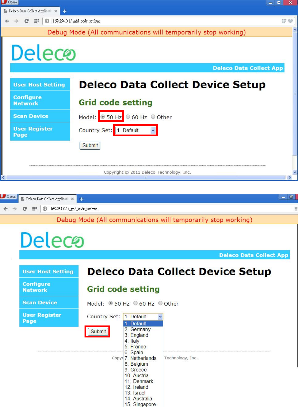
Step 6: Setting your grid code and Submit.
Structure of the OLED Display Menu
The buttons MENU , DOWN and SELECT are used to explore the menu on the
OLED Display.
By pressing MENU button during the normal operation, you can access the set up and
informative screens about the Data Collector.
During the normal operation of the
Data Collector & Micro Inverters, the
OLED Display is shown as left.
(Toggle displays every ~10 sec.)
192.168.X.X
TTL ENERGY xx.x kWh
13/01/2001 01:01:01
TTL POWER x.x W
OLED CONFIG
DATE/TIMING SET UP
DST CONFIG
LCD DISPLAY CONFIG
POWER DISPLAY TYPE
RSSI DETECT
WPS START
EXIT MENU
OLED CONFIG
DATE
/
TIMING SET UP
Press MENU button
DST CONFIG
LCD DISPLAY CONFIG
POWER DISPLAY TYPE
RSSI DETECT
WPS START
EXIT MENU
POWER ALWAYS ON
POWER SAVE MODE
DATE: dd/mm/yy
TIME: 00:00:00
ENABLE
DISABLE
POWER DISPLAY
STATUS DISPLAY
TOTAL
INDIVID. (30 sec)