Delta Electronics orporated DFZM-TS220 ZigBee module User Manual DFZM TS220
Delta Electronics Incorporated ZigBee module DFZM TS220
UserManual.wiki
>
Delta Electronics orporated
>
DFZM-TS220 User Manual
>
manual model 1
Contents
1.
manual model 1
2.
manual model 2
manual model 1
Navigation menu
Upload a User Manual
Namespaces
Wiki Guide
HTML
PDF
Info
Views
User Manual
Discussion / Help
Navigation
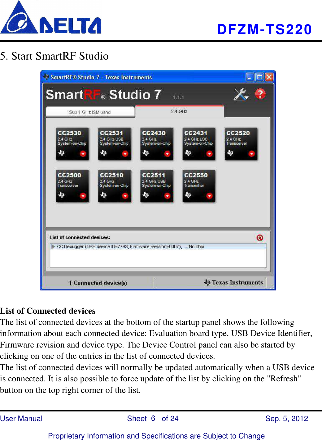
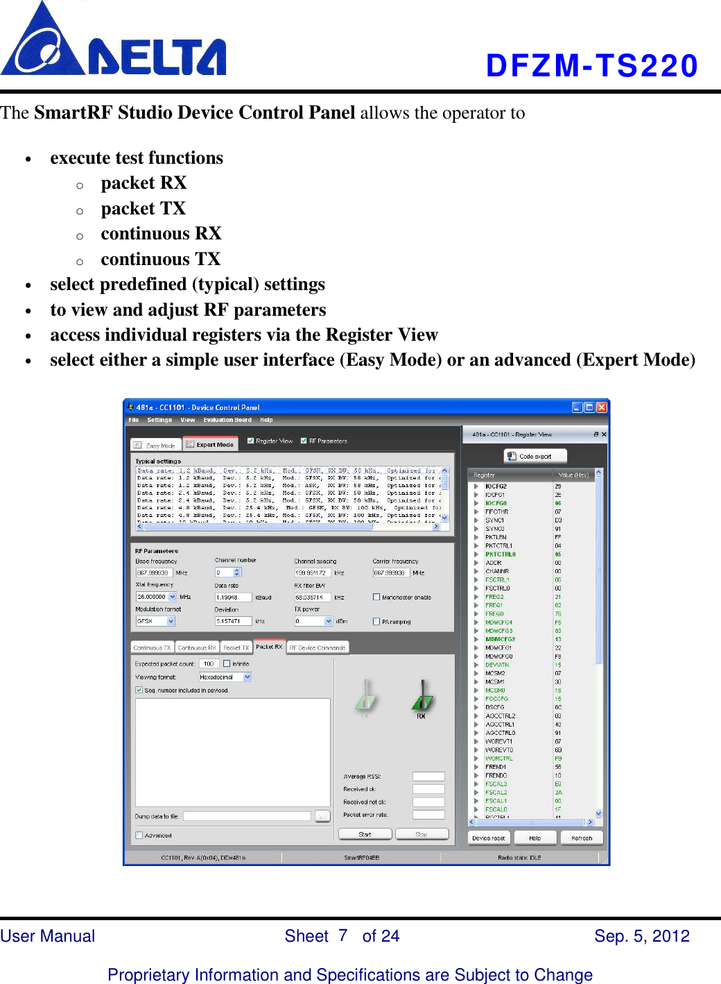
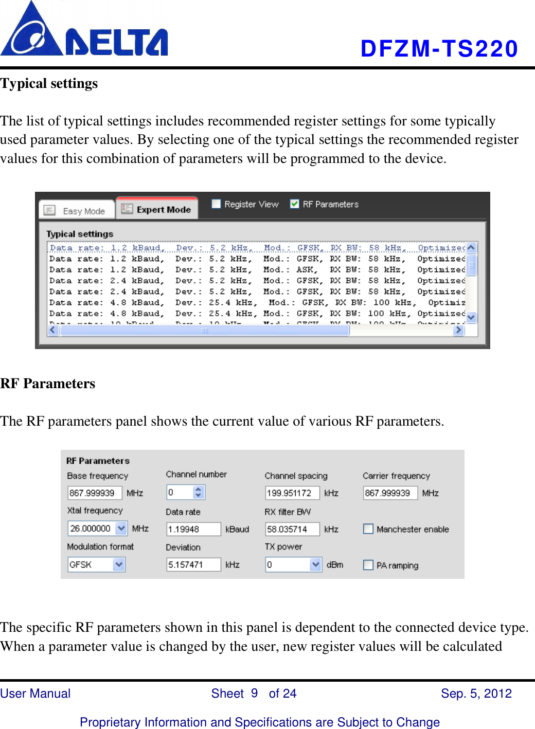
![DFZM-TS220 User Manual Sheet of 24 Sep. 5, 2012 Proprietary Information and Specifications are Subject to Change 5 4. Installing USB driver To get the required USB driver for the CC Debugger, it is necessary to install one of the tools listed below: • • • • SmartRF Studio www.ti.com/tool/smartrftm-studio • • • • SmartRF Flash Programmer www.ti.com/tool/flash-programmer • • • • PurePath Wireless Configurator http://www.ti.com/tool/purepath-wl-cfg Alternatively, you can download “Cebal – CCxxxx Development Tools USB Driver for Windows x86 and x64” [3] which is a standalone installer including only the device driver. After having installed the driver, connect the CC Debugger to the PC. The USB driver will be installed automatically. You can quickly check that the debugger has been associated correctly with the USB device driver by opening the Windows Device Manager. The debugger should appear as a “Cabal controlled device”. Verify driver installation](https://usermanual.wiki/Delta-Electronics-orporated/DFZM-TS220.manual-model-1/User-Guide-1796892-Page-5.png)