Delta Electronics orporated DFZM-TS220 ZigBee module User Manual DFZM TS220
Delta Electronics Incorporated ZigBee module DFZM TS220
Contents
- 1. manual model 1
- 2. manual model 2
manual model 1

DFZM-TS220
User Manual Sheet of 24 Sep. 5, 2012
Proprietary Information and Specifications are Subject to Change
1
User Manual
DELTA
DFZM-TS220
2.4GHz IEEE 802.15.4 Module
DFZM-TS220
User Manual Sheet of 24 Sep. 5, 2012
Proprietary Information and Specifications are Subject to Change
2
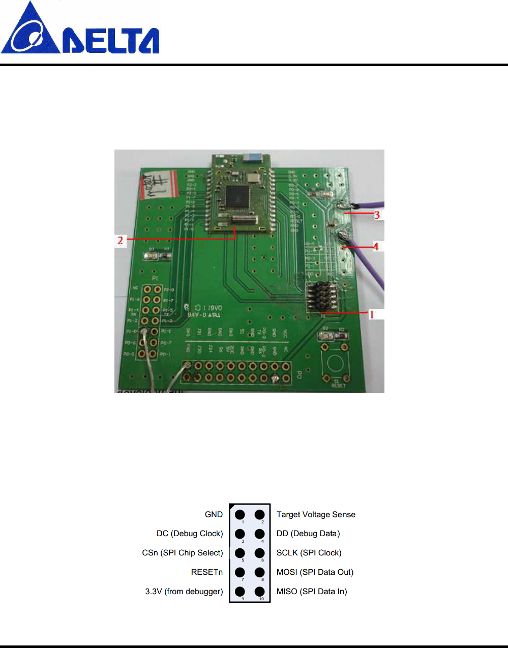
1. DFZM-TS220/TS221 EVB
This section describes the various interfaces and jumper
settings for the DFZM-TS22x evaluation board.
Description:
1 - 10 PIN F/W write connector (J3)
2 - DFZM-TS221 ZigBee module
3 – Power positive (Vcc)
4 - Power negative (Gnd)
J3 connector pin out
DFZM-TS220
User Manual Sheet of 24 Sep. 5, 2012
Proprietary Information and Specifications are Subject to Change
3
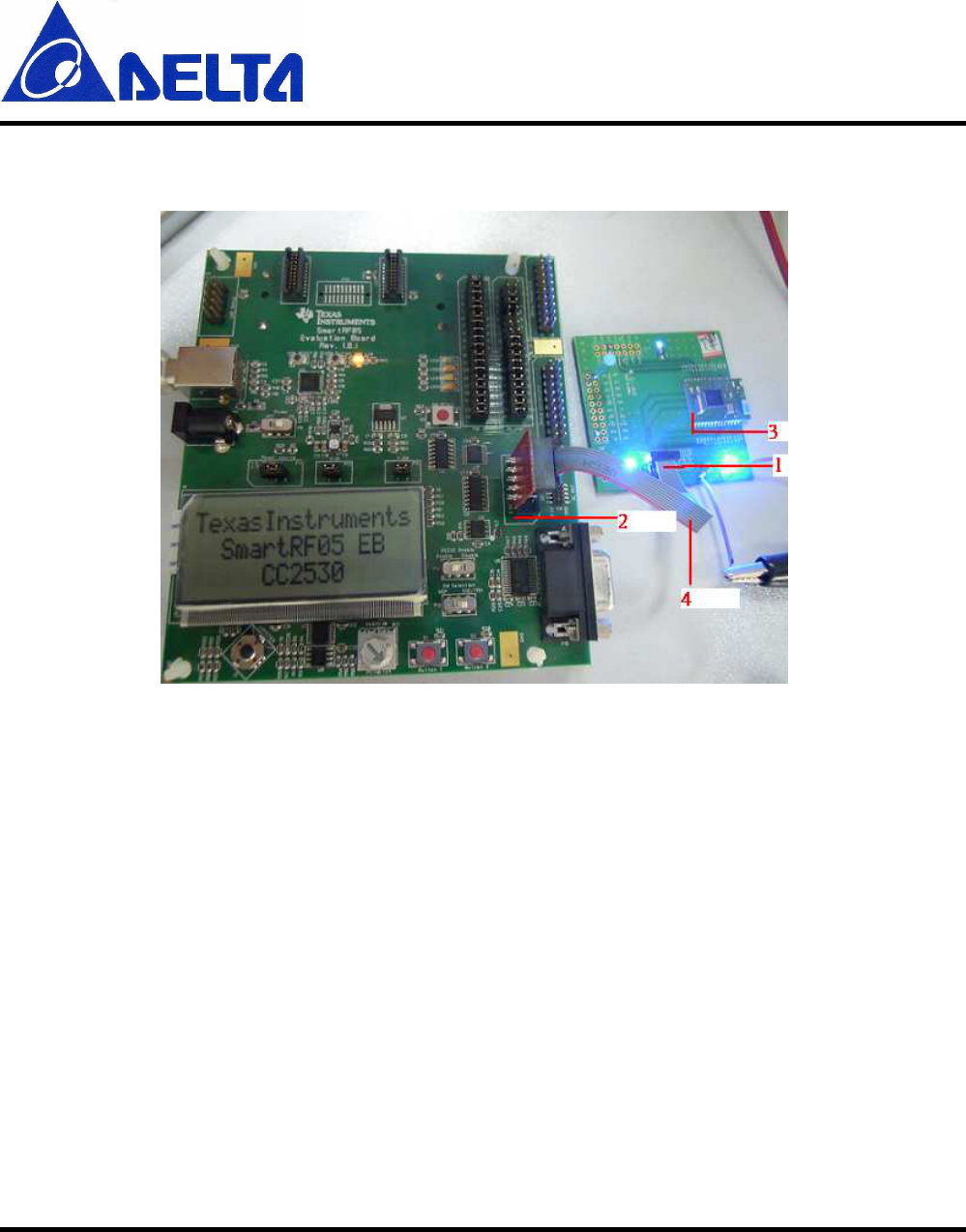
2. Updating the Firmware by the SmartRF EVB
1. Daughter Board 10 PIN Connector (J3)
2. SmartRF EVB 10 PIN Connector (P3 ExtSoC Debug)
3. TS221 module
4. TI 10 PIN cable
(i.e. Daughter EVB need 3/3.3V)
DFZM-TS220
User Manual Sheet of 24 Sep. 5, 2012
Proprietary Information and Specifications are Subject to Change
4
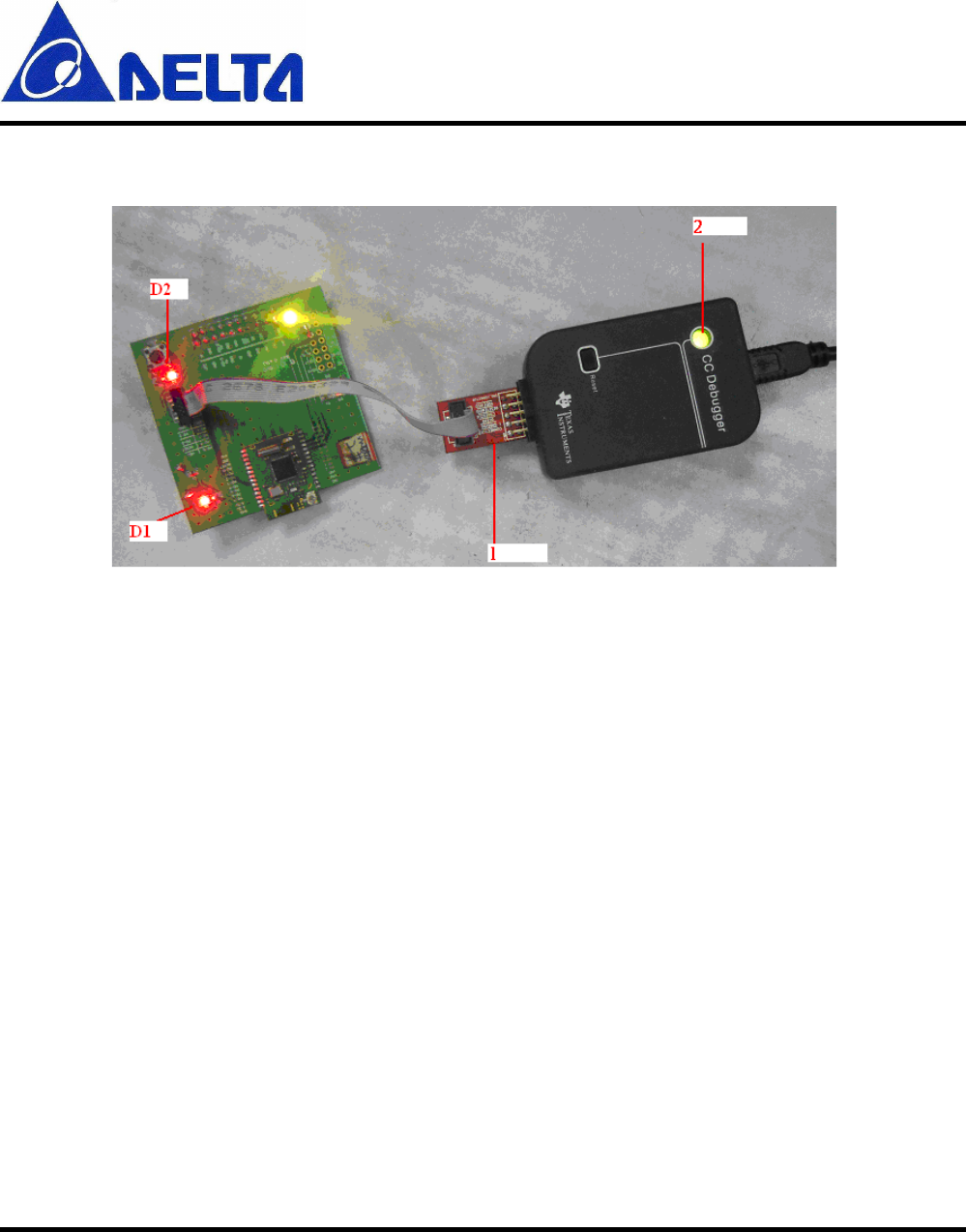
3. Updating the Firmware by the CC Debugger
1. CC Debugger 10PIN Connector
2. CC Debugger LED (If a module is detected, the LED will be
GREEN. If no modules are detected, the LED will be RED)
(i.e. Daughter Board don’t need 3/3.3V)
Daughter EVB LEDs:
D1: Power LED
D2: Status LED (The LED is blinking while the firmware is being
updated!)
DFZM-TS220
User Manual Sheet of 24 Sep. 5, 2012
Proprietary Information and Specifications are Subject to Change
5
4. Installing USB driver
To get the required USB driver for the CC Debugger, it is necessary to install one of
the tools listed below:
•
• •
• SmartRF Studio www.ti.com/tool/smartrftm-studio
•
• •
• SmartRF Flash Programmer www.ti.com/tool/flash-programmer
•
• •
• PurePath Wireless Configurator http://www.ti.com/tool/purepath-wl-cfg
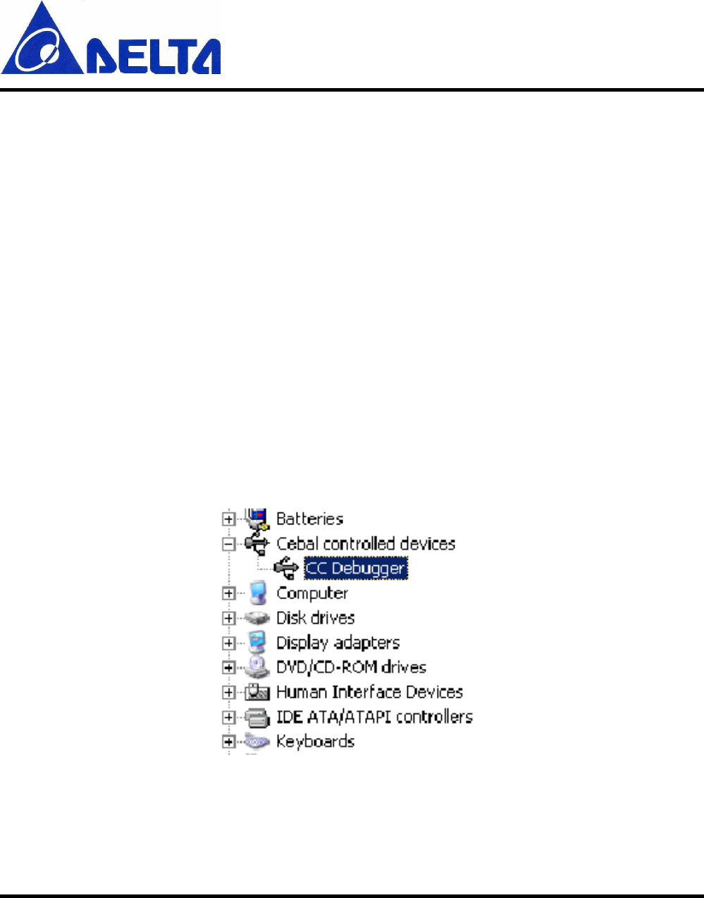
Alternatively, you can download “Cebal – CCxxxx Development Tools USB Driver
for Windows x86 and x64” [3] which is a standalone installer including only the
device driver. After having installed the driver, connect the CC Debugger to the PC.
The USB driver will be installed automatically. You can quickly check that the
debugger has been associated correctly with the USB device driver by opening the
Windows Device Manager. The debugger should appear as a “Cabal controlled
device”.
Verify driver installation
DFZM-TS220
User Manual Sheet of 24 Sep. 5, 2012
Proprietary Information and Specifications are Subject to Change
6
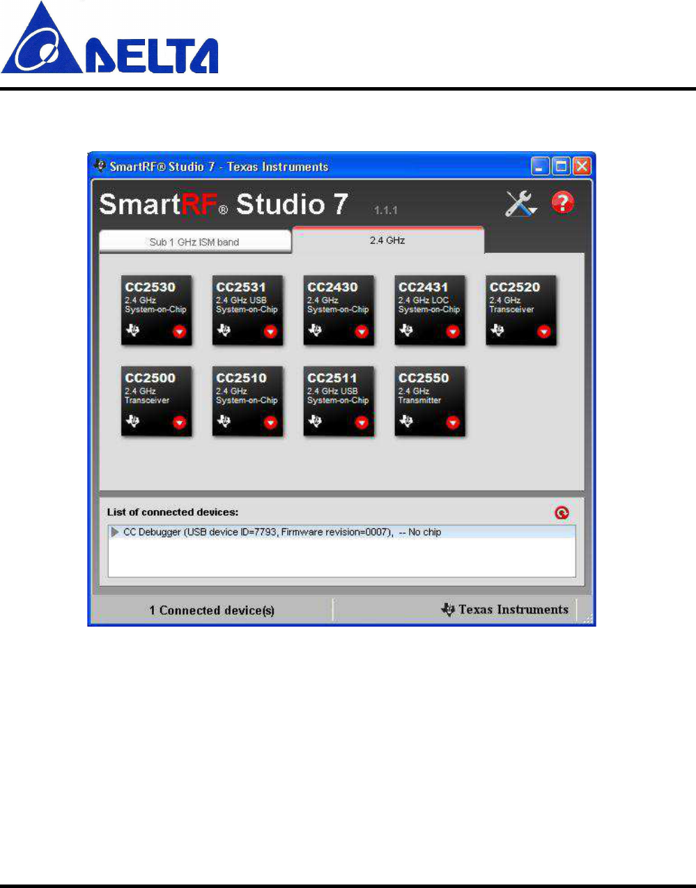
5. Start SmartRF Studio
List of Connected devices
The list of connected devices at the bottom of the startup panel shows the following
information about each connected device: Evaluation board type, USB Device Identifier,
Firmware revision and device type. The Device Control panel can also be started by
clicking on one of the entries in the list of connected devices.
The list of connected devices will normally be updated automatically when a USB device
is connected. It is also possible to force update of the list by clicking on the "Refresh"
button on the top right corner of the list.
DFZM-TS220
User Manual Sheet of 24 Sep. 5, 2012
Proprietary Information and Specifications are Subject to Change
7
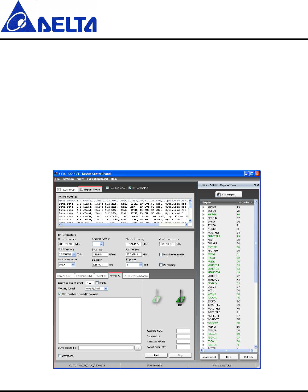
The
SmartRF Studio Device Control Panel
allows the operator to
•
execute test functions
o
packet RX
o
packet TX
o
continuous RX
o
continuous TX
•
select predefined (typical) settings
•
to view and adjust RF parameters
•
access individual registers via the Register View
•
select either a simple user interface (Easy Mode) or an advanced (Expert Mode)

DFZM-TS220
User Manual Sheet of 24 Sep. 5, 2012
Proprietary Information and Specifications are Subject to Change
8
Easy Mode
Easy Mode provides a simple user interface for packet transmission and reception. The
user can select between two test modes; Packet TX and Packet RX in the bottom panel.
Quick Start
A packet TX/RX test between two devices can be started simply by selecting 'Packet TX'
on one of the devices and 'Packet RX' on the other. Press start on the 'Packet RX' device
first, then press start on the 'Packet TX' device to start the packet transmission.
Select Configuration
Select a configuration with the predefined protocol and packet format, data rate and
frequency. Each configuration programs the connected device with a list of register
values according to the configuration parameters. Make sure that the same configuration
is used on both the transmitting and receiving device. Details of the selected packet
format can be seen in either the 'Packet TX' or 'Packet RX' panels at the bottom of the
screen.
Expert Mode
Expert Mode provides a more advanced user interface than Easy Mode. From the Expert
Mode the user can change advanced RF parameters for the connected device. The expert
mode includes a typical settings panel, an RF parameter panel and the following test
function panels: Continuous TX, Continuous RX, Packet TX, Packet RX and RF Device
Commands.
The various panels visible from Expert Mode are described in the following sections.
DFZM-TS220
User Manual Sheet of 24 Sep. 5, 2012
Proprietary Information and Specifications are Subject to Change
9
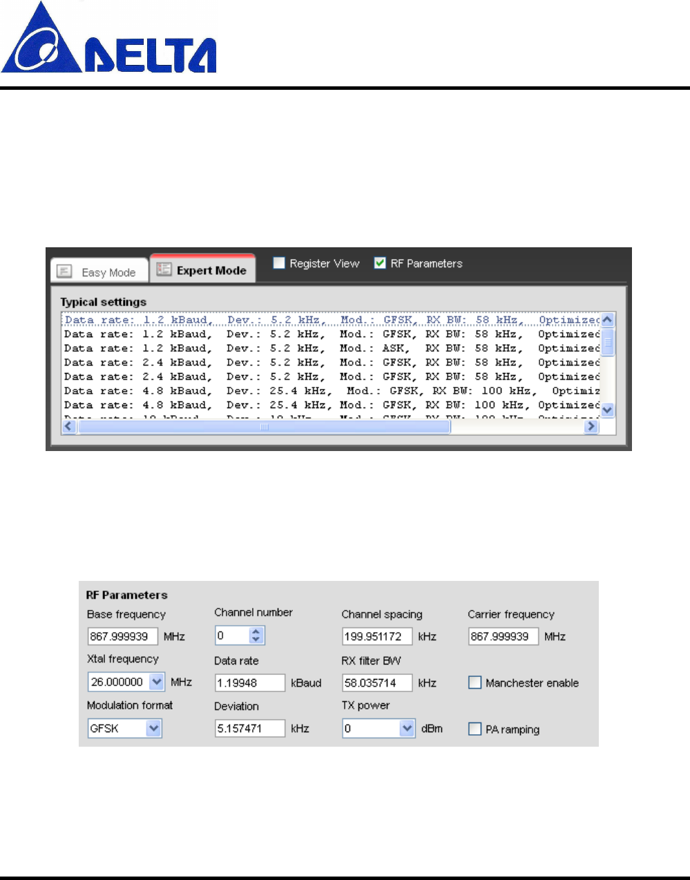
Typical settings
The list of typical settings includes recommended register settings for some typically
used parameter values. By selecting one of the typical settings the recommended register
values for this combination of parameters will be programmed to the device.
RF Parameters
The RF parameters panel shows the current value of various RF parameters.
The specific RF parameters shown in this panel is dependent to the connected device type.
When a parameter value is changed by the user, new register values will be calculated
DFZM-TS220
User Manual Sheet of 24 Sep. 5, 2012
Proprietary Information and Specifications are Subject to Change
10
and the register view is updated accordingly. If not operating in offline mode, the register
values will also be written to the connected device. Likewise if a register value is
changed, either from register view or indirectly by selecting a new typical or easy mode
setting, the affected RF parameters in this panel will be updated accordingly.
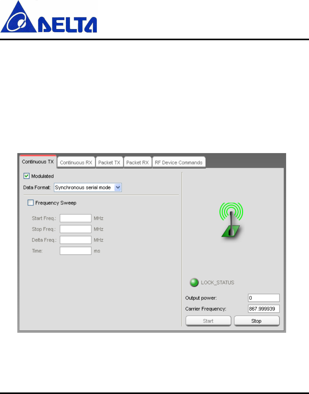
Continuous TX
The Continuous TX panel is used to set the device in a mode where it transmits a
continuous signal.
Modulated
This check box enables/disables modulation of the transmitted signal

DFZM-TS220
User Manual Sheet of 24 Sep. 5, 2012
Proprietary Information and Specifications are Subject to Change
11
Data Format
If the modulation is enabled, the source of modulation data is selected from this drop
down list.
Frequency Sweep
Enable/disable sweep transmission over multiple frequencies. 'Start Freq.' and 'Stop Freq.'
sets the start and end frequency of the sweep. 'Delta Freq.' sets the size of each frequency
hop between start and stop frequency. 'Time' sets the time to transmit on each frequency.
Input/Output signal
Depending on the connected device, the Continous TX mode can be configured to use an
external signal as source for the RF output signal.
SmartRF04EB and TrxEB: CC1100, CC1101, CC1150, CC2500 and CC2550
TrxEB: CC1120, CC1121, CC1175
The General Digital Output(GDO) pins are configured as input for data signal and output
of the clock signal.
SmartRF04EB
DTEST0(GDO0):
Data from function generator into RF
Device.
Serial Synchronous mode:
DTEST1(GDO2):
Clock from RF Device to external
scope.
Asynchronous transparant
mode: DTEST0(GDO0):
Data from function generator into RF
Device.

DFZM-TS220
User Manual Sheet of 24 Sep. 5, 2012
Proprietary Information and Specifications are Subject to Change
12
TrxEB
P7 pin 8(GDO0):
Data from function generator into RF
Device.
Serial Synchronous mode:
P7 pin 4(GDO2):
Clock from RF Device to external
scope.
Asynchronous transparant
mode: P7 pin 8(GDO0):
Data from function generator into RF
Device.
CC430
The GDO pins for the radio of CC430 is mapped to port 2.
CC430Fx137EM
Port
2.6(GDO0):
Data from function generator into RF
Device.
Serial Synchronous mode: Port
2.7(GDO2):
Clock from RF Device to external
scope.
Asynchronous transparant
mode:
Port
2.6(GDO0):
Data from function generator into RF
Device.
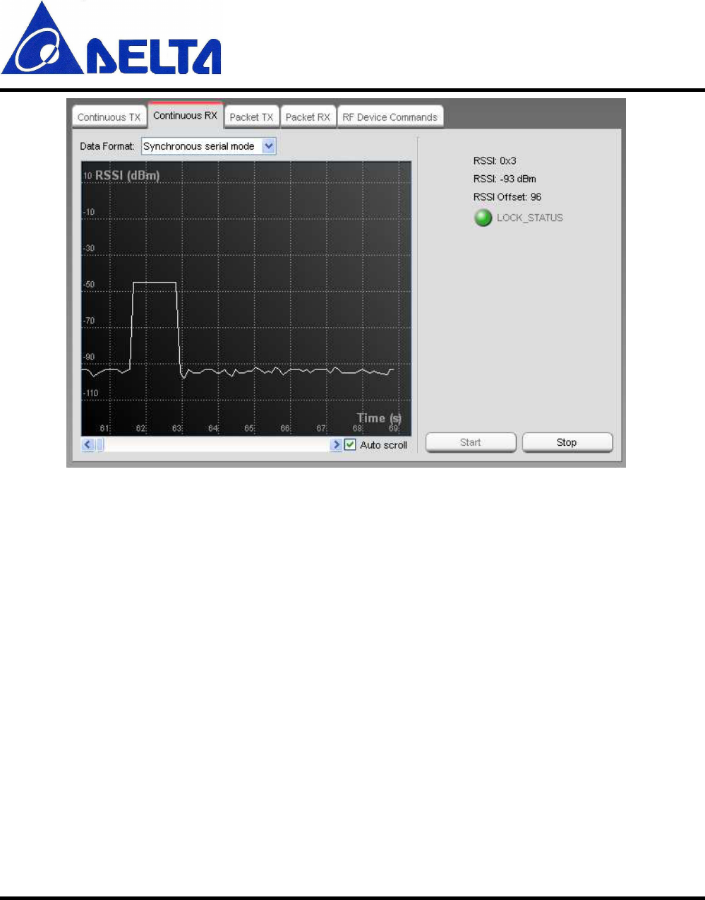
Continuous RX
From this panel the connected device is set in continuous receive mode and plot the RSSI
value (Received Signal Strength Indicator).
DFZM-TS220
User Manual Sheet of 24 Sep. 5, 2012
Proprietary Information and Specifications are Subject to Change
13
The measured RSSI in dbm is plotted on the graph as a function of time. On the right side
of the panel the numerical value of the RSSI is given in both a raw format and in the
calculated dBm units. The RSSI offset used for the calculation is also shown. The actual
RSSI offset is dependent on the connected device type and is found in the datasheet.
The RSSI value will be stored in an internal buffer of a fixed size and when the
maximum number of elements is reached, the next value will be stored from the
beginning again. It is a circular buffer of 5000 elements. That means it will only contain
measurements from the last 9 - 10 minutes. The exact number depends on the sample rate.
Theoretically this is every 100 ms, but due to the load of other tasks on the PC, this will
vary and be a bit higher.
Output signal
Depending on the connected device, the Continous RX mode will be configured to direct
the incoming RF signal to a connector on the given Evaluation Board.

DFZM-TS220
User Manual Sheet of 24 Sep. 5, 2012
Proprietary Information and Specifications are Subject to Change
14
SmartRF04EB and TrxEB: CC1100, CC1101, CC1150, CC2500 and CC2550
TrxEB: CC1120, CC1121, CC1175
The General Digital Output(GDO) pins are configured as output for data signal and
output of the clock signal.
SmartRF04EB
DTEST0(GDO0):
Data from RF Device to external
scope.
Serial Synchronous mode:
DTEST1(GDO2):
Clock from RF Device to external
scope.
Asynchronous transparant
mode: DTEST0(GDO0):
Data from RF Device to external
scope.
TrxEB
P7 pin 8(GDO0):
Data from RF Device to external
scope.
Serial Synchronous mode:
P7 pin 4(GDO2):
Clock from RF Device to external
scope.
Asynchronous transparant
mode: P7 pin 8(GDO0):
Data from RF Device to external
scope.
CC430
The GDO pins for the radio of CC430 is mapped to port 2.
DFZM-TS220
User Manual Sheet of 24 Sep. 5, 2012
Proprietary Information and Specifications are Subject to Change
15
CC430Fx137EM
Port
2.6(GDO0):
Data from RF Device to external
scope.
Serial Synchronous mode: Port
2.7(GDO2):
Clock from RF Device to external
scope.
Asynchronous transparant
mode:
Port
2.6(GDO0):
Data from RF Device to external
scope.
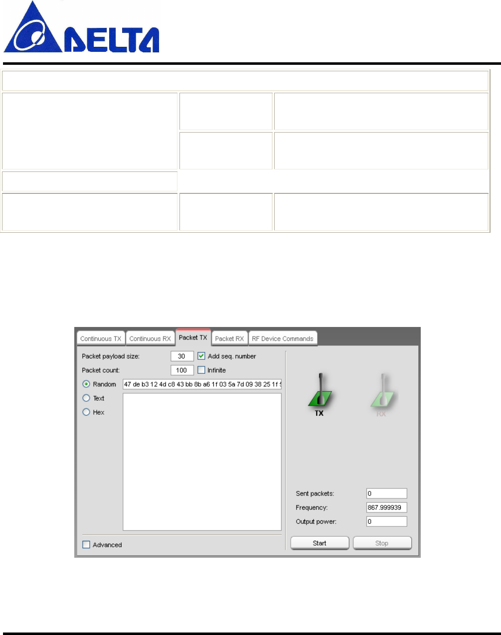
Packet TX
This panel controls packet transmission.
DFZM-TS220
User Manual Sheet of 24 Sep. 5, 2012
Proprietary Information and Specifications are Subject to Change
16
Packet payload size
This field select the size of the payload. The maximum size is dependent on the
connected device type. A warning is given if the maximum size is exceeded. Optionally a
2 bytes sequence number can be added at the end of the payload.
Packet count
This field selects the number of packets to be sent, optionally infinite.
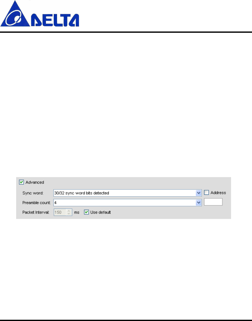
Advanced options
The Advanced options is available for the convenience of the advanced users. The
options will vary from device to device
.
Example from CC1101:
Sync word
The combined sync-word qualifier mode. See register definition for details (E.g.:
CC11xx register MDMCFG2).
Preamble count
The minimum number of preamble byte to be transmitted.
Address
If the Address option is checked, the address value will be inserted into the packet
DFZM-TS220
User Manual Sheet of 24 Sep. 5, 2012
Proprietary Information and Specifications are Subject to Change
17
payload, after the length byte.
Packet interval
The packet interval option can be used to change the delay time between each packet.
When the "Use default" is checked, the value calculated by SmartRF Studio is shown.
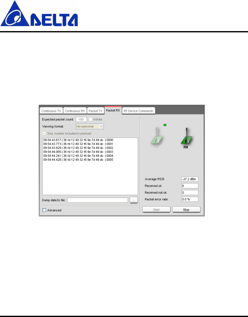
Packet RX
This panel control packet receive. Statistics for the Packet RX test is shown at the right
side of the panel.
Expected packet count
This field selects the number of packets expected to be received, optionally infinite. The
value is used to calculate the packet error rate.
DFZM-TS220
User Manual Sheet of 24 Sep. 5, 2012
Proprietary Information and Specifications are Subject to Change
18
Sequence number
Set the 'Seq. number included in payload.' check box if the transmitter is configured to
include sequence number in the payload.
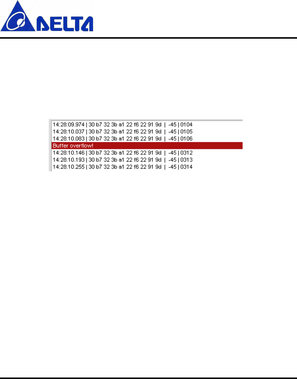
EB Buffer overflow
The "EB Buffer overflow!" indication is given when the internal packet buffer on the
Evaluation Board MCU is full. This can happen when the PC application is not able to
read packets from the buffer fast enough. The EB MCU tries to store the incoming packet,
but does not succeed since the buffer is full. In this case an "overflow" message is sent to
the PC.
The problem can be solved by increasing the time between each packet sent from the
transmitter. If the transmitter is controlled by SmartRF Studio in Packet TX, it is possible
to change the packet interval.
DFZM-TS220
User Manual Sheet of 24 Sep. 5, 2012
Proprietary Information and Specifications are Subject to Change
19
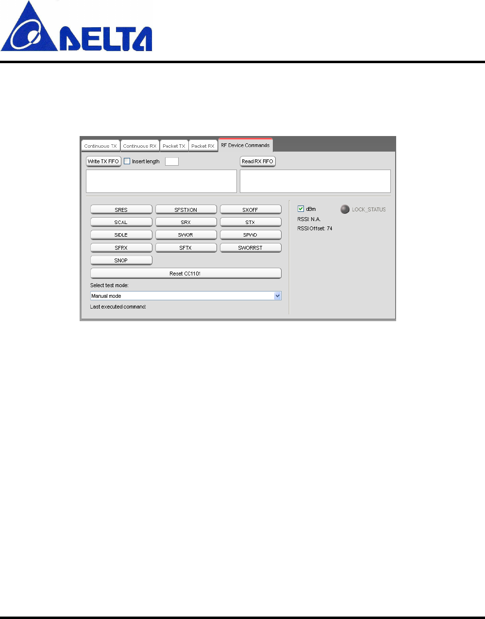
RF Device Commands
This panel is used to issue individual command strobes to the chip.
The specific command strobes shown in this panel are dependent on the connected device
type, and may not include all strobes supported by the device. Consult the datasheet for a
description of supported command strobes.
Select test mode
The user should first select the specific test mode from the drop down list to be used from
the device command panel. This will configure the device' register values according to
the test mode e.g. 'Packet TX' will set recommended register values for packet
transmission. If 'Manual mode' is selected no register values are changed. This may result
in some register values differing from recommended values for a specific test mode.
Write TX FIFO
This button is used to write data into the device' TX FIFO. The data is specified by the
user in the edit box below. If the 'Insert length' check box is checked a length byte will be
DFZM-TS220
User Manual Sheet of 24 Sep. 5, 2012
Proprietary Information and Specifications are Subject to Change
20
included as the first byte.
Read RX FIFO
Read device' RX FIFO.
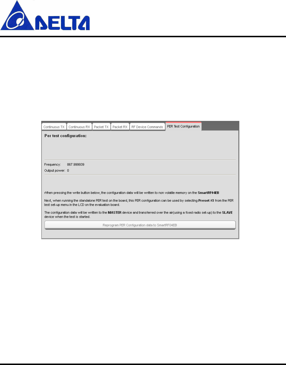
PER test configuration
This panel is used to write Packet Error Rate test configuration to the DFZM-TS220
EVB.
The standalone PER test with the SmartRF04EB board is only available for CC1100,
CC1101, CC1100E and CC2500.
The selected SmartRF Studio settings will be written to the non volatile memory on the
SmartRF04EB board, so when the SmartRF04EB is disconnected from SmartRF Studio,
it is possible to run the PER test with the programmed settings.

DFZM-TS220
User Manual Sheet of 24 Sep. 5, 2012
Proprietary Information and Specifications are Subject to Change
21
The configuration data can be used by selecting the frequency band and Preset #3 from
the test set-up menu in the LCD on the evaluation board. The applicable Frequency band
will be shown below the "write" button and on the LCD on the evaluation board when the
configuration data has been reprogrammed.
The configuration data will be written to the MASTER device and transferred over the
air(using a fixed radio set-up) to the SLAVE device when the test is started. This means
the SLAVE device should be started before the MASTER device.
If the MASTER device have problems to send the configuration data over the air to the
SLAVE device, it might be that the devices are to close to each other. Make sure that the
devices are at least 2 meters from each other.
See the kit user guides for more details about the standalone PER test.
DFZM-TS220
User Manual Sheet of 24 Sep. 5, 2012
Proprietary Information and Specifications are Subject to Change
22
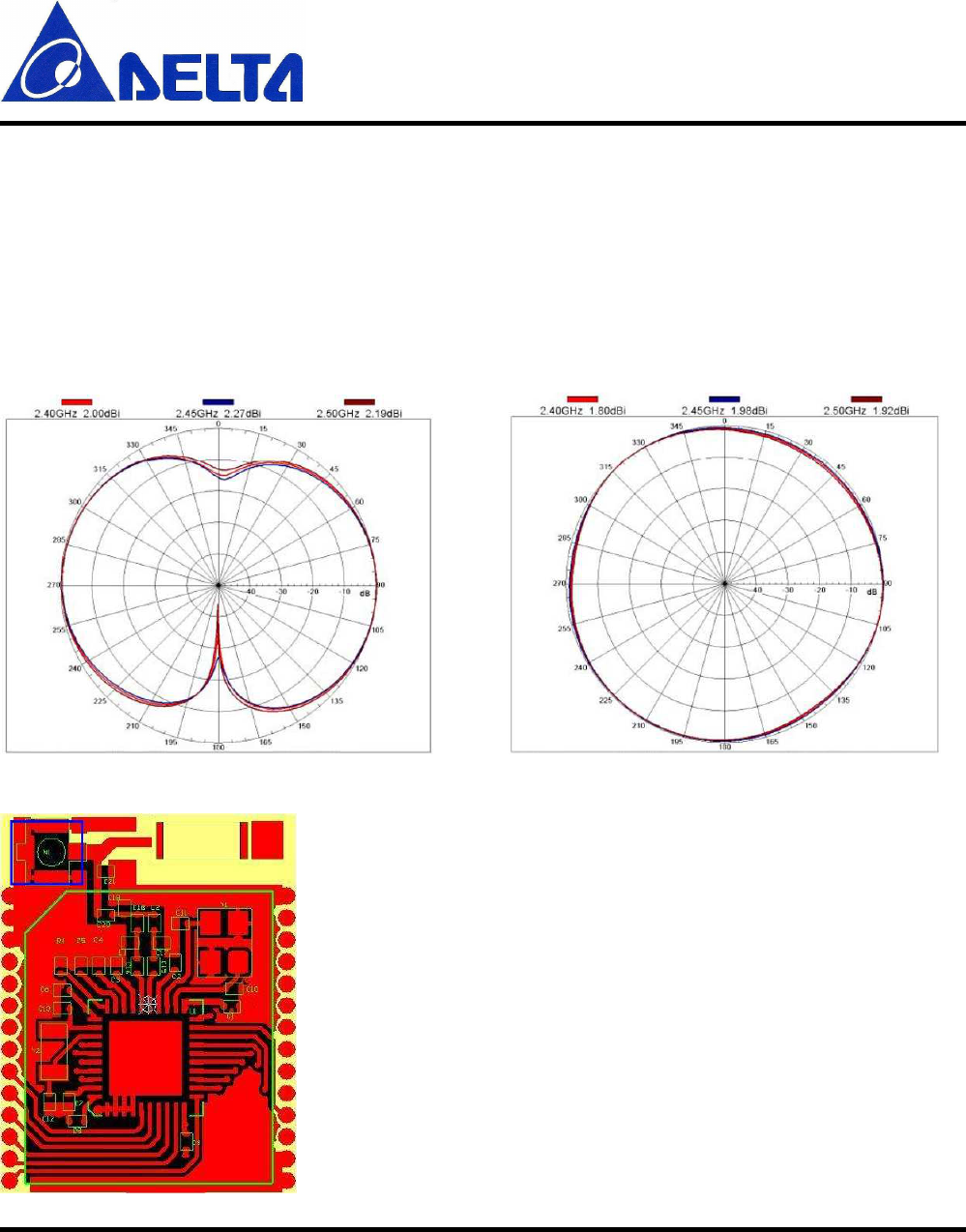
6. Antenna Information
Production Number AR007WSW01A03
Frequency Range 2400MHZ ~ 2500MHz
Peak Gain 2dBi
Radiated Patten
H-Plane V-Plane
Location

DFZM-TS220
User Manual Sheet of 24 Sep. 5, 2012
Proprietary Information and Specifications are Subject to Change
23
Federal Communications Commission (FCC) Statement
You are cautioned that changes or modifications not expressly approved by the part responsible for
compliance could void the user’s authority to operate the equipment.
Section 15.105 (a) for Class A Device
For a Class A digital device or peripheral, the instructions furnished the user shall include the following
or similar statement, placed in a prominent location in the text of the manual:
NOTE: This equipment has been tested and found to comply with the limits for a Class A digital device,
pursuant to Part 15 of the FCC Rules. These limits are designed to provide reasonable protection against
harmful interference when the equipment is operated in a commercial environment. This equipment
generates, uses, and can radiate radio frequency energy and, if not installed and used in accordance with
the instruction manual, may cause harmful interference to radio communications. Operation of this
equipment in a residential area is likely to cause harmful interference in which case the user will be
required to correct the interference at his own expense.
15.105(b) for Class B Device (usual)
Federal Communications Commission (FCC) Statement
This equipment has been tested and found to comply with the limits for a Class B digital device,
pursuant to part 15 of the FCC rules. These limits are designed to provide reasonable protection against
harmful interference in a residential installation. This equipment generates, uses and can radiate radio
frequency energy and, if not installed and used in accordance with the instructions, may cause harmful
interference to radio communications. However, there is no guarantee that interference will not occur in
a particular installation. If this equipment does cause harmful interference to radio or television
reception, which can be determined by turning the equipment off and on, the user is encouraged to try to
correct the interference by one or more of the following measures:
-Reorient or relocate the receiving antenna.
-Increase the separation between the equipment and receiver.
-Connect the equipment into an outlet on a circuit different from that to which the receiver is connected.

DFZM-TS220
User Manual Sheet of 24 Sep. 5, 2012
Proprietary Information and Specifications are Subject to Change
24
-Consult the dealer or an experienced radio/TV technician for help.
15.19(a)(1) licensed project (GSM Device)
This device complies with part 15 of the FCC Rules. Operation is subject to the condition that this
device does not cause harmful interference.
Part 15.19(a)(3) unlicensed project (WLAN Device)
This device complies with Part 15 of the FCC Rules. Operation is subject to the following two
conditions:
1) this device may not cause harmful interference, and
2) this device must accept any interference received, including interference that may cause undesired
operation of the device.
End Product Labeling:
The final end product must be labeled in a visible area with the following: “Contains FCC ID:
H79DFZM-TS220”.
Manual Information That Must be Included:
The OEM integrator has to be aware not to provide information to the end user regarding how to install
or remove. This RF module in the user’s manual of the end product which integrates this module. The
user’s manual for OEM Integrators must include the following information in a prominent location