Delta Electronics ARUBA41 802.11 a+b+g Wireless AP User Manual 0500128 A41 IG indd
Delta Networks, Inc. 802.11 a+b+g Wireless AP 0500128 A41 IG indd
Users Manual
PACKAGE CONTENTS
• 1 x Aruba 41 Wireless Access Point
• 1 x Quick Installation Guide (this document)
Inform your supplier if there are any incorrect, missing or
damaged parts. If possible, retain the carton, including the
original packing materials. Use them to repack the product
in case there is a need to return it.
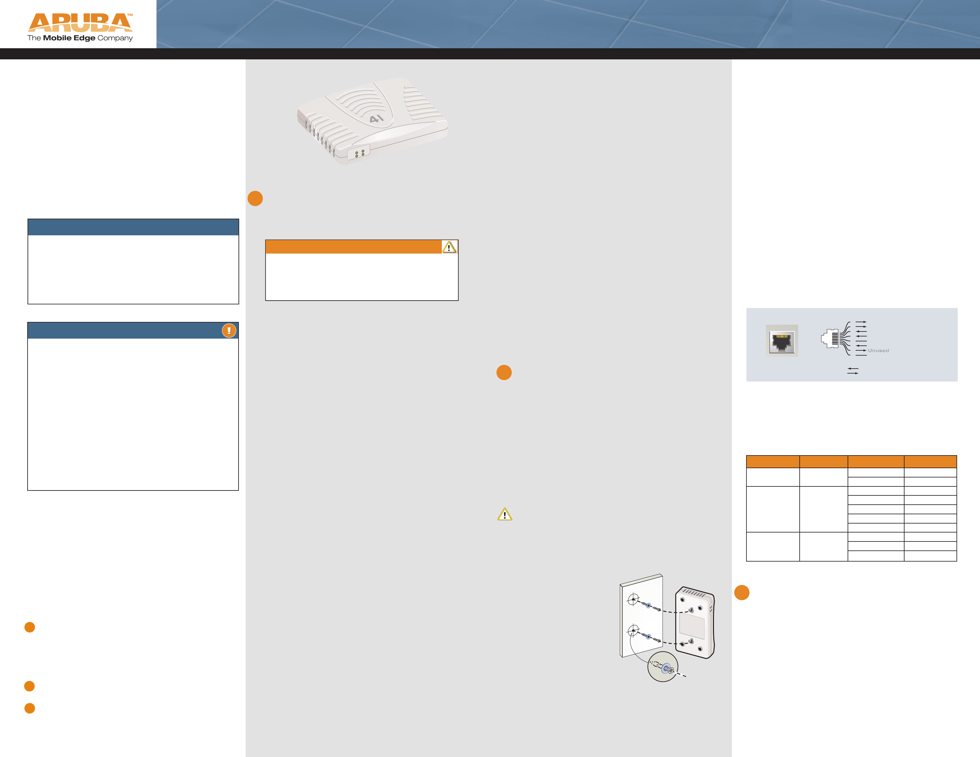
1 Install two screws in the wall or
shelf. If attaching the device to
drywall, we recommend using
appropriate wall anchors (not
included).
2 Align the Aruba 41 mount-
ing slots to capture the surface
screws.
3 Orient the antenna. For best per-
formance, swivel the antenna so
that it is oriented vertically.
Figure 0-1: Aruba 41 Mounting
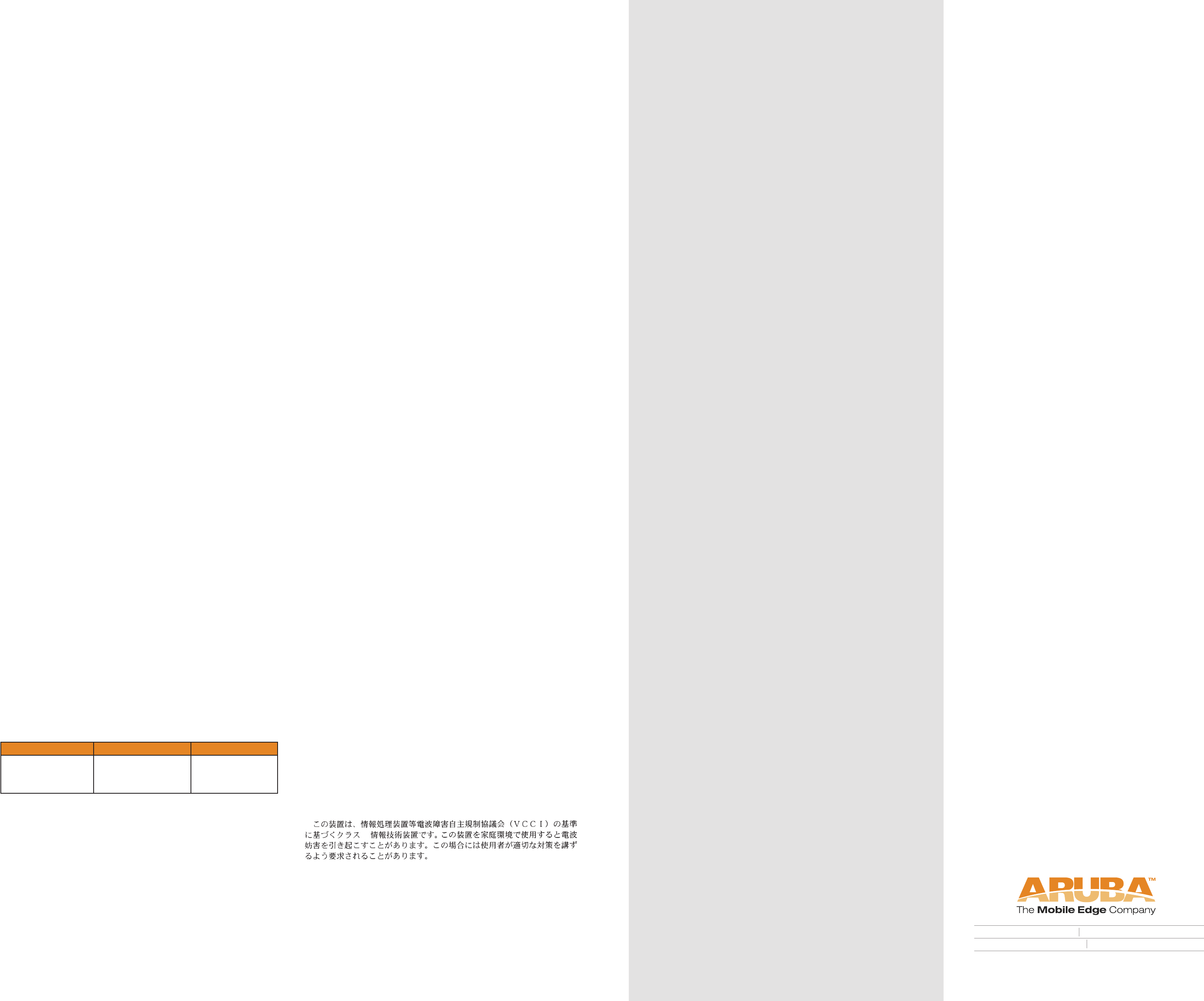
Aruba 41
10/100 Mbps Ethernet
RJ-45 Female
Pin-Out
*POE
Unused
Unused
Unused
Unused
1
2
3
4
5
6
7
8
ETH Rx+ (POE negative*)
ETH Rx– (POE negative*)
ETH Tx+
(POE positive*)
ETH Tx–
(POE positive*)
Direction
Input
Output
Figure 0-2: Aruba 41 FE Port
Aruba 41 Wireless Access Point
Quick Installation Guide
2
1
BEFORE GETTING STARTED
Before installing your Aruba 41 wirless access point,
please ensure you have the following:
• 1 x Fast Ethernet cable of required length
• 1 x 802.3af compliant Power over Ethernet source
(PSE) - Aruba Mobility Controller or Midspan device
• 1 x Aruba Mobility Controller provisioned on the
network:
- with Layer 2/3 network connectivity your Aruba 41
- One of the following network services:
- Aruba Discovery Protocol (ADP)
- DNS server with an “A” record
(see section 1; Provisioning the Aruba 41)
- DHCP Server with vendor specifi c options
(see section 1; Provisioning the Aruba 41)
Optional:
• Mounting screws (not supplied)
Provisioning using DHCP with
Vendor Specific Options
A standards compliant DHCP server can be confi gured to
return the host Aruba Mobility Controller’s IP address through
Vendor Specifi c Options (option 43) in the DHCP reply. If the
host Mobility Controller’s IP address is obtained via DHCP, it
will be used for uploading the Aruba access point’s software
image and confi guration.
NOTE: If you have location-specifi c confi gurations for your Access Points, you will
need to apply this confi guration information using AP Reprovisioning.
AP Reprovisioning
Once an AP is associated to an Aruba Mobility Controller, it is
capable of being Reprovisioned if necessary. AP Reprovisioning
is the process by which APs are assigned unique confi guration
characteristics, for example, location codes. Location codes are
important for recalibration and triangulation. For details on AP
Reprovisioning, see the ArubaOS User Guide.
AP Provisioning
Recommended only in instances where APs require to be
pre-staged or provisioned in advance of shipment and fi nal
network installation (suchas as Remote Access Point (RAP)
deployments), in AP programming mode, AP confi guration
parameters are defi ned on the Aruba Mobility Controller via
command line interface or web interface, where they can
then be uploaded to individual access points as required.
Installing the Aruba 41
Select a location as close as possible to the center of the
intended coverage area. The service location should be free from
obstructions or obvious sources of interference. Normally, the
higher you place an access point or air monitor, the better its
performance.
The Aruba 41 can be mounted on a wall using the mounting
slots on the bottom of the unit.
NOTE: For dimensions, see “Product Specifi cations”. Allow 5 cm (2”) additional space
on the right-hand side for cables and ensure enough space for antenna articulation.
Using the Built-In Mounting Slots
The keyhole-shaped slots on the back of the Aruba 41 can be
used to attach the device upright to an indoor wall or shelf.
CAUTION: Do not use the mounting slots to hang the Aruba 41 from the ceiling,
sideways, or in any place where it could fall on people or equipment. For more secure
installation, use one of the optional mounting kits.
To hang the Aruba 41 upright using the mounting slots,
perform the following steps:
Connecting Required Cables
NOTE: Aruba 41 Access Points are intended only for installation in Environment A as
defi ned in IEEE 802.3.af, Power over Ethernet. All interconnected equipment must be
contained within the same building, including the interconnected equipment’s associ-
ated LAN connections.
The 10/100 Mbps Ethernet (FE) port is used to connect the AP
to a 10Base-T/100Base-TX (twisted-pair) Ethernet LAN segment.
Use a 4- or 8-conductor, Category 5 UTP, straight-through FE
cable.X and automatically adjusts for straight-through or cross-
over cables. The maximum length for FE cables is 100 meters
(325 feet). Install cables in accordance with all applicable local
and national regulations and practices.
Connecting Cables & Power
1 Connect one end of the FE cable directly to the Aruba
41 FE port
2 Connect the other end of the FE cable to one of the
following:
- To a network port on the Mobility Controller, or
- To a network mid-span device that supports 802.3af
compliant port
FE Port Specifi cations
The 10/100 Mbps Ethernet (FE) port is located on the right-hand
side of the Aruba 41 and has an RJ-45 female connector. The
port pin-outs are shown in Figure 0-2:
Verifying Successful Installation
The integrated LEDs on the AP 41 may be used at this point to
verify the AP is receiving power and initializing successfully.
LED behavior indicated status as follows:
Configuring the Aruba 41
Once the Aruba 41 has been provisioned and installed, it will
be capable of discovery and association to an Aruba Mobility
Controller where the wireless and security parameters can be
set. For AP confi guration information, refer to the ArubaOS
User Guide
AA
AruArubInstallation instructions for the deployment and installation
of your Aruba 41 802.11a/b/g wireless access point.
About the Aruba 41
The Aruba 41 is part of a comprehensive wireless network
solution. The device works only in conjunction with an Aruba
Mobility Controller, and provides the following capabilities:
• Wireless transceiver
• Protocol-independent networking functionality
• IEEE 802.11a or IEEE 802.11b/g operation as a wireless
Access Point
• IEEE 802.11a and IEEE 802.11b/g operation as a wireless
Air Monitor
• Compatible with IEEE 802.3af Power Over Ethernet (POE)
• Can be centrally managed, confi gured, and upgraded
through an Aruba Mobility Controller
AA
The Aruba AP Setup Process
Setting up an Aruba AP typically consists of a
planning stage and three AP installation stages:
WLAN Planning — Determine how many Aruba access
points will be needed for your wireless network deployment
and where they will be installed. This can be easily accom-
plished using Aruba’s automated RF Plan site-survey software
(available separately). This stage should have been completed
during the master Aruba Mobility Controller installation and
confi guration. In, typical Aruba installations, the mobility con-
trollers are confi gured and installed prior to access points.
1 AP Provisioning — Provides each Aruba access point with
the initial setting required to locate the host Aruba Mobility
Controller.
Once the Aruba access point is associated to its host Mobility
Controller, device specifi c confi guration may be applied as
required (such as location code).
2 AP Installation — Once provisioned, the AP can be physi-
cally installed at its intended place of operation.
3 AP Confi guration — The administrator defi nes the opera-
tional behavior for each Aruba access point such as RF char-
acteristics and security features. For specifi c access point
confi guration information, refer to the ArubaOS User Guide.
Provisioning the Aruba 41
Aruba Networks, in compliance with governmental requirements,
has designed the Aruba 41 such that only authorized network
administrators can change these settings. For more information
on Access Point confi guration, refer to the ArubaOS User Guide.
Goal of Access Point Provisioning
Provisioning provides the Aruba access point with basic network
settings that allow it to locate the host Aruba Mobility Controller.
Initial provisioning may be achieved through a number of methods,
including:
- Aruba Discovery Protocol (ADP)
- DNS
- DHCP with Vendor Specifi c Options
Aruba Discovery Protocol (ADP)
This is the simplist method for AP provisioning. ADP allows Aruba
access pionts to be connected to the network (or directly to a
Aruba Mobility Controller) and brought into operation automatically.
ADP performs one key task:
Obtain the IP address of the host Aruba Mobility Control-
ler from which the Aruba access point will obtain its initial
software load and confi guration.
NOTE: Additionally, the access point software can be uploaded via a
standard TFTP server.
ADP with Directly / Layer 2 Connected Access Points
If your Aruba access point is directly connected to an active Ether-
net interface on an Aruba Mobility Controller, then no confi guration
is required. You may proceed to the next step.
ADP with Layer 3 Connected Access Points
If your Aruba access point is NOT directly / Layer 2 connected to
an Aruba Mobility Controller, and IP multicast routing is enabled on
the host network, then ADP will multicast packets to locate a host
Aruba Mobility Controller’s IP address.
To ensure ADP is enabled, issue the following commands on the
Master Aruba Mobility Controller:
(A5000) (confi g) #adp discovery enable
(A5000) (confi g) #adp igmp-join enable
An IP helper address on the subnet’s default gateway, mapped to
the host Aruba Mobility Controller’s IP address can be also used to
facilitate the multicast / broadcast based aspect of this process.
Provisioning using DNS
If Layer 3 network connected, the Aruba 41 can use network
based DNS to resolve a factory confi gured default host name
“aruba-master” to derive the host Mobility Controller IP address.
To enable this, a record for “aruba-master” must be created on
the network DNS server.
CAUTION:
Access Points are radio broadcast devices and as such are subject to
governmental regulation. Network administrators responsible for the
confi guration and operation of Access Points must comply with local
broadcast regulations. Specifi cally, Access Points must use channel
assignments appropriate to the location in which the Access Point
will be used.
3
Part 0500128
LED Color(S) Activity Action
Power/Test Green On Power On, Device Ready
Flashing System Initializing
LAN
(10/100 Mbps)
Green/Amber Off No Link
Green On 100Mbps Link Negotiated
Green Flashing 100Mbps Data Activity
Amber On 10Mbps Link Negotiated
Amber Flashing 10Mbps Data Activity
WLAN Green/Amber Off Wirless Radio Disabled
Green On Wirleless Radio Enabled
Green Flashing Wireless Data Activity
Specifications
Mechanical
Dimensions (antenna stowed) (HxWxD) :
• 107mm x 184mm x 32mm
• 4.21” x 7.24” x 1.26”
Weight - 0.45Kgs / 0.99Lbs
Temperature:
• Operating: 0ºC to 50ºC (32ºF to 122ºF)
• Storage: -10ºC to 70ºC (14ºF to 158ºF)
Relative Humidity - 5% to 90% non-condensing
Altitude - 8,000ft @ 28ºC (82.4ºF)
Mounting:
• Wall, cube or ceiling mountable
• Enclosure supports integrated wall point / screw head
mounting lugs (screw head 7mm diameter maximum)
Antenna - Integrated, non-detachable articulating
dual-band antenna
Visual Status Indicators (LEDs):
• PWR - Power / Status
• ENET - Ethernet link status / Activity
• WLAN G - WLAN 2.4GHz status / Activity
• WLAN A - WLAN 5GHz status / Activity
Electrical
Ethernet:
• 1 x 10/100 Base-T auto-sensing Ethernet RJ-45 Interface,
MDI/MDX
• IEEE 802.3af compliant Power Over Ethernet
• IEEE 802.3, IEEE 802.3u
• Power Over Ethernet (IEEE 802.3af compliant), 48V DC /
200mA (see Ethernet pin-out diagram for pin confi guration)
• Reset button
Wireless LAN
Network Standards - IEEE 802.11b, IEEE 802.11g and
IEEE 802.11a
Antenna Type - Integral, 802.11a/b/g omni-directional
high-gain antenna
Antenna Gain:
• 2.4 ~ 2.5GHz / 2.11dBi
• 4.900 ~ 5.850 GHz / 2.07dBi
Radio Technology:
• Orthogonal Frequency Division Multiplexing (OFDM)
• Direct Sequence Spread Spectrum (DSSS)
Radio Modulation Type:
• 802.11b - CCK, BPSK, QPSK
• 802.11g - CCK, BPSK, QPSK,16-QAM, 64-QAM
• 802.11a - BPSK, QPSK,16-QAM, 64-QAM
Media Access Control - CSMA/CA with ACK
Supported Frequency Bands 2.4GHz:
• 2.400 ~ 2.4835GHz (Global), channels country specifi c
Supported Frequency Bands 5GHz:
• 5.150 ~ 5.250GHz (low band), country specifi c
• 5.250 ~ 5.350GHz (mid band), country specifi c
• 5.470 ~ 5.725GHz (Europe), country specifi c
• 5.725 ~ 5.825GHz GHz (high band), country specifi c
Operating Channels:
802.11b 802.11g 802.11a
• US, Canada 11
• ETSI 13
• Japan 13
• US, Canada 11
• ETSI 13
• Japan 13
• US, Canada 12
• ETSI (up to 19)
• Japan 4
Complete country list available at http://www.arubanetworks.
com/products/aps/certifi cation
Data Rates:
• 802.11b - 1, 2, 5.5, 11 Mbps per channel
• 802.11g - 6, 9, 12, 18, 24, 36, 48 and 54 Mbps per
channel
• 802.11a - 6, 9, 12, 18, 24, 36, 48 and 54 Mbps per
channel
Output Transmit Power - 100 mW maximum (or lower as confi g-
ured on the Aruba Mobility Controller to comply with local regula-
tory requirements)
Miscellaneous Functionality
Maximum Clients - 64
Radio Band Selection - via Mobility Controller in software
Manageability:
• Management of all 802.11 parameters
• Network Wide AP Management via CLI, WEB GUI and
SNMPv3
• Access Point Profi les, managed by Geographical Location,
BSSID and Radio Type
Encryption (AP and Mobility Controller) - 40bit / 64bit / 128bit /
152bit WEP, TKIP, AES
Compliance
FCC
This equipment has been tested and found to comply with the
limits for a Class B digital device, pursuant to Part 15 of the FCC
Rules. These limits are designed to provide reasonable protection
against harmful interference when the equipment is operated in a
commercial environment. This equipment generates, uses, and can
radiate radio frequency energy and, if not installed and used
in accordance with the instruction manual, may cause harmful
interference to radio communications. However, there is no guar-
antee that interference will not occur in a particular installation.
If this equipment does cause harmful interference to radio or televi-
sion reception, which can be determined by turning the equipment
off and on, the user is encouraged to try to correct the interference
by one or more of the following measures:
- Reorient or relocate the receiving antenna.
- Increase the separation between the equipment and receiver.
- Connect the equipment into an outlet on a circuit different from
that to which the receiver is connected.
- Consult the dealer or an experienced radio/TV technician for help.
Any changes or modifi cations not expressly approved by the
party responsible for compliance could void the user’s authority
to operate this equipment.
This product complies with Part 15 of the FCC Rules. Operation
is subject to the following two conditions: (1) this device may not
cause harmful interference, and (2) this device must accept any
interference received, including interference that may cause unde-
sired operation.
CAUTION STATEMENT: FCC RF Radiation Exposure Statement
This equipment complies with FCC RF radiation exposure limits set
forth for indoor use only. This equipment should be installed and
operated with a minimum distance of 20 centimeters (7.87 inches)
between the radiator and your body for 2.4 GHz and 5 GHz opera-
tions. This transmitter must not be co-located or operating in con-
junction with any other antenna or transmitter.
This device is restricted to indoor use due to its operation in the
5.15 to 5.25 GHz frequency range. The FCC requires this product
to be used indoors to reduce the potential for harmful interference
to co-channel Mobile Satellite systems. High power radars are
allocated as primary users of the 5.25 to 5.35 GHz and 5.65 to
5.85 GHz bands. These radar stations can cause interference with
and/or damage this device.
Canada
This digital apparatus does not exceed the Class B limits for radio
noise emissions from digital apparatus as set out in the interference-
causing equipment standard entitled “Digital Apparatus,” ICES-003
of the Department of Communications.
Cet appareil numérique respecte les limites de bruits radioélec-
triques applicables aux appareils numériques de Classe B prescrites
dans la norme sur le matériel brouilleur: “Appareils Numériques,”
NMB-003 édictée par le ministère des Communications.
VCCI - Class B
CE - Class B
Warning—This is a Class B product. In a domestic environment,
this product may cause radio interference in which case the user
may be required to take adequate measures.
EU - Class B
This product complies with EN5022 Class B and EN5024
standards.
Certifications
Electromagnetic Compatibility
FCC Part 15 subpart C (15.247/15.407
RSS 210 (CAN)
TELEC ARIB STD-T66
EN 61000-4-2, EN 61000-4-3, EN 61000-4-4,
EN 61000-4-5, EN 61000-4-6, EN 61000-4-11
EN 60601-1-2: 2001
73/23/ECC
AS/NZS 4268 Class B
The CE approval mark on back of the product indicates that
it meets R&TTE Directive - EN 300 328, EN 301 489, EN 301
893
Safety
UL Listed (UL60950)
UL Listed (Canadian Electrical Code/CSA 22.2 No. 60950)
EN60950 / IEC60950
Disposal of AP40/41
When the useful life of the Access Point has expired, be sure
to dispose of the unit in accordance with all local code and
environmental regulations. Contact your local waste man-
agement or environmental agencies for details.
Customer Support
Main Site: www.arubanetworks.com
Support: www.arubanetworks.com/support
E-mail
Sales: sales@arubanetworks.com
Support: support@arubanetworks.com
Telephone Numbers
Main 408-227-4500
Fax 408-227-4550
Sales 408-754-1201
Support In the U.S.: 800-WI-FI-LAN (800-943-4526)
International: 408-754-1200
1322 crossman avenue sunnyvale california 94089
tel 408 227 4500 fax 408 227 4550
www.arubanetworks.com
B