Delta Electronics F5D72304 Wireless G Router User Manual P74688 F5D7230 4 1223 indd
Delta Networks, Inc. Wireless G Router P74688 F5D7230 4 1223 indd
UserManual.wiki
>
Delta Electronics
>
F5D72304 User Manual
>
Users Manual 4
Contents
1.
Users Manual 1
2.
Users Manual 2
3.
Users Manual 3
4.
Users Manual 4
5.
Users Manual 5
6.
Users Manual 6
7.
Users Manual 7
Users Manual 4
Navigation menu
Upload a User Manual
Namespaces
Wiki Guide
HTML
PDF
Info
Views
User Manual
Discussion / Help
Navigation
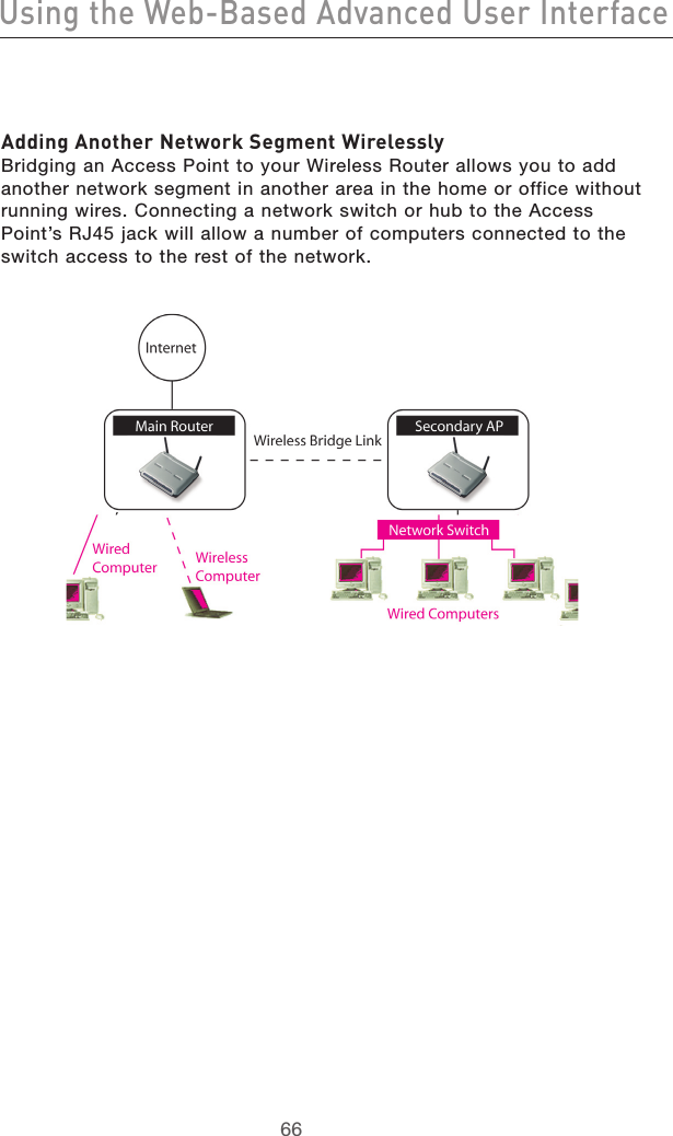
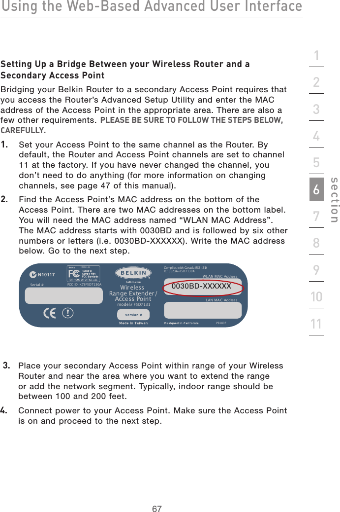
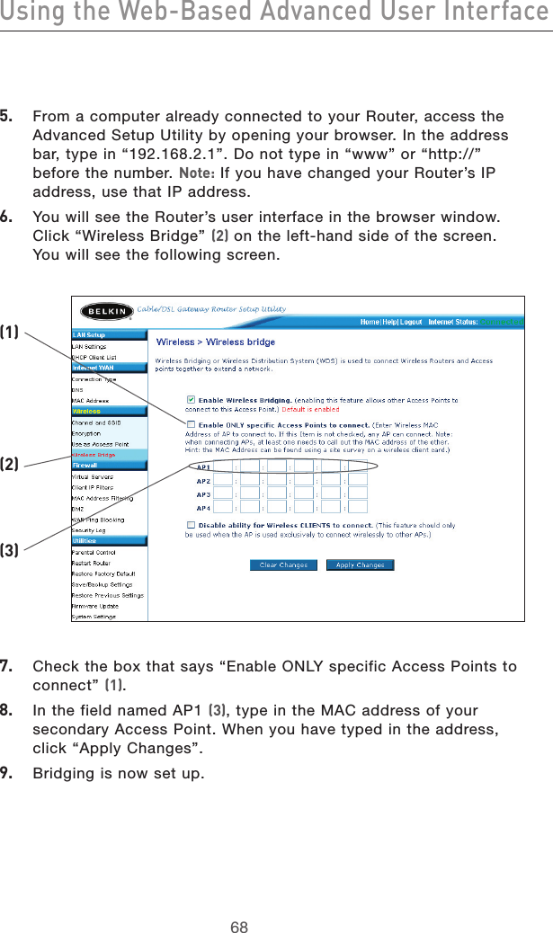
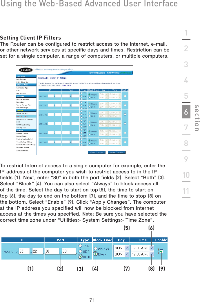
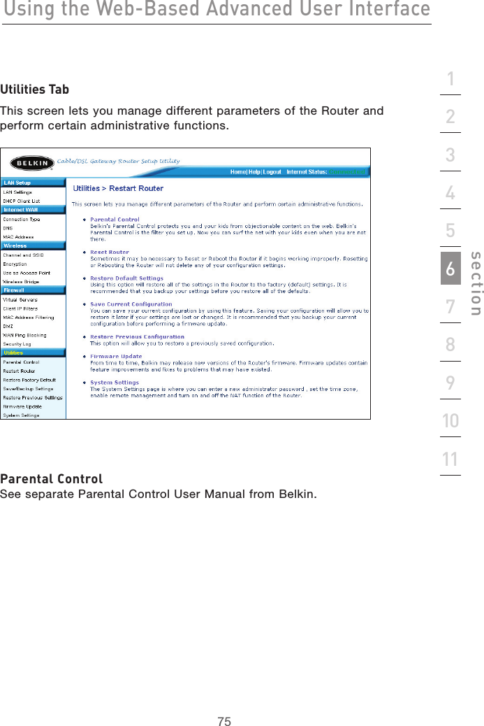
![7170Using the Web-Based Advanced User Interface7170Using the Web-Based Advanced User InterfaceConfiguring Internal Forwarding Settings The Virtual Servers function will allow you to route external (Internet) calls for services such as a web server (port 80), FTP server (Port 21), or other applications through your Router to your internal network. Since your internal computers are protected by a firewall, computers outside your network (over the Internet) cannot get to them because they cannot be “seen.” A list of common applications has been provided in case you need to configure the Virtual Server function for a specific application. If your application is not listed, you will need to contact the application vendor to find out which port settings you need.Choosing an Application Select your application from the drop-down list. Click “Add”. The settings will be transferred to the next available space in the screen. Click “Apply Changes” to save the setting for that application. To remove an application, select the number of the row that you want to remove then click “Clear”.Manually Entering Settings into the Virtual Server To manually enter settings, enter the IP address in the space provided for the internal (server) machine, the port(s) required to pass, select the port type (TCP or UDP), and click “Apply Changes”. Each inbound port entry has two fields with 5 characters maximum per field that allows a start and end port range, e.g. [xxxxx]-[xxxxx]. For each entry, you can enter a single port value by filling in the two fields with the same value (e.g. [7500]-[7500] or a wide range of ports (e.g. [7500]-[9000]). If you need multiple single port value or mixture of ranges and a single value, you must use multiple entries up to the maximum of 20 entries (e.g. 1. [7500]-[7500], 2. [8023]-[8023], 3. [9000]-[9000]). You can only pass one port per internal IP address. Opening ports in your firewall can pose a security risk. You can enable and disable settings very quickly. It is recommended that you disable the settings when you are not using a specific application.](https://usermanual.wiki/Delta-Electronics/F5D72304.Users-Manual-4/User-Guide-508005-Page-5.png)