Delta Electronics F5D72304 Wireless G Router User Manual P74688 F5D7230 4 1223 indd
Delta Networks, Inc. Wireless G Router P74688 F5D7230 4 1223 indd
Contents
Users Manual 4
6766
Using the Web-Based Advanced User Interface
6766
Using the Web-Based Advanced User Interface
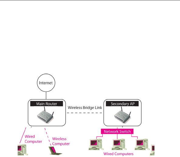
Adding Another Network Segment Wirelessly
Bridging an Access Point to your Wireless Router allows you to add
another network segment in another area in the home or office without
running wires. Connecting a network switch or hub to the Access
Point’s RJ45 jack will allow a number of computers connected to the
switch access to the rest of the network.
67
Using the Web-Based Advanced User Interface
67
section
2
1
3
4
5
6
7
8
9
10
11
Setting Up a Bridge Between your Wireless Router and a
Secondary Access Point
Bridging your Belkin Router to a secondary Access Point requires that
you access the Router’s Advanced Setup Utility and enter the MAC
address of the Access Point in the appropriate area. There are also a
few other requirements. PLEASE BE SURE TO FOLLOW THE STEPS BELOW,
CAREFULLY.
1. Set your Access Point to the same channel as the Router. By
default, the Router and Access Point channels are set to channel
11 at the factory. If you have never changed the channel, you
don’t need to do anything (for more information on changing
channels, see page 47 of this manual).
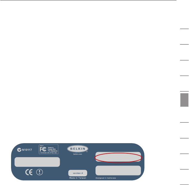
2. Find the Access Point’s MAC address on the bottom of the
Access Point. There are two MAC addresses on the bottom label.
You will need the MAC address named “WLAN MAC Address”.
The MAC address starts with 0030BD and is followed by six other
numbers or letters (i.e. 0030BD-XXXXXX). Write the MAC address
below. Go to the next step.
3. Place your secondary Access Point within range of your Wireless
Router and near the area where you want to extend the range
or add the network segment. Typically, indoor range should be
between 100 and 200 feet.
4. Connect power to your Access Point. Make sure the Access Point
is on and proceed to the next step.
FCC ID: K7SF5D7130A
model # F5D7131
Wireless
Range Extender/
Access Point
IC: 3623A-F5D7130A
Complies with Canada RSS-210
P81807
F5D7131
WLAN MAC Address
Ser ial #
LAN MA C Address
0030BD-XXXXXX
6968
Using the Web-Based Advanced User Interface
6968
Using the Web-Based Advanced User Interface
5. From a computer already connected to your Router, access the
Advanced Setup Utility by opening your browser. In the address
bar, type in “192.168.2.1”. Do not type in “www” or “http://”
before the number. Note: If you have changed your Router’s IP
address, use that IP address.
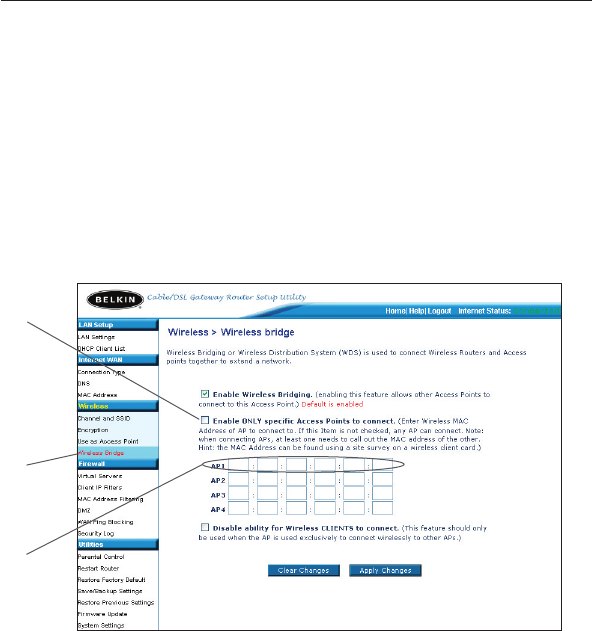
6. You will see the Router’s user interface in the browser window.
Click “Wireless Bridge” (2) on the left-hand side of the screen.
You will see the following screen.
7. Check the box that says “Enable ONLY specific Access Points to
connect” (1).
8. In the field named AP1 (3), type in the MAC address of your
secondary Access Point. When you have typed in the address,
click “Apply Changes”.
9. Bridging is now set up.
(1)
(2)
(3)
69
Using the Web-Based Advanced User Interface
69
section
2
1
3
4
5
6
7
8
9
10
11
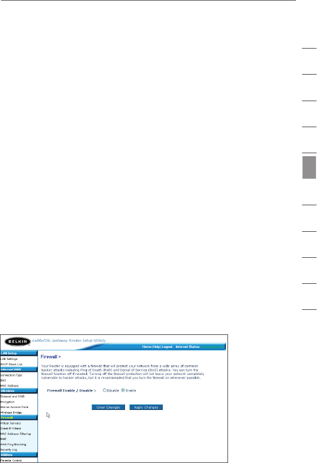
Configuring the Firewall
Your Router is equipped with a firewall that will protect your network
from a wide array of common hacker attacks including:
• IP Spoofing
• SYN flood
• Land Attack
• UDP flooding
• Ping of Death (PoD)
• Tear Drop Attack
• Denial of Service (DoS)
• ICMP defect
• IP with zero length
• RIP defect
• Smurf Attack
• Fragment flooding
• TCP Null Scan
The firewall also masks common ports that are frequently used to
attack networks. These ports appear to be “Stealth”, meaning that for
all intents and purposes, they do not exist to a would-be hacker. You
can turn the firewall function off if needed, however, it is recommended
that you leave the firewall enabled. Disabling the firewall protection will
not leave your network completely vulnerable to hacker attacks, but it
is recommended that you leave the firewall enabled.
7170
Using the Web-Based Advanced User Interface
7170
Using the Web-Based Advanced User Interface
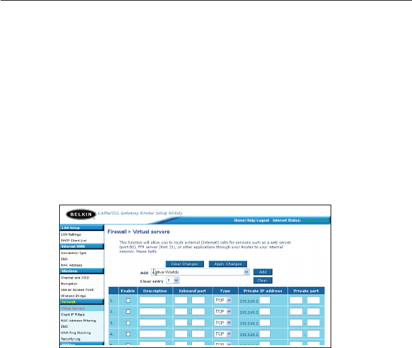
Configuring Internal Forwarding Settings
The Virtual Servers function will allow you to route external (Internet)
calls for services such as a web server (port 80), FTP server (Port 21),
or other applications through your Router to your internal network.
Since your internal computers are protected by a firewall, computers
outside your network (over the Internet) cannot get to them because
they cannot be “seen.” A list of common applications has been
provided in case you need to configure the Virtual Server function for
a specific application. If your application is not listed, you will need to
contact the application vendor to find out which port settings you need.
Choosing an Application
Select your application from the drop-down list. Click “Add”. The
settings will be transferred to the next available space in the screen.
Click “Apply Changes” to save the setting for that application. To
remove an application, select the number of the row that you want to
remove then click “Clear”.
Manually Entering Settings into the Virtual Server
To manually enter settings, enter the IP address in the space provided
for the internal (server) machine, the port(s) required to pass, select the
port type (TCP or UDP), and click “Apply Changes”. Each inbound port
entry has two fields with 5 characters maximum per field that allows a
start and end port range, e.g. [xxxxx]-[xxxxx]. For each entry, you can
enter a single port value by filling in the two fields with the same value
(e.g. [7500]-[7500] or a wide range of ports (e.g. [7500]-[9000]). If you
need multiple single port value or mixture of ranges and a single value,
you must use multiple entries up to the maximum of 20 entries (e.g.
1. [7500]-[7500], 2. [8023]-[8023], 3. [9000]-[9000]). You can only pass
one port per internal IP address. Opening ports in your firewall can
pose a security risk. You can enable and disable settings very quickly.
It is recommended that you disable the settings when you are not using
a specific application.
71
Using the Web-Based Advanced User Interface
71
section
2
1
3
4
5
6
7
8
9
10
11
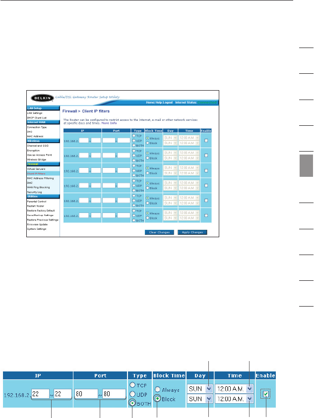
Setting Client IP Filters
The Router can be configured to restrict access to the Internet, e-mail,
or other network services at specific days and times. Restriction can be
set for a single computer, a range of computers, or multiple computers.
To restrict Internet access to a single computer for example, enter the
IP address of the computer you wish to restrict access to in the IP
fields (1). Next, enter “80” in both the port fields (2). Select “Both” (3).
Select “Block” (4). You can also select “Always” to block access all
of the time. Select the day to start on top (5), the time to start on
top (6), the day to end on the bottom (7), and the time to stop (8) on
the bottom. Select “Enable” (9). Click “Apply Changes”. The computer
at the IP address you specified will now be blocked from Internet
access at the times you specified. Note: Be sure you have selected the
correct time zone under “Utilities> System Settings> Time Zone”.
(1) (2) (3) (4) (7) (8) (9)
(5) (6)
7372
Using the Web-Based Advanced User Interface
7372
Using the Web-Based Advanced User Interface
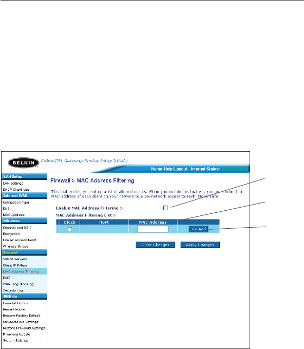
Setting MAC Address Filtering
The MAC address filter is a powerful security feature that allows you
to specify which computers are allowed on the network. Any computer
attempting to access the network that is not specified in the filter list
will be denied access. When you enable this feature, you must enter
the MAC address of each client (computer) on your network to allow
network access to each. The “Block” feature lets you turn on and off
access to the network easily for any computer without having to add
and remove the computer’s MAC address from the list.
To enable this feature, select “Enable MAC Address Filtering” (1).
Next, enter the MAC address of each computer on your network by
clicking in the space provided (2) and entering the MAC address of
the computer you want to add to the list. Click “Add” (3), then “Apply
Changes” to save the settings. To delete a MAC address from the list,
simply click “Delete” next to the MAC address you wish to delete. Click
“Apply Changes” to save the settings.
Note: You will not be able to delete the MAC address of the computer
you are using to access the Router’s administrative functions (the
computer you are using now).
(1)
(2)
(3)
73
Using the Web-Based Advanced User Interface
73
section
2
1
3
4
5
6
7
8
9
10
11
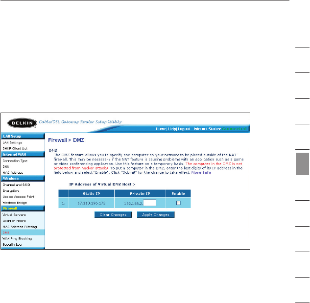
Enabling the Demilitarized Zone (DMZ)
The DMZ feature allows you to specify one computer on your network
to be placed outside of the firewall. This may be necessary if the
firewall is causing problems with an application such as a game or
video conferencing application. Use this feature on a temporary basis.
The computer in the DMZ is NOT protected from hacker attacks.
To put a computer in the DMZ, enter the last digits of its IP address in
the IP field and select “Enable”. Click “Apply Changes” for the change
to take effect. If you are using multiple static WAN IP addresses, it is
possible to select which WAN IP address the DMZ host will be directed
to. Type in the WAN IP address you wish the DMZ host to direct to,
enter the last two digits of the IP address of the DMZ host computer,
select “Enable” and click “Apply Changes”.
7574
Using the Web-Based Advanced User Interface
7574
Using the Web-Based Advanced User Interface
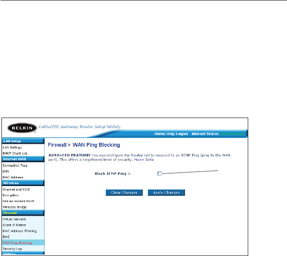
Blocking an ICMP Ping
Computer hackers use what is known as “pinging” to find potential
victims on the Internet. By pinging a specific IP address and receiving
a response from the IP address, a hacker can determine that something
of interest might be there. The Router can be set up so it will not
respond to an ICMP ping from the outside. This heightens the level of
security of your Router.
To turn off the ping response, select “Block ICMP Ping” (1) and click
“Apply Changes”. The Router will not respond to an ICMP ping.
(1)
75
Using the Web-Based Advanced User Interface
75
section
2
1
3
4
5
6
7
8
9
10
11
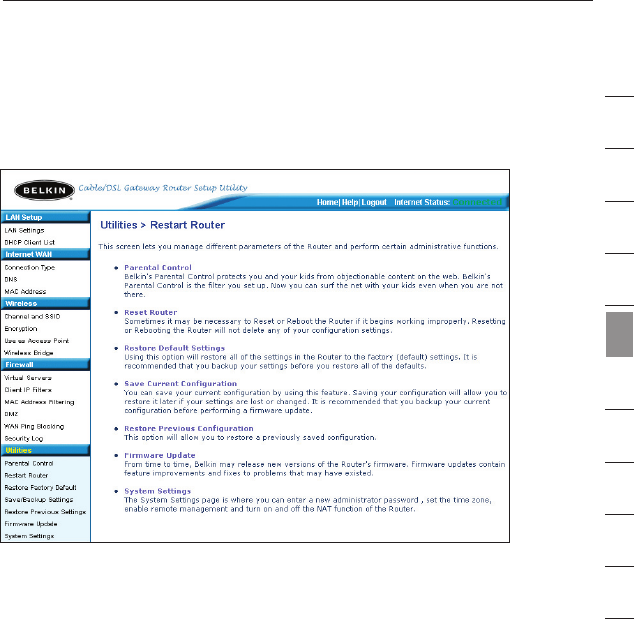
Utilities Tab
This screen lets you manage different parameters of the Router and
perform certain administrative functions.
Parental Control
See separate Parental Control User Manual from Belkin.