Delta Electronics TYPEIII 802.11b/g WiFi Module User Manual TYPE III UserMan Revised 1220 p
Delta Networks, Inc. 802.11b/g WiFi Module TYPE III UserMan Revised 1220 p
Contents
- 1. Users Manual 1 of 2
- 2. Users Manual 2 of 2
Users Manual 1 of 2
ProST
IEEE802.11b/g WiFi Board
Preliminary Reference Guide
Rev: 1.00
Date: August 31, 2005
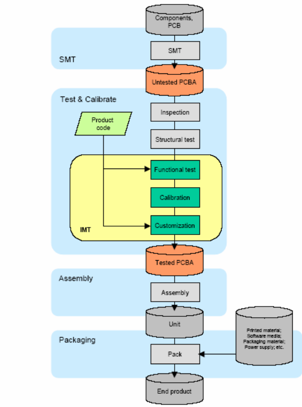
Total Manufacturing Test Process Overview:
In general the following steps are considered part of a manufacturing (test) flow:
1. PCBA assembly
2. Inspection(visual, automated visual, X-ray, )
3. Structural test of the digital circuitry(Boundary Scan Test (BST), or other
methods)
4. Functional test of the analog circuitry (radio test).
5. Calibration of the radio (for optimal performance within legal bounds); storing the
results to non-volatile memory.
6. Customization/ serialization (adding identity such as Part number to the DUT).
7. Plastics assembly.
8. Pack & ship.
Figure 1. Manufacturing Test Process
Manufacturing Test Plan Overview for IMT tool
1. Test initialization and Product identification
PCB serial number, product part number, and MAC address are established.
A bar code scanner or the keyboard can be used to enter this information
By default the information is divided between two codes. The first (bar) code
contains the PCB serial number. The second bar code contains the product part
number and half the Mac address.
2. DUT insertion
Depending on the type of DUT, the software waits for the DUT to be attached to
the set-up. If the DUT is not responding, the user is offered an escape by pressing
the ABORT button.
Alternatively the user is asked to insert the DUT and press the NEXT button. The
software then switches the DUT on, and continues with the testing.
3. System test
Properties of the operating system, including the version number, are determined
and tested for compatibility. The versions of a number of DLLs and other system
files are checked for compatibility as well.
4. Firmware and Driver Compatibility test
The MTFW version number is tested for compatibility.
5. Transmitter verification
A quick test is performed to verify the transmit function of the DUT. If the DUT
passes this test, the following is true: the test system can communicate with the
DUT firmware. The DUT can transmit RF signals with approximately the right
frequency and amplitude.
6. Frequency accuracy
The carrier frequency accuracy of the DUT is determined at the center channel.
The sum of the measured deviation plus the maximum instrument error must be
less than the limit set by the 802.11 standard
7. Receiver verification
The capability of the receiver circuitry to receive and demodulate 802.11 packets
is verified. If the DUT passes, the following is true: the receiver functions
correctly and the receiver sensitivity(PER) is within limits.
As part of this test the GRT output power is measured, the RF isolation between
GRT and DUT is verified, and interference from other 802.11 sources is detected.
8. RSSI calibration (linear approximation)
Linear curve fitting is performed on the result, and PDR 0x1902, 0x1905, or
0x1908 is calculated, depending on the platform type.
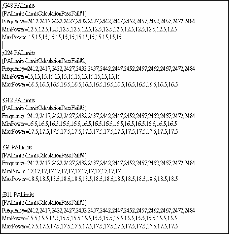
9. PA control loop calibration
The PA control loop behavior is measured as a function of modulation type (bit
rate) and channel (frequency). Depending on the platform, PDR 0x1901 or
0Xpdr1903 and 0x1904 are calculated.
There are two implementations for this step:
1. PA Calibration
2. PA Curves and PA limits
Besides, we have max/min output power pass/fail criteria for different
modulation as Figure2 in 9301A_param configured file.
Figure2. Power Limit
10. TX IQ Calibration
For the platforms that require it, ZIF TX IQ Calibration is performed.
11. NV initialize
By default this test will (re-)initialize and therefore erase the non-volatile
memory.
12. Upload files to flash
Files can be uploaded to AP based products. These files can contain firmware
images, boot loaders or custom made images.
13. Write PDA
The PDRs that were generated by the other test modules are written to the PDA
that resides in the non-volatile memory of the DUT.
802.11b/g WiFi Module
Features
The features supported by the ProST 802.11g WLAN Access Point are outlined below:
Interfaces directly to 10/100Mbps IEEE 802.3 Ethernet networks
Supports IEEE 802.11 WLAN functions
Supported WLAN Bridge function (WDS: Wireless Distribution System)
Firmware is stored in a flash memory and can be upgraded remotely.
Configurable through Web based management.
Power, Ethernet and wireless activity LED indicators.
One external and one internal inverted F antennas supporting diversity.
Wireless Network Configuration
Ad-hoc Mode (Peer-to-Peer Workgroup)
The Institute of Electrical and Electronics Engineers (IEEE) standard for wireless LANs (WLANs), 802.11, offers two
methods for configuring a wireless network — ad hoc and infrastructure. In an ad hoc network, computers are
brought together as needed; thus, there is no structure or fixed points to the network — each node can generally
communicate with any other node. There is no access point involved in this configuration. It enables you to quickly
set up a small wireless workgroup and allows workgroup members to exchange data or share printers as supported by
Microsoft Networking in the various Windows operating systems. Some vendors also refer to ad hoc networking as
Peer-to-Peer group networking.
In this configuration, network packets are directly sent and received by the intended transmitting and receiving stations.
As long as the stations are within range of one another, this is the easiest and least expansive way to set up a wireless
network.
To set up an ad hoc workgroup operating with standard protocols, do the following:
•Set all stations to connect in Ad-hoc mode (or Peer-to-Peer workgroup mode)
•Set all stations to use the same network name (or SSID).
•Set all stations to use no WEP encryption key or an identical WEP encryption key
•Set all stations to use the same wireless channel for communication
Infrastructure Mode
To set up an infrastructure network operating with standard protocols, do the following:
• Set all wireless stations to connect in infrastructure mode
• Set all stations to use the same network name (or SSID)
• Set all stations to use no WEP encryption key or an identical WEP encryption key
• Set up wireless channels used by individual access point. (It is not necessary to set channels on the stations as
the stations will automatically scan through all channels for the nearest access point.)

802.11b/g WiFi Module
Service Set Identification (SSID)
The Service Set Identification (SSID) is a thirty-two alphanumeric character (maximum) string identifying the wireless
local area network (WLAN). Some vendors refer to the SSID as network name. For stations to communicate with
each other, all stations must be configured with the same SSID.
Authentication and WEP Encryption
The absence of a physical connection between nodes makes the wireless links vulnerable to information theft. To
provide certain level of security, IEEE 802.11 standard has defined two types of authentication methods, Open System
and Shared Key. Open System authentication is a null algorithm. Shared Key authentication is an algorithm where
both the transmitting node and the receiving node share an authentication key to perform a checksum on the original
message. By default, IEEE 802.11 wireless devices operate in an open system network.
Wired Equivalent Privacy (WEP) data encryption is utilized when the wireless nodes or access points are configured to
operate in Shared Key authentication mode. There are two shared key methods implemented in most commercially
available products, 40-bit WEP data encryption and 104-bit WEP data encryption.
The 40-bit WEP data encryption method allows for a five-character (forty -bit) input. Additionally, 24 factory-set bits
are added to the forty -bit input to generate a 64-bit encryption key. (The 24 factory-set bits are not user configurable.)
This encryption key will be used to encrypt/decrypt all data transmitted via the wireless interface. Some vendors may
refer to the 40-bit WEP data encryption as 64-bit WEP data encryption since the actual encryption key used in the
encryption process is 64 bits wide.
The 128-bit WEP data encryption method consists of 104 configurable bits. Similar to the 40-bit WEP data encryption
method, the remaining 24 bits are factory set and not user configurable. Some vendors allow pass phrases to be
entered instead of the cryptic hexadecimal characters to ease encryption key entry.
Wireless Channel Selection
IEEE 802.11g wireless nodes communicate with each other using radio frequency signals in the ISM (Industrial,
Scientific, and Medical) band between 2.4Ghz and 2.5Ghz. Neighboring channels are 5Mhz apart. However, due
to spread spectrum effect of the signals, a node sending signals using a particular channel will utilize frequency
spectrum12.5Mhz above and below the center channel frequency. As a result, two separate wireless networks using
neighboring channels (for example, channel 1 and channel 2) in the same general vicinity will interfere with each other.
Applying two channels that allow the maximum channel separation will decrease the amount of channel cross talk, and
provide a noticeable performance increase over networks with minimal channel separation.
Channel Center Frequency Frequency Spread
1 2412Mhz 2399.5Mhz – 2424.5Mhz
2 2417Mhz 2404.5Mhz – 2429.5Mhz
3 2422Mhz 2409.5Mhz –2434.5Mhz
4 2427Mhz 2414.5Mhz –2439.5Mhz
5 2432Mhz 2419.5Mhz – 2444.5Mhz
6 2437Mhz 2424.5Mhz –2449.5Mhz
7 2442Mhz 2429.5Mhz –2454.5Mhz
8 2447Mhz 2434.5Mhz – 2459.5Mhz
9 2452Mhz 2439.5Mhz –2464.5Mhz
10 2457Mhz 2444.5Mhz –2469.5Mhz
11 2462Mhz 2449.5Mhz – 2474.5Mhz
12 2467Mhz 2454.5Mhz – 2479.5Mhz
13 2472Mhz 2459.5Mhz – 2484.5Mhz
802.11b/g WiFi Module
Note: The available channels supported by the wireless products in various countries are different by
firmware.
The preferred channel separation between the channels in neighboring wireless networks is 25 MHz (5 channels).
This means that you can apply up to three different channels within your wireless network. There are only 11 usable
wireless channels in the United States. It is recommended that you start using channel 1 and grow to use channel 6,
and 11 when necessary.
Changing Wireless Parameters
The following table explains each of the configurable parameters of the ProST WLAN Device.
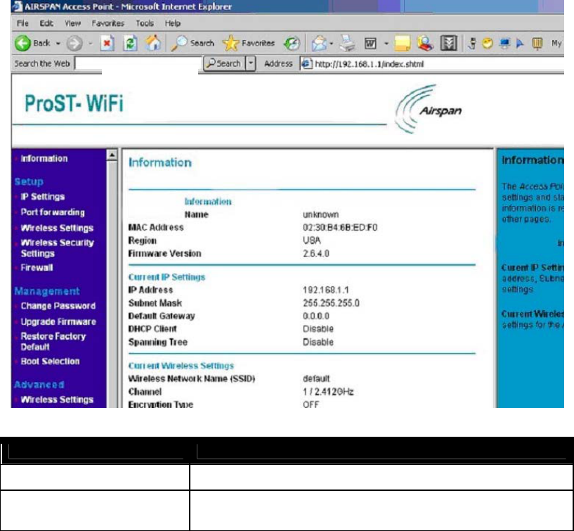
System Information
The System Information shows current ProST information.
System Information Model ProST WLAN Access Point
Name Default DUT name
MAC Address Displays the six-byte MAC address of the access point. This parameter is not
changeable by the user.

802.11b/g WiFi Module
Region Define the regulatory domain of the operation area (default: US)
Firmware Version 2.6.4.0
IP Address Assign Internet Protocol (IP) address to the access point.
Subnet Mask Assign IP Subnet Mask to the access point.
Default Gateway Assign default Gateway to the access point if needed
DHCP Client Dynamic Host Configuration Protocol, it allows to request the IP from DHCP
server for all wireless clie nts.
Wireless Network Name (SSID) Enter a 32-character (maximum) extended service set ID in this field. The
characters are case sensitive. With an access point, the wireless network
always functions in infrastructure mode. The SSID assigned to the wireless
nodes in the same network is required to match the access point SSID. The
default SSID is “default.
Channel In infrastructure mode, the wireless node automatically searches through all
available wireless channels for an access point to be associated with. It is
not necessary to select the wireless channel when operating in infrastructure
mode. The default wireless channel is 1.
Encryption Type Show encryption type OFF, WEP, 802.1X, or WPA.
Access Control Show Access Control Enable, Disable or Block
Setup
.
IP Setting
IP Settings MODEL ProST WLAN ACCESS POINT
Name The default Access Point Name is located on the bottom label of the product. You may
modify the default name with a unique name up to 15 characters long.
DHCP client When there is DHCP Server on the network, if you will manually configure this device,
check the “Disable” check box. Otherwise, check the “Enable” check box, and you need
enter the next three items below correctly.
IP Address Assign Internet Protocol (IP) address to the access point.
IP subnet mask Assign IP Subnet Mask to the access point.
Default Gateway Assign default Gateway to the access point if needed
Spanning Tree Protocol Spanning-Tree Protocol is a link management protocol that provides path redundancy
while preventing undesirable loops in the network. You can enable it to gain the
function.
802.11b/g WiFi Module
Apply Means once you change the parameters and save the values
Cancel Means you leave it un-changed
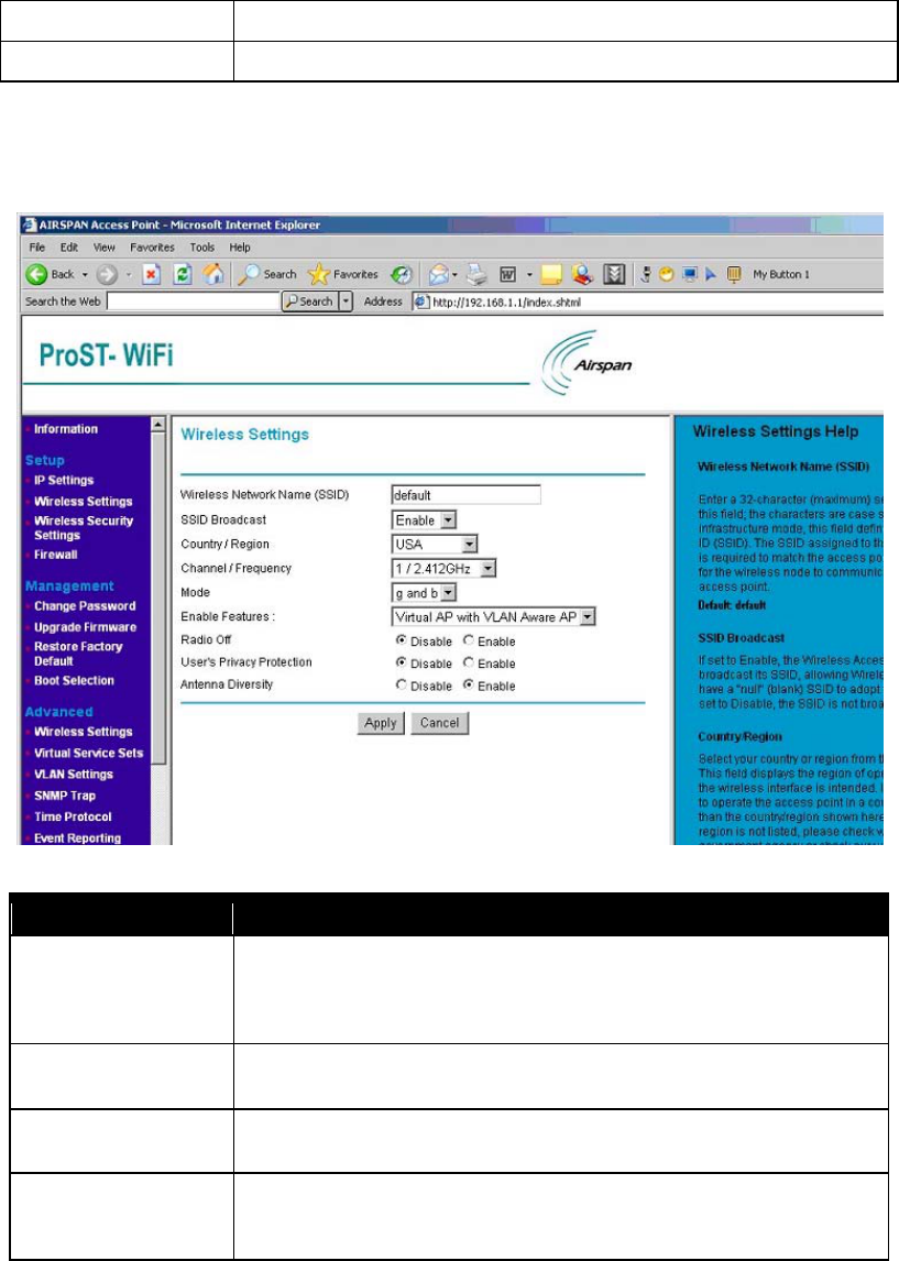
Wireless Settings
Wireless Settings MODEL ProST WLAN Device
Wireless Network Name
(SSID)
Enter a 32-character (maximum) extended service set ID in this field. The characters
are case sensitive. With an access point, the wireless network always functions in
infrastructure mode. The SSID assigned to the wir eless nodes in the same network
is required to match the access point SSID. The default SSID is “ default” .
SSID Broadcast Every Client can detect the AP if we check “Enable”, otherwise, it can’t be detected
automatically.
Country/Region Define the regulatory domain of the operation area (default: None). User may need to
choose one of the areas from pop up menu.
Channel/Frequency In infrastructure mode, the wireless node automatically searches through all available
wireless channels for an access point to be associated with. It is not necessary to
select the wireless channel when operating in infrastructure mode The default
802.11b/g WiFi Module
wireless channel is 1.
Mode B or/and G mode can be selected. With “ B only” , the speed is under 11Mbps; with “ G
mode” or “ B and G mode” , the speed is up to 54Mbps.
Enable Features When choose “ WMM with VLAN PassThru” , you can have this function, but you can’ t
gain the function of “ Virtual AP with VLAN Aware AP” . Vice versa.
Radio Off When enable it, means the radio is off and the AP won’ t be scanned. Otherwise, you
can find it.
User's Privacy Protection When enabled, the signal from different users won’ t be interfered.
Antenna Diversity When enabled, the AP can automatically choose the more appropriate antenna for
signal sending.
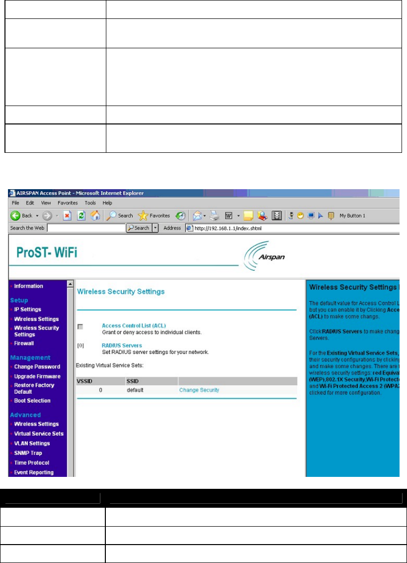
Security Setting
Security Settings
Access Control List (ACL) Grant or deny access to individual clients. Click it to make some changes.
RADIUS Servers Set RADIUS server settings for your network. Click it to make changes.
Existing Virtual Service Sets Change Security. Click “ Change Security” to make changes to the corresponding SSID.
802.11b/g WiFi Module
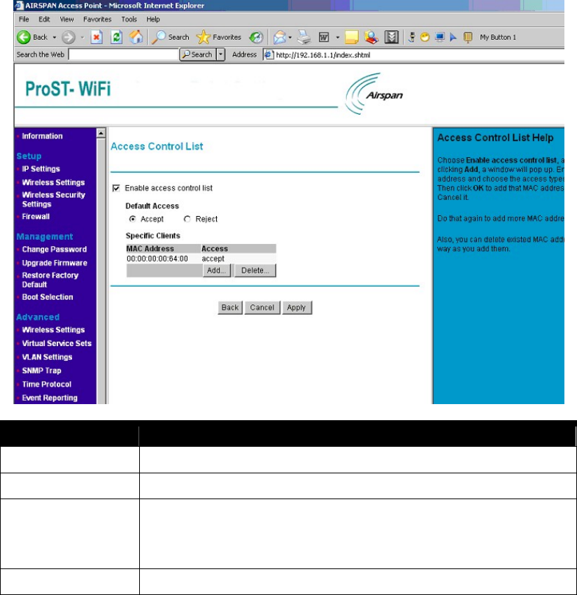
Access Control List (ACL)
Security Settings
Enable access control list Default is disabled. Choose it to enable items below.
Default Access Choose the default access policy is “ Accept” or “ Reject”
Specific Clients Configure specific clients. You can add or delete these clients. Click “ Add” and a window
will pop up. Enter the MAC address and choose the access types (accept or reject). Then
click OK to add that MAC Address to the system, or Cancel it.
Also, you can delete existed MAC addresses the same way as you add them.
Back Back to the “ Wireless Security Settings” .
802.11b/g WiFi Module
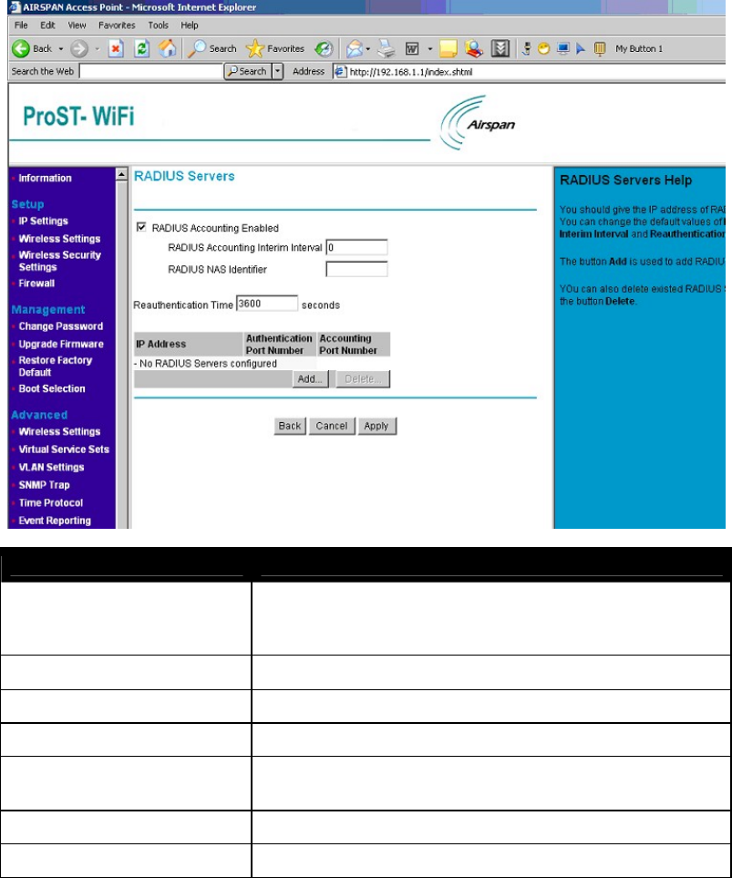
RADIUS Servers
Security Settings
RADIUS RADIUS can enables remote access servers to communicate with a central
server to authenticate dial-in users and authorize their access to the
requested system or service.
RADIUS Accounting Interim Interval How often should the RADIUS Account function take place
RADIUS NAS Identifier Enter the IP Address of NAS, which is used for accounting.
Reauthentication How often should the AP authentication again
Add Used to add RADIUS Server(s). When clicked, a window will pop up.
Provide the correct IP Address for RADIUS Server and “ Secret” , then “ OK” .
Delete Delete existed RADIUS Server(s).
Back Back to the “ Wireless Security Settings” .
802.11b/g WiFi Module
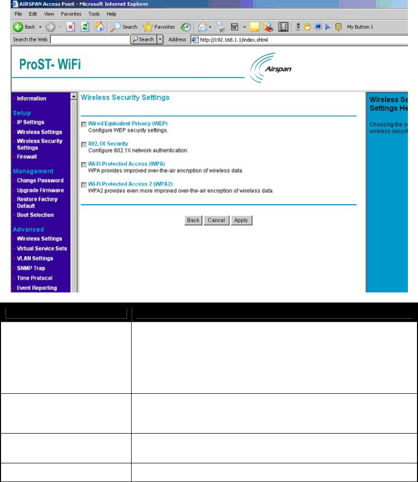
Change Security
Security Settings
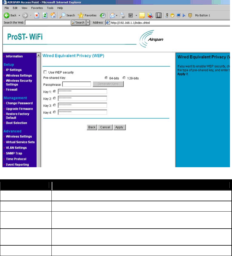
Wired Equivalent Privacy (WEP) Configure WEP security settings. Wired Equivalent Privacy (WEP) is a security
protocol, which designed to provide a wireless local area network (WLAN) with a
level of security and privacy comparable to what is usually expected of a wired
LAN. WEP seeks to establish similar protection to that offered by the wired
network's physical security measures by encrypting data transmitted over the
WLAN.
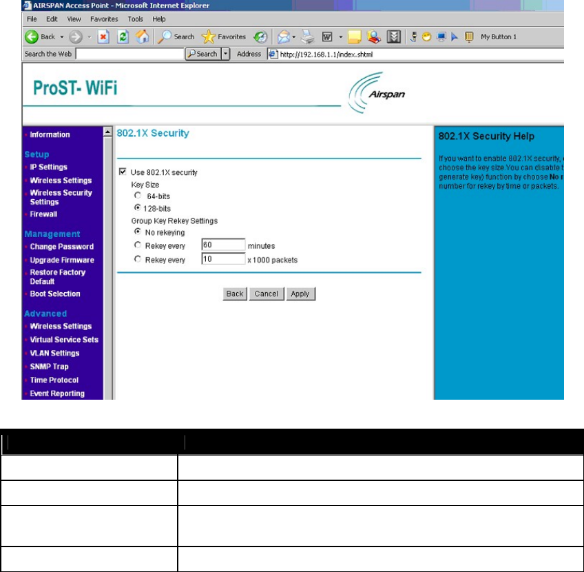
802.1X Security Configure 802.1X network authentication. 802.1X provides an authentication
framework for wireless LANs, allowing a user to be authenticated by a central
authority.
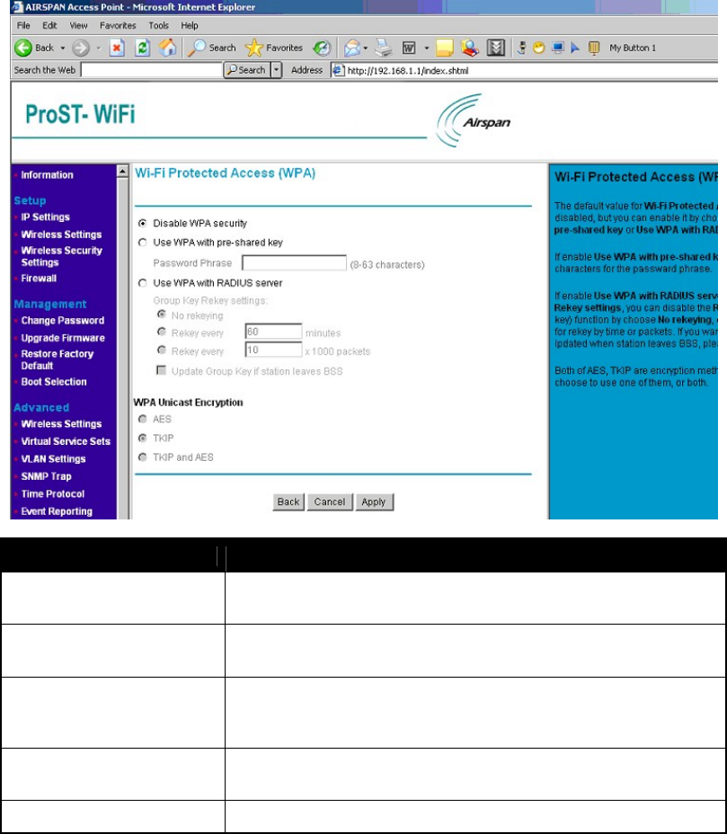
Wi-Fi Protected Access (WPA) WPA provides improved over-the-air encryption of wireless data. It was designed
to improve upon the security features of WEP.
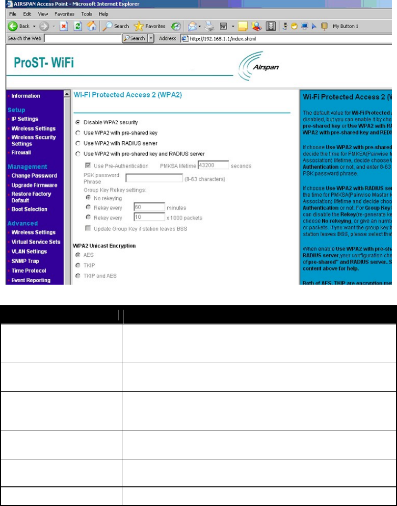
Wi-Fi Protected Access 2 (WPA2) WPA2 provides even more improved over-the-air encryption of wireless data.
802.11b/g WiFi Module
WEP
Security Setting
Use WEP security Choose it to enable the WEP function.
Pre-shared Key To define the encryption strength
Passphrase Used to generate the keys. Enter a passphrase and click the "Generate Keys" button. You
can also enter the keys directly. These keys must match the other wireless stations.
Key 1/2/3/4 It is produced after clicking “ Generate Keys” . The stations need these keys to connect this
AP.
Back Back to the “ Wireless Security Settings” .
802.11b/g WiFi Module
802.1X Security
Security Setting
Use 802.1X security Choose it to enable the 802.1X function.
Key Size How many bits will be provided to 802.1X.
Group Key Rekey Settings Rekey means “ re-generate key” ; You can choose “ No rekeying” , or give an number for
rekey by time or by packets.
Back Back to the “ Wireless Security Settings” .
Wi-Fi Protected Access (WPA)
802.11b/g WiFi Module
Security Setting
Wi-Fi Protected Access (WPA) You can choose “ Disable WPA security” or “ Use WPA with pre-shared key” or
“ Use WPA with RADIUS server” .
Use WPA with pre-shared key If AP shares a key earlier with stations, enter it below. The key should between 8
and 63 characters.
Use WPA with RADIUS server Rekey means “ re-generate key” ; You can choose “ No rekeying” , or give a
number for rekey by time or by packets. If you want to update group key when
station(s) leaves BSS, please choose it.
WPA Unicast Encryption Both of AES, TKIP are encryption methods. You can choose to use one of them,
or both.
Back Back to the “ Wireless Security Settings” .
802.11b/g WiFi Module
Wi-Fi Protected Access 2 (WPA2)
Security Setting
Wi-Fi Protected Access 2 (WPA2) You can choose “ Disable WPA2 security” , “ Use WPA2 with pre-shared key” ,
“ Use WPA2 with RADIUS server” or “ Use WPA2 with pre-shared key and
RADIUS server” .
Use WPA2 with pre-shared key If AP shares a key earlier with stations, enter it below. The key should between 8
and 63 characters.
Use WPA2 with RADIUS server Rekey means “ re-generate key” ; You can choose “ No rekeying” , or give a
number for rekey by time or by packets. If you want to update group key when
station(s) leaves BSS, please choose it.
Use WPA2 with pre-shared key
and RADIUS server
If choose it, give configurations for both of “ pre-shared key” and “ RADIUS
Server” , which is the same as above.
WPA2 Unicast Encryption Both of AES, TKIP are encryption methods. You can choose to use one of them,
or both.
Back Back to the “ Wireless Security Settings” .
802.11b/g WiFi Module
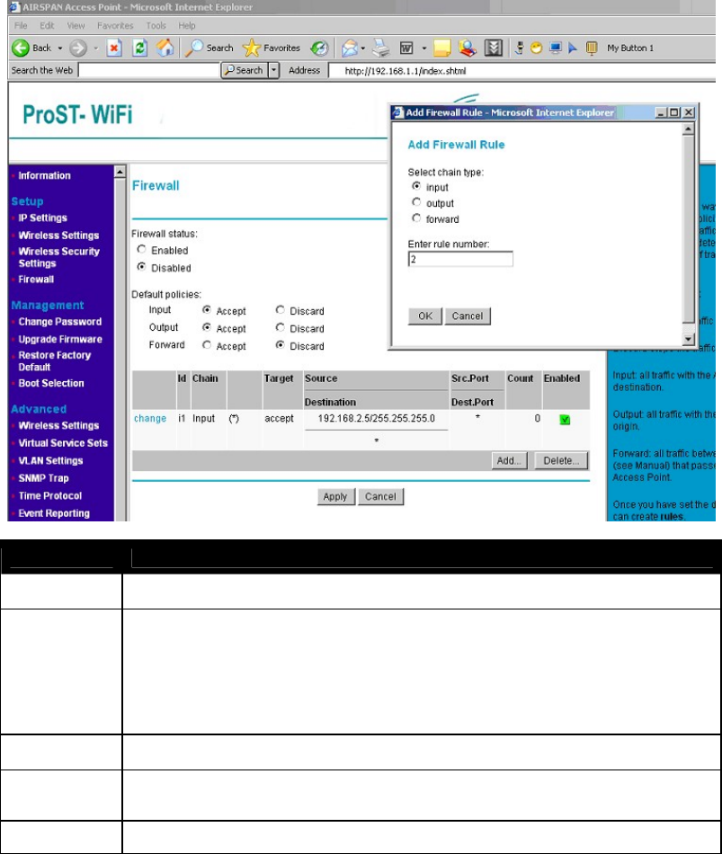
Firewall
Firewall
Firewall Default is “ Disable” . You should choose “ Enable” to make it works.
Default policies Accept sends the traffic through; Discard stops the traffic.
Input: all traffic with the Access Point as destination;
Output: all traffic with the Access Point as origin;
Forward: all traffic between LAN and WAN (see Manual) that passes through the Access Point.
Once you have set the default policies, you can create rules.
Change Change the properties of existed rules
Add "Chain type" is the direction of traffic.
"Rule Number" will be used to identify the rule and the order in which rules are applied.
Delete Delete existed rules
After clicked “ OK” , a pop window appears like below:
802.11b/g WiFi Module
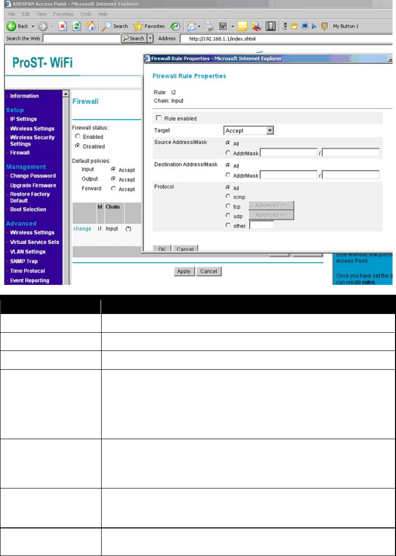
Firewall Rule
Rule Used to identify the rule and the order in which rules are applied.
Chain The direction of traffic.
Rule enabled Choose it to enable this firewall rule.
Target This tells the firewall what to do with the traffic that meets the conditions in this rule.
Accept: traffic will be allowed.
Drop: traffic will be stopped, with no response to the sender.
Reject: traffic will be stopped, and a response will be returned to the sender.
Continue: the traffic packet will be counted, and testing will continue with the next rule.
Use this if you only want to count packets.
Source Address/Mask Enter the IP address for the source. You can enter an address range by giving the
network (lowest) address and the net mask. Select the All radio button to choose 'all IP
Addresses'.
Destination Address/Mask Enter the IP address for the destination. You can enter an address range by giving the
network (lowest) address and the net mask. Select the All radio button to choose 'all IP
Addresses'.
Protocol Select the type of traffic you want to be affected by the rule. If you select TCP or UDP,
you can click Advanced to select a specific port number or port number range To set a