Delta Electronics TYPEIII 802.11b/g WiFi Module User Manual TYPE III UserMan Revised 1220 p
Delta Networks, Inc. 802.11b/g WiFi Module TYPE III UserMan Revised 1220 p
Contents
- 1. Users Manual 1 of 2
- 2. Users Manual 2 of 2
Users Manual 2 of 2
802.11b/g WiFi Module
port range, enter the first and last port number in the range into the edit boxes.
For TCP traffic, you can also select specific flags. Use this to block only incoming TCP
traffic (for example telnet), but allow outgoing (from LAN to WAN) traffic. To do this,
check the Match TCP flags check box, and set these flags: SYN radio button to Yes,
ACK to NO, RST to NO.
OK Save the rule and return.
Cancel Return without save the rule.
Management information
The Management Information shows:
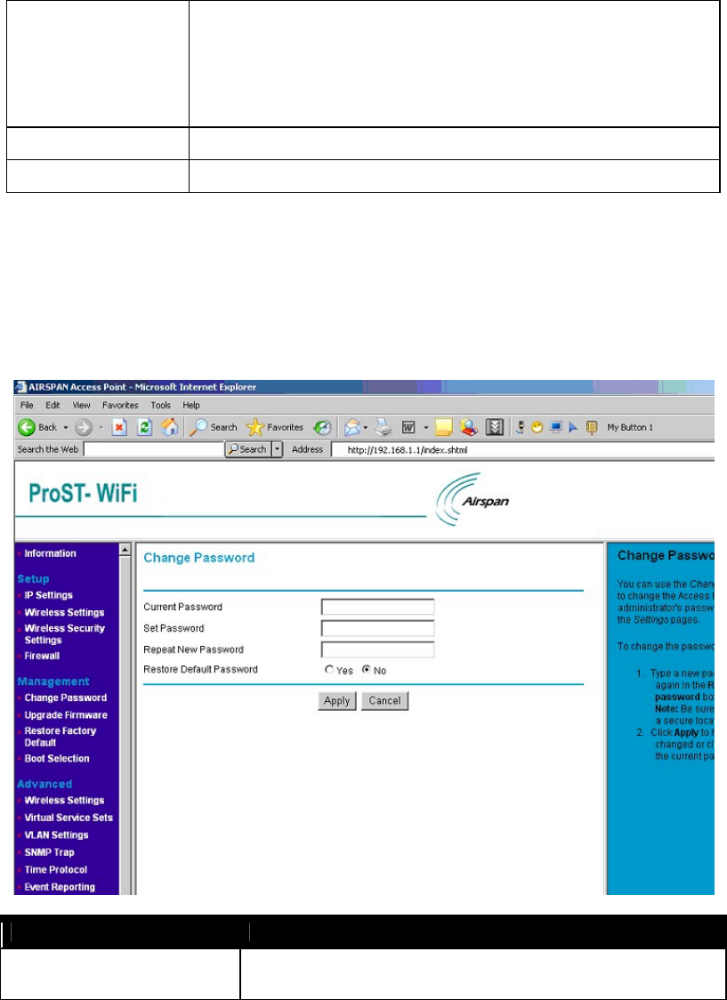
Change Password
Change Password
Current Password Users may need to enter the present password to allow change the new
password
802.11b/g WiFi Module
Set Password Users set a new password for this device
Repeat New Password To confirm your previous entry are identity characters
Restore Default Password To restore new password in the memory
Apply Means once you change the parameters and press apply to save the values.
Cancel Means you leave it un-changed.
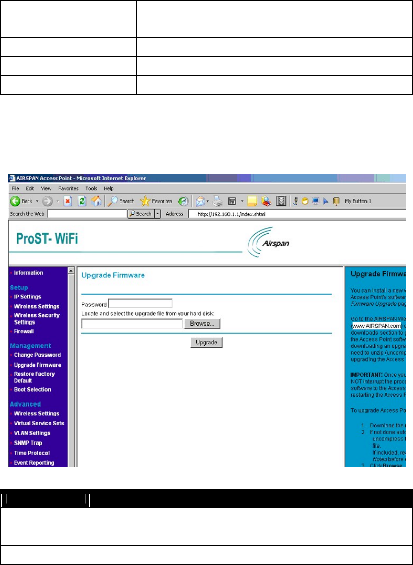
Upgrade Firmware
Upgrade Firmware
Password Used for upgrade.
Browse Users may define the upgraded file location on the system directory
Upgrade Press Upload for downloading the new firmware version on the device
802.11b/g WiFi Module
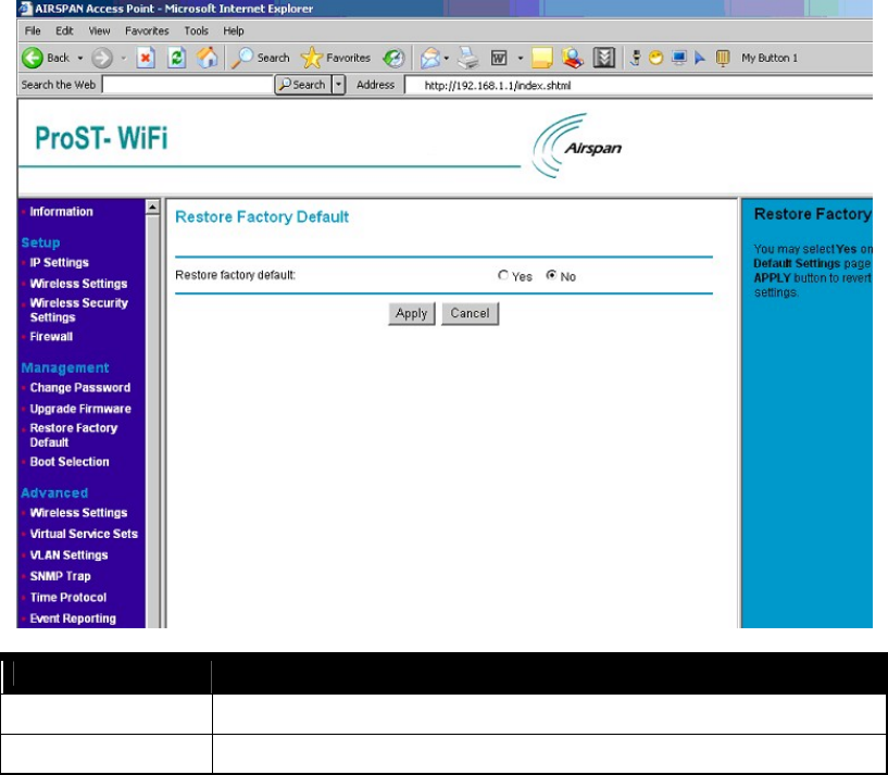
Restore Factory Default
Restore Factory Default
Restore factory default Users may call back the initial default setting parameters by select “ Yes” and click “ Apply” .
Cancel Means you leave it un-changed
802.11b/g WiFi Module
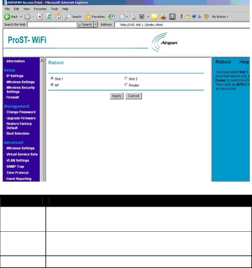
Boot Selection
Boot Selection
Slot 1, 2 There are two images of different releases in the flash. One stays at a place called Slot 1 while
another stays at Slot 2. They are non-relative with each other. You can choose one of them to
boot from.
Reboot AP You may select Slot 1 or Slot 2 to boot from that slot, and select AP or Router to boot to that
mode. Then click on “Apply” button to reboot the access point. It will boot from the Slot in the
mode from your choose; and it will always boot like this until you make different changes again.
Cancel Means you leave it un-changed.
802.11b/g WiFi Module
Advanced Configuration
Allow advanced users to set up RTS (Request to Send) Threshold packet size, Fragmentation Packet Length, Beacon
Interval, VSS, VLAN, snmp trap, time protocol and so on.
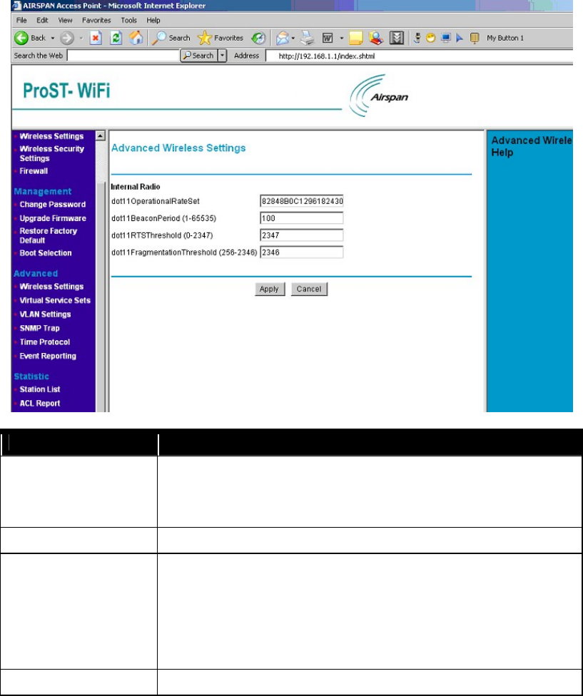
Wireless Settings
Advance Wireless Setting Model ProST WLAN Access Point
dot11OperationalRateSet It specifies the set of data rates at which the station may transmit data. Each octet
contains a value representing a rate. Each rate shall be within the range from 2 to 127,
corresponding to data rates in increments of 500 kb/s from 1 Mb/s to 63.5 Mb/s, and
shall be supported for receiving data.
dot11BeaconPeriod Specify the value for Beacon Interval. You can choose it between 1 and 65535.
dot11RTSThreshold The packet size that the wireless node uses to determine if it should use the
CSMA/CD mechanism or the CSMA/CA mechanism for packet transmission. With
the CSMA/CD transmission mechanism, the transmitting station sends out the actual
packet as soon as it has waited for the silence period. With the CSMA/CA
transmission mechanism, the transmitting station sends out a RTS packet to the
receiving station, waits for the receiving station to send back a CTS packet before
sending the actual packet data. You can choose it between 0 and 2347.
dot11FragmentationThreshold
This is the packet length used for fragmentation Packets large
r than the size
802.11b/g WiFi Module
programmed in this field will be fragmented. The Fragment Threshold value must be
larger than RTS Threshold value. You can choose it from 256 to 2346.
Apply Means once you change the parameters and press apply to save the values.
Cancel Means you leave it un-changed.
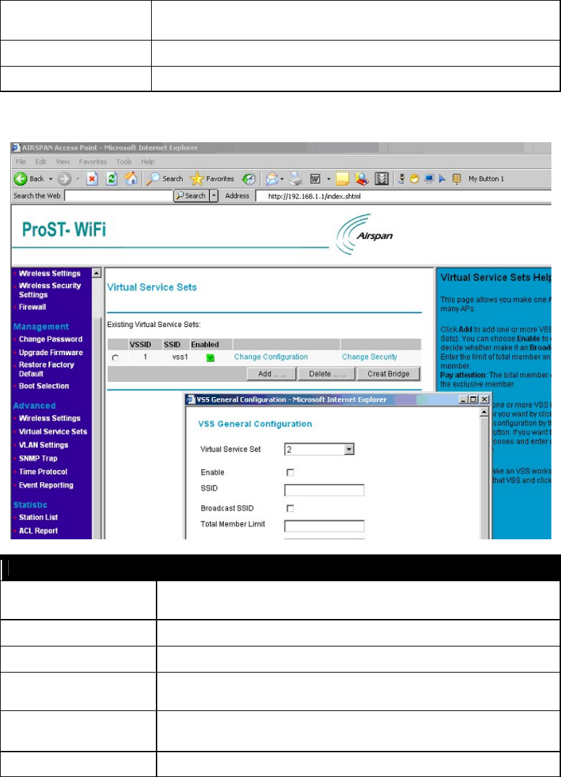
Virtual Service Sets
Virtual Service Sets
VSSID It indicates the VLAN number with which the frames are tagged when sent on a
VLAN.
SSID Set a wireless network name ( SSID: Service Set Identifier)
Enabled Indication the status of Virtual Service Sets (Enable)
Change Configuration Changes Virtual Service Sets on specified VLAN. Click it will pop up a window likes
the picture above with values filled.
Change Security Change the security configuration of Virtual Service Sets. You can consult “ Wireless
Security Settings” above for more details about security configuration.
Add
Add Virtual Service Sets on specify VLAN
Click it will pop up a window just the same

802.11b/g WiFi Module
as in the picture above.
Delete Delete existed Virtual Service Sets on specify VLAN.
Create Bridge If you want to make an VSS works as an bridge, please choose that VSS and click
“Create Bridge” .
VLAN Settings
VLAN Settings
VLAN Version Number Means which VLAN version is in use.
Maximum value of
VLANID Supported
The maximum value you can give to your VLAN as an ID. For it is 4094, you can’ t give a
value bigger than 4094 or less than 0.
Maximum number of
VLANs supported
How many VLANs your system can support. In this case, you can create no more than 32
ones.
Current number of VLANs How many VLANs you have now.
Select Select the Virtual LAN.
VLAN ID A VLAN number, packet with tagged when packet send
VLAN Name Name identifying the VLAN. Needs to be unique across the VLANS created.
802.11b/g WiFi Module
Tagged Ports Indicates the VLAN interfaces on which all packets will be received/transmitted tagged.
Untagged Ports Indicates the VLAN interfaces on which all untagged packets received, are transmitted to
the specified VLAN. Similarly any packet received on any other interface for this VLAN is
transmitted untagged on this interface.
Wireless Ports Indicate the wireless interfaces that are added on the VLAN such that any traffic received
on the wireless interface is transmitted to the corresponding VLAN on the appropriate
VLAN interface and any traffic received for this VLAN from the VLAN interface is
transmitted as untagged 802.11 frames on the wireless interface.
Add Add more VLANs:
VLAN ID : give a number between 1 and 4094 as the VLAN ID.
VLAN Name : give no more than 32 characters as the VLAN's name.
Tagged Ports : choose which port you'd like to act as a tagged port.
Untagged Ports : choose which port you'd like to act as a untagged port.
Wireless Ports :: choose which port you'd like to act as a wireless port.
Delete Delete existed VLANs.
Modify Change the configuration of selected VLAN.
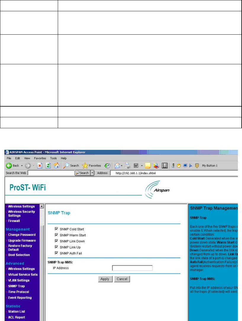
SNMP Trap
802.11b/g WiFi Module
SNMP Trap
SNMP Trap Cold Start: Generated when the system starting from power down state.
Warm Start: Generated when System restart without power down.
Link Down: Generated when the link state of a port is changed from up to down.
Link Up: Generated when the link state of a port is changed from down to up.
Auth Fail (Authentication Failure): Generated when the agent receives requests from
an unauthorized manager.
When selected, the trap will be sent in certain condition.
SNMP Trap NMS Fill in the IP Address of SNMP Trap NMS.
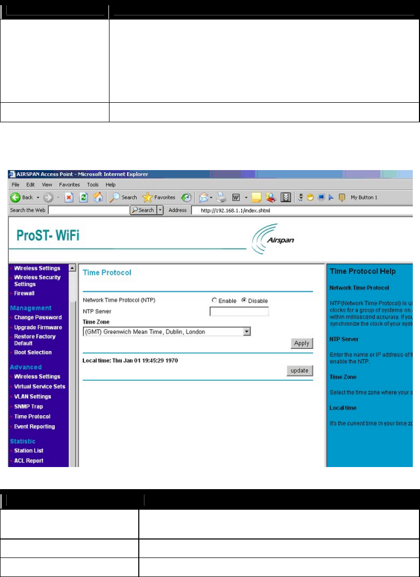
Time Protocol
Time Protocol
Network Time Protocol(NTP) Activate Network time (Enable/Disable). When enable it, You need provided
the NTP Server for it.
NTP Server Fill in the time server’s URL address or IP Address.
Time Zone Choose world time area.
802.11b/g WiFi Module
Update Once setup update current device.
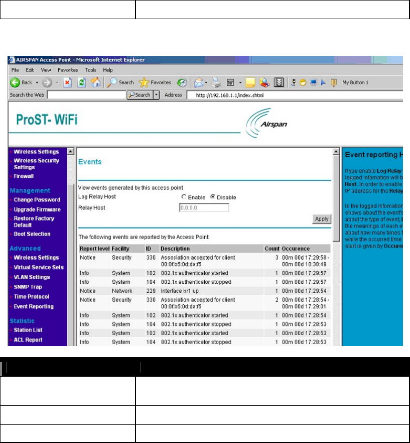
Events Reporting
Events
Log Relay Host Activate the Events log (Enable/Disable). When enabled, you need fill in the
Relay Host with correct IP Address.
Relay Host Fill in the host station IP address.
Apply Save your changes.
Statistic
Provide statistic data about Station List, ACL, CPU and memory usage, and so on.
802.11b/g WiFi Module
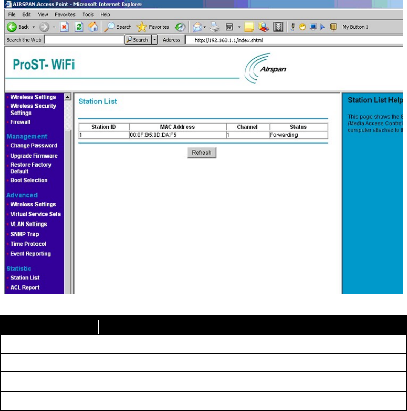
Station List
Station List
Station ID Shows the station ID which is associated with this AP
MAC Address Shows the MAC Address of the station which is associated with this AP
Channel Shows the Channel of the station which is associated with this AP
Status Shows the link status of the station which is associated with this AP
802.11b/g WiFi Module
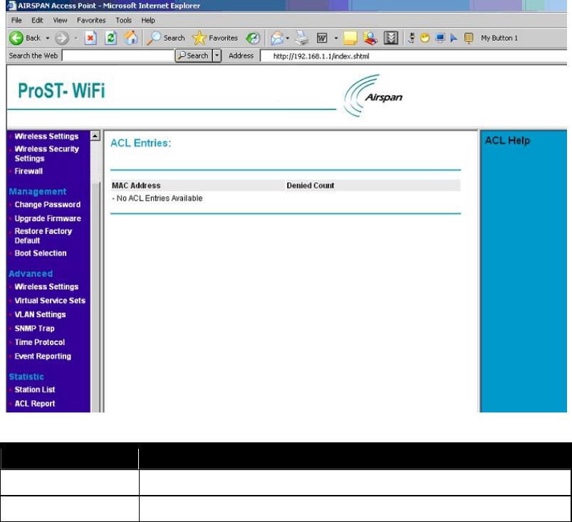
ACL Entries
ACL Entries
MAC Address Shows requests from these MAC Addresses will be denied.
Denied Count How many times the request from each MAC Address be denied.
802.11b/g WiFi Module
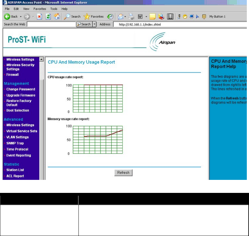
CPU And Memory Usage Report
CPU And Memory Usage Report
CPU And Memory Usage Report The two diagrams are used to illustrate the usage rate of CPU and memory.
Each of them draws a line from right to left in each diagram. The lines refreshed
in every three seconds.
When the Refresh button is clicked, the two diagrams will be refreshed.
802.11b/g WiFi Module
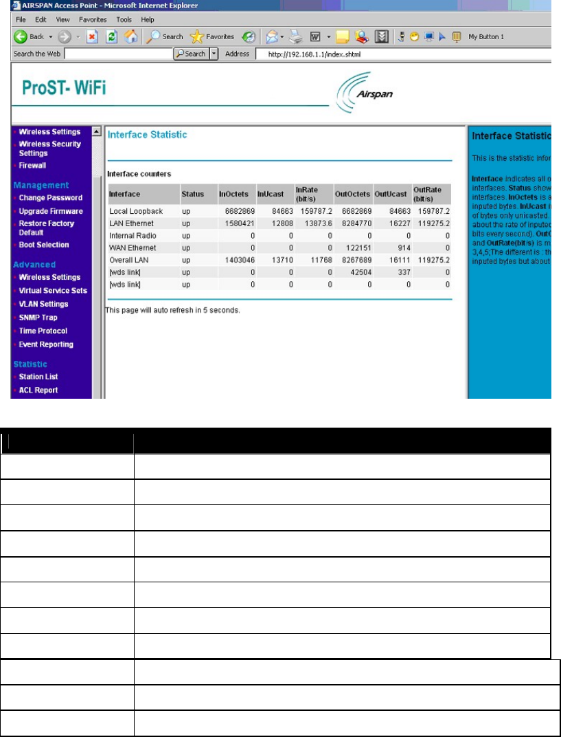
Interface Statistic
Interface Statistic
Interface Indicates all of the system's interfaces
Status Shows the status of all interfaces.
InOctets About the number of inputted bytes.
InUcast Indicates the inputted of bytes only unicasted.
InRate(bit/s) About the rate of inputted bytes (how many bits every second).
OutOctets About the number of outputted bytes.
OutUcast Indicates the outputted of bytes only unicasted.
OutRate(bit/s) About the rate of outputted bytes (how many bits every second).
DHCP Relay Server When “ Enable” DHCP Relay, please provide an IP Address for that DHCP Relay Server.
Apply Means once you change the parameters and save the values
Cancel Means you leave it un-changed

802.11b/g WiFi Module
APPENDIX A: HARDWARE SPECIFICATION
General Specifications Model PROST802.11 Wireless Access Point
Radio Data Rate 1, 2, 5.5, 6, 9, 11, 12, 18, 24, 36, 48 and 54Mbps (Auto Rate Sensing)
Frequency 2.4Ghz to 2.5Ghz CCK and Orthogonal Frequency Division Multiplexing (OFDM)
Encryption WEP , TKIP and AES
Ethernet Interface IEEE 802.3i 10Mbps/ IEEE802.3u 100Mbps
Power 6Vdc @ 2A
Environment Specifications Operating temperature: -40℃~70℃
802.11b/g WiFi Module
Federal Communication Commission Interference Statement
This equipment has been tested and found to comply with the limits for a Class B digital device, pursuant to
Part 15 of the FCC Rules. These limits are designed to provide reasonable protection against harmful
interference in a residential installation. This equipment generates, uses and can radiate radio frequency
energy and, if not installed and used in accordance with the instructions, may cause harmful interference to
radio communications. However, there is no guarantee that interference will not occur in a particular
installation. If this equipment does cause harmful interference to radio or television reception, which can be
determined by turning the equipment off and on, the user is encouraged to try to correct the interference by
one of the following measures:
- Reorient or relocate the receiving antenna.
- Increase the separation between the equipment and receiver.
- Connect the equipment into an outlet on a circuit different from that
to which the receiver is connected.
- Consult the dealer or an experienced radio/TV technician for help.
This device complies with Part 15 of the FCC Rules. Operation is subject to the following two conditions: (1)
This device may not cause harmful interference, and (2) this device must accept any interference received,
including interference that may cause undesired operation.
FCC Caution: Any changes or modifications not expressly approved by the party responsible for compliance
could void the user's authority to operate this equipment.
IMPORTANT NOTE:
FCC Radiation Exposure Statement:
This equipment complies with FCC radiation exposure limits set forth for an uncontrolled environment. This
equipment should be installed and operated with minimum distance 20cm between the radiator & your body.
This transmitter must not be co-located or operating in conjunction with any other antenna or transmitter.
This device is intended only for OEM integrators under the following conditions:
1) The antenna must be installed such that 20 cm is maintained between the antenna and users, and
2) The transmitter module may not be co-located with any other transmitter or antenna.
As long as 2 conditions above are met, further transmitter test will not be required. However, the OEM
integrator is still responsible for testing their end-product for any additional compliance requirements required
with this module installed (for example: wireless AP , wireless Router.).
IMPORTANT NOTE: In the event that these conditions can not be met (for example certain laptop
configurations or co-location with another transmitter), then the FCC authorization is no longer considered
valid and the FCC ID can not be used on the final product. In these circumstances, the OEM integrator will
be responsible for re-evaluating the end product (including the transmitter) and obtaining a separate FCC
authorization.
End Product Labeling
This transmitter module is authorized only for use in device where the antenna may be installed such that 20
cm may be maintained between the antenna and users (for example : wireless AP , wireless Router). The
final end product must be labeled in a visible area with the following: “ Contains TX FCC ID: PD5TYPEIII ” .
Manual Information That Must be Included
The OEM integrator has to be aware not to provide information to the end user regarding how to install or
remove this RF module in the users manual of the end product which integrate this module.
802.11b/g WiFi Module
The users manual for OEM integrators must include the following information in a prominent location
“ IMPORTANT NOTE: To comply with FCC RF exposure compliance requirements, the antenna used for this
transmitter must be installed to provide a separation distance of at least 20 cm from all persons and must not
be co-located or operating in conjunction with any other antenna or transmitter.