Delta Electronics WAP361 Wireless-AC/N Dual Radio Wall Plate Access Point with PoE User Manual wap361 qsg en US
Delta Networks, Inc. Wireless-AC/N Dual Radio Wall Plate Access Point with PoE wap361 qsg en US
Contents
- 1. User Manual (Statement)
- 2. User Manual
- 3. User Manual (statement)
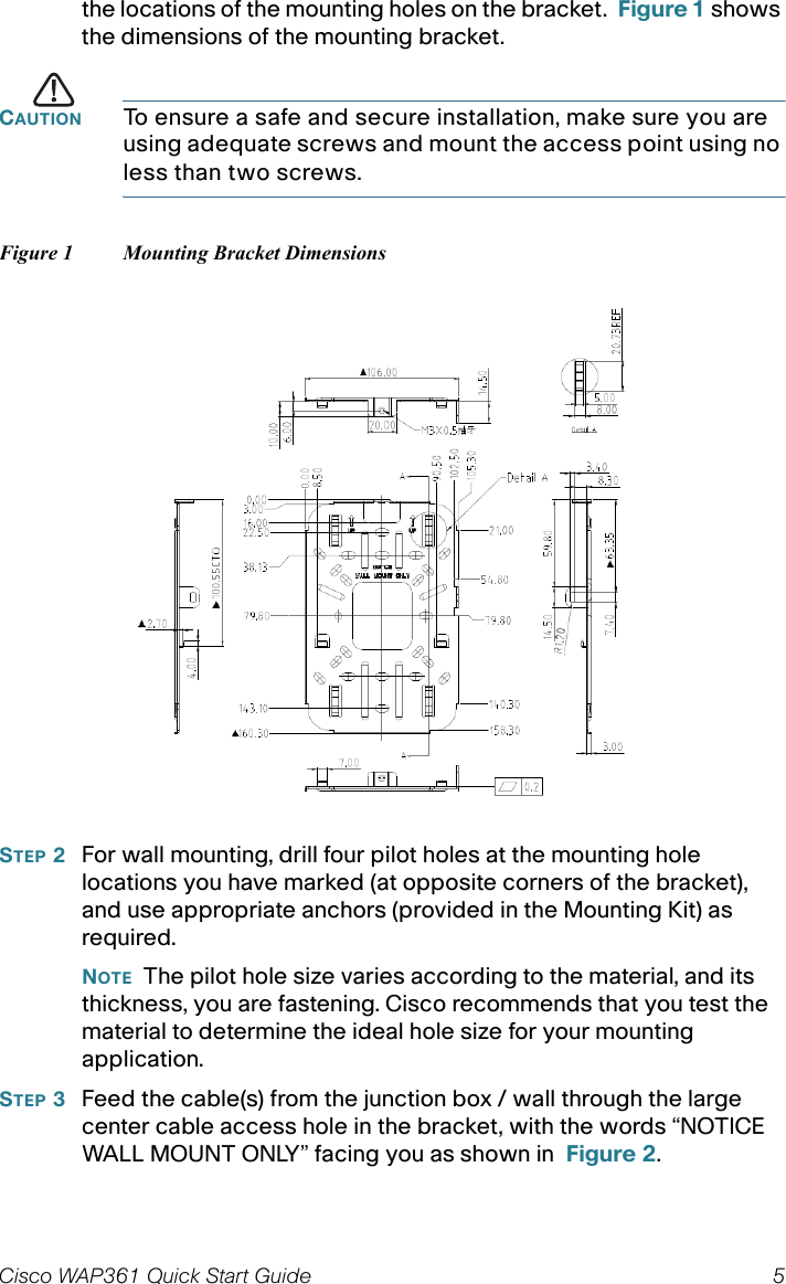
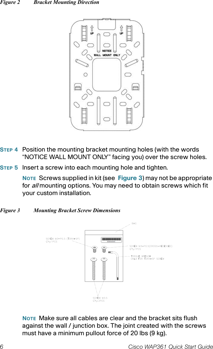
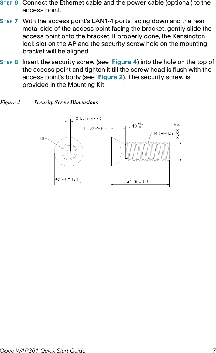
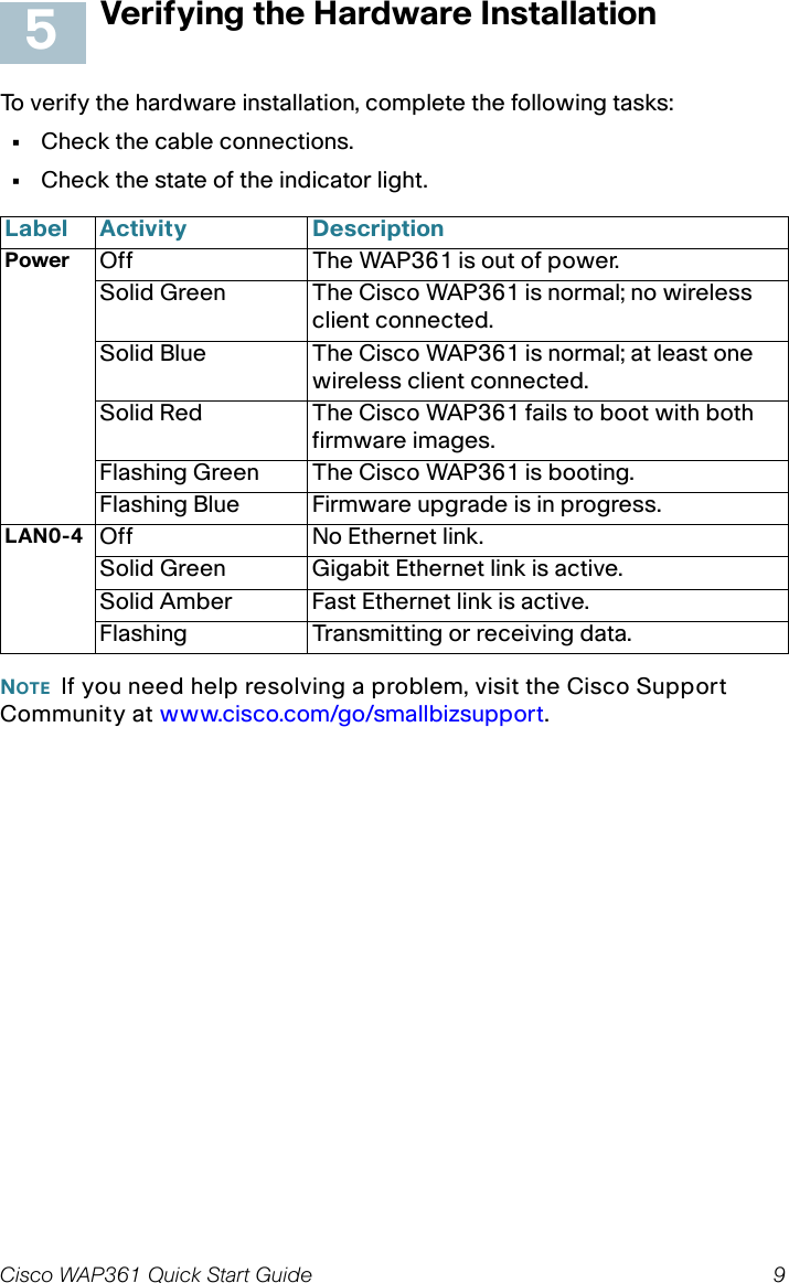
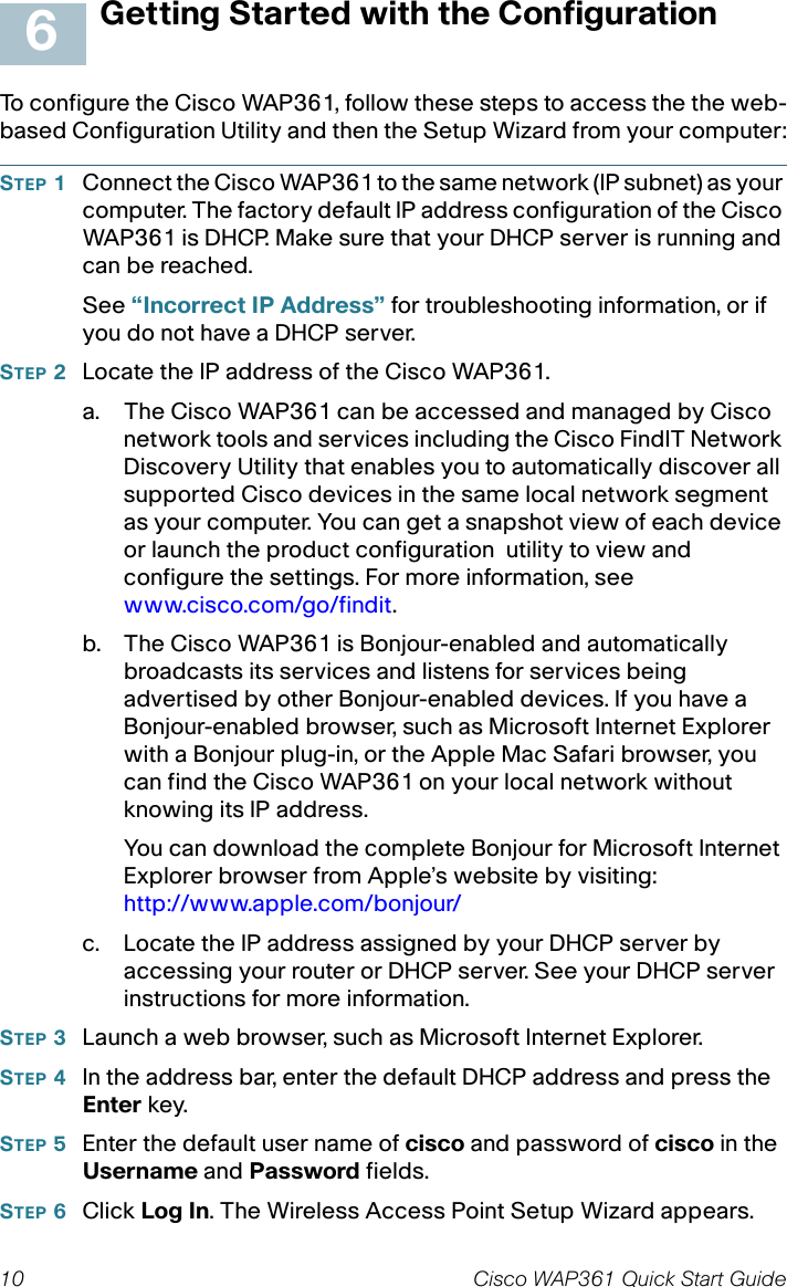
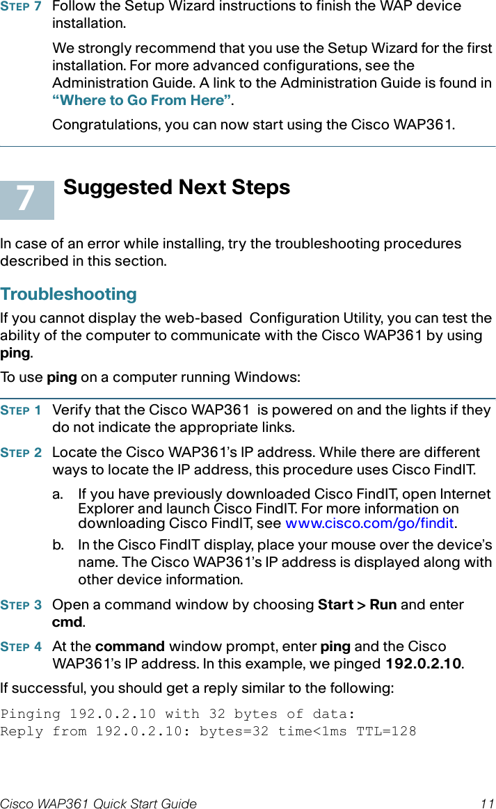
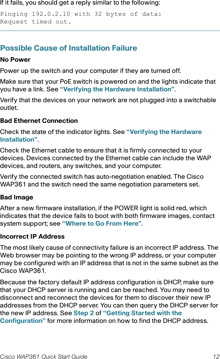
User Manual