Delta Electronics WAP361 Wireless-AC/N Dual Radio Wall Plate Access Point with PoE User Manual wap361 qsg en US
Delta Networks, Inc. Wireless-AC/N Dual Radio Wall Plate Access Point with PoE wap361 qsg en US
Contents
- 1. User Manual (Statement)
- 2. User Manual
- 3. User Manual (statement)
User Manual
Quick Start Guide
Cisco WAP361 Wireless-AC/N Dual Radio Wall
Plate Access Point with PoE

2 Cisco WAP361 Quick Start Guide
Welcome
Thank you for choosing the Cisco WAP361 Wireless-AC/N Dual Radio Wall
Plate Access Point with PoE. The Cisco WAP361 is an indoor concurrent
dual-band radio 802.11ac and 802.11n access point with integrated PoE
switch. -PoE Supplied by UL Listed I.T.E.
This guide provides the general layout of the Cisco WAP361, describe
how to deploy the Cisco WAP361 in your network, and describe how to
configure the Cisco WAP361. For additional information, see
www.cisco.com/go/300_wap_resources.
Package Contents
•Wireless Access Point
•Mounting Kit
•This Quick Start Guide
•Ethernet Cable
•Technical Support Contact
•Pointer Card China RoHS
•EU Directives 1999/5/EC Compliance Information (for EU SKU only)
Before You Begin
Before you begin the installation, make sure that you have the following
equipment and services:
•A computer with browser support for:
– Internet Explorer 7.0 or later
– Chrome 5.0 or later
– Firefox 3.0 or later
– Safari 3.0 or later
•Tools for installing the hardware
•FindIt tool for locating the access point
•One or more Ethernet network switches with PoE
•Mobile devices (iPhone, Android, etc.) via wireless setup SSID.
(Configure via Wi-Fi mobile device with a web browser.)
1

Cisco WAP361 Quick Start Guide 3
Cisco WAP361 Features
Front Panel
The front panel of the Cisco WAP361 consists of one system LED. For full
descriptions of the colors of the lights and their indications, see “Verifying
the Hardware Installation”.
Back Panel
RESET—See “Rebooting the Cisco WAP361 or Resetting to Factory
Defaults” for information on the RESET button.
PD/LAN0—The Powered Device (PD/LAN0) port is used to power the
Cisco WAP361 using PoE.
Right-Side Panel
The right-side panel of the Cisco WAP361 has a Kensington lock slot. You
can use it to attach a cable and lock to the Cisco WAP361.
48V DC—The 48V DC jack is used to connect the power adapter to the
Cisco WAP361 if you are not using PoE.
Top Panel
The top panel of the Cisco WAP361 has the security screw hole.
Bottom Panel
PSE—The Power Sourcing Equipment (PSE) port is used to power the
device that is connected to the Cisco WAP361 through this port.
LAN1-4—The RJ-45 Ethernet port is an auto-sensing, Gigabit Ethernet
(802.3) port used to connect the Cisco WAP361 to network devices, such
as computers, routers, or switches. We strongly recommend that you use a
Category 5e or better cable for gigabit connectivity.
Default Settings
Parameter Default Value
Username cisco
Password cisco
LAN IP Address DHCP address assigned by server
Fallback LAN IP 192.168.1.245
Subnetwork Mask 255.255.255.0
2
4 Cisco WAP361 Quick Start Guide
If you are using a Cisco RV series router, the default range for the DHCP
assigned address is from 192.168.1.100 to 192.168.1.254. Any device
connecting to the same LAN will be assigned an IP address in this range.
Mounting the Cisco WAP361
•We recommend that you mount the Cisco WAP361 to a wall or junction
box.
Placement Tips
• Ambient Temperature—To prevent the Cisco WAP361 from
overheating, do not operate it in an area that exceeds an ambient
temperature of 104°F (40°C).
•Air Flow—Both side panels have vents that must be unobstructed to
prevent overheating.
• Mechanical Loading—The Cisco WAP361 should be level, stable, and
secure to prevent it from sliding or shifting out of position.
Wall Mounting
Cisco WAP361 access points can be mounted on walls and junction
boxes, in the vertical orientation with the security screw on the top and the
LED which is located above the Cisco logo.
STEP 1If you are mounting the AP directly to a junction box, go to Step 3.
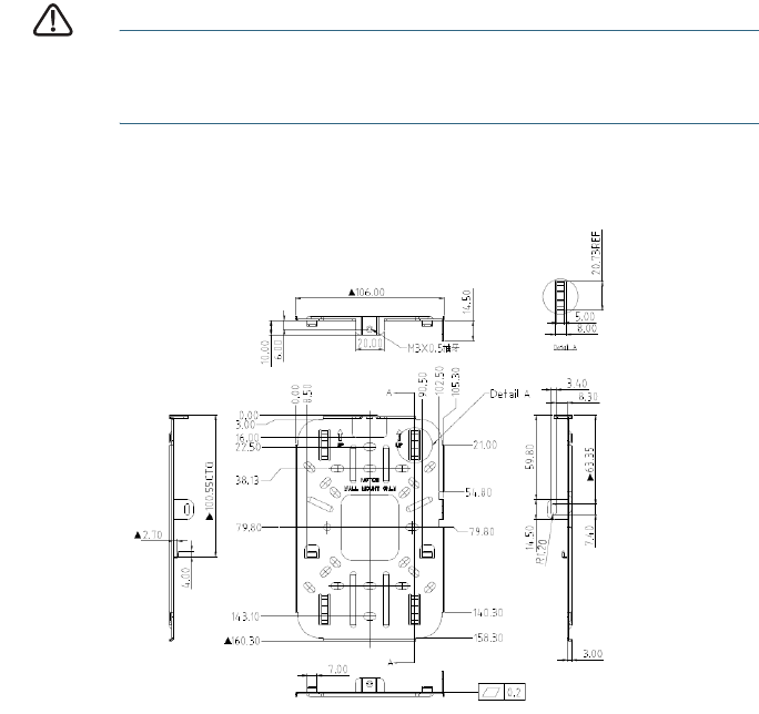
For wall mounting, use the mounting bracket as a template to mark
3
Cisco WAP361 Quick Start Guide 5
the locations of the mounting holes on the bracket. Figure 1 shows
the dimensions of the mounting bracket.
CAUTION To ensure a safe and secure installation, make sure you are
using adequate screws and mount the access point using no
less than two screws.
Figure 1 Mounting Bracket Dimensions
STEP 2For wall mounting, drill four pilot holes at the mounting hole
locations you have marked (at opposite corners of the bracket),
and use appropriate anchors (provided in the Mounting Kit) as
required.
NOTE The pilot hole size varies according to the material, and its
thickness, you are fastening. Cisco recommends that you test the
material to determine the ideal hole size for your mounting
application.
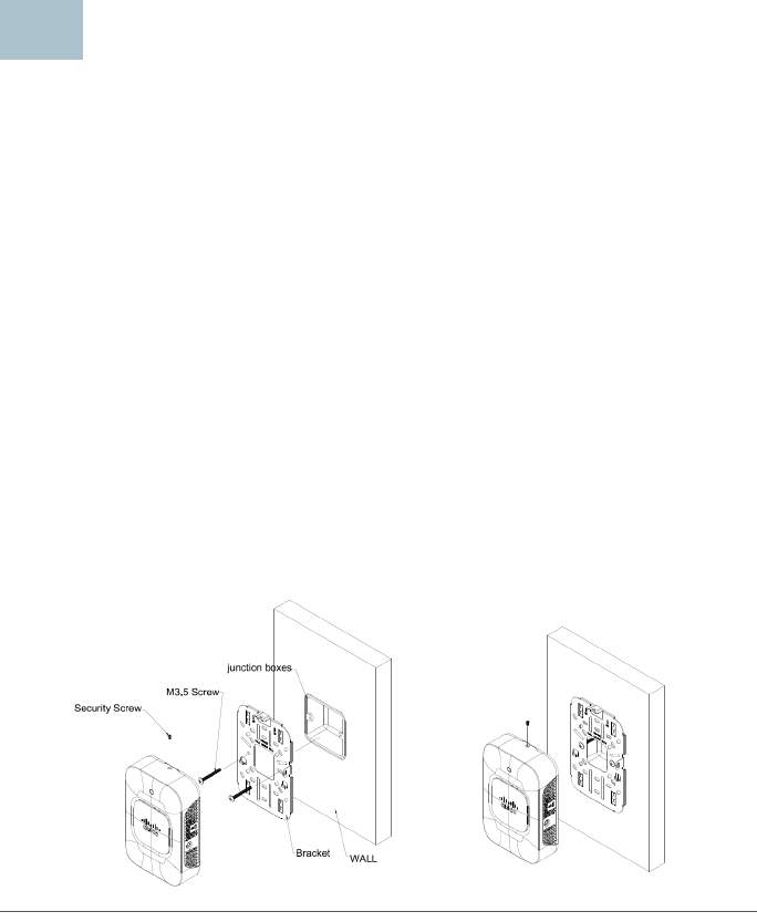
STEP 3Feed the cable(s) from the junction box / wall through the large
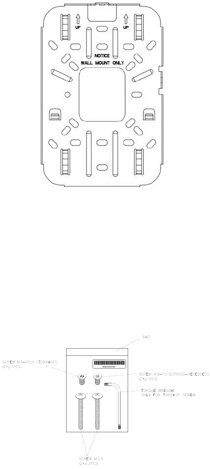
center cable access hole in the bracket, with the words “NOTICE
WALL MOUNT ONLY” facing you as shown in Figure 2.
6 Cisco WAP361 Quick Start Guide
Figure 2 Bracket Mounting Direction
STEP 4Position the mounting bracket mounting holes (with the words
“NOTICE WALL MOUNT ONLY” facing you) over the screw holes.
STEP 5Insert a screw into each mounting hole and tighten.
NOTE Screws supplied in kit (see Figure 3) may not be appropriate
for
all
mounting options. You may need to obtain screws which fit
your custom installation.
Figure 3 Mounting Bracket Screw Dimensions
NOTE Make sure all cables are clear and the bracket sits flush
against the wall / junction box. The joint created with the screws
must have a minimum pullout force of 20 lbs (9 kg).
Cisco WAP361 Quick Start Guide 7
STEP 6Connect the Ethernet cable and the power cable (optional) to the
access point.
STEP 7With the access point’s LAN1-4 ports facing down and the rear
metal side of the access point facing the bracket, gently slide the
access point onto the bracket. If properly done, the Kensington
lock slot on the AP and the security screw hole on the mounting
bracket will be aligned.
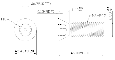
STEP 8Insert the security screw (see Figure 4) into the hole on the top of
the access point and tighten it till the screw head is flush with the
access point's body (see Figure 2). The security screw is
provided in the Mounting Kit.
Figure 4 Security Screw Dimensions

8 Cisco WAP361 Quick Start Guide
Connecting the Cisco WAP361
The default configuration of the Cisco WAP361 has the Wi-Fi radio turned
on. You can perform the initial configuration using either a wired or wireless
connection. This wireless default configuration will not allow traffic
between WiFi and Ethernet; users will need to go through the setup wizard
to resume the traffic between WiFi and Ethernet.
To connect the Cisco WAP361 to the wired network:
STEP 1Connect the Ethernet cable to the Ethernet port of a switch, a router,
or a PC.
STEP 2Connect the other end of the network Ethernet cable to the
Ethernet port of the Cisco WAP361.
STEP 3If PoE is not provided, plug in the supplied power adapter to
provide power to the Cisco WAP361.
To connect the Cisco WAP361 to the network wirelessly:
STEP 1Use wireless clients to locate the WAP361’s SSID (CiscoSB-Setup).
STEP 2Use the ‘cisco123’ passkey to access the access point.
After installation, all lights should be active. Refer to “Verifying the
Hardware Installation” for details about the different lights on the Cisco
WAP361.
NOTE The system provides a one-time-only access to configure the
access point using a wireless connection.
4

Cisco WAP361 Quick Start Guide 9
Verifying the Hardware Installation
To verify the hardware installation, complete the following tasks:
•Check the cable connections.
•Check the state of the indicator light.
NOTE If you need help resolving a problem, visit the Cisco Support
Community at www.cisco.com/go/smallbizsupport.
Label Activity Description
Power Off The WAP361 is out of power.
Solid Green The Cisco WAP361 is normal; no wireless
client connected.
Solid Blue The Cisco WAP361 is normal; at least one
wireless client connected.
Solid Red The Cisco WAP361 fails to boot with both
firmware images.
Flashing Green The Cisco WAP361 is booting.
Flashing Blue Firmware upgrade is in progress.
LAN0-4 Off No Ethernet link.
Solid Green Gigabit Ethernet link is active.
Solid Amber Fast Ethernet link is active.
Flashing Transmitting or receiving data.
5

10 Cisco WAP361 Quick Start Guide
Getting Started with the Configuration
To configure the Cisco WAP361, follow these steps to access the the web-
based Configuration Utility and then the Setup Wizard from your computer:
STEP 1Connect the Cisco WAP361 to the same network (IP subnet) as your
computer. The factory default IP address configuration of the Cisco
WAP361 is DHCP. Make sure that your DHCP server is running and
can be reached.
See “Incorrect IP Address” for troubleshooting information, or if
you do not have a DHCP server.
STEP 2Locate the IP address of the Cisco WAP361.
a. The Cisco WAP361 can be accessed and managed by Cisco
network tools and services including the Cisco FindIT Network
Discovery Utility that enables you to automatically discover all
supported Cisco devices in the same local network segment
as your computer. You can get a snapshot view of each device
or launch the product configuration utility to view and
configure the settings. For more information, see
www.cisco.com/go/findit.
b. The Cisco WAP361 is Bonjour-enabled and automatically
broadcasts its services and listens for services being
advertised by other Bonjour-enabled devices. If you have a
Bonjour-enabled browser, such as Microsoft Internet Explorer
with a Bonjour plug-in, or the Apple Mac Safari browser, you
can find the Cisco WAP361 on your local network without
knowing its IP address.
You can download the complete Bonjour for Microsoft Internet
Explorer browser from Apple’s website by visiting:
http://www.apple.com/bonjour/
c. Locate the IP address assigned by your DHCP server by
accessing your router or DHCP server. See your DHCP server
instructions for more information.
STEP 3Launch a web browser, such as Microsoft Internet Explorer.
STEP 4In the address bar, enter the default DHCP address and press the
Enter key.
STEP 5Enter the default user name of cisco and password of cisco in the
Username and Password fields.
STEP 6Click Log In. The Wireless Access Point Setup Wizard appears.
6

Cisco WAP361 Quick Start Guide 11
STEP 7Follow the Setup Wizard instructions to finish the WAP device
installation.
We strongly recommend that you use the Setup Wizard for the first
installation. For more advanced configurations, see the
Administration Guide. A link to the Administration Guide is found in
“Where to Go From Here”.
Congratulations, you can now start using the Cisco WAP361.
Suggested Next Steps
In case of an error while installing, try the troubleshooting procedures
described in this section.
Troubleshooting
If you cannot display the web-based Configuration Utility, you can test the
ability of the computer to communicate with the Cisco WAP361 by using
ping.
To u s e ping on a computer running Windows:
STEP 1Verify that the Cisco WAP361 is powered on and the lights if they
do not indicate the appropriate links.
STEP 2Locate the Cisco WAP361’s IP address. While there are different
ways to locate the IP address, this procedure uses Cisco FindIT.
a. If you have previously downloaded Cisco FindIT, open Internet
Explorer and launch Cisco FindIT. For more information on
downloading Cisco FindIT, see www.cisco.com/go/findit.
b. In the Cisco FindIT display, place your mouse over the device’s
name. The Cisco WAP361’s IP address is displayed along with
other device information.
STEP 3Open a command window by choosing Start > Run and enter
cmd.
STEP 4At the command window prompt, enter ping and the Cisco
WAP361’s IP address. In this example, we pinged 192.0.2.10.
If successful, you should get a reply similar to the following:
Pinging 192.0.2.10 with 32 bytes of data:
Reply from 192.0.2.10: bytes=32 time<1ms TTL=128
7

Cisco WAP361 Quick Start Guide 12
If it fails, you should get a reply similar to the following:
Pinging 192.0.2.10 with 32 bytes of data:
Request timed out.
Possible Cause of Installation Failure
No Power
Power up the switch and your computer if they are turned off.
Make sure that your PoE switch is powered on and the lights indicate that
you have a link. See “Verifying the Hardware Installation”.
Verify that the devices on your network are not plugged into a switchable
outlet.
Bad Ethernet Connection
Check the state of the indicator lights. See “Verifying the Hardware
Installation”.
Check the Ethernet cable to ensure that it is firmly connected to your
devices. Devices connected by the Ethernet cable can include the WAP
devices, and routers, any switches, and your computer.
Verify the connected switch has auto-negotiation enabled. The Cisco
WAP361 and the switch need the same negotiation parameters set.
Bad Image
After a new firmware installation, if the POWER light is solid red, which
indicates that the device fails to boot with both firmware images, contact
system support; see “Where to Go From Here”.
Incorrect IP Address
The most likely cause of connectivity failure is an incorrect IP address. The
Web browser may be pointing to the wrong IP address, or your computer
may be configured with an IP address that is not in the same subnet as the
Cisco WAP361.
Because the factory default IP address configuration is DHCP, make sure
that your DHCP server is running and can be reached. You may need to
disconnect and reconnect the devices for them to discover their new IP
addresses from the DHCP server. You can then query the DHCP server for
the new IP address. See Step 2 of “Getting Started with the
Configuration” for more information on how to find the DHCP address.

Cisco WAP361 Quick Start Guide 13
If the Cisco WAP361 does not receive a DHCP response (there is no DHCP
server on your network) after 60 seconds, the Cisco WAP361 will fallback
to the following default static IP address: 192.168.1.245 and a default mask
of 255.255.255.0. To reach that IP address, be sure that your computer is
on the 192.168.1.xxx network.
Rebooting the Cisco WAP361 or Resetting
to Factory Defaults
To reboot your Cisco WAP361:
•If the Cisco WAP361 uses a power adapter, with the power on, use the
POWER button to reboot the device. The POWER button only functions
when the Cisco WAP361 uses a power adapter.
•If the power supply is PoE, unplug your Ethernet connection for three
seconds and plug it back in.
•With the power on, press the RESET button with an opened paper clip
for less than 10 seconds, or until the lights go off.
– When all the lights go off, release the RESET button.
– Release the RESET button as soon as the lights go off, or you will
restore the Cisco WAP361 to factory default settings and lose your
configurations.
To reset the Cisco WAP361 to factory default settings:
•With the power on, press and hold the RESET button with an opened
paper clip for more than 10 seconds.
– All of the lights will go off.
– Release the RESET button when the power light turns on.
8

14 Cisco WAP361 Quick Start Guide
Where to Go From Here
For EU lot 26 related test result, please check this web page:
www.cisco.com/go/eu-lot26-results.
Support
Cisco Support
Community
www.cisco.com/go/smallbizsupport
Cisco Support and
Resources
www.cisco.com/go/smallbizhelp
Phone Support Contacts www.cisco.com/en/US/support/
tsd_cisco_small_business
_support_center_contacts.html
Cisco Firmware
Downloads
www.cisco.com/go/smallbizfirmware
Select a link to download firmware for Cisco
products. No login is required.
Cisco Open Source
Requests
www.cisco.com/go/
smallbiz_opensource_request
Cisco Partner Central
(Partner Login Required)
www.cisco.com/web/partners/sell/smb
Product Documentation
Cisco WAP361
Administration Guide
www.cisco.com/go/300_wap_resources
Cisco Power Adapters www.cisco.com/go/wap_accessories
9
Cisco WAP361 Quick Start Guide 15

Americas Headquarters
Cisco Systems, Inc.
www.cisco.com
Cisco has more than 200 offices worldwide.
Addresses, phone numbers, and fax numbers
are listed on the Cisco website at
www.cisco.com/go/offices.
Cisco and the Cisco logo are trademarks or registered trademarks of Cisco and/or its affiliates
in the U.S. and other countries. To view a list of Ciscotrademarks, go to this URL:
www.cisco.com/go/trademarks. Third-party trademarks mentioned are the property of their
respective owners. The use of the word partner does not imply a partnership relationship
between Cisco and any other company. (1110R)
© 2015 Cisco Systems, Inc. All rights reserved.
78-21682-01