Delta Systems 2060500 915 MHz REMOTE CONTROL RECEIVER User Manual USERS MANUAL
Delta Systems INC. 915 MHz REMOTE CONTROL RECEIVER USERS MANUAL
UserManual.wiki
>
Delta Systems
>
2060500 User Manual
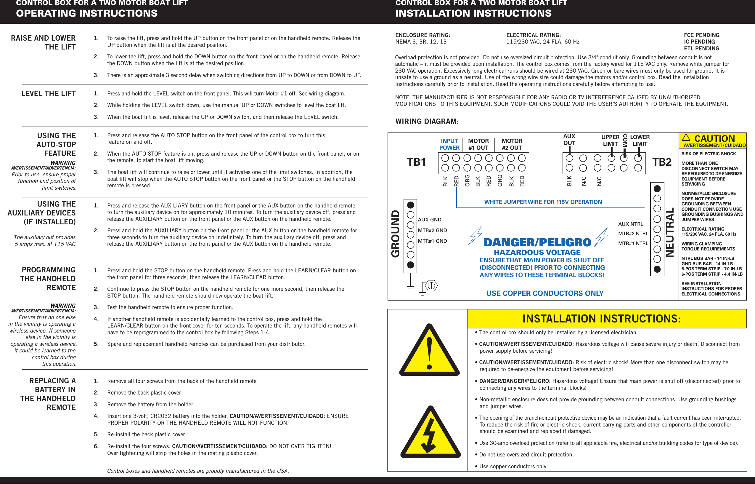
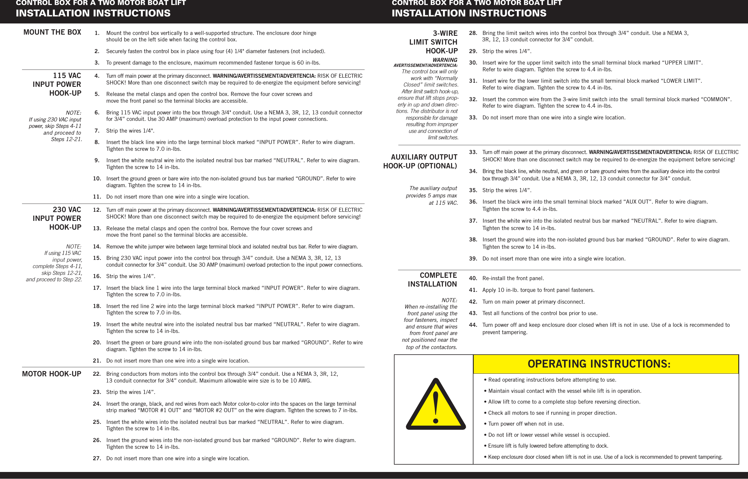
USERS MANUAL
Navigation menu
Upload a User Manual
Namespaces
Wiki Guide
HTML
PDF
Info
Views
User Manual
Discussion / Help
Navigation