Delta Systems 2060500 915 MHz REMOTE CONTROL RECEIVER User Manual USERS MANUAL
Delta Systems INC. 915 MHz REMOTE CONTROL RECEIVER USERS MANUAL
USERS MANUAL
EnclosurE rating: ElEctrical rating: Fcc PEnding
NEMA 3, 3R, 12, 13 115/230 VAC, 24 FLA, 60 Hz ic PEnding
Etl PEnding
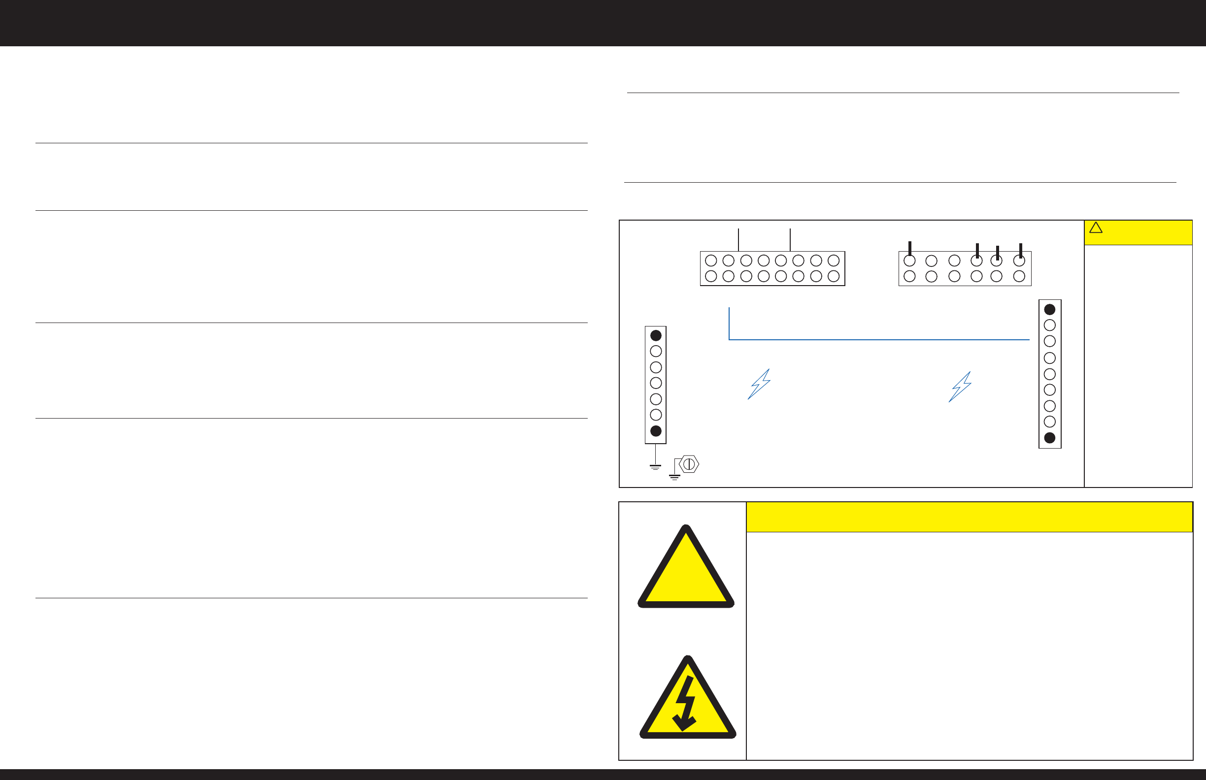
Wiring diagraM:
Overload protection is not provided. Do not use oversized circuit protection. Use 3/4" conduit only. Grounding between conduit is not
automatic – it must be provided upon installation. The control box comes from the factory wired for 115 VAC only. Remove white jumper for
230 VAC operation. Excessively long electrical runs should be wired at 230 VAC. Green or bare wires must only be used for ground. It is
unsafe to use a ground as a neutral. Use of the wrong wire size could damage the motors and/or control box. Read the Installation
Instructions carefully prior to installation. Read the operating instructions carefully before attempting to use.
NOTE: THE MANUFACTURER IS NOT RESPONSIBLE FOR ANY RADIO OR TV INTERFERENCE CAUSED BY UNAUTHORIZED
MODIFICATIONS TO THIS EQUIPMENT. SUCH MODIFICATIONS COULD VOID THE USER’S AUTHORITY TO OPERATE THE EQUIPMENT.
• The control box should only be installed by a licensed electrician.
• caution/aVErtissEMEnt/cuidado: Hazardous voltage will cause severe injury or death. Disconnect from
power supply before servicing!
• caution/aVErtissEMEnt/cuidado: Risk of electric shock! More than one disconnect switch may be
required to de-energize the equipment before servicing!
• dangEr/dangEr/PEligro: Hazardous voltage! Ensure that main power is shut off (disconnected) prior to
connecting any wires to the terminal blocks!
• Non-metallic enclosure does not provide grounding between conduit connections. Use grounding bushings
and jumper wires.
• The opening of the branch-circuit protective device may be an indication that a fault current has been interrupted.
To reduce the risk of fire or electric shock, current-carrying parts and other components of the controller
should be examined and replaced if damaged.
• Use 30-amp overload protection (refer to all applicable re, electrical and/or building codes for type of device).
• Do not use oversized circuit protection.
• Use copper conductors only.
!
installation instructions:
1. To raise the lift, press and hold the UP button on the front panel or on the handheld remote. Release the
UP button when the lift is at the desired position.
2. To lower the lift, press and hold the DOWN button on the front panel or on the handheld remote. Release
the DOWN button when the lift is at the desired position.
3. There is an approximate 3 second delay when switching directions from UP to DOWN or from DOWN to U P.
1. Press and hold the LEVEL switch on the front panel. This will turn Motor #1 off. See wiring diagram.
2. While holding the LEVEL switch down, use the manual UP or DOWN switches to level the boat lift.
3. When the boat lift is level, release the UP or DOWN switch, and then release the LEVEL switch.
1. Press and release the AUTO STOP button on the front panel of the control box to turn this
feature on and off.
2. When the AUTO STOP feature is on, press and release the UP or DOWN button on the front panel, or on
the remote, to start the boat lift moving.
3. The boat lift will continue to raise or lower until it activates one of the limit switches. In addition, the
boat lift will stop when the AUTO STOP button on the front panel or the STOP button on the handheld
remote is pressed.
1. Press and release the AUXILIARY button on the front panel or the AUX button on the handheld remote
to turn the auxiliary device on for approximately 10 minutes. To turn the auxiliary device off, press and
release the AUXILIARY button on the front panel or the AUX button on the handheld remote.
2. Press and hold the AUXILIARY button on the front panel or the AUX button on the handheld remote for
three seconds to turn the auxiliary device on indefinitely. To turn the auxiliary device off, press and
release the AUXILIARY button on the front panel or the AUX button on the handheld remote.
1. Press and hold the STOP button on the handheld remote. Press and hold the LEARN/CLEAR button on
the front panel for three seconds, then release the LEARN/CLEAR button.
2. Continue to press the STOP button on the handheld remote for one more second, then release the
STOP button. The handheld remote should now operate the boat lift.
3. Test the handheld remote to ensure proper function.
4. If another handheld remote is accidentally learned to the control box, press and hold the
LEARN/CLEAR button on the front cover for ten seconds. To operate the lift, any handheld remotes will
have to be reprogrammed to the control box by following Steps 1-4.
5. Spare and replacement handheld remotes can be purchased from your distributor.
1. Remove all four screws from the back of the handheld remote
2. Remove the back plastic cover
3. Remove the battery from the holder
4. Insert one 3-volt, CR2032 battery into the holder. caution/aVErtissEMEnt/cuidado: ENSURE
PROPER POLARITY OR THE HANDHELD REMOTE WILL NOT FUNCTION.
5. Re-install the back plastic cover
6. Re-install the four screws. caution/aVErtissEMEnt/cuidado: DO NOT OVER TIGHTEN!
Over tightening will strip the holes in the mating plastic cover.
raisE and loWEr
thE liFt
lEVEl thE liFt
using thE
auto-stoP
FEaturE
WARNING
AVERTISSEMENT/ADVERTENCIA:
Prior to use, ensure proper
function and position of
limit switches.
rEPlacing a
battEry in
thE handhEld
rEMotE
using thE
auxiliary dEVicEs
(iF installEd)
The auxiliary out provides
5 amps max. at 115 VAC.
PrograMMing
thE handhEld
rEMotE
WARNING
AVERTISSEMENT/ADVERTENCIA:
Ensure that no one else
in the vicinity is operating a
wireless device. If someone
else in the vicinity is
operating a wireless device,
it could be learned to the
control box during
this operation.
CONTROL BOX FOR A TWO MOTOR BOAT LIFT
INSTALLATION INSTRUCTIONS
CONTROL BOX FOR A TWO MOTOR BOAT LIFT
OPERATING INSTRUCTIONS
Control boxes and handheld remotes are proudly manufactured in the USA.
N/C
N/C
GROUND
NEUTRAL
INPUT
POWER
WHITE JUMPER WIRE FOR 115V OPERATION
USE COPPER CONDUCTORS ONLY
DANGER/PELIGRO
HAZARDOUS VOLTAGE
ENSURE THAT MAIN POWER IS SHUT OFF
(DISCONNECTED) PRIOR TO CONNECTING
ANY WIRES TO THESE TERMINAL BLOCKS!
MOTOR
#1 OUT
AUX
OUT
UPPER
LIMIT
LOWER
LIMIT
RISK OF ELECTRIC SHOCK
MORE THAN ONE
DISCONNECT SWITCH MAY
BE REQUIRED TO DE-ENERGIZE
EQUIPMENT BEFORE
SERVICING
NONMETALLIC ENCLOSURE
DOES NOT PROVIDE
GROUNDING BETWEEN
CONDUIT CONNECTION USE
GROUNDING BUSHINGS AND
JUMPER WIRES
ELECTRICAL RATING:
115/230 VAC, 24 FLA, 60 Hz
WIRING CLAMPING
TORQUE REQUIREMENTS
NTRL BUS BAR - 14 IN-LB
GND BUS BAR - 14 IN-LB
8-POS TERM STRIP - 7.0 IN-LB
6-POS TERM STRIP - 4.4 IN-LB
SEE INSTALLATION
INSTRUCTIONS FOR PROPER
ELECTRICAL CONNECTIONS
MOTOR
#2 OUT
AUX GND
AUX NTRL
MTR#2 NTRL
MTR#1 NTRL
BLK
BLK
RED
N/C
ORG
ORG
RED
RED
BLK
BLK
MTR#2 GND
MTR#1 GND
CAUTION
AVERTISSEMENT/CUIDADO
!
N/C
COM
TB1 TB2
CONTROL BOX FOR A TWO MOTOR BOAT LIFT
INSTALLATION INSTRUCTIONS
CONTROL BOX FOR A TWO MOTOR BOAT LIFT
INSTALLATION INSTRUCTIONS
1. Mount the control box vertically to a well-supported structure. The enclosure door hinge
should be on the left side when facing the control box.
2. Securely fasten the control box in place using four (4) 1/4" diameter fasteners (not included).
3. To prevent damage to the enclosure, maximum recommended fastener torque is 60 in-lbs.
4. Turn off main power at the primary disconnect. Warning/aVErtissEMEnt/adVErtEncia: RISK OF ELECTRIC
SHOCK! More than one disconnect switch may be required to de-energize the equipment before servicing!
5. Release the metal clasps and open the control box. Remove the four cover screws and
move the front panel so the terminal blocks are accessible.
6. Bring 115 VAC input power into the box through 3/4" conduit. Use a NEMA 3, 3R, 12, 13 conduit connector
for 3/4” conduit. Use 30 AMP (maximum) overload protection to the input power connections.
7. Strip the wires 1/4".
8. Insert the black line wire into the large terminal block marked “INPUT POWER”. Refer to wire diagram.
Tighten the screw to 7.0 in-lbs.
9. Insert the white neutral wire into the isolated neutral bus bar marked “NEUTRAL”. Refer to wire diagram.
Tighten the screw to 14 in-lbs.
10. Insert the ground green or bare wire into the non-isolated ground bus bar marked “GROUND”. Refer to wire
diagram. Tighten the screw to 14 in-lbs.
11. Do not insert more than one wire into a single wire location.
12. Turn off main power at the primary disconnect. Warning/aVErtissEMEnt/adVErtEncia: RISK OF ELECTRIC
SHOCK! More than one disconnect switch may be required to de-energize the equipment before servicing!
13. Release the metal clasps and open the control box. Remove the four cover screws and
move the front panel so the terminal blocks are accessible.
14. Remove the white jumper wire between large terminal block and isolated neutral bus bar. Refer to wire diagram.
15. Bring 230 VAC input power into the control box through 3/4” conduit. Use a NEMA 3, 3R, 12, 13
conduit connector for 3/4” conduit. Use 30 AMP (maximum) overload protection to the input power connections.
16. Strip the wires 1/4”.
17. Insert the black line 1 wire into the large terminal block marked “INPUT POWER”. Refer to wire diagram.
Tighten the screw to 7.0 in-lbs.
18. Insert the red line 2 wire into the large terminal block marked “INPUT POWER”. Refer to wire diagram.
Tighten the screw to 7.0 in-lbs.
19. Insert the white neutral wire into the isolated neutral bus bar marked “NEUTRAL”. Refer to wire diagram.
Tighten the screw to 14 in-lbs.
20. Insert the green or bare ground wire into the non-isolated ground bus bar marked “GROUND”. Refer to wire
diagram. Tighten the screw to 14 in-lbs.
21. Do not insert more than one wire into a single wire location.
22. Bring conductors from motors into the control box through 3/4” conduit. Use a NEMA 3, 3R, 12,
13 conduit connector for 3/4” conduit. Maximum allowable wire size is to be 10 AWG.
23. Strip the wires 1/4”.
24. Insert the orange, black, and red wires from each Motor color-to-color into the spaces on the large terminal
strip marked “MOTOR #1 OUT” and “MOTOR #2 OUT” on the wire diagram. Tighten the screws to 7 in-lbs.
25. Insert the white wires into the isolated neutral bus bar marked “NEUTRAL”. Refer to wire diagram.
Tighten the screw to 14 in-lbs.
26. Insert the ground wires into the non-isolated ground bus bar marked “GROUND”. Refer to wire diagram.
Tighten the screw to 14 in-lbs.
27. Do not insert more than one wire into a single wire location.
28. Bring the limit switch wires into the control box through 3/4” conduit. Use a NEMA 3,
3R, 12, 13 conduit connector for 3/4” conduit.
29. Strip the wires 1/4”.
30. Insert wire for the upper limit switch into the small terminal block marked “UPPER LIMIT”.
Refer to wire diagram. Tighten the screw to 4.4 in-lbs.
31. Insert wire for the lower limit switch into the small terminal block marked “LOWER LIMIT”.
Refer to wire diagram. Tighten the screw to 4.4 in-lbs.
32. Insert the common wire from the 3-wire limit switch into the small terminal block marked “COMMON”.
Refer to wire diagram. Tighten the screw to 4.4 in-lbs.
33. Do not insert more than one wire into a single wire location.
33. Turn off main power at the primary disconnect. Warning/aVErtissEMEnt/adVErtEncia: RISK OF ELECTRIC
SHOCK! More than one disconnect switch may be required to de-energize the equipment before servicing!
34. Bring the black line, white neutral, and green or bare ground wires from the auxiliary device into the control
box through 3/4” conduit. Use a NEMA 3, 3R, 12, 13 conduit connector for 3/4” conduit.
35. Strip the wires 1/4”.
36. Insert the black wire into the small terminal block marked “AUX OUT”. Refer to wire diagram.
Tighten the screw to 4.4 in-lbs.
37. Insert the white wire into the isolated neutral bus bar marked “NEUTRAL”. Refer to wire diagram.
Tighten the screw to 14 in-lbs.
38. Insert the ground wire into the non-isolated ground bus bar marked “GROUND”. Refer to wire diagram.
Tighten the screw to 14 in-lbs.
39. Do not insert more than one wire into a single wire location.
40. Re-install the front panel.
41. Apply 10 in-lb. torque to front panel fasteners.
42. Turn on main power at primary disconnect.
43. Test all functions of the control box prior to use.
44. Turn power off and keep enclosure door closed when lift is not in use. Use of a lock is recommended to
prevent tampering.
Mount thE box
115 Vac
inPut PoWEr
hook-uP
NOTE:
If using 230 VAC input
power, skip Steps 4-11
and proceed to
Steps 12-21.
230 Vac
inPut PoWEr
hook-uP
NOTE:
If using 115 VAC
input power,
complete Steps 4-11,
skip Steps 12-21,
and proceed to Step 22.
Motor hook-uP
3-WirE
liMit sWitch
hook-uP
WARNING
AVERTISSEMENT/ADVERTENCIA:
The control box will only
work with “Normally
Closed” limit switches.
After limit switch hook-up,
ensure that lift stops prop-
erly in up and down direc-
tions. The distributor is not
responsible for damage
resulting from improper
use and connection of
limit switches.
auxiliary outPut
hook-uP (oPtional)
The auxiliary output
provides 5 amps max
at 115 VAC.
coMPlEtE
installation
NOTE:
When re-installing the
front panel using the
four fasteners, inspect
and ensure that wires
from front panel are
not positioned near the
top of the contactors.
• Read operating instructions before attempting to use.
• Maintain visual contact with the vessel while lift is in operation.
• Allow lift to come to a complete stop before reversing direction.
• Check all motors to see if running in proper direction.
• Turn power off when not in use.
• Do not lift or lower vessel while vessel is occupied.
• Ensure lift is fully lowered before attempting to dock.
• Keep enclosure door closed when lift is not in use. Use of a lock is recommended to prevent tampering.
!
oPErating instructions: