Delta Tau Acc 24M2A Users Manual
2015-07-14
: Delta-Tau Delta-Tau-Acc-24M2A-Users-Manual-773928 delta-tau-acc-24m2a-users-manual-773928 delta-tau pdf
Open the PDF directly: View PDF ![]() .
.
Page Count: 101 [warning: Documents this large are best viewed by clicking the View PDF Link!]
- Introduction
- Specifications
- Receiving and Unpacking
- Mounting
- Connector Pinouts
- J10: 24 VDC Logic Power Input
- J1: Amplifier Channel 1
- J2: Amplifier Channel 2
- J6: Flags and Limits
- J11 & J12: Encoder Feedback, Digital A Quad B
- J11 & J12: Encoder Feedback, SSI
- J11 & J12: Encoder Feedback, Sinusoidal
- J11 & J12: Encoder Feedback, EnDat
- J11 & J12: Encoder Feedback, HiperFace
- J11 & J12: Encoder Feedback, Resolver
- Universal Serial Bus Port (USB Port)
- MACRO Fiber Connector
- MACRO RJ-45 Copper Connector
- Sample Wiring Diagrams
- Troubleshooting
- Configuring with Turbo PMAC
- Quick Review: Nodes and Addressing
- Setup Overview
- Setup Step 1: MACRO Connectivity
- Setup Step 2: Communicating with ACC-24M2A over MACRO ASCII
- Setup Step 3: Motor Setup
- Configuring with Power PMAC
- Quick Review: Nodes and Addressing
- Setup Overview
- Setup Step 1: MACRO Connectivity
- Setup Step 2: Communicating with ACC-24M2A over MACRO ASCII
- Setup Step 3: Motor Setup
- layout
- appendix A: Jumpers
- Appendix B: Schematics
- Appendix C: Sinusoidal Interpolation

Single Source Machine Control ……………………………………………..…...………………. Power // Flexibility // Ease of Use
21314 Lassen St. Chatsworth, CA 91311 // Tel. (818) 998-2095 Fax. (818) 998-7807 // www.deltatau.com
^1 USER MANUAL
^2 Accessory 24M2A
^3 MACRO Analog Output Servo Module
^4 3Ax-603744-10x
^5 February 14, 2015
DELTA TAU
Data Systems, Inc.
NEW IDEAS IN MOTION …

Accessory 24M2A
Copyright Information
© 2/14/2015 Delta Tau Data Systems, Inc. All rights reserved.
This document is furnished for the customers of Delta Tau Data Systems, Inc. Other uses are
unauthorized without written permission of Delta Tau Data Systems, Inc. Information contained in this
manual may be updated from time-to-time due to product improvements, etc., and may not conform in
every respect to former issues.
To report errors or inconsistencies, call or email:
Delta Tau Data Systems, Inc. Technical Support
Phone: (818) 717-5656
Fax: (818) 998-7807
Email: support@deltatau.com
Website: http://www.deltatau.com
Operating Conditions
All Delta Tau Data Systems, Inc. motion controller products, accessories, and amplifiers contain static
sensitive components that can be damaged by incorrect handling. When installing or handling Delta Tau
Data Systems, Inc. products, avoid contact with highly insulated materials. Only qualified personnel
should be allowed to handle this equipment.
In the case of industrial applications, we expect our products to be protected from hazardous or
conductive materials and/or environments that could cause harm to the controller by damaging
components or causing electrical shorts. When our products are used in an industrial environment, install
them into an industrial electrical cabinet or industrial PC to protect them from excessive or corrosive
moisture, abnormal ambient temperatures, and conductive materials. If Delta Tau Data Systems, Inc.
products are directly exposed to hazardous or conductive materials and/or environments, we cannot
guarantee their operation.
Accessory 24M2A
Safety Instructions
Qualified personnel must transport, assemble, install, and maintain this equipment. Properly qualified
personnel are persons who are familiar with the transport, assembly, installation, and operation of
equipment. The qualified personnel must know and observe the following standards and regulations:
IEC364resp.CENELEC HD 384 or DIN VDE 0100
IEC report 664 or DIN VDE 0110
National regulations for safety and accident prevention or VBG 4
Incorrect handling of products can result in injury and damage to persons and machinery. Strictly adhere
to the installation instructions. Electrical safety is provided through a low-resistance earth connection. It
is vital to ensure that all system components are connected to earth ground.
This product contains components that are sensitive to static electricity and can be damaged by incorrect
handling. Avoid contact with high insulating materials (artificial fabrics, plastic film, etc.). Place the
product on a conductive surface. Discharge any possible static electricity build-up by touching an
unpainted, metal, grounded surface before touching the equipment.
Keep all covers and cabinet doors shut during operation. Be aware that during operation, the product has
electrically charged components and hot surfaces. Control and power cables can carry a high voltage,
even when the motor is not rotating. Never disconnect or connect the product while the power source is
energized to avoid electric arcing.
A Warning identifies hazards that could result in personal injury or
death. It precedes the discussion of interest.
Warning
Caution
A Caution identifies hazards that could result in equipment damage. It
precedes the discussion of interest.
Note
A Note identifies information critical to the understanding or use of
the equipment. It follows the discussion of interest.

Accessory 24M2A
REVISION HISTORY
REV.
DESCRIPTION
DATE
CHG
APPVD
1
CHANGED 7-SEGMENT DISPLAY DESCRIPTIONS
REMOVED DUPLICATE SECTIONS FOR 7-SEGMENT
DISPLAY AND CONNECTOR DESCRIPTIONS
FORMATTING HEADER/FOOTER CORRECTIONS
MOVED “FLAG AND LIMIT WIRING” TO
“CONNECTIONS” SECTION
06/11/06
C.PERRY
A. SOTELO
2
E-POINT JUMPER DESCRIPTIONS REVISED
06/19/06
C.PERRY
A. SOTELO
3
REVISED MACRO FIBER OPTION CONNECTOR
DESCRIPTIONS
CHANGED MECHANICAL LAYOUT AND
CONNECTION SCHEMATICS
CHANGED 24v INPUT LOGIC SUPPLY CONNECTOR
(j10) WIRING
ADDED TWO SINGLE-ENDED WIRING METHODS
FOR SINUSIOD FEEDBACK
MODIFIED MACRO RING ASCII COMMANDS
MACRO ASCII COMMUNICATION GLOBAL
COMMANDS
REVISED “SETTING UP DIGITAL QUADRATURE
ENCODERS”
REVISED “SET UP PROCEDURES FOR SSI
ENCODERS”
REVISED “SET UP PROCEDURES FOR RESOLVERS”
REVISED “SET UP PROCEDURES FOR SINUSOIDAL
ENCODERS”
REVISED “SET UP PROCEDURES FOR PHASE
SHIFT”
REVISED “SET UP PROCEDURES FOR POWER-ON
ABSOLUTE POSITION OF RESOLVER
ADDED “MANUAL SETUP FOR MOTOR OPERATION”
SECTION
08/21/08
C.PERRY
K. ZHAO
4
ADDED MI16, MI17 AND MI18 FUNCTIONALITY
DESCRIPTION
01/05/10
C.PERRY
S.SATTARI
5
COMPLETE MANUAL REVISION
02/14/15
DCDP
R. NADDAF


Accessory 24M2A
Introduction 7
Table of Contents
INTRODUCTION .....................................................................................................................9
SPECIFICATIONS ................................................................................................................. 10
Part Number .............................................................................................................................. 10
ACC-24M2A Options ............................................................................................................... 10
Environmental Specifications .................................................................................................... 11
Electrical Specifications ............................................................................................................ 11
Physical Specifications .............................................................................................................. 11
RECEIVING AND UNPACKING ......................................................................................... 12
Unpacking Guidelines ............................................................................................................... 12
Use of Equipment ..................................................................................................................... 12
MOUNTING ........................................................................................................................... 13
Installation Guidelines............................................................................................................... 13
Connector Locations ................................................................................................................. 14
CONNECTOR PINOUTS ...................................................................................................... 15
J10: 24 VDC Logic Power Input ................................................................................................. 15
J1: Amplifier Channel 1 ............................................................................................................ 16
J2: Amplifier Channel 2 ............................................................................................................ 16
J6: Flags and Limits .................................................................................................................. 17
J11 & J12: Encoder Feedback, Digital A Quad B ...................................................................... 18
J11 & J12: Encoder Feedback, SSI ............................................................................................ 19
J11 & J12: Encoder Feedback, Sinusoidal ................................................................................. 20
J11 & J12: Encoder Feedback, EnDat ........................................................................................ 21
J11 & J12: Encoder Feedback, HiperFace ................................................................................. 22
J11 & J12: Encoder Feedback, Resolver .................................................................................... 23
Universal Serial Bus Port (USB Port) ........................................................................................ 24
MACRO Fiber Connector ......................................................................................................... 25
MACRO RJ-45 Copper Connector ............................................................................................ 25
Sample Wiring Diagrams .......................................................................................................... 26
J6: Flags .......................................................................................................................................... 26
J11 & J12: Encoder Feedback, Digital A Quad B ............................................................................. 28
J11 & J12: Encoder Feedback, SSI ................................................................................................... 28
J11 & J12: Encoder Feedback, Sinusoidal ........................................................................................ 29
J11 & J12: Encoder Feedback, EnDat .............................................................................................. 32
J11 & J12: Encoder Feedback, HiperFace ....................................................................................... 32
J11 & J12: Encoder Feedback, Resolver .......................................................................................... 33
TROUBLESHOOTING .......................................................................................................... 34

Accessory 24M2A
Introduction 8
Status LED Indicators ............................................................................................................... 34
7-Segment LED Indicator.......................................................................................................... 34
CONFIGURING WITH TURBO PMAC .............................................................................. 35
Quick Review: Nodes and Addressing....................................................................................... 35
Setup Overview ......................................................................................................................... 37
Setup Step 1: MACRO Connectivity ......................................................................................... 38
Setup Step 2: Communicating with ACC-24M2A over MACRO ASCII ................................... 39
Setup Step 3: Motor Setup ......................................................................................................... 40
Clocks .............................................................................................................................................. 40
Activating Motors and Disabling Commutation ................................................................................ 40
Motor Feedback ............................................................................................................................... 41
Flags ................................................................................................................................................ 49
Output Commands ............................................................................................................................ 49
I2T Settings ...................................................................................................................................... 50
DAC Calibration .............................................................................................................................. 51
Open Loop Test ................................................................................................................................ 52
Servo Loop Tuning ........................................................................................................................... 53
CONFIGURING WITH POWER PMAC ............................................................................. 58
Quick Review: Nodes and Addressing....................................................................................... 58
Setup Overview ......................................................................................................................... 62
Setup Step 1: MACRO Connectivity ......................................................................................... 63
Setup Step 2: Communicating with ACC-24M2A over MACRO ASCII ................................... 64
Setup Step 3: Motor Setup ......................................................................................................... 65
Clocks .............................................................................................................................................. 65
Activating Motors and Disabling Commutation ................................................................................ 67
Motor Feedback ............................................................................................................................... 68
Flags ................................................................................................................................................ 77
Output Commands ............................................................................................................................ 78
I2T Settings ....................................................................................................................................... 79
DAC Calibration .............................................................................................................................. 79
Open Loop Test ................................................................................................................................ 81
Servo Loop Tuning ........................................................................................................................... 83
LAYOUT ................................................................................................................................. 88
APPENDIX A: JUMPERS ..................................................................................................... 89
APPENDIX B: SCHEMATICS .............................................................................................. 90
APPENDIX C: SINUSOIDAL INTERPOLATION ............................................................ 101

Accessory 24M2A
Introduction 9
INTRODUCTION
The ACC-24M2A is a two (2) axis servo peripheral designed to work with
Turbo PMAC2 Ultralite, Power PMAC EtherLite, or UMAC MACRO
controllers to remotely interface to two (2) channels of analog style amplifiers.
This device produces a ± 10 Vdc control signal to control analog amplifiers.
The ACC-24M2A can process the following feedback types:
Quadrature
1 Vpp Sinusoidal
Resolver
SSI

Accessory 24M2A
Specifications 10
SPECIFICATIONS
Part Number
4 - 3 7 4 4 - 0 0 - 0 0 - 0 00
ACC-24M2A
MACRO Communication Options
* If Any Additional Option is required, contact factory for digits K and L (Factory Assigned digits).
G
0 - Standard Quadrature Encoder Feedback
3 - Quadrature Encoder Feedback and
Two channels of sinusoidal, Resolver,
Two channels of SSI Encoder Feedback
MACRO Node Options
G
A - Fiber-Optic MACRO Transceiver
C - RJ-45 MACRO Connector
D
K L
H
00 - No Additional* Options
xx - Factory assigned digits
for Additional* Options
K L
Factory Assigned Options
D
ACC-24M2A Options
ACC-24M2A may be ordered equipped with the following options:
Options Included
Part Number
2-axis MACRO Analog Servo Peripheral With
Fiber-optic MACRO connectors (Opt-A Included)
4-3744-00-A000-00000
2-axis MACRO Analog Servo Peripheral With
RJ-45 isolated electrical MACRO connectors (Opt-C Included)
4-3744-00-C000-00000
2-axis MACRO Analog Servo Peripheral With
Fiber-optic MACRO connectors (Opt-A Included)
Two channels of sinusoidal, Resolver (Opt-3 Included)
Two channels of SSI Encoder Feedback
4-3744-00-A003-00000
2-axis MACRO Analog Servo Peripheral With
RJ-45 isolated electrical MACRO connectors (Opt-C Included)
Two channels of sinusoidal, Resolver (Opt-3 Included)
Two channels of SSI Encoder Feedback
4-3744-00-C003-00000
Accessory 24M2A
Specifications 11
Environmental Specifications
Description
Unit
Specifications
Operating Temperature
°C
+0 to 45°C
Rated Storage Temperature
°C
-25 to +70
Humidity
%
10% to 90% non-condensing
Shock
Call Factory
Vibration
Call Factory
Operating Altitude
Feet (Meters)
To 3300 feet (1000meters)
Air Flow Clearances
in (mm)
1" (2.54mm) above and below unit for air flow
Electrical Specifications
Main Input Power
Nominal Input Voltage (Vdc)
24 Vdc
Output Power
DAC Output (Vdc)
+/- 10 Vdc
DAC Output (A)
0.045A
Flag Output (Vdc)
12-24Vdc Standard, 5 Vdc w/ RP38 Installed
Flag Input (Vdc)
12-24Vdc Standard, 5 Vdc w/ RP38 Installed
Note
Installing a 1 K resistor pack at RP38 will make the flags 5 Vdc.
Physical Specifications
Width
Height
Depth
Overall Dimensions
2.00in./50.8mm
9.75in./ 247.7mm
6.50in./ 165.1mm
Mounting Dimensions
1.25in./31.75mm
9.375in./ 238.13mm
Weight: 2.3 lbs / 1.0 kg

Accessory 24M2A
Receiving and Unpacking 12
RECEIVING AND UNPACKING
Unpacking Guidelines
Delta Tau products are thoroughly tested at the factory and carefully packaged for shipment. When the
ACC-24M2A is received, do the following immediately:
1. Inspect the condition of the shipping container and report any damage immediately to the commercial
carrier that delivered the drive.
2. Remove the device from the shipping container and remove all packing materials. Check all shipping
material for connector kits, documentation, diskettes, CD ROM, or other small pieces of equipment.
Be aware that some connector kits and other equipment pieces may be quite small and can be
discarded accidentally if care is not used when unpacking the equipment. The container and packing
materials can be retained for future shipment.
3. Electronic components in this device are design-hardened to reduce static sensitivity. However, use
proper procedures when handling the equipment.
4. If ACC-24M2A is to be stored for several weeks before use, be sure that it is stored in a location that
conforms to published storage humidity and temperature specifications stated in this manual.
Use of Equipment
The following guidelines describe the restrictions for proper use of ACC-24M2A:
The components built into electrical equipment or machines can be used only as integral components
of such equipment.
ACC-24M2A must not be operated on power supply networks without a ground or with an
asymmetrical ground.
ACC-24M2A may be operated only in a closed switchgear cabinet, taking into account the ambient
conditions defined in the environmental specifications.
Delta Tau guarantees the conformance of ACC-24M2A with the standards for industrial areas stated in
this manual only if Delta Tau components (cables, controllers, etc.) are used.

Accessory 24M2A
Mounting 13
MOUNTING
Installation Guidelines
This product should be installed in an area that is protected from direct sunlight, corrosives, harmful gases
or liquids, dust, metallic particles, and other contaminants. Exposure to these can reduce the operating
life and degrade the performance.
A couple other factors to evaluate carefully when selecting a location for installation:
Allow for at least 1 inch (2.54mm) top and bottom clearance to permit airflow. At least 0.4 inches
(10mm) clearance is required between each side.
Temperature, humidity and vibration specifications should also be considered.
ACC-24M2A can be mounted with a 3-hole panel mount, two U-shape notches on the bottom and one
pear-shaped hole on top. Mounting is also identical to this on all peripheral devices.
If multiple MACRO devices are used, they can be mounted side-by-side, leaving at least a 0.4 inch
clearance between them. It is important that the airflow is not obstructed by the placement of conduit
tracks or other devices in the enclosure.
ACC-24M2A should be mounted to an unpainted, electrically-conductive panel in order to allow for
reduced electrical noise interference. The back panel should be machined to accept the mounting bolt
pattern of the accessory. Make sure that all metal chips are cleaned up before the device is mounted so
that there is no risk of getting metal chips inside the device.
ACC-24M2A is mounted to the back panel with three M4 screws and internal-tooth lock washers. The
teeth of the washers must break through the device in order to provide an electrically-
conductive path in as many places as possible.
Caution
Units must be installed in an enclosure that meets the environmental
IP rating of the end product (ventilation or cooling may be necessary
to prevent enclosure ambient from exceeding 45° C [113° F]).
WARNING
Installation of electrical control equipment is subject to many
regulations including national, state, local, and industry guidelines
and rules. General recommendations can be stated but it is
important that the installation be carried out in accordance with
all regulations pertaining to the installation.
Accessory 24M2A
Mounting 14
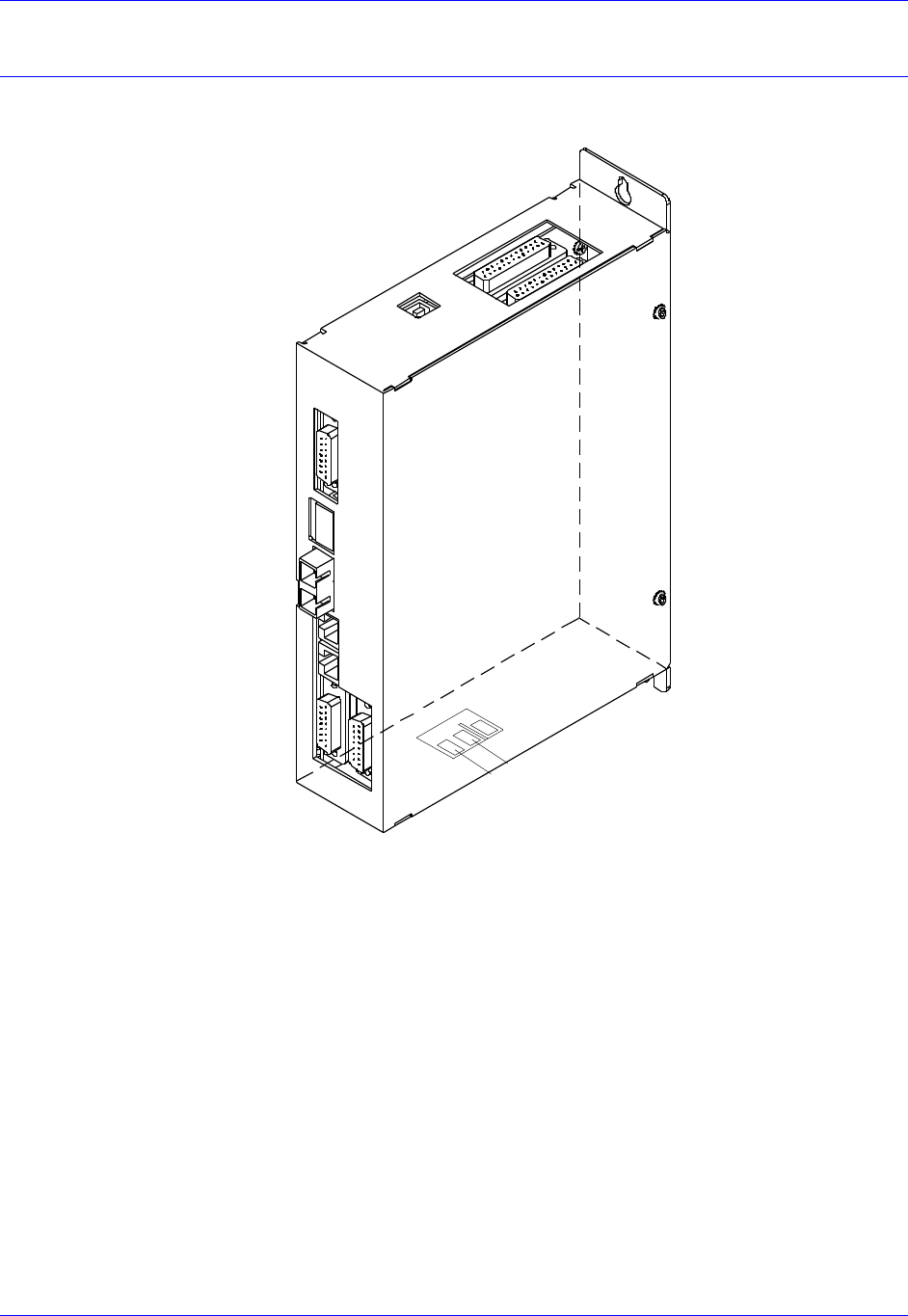
Connector Locations
Below is a drawing of the product with its connectors labeled:
J10
24VDC INPUT
J2
AMP2
J1
AMP1
Option-B
MACRO
RJ45
OUT
IN
Option-A
MACRO
FIBER
OUT
IN
J6
Flags
1&2
USB
J11 Encoder
Chan 1
J12 encoder
Chan 2
RET
+24VDC
Accessory 24M2A
Connector Pinouts 15
CONNECTOR PINOUTS
J10: 24 VDC Logic Power Input
An external 24VDC power supply is required to power the logic, flags and DAC output sections of ACC-
24M2A through the J10 connector. The polarity of this connection is extremely important. Carefully
follow the instructions in the wiring diagram. This connection can be made using 16 AWG wire directly
from a protected power supply. In situations where the power supply is shared with other devices, it may
be desirable to insert a filter in this connection.
The power supply providing this 24V must be capable of providing an instantaneous current of at least
1.5A to be able to start the DC-to-DC converter in ACC24M2A. In the case where multiple devices are
driven from the same 24V supply, it is recommended that each device be wired back to the power supply
terminals independently. It is also recommended that the power supply be sized to handle the
instantaneous inrush current required for each device.
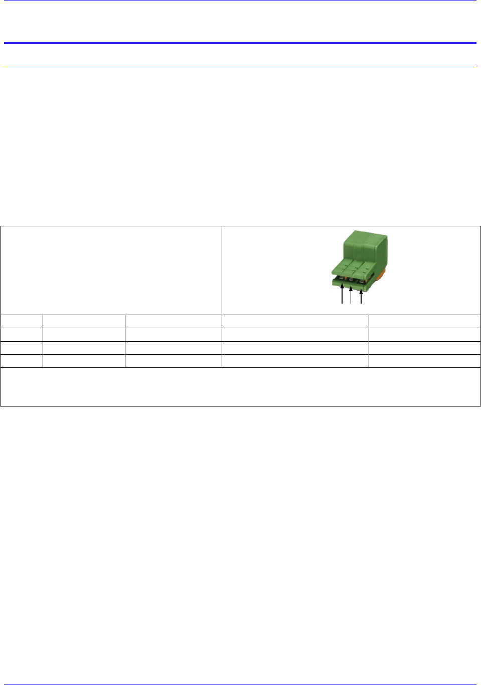
J10: 3-Pin Edge Connector
Mating: Plated Pins on ACC-24M2A PCB
123Pins:
Pin #
Symbol
Function
Description
Notes
1
24VDC RET
Common
Logic power return
2
+24VDC
Input
Logic power input
24V ±10%, 2 A
3
N.C.
N.C.
Not Connected
Connector is located at the bottom side of the unit.
Delta Tau part number: 014-188305-001
Phoenix part number: 1883051
Accessory 24M2A
Connector Pinouts 16
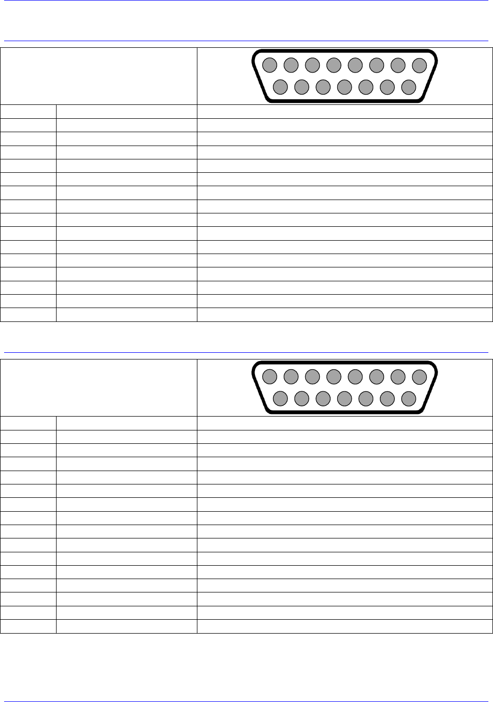
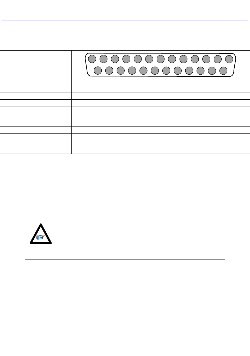
J1: Amplifier Channel 1
J1: DB-15 Female
Mating: DB-15 Male
2
3
4
5
6
7
8
9
10
11
12
13
14
15
1
Pin #
Symbol
Description
1
DAC1_A+
Phase A +analog output
2
DAC1_B+
Phase B +analog output
3
AE_NC_1
Amplifier Enabled Normally Closed
4
AE_NO_1
Amplifier Enabled Normally Open
5
AFAULT_1-
Amplifier Fault input
6
N.C.
Do not connect
7
A+12V
Analog Positive Supply Voltage
8
AGND
Analog Ground
9
DAC1_A-
Phase A +analog output
10
DAC1_B-
Phase B +analog output
11
AE_COM_1
Amplifier Enable Common
12
AFAULT_1+
Amplifier Fault input
13
N.C.
Do not connect
14
AGND
Analog Ground
15
A-12V
Analog Negative Supply Voltage
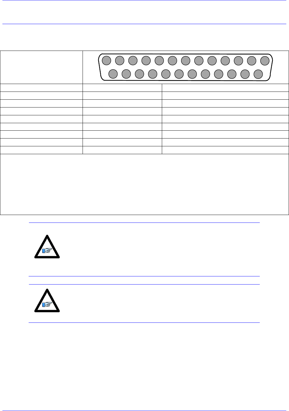
J2: Amplifier Channel 2
J1: DB-15 Female
Mating: DB-15 Male
2
3
4
5
6
7
8
9
10
11
12
13
14
15
1
Pin #
Symbol
Description
1
DAC2_A+
Phase A +analog output
2
DAC2_B+
Phase B +analog output
3
AE_NC_2
Amplifier Enabled Normally Closed
4
AE_NO_2
Amplifier Enabled Normally Open
5
AFAULT_2-
Amplifier Fault input
6
N.C.
Do not connect
7
A+12V
Analog Positive Supply Voltage
8
AGND
Analog Ground
9
DAC2_A-
Phase A +analog output
10
DAC2_B-
Phase B +analog output
11
AE_COM_2
Amplifier Enable Common
12
AFAULT_2+
Amplifier Fault input
13
N.C.
Do not connect
14
AGND
Analog Ground
15
A-12V
Analog Negative Supply Voltage

Accessory 24M2A
Connector Pinouts 17
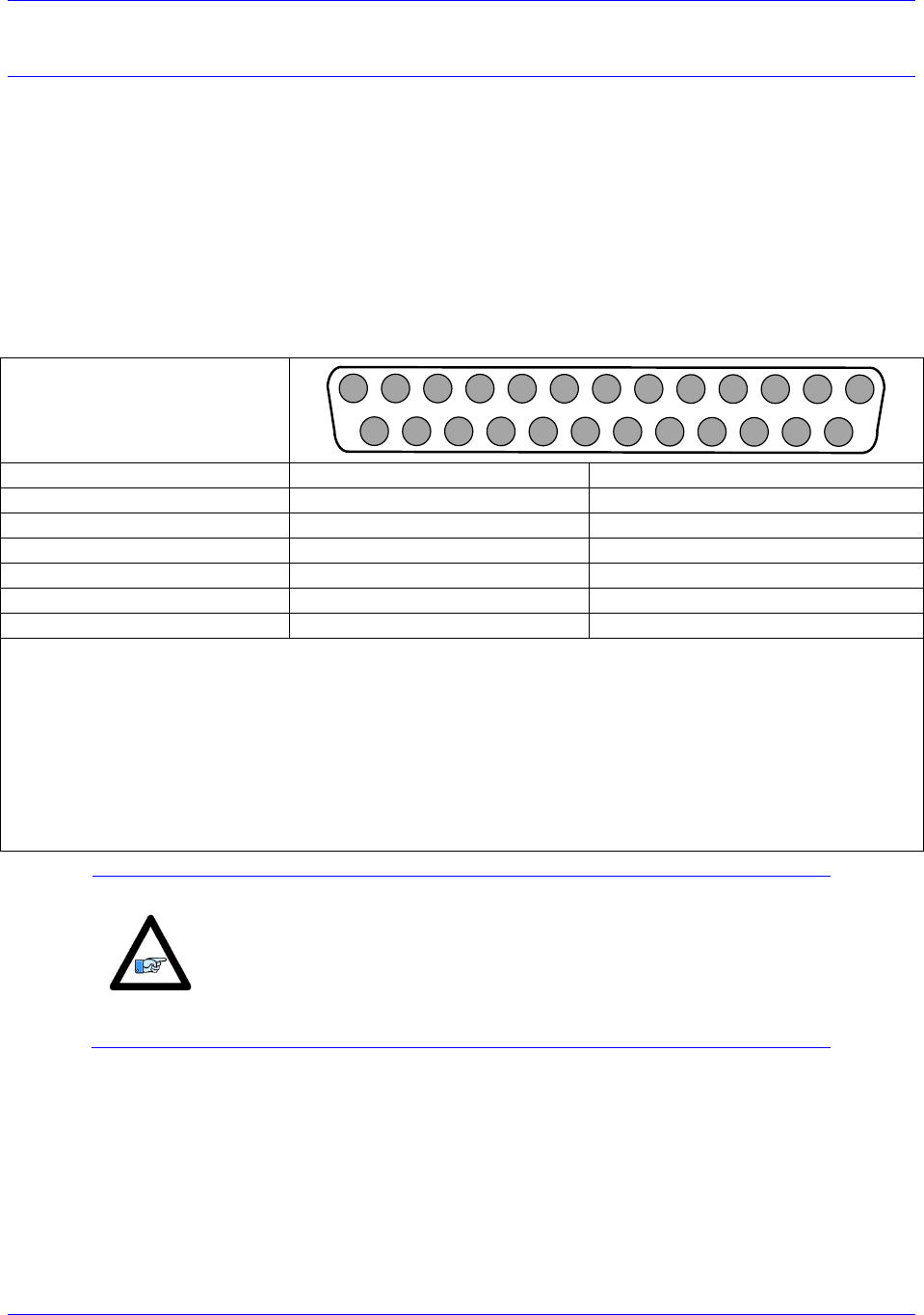
J6: Flags and Limits
J6: DB-15 Female
Mating: DB-15 Male
2
3
4
5
6
7
8
9
10
11
12
13
14
15
1
Pin #
Symbol
Direction
Description
1
USER1
Input
User Flag for Channel 1
9
PLIM1
Input
Positive Position Limit for Channel 1
2
NLIM1
Input
Negative Position Limit for Channel 1
10
HOME1
Input
Home flag for Channel 1
3
FLG_RTN1
Input
11
EQU1
Output
Position Compare Output for Channel 1
4
USER2
Input
User Flag for Channel 2
12
PLIM2
Input
Positive Position Limit for Channel 2
5
NLIM2
Input
Negative Position Limit for Channel 2
13
HOME2
Input
Home flag for Channel 2
6
FLG_RTN2
Input
14
EQU2
Output
Position Compare Output for Channel 2
7
GND
Input
Digital Ground
15
GND
Input
Digital Ground
8
GND
Input
Digital Ground
Accessory 24M2A
Connector Pinouts 18
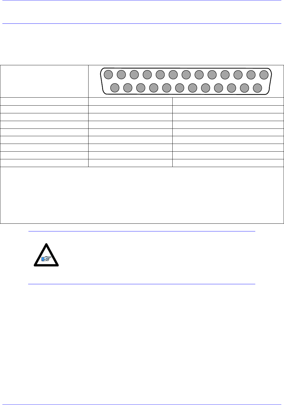
J11 & J12: Encoder Feedback, Digital A Quad B
ACC-24M2A accepts inputs from two digital encoders and provides encoder position data to PMAC. J11
is for Encoder 1 and J12 is for Encoder 2. The ACC-
differential line receivers. The differential format provides a means of using twisted pair wiring that
allows for better noise immunity when wired into machinery.
J11 & J12: D-sub DB-25F
Mating: D-sub DB-25M
1
2
3
4
5
6
7
8
9
10
11
12
13
14
15
16
17
18
19
20
21
22
23
24
25
Pin #
Symbol
Description
1
ChA+
Channel A Positive Signal
14
ChA-
Channel A Negative Signal
2
ChB+
Channel B Positive Signal
15
ChB-
Channel A Negative Signal
3
ChC+
Channel C Positive Signal
16
ChC-
Channel C Negative Signal
12 / 24*
ENCPWR/5V
Encoder Power (+5VDC)
13 / 25
GND
Digital Ground
Note:
Do not connect the pins that are not listed.
*If the encoder being used required +5VDC power, it can be connected to pins 12/24, and grounded on pins
13/25. However, if the encoder has different power requirements, do not connect pins 13/24 and 13/25 to
the encoder.
To twist the ENCPWR/5V and the GND wires together is recommended for better noise immunity.
Tie together the ACC-
used for the encoder for better noise immunity.
Note
Most applications use pin 12 to supply power to the encoder.
However, for encoders that send out initial information at power on,
the user should use pin 24 instead of pin 12, and then set MI984=1 on
ACC-24M2A in order to manually enable the encoder power after
PMAC is powered on.
Accessory 24M2A
Connector Pinouts 19
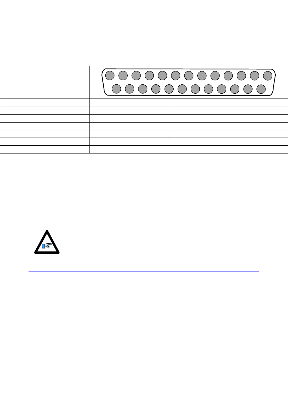
J11 & J12: Encoder Feedback, SSI
ACC-24M2A accepts inputs from two digital encoders and provides encoder position data to PMAC. J11
is for Encoder 1 and J12 is for Encoder 2. The ACC-
differential line receivers. The differential format provides a means of using twisted pair wiring that
allows for better noise immunity when wired into machinery.
J11 & J12: D-sub DB-25F
Mating: D-sub DB-25M
1
2
3
4
5
6
7
8
9
10
11
12
13
14
15
16
17
18
19
20
21
22
23
24
25
Pin #
Symbol
Description
6
CLK+
Serial Clock Signal Positive
7
DATA+
Serial Data Signal Positive
19
CLK-
Serial Clock Signal Negative
20
DATA-
Serial Data Signal Negative
12/24*
ENCPWR/5V
Encoder Power (+5VDC)
13/25
GND
Digital Ground
Note:
Do not connect the pins that are not listed.
*If the encoder being used required +5VDC power, it can be connected to pins 12/24, and grounded on pins
13/25. However, if the encoder has different power requirements, do not connect pins 13/24 and 13/25 to
the encoder.
To twist the ENCPWR/5V and the GND wires together is recommended for better noise immunity.
Tie together the ACC-
used for the encoder for better noise immunity.
Note
Most applications use pin 12 to supply power to the encoder.
However, for encoders that send out initial information at power on,
the user should use pin 24 instead of pin 12, and then set MI984=1 on
ACC-24M2A in order to manually enable the encoder power after
PMAC is powered on.
Accessory 24M2A
Connector Pinouts 20
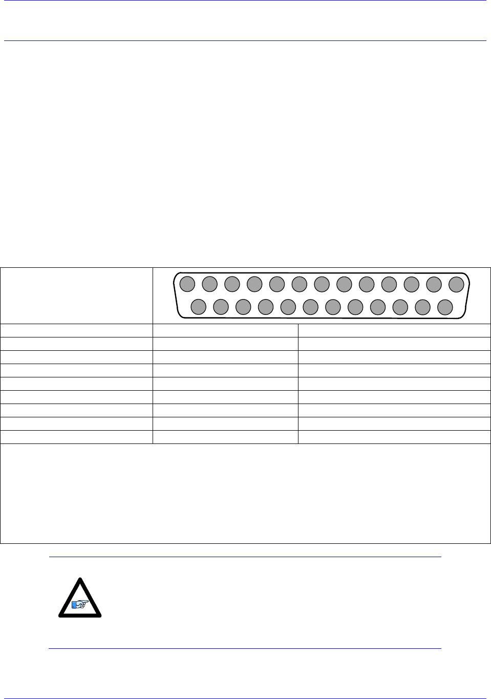
J11 & J12: Encoder Feedback, Sinusoidal
ACC-24M2A accepts inputs from two digital encoders and provides encoder position data to PMAC. J11
is for Encoder 1 and J12 is for Encoder 2. The ACC-
differential line receivers. The differential format provides a means of using twisted pair wiring that
allows for better noise immunity when wired into machinery.
Acc-24M2A with the Sinusoidal Interpolator option accepts inputs from two sinusoidal or quasi-
sinusoidal encoders and provides encoder position data to the motion processor. This interpolator creates
4,096 steps per sine-wave cycle. The user must order the appropriate option. ACC-24M2A can be used
only with a voltage mode sinusoidal encoder type.
Be sure to use shielded, twisted pair cabling for sinusoidal encoder wiring. Double insulated is the best
choice. The sinusoidal signals are very small and must be kept as noise free as possible. Avoid cable
routing near noisy motor or driver wiring. Refer to the appendix for tips on encoder wiring.
It is possible to reduce noise in the encoder lines of a motor-based system by the use of inductors that are
placed between the motor and the amplifier. Improper grounding techniques may also contribute to noisy
encoder signals.
J11 & J12: D-sub DB-25F
Mating: D-sub DB-25M
1
2
3
4
5
6
7
8
9
10
11
12
13
14
15
16
17
18
19
20
21
22
23
24
25
Pin #
Symbol
Description
1
Sin+
Sinusoidal Signal Positive
14
Sin-
Sinusoidal Signal Negative
2
Cos+
Cosine Signal Positive
15
Cos-
Cosine Signal Negative
3
Index+
Index Pulse Signal Positive
16
Index-
Index Pulse Signal Negative
12/24*
ENCPWR/5V
Encoder Power (+5VDC)
13/25
GND
Ground
Note:
Do not connect the pins that are not listed.
*If the encoder being used required +5VDC power, it can be connected to pins 12/24, and grounded on pins
13/25. However, if the encoder has different power requirements, do not connect pins 13/24 and 13/25 to
the encoder.
To twist the ENCPWR/5V and the GND wires together is recommended for better noise immunity.
Tie together the ACC-
used for the encoder for better noise immunity.
Note
Most applications use pin 12 to supply power to the encoder.
However, for encoders that send out initial information at power on,
the user should use pin 24 instead of pin 12, and then set MI984=1 on
ACC-24M2A in order to manually enable the encoder power after
PMAC is powered on.
Accessory 24M2A
Connector Pinouts 21
J11 & J12: Encoder Feedback, EnDat
The Acc-24M2A will read the absolute data from the EnDat (Encoder Data) interface only if the
appropriate option is ordered. Its differential format provides a means of using twisted-pair wiring that
allows for better noise immunity when wired into machinery.
J11 & J12: D-sub DB-25F
Mating: D-sub DB-25M
1
2
3
4
5
6
7
8
9
10
11
12
13
14
15
16
17
18
19
20
21
22
23
24
25
Pin #
Symbol
Description
1
Sin+/ ChA+
Sinusoidal Signal Positive/Channel A Positive
2
Cos+/ChB+
Cosine Signal Positive/Channel B Positive
14
Sin-/ChA-
Sinusoidal Signal Negative/Channel A Negative
15
Cos-/ChB-
Cosine Signal Negative/Channel B Negative
6
CLK+
Clock Signal Positive
7
DATA+
Data Signal Positive
19
CLK-
Clock Signal Negative
20
DATA-
Data Signal Negative
12/24
ENCPWR/5V
Encoder Power (+5VDC)
13/25
GND
Ground
Note:
Do not connect the pins that are not listed.
*If the encoder being used required +5VDC power, it can be connected to pins 12/24, and grounded on pins
13/25. However, if the encoder has different power requirements, do not connect pins 13/24 and 13/25 to
the encoder.
To twist the ENCPWR/5V and the GND wires together is recommended for better noise immunity.
Tie together the ACC-
used for the encoder for better noise immunity.
Note
Most applications use pin 12 to supply power to the encoder.
However, for encoders that send out initial information at power on,
the user should use pin 24 instead of pin 12, and then set MI984=1 on
ACC-24M2A in order to manually enable the encoder power after
PMAC is powered on.
Accessory 24M2A
Connector Pinouts 22
J11 & J12: Encoder Feedback, HiperFace
ACC-24M2A will read the absolute data from the Hiperface® interface only if the appropriate option is
ordered.
J11 & J12: D-sub DB-25F
Mating: D-sub DB-25M
1
2
3
4
5
6
7
8
9
10
11
12
13
14
15
16
17
18
19
20
21
22
23
24
25
Pin #
Symbol
Description
1
Sin+/ ChA+
Sinusoidal Signal Positive/Channel A Positive
2
Cos+/ChB+
Cosine Signal Positive/Channel B Positive
14
Sin-/ChA-
Sinusoidal Signal Negative/Channel A Negative
15
Cos-/ChB-
Cosine Signal Negative/Channel B Negative
7
DATA+
Clock Signal Positive
20
DATA-
Data Signal Positive
12/24
ENCPWR/5V
Clock Signal Negative
13/25
GND
Data Signal Negative
Note:
Do not connect the pins that are not listed.
*If the encoder being used required +5VDC power, it can be connected to pins 12/24, and grounded on pins
13/25. However, if the encoder has different power requirements, do not connect pins 13/24 and 13/25 to
the encoder.
To twist the ENCPWR/5V and the GND wires together is recommended for better noise immunity.
Tie together the ACC-
used for the encoder for better noise immunity.
Note
Most applications use pin 12 to supply power to the encoder.
However, for encoders that send out initial information at power on,
the user should use pin 24 instead of pin 12, and then set MI984=1 on
ACC-24M2A in order to manually enable the encoder power after
PMAC is powered on.
Note
As of the date of the latest revision of this manual, HiperFace is not
yet part of the ACC-24M2A firmware.
Accessory 24M2A
Connector Pinouts 23
J11 & J12: Encoder Feedback, Resolver
The ACC-24M2A can interface to most industry standard resolvers if the appropriate option is ordered.
Typical resolvers requiring 5 to 10 kHz excitation frequencies with voltages ranging from 5 to 10 V peak-
to-peak are compatible with this drive.
Fundamentally, the ACC-24M2A connects three differential analog signal pairs to each resolver: a single
excitation signal pair, and two analog feedback signal pairs. The wiring diagram below shows an
example of how to connect the ACC-24M2A to the Resolver.
The differential format provides a means of using twisted pair wiring that allows for better noise
immunity when wired into machinery.
J11 & J12: D-sub DB-25F
Mating: D-sub DB-25M
1
2
3
4
5
6
7
8
9
10
11
12
13
14
15
16
17
18
19
20
21
22
23
24
25
Pin #
Symbol
Description
4
ResSin+
Resolver Sine Positive
17
ResSin-
Resolver Sine Negative
5
ResCos+
Resolver Cosine Positive
18
ResCos-
Resolver Cosine Negative
11
ResOut
Resolver Output
13/25
GND
GND
Note:
Do not connect the pins that are not listed.
*If the encoder being used required +5VDC power, it can be connected to pins 12/24, and grounded on pins
13/25. However, if the encoder has different power requirements, do not connect pins 13/24 and 13/25 to
the encoder.
To twist the ENCPWR/5V and the GND wires together is recommended for better noise immunity.
Tie together the ACC-
used for the encoder for better noise immunity.
Note
Most applications use pin 12 to supply power to the encoder.
However, for encoders that send out initial information at power on,
the user should use pin 24 instead of pin 12, and then set MI984=1 on
ACC-24M2A in order to manually enable the encoder power after
PMAC is powered on.

Accessory 24M2A
Connector Pinouts 24
Universal Serial Bus Port (USB Port)
This connector uses a USB A-B cable to establish communication between the PC and the ACC-24M2A.
This type of USB cable could be purchased at any local electronics or computer store. It may be ordered
from Delta Tau as well.
Pin #
Symbol
Function
1
VCC
N.C.
2
D-
DATA-
3
D+
DATA+
4
GND
GND
5
SHELL
SHIELD
6
SHELL
SHIELD
This connector is used only to change the operational firmware, or to perform basic software diagnostic
operations. The user can use a serial port terminal window such as Microsoft® HyperTerminal to
communicate with the MACRO Device and send ASCII commands to the device. Set the serial port
communication settings as follows:
Baud Rate: 38400 if E3 is not jumpered, or 9600 if E3 is jumpered
Data Bits: 8
Parity: None
Stop Bits: 1
Flow Control: Xon/Xoff
If the PeWin32PRO2 software is installed on the PC, then the USB device should be recognized by the
operating system. If the device is not recognized, then contact Technical Support for assistance.
Accessory 24M2A
Connector Pinouts 25
MACRO Fiber Connector
Option A provides the following connector for MACRO communications:
MACRO SC-Style Fiber Connector
OUT IN
Front View
Pin #
Symbol
Function
1
IN
MACRO Ring Receiver
2
OUT
MACRO Ring Transmitter
Notes: The fiber optic version of MACRO uses 62.5/125 multi-mode glass fiber optic cable terminated in an SC-style connector.
The optical wavelength is 1,300 nm.
The input connector must be inserted into the MACRO output connector of the previous device on the
MACRO ring. The output connector must be inserted into the input MACRO connector of the next
device on the MACRO ring.
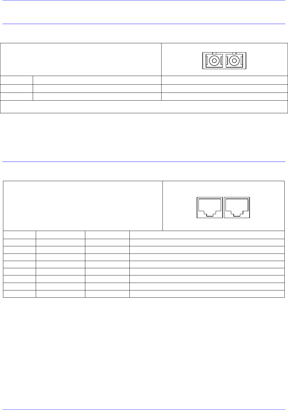
MACRO RJ-45 Copper Connector
Option C Provides the following connector for MACRO communications:
Connector: RJ45 CAT5e
Mating: RJ45 Receptacle
OUT IN
Front View
Pin #
Symbol
Function
Description
1
DATA+
Data +
Differential MACRO Signal
2
DATA-
Data -
Differential MACRO Signal
3
Unused
Unused terminated pin
4
Unused
Unused terminated pin
5
Unused
Unused terminated pin
6
Unused
Unused terminated pin
7
Unused
Unused terminated pin
8
Unused
Unused terminated pin
The cable used for MACRO wired connections is CAT5 verified straight-through 8 conductor.
The input connector must be inserted into the MACRO output connector of the previous device on the
MACRO ring. The output connector must be inserted into the input MACRO connector of the next
device on the MACRO ring.
Accessory 24M2A
Connector Pinouts 26
Sample Wiring Diagrams
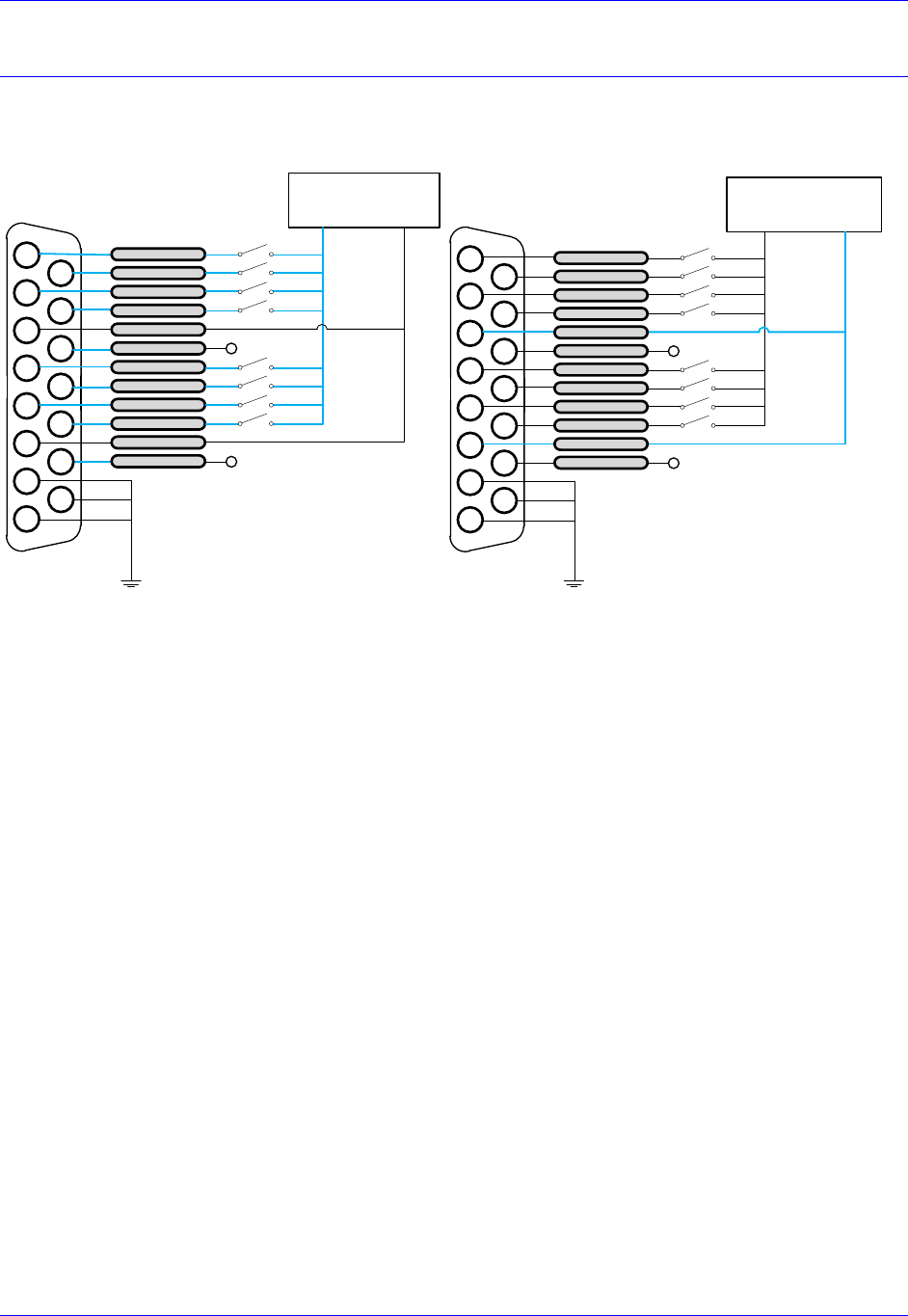
J6: Flags
Sourcing Flags Sinking Flags
2345678 1
1011121315 9
0 or 12-24 VDC
Power Supply
USER1
PLIM1
FLAG RET 1
EQU1
USER2
PLIM2
MLIM2
HOME2
FLAG RET2
EQU2
MLIM1
HOME1
14
+5 or 12-24 VDC
0 VDC
2345678 1
1011121315 9
5 or 12-24 VDC
Power Supply
USER1
PLIM1
FLAG RET 1
EQU1
USER2
PLIM2
MLIM2
EQU2
MLIM1
HOME1
14
0 VDC
+5 or 12-24 VDC
FLAG RET2
HOME2
Accessory 24M2A
Connector Pinouts 27
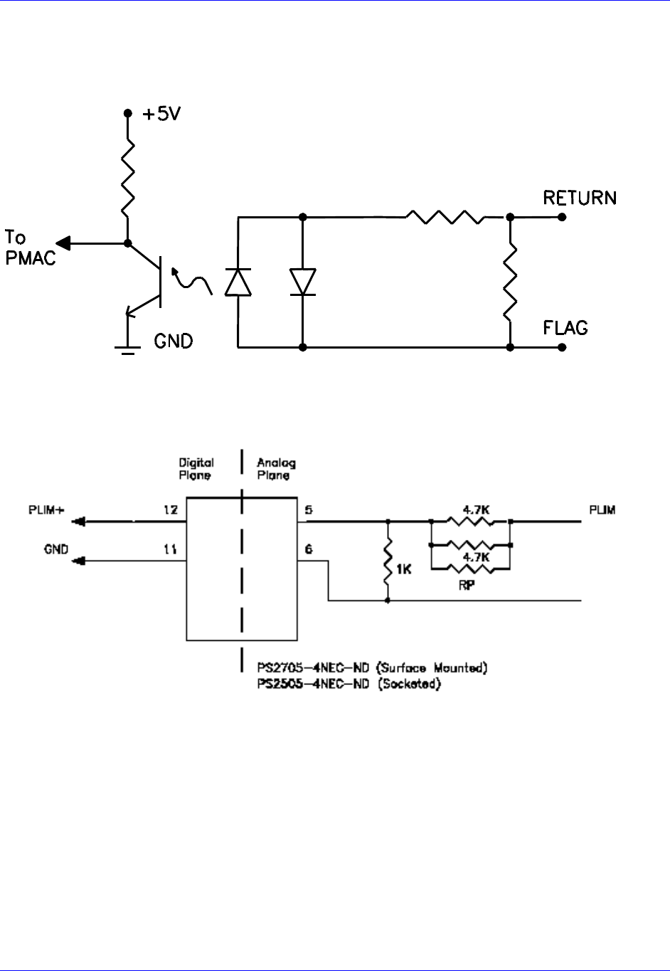
Output IC Diagram
ACC-24M2A allows the use of sinking or sourcing position limits and flags to the controller. The opto-
isolator IC used is a PS2705-4NEC-ND quad phototransistor output type (see below).
This IC allows the current to flow from return to flag (sinking) or from flag to return (sourcing).
A sample of the internal positive limit circuit for this IC is shown below.
The 4.7K resistor packs used will allow 1224V flag inputs. If the user wants to use 05V flags, then a
1K resistor pack (RP) can be placed in RP7 for CC
these resistor packs are not added, all flags ( Limits, Home, User, and Amplifier Fault) will be
referenced from 1224V.
Accessory 24M2A
Connector Pinouts 28
J11 & J12: Encoder Feedback, Digital A Quad B
The following wiring diagram shows an example of how to connect a quadrature encoder:
2
3
4
5
14
15
16
17
1
6
7
18
19
8
9
20
21
10
11
22
23
12
13
24
25
Quadrature
Encoder
CHA+
CHA-
CHB+
CHB-
CHC+
CHC-
GND
5V
Shield
J11 & J12: Encoder Feedback, SSI
2
3
4
5
14
15
16
17
1
6
7
18
19
8
9
20
21
10
11
22
23
12
13
24
25
CLK+
DAT+
DAT-
CLK- SSI
encoder
Shield
+5V
GND
Accessory 24M2A
Connector Pinouts 29
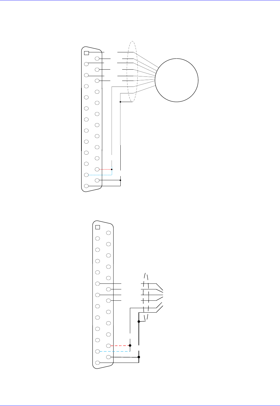
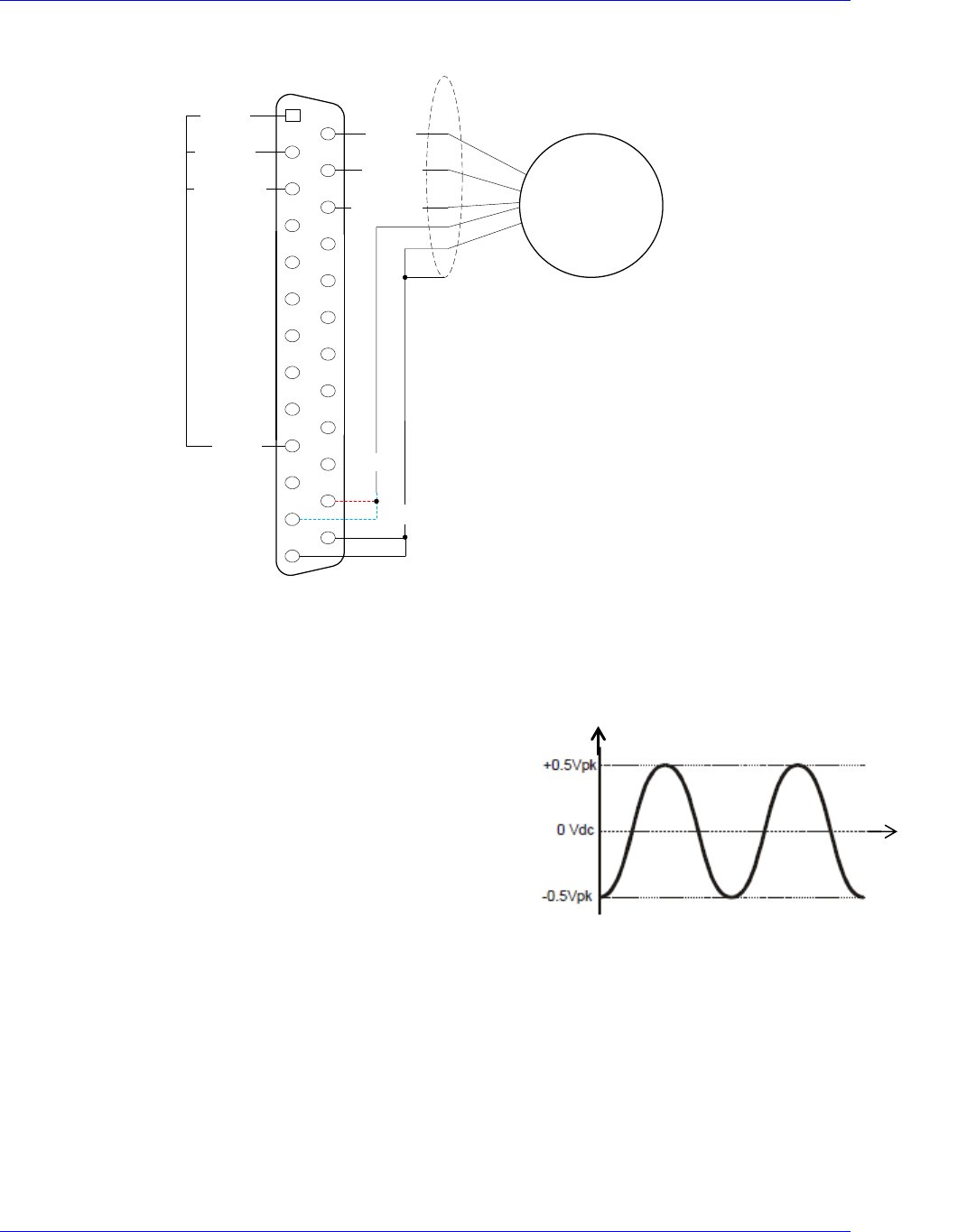
J11 & J12: Encoder Feedback, Sinusoidal
Differential Format
The differential format provides a means of using twisted pair wiring that allows for better noise
immunity when wired into machinery.
2
3
4
5
14
15
16
17
1
6
7
18
19
8
9
20
21
10
11
22
23
12
13
24
25
Sinusoidal
Encoder
SIN+
SIN-
COS+
COS-
INDEX+
INDEX-
GND
5V
Shield
Single Ended Format 1
The single-ended formats provide a simpler means of using a sinusoidal encoder. Typically, fewer wires
are needed and the encoders are always of the lower impedance voltage output type.
Note that all the single-ended encoder formats shown
here might have velocity-ripple effects at very slow
speeds due to the effects of op-amp voltage offsets.
These offsets cause the sinusoidal signal to be centered
at a value that is slightly different from the reference or
servo ground as shown in the signal diagram on the right:
Time [s]
Encoder Output [V]
Accessory 24M2A
Connector Pinouts 30
Below is the wiring diagram for Single Ended Format 1:
2
3
4
5
14
15
16
17
1
6
7
18
19
8
9
20
21
10
11
22
23
12
13
24
25
Sinusoidal
Encoder
SIN-
COS-
INDEX-
GND
5V
Shield
SIN+
COS+
INDEX+
REV
2.5V
SIN-
COS-
INDEX-
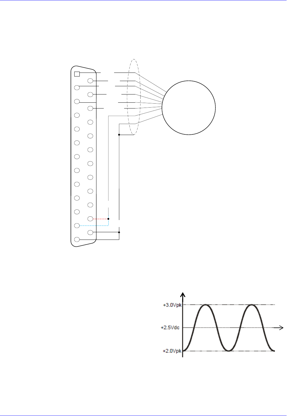
Single Ended Format 2
The diagram shown below is a simple single-ended encoder-wiring interface for encoders with output
range at 2-3 Vdc. This encoder has SIN and COS outputs that provide a 1V peak-to-peak output with a
voltage offset of 2.5 Vdc. Note that the SIN+, COS+, and INDEX+ lines are tied to the 2.5V internal
references on the interpolator card.
The diagram to the right is similar to the signal diagram from
the Single Ended Format 1 but with a different voltage offset.
This encoder has SIN and COS outputs that provide a 1V peak-
to-peak output with a voltage offset of 0.0 Vdc. Note that the
SIN-, COS-, and INDEX- lines are tied to the GND on the
interpolator card, and the encoder usually requires a bipolar
supply.
Time [s]
Encoder Output [V]
Accessory 24M2A
Connector Pinouts 31
The wiring diagram for Single Ended Format 2 is below:
2
3
4
5
14
15
16
17
1
6
7
18
19
8
9
20
21
10
11
22
23
12
13
24
25
Sinusoidal
Encoder
SIN-
COS-
INDEX-
GND
Shield
SIN+
COS+
INDEX+
SIN-
COS-
GND
+Vdc
- Vdc
GND
Noise Problems
When problems do occur, the culprit is often electrical noise. When this occurs, attempt to control the
high-frequency current paths. If following the grounding instructions does not work, insert chokes in the
motor phases. These chokes can be as simple as several wraps of the individual motor leads through a
ferrite ring core (such as Micrometals T400-26D). This adds high-frequency impedance to the outgoing
motor cable thereby impeding high-frequency noise from leaving the control cabinet. Care should be
Accessory 24M2A
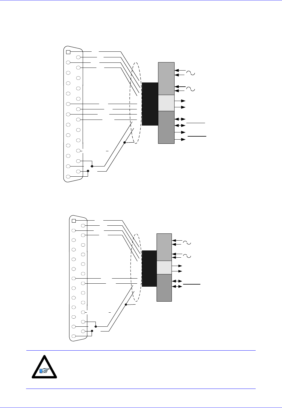
Connector Pinouts 32
J11 & J12: Encoder Feedback, EnDat
2
3
4
5
14
15
16
17
1
6
7
18
19
8
9
20
21
10
11
22
23
12
13
24
25
EnDat Interface
Sin+
Cos-
Sin-
Cos+
+5V
GND
Shield
In_Therm_Mot
DATA
DATA
CLOCK
CLOCK
1Vpp A
1Vpp B
EnDat Interface
Up Power
0V Supply
CLK+
DATA+
DATA-.
CLK-
J11 & J12: Encoder Feedback, HiperFace
2
3
4
5
14
15
16
17
1
6
7
18
19
8
9
20
21
10
11
22
23
12
13
24
25
Hiperface® Interface
Sin+
Cos-
Sin-
Cos+
+5V
GND
Shield
In_Therm_Mot
DATA
DATA
1Vpp A
1Vpp B
Hiperface Interface
Up Power
0V Supply
DATA+
DATA-
Note
As of the date of the latest revision of this manual, HiperFace is not
yet part of the ACC-24M2A firmware.
Accessory 24M2A
Connector Pinouts 33
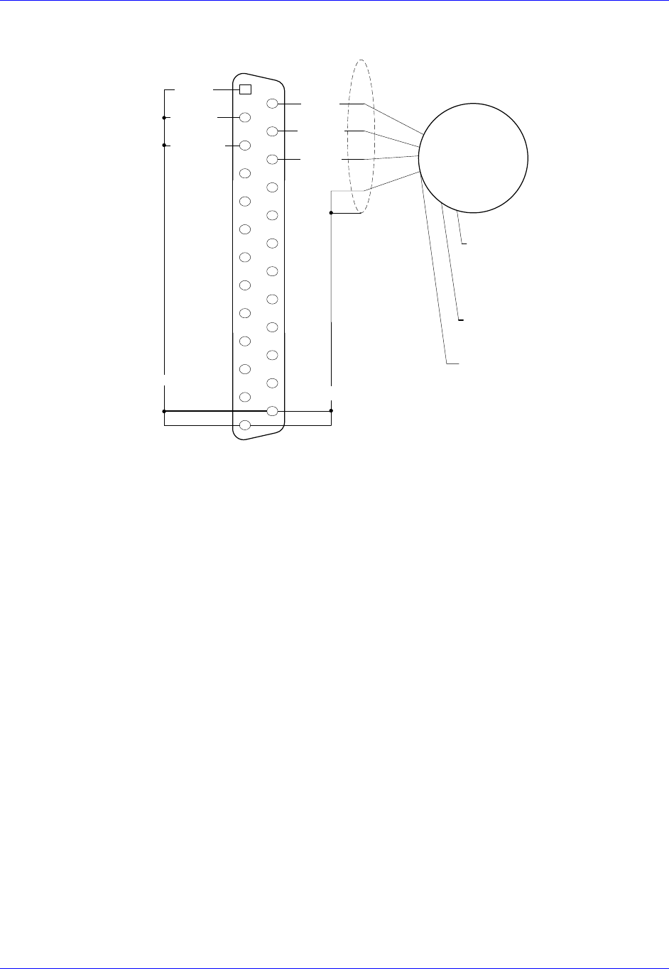
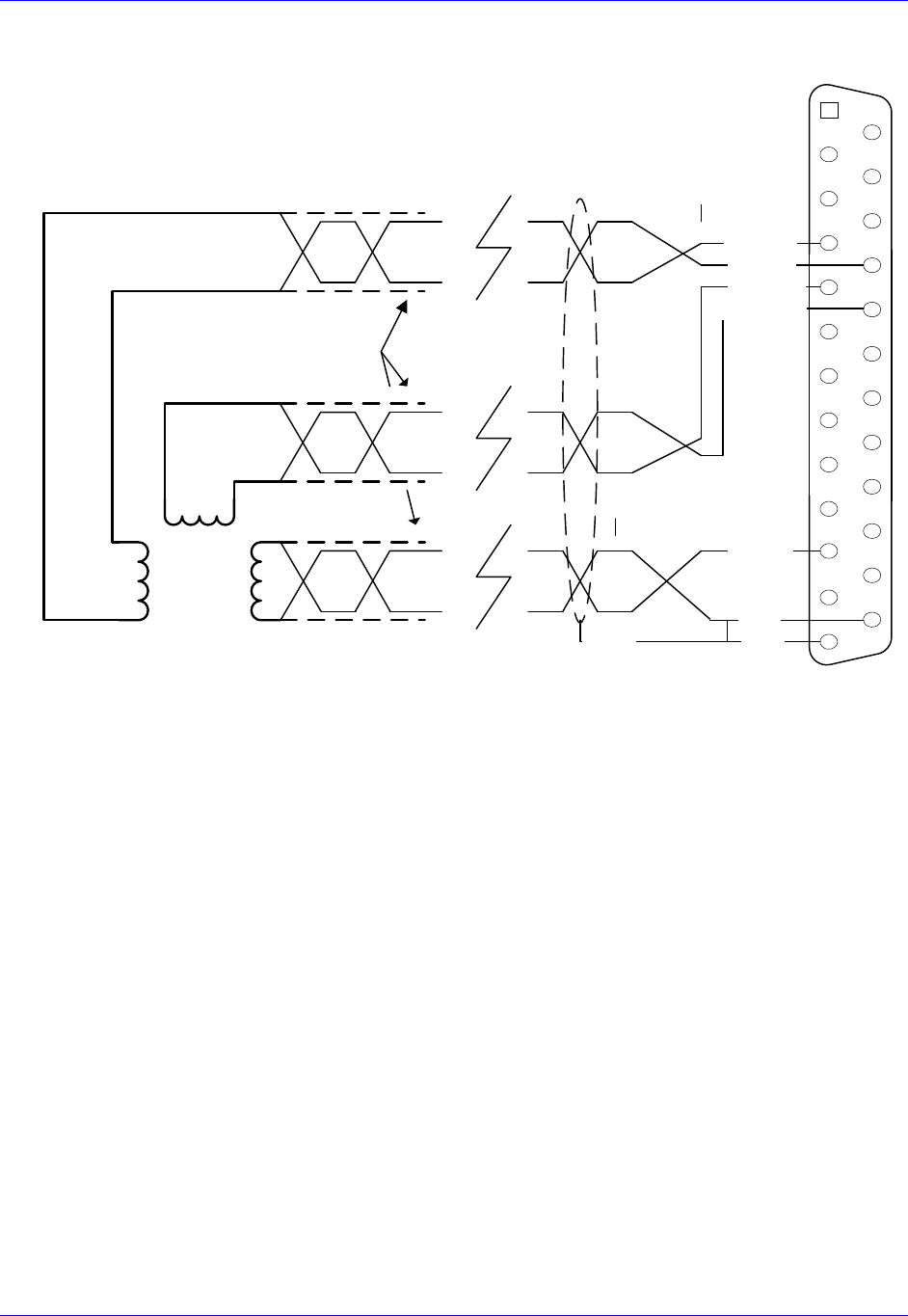
J11 & J12: Encoder Feedback, Resolver
ResOut
GND
Sin+
Sin-
Cos+
Cos-
Notes:
Terminate shields on pins 13 and 25
Twisted pair Screened
Cable
2
3
4
5
14
15
16
17
1
6
7
18
19
8
9
20
21
10
11
22
23
12
13
24
25
ResOut
ResSin+
ResSin-
GND
GND
Shield
ResCos-.
ResCos+
Resolver ACC-24M2A

Accessory 24M2A
Troubleshooting 34
TROUBLESHOOTING
Status LED Indicators
Status Display
Color
Description
7-segment LED
Red
16 numeric codes plus two decimal points
PWR
Green
Lit when logic power is good
WD
Red
Indicates that the watchdog safety circuit has
activated, indicating a failure condition.
7-Segment LED Indicator
This indicator reports the status of the unit with respect to the MACRO link, indicating the value of
MI974. These are the possible status codes:
7-Segment LED
Display
Description
Notes/Cause
0
Ring Active with no errors
Normal Operation with decimal point blinking
1
One (1) Amp Enable output
activated
If an amplifier/motor is connected, it is potentially
activated in either open or closed loop form. Exercise
caution.
2
Two (1) Amp Enable outputs
activated
If an amplifier/motor is connected, it is potentially
activated in either open or closed loop form. Exercise
caution.
3-9
NA
NA
A
Amplifier Fault
Denotes Amplifier fault condition true. Cleared by
enabling amplifier or CLRF.
B
MACRO Ring Break Fault
Break or misconnection in fiber optic or RJ45 ring
termination.
C
Configuration change fault
Denotes mismatch between master and slave node
configuration. Check MI996 and I6806, etc. for match.
Clear with CLRF.
D
MACRO Ring Fault
Ring Data-Error Fault. Too many ring errors or not
enough synch packets being received. Node 15 may not
be properly enabled.
E
Encoder Fault
Encoder Loss bit condition true (MI927=1). Occurs
only when Encoder Loss detection is enabled. Denotes
loss of encoder signal. Check encoder wiring and
functionality.
F
NA
NA
D1
5082-7730
11
6
14
1
13
10
8
3
7
2G
DPR
VCC
A
B
C
D
VCC
E
F
Accessory 24M2A
Configuring with Turbo PMAC 35
CONFIGURING WITH TURBO PMAC
Quick Review: Nodes and Addressing
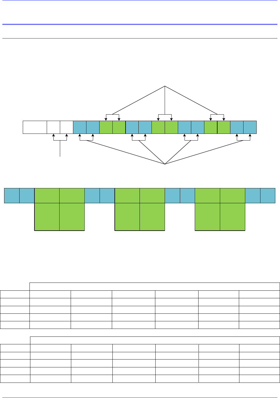
Each MACRO IC consists of 16 nodes: 2 auxiliary, 8 servo, and 6 I/O nodes.
Auxiliary nodes are Master/Control registers and internal firmware use.
Servo nodes carry information such as feedback, commands, and flags for motor control.
I/O nodes are by default unoccupied and are user configurable for transferring miscellaneous data.
15 14 13 12 11 10 9 8 7 6 5 4 3 2 1 0Node
Auxiliary
Nodes
I/O Nodes
Servo Nodes
Each I/O node consists of 4 registers; one 24-bit and three 16-bit registers for a total of 72 bits of data.
5 4 2 1 0
24-bit
1st 16-bit
2nd 16-bit
3rd 16-bit
3
24-bit
1st 16-bit
2nd 16-bit
3rd 16-bit
6
24-bit
1st 16-bit
2nd 16-bit
3rd 16-bit
7
24-bit
1st 16-bit
2nd 16-bit
3rd 16-bit
9 810
24-bit
1st 16-bit
2nd 16-bit
3rd 16-bit
11
24-bit
1st 16-bit
2nd 16-bit
3rd 16-bit
13 12
A given MACRO Station can be populated with either a MACRO8 or MACRO16 CPU:
MACRO8 supports only 1 MACRO IC (IC#0).
MACRO16 supports 2 MACRO ICs (IC#0 and IC#1).
The I/O node addresses ($C0XX) for each of the Station MACRO ICs are:
Station MACRO IC #0 Node Registers
Node
2
3
6
7
10
11
24-bit
X:$C0A0
X:$C0A4
X:$C0A8
X:$C0AC
X:$C0B0
X:$C0B4
16-bit
X:$C0A1
X:$C0A5
X:$C0A9
X:$C0AD
X:$C0B1
X:$C0B5
16-bit
X:$C0A2
X:$C0A6
X:$C0AA
X:$C0AE
X:$C0B2
X:$C0B6
16-bit
X:$C0A3
X:$C0A7
X:$C0AB
X:$C0AF
X:$C0B3
X:$C0B7
Station MACRO IC #1 Node Registers
Node
2
3
6
7
10
11
24-bit
X:$C0E0
X:$C0E4
X:$C0E8
X:$C0EC
X:$C0F0
X:$C0F4
16-bit
X:$C0E1
X:$C0E5
X:$C0E9
X:$C0ED
X:$C0F1
X:$C0F5
16-bit
X:$C0E2
X:$C0E6
X:$C0EA
X:$C0EE
X:$C0F2
X:$C0F6
16-bit
X:$C0E3
X:$C0E7
X:$C0EB
X:$C0EF
X:$C0F3
X:$C0F7

Accessory 24M2A
Configuring with Turbo PMAC 36
Note
Non-Turbo PMAC2 Ultralite (legacy) I/O node addresses are the same
as Station MACRO IC#0 node registers.
A given Turbo PMAC2 Ultralite (or UMAC with ACC-5E) can be
populated with up to 4 MACRO ICs (IC#0, IC#1, IC#2, and IC#3)
which can be queried with global variable I4902:
If I4902=
Populated
MACRO IC #s
$0
None
$1
0
$3
0, 1
$7
0, 1, 2
$F
0, 1, 2, 3
And the I/O node addresses ($7XXXX) for each of the Ultralite MACRO ICs are:
Ring Controller MACRO IC #0 Node Registers
Station I/O Node#
2
3
6
7
10
11
Ultralite I/O Node#
2
3
6
7
10
11
24-bit
X:$78420
X:$78424
X:$78428
X:$7842C
X:$78430
X:$78434
16-bit
X:$78421
X:$78425
X:$78429
X:$7842D
X:$78431
X:$78435
16-bit
X:$78422
X:$78426
X:$7842A
X:$7842E
X:$78432
X:$78436
16-bit
X:$78423
X:$78427
X:$7842B
X:$7842F
X:$78433
X:$78437
Ring Controller MACRO IC #1 Node Registers
Station I/O Node#
2
3
6
7
10
11
Ultralite I/O Node#
18
19
22
23
26
27
24-bit
X:$79420
X:$79424
X:$79428
X:$7942C
X:$79430
X:$79434
16-bit
X:$79421
X:$79425
X:$79429
X:$7942D
X:$79431
X:$79435
16-bit
X:$79422
X:$79426
X:$7942A
X:$7942E
X:$79432
X:$79436
16-bit
X:$79423
X:$79427
X:$7942B
X:$7942F
X:$79433
X:$79437
Ring Controller MACRO IC #2 Node Registers
Station I/O Node#
2
3
6
7
10
11
Ultralite I/O Node#
34
35
38
39
42
43
24-bit
X:$7A420
X:$7A424
X:$7A428
X:$7A42C
X:$7A430
X:$7A434
16-bit
X:$7A421
X:$7A425
X:$7A429
X:$7A42D
X:$7A431
X:$7A435
16-bit
X:$7A422
X:$7A426
X:$7A42A
X:$7A42E
X:$7A432
X:$7A436
16-bit
X:$7A423
X:$7A427
X:$7A42B
X:$7A42F
X:$7A433
X:$7A437
Ring Controller MACRO IC #3 Node Registers
Station I/O Node#
2
3
6
7
10
11
Ultralite I/O Node#
50
51
54
55
58
59
24-bit
X:$7B420
X:$7B424
X:$7B428
X:$7B42C
X:$7B430
X:$7B434
16-bit
X:$7B421
X:$7B425
X:$7B429
X:$7B42D
X:$7B431
X:$7B435
16-bit
X:$7B422
X:$7B426
X:$7B42A
X:$7B42E
X:$7B432
X:$7B436
16-bit
X:$7B423
X:$7B427
X:$7B42B
X:$7B42F
X:$7B433
X:$7B437

Accessory 24M2A
Configuring with Turbo PMAC 37
Setup Overview
This setup assumes that the Ring Master has already been properly configured to run its own local
motors.
In order to set up ACC-24M2A with Turbo PMAC, one must:
1. On the Ring Master, enable one (if ACC-24M2A will only use one motor) to two (using two
motors) servo nodes (any two unused servo nodes) per ACC-24M2A
Variables involved:
I6840/I6890/I6940/I6990 — MACRO IC Ring Configuration/Status
I6841/I6891/I6941/I6991 — MACRO IC Node Activate Control
Also, make sure I78 and I80I82 have been properly configured on the Master.
2. Establish communication between the Master and the ACC-24M2A using MACRO ASCII Mode
and enable one or two servo nodes on ACC-24M2A.
Variables involved:
MS{anynode},MI11 MACRO Station Station Number
MS{anynode},MI995 MACRO Ring Configuration/Status
MS{anynode},MI996 MACRO Node Activate Control
3. Set up Feedback.
4. Set up Flag and Output Command Registers.
5. Configure I2T Protection.
6. Perform an Open Loop Test.
7. Tune the Servo Loop.

Accessory 24M2A
Configuring with Turbo PMAC 38
Setup Step 1: MACRO Connectivity
ACC-24M2A requires that the same number of servo nodes be activated through I6841 as there are
motors being used on ACC-24M2A; e.g. two servo nodes should be enabled on the Ring Controller if
using two motors, one servo node if using only one motor. I80I82 and I70I71 must also be configured.
There is a specific set of formulas to use for configuring these, as shown in the following example.
Example: Setting up nodes 0 and 1 to control one ACC-24M2A
#define RingCheckPeriod 20 ; Suggested Ring Check Period [msec]
#define FatalPackErr 10 ; Suggested Fatal Packet Error Percentage [%]
I80=INT(RingCheckPeriod *8388607/I10+1) ; Macro Ring Check Period [Servo Cycles]
I81=INT(I80/(I8+1)* FatalPackErr /100) ; Macro Maximum Ring Error Count
I82=INT(I80/(I8+1)*(100-FatalPackErr)/100) ; Macro Minimum Sync Packet Count
I6841=$FC003 // Enable nodes 0 and 1, MACRO IC 0 is master
I6840=$4030 // MACRO IC 0 transmits clocks
// for I70 and I71, use the formula I70=MI996 & $3333, I71=MI996 & $3333 //
MSR0,MI996,P33 // Obtain MI996’s value and store it in P33
I70=P33&$3333 // Enable flag transfer for nodes 0 and 1
I71= P33&$3333 // Enable flag transfer for nodes 0 and 1
Before proceeding, type SAVE, and then $$$.

Accessory 24M2A
Configuring with Turbo PMAC 39
Setup Step 2: Communicating with ACC-24M2A over MACRO ASCII
ACC-24M2A has no rotary switches to determine its MACRO Station Number. Therefore, ACC-24M2A
uses the Ring Order method to obtain its Station Number. Before the ACC-24M2A has been initialized, it
will by default be at MACRO Station #255.
If ACC-24M2A is not at factory default, the user can reinitialize it as follows:
If using MACRO IC #0, to reinitialize ACC-24M2A, type MS$$$***15, then MSSAV15, then
MS$$$15.
If using MACRO IC #1, type MS$$$***31, then MSSAV31, then MS$$$31.
If using MACRO IC #2, use MS$$$***47, then MSSAV47, then MS$$$47, and so on for other
MACRO IC #s.
Then, establishing communication is as follows:
1. Within PeWin32Pro2, in the Terminal Window, type MACSTA255.
2. Type I11=n in order to assign this ACC-24M2A to Station #n.
Note
ACC-24M2A must be assigned to any unused Station Number (e.g.
I11=1 to assign ACC-24M2A to Station #1).
If a Macro I/O error is received, make sure I6840, I6841 and I79 are set correctly. Also make sure
that the unit has not been assigned a Station number already.
If the Station has already been assigned a Station number, there are two options:
A. Find out the station number n and enter MACSTA<n>, where n is the station number, to
initiate MACRO ASCII communication with the Station.
B. Reset the station number of all the Stations by entering MACSTA0 and then enter
STN=0.
3. Hit CTRL+T (^T) to exit MACRO ASCII Mode.
4. Type MACSTAn where n is the Station Number assigned in step 2 (e.g. MACSTA1 to open
ASCII communication with Station #1).
5. Assign the node and master number with MI996.
For example, to assign the Station to Nodes 0 and 1 on Master IC #0 on the ACC-24M2A, type:
MI996=$FC003
6. Set MI995=$80.
Example:
MI995=$80

Accessory 24M2A
Configuring with Turbo PMAC 40
7. Hit CTRL+T (^T) to exit MACRO ASCII Mode.
Setup Step 3: Motor Setup
Clocks
For simplicity, set the max phase and clock dividers the same as the ring controller, but note that the servo
rate on the Slave Station is independent and can be set to a different frequency.
MS{anynode},I992= Value of I7000 (or I6800) // Max Phase Clock
MS{anynode},I997= Value of I7001 (or I6801) // Phase Clock Divider
MS{anynode},I998= Value of I7002 (or I6802) // Servo Clock Divider
Note
The Phase clock on the MACRO Station must be the same as the Ring
Controllers, but the Servo Clock can be different.
Example: When Nodes 0 and 1 are being used for ACC-24M2A, setting default clocks
MS0,MI992=6527
MS0,MI997=0
MS0,MI998=3
Then, issue MSSAV15 followed by MS$$$15 to save the changes on the Station.
Activating Motors and Disabling Commutation
The user must activate the motor he or she wants to use, and then disable commutation for those motors,
because the ACC-24M2A runs only non-PMAC-commutated motors. On the Ring Controller, the
variable I4900 reports which Servo ICs are present in a Brick, Brick LV, or other Turbo PMAC
controller. Knowing that each Servo IC services 4 axes, querying I4900 will reveal how many local
channels are occupied and thus the number of the 1st available motor on a Macro Ring. The corresponding
Ixx00 (for activating the motor) and Ixx01 (for commutation settings) settings are given in the rightmost
columns:
If I4900
Returns
Servo ICs
Present
Local
Motors
First
Motor#
On The
Ring
Activating
2-Axis Slave
Deactivating
Commutation
$0
None
None
1
I100,2,100=1
I101,2,100=0
$1
IC0 only (4-axis)
1 thru 4
5
I500,2,100=1
I501,2,100=0
$3
IC0, and IC1(8-axis)
1 thru 8
9
I900,2,100=1
I901,2,100=0
Accessory 24M2A
Configuring with Turbo PMAC 41
Motor Feedback
First, the user must make Encoder Conversion Table (ECT) entries on the Ring Controller to read the
feedback coming back from the ACC-24M2A on servo nodes. This applies to all feedback types that
ACC-24M2A uses.
Use the ECT entry type Parallel Y-Word, No Filtering, 24 bits wide, No Shifting, No Offset. Make sure to
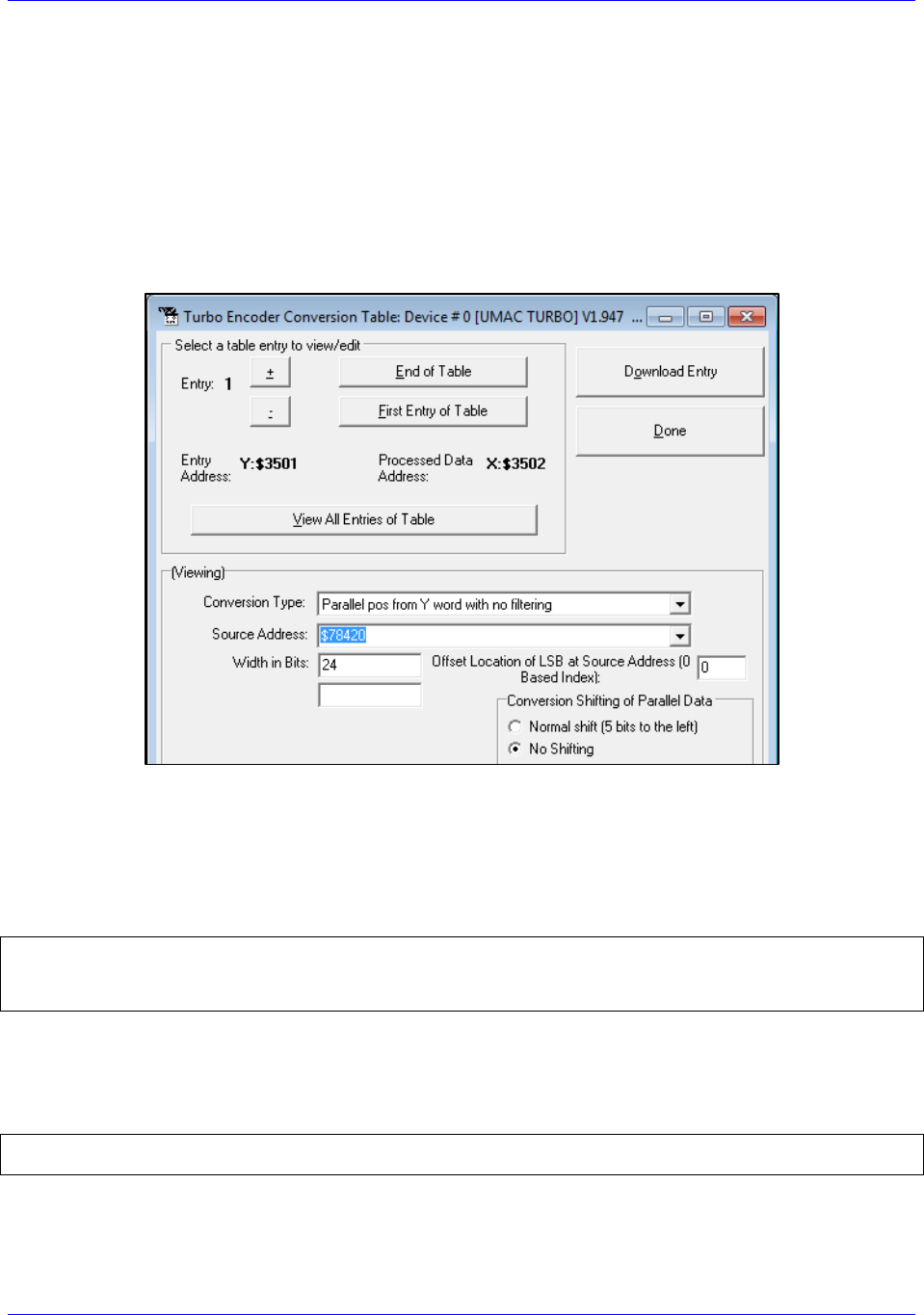
select the address based on the correct nodes enabled for this ACC-24M2A. One can set up the ECT entry
using PeWin32Pro2 by clicking (from within the software) on ConfigureEncoder Conversion Table,
showing this window:
The only field the user needs to change on this screen is the Source Address and the Entry Number. Make
the Source Address the correct address depending on the node to which this ECT entry corresponds.
Make the Entry Number whatever is desired as long as it does not conflict with an ECT entry currently
used for another motor.
Example: Motors 1–2 on Nodes 0 and 1, respectively
I8000=$2F8420 // Unfiltered parallel pos of location Y:$78420, Node 0
I8001=$18000
I8002=$2F8424 // Unfiltered parallel pos of location Y:$78424, Node 1
I8003=$18000
the numerical hex value Processed Data Address listed the
ECT window shown above.
Example: Motors 1–2 Ixx03 and Ixx04 setting:
I103=$3502 I104=$3502
I203=$3503 I204=$3503
The only exception to this would be if the user wants to use dual feedback on ACC-24M2A and is
therefore using both encoder channels for one motor, in which case the user must make one ECT entry for
each encoder and point Ixx03 to the position encoder and Ixx04 to the velocity encoder.

Accessory 24M2A
Configuring with Turbo PMAC 42
Digital A Quad B
The user must configure the Encoder Conversion Table on the ACC-24M2A itself as follows:
Example: ACC-24M2A with two motors, one on Node 0, one on Node 1
// ACC-24M2A ECT Setup for Quadrature Encoders
MS0,MI120=$0C090 ; 1/T Extension of Incremental Encoder Ch1
MS0,MI121=$0C098 ; 1/T Extension of Incremental Encoder Ch2
// ACC-24M2A ECT Output Setup
MS0,MI101=$10 ; Output from 1st line of ECT (MI120)
MS0,MI102=$11 ; Output from 2nd line of ECT (MI121)
If the user wants to change the direction of the encoder feedback, he or she can either:
Swap
Change MS<node>, MI910:
If MI910=3, set it to 7 (clockwise rotation is positive)
If MI910=7, set it to 3 (counterclockwise rotation is positive)
Sinusoidal
The user must configure the Encoder Conversion Table on the ACC-24M2A itself as follows:
Example: ACC-24M2A with two motors, one on Node 0, one on Node 1
// ACC-24M2A ECT Setup for Sinusoidal Encoders
// Channel 1
MS0,MI120=$F0C090 // Data Source Address location
MS0,MI121=$FF00 // A/D Converter Address Setup
MS0,MI122=0 // Sine/Cosine Bias
// Channel 2
MS0,MI123=$F0C098 // Data Source Address location
MS0,MI124=$FF20 // A/D Converter Address Setup
MS0,MI125=0 // Sine/Cosine Bias
// ACC-24M2A ECT Output Setup
MS0,MI101=$12 // Output from 3rd line of ECT (MI122)
MS0,MI102=$15 // Output from 6th line of ECT (MI125)
Note that the third line of the entry for each channel (in this example, MI122 for Channel 1 and MI124 for
Channel 2) contains the bias in the A/D converter values. This line should contain the value that the A/D
converters report when they should ideally report zero. The MACRO Station subtracts this value from
both A/D readings before calculating the arctangent. Many users will leave this value at 0, but it is
particularly useful to remove the offsets of single-ended analog encoder signals. If it appears that the
encoder has an offset, the user can compensate for it in these variables. This line is scaled so that the
maximum A/D converter reading provides the full value of the 24-bit register (+/-223). Generally, it is set
by reading the A/D converter values directly as 24-bit values (in this example, from Y:$C090 for Channel
1 and from Y:$C098 for Channel 2), computing the average value over a cycle or cycles, and entering this
value here.
For more detail on how the Sinusoidal Interpolation works in PMAC, see Appendix D.
Note
At this point of the setup process, you should be able to move the
motor/encoder shaft by hand and see encoder counts in the position
window

Accessory 24M2A
Configuring with Turbo PMAC 43
SSI
ACC-24M2A can be configured to process SSI encoder feedback as a binary parallel word in 12, 16, 20,
or 24-bit format. As with all feedback, this data is transferred across the MACRO ring to be used as
position and/or velocity feedback. Each SSI device requires three lines of the ECT.
In the second line of each SSI ECT entry, the number of bits to process is specified. So, there are four
examples given below.
In the third line, specify the maximum change per servo cycle of the encoder counts that is expected. This
is typically equal to 1.25 times the maximum expected velocity of the motor. The units of this entry
are whatever the units of the input register are, typically 1/32 of a count. For example, to limit the change
in one servo cycle to 64 counts with an input register in units of 1/32 count, this third line would be 64*32
= 2048.
In the examples below, the user must specify the maximum count change per servo cycle on the lines
which end -
Example: ACC-24M2A with two motors, each with a 12-bit SSI encoder, one on Node 0, one on
Node 1
#define MaxVelCh1 0 // Maximum count change per servo cycle, Channel 1 –User Input
#define MaxVelCh2 0 // Maximum count change per servo cycle, Channel 2 –User Input
// ACC-24M2A ECT Setup
//Channel 1
MS0,MI120=$30FF54 // Data Source Address location
MS0,MI121=$000FFF // 12-bit SSI conversion
MS0,MI122=MaxVelCh1*32
//Channel 2
MS0,MI123=$30FF74 // Data Source Address location
MS0,MI124=$000FFF // 12-bit SSI conversion
MS0,MI125=MaxVelCh2*32
// ACC-24M2A ECT output setup
MS0,MI101=$12 // Output from 3rd line of ECT (MI122)
MS0,MI102=$15 // Output from 6th line of ECT (MI125)
Example: ACC-24M2A with two motors, each with a 16-bit SSI encoder, one on Node 0, one on
Node 1
#define MaxVelCh1 0 // Maximum count change per servo cycle, Channel 1 –User Input
#define MaxVelCh2 0 // Maximum count change per servo cycle, Channel 2 –User Input
// ACC-24M2A ECT Setup
//Channel 1
MS0,MI120=$30FF54 // Data Source Address location
MS0,MI121=$00FFFF // 16-bit SSI conversion
MS0,MI122=MaxVelCh1*32
//Channel 2
MS0,MI123=$30FF74 // Data Source Address location
MS0,MI124=$00FFFF // 16-bit SSI conversion
MS0,MI125=MaxVelCh2*32
// ACC-24M2A ECT output setup
MS0,MI101=$12 // Output from 3rd line of ECT (MI122)
MS0,MI102=$15 // Output from 6th line of ECT (MI125)

Accessory 24M2A
Configuring with Turbo PMAC 44
Example: ACC-24M2A with two motors, each with a 20-bit SSI encoder, one on Node 0, one on
Node 1
#define MaxVelCh1 0 // Maximum count change per servo cycle, Channel 1 –User Input
#define MaxVelCh2 0 // Maximum count change per servo cycle, Channel 2 –User Input
// ACC-24M2A ECT Setup
//Channel 1
MS0,MI120= $30FF54 // Data Source Address location
MS0,MI121=$0FFFFF // 20-bit SSI conversion
MS0,MI122=MaxVelCh1*32
//Channel 2
MS0,MI123= $30FF74 // Data Source Address location
MS0,MI124=$0FFFFF // 20-bit SSI conversion
MS0,MI125=MaxVelCh2*32
// ACC-24M2A ECT output setup
MS0,MI101=$12 // Output from 3rd line of ECT (MI122)
MS0,MI102=$15 // Output from 6th line of ECT (MI125)
Example: ACC-24M2A with two motors, each with a 24-bit SSI encoder, one on Node 0, one on
Node 1
#define MaxVelCh1 0 // Maximum count change per servo cycle, Channel 1 –User Input
#define MaxVelCh2 0 // Maximum count change per servo cycle, Channel 2 –User Input
// ACC-24M2A ECT Setup
//Channel 1
MS0,MI120= $30FF54 // Data Source Address location
MS0,MI121=$FFFFFF // 24-bit SSI conversion
MS0,MI122=MaxVelCh1*32
//Channel 2
MS0,MI123= $30FF74 // Data Source Address location
MS0,MI124=$FFFFFF // 24-bit SSI conversion
MS0,MI125=MaxVelCh2*32
// ACC-24M2A ECT output setup
MS0,MI101=$12 // Output from 3rd line of ECT (MI122)
MS0,MI102=$15 // Output from 6th line of ECT (MI125)
Note
If the direction decode variable, MS<node>, MI910, is changed the
user must save the setting, MSSAVE{node} and reset the card
MS$$${node} before the fractional direction sense matches.
Note
At this point of the setup process, you should be able to move the
motor/encoder shaft by hand and see encoder counts in the position
window

Accessory 24M2A
Configuring with Turbo PMAC 45
Resolver
ECT Setup
ACC-24M2A has up to two channels of resolver inputs. The inputs may be used as feedback or master
reference signals for the PMAC servo loops. The basic configuration of the drive contains one 10-bit fixed
resolution tracking resolver-to-digital (R-to-D) converters, with an optional second resolver when a dual
axis driver is ordered. ACC-24M2A creates the AC excitation signal (ResOut) for up to two resolvers,
accepts the modulated sine and cosine signals back from these resolvers, demodulates the signals and
derives the position of the resolver from the resulting information, in an absolute sense if necessary.
The specifics for this configuration are as follows (Ch1 and Ch2):
Example: ACC-24M2A with two motors, each with a resolver, one on Node 0, one on Node 1,
wherein the clockwise direction of the motor’s shaft’s rotation is positive
// ACC-24M2A ECT Setup
// Channel 1
MS0,MI120=$E0FF00 // Data Source Address location ,CW
MS0,MI121=$00FF5C // A/D Converter Address Setup
MS0,MI122=0 // Sine/Cosine Bias –User Input
// Channel 2 CW
MS0,MI123=$E0FF20 // Data Source Address location, CW
MS0,MI124=$00FF5C // A/D Converter Address Setup
MS0,MI125=0 // Sine/Cosine Bias –User Input
// ACC-24M2A ECT Output Setup
MS0,MI101=$12 // Output from 3rd line of ECT (MI122)
MS0,MI102=$15 // Output from 6th line of ECT (MI125)
Example: ACC-24M2A with two motors, each with a resolver, one on Node 0, one on Node 1,
wherein the counterclockwise direction of the motor’s shaft’s rotation is positive
// ACC-24M2A ECT Setup
// Channel 1
MS0,MI120=$E8FF00 // Data Source Address location ,CCW
MS0,MI121=$00FF5C // A/D Converter Address Setup
MS0,MI122=0 // Sine/Cosine Bias –User Input
// Channel 2 CW
MS0,MI123=$E8FF20 // Data Source Address location, CCW
MS0,MI124=$00FF5C // A/D Converter Address Setup
MS0,MI125=0 // Sine/Cosine Bias –User Input
// ACC-24M2A ECT Output Setup
MS0,MI101=$12 // Output from 3rd line of ECT (MI122)
MS0,MI102=$15 // Output from 6th line of ECT (MI125)
Note that the third line of the entry for each channel (in this example, MI122 for Channel 1 and MI124 for
Channel 2) contains the bias in the A/D converter values. This line should contain the value that the A/D
converters report when they should ideally report zero. The MACRO Station subtracts this value from
both A/D readings before calculating the arctangent. Many users will leave this value at 0, but it is
particularly useful to remove the offsets of single-ended analog encoder signals. If it appears that the
encoder has an offset, the user can compensate for it in these variables. This line is scaled so that the
maximum A/D converter reading provides the full value of the 24-bit register (+/-223). Generally, it is set
by reading the A/D converter values directly as 24-bit values (in this example, from Y:$C090 for Channel
1 and from Y:$C098 for Channel 2), computing the average value over a cycle or cycles, and entering this
value here.

Accessory 24M2A
Configuring with Turbo PMAC 46
Note
If the direction decode variable, MS<node>, MI910, is changed the
user must save the setting, MSSAVE{node} and reset the card
MS$$${node} before the fractional direction sense matches.
Configuring Excitation Frequency
After setting up the ECT, the user then must set three MI-Variables for the Resolvers to function
correctly.
The ResOut signal (i.e. the Resolver excitation frequency) emitted from the ACC-24M2A is derived
from the Phase Clock frequency of the MACRO set by MI992 and MI997. The user has the ability to
select the excitation frequency to be equal with the Phase Clock frequency (default) by setting
MS<node>,MI982 equal to 0. Or, the user can use lower frequencies by increasing the value of MI982.
MI982 affects the excitation frequency as follows:
MI982 Setting
Excitation Frequency
MI982=1
(Phase Clock Frequency)/2
MI982=2
(Phase Clock Frequency)/4
MI982=3
(Phase Clock Frequency)/6

Accessory 24M2A
Configuring with Turbo PMAC 47
Configuring the Excitation Signal’s Gain
Additionally, the user needs to set the Excitation output gain for the systems resolvers by setting
MS<node>,MI981.
MI981 Setting
Excitation Signal Gain
MI981=0
2.5 Vpp
MI981=1
5.0 Vpp
MI981=2
7.5 Vpp
MI981=3
10.0 Vpp
Configuring the Excitation Signal’s Phase Offset
Finally the resolver excitation phase time offset, MS<node>, MI980, needs to be set. The optimum
setting of MI980 depends on the L/R time constant of the resolver circuit. Therefore, MI980 should be set
interactively to maximize the magnitudes of the feedback ADC values.
For each channel, there are two ADC registers which hold the sin and cosine values. For Channel 1, the
base/first ADC register address is Y:$FF00 and the second ADC register address is Y:$FF01; For
Channel 2, the base/first ADC register address is Y:$FF20 and the second ADC register address is
Y:$FF21. There is no MI-Variable to directly address these registers, so MI198 (Direct Read/Write Format
and Address) and MI199 (Direct Read/Write Variable) will be used here. For each channel, both ADCs
should be observed during setup. Notice that MI199 can only be pointed to one register at one time so it
must be configured twice throughout the following procedure.
Procedure for Configuring MI980 on Channel 1
The procedure for configuring MI980 for Channel 1 is as follows:
1. In PeWin32Pro2, open a Watch Window (ViewWatch Window).
2. MS<node>,MI199, where <node> is the node number of this ACC-
24M2As motor (e.g. if this motor is on Node 0, type MS0,MI199).
3. In the Terminal Window (ViewTerminal), type MS<node>,MI198=$6DFF00, where <node>
4. Rotate the motor on this channel. Observe MS<node>,MI199 in the Watch Window. If it
saturates to ±32767, the resolver gain (MI981) is too high. Decrease MI981 until the MI199 just
barely saturates to ±32767. If it does not saturate, type MS<node>,MI198=$6DFF01 in the
Terminal Window ) and then repeat step 4.
5. Set MI199 to point to the ADC which saturated; that is, if ADC1 saturated, type
MS<node>,MI198=$6DFF00 in the Terminal Window, or if ADC2 saturated, type
MS<node>,MI198=$6DFF01 in the Terminal Window.
6. the ADC value is close to the maximum value observed
. At this point, the other ADC should be close to 0.
7. Increase MI980 by increments of 25. The ADC value should start to increase slowly. If it
decreases, instead start with MI980=255 and then decrease MI980 by increments of 25. The ADC
value should increase up to a maximum point and then start to decrease again. Set MI980 to the
value that produced the largest absolute ADC value achieved throughout the process of adjusting
MI980.
8. If the maximum absolute value of this ADC is less than 16,000, increase the gain of the resolver
by increasing MI981.

Accessory 24M2A
Configuring with Turbo PMAC 48
Procedure for Configuring MI980 on Channel 2
The procedure for configuring MI980 for Channel 2 is as follows:
1. In PeWin32Pro2, open a Watch Window (ViewWatch Window).
2. MS<node>,MI199, where <node> is the node number of this ACC-
MS0,MI199).
3. In the Terminal Window (ViewTerminal), type MS<node>,MI198=$6DFF20, where <node>
4. Rotate the motor on this channel. Observe MS<node>,MI199 in the Watch Window. If it
saturates to ±32767, the resolver gain (MI981) is too high. Decrease MI981 until the MI199 just
barely saturates to ±32767. If it does not saturate, type MS<node>,MI198=$6DFF21 in the
5. Set MI199 to point to the ADC which saturated; that is, if ADC1 saturated, type
MS<node>,MI198=$6DFF20 in the Terminal Window, or if ADC2 saturated, type
MS<node>,MI198=$6DFF21 in the Terminal Window.
6.
7. Increase MI980 by increments of 25. The ADC value should start to increase slowly. If it
decreases, instead start with MI980=255 and then decrease MI980 by increments of 25. The ADC
value should increase up to a maximum point and then start to decrease again. Set MI980 to the
value that produced the largest absolute ADC value achieved throughout the process of adjusting
MI980.
8. If the maximum absolute value of this ADC is less than 16,000, increase the gain of the resolver
by increasing MI981.
Note
At this point of the setup process, you should be able to move the
motor/encoder shaft by hand and see encoder counts in the position
window
Accessory 24M2A
Configuring with Turbo PMAC 49
Flags
On the Ring Controller, the flags (Ixx25) must point to the servo node used for the
motors on ACC-24M2A.
Example: Motors 1–2 on Nodes 0 and 1, respectively
I125=$3440
I225=$3441
Note
These examples configure only motors 12. If you are configuring
other motors, refer to the Turbo PMAC Software Reference Manual
for a list of the addresses for Ixx25.
Then, on the Ring Controller, the flag control (Ixx24) variable must be set up for each motor on ACC-
24M2A as follows:
Ixx24 Setting
Description
$40001
Overtravel limits enabled
$60001
Overtravel limits disabled
Example: Flag Control for Motors 1–2
I124,2,100=$40001 // Motor 1–2 have overtravel limits enabled
Output Commands
On the Ring Controller, the output command address must be set to the ACC-
node addresses directly.
Example: Motors 1–2 on Nodes 0 and 1, respectively
I102=$078420 // Motor 1’s output command address is Node 0
I202=$078424 // Motor 2’s output command address is Node 1
Note
These examples configure only motors 12. If you are configuring
other motors, refer to the Turbo PMAC Software Reference Manual
table for a list of the addresses for Ixx02.

Accessory 24M2A
Configuring with Turbo PMAC 50
I2T Settings
The I2T overcurrent protection should be configured for each motor on ACC-24M2A. Below is an
example with some formulas for setting up I2T-
Example: Configuring I2T Protection for Motors 1–2
I15=0 ; Trigonometric calculation in degrees
#define MaxPhaseFreq P7000 ; Max Phase Clock [KHz]
#define PWMClk P7001 ; PWM Clock [KHz]
#define PhaseClk P7002 ; Phase Clock [KHz]
#define ServoClk P7003 ; Servo Clock [KHz]
MaxPhaseFreq=117964.8/(2*I6800+3)
PWMClk=117964.8/(4*I6800+6)
PhaseClk=MaxPhaseFreq/(I6801+1)
ServoClk=PhaseClk/(I6802+1)
#define Axis1MinContCurrent 3 ; Continuous Current Limit for Axis 1 [Amps] –User Input
#define Axis1MinPeakCurrent 9 ; Instantaneous Current Limit for Axis 1 [Amps] –User Input
#define Axis1AmpPeakInstCurrent 16.3 ; Peak Instant. Current of Amplifier [Amps] –User Input
#define Axis1I2TOnTime 2 ; Time allowed at peak Current [sec]
// Assuming that motor 1 is the first motor on MACRO
I157=INT(32767*(Axis1MinContCurrent/Axis1AmpPeakInstCurrent)
I169=INT(32767*(Axis1MinPeakCurrent/Axis1AmpPeakInstCurrent)
I158=INT((I169*I169-I157*I157)*ServoClk*1000*Axis1I2TOnTime/(32767*32767))
I257=I157 I269=I169 I258=I158 // Assumes motor 2 is the same as motor 1
The continuous current limit (Axis1MinContCurrent) and the instantaneous current limit
(Axis1MinPeakCurrent) -
smaller of the two limits between your motor and y
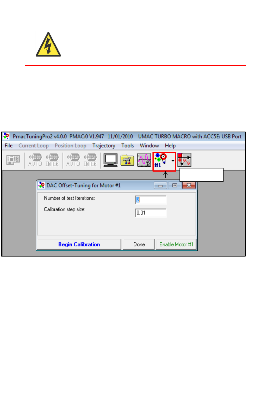
Accessory 24M2A
Configuring with Turbo PMAC 51
DAC Calibration
WARNING
Before performing the DAC Calibration, make sure there is no
load attached to the motor, and make sure that the motor can
safely and freely move. This step of the setup can generate much
motion in the motor.
At this stage in the setup, the user should calibrate the DACs on ACC-24M2A to make sure that when he
or she commands 0 volts on the DACs, they actually put out 0 volts. To do this, open PMAC Tuning Pro2
by clicking on ToolsPMAC Tuning Pro2 from within PeWin32Pro2. Then, click Position LoopDAC
Calibration. Make sure there is no load presently connected to the motor. Then,
PMAC will automatically calibrate your DAC. Once it is done, accept the change it makes to Ixx29. You
may want to write down this value to add to your setup file. Do this test for both motors (you can select
another motor with the Motor Select button):
Motor Select
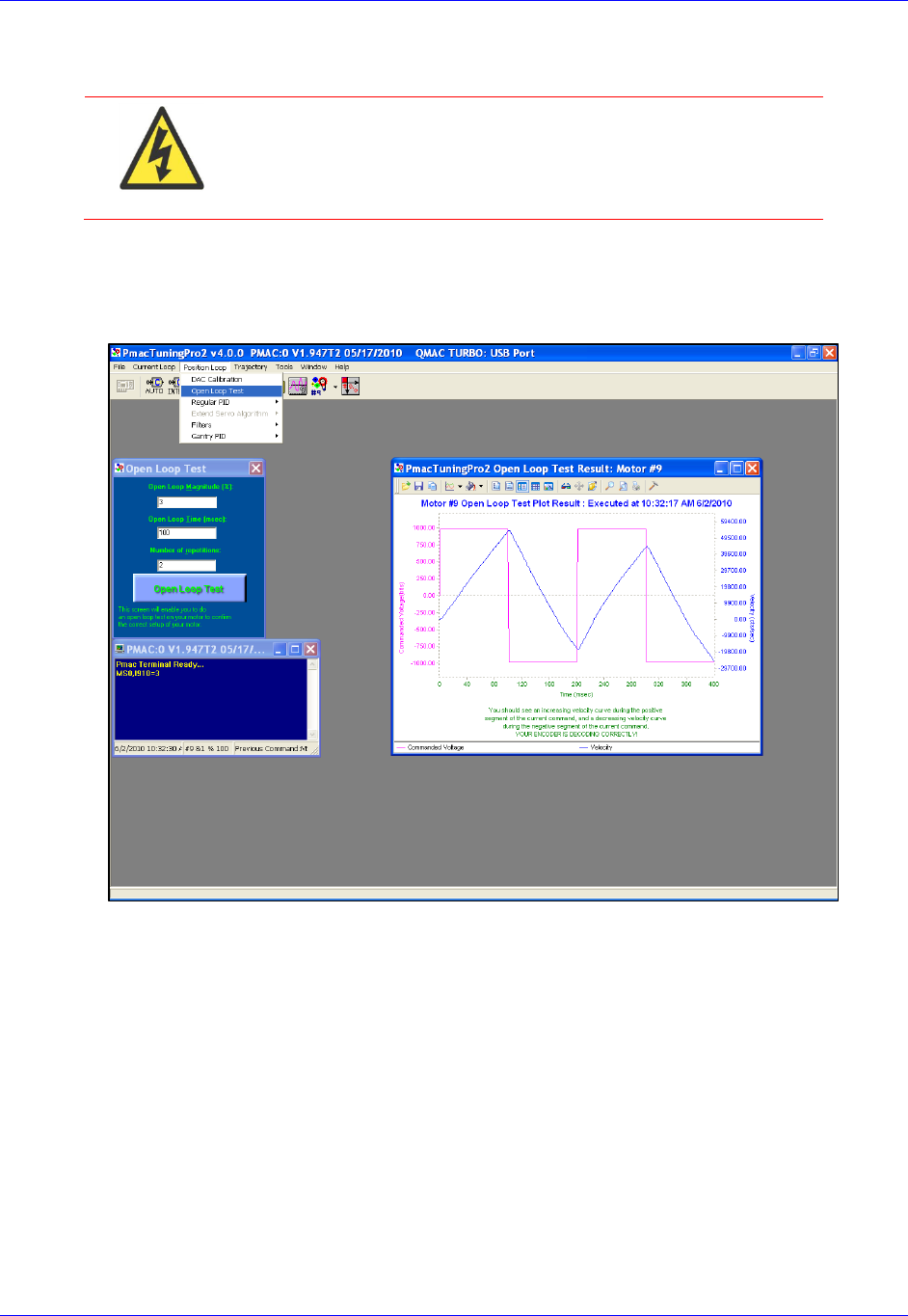
Accessory 24M2A
Configuring with Turbo PMAC 52
Open Loop Test
WARNING
Before performing the Open Loop Test, make sure there is no
load attached to the motor, and make sure that the motor can
safely and freely move. This step of the setup can generate much
motion in the motor.
The user should now execute an Open-Loop test in order to determine whether the feedback from ACC-
24M2A is working properly. To do this, open PMAC Tuning Pro2 from PeWin32Pro2 by clicking on
ToolsPMAC Tuning Pro2. Then, click Position LoopOpen Loop Test.
You should see the actual velocity increasing positively while the commanded velocity is positive, the
actual velocity decreasing while the commanded velocity is negative.
If you see an erratic response, or an inverted saw tooth, then most likely the encoder decode setting is
incorrect. This is on the MACRO side, MS{node},MI910 has to be changed from 7 to 3, or vice versa.

Accessory 24M2A
Configuring with Turbo PMAC 53
Servo Loop Tuning
amplifiers. Configuration is done by adjusting I-Variables (Ixx30 through Ixx35) pertaining to the PID
gains. Ixx68 (Friction Feedforward) is also needed. The servo loop gains correspond to I-Variables as
follows:
Ixx30 Proportional Gain (Kp)
Ixx31 Derivative Gain (Kd)
Ixx32 Velocity Feedforward (Kvff)
Ixx33 Integral Gain (Ki)
Ixx34 Integration Mode
Ixx35 Acceleration Feedforward (Kaff)
Ixx68 Friction Feedforward (Kfff)
Note
The user should connect the load to the motor before tuning the servo
loop.
. The procedure for tuning is as
follows:
1. Set Ixx34 (Motor xx PID Integration Mode) can be changed on the fly as needed
=1, position error integration is performed only when Motor xx is not commanding a move
=0, position error integration is performed always
2. Using the Step Response, tune the following parameters in this order:
Proportional Gain, Kp (Ixx30)
Derivative Gain, Kd (Ixx31)
Integral Gain, Ki (Ixx33)
3. Using the Parabolic Move, tune the following parameters in this order:
Velocity Feedforward, Kvff (Ixx32)
Acceleration Feedforward, Kaff (Ixx35)
Friction Feedforward, Kfff (Ixx68)
Note
When tuning the feedforward gains, set Ixx34=1 so that the
dynamic behavior of the system may be observed without
integrator action. After tuning these, set Ixx34 back to your
desired setting.
Setting Kvff = Kd (Ixx32 = Ixx31) is a good place to start
when tuning Kvff.
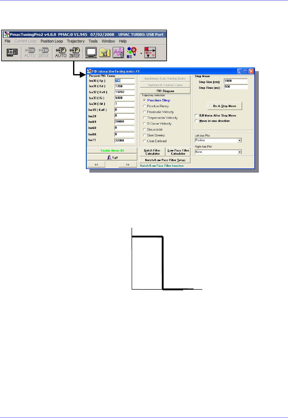
Accessory 24M2A
Configuring with Turbo PMAC 54
Steps 2 and 3 should be performed in the Interactive Tuning window in PMAC Tuning Pro2:
Step 2 (tuning Kp, Kd, and Ki)
S that is
within ½ to ¼ of a revolution of the motor if it is a rotary motor, or within ½ to ¼ of one electrical cycle if
it is a linear motor. The step move should look somewhat like this:
position looks, adjust the servo loop gains until you achieve the desired response.
Interactive Tuning
for Position
Time [sec]
Commanded
Position [cts]
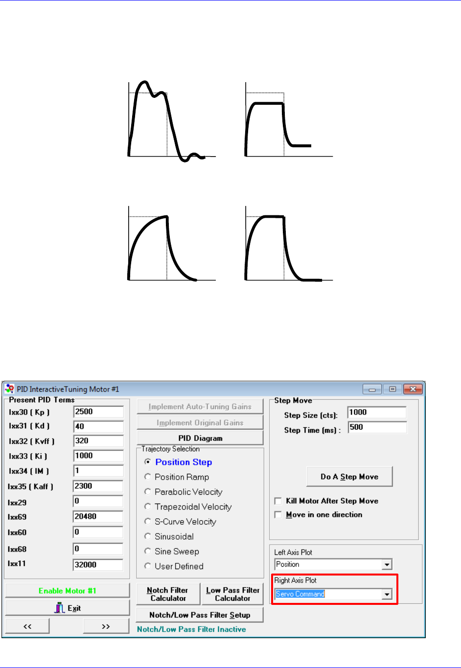
Accessory 24M2A
Configuring with Turbo PMAC 55
Observing the table below, match your actual position response to one of the response shapes below, and
then adjust the appropriate gain as listed next to each plot:
Overshoot and
Oscillation
Cause:
Too much Proportional
gain or
too little Damping
Fix:
Decrease Kp (Ixx30)
Increase Kd (Ixx31)
Position Offset
Cause:
Friction or Constant
Force
Fix:
Increase Ki (Ixx33)
Increase Kp (Ixx30)
Sluggish Response
Cause:
Too much Damping or
too little Proportional
gain
Fix:
Increase Kp (Ixx30) or
Decrease Kd (Ixx31)
Physical System
Limitation
Cause:
Limit of the
Motor/Amplifier/Load
and gain combination
Fix:
Evaluate Performance
and
maybe add Kp (Ixx30)
Typically, one should start by increasing Kp
d and Ki until the performance goals for the step response
are achieved. Be sure when executing the step response that you plot the Servo Command on the Right
Axis:
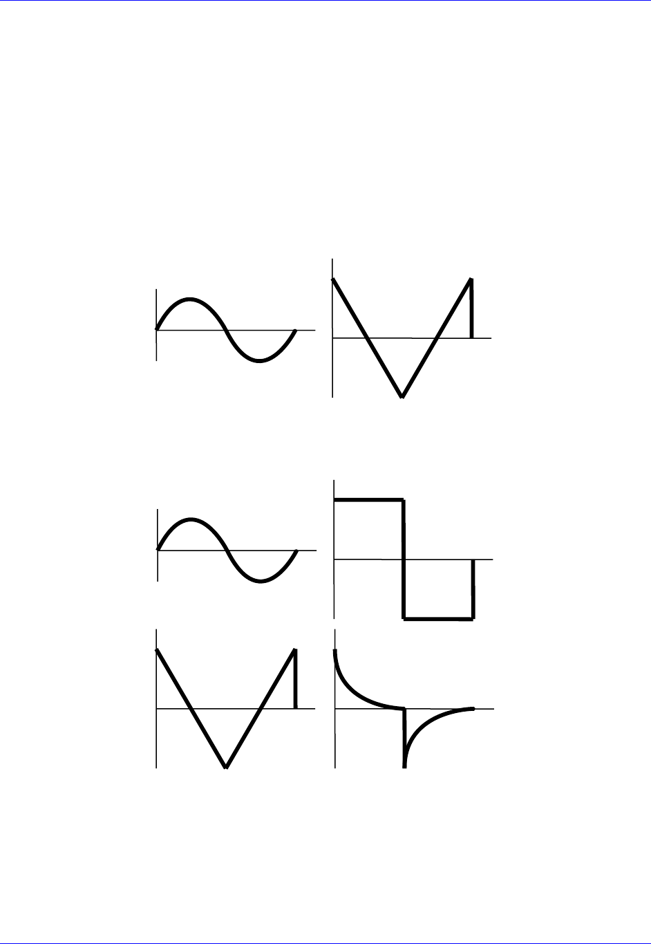
Accessory 24M2A
Configuring with Turbo PMAC 56
If you see a truncation of the servo command at the beginning of each move, you have reached the
maximum output command as determined by Ixx69. In this case, adding more Kp will not improve the
Step 3 (Tuning Kvff, Kaff, and Kfff)
S Select a
move size and speed that will simulate the fastest, harshest moving conditions you expect your machine
to experience. Tune the motor at these settings, and then the motor should be able to handle all easier
moves.
After commanding the Parabolic Velocity move, the commanded Velocity Profile and Acceleration
Profile should look like this:
Velocity
Commanded
Profile
Acceleration
Commanded
Profile
Observing the table below, match your following error response to one of the response shapes below, and
then adjust the appropriate gain as listed next to each plot:
High Vel./F.E.
Correlation
Cause: Damping
Fix: Increase Kvff
(Ixx32)
High Vel./F.E.
Correlation
Cause: Friction
Fix:
Add Friction
Feedforward (Ixx68)
and/or turn on Integral
Gain
(Ixx33, Ixx34)
High Acc./F.E.
Correlation
Cause: Inertial Lag
Fix:
Increase Kaff (Ixx35)
High Acc./F.E.
Correlation
Cause:
Physical System
Limitation
Fix:
Use softer acceleration
or add more Ixx68

Accessory 24M2A
Configuring with Turbo PMAC 57
Negative Vel./F.E.
Correlation
Cause:
Too much Velocity
Feedforward
Fix:
Decrease Kvff
(Ixx32)
High Vel./F.E.
Correlation
Cause: Damping &
Friction
Fix:
Increase Kvff first
(Ixx32)
Possibly adjust
Ixx68
Negative Acc./F.E.
Correlation
Cause:
Too much acceleration
Feedforward
Fix:
Decrease Kaff (Ixx35)
High Vel./F.E. &
Acc./F.E.
Correlation
Cause:
Inertial Lag &
Friction
Fix:
Increase Kaff (Ixx35)
Possibly adjust Ixx68
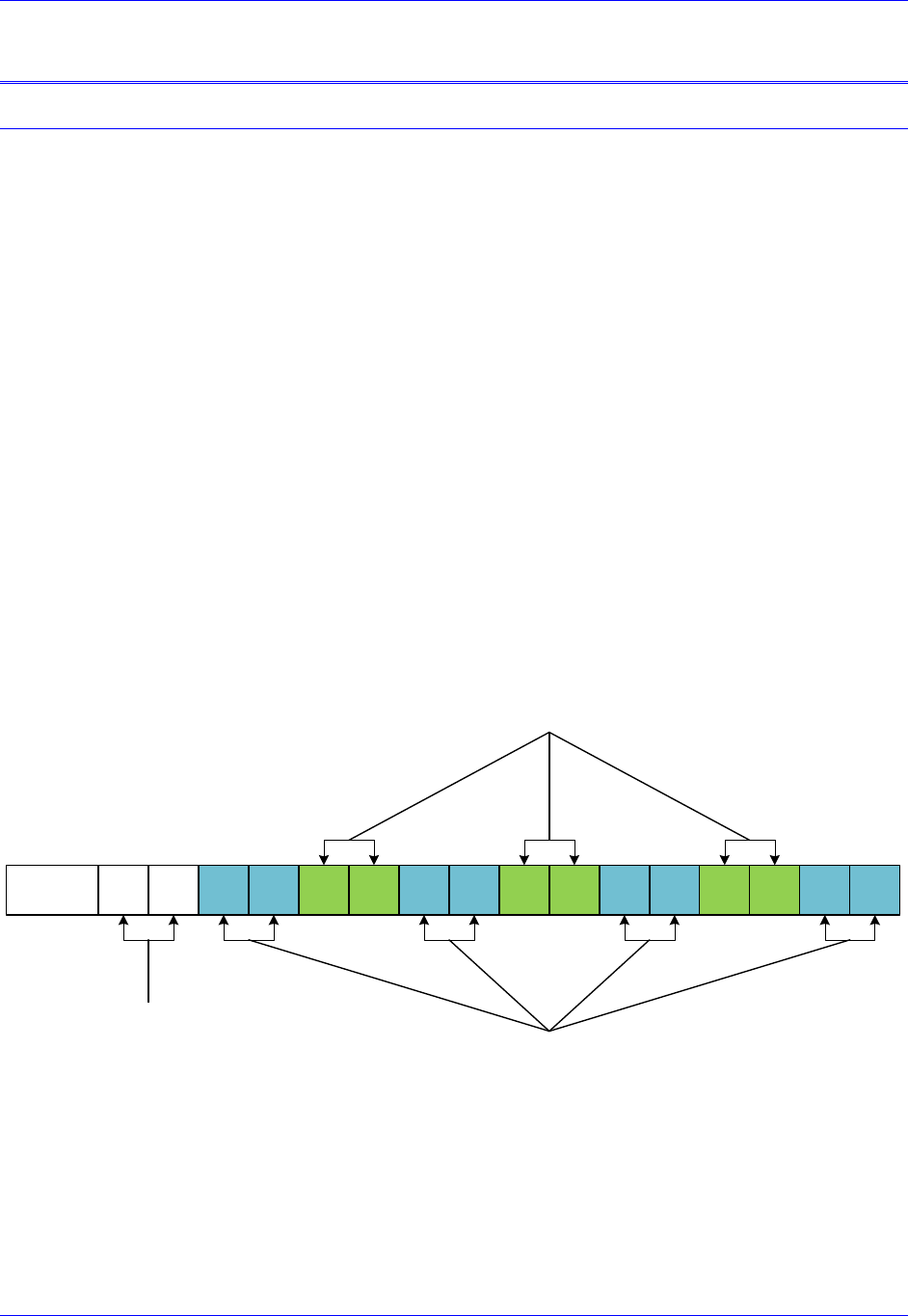
Accessory 24M2A
Configuring with Power PMAC 58
CONFIGURING WITH POWER PMAC
Quick Review: Nodes and Addressing
Two different types of MACRO interfaces are available for Power PMAC: Gate2-style and Gate3-style.
Gate3-
the date this manual was written, ACC-5E3 is the only Gate3-style MACRO interface for Power PMAC.
Gate2-style MACRO interfaces have up to two ICs, each possessing its own registers for MACRO
settings. As of the date this manual was written, ACC-5E is the only Gate2-style MACRO interface for
Power PMAC.
Each MACRO IC (for Gate2-style MACRO interfaces) or each MACRO bank (Bank A and Bank B, for
Gate3-style MACRO interfaces) consists of 16 nodes: 2 auxiliary, 8 servo, and 6 I/O nodes:
Auxiliary nodes are Master/Control registers and are for internal firmware use.
Servo nodes carry information such as feedback, commands, and flags for motor
control.
I/O nodes are by default unoccupied and are user configurable for transferring
miscellaneous data.
Each motor that the ring controller controls requires one servo node, and therefore one ACC-5E3 or
ACC-5E can control a maximum of 16 motors. The number of I/O nodes used depends on what I/O
devices ACC-5E3 or ACC-5E
individual functionality is given below:
15 14 13 12 11 10 9 8 7 6 5 4 3 2 1 0Node
Auxiliary
Nodes
I/O Nodes
Servo Nodes
With Gate3-style MACRO, each node consists of 8 registers: four 32-
accessed by the structure Gate3[i].MacroInA[j][k] for bank A and Gate3[i].MacroInB[j][k] for bank B,
and four 32-
Gate3[i].MacroOutA[j][k] for bank A and Gate3[i].MacroOutB[j][k] for bank B. Gate2-style MACRO
interfaces has 4 registers for each node, wherein the input and output data share the registers; they are all
grouped into this structure: Gate2[i].Macro[j][k].

Accessory 24M2A
Configuring with Power PMAC 59
Data Organization within Servo Nodes
When controlling non-Gate3 MACRO Stations, each MACRO interface will have its servo node
information split up differently within each node j depending on the commutation method being used.
The three modes involved are:
Analog Output Mode
Motor[x].PhaseCtrl = 0
Motor[x].pAdc = 0
UV Commutation Mode (a.k.a. Sinusoidal Commutation Mode)
Motor[x].PhaseCtrl > 0
Motor[x].pAdc = 0
Direct PWM Mode
Motor[x].PhaseCtrl > 0
Motor[x].pAdc > 0 (=Gate3[i].MacroInA[j][1] for MACRO motors on Gate3-style MACRO,
=Gate2[i].Macro[j][1] for Gate2-style)
In Gate3-style MACRO, the contents of each servo node are arranged in each MACRO bank as follows:
Gate3[i].MacroInA[j][0] 24 bits of feedback information 8 bits of 0
Gate3[i].MacroInA[j][1]
Gate3[i].MacroInA[j][2]
Gate3[i].MacroInA[j][3]
Not Used in Analog Output Mode/
Not Used in UV Commutation Mode/
16 bits of current sensor ADCA in Direct PWM Mode
16 bits of 0
Not Used in Analog Output Mode/
Not Used in UV Commutation Mode/
16 bits of current sensor ADCB in Direct PWM Mode
16 bits of 0
16 bits of channel status/flag information 16 bits of 0
Gate3[i].MacroOutA[j][0]
24 bits of servo output command in Analog Output Mode/
24 bits of DACA output in UV Commutation Mode/
24 bits of PWMA command in Direct PWM Mode
8 bits of 0
Gate3[i].MacroOutA[j][1]
Gate3[i].MacroOutA[j][2]
Gate3[i].MacroOutA[j][3]
Not Used in Analog Output Mode/
16 bits of DACB command in UV Commutation Mode/
16 bits of PWMB command in Direct PWM Mode
16 bits of 0
Not Used in Analog Output Mode/
Not Used in UV Commutation Mode/
16 bits of PWMC command in Direct PWM Mode
16 bits of 0
16 bits of channel control commands/flag commands 16 bits of 0
Gate3-Style MACRO Bank A Register Structure
Node Structure Bit 31 Bit 0

Accessory 24M2A
Configuring with Power PMAC 60
Gate3[i].MacroInB[j][0] 24 bits of feedback information 8 bits of 0
Gate3[i].MacroInB[j][1]
Gate3[i].MacroInB[j][2]
Gate3[i].MacroInB[j][3]
Not Used in Analog Output Mode/
Not Used in UV Commutation Mode/
16 bits of current sensor ADCA in Direct PWM Mode
16 bits of 0
Not Used in Analog Output Mode/
Not Used in UV Commutation Mode/
16 bits of current sensor ADCB in Direct PWM Mode
16 bits of 0
16 bits of channel status/flag information 16 bits of 0
Gate3[i].MacroOutB[j][0]
24 bits of servo output command in Analog Output Mode/
24 bits of DACA output in UV Commutation Mode/
24 bits of PWMA command in Direct PWM Mode
8 bits of 0
Gate3[i].MacroOutB[j][1]
Gate3[i].MacroOutB[j][2]
Gate3[i].MacroOutB[j][3]
Not Used in Analog Output Mode/
16 bits of DACB command in UV Commutation Mode/
16 bits of PWMB command in Direct PWM Mode
16 bits of 0
Not Used in Analog Output Mode/
Not Used in UV Commutation Mode/
16 bits of PWMC command in Direct PWM Mode
16 bits of 0
16 bits of channel control commands/flag commands 16 bits of 0
Gate3-Style MACRO Bank B Register Structure
Node Structure Bit 31 Bit 0

Accessory 24M2A
Configuring with Power PMAC 61
In Gate2-style MACRO, the contents of each servo node are arranged in each MACRO IC as follows:
Gate2[i].Macro[j][0] 24 bits of feedback information
Gate2[i].Macro[j][1]
Gate2[i].Macro[j][2]
Gate2[i].Macro[j][3]
Not Used in Analog Output Mode/
Not Used in UV Commutation Mode/
16 bits of current sensor ADCA in Direct PWM Mode
8 bits of 0
Not Used in Analog Output Mode/
Not Used in UV Commutation Mode/
16 bits of current sensor ADCB in Direct PWM Mode
8 bits of 0
16 bits of channel status/flag information 8 bits of 0
Gate2[i].Macro[j][0]
24 bits of servo output command in Analog Output Mode/
24 bits of DACA output in UV Commutation Mode/
24 bits of PWMA command in Direct PWM Mode
Gate2[i].Macro[j][1]
Gate2[i].Macro[j][2]
Gate2[i].Macro[j][3]
Not Used in Analog Output Mode/
16 bits of DACB command in UV Commutation Mode/
16 bits of PWMB command in Direct PWM Mode
8 bits of 0
Not Used in Analog Output Mode/
Not Used in UV Commutation Mode/
16 bits of PWMC command in Direct PWM Mode
8 bits of 0
16 bits of channel control commands/flag commands 8 bits of 0
Gate2-Style MACRO Input Register Structure
Node Structure Bit 23 Bit 0
Gate2-Style MACRO Output Register Structure
Node Structure Bit 23 Bit 0
Since no Gate3-style MACRO Station products have yet been developed, this is the only node
arrangement available until future developments.
Note
I/O Nodes can be arranged in any way desired, and as such, this
manual does not have any section describing any specific data
arrangement structure within I/O nodes.

Accessory 24M2A
Configuring with Power PMAC 62
Setup Overview
This setup assumes that:
The Ring Master has already been properly configured to run its own local motors.
The user is familiar with enabling servo nodes on both the MACRO Ring Controller and Slave
Station.
In order to set up ACC-24M2A with Power PMAC, the user must:
1. On the Ring Master, enable one (if ACC-24M2A will only use one motor) to two (using two
motors) servo nodes (any two unused servo nodes) per ACC-24M2A.
Structures involved for Gate3-Style MACRO Interfaces:
Gate3[i].MacroEnableA MACRO IC Bank A Node Activate Control
Gate3[i].MacroEnableB MACRO IC Bank A Node Activate Control
Gate3[i].MacroModeA MACRO IC Bank A Status and Control
Gate3[i].MacroModeB MACRO IC Bank B Status and Control
Structures involved for Gate2-Style MACRO Interfaces:
Gate2[i].MacroEnable MACRO IC Node Activate Control
Gate2[i].MacroMode MACRO IC Ring Configuration/Status
Also, make sure Macro.TestPeriod, Macro.TestMaxErrors, and Macro.TestReqdSynchs
have been properly configured on the Master.
2. Establish communication between the Master and the ACC-24M2A using MACRO ASCII Mode
and enable one or two servo nodes on ACC-24M2A corresponding to the nodes activated on the
Master.
Variables involved:
MacroSlave{anynode},MI11 MACRO Station Station Number
MacroSlave{anynode},MI995 MACRO Ring Configuration/Status
MacroSlave{anynode},MI996 MACRO Node Activate Control
3. Set up Feedback.
4. Set up Flag and Output Command Registers.
5. Configure I2T Protection.
6. Perform an Open Loop Test.
7. Tune the Servo Loop.

Accessory 24M2A
Configuring with Power PMAC 63
Setup Step 1: MACRO Connectivity
ACC-24M2A requires that the same number of servo nodes be activated on the Power PMAC as there are
motors being used on ACC-24M2A; e.g. two servo nodes should be enabled on the Ring Controller if
using two motors, one servo node if using only one motor. Power PMAC MACRO has three variables for
error checking that must also be configured:
Macro.TestPeriod
This is the period in milliseconds at which PMAC checks for errors on the MACRO ring. The
recommended value for this variable is 20.
Macro.TestMaxErrors
This is the maximum error count PMAC can receive in one test period (whose duration is specified by
Macro.TestPeriod) before triggering a fault. The formula for computing this variable is as follows:
.
Macro.TestReqdSynchs
This is the number of sync packets in one period (whose duration is specified by Macro.TestPeriod) that
PMAC must receive before triggering an error. The formula for computing this variable is as follows:
-.
Example MACRO Communication Setup
Configuring a Gate3-Style MACRO interface to enable 16 servo nodes and 12 I/O nodes on a Power
PMAC, which is acting as a Ring Controller.
Sys.WpKey=$AAAAAAAA;
// MACRO Communication Setup
Gate3[0].MacroEnableA=$0FFFFF00; // Activate 8 Servo Nodes and 6 I/O Nodes of MACRO A
Gate3[0].MacroModeA=$403000; // Set MACRO A as master
Gate3[0].MacroEnableB=$1FFFFF00; // Activate 8 Servo Nodes and 6 I/O Nodes of MACRO B
Gate3[0].MacroModeB=$9000; // Set MACRO B as master to synchronize clock
Macro.TestPeriod=20; // MACRO Ring Check Period [msec]
Macro.TestMaxErrors=Macro.TestPeriod/10; // MACRO Maximum Ring Error Count
Macro.TestReqdSynchs=Macro.TestPeriod - Macro.TestMaxErrors; // MACRO Minimum Sync Packet Count

Accessory 24M2A
Configuring with Power PMAC 64
Setup Step 2: Communicating with ACC-24M2A over MACRO ASCII
ACC-24M2A has no rotary switches to determine its MACRO Station Number. Therefore, ACC-24M2A
uses the Ring Order method to obtain its Station Number. Before the ACC-24M2A has been initialized, it
will by default be at MACRO Station #255.
If ACC-24M2A is not at factory default, the user can reinitialize it as follows:
If using MACRO IC #0, to reinitialize ACC-24M2A, type MacroSlave$$$***15, then
MacroSlaveSAVE15, then MacroSlave$$$15.
If using MACRO IC #1, type MacroSlave$$$***31, then MacroSlaveSAVE31, then
MacroSlave$$$31.
If using MACRO IC #2, use MacroSlave$$$***47, then MacroSlaveSAV47, then
MacroSlave$$$47, and so on for other MACRO IC #s.
Then, establishing communication is as follows:
1. Within the Power PMAC IDE, in the Terminal Window, type MacroStation255.
2. Type I11=n in order to assign this ACC-24M2A to Station #n.
Note
ACC-24M2A must be assigned to any unused Station Number (e.g.
I11=1 to assign ACC-24M2A to Station #1).
If a Macro I/O error is received, make sure communication settings
are set correctly. Also make sure that the ACC-24M2A has not been assigned a Station number
already. If the Station has already been assigned a Station number, there are two options:
A. Find out the station number n and enter MacroStation<n> (without the angular
brackets), where n is the station number, to initiate MACRO ASCII communication with
the Station.
C. Reset the station number of all the Stations by entering MacroStation0 and then enter
I11=0.
3. Type <MacroStationClose to exit MACRO ASCII Mode.
4. Type MacroStation<n> (without the angular brackets), where n is the Station Number assigned
in step 2 (e.g. MacroStation1 to open ASCII communication with Station #1).
5. Assign the node and master number on the ACC-24M2A with MI996.
For example, to assign the Station to Nodes 0 and 1 on Master IC #0 on the ACC-24M2A, type:
MI996=$FC003
6. Set MI995=$80.
Example:
MI995=$80
7. Type <MacroStationClose to exit MACRO ASCII Mode.

Accessory 24M2A
Configuring with Power PMAC 65
Setup Step 3: Motor Setup
Clocks
For simplicity, set the max phase and clock dividers the same as the ring controller, but note that the servo
rate on the Geo MACRO Drive is independent and can be set to a different frequency. The variables to
use on the MACRO Station for setting clocks are as follows:
MacroSlave{anynode},I992 // Max Phase Clock
MacroSlave{anynode},I997 // Phase Clock Divider
MacroSlave{anynode},I998 // Servo Clock Divider
The formulas for determining what value to which to set these variables are as follows:
,
,
and
,
where fmp is the desired maximum phase frequency [kHz], fp is the desired phase clock frequency [kHz],
and fs is the desired servo clock frequency [kHz].
Note
The Phase clock on the MACRO Station must be the same as the Ring
Controllers, but the Servo Clock can be different.
Example: When Nodes 0 and 1 are being used for ACC-24M2A, setting default clocks
MacroSlave0,MI992=6527
MacroSlave0,MI997=0
MacroSlave0,MI998=3
Then, issue MacroSlaveSAVE15 followed by MacroSlave$$$15 to save the changes on the Station.

Accessory 24M2A
Configuring with Power PMAC 66
clicking on ToolsTask tab:
The Frequency column displays the clock frequencies in kHz for the different clocks in PMAC.
Phase Interrupt is the Phase Clock
Servo Interrupt is the Servo Clock
Real Time Interrupt is the Real Time Interrupt Clock
After observing these clock frequencies, just use the formulas given on the previous page in order to
calculate how to set the clocks on your ACC-24M2A the same as the clocks on your Power PMAC.

Accessory 24M2A
Configuring with Power PMAC 67
Activating Motors and Disabling Commutation
The user must activate the motor he or she wants to use, and then disable commutation for those motors,
because the ACC-24M2A runs only non-PMAC-commutated motors. On the Ring Controller, the
variable Sys.Gate1AutoDetect reports which Gate1-Style Servo ICs are present (such as from ACC-
24E2, ACC-24E2A, or ACC-24E2S) in a Power UMAC rack. Sys.Gate3AutoDetect detects which
Gate3-Style Servo ICs are present in a Power UMAC rack (such as from ACC-24E3). Knowing that each
Servo IC services 4 axes, querying Sys.Gate1AutoDetect or Sys.Gate3AutoDetect will reveal how
many local channels are occupied and thus the number of the 1st available motor on a Macro Ring. The
corresponding Motor[x].ServoCtrl (for activating the motor) and Motor[x].PhaseCtrl (for commutation
settings) settings are given in the rightmost columns:
AutoDetect
Returns
Servo ICs
Present
Local
Motors
First
Motor#
On The
Ring
Activating
2-Axis Slave
Deactivating
Commutation
$0
None
None
1
Motor[1].ServoCtrl=1
Motor[2].ServoCtrl=1
Motor[1].PhaseCtrl=0
Motor[2].PhaseCtrl=0
$1
IC0 only
(4 axes)
14
5
Motor[5].ServoCtrl=1
Motor[6].ServoCtrl=1
Motor[5].PhaseCtrl=0
Motor[6].PhaseCtrl=0
$3
IC0 and IC1
(8 axes)
18
9
Motor[9].ServoCtrl=1
Motor[10].ServoCtrl=1
Motor[9].PhaseCtrl=0
Motor[10].PhaseCtrl=0
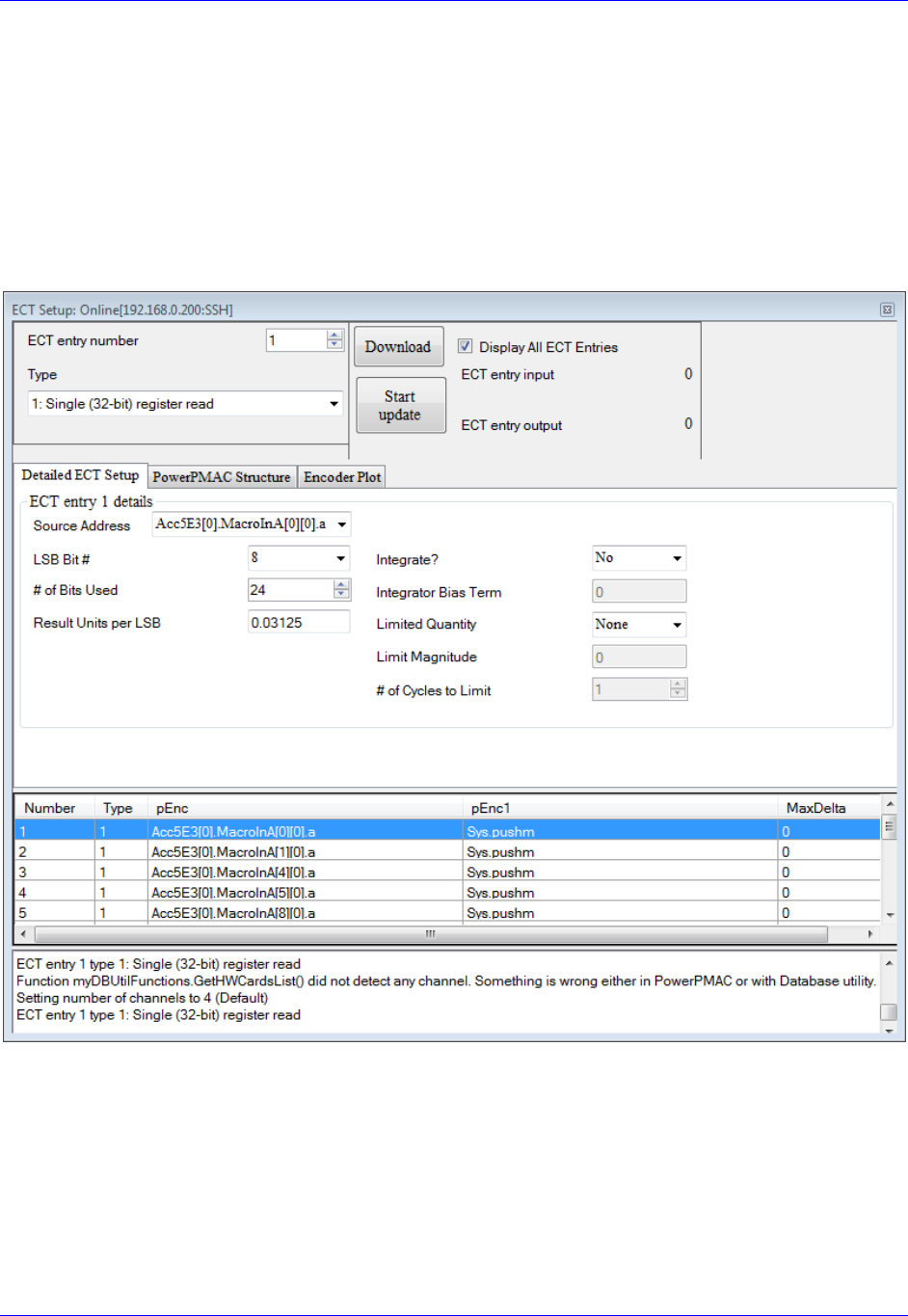
Accessory 24M2A
Configuring with Power PMAC 68
Motor Feedback
First, the user must make Encoder Conversion Table (ECT) entries on the Ring Controller to read the
feedback coming back from the ACC-24M2A on servo nodes. This applies to all feedback types that
ACC-24M2A uses.
Use the ECT entry type ngle (32-bit) register read), LSB Bit #: 8, # of Bits Used: 24. Make sure to
select the address based on the correct nodes enabled for this ACC-24M2A. One can set up the ECT entry
using the Power PMAC IDE by clicking (from within the software) on Delta TauConfigureEncoder
Conversion Table, showing this window:
The only field the user needs to change on this screen is the Source Address and the Entry Number. There
should be one entry for each motor, each using the Source Address that corresponds to the node used for
this motor. That is, make the Source Address match the address of the
node. Make the Entry Number whatever is desired as long as it does not conflict with an ECT entry
currently used for another motor.
For Gate3-Style MACRO interfaces, use Gate3[i].MacroInA[j][0].a for the encoder feedback Source
Address. For Gate2-Style interfaces, use Gate2[i].Macro[j][0].a.

Accessory 24M2A
Configuring with Power PMAC 69
Example: Motors 1–2 on Nodes 0 and 1, respectively, with a Gate3-Style MACRO Interface on card
index 0
EncTable[1].pEnc=Gate3[0].MacroInA[0][0].a;
EncTable[1].pEnc1=Sys.pushm;
EncTable[1].Index1=8;
EncTable[1].Index2=8;
EncTable[1].Index3=0;
EncTable[1].Index4=0;
EncTable[1].ScaleFactor=1/exp2(EncTable[1].Index1 + 5);
EncTable[2].pEnc=Gate3[0].MacroInA[1][0].a;
EncTable[2].pEnc1=Sys.pushm;
EncTable[2].Index1=8;
EncTable[2].Index2=8;
EncTable[2].Index3=0;
EncTable[2].Index4=0;
EncTable[2].ScaleFactor=1/exp2(EncTable[2].Index1 + 5);
Motor[x].pEnc (position feedback pointer) and Motor[x].pEnc2 (velocity
feedback pointer) to the numerical hex value Processed Data Address listed the ECT window shown
above. The user must also set the Encoder Type (Motor[x].EncType) to 4.
Example: Motors 1–2 Motor[x].pEnc and Motor[x].pEnc2 setting:
Motor[1].pEnc=EncTable[1].a;
Motor[1].pEnc2=EncTable[1].a;
Motor[2].pEnc=EncTable[2].a;
Motor[2].pEnc2=EncTable[2].a;
Motor[1].EncType=4;
Motor[2].EncType=4;
Typically, Motor[x].pEnc and Motor[x].pEnc2 point to the same address. However, if the user wants to
use dual feedback on ACC-24M2A and is therefore using both encoder channels for one motor, the user
must make one ECT entry for each encoder and point Motor[x].pEnc to the position encoder
ent and Motor[x].pEnc2 to the velocity encoder.

Accessory 24M2A
Configuring with Power PMAC 70
Digital A Quad B
The user must configure the Encoder Conversion Table on the ACC-24M2A itself as follows:
Example: ACC-24M2A with two motors, one on Node 0, one on Node 1
// ACC-24M2A ECT Setup for Quadrature Encoders
MacroSlave0,MI120=$0C090 // 1/T Extension of Incremental Encoder Ch1
MacroSlave0,MI121=$0C098 // 1/T Extension of Incremental Encoder Ch2
// ACC-24M2A ECT Output Setup
MacroSlave0,MI101=$10 // Output from 1st line of ECT (MI120)
MacroSlave0,MI102=$11 // Output from 2nd line of ECT (MI121)
If the user wants to change the direction of the encoder feedback, he or she can either:
Change MacroSlave<node>, MI910:
If MI910=3, set it to 7 (clockwise rotation is positive)
If MI910=7, set it to 3 (counterclockwise rotation is positive)
Sinusoidal
The user must configure the Encoder Conversion Table on the ACC-24M2A itself as follows:
Example: ACC-24M2A with two motors, one on Node 0, one on Node 1
// ACC-24M2A ECT Setup for Sinusoidal Encoders
// Channel 1
MacroSlave0,MI120=$F0C090 // Data Source Address location
MacroSlave0,MI121=$FF00 // A/D Converter Address Setup
MacroSlave0,MI122=0 // Sine/Cosine Bias –User Input
// Channel 2
MacroSlave0,MI123=$F0C098 // Data Source Address location
MacroSlave0,MI124=$FF20 // A/D Converter Address Setup
MacroSlave0,MI125=0 // Sine/Cosine Bias –User Input
// ACC-24M2A ECT Output Setup
MacroSlave0,MI101=$12 // Output from 3rd line of ECT (MI122)
MacroSlave0,MI102=$15 // Output from 6th line of ECT (MI125)
Note that the third line of the entry for each channel (in this example, MI122 for Channel 1 and MI124 for
Channel 2) contains the bias in the A/D converter values. The user should enter into this line (indicated by
User Input in the comment of that line) the value that the A/D converters report when they should
ideally report zero. The MACRO Station subtracts this value from both A/D readings before calculating
the arctangent. Many users will leave this value at 0, but to remove the offsets of single-ended analog
encoder signals is particularly useful. If it appears that the encoder has an offset, the user can compensate
for it in these variables. This line is scaled so that the maximum A/D converter reading provides the full
value of the 24-bit register (+/-223). Generally, it is set by reading the A/D converter values directly off of
the Station as 24-bit values (in this example, from Y:$C090 for Channel 1 and from Y:$C098 for Channel
2), computing the average value over a cycle or cycles, and entering this value here.
For more detail on how Sinusoidal Interpolation works in PMAC, see Appendix D.
Note
At this point of the setup process, you should be able to move the
motor/encoder shaft by hand and see encoder counts in the position
window

Accessory 24M2A
Configuring with Power PMAC 71
SSI
ACC-24M2A can be configured to process SSI encoder feedback as a binary parallel word in 12, 16, 20,
or 24-bit format. As with all feedback, this data is transferred across the MACRO ring to be used as
position and/or velocity feedback. Each SSI device requires three lines of the ECT.
In the second line of each SSI ECT entry, the number of bits to process is specified. So, there are four
examples given below.
In the third line, specify the maximum change per servo cycle of the encoder counts that is expected. This
is typically equal to 1.25 times the maximum expected velocity of the motor. The units of this entry
are whatever the units of the input register are, typically 1/32 of a count. For example, to limit the change
in one servo cycle to 64 counts with an input register in units of 1/32 count, this third line would be 64*32
= 2048.
In the examples below, the user must specify the maximum count change per servo cycle on the lines
-
Example: ACC-24M2A with two motors, each with a 12-bit SSI encoder, one on Node 0, one on
Node 1
#define MaxVelCh1 0 // Maximum count change per servo cycle, Channel 1 –User Input
#define MaxVelCh2 0 // Maximum count change per servo cycle, Channel 2 –User Input
// ACC-24M2A ECT Setup
//Channel 1
MacroSlave0,MI120=$30FF54 // Data Source Address location
MacroSlave0,MI121=$000FFF // 12-bit SSI conversion
MacroSlave0,MI122=MaxVelCh1*32
//Channel 2
MacroSlave0,MI123=$30FF74 // Data Source Address location
MacroSlave0,MI124=$000FFF // 12-bit SSI conversion
MacroSlave0,MI125=MaxVelCh2*32
// ACC-24M2A ECT output setup
MacroSlave0,MI101=$12 // Output from 3rd line of ECT (MI122)
MacroSlave0,MI102=$15 // Output from 6th line of ECT (MI125)
Example: ACC-24M2A with two motors, each with a 16-bit SSI encoder, one on Node 0, one on
Node 1
#define MaxVelCh1 0 // Maximum count change per servo cycle, Channel 1 –User Input
#define MaxVelCh2 0 // Maximum count change per servo cycle, Channel 2 –User Input
// ACC-24M2A ECT Setup
//Channel 1
MacroSlave0,MI120=$30FF54 // Data Source Address location
MacroSlave0,MI121=$00FFFF // 16-bit SSI conversion
MacroSlave0,MI122=MaxVelCh1*32
//Channel 2
MacroSlave0,MI123=$30FF74 // Data Source Address location
MacroSlave0,MI124=$00FFFF // 16-bit SSI conversion
MacroSlave0,MI125=MaxVelCh2*32
// ACC-24M2A ECT output setup
MacroSlave0,MI101=$12 // Output from 3rd line of ECT (MI122)
MacroSlave0,MI102=$15 // Output from 6th line of ECT (MI125)

Accessory 24M2A
Configuring with Power PMAC 72
Example: ACC-24M2A with two motors, each with a 20-bit SSI encoder, one on Node 0, one on
Node 1
#define MaxVelCh1 0 // Maximum count change per servo cycle, Channel 1 –User Input
#define MaxVelCh2 0 // Maximum count change per servo cycle, Channel 2 –User Input
// ACC-24M2A ECT Setup
//Channel 1
MacroSlave0,MI120=$30FF54 // Data Source Address location
MacroSlave0,MI121=$0FFFFF // 20-bit SSI conversion
MacroSlave0,MI122=MaxVelCh1*32
//Channel 2
MacroSlave0,MI123=$30FF74 // Data Source Address location
MacroSlave0,MI124=$0FFFFF // 20-bit SSI conversion
MacroSlave0,MI125=MaxVelCh2*32
// ACC-24M2A ECT output setup
MacroSlave0,MI101=$12 // Output from 3rd line of ECT (MI122)
MacroSlave0,MI102=$15 // Output from 6th line of ECT (MI125)
Example: ACC-24M2A with two motors, each with a 24-bit SSI encoder, one on Node 0, one on
Node 1
#define MaxVelCh1 0 // Maximum count change per servo cycle, Channel 1 –User Input
#define MaxVelCh2 0 // Maximum count change per servo cycle, Channel 2 –User Input
// ACC-24M2A ECT Setup
//Channel 1
MacroSlave0,MI120=$30FF54 // Data Source Address location
MacroSlave0,MI121=$FFFFFF // 24-bit SSI conversion
MacroSlave0,MI122=MaxVelCh1*32
//Channel 2
MacroSlave0,MI123=$30FF74 // Data Source Address location
MacroSlave0,MI124=$FFFFFF // 24-bit SSI conversion
MacroSlave0,MI125=MaxVelCh2*32
// ACC-24M2A ECT output setup
MacroSlave0,MI101=$12 // Output from 3rd line of ECT (MI122)
MacroSlave0,MI102=$15 // Output from 6th line of ECT (MI125)
Note
If the direction decode variable, MacroSlave<node>, MI910, is
changed the user must save the setting, MSSAVE{node} and reset the
card MS$$${node} before the fractional direction sense matches.
Note
At this point of the setup process, you should be able to move the
motor/encoder shaft by hand and see encoder counts in the position
window

Accessory 24M2A
Configuring with Power PMAC 73
Resolver
ECT Setup
ACC-24M2A has up to two channels of resolver inputs. The inputs may be used as feedback or master
reference signals for the PMAC servo loops. The basic configuration of the drive contains one 10-bit fixed
resolution tracking resolver-to-digital (R-to-D) converters, with an optional second resolver when a dual
axis driver is ordered. ACC-24M2A creates the AC excitation signal (ResOut) for up to two resolvers,
accepts the modulated sine and cosine signals back from these resolvers, demodulates the signals and
derives the position of the resolver from the resulting information, in an absolute sense if necessary.
The specifics for this configuration are as follows (Ch1 and Ch2):
Example: ACC-24M2A with two motors, each with a resolver, one on Node 0, one on Node 1,
wherein the clockwise direction of the motor’s shaft’s rotation is positive
// ACC-24M2A ECT Setup
// Channel 1
MacroSlave0,MI120=$E0FF00 // Data Source Address location ,CW
MacroSlave0,MI121=$00FF5C // A/D Converter Address Setup
MacroSlave0,MI122=0 // Sine/Cosine Bias –User Input
// Channel 2 CW
MacroSlave0,MI123=$E0FF20 // Data Source Address location, CW
MacroSlave0,MI124=$00FF5C // A/D Converter Address Setup
MacroSlave0,MI125=0 // Sine/Cosine Bias –User Input
// ACC-24M2A ECT Output Setup
MacroSlave0,MI101=$12 // Output from 3rd line of ECT (MI122)
MacroSlave0,MI102=$15 // Output from 6th line of ECT (MI125)
Example: ACC-24M2A with two motors, each with a resolver, one on Node 0, one on Node 1,
wherein the counterclockwise direction of the motor’s shaft’s rotation is positive
// ACC-24M2A ECT Setup
// Channel 1
MacroSlave0,MI120=$E8FF00 // Data Source Address location ,CCW
MacroSlave0,MI121=$00FF5C // A/D Converter Address Setup
MacroSlave0,MI122=0 // Sine/Cosine Bias –User Input
// Channel 2 CW
MacroSlave0,MI123=$E8FF20 // Data Source Address location, CCW
MacroSlave0,MI124=$00FF5C // A/D Converter Address Setup
MacroSlave0,MI125=0 // Sine/Cosine Bias –User Input
// ACC-24M2A ECT Output Setup
MacroSlave0,MI101=$12 // Output from 3rd line of ECT (MI122)
MacroSlave0,MI102=$15 // Output from 6th line of ECT (MI125)
Note that the third line of the entry for each channel (in this example, MI122 for Channel 1 and MI124 for
Channel 2) contains the bias in the A/D converter values. This line - in the
comments on that line) should contain the value that the A/D converters report when they should ideally
report zero. The MACRO Station subtracts this value from both A/D readings before calculating the
arctangent. Many users will leave this value at 0, but it is particularly useful to remove the offsets of
single-ended analog encoder signals. If it appears that the encoder has an offset, the user can compensate
for it in these variables. This line is scaled so that the maximum A/D converter reading provides the full
value of the 24-bit register (+/-223). Generally, it is set by reading the A/D converter values directly as 24-
bit values (in this example, from Y:$C090 for Channel 1 and from Y:$C098 for Channel 2), computing
the average value over a cycle or cycles, and entering this value here.

Accessory 24M2A
Configuring with Power PMAC 74
Note
If the direction decode variable, MacroSlave<node>, MI910, is
changed the user must save the setting, MSSAVE{node} and reset the
card MS$$${node} before the fractional direction sense matches.
Configuring Excitation Frequency
After setting up the ECT, the user then must set three MI-Variables for the Resolvers to function
correctly.
-24M2A is derived
from the Phase Clock frequency of the MACRO set by MI992 and MI997. The user has the ability to
select the excitation frequency to be equal with the Phase Clock frequency (default) by setting
MacroSlave<node>,MI982 equal to 0. Or, the user can use lower frequencies by increasing the value of
MI982.
MI982 affects the excitation frequency as follows:
MI982 Setting
Excitation Frequency
MI982=1
(Phase Clock Frequency)/2
MI982=2
(Phase Clock Frequency)/4
MI982=3
(Phase Clock Frequency)/6
Configuring the Excitation Signal’s Gain
MacroSlave<node>,MI981.
MI981 Setting
Excitation Signal Gain
MI981=0
2.5 Vpp
MI981=1
5.0 Vpp
MI981=2
7.5 Vpp
MI981=3
10.0 Vpp

Accessory 24M2A
Configuring with Power PMAC 75
Configuring the Excitation Signal’s Phase Offset
Finally the resolver excitation phase time offset, MacroSlave<node>, MI980, needs to be set. The
optimum setting of MI980 depends on the L/R time constant of the resolver circuit. Therefore, MI980
should be set interactively to maximize the magnitudes of the feedback ADC values.
For each channel, there are two ADC registers which hold the sin and cosine values. For Channel 1, the
base/first ADC register address is Y:$FF00 and the second ADC register address is Y:$FF01; For
Channel 2, the base/first ADC register address is Y:$FF20 and the second ADC register address is
Y:$FF21. There is no MI-Variable to directly address these registers, so MI198 (Direct Read/Write Format
and Address) and MI199 (Direct Read/Write Variable) will be used here. For each channel, both ADCs
should be observed during setup. Notice that MI199 can only be pointed to one register at one time so it
must be configured twice throughout the following procedure.
Procedure for Configuring MI980 on Channel 1
The procedure for configuring MI980 for Channel 1 is as follows:
9. In the Power PMAC IDE, open a Watch Window (click Delta TauViewWatch).
10. Into a field in the Watch Window, type MacroSlave<node>,MI199, where <node> is the node
number of this ACC-MacroSlave0,MI199).
11. In the Terminal Window (from within the IDE, click Delta TauViewTerminal), type
MacroSlave<node>,MI198=$6DFF00, where <node>
12. Rotate the motor on this channel. Observe MacroSlave<node>,MI199 in the Watch Window. If
it saturates to ±32767, the resolver gain (MI981) is too high. Decrease MI981 until the MI199 just
barely saturates to ±32767. If it does not saturate, type MacroSlave<node>,MI198=$6DFF01 in
the Terminal Window (which sets MI199 to point to
13. Set MI199 to point to the ADC which saturated; that is, if ADC1 saturated, type
MacroSlave<node>,MI198=$6DFF00 in the Terminal Window, or if ADC2 saturated, type
MacroSlave<node>,MI198=$6DFF01 in the Terminal Window.
14.
15. Increase MI980 by increments of 25. The ADC value should start to increase slowly. If it
decreases, instead start with MI980=255 and then decrease MI980 by increments of 25. The ADC
value should increase up to a maximum point and then start to decrease again. Set MI980 to the
value that produced the largest absolute ADC value achieved throughout the process of adjusting
MI980.
16. If the maximum absolute value of this ADC is less than 16,000, increase the gain of the resolver
by increasing MI981.

Accessory 24M2A
Configuring with Power PMAC 76
Procedure for Configuring MI980 on Channel 2
The procedure for configuring MI980 for Channel 2 is as follows:
9. In the Power PMAC IDE, open a Watch Window (click Delta TauViewWatch Window).
10. Into a field in the Watch Window, type MacroSlave<node>,MI199, where <node> is the node
number of this ACC-MacroSlave0,MI199).
11. In the Terminal Window (from within the IDE, click Delta TauViewTerminal), type
MacroSlave<node>,MI198=$6DFF20, where <node> in step 2). This
12. Rotate the motor on this channel. Observe MacroSlave<node>,MI199 in the Watch Window. If
it saturates to ±32767, the resolver gain (MI981) is too high. Decrease MI981 until the MI199 just
barely saturates to ±32767. If it does not saturate, type MacroSlave<node>,MI198=$6DFF21 in
13. Set MI199 to point to the ADC which saturated; that is, if ADC1 saturated, type
MacroSlave<node>,MI198=$6DFF20 in the Terminal Window, or if ADC2 saturated, type
MacroSlave<node>,MI198=$6DFF21 in the Terminal Window.
14.
throughout one revolution of the
15. Increase MI980 by increments of 25. The ADC value should start to increase slowly. If it
decreases, instead start with MI980=255 and then decrease MI980 by increments of 25. The ADC
value should increase up to a maximum point and then start to decrease again. Set MI980 to the
value that produced the largest absolute ADC value achieved throughout the process of adjusting
MI980.
16. If the maximum absolute value of this ADC is less than 16,000, increase the gain of the resolver
by increasing MI981.
Note
At this point of the setup process, you should be able to move the
motor/encoder shaft by hand and see encoder counts in the position
window

Accessory 24M2A
Configuring with Power PMAC 77
Flags
On the Ring Controller, tpointers
the motors on ACC-24M2A.
Example: Motors 1–2 on Nodes 0 and 1, respectively, using ACC-5E3 in a Power UMAC
Motor[1].pEncCtrl=Acc5E3[0].MacroOutA[0][3].a
Motor[1].pEncStatus=Acc5E3[0].MacroInA[0][3].a
Motor[1].pAmpEnable=Acc5E3[0].MacroOutA[0][3].a
Motor[1].pAmpFault=Acc5E3[0].MacroInA[0][3].a
Motor[1].pCaptFlag=Acc5E3[0].MacroInA[0][3].a
Motor[1].pPhaseEnc=Acc5E3[0].MacroInA[0][0].a
Motor[1].pAdc=Acc5E3[0].MacroInA[0][1].a
Motor[2].pEncCtrl=Acc5E3[0].MacroOutA[1][3].a
Motor[2].pEncStatus=Acc5E3[0].MacroInA[1][3].a
Motor[2].pAmpEnable=Acc5E3[0].MacroOutA[1][3].a
Motor[2].pAmpFault=Acc5E3[0].MacroInA[1][3].a
Motor[2].pCaptFlag=Acc5E3[0].MacroInA[1][3].a
Motor[2].pPhaseEnc=Acc5E3[0].MacroInA[1][0].a
Motor[2].pAdc=Acc5E3[0].MacroInA[1][1].a
Then, on the Ring Controller, the flag control variables must be set up for each motor on ACC-24M2A.
Example: Motors 1–2 on Nodes 0 and 1, respectively, with overtravel limits enabled, using ACC-
5E3 in a Power UMAC
Motor[1].pLimits=Acc5E3[0].MacroInA[0][3].a
Motor[1].LimitBits=25
Motor[1].CaptPosRound=1
Motor[1].CaptPosRightShift=0
Motor[1].CaptPosLeftShift=13
Motor[1].CaptFlagBit=19
Motor[1].AmpFaultBit=23
Motor[1].AmpEnableBit=22
Motor[1].AmpFaultLevel=0
Motor[2].pLimits=Acc5E3[0].MacroInA[1][3].a
Motor[2].LimitBits=25
Motor[2].CaptPosRound=1
Motor[2].CaptPosRightShift=0
Motor[2].CaptPosLeftShift=13
Motor[2].CaptFlagBit=19
Motor[2].AmpFaultBit=23
Motor[2].AmpEnableBit=22
Motor[2].AmpFaultLevel=0

Accessory 24M2A
Configuring with Power PMAC 78
Example: Motors 1–2 on Nodes 0 and 1, respectively, with overtravel limits disabled
Motor[1].pLimits=0;
Motor[1].LimitBits=25
Motor[1].CaptPosRound=1
Motor[1].CaptPosRightShift=0
Motor[1].CaptPosLeftShift=13
Motor[1].CaptFlagBit=19
Motor[1].AmpFaultBit=23
Motor[1].AmpEnableBit=22
Motor[1].AmpFaultLevel=0
Motor[2].pLimits=0;
Motor[2].LimitBits=25
Motor[2].CaptPosRound=1
Motor[2].CaptPosRightShift=0
Motor[2].CaptPosLeftShift=13
Motor[2].CaptFlagBit=19
Motor[2].AmpFaultBit=23
Motor[2].AmpEnableBit=22
Motor[2].AmpFaultLevel=0
Output Commands
On the Ring Controller, the output command address must be set to the ACC-
node addresses directly.
Example: Motors 1–2 on Nodes 0 and 1, respectively, using ACC-5E3 in a Power UMAC
Motor[1].pDac=Acc5E3[0].MacroOutA[0][0].a;
Motor[2].pDac=Acc5E3[0].MacroOutA[1][0].a;
Note
These examples configure only motors 12. If you are configuring
other motors, refer to the Power PMAC Software Reference Manual
for the different settings the aforementioned structures can take.

Accessory 24M2A
Configuring with Power PMAC 79
I2T Settings
The I2T overcurrent protection should be configured for each motor on ACC-24M2A. Below is an
example with some formulas for setting up I2T; the user simply needs to fill in the values specified by
-:
Example: Configuring I2T Protection for Motors 1–2
#define Axis1MinContCurrent 3 ; Continuous Current Limit for Axis 1 [Amps] –User Input
#define Axis1MinPeakCurrent 9 ; Instantaneous Current Limit for Axis 1 [Amps] –User Input
#define Axis1AmpPeakInstCurrent 16.3 ; Peak Instant. Current of Amplifier [Amps] –User Input
#define Axis1I2TOnTime 2 ; Time allowed at peak current [sec]
// Assuming that motor 1 is the first motor on MACRO
Motor[1].I2TSet=32767*Axis1MinContCurrent/Axis1AmpPeakInstCurrent
Motor[1].MaxDac=32767*Axis1MinPeakCurrent/Axis1AmpPeakInstCurrent
Motor[1].I2TTrip=(Motor[1].MaxDac*Motor[1].MaxDac - Motor[1].I2TSet*Motor[1].I2TSet +
Motor[1].IdCmd*Motor[1].IdCmd)*Axis1I2TOnTime
Motor[2].I2TSet=Motor[1].I2TSet // Assumes motor 2 is the same as motor 1
Motor[2].MaxDac=Motor[1].MaxDac // Assumes motor 2 is the same as motor 1
Motor[2].I2TTrip=Motor[1].I2TTrip // Assumes motor 2 is the same as motor 1
The continuous current limit (Axis1MinContCurrent) and the instantaneous current limit
(Axis1MinPeakCurrent- the comment above should be the
DAC Calibration
WARNING
Before performing the DAC Calibration, make sure there is no
load attached to the motor, and make sure that the motor can
safely and freely move. This step of the setup can generate much
motion in the motor.
At this stage in the setup, the user should calibrate the DACs on ACC-24M2A to make sure that when he
or she commands 0 volts on the DACs, they actually put out 0 volts. You can do this by means of the
automatic DAC calibration program from the Power PMAC System Setup program, easily accessible by
means of a TelNet Terminal connection to your PMAC. To open a TelNet connection, from the Windows
Start Menu click StartRun (or just type into the search field if it is Windows Vista/7) and then type:
telnet 192.168.0.200
here type:
root
The password is:
deltatau
Then, type:
cd setup
dir

Accessory 24M2A
Configuring with Power PMAC 80
calcdacbias should appear as a program in the list. This is a program that receives two arguments as
follows:
calcdacbias <MotorNumber> [<Iterations>]
<MotorNumber> is the number of the motor whose DAC bias you want to calculate. [<Iterations>] is the
number of times you want the program to iterate; more iterations generally yields a more accurate result.
Example
To calculate the DAC bias of motor 1 with 10 iterations, type:
calcdacbias 1 10
Once the program completes, it will issue a command to PMAC to change the DAC bias for this motor.
For example, after entering the above command, the final iteration of the program will print something to
the effect of:
Command: Motor[1].DacBias = -139.200000
You may want to write down this number and put it into your motor setup file in your project within the
Power PMAC IDE for future reference.
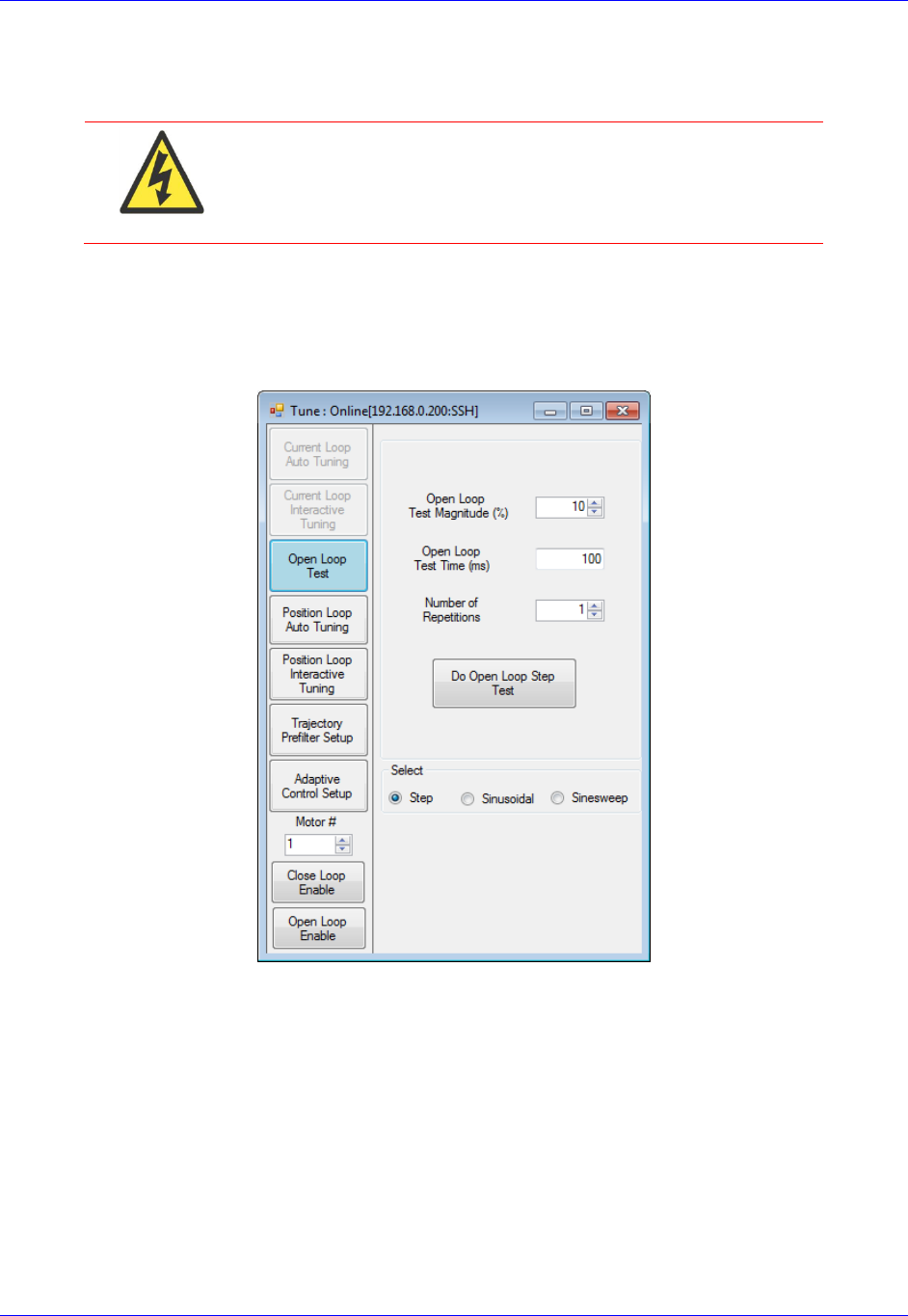
Accessory 24M2A
Configuring with Power PMAC 81
Open Loop Test
WARNING
Before performing the Open Loop Test, make sure there is no
load attached to the motor, and make sure that the motor can
safely and freely move. This step of the setup can generate much
motion in the motor.
The user should now execute an Open-Loop test in order to determine whether the feedback from ACC-
24M2A is working properly. To do this, open Tuning from the Power PMAC IDE by clicking on
ToolsTune. Then, click the Open Loop Test button on the left:
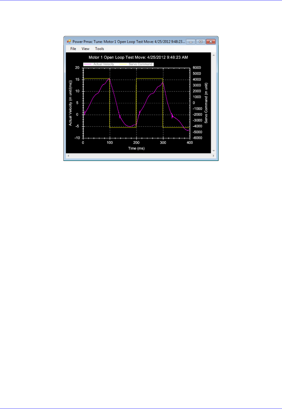
Accessory 24M2A
Configuring with Power PMAC 82
You should see the actual velocity increasing positively while the commanded velocity is positive, the
actual velocity decreasing while the commanded velocity is negative, looking something like this:
If you see an erratic response, or an inverted saw tooth, then most likely the encoder decode setting is
incorrect. To change this, change MS{node},MI910 for this motor from 7 to 3, or vice versa.

Accessory 24M2A
Configuring with Power PMAC 83
Servo Loop Tuning
amplifiers. Configuration is done by adjusting setup structures pertaining to the PID gains. Friction
Feedforward is also needed. The servo loop gains correspond to structures as follows:
Motor[x].Servo.Kp Proportional Gain (Kp)
Motor[x].Servo.Kvfb Derivative Gain (Kd)
Motor[x].Servo.Kvff Velocity Feedforward (Kvff)
Motor[x[.Servo.Ki Integral Gain (Ki)
Motor[x].Servo.SwZvInt Integration Mode
Motor[x].Kaff Acceleration Feedforward (Kaff)
Motor[x].Kfff Friction Feedforward (Kfff)
Note
The user should connect the load to the motor before tuning the servo
loop.
. The procedure for tuning is as
follows:
4. Set Motor[x].Servo.SwZvInt (Motor xx PID Integration Mode) can be changed on the fly as
needed
=1, position error integration is performed only when Motor xx is not commanding a move
=0, position error integration is performed always
5. Using the Step Response, tune the following parameters in this order:
Proportional Gain, Kp (Motor[x].Servo.Kp)
Derivative Gain, Kd (Motor[x].Servo.Kvfb)
Integral Gain, Ki (Motor[x[.Servo.Ki)
6. Using the Parabolic Move, tune the following parameters in this order:
Velocity Feedforward, Kvff (Motor[x].Servo.Kvff)
Acceleration Feedforward, Kaff (Motor[x].Kaff )
Friction Feedforward, Kfff (Motor[x].Kfff)
Note
When tuning the feedforward gains, set
Motor[x].Servo.SwZvInt =1 so that the dynamic behavior of
the system may be observed without integrator action. After
tuning these, set Motor[x].Servo.SwZvInt back to your
desired setting.
Setting Kvff = Kd (Motor[x].Servo.Kvff =
Motor[x].Servo.Kvfb) is a good place to start when tuning
Kvff.
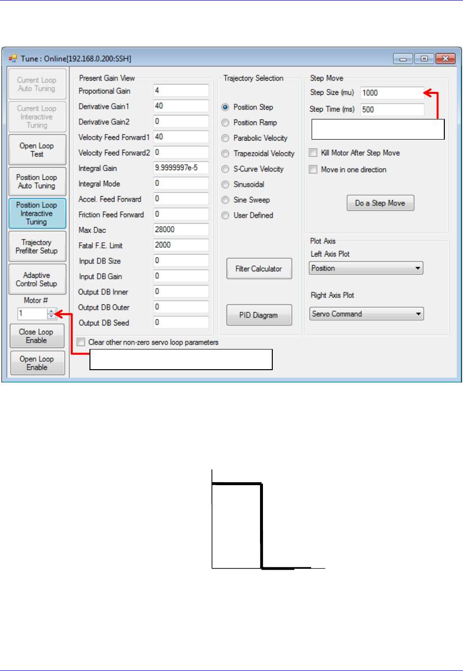
Accessory 24M2A
Configuring with Power PMAC 84
Steps 2 and 3 should be performed in the Interactive Tuning window in Tuning:
Step 2 (tuning Kp, Kd, and Ki)
S
within ½ to ¼ of a revolution of the motor if it is a rotary motor, or within ½ to ¼ of one electrical cycle if
it is a linear motor. The step mo
position looks, adjust the servo loop gains until you achieve the desired response.
Time [sec]
Commanded
Position [cts]
Select the Motor Number here
Input the move size here
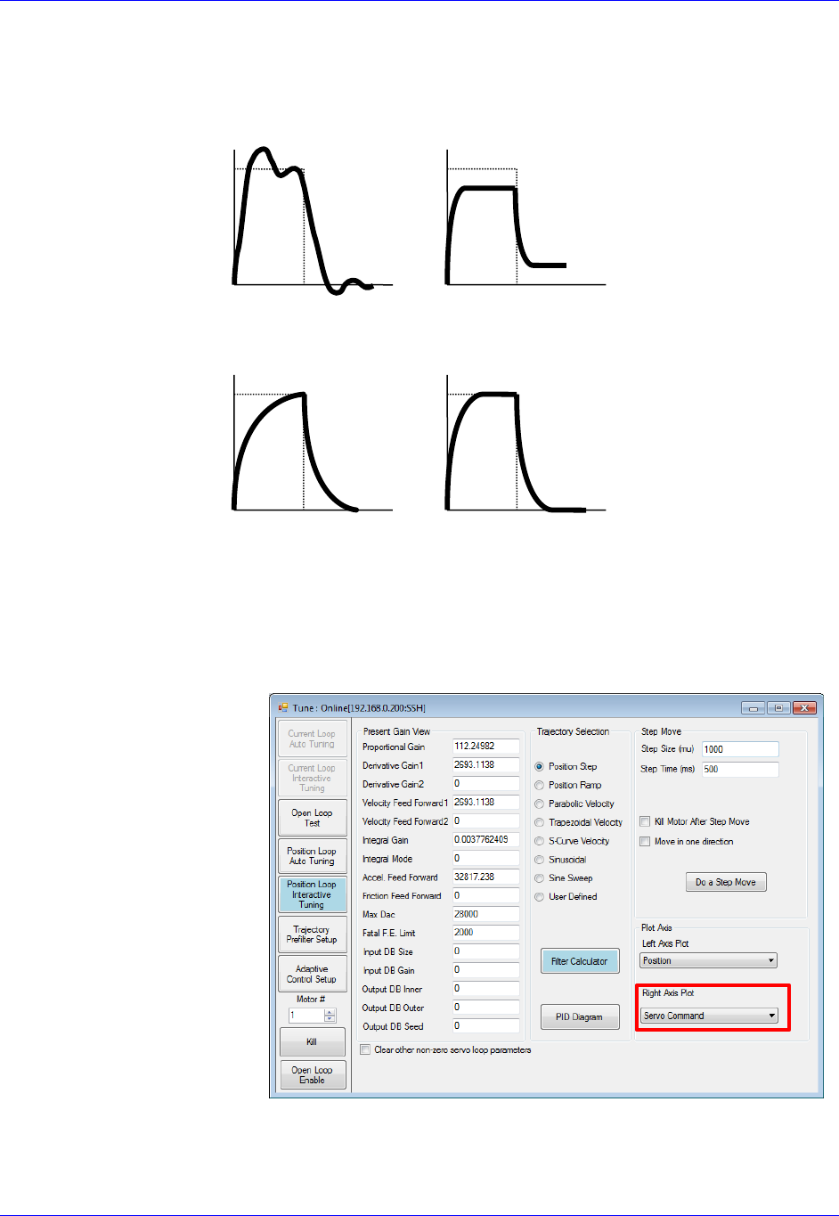
Accessory 24M2A
Configuring with Power PMAC 85
Observing the table below, match your actual position response to one of the response shapes below, and
then adjust the appropriate gain as listed next to each plot:
Overshoot and
Oscillation
Cause:
Too much Proportional
gain or
too little Damping
Fix:
Decrease Kp
Increase Kd
Position Offset
Cause:
Friction or Constant
Force
Fix:
Increase Ki
Increase Kp
Sluggish Response
Cause:
Too much Damping or
too little Proportional
gain
Fix:
Increase Kp or
Decrease Kd
Physical System
Limitation
Cause:
Limit of the
Motor/Amplifier/Load
and gain combination
Fix:
Evaluate Performance
and
maybe add Kp
Typically, one should start by increasing Kp
d and Ki until the performance goals for the step response
are achieved. Be sure when executing the step response that you plot the Servo Command on the Right
Axis (see image on right below).
If you see a truncation of the
servo command at the
beginning of each move, you
have reached the maximum
output command as determined
by Motor[x].MaxDac. In this
case, adding more Kp will not
performance.
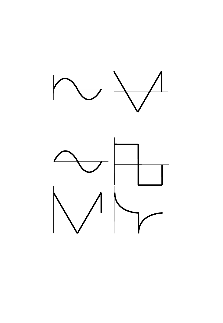
Accessory 24M2A
Configuring with Power PMAC 86
Step 3 (Tuning Kvff, Kaff, and Kfff)
S
move size and speed that will simulate the fastest, harshest moving conditions you expect your machine
to experience. Tune the motor at these settings, and then the motor should be able to handle all easier
moves.
After commanding the Parabolic Velocity move, the commanded Velocity Profile and Acceleration
Profile should look like this:
Velocity
Commanded
Profile
Acceleration
Commanded
Profile
Observing the table below, match your actual position response to one of the response shapes below, and
then adjust the appropriate gain as listed next to each plot:
High Vel./F.E.
Correlation
Cause: Damping
Fix: Increase Kvff
High Vel./F.E.
Correlation
Cause: Friction
Fix:
Add Kfff
and/or turn on Integral
Gain (Ki)
High Acc./F.E.
Correlation
Cause: Inertial Lag
Fix:
Increase Kaff
High Acc./F.E.
Correlation
Cause:
Physical System
Limitation
Fix:
Use softer acceleration
or add more Kfff

Accessory 24M2A
Configuring with Power PMAC 87
Negative Vel./F.E.
Correlation
Cause:
Too much Velocity
Feedforward
Fix:
Decrease Kvff
High Vel./F.E.
Correlation
Cause: Damping &
Friction
Fix:
Increase Kvff first
Possibly adjust Kfff
Negative Acc./F.E.
Correlation
Cause:
Too much
Acceleration
Feedforward
Fix:
Decrease Kaff
High Vel./F.E. &
Acc./F.E.
Correlation
Cause:
Inertial Lag &
Friction
Fix:
Increase Kaff
Possibly adjust Kfff
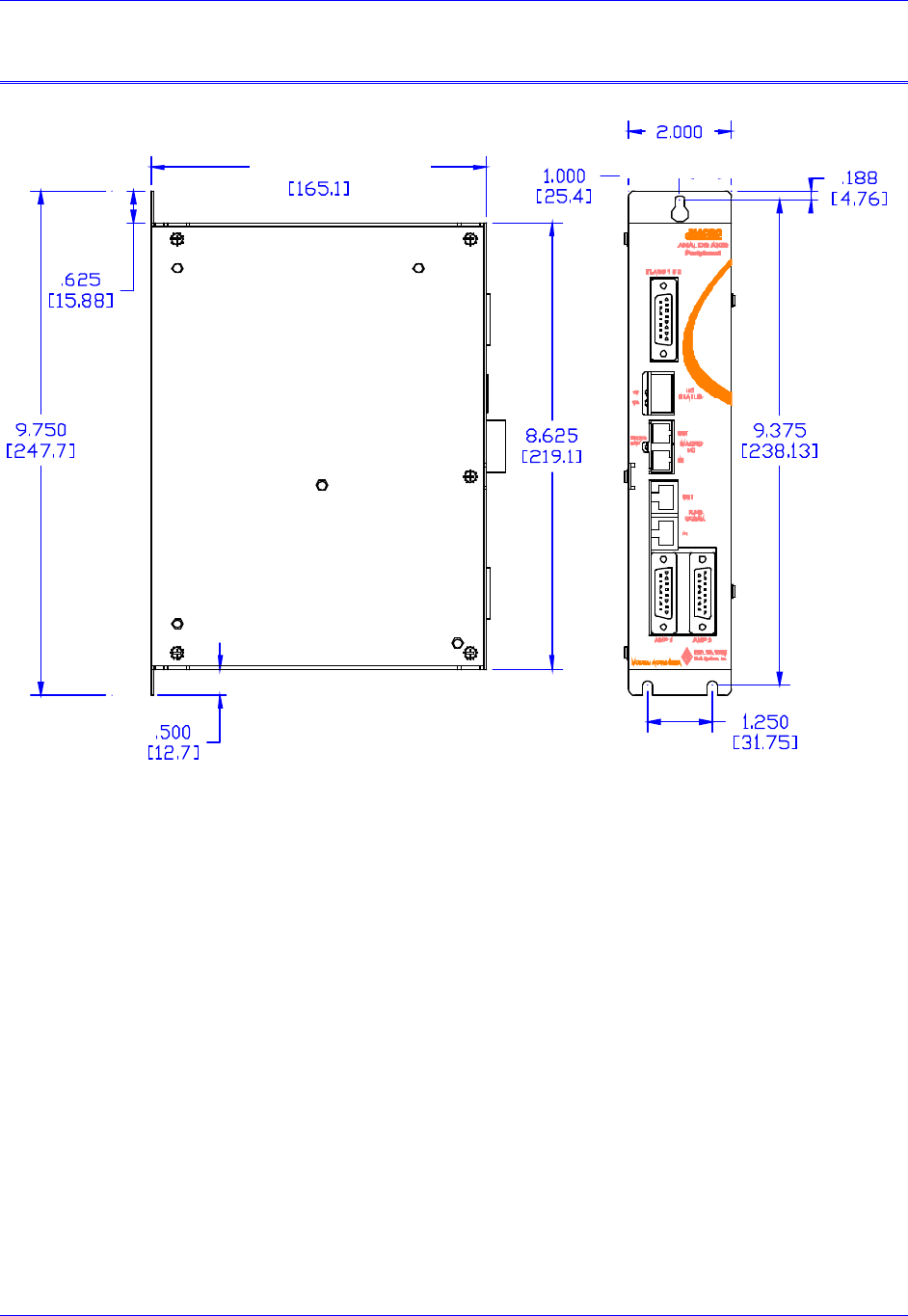
Accessory 24M2A
layout 88
LAYOUT
All main dimensions are in units of inches (millimeters are in square brackets).
Accessory 24M2A
appendix A: Jumpers 89
APPENDIX A: JUMPERS
Jumper
Name
Description
Default
E0
2
1
Lattice Download
Remove jumper to disable ability to perform Lattice
Download.
Jump pins 1 and 2 to enable ability to download.
Not
jumpered
E1
2
1
Watchdog Timer
Disable
Remove jumper to enable Watchdog Timer.
Jump pins 1 and 2 to disable Watchdog Timer (for test
purposes only)
Not
jumpered
E2
3
2
1
CPU Mode
Operation/Bootstrap
Jump pins 1 and 2 for firmware download through USB port.
Jump pins 2 and 3 for normal operation.
Pin 2-3
E3
2
1
Buffer Request
Select Polarity
Remove jumper to allow BRSEL- to 5Vdc
Jump pins 1 and 2 to pull BRSEL- to 0Vdc
Not
jumpered
E5
2
1
Encoder / Pulse and
Direction Ch1
Remove jumper to enable +/-10V analog output on Ch1
Jump pins 1 and 2 to enable Stepper mode output for Ch1
Not
jumpered
E6
2
1
Encoder / Pulse and
Direction Ch2
Remove jumper to enable +/-10V analog output on Ch1
Jump pins 1 and 2 to enable Stepper mode output on Ch2
Not
jumpered
E9
2
1
Stepper Drive
Amplifier Enable
Ch1
Remove jumper to receive encoder C-Channel input on Ch1.
Jump pins 1 and 2 to provide Amp Enable line for Stepper
Motor-style amplifier Ch1.
Not
jumpered
E10
2
1
Stepper Drive
Amplifier Enable
Ch2
Remove jumper to receive encoder C-Channel input on Ch2.
Jump pins 1 and 2 to provide Amp Enable line for Stepper
Motor-style amplifier Ch2.
Not
jumpered
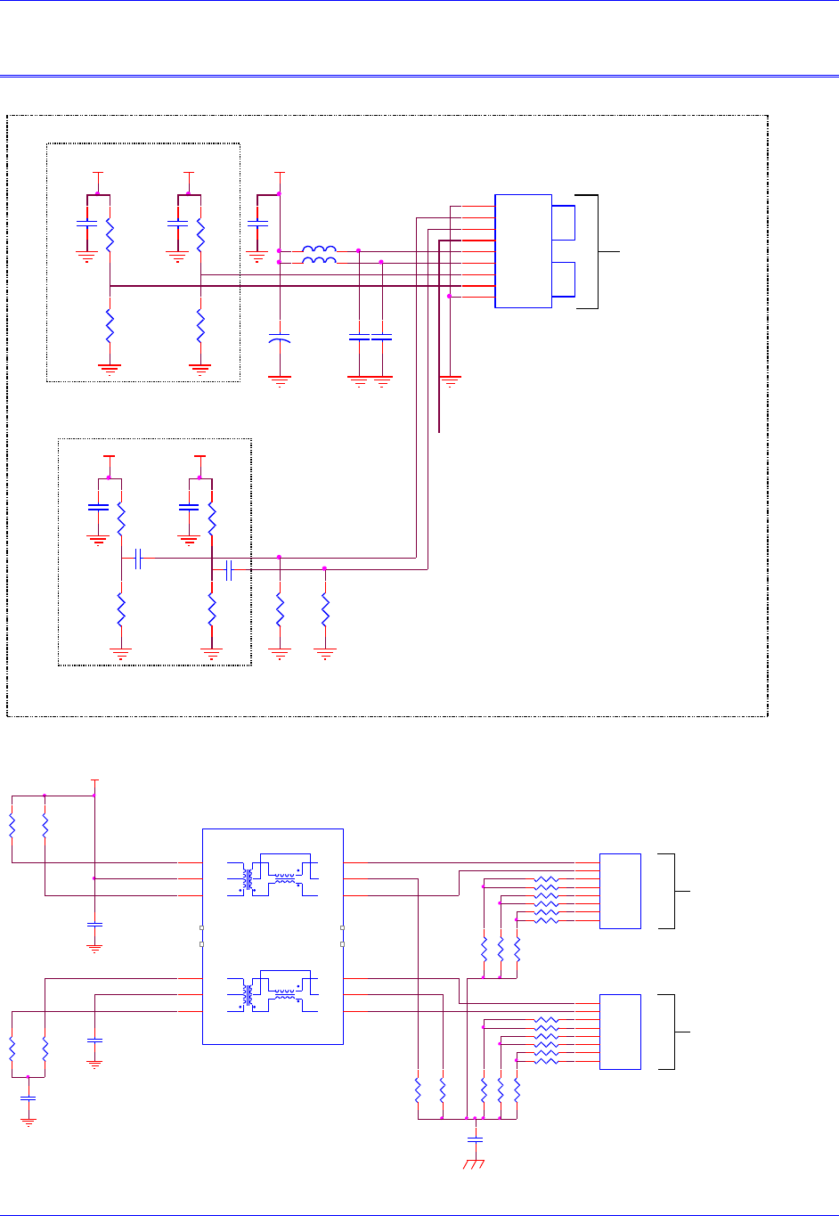
Accessory 24M2A
Appendix B: Schematics 90
APPENDIX B: SCHEMATICS
MACRO Fiber Connection
MACRO RJ45 Connection
U35
HFBR-5803
RXVEE
1
RD+
2
RD-
3
SD
4
RXVCC
5
TXVCC
6
TD-
7
TD+
8
TXVEE
9
C402
.1UF C403
.1UF
R41
4.99K
R43
7.5K
C400
.1UF R42
4.99K
R44
7.5K
OPT A - FIBER MACRO ONLY
C401
.1UF
LVPECL Termination Network Located
at Ethernet Transceiver Inputs
FXR+/FXR- (NEAR U31 AM79C874)
+3.3VD +3.3VD +3.3VD
C117
.1 uF
C118
.1 uF
+3.3VD
FBL22
FBL21
+3.3VD
R70
82 R71
82
C115
0.1 uF
+
C116
10 uF 3.3/5.0 Volt Fiber
Optic Transceiver
R39
187.0
LVPECL Termination Network Located
at Optical Transceiver Inputs TD+/TD-
(NEAR U35 HFBR-5803)
R40
187.0
Analog Ground
MACRO Over Fiber
C113
0.1 uF
C114
0.1 uF R38
68.1
R37
68.1
R405 51
R400 51
R401 51
R402 51
R403 51
R404 51
+3.3VD
R407 51
R406 51
R409 51
R411 51
R408 51
R410 51
R51
49.9 R52
49.9
R63
51
R61
51
R62
51
C111
.1UF
rj45
J5
RJ-45-8
1
2
3
4
5
6
7
8
J4
J5
J4
RJ-45-8
1
2
3
4
5
6
7
8
rj45
R68
51
R67
51
R66
51
C112
.1UF
C106
.1UF
R53
49.9 R54
49.9
R64
51
R65
51
(Receive)
MACRO Over Copper
Chassis Ground
(Transmit)
MACRO Over Copper
C109
.01 uF (3KV)
U32
TG110-S050N2
TX+ 3
TX- 1
CT 2
TD-
16
CT
15
TD+
14
RX- 6
CT 7
RX+ 8
RD-
11
CT
10
RD+
9
n.c.
4
n.c.
5
n.c.
12
n.c.
13
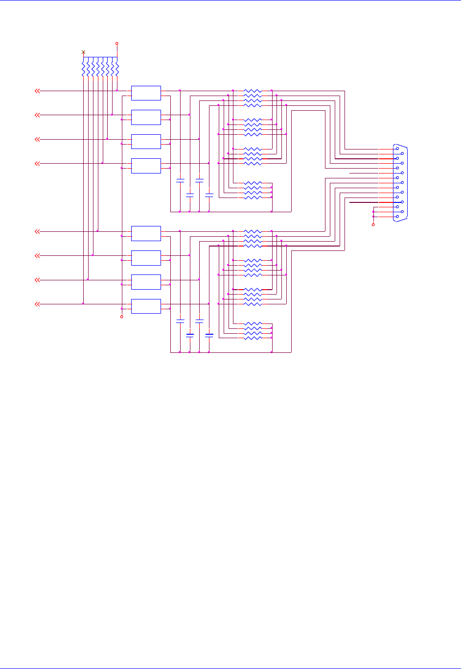
Accessory 24M2A
Appendix B: Schematics 91
Limit Inputs
FLAG_C2
FLAG_C1
FLAG_B2
C146 .1
C153 .1
U63A
PS2505L-1NEC
(SMT4)
ACI1A 1
ACI1B 2
E1
3C1
4
FLAG_B1
U63B
PS2505L-1NEC
(SMT4)
ACI1A 1
ACI1B 2
E1
3C1
4
U63D
PS2505L-1NEC
(SMT4)
ACI1A 1
ACI1B 2
E1
3C1
4
U63C
PS2505L-1NEC
(SMT4)
ACI1A 1
ACI1B 2
E1
3C1
4
RP43
1KSIP8I
12 34 56 78
RP36
4.7KSIP8I
1 2
3 4
5 6
7 8
FLAG_A2
RP38
x1KSIP8I
(IN SOCKET)
1 2
3 4
5 6
7 8
J6
DB15S
8
15
7
14
6
13
5
12
4
11
3
10
2
9
1
GND
USER1
MLIM1
PLIM1
HOME1
FL_RT1
USER2
MLIM2
PLIM2
HOME2
FL_RT2
U62C
PS2505L-1NEC
(SMT4)
ACI1A 1
ACI1B 2
E1
3C1
4
U62A
PS2505L-1NEC
(SMT4)
ACI1A 1
ACI1B 2
E1
3C1
4
U62B
PS2505L-1NEC
(SMT4)
ACI1A 1
ACI1B 2
E1
3C1
4
U62D
PS2505L-1NEC
(SMT4)
ACI1A 1
ACI1B 2
E1
3C1
4
FLAG_D12
FLAG_B12
FLAG_C12
FLAG_A12
FLAG_B22
FLAG_C22
FLAG_D22
FLAG_A22
USER1
USER2
MLIM1
PLIM1
BEQU2
MLIM2
BEQU1
HOME2
FL_RT1
HOME1
PLIM2
FL_RT2
MLIM2
FL_RT1
HOME2
GND
LIMITS 1,2
GND
PLIM1
USER2
GND
USER1
BEQU1
BEQU2
FL_RT2
HOME1
PLIM2
MLIM1
C150 .1
FLAG_D2
C152 .1
+5V
GND
RP42
x1KSIP8I
(IN SOCKET)
1 2
3 4
5 6
7 8
FLAG_D1
C148 .1
C149 .1
RP41
4.7KSIP8I
12 34 56 78
FLAG_A1
RP40
4.7KSIP8I
1 2
3 4
5 6
7 8
C151 .1
RP37
4.7KSIP8I
12 34 56 78
C147 .1
RP39
1KSIP8I
12 34 56 78
RP35
3.3KSIP10C
12
3
4
5
6
7
8
910
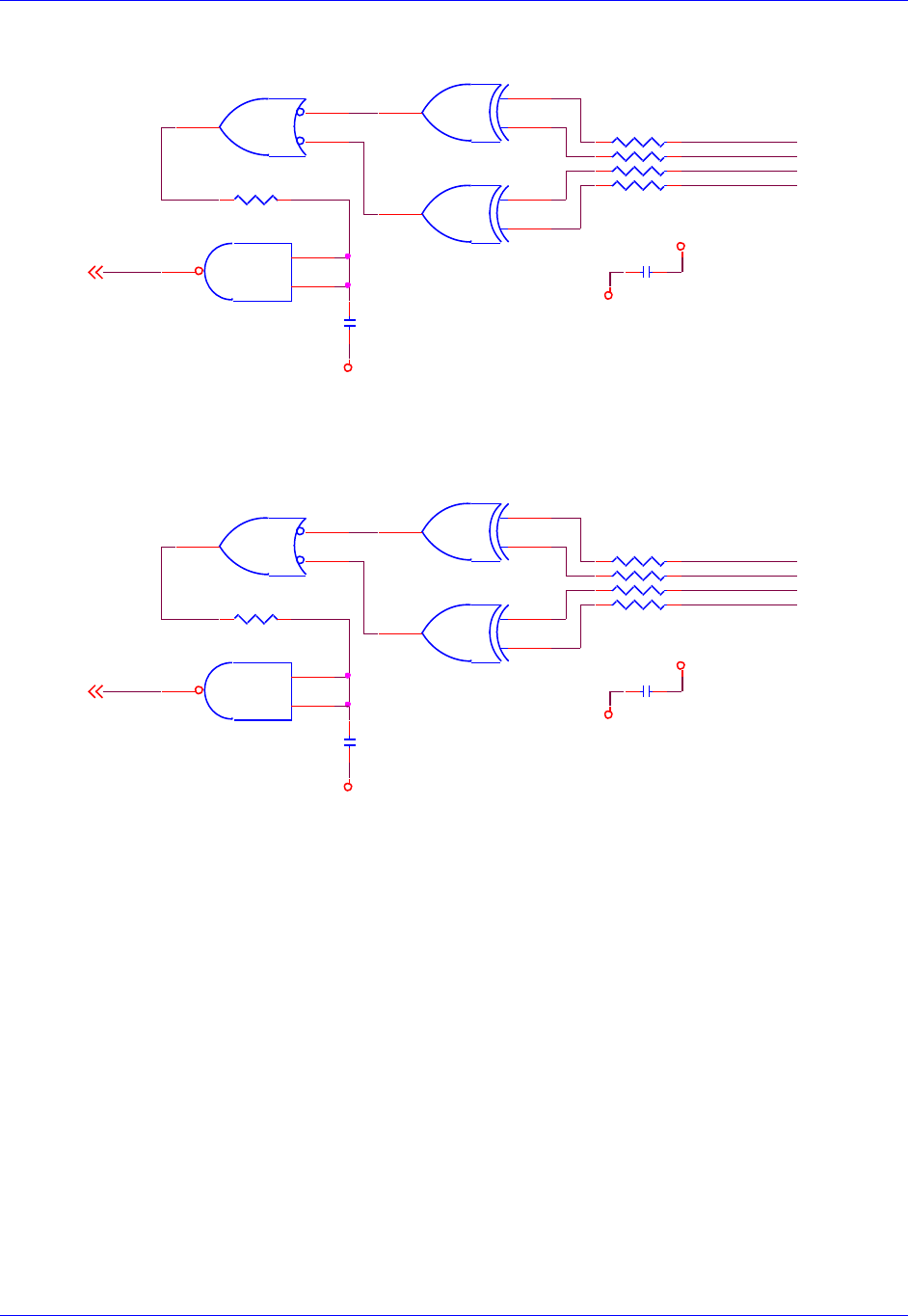
Accessory 24M2A
Appendix B: Schematics 92
Digital Quadrature Encoder Inputs
RP16
1KSIP8I
1 2
3 4
5 6
7 8
QL_1-2
QL_2-2
GND
GND
GND
GND
RP15
1KSIP8I
1 2
3 4
5 6
7 8
+5V
QL_1-
U46B
74HC132
(SO14) 4
5
6
.1uf
C129
CHB2-
U47D
74AC86
(SO14) 12
13
11
R84 2.2K
.1uf
C128
.1uf
C130
U46D
74HC132
(SO14)
12
13
11
CHA2+
U47C
74AC86
(SO14) 9
10
8
QL_2-
CHA2-
.1uf
C127
R85 2.2K
U46C
74HC132
(SO14) 9
10
8
CHB1-
CHB2+
CHB1+
U47B
74AC86
(SO14)
4
5
6
U46A
74HC132
(SO14)
1
2
3CHA1+
CHA1-
U47A
74AC86
(SO14)
1
2
3
+5V
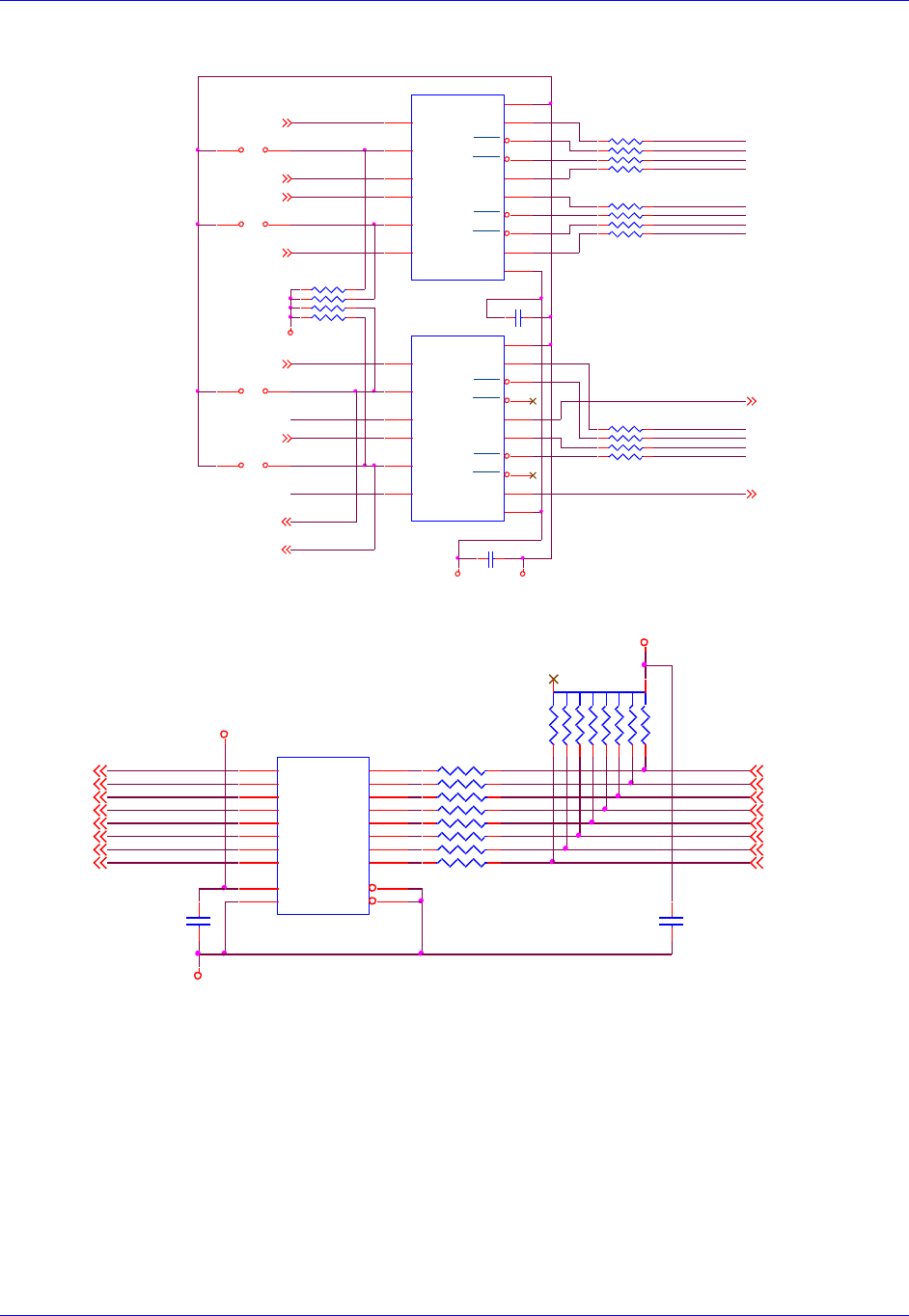
Accessory 24M2A
Appendix B: Schematics 93
Pulse and Direction Outputs
Hall Sensor Inputs
C135
.1UF
GND +5V
PWM_C_T1
C136
.1UF
PWM_C_B1
PWM_C_T2
PWM_C_B2
AENA_1
ENA_AEN1
ENC_B1 CHA1+
CHA1-AENA_2 CHA2+
CHA2-
ENA_AEN2
ENC_B2
E5 21
E6 21
FAULT_2
U50
ST34C87CF16 (SO16)
IN-A
1OUT-A 2
VCC 16
OUT-C 5
OUT-B 13
OUT-D 10
GND 8
OUT-A 3
OUT-C 6
OUT-B 14
IN-C
7
EN-A,C
4
OUT-D 11
IN-D
9
IN-B
15
EN-B,D
12
U51
ST34C87CF16 (SO16)
IN-A
1OUT-A 2
VCC 16
OUT-C 5
OUT-B 13
OUT-D 10
GND 8
OUT-A 3
OUT-C 6
OUT-B 14
IN-C
7
EN-A,C
4
OUT-D 11
IN-D
9
IN-B
15
EN-B,D
12
DIR_1+CHU1+
PUL_2+CHT2+
DIR_1-CHV1+
DIR_2-CHV2+
PUL_1+CHT1+
DIR_2+CHU2+
PUL_1-CHW1+
PUL_2-CHW2+
RP27
33SIP8I
1 2
3 4
5 6
7 8
RP26
33SIP8I
1 2
3 4
5 6
7 8
FAULT_1 2,7
FAULT_2 2,7
ENA_AEN1
7
ENA_AEN2
7
PWM_C_T12
PWM_C_B12
PWM_C_T22
PWM_C_B22
AENA_12,7
AENA_22,7
FAULT_1
RP28
33SIP8I
1 2
3 4
5 6
7 8
JUMP "E10" TO ENABLE AMP-ENA#2
JUMP "E6 2-TO-3 TO ENABLE A-B QUAD#1 OUT
JUMP "E5 2-TO-3 TO ENABLE A-B QUAD#1 OUT
JUMP "E5 1-TO-2 TO ENABLE STEPPER#1 OUT
JUMP "E6 1-TO-2 TO ENABLE STEPPER#2 OUT
JUMP "E09" TO ENABLE AMP-ENA#2
PUL-DIR OUTPUT SECTION
RP25
2.2KSIP8I
1 2
3 4
5 6
7 8
E10 21
E9 21
GND
FLAG_U12
FLAG_W12 FLAG_V12
FLAG_T12
FLAG_T22
FLAG_U22 FLAG_V22 FLAG_W22
CHU1+ 6
CHV1+ 6
CHW1+ 6
CHT1+ 6
CHU2+ 6
CHW2+ 6
CHT2+ 6
CHV2+ 6
C126
.1UF
CHV2+
CHW2+
+5V
FLAG_V2
CHT1+
FLAG_V1
GND
FLAG_U2
FLAG_W1
+5V
RP20
1KSIP8I
1 2
3 4
5 6
7 8
RP19
3.3KSIP10C
12
3
4
5
6
7
8
910
CHU1+
FLAG_W2
CHV1+
CHU2+
FLAG_U1
CHW1+
FLAG_T2
FLAG_T1
RP21
1KSIP8I
1 2
3 4
5 6
7 8 CHT2+
U45
74AC541
(SOL20)
A1 2
A2 3
A3 4
A4 5
A5 6
A6 7
A7 8
A8 9
G1 1
G2 19
Y1
18
Y2
17
Y3
16
Y4
15
Y5
14
Y6
13
Y7
12
Y8
11
VCC
20
GND
10
C125
.1UF
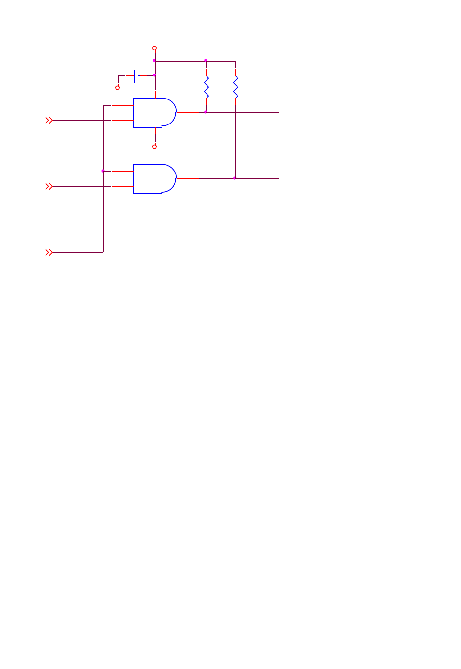
Accessory 24M2A
Appendix B: Schematics 94
Position Compare Outputs
RESET-
EQU_1
C123
.1UF
+5V
R81
330
R80
330
GND
EQU_2 BEQU2
U43A
DS75451N
(DIP8) (IN SOCKET)
1
23
84
BEQU1
GND
U43B
DS75451N
(DIP8)
(IN SOCKET)
6
75
EQU_12
EQU_22
RESET-1
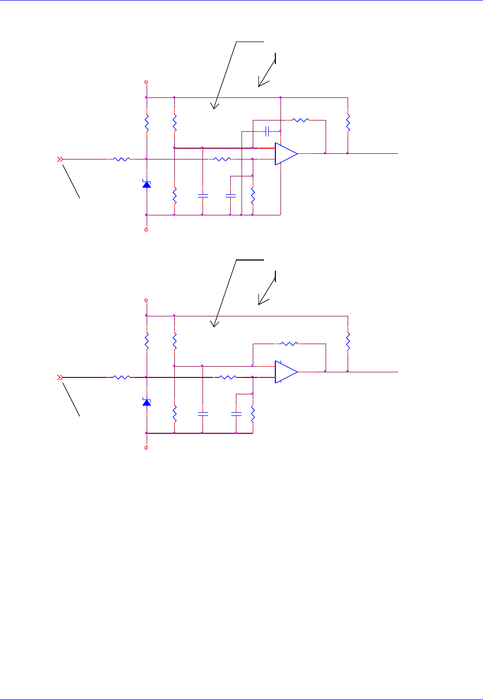
Accessory 24M2A
Appendix B: Schematics 95
Motor Thermal Inputs
C212
0.1uF
To J10 pin 23 Encoder connector
Has to be KTY84_130 and not KTY84_150
2.23 V KTY84-130 @ 130°C
Use 1.74K 1% for a 130°C allarm, 1.62K 1% for a 150°
Use 1.74K 1% for a 130°C allarm, 1.62K 1% for a 150°
Has to be KTY84_130 and not KTY84_150
2.33 V KTY84-130 @ 150°C
2.23 V KTY84-130 @ 130°C
2.33 V KTY84-130 @ 150°C
To J11 pin 23 Encoder connector
Motor Thermal
Input 1&2
Note: USE NC contact as thermal sensor. PTC resistor KTY84-130 or similar
can be used. Different PTC type needs different R82 value.
Note: USE NC contact as thermal sensor. PTC resistor KTY84-130 or similar
can be used. Different PTC type needs different R82 value.
R130
100 1%
D25
SMAJ5.0
+5VAN1
R145
7.5K 1%
R133
1.5K 1%
C213
0.1uF
R143
1.5K 1%
C216
0.1uF
R132
1.74K 1%
2_therm_mot
R144
1K 1%
D26
SMAJ5.0
1in_therm_mot6
2in_therm_mot6
1in_therm_mot
+5VAN2
2in_therm_mot
C215
0.1uF
R140
100 1%
R134
1K 1%
R136
71.5K 1%
R131
1k 1%
R146
71.5K 1%
+
-
U80A
LM393AD
(SO8)
3
21
84
R141
1k 1%
R142
1.74K 1%
1_therm_mot
C214
0.1uF
R135
7.5K 1%
+
-
U80B
LM393AD
(SO8)
5
67
R137
2.21K 1%
R147
2.21K 1%
AGND
AGND
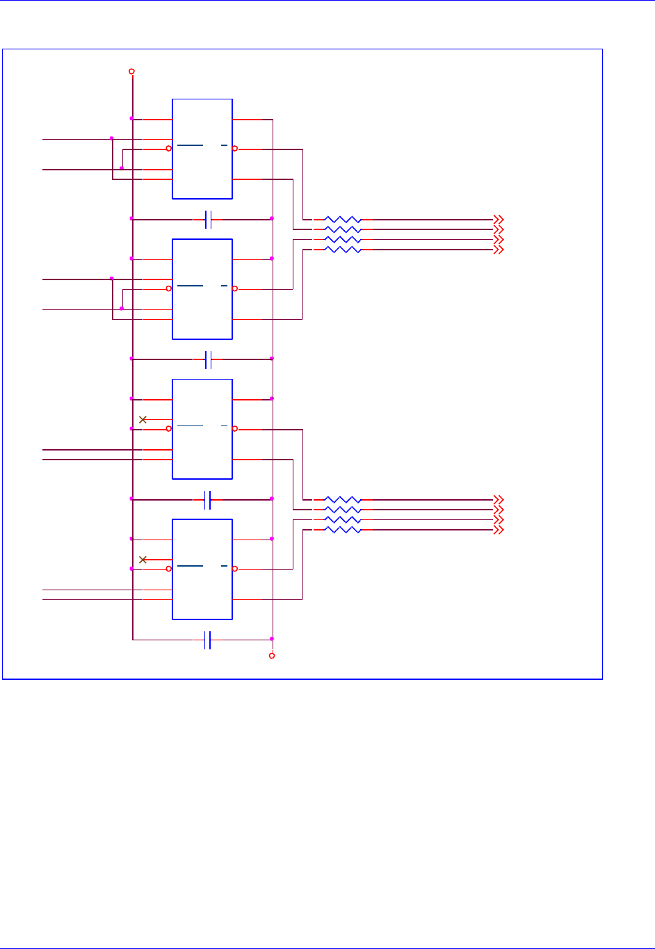
Accessory 24M2A
Appendix B: Schematics 96
SSI Inputs
C203 0.1uF
0402
12
ssi_io1+ALTCOS1+
ssi_io2+ALTCOS2+
ssi_io1-ALTCOS1-
ssi_io2-ALTCOS2-
C202 0.1uF
0402
12 RP12
33SIP8I
1 2
3 4
5 6
7 8
+5V
ssi_io1- 6
ssi_io1+ 6
ssi_io2- 6
ssi_io2+ 6
ssi_io1
ssi_io2
ena_ssi_out2
ena_ssi_out1
(SOIC8)
U85
ADM1485JR
VCC
8GND 5
ROUT
1
RENA
2
DENA
3
DIN
4A6
A7
C205 .1UF
ena_ssi_clk1
C204 .1UF
ssi_clk_out1
ena_ssi_clk2
ssi_clk_out2
(SOIC8)
U84
ADM1485JR
VCC
8GND 5
ROUT
1
RENA
2
DENA
3
DIN
4A6
A7
GND
ssi_clk_out1+ALTSIN1+
ssi_clk_out2+ALTSIN2+
ssi_clk_out1-ALTSIN1-
ssi_clk_out2-ALTSIN2-
RP13
33SIP8I
1 2
3 4
5 6
7 8 ssi_clk_out2+ 6
ssi_clk_out2- 6
ssi_clk_out1- 6
ssi_clk_out1+ 6
(SOIC8)
U83
ADM1485JR
VCC
8GND 5
ROUT
1
RENA
2
DENA
3
DIN
4A6
A7
(SOIC8)
U82
ADM1485JR
VCC
8GND 5
ROUT
1
RENA
2
DENA
3
DIN
4A6
A7
ssi
1&2
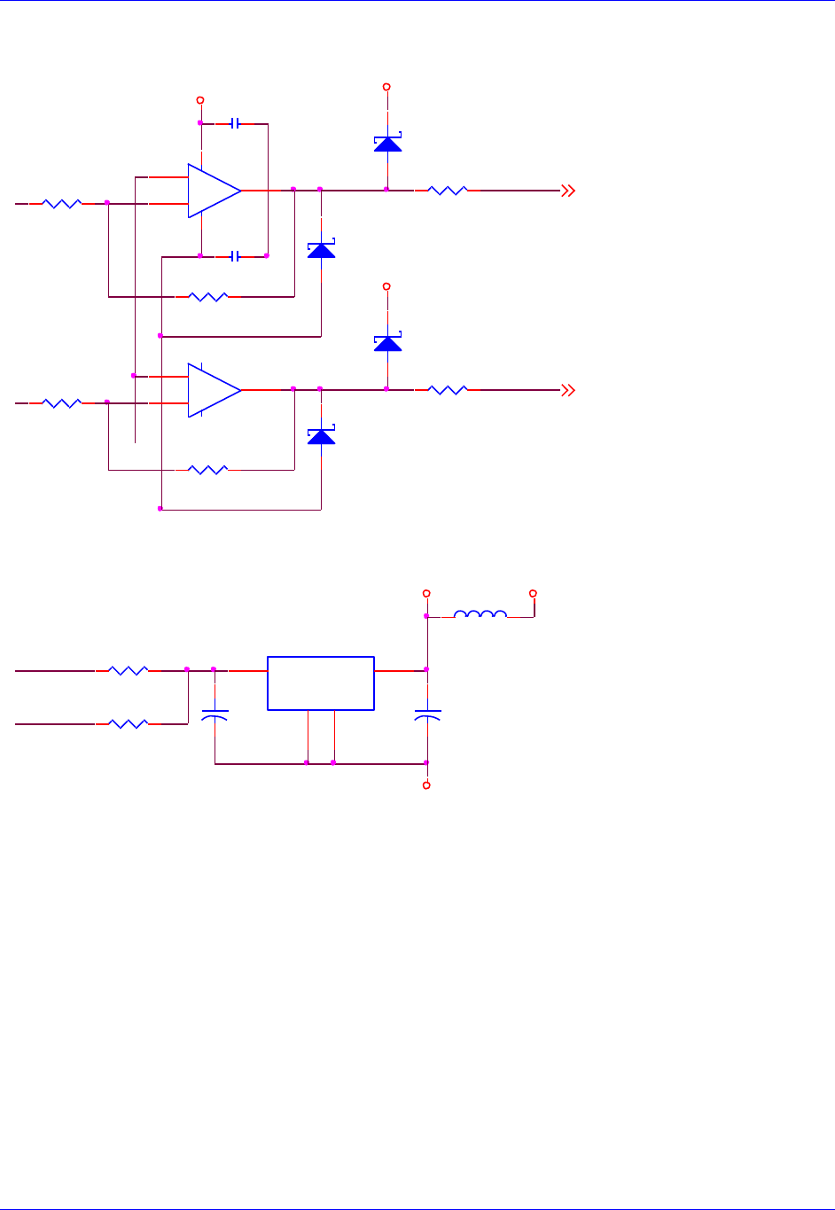
Accessory 24M2A
Appendix B: Schematics 97
Resolver Outputs
Analog Feedback Voltage Reference Circuit
+5V
R104
4.99K
R105
4.99K
R109
10ohm
R108
10ohm
.1uf
C188
R107
4.99k
+5V
R106
4.99k
.1uf
C187
+5V
D15
MMBD301LT1
1 3
ResOut1 6
ResOut2 6
D16
MMBD301LT1
1 3
D17
MMBD301LT1
1 3
D18
MMBD301LT1
1 3
ResOut2
ResOut1
+
-
U74B
lmh6672ma
5
67
+
-
U74A
lmh6672ma
3
21
84
lt1497cs8
lt1497cs8
R333 10ohm
BVREF2
BVREF1
L4 BEAD
1 2
R331 10ohm
+5V_AN +5V
U90
LT1963AEST-2.5
(SOT-223)
IN 1
OUT
3
GND
2
TAB
4
+
C249
47UF
16V
(TANT)
+
C248
47UF
16V
(TANT)
AGND
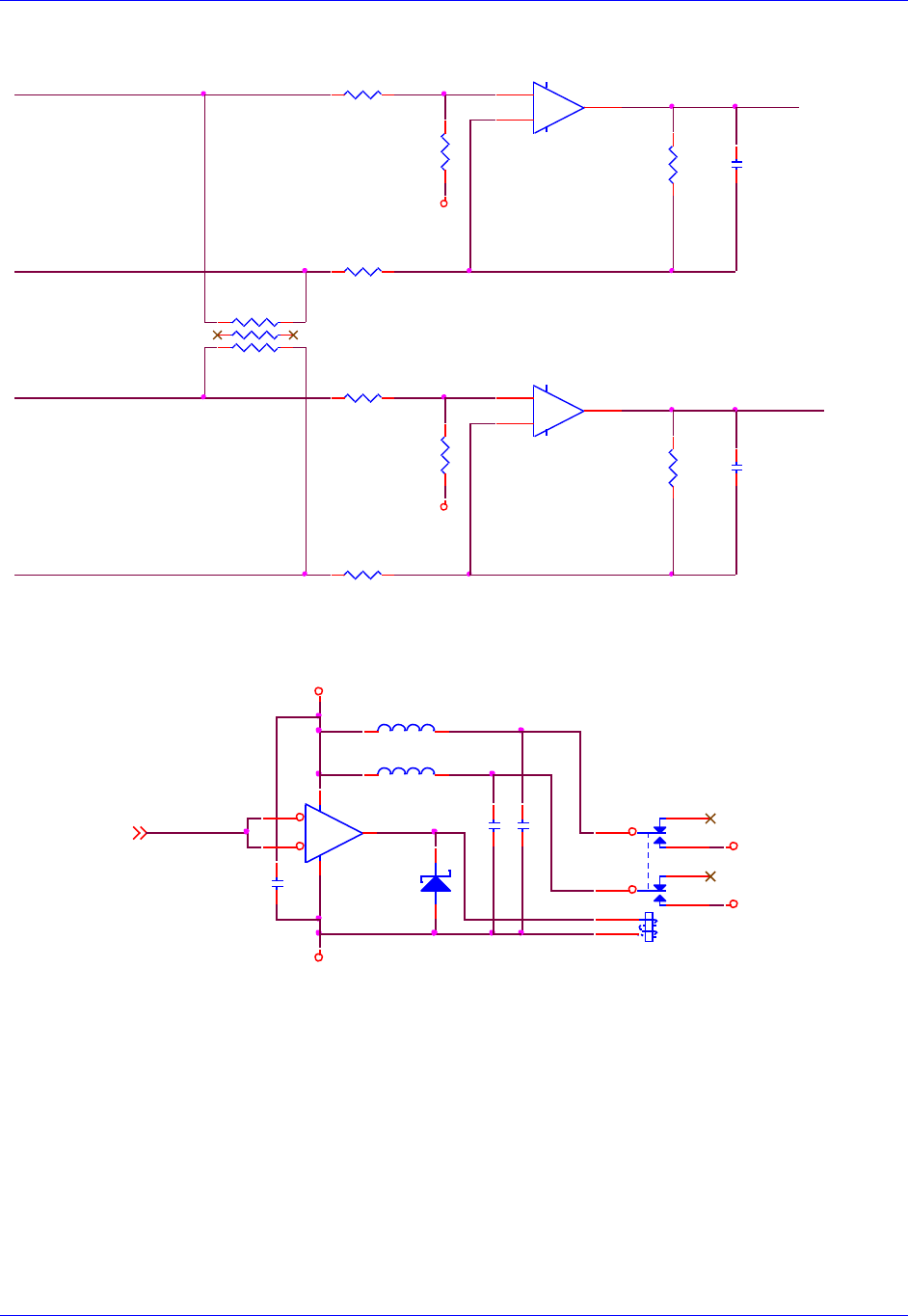
Accessory 24M2A
Appendix B: Schematics 98
Sin/Cos Inputs
Note: Sin/Cos inputs for Channel #2 are identical to Channel #1.
Encoder Power
+
-
U91B
AD824AR
(SO14)
5
67
+
-
U91C
AD824AR
(SO14)
10
98
ALTCOS1+ ssi_io1+
ALTSIN1- ssi_clk_out1-
ALTCOS1- ssi_io1-
R231 12.7K
R235
27.4K R237
27.4K
R232 12.7K
AGND
R230 12.7K
ALTSIN1+ ssi_clk_out1+
22pf
C243
R234
27.4K
RP62
220SIP6I
1 2
3 4
5 6
22pf
C244
R236
27.4K
SOCKET
R233 12.7K
AGND
D34
MMBD301LT1
1 3
GND
enc_pwr_1_25
+5V
L6
BEAD
1 2
EncPwr2
EncPwr1
enc_pwr_1_2
L5
BEAD
1 2
U99
NC7SZ14M5
(SOT23-5)
4
3 5
1
2
.1uf
C266
K1
FBR12ND05
43
5
910
8
1
12
.1uf
C267
.1uf
C268
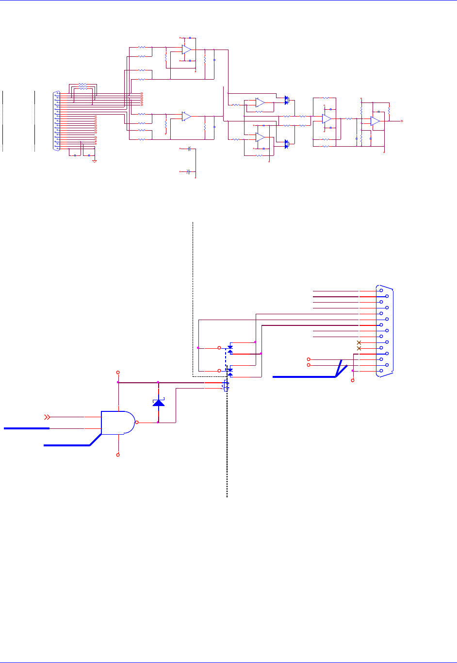
Accessory 24M2A
Appendix B: Schematics 99
Sinusoidal Encoder Input
Note: Encoder #2 is identical to Encoder #1.
Amplifier Output
Note: Amplifier Output #2 is identical to Amplifier Output #1.
R190
150.0K
.1uf
C238
LOS_1- 2
R194
30.9K
CHA1+ 2
R186
24.9K
CHA1- 2
.1uf
C240
CHB1+ 2
CHB1- 2
R191
150.0K
R193
10.0K
R196
3.01K
CHC1+ 2
CHC1- 2 R182
27.4K
.1uf
C241
+5VAN1
-5VAN1
.1uf
C239
R189
10.0K
D31
MMBD4148CC
1
23
R184
27.4K
.1uf
C236
CHV1+ 2
CHU1+ 2
CHT1+ 2
CHW1+ 2
1in_therm_m ot
R171 12.7K
R172 12.7K
R175 12.7K
R176 12.7K
ALTCOS1- ssi_io1-
Sin1+ CHA1+
AGND
Sin1- CHA1-
ResC os1+
BVREF1
ResC os1-
ResOut 1
+5VAN1
index1+ CH C1+
B VR E F1
RESOLVER
E N C P W R 1
C O S1 +
DAT1+/ALTCOS1+
22pf
C234
ALTSIN1+ ss i_clk_out 1+
index1- CH C1-
R170 12.7K
CHT1+/PUL_1-
.1uf
C232
+ 5 V
R180
27.4K
ENCODER 1
C O S1 -
R es Co s 1 -
-5VAN1
CHV1+/DIR_1-
R es Sin 1 -
R es Sin 1 +
.1uf
C230
ALTSIN1- ss i_clk_out 1-
.1uf
C231
ResSin1-
CHU1+
CHW1+
CHV1+
CHU1+/DIR_1+
SI N 1 -
SINUSOIDAL
RP60
220SIP6I
1 2
3 4
5 6
Cos1- C HB1-
I N D E X 1 +
INPUT #1 R181
27.4K
GN D
SI N 1 +
R es O ut 1
ENCODER /
R177 12.7K
I N D E X 1 -
R es Co s 1 +
CHT1+
R179
27.4K 22pf
C235
J11
DB25S
13
25
12
24
11
23
10
22
9
21
8
20
7
19
6
18
5
17
4
16
3
15
2
14
1
CLK1+/ALTSIN1+
+
-
U98A
LM393AD
(SO8)
3
21
84
EncPwr1
CLK1-/ALTSIN1- ALTCOS1+ ssi_io1+
ResSin1+
DAT1-/ALTCOS1-
Cos1+ C HB1+
R178
27.4K
SIN INPUT
CHW1+/PUL_1+
AGND
SOCKET
GN D
COS INPUT
R174 12.7K
ssi_io1+ 5
ssi_io1- 5
AGND
1 in _ t h e r m _ m o t
ß=2.15
ssi_clk_out1+ 5
ssi_clk_out1- 5
+5V
.1uf
C237
R187
24.9K
AGND
+
-
U91A
AD824AR
(SO14)
3
21
411
+
-
U97A
AD822AR
(SO8)
3
21
84
-5VAN1
+
-
U91D
AD824AR
(SO14)
12
13 14
LOS_1-
.1uf
C233
R185
27.4K
+
C269
10uf
25V_tant
+5VAN1
+
-
U95B
AD822AR
(SO8)
5
67
+
C270
10uf
25V_tant
-5VAN1
+
-
U95A
AD822AR
(SO8)
3
21
84
ResOut 1 5
AGND
R173 12.7K
R183
27.4K
+5VAN1
1in_therm_m ot 5
+5VAN1
R188
10.0K
D30
MMBD4148CC
1
23
R195
4.99K
R192
10.0K
.01uf
C242
AENA_1
+5V
GND
K3
FBR12ND05
43
5
910
8
1
12
"AGND" PLANE"DGND" PLANE
AGND
AGND
**NEW POWER SIGNAL**
AMP-OUT 1
AGND
N.C.
A+12V
A-12V
N.C.
DAC1_B-
DAC1_A-
DAC1_A+
DAC1_B+
DAC1_A+
DACENA
AFAULT_1+
AFAULT_1-
DAC1_B+
AE_COM_1
AE_NC_1
DAC1_B-
DAC1_A-
AE_NO_1
U119
NC7SZ00
(SOT23-5)
1
24
53
**NETLIST CHANGE**
**PART CHANGE**
AE_NC_1
AE_COM_1
AE_NO_1
AFAULT_1+
AFAULT_1-
D42
MMBD301LT1
1 3
A+12V
A--12V
AENA_12,4
A+12V
A--12V
J1
DB15S
8
15
7
14
6
13
5
12
4
11
3
10
2
9
1
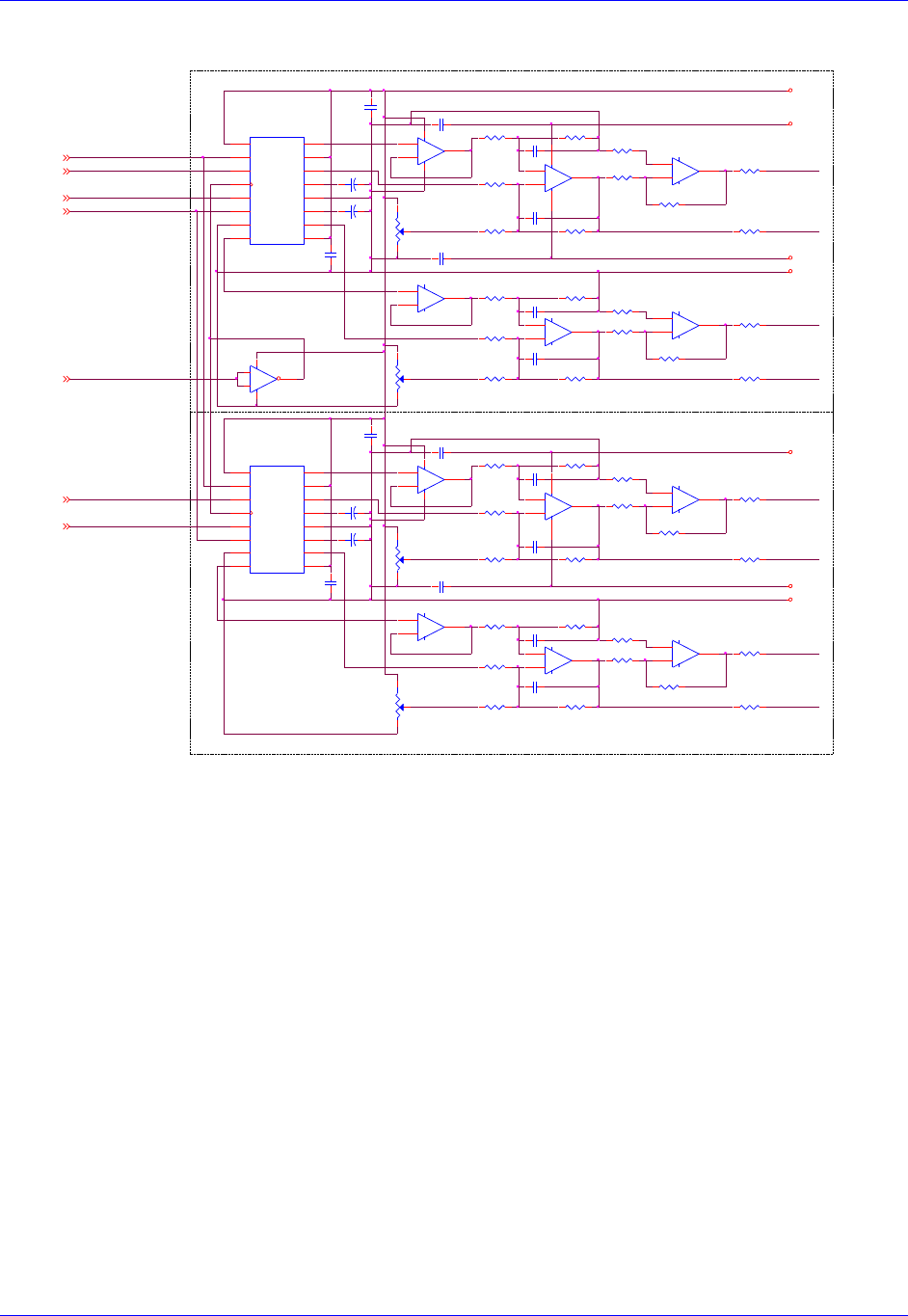
Accessory 24M2A
Appendix B: Schematics 100
DAC Outputs
+
-
U115B
LF347M
(SO14)
5
67
OFFSET
U111
AD1868R
(SOL16)
VL
1
LL
2
DL
3
CK
4
DR
5
LR
6
DGND
7
VBR
8VS 9
VOR 10
NRR 11
AGND 12
NRL 13
VOL 14
VS 15
VBL 16
+
-
U115C
LF347M
(SO14)
10
98
OUTPUT
+
-
U115D
LF347M
(SO14)
12
13 14
POT
POT
C297
C298
C290
.1UF
C291
.1UF
R254
5K POT
RP66B
2.2KSIP8I 1%
3 4
RP66A
2.2KSIP8I 1%
1 2
C299
C300
R256
5K POT
RP72C
220SIP8I
5 6
RP66D
2.2KSIP8I 1%
7 8
RP66C
2.2KSIP8I 1%
5 6
RP72B
220SIP8I
3 4
RP72A
220SIP8I
1 2
RP72D
220SIP8I
7 8
OUTPUT
POT
DAC2_B+
OFFSET
R250
5K POT
SA+12V
AGND
AGND
A+5V
SA-12V
SA-12V
SA+12V
"AGND" PLANE
"AGND" PLANE
DAC1_A+
DAC1_A-
DAC2_A+
DAC1_B-
DAC2_A-
DAC1_B+
RP67B
22KSIP8I 1%
3 4
RP67C
22KSIP8I 1%
5 6
RP67D
22KSIP8I 1%
7 8
RP68A
22KSIP8I 1%
1 2
R259
11.00K 1%
OUTPUT
RP68D
22KSIP8I 1%
7 8
R268
11.00K 1%
R269
11.00K 1%
RP68B
22KSIP8I 1%
3 4
RP68C
22KSIP8I 1%
5 6
RP69A
22KSIP8I 1%
1 2
RP69B
22KSIP8I 1%
3 4
RP69C
22KSIP8I 1%
5 6
RP69D
22KSIP8I 1%
7 8
RP70A
22KSIP8I 1%
1 2
RP70D
22KSIP8I 1%
7 8
RP70B
22KSIP8I 1%
3 4
RP70C
22KSIP8I 1%
5 6
+
-
U114D
LF347M
(SO14)
12
13 14
+
-
U114C
LF347M
(SO14)
10
98
U116
NC7SZ14M5
(SOT23-5)
4
3 5
1
2
+
-
U114B
LF347M
(SO14)
5
67
OFFSET
R253
100K 1%
R255
100K 1%
R257
100K 1%
R258
11.00K 1%
+
-
U112A
AD822AR
(SO8)
3
21
84
R252
5K POT
DACB_DAT2PWM_B_B2
DACA_DAT2PWM_A_B2
DACA_DAT1PWM_A_B1
DACB_DAT1PWM_B_B1
DAC_CLK1PWM_A_T1
DAC_STB1PWM_B_T1
DAC_STB2PWM_B_T2
PWM_B_T12
PWM_A_B12
PWM_A_B22
PWM_B_T22
PWM_B_B12
PWM_A_T12
PWM_B_B22 OUTPUT
POT
OFFSET
+
-
U112B
AD822AR
(SO8)
5
67
+
-
U113A
AD822AR
(SO8)
3
21
84
RP65D
2.2KSIP8I 1%
7 8
RP65C
2.2KSIP8I 1%
5 6
RP65B
2.2KSIP8I 1%
3 4
RP65A
2.2KSIP8I 1%
1 2 RP67A
22KSIP8I 1%
1 2
+
-
U114A
LF347M
(SO14)
3
21
411
R251
100K 1%
C281
.1UF
+
C282
4.7UF
+
C283
4.7UF
C280
.1UF
DAC2_B-
C285
.1UF
+
C286
4.7UF
+
C287
4.7UF
C284
.1UF
C296
C295
C289
.1UF
C294
C293
C288
.1UF
RP71C
220SIP8I
5 6
RP71B
220SIP8I
3 4
RP71A
220SIP8I
1 2
RP71D
220SIP8I
7 8
U110
AD1868R
(SOL16)
VL
1
LL
2
DL
3
CK
4
DR
5
LR
6
DGND
7
VBR
8VS 9
VOR 10
NRR 11
AGND 12
NRL 13
VOL 14
VS 15
VBL 16
+
-
U113B
AD822AR
(SO8)
5
67
+
-
U115A
LF347M
(SO14)
3
21
411
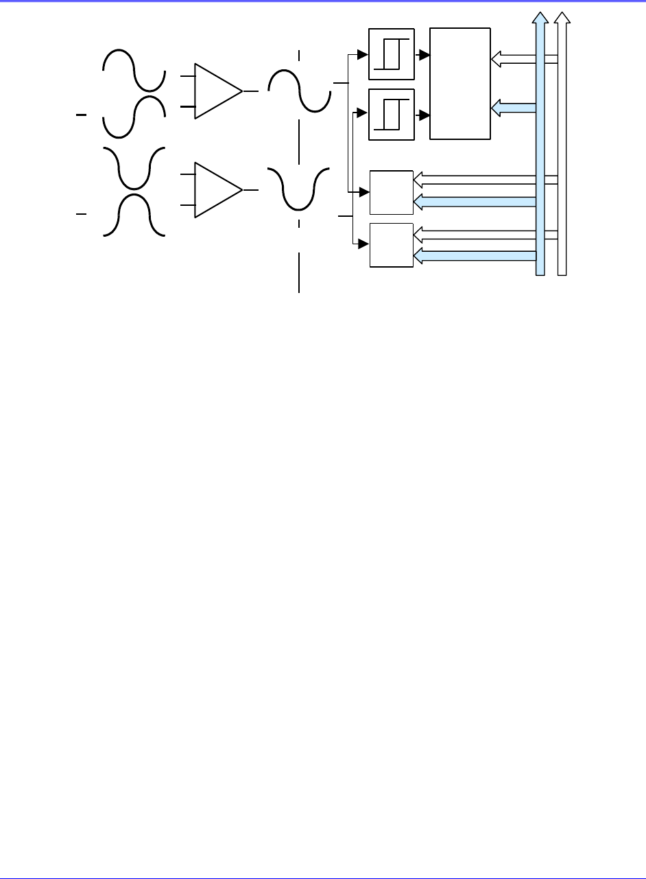
Appendix C: Sinusoidal Interpolation 101
APPENDIX C: SINUSOIDAL INTERPOLATION
Analog
Photo
Current
A
A
B
B
Encoder Controller
Differential
Amplifier
Sin / Cos
Signals
Comparator
1 - Bit A/D
n-bit
A/D
n-bit
A/D
Decoder /
Counter
The sine and cosine signals from the encoder are processed in two ways in this product (see above
diagram). First, they are sent through comparators that square up the signals into digital quadrature and
are then sent into the quadrature decoding and counting circuit of the Servo IC on the ACC-24M2A. The
units of the hardware counter, which are called hardware counts, are thus ¼ of a line. For most users, this
fact is an intermediate value, an internal detail that does not concern them. However, this is important in
two cases. First, if the sinusoidal encoder is used for PMAC-based brushless-motor commutation, the
hardware counter (not the fully interpolated position value) will be used for the commutation position
feedback. Therefore, the units of Ixx71 will be hardware counts. Second, if the hardware position-
compare circuits in the Servo IC are used, the units of the compare register are hardware counts. The
same is true of the hardware position-capture circuits, but often these scaling issues are handled
automatically through the move-until-trigger constructs.
The second, parallel processing of the sine and cosine signals is through analog-to-digital converters,
which produce numbers proportional to the input voltages. These numbers are used to calculate
mathematically an arctangent value that represents the location within a single line. This is calculated to
1/4096th of a line, so there are 4096 unique states per line, or 1024 states per hardware count.
For historical reasons, PMAC expects the position it reads for its servo feedback software to have units of
1/32th of a count. That is, PMAC considers the least significant bit (LSB) of whatever it reads for position
feedback to have a magnitude of 1/32th of a count for the purposes of its software scaling calculations.
We call the resulting software units software counts and any software parameter that uses counts from the
servo feedback (e.g. jog speed in counts/msec, axis scale factor in counts/engineering-unit) is using these
software counts. In most cases, such as digital quadrature feedback, these software counts are equivalent
to hardware counts.
However, with the added resolution produced by the ACC-24M2A interpolator option, software counts
and hardware counts are no longer the same. The LSB produced by the interpolator (through the encoder
conversion table processing) is 1/1024th of a hardware count, but PMAC software considers it 1/32th of a
software count. Therefore, with the ACC-24M2A, a software count is 1/32th the size of a hardware count.
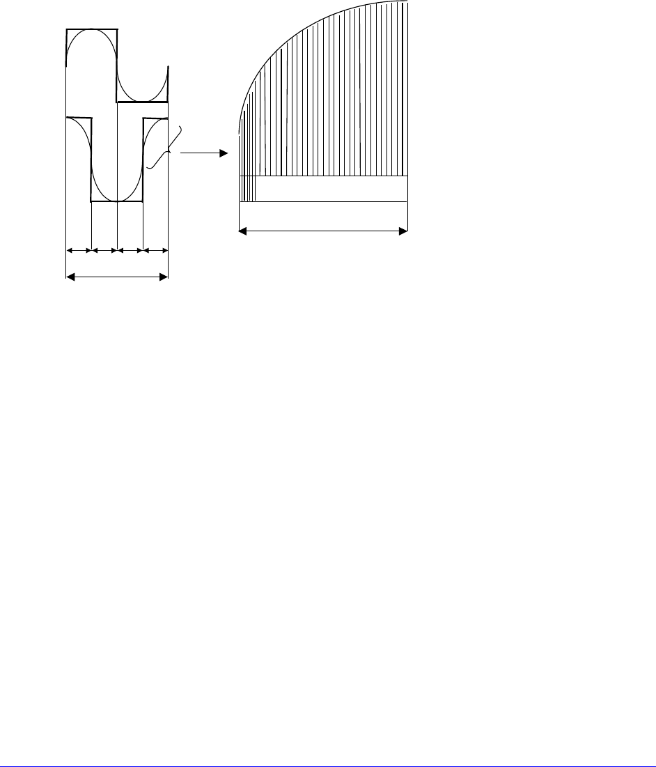
Appendix C: Sinusoidal Interpolation 102
The following equations express the relationships between the different units:
1 line = 4 hardware counts = 128 software counts = 4096 states (LSBs)
¼-line = 1 hardware count = 32 software counts = 1024 states (LSBs)
1/128-line = 1/32-hardware count = 1 software count = 32 states (LSBs)
1/4096-line = 1/1024-hardware count = 1/32-software count = 1 state (LSB)
Note that these are all just naming conventions. Even the position data that is fractional in terms of
software counts is real. The servo loop can see it and react to it, and the trajectory generator can
command to it.
Four hardware counts per line
128 whole software counts and 3 bits
of fractional counts (1024 states)
One hardware count
The Interpolator can accept a voltage-source (1 Vpp) signal from the encoder. The maximum sine-cycle
frequency input is approximately 8 MHz (1,400,000 SIN cycles/sec), which gives a maximum speed of
about 5.734 billion steps per second.
When used with a 1000 line sinusoidal rotary encoder, there will be 4,096,000 discrete states per
revolution (128,000 software counts). The maximum calculated electrical speed of this encoder would be
1,400 RPS or 84,000 RPM, which exceeds the maximum physical speed of most encoders.
Example 1:
A 4-pole rotary brushless motor has a sinusoidal encoder with 2000 lines. It directly drives a screw with a
5-mm pitch.
For servo control, the interpolated results of the conversion table are used. There are 128 software counts
per line, or 256,000 software counts per revolution. With each revolution corresponding to 5 mm on the
screw, there are 51,200 software counts per millimeter. The measurement resolution, at 4096 states per
line, is 1/8,192,000 of a revolution, or 1/1,638,400 of a millimeter (~0.6 nanometers/state).
Example 2:
A linear brushless motor has a commutation cycle of 60.96 mm (2.4 inches). It has a linear scale with a
20-micron line pitch.
The servo uses the interpolated results of the conversion table. With 128 software counts per line, and 50
lines per millimeter, there are 6400 software counts per millimeter (or 162,560 software counts per inch).
The measurement resolution, at 4096 states per line, is 204,800 states per mm (~5 nanometers/state).
