Deltanode Solutions DDH1900 43dBm High Power Remote User Manual Fiber Distributed Antenna System DAS
Deltanode Solutions AB 43dBm High Power Remote Fiber Distributed Antenna System DAS
Contents
- 1. User Manual_Part 1
- 2. User Manual_Part 2
User Manual_Part 1

Fiber Distributed Antenna System
(Fiber DAS)
Operation Manual
©
Copyright 2017
by Bird Technologies, Inc.
Instruction Book Part Number 920-Fiber-DAS Rev. P3
Delta Node® is a registered trademark of Delta Node Solutions Ltd. and Bird Technologies, Inc.

i
Safety Precautions
Thefollowingaregeneralsafetyprecautionsthatarenotnecessarilyrelatedtoanyspecificpartorprocedure,and
donotnecessarilyappearelsewhereinthispublication.Theseprecautionsmustbethoroughlyunderstoodand
applytoallphasesofoperationandmaintenance.
WARNING
KeepAwayFromLiveCircuits
OperatingPersonnelmustatalltimesobservegeneralsafetyprecautions.Donotreplacecomponentsormake
adjustmentstotheinsideofthetestequipmentwiththehighvoltagesupplyturnedon.Toavoidcasualties,
alwaysremovepower.
WARNING
ShockHazard
DonotattempttoremovetheRFtransmissionlinewhileRFpowerispresent.
WARNING
DoNotServiceOrAdjustAlone
Undernocircumstancesshouldanypersonreachintoanenclosureforthepurposeofserviceoradjustmentof
equipmentexceptinthepresenceofsomeonewhoiscapableofrenderingaid.
WARNING
SafetyEarthGround
Anuninterruptibleearthsafetygroundmustbesuppliedfromthemainpowersourcetotestinstruments.
Groundingoneconductorofatwoconductorpowercableisnotsufficientprotection.Seriousinjuryordeathcan
occurifthisgroundingisnotproperlysupplied.
WARNING
Resuscitation
Personnelworkingwithornearhighvoltagesshouldbefamiliarwithmodernmethodsofresuscitation.
WARNING
RemovePower
Observegeneralsafetyprecautions.Donotopentheinstrumentwiththepowerapplied.
SafetyPrecautions
ii
Safety Symbols
Note:
ThelaserusedinthissystemisaClass3blaserthatproducesinvisibleinfra‐redcoherent
light.Avoidlookingintoconnectedfibersandreceptacles.Notsafetoviewwithoptical
instruments.Alwaysputtheprotectioncapsonunusedfibersandreceptacles.
Callsattentiontosupplementalinformation.
WARNING
Warningnotescallattentiontoaprocedure,whichifnotcorrectlyperformed,couldresultinpersonalinjury.
CAUTION
Cautionnotescallattentiontoaprocedure,whichifnotcorrectlyperformed,couldresultindamagetothe
instrument.

FiberDistributedAntennaSystem(FiberDAS)
iii
Warning Statements
Thefollowingsafetywarningsappearinthetextwherethereisdangertooperatingandmaintenancepersonneland
arerepeatedhereforemphasis.
See
page40
ForCMRS817‐824MHzApplicationsandAmericanCellularApplications:
See
page40
See
page40
See
page15
WARNING
ThisisNOTaconsumerdevice.
ItisdesignforinstallationbyFCCLICENSEESandQUALIFIEDINSTALLERS.YouMUSThaveanFCCLICENSEor
expressconsentofanFCClicenseetooperatethisdevice.YouMUSTregisterClassBsignalboosters(asdefinedin
47CFR90.219)onlineatwww.fcc.gov/signal‐boosters/registration.Unauthorizedusemayresultin
significantforfeiturepenalties,includingpenaltiesinexcessof$100,000foreachcontinuingviolation.
WARNING
ThisisNOTaconsumerdevice.
ItisdesignforinstallationbyFCCLICENSEESandQUALIFIEDINSTALLERS.YouMUSThaveanFCCLICENSEor
expressconsentofanFCClicenseetooperatethisdevice.Unauthorizedusemayresultinsignificantforfeiture
penalties,includingpenaltiesinexcessof$100,000foreachcontinuingviolation.
WARNING
ThisisNOTaconsumerdevice.
ItisdesignedforinstallationbyaninstallerapprovedbyanISEDlicensee.
YouMUSThaveanISEDLICENCEortheexpressconsentofanISEDlicenseetooperatethisdevice.
WARNING
Avoidlookingintoconnectedfibersandreceptacles.
ThelaserusedinthissystemisaClass3blaserthatproducesinvisibleinfra‐redcoherentlight.Notsafetoview
withopticalinstruments.Alwaysputtheprotectioncapsonunusedfibersandreceptacles.

SafetyPrecautions
iv
Caution Statements
Thefollowingequipmentcautionsappearinthetextandarerepeatedhereforemphasis.
See
page114
See
page41
.
See
page47
CAUTION
TurnOffTestTone
Donotforgettoturnoffthetesttonewhenyouaredonewithyouruplink.Bettercheckoneextratime.Theywill
otherwiseinterferewiththenormaloperationofthesystembycausingnoisetothebasestation.
CAUTION
Unauthorizedantennas,cables,and/orcouplingdevicesmaycausenon‐conformitywithnationalorinternational
regulations,couldcausedamage,ornon‐conformingERP/EIRP.
CAUTION
WhenmatingRFconnectors,ensurethattheyareproperlyalignedandnotcrossthreaded.
TightenSMAconnectorsto8in.‐lbs.
DoovertorqueRFconnectors,thiscouldresultindamagetotheUnit.
DonotundertorqueRFconnectors,thiscouldresultinpoorsignaltransmission.

FiberDistributedAntennaSystem(FiberDAS)
v
Safety Statements
USAGE
ANY USE OF THIS INSTRUMENT IN A MANNER NOT SPECIFIED BY THE MANUFACTURER MAY
IMPAIR THE INSTRUMENT’S SAFETY PROTECTION.
USO
EL USO DE ESTE INSTRUMENTO DE MANERA NO ESPECIFICADA POR EL FABRICANTE, PUEDE
ANULAR LA PROTECCIÓN DE SEGURIDAD DEL INSTRUMENTO.
BENUTZUNG
WIRD DAS GERÄT AUF ANDERE WEISE VERWENDET ALS VOM HERSTELLER BESCHRIEBEN,
KANN DIE GERÄTESICHERHEIT BEEINTRÄCHTIGT WERDEN.
UTILISATION
TOUTE UTILISATION DE CET INSTRUMENT QUI N’EST PAS EXPLICITEMENT PRÉVUE PAR LE
FABRICANT PEUT ENDOMMAGER LE DISPOSITIF DE PROTECTION DE L’INSTRUMENT.
IMPIEGO
QUALORA QUESTO STRUMENTO VENISSE UTILIZZATO IN MODO DIVERSO DA COME
SPECIFICATO DAL PRODUTTORE LA PROZIONE DI SICUREZZA POTREBBE VENIRNE
COMPROMESSA.

SafetyPrecautions
vi
SERVICE
SERVICING INSTRUCTIONS ARE FOR USE BY SERVICE - TRAINED PERSONNEL ONLY. TO AVOID
DANGEROUS ELECTRIC SHOCK, DO NOT PERFORM ANY SERVICING UNLESS QUALIFIED TO DO
SO.
SERVICIO
LAS INSTRUCCIONES DE SERVICIO SON PARA USO EXCLUSIVO DEL PERSONAL DE SERVICIO
CAPACITADO. PARA EVITAR EL PELIGRO DE DESCARGAS ELÉCTRICAS, NO REALICE NINGÚN
SERVICIO A MENOS QUE ESTÉ CAPACITADO PARA HACERIO.
WARTUNG
ANWEISUNGEN FÜR DIE WARTUNG DES GERÄTES GELTEN NUR FÜR GESCHULTES
FACHPERSONAL.
ZUR VERMEIDUNG GEFÄHRLICHE, ELEKTRISCHE SCHOCKS, SIND WARTUNGSARBEITEN
AUSSCHLIEßLICH VON QUALIFIZIERTEM SERVICEPERSONAL DURCHZUFÜHREN.
ENTRENTIEN
L’EMPLOI DES INSTRUCTIONS D’ENTRETIEN DOIT ÊTRE RÉSERVÉ AU PERSONNEL FORMÉ AUX
OPÉRATIONS D’ENTRETIEN. POUR PRÉVENIR UN CHOC ÉLECTRIQUE DANGEREUX, NE PAS
EFFECTUER D’ENTRETIEN SI L’ON N’A PAS ÉTÉ QUALIFIÉ POUR CE FAIRE.
ASSISTENZA TECNICA
LE ISTRUZIONI RELATIVE ALL’ASSISTENZA SONO PREVISTE ESCLUSIVAMENTE PER IL
PERSONALE OPPORTUNAMENTE ADDESTRATO. PER EVITARE PERICOLOSE SCOSSE
ELETTRICHE NON EFFETTUARRE ALCUNA RIPARAZIONE A MENO CHE QUALIFICATI A FARLA.

FiberDistributedAntennaSystem(FiberDAS)
vii
About This Manual
Thismanualcoverstheoperating&maintenanceinstructionsforthefollowingmodels:
Changes to this Manual
Wehavemadeeveryefforttoensurethismanualisaccurate.Ifyoudiscoveranyerrors,orifyouhavesuggestions
forimprovingthismanual,pleasesendyourcommentstoourSolon,Ohiofactory.Thismanualmaybeperiodically
updated.Wheninquiringaboutupdatestothismanualrefertothepartnumber:920‐Fiber‐DAS;andrevision:P3.
Chapter Layout
Introduction — DescribesthefundamentalsoftheBirdFiber‐DASandprovidesalistofcommonlyused
abbreviationsandacronyms.
System Description — DescribestheMajorcomponentsthatmakeupaBirdFiber‐DASsystem.
Installation Guidelines — ProvidesFCCrequirementsandsafetyconsiderationswheninstallingaBirdFiber‐DAS.
Commissioning — ListsthepreparationsandequipmentrequiredtosuccessfullyinstallandcommissiontheBird
Fiber‐DAS.
RF Commissioning — Chaptercontainsusefuladviceonhowtodesignawellworkingsystemaswellas
examplesforfinetuninglinkabudgetandcontrollingnoiseinaBirdFiber‐DAS.
Model Identification — ProvidesabreakdownoftheBirdpartnumbersfortheFiber‐DASsystems.Atableof
partnumbersusedforRemoteUnitsisalsoprovided.
Fiber‐DAS
viii
Table of Contents
SafetySymbols................................................................................ii
WarningStatements...........................................................................iii
CautionStatements............................................................................iv
SafetyStatements..............................................................................v
ChangestothisManual........................................................................vii
ChapterLayout...............................................................................vii
Chapter 1 Introduction . . . . . . . . . . . . . . . . . . . . . . . . . . . . . . . . . . . . . . . . . . . . . . . . . . . . . . . . . . . . . . . 1
RFonfiber....................................................................................1
Definitions....................................................................................2
Chapter 2 System Description. . . . . . . . . . . . . . . . . . . . . . . . . . . . . . . . . . . . . . . . . . . . . . . . . . . . . . . . . 4
Gateways.....................................................................................4
CentralGateway(CGW)......................................................................4
BaseStationGateway(BGW).................................................................4
RemoteGateway(RGW).....................................................................6
Headend.....................................................................................6
DCS‐NetworkSwitch........................................................................6
MasterFrameUnit(MFU)....................................................................7
BaseStationInterfaceUnit(BIU)...............................................................8
InterconnectUnit(ICU).....................................................................1
3
FiberOpticInterface(FOI)unit...............................................................1
5
PSU–therackpowersupply.................................................................2
0
RemoteUnit(RU).............................................................................2
1
DDR.....................................................................................2
2
DDS.....................................................................................2
6
DDH.....................................................................................2
8
DDU.....................................................................................3
1
RemoteUnitFrequencySummary............................................................3
2
DMU–Remoteheadend...................................................................3
3
Repeaters...................................................................................3
4
DMR400SeriesRackMountRepeater.........................................................3
4
DLR600SeriesLowPowerRepeater..........................................................3
6
DMR600SeriesMediumPowerRepeater......................................................37
DHR800SeriesHighPowerRepeater..........................................................3
8
BirdRepeaterFrequencySummary...........................................................3
9
Chapter 3 Installation guidelines . . . . . . . . . . . . . . . . . . . . . . . . . . . . . . . . . . . . . . . . . . . . . . . . . . . . . 40
HealthandSafety.............................................................................4
0
CableRouting/AntennaSelection................................................................4
1
AntennaInstallation........................................................................4
1
SafetyandCareforFibers......................................................................41
ToolsandMaterialRequirements................................................................4
2
FiberOptics...............................................................................4
2
Tools....................................................................................4
2
MiscellaneousMaterial.....................................................................4
2
InstallingHeadendEquipment..................................................................4
3
BGW.....................................................................................4
3
EthernetSwitch...........................................................................4
3
MasterUnit...............................................................................4
4

FiberDistributedAntennaSystem(FiberDAS)
ix
PowerSupplyUnit.........................................................................4
5
BIU......................................................................................4
7
ICU......................................................................................4
8
FOI......................................................................................4
8
RFU.....................................................................................4
9
PoweringUptheHeadEnd.....................................................................4
9
InstallingRemoteUnits........................................................................5
0
SingleRemoteUnitWallMounting...........................................................5
0
DoubleRemoteUnitWallMounting..........................................................5
1
RemoteUnitPoleMounting.................................................................5
1
SolarShield...............................................................................5
2
Cabling...................................................................................5
2
RemoteUnitVerification....................................................................5
5
InstallingtheDHRRepeater....................................................................5
6
SingleRepeaterWallMounting..............................................................5
6
DoubleRepeaterWallMounting.............................................................5
7
RepeaterPoleMounting....................................................................5
7
SolarShield...............................................................................5
8
Cabling...................................................................................5
8
Chapter 4 DAS Software Configuration . . . . . . . . . . . . . . . . . . . . . . . . . . . . . . . . . . . . . . . . . . . . . . . . 62
EthernetConnection..........................................................................6
2
BGWConfiguration............................................................................6
3
BGWNaming..............................................................................6
3
EXTEthernet..............................................................................6
3
VPNSettings..............................................................................6
4
TimeZone................................................................................6
4
NTPServers...............................................................................6
5
EmailServer..............................................................................6
6
BIUConfiguration.............................................................................6
7
BIURF1Status.............................................................................6
7
BIURF1Settings...........................................................................6
9
BIUHardwareTestPoints...................................................................7
0
BIUAlarmList.............................................................................7
0
BIUChangeHistory.........................................................................7
1
BIUAlarmconfigurationRF1.................................................................7
1
BIUAdvancedNetworkSetup................................................................7
2
BIUAdvancedMenus.......................................................................7
2
BIUApplicationHandling....................................................................7
3
BIUResettoFactoryDefault.................................................................7
3
FOIConfiguration.............................................................................7
4
FOIOptoStatus............................................................................7
5
FOIOptoandAttenuatorSettings.............................................................7
7
FOIFiberNetworkSubunits..................................................................7
9
FOINetworkSetup.........................................................................8
0
FOIResettoFactoryDefault.................................................................8
1
FOR........................................................................................8
1
RFStrip1XXXMHzStatus...................................................................8
2
RFStrip1XXXMHzConfiguration.............................................................83
FOROptoStatus...........................................................................8
5
FOROptoGainandAttenuationSettings.......................................................8
7
FORFiberNetworkSettings..................................................................88

TableofContents
x
FORApplicationHandling...................................................................8
9
SlaveFOR.................................................................................8
9
NamingComponents..........................................................................9
0
MovingRemotestoDifferentFOIPort............................................................9
2
ReplacingMasterUnitCards....................................................................9
2
MovingMasterUnitCards......................................................................9
2
Chapter 5 Commissioning . . . . . . . . . . . . . . . . . . . . . . . . . . . . . . . . . . . . . . . . . . . . . . . . . . . . . . . . . . 94
Preparations.................................................................................9
4
Necessarytools............................................................................9
4
Software.................................................................................9
4
SystemCommissioning........................................................................9
5
Pre‐requisites.............................................................................9
5
CommissioningProcess.....................................................................9
5
BirdVPNAccess..............................................................................9
8
VPNSettings..............................................................................9
8
WirelessModemSetup.......................................................................1
02
ModemDHCP............................................................................1
02
ModemVPNTunnels......................................................................1
02
ModemPortForwarding...................................................................1
02
BGWConfiguration........................................................................1
02
RollingBackModemConfiguration..........................................................1
05
SetuplocalNetworkUDPPortsforCGWAccess...................................................1
06
LocalConnectiontoRemoteUnit...............................................................1
06
LocalConnectiontoRemoteUnitwithTwoFOR's..............................................1
07
ConnectiontoBGWfromRemoteUnit..........................................................1
08
Chapter 6 RF Commissioning . . . . . . . . . . . . . . . . . . . . . . . . . . . . . . . . . . . . . . . . . . . . . . . . . . . . . . . 109
Settinguptheuplink.........................................................................1
09
NoiseloadonRadioBaseStation............................................................1
10
Practicalapproach........................................................................1
12
Chapter 7 Model Identification . . . . . . . . . . . . . . . . . . . . . . . . . . . . . . . . . . . . . . . . . . . . . . . . . . . . . . 115
SystemModelNumbers.......................................................................1
15
RemoteEndUnitPartNumbers................................................................1
16
PublicSafetyDDRModuleNumbers.........................................................1
16
CellularDDRModuleNumbers..............................................................116

1
Chapter 1 Introduction
TheBirdfiberdistributedantennasystem(Fiber‐DAS)wasdevelopedfromthestartwithfiber‐opticcableasthe
distributionmedium.Thisallowsforexcellentradioperformanceandbestinclasssystemnoisefigureoflessthan
3dB,fromtheremoteunitantennaporttothebasestationinterfaceport.
TheBirdFiber‐DASsystemisaflexibleandscalablesolution,meaningthesystemcanbetailoredforalmostany
requirement.Thisflexibilityprovidestheusertheabilitytoadjustmanyofthesystemsparameterstofittheir
specificneeds.
Thismanualcontainsdesign,installation,andcommissioningguidelines,aswellassystemmaintenancepractices.It
alsocontainsinformationregardinggeneralpracticeswithinintheindustryaswell.
Fiber-DAS calculator — Inadditiontothismanual,theFiber‐DAScalculatorisanindispensabletool,thisExcel
spreadsheetincludesthefollowingfeatures,providinginsighttohowwellthesystemwillperform:
SystemNoiseFigurecalculator
Intermodulationperformancecalculator
Uplink/DownlinkBalance
Dynamicheadroom
RF on fiber
Afiberdistributedantennasystem(Fiber‐DAS)isanefficientmethodoftransmittingradiosignalsoverlarge
distances.OurFiber‐DAScanprovideasmuchas30kmoffiberbetweenthehead‐endandtheremoteunit,
providingthattheradioaccesstechnologyusedintheRadioAccessNetwork(RAN)doesnotsuffertimingissuesand
thatthefiberlossiswithinthespecification.
TheFiber‐DASusesaninfra‐redlightsource,modulatedwiththecombinedradiosignalsthatneedtobe
propagated.Thefiberchannelsystemisultrawide‐band,rangingfrom88MHzupto2600MHz,thuscoveringmost
typesofradiocommunicationsystemsincludingasFMbroadcast,VHFcommunicationradios,LTE,TETRA,GSM,
CDMA,WCDMAandmanyotherradioaccesstechnologies.
MostlandmobileradioandcellularsystemsuseFrequencyDivisionDuplex(FDD)whichmeans:
Twoseparatefibers,onefortheuplink(signalsfromtheterminaltowardsthebasestation)andoneforthe
downlink(signalsfromtheradiobasestationtowardstheterminal)
Orasinglefiberandthesignalsmustbemultiplexedusingdifferentwavelengths.
Bird’sFiber‐DASuseswave‐lengthdivisionmultiplexing(WDM)asthestandardconfigurationfeaturingthe
following:.
Singlemodefiber
Angledconnectors
Upto15dBopticalloss
Note: SeparateUL/DLfiberscanbeusedifitisnecessaryordesired.
Thedynamicofthefiberisgoodenoughtotoleratemulti‐carrier,multi‐bandandmulti‐operatorsolutions,butthey
sharetheavailabledynamicsandifthereisalargenumberofcarriersthefiberattenuationneedstobeconsidered.
Becausethemodulationisanalogthesystemrequiresthefiberstobeofsinglemodetype.Allconnectorsusedin
Bird’sFiber‐DASequipmentareSC‐APCtypewitha7°angle.Itisimportantthatallconnectors(i.e.patches)
betweentheMasterUnit(MU)andtheRemoteUnits(RU)beangled,otherwisereflectionscouldresultcausing
problemswiththequalityofthesignalsthroughthesystem.

Introduction
2
Definitions
Thefollowingabbreviations,industrystandardlingoandacronymsareusedinthisdocument.
BGW BasestationGateway,see
"BaseStationGateway(BGW)"onpage4
BIU
Basestationinterface.AlsoknownastheDIU.ItistheelectricalinterfacebetweentheMaster
FrameUnit(MFU)andtheoperatorradiobasestationoranothersourcefortheradiosignals,
suchasaoff‐airrepeater.See
"BaseStationInterfaceUnit(BIU)"onpage8
BTS SeeRBS.
DAS Adistributedantennasystem.Severalantennasconnectedtogetherinacoaxialnetworksothat
severalantennascanbefedasignalfromacentrallocation.
DL See“Downlink”
Downlink Thesignalsthataretransmittedfromabasestationtowardsaterminal(phone).
Fiber
Inthisdocumentitreferstothetelecommunicationfibersusedtotransmitmodulatedlightas
pulsesoranalogvariationsonaglassfiber.TheBirdFiber‐DASsystemshouldusesingle‐mode
fiberalways.
Fiber‐DAS
Ageneralnamefordistributionsystemsusingradiofrequencyonfiber(RFonFiber)technology.
DASmeans“DistributedAntennaSystem”whichreferstothepracticeofbuilding“spreading
nets”withcoaxialcables,splittersandantennastocoverlargerstructures.
FOI Fiber‐opticinterface.See
"FiberOpticInterface(FOI)unit"onpage15
FOR Fiber‐opticremoteinterface,partoftheRemoteUnitconnectingtothefiber.
GSM GlobalSystemforMobileCommunications
iDEN IntegratedDigitalEnhancedNetwork
LTE LongTermEvolution
MFU
MasterFrameUnit.Thisisarackthatcontainsallthemodulesthatbuildsuptotheheadendin
thesystem.ThisiswheretheradiobasestationsinterfacetotheFiber‐DASsystem.Thisisalso
wherethedownlinksignalsfromthebasestationsareconvertedintolaserlightandsentoverthe
fiber‐opticstotheRemoteUnit(RU)andtheuplinksignalsfromtheRUareconvertedtoradio
frequencysignalsandtransmittedtotheradiobasestation(RBS,BTS).
ICU InterconnectUnit,RFsplitter/combinerunit,see
"InterconnectUnit(ICU)"onpage13
QMA Quickconnect/disconnecttypeofRFConnector.ReplacementforSMARFConnectors.SeeSMA
RBS RadioBaseStation.Theinfrastructureunitnormallyconnectedtotheantennasintheradio
accessnetwork(RAN)andsometimescalledjustBaseStationorBaseTransceiverStation(BTS).
RGW RemoteGatewayUnit,see
"RemoteGateway(RGW)"onpage6
RU
RemoteUnit.Thisistheunitclosesttotheantennathatconvertsthedownlinksignalfromthe
fibertoradiofrequenciesanddistributesitovertheantennasystem.Inthereverse,theuplink
radiofrequenciesareconvertedtomodulatedlaserlightandtransmittedbacktotheMFU.
SC‐APC
ThetypeofconnectorusedforallBirdopticalequipment.Itisrecommendedthatallconnectors
betweentheMFUandtheRUareofthistype.SC‐APcanalsobeacceptedinpatchpanels.All
connectorsMUSTBEANGLEDtoavoidsignalreflectionsthataredetrimentaltothesignalquality.
Fibersneedtobeofsingle‐modetype.
Singlemode
fiber
Afiberwherethelightataspecifiedrangeofwavelengthsonlyhaveasinglepaththrough.Thisis
requiredforanaloguemodulatedsystemssuchastheBirdFiber‐DASsystem
SMA Sub‐miniatureversionA.ATypeofRFConnector.
Switch Anetworkswitchisacomputernetworkingdevicethatconnectsdevicestogetheronacomputer
network.

FiberDistributedAntennaSystem(FiberDAS)
3
TETRA TerrestrialTrunkedRadio.TETRAusesTimeDivisionMultipleAccess(TDMA)withfouruser
channelsononeradiocarrierand25kHzspacingbetweencarriers.
UL See“Uplink”
UMTS
UniversalMobileTelecommunicationsSystemisasystemwherebroadbandsignalingand
packeteddataareused.Thestandardsarehandledinthe3GPPgroupandthemostcommon
typeofmodulationisWCDMA.
UplinkThesignalsthataretransmittedfromtheterminal(phone)towardsthebasestation.
SC‐PC Atypeoffiber‐opticconnectorwhichisnotangledandshouldnotbeusedwithBirdFiber‐DAS
SC‐UPC Ultra‐polishedfiber‐opticconnector.NotrecommendedwithBirdFiber‐DAS
RF
RadioFrequencies,denominatestherangeoftransversalelectromagneticwaveswitha
frequencyfrom3kHzto300GHz.Theupperendofthespectrumisoftenreferredtoas
microwavefrequencies.
WCDMA
W‐CDMA
WidebandCodeDivisionMultipleAccessisatechnologyemployedbybasestation
manufacturerswhomakeUMTSbasestations.Thistechnologyiscommonlyusedin3Gnetworks
andthemainmodulationemployedinEurope.
4
Chapter 2 System Description
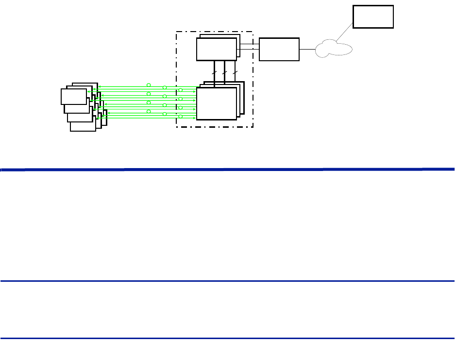
TheFiber‐DASsystemtypicallyconsistsofthreemainsegments:
Gateway — TheGatewayactsasafirewallensuringinternaltrafficonthesystemremainsinternalandatthesame
timeallowingawebinterfaceformonitoringandsupervision.ThegatewayalsohandlesSNMPtraps.
Headend — TheHeadendservesastheinterfacewiththeoperator’sbasestation,housingtheunitsrequiredto
transmitandreceivecommunicationsbetweentheoperator’sbasestationandtheremoteunitsoftheFiber‐DAS
system.
Remote Units — theremoteunitsarelocatednearthedistributedantennasandhousetheequipmentnecessary
totransmitandreceivecommunicationsbetweentheantennaandtheheadend.
Figure 1
Remote
Unit
Remote
Unit
Remote
Unit
Head End
Gateway
Central
Gateway
Ethernet
Switch
Master
Frame
Unit
Master
Frame
Unit
Master
Frame
Unit
(BGW/RGW)
Fiber-DAS System
Gateways
ThegatewaysofferedincludetheCentralGateway(CGW),BaseStationGateway(BGW)andRemoteGateway
(RGW).
ForremotesupervisionofaFiber‐DASagateway(RGWorBGW)isinstalled.BGWsandRGWsaretypicallylocated
withtheheadendequipment,theRGWisasmallercompactembeddedsolutionwhiletheBGWisafullfeatured
Linuxserverthatcanbesetupinmanydifferentways.
CGWsareusedformonitoringmultipleFiber‐DASsystems,communicatingwiththeBGWsandRGWs.
Central Gateway (CGW)
TheCGWisusedtoprovideasingleremoteaccesspointandtocompilealarmsfrommultipleBGW/RGWnetworks.
Theunitisaself‐poweredLinuxbasedserver.
Base Station Gateway (BGW)
TheBGWassignsIPaddressestoallthemodulesintheFiber‐DASsystem,includingtheHeadendandRemoteUnits
aswellastheircomponents.
TheBGWisaself‐poweredLinuxbasedserver.
FeaturesoftheBGW:
Webinterfaceconfiguration
Automaticdetectionofmodules
AutomaticdetectionofRemoteUnits
Capableofhandlinglargesystems
Functionsforstatistics
FiberDistributedAntennaSystem(FiberDAS)
5
NorthboundcommunicationtoCGW
Includesfirewalltoprotectlocalnet
PortaltoyourMasterUnit
User‐providedcertificatebasedsecurityviaHTTPS
Figure 2 Base Station Gateway
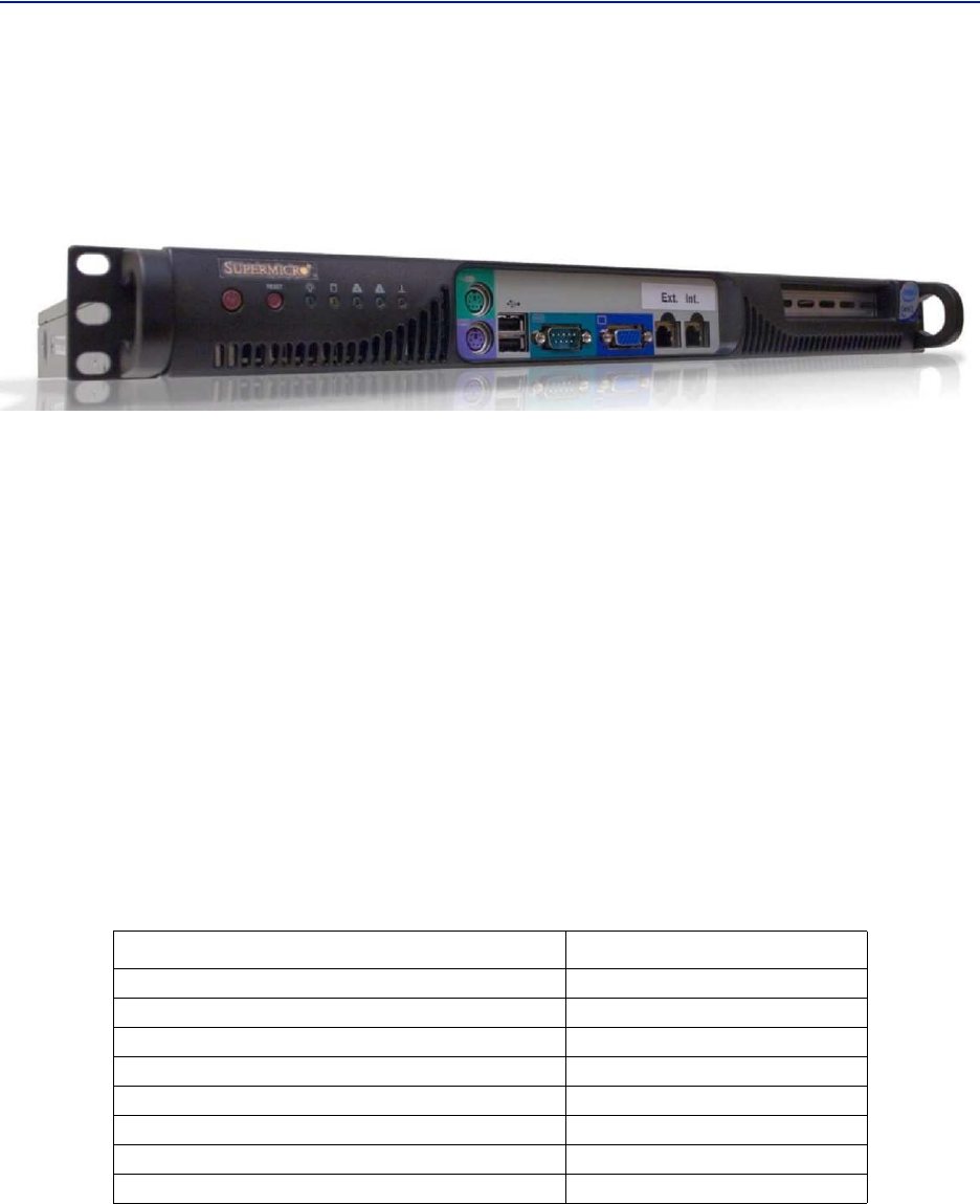
TheBGWhastwoEthernetports‐INTandEXT.
TheINTportisconnectedtotheinternalnetworkintheheadend’sMasterUnittoprovidethelocal
networkforallthemodulesandtheRemoteUnits.Italsoprovides,viathebuilt‐inswitchintheMaster
Unit,awayoflocallyconfiguringthenetwork.Itprovidesthewebinterfaceforallthesettingsofthe
systemaswellasmanyotherfunctions.
TheEXTportisa“northbound”EthernetportthatallowstheBGWtoconnecttotheInternet,oraWAN/
MANtypeoflargernetwork.Thismeansthatthesystemcanbemonitoredandmanagedremotely.
TheBGWistheunitresponsibleforalarmhandlingandremoteforwardofalarmseitherbySMTPmailforwardingor
bySNMPtraps.AMIBfileforyourSNMPsystemisavailablefromBirduponrequestaswellasdocumentation
regardingSNMP.
IftheBGWisreplacedtheRemoteUnitsmaynotshowupimmediately.Thisisduetotheleasetimeontheaddress
theyhave.Eventuallytheywillrequestanewaddressandwhenthisisdonetheywillshowup.
TheBGWcanalsolaunchVPNtunnelstoaremotesupervisioncenter,theCGW.TheCGWmakesitpossibleto
managemultiplesystemsfromasinglelocation.TheCGWcanhandlealargenumberofsuchtunnels,providinga
centralpointforsupervisingalltheinstallationsandcollectingalarmsandstatisticsfromallthesystemsaswellas
centralizedalarmmanagement.TheBGWcansupportasecondVPNtunneltotheBirdmanagementcenter
providingsupervisionandmanagementassistance,ifneeded.
Table 1
Parameter Value
Inputpowervoltage 100‐240VAC
Inputpowerfrequency 50/60Hz
Operatingtemperature 10to30°C(50to100°F)
Powerrating,Typical <100W
Height 1U
Width 19”(48.26cm)
Depth 14.2”(36cm
Weight <11lbs.(5kg)
BGW Specifications
SystemDescription
6
Remote Gateway (RGW)
TheRGWisasmallunitsimilartotheBGWbutintendedforsmallsystemswherethereareonlyafewremotesor
wherethereisnoheadend.TheRGWhasaformfactorthatallowsittobemountedinsidearepeatercasing.
TheRGWcanbeusedtorunupto4RemoteUnitsfromasingleRepeateronasingleFiber.TheRGWhasthe
capabilitytoconnectnorthboundtoaCGW,justliketheBGW,anditcanalsoforwardalarmsthroughaVPNtunnel
toaCGW.
ThememorycapacityandfeaturesarereducedcomparedtotheBGWbutforasmallsystemwithasinglefiberthis
isanoption.
InremotelocationswithoutEthernet,theRGWcanbeequippedwithamodemtoallowremoteaccesstothe
system.Typicallya3GmodemisusedallowingaVPNtunnelfromtheRGWtoaCGW,enablingsupervision,
monitoringandcontrolofthesystem.
Headend
Theheadendconsistsofa19‐inchrackwithmodulesthatareselecteddependingonthesystemdesign.Generallyall
headendUnitscontain:
Networkswitch‐connectscommunicationpathsbetweenthemodules
InterconnectUnit(ICU)‐RFsplitter/combiner(rack‐mountunitormoduleintheMFU)
MasterFrameUnit(MFU),maycontainsomeorallofthefollowing:
Powersupply
BaseStationInterfaceUnit(BIU)
Fiber‐OpticInterfacecard(FOI)
Repeater
ICU
ADHCPserverbuiltintotheRGWandBGWwillassignIPaddressestoalltheheadendsubunitsintherackandthe
RemoteUnitswhentheyareconnectedtothesystem.Theconfigurationisautomaticandcreatesaprotectedsub‐
netforthesystem.
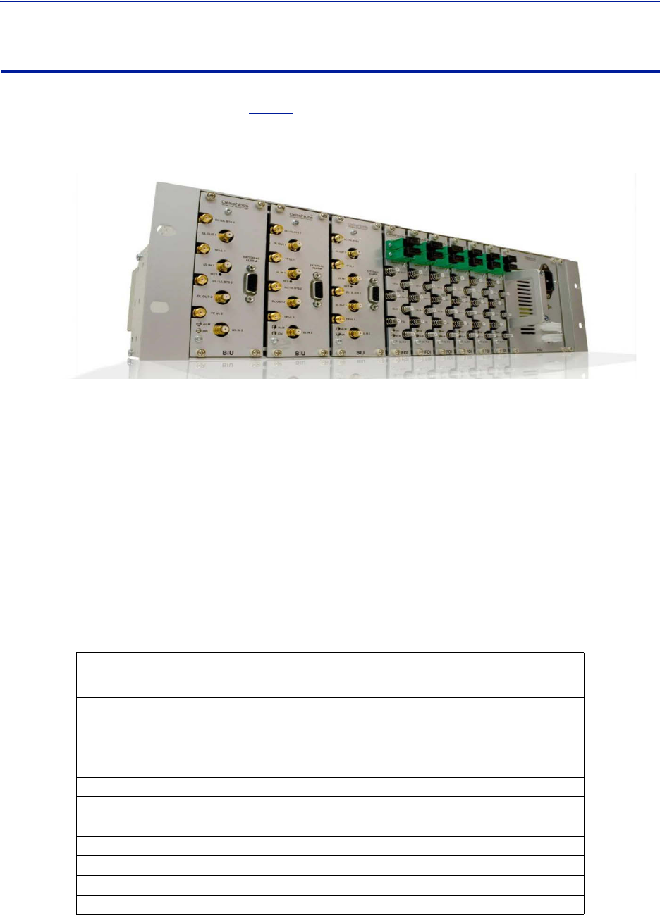
DCS - Network Switch
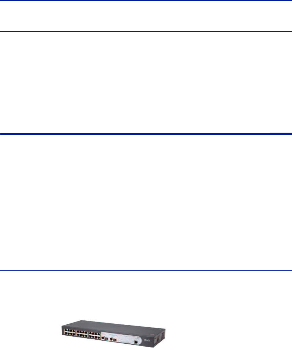
ThenetworkswitchisanACpowered,24‐portswitchwithSpanningTreeProtocol(STP).Thenetworkswitch
providesanEthernetlinkbetweentheMFUandtheBGW.EachcardslotintheMFUhasadedicatedEthernetport,
eachportisconnectedtothenetworkswitchandthenetworkswitchisconnectedtotheBGW.
ADCpoweredoptionisalsoavailable.
Actualnetworkswitchmaybe
differentfromtheimage.
FiberDistributedAntennaSystem(FiberDAS)
7
Master Frame Unit (MFU)
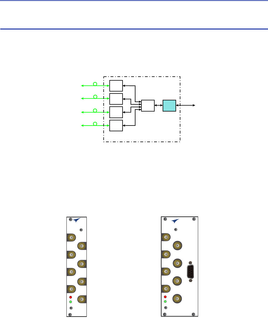
TheMasterFrameUnit(MFU)housesthePowerSupplies,BaseStationInterfaceUnits(BIU),InterconnectionUnits
(ICU),andFiber‐OpticInterface(FOI)cards.
Figure3
showsanMFUequippedwith3BIUs,6FOIsandonePower
Supply.
Figure 3 Master Frame Unit
Functional description
OneMFUsupportsseveralmodules,orcombinationofmoduletypes.Themodulescanbeplacedanywhereinthe
frame.Thereare16singleslotcardpositionsineachMFU,howevermodulewidthsvary(seeeachmodule’s
specifications)sothenumberofmodulethatwillfitinanMFUdependsonthemoduletype.OneMFUcanhouseup
to4powersupplies,8ICUs,8wideBIUs,16slimBIUs,16FOIs,orcombinationofmodules.See
Table2
.
EachMFUrequiresatleastonepowersupply,althoughthepowersupplydoesnotneedtobehousedwithinthe
MFU.QuiteoftenasystemhasmorethanonepowersupplyandtheyareusuallyplacedtogetherinoneMFUfor
easyaccess.EachMFUhastwopowerinputconnectors,oneprimaryandoneredundant.Aredundantpowersupply
connectedtoanMFUensurescontinuedoperationifoneofthepowersuppliesshouldfail.
TheMFUcontainstwoventilationfanscirculatingambientairthroughtheunitshousedintheframe.Thesearehigh
qualityfanswithahighmeantimebetweenfailure(MTBF).
EachModuleintheMFUareassignedanIPaddressesviaDHCPleases,modulesinherittheMACaddressfromthe
backplane,thisensuresthatanewmoduleinsertedintherackreceivesthesameIPaddressastheoneitis
replacing,withouttheneedofmanualconfiguration.
Table 2 MFU Specifications
Parameter Value
Powerconnector Molex,10Pin
Ethernetconnector RJ45
Weight(withoutmodules) 5.5lbs(2.5kg)
Temperaturerange,Operational 0to45°C(32to113°F)
Width 19”(48.3cm)
Height3U,5.25”(13.34cm)
Depth 11.8”(30cm)
Maximumnumberofeachtypeofmodulessupported
PSU 4
BIU(DBI3xx,DBI3xxC(compact)) 8,16
FOI(DOI401,DOI30x) 8,16
ICU 8
SystemDescription
8
Base Station Interface Unit (BIU)
TheBaseStationInterfaceUnit(BIU)istheinterfacebetweentheoperator’sbasestationandtheFiber‐DASsystem.
TheprimarypurposeoftheBIUistoadjustuplinkanddownlinksignallevels.TheBIUispoweredfromtheMFU
backplaneandcommunicatesviaEthernetwiththeBGW.
Figure 4 BIU Signal Flow
Base
Station
Base Station
Interface
Interconnect
Unit
Fiber-Optic
Interface Units
Fiber-Optic
Cables
to
Remote
Units
(Antenna)
Master Frame Unit
FOI
FOI
FOI
FOI
ICU BIU
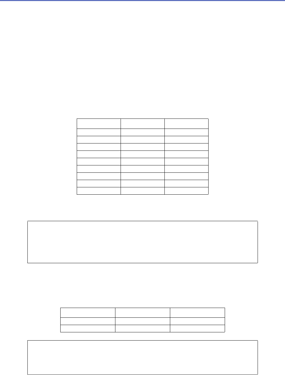
TheBIUhasuplinkanddownlinkRFconnectorsonthefrontpanelandisavailableintwovariants,onecontaining
duplexfiltersoronewithseparateuplink/downlinkpaths,dependingontheneedsfortheconnectiontothebase
station.InmostcasestheduplexedversionwithacombinedDL/ULportsisused.
Inadditiontoduplexingoptions,thereisasingleslotandadualversionoftheBIU:
TheDBI3xx(wideversion)includesanexternalalarmconnector(DB9)andrequirestwoMFUslots.
TheDBI3xxC(compactversion)doesnothaveanexternalalarmconnector(DB9),andusesonlyoneMFU
slot.
Figure 5
BIU
ALM
ON
DL/UL BTS 1
TP UL 1
TP UL 2
DL OUT 1
UL IN 1
DL OUT 2
UL IN 2
DL/UL BTS 2
BIU
ALM
ON
DL/UL BTS 1
TP UL 1
EXTERNAL
ALARM
TP UL 2
DL OUT 1
UL IN 1
DL OUT 2
UL IN 2
DL/UL BTS 2
DBI3xxC DBI3xx
Base Station Interface Unit (BIU)
Functional description
TheBIUhasfourSMAports(femaletype)toconnecttheRBS/BTS.
DuplexedversionshavecombinedDL/ULconnectorsusedtoconnecttotheRBS,andthereareULtest(TP)
connectorsthatcanbeusedtomonitorthesignaloutfromtheBIU.
Non‐duplexed(simplex)versionshavethetestconnectorsreplacedbyULconnectorsandthenormally
combinedUL/DLconnectorsarereplacedbyDLonlyconnectors.
FiberDistributedAntennaSystem(FiberDAS)
9
TheBIUhasfourQMAports(femaletype)thatarenormallyusedtoconnectittoanICU.
Therearetwouplink(input)portsandtwodownlink(output,TX)ports.
Thesearetwoseparatepaths,theisolationbetweenDL1andDL2portsandtheisolationbetweentheUL
1andUL2portsis>50dB.
TherearetwoseparateRFpathsintheBIU.TheBIUisconfiguredforthespecificfrequencybanditwillserve.The
twopathsintheBIUcannothavedifferentfrequencies;aGSM900BIUwillhavetwoGSM900pathsandcannotbe
combinedwithan1800path.SeparatefrequenciesrequiretheuseofanadditionalBIU.
RFpatchcablesareusedtopatchtheDLandULpaths(QMA)totheICU.
TheDBI3xx(dualslot)BIUhasanalarmoutputport(DB9femaleconnector)ontheBIUwhichcanbeusedto
connectexternalalarms.
Table 3 Alarm Port Pinout
TheBIUistechnologyneutralandthedownlinkpathcontainssettableattenuatorsthatcanbeusedtoadjustthe
signalstrengthtoproperlevelsbeforefeedingthemintotheICU.Intheuplinkthereisanamplifierfollowedbya
settableattenuatorusedtoadjustthesignalandthenoiselevelintothebasestationuplink.
AllRFconnectionsaremadeonthefrontoftheBIU.ThemaximumrecommendedinputpowertotheBIUis30dBm.
Ahighpoweralarmisactivatedat>30dBmandalowpoweralarmat<10dBminputpower.
Inputpowerabovetherecommendedlevelcancausepermanentunitfailure.Forhighpowerbasestations,an
attenuatorshouldbeusedtoensurethattheinputpowertotheBIUcanneverexceedspecifications.
Thereisa0dBminputversionoftheBIUavailableonrequest.
Pin Signal (A) Signal (B)
1 RS485+ RS485+
2Alarmout1Alarmout1
3 Ground Ground
4Notconnected Alarmin2
5Notconnected Alarmin4
6 RS485+ RS485+
7Alarmout2Alarmout2
8G Alarmin3
9Notconnected Alarmin1
CAUTION
OverdrivingtheRFsourceinputintotheBIUwillcausepermanentequipmentfailureand
willvoidthewarranty.Theinstallermustensurethatinputlevelsarenotexceeded.
PlanformaximumpoweroutoftheRFsourceandattenuateaccordinglywithexternal
attenuatorsifneeded.
BIU Type Minimum DL Input Maximum DL Input
LowLevel ‐7dBm +7dBm
HighLevel +20dBm +33dBm
CAUTION
TheULfromtheFOIcardiscapableofdamagingtheULportontheBIU.
MaximuminputtotheBIUULshouldbenohigherthan+13dBm.
UsecaretoproperlysetFOIlevelspriortoenablingRF.
SystemDescription
10
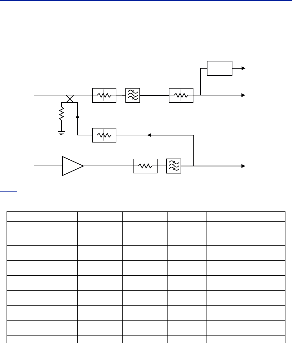
Theschematicin
Figure6
showsoneofthechannelsintheBIU.Thesignaldetectorforthedownlinklevelalarmsis
showninthetoprightcorner.
TheUL1andUL2uplinktestportsare3dBlowerthanthesignalonthecorrespondingDL/ULBTSport.
Figure 6 Schematic of One BIU RF Path
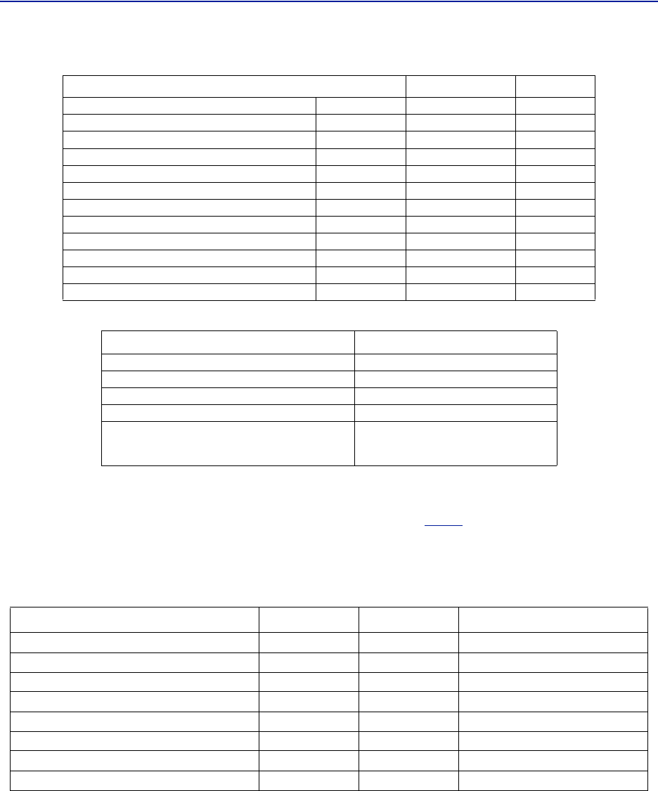
Table4
listsstandardcellularBIU’s.Otherconfigurationsareavailableuponrequestaswellasunitswithoutinternal
duplexfiltering.
Table 4 Standard Variants of the BIU
Configuration UL MHz DL MHz RF Input High Level P/N Low Level P/N
2xVHF 136‐174 136‐174 Duplex DBI312 DBI412
2xTETRA390MHz†
†Severaloptionsexistsfor5MHzstandardbandsforTETRA
380‐385 390‐395 Duplex DBI301 DBI401
2xUHF 450‐470 450‐470 Duplex DBI313 DBI413
2x700MHZABC‐band 698‐716 728‐746 Duplex DBI307 DBI407
2x700UpperC777‐756 746‐756 Duplex DBI304 DBI404
2x700PublicSafety 799‐805 769‐775 Duplex DBI314 DBI414
2xSMR800 806‐824 851‐869 Duplex DBI303 DBI403
2x850MHz 824‐849 869‐894 Duplex DBI308 DBI408
2x800 832‐862 791‐821 Simplex DBI305 DBI405
2xGSM‐R900 876‐880 921‐925 Duplex DBI310 ‐
2x900MHz 880‐915 925‐960 Duplex DBI309 DBI409
2x1800MHz 1710‐1785 1805‐1880 Duplex DBI318 DBI408
2x1900MHz 1850‐1915 1930‐1995 Duplex DBI319 DBI419
2xUMTS2100MHz 1920‐1980 2110‐2170 Duplex DBI320 DBI420
2xAWS2100MHz 1710‐1755 2110‐2155 Duplex DBI321 DBI421
2xLTE2600 2500‐2570 2620‐2690 Duplex DBI326 DBI426
FiberDistributedAntennaSystem(FiberDAS)
11
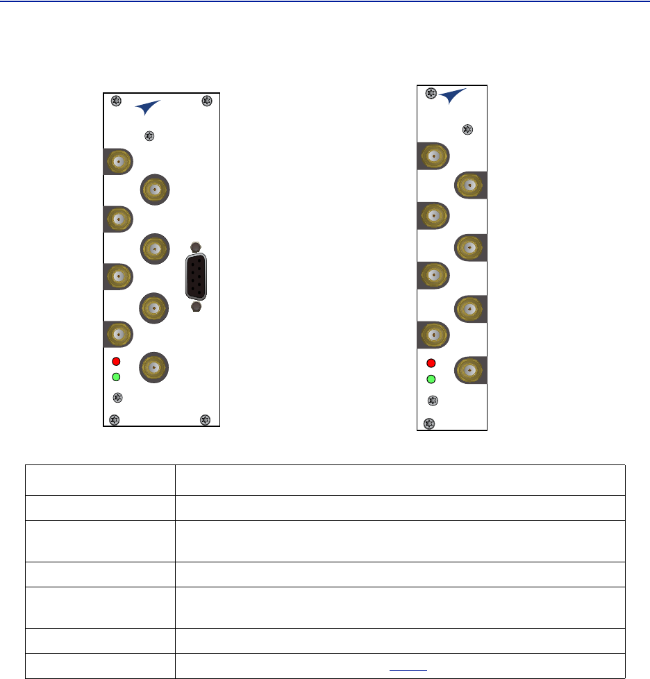
Table 5 RF and Electrical Performance of the BIU
Table 6 BIU Mechanical Specifications
BIU Indicator Operation
TherearetwoLEDslocatedontheBIUfrontpanel.OneisthepowerLED(green),theotheristhealarmLED(red).
BothLEDsindicateanumberofstatesbydifferentflashingsequences,see
Table7
.
InanerrorstatethewebinterfaceshouldbeusedtochecktheactualconditionoftheBIUbuttheLEDscangivea
quickindicationonthestateoftheunit.TheLEDsarealsousefulforlocatingthephysicalunitifseveralBIUsare
installedinthesamerack.
Table 7
State ON LED ALM LED Note
Booting 2Hz Off Normalboot
Bootingstandalonemode 2Hz 2Hz Notattachedtorack
BootingreadofMACaddressfailed 2Hz On Error
Starting 0,1Hz90% 0,1Hz90% Kernelstartup
Operation 0,5Hz10% OffNormaloperation
Operation 0,5Hz10% 1Hz10% Minoralarmstate
Operation 0,5Hz10% 2Hz25% Majoralarmstate
Operation 0,5Hz10% On Criticalalarmstate
Indicator Behavior
Parameter Value Unit
Downlinkattenuation Settable 10‐30±3dB
UplinkGainformodules<1000MHz Settable 10to20±3dB
UplinkGainformodules>1000MHz Settable ‐10to10±3dB
IM3performance >55 dB
Maxinputnon‐destructive >36 dBm
Highinputalarmthresholdlevel 33 dBm
Lowinputalarmthresholdlevel 10 dBm
Inputreturnloss >20 dB
ImpedanceforallRFports 50 Ω
Isolationbetweenports >60 dB
Powerconsumption <15 W
Tempe raturerange 0‐45 °C
Parameter Value
BasestationRFports SMA,Female
Testportsuplink(ifpresent) SMA,Female
InterconnectingRFportstoICU QMA,Female
Alarmconnector(optional) DB9,Female
ModuleWidth
DBI3xx
DBI3xxC(compact)
2Slots
1slot
SystemDescription
12
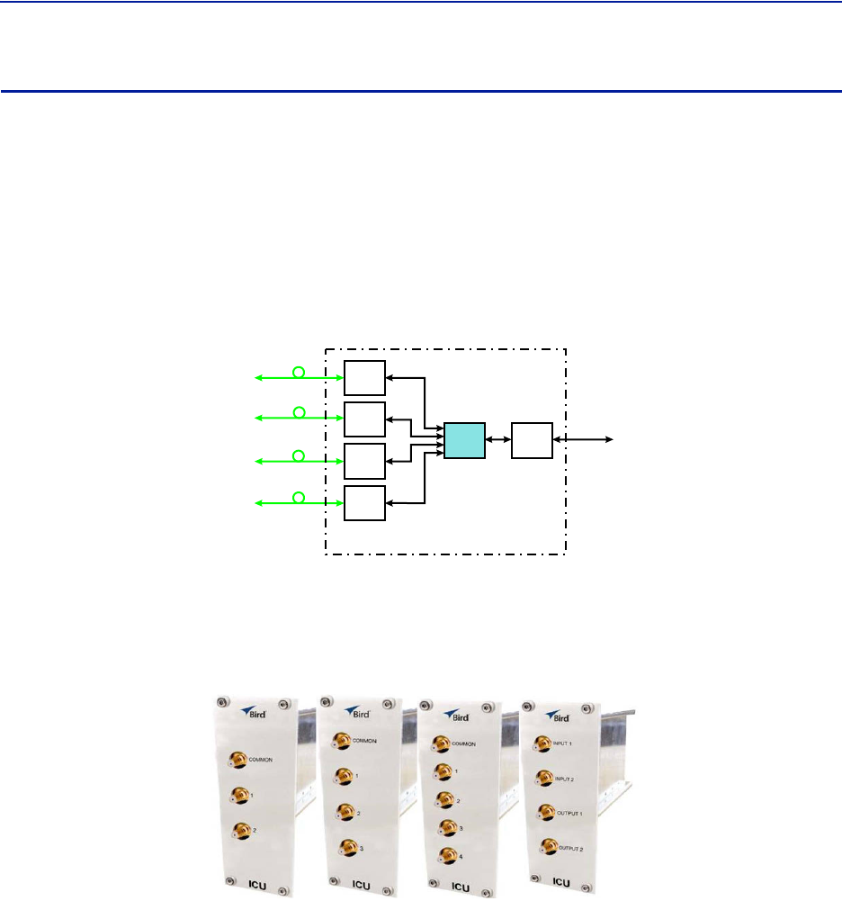
Figure 7 BIU Interfaces
BIU
ALM
ON
DL/UL BTS 1
TP UL 1
EXTERNAL
ALARM
TP UL 2
DL OUT 1
UL IN 1
DL OUT 2
UL IN 2
DL/UL BTS 2
BIU
ALM
ON
DL/UL BTS 1
TP UL 1
TP UL 2
DL OUT 1
UL IN 1
DL OUT 2
UL IN 2
DL/UL BTS 2
Item Description
Connectionfromtheradiobasestation(RBS).
TestportfortheuplinkoftheDL/ULBTSport‐6dB.Thesignalwillbe3dBm
belowtheDL/ULBTSport.PortisnotvalidonthesimplexBIU.
SimplexdownlinkfeedtotheFOI.
SimplexuplinkfromtheFOI.TheBIUwillattenuateand/oramplifythesignal
andthenroutetotheDL/ULBTSport.
Usedforexternalalarmmonitoring(DBI3xx,twoslotversiononly).
TheLEDsindicatevariousstates,see
Table7
.
DL/ULBTS1/2
TPUL1/2
DLOUT1/
2
ULIN1/2
EXTERNALALARMS
ON/ALMLED
FiberDistributedAntennaSystem(FiberDAS)
13
Interconnect Unit (ICU)
Interconnectunits(ICU)areusedtocouplesignalsbetweentheBIUsandtheFOIs.
ThefunctionalpurposeoftheICUis:
Downlink‐SplitthesignalfromtheBIUandroutethebalancedsignals(minusinsertionloss)totheFOIs.
Uplink‐CombinethesignalsfromtheFOIsandroutethesumofthesignals(minusinsertionloss)tothe
BIU.
TheRFportsontheICUareQMA.
Figure 8 Interconnect Unit Signal Flow
Base
Station
Base Station
Interface
Interconnect
Unit
Fiber-Optic
Interface Units
Fiber-Optic
Cables
to
Remote
Units
(Antenna)
Master Frame Unit
FOI
FOI
FOI
FOI
ICU BIU
MFU ICU
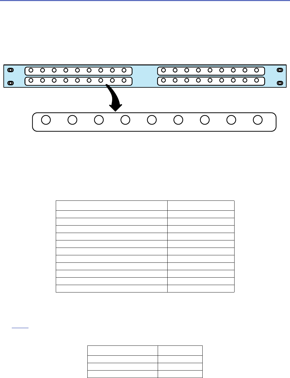
TheMFUICUsareavailableinseveraldifferentconfigurationstosupportavarietyofsystemconfigurations.
TheseunitsareinsertedintotheMFUandprovidesignalroutingtoandfromtheBIUsandFOIs.
Figure 9 MFU ICU
SystemDescription
14
Rack-mount ICU (DIU301, DIU302)
TheRack‐mountICUisa1Uunitthatcontainsfourfieldscontainingsplitters/combiners.Eachfieldiscapableof
splittingoneinputintoeightoutputsorcombiningeightinputsintooneoutput.
Figure 10 Rack-mount ICU
Eachofthe4fieldshasaCOMMONportandports1‐8.
Whenusedasacombiner,thesignalstocombineareconnectedtoinputports1‐8,thesumofthesignals
(minusinsertionloss)willbeoutputontheCOMMONport.
Whenusedasasplitter,thecombinedsignalisinputontheCOMMONportandoutputonports1‐8,with
theoutputportshavingbalancedsignals(minusinsertionloss).
Table 8 Rack-mount ICU Specifications
QMA cable kit
AQMAcablekit(BirdpartnumberDCC320)isavailableforusewiththeICU.Thekitcontains32QMAtoQMAcables
(see
Table9
)thatcanbeusedtopatchbetweentheBIUtotheICU,BIUtotheFOIorICUtoFOI.
Table 9 QMA Cable Kit
Parameter Value
Insertionloss(nominal)‐DIU301 37dB
Insertionloss(nominal)‐DIU302 21dB
Bandwidth‐DIU301 88‐2700MHz
Bandwidth‐DIU302 88‐2700MHz
OperatingTe mperatu re ‐25to+55C(‐13to+131F)
Impedance 50Ohm
IM3performance >50dB
Returnlossperformance >20dB
Maximumcommonportpower 20dBm
Isolationbetweenportsinsamestrip >15dB
Isolationbetweenportsindifferentstrips >50dB
Length Quantity
250mm(9.8”) 13
350mm(13.8”) 13
500mm(19.7”) 6
FiberDistributedAntennaSystem(FiberDAS)
15
Fiber Optic Interface (FOI) unit
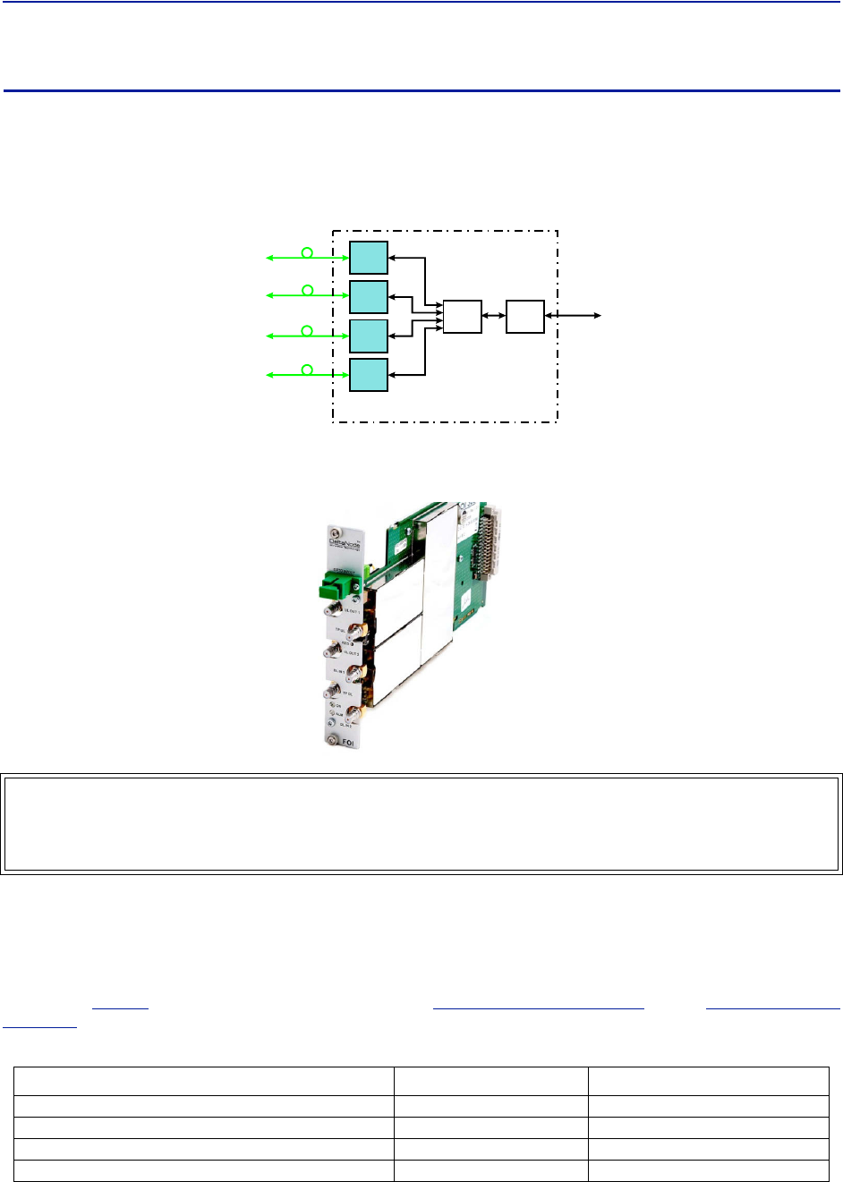
TheFOIconvertstheRFsignalsinthedownlinktofiber‐opticallaseroutputthatistransmittedonthefibertothe
remoteunit.ItalsoreceivesthelaserlighttransmittedbytheRemoteUnitandconvertsitbacktoRFsignalsthatare
thenroutedtotheICUand/orBIU.
Figure 11
Base
Station
Base Station
Interface
Interconnect
Unit
Fiber-Optic
Interface Units
Fiber-Optic
Cables
to
Remote
Units
(Antenna)
Master Frame Unit
FOI
FOI
FOI
FOI
ICU BIU
FOI Signal Flow
TheFOIispoweredfromtheMFUbackplaneandcommunicatesviaEthernetwiththeBGW.
Figure 12 Fiber Optic Interface (FOI) Unit
ThisinterfaceisdesignedtoworkwithSC‐APCconnectors(8°angledphysicalconnector)andsinglemodefibers
only.AllconnectorsbetweenthemasterunitandtheremoteunitmustbeAPC,otherwiseproblemswithreflections
willarise,whichcouldcausesevereproblemsinthesystem.
TheEthernetcommunicationbetweentheHeadendandtheRemoteUnitstakesplaceontwosub‐carriersintheFOI
wheretheEthernetsignalsaresuperimposedontheRFsignals.
Asshownin
Table10
,BirdofferstwostylesofFOIcards.The
"DOI300SeriesFOI"onpage16
andthe
"DOI401SeriesFOI"
onpage19
.
Table 10 FOI Variants
WARNING
Avoidlookingintoconnectedfibersandreceptacles.
ThelaserusedinthissystemisaClass3blaserthatproducesinvisibleinfra‐redcoherentlight.Notsafetoview
withopticalinstruments.Alwaysputtheprotectioncapsonunusedfibersandreceptacles.
Parameter Fiber Ports Wavelength
DOI301 2 1310nm
DOI302(WDM) 1 1310nm
DOI308x 1 variouswavelengthsavailable
DOI401 4 1550nm
SystemDescription
16
DOI300 Series FOI
TheDOI300seriessupportsasinglefiberopticlink.Thefiber‐opticinterfacecaneitherbeaWDM(DOI302)whichis
mostcommonlyusedoranoptionalduplexfeedwithseparateULandDLfibers(DOI301).BirdalsooffersaWDM
option(DOI380x).TheWDMutilizestheduplexfeedstylecardbutthewavelengthforthedownlinkaredefinedby
the"x"intheDOI380xpartnumber.NotethattheRemoteUnitwillneedtobeorderedwiththecorrectWDM
uplinkwavelength.RefertothechartfortheWDMwavelengthsoffered.
DOI300 Series Serving Multiple Remotes
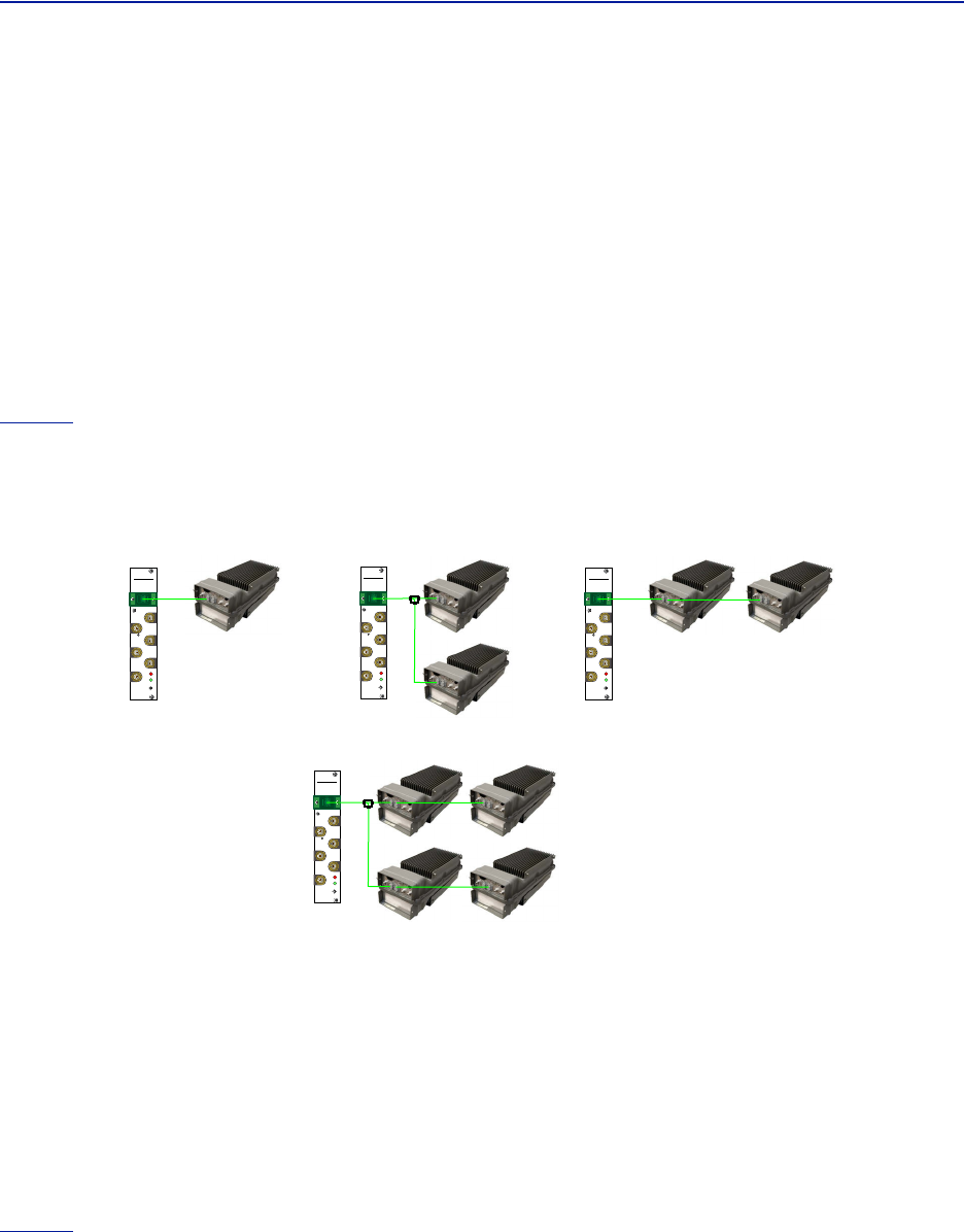
TheDOI300SeriesFOIcanserveupto4RemoteUnitsonasinglefiberrunwhenusinganopticalsplitterinthefirst
RemoteUnit.WhenutilizingtheDOI302WDMmoduleeachRemoteUnitintheseriesmusthavedifferentoptical
wavelengthsintheuplinkpathtoavoidinterference.
Whenutilizingopticalsplitters,theopticallossofthesplittermustbeaccountedforintheopticallinkbudget.The
DOI300seriesFOIhasamaximumlinkbudgetof15dBo.
Figure13
showstheallowedFOItoFOR/Remoteconfigurations.BirdoffersvarioussplitteroptionsfortheFOR/
Remotetohelpaccountforopticallosses.Thestandardopticalsplitterwillhavebalancedoutputsforeachpath.
ConsultwithBirdengineeringforspecialapplications.
Figure 13 FOI to Remote Unit Configurations
DeltaNode
Wireless Technology
TM
FOI
ALM
ON
UL OUT 1
OPTO IN/OUT
TP DL
RES
TP UL
DL IN 1
DL IN 2
UL OUT 2
DeltaNode
Wireless Technology
TM
FOI
ALM
ON
UL OUT 1
OPTO IN/OUT
TP DL
RES
TP UL
DL IN 1
DL IN 2
UL OUT 2
Point-to-Point Daisy-Chained Remotes
Hybrid Split
DeltaNode
Wireless Technology
TM
FOI
ALM
ON
UL OUT 1
OPTO IN/OUT
TP DL
RES
TP UL
DL IN 1
DL IN 2
UL OUT 2
Point-to-Multipoint
DeltaNode
Wireless Technology
TM
FOI
ALM
ON
UL OUT 1
OPTO IN/OUT
TP DL
RES
TP UL
DL IN 1
DL IN 2
UL OUT 2
Functional description
TheFOIhasanominalgainof35dBandthelasertransmittershouldseeamaximumcompositeinputpowerof
0dBm.Thismeansthatfor0dBattenuationinthedownlinkamaximuminputof‐35dBmcompositepoweris
recommended(whenattenuatorsaresetto0dBm).Ifthedownlinkattenuatorissettoahighervaluethemaximum
recommendedinputisadjustedaccordingly.
Theoutputpowerofthelaseriscalibratedto3000µW.Thiscanbeusedtocheckthelossoverfiberintheremote
becausetheremotereportsthereceivedopticallevels.Thelossmaybedifferentintheuplinkcomparedtothe
downlinkbecauseofdifferentwavelengthsonthelaser.
TheFOIcontainsseveraladjustableattenuatorswhichareusedtocompensateforlossbeforetheFOI(e.g.inthe
ICU)andforlossonthefiberintheuplink.TherearetwosetsofRFportsontheFOIthatcanbeusedtoconnect
signalsfromtwodifferentstripsintherack‐mountICU,ortwodifferentMFUICUs.
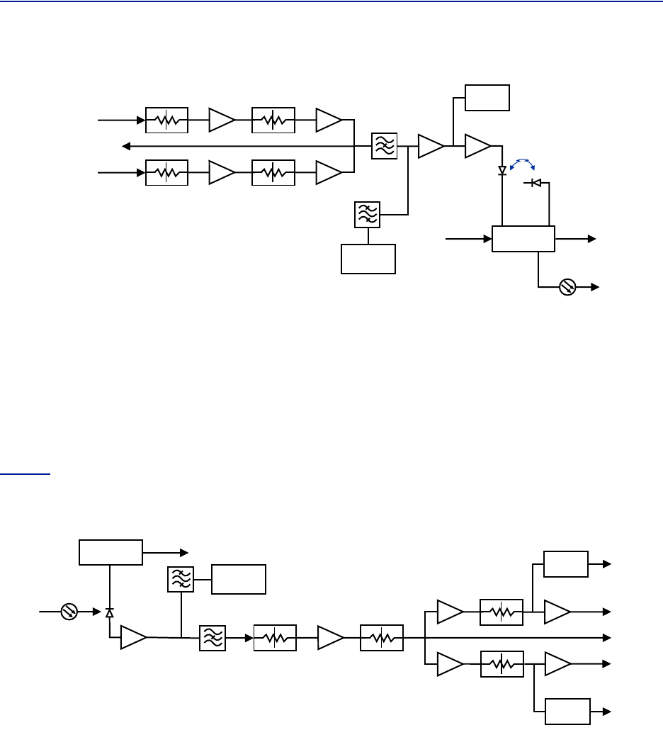
Figure14
isablockdiagramshowingthedownlinkpathintheFOIandhowthetestportisconnected.Therearetwo
attenuatorsthatcanbesetinthedownlinkpath.Thisallowsforbalancingtheinputsignalsfromtwodifferentsignal
sourcessothattheycansharethedynamicsofthelaserproperly.
FiberDistributedAntennaSystem(FiberDAS)
17
Figure 14
DETECTOR
LASER
DRIVER
ETHERNET
MODEM
OPTO OUT
DETECTOR
MONITOR
TX-LVL
DL IN 1
DL IN 2
TP DL
STEP ATT
Attenuator 1
Downlink 1
Attenuator 1
Downlink 2
Attenuator 2
Downlink 1
Attenuator 2
Downlink 2
STEP ATT
STEP ATT
STEP ATT
FOI Downlink Block Diagram
TheRFdrivelevelsaremeasuredandaccessibleinthewebinterface.
TPDLisatestpointmeasurementportforthedownlinkpath.TheRFlevelatTPDLwillbethesameastheinputto
theDLportsminustheGUIattenuatorsettings.
TPDL=“DLIN1"minus“Att.1Downlink1"minus“Att.2Downlink1".
TPDL=“DLIN2"minus“Att.1Downlink2"minus“Att.2Downlink2".
Example:InputintoDLis‐25dBmwiththeGUIsettingfor“Att.1Downlink1"of10andaGUIsettingfor“Att2
Downlink1"of0.Thetestpointmeasurementwillbe:‐25dB(input)minus10dB(attenuator#1)minus0dB
(attenuator#2)=‐35dBm.
Figure15
isablockdiagramshowingtheuplinkpathintheFOIandhowthetestportisconnected.Therearetwo
commonattenuators,andtwouplinkattenuatorsthatcanbesetintheuplinkpath.
Figure 15 FOI Uplink Block Diagram
DETECTOR
DETECTOR
CURRENT
SENSOR
ETHERNET
MODEM
OPTO IN
RX-LVL
UL OUT 2
UL OUT 1
TP UL
Attenuator
Common 1
PHOTO
DETECTOR
Attenuator
Common 2
Attenuator
Uplink 1
Attenuator
Uplink 2
STEP ATT STEP ATT
STEP ATT
STEP ATT
RX POWER 1
RX POWER 2
TheULtestportontheFOIistappedbeforetheindividualuplinkpathattenuators.TheoutputlevelofTPULwillbe:
TP/UL[dB]=“Att.Uplink1"setting‐20dB
TP/UL[dB]=“Att.Uplink2"setting‐20dB
Example:IftheFOIGUIsettingfor“Att.Uplink1"is0,thetestportuplinkpath1signalswillbe20dBlowerthanthe
uplinksignalonthe“ULOut1"port.
Example:IftheFOIGUIsettingfor“Att.Uplink2"is20,thetestportuplinkpath2signalswillbeequaltotheuplink
signalson“ULOut2"port.
SystemDescription
18
Figure 16 DOI301/302
FOI
ALM
ON
UL OUT 1
OPTO IN/OUT
TP DL
RES
TP UL
DL IN 1
DL IN 2
UL OUT 2
DOI302
With WDM
DOI301
Without WDM
FOI
ALM
ON
UL OUT 1
OPTO OUT
OPTO IN
TP DL
RES
TP UL
DL IN 1
DL IN 2
UL OUT 2
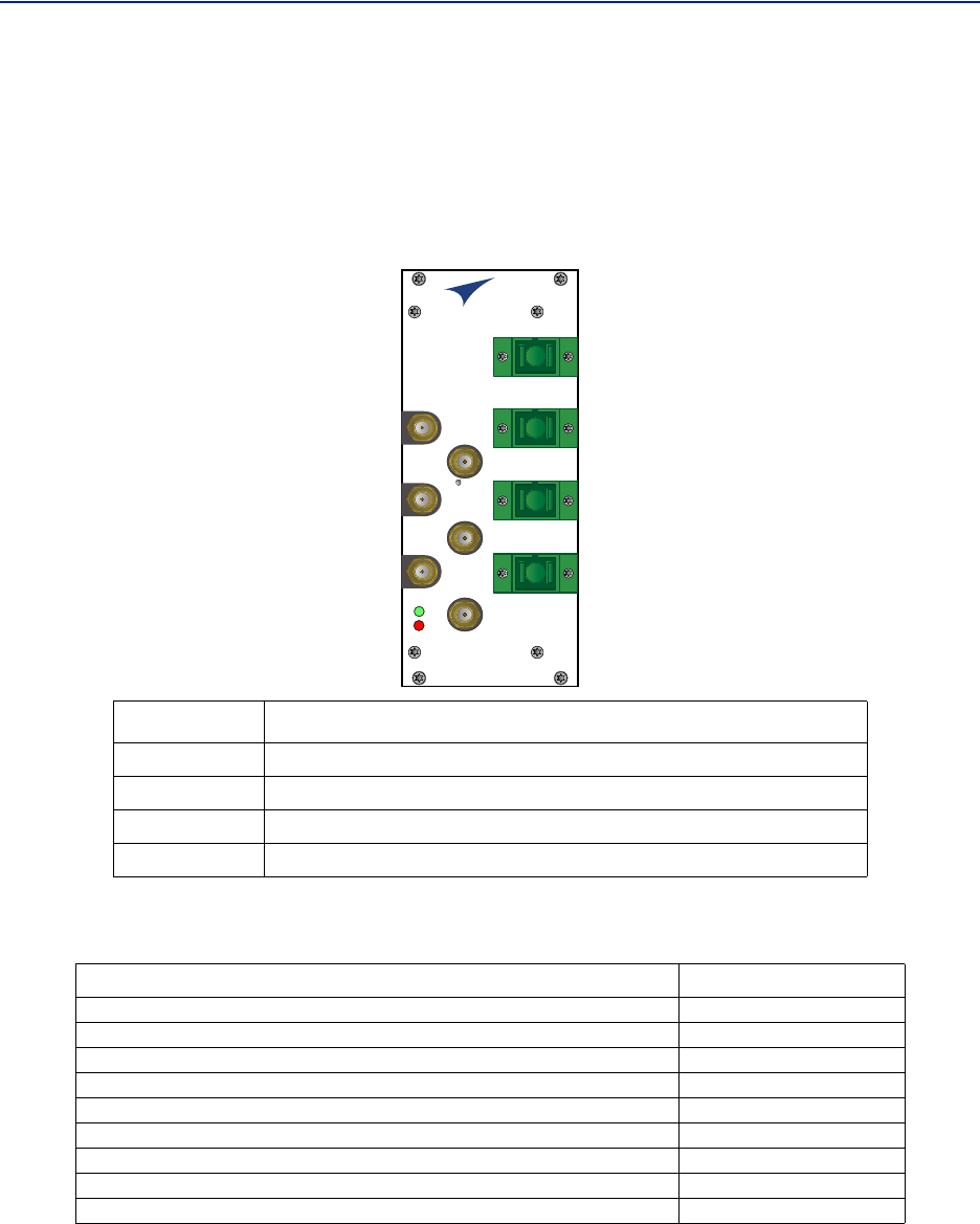
Interfaces
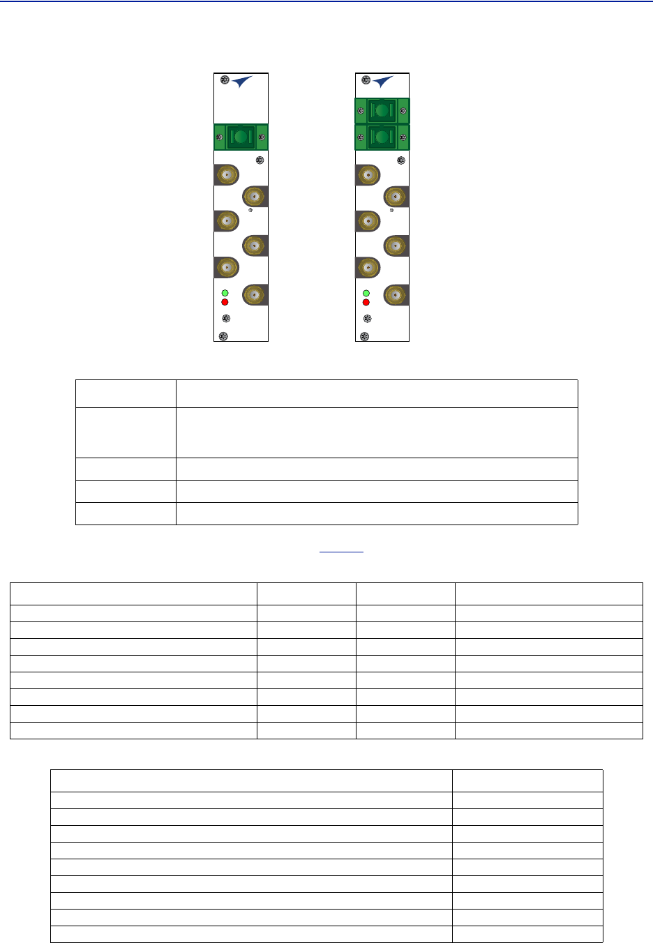
ThetwoLEDsontheunitprovideFOIstatusasshownin
Table11
.
Table 11 FOI LED Indicators
Table 12 DOI302 Specifications
Item Description
OPTOIN/OUT
SC‐APCconnectionfortheopticalfiber.
DOI302modulewithbuiltinWDMhasasingleconnector(combinedRX/TX).
DOI301modulewithoutWDMhastwoconnectors,oneforTXandoneforRX.
ULOUT1/2 Uplinkports(QMA)totheICU.
DLIN1/2 Downlinkports(QMA)totheICU.
TPUL/DL Testports(QMA)usedtocheckthesignallevelsornoiseinthesystem.
State ON LED ALARM LED Note
Booting 2Hz Off Normalboot
Bootingstandalonemode 2Hz 2Hz Notattachedtorack
BootingreadofMACaddressfailed 2Hz On Error
Starting 0,1Hz90% 0,1Hz90% Kernelstartup
Operation 0,5Hz10% Off Normaloperation
Operation 0,5Hz10% 1Hz10% Minoralarmstate
Operation 0,5Hz10% 2Hz25% Majoralarmstate
Operation 0,5Hz10% On Criticalalarmstate
Parameter Value
MaximumfiberlossfromMUtoRU,Optical, 15dBo
Opticaloutputpower,Calibrated 3000µW
MaximumnumberofRUsupportedonsinglefiber 4
InputRFpowerrecommended,Composite ‐50to‐35dBm
Powerconsumption <15W
OperationalTe mperaturerange 0to45°C(32to133°F)
ModuleWidth 1cardslot
Opticalconnectortype SC‐APC
RFconnectortype QMAFemale
FiberDistributedAntennaSystem(FiberDAS)
19
DOI401Series FOI
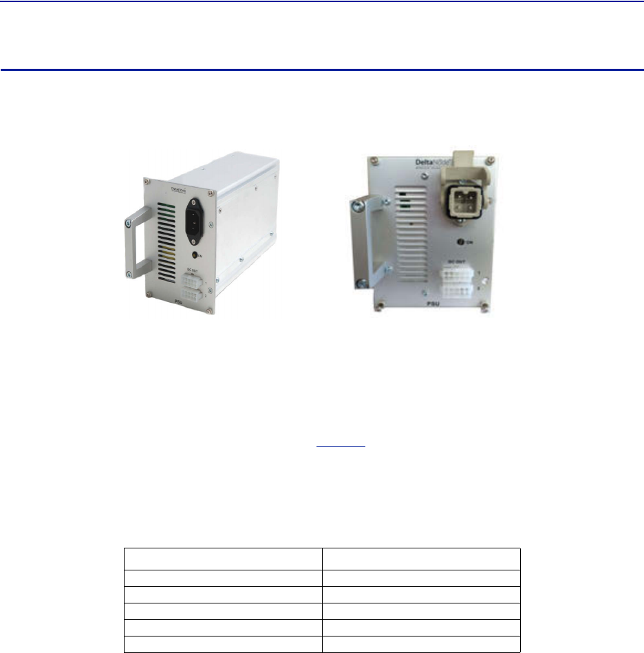
TheDOI401fourportFOIisverysimilartoDOI302expectthatithasfourWDMopticalportsinsteadofone.This
allowstheusertoinstalldedicatedfiberstoeachRemoteUnitwithouthavingtobalanceopticalsplitterlinkbudgets
foreachremoteinagroup.Thebalancedsplitterlossisaccountedforinthe7dBolinkbudgetoftheDOI401.Unlike
theDOI302,theDOI401doesnotrequiretheULopticalsignalstobeondifferentwavelengths.
Figure 17 DOI401 Interfaces
OPTO IN/OUT 1
OPTO IN/OUT 2
OPTO IN/OUT 3
OPTO IN/OUT 4
FOI
ALM
ON
UL OUT 1
TP DL
RES
TP UL
DL IN 1
DL IN 2
UL OUT 2
Table 13 DOI401 Specifications
Item Description
OPTOIN/OUT SC‐APCconnectionsfortheopticalfiber.
ULOUT1/2 UplinkportstotheICU/BIU.
DLIN1/2 DownlinkportstotheICU/BIU.
TPUL/DL Testportsusedtocheckthesignallevelsornoiseinthesystem.
Parameter Value
MaximumfiberlossfromMUtoRU,Optical, 7dBo
Opticaloutputpower,Calibrated 3000µW
MaximumnumberofRUsupportedonsinglefiber 1
InputRFpowerrecommended,Composite ‐50to‐35dBm
Powerconsumption <20W
OperationalTe mperaturerange 0to45°C(32to133°F)
ModuleWidth 2cardslot
Opticalconnectortype SC‐APC
RFconnectortype QMAFemale
SystemDescription
20
PSU – the rack power supply
ThePowerSupplyUnitprovidesDCpowertotheMasterUnitbackplane.Theunitisshippedas240VACor115VAC
unitsdependingonthecountry.A‐48VDCinputisofferedasanoption.
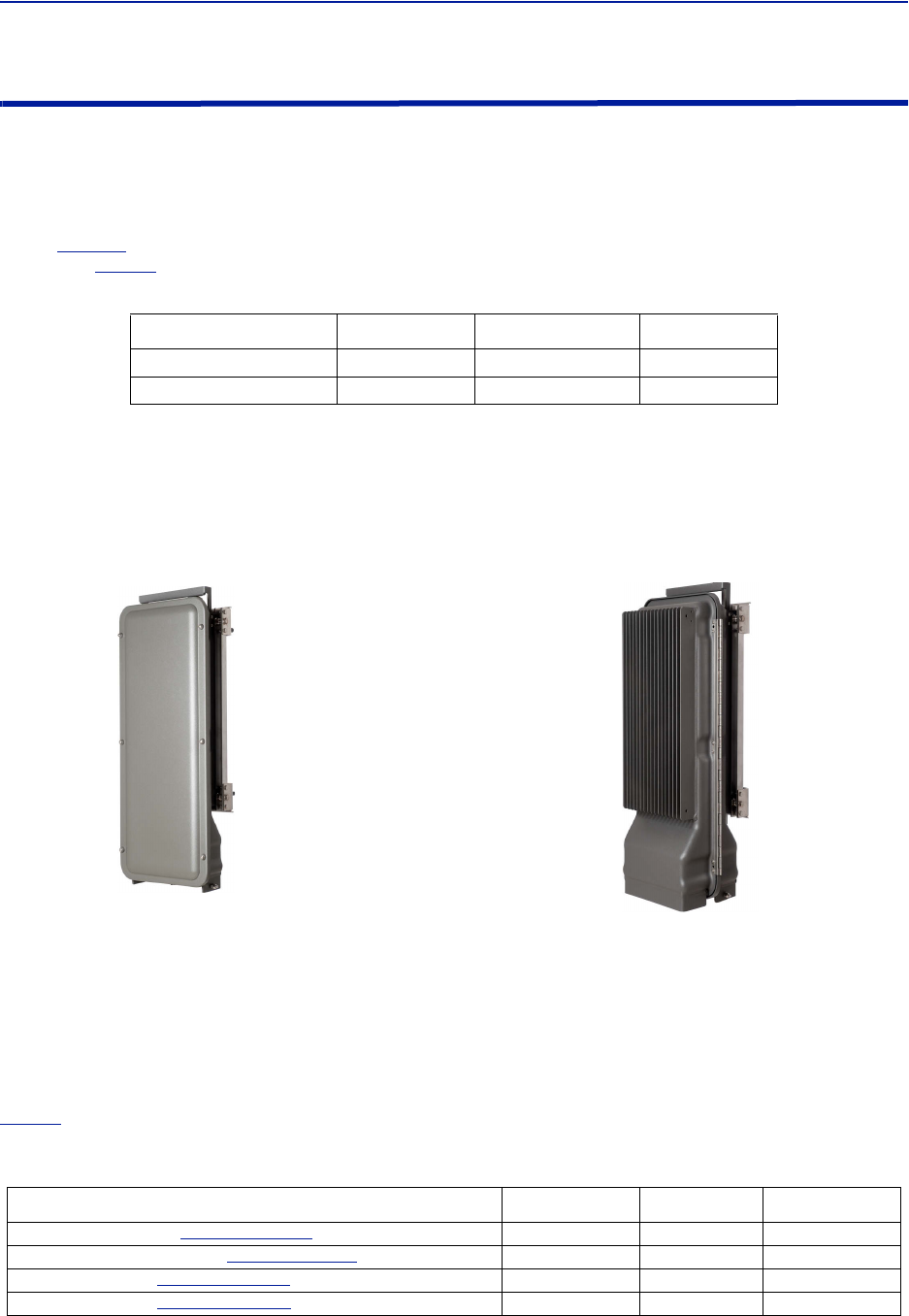
Figure 18 PSU
ACPowerSupply DCPowerSupply
Functional description
TheACpowersupplycanhandleupto16cardsoronechassisfullofcards.TheDCpowersupplyiscapableof
handling11cardsoronefullchassisthatincludestheDCpowersupply.
Allconnectorsareonthefrontsideofthepowersupply.
Figure18
showsthePSUequippedwithEuropeanpower
inlet.
ThePSUoutputsaretwo10‐pinMolexconnectors,theseareconnectedtothechassistosupplypower.One
connectorshouldalwaysbeconnectedtothechassisholdingthePSU(fordrivingthefans).
Onechassiscanholdupto4powersupplies.TwoPSU’smaybeconnectedtoachassistoprovideredundancy.
Table 14 PSU Specifications
Parameter Value
Inputpowervoltage,Mains 86‐264VAC
Inputpowerfrequency,Mains 50/60Hz
Operatingtemperature 0to45°C(32to113°F)
Powerrating 240W
Width 4cardslots
FiberDistributedAntennaSystem(FiberDAS)
21
Remote Unit (RU)
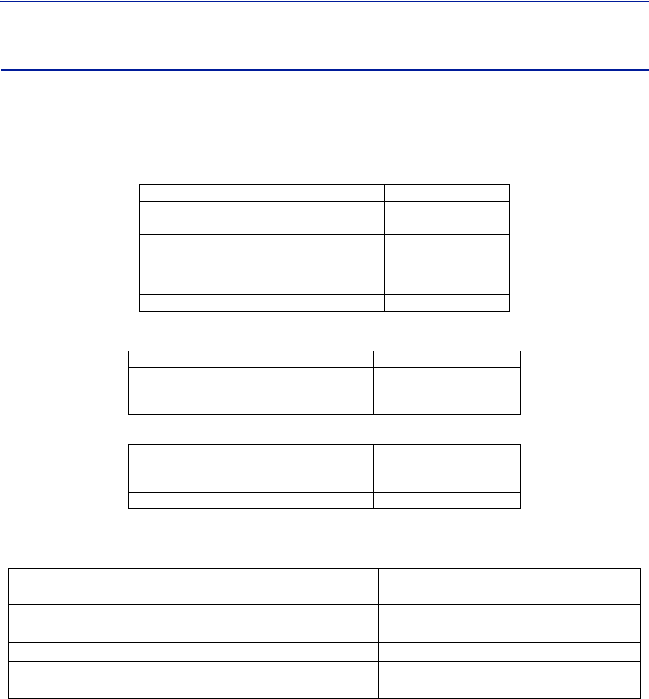
Remoteunitsareavailableinawiderangeoffrequencies,gainandoutputpowertocatertosupportavarietyof
requirements.Remoteunitsarealsocapableofsupportingmorethanonefrequencybandinasingleunit.
Chassis types
Remoteunits(RUs)areavailableintwochassis,asinglecompactchassisfor1‐2bandsandadualchassisforupto4
bands(
Figure19
).Therearemultipleconfigurationsthatallowforvariouspowerlevelofamplifierstobeplacedinto
thechassis.
Table15
showshowthechassismaybeconfigured:
Table 15
Chassis type Low Medium High
Singlechassis 1‐2 1‐2 1
Dualchassis 3‐4 3‐4 2
Chassis Types
Itispossibletohavecombinationsoftheabove.Forexampleitispossibletobuildadualchassiswith2medium
powerbandsand1highpowerbandinthesameremote.Eachsideofadualchassisisvirtuallyidenticaltoasingle
chassisremoteunit.Thisensuresunparalleledflexibilitywhenbuildingmultipleoperator/multiplebandsolutions.
Adualchassismayhave1‐2fiberopticalremoteunits(FOR).Thisallowsforredundantfiberfeeds,multiple‐input
andmultiple‐output(MIMO)applications,anddedicatedamplifiers.
Figure 19
Single Chassis
Remote Unit
Dual Chassis
Remote Unit
Remote Unit Chassis Types
AllRemoteUnitshaveanexcellentnoisefigure,contributingtoanoverallnoisefigureforthewholesystemfrom
remotetohead‐endintothebasestationof<3dBfortheRFlink.
BothchassiscomplywithIP65protectionforuseinanyenvironment.Thedurablecoatingassistsinconvection
cooling.NofansareusedfortheRemoteUnits.
Note: TheheatgeneratedbytheRemoteUnitswhenpoweredupisusedtopreventwateringressinto
units.Remoteunitsmustremainpoweredonwhenmountedoutdoors.
Bothwallorpolemountingkitsareavailableforchassismounting.
Table16
containsalistofthemostcommonremoteunitsthatareusedwiththeBirdFiber‐DASsystem.Variantsare
availableuponrequest.
Table 16 Remote Comparison Table
Product code Pout (ETSI)†
†Actualpowerdeterminedbyfrequencybandandspectrumdemands.
Pout (FCC) Bands
DDR(mediumpower).See
"DDR"onpage22
.26‐30 361‐4
DDS(Highpowerquadband).See
"DDS"onpage26
.41 1‐4
DDH(highpower).See
"DDH"onpage28
.32‐43 43 1‐2
DDU(highpower).See
"DDU"onpage31
.46 1‐2

SystemDescription
22
DDR
ETSI standard
Bird’sDistributedRadioheadisahighperformingwidebandradioheadequippedwithalinearpoweramplifier
supportingallmodulations.Thelightweight,convectioncooledIP65chassissecurestheperformanceinalmostany
environment.
Table 17 General Specifications
Table 18 Specifications DDR100 (Single Band) & DDR200 (Dual band)
Table 19 Specifications DDR300(Triple Band) & DDR400(Quad Band)
Cellular Products
Table 20 Available Products, ETSL
NoiseFigure,Typical 3dB
Delayexcludingopticalfiber <0.5µs
PowerSupply
Standard
Optional
85to264VAC
‐32to‐100VDC
OperatingTe mperatu re ‐25to55°C(32to113°F)
Casing IP65
PowerConsumption,max,DDR100(200) 90(180)W
Dimensions,WxDxH11.8x5.1x27.6in.
30x13x70cm
Weight <26.4lbs(12kg)
PowerConsumption,max,DDR300(400) 270(360)W
Dimensions,WxDxH11.8x8.7x27.6in.
30x22x70cm
Weight <52.9lbs(24kg)
System UL Frequency
MHz
DL Frequency
MHz
Pout (DL)
dBm/c,
1 Carrier
Pout (DL)
dBm/c,
2 Carriers
Standard
TETRA,PublicSafety 380‐385 390‐395 26 23 ETSI
TETRA,Commercial 410‐415 420‐425 26 23 ETSI
TETRA,Commercial 415‐420 425‐430 26 23 ETSI
CDMA450 452.5‐457.5 462.5‐467.53328FCC
GSM‐R876‐880 921‐925 26 23 ETSI
EGSM900 880‐915 925‐960 26 23 ETSI
GSM1800 1710‐1785 1805‐1880 28 25 ETSI
UMTS 1920‐1980 2110‐2170 30 25 3GPP

FiberDistributedAntennaSystem(FiberDAS)
23
FCC/IC standard
Bird’sDistributedRadioheadisahighperformingwidebandradioheadequippedwithalinearpoweramplifier
supportingallmodulations.Thelightweight,convectioncooledIP65chassissecurestheperformanceinalmostany
environment.
Table 21 General Specifications
Table 22 Specifications DDR100 (Single Band) & DDR200 (Dual band)
Table 23 Specifications DDR300 (Triple Band) & DDR400 (Quad Band)
Cellular Products
Table 24 Available Products, FCC/IC
Class B Industrial Booster — ThisequipmentisaClassBIndustrialBoosterandisrestrictedtoinstallationas
anIn‐buildingDistributedAntennaSystem(DAS).
FCC RF Exposure — ThisequipmentcomplieswiththeFCCRFradiationexposurelimitssetforthforan
uncontrolledenvironment.Thisequipmentshouldbeinstalledandoperatedwiththefollowingminimumdistances
betweentheradiatorandyourbody:
Ifsystemwilloperateonmultiplebands,theseparationdistancerequiredshallbeequalto,orgreaterthan,the
bandwiththelargestseparationdistance.
NoiseFigure,Typical 3dB
Delayexcludingopticalfiber <0.5µs
PowerSupply
Standard
Optional
85–264VAC
‐32to‐100VDC
OperatingTe mperatu re ‐25to55°C(32to113°F)
Casing IP65
PowerConsumption,max,DDR100(200) 90(180)W
Dimensions,WxDxH11.8x5.1x27.6in.
30x13x70cm
Weight <26.4lbs(12kg)
PowerConsumption,max,DDR300(400) 270(360)W
Dimensions,WxDxH11.8x8.7x27.6in.
30x22x70cm
Weight <52.9lbs(24kg)
System UL Frequency MHz DL Frequency MHz Pout, DL,
dBm (Composite) Standard
LTELB 698‐716 728‐746 33 FCC/IC
LTEUB 746‐776† 776–806†
†Sub‐bandsavailable
33 FCC/IC
iDEN 806‐824 851‐869 33 FCC/IC
Cellular 824‐849 869‐894 33 FCC/IC
PCS1900 1850‐1915 1930‐1995 33 FCC/IC
AWS 1710‐1780 2110‐2180 33 FCC/IC
WCS2300 2305‐2315 2350‐2360 33 FCC/IC
IMT‐E2500‐2570 2620‐2690 33 FCC/IC
LTE700MHz(DDR700) 204.7cm
iDEN800MHz(DDR850) 173.0cm
PCS1900MHz(DDR1900) 142.9cm
AWS‐12100MHz(DDR2100) 134.9cm
AWS‐32155MHz(DDRAWS3) 97.7cm
WCS2300MHz 97.7cm

SystemDescription
24
IC RF Exposure — EquipmentoperatingintheCellularbandshouldbeinstalledandoperatedwiththefollowing
minimumdistanceofbetweentheradiatorandyourbody:
Ifsystemwilloperateonmultiplebands,theseparationdistancerequiredshallbeequalto,orgreaterthan,the
bandwiththelargestseparationdistance.
TheManufacturer'sratedoutputpowerofthisequipmentisforsinglecarrieroperation.Forsituationswhen
multiplecarriersignalsarepresent,theratingwouldhavetobereducedby3.5dB,especiallywheretheoutput
signalisre‐radiatedandcancauseinterferencetoadjacentbandusers.Thispowerreductionistobebymeansof
inputpowerorgainreductionandnotbyanattenuatorattheoutputofthedevice.
IC RF exposition — FL'équipementfonctionnantdanslabandecellulairedoitêtreinstalléetutiliséavecla
distanceminimalesuivanteentreleradiateuretvotrecorps:
Silesystèmefonctionnesurplusieursbandes,ladistancedeséparationrequiseestégaleousupérieureàlabande
aveclaplusgrandedistancedeséparation.
Nominaledepuissancedesortiedufabricantdecetéquipementestpourunfonctionnementàuneseuleporteuse.
Pourdessituationsoùlessignauxporteursmultiplessontprésents,lacotedevraitêtreréduitede3,5dB,en
particulierlorsquelesignaldesortieestre‐rayonnéeetpeutprovoquerdesinterférencesaveclesutilisateursde
bandesadjacentes.Cetteréductiondepuissanceesteffectuéeaumoyend'unepuissanced'entréeoularéduction
degain,etnonparunatténuateuràlasortiedudispositif.
Public Safety Products
Table 25 Available Products, FCC/IC
Class B Industrial Booster — ThisequipmentisaClassBIndustrialBoosterandisrestrictedtoinstallationas
anIn‐buildingDistributedAntennaSystem(DAS).
LTE700MHz(DDR700) 269.0cm
iDEN800MHz(DDR850) 269.7cm
PCS1900MHz(DDR1900) 197.3cm
AWS‐12100MHz(DDR2100) 171.4cm
AWS‐32155MHz(DDRAWS3) 138.6cm
WCS2300MHz 135.5cm
IMT‐E2600MHz(DDR2600) 166.1cm
LTE700MHz(DDR700) 269.0cm
iDEN800MHz(DDR850) 269.7cm
PCS1900MHz(DDR1900) 197.3cm
AWS‐12100MHz(DDR2100) 171.4cm
AWS‐32155MHz(DDRAWS3) 138.6cm
WCS2300MHz 135.5cm
IMT‐E2600MHz(DDR2600) 166.1cm
System UL Frequency
MHz
DL Frequency
MHz
Pout, DL,
dBm
(Composite)
Nominal Bandwidth
MHz
Nominal
Passband
Gain
dB
Input/ Output
Impedance
Ohms
Standard
VHF 138‐174 138‐174 33 24(FCC);36(IC)†
†2MHzwithrequiredexternalduplexers
70 50 FCC/IC
UHF 450‐512 450‐512 33 62††
††3MHztor1.5MHzwithrequiredexternalduplexers
70 50 FCC/IC
700 793‐805 763‐775 33 12 70 50 FCC/IC
800 806‐824 851‐869 33 18 70 50 FCC/IC

FiberDistributedAntennaSystem(FiberDAS)
25
FCC RF Exposure — ThisequipmentcomplieswiththeFCCRFradiationexposurelimitssetforthforan
uncontrolledenvironment.Thisequipmentshouldbeinstalledandoperatedwiththefollowingminimumdistances
betweentheradiatorandyourbody.
Ifsystemwilloperateonmultiplebands,theseparationdistancerequiredshallbeequalto,orgreaterthan,the
bandwiththelargestseparationdistance.
IC RF Exposure — Equipmentoperatinginthepublicsafetybandshouldbeinstalledandoperatedwiththe
followingminimumdistanceofbetweentheradiatorandyourbody:
Ifsystemwilloperateonmultiplebands,theseparationdistancerequiredshallbeequalto,orgreaterthan,the
bandwiththelargestseparationdistance.
TheManufacturer'sratedoutputpowerofthisequipmentisforsinglecarrieroperation.Forsituationswhen
multiplecarriersignalsarepresent,theratingwouldhavetobereducedby3.5dB,especiallywheretheoutput
signalisre‐radiatedandcancauseinterferencetoadjacentbandusers.Thispowerreductionistobebymeansof
inputpowerorgainreductionandnotbyanattenuatorattheoutputofthedevice.
IC RF exposition — L'équipementfonctionnantdanslabandedesécuritépubliquedoitêtreinstalléetutilisé
avecladistanceminimalesuivanteentreleradiateuretvotrecorps:
Silesystèmefonctionnesurplusieursbandes,ladistancedeséparationrequiseestégaleousupérieureàlabande
aveclaplusgrandedistancedeséparation.
Nominaledepuissancedesortiedufabricantdecetéquipementestpourunfonctionnementàuneseuleporteuse.
Pourdessituationsoùlessignauxporteursmultiplessontprésents,lacotedevraitêtreréduitede3,5dB,en
particulierlorsquelesignaldesortieestre‐rayonnéeetpeutprovoquerdesinterférencesaveclesutilisateursde
bandesadjacentes.Cetteréductiondepuissanceesteffectuéeaumoyend'unepuissanced'entréeoularéduction
degain,etnonparunatténuateuràlasortiedudispositif.
VHFpublicsafetyband69.1cm‐Thisdistancemustbemaintainedwhena10.5dBiantennaisused.
UHFpublicsafetyband20.0cm
700MHzpublicsafetyband36.2cm‐Thisdistancemustbemaintainedwhena5.5dBiantennaisused.
800MHzpublicsafetyband20.0cm
VHFpublicsafetyband(DDR‐V) 261.5cm‐Thisdistancemustbemaintainedwhena10.5dBiantennaisused.
UHFpublicsafetyband(DDR‐U) 224.0cm
700MHzpublicsafetyband(DDR‐F) 187.0cm‐Thisdistancemustbemaintainedwhena5.5dBiantennaisused.
800MHzpublicsafetyband(DDR‐S) 181.0cm
VHFbandedesécuritépublique(DDR‐V) 261.5cm‐Sadistancedoitêtremaintenuelorsqu'uneantennede10,5dBiestutilisée.
UHFbandedesécuritépublique(DDR‐U) 224.0cm
700MHzbandedesécuritépublique(DDR‐F) 187.0cm‐Sadistancedoitêtremaintenuelorsqu'uneantennede10,5dBiestutilisée.
800MHzbandedesécuritépublique(DDR‐S) 181.0cm
SystemDescription
26
DDS
Bird'sDDSseriesdistributedhighpowerradioheadisahighperformingwidebandradioheadequippedwithaPre
Distortionpoweramplifierthatsupportsallmodulations.Thelightweight,convectioncooledIP65chassissecures
theperformanceinalmostanyenvironment.
FCC/IC Standard
Table 26 General Specifications
Table 27 Specifications DDS100 (Single Band) & DDS200 (Dual band)
Table 28 Specifications DDS300 (Triple Band) & DDS400(Quad Band)
Cellular Products
Table 29 Available Products, FCC/IC
Class B Industrial Booster — ThisequipmentisaClassBIndustrialBoosterandisrestrictedtoinstallationas
anIn‐buildingDistributedAntennaSystem(DAS).
FCC RF Exposure — ThisequipmentcomplieswiththeFCCRFradiationexposurelimitssetforthforan
uncontrolledenvironment.Thisequipmentshouldbeinstalledandoperatedwiththefollowingminimumdistances
betweentheradiatorandyourbody:
Ifsystemwilloperateonmultiplebands,theseparationdistancerequiredshallbeequalto,orgreaterthan,the
bandwiththelargestseparationdistance.
NoiseFigure,Typical 3dB
Delayexcludingopticalfiber <0.5µs
InstantaneousBandWidth,Max 15MHz
PowerSupply
Standard
Optional
85–264VAC
‐32to‐100VDC
OperatingTe mperatu re ‐25to55°C(32to113°F)
Casing IP65
PowerConsumption,max,DDS100(200) 90(180)W
Dimensions,WxDxH11.8x5.1x27.6in.
30x13x70cm
Weight <26.4lbs(12kg)
PowerConsumption,max,DDS300(400) 270(360)W
Dimensions,WxDxH11.8x8.7x27.6in.
30x22x70cm
Weight <52.9lbs(24kg)
System UL Frequency MHz DL Frequency MHz Downlink Power RMS Standard
LTELB 698‐716 728‐746 41 FCC/IC
LTEUB 746‐776†
†Sub‐bandsavailable
776–806† 41 FCC/IC
850 824‐849 869‐894 41 FCC/IC
PCS1900 1850‐1915 1930‐1995 41 FCC/IC
AWS 1710‐1755 2110‐2155 41 FCC/IC
LTELB700MHz 352.3cm
LTEUB700MHz 349cm
850MHz 323cm
PCS1900MHz246cm
AWS2100MHz 246cm

FiberDistributedAntennaSystem(FiberDAS)
27
IC RF Exposure — EquipmentoperatingintheCellularbandshouldbeinstalledandoperatedwiththefollowing
minimumdistanceofbetweentheradiatorandyourbody:
Ifsystemwilloperateonmultiplebands,theseparationdistancerequiredshallbeequalto,orgreaterthan,the
bandwiththelargestseparationdistance.
TheManufacturer'sratedoutputpowerofthisequipmentisforsinglecarrieroperation.Forsituationswhen
multiplecarriersignalsarepresent,theratingwouldhavetobereducedby3.5dB,especiallywheretheoutput
signalisre‐radiatedandcancauseinterferencetoadjacentbandusers.Thispowerreductionistobebymeansof
inputpowerorgainreductionandnotbyanattenuatorattheoutputofthedevice.
IC RF exposition — FL'équipementfonctionnantdanslabandecellulairedoitêtreinstalléetutiliséavecla
distanceminimalesuivanteentreleradiateuretvotrecorps:
Silesystèmefonctionnesurplusieursbandes,ladistancedeséparationrequiseestégaleousupérieureàlabande
aveclaplusgrandedistancedeséparation.
Nominaledepuissancedesortiedufabricantdecetéquipementestpourunfonctionnementàuneseuleporteuse.
Pourdessituationsoùlessignauxporteursmultiplessontprésents,lacotedevraitêtreréduitede3,5dB,en
particulierlorsquelesignaldesortieestre‐rayonnéeetpeutprovoquerdesinterférencesaveclesutilisateursde
bandesadjacentes.Cetteréductiondepuissanceesteffectuéeaumoyend'unepuissanced'entréeoularéduction
degain,etnonparunatténuateuràlasortiedudispositif.
LTELB700MHz 504.6cm
LTEUB700MHz501cm
850MHz 475cm
PCS1900MHz362cm
AWS2100MHz351cm
LTELB700MHz 504.6cm
LTEUB700MHz501cm
850MHz 475cm
PCS1900MHz362cm
AWS2100MHz351cm

SystemDescription
28
DDH
Bird'sDistributedHighpowerradioheadisahighperformingwidebandradioheadequippedwithafeedforward
multicarrierpoweramplifierthatsupportsallmodulations.Thelightweight,convectioncooledIP65chassissecures
theperformanceinalmostanyenvironment.
ETSI standard
Table 30 General Specifications
Table 31 Specifications DDH100 (Single Band)
Table 32 Specifications DDH200 (Dual Band)
Cellular Products
Table 33 Available Products, ETSI
NoiseFigure,Typical 3dB
Delayexcludingopticalfiber <0.5µs
PowerSupply
Standard
Optional
85–264VAC
‐32to‐100VDC
OperatingTe mperatu re ‐25to55°C(32to113°F)
Casing IP65
PowerConsumption,max,DDH100210W
Dimensions,WxDxH11.8x5.1x27.6in.
30x13x70cm
Weight <30.8lbs(14kg)
PowerConsumption,max,DDS200 420W
Dimensions,WxDxH11.8x8.7x27.6in.
30x22x70cm
Weight <61.7lbs(28kg)
SYSTEM
Number of carriers
248
Composite
Power
Power per
carrier
Composite
Power
Power per
carrier
Composite
Power
Power per
carrier
TETRA 32 29 33 27
CDMA45032293327
GSM‐R37344034
DD80037343327
EGSM900403440344031
GSM1800403740344031
UMTS 43 40 43 37 43 34
2600434043374334

FiberDistributedAntennaSystem(FiberDAS)
29
FCC standards
Table 34 General Specifications
Table 35 Specifications DDH100 (Single Band)
Table 36 Specifications DDH200 (Dual Band)
Cellular Products
Table 37 Available Products, FCC/IC
Note: Allspecificationssubjecttochangewithoutnotice.
Class B Industrial Booster — ThisequipmentisaClassBIndustrialBoosterandisrestrictedtoinstallationas
anIn‐buildingDistributedAntennaSystem(DAS).
Note: RFexposuredistancesarecalculatedusinga17dBiantenna
FCC RF Exposure — ThisequipmentcomplieswiththeFCCRFradiationexposurelimitssetforthforan
uncontrolledenvironment.Thisequipmentshouldbeinstalledandoperatedwiththefollowingminimumdistances
betweentheradiatorandyourbody:
Ifsystemwilloperateonmultiplebands,theseparationdistancerequiredshallbeequalto,orgreaterthan,the
bandwiththelargestseparationdistance.
NoiseFigure,Typical 3dB
Delayexcludingopticalfiber <0.5µs
InstantaneousBandWidth,Max 15MHz
PowerSupply
Standard
Optional
85–264VAC
‐32to‐100VDC
OperatingTe mperatu re ‐25to55°C(32to113°F)
Casing IP65
PowerConsumption,max,DDH100210W
Dimensions,WxDxH11.8x5.1x27.6in.
30x13x70cm
Weight <30.8lbs(14kg)
PowerConsumption,max,DDS200 420W
Dimensions,WxDxH11.8x8.7x27.6in.
30x22x70cm
Weight <61.7lbs(28kg)
System UL Frequency MHz DL Frequency MHz Pout, DL,
dBm (RMS) Standard
LTELB 698‐716 728‐746 43 FCC/IC
LTEUB 746‐776†
†Sub‐bandsavailable
776–806† 43 FCC/IC
iDEN 806‐824 851‐869 40 FCC/IC
Cellular 824‐849 869‐894 43 FCC/IC
PCS1900 1850‐1915 1930‐1995 43 FCC/IC
AWS 1710‐1780 2110‐2180 43 FCC/IC
2600LTE 2620‐2690 2500‐2570 43 FCC/IC
2600LTE(DDH2600) 309cm
AWS3(DDHAWS3) 309cm
PCS1900(DDH1900) 309cm
Cellular(DDH850) 406cm

SystemDescription
30
IC RF Exposure — EquipmentoperatingintheCellularbandshouldbeinstalledandoperatedwiththefollowing
minimumdistanceofbetweentheradiatorandyourbody:
Ifsystemwilloperateonmultiplebands,theseparationdistancerequiredshallbeequalto,orgreaterthan,the
bandwiththelargestseparationdistance.
TheManufacturer'sratedoutputpowerofthisequipmentisforsinglecarrieroperation.Forsituationswhen
multiplecarriersignalsarepresent,theratingwouldhavetobereducedby3.5dB,especiallywheretheoutput
signalisre‐radiatedandcancauseinterferencetoadjacentbandusers.Thispowerreductionistobebymeansof
inputpowerorgainreductionandnotbyanattenuatorattheoutputofthedevice.
IC RF exposition — FL'équipementfonctionnantdanslabandecellulairedoitêtreinstalléetutiliséavecla
distanceminimalesuivanteentreleradiateuretvotrecorps:
Silesystèmefonctionnesurplusieursbandes,ladistancedeséparationrequiseestégaleousupérieureàlabande
aveclaplusgrandedistancedeséparation.
Nominaledepuissancedesortiedufabricantdecetéquipementestpourunfonctionnementàuneseuleporteuse.
Pourdessituationsoùlessignauxporteursmultiplessontprésents,lacotedevraitêtreréduitede3,5dB,en
particulierlorsquelesignaldesortieestre‐rayonnéeetpeutprovoquerdesinterférencesaveclesutilisateursde
bandesadjacentes.Cetteréductiondepuissanceesteffectuéeaumoyend'unepuissanced'entréeoularéduction
degain,etnonparunatténuateuràlasortiedudispositif.
2600LTE(DDH2600) 410.1cm
AWS3(DDHAWS3) 438.4cm
PCS1900(DDH1900) 455.2cm
Cellular(DDH850) 597.9cm
2600LTE(DDH2600) 410.1cm
AWS3(DDHAWS3) 438.4cm
PCS1900(DDH1900) 455.2cm
Cellular(DDH850) 597.9cm
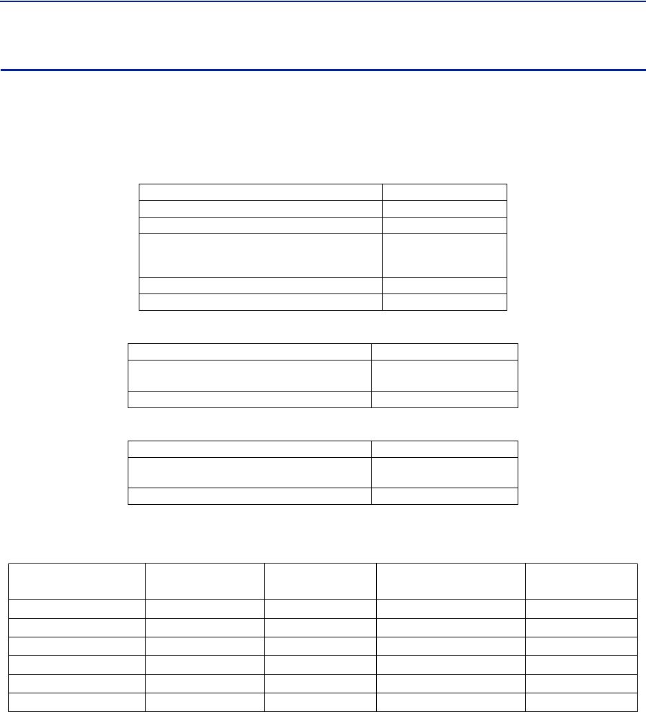
FiberDistributedAntennaSystem(FiberDAS)
31
DDU
Bird'sDistributedHighpowerradioheadisahighperformingwidebandradioheadequippedwithafeedforward
multicarrierpoweramplifierthatsupportsallmodulations.Thelightweight,convectioncooledIP65chassissecures
theperformanceinalmostanyenvironment.
FCC standards
Table 38 General Specifications
Table 39 Specifications DDU100 (Single Band)
Table 40 Specifications DDU200 (Dual Band)
Cellular Products
Table 41 Available Products, FCC/IC
Note: Allspecificationssubjecttochangewithoutnotice.
Class B Industrial Booster — ThisequipmentisaClassBIndustrialBoosterandisrestrictedtoinstallationas
anIn‐buildingDistributedAntennaSystem(DAS).
NoiseFigure,Typical 3dB
Delayexcludingopticalfiber <0.5µs
InstantaneousBandWidth,Max 15MHz
PowerSupply
Standard
Optional
85–264VAC
‐32to‐100VDC
OperatingTe mperatu re ‐25to55°C(32to113°F)
Casing IP65
PowerConsumption,max,typical225W
Dimensions,WxDxH11.8x5.1x27.6in.
30x13x70cm
Weight 31lbs(14kg)
PowerConsumption,max,typical 450W
Dimensions,WxDxH11.8x8.7x27.6in.
30x22x70cm
Weight 62lbs(28kg)
System UL Frequency MHz DL Frequency MHz Pout, DL,
dBm (RMS) Standard
LTELB 698‐716 728‐746 46 FCC/IC
LTEUB 777‐787 746‐756 46 FCC/IC
LTEFB 690‐716/777‐787 728‐756 46 FCC/IC
Cellular 824‐849 869‐894 46 FCC/IC
PCS1900 1850‐1915 1930‐1995 46 FCC/IC
AWS 1710‐1780 2110‐2180 46 FCC/IC

SystemDescription
32
Remote Unit Frequency Summary
Table 42 ETSI Bands
Table 43 FCC/IC Bands
Band 3GPP Band UL Frequency DL Frequency DDR Max
Composite
DDH Max
Composite
TETRA,PublicSafety 380‐385 390‐395 26 33
TETRA,Commercial 410‐415 420‐425 26 33
TETRA,Commercial 415‐420 425‐430 26 40
CDMA450 Band31 452.5‐457.5 462.5‐467.5 33 40
DD800 Band20 832‐862 791‐821 26 40
E‐GSM900 Band8 880‐915 925‐960 26 40
GSM1800 Band31710‐1785 1805‐1880 28 40
UMTS Band11920‐1980 2110‐2170 30 43
LTE2600 Band72500‐2570 2620‐2690 30 43
Band 3GPP Band UL Frequency DL
Frequency
DDR Max
Composite
DDS Max
Composite
(15MHz)
DDH Max
Composite
DDU Max
Composite
VHF 136‐174 136‐174 33 N/A N/A N/A
UHF 450‐470 450‐470 33 N/A N/A N/A
700Lower Band12 698‐716 728‐746 33 N/A 43 46
700UpperBand13&14 776‐806 746‐756 33 N/A 43 46
700Combined Band12,13&14 698‐716
776‐806 728‐75633414346
700PublicSafety 769‐775 799‐805 33 ‐‐N/A
800iDEN Band27 806‐824 851‐869334140N/A
850Cellular Band5824‐849 869‐89433414346
1900PCS Band25 1850‐1915 1930‐1995 33 41 43 46
AWS Band41710‐1755 2110‐2155 33 41 43 46
2600LTE Band72500‐2570 2620‐2690 33 N/A 43 N/A
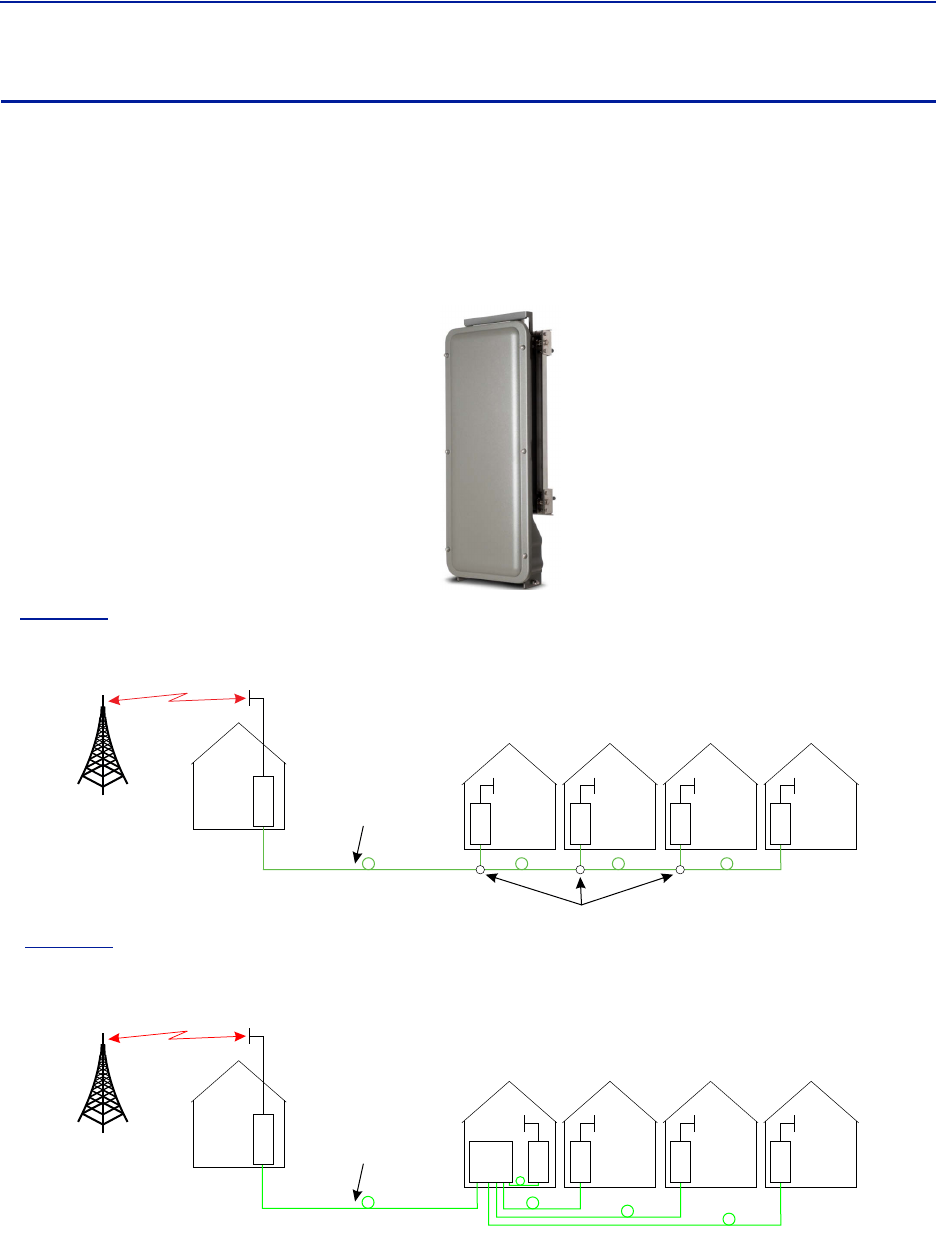
FiberDistributedAntennaSystem(FiberDAS)
33
DMU – Remote head end
Bird'sDMU100seriesisacompactheadendthatcanfunctionasalowpowerrepeaterorBTSinterface.Theunitcan
directlysupportupto4remotesorcanfiberfeedaHeadendMasterUnit.Remoteaccessisprovidedbyeitherthe
BirdRGWorviaEthernetconnection.Theunitisaruggedconvectioncooled,IP65chassisdesignedforoutdoor
locations.
ItispossibletobuildtheDMUtosupportmorethanoneband,however,thetypesofbandsandthenecessary
duplexersforaconfigurationmustbeverifiedtoensurecompatibilitywiththeRGW.
Figure 20 DMU – Remote Head End
In
Figure21
,theDMUisusedtopickupthesignalataremotelocationandthenitistransmittedonthefiberto
fourdifferentlocationsthatneedcoverage.TheRUcanbeconnectedtocoaxialspreadingnetworksifneeded.
Figure 21
DMU Feeding Remote Units
In
Figure22
,theDMUisfeedingaHeadendMasterUnitwhichinturnfeedstheRemoteUnits(RU).Thisisafar
moreflexiblesolutionandwouldbepreferredwhenpossible.
Figure 22
D
M
UHead
end R
UR
UR
UR
U
Fiber-Optic Cable
DMU Feeding BMU
TheDMUisequippedwithalowpoweruplinkamplifier.Theunitshouldbeusedinalocationthathasadequate
signalsothatpowerlevelofamobilephonewillsuffice.
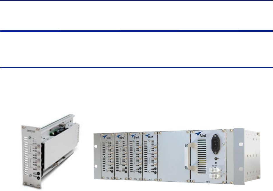
SystemDescription
34
Repeaters
BirdTech no lo giesoffersawidevarietyofrepeaterstoboostoffairsignals.Therepeatedsignalscanfeedpassive
DASorcanbeusedasaninputintotheactiveDAS.
DMR 400 Series Rack Mount Repeater
TheDMR400isdesignedtofitintheHeadendMasterFramealongwiththeBIUandFOIcards.Thesystemwas
originallydesignedtobeusedinmovingcoverageareassuchasshipsandtrainsthatrequireactivecontroloverthe
downlinkgain(linksymmetry)tocompensateforwidevariationsintheoff‐airsignals,butthesystemcaneasilybe
implementedintraditionalfixedlocationssuchasofficesandhospitals.
Figure 23 DMR 400 Rack Mount Repeater
AlthoughtheDMRrepeatersarerackmountedwiththeactiveDAScomponents,theDMRrepeatercanfunctionas
astandaloneunittoprovidecoveragetoapassiveDAS.
TheDMRrepeaterfamilyofferslinksymmetrysettings.Thisfunctionisusedtoautomaticallyadjusttheuplinkgain
basedonthedownlinksignal.Wheninstalledinmovingcoverageareassuchastrains,thefeaturepreventsthe
repeaterfromdesensitizingthedonorsitebyautomaticallycontrollinguplinklevels.
TheDMRrepeateralsooffersself‐oscillationprotection.Thisfunctionisusedtodetectproblemswithisolation
betweenthedonorandserviceantenna.Therepeaterwillinterveneandlowerthegaintoalevelequaltothe
isolationminusthestabilitymargin.ThesettingsareseparateforULandDL.
On/Off
Stabilitymargin:Valuesettingofhowmuchlowerthegainshouldbethanthecalculatedisolation.Rangeof
0.0to20.0dBm.
Recoverytime:Timethatshouldpassbeforetherepeaterresetthegaintothevaluespecifiedlevelin“RF
Config”(setgain).Rangeof30to86,400seconds.
Recoverymargin:Setvalueofgainlevelabovethegainspecifiedin“RFConfig”(setgain)thatisusedwhen
therepeaterrecoversafterthe“RecoveryTime”.Rangeof0.0to20.0dBm.
TheDMR400offersvariablebandwidthsupto35Mhz,dependingontheconfiguration.
RemoteaccesscanbeprovidedviaanEthernetconnectionorthroughtheBirdRemoteGateway.SNMPisa
standardontheunits.Noproprietarysoftwareisrequired.Operationalparametersaresetviaawebbrowser.
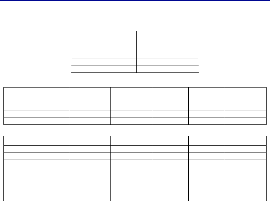
FiberDistributedAntennaSystem(FiberDAS)
35
Table 44 DMR400 Specifications
Table 45 Available Products, Cellular, FCC
Table 46 Available Products, Cellular, ETSI
Gain 50‐80dBmin1dBsteps
NoiseFigure‐Typical <5dB
Delay <6s
Dimensions 2cardslots
Weight(module) 0.7kg(1.5lbs)
OperatingTe mperatu re ‐25to55°C(13to131°F)
Band Uplink Downlink Pout, DL & UL Standard
DMR407 iDEN 806‐824 851‐869 28dBm FCC
DMR408 Cellular 824‐849 869‐894 28dBm FCC
DMR419 PCS1900 1850‐1915 1930‐1995 28dBm FCC
DMR420 AWS 1710‐1755 2110‐2155 28dBm FCC
Band Uplink Downlink Pout, DL & UL Standard
DMR401 TETRA,PublicSafety 380‐385 390‐395 20dBm ETSI
DMR402 TETRA,Commercial 410‐415 420‐425 20dBm ETSI
DMR403 TETRA,Commercial 415‐420 425‐430 20dBm ETSI
DMR404 CDMA450 453‐457.5 463‐467.5 25dBm FCC
DMR406 GSM‐R876‐880 921‐960 25dBm ETSI
DMR409 EGSM900 880‐915 925‐960 19dBm ETSI
DMR418 GSM1800 1710‐1785 1805‐1880 21dBm ETSI
DMR421 UMTS2100 1920‐1980 2110‐2170 23(DL)/20(UL) 3GPP
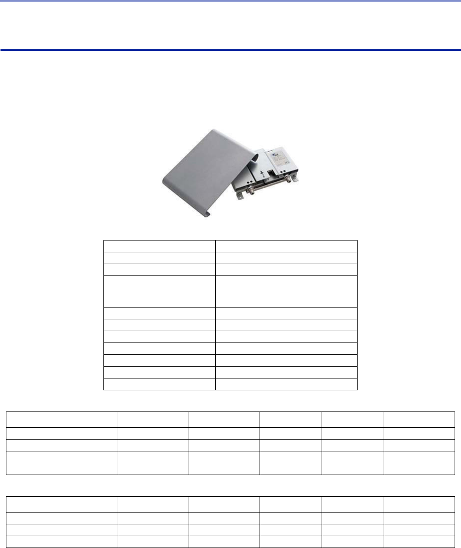
SystemDescription
36
DLR 600 Series Low Power Repeater
TheDLR600lowpowerrepeaterisdesignedforenvironmentswherelowsignallevelsarerequired.Althoughsmall,
theunitstilloffersBird’sfeaturerichfunctionssuchasself‐oscillationprotection,fastAGC,linksymmetry
functionality,SNMPandremoteaccessviaEthernetortheBirdRemoteGateway.
Figure 24 DLR 600 Low Power Repeater
Table 47 DLR600 Specifications
Table 48 Available Products, Cellular, FCC
Table 49 Available Products, Cellular, ETSI
Gain 40‐70dBmin1dBsteps
NoiseFigure <5dB
Delay <6s
PowerSupply
Standard
optional
100to240VAC
12to28VDC
Dimension(WxDxH) 30x5x21cm(11.8x2x8.3inches)
Weight <1.4Kg(3.1lbs)
OperatingTe mp(DC) ‐25to55°C(13to131°F)
OperatingTe mp(AC) 0to+40°C(+32to+104°F)
Casing IP42
Bandwidth 0‐15MHz
Connectors SMAorN‐type
Band Uplink Downlink Pout, DL & UL Standard
DLR607 iDEN 806‐824 851‐869 16dBm FCC
DLR608 Cellular 824‐849 869‐894 16dBm FCC
DLR619 PCS1900 1850‐1915 1930‐1995 16dBm FCC
DLR620 AWS 1710‐1755 2110‐2155 16dBm FCC
Band Uplink Downlink Pout, DL & UL Standard
DLR609 EGSM900 880‐915 925‐960 13dBm ETSI
DLR618 GSM1800 1710‐1785 1805‐1880 23dBm ETSI
DLR621 UMTS2100 1920‐1980 2110‐2170 15dBm 3GPP
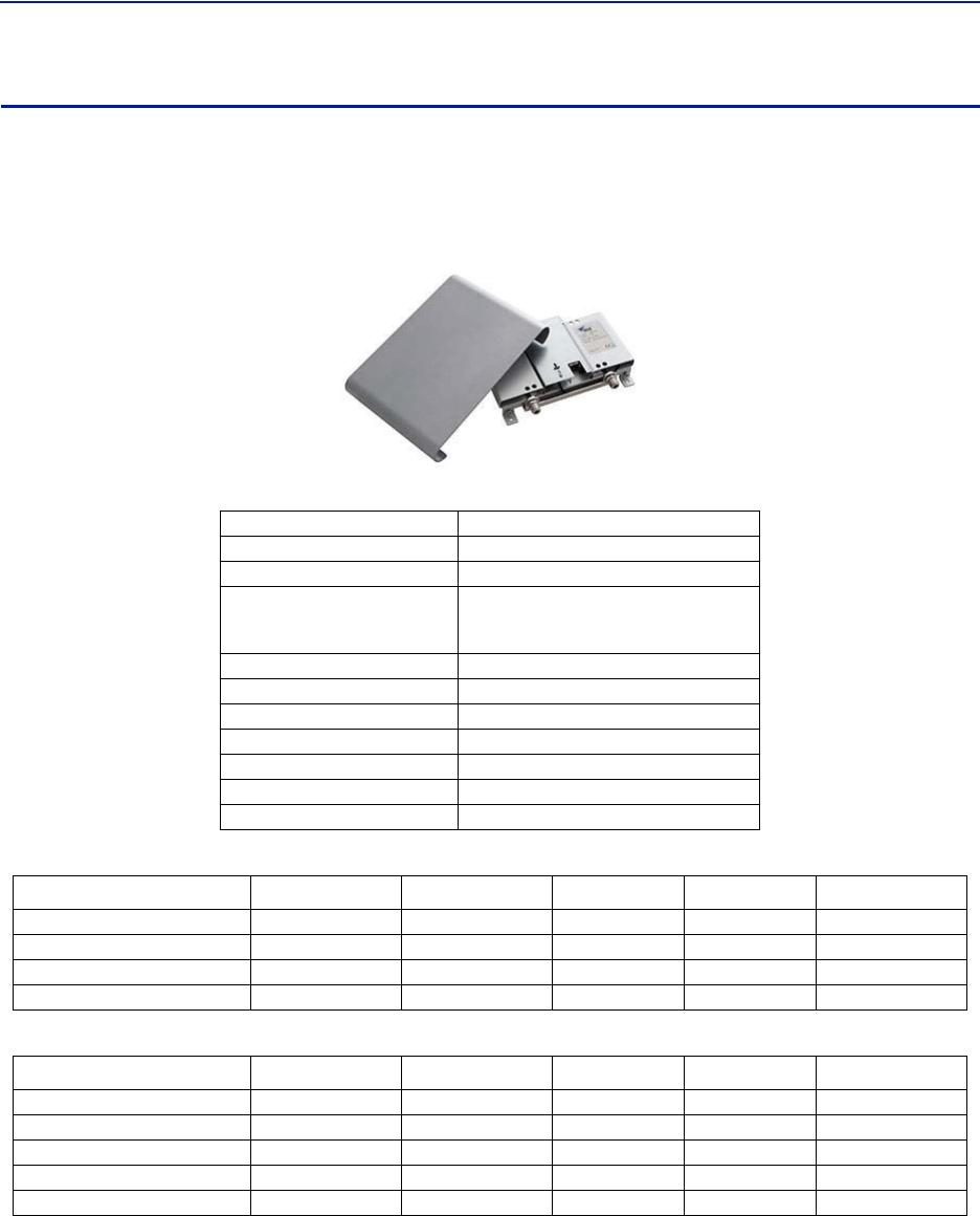
FiberDistributedAntennaSystem(FiberDAS)
37
DMR600 Series Medium Power Repeater
TheDMR600isamediumpowerrepeaterwithbandselectivecapabilities.Althoughsmall,theunitstilloffers
Bird'sfeaturerichfunctionssuchasself‐oscillationprotection,fastAGC,linksymmetryfunctionality,SNMPand
remoteaccessviaEthernetortheBirdRemoteGateway
Figure 25 DMR 600 Low Power Repeater
Table 50 DMR600 Specifications
Table 51 Available Products, Cellular, FCC
Table 52 Available Products, Cellular, ETSI
Gain 50‐80dBmin1dBsteps
NoiseFigure <5dB
Delay <6s
PowerSupply
Standard
optional
100to240VAC
12to30VDC
Dimension(WxDxH) 30x5x21cm(11.8x2x8.3inches)
Weight <1.4Kg(3.1lbs)
OperatingTe mp(DC) ‐25to55°C(13to131°F)
OperatingTe mp(AC) 0to+40°C(+32to+104°F)
Casing IP42
Bandwidth 35MHz
Connectors SMAorN‐type
Band Uplink Downlink Pout, DL & UL Standard
DMR607 iDEN 806‐824 851‐869 16dBm FCC
DMR608 Cellular 824‐849 869‐894 16dBm FCC
DMR619 PCS1900 1850‐1915 1930‐1995 16dBm FCC
DMR620 AWS 1710‐1755 2110‐2155 16dBm FCC
Band Uplink Downlink Pout, DL & UL Standard
DMR604 CDM450 453‐457.5 463‐467.5 25dBm FCC
DMR606 GSM‐R876‐880 921‐925 19dBm ETSI
DMR609 EGSM900 880‐915 925‐960 19dBm ETSI
DMR618 GSM1800 1710‐1785 1805‐1880 29dBm ETSI
DMR621 UMTS2100 1920‐1980 2110‐2170 23(DL)/20(UL) 3GPP
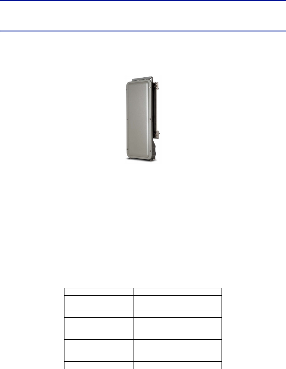
SystemDescription
38
DHR 800 Series High Power Repeater
TheDHR800offersahighpowersolutioninalightweight,convectioncooledIP65chassis.TheunitoffersBird's
featurerichfunctionssuchasself‐oscillationprotection,fastAGC,linksymmetryfunctionality,SNMPandremote
accessviaEthernetortheBirdRemoteGatewayallinaruggedIP65chassis.
Figure 26 DHR 800 Series High Power Repeater
TheDHRrepeaterfamilyofferslinksymmetrysettings.Thisfunctionisusedtoautomaticallyadjusttheuplinkgain
basedonthedownlinksignal.Wheninstalledinmovingcoverageareassuchastrains,thefeaturepreventsthe
repeaterfromdesensitizingthedonorsitebyautomaticallycontrollinguplinklevels.
TheDHRrepeateralsooffersself‐oscillationprotection.Thisfunctionisusedtodetectproblemswithisolation
betweenthedonorandserviceantenna.Therepeaterwillinterveneandlowerthegaintoalevelequaltothe
isolationminusthestabilitymargin.ThesettingsareseparateforULandDL.
On/Off
Stabilitymargin:Valuesettingofhowmuchlowerthegainshouldbethanthecalculatedisolation.Rangeof
0.0to20.0dBm.
Recoverytime:Timethatshouldpassbeforetherepeaterresetthegaintothevaluespecifiedlevelin“RF
Config”(setgain).Rangeof30to86,400seconds.
Recoverymargin:Setvalueofgainlevelabovethegainspecifiedin“RFConfig”(setgain)thatisusedwhen
therepeaterrecoversafterthe“RecoveryTime”.Rangeof0.0to20.0dBm.
Table 53 DHR800 Specifications
Gain 50‐88dBmin1dBsteps
NoiseFigure <5dB
Delay <6s
PowerSupply 85to264VAC
PowerConsumption <130W
Dimension(WxDxH) 30x13x70cm(11.8x5.1x27.6inches)
Weight <12kg(26.4lbs)
OperatingTe mp ‐25to55°C(13to131°F)
Casing IP65
Bandwidth 35MHz
Connectors N‐typeorDIN7/1 6

FiberDistributedAntennaSystem(FiberDAS)
39
Table 54 Available Products, Cellular, FCC
Table 55 Available Products, Cellular, ETSI
Bird Repeater Frequency Summary
Table 56 ETSI Bands
Table 57 FCC Bands
Band Uplink Downlink Pout, DL & UL Standard
DHR807 iDEN 806‐824 851‐869 33(DL)/25(UL) FCC
DHR808 Cellular 824‐849 869‐894 33(DL)/25(UL) FCC
DHR819 PCS1900 1850‐1915 1930‐1995 33(DL)/25(UL) FCC
DHR820 AWS 1710‐1755 2110‐2155 33(DL)/25(UL) FCC
Band Uplink Downlink Pout, DL & UL Standard
DHR801 TETRA,PublicSafety 380‐385 390‐395 26(DL)/20(UL) ETSI
DHR802 TETRA,Commercial 410‐415 420‐425 26(DL)/20(UL) ETSI
DHR803 TETRA,Commercial 415‐420 425‐430 26(DL)/20(UL) ETSI
DHR804 CDMA450 453‐457.5 463‐467.5 33(DL)/25(UL) FCC
DHR806 GSM‐R876‐880 921‐960 26(DL)/19(UL) ETSI
DHR809 EGSM900 880‐915 925‐960 26(DL)/19(UL) ETSI
DHR818 GSM1800 1710‐1785 1805‐1880 28(DL)/21(UL) ETSI
DHR821 UMTS2100 1920‐1980 2110‐2170 30(DL)/21(UL) 3GPP
DL Frequency UL Frequency DMR
400
DLR
600
DMR
600
DHR
800
TETRAPublicSafety390‐395380‐385
TETRA,Commercial420‐425410‐415
TETRA,Commercial425‐430415‐420
CDMA450463‐467.5453‐457.5
GSM‐R921‐925876‐880
EGSM900925‐960 880‐915
GSM18001805‐18801710‐1785
UMTS2110‐21701920‐1980
DL Frequency UL Frequency DMR
400
DLR
600
DMR
600
DHR
800
PublicSafety800851‐869806‐824
Cellular850869‐894824‐849
PCS19001930‐1995 1850‐1915
AWS2110‐21551710‐1755
40
Chapter 3 Installation guidelines
ForCMRS817‐824MHzApplicationsandAmericanCellularApplications:
Thisdevicecomplieswithpart15oftheFCCrules.Operationissubjecttothefollowingtwoconditions:(1)This
devicemaynotcauseharmfulinterferenceand(2)thisdevicemustacceptanyinterferencereceived,including
interferencethatmaycauseundesiredoperation.
ForinstallationssubjecttoIndustryCanadacertification:
Health and Safety
BirdDASsystemisanadvancedsystemandshouldbehandledbyskilledstaff.Birdishappytooffertrainingof
installationserviceprovidersinthecasethisisnecessary.
Readallavailabledocumentationandwarningsbeforehandlingtheequipment.Equipmentfailuresduetoimproper
handlingarenormallynotcoveredbytheproductwarranty.
Respectallwarningsignsontheequipmentandinthedocumentation.Makesuretoonlyoperatetheequipmenton
frequenciesallowedtouse.Donotmodifytheequipment.
TheequipmentcontainsaClass3BlaserandtheequipmentisClass1.DoneverlookintotheLaserbeamdirectlyor
indirectly,itisstronginvisiblelightandmaycauseseriousdamagetohumaneyes.
Alwaysuseprotectivecapsonfiberandconnectorendswhenfiberisremovedfromsocket.Alwayscleansocketand
connectorafterafiberhasbeenremovedbeforeitisreconnected.
Makesuretokeeppasswordsandotheroperationalinformationawayfromunauthorizedpersonnel.
WARNING
ThisisNOTaconsumerdevice.
ItisdesignedforinstallationbyFCCLICENSEESandQUALIFIEDINSTALLERS.YouMUSThaveanFCCLICENSEor
expressconsentofanFCClicenseetooperatethisdevice.YouMUSTregisterClassBsignalboosters(asdefinedin
47CFR90.219)onlineatwww.fcc.gov/signal‐boosters/registration.Unauthorizedusemayresultin
significantforfeiturepenalties,includingpenaltiesinexcessof$100,000foreachcontinuingviolation.
WARNING
ThisisNOTaconsumerdevice.
ItisdesignedforinstallationbyFCCLICENSEESandQUALIFIEDINSTALLERS.YouMUSThaveanFCCLICENSEor
expressconsentofanFCClicenseetooperatethisdevice.Unauthorizedusemayresultinsignificantforfeiture
penalties,includingpenaltiesinexcessof$100,000foreachcontinuingviolation.
WARNING
ThisisNOTaconsumerdevice.
ItisdesignedforinstallationbyaninstallerapprovedbyanISEDlicensee.
YouMUSThaveanISEDLICENCEortheexpressconsentofanISEDlicenseetooperatethisdevice.
WARNING
Avoidlookingintoconnectedfibersandreceptacles.
ThelaserusedinthissystemisaClass3blaserthatproducesinvisibleinfra‐redcoherentlight.Notsafetoview
withopticalinstruments.Alwaysputtheprotectioncapsonunusedfibersandreceptacles.

FiberDistributedAntennaSystem(FiberDAS)
41
Cable Routing/Antenna Selection
Ensureallcables,e.g.powercable,fiber‐opticcable,Antennacablesareroutedandsecuredinaccordancewith
local/nationalrequirementswhileavoidingdamagetothecables.
AntennasandcoaxcablesareselectedaspartoftheDASsystemdesignandmayvarywithlocation,frequency,and
powerlevelrequirements.
Useonlyauthorizedandapprovedantennas,cablesand/orcouplingdevices.Theuseofunapprovedantennas,
cablesorcouplingdevicescouldcausedamageandmaybeofviolationofFCCregulations.
EachindividualantennausedwiththeDASmustbeinstalledtoprovidetheseparationdistanceasspecifiedinthe
RFexposurerequirements(refertospecificRemoteUnitRFExposurelimitsinthesystemdescriptionsection).
Antenna Installation
TheBirdFiberDASsystemsdonotincluderemoteorheadendantenna.Theremoteendantennamustbeselected
duringsystemdesign,theantennamanufacturer’sdatawillberequiredwhencalculatinglinkbudgets.
Antennainstallationinstructionsareprovidedbytheantennamanufacturer.
ExternaldonorantennasthataremostcommonlyusedincombinationwithDDRorDDHRemoteUnitfamilyfor
outdoorenvironmentare17dBigainantennas.
Safety and Care for Fibers
Everytimeafiberisdisconnectedandre‐connectedcareshouldbetakentoavoidgettingdustontheconnectoror
inthereceptacle.Cleanwithadryfibercleaningtoolbeforereconnectingthefiberatalltimes.Asinglespeckof
dustcanseverelyimpactthetransmission.Donottouchthefiberendswithyourfingers.Thatwillleavegreaseon
theconnectorsandmaycausesevereproblems.
CAUTION
Unauthorizedantennas,cables,and/orcouplingdevicesmaycausenon‐conformitywithnationalorinternational
regulations,couldcausedamage,ornon‐conformingERP/EIRP.
WARNING
Avoidlookingintoconnectedfibersandreceptacles.
ThelaserusedinthissystemisaClass3blaserthatproducesinvisibleinfra‐redcoherentlight.Notsafetoview
withopticalinstruments.Alwaysputtheprotectioncapsonunusedfibersandreceptacles.

Installationguidelines
42
Tools and Material Requirements
Fiber Optics
Allfiberopticcables,includingpatchcords,mustbeSINGLEMODE.Multi‐modefiberisnotsupported.
BirdequipmentisdesignedtobeusedwithonlySC/APCfiberconnectors.Allconnectionpointsinthefibermust
eitherbefusionsplicedorequippedwithAPCconnectors.UPCconnectorsanywhereinthefiberpathwillcause
degradationintheperformanceoftheequipment.APCconnectorscanbeidentifiedbytheirgreenjacket.
Tota lopticallossmustbe<15dBo.
Opticalreturnloss‐60dBorgreater.
Fiberpanelinserts/couplingsmustbeAPC.
Tools
FiberOpticcleanerforSC/APCconnectors
T8Torxbitforcardcagemodules
Appropriatebitforrackscrews
SpectrumanalyzerwithRFpowermeter
AppropriatejumpercablestoconnectspectrumanalyzertoBirdequipment
OTDR
Opticalpowermeter
Opticalvisualfaultfinder
Fibersplicer
SMAtorquewrenchcalibrateto0.9N‐m
ESDStrap‐(ElectrostaticDischarge):TheBIU,FOIandPowerSuppliescontainhighlysensitivecomponents
thatcanbedestroyedbystatic.
NEVERopencards,BGW,CGW,repeatersorremotes!
Miscellaneous Material
ACpowercord(s)ifusingtheDPU‐301powersupply[ACtoDCpowersupply]
18AWGpowerwireifusingtheDPU‐302powersupply[DCtoDCpowersupply]
FerritebeadfilterfortheDCsupplycabletotheDPU‐302.Theferritebeadfiltermustbeinstalledcloseto
theDPU‐302.Followmanufacturerrecommendationsforproperinstallationoftheferritebeadfilter.
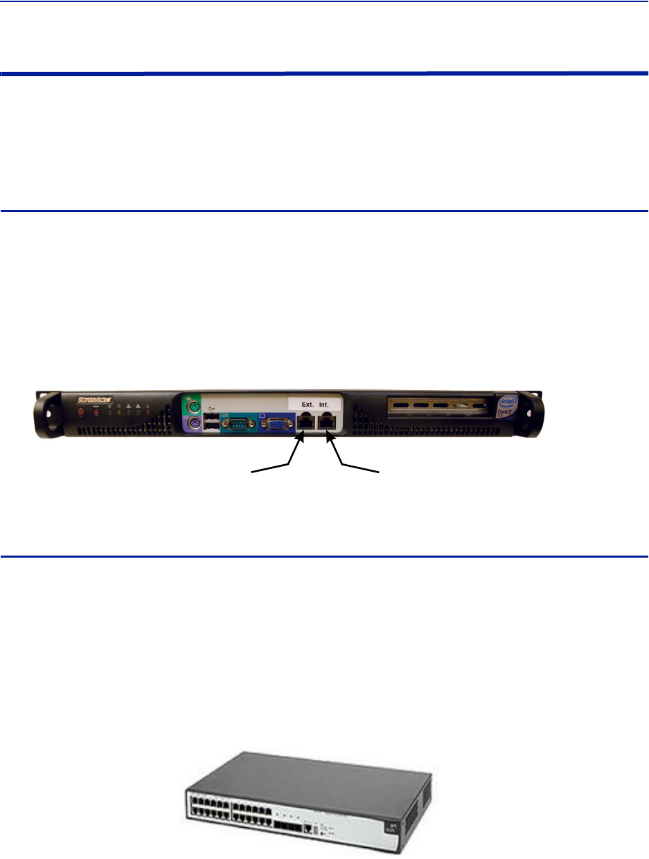
FiberDistributedAntennaSystem(FiberDAS)
43
Installing Headend Equipment
Allequipmentmustbeproperlygrounded.Groundpeginthemainconnectorforbothhead‐endgear(MasterUnit)
andremotegear(RemoteUnits)mustbeconnectedtoPhase,NeutralandGroundinaproperwaybeforepoweris
connected.
Thechassisoftheremoteandtherackofthemasterunitshouldbegroundedtoapotentialbarorsafetygrounding
barwhenoperated.Allelectricalinstallationsshouldbedonebyacertifiedelectricianonly.
BGW
TheBGWisdesignedtobeinstalledina19"rack.
TheBGWistypicallymountednearthetopoftherack.
ConnectpowertoanavailableNEMA5‐15Rreceptacle.
UsinginstallerprovidedEthernetcable,connectthe“Ext”porttotheappropriateback‐haulconnection.
Theback‐haulconnectioncanbeDSL,offairmodem,LAN,WAN.SeeBGWsetupinstructions.
Figure 27
Back-haul Connection
(LAN, WAN, ETC)
Connect to Head end
Ethernet Switch, Port 25
BGW Installation, Ethernet Connections
Ethernet Switch
TheEthernetswitch,ETH,isdesignedtobeinstalledina19"rack.
PlacementistypicallybetweentheBGWandtheMasterFrameUnit.Placementconsiderationshould
includeproperroutingofEthernetcablesandtheinstallationofadditionalcablesaftertheinitial
installationiscomplete.MountingmaywithEthernetportstothefrontorrearoftherack.
ConnectpowertoanavailableNEMA5‐15Rreceptacle.
UsinginstallerprovidedEthernetcable,connectport25oftheEthernetswitchtothe“INT”portonthe
BGW.
Figure 28 Ethernet Switch
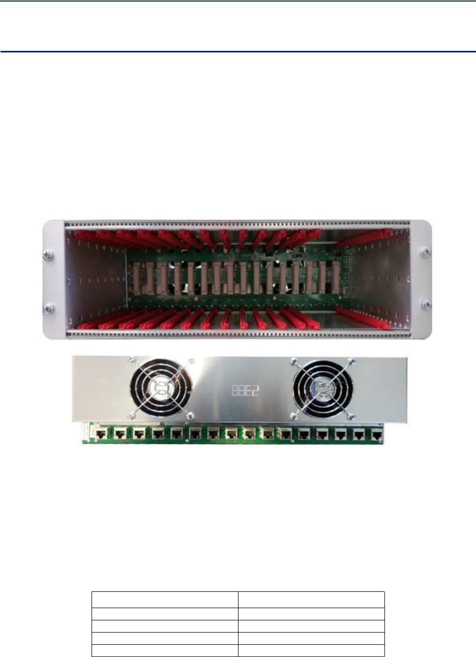
Installationguidelines
44
Master Unit
TheMasterUnitisdesignedtobeinstalledina19"rack.
Beforeinstalling,considercableroutingforallcardstobeinstalledintheMasterUnit.Theinstallermay
wanttoconsiderhorizontalcablemanagerstobemountedaboveandbelowtheMasterUnittoaidinthe
installationandongoingmaintenanceofthesystem.
EachcardintheMasterUnitwillrequireanEthernetconnectiontotheBGWinordertobeprogrammed
andmonitored.InstallcontractorprovidedEthernetcablebetweentheappropriateEthernetportandthe
Ethernetswitch.
Note: TheportnumberontheMasterUnitisinreverseorderonthebackoftheMasterUnit.
Figure 29 Ethernet Port Numbering, Front and Rear Views
1
1
2
2
3
3
4
4
5
5
6
6
7
7
8
8
9
9
10
10
11
11
12
12
13
13
14
14
15
15
16
16
OnlytheactiveportontheMasterUnitrequiresanEthernetconnection.
Example:TheBIUwillconsumetwoslotsintheMasterUnit.Ifinstalledinslots#1and#2,only
slot#1willmakephysicalconnectiontothebackplane.InstallanEthernetcableonthebackof
theMasterUnitinport#1toprovidetheBIUwithBGWconnectivity.
AllopenslotsontheMasterUnitrequireablankcoverplatetoallowforproperaircirculation.Blank
platesmustbeorderedseparately.
Table 58 Available Blank Cover Plates
Part Number Slots Covered
DB101 1Slot
DB102 2Slots
DB103 3Slots
DB104 4Slots
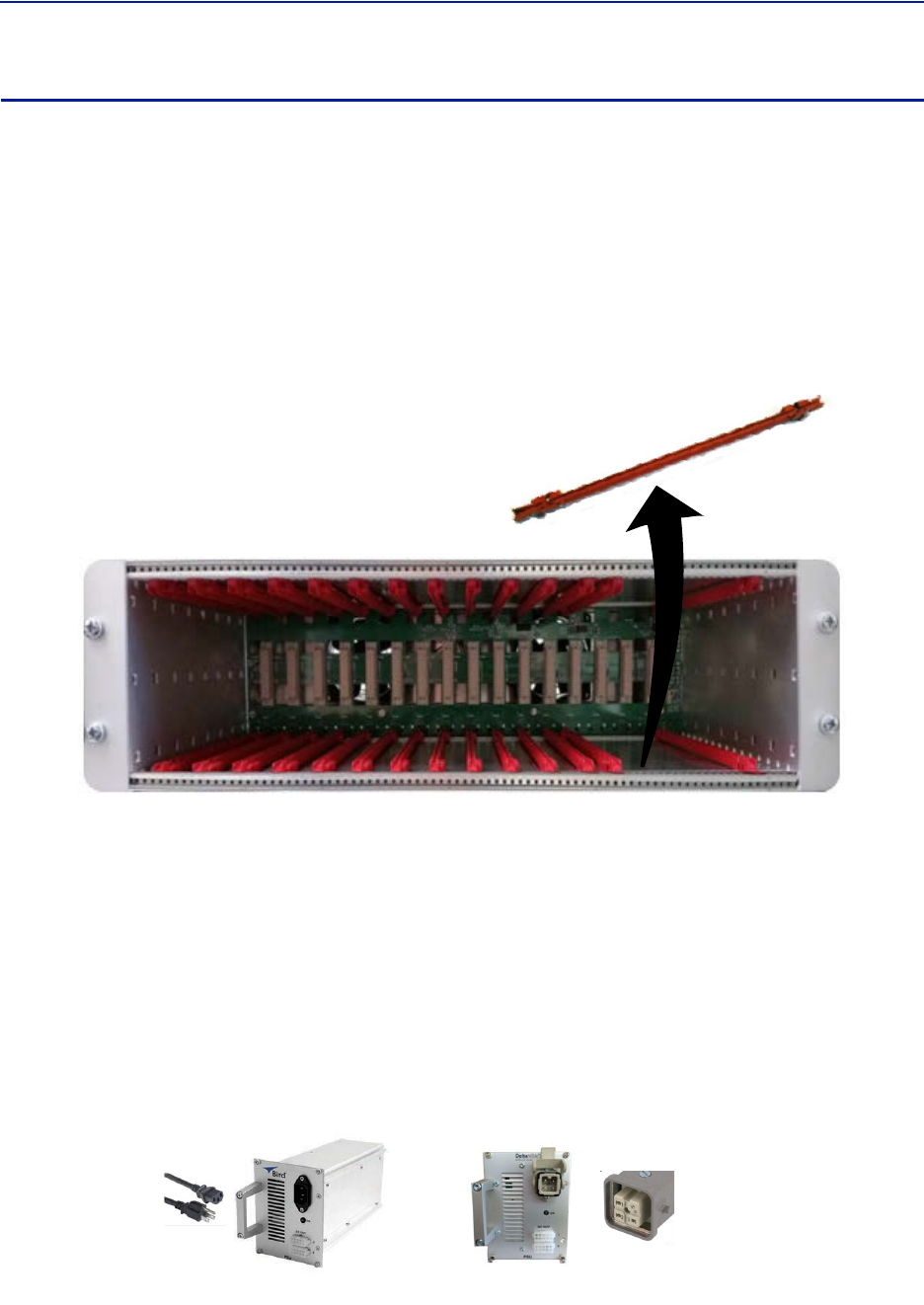
FiberDistributedAntennaSystem(FiberDAS)
45
Power Supply Unit
BirdTech no lo giesofferstwodifferentpowersuppliesfortheMasterUnit:AC(DPU‐301)andDC(DPU‐302).The
powersupplycanbelocatedinaMasterUnitotherthantheoneitispowering.Eachpowersupplyisshippedwith
oneMolexpowersupplyjumper.Ifredundantpowersuppliesarerequiredadditionalpowersupplyjumper(s)will
needtobeordered.
ThepowersupplyusesfourslotsontheMasterUnit.
PriortoinstallingthePSUintheMasterUnitchassistheredsliderailsmustbecarefullyremovedfromthe
slotsthatthePSUwilloccupy.
Figure 30 Slide Rail Removal
PSU DPU-301
TheACDPU‐301powersupplyhasastandardC13receptacle.
TheACDPU‐301hasaninputrangefrom86‐264VACwith50or60Hz.
Duetosite‐specificneedsonlengthandvaryingstandardsofACplugtypes,theACpowercorddoesnot
shipwiththeequipment.TheinstallationcontractormustprovidetheACpowercord.
TheDPU‐301cansupportasingle,fullyloadedMasterFrameUnitwithupto16cards(BIU,FOI,ICU).Thecards
maybeallofonetypeoramixtureoftypes.
Figure 31
DPU-301 DPU-302
Power Supply Units
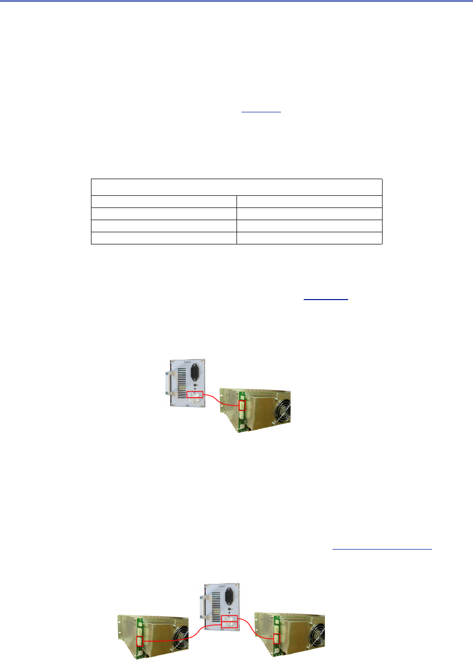
Installationguidelines
46
PSU DPU-302
TheDPU‐302usesaHANfourprongHeavyDutyPowerConnector.
TheDCtoDCDPU‐302powersupplyhasininputratingof‐36VDCto‐72VDC.
TheDPU‐302requirestheinstallertoprovide18AWGwirefortheHAN3Aplugkit(HartingP/N1020003
0002)thatisprovidedwiththepowersupply.See
Table59
forconnectorpinout.
TheDCpowersupplycansupportasingleMasterFrameUnitwithupto12cards(BIU,FOI,ICU).Thecardsmaybe
allofonetypeoramixtureofcards.
Table 59 DPU-302 Connector Pinout
Primary Power Configuration
ConnecttheoutputofthepowersupplytotheinputoftheMasterUnit.
UseP101ontheMasterUnitasthemainpowersupplyfeed.See
Figure32
.
Note: NotethatalthoughtherearetwooutputconnectionsonthefrontofthePSU,thePSUcanonly
poweroneMasterFrameatatime.
Figure 32 Primary Power Configuration
Primary Power for One Master Unit
Backup Power Configuration
Itisnotrequiredtouseabackup/redundantpowersupply,butiftheprimaryPSUfailsabackupPSUwillallowthe
unittocontinueoperatingwithoutcausinganoutage.
Thesystemdesignermayelecttohaveasingle,redundantPSUactasabackuptotwodifferentMasterUnits
simultaneouslywiththeunderstandingthatifthemainPSUforeachMasterUnitfailsduringthesametimeperiod
thatthebackup/redundantPSUcan'tsupportbothMasterUnits.
UseP102ontheMasterUnitforabackup/redundantpowersupply.See
Figure33onpage46
.
Figure 33 Backup Power Configuration
Backup Power for Two Master Units
Han 3A Pinout
Pin#1 (+)Positive
Pin#2 Notconnected
Pin#3 (‐)Negative
Pin#4 Earth/Ground
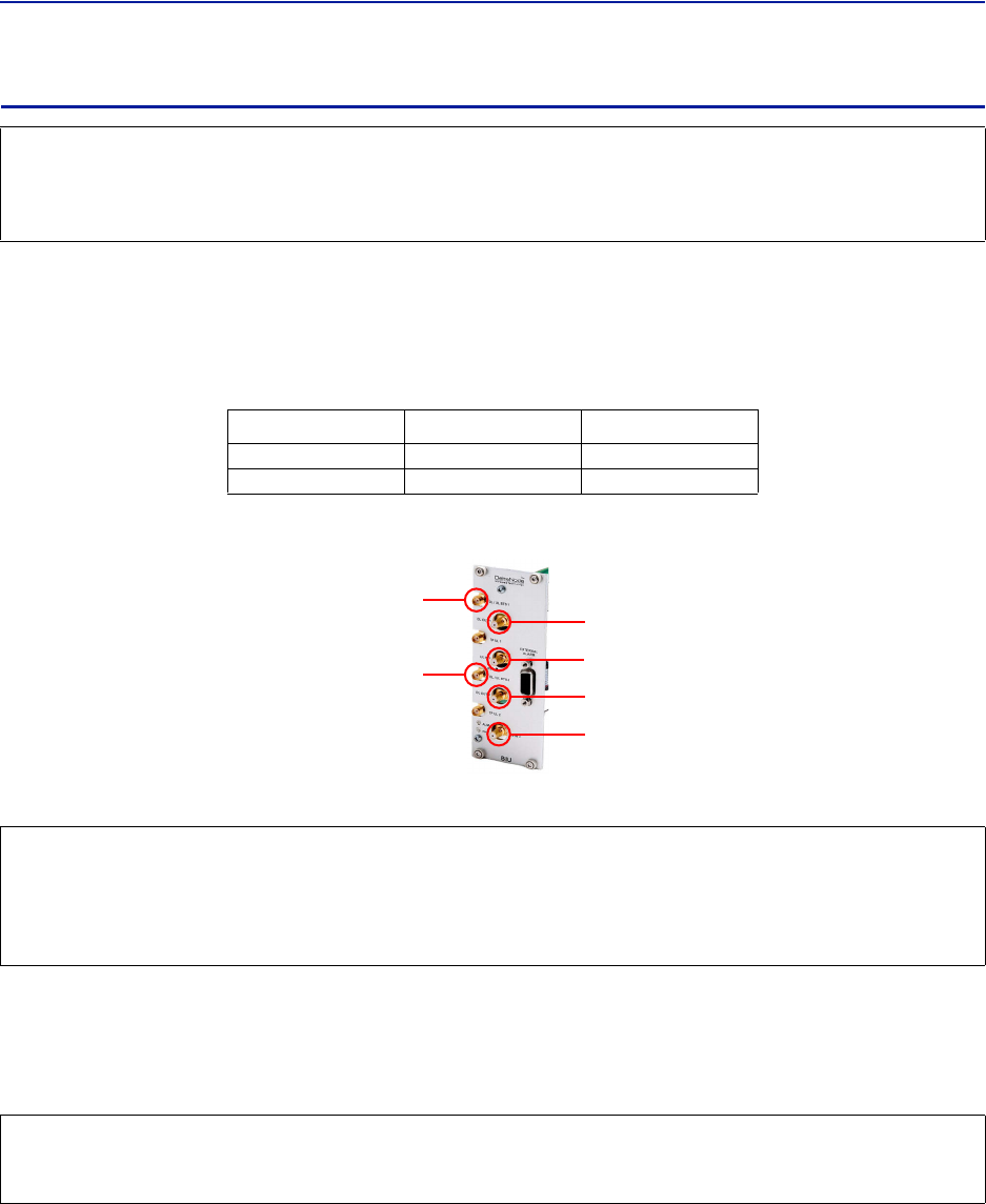
FiberDistributedAntennaSystem(FiberDAS)
47
BIU
TheBIUservesastheRFinterfacebetweentheRFsourceandtheICU/FOI.EachBIUispre‐settoafrequencyband
andisnotfieldtunable.
TheBIUhastwosetsofRFsourceconnections.Theunitscanaccepttwoindependentfeeds(withinthesameband).
ThefeedscanbefromseparatesourcesorAandBpathsinaMIMOconfiguration.
DuetothehighlevelofRFcomingintoBIU,useonlyqualityRFcables.
Figure 34 BIU Connections
RF
Source ICU
or
FOI
InstalltheBIUintheMasterUnit.TheBIUusestwoslotsintheMasterUnit.
Note: TheUL1andUL2uplinktestportsare3dBlowerthanthesignalonthecorrespondingDL/UL
BTSport.
ConnectSMAtotheRFsource.Tightento8in‐pounds(0.9N‐m)withacalibratedtorquewrench.
ConnectQMAtotheICU/FOI.
CAUTION
OverdrivingtheRFsourceinputintotheBIUwillcausepermanentequipmentfailureandwillvoidthewarranty.
Theinstallermustensurethatinputlevelsarenotexceeded.PlanformaximumpoweroutoftheRFsourceand
attenuateaccordinglywithexternalattenuatorsifneeded.
BIU Type Minimum DL Input Maximum DL Input
LowLevel ‐7dBm +7dBm
HighLevel +20dBm +33dBm
CAUTION
WhenmatingRFconnectors,ensurethattheyareproperlyalignedandnotcrossthreaded.
TightenSMAconnectorsto8in.‐lbs(0.9N‐m).
DoovertorqueRFconnectors,thiscouldresultindamagetotheUnit.
DonotundertorqueRFconnectors,thiscouldresultinpoorsignaltransmission.
CAUTION
ExcesstensiononthecableorconnectorsmaycausePIMissues.
Cablesmustbesecuredintherackwithoutapplyingtensiontotheconnectors.
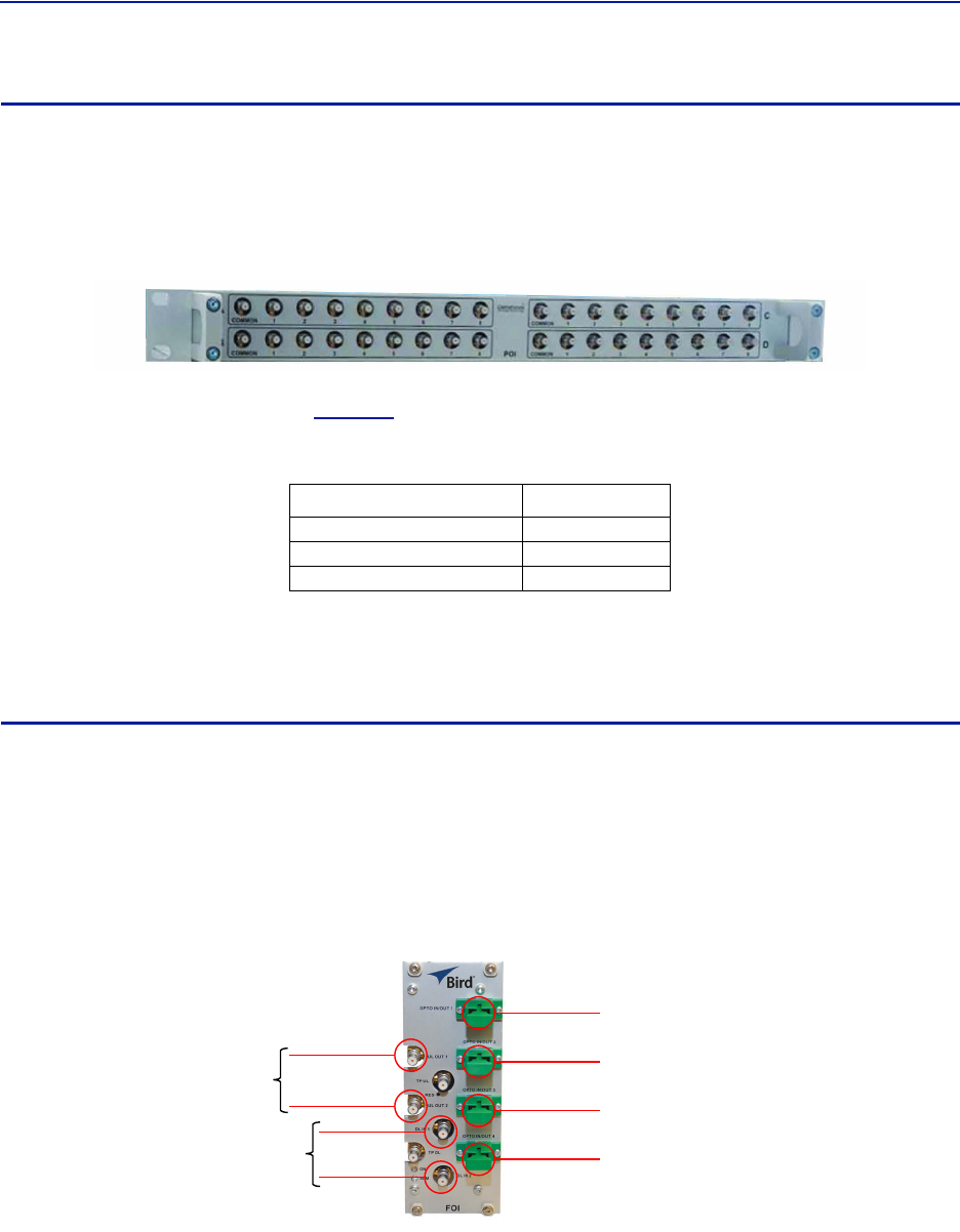
Installationguidelines
48
ICU
TheICUisdesignedtobeinstalledina19"rack.
TheICUistypicallyinstalleddirectlyaboveorbelowtheMasterUnitchassis.Considerpostinstallation
changesandtestingwhenselectingaslottoinstalltheICU.
Figure 35 ICU
TheICUhasQMAconnectors.QMAcablekit‐BirdpartnumberDCC320isavailableforusewiththeICU.Thekit
contains32QMAtoQMAcables(see
Table60
)thatcanbeusedtopatchbetweentheBIUtotheICU,BIUtothe
FOIorICUtoFOI.
Table 60 QMA Cable Kit
TheICUisconfiguredwithtwoidenticalpaths‐uplinkanddownlink.Thetypicalconfiguration[DIU301(88MHzto
2700MHz)]isfour1:8splitters/combiners(twoforULandtwoforDL).NotethatthetheoreticallossforeachDIU301
is35dBm.
FOI
TheFOIismountedintheMasterUnitchassis.TheFOIusesoneslotintheMasterUnit.
TheRFconnectionsareQMA.
ThefiberconnectionsareSC/APC.
TheFOIcanbeorderedwithanoptionalDCC330jumperkit.ThekitcontainstwoSC/APCjumpersthatare5meters
(16.4feet)inlength.
Figure 36 FOI Connections
OPTO IN/OUT
for
Remote Units
Uplink
Downlink
Length Quantity
250mm(9.8”) 13
350mm(13.8”) 13
500mm(19.7”) 6
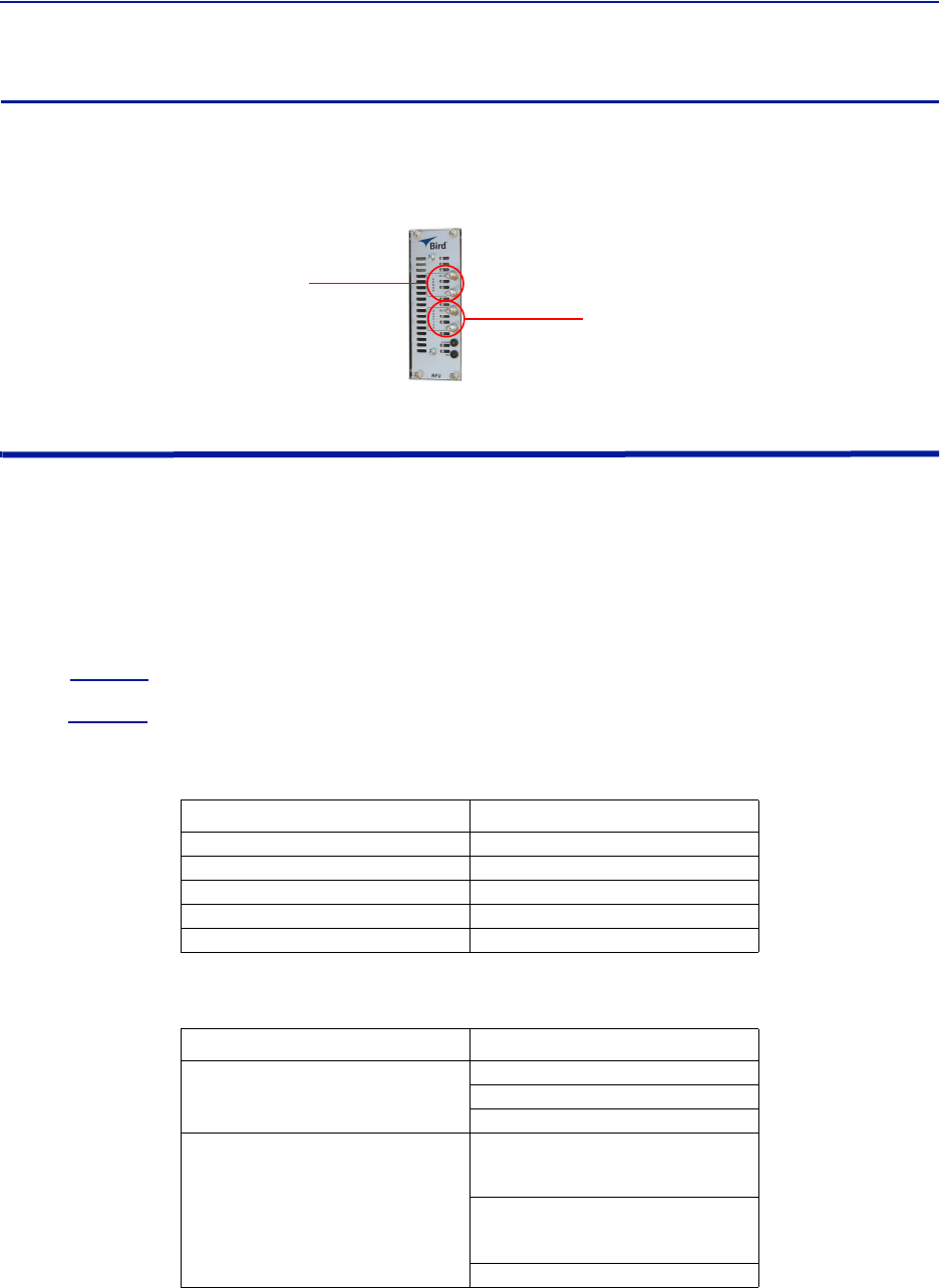
FiberDistributedAntennaSystem(FiberDAS)
49
RFU
Theintegratedrepeaterunit,RFU,DMR400ismountedintheMasterUnitchassis.TheDMR400usestwoslotsinthe
MasterUnit.
Figure 37
Rebroadcast
Uplink/
Downlink
RF
Source
RFU Connections
Powering Up the Head End
1. ApplypowertotheBGWbypressingthepowerbuttonontheleftsideoftheunit.
TheBGWrequiresapproximately5minutestocompletelybootup.DuringtheBGWbootprocess,themodules
intheMasterUnitwillflashRedandGreen.
2. ApplypowertotheEthernetSwitchandtheMasterUnit.
3. VerifyBGWbootcycleiscomplete,
Note: TheBGWwillhavegreenLED'slitevenwhenpoweredoff.ThisispartoftheLANwakeupfea‐
ture.WhentheBGWisrunningtherewillbethreeLED'slitandtheharddriveiconshowingactivity.
4. See
Table61
fortheLEDalarmcodesforthemodulesintheMasterUnit.
AftertheBGWbootprocessiscomplete,allmodulesintheMasterUnitshouldhavesomeLEDindication.Ifnot,
see
Table62
.
Table 61 Master Unit Module LED Indicators
Table 62 Master Unit Troubleshooting
Status LED Indication
Normal Green‐slowflash
IncomingAlarm SolidRed‐Limitedto5seconds
Warning RedLEDflashes1Hz1/8dutycycle
Error RedLEDflashes2Hz¼dutycycle
Critical RedLEDremainssolid
Malfunction Corrective Action
If no modules have LED indications
CheckPowercabletoPSU.
CheckpowersourceforMasterUnit.
CheckconnectionfromPSUtoChassis.
If a module does not have LED ON
Indicator
Verifythemoduleisproperlyseatedinto
thechassis.
Moveamoduletoanotherslotonthe
MasterUnitchassis.
Replacemodule.
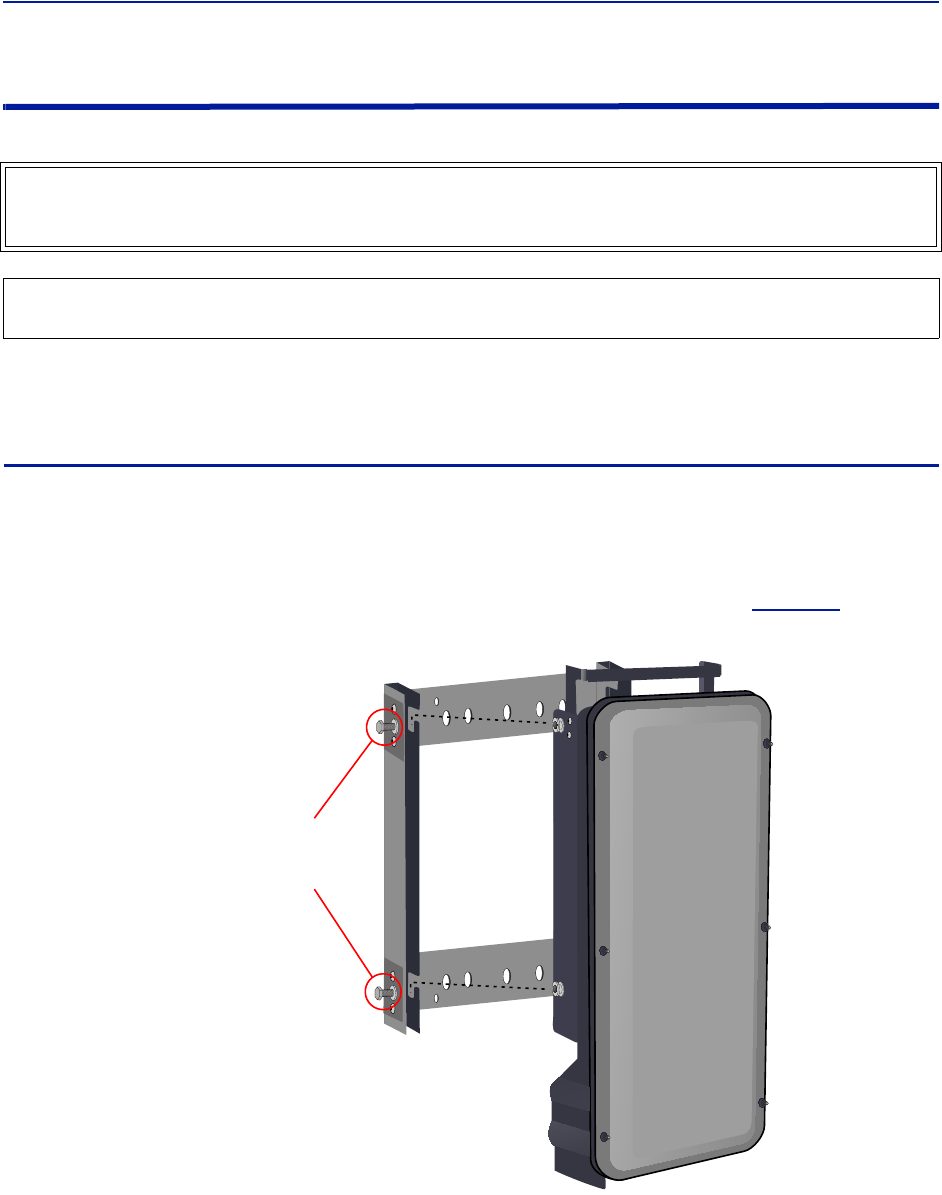
Installationguidelines
50
Installing Remote Units
Theremoteunitsarefactoryconfiguredandshouldnotbeopenedinthefield.
Theremotesmustbemountedinaverticalposition.TherearetworecommendedmethodsforRemoteUnit
installation,wallmountingorpolemounting.Regardlessofthemountingstyleselected,theremotesmustbe
mountedsothatairflowovertheexternalheatsinkisnotobstructed.
Single Remote Unit Wall Mounting
Theremotesareshippedwithstandardwallmountingbrackets.Thesebracketscanbeusedindoorsandoutdoors.
Mountthebracket(p/nDMB301)withouttheremoteattached.
Note: Alwayschecklocalbuildingcodesforpropermountingtechniques!
Oncethebracketisproperlymounted,theremoteeasilyslidesintothemount.See
Figure38
.
Note:
Figure 38
Tighten bolts
(4 places)
After Remote
is Attached
Remote Wall Mount
Oncetheremoteisattachedtothewallmount,theremotemustbeproperlysecuredtothemountby
tighteningboltsateachmountingpoint.
WARNING
TheRemoteUnitsareheavy,usecareandalwaysproperlysupportunitsduringinstallation.Ifallowedtofall
RemoteUnitscancauseinjuryordeath.
CAUTION
EnsurethesurfacesbeingusedtomountRemoteUnitscansafelysupportthefullweightoftheremote.
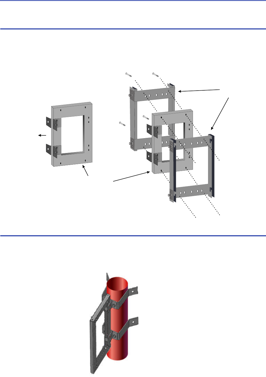
FiberDistributedAntennaSystem(FiberDAS)
51
Double Remote Unit Wall Mounting
BirdTech no lo giesoffersabracketthatallowstwowallmountrackstobemountedbacktoback.Thisreducesthe
amountofwallspacerequiredwhentworemotesarelocatedtogether.Thebracketisstainlesssteelandcanbe
usedindoorsoroutdoors.
Figure 39
Double Wall
Mount Bracket
Mount to Wall
Standard Wall
Mount Brackets
Double Wall Mounting Bracket
Remote Unit Pole Mounting
BirdTech no lo giesalsooffersapolemountingoption.Thepolemountbracketsaredesignedtobeusedwiththe
DoubleRemoteWallMountbracket.
Figure 40 Remote Unit Pole Mounting Option
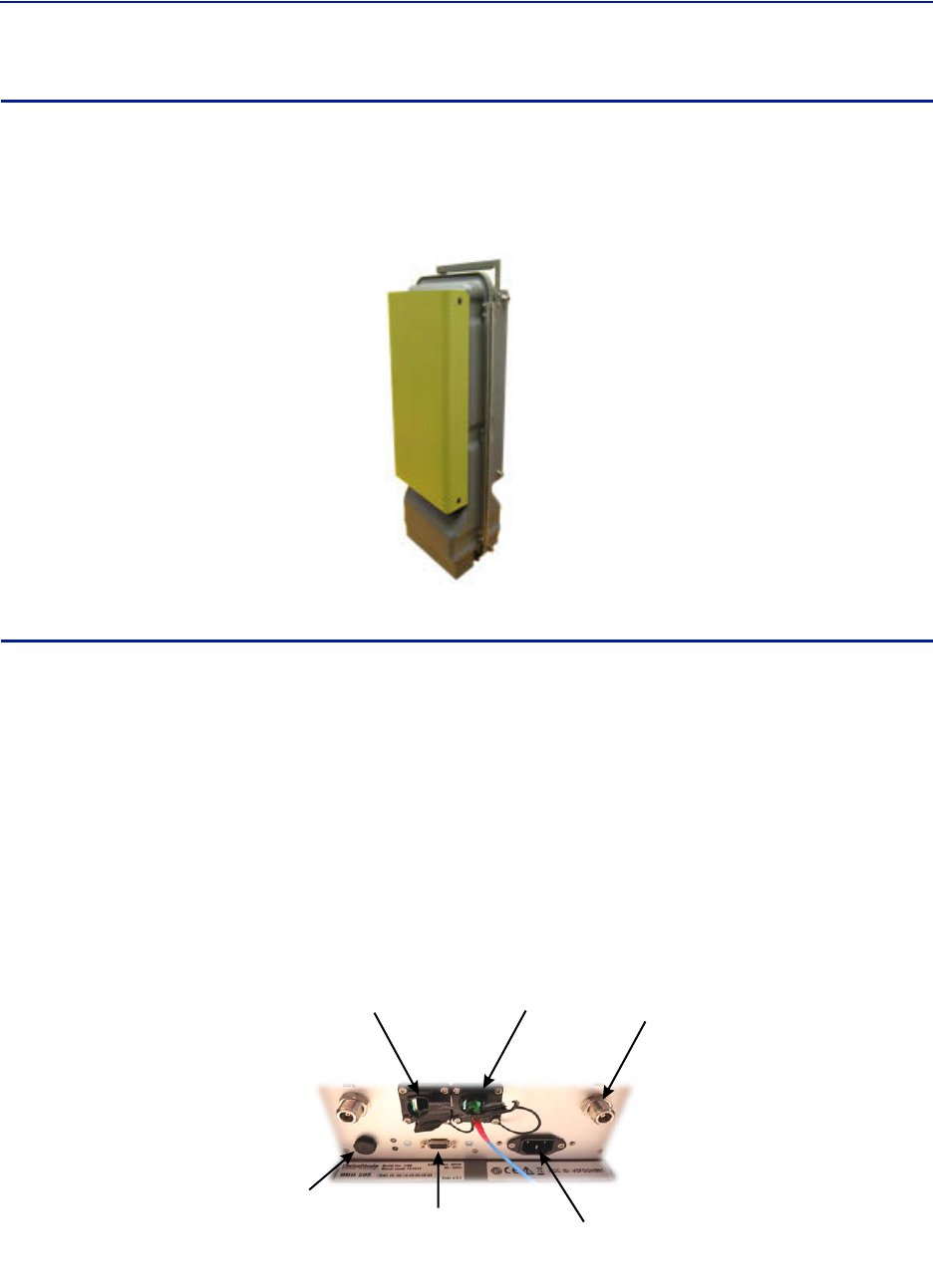
Installationguidelines
52
Solar Shield
Directexposuretosunlightcancausetemperaturesoftheremotetoexceedthe55°C(131°F)rating.Asimple
solutionofferedbyBirdistoattachanoptionalsolarshieldtotheaffectedremotes.Thesolarshields(p/n
DMA301)aresoldseparately.
Figure 41 Remote Unit Solar Shield
Cabling
TherearemanyoptionsfortheBirdremoteswhichcanaffectthenumberofconnectionsonthebottomofeach
remote.Thestandardconnectionsare:
Ethernetport
RFPort(N,miniDINor7/1 6 DIN,SimplexorDuplex)‐Numberofportsvaries
Power(AC)
Externalalarmport
Grounding
FiberOptic
Figure 42 Remote Unit Cabling Connectors
RF Port
Fiber-Optic
Port
Ethernet
Port
External Alarms
Connector
Input Power
Connector
Chassis
Breather
Port
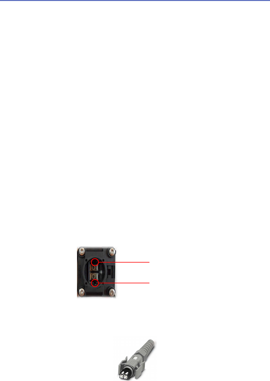
FiberDistributedAntennaSystem(FiberDAS)
53
Ethernet Port
TheRJ45Ethernetportislocatedonthebottompaneloftheremoteunit.ConnectionoftheEthernetportisnot
requiredfornormaloperationoftheDAS.TheportoffersconvenientaccesstothesystemGUIduringinstallation,
commissioningandtroubleshootingoftheDAS.EnsuretheprovidedIP67ratedprotectivecapisreplacedwhenthe
Ethernetportisnotinuse.
IftheEthernetconnectionistobelongtermorpermanent,ensurethattheappropriateEthernetpatchcableis
utilizedtopreventtheingressofmoisterintotheport.
TheEthernetportwillallowsfortwotypesofconnections.
1. RemoteunitisnotconnectedtotheFOIintheMasterUnit
AccesswillbelimitedtotheRemoteUnit.UsermaychangesettingontheRemoteUnit.
StaticIPaddressforlocalaccessishttps://169.254.48.1
Username:"extended"
Password:"admin"
2. RemoteUnitisactivelyconnectedtotheFOIintheMasterUnit
FullaccesstoallGUIfeatureswillbeallowed
AccesswillrequiretheMasterUnitIPaddress:https://172.22.0.1
Username:"extended"
Password:"admin"
Fiber Optic Connection
ThefiberconnectiononthebottomoftheremotehasanIP67ratedprotectivecap.Theprotectivecapmustremain
inplaceuntilthefiberistobeinserted.Thiswillhelppreventforeignparticlesfromdegradingperformanceofthe
fiber.
ThefiberconnectionhasakeyedslotSC/APCconnection.Caremustbetakentoensurethefiberisinstalled
correctly.Itispossibletoforcetheconnectionsothatthefiberisinstalledata180degreerotationcausing
performanceissues.
Note: TheSC/APCkeyisatthetopandbottomontheconnectionontheremote.
Figure 43 Remote Fiber-Optic Connector
Keyed
Connector
ItishighlyrecommendedthatonlytheSCRJfibercablesbeusedwiththeremotes.NotonlydoestheSCRJcable
preventtheingressofmoistureanddustintotothefiberportbutthecablealsoinsuresthefibersarecorrectly
alignedintheconnector.SCRJfibercablesareorderedseparatelyfromBirdTechnologies.
Figure 44 SCRJ Connector