Deltanode Solutions DDH1900 43dBm High Power Remote User Manual Fiber Distributed Antenna System DAS
Deltanode Solutions AB 43dBm High Power Remote Fiber Distributed Antenna System DAS
Contents
- 1. User Manual_Part 1
- 2. User Manual_Part 2
User Manual_Part 2
Installationguidelines
54
AC Power Input
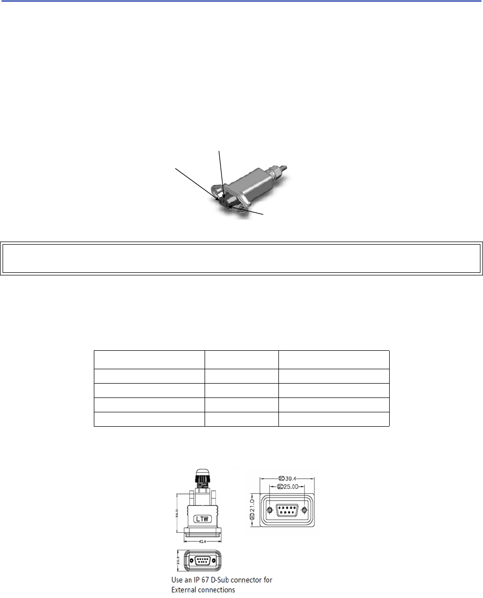
TheBirdremoteonlycomeswithanACinputoption.Thevoltagerangewillsupport120VACor240VAC,50or60Hz.
TheremoteshipswithaweatherproofC13connectorandweatherproofstrainreliefhousing.Theunitdoesnot
shipwithapowercord‐onlythepowerconnector.Theinstallationcontractorwillneedtoprovideapowercableof
atleast14AWG,3conductorcable.
Figure 45 Weatherproof AC Input Connector
Live
Neutral
Ground
External Alarm Connection
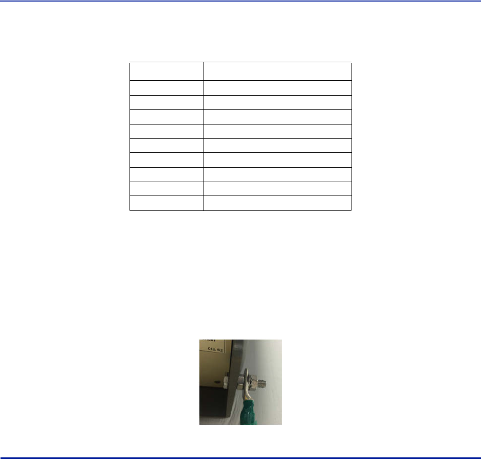
TheexternalalarmportontheBirdremoterequiresanIP67D‐subconnector(notsuppliedbyBird).
Table 63 Alarm Definitions
Alarm Input Level Alarm Text
Error Batteryvoltagelow
Critical LossofmainACpower
Warning Externalalarm3
Error Externalalarm4
Figure 46 External Alarm Connector
WARNING
Electricalinstallationshouldonlybeperformedbyalicensedelectrician.
1 (Pin 9)
2 (Pin 4)
3 (Pin 8)
4 (Pin 3)
FiberDistributedAntennaSystem(FiberDAS)
55
Table 64
Pin Function
AlarmrelayoutputNC
AlarmrelayoutputNO
Alarminput4
Alarminput2
Alarminputground
AlarmrelayoutputNC
AlarmrelayoutputNO
Alarminput3
Alarminput1
External Alarm Connector Pinout
Grounding
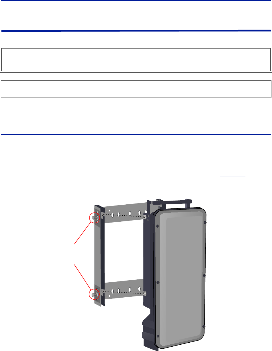
Theremotesarefurnishedwithagroundlugtobeusedifchassisgroundingisrequiredtomeetlocalcodeor
installationrequirements.Theexternalgroundinglugmustbeusedwhentheremoteisinstalledinapplications
whereitissusceptibletolighteningstrikes.
IftheremoteismountedinareaswithhighEMFsuchasnearhighamperagetransformers,turbinesorbroadcast
antennas,properlygroundingthechassiswillprovidereducethelikelihoodinterference.
Figure 47 Remote Ground Connection
Remote Unit Verification
Oncetheremotehasbeenproperlyinstalledandallconnectionsmadetheunitmaybepoweredup.Theunitis
automaticallypowereduponcepowerisappliedtotheACplugonthebottomoftheunit.
Thetypicalpowercycleoftheremoteisapproximately90seconds.TheredandgreenLEDonthebottomofthe
remotewillflashduringthebootcycle.
Oncethebootcycleiscomplete,asolidredLEDindicatesthereisnofiberconnectionorcommunicationto
theDASheadend.
1
2
3
4
5
6
7
8
9
Installationguidelines
56
Installing the DHR Repeater
Therepeatersunitsarefactoryconfiguredandshouldnotbeopenedinthefield.
Theremotesmustbemountedinaverticalposition.TherearetworecommendedmethodsforRemoteUnit
installation,wallmountingorpolemounting.Regardlessofthemountingstyleselected,theremotesmustbe
mountedsothatairflowovertheexternalheatsinkisnotobstructed.
Single Repeater Wall Mounting
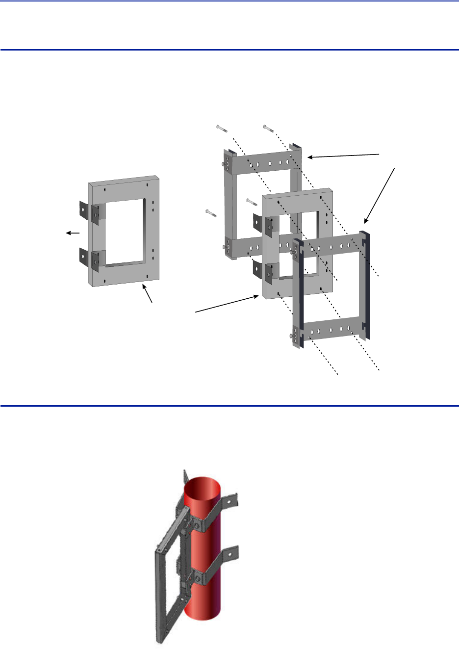
Therepeatersareshippedwithstandardwallmountingbrackets.Thesebracketscanbeusedindoorsandoutdoors.
Mountthebracketwithouttherepeaterattached.
Note: Alwayschecklocalbuildingcodesforpropermountingtechniques.
Oncethebracketisproperlymounted,therepeatereasilyslidesintothemount.See
Figure48
.
Figure 48
Tighten Bolts
(4 places)
after Repeater
is Attached
Repeater Wall Mount
Oncetherepeaterisattachedtothewallmount,therepeatermustbeproperlysecuredtothemountby
tighteningboltsateachmountingpoint.
WARNING
TheRepeatersareheavy,usecareandalwaysproperlysupportunitsduringinstallation.Ifallowedtofalla
Repeatercancauseinjuryordeath.
CAUTION
EnsurethesurfacesbeingusedtomounttheRepeatercansafelysupportthefullweightoftheRepeater.
FiberDistributedAntennaSystem(FiberDAS)
57
Double Repeater Wall Mounting
BirdTechnologiesoffersabracketthatallowstwowallmountrackstobemountedbacktoback.Thisreducesthe
amountofwallspacerequiredwhentworepeatersarelocatedtogether.Thebracketisstainlesssteelandcanbe
usedindoorsoroutdoors.
Figure 49
Double Wall
Mount Bracket
Mount to Wall
Standard Wall
Mount Brackets
Double Wall Mounting Bracket
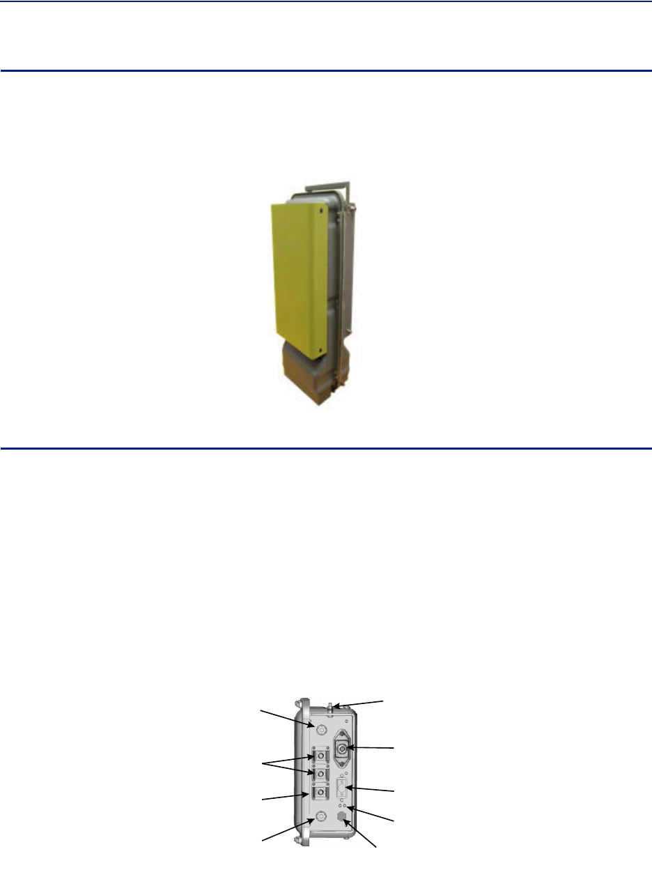
Repeater Pole Mounting
BirdTechnologiesalsooffersapolemountingoption.Thepolemountbracketsaredesignedtobeusedwiththe
DoubleWallMountbracket.
Figure 50 Repeater Pole Mounting Option
Installationguidelines
58
Solar Shield
Directexposuretosunlightcancausetemperaturesoftherepeatertoexceedthe55°C(131°F)rating.Asimple
solutionofferedbyBirdistoattachanoptionalsolarshieldtotheaffectedrepeaters.Thesolarshieldsaresold
separately.
Figure 51 Remote Unit Solar Shield
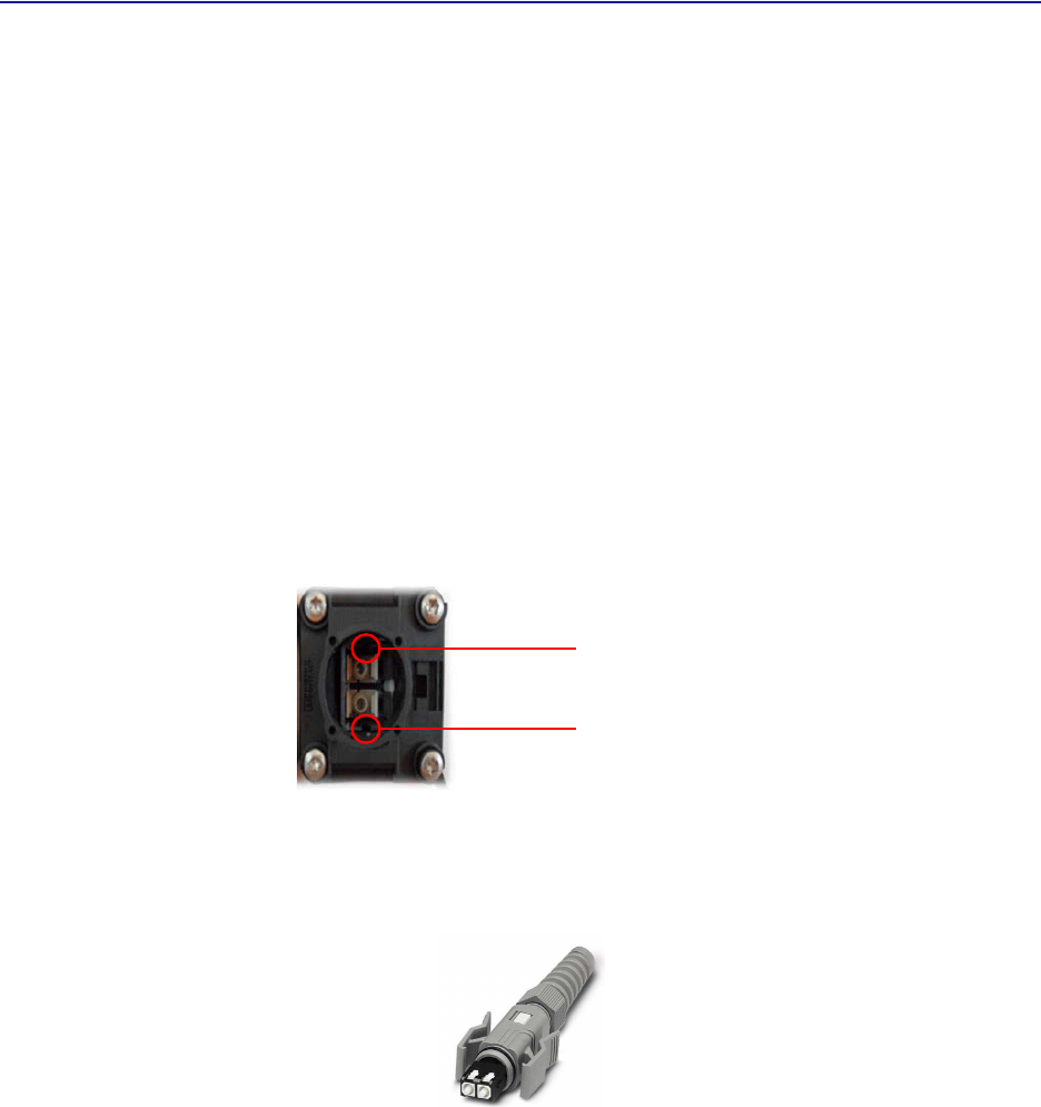
Cabling
TherearemanyoptionsfortheBirdrepeaterswhichcanaffectthenumberofconnectionsonthebottomofeach
repeater.Thestandardconnectionsare:
Ethernetport
RFPorts(N‐Typestandard)
InputPower
Externalalarmport
Grounding
FiberOptic(optional)
Figure 52 Repeater Cabling Connectors
Fiber-Optic
Ports (Optional)
Ethernet
Port
Chassis
Ground
External Alarms
Connector
Input Power
Connector
Chassis
Breather
Port
Service Antenna
Connector
Donor Antenna
Connector
LED Indicators
FiberDistributedAntennaSystem(FiberDAS)
59
Ethernet Port
TheRJ45Ethernetportislocatedonthebottompaneloftherepeaterunit.ConnectionoftheEthernetportisnot
requiredfornormaloperationoftherepeater.TheportoffersconvenientaccesstothesystemGUIduring
installation,commissioningandtroubleshooting.EnsuretheprovidedIP67ratedprotectivecapisreplacedwhen
theEthernetportisnotinuse.
IftheEthernetconnectionistobelongtermorpermanent,ensurethattheappropriateEthernetpatchcableis
utilizedtopreventtheingressofmoisterintotheport.
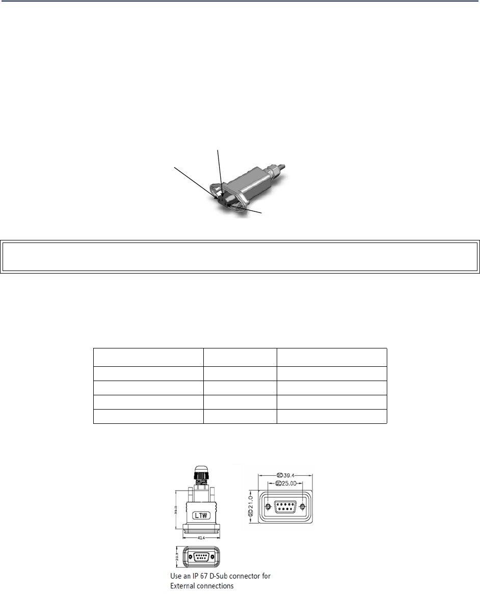
Fiber Optic Connection
Ifthefiberopticoptionisordered,thefiberconnectiononthebottomoftherepeaterhasanIP67ratedprotective
cap.Theprotectivecapmustremaininplaceuntilthefiberistobeinserted.Thiswillhelppreventforeignparticles
fromdegradingperformanceofthefiber.
ThefiberconnectionhasakeyedslotSC/APCconnection.Caremustbetakentoensurethefiberisinstalled
correctly.Itispossibletoforcetheconnectionsothatthefiberisinstalledata180degreerotationcausing
performanceissues.
Note: TheSC/APCkeyisatthetopandbottomontheconnectionontherepeater.
Figure 53 Remote Fiber-Optic Connector
Keyed
Connector
ItishighlyrecommendedthatonlytheSCRJfibercablesbeusedwiththerepeaters.NotonlydoestheSCRJcable
preventtheingressofmoistureanddustintotothefiberportbutthecablealsoinsuresthefibersarecorrectly
alignedintheconnector.SCRJfibercablesareorderedseparatelyfromBirdTechnologies.
Figure 54 SCRJ Connector
Installationguidelines
60
AC Power Input
TheBirdrepeateronlycomeswithanACinputoption.Thevoltagerangewillsupport120VACor240VAC,50or60
Hz.TheremoteshipswithaweatherproofC13connectorandweatherproofstrainreliefhousing.Theunitdoesnot
shipwithapowercord‐onlythepowerconnector.Theinstallationcontractorwillneedtoprovideapowercableof
atleast14AWG,3conductorcable.
Figure 55 Weatherproof AC Input Connector
Live
Neutral
Ground
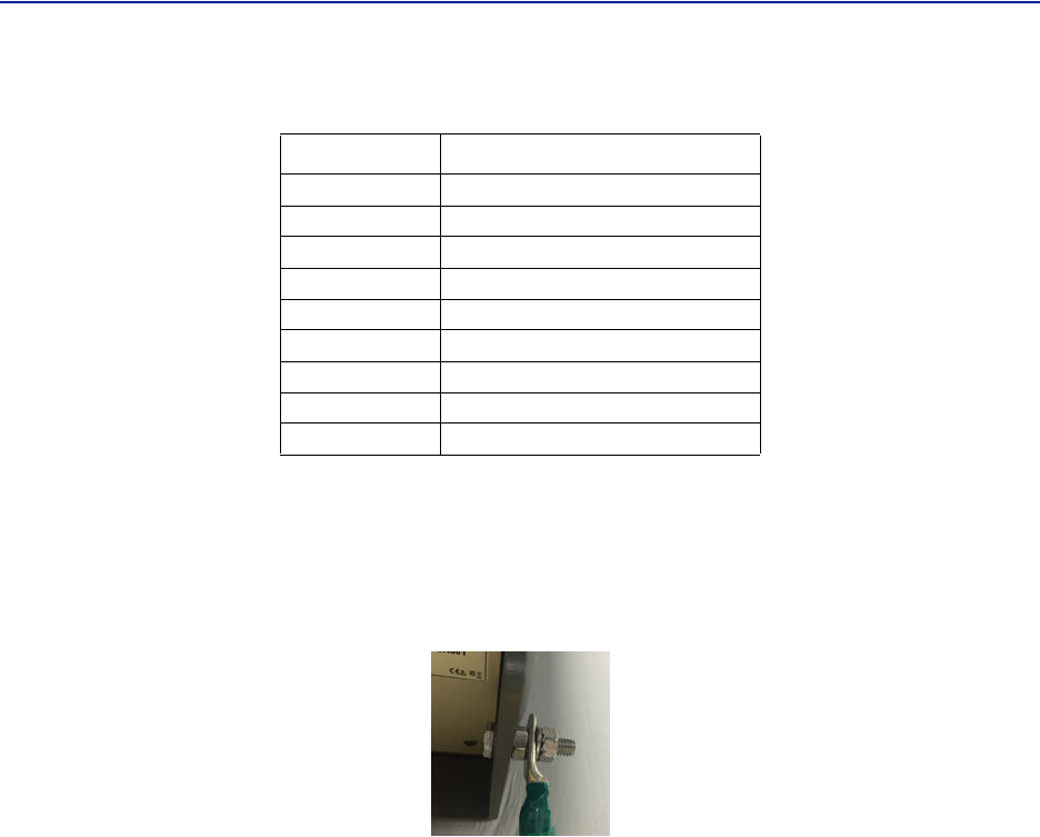
External Alarm Connection
TheexternalalarmportontherepeaterrequiresanIP67D‐subconnector(notsuppliedbyBird).
Table 65 Alarm Definitions
Alarm Input Level Alarm Text
Error Batteryvoltagelow
Critical LossofmainACpower
Warning Externalalarm3
Error Externalalarm4
Figure 56 External Alarm Connector
WARNING
Electricalinstallationshouldonlybeperformedbyalicensedelectrician.
1 (Pin 9)
2 (Pin 4)
3 (Pin 8)
4 (Pin 3)
FiberDistributedAntennaSystem(FiberDAS)
61
Table 66
Pin Function
AlarmrelayoutputNC
AlarmrelayoutputNO
Alarminput4
Alarminput2
Alarminputground
AlarmrelayoutputNC
AlarmrelayoutputNO
Alarminput3
Alarminput1
External Alarm Connector Pinout
Grounding
Therepeatersarefurnishedwithagroundlugtobeusedifchassisgroundingisrequiredtomeetlocalcodeor
installationrequirements.
Figure 57 Remote Ground Connection
1
2
3
4
5
6
7
8
9
62
Chapter 4 DAS Software Configuration
ThissectionisfocusedontheGUIinterfaceandinitialsoftwaresettingoftheDAS.Nospecialsoftwareisrequireto
accesstheBirdDAS.AccessisprovidedviamostwebbrowserssuchasMozillaFirefoxorGoogleChrome.
TheBGWshouldbepoweredupandallowedabout5minutestofullybootpriortoapplyingpowertotheMaster
Unit.TheBGWwillassignIPaddressestotheMasterUnitcomponents.IftheMasterUnitispowereduppriortothe
BGWthenitcouldtakeupto30minutesfortheMasterUnitcomponentstogetassignedanIPaddress.MasterUnit
cardswillshowaquickflashofthegreenLEDwhenanIPaddresshasbeenassigned.
SpecialNote:Thefollowingisbasedonversion3.5software.
Ethernet Connection
1. ConnectalaptoptoanyopenportontheHeadendEthernetswitch.
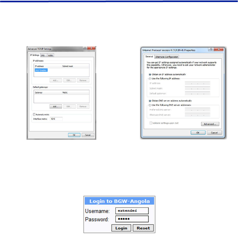
2. EnsurethelaptopnetworksettingshaveDHCPenabledandthe“ObtainanIPaddressautomatically”radio
buttonchecked.
Figure 58 Windows TCP/IP Settings
3. UsinganInternetbrowsergotohttps://172.22.0.1toaccesstheBGW.Asuccessfulentrywillshowaccesstothe
loginpage.
4. LogintotheBGW.
Username:"extended"
Password:"admin"
Figure 59 BGW Login page
FiberDistributedAntennaSystem(FiberDAS)
63
BGW Configuration
BGW Naming
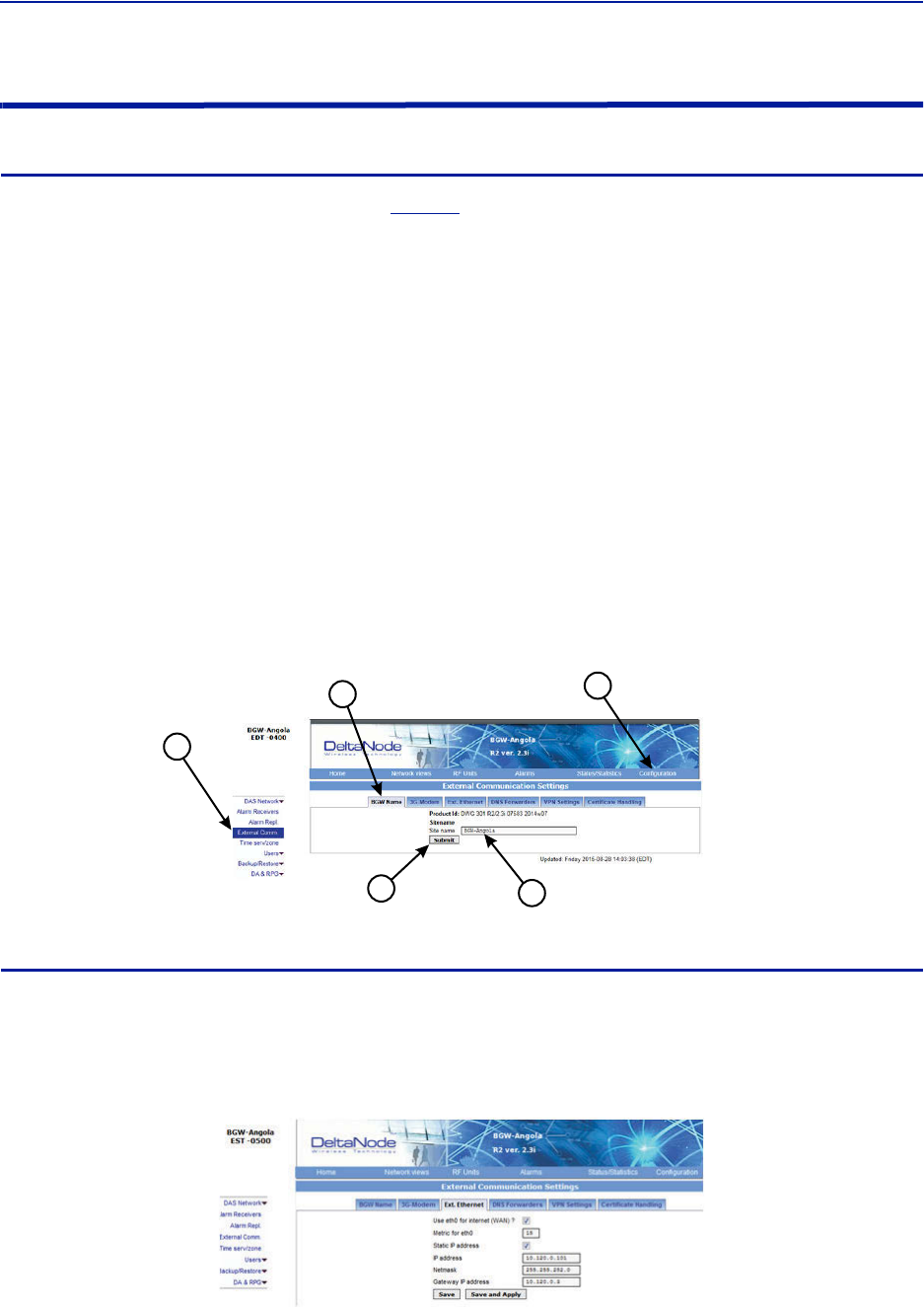
1. SelectConfigurationintoprightcorner.See
Figure60
.
2. SelectExternalComminleftmenu.
3. SelectBGWNametabintopmenu.
4. Entersitename:
a. Youmayuseanycombinationofalphanumericcharactersandthespecialcharacterofdash"‐".Donot
useanyotherspecialcharactersorspace.
0through9
athroughz
AthroughZ
‐
Limitof56characters
b. UseasitenamethatisdescriptiveenoughtodistinguishtheBGWfromothersites.Genericnamesmay
delaytroubleshootingefforts.
5. ClickSubmit.
Note: Afterthenewhostnameisentered,theunitmustberestarted.Thisistheonlychangethat
requiresarestart.SelectthephysicalrestartbuttonontheleftsideoftheBGW.
Figure 60 BGW Site Name
1
54
3
2
EXT Ethernet
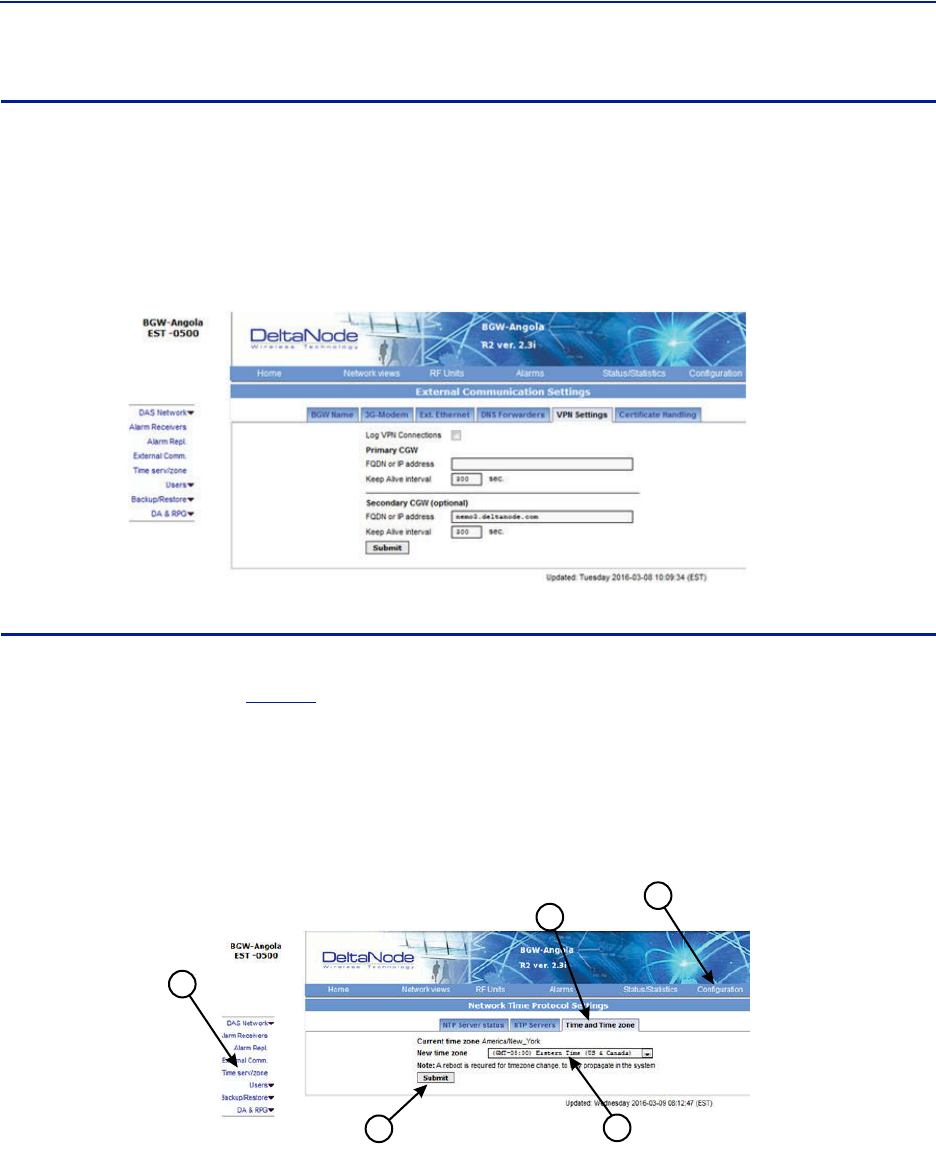
InorderfortheBGWtobeabletocommunicateoutward,theExtEthernetconnectionhastobeprogrammed.
ConsultwithyourInternetserviceproviderorITdepartmentfortheIPaddress,NetmaskandGatewayIPaddress
settings.
Figure 61 BGW External Communications
DASSoftwareConfiguration
64
VPN Settings
Onoccasions,theBGWwillbesetupbehindafirewall.TobeabletoaccesstheBGWfromexternallocationsthe
PrimaryBGWsettingswillneedtobeconfiguredtoallowaccess.ConsultwithyourITdepartmentforthese
parameters.
BirdTechnologiesoffersmonitoringservices.Whentheseservicesarecontracted,entertheBirdparametersinthe
SecondaryBGWsettingssothatsystemalarmsarecorrectlyforwardedtotheBirdNOC.
Figure 62 BGW VPN Settings
Time Zone
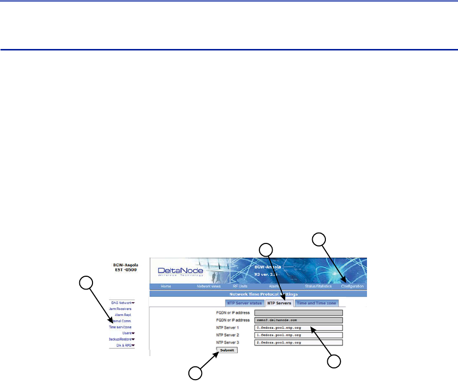
ToensurethatalarmsarecorrectlylabeledwiththelocaltimethetimezonefortheBGWwillneedtobeset.
1. SelectConfiguration.See
Figure63
.
2. ClickTimeserv/zone.
3. SelecttheTimeandTimezoneTab.
4. Selectthelocaltimezonefromthedrop‐downmenu.
5. ClickSubmit.
Figure 63
1
54
3
2
BGW Time Zone Settings
FiberDistributedAntennaSystem(FiberDAS)
65
NTP Servers
NTPserversprovideaccurateclocksfortheBGW.Utilizingmultiplesourcespreventsclockissuesasaresultofone
serverbecomingcorruptordroppingoutofcontact.TheBGWiscompatiblewithNTPversion4servers.TheNTP
settingsintheimagebelowarethedefaultforRedhatservers.
1. SelectConfiguration.
2. ClickTimeserv/zone.
3. SelecttheNTPServersTab.
4. EntertheNTPServerinformation.TheFQDNsettingsarereservedfordeploymentsutilizingtheCGW.
5. ClickSubmit.
IfnoInternetaccessisavailable,theBGWwillcreateitsownclocktogivethesub‐nodesofthesystemavalidNTP
service.
Figure 64
1
5
4
3
2
NTP Server Settings
DASSoftwareConfiguration
66
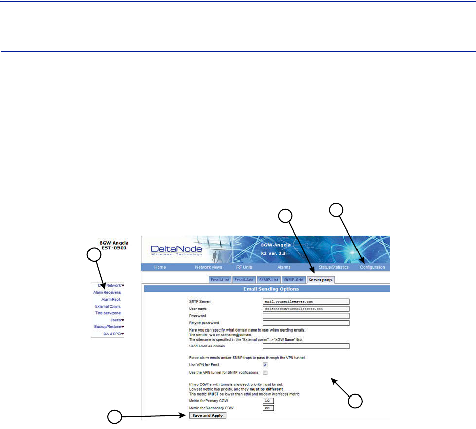
Email Server
TheBGWiscapableofemailingalarmsdirectlytoselectemailaddresses.Accessthesetupfunctionvia
Configuration,AlarmReceiversandServerProp.
ConsultwithyourITdepartmentforconfigurationsettings.
1. SelectConfiguration.
2. ClickAlarmReceivers.
3. SelecttheServerProp.Tab.
4. EntertheEmailServerinformation.ConsultwithyourITdepartmentforconfigurationsettings.
5. ClickSaveandApply.
Figure 65
1
5
4
3
2
Email Server Settings
FiberDistributedAntennaSystem(FiberDAS)
67
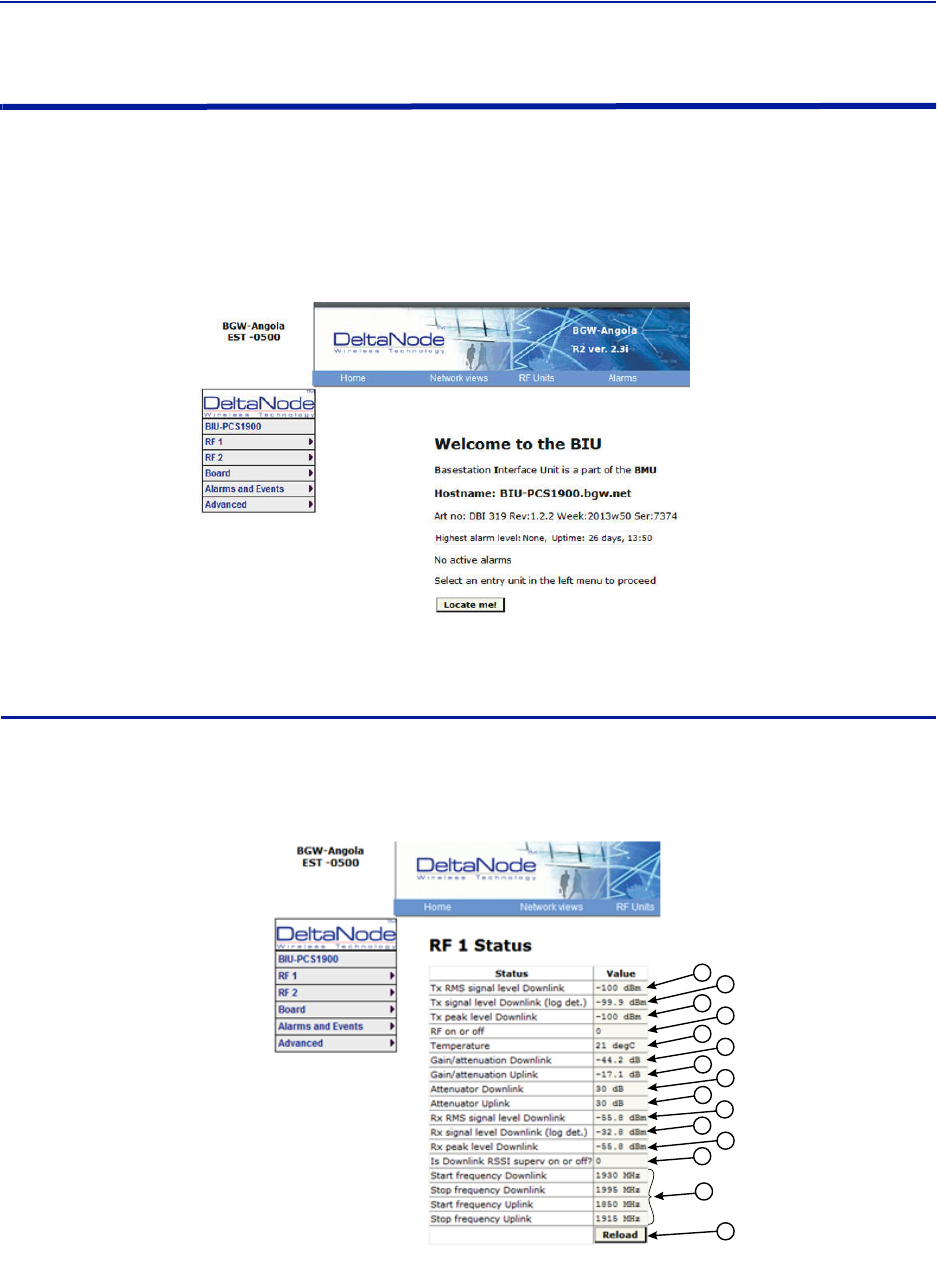
BIU Configuration
TheinitialscreenfortheBIUprovidesbasicinformationsuchasname,serialnumber,partnumberandactive
alarms.TheLocateme!buttoncausesanLEDtoflashontheunitsothatthemodulecanbeidentifiedinthechassis.
Intheleftmenu,noticetheRF1andRF2.TheBIUhastwoRFpathsorstripsthatarecorrelatedtothetwoRFinputs
ontheBIUcard.EachRFpathhasindependentsettingsthatcanbeaccessedviatheappropriateselection.
Figure 66 BIU Welcome Screen
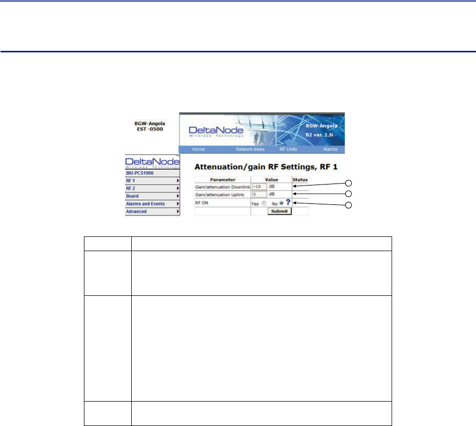
BIU RF1 Status
ThispageshowsthecurrentstatusandconfigurationoftheBIU.
Figure 67
12
3
4
5
6
7
8
9
10
11
12
13
14
15
BIU RF1 Status

DASSoftwareConfiguration
68
Item Description
1DownlinkRMSvalueleavingtheBIUcardtotheICU/FOI.Goodfor
measuringGSMandUMTSlevels.
2DownlinklogdetectorsignalleavingtheBIUcardtotheICU/FOI.
3PeakdownlinkRFvalueexitingtheBIUcardontheselectpath.
4
0=RFissettoOff(attenuationissettomaximum).
1=RFissettoOn.
Note:ThisisonlyinreferencetooneofthetwoBIURFpaths/strips.
5TemperatureoftheBIUcard.
6
ThismeasurementistheactuallossofthedownlinkRFsignalintheBIU
takingintoaccountraworinherentlossofthecardplustheadjustable
attenuator.
7
ThismeasurementistheactualgainorlossontheuplinkRFsignalintheBIU
takingintoaccountraworinherentgainofthecardplustheuplink
adjustableattenuator.
8
AdjustabledownlinkattenuatorsettingfortheselectedRFpath.
Note:Ifthedownlinkpathisturnedoff(see#4)theattenuatorvalueis
automaticallysettomaximumattenuation.WhenRFisturnedon,the
settingoftheadjustableattenuatorwillbeshown.
9
AdjustableuplinkattenuatorsettingfortheselectedRFpath.
Note:Ifthedownlinkpathisturnedoff(see#4)theattenuatorvalueis
automaticallysettomaximumattenuation.WhenRFisturnedon,the
settingoftheadjustableattenuatorwillbeshown.
10
CalculateddownlinkRMSvalueenteringtheBIUcardfromtheBTS.
Note:ThisisthedownlinkintotheBIUcardandnotanuplinkvalue.
11
CalculateddownlinkvalueenteringtheBIUcardfromtheBTS.
Note:ThisisthedownlinkintotheBIUcardandnotanuplinkvalue.
12
PeakdownlinkRFvalueenteringtheBIUcardontheselectpath.
Note:ThisisthedownlinkintotheBIUcardandnotanuplinkvalue.
13 0=DownlinkalarmissettoOff.
1=UplinkalarmissettoOn.
14 BandwidthoftheBIUcard
15 PressingReloadwillrefreshthepage
FiberDistributedAntennaSystem(FiberDAS)
69
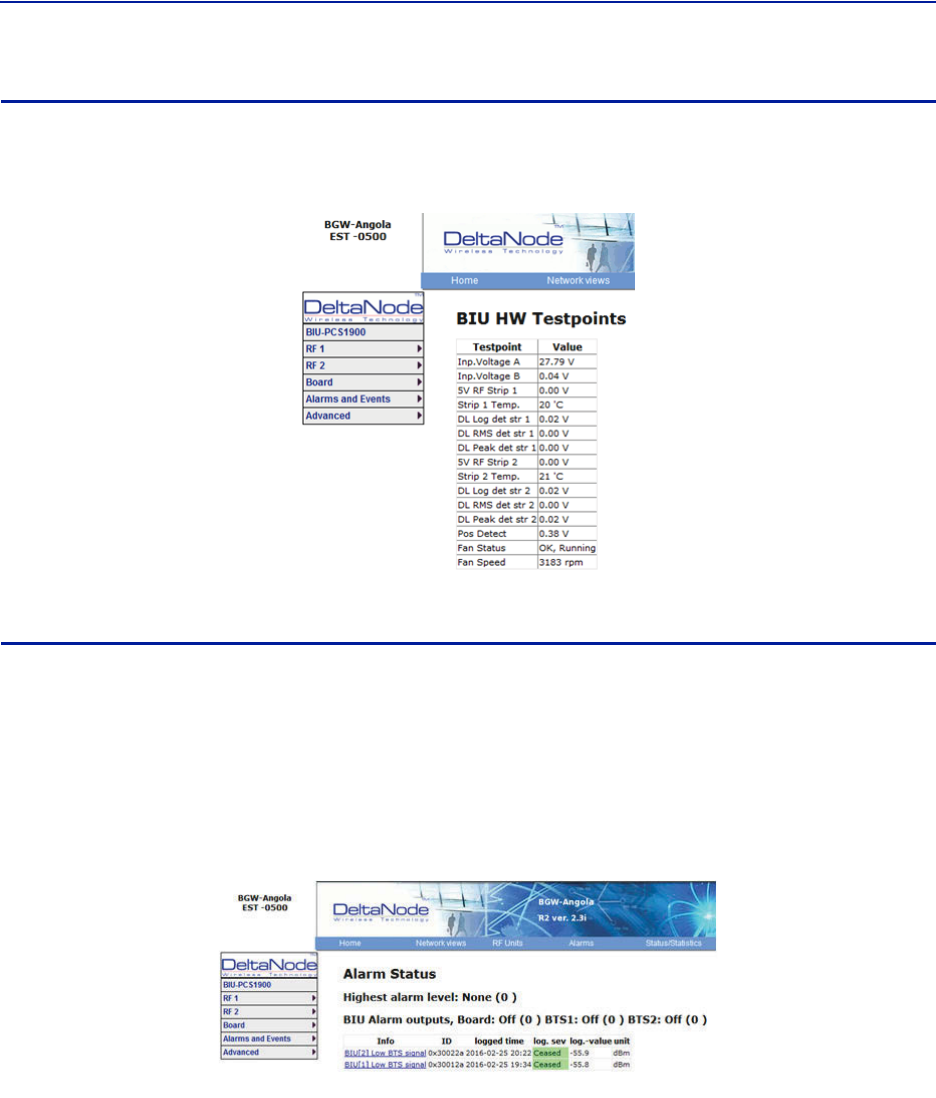
BIU RF1 Settings
ThispagewillallowtheusertochangetheattenuatorvaluesintheBIUforthepathselected.
Figure 68 BIU RF1 Settings
1
2
3
Item Description
1
Attenuatorsettingforthedownlinkpath.Enteravaluefrom‐14to‐44
(rangevariesdependingoffrequencyband).
Note:ClickSubmitafterenteringvalue.
2
Attenuator/Gainsettingfortheuplinkpath.
Enteravaluefrom‐17to12(rangevariesdependingoffrequencyband).
NotethattheBIUhasrawgainintheuplinkpathoncertainBIUtypes(gain
canbedeterminedbypositivevalueinthesettingrange.
Aselectionof12indicatesfullgainof12dBintheBIU.
Aselectionof9willdecreasetheBIUuplinkoutputby3dB.
Aselectionof0willdecreasetheBIUuplinkoutputby12dB.
Aselectionof‐17willdecreasetheBIUuplinkoutputby29dB.
Note:ClickSubmitafterenteringvalue.
3ThisselectionturnstheuplinkpathOnorOff(maximumattenuation
setting).
DASSoftwareConfiguration
70
BIU Hardware Test Points
Thispageshowsvarioustestpointmeasurementsusedforstatusandtroubleshootingpurposes.
Figure 69 BIU Hardware Test Points
BIU Alarm List
Thispageshowallcurrentandpastalarms.
Greenindicatesthatthealarmhascleared.
Yellowindicatesawarningalarm.
Redindicatesaserviceaffectingalarm.
Figure 70 BIU Alarm List
FiberDistributedAntennaSystem(FiberDAS)
71
BIU Change History
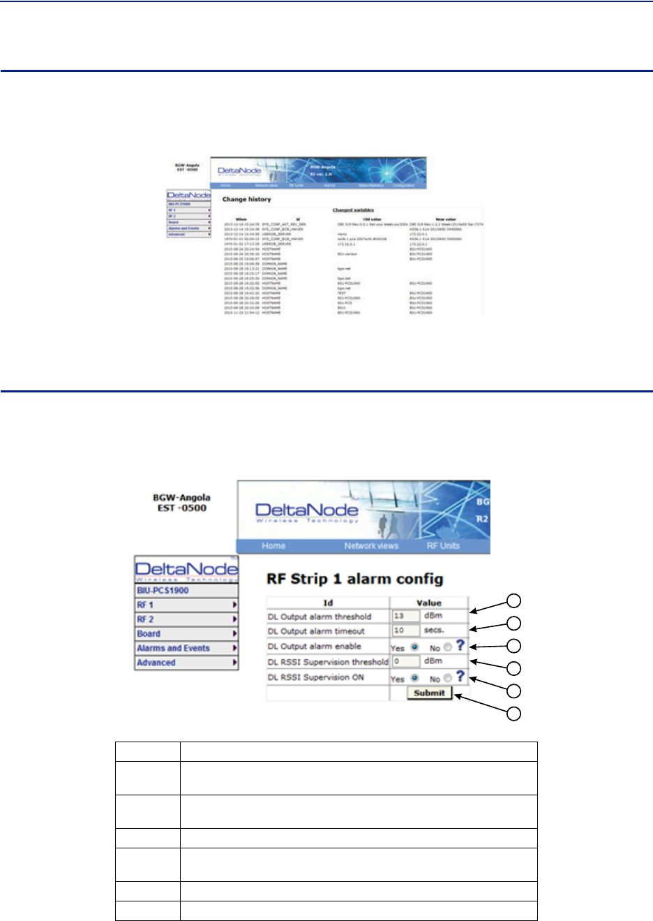
Thispageshowsahistoryofallsettingchanges.
Figure 71 BIU Change History
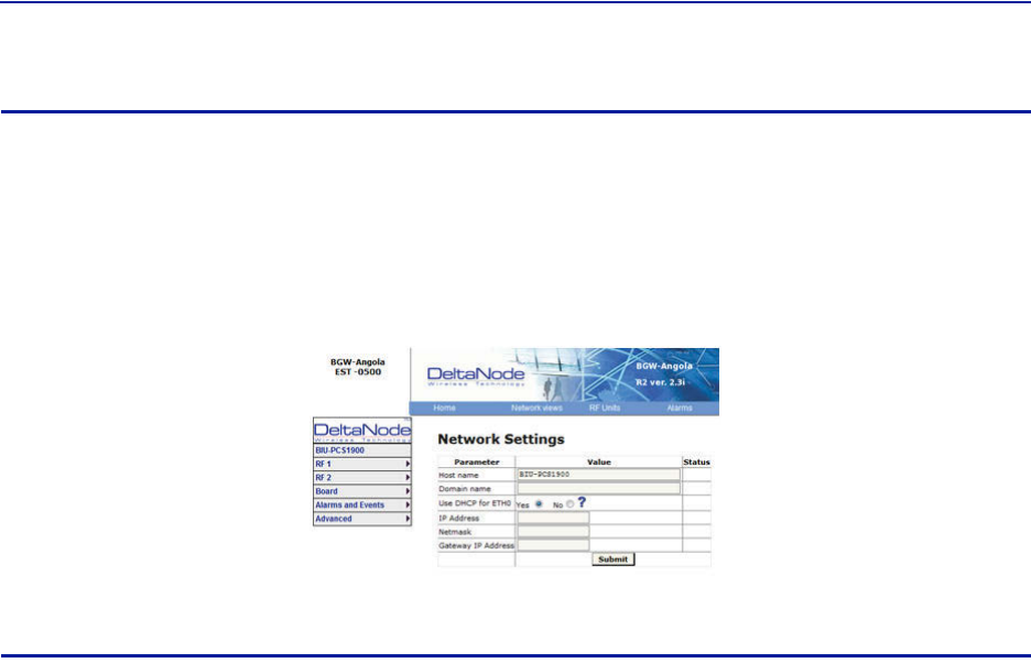
BIU Alarm configuration RF1
ThispageallowsforcertainalarmthresholdsoftheBIUtobechanged.
Figure 72 BIU Alarm configuration
1
2
3
4
5
6
Item Description
1SetthevalueindBmthattheBIUdownlinkoutputhastoexceedinorderto
createanalarm
2SetthevalueinsecondsfortheamountoftimethattheBIUdownlink
outputhastobeabovethethresholdlevelinordertocreateanalarm.
3 EnablesordisablesBIUthreshold/highpoweralarm.
4SetthevalueindBmthattheBIUdownlinkoutputhastodropbelowin
ordertocreateanalarm.
5 EnablesordisablesBIUsupervision/lowlevelalarm.
6ClickSubmitafterenteringvalue(s).
DASSoftwareConfiguration
72
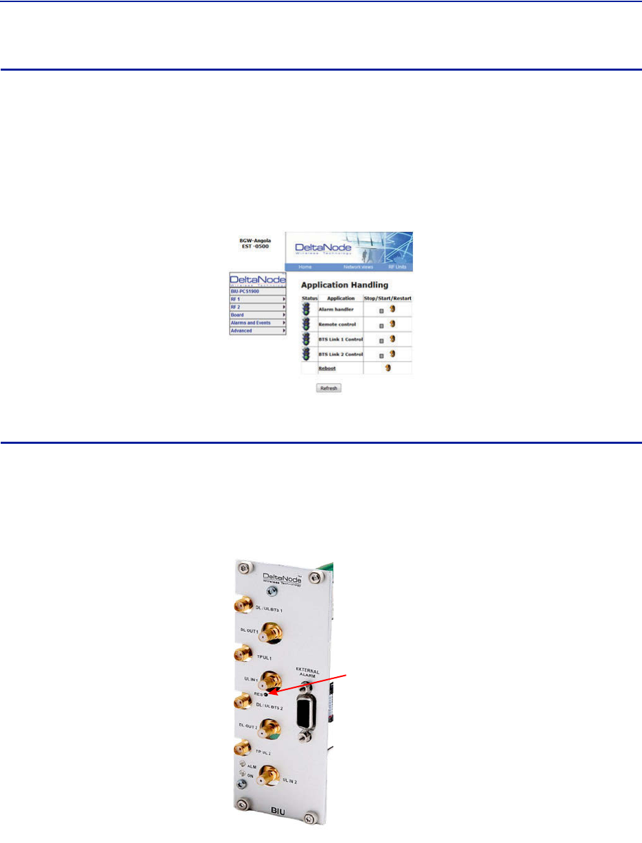
BIU Advanced Network Setup
Thispageallowsformanualoverrideofnetworksettings.
DefaultconfigurationsshouldbeusedwithDHCPsettoYes.
Note: ChangingDHCPto“No”cancauselossofcommunicationstotheBIUandshouldonlybeusedin
veryspecificsituations.
Figure 73 BIU Network Setup
BIU Advanced Menus
ThesemenusprovideinformationonlystatusandsettingsoftheBIUthataretypicallyusedbythemanufacturer.
BIU>Advanced>HWconfig
BIU>Advanced>AD‐valuesRF1
BIU>Advanced>AD‐valuesRF2
BIU>Advanced>ADCraw
BIU>Advanced>Softwarestatus
BIU>Advanced>Processstatus
BIU>Advanced>Systemstatus
FiberDistributedAntennaSystem(FiberDAS)
73
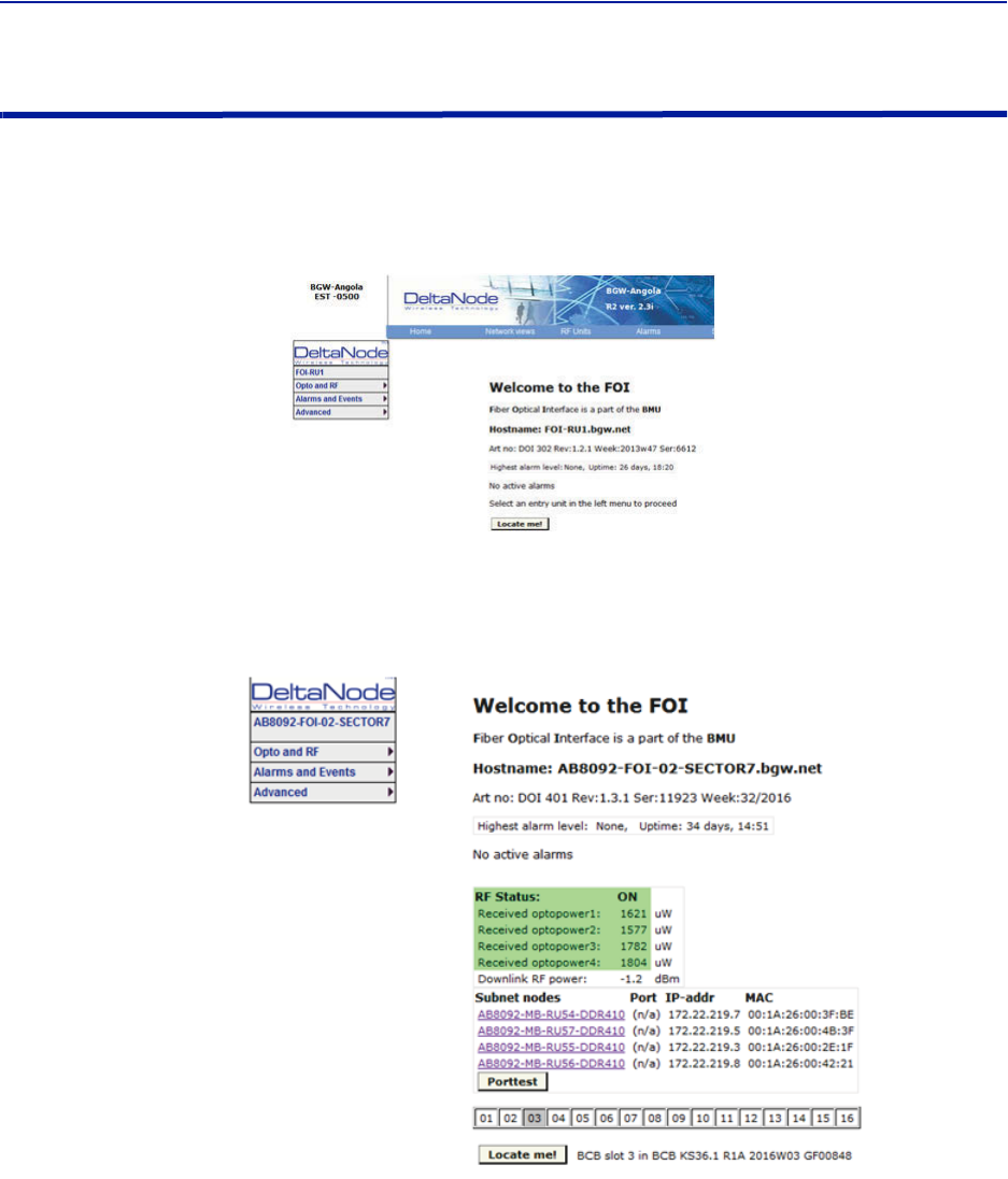
BIU Application Handling
Theapplicationhandlingpageallowsforstoppingsoftwarefunctionsandrebootingsoftwareprograms.
AlarmHandler:SelectingReboot(circularicon)willclearallthealarmsinthehistoryforthecardselected.Thisis
helpfulafterturningasystemupandwantingtoclearalarmlogcreatedduringtheinstallationandturnup.
Note: OnlytheRebootcommandshouldbeusedbythetechnician.Allotherfunctionsshouldonlybe
usedundersupervisionofBirdengineeringastheymaycausedatacorruptionifnotinitiatedproperly.
TheradiobuttonwillstopaprocessandcanhavenegativeaffectsonthefunctionoftheDAS.
Figure 74 BIU Application Handling
BIU Reset to Factory Default
ToresettheBIUtofactorydefault,carefullypressthe“Reset”button[locatedbelowtheULIn1QMAconnector]for
10seconds.ThisishelpfulwhenacardfailstoappearintheConfigurationmenu.
Figure 75 BIU Reset
Reset
DASSoftwareConfiguration
74
FOI Configuration
TheinitialscreenfortheFOIprovidesbasicinformationsuchasname,serialnumber,partnumberandactive
alarms.TheLocateme!buttoncausesanLEDtoflashontheunitsothatthemodulecanbeidentifiedinthechassis.
Figure 76 FOI Welcome Screen
Figure 77 FOI Welcome Screen SW Version 3.9, DOI401
FiberDistributedAntennaSystem(FiberDAS)
75
FOI Opto Status
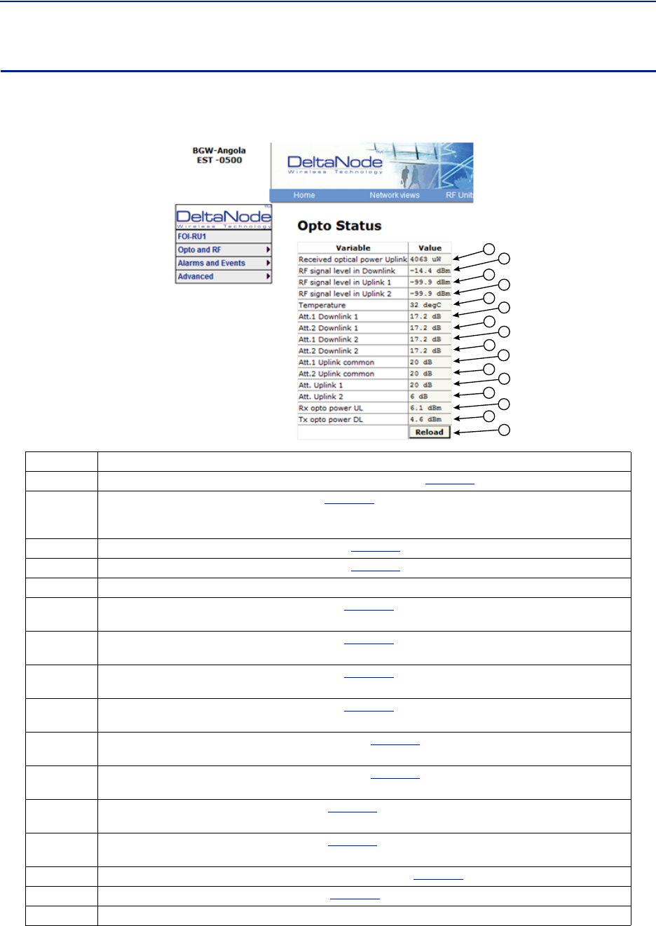
ThispagewillshowthecurrentstatusandconfigurationoftheFOI.
Figure 78 FOI Opto Status
1
2
3
4
5
6
7
8
9
10
11
12
13
14
16
15
Item Description
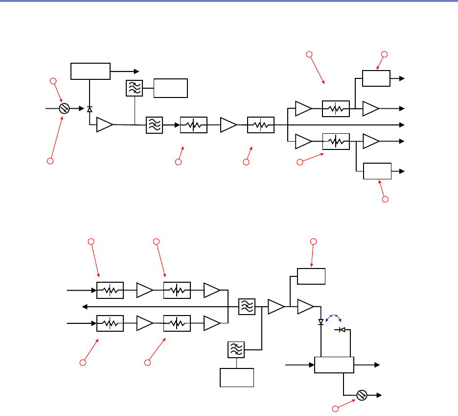
1Fiberopticreceivedopticalpowerfromtheremoteunit.Seeitem1in
Figure79
formeasurementlocation.
2
RFdownlinkpowertotheremote.Seeitem2in
Figure80
forlocationontheFOIcircuitry.NotethatwithnoRF
powerintotheBIUtheFORwillstillshowsignalinthedownlink.Thisisthesub‐carrierthatistypically10dBbelow
theanticipatedRFlevel.
3RFpath1inputpowerfromtheremote.Seeitem3in
Figure79
forlocationontheFOIcircuitry.
4RFpath2inputpowerformtheremote.Seeitem4in
Figure79
forlocationontheFOIcircuitry.
5TemperatureoftheFOIcard
6Downlinkpath1attenuator#1setting.Seeitem6in
Figure80
forlocationontheFOIcircuitry.Valuemaybe
slightlydifferentthanthevalueinSettingsduetochangesintemperaturecompensation.
7Downlinkpath1attenuator#2setting.Seeitem7in
Figure80
forlocationontheFOIcircuitry.Valuemaybe
slightlydifferentthanthevalueinSettingsduetochangesintemperaturecompensation.
8Downlinkpath2attenuator#1setting.Seeitem8in
Figure80
forlocationontheFOIcircuitry.Valuemaybe
slightlydifferentthanthevalueinSettingsduetochangesintemperaturecompensation.
9Downlinkpath2attenuator#2setting.Seeitem9in
Figure80
forlocationontheFOIcircuitry.Valuemaybe
slightlydifferentthanthevalueinSettingsduetochangesintemperaturecompensation.
10 Uplinkcommonpathattenuator#1setting.Seeitem10in
Figure79
forlocationontheFOIcircuitry.Valuemay
beslightlydifferentthanthevalueinSettingsduetochangesintemperaturecompensation.
11 Uplinkcommonpathattenuator#2setting.Seeitem11in
Figure79
forlocationontheFOIcircuitry.Valuemay
beslightlydifferentthanthevalueinSettingsduetochangesintemperaturecompensation.
12 Uplinkpath#1attenuatorsetting.Seeitem12in
Figure79
forlocationontheFOIcircuitry.Valuemaybeslightly
differentthanthevalueinSettingsduetochangesintemperaturecompensation.
13 Uplinkpath#2attenuatorsetting.Seeitem13in
Figure79
forlocationontheFOIcircuitry.Valuemaybeslightly
differentthanthevalueinSettingsduetochangesintemperaturecompensation.
14 Calculateduplinkopticalinputfromtheremoteunit.Seeitem14in
Figure79
forlocationontheFOIcircuitry.
15 Calculateddownlinkopticaloutput.Seeitem9in
Figure80
forlocationontheFOIcircuitry.
16 PressingReloadwillrefreshthepage
DASSoftwareConfiguration
76
Figure 79 FOI Uplink Measurement Locations
DETECTOR
DETECTOR
CURRENT
SENSOR
ETHERNET
MODEM
OPTO IN
RX-LVL
UL OUT 2
UL OUT 1
TP UL
Attenuator
Common 1
PHOTO
DETECTOR
Attenuator
Common 2
Attenuator
Uplink 1
Attenuator
Uplink 2
STEP ATT STEP ATT
STEP ATT
STEP ATT
RX POWER 1
RX POWER 2
1
3
4
10 11
12
13
14
Figure 80 FOI Downlink Measurement Locations
DETECTOR
LASER
DRIVER
ETHERNET
MODEM
OPTO OUT
DETECTOR
MONITOR
TX-LVL
DL IN 1
DL IN 2
TP DL
STEP ATT
Attenuator 1
Downlink 1
Attenuator 1
Downlink 2
Attenuator 2
Downlink 1
Attenuator 2
Downlink 2
STEP ATT
STEP ATT
STEP ATT
2
67
8 9
15
FiberDistributedAntennaSystem(FiberDAS)
77
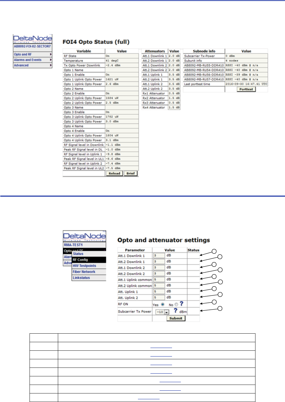
Figure 81 FOI Opto Status DOI401
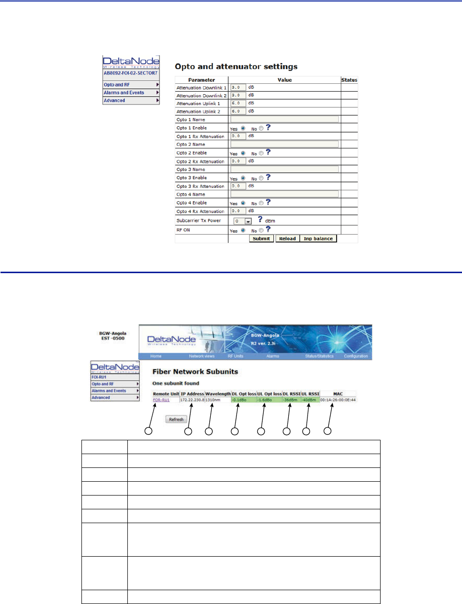
FOI Opto and Attenuator Settings
ThispagewillallowchangestobemadetotheFOIvalues
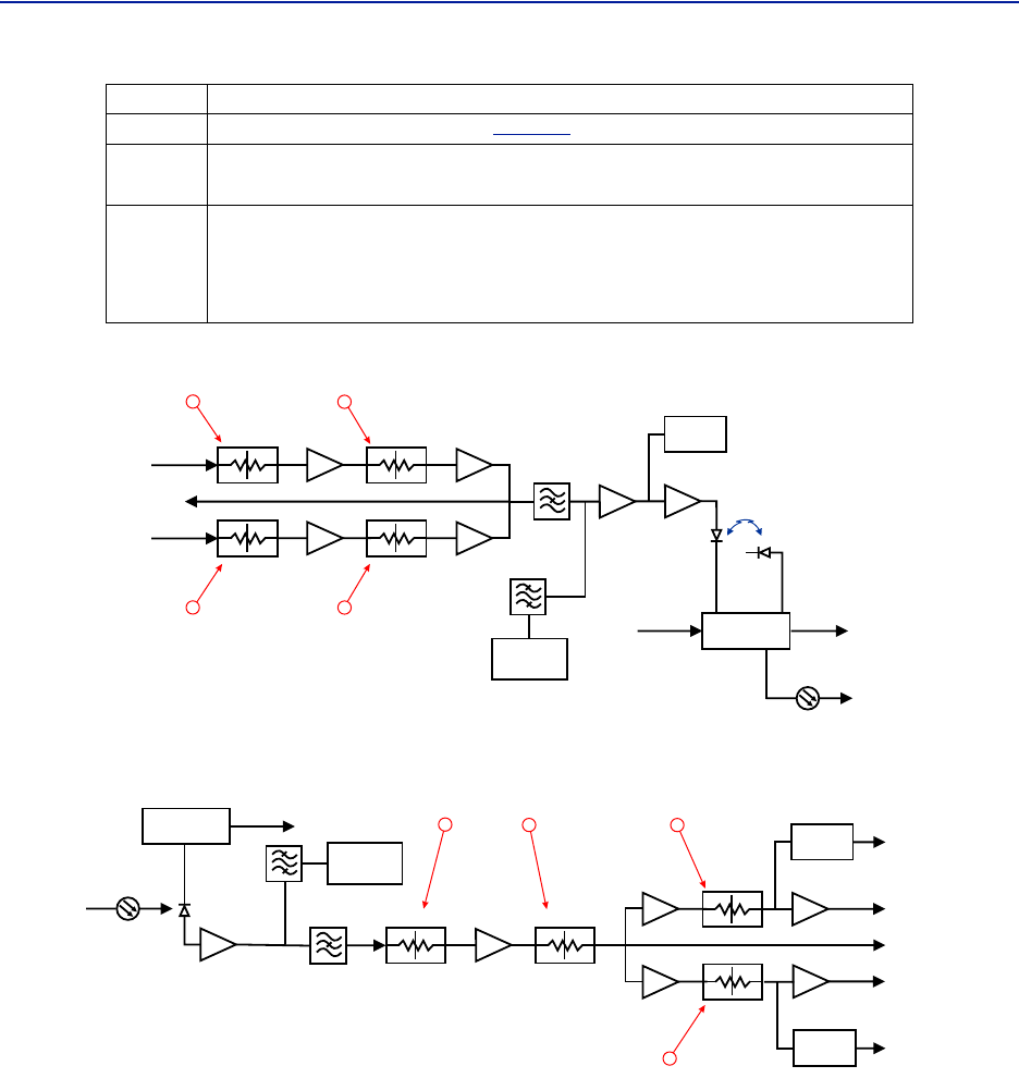
Figure 82
1
2
3
4
5
6
7
8
9
10
FOI Opto and Attenuator Settings
Item Description
1Downlinkpath1attenuator#1.Seeitem1in
Figure83
formeasurementlocation.
2Downlinkpath1attenuator#2.Seeitem2in
Figure83
forlocationontheFOIcircuitry.
3Downlinkpath2attenuator#1.Seeitem3in
Figure83
forlocationontheFOIcircuitry.
4Downlinkpath2attenuator#2.Seeitem4in
Figure83
forlocationontheFOIcircuitry.
5Uplinkcommonpathattenuator#1.Seeitem5in
Figure84
forlocationontheFOIcircuitry.
6Uplinkcommonpathattenuator#2.Seeitem6in
Figure84
forlocationontheFOIcircuitry.
7Uplinkpath1attenuator.Seeitem7in
Figure84
forlocationontheFOIcircuitry.
DASSoftwareConfiguration
78
Figure 83 Downlink Opto and Attenuator Settings
DETECTOR
LASER
DRIVER
ETHERNET
MODEM
OPTO OUT
DETECTOR
MONITOR
TX-LVL
DL IN 1
DL IN 2
TP DL
STEP ATT
Attenuator 1
Downlink 1
Attenuator 1
Downlink 2
Attenuator 2
Downlink 1
Attenuator 2
Downlink 2
STEP ATT
STEP ATT
STEP ATT
12
34
Figure 84 Uplink Opto and Attenuator Settings
DETECTOR
DETECTOR
CURRENT
SENSOR
ETHERNET
MODEM
OPTO IN
RX-LVL
UL OUT 2
UL OUT 1
TP UL
Attenuator
Common 1
PHOTO
DETECTOR
Attenuator
Common 2
Attenuator
Uplink 1
Attenuator
Uplink 2
STEP ATT STEP ATT
STEP ATT
STEP ATT
RX POWER 1
RX POWER 2
6
57
8
8Uplinkpath2attenuator.Seeitem8in
Figure84
forlocationontheFOIcircuitry.
9RFONYessettheULvaluesasselectedabove.RFNoturnsofflaser.
Note: Settingto“No”willdisconnectconnectivitytotheremote(s)
10
SubcarrierTXPowerisusedforthecommunicationsandcontrolsignalingoftheDAS.
Defaultsettingis‐10dBmforsingleportFOIcardsand0dBmforthe4‐portFOIcard.
Thevaluemayneedtobechangedinsituationswherefiberlossisnearthemaximum
andcommunicationsissuesarise.UnnecessarilyincreasingthesubcarrierTXpower
mayaffectRFperformanceoftheDAS.
Item Description
FiberDistributedAntennaSystem(FiberDAS)
79
Figure 85 DOI401 FOI Opto and Attenuator Settings
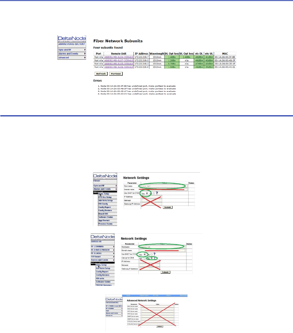
FOI Fiber Network Subunits
ThispageprovidesavisualindicationonthefiberlinkstatusforeachconnectiontotheFOI.
Figure 86
123456 7 8
FOI Fiber Network Subunits
Item Description
1SelectingtheremotelinkwilldirectthebrowsertotheRemoteUnitpage.
2NetworkIPaddressoftheFOIcard.
3OpticalwavelengthofthetransmitlaserintheFOIcard.
4 SubcarrieropticallossbetweentheFOIandFORinthedownlinkpath.
5 SubcarrieropticallossbetweentheFORandFOIintheuplinkpath.
6
SubcarrierpowertothemodeminthedownlinkpathoftheFOR‐Range
shouldbe‐30to‐60.Ifthelevelistoohighortoolowcommunicationand
othersystemproblemsmayoccur.
7
SubcarrierpowertothemodemintheuplinkpathoftheFOI‐Rangeshould
be‐30to‐60.Ifthelevelistoohighortoolowcommunicationandother
systemproblemsmayoccur.
8MACaddressoftheFOIcard
DASSoftwareConfiguration
80
Figure 87 DOI401 FOI Fiber Network Subunits
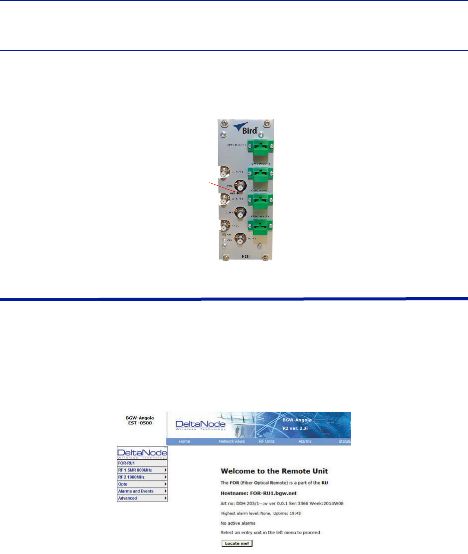
FOI Network Setup
Thispageallowsformanualoverrideofnetworksettings.DefaultconfigurationsshouldbeusedwithDHCPsetto
Yes.
Note: ChangingDHCPto“No”cancauselossofcommunicationstotheBIUandshouldonlybeusedin
veryspecificsituations.DonotenterIPconfigurationdatainotherassociatedsettings.
Figure 88 FOI Network Settings
FiberDistributedAntennaSystem(FiberDAS)
81
FOI Reset to Factory Default
ToresettheFOItofactorydefault,carefullypressthe“Reset”button(see
Figure89
)for10seconds.Thisishelpful
whenacardfailstoappearintheConfigurationmenu.
Figure 89 FOI Reset Button
Reset
FOR
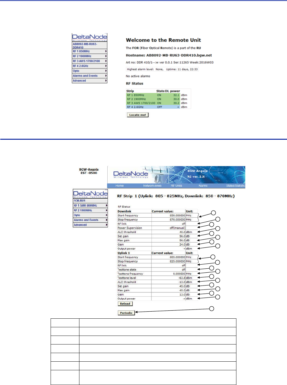
TheinitialscreenfortheFORprovidesbasicinformationsuchasname,serialnumber,partnumberandactive
alarms.TheLocateme!buttoncausesanLEDtoflashonthechassissothattheunitcanbeidentifiedinthefield.
Note: IfthefiberisjustnowconnectedtotheFOIcard,itcouldtakeupto30minutesfortheFOIto
assignanIPaddresstotheFOR.Seesectionfor
"MovingRemotestoDifferentFOIPort"onpage92
for
detailsonhowtoquickentheIPassignment.
Figure 90 FOR Welcome Screen
DASSoftwareConfiguration
82
Figure 91 FOR Welcome Screen
RF Strip 1 XXX MHz Status
Figure 92 FOR RF 1 Status
1
2
3
4
5
6
7
8
9
10
11
12
13
17
14
18
16
15
19
Item Description
1DownlinkfrequencybandfortheRFpath/stripselected
2RFlinksettingforthedownlinkpath:OnorOff.
3SettingofthedownlinkALCthreshold.
4DownlinklowpoweralarmturnedOnorOff.
5GainsettingfortheRFpathunderreview.
6Maximumallowedgainwillalwaysbethesameasthesetgainexceptin
specialbuilds.

FiberDistributedAntennaSystem(FiberDAS)
83
RF Strip 1 XXX MHz Configuration
Figure 93 FOR RF 1 Configuration
1
2
3
4
5
6
7
8
9
10
11
7
Theamountofactualgainusedbythesystem.Mightnotachievemaxgain
settingifALCisinoperation.Ifthesetgainis56asitisabove,RFisturned
onandtheactualgaininline7islessthan56thenthesystemisbeing
overdrivenandALCiskickingin.Reducegain.Suggeststartingwiththe
valuedisplayedinline7sincethisisthemostgainthatisbeingused.
8 Outputpoweroftheamplifierforthepathunderreview.
9UplinkfrequencybandfortheRFpath/stripselected
10 RFlinksettingfortheuplinkpath:OnorOff.
11 Statusofuplinktesttonesignal.Testtoneautomaticallyturnsoffafter60
minutes.
12 Uplinktesttonefrequencysetting.
13 Uplinktesttonelevel.Notadjustable.Accountsforlossesininternal
duplexers,ifany.
14 UplinkALCthresholdsetting.
15 Gainsettingintheuplinkpath.
16 Maximumallowedgainsetbythesystem.
17 Actualgainbeingusedintheuplinkpath.Thefiguremightnotmatchgain
settingifALCisinoperation.
18
UplinkoutputtotheFOI.
Note: IftheuplinkpathissettoOffareadingof“<“is
returned.
19 Periodicenablesaconstantupdateofthestatusscreen.
Item Description
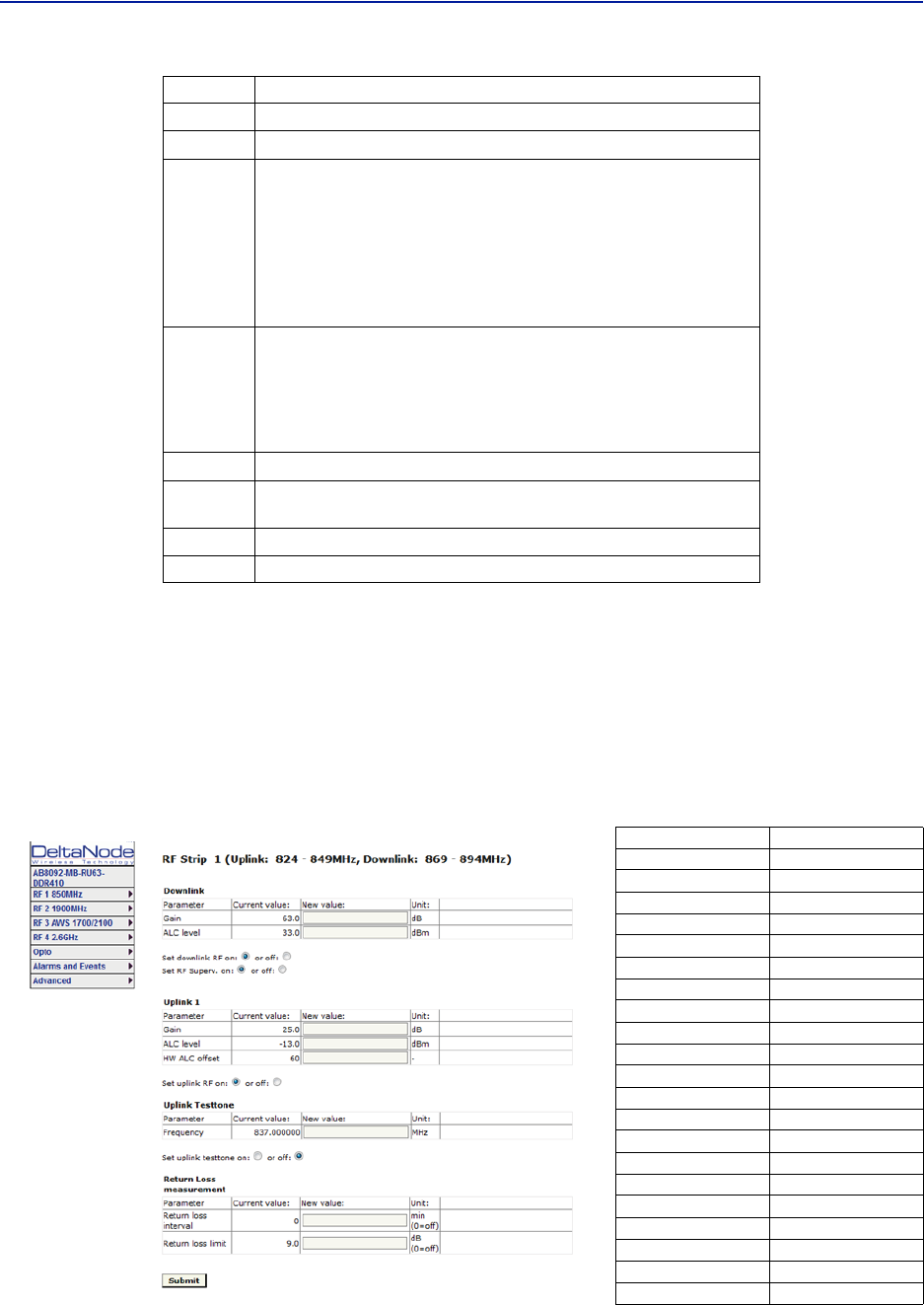
1DownlinkgainsettingforRFpathunderreview.
2
DownlinkALCsettingforRFpathunderreview.Thefactorydefaultissetat
theratedpoweroftheremoteunit(i.e.DDHissetto43dB).Thelevelcould
besetlowerforspecificsituations.Notethatthefactorylevelissetatthe
antennaport.Ifremoteisshuttingdownduetobeingoverdrivenitis
suggestedtoreducetheALClevelbyoneortwodBtoreducethenumberof
alarms.
3 TurnsdownlinkRFonoroff.
Item Description
DASSoftwareConfiguration
84
RF Strip 1 XXX MHz Configuration Software Version 3.9
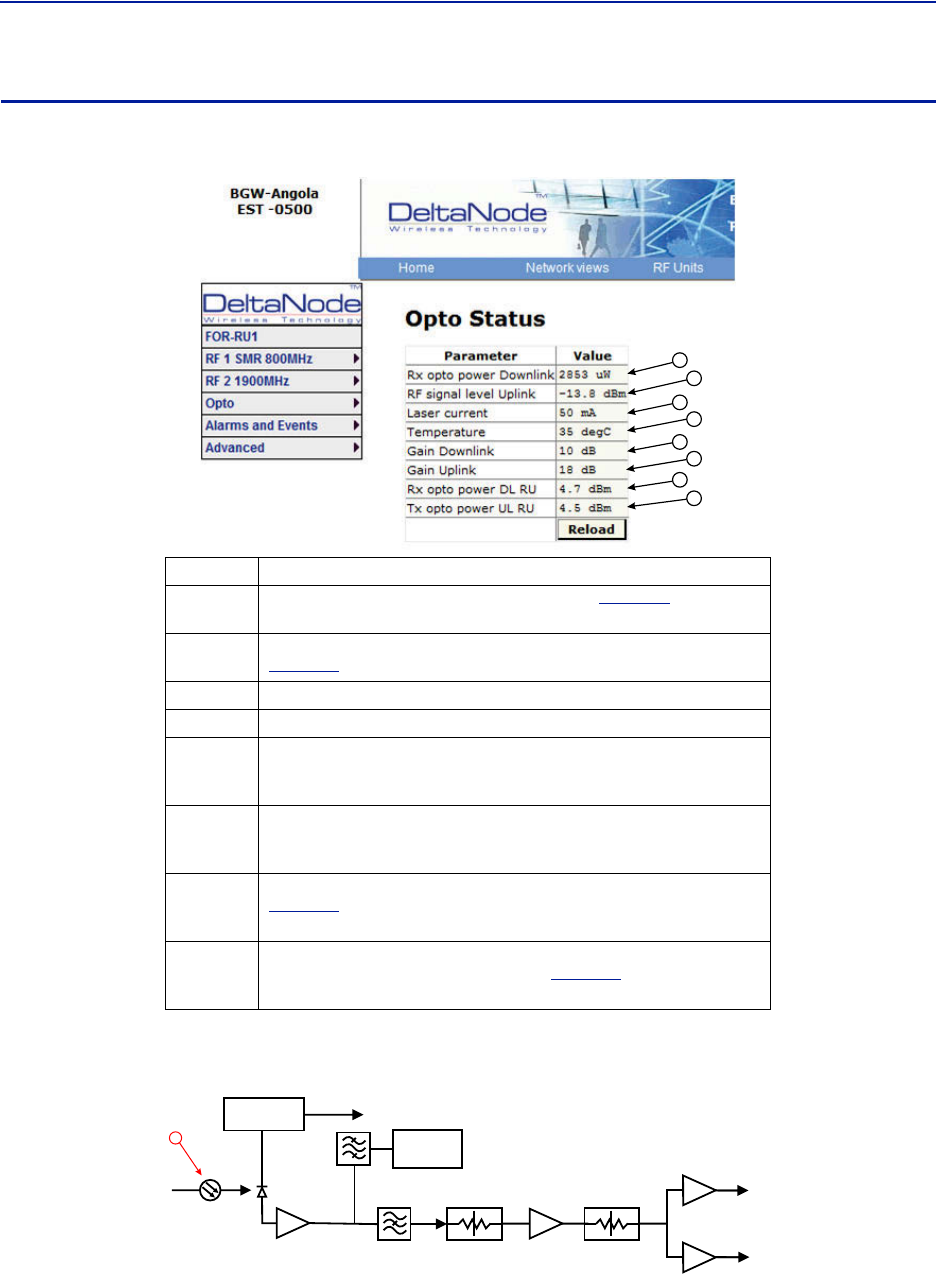
Softwarerelease3.9introducessettableReturnLossmeasurementsandcontroloveralarms.Thedefaultinterval
settingis“0”indicatingthereturnlossalarmfeatureisturnedoff.Returnlossalarmsareoftendisabledwhenthere
isapassiveantennanetworkinstalledbeyondtheremote.
ThedefaultReturnLosssettingis"9".Theremotewillstartshuttingdownand/orPAdamagecanresultwitha
returnlossoflowerthan6.
Figure 94 FOR RF 1 Configuration, Software Version 3.9
4 Turnsdownlinklowpoweralarmonoroff.
5UplinkgainsettingforRFpathunderreview.
6
UplinkALCsettingforRFpathunderreview.Thisisthethresholdatwhich
thesystemwillstartreducingfurthergaintopreventincreasesinuplinkRF
totheFOI.After10dBdecreaseingainanuplinkalarmwillbetriggered
Note: Shouldbeleftafactorydefault.OnlychangeifFOR
uplinkgainischanged.IfgainisincreasedonFORuplink
thenthesamevalueshouldbedecreasedontheALC.
Example:ChangingtheULFORgainfrom12to17wouldrequireALCtobe
changedfrom‐13to‐18.
7
HardwareALCoffsetmeasuredintenthsofadB.Defaultsettingof60
(6dBm)shouldbeusedformostapplications.Shouldthesoftwarenotbe
abletoreduceuplinkgainfastenoughaftertheALCthresholdhasbeen
exceed,hardwareattenuationwillbeaddedtoprotecttheuplinkpath.In
theexampleabove,thehardwareattenuationwilltriggerat‐7dBm(‐13dBm
ALCthresholdminus6dBmHWALCoffset=‐7dBm)
8 TurnsuplinkRFonoroff.
9Setsuplinktesttonefrequency.Mustbewithinuplinkfrequencylimitsof
theRFmodule.
10 Turnsonuplinktesttone.Testtonetimesoutafter60minutes.
11 RetrievescurrentFORsettingsfromsystem.
Return Loss (db) VSWR
9.542 2.00
9.262 2.05
8.999 2.10
8.752 2.15
8.519 2.20
8.299 2.25
8.091 2.30
7.894 2.35
7.707 2.40
7.529 2.45
7.360 2.50
7.198 2.55
7.044 2.60
6.896 2.65
6.755 2.70
6.620 2.75
6.490 2.80
6.366 2.85
6.246 2.90
6.131 2.95
6.021 3.00
Item Description
FiberDistributedAntennaSystem(FiberDAS)
85
FOR Opto Status
Figure 95 FOR Opto Status
1
2
3
4
5
6
7
8
Figure 96 FOR Downlink Schematic
CURRENT
SENSOR
ETHERNET
MODEM
OPTO IN
RX-LVL
RF OUT 1
RF OUT 2
PHOTO
DETECTOR
STEP ATT STEP ATT
1
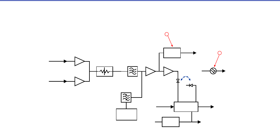
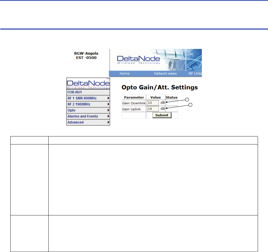
Item Description
1OpticalpowerreceivedfromtheFOI.Seeitem1in
Figure96
for
measurementlocation.
2UplinksignalbeingfedintotheFORuplinklasercircuit.Seeitem2in
Figure97
formeasurementlocation.
3LasercurrentfortheRemoteUnitFOR.Shouldbelessthan50mA.
4TemperatureoftheRemoteUnitFORboard.
5
Tota lgainoftheFORinthedownlink.NotethatRFOut1and2arewide
band(FMto2600MHz)thatfeedbandspecificRFamplifiersinthefollowing
VGAstage.
6
Tota lgainoftheFORintheuplinkpath.NotethatRFIn1andIn2arewide
band(FMto2600MHz)thataresignalsfromtheuplinkfrequencyspecific
amplifiers.
7
CalculateddownlinksignalbeingreceivedfromtheFOI.Seeitem1in
Figure96
formeasurementlocation.Takesintoconsiderationoptical
wavelengthandtemperaturecompensation.
8
CalculateduplinksignalbeingtransmittedtotheFOI(FORinputfromVGA+
FORuplinkgain/attenuation).Seeitem3in
Figure97
formeasurement
location.
DASSoftwareConfiguration
86
Figure 97 FOR Uplink Schematic
LOG
DETECTOR
VOLTAGE
INVERTER
LASER
DRIVER
ETHERNET
MODEM
OPTO OUT
TX-CURR
MONITOR
DIODE
LASER
DIODE
TX POW
TO
PHOTO DIODE
TX-LVL
+5 V -5 V
RF IN 1
RF IN 2 STEP ATT
2
3
FiberDistributedAntennaSystem(FiberDAS)
87
FOR Opto Gain and Attenuation Settings
Figure 98
1
2
FOR Opto Gain Settings
Asettingof+20indicatesnoattenuationsoFORwillhave+20dBgain(+20dBgainminus0dB
attenuation).
Asettingof+10willhave10ofattenuationsothisstagewillhave10dBmofgain(+20dBgainminus
10dBofattenuation).
Asettingof0willhave20dBofattenuationsothisstagewillhaveunitygain(+20dBgainminus
20dBofattenuation).
Asettingof‐10willhave30dBofattenuationsothisstagewillhave10dBofloss(+20dBgainminus
30dBofattenuation).
Asettingof‐20willhave40dBofattenuationsothisstagewillhave20dBofloss(+20dBgainminus
40dBofattenuation).
Asettingof+20willhavefullgainof+20dBm.
Asettingof+10willhave+10dBgain.
Asettingof0willhavenogain.
Factorydefaultshouldbeusedunlesshighlossinfiber.NotethatchangesinGainuplinkwill
requirechangesintheFORULALClevel.
Item Description
1
FORgaininthedownlinkpath.Rangeistypicallyfrom‐20to+20.FORdownlinkpathhasinherent/rawgainof
+20dB(FMto2600MHz).
2
FORgainintheuplinkpath.Rangeistypicallyfrom0to+20dBm(FMto2600MHz).
DASSoftwareConfiguration
88
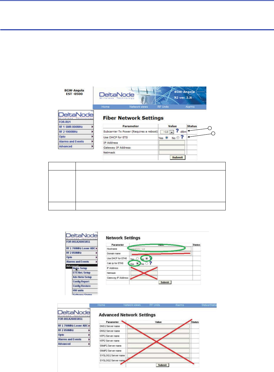
FOR Fiber Network Settings
Thispageallowsformanualoverrideofnetworksettings.DefaultconfigurationsshouldbeusedwithDHCPsetto
Yes.
Note: ChangingDHCPto“No”cancauselossofcommunicationstotheBIUandshouldonlybeusedin
veryspecificsituations.DonotenterIPconfigurationdatainotherassociatedsettings.
Figure 99 FOR Network Settings
1
2
Figure 100 More FOR Network Settings
ITem Description
1
SubcarrierTxPowerisusedforthecommunicationsandcontrolsignalingof
theDAS.Defaultsettingis‐10.Thevaluemayneedtobechangedin
situationswherefiberlossisnearthemaximumandcommunicationsissues
arise.UnnecessarilyincreasingthesubcarrierTXpowermayaffectRF
performanceoftheDAS.
2D
efaultseeingofYesshouldbeusedexceptforspecialapplications.
FiberDistributedAntennaSystem(FiberDAS)
89
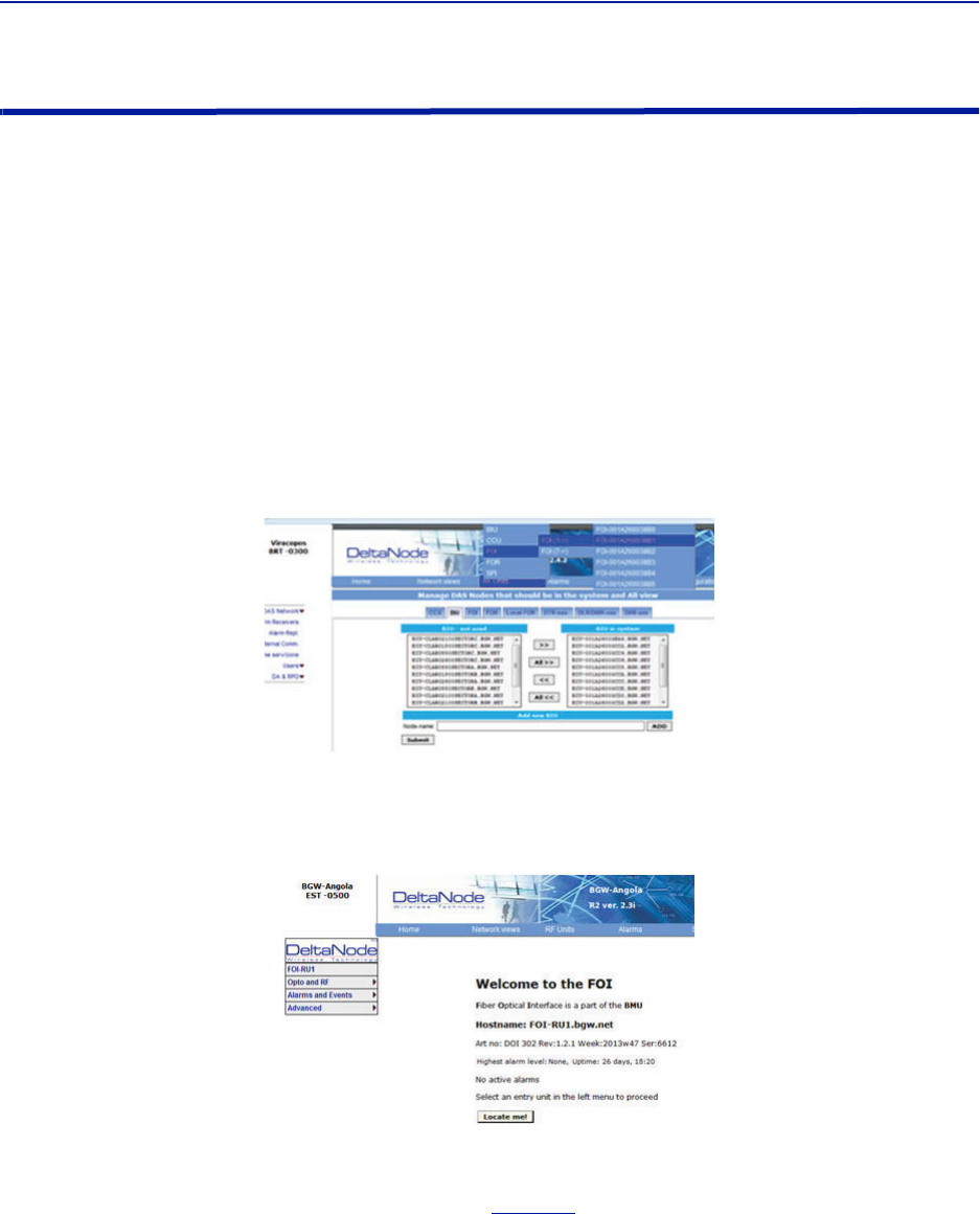
FOR Application Handling
Theapplicationhandlingpageallowsforsoftwareresetandrebootingfunctions.
Note: OnlytheRebootcommandshouldbeusedbythetechnician.Allotherfunctionsshouldonlybe
usedundersupervisionofBirdengineeringastheymaycausedatacorruptionifnotinitiatedproperly.
Figure 101 FOR Application Handling
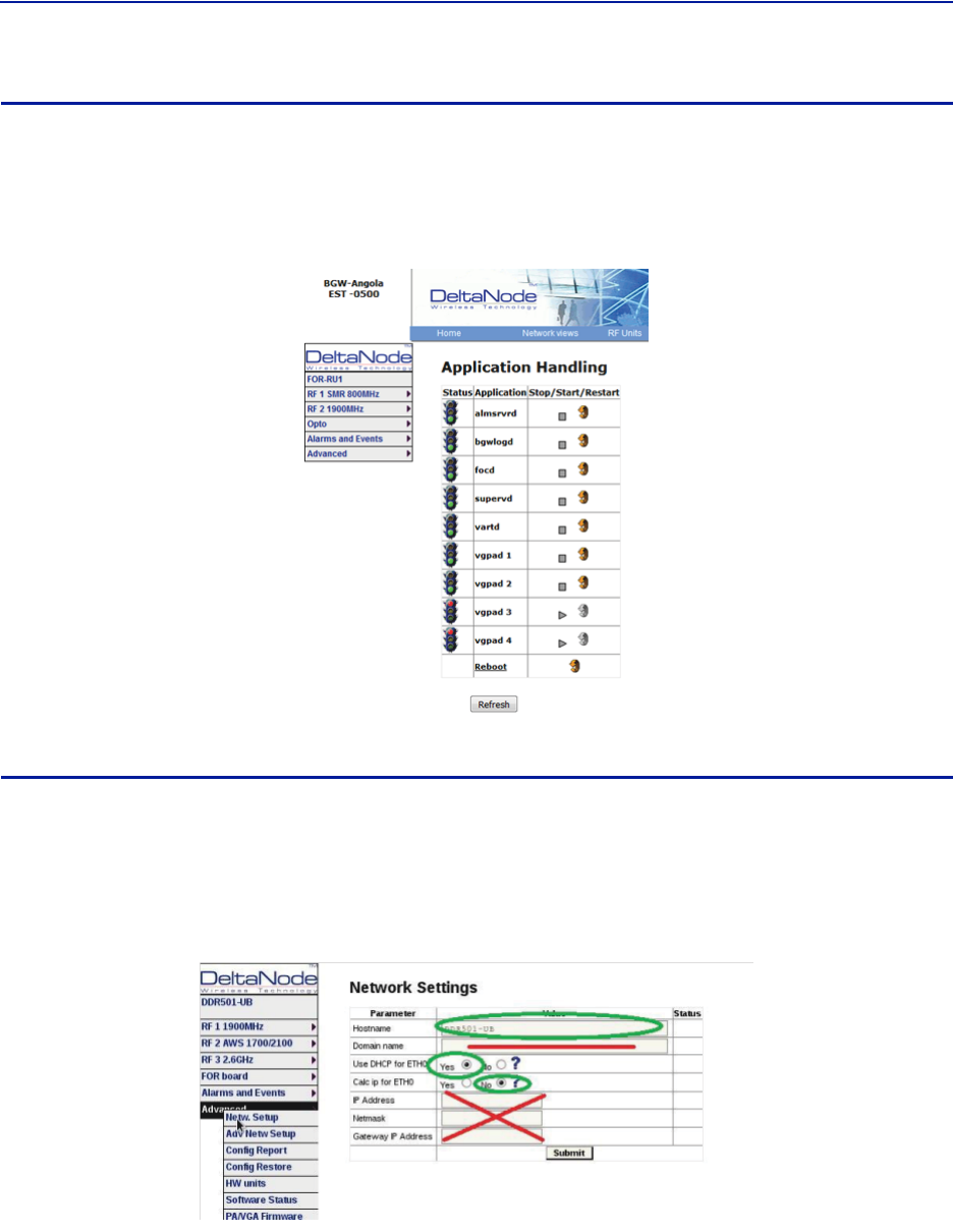
Slave FOR
ASlaveFORiswhenaremotehasasecondFORinstalled.TheSlaveFORismostlikelytobeusedwhentheremoteis
configuredforMIMOorhasmultipleamplifiersinthesamebandorhasredundantfiber.
SettingsfortheSlaveFORisthesameasthemainFORexcept,“CalcipforETH0issetto“No”.
Figure 102 Slave FOR Network Settings
DASSoftwareConfiguration
90
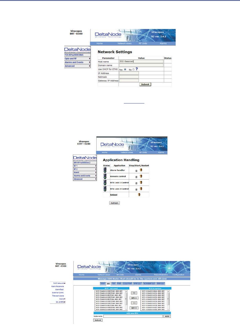
Naming Components
PropernamingofindividualcomponentsintheDASiscriticaltotroubleshooting.Arecommendationistostartall
componentnameswiththeirfunctionsuchas"BIU","FOI"or"FOR".Forexample:"BIU‐850Sector1".
Youmayuseanycombinationofalphanumericcharactersandthespecialcharacterofdash"‐".Donotuseany
otherspecialcharactersorspace.
0through9
athroughz
AthroughZ
‐
Componentnamesarelimitedto56characters.
1. SelectthecomponenttobenamedfromtheConfigurationmenu.
Figure 103 Component Selection
2. UsetheLocateMebuttontoverifywhichcardsisbeingaccessed.
Figure 104 Locate Me Button
3. GotoAdvanced>NetwSetup
4. EnterthenewcardnameintheHostNamefield.See
Figure105
.
5. Selectsubmit.
FiberDistributedAntennaSystem(FiberDAS)
91
Figure 105 Unit Naming
6. GotoAdvanced>Applrestart.
7. SelecttheRebooticonatthebottomofthemenu.See
Figure106
.
8. Select"YES‐RestartProcess"
Note: Afterrebooting,itcantakeupto5minutesbeforetheunitshowsupintheGUI.
Figure 106 Naming Reboot
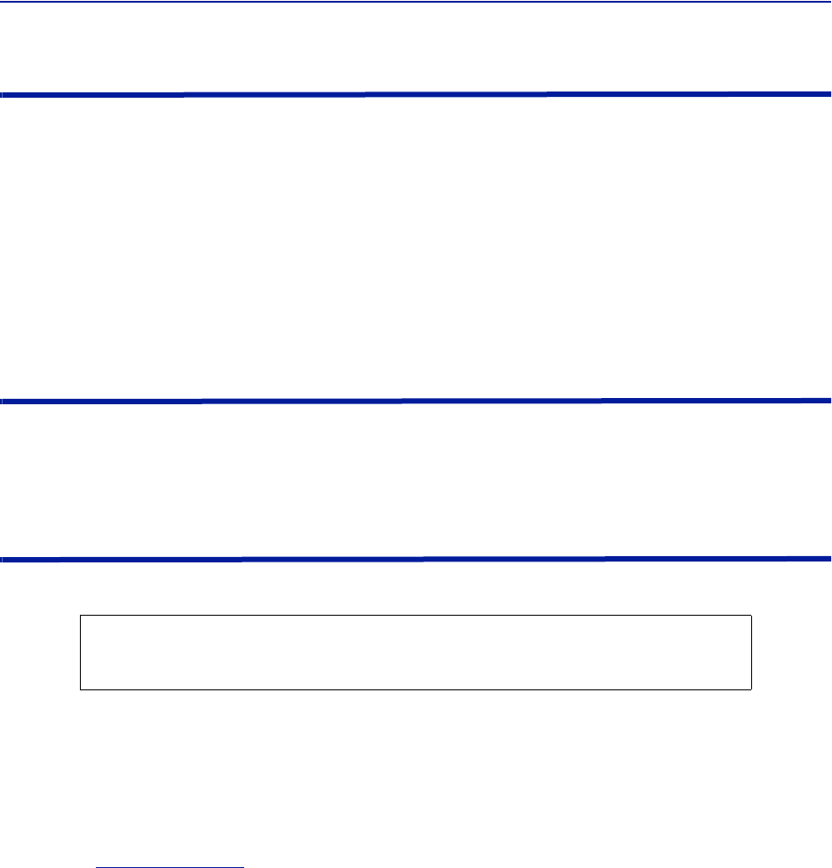
9. Afteralltheunitshavebeenrenamed,gototheConfigurationmenuandselectthecorrectcardtype.
10. Highlightallthecardsintherightcolumnthathadnamechangesandthenselect“<<“.Select“Submit”
ThiswillremovetheoldnamesfromtheDASConfiguration.
11. Highlightallthecardsintheleftcolumnwiththenewnamesandthenselect“>>”.Select“Submit”.
ThiswillmovethenewcardnamesintotheDASconfiguration.
Table 67 Submit Newly Named Units
12. SelectNetworkViews>Alltoconfirmthatallcardsarenowpartoftheconfiguration.
DASSoftwareConfiguration
92
Moving Remotes to Different FOI Port
AllDAScomponentsareassignedIPaddressesbytheBGW.TheFORintheRemoteistheassignedanIPaddressasa
subunitoftheFOItowhichitisconnected.WhentheRemoteismovedtoadifferentFOIoneofseveralactionsmust
takeplace:
1. TheleaseontheRemoteIPaddressmustbegiventimetoexpire.Thiscouldtakeupto30minutes.Oncethe
currentIPleaseexpires,thenewFOIwillthenassignthecorrectIPaddresstotheRemote.
2. ManuallypowercycletheRemote.Duringtherebootprocess,theRemotewillreleasetheoldIPaddressand
havethecorrectIPaddressassignedbythenewFOI.
3. CommunicationstotheremotecanonlyoccurwhentheremotehasthecorrectIPaddress.Beforemovingthe
fiber,accesstheFORviatheGUI.Intheadvancedsettings,reboottheFOR.Assoonasthereboothasbeen
initiated,quicklymovetheheadendfibertothenewFOIport.WhentheRemotefinishestherebooting
process,thenewFOIwillassignthecorrectIPaddress.
Replacing Master Unit Cards
AllDAScomponentsareassignedIPaddressesbytheBGW.Whenacardisreplaced,thecardmustbeassigneda
newIPaddressbytheBGW.Onrareoccasions,theBGWmayhavenotbeabletoassignanIPaddresstothenew
card.ThisiseasilycorrectedbyremovingthecardfromtheMasterUnitchassis(withESDstrapattached)andthen
re‐installthecard.TheBGWwillthenassignthecorrectIPaddress.
Moving Master Unit Cards
Occasionally,cardsneedtobemovedtodifferentslotsintheMasterUnit.
1. Movethecardtothenewslot.
2. EnsurethereisanEthernetconnectionforthenewcardlocationonthebackplaneoftheMasterUnit.
3. Waitforthecardtocompletethebootprocess.Ifthecardremainsinthebootprocess(GreenLEDremainson
forapproximately2secondsandthenoffforonesecond)thentheIPaddressmaynothavebeenassigned.
CheckEthernetconnection.
4. LogintotheGUItoconfirmsoftwareconnectivity.Onoccasionsthecardwillnotshowupafterbeingmoved.
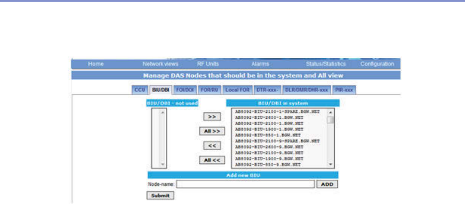
a. GototheConfigurationmenuandremovethecard(movefromrighttoleft)andthenSubmit.See
Figure107onpage93
.
b. Selectthecardfromtheleftmenuandthenadditbacktothesystemontherightandthensubmit.
c. GototheHomemenu.LogoutoftheBGWandthenlogbackin.
d. GotoNetworkViewsandlogintothecardtoverifyGUIconnection.
CAUTION
AlwaysuseanESDstrapwheninstallationandremovingcards.Failuretocomplymayresult
inpermanentdisablingdamagetothemodule.
FiberDistributedAntennaSystem(FiberDAS)
93
Figure 107 Manage System Modules

94
Chapter 5 Commissioning
Preparations
Theminimumofpreparationsnecessaryaretohavethesystemdocumentationwhichshouldincludethefollowing
itemsatleast:
Thesystemlayoutandblockschematic
Aconnectiondiagramforthehead‐endMasterUnit
Thetypeofconnectorsandtappersusedtointerfacetothebasestationports
ThenumberofcarriersforeachoftheBIUthatthebasestationsconnectsvia
Maximumoutputpowerforeachservicefromthebasestations
Fiberlossesshouldbedocumentedbeforehandsothatyoucancomparewhatthesystemactually
measures
Sectorizationinformation,whichsectorsshouldgotowhichremotes
DAScalculatorsheetsshowingtheexpectedsettingsforeachoftheRFchainsinuplinkanddownlink.
InformationaboutEthernetconnectionifthesystemshouldbemonitoredbyremote.Howtoconnectitto
theInternetforremoteviewingunlessyouareusingamodem.
Necessary tools
Thetoolsnecessarytocommissionthesystemincludes:
Onelaptopforchangingthesystemsettings,checkinganyalarmsandstatus.Onlysoftwareneededisa
webbrowser.OperatingsystemcanbeWindows,LinuxorMacasyouprefer.
Spectrumanalyzertomeasuretheuplink.Thesystemreliesontesttonemeasurementsintheuplinkand
thereforeitisimportanttohaveequipmenttomeasurethem.
SMAtooltobeabletoconnectordisconnectBTScablesfromtheBIU.
QMAadaptersoyoucanmeasuresignalsdirectlyonthehead‐endunitssuchastheFOI,BIU,ICUandso
on.
Software
Noparticularsoftwareisnecessaryexceptamoderngraphicalbasedwebbrowser.
FiberDistributedAntennaSystem(FiberDAS)
95
System Commissioning
Pre-requisites
EstablishEthernetconnectionbetweentheBGWandallcards
Powerupallequipment
EnsureIPaddresseshavebeenassigned
Cardswillbrieflyflashgreen.SolidgreenindicateswaitingforIPassignment
VerifyremoteunitfibersareconnectedtocorrectFOIports
Setnamesforallcomponentsandaddcomponentstothesystem‐See“NamingComponents”section
ConnectBTStotheBIUensuringproperattenuationfortheBIUcardbeingused
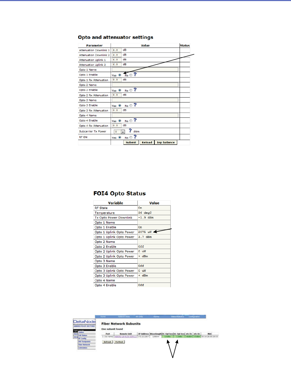
Commissioning Process
1. Oncethefiberisconnectedandverified,turnFOIRFpoweron.
Connectonlyonefiberportatatimeandcompletenamingofremote.Otherwise,asecondpersonwillbe
neededattheremotestoidentifytheremotewhen“LocateMe”isenabled.Thiscanbeeliminatedwithgood
projectmanagementandlabelingduringtheinstallationprocess.
Figure 108
FOI
RF
Control
FOI RF On
2. Enabletheappropriateopticalportsonthe4‐portFOI
Onlyenabletheopticalportsthatarebeingused.Otherwise,thesystemwillalarmwithlowopticallevelson
theunusedports.
Commissioning
96
Figure 109
Enable
FOI
Optical
Ports
Enable FOI Optical Ports
3. GotoFOIstatusandnoteRXOptopowerUL.
Thelasertransmitsat5000uW.Thedifferencebetweenthe5000uWtransmitlevelandthereceivelevelisthe
lossonthefiber.
Figure 110 RX Optical Power
RX
Optical
Power
a. Startingwithsoftwarerelease3.9,thereisanoptiontohavetheGUIcalculatethefiberloss.
Figure 111 Calculated Optical Loss, Software version 3.9
DL and UL
Optical
Loss

FiberDistributedAntennaSystem(FiberDAS)
97
Uplink
1. Setallvaluesatdefault(factorsettingmayvaryduetoindividualtestingbeforeshipping)forallbands
a. BIU:‐10dB
b. FOI:‐6,‐6,‐6
c. FOR:+12
d. Amp:+35forlowlossfiber,+45forhighlossfiber
2. Startwithadjustingthehighfrequencyband.
3. TurnRFonattheBIU.EnsurethatonlytheRFstripsbeingusedhaveRFturnedon.
4. GototheFORandturntheULtesttoneon.Notethelevelbeingtransmittedandthefrequency.Thelevelisset
atthefactorytocompensateforlossesbetweentheRUoutputportandtheamplifier.Levelswillvaryunitby
unit.
5. ConnectspectrumanalyzertotheBIUBTSportandtunetotheULtesttonefrequency.
6. Measurethetesttonelevel.InitialgoalshouldbetosettheULtesttoneattheBIUBTSporttothesamelevel
asbeingtransmittedattheRU(zerodBsystemgain).
a. Toreducegain,itisrecommendedtoadjusttheattenuatorsintheBIUULpath.Thiswillfurther
reduceULnoise.
b. Toincreasegain,itisrecommendedtoadjustthegainintheRUULpath.
Note: DonotdrivetheFORULlaserwithmorethan0dBmRFinput.RecommendedFORULinputlevel
isapproximately‐5dBm.
c. TheBIUULinputwillbepermanentlydamagedwithsignalsstrongerthan+13dBm.
7. RecordULtesttonelevelreceivedinthespectrumanalyzer.AfterallremoteunitsonthesectorhaveULlevels
set,theremoteswillneedtobebalancedagainsteachother(allarehittingtheBTSULatthesamelevel).
Levelsshouldbewithinabout1dBofeachother.
Downlink
1. Setallvaluesatdefault(factorsettingmayvaryduetoindividualtestingbeforeshipping)
a. BIU:‐15dB
b. FOI:‐3,‐3
c. FOR:+10
d. Amp:Tobesetbasedonactualinput
2. Suggestion:SetFORDLALCleveltoonedBlessthanampratingifunitalarmsonDL.
a. A43dBamplifierwouldhaveanALClevelsetto+42.
3. SetBIUDLleveltocompensateforICUinterconnectionloss.Donotexceed+10dBoutputoftheBIUintheDL
path(willcauseIM).
a. Suggestsettingatmaximumof+5dBoutputoftheBUI.
b. Notethereis13dBofinherentlossintheBIU.With0dBsettingsintheBIUDLattenuatorsa30dB
inputsignalwillhaveanoutputof+17dB(30dBinputminus13dBinherentloss=17dB).Adjust
attenuatorssothatBIUisapproximately+5dBasastart.
c. VariationsintheBTSinputlevelsforloadingmustbetakingintoconsideration.Fullloadandnoload
powerlevelsdiffergreatly.DonotallowtheBTStooverdrivetheBIU.
4. AdjustFOIattenuatorlevelsintheDLpathsothattheRFinputintotheDLlaserisapproximately‐5dB.
a. Notethatthe0dBmaxintothelaserisacompositelevelforallbands.Bysettingeachbandat‐5dB
thentotalcompositeshouldnotexceed0dB.
b. TakeintoconsiderationthateachBIUhastwoRFstrips/paths.Thesemustbetakenintoconsideration
whensettingtheFOIlevels.
c. CalculatefullloadconditionsforallbandsbeingfedintotheFOI.Incorrectlysettingthelevelswill
impactthesystemduringtimesofmostusage.
5. Setthedesiredgainintheremote.
Commissioning
98
6. ApplyRFsignaltotheBIUBTSport.
7. CheckRemoteUnitFORstatus"SetGain","Gain"and"OutputPower".
8. Adjust"SetGain"sothatdesiredoutputpowerisachieved.
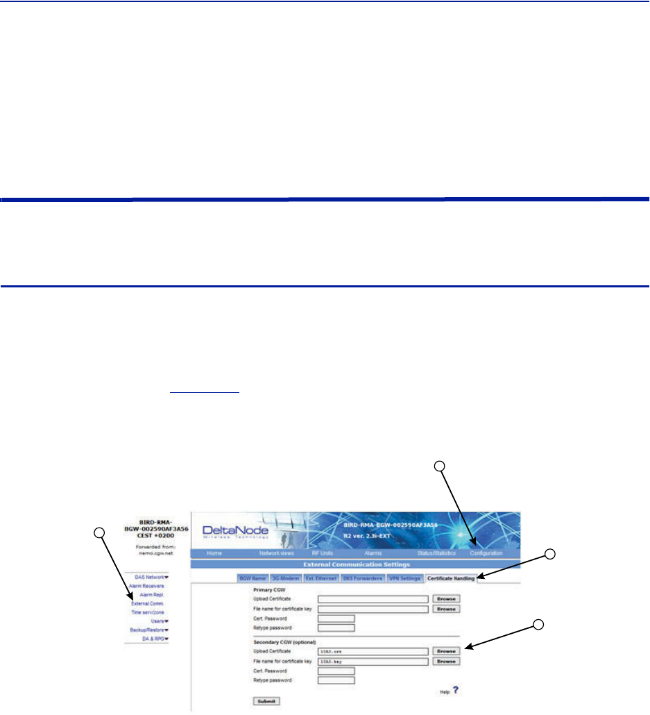
d. If"Gain"levelislowerthan"SetGain"levelinthestatusscreenthenthesystemisbeingoverdriven
andALCislimitingthegainofthesystem.Reducegainsettingtotheleveldisplayedin"SetGain".
Submitchangeandthereviewstatusscreen."SetGain"and"Gain"levelsshouldnowbeidentical.
Bird VPN Access
EstablishingsecureVPNaccessforBird/DeltaNodewillallowforremotemonitoringandadvancedtechnical
support.TheBGWisdesignedtocommunicatedirectlywiththeBird/DeltaNodeNOCviacloudaccess.
VPN Settings
1. ConnectlaptoptoanopenportontheDASswitch.DonotconnecttotheConsoleport.
2. LogintotheBGWat172.22.0.1.
LoginName:“extend”
Password:“admin”
3. Click“Configuration,”see
Figure112
.
4. Click“ExternalComm.”
Figure 112
3
4
5
6
Certificate Entry
5. Click“CertificateHandling.”
6. Click“Browse”nexttouploadCertificateforSecondaryCGW.
OnlymakesettingchangestotheSecondaryCGW.ThePrimaryCGWisreservedforcustomerCGWaccess.
FiberDistributedAntennaSystem(FiberDAS)
99
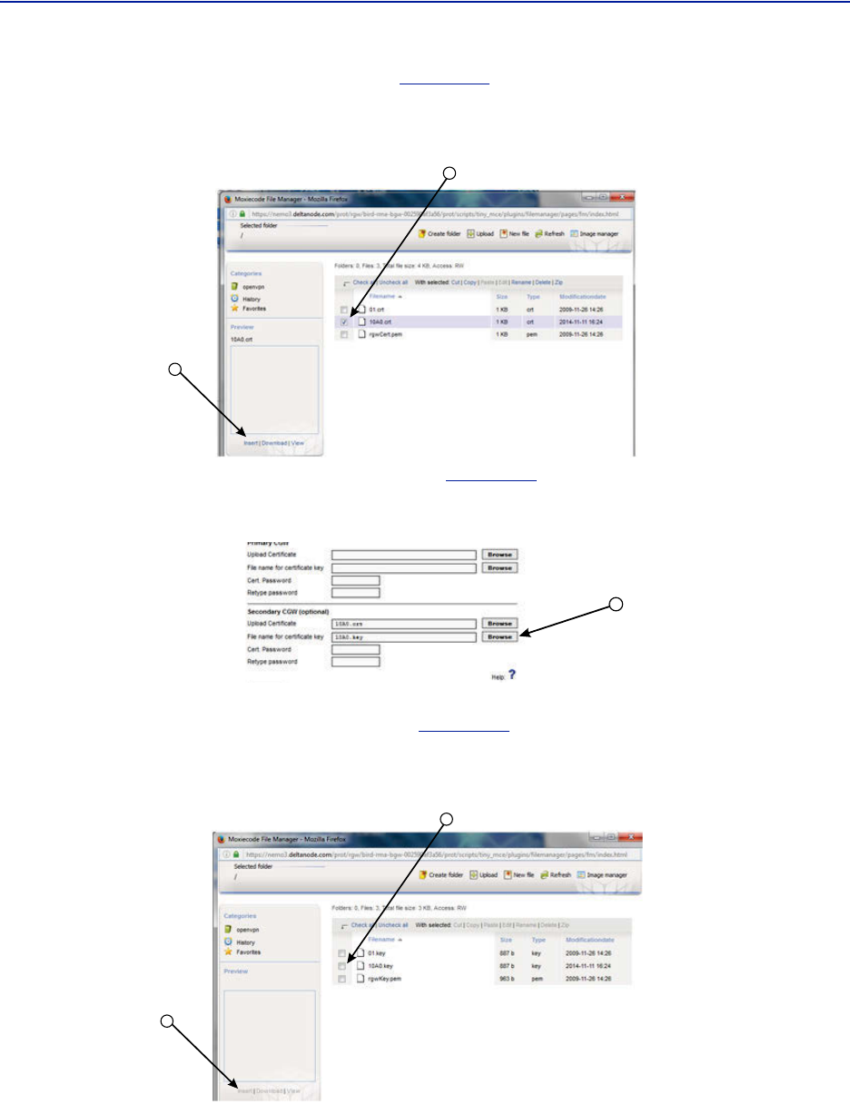
7. Selectthecheckboxnexttothe10##.crtfile.See
Figure113
.
8. Click"Insert"
Figure 113
8
7
Certificate Selection
9. Select"Browse"fortheFilenameforcertificatekey.See
Figure114
.
Figure 114 Key Entry
9
10. Selectthecheckboxnexttothe"10##.key"file.See
Figure115
.
11. Select"Insert"
Figure 115 Key Selection
11
10
Commissioning
100
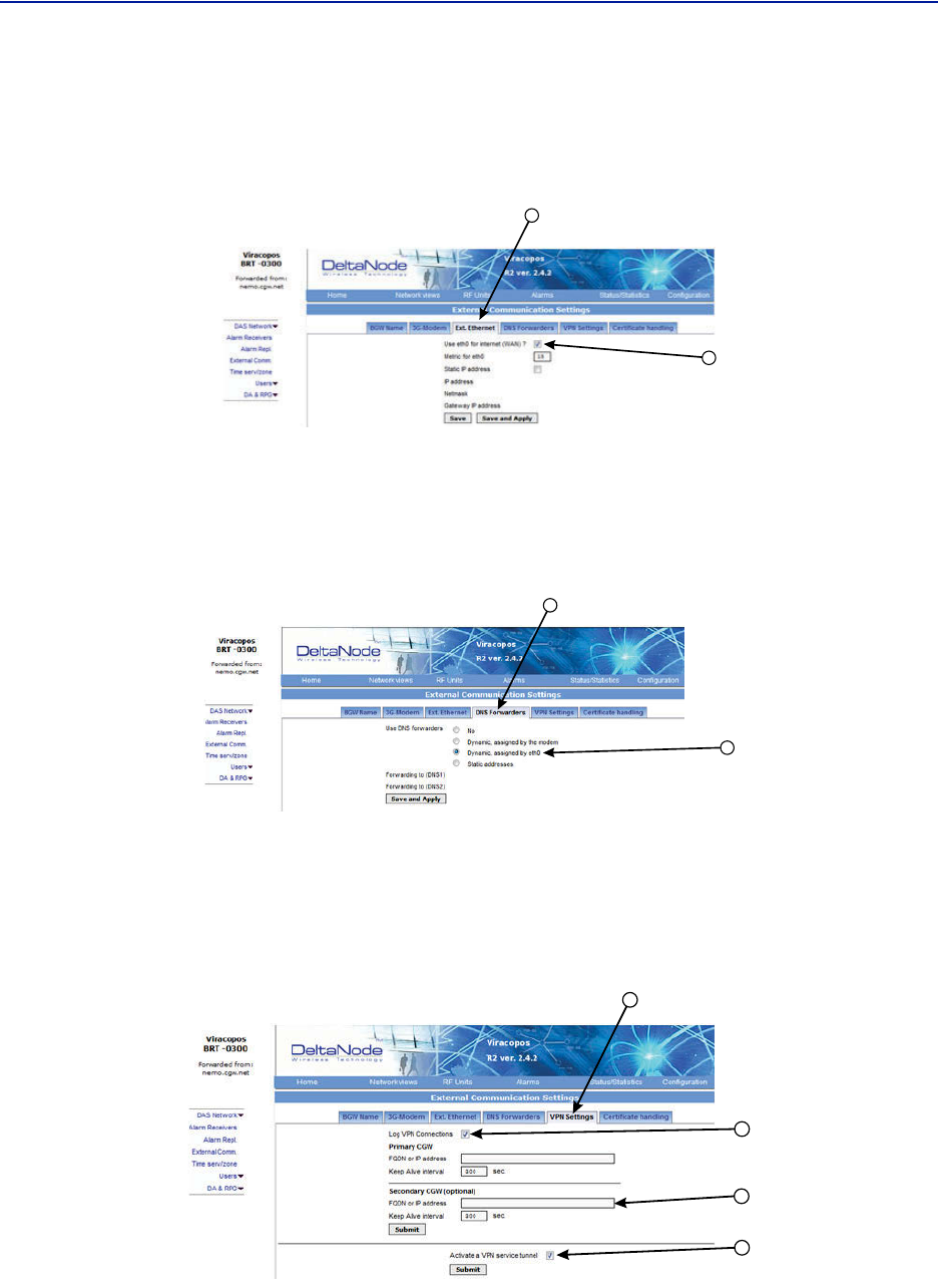
12. SelectExt.EthernetTab
13. Selectthecheckboxfor“Useeth0forInternet(WAN).”
ThisensuresexternalEthernetconnectionsareallowed.
Figure 116
12
13
External Ethernet
14. SelectDNSForwarderstab.
15. Selectradiobuttonfor“Dynamic,assignedbyeth0.”
Note: TheBirdmaintainedCGWisnotabletohostnamecheckaDNS2IPaddressof8.8.2.2,4.2.2.4or
4.2.25.PleasechangetosomethinglikeGoogle's8.8.4.4or8.8.8.8
Figure 117
14
15
DNS Forwarders
16. SelectVPNSettingstabtoverifythattheVPNsettingsarecorrectlyset.
17. Selectcheckbox“LogVPNConnections”
18. Type“nemo3.deltanode.com”intotheSecondaryCGWsettingforFQONorIPaddress.
19. Selectcheckbox“ActivateaVPNservicetunnel.”Thisselectionisonlyonavailableonoldersoftwareversions.
Figure 118 VPN Settings
17
18
19
16
nemo3.deltanode.com
FiberDistributedAntennaSystem(FiberDAS)
101
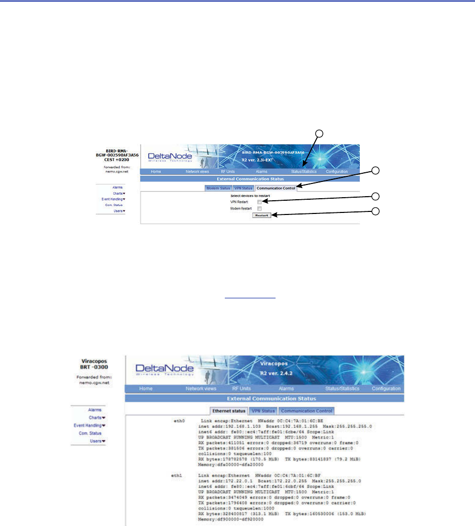
20. Clickon“Status/Statistics.”
21. Selectthe“CommunicationControl”tab.
22. Selectthecheckboxnextto“VPNRestart.”
23. Click“Restart.”
Figure 119
21
22
23
20
VPN Restart
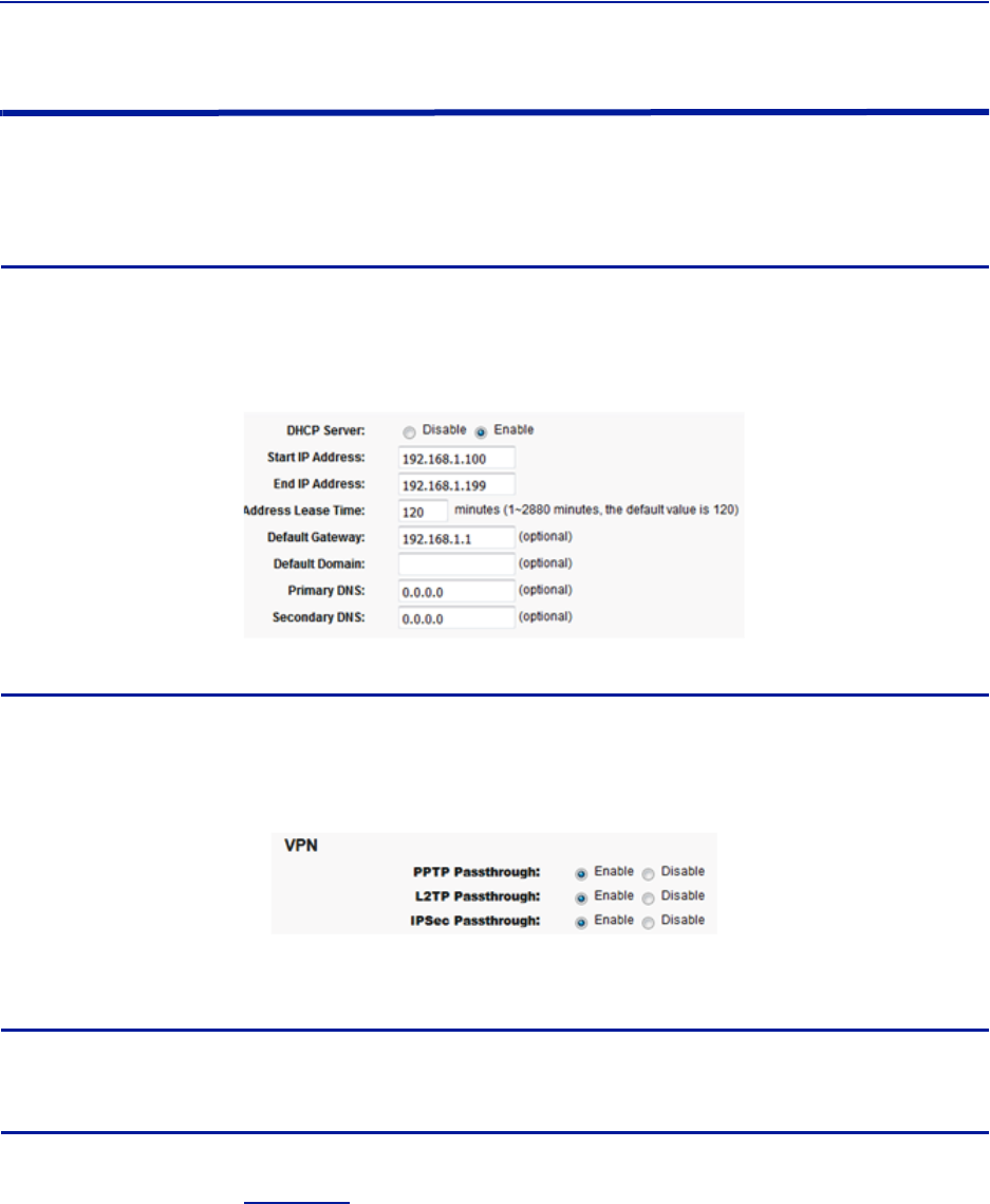
24. Afterabout10minutes,theBGWshouldstartcommunicatingwiththeBird/DeltaNodeCGW.
25. ClickonStatus/Statistics
26. SelecttheEthernetStatustab.
Both"eth0"and"eth1"shouldshowconnectivity.
Figure120
showsgoodcommunicationsin"eth0"between
theBGWanda3Gmodem."eth1"showsgoodcommunicationsbetweenthe3GmodemandtheBird/
DeltaNodeCGW.
Figure 120 Ethernet Status
Commissioning
102
Wireless Modem Setup
Duetovarianceswithdifferentwirelessmodemmanufacturers,settingsmayvaryfrommodemtomodem.A
generalunderstandingofnetworksettingsisrequired.Belowareafewtypicalsettingsthatwillneedtobe
configured.
Modem DHCP
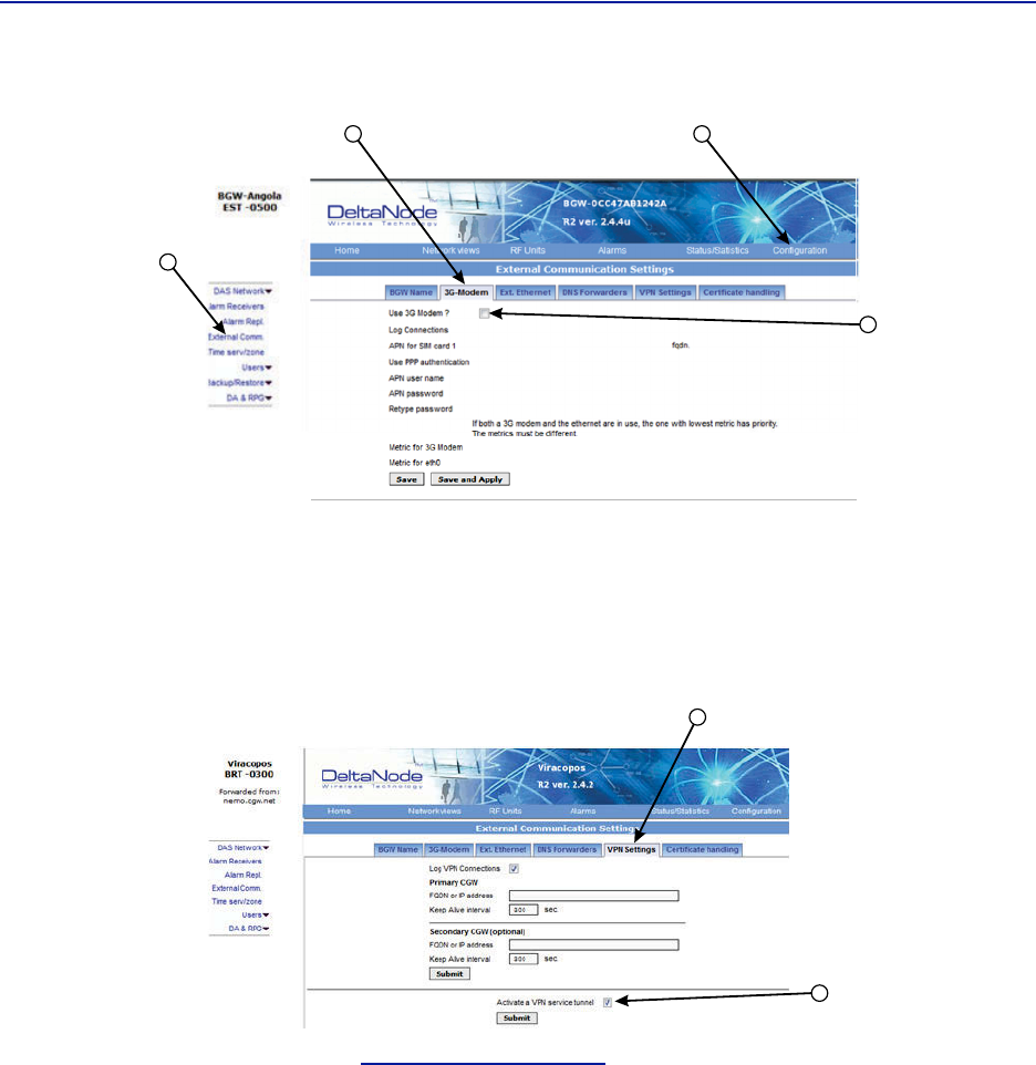
DHCPwillneedtobeenabledsothatthewirelessmodemcanassignanIPaddresstotheBGW.Besuretoenterthe
stopandendIPaddressasseenintheimage.
Figure 121 Modem DHCP Configuration
Modem VPN Tunnels
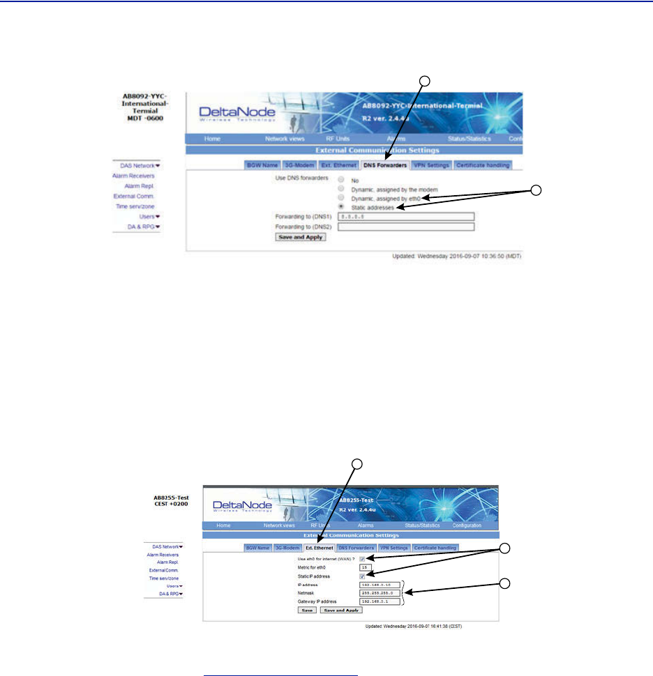
TheBGWcommunicatesbacktotheCGWviaaVPNtunnel.ThewirelessmodemmustenableVPNpassthrough.
Figure 122 Modem VPN Settings
Modem Port Forwarding
SetupthemodemsothatitforwardsTCPport443.
BGW Configuration
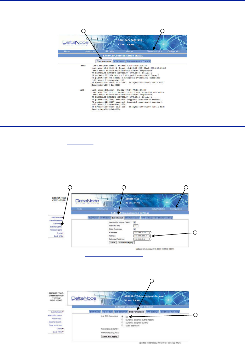
1. ConnectIPmodemtotheExternalWANportontheBGW.
2. ClickConfiguration.See
Figure123
.
3. ClickExternalComm.
4. Select3G‐Modemtab.
5. Selectthe“Use3GModem”checkbox.
FiberDistributedAntennaSystem(FiberDAS)
103
Figure 123
2
3
4
5
BGW Configuration - 3G Modem Setup
6. SelecttheVPNSettingstab.
7. Selectthe“ActivateaVPNservicetunnel”checkbox,ifnotalreadyselected.
Note: OldersoftwareversionsoftheBGWdonotofferVPNservicetunnels.ContactBirdtoordera
replacementBGW.
Figure 124
6
7
BGW Configuration - VPN Setting
8. SelecttheDNSForwarderstab.See
Figure125onpage104
.
9. Selecteither:
"Dynamic,assignedbyeth0"or
"Staticaddresses".Enter8.8.8.8intheForwardingto(DNS1).
Commissioning
104
Figure 125
8
9
BGW Configuration - DNS Forwarders Setting
10. SelecttheExt.Ethernettab
11. Select"Useeth0forinternet"and"StaticIPaddress"checkboxes.
12. RecordtheexistingIPsettingincaserollingbacktooriginalsettingsisrequired.
13. EntertheIPaddressesinformation:
IPAddress:192.168.0.10
Netmask:255.255.255.0
GatewayIPAddress:192.168.0.1
Figure 126
10
11
13
BGW Configuration - External Ethernet Setting
14. Afterallthesettinghavebeenconfigured,powercyclethewirelessmodem.
15. Clickon"Status/Statistics."See
Figure127onpage105
.
16. Selectthe"EthernetStatus"tab.
Verifiythat"etho"hasbeenassignedavalidIPaddress.
FiberDistributedAntennaSystem(FiberDAS)
105
Figure 127
1516
BGW Configuration - Ethernet Status
Rolling Back Modem Configuration
Iftheexternalmodemisnolongerrequiredtheconfigurationcanquicklyberolledback.
1. ClickonConfiguration.See
Figure128
.
2. ClickonExternalComm.
3. SelecttheExtEthernettab.
4. EnteroriginalIPaddressesthatusedpriortoinstallingthemodem.
Figure 128 Rollback Modem IP Addresses
4
12 3
5. SelecttheDNSForwarderstab.See
Figure129onpage105
.
6. Selectthe"No"radiobutton.
Figure 129 Stop DNS Forwarding
5
6
Commissioning
106
Setup local Network UDP Ports for CGW Access
InorderfortheBird/DeltaNodeCGWtobeabletomakecontactwiththeBGWensurethatthecustomerIT
departmenthasOpenVPNwithUPDports1194to1199.ThisallowsBird/DeltaNodestaticIPaddresstoaccessthe
BGW.
Local Connection to Remote Unit
Atechniciancandirectlyconnectalaptoptotheremoteunit.Thisisusefulwhenthetechnicianisattheremote
unittroubleshooting.Thedirectconnectionisalsoveryusefulwhenthereisnofiberconnectivitytotheremote
unitandtheinstallerneedstotestandprogramtheremoteunitduringtheinstallationprocess.
Note: Bydirectlyloggingintheremoteunitandprogrammingthenameoftheremotethereisless
chanceofconfusionwhenalltheremotesareconnectingtotheMasterUnit.
1. SetlaptoptoastaticIPaddress;somethingalongthelinesof
IPaddress169.254.48.11
SubnetMask255.255.0.0
Gateway169.254.0.1
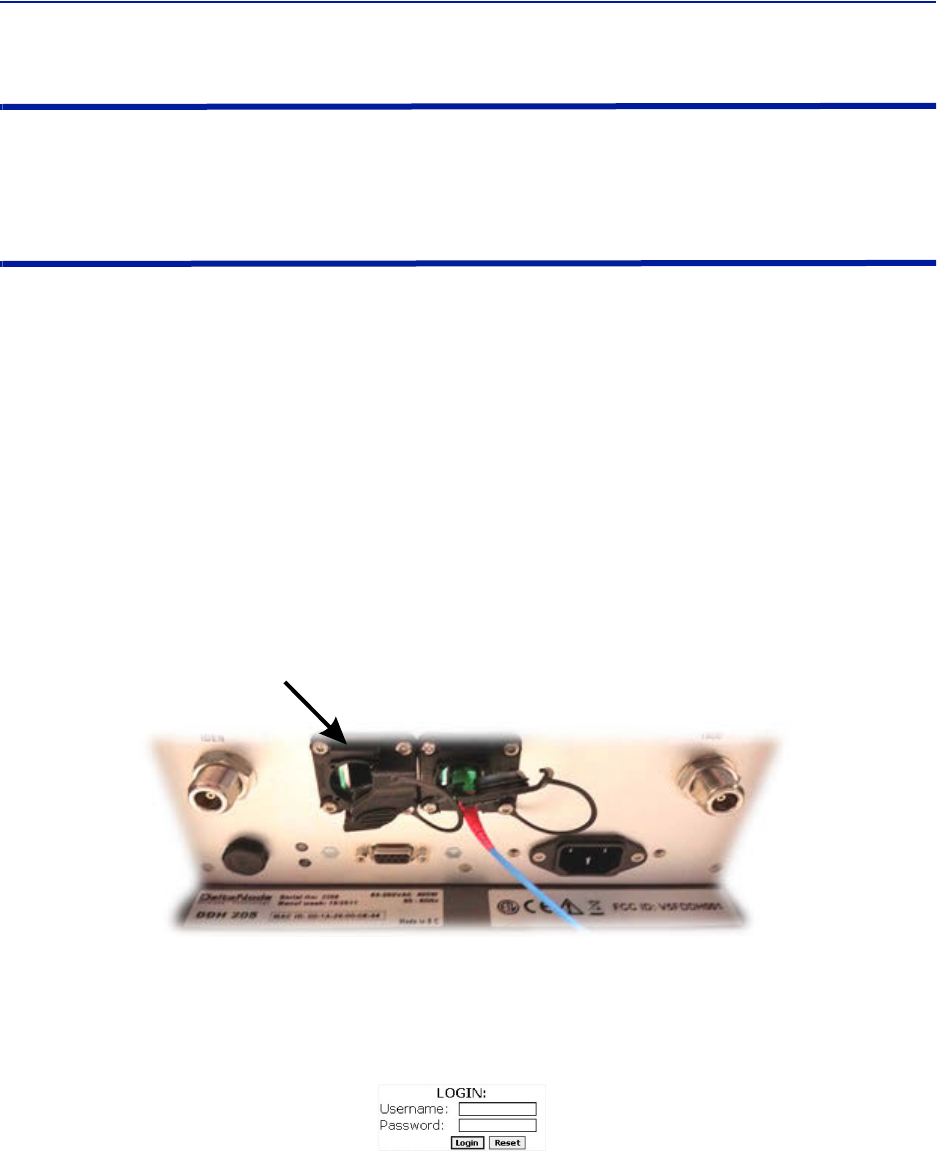
2. ConnectRJ45EthernetcabletothelaptopandtheEthernetportontheremote.
Figure 130 Remote Unit Ethernet Port
Ethernet
Port
3. Useanywebbrowsertoconnecttotheremoteunitstartingwithhttp://169.254.48.1.
TheremoteunithasadefaultIPaddressof169.254.48.1to.10.Iftheloginmenudoesnotappeartrythenext
sequentialIPaddress(http://169.254.48.2).ContinuetryingthenextIPaddressuntiltheloginmenuappears.
Figure 131 Remote Unit Login Screen
4. Whentheloginmenuappearstypeinthedefaultcredentials:
Username:“extended”
Password:“admin”
5. TheGUImenuswillbethesameaswhenconnectingtotheremotethroughtheBGW.

FiberDistributedAntennaSystem(FiberDAS)
107
Local Connection to Remote Unit with Two FOR's
Someremoteunitsarebuiltwith2FORboards.Thiswouldoccurinapplicationswhereonechassiscontains:MIMO
paths,multipleamplifiersofthesameband,amplifiersfedfromdifferentFOIcardsorotherspecialapplications.The
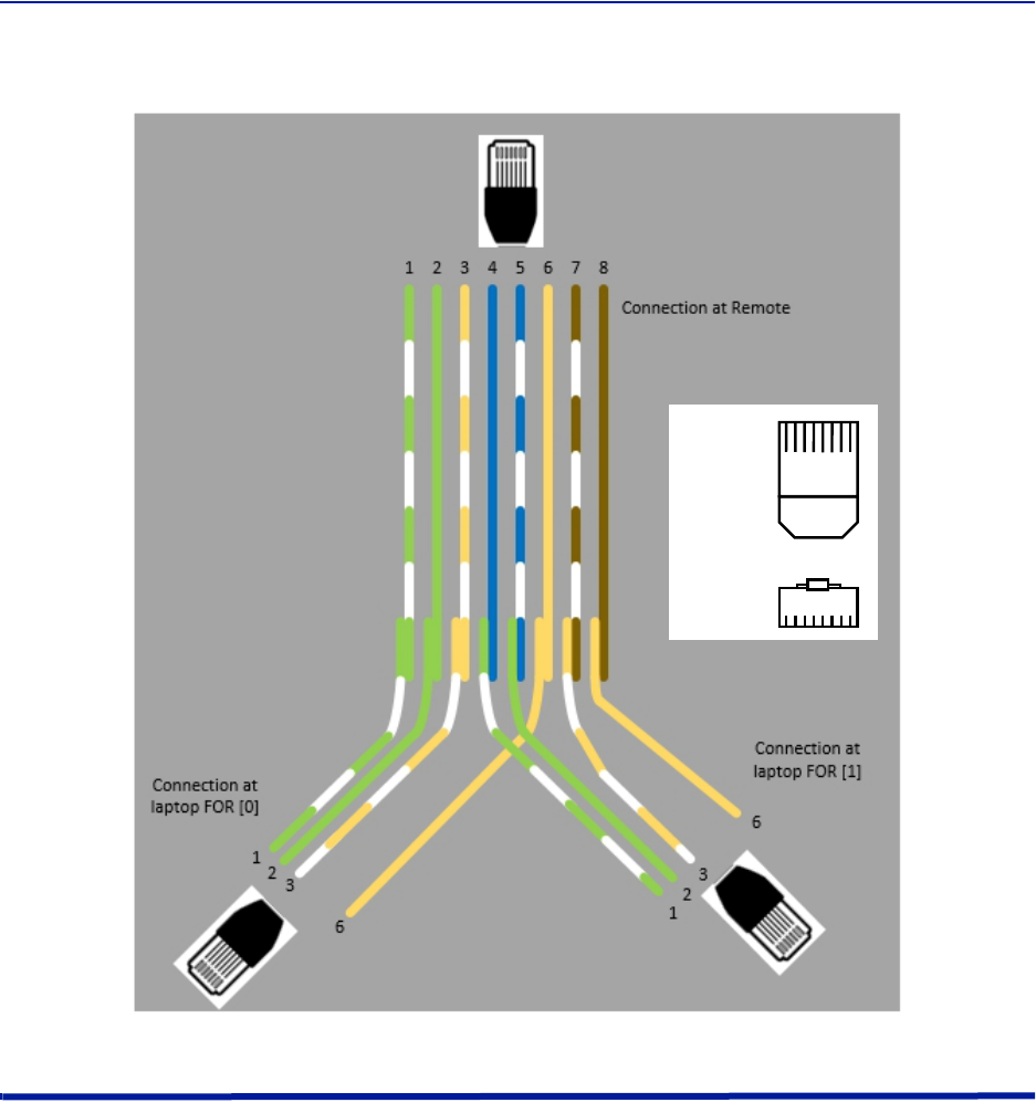
2FORboardssharetheoneEthernetconnectorontheremoteunit.AstandardEthernetcablewillonlyaccessFOR
[0].AcustomcableisrequiredtoaccessFOR[1]board.
TobuildacabletoaccessbothFORunitsyouwillneedthefollowingitems.
Wirecutters
Wirestrippers
Electricaltape
TwoEthernetcableswithRJ‐45Connectors
Build a Custom Cable
1. CutbothEthernetcablesinhalf.
Threesectionswillbeneeded.
2. Stripbacktheinsulationoneachwireabout0.5inch/13mm.
3. Twistthecolorpairstogetherasshownin
Figure132onpage108
.
4. Useelectricaltapetocovertheconnectionssobarewiredonottouch.
Unusedcablestrandscanbecut.
5. Securethesplicewithelectricaltapesothatstressdoesnotpullthewirepairsapart.
6. Clearlymarkeachconnectortodistinguishwhichconnectorisattachedtotheremoteandwhichconnector
plugsintothelaptopforFOR[0]andFOR[1].
Commissioning
108
Figure 132
123457
68
12345
78
6
Top:
Front:
Custom Cable for Connecting to two FOR systems
Connection to BGW from Remote Unit
ThetechnicianhastheabilitytoconnecttotheBGWfromtheremoteunit.Thiseasestroubleshootingand
programmingbynothavingtoreturntotheBGWlocationfordirectaccess.
1. EnablethelaptopDHCPsettings.
2. ConnectRJ45EthernetcabletotheEthernetportontheremote.
TheFOIwilldetectthatadevicehasconnectedtotheFORandwillassignanIPaddresstothe
thelaptopintherangeof172.22.108.49‐62.
Note: Itmaytakeupto15minutesfortheFOItoassignanIPaddresstothelaptop.
3. UsinganInternetbrowserconnectto172.22.0.1
4. Whentheloginmenuappearstypeinthedefaultcredentials:
Username:"extended"
Password:"admin".
109
Chapter 6 RF Commissioning
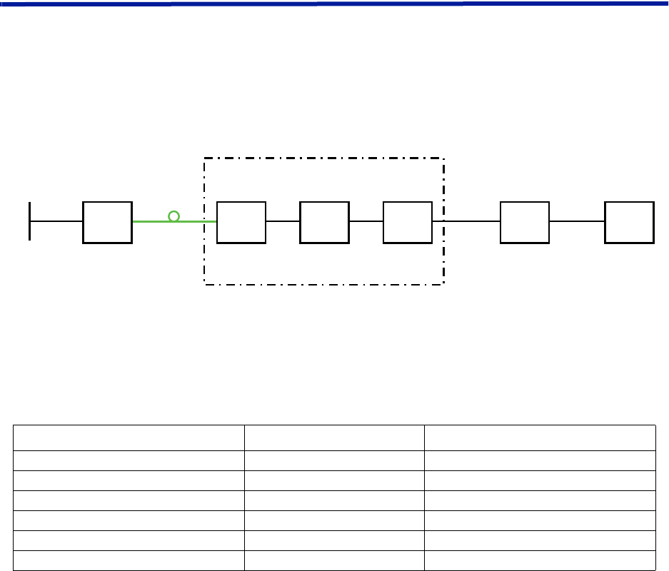
Inordertomaketheprocessmoreclearforthispartofthemanualwewillconsidersettingupafictitioussystem,
butbasedonastandardapproachatdoingFiber‐DAS.Thesystemthatweareconsideringwillhavetwofrequency
bands,let’sassumeGSM900MHzandUMTS2100MHz.Theexamplewillhave2sectorswithtworemotesineach
sector.Ofcourseyoursystemmaylookdifferent,bemoreorlesscomplexbutinordertomakeitclearhowthe
systemissetupthisshouldprovideyouwithastartingpoint.
Setting up the uplink
SettinguptheuplinkmeanstoadjustthesystemforanoptimalworkingpointfromtheantennaportoftheRemote
UnittotheactualinputontheRadioBaseStation.Thiscanbedoneindifferentwaysdependingonhowthesystem
isdesigned.Wewillherediscussastandardset‐upstartingwithasmallblockschematicshowinghowthesystemis
connected.
Figure 133
System Interconnect Diagram
Themainparameterthatwewillbediscussingisthe”netgain”ofthesystem.Thismeansthetotalchangeinsignal
fromtheRemoteUnitantennaporttothereceiverportonthebasestation.Therearedifferentwaysofsettingthis
systemupbutwewilllookata0dBnetgainsystemwhichisagoodstartingpointformostsystems.
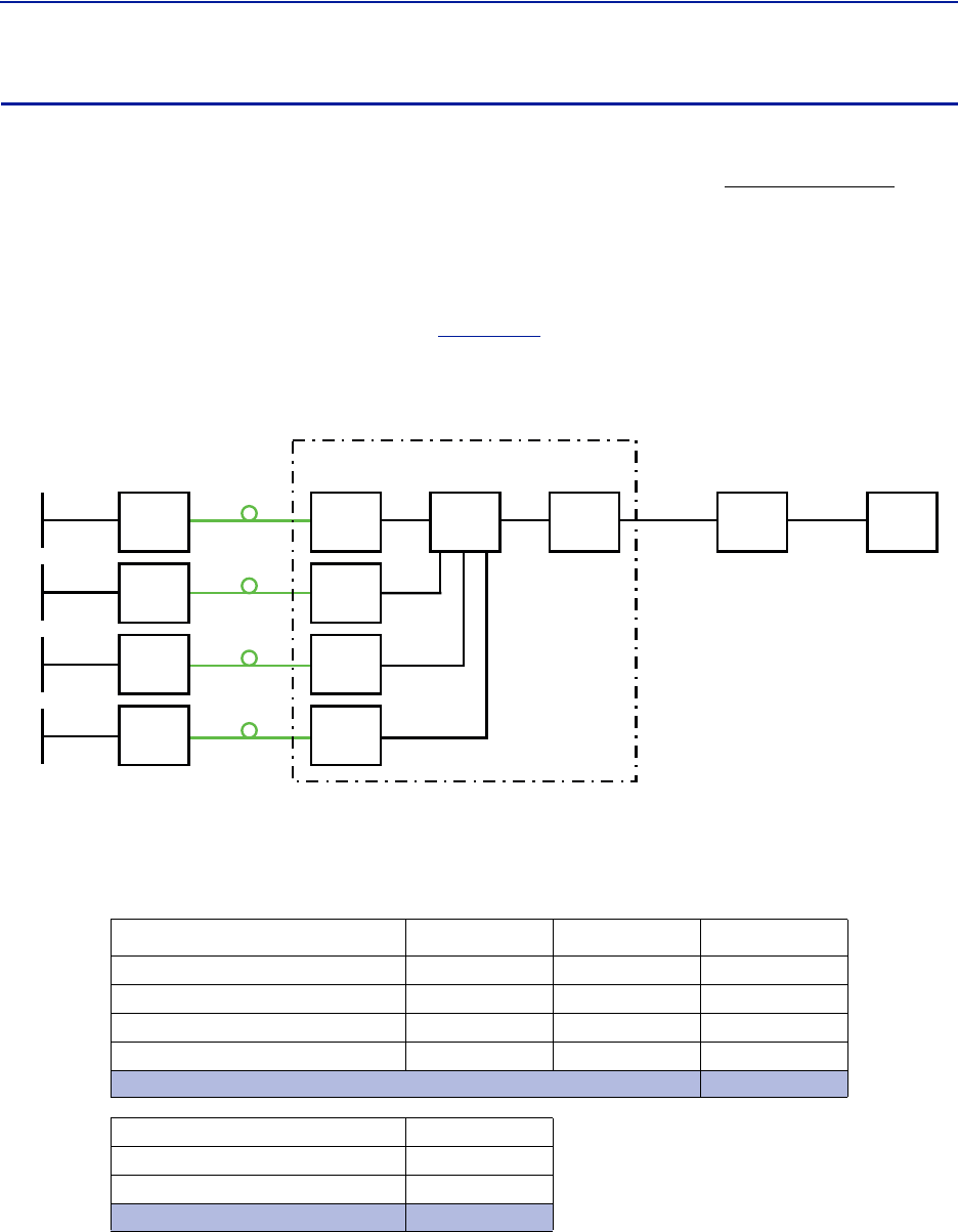
ThesystemgaincanbecalculatedasthegainintheRemoteUnit–Lossonfiber+FOIgain–ICUloss+BIUgain–
couplerloss.Basicallythistakesformofalinkbudgetandhereisanexample:
Table 68
Unit/Component Gain/Loss (dB) Accumulated Gain/Loss (dB)
RemoteUnit(RU)
Fiber‐OpticCable
FOI
ICU
BIU
Coupler
Example Link Budget
BasicallythismeansthatwhateverisinputattheantennawillalsobeseenatthesamelevelfortheRadioBase
Stationreceiver.Thisisnotabadstartingpointbutdoesnottakeintoaccountthenoiseloadonthebasestation
whichwillincreasesomewhatwiththissetup.
40 40
-10 30
20 50
-35 15
015
-15 0
RFCommissioning
110
Noise load on Radio Base Station
Thesystemwillinevitablyaddsomenoisetothereceiver.Whenproperlysetupthenoisefigureinasystemlikethis
willbebetterthan3dB.However,ifthegainisimproperlysetup(i.e.notenoughgainintheremote,toomuchgain
inthehead‐end)itispossibletocreateaverybadnoisefigure.InordertoavoidthistheFiber‐DASCalculatorshould
beusedtocalculatethenoisefigureofthesystemintheuplink.
IfyouhavenotfamiliarizedyourselfwiththeFiber‐DASCalculator,dosobeforemovingoninthismanual.The
figuresintheFiber‐DAScalculatorrelatetothesettingsofallstepsinthechain.Byusingthecalculator,youcan
determinethepropersettingsonceyouknowthefiberlossbetweentheRemoteUnitandtheheadend.
LetusassumeyourhavearrivedataNoiseFigure(NF)of3dBforthischain.Howeveryoursystemmaycontain
moreremotes,perhapsconnectedlikethesystemin
Figure134
.
Figure 134
!
Multiple RU Connection Diagram
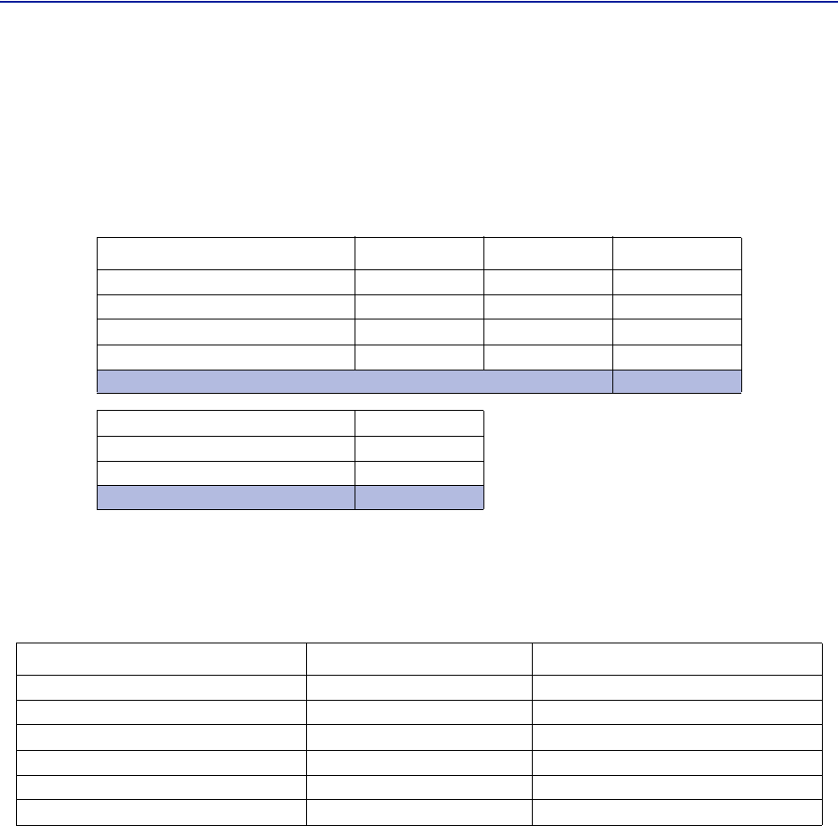
Nowthenoiseloadcanbecalculatedbyaddingthenoisecontributionfromeachstepofthechain.Belowisan
exampleofnoisefiguresfromeachoftheremotes:
Table 69
Chain NF Gain Noise Load
RU1
RU2
RU3
RU4
BaseStation
Fiber‐DASNoiseLoad
TotalNoiseintoBTS
Noise Load
AddyourfigurestothesheetintheFiber‐DAScalculatoranditwillcalculateitforyou.
2.8 0.0 2.8
3.2 1.0 4.2
3.8 -2.0 1.8
2.6 -1.0 1.6
Sum of Noise Load 8.7
4.0
8.0
9.5
Desensitization -5.5
FiberDistributedAntennaSystem(FiberDAS)
111
Whatweseehereisthatifwesetthesystemupinthisfashionwewilldesensitizethebasestationwithabout5,5
dB.ThiscanbeokayifthebasestationcoverageisonlythroughtheFiber‐DASsystembutifthebasestationisalso
beingusedforoutdoorcoverageitisnotgood.Weneedtochangethenetgaintoreflectthis.Ingeneralweshould
lowerthegainsothatwedesensitizetheBTSonlyabout3dB.Thisvalueisagoodcompromiseandsimilartoadding
asecondantennatothesamereceiverport(whichiskindofwhatwearedoingwiththeFiber‐DAS).
Herearethenewvalues:
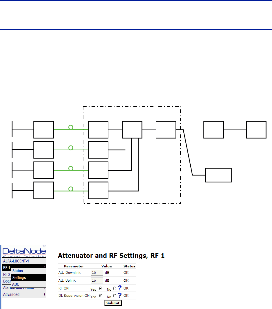
Table 70
Chain NF Gain Noise Load
RU1
RU2
RU3
RU4
BaseStation
Fiber‐DASNoiseLoad
TotalNoiseintoBTS
Adjusted Noise Load
Asyoucanseeweshouldsetthesystemupwithanetgainofabout‐5dB.Goingbacktothesettingswehadbefore
whichwas:
Table 71 Example Link Budget
Unit/Component Gain/Loss (dB) Accumulated Gain/Loss (dB)
RemoteUnit(RU)
Fiber‐OpticCable
FOI
ICU
BIU
Coupler
WeonlyneedtochangetheBIUsettingusingtheattenuatorsintheBIUtolowerthegainwith5dB.Thiswill
accomplishwhatweneedtodoandtheuplinkshouldthenbecommissioned.
2.8 -5.5 -2.2
3.2 -5.5 -1.8
3.8 -5.5 -1.2
2.6 -5.5 -2.4
Sum of Noise Load 4.1
4.0
4.1
7.1
Desensitization -3.1
40 40
-10 30
20 50
-35 15
015
-15 0
RFCommissioning
112
Practical approach
Nowthatweknowwhatweshouldhavewecaneasilysetthesystemup.Youneedaspectrumanalyzertodothis
anditiseasiesttoconnectitintotheBIUport.Rememberthatwhenyoumeasurehere,thesignalshouldalsogo
throughtheBTScouplerbeforeitreachesthebasestationreceiverport.Thereforeyoushouldexpecttoreada
valuethatis
Yourexpectedgain+thelossinyourcoupler
Ifyouwantanetgainof‐5dBandyouhavea15dBcoupler,youshouldreadanetgainof+10ontheBIUport.This
isnowwhatwearegoingtouseinthefollowingexample.
!
"#
Turn on the RF
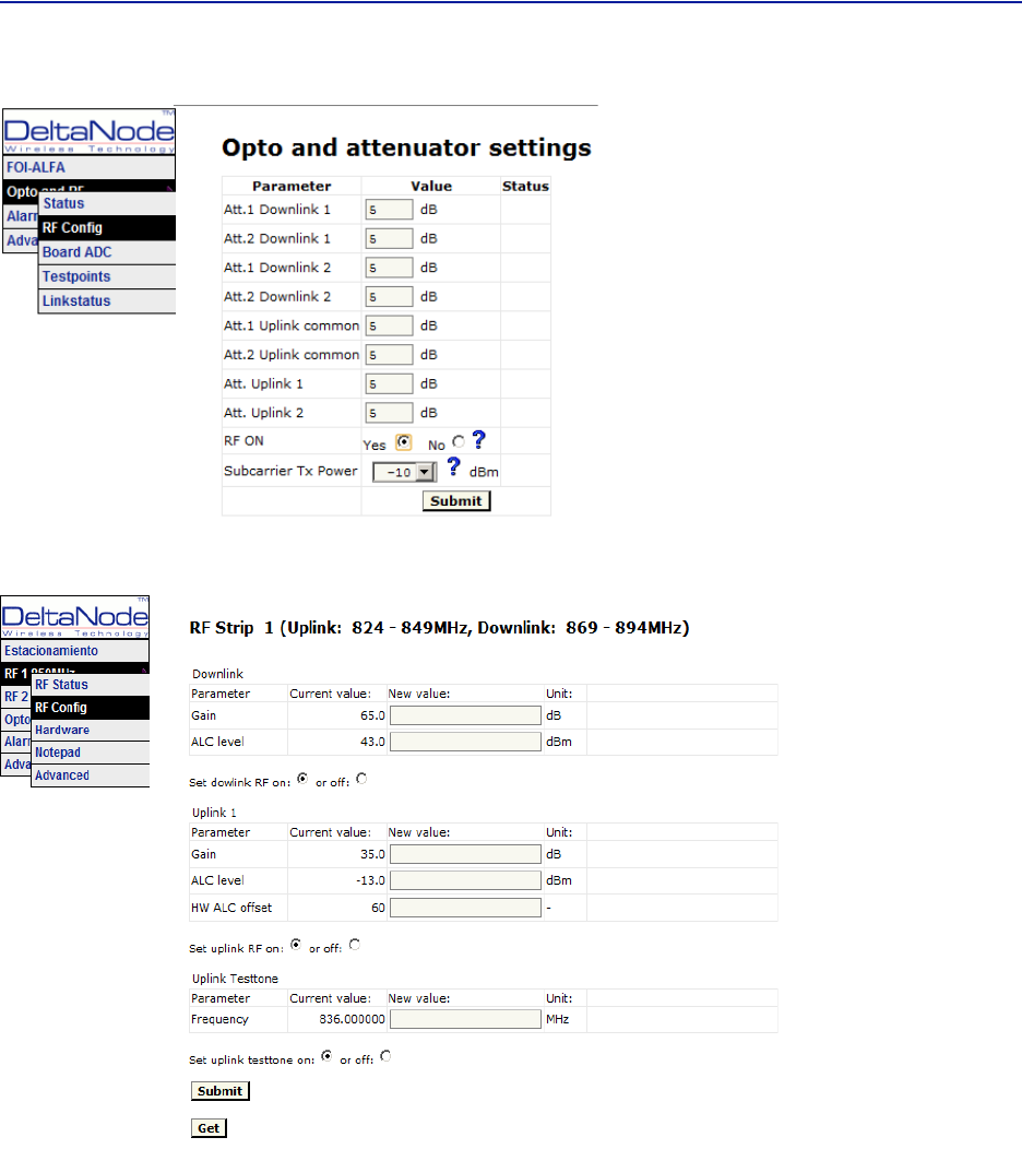
ConnecttotheBIUandturnontheRF.Settheattenuatorinthemediumrangefortheuplinkthatyouare
measuring.Thisallowsyoulatertoadjustitupanddownasnecessarytogetthecorrectgainfortheuplinkchain.
Settingthemto10dBisagoodidea.DLsupervisioncanbeleftasisfornowandalsoDLattenuationwhichwewill
setuplater.
ConnecttotheFOIcardandselectOptoandRF–RFConfigandsetitupaccordingtoyourFiber‐DAScalculator
settings.DonotforgettoturnRFon.
FiberDistributedAntennaSystem(FiberDAS)
113
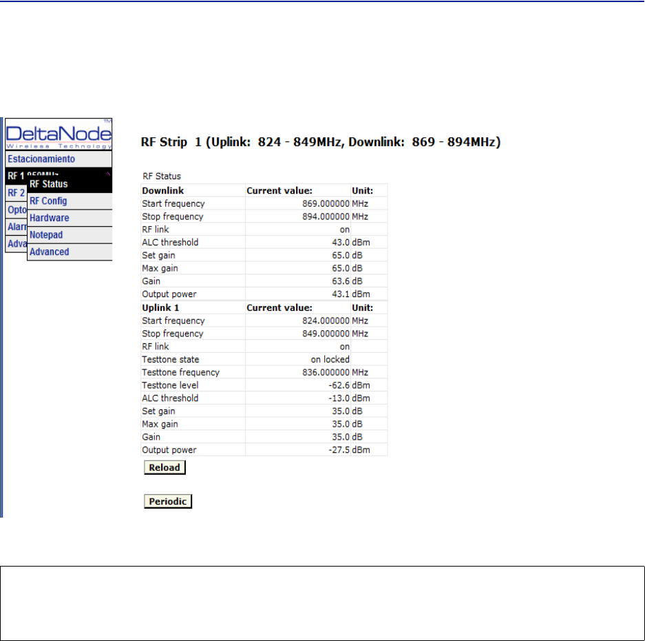
Nextstepistoconnecttotheremoteunitandsetitupfortestmeasurementintheuplink.
InthisscreenyoushouldalsoturnRFon,setthegaintoabout35dBasastartingpointandthenturnontheuplink
testtone.Notethefrequencyofthetesttone,thisisthefrequencyyoushouldbemeasuringonyourspectrum
analyzer.
RFCommissioning
114
Turnonthespectrumanalyzer,makesureitisconnectedtotherightportontherightBIUandthenfindthe
frequency.Areasonablespanis1MHzandthereceiverbandwidthcanbesetto30kHzorsimilar.Usethemarkerto
measurethepeakofthesignal.Thengotothenextscreenontheremoteunit,theRFStatusscreen.
WhatwearelookingforhereistheTesttoneLevel.Notethisdownaswell,nexttothefrequencyofthetesttone
younotedearlier.
Thencheckyourspectrumanalyzer.Assumingyourtesttonelevelis‐62,6dBmasinthisexampleyourspectrum
analyzermayshow‐58,2dBm.CalculatingthenetgainbetweentheRUandtheBIUwillthenyield‐58,2‐‐62,5=4,3
dB.SubtractthecouplerbetweentheBIUandtheradiobasestationwhichinthisexamplewas15dBandweget‐
19,3dBasournetgain.
Wewanted‐10dBsowehave9,3dBtoolowgain.Weshouldthenincreasethegainandthebestplacetodothis
wouldbeintheremoteunitbysettingthegainat35+9,3=44,3whichwewillroundto44dB.
Thatuplinkisnowfinishedandwewillrepeatthesettingsforallofouruplink,oneatatime.
CAUTION
TurnOffTestTone
Donotforgettoturnoffthetesttonewhenyouaredonewithyouruplink.Bettercheckoneextratime.Theywill
otherwiseinterferewiththenormaloperationofthesystembycausingnoisetothebasestation.
115
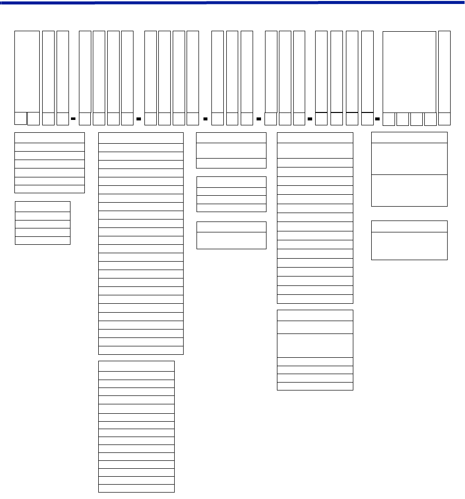
Chapter 7 Model Identification
System Model Numbers
Examples:
DDR4-GC0-PA1-AD — 4band,33dBmpoweroutputperband,Fullband700combinedwithCell850non
duplexed,PCScombinedwithAWSduplexed,ACpowered,7/1 6 DIN,1310nmuplink
DDR4-GC0-PA1-AD-B12-C34-WUBCS — 4band,33dBmpoweroutputperband,Fullband700combined
withCell850nonduplexed,PCScombinedwithAWSduplexed,ACpowered,7/1 6 DIN,Bands1and2(700and850)
1290nmuplink,Bands2and3(PCS&AWS)1310nmuplink,CWDM,fibersplit(3dB)fordaisychainedremotes
CWDM
Optical Split
Wavelength FOR 1
B
Voltage
A
FOR 1 Band 1
1
Connectors
D
WDM
W
Frequency
G
Frequency
C
Duplexed
0
Duplexed
0
Sub-family
R
Product Family
DD
Number of Bands
4
Frequency
G
Frequency
C
Duplexed
0
Duplexed
0
FOR 1 Band 2
2W B
UCS
C
Wavelength FOR 2
3
FOR 2 Band 1
H
Wavelength FOR 3
3
FOR 3 Band 1
Family:
DDU - 46 dBm Full Band
DDH - 43 dBm Full Band
DDS - 41 dBm Single Carrier
DDR - 33 dBm Full Band
DDL - 23 dBm Full Band
DDX - Mixed Power Levels
Frequency:
R - FM Radio
V - VHF (136-174)
T - Tetra (380-400)
M - Gov (406-420)
B - Tetra (410-415/420-425)
O - Tetra (415-420/425-430)
X - CDMA450 (453-457.5/463-467.5)
U - UHF (450-470)
Q - 500MHz T-Band (470-512)
L - Lower 700
H - Higher 700
G - 700 Full Band
F - PS 700 (793-805) FirstNet & NB
S - 800 SMR
J - DD 800
C - Cell 850
N - 900 PS
Y - GSMR
Z - EGSM900
D - DCS (1800)
P - PCS
I - UMTS (1900/2100)
A - AWS (1700/2100)
K - AWS & AWS3
E - IMT-E (2600)
Duplexed or DDX Pwr Lvl:
0 - Non-duplexed
1 - Duplexed
For DDX use:
For DDX Pwr Lvl 0 - 9:
0 - Non-duplexed (DDU)
1 - Duplexed (DDU)
2 - Non-duplexed (DDL)
3 - Duplexed (DDL)
4 - Non-Duplexed (DDH)
5 - Duplexed (DDH)
6 - Non-duplexed (DDS)
7 - Duplexed (DDS)
8 - Non-duplexed (DDR)
9 - Duplexed (DDR)
Number of Bands:
1
2
3
4
Voltage:
A - Universal AC
(86-264 AC/DC)
D - 48 VDC
CWDM (option):
WUxxxx - combine multiple
uplink fiber interfaces onto one
fiber - each x denotes a
wavelength (absence of xxxx
implies all UL wavelengths)
WDxxxx - split to multiple
downlink fiber interfaces from
one fiber - each x denotes a
wavelength (absence of xxxx
implies all DL wavelengths)
Connectors:
N - N-type Connectors
D - 7/16 DIN
M - Mini DIN
WDM:
W - Duplexed (UL and DL on
the same fiber)
Wavelength of Uplink:
(FOR2 and FOR3 are optional to
support multiple fiber links)
A - 1270
B - 1290
C - 1310 (default C if omitted)
D - 1330
E - 1350
F - 1370
G - 1390
H - 1410
I - 1430
J - 1450
K - 1470
L - 1490
M - 1510
N - 1530
O - 1550
P - 1570
FOR Bands:
(if omitted than all bands on one
FOR)
Bands for that fiber link (in order
as appear in model #)
i.e. C123 would be standard FOI
driving bands 1, 2, and 3
1
2
3
4
Optical Split (option):
Sx - split the fiber at entry - to
daisy chain other remotes - x is
dB split (3dB equal split if absent)
ModelIdentification
116
Remote End Unit Part Numbers
Note: Theremoteendunitsarecompletelyintegratedatthefactory,thereisnofieldassemblyother
thanmountingandcableconnection.Modulesshouldnotbealteredoncedeployed.
Public Safety DDR Module Numbers
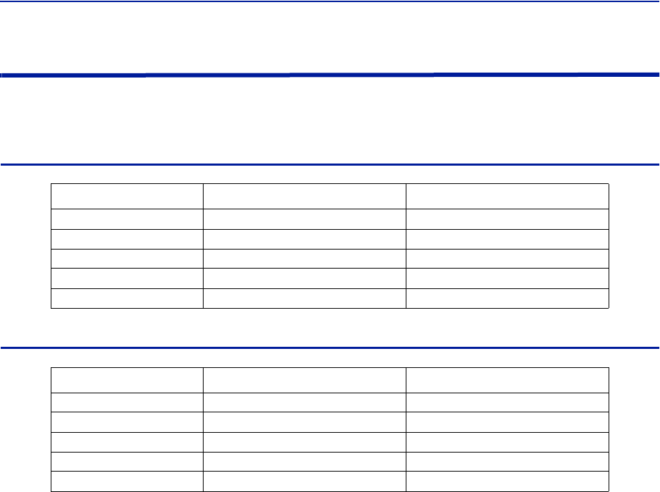
Part Number Frequency Band IC Certification Number
MOD‐DDR‐VVHF‐136‐174MHz 110141A‐DDR1V
MOD‐DDR‐UUHF‐450‐470MHz 110141A‐DDR1U
MOD‐DDR‐QT‐Band‐470‐512MHz 110141A‐DDR1Q
MOD‐DDR‐F700MhzPS 110141A‐DDR1F
MOD‐DDR‐S800MHzPS 110141A‐DDR1S
Cellular DDR Module Numbers
Part Number Frequency Band IC Certification Number
MOD‐DDR‐G700cellfullband 110141A‐DDR700FB
MOD‐DDR‐C850cellband 110141A‐DDR850
MOD‐DDR‐P1900PCS 110141A‐DDR1900
MOD‐DDR‐A2100AWS 110141A‐DDR2100
MOD‐DDR‐E2600 110141A‐DDR2600

FiberDistributedAntennaSystem(FiberDAS)
117