Deltanode Solutions DDS001 Distributed Antenna System User Manual
Deltanode Solutions AB Distributed Antenna System
User Manual
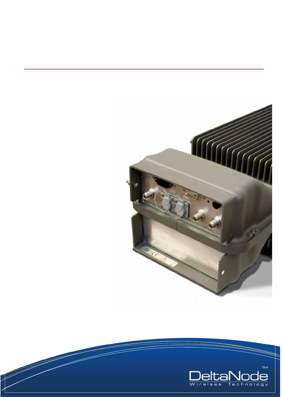
Release 15-01
Copyright © 2015 DeltaNode® Solutions Ltd. Sweden
DeltaNode Solutions
USER MANUAL

DELTANODE USER MANUAL
©DeltaNode Solutions 2015
1
Revision 15-01
Contents
1 Introduction..................................................................................................................................... 2
1.1 RF on fiber ............................................................................................................................... 2
2 Installation guidelines ..................................................................................................................... 3
2.1 Health and Safety .................................................................................................................... 3
2.2 Installing the Master Unit........................................................................................................ 4
2.3 Installing the Remote Units..................................................................................................... 5
3 System Description.......................................................................................................................... 8
3.1 Purpose.................................................................................................................................... 8
3.2 General .................................................................................................................................... 8
3.2.1 Specifications:.................................................................................................................. 8
3.3 Master Unit.............................................................................................................................. 9
3.3.1 MFU – Master Frame Unit............................................................................................... 9
3.3.2 BIU – The Base Station Interface................................................................................... 10
3.3.3 FOI – The Fiber Optic Interface unit .............................................................................. 10
3.4 Remote Unit .......................................................................................................................... 12

DELTANODE USER MANUAL
©DeltaNode Solutions 2015
2
Revision 15-01
Single mode fiber
Angled connectors
Optical loss < 15 dB
1 Introduction
This document contains quick guidelines on how to operate the DeltaNode Fiber-DAS concept and
how to install a Remote Unit on site, commission and maintain such a system for the life span of the
entire installation.
When other manufacturers have converted off-air repeaters into fiber-fed repeaters, DeltaNode has
developed the concept from scratch with fiber distribution in mind from the start. This allows for
extremely good radio performance and we are proud of having the best in class noise figure of less
than 3 dB for the whole system, antenna > remote unit > base station interface port.
1.1 RF on fiber
A fiber distributed antenna system (Fiber-DAS) is a very efficient way of transmitting radio signals
over large distances. Up to about 25 km of fiber between the head-end and the remote unit is
allowed, providing that the radio access technology (RAN) do not suffer timing issues and that the
fiber loss is within the specification.
The main principle is to use an infra-red light source which is modulated with the combined radio
signals that needs to be propagated. The fiber channel system is ultra wide-band, ranging from 88
MHz up to 2600 MHz and thus covering most types of radio communication systems such as FM
broadcast, VHF communication radios (so called PMR systems), TETRA, GSM, CDMA, WCDMA and
other radio access technologies that are available.
The dynamic of the fiber is good enough to tolerate multi-carrier, multi-band and multi-operator
solutions this way, but of course they all share the available dynamics and if there are a very large
number of carriers the fiber attenuation needs to be looked at of course.
Because most land mobile radio systems and cellular systems are using Frequency Division Duplex
(FDD) this means that there needs to be either two separate fibers, one for the uplink (signals from
the terminal towards the base station) and for the downlink (signals from the radio base station
towards the terminal) or they may be multiplexed on the same fiber using different wavelengths.
The most popular way is to use wave-length division multiplexing
(WDM) which is the normal configuration of the DeltaNode Fiber-DAS
concept. However, separate UL/DL fibers can be used if it is necessary
or desired.
Because the modulation is analogue the system requires the fibers to be of single mode type. All
connectors used in DeltaNode equipment for Fiber-DAS are of SC-APC type with a 7° angle. It is very
important that all connectors in patches et cetera between the Master Unit (MU) and the Remote
Unit (RU) are angled; otherwise reflections are caused which will cause problems with the quality of
the signals throughout the entire DAS system.
DELTANODE USER MANUAL
©DeltaNode Solutions 2015
3
Revision 15-01
2 Installation guidelines
2.1 Health and Safety
DeltaNode DAS system is an advanced system and should be handled by skilled staff. DeltaNode is
offering training of installation service providers in the case where this is necessary.
Read all available documentation and warnings before handling the equipment!Equipment
failures due to improper handling are normally not covered by the product warranty!
Respect all warning signs on the equipment and in the documentation. Make sure to only operate
the equipment on frequencies allowed to use. Do not modify the equipment! The equipment
contains a Class 3B laser and the equipment is Class 1. Never look into the Laser beam directly or
indirectly, it is strong invisible light and may cause serious damage to human eyes!
Always use protective hat on fiber and connector end when fiber is removed from socket! Always
clean socket and connector after a fiber has been removed before you re-attach it again!
Make sure to keep passwords and other operational information away from unauthorized
personnel!
•DeltaNode DAS system is an advanced system and should be handled by FCC Licensee or
FCC approved staff.
•Read all documentation and warnings before handling the equipment.
•Obey all warning signs on the equipment and in documentation
The equipment may get hot during operation, do not operate outside permitted
temperature range and keep away from heat sensitive material!
Always disconnect the unit before opening; opening is not intended to do in the field!
The equipment contains ESD sensitive components. Open the equipment ONLY in a safe
location designed for handling ESD products and use grounding devices!
The product transmits RF signals. Make sure to keep away from Antennas and other
radiating devices!
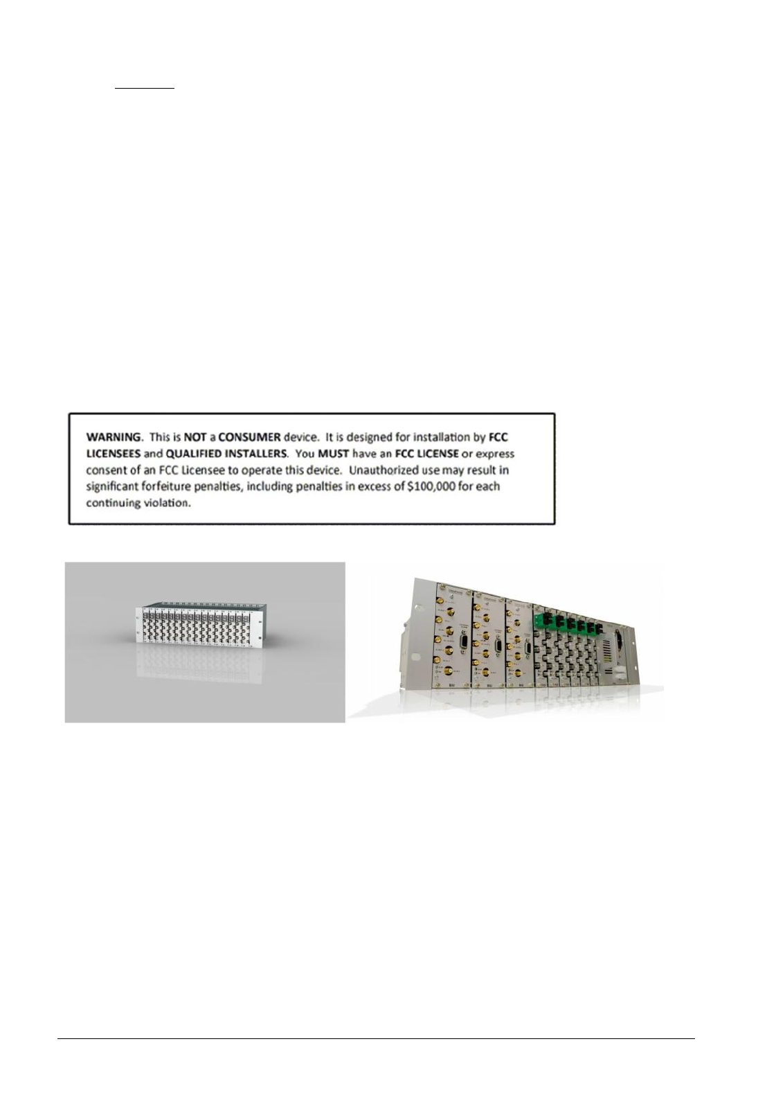
Avoid overheating by sunlight exposure!
If the RU may be exposed to strong direct sun, use sun protector plate provided by
DeltaNode! (see picture below)
Consult a FCC licensee or other applicable regulation body for details on RF requirements
and safety issues on RF!
DELTANODE USER MANUAL
©DeltaNode Solutions 2015
4
Revision 15-01
Warning!
It is NOT recommendable to use markets unknown manufacturers for the passive
components within the DAS. Before using the passive components, the datasheets of such
components should be revised closely by the responsible network provider and all link
budgeting calculations should be done accordingly.
2.2 Installing the Master Unit
All equipment must be properly grounded. This means that the ground peg in the mains connector
for both head-end gear (Master Unit) and remote gear (Remote Units) must be connected to Phase,
Neutral and Ground in a proper way before the plug is inserted in the unit.
The chassis of the remote and the rack of the master unit should be grounded to a potential bar or
safety grounding bar when operated. All electrical installations should be done by an FCC Licensee
or/and a certified electrician only!
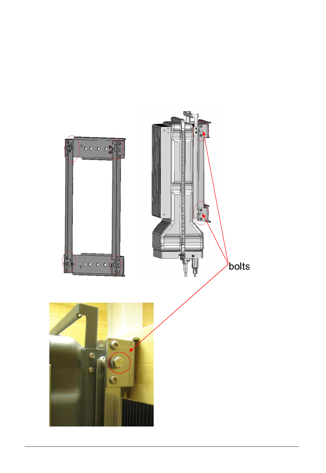
Figure1: Master Unit Frame (example1) Figure2: Master Unit Frame (example2)
Mount the BMU frames into cabinets
Mount ethernet switches and cables
Mount power cables (use P101 on the frames for primary power, P102 for secondary power)
Install BGW and connect cables
Insert all units
Start switches
Start BGW, wait for a few minutes until it comes up and log into it to start optimizing the
system
DELTANODE USER MANUAL
©DeltaNode Solutions 2015
5
Revision 15-01
2.3 Installing the Remote Units
The remote units have two different types of mounts.
1. The standard wall mounts. This mount is fixed to the wall with suitable bolts and then the
remote is just slided in and fixed with 4 screws (included) so it cannot escape the wall mount.
Snap in the complete single or dual chassis into the Wall bracket. Tighten the four bolts (two
on each side)
See Pictures Below!
Figure 2:Wall mount frame Figure 3: RU in the frame
Figure 4: Tightening Bolt of the frame
DELTANODE USER MANUAL
©DeltaNode Solutions 2015
6
Revision 15-01
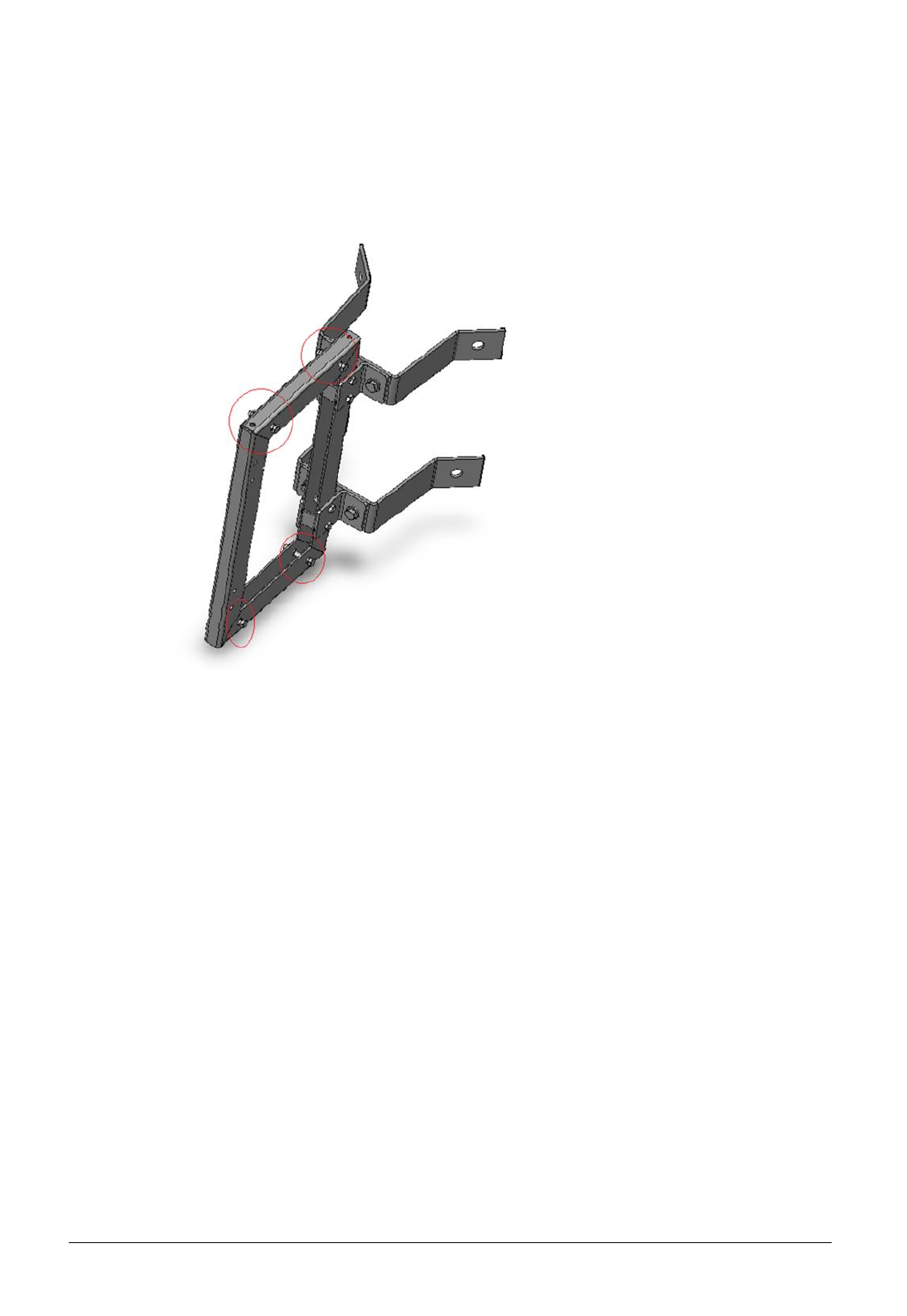
2. The pole mounts. The pole mount kit is an addition to the wall mount kit. They are first
assembled together, and then mounted on a pole after which the remote unit is slid in and
fixed with 4 screws (included), as seen in pictures above.
Figure 5: Pole mounting frame
DELTANODE USER MANUAL
©DeltaNode Solutions 2015
7
Revision 15-01
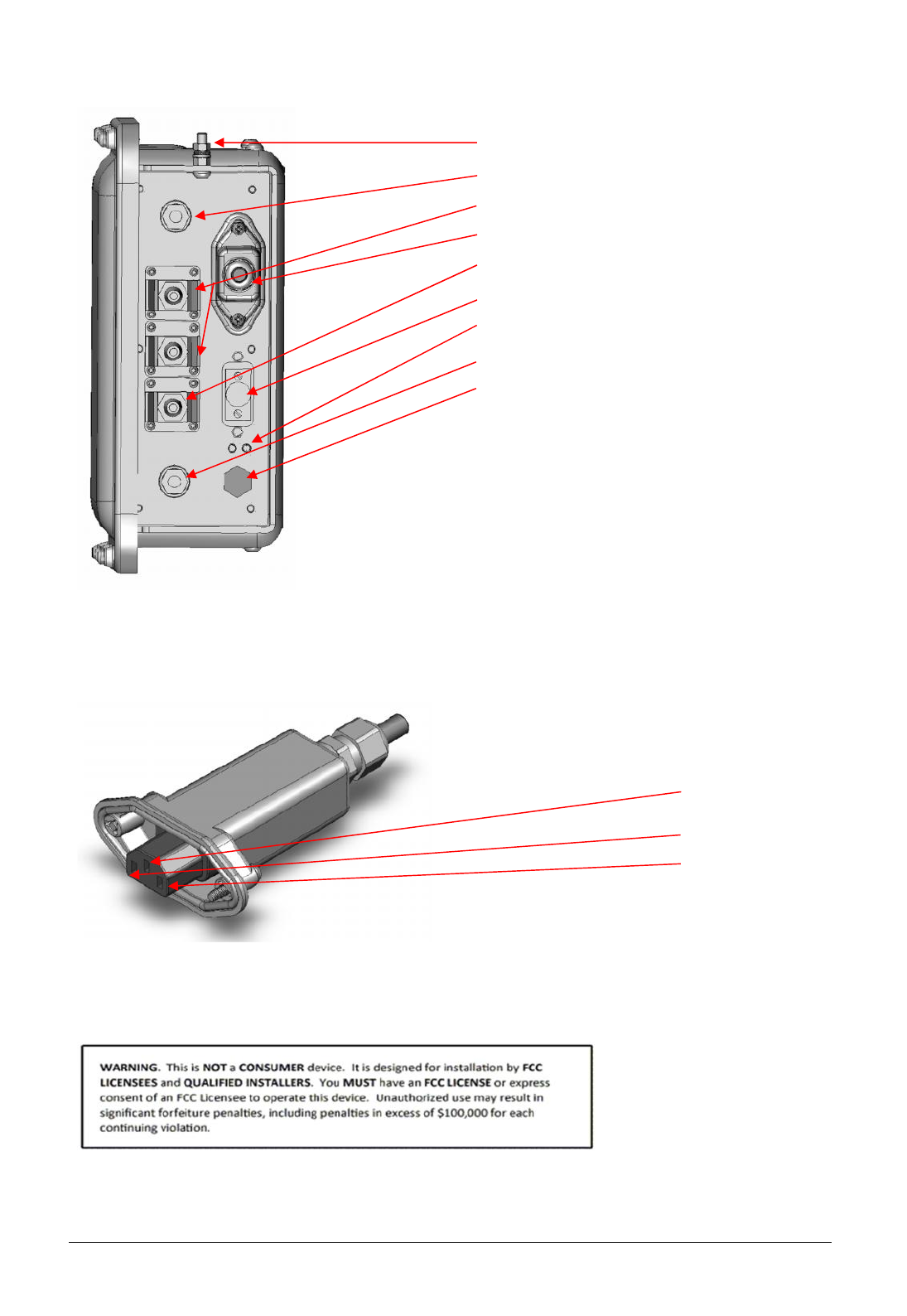
3. Connectors and connections of the RU are listed in the picture below.
Figure 6: Connector and connections on the Remote Unit
After this the fibers should be connected in the fiber optical port. This can either be done with
standard SC/APC fibers or a special heavy-duty SCRJ-cable for outdoor and rough environments (IP65
class). Antenna jumpers are connected to the N-type or DIN 7-16 connectors at the bottom, and
finally the power cord is connected using an IP65 protective housing (included, see picture below).
Figure 7: Mains Connector
When the power is connected the remote automatically turns on and will attempt to connect to the
master unit over the fiber.
All electrical installations should be done by an FCC Licensee or/and a certified electrician only!
After the successful mounting installation and powering the Remote units, user can now start
optimizing the DAS system and accessing the Remote units through the Base Station Gateway.
Login and access information such as username and passwords are provided separately.
Ground screw
Antenna connector, Type N
Optical connector 1 and 2
Mains Connector
Ethernet Connector
External alarm connector
LED status, green power, red fault
Antenna connector, Type N
Gore-Tex Breather
Ground
Phase
Zero

DELTANODE USER MANUAL
©DeltaNode Solutions 2015
8
Revision 15-01
3 System Description
3.1 Purpose
The DAS system is intended to distribute wireless services for voice and data over dedicated
fiber from Master units located at the BTS site hotels to small Remote units intended for
discrete mounting in an urban or suburban environment on poles or other outdoor
locations. The system is built on multiple wideband RF links both uplink and downlink
running on a separate fibers between the BTS site and Remote unit using multi drop for best
fiber usage and CWDM technology.
3.2 General
The system has either a common optical cable for its signal paths (uplink and downlink) or
separate optical cables, all units are equipped with remote control and the communication is
performed via a sub-carrier channel on each optical link. Every remote unit has a WEB
interface that is accessible from a standard PC with a WEB browser. In the master unit there
are low power TX and Rx RF cables connection from the various BTS’s to the optical interface
through some splitters. The system is managed by a CGW, Central Gateway that is the
overall interface point of the system for management function.
The CGW can interface to top level O&M systems, it has routing and firewall functionality
alarm log and access control for the complete DAS system. It has the function to
interconnect all control communication, monitor the modules in of the DAS system and send
alarms to a common point via Email and/or SMS.
3.2.1 Specifications:
Preliminary System Requirements
Optical link budget <15dB
Support CWDM/multicolor operation and multidrop.
Support wireless systems in the frequency range of 88-2200 MHz
Preliminary Specifications and Requirements – NOC/O&M Software
Web based
SNMP export capability (option)
Real Time Operation
IP based communication links
SMS export capability
E-mail export capability
DELTANODE USER MANUAL
©DeltaNode Solutions 2015
9
Revision 15-01
The Fiber-DAS system consists of two major parts; Master Unit and Remote Unit. The Master Unit
(MU) and one or more Remote Units (RU) are connected to each other using optical fiber link.
3.3 Master Unit
The Master Unit consists of a 19 inch frame rack with modules that are selected depending on the
system design. Generally all Master Units contains a power supply, at least one Base Station Interface
Unit (BIU), an RF splitter/combiner unit called the Point of Interconnect (POI) and minimum one
Fiber-Optic Interface card (FOI).
3.3.1 MFU – Master Frame Unit
The Master Frame Unit houses the other modules such as power supplies, fiber-optic interface cards
and base station interface units.
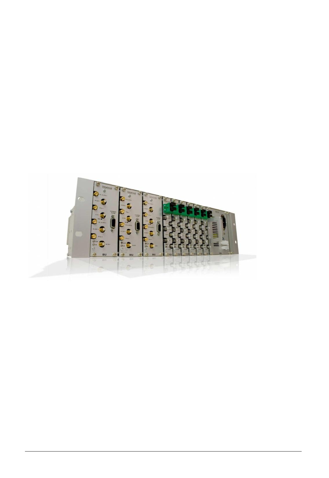
Figure 8: Master Unit
The frame in the picture shows a frame equipped with 3 base station interface units, 6 fiber-optic
interface cards and one power supply (as just an example).
Functional description
One frame supports several modules which can be placed anywhere in the frame as well as a
combination of several different types of units in a frame. There are 16U positions in the frame that
can be utilized. The modules have different widths which can be found in each module’s
specifications in the following sections of this manual.
This means that one shelf can house up to 4 power supplies or 8 base station interface cards or up to
16 fiber-optic interface cards. Each frame needs at least one power supply, but they do not
necessarily have to be placed in the frame that they power. Quite often a system has more than one
power supply and they are usually placed together in one frame for easy access.
Each frame has two Molex connectors that can be connected to a power supply. This allows for a
primary and a redundant power supply to be connected to it to ensure operation even if one power
supply should fail.
DELTANODE USER MANUAL
©DeltaNode Solutions 2015
10
Revision 15-01
The frame also contains fans used to ventilate the units housed in the frame. These are high quality
fans that have a high MTBF.
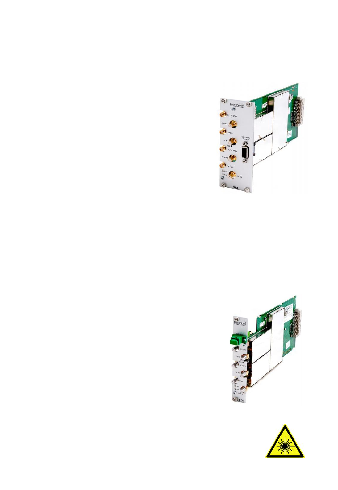
3.3.2 BIU – The Base Station Interface
The BIU is the interface used between the operator’s base station
and the Fiber-DAS system. This module has several RF connectors
on the front panel and it contains duplex filters (optional) or
separate uplink/downlink paths which can be chosen depending
on the needs for the connection to the base station. In most
cases the duplexed version with a combined DL/UL port is used.
Functional description
In the duplexed version there are UL test connectors present
(SMA) that can be used to monitor the signal out from the BIU.
The version without duplex filters has the test connectors
replaced by UL connectors and the normally combined DL/UL
connectors are replaced by DL only connectors.
LED behavior
The unit has two LEDs located on the front panel. One is the power on LED (green) and the other is
the alarm LED (red). Both LEDs can indicate a number of states by different flashing behaviors.
Using it as a splitter means you connect the combined signal to the COMMON port and you can then
receive 8 ports with equal signal strengths on ports 1-8 (minus insertion loss).
3.3.3 FOI – The Fiber Optic Interface unit
The FOI is the unit responsible for converting the RF signals in the
downlink to fiber-optical laser that can be transmitted over the fiber
link to the remote unit. It is also responsible for receiving the laser
light transmitted by the Remote Unit and convert it back to RF signals
that will then usually go into the POI and then later in to the BIU and
further to the Base Station.
The fiber-optic interface can either be a single fiber interface (with
WDM) or a dual head with separate Rx and Tx connectors. This is
ordered as needed when the Master Unit is specified.
Each FOI can serve up to 4 Remote Units over a single fiber.
Safety and Care for fibers
The laser is a Class 3b laser that produces invisible infra-red coherent light.
EXTREMELY IMPORTANT is to avoid looking into fiber connectors and receptacles.
Not safe to view with optical instruments. Always use the protection caps on not
used fibers and receptacles.
Figure 2: Fiber optic interface
Figure 1: Base station interface
DELTANODE USER MANUAL
©DeltaNode Solutions 2015
11
Revision 15-01
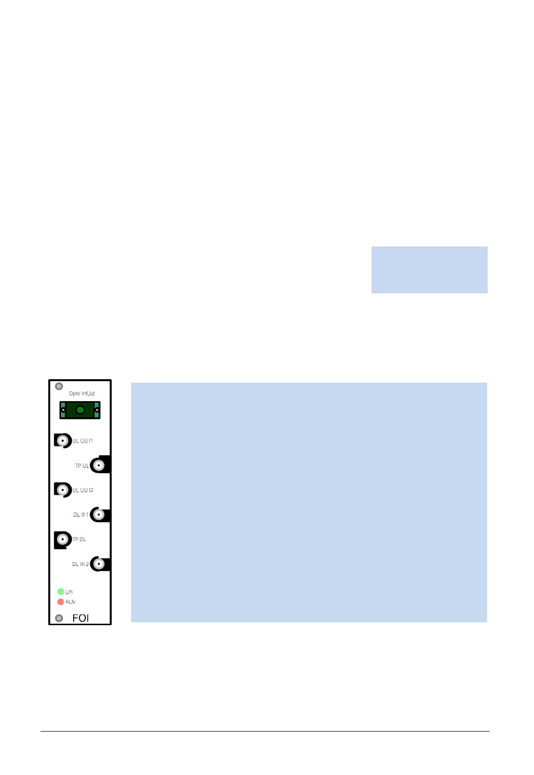
OPTO IN/OUT
This is the receptacle for the optical fiber. The illustration shows the module
with built in WDM (combined Rx/Tx).
UL OUT 1/2
These are the RF ports that normally are patched to the POI for
interconnecting and then further on to the BIU.
DL IN 1/2
These are the RF ports where the signal in the DL from the POI is patched into
the FOI for conversion to laser light and further to the RU.
TP UL/DL
These are test ports that can be used to check the signal levels or noise in the
DAS- system.
Single mode fiber
Angled connectors
Optical loss < 15 dBo
Every time a fiber is disconnected and re-connected care should be taken to avoid dust to settle on
the connector or in the receptacle. Clean with a dry fiber cleaning tool before reconnecting the fiber
at all times. A single speck of dust can impact the transmission severely. Do not touch the fiber ends
with your fingers. That will leave grease on the connectors and may cause severe problems.
Functional description
The output power of the laser is calibrated and tuned to 3 000 µW.
The FOI is powered from the rack backplane and communicates with Ethernet with the other
modules in the Master Unit.
The unit contains adjustable attenuators.
This interface is designed to work with SC-APC connectors (7° angled
physical connector) and single mode fibers only. All connectors between
the master unit and the remote unit should be of angled type, otherwise
problems with reflections will arise which may cause severe problems in
the DAS- system.
Ports of the FOI
There are also two LED´s on the unit which can be used for visual check of the current status of the
FOI. Green led for operation status and the red one for current alarm status.
DELTANODE USER MANUAL
©DeltaNode Solutions 2015
12
Revision 15-01
3.4 Remote Unit
There are many different kinds of remote units with a wide range of gain and output power to cater
to many different needs. A low and medium power unit can house up to 4 different frequency bands
in one unit, the high power versions can handle up to 2 different bands in one single unit.
Chassis types
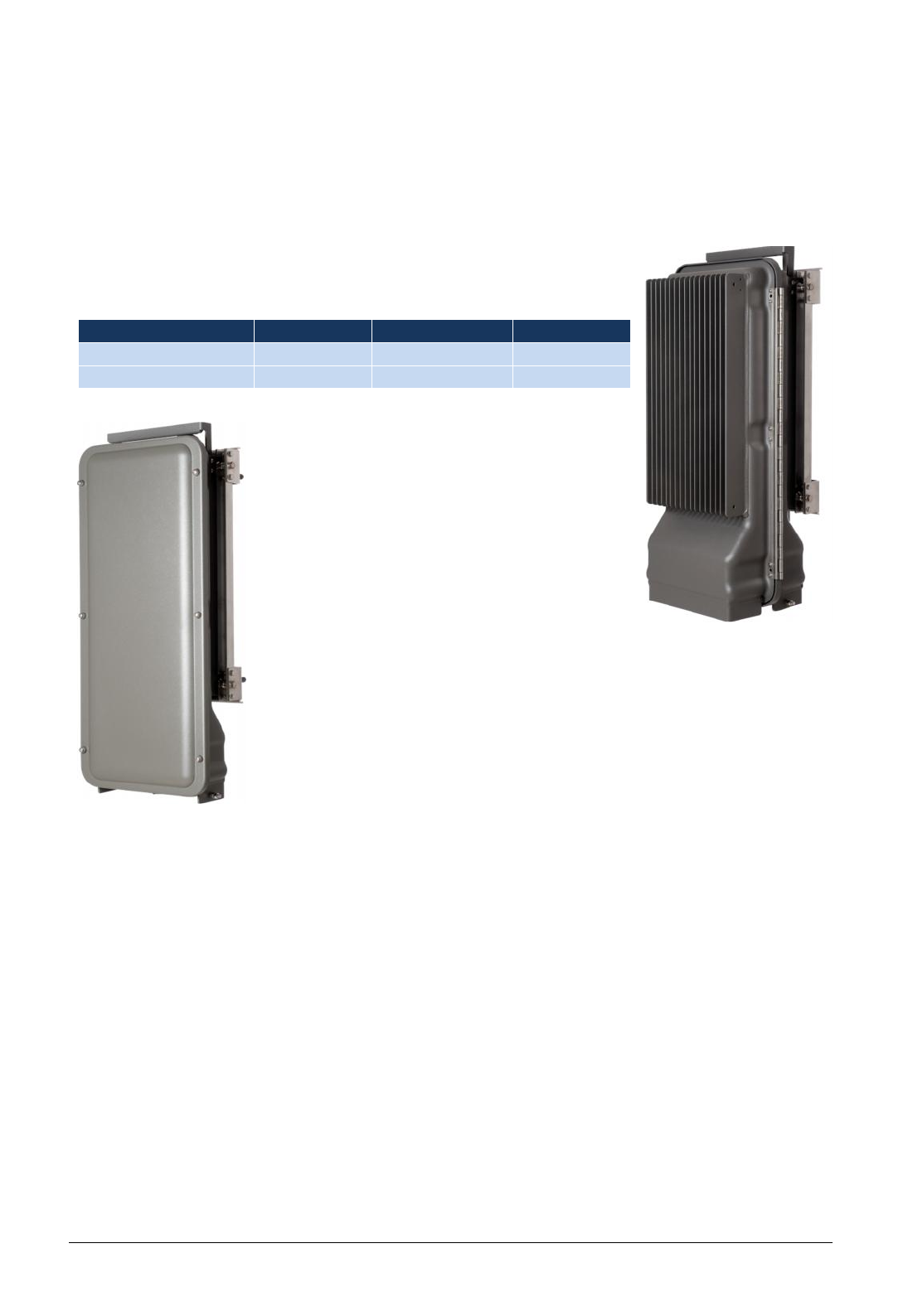
RUs comes in mainly two different chassis, a single compact chassis for 1-2
bands and a dual chassis for up to 4 bands. This is how they can be
configured:
Chassis type
Low
Medium
High
Single chassis
1-2
1-2
1-2
Dual chassis
3-4
3-4
3-4
Table 1: Chassis types
It is also possible to have combinations of the
above. For example it is possible to build a dual
chassis with 2 medium power bands and 1 high
power band in the same remote. Each side of a
dual chassis is virtually identical to a single chassis
remote unit. This ensures unparalleled flexibility
when building multiple operator / multiple band
solutions.
A dual chassis may have 1-2 optical remote units
(FOR). This way they can be fed from different
directions for redundancy.
Remotes can also be daisy-chained by way of RF cables, meaning up to two
chassis can share the same fiber-optical interface providing up to 8 bands in a
single location. Variants are available upon request.
Commonly for all Remote Units is their excellent noise figure, contributing to
an overall noise figure for the whole system from remote to head-end into
the base station of < 3 dB for the RF link.
Both chassis complies with IP65 protection for use in any environment. The coating is a durable
coating which eases the convection cooling. No fans are used for the DeltaNode Remote Units. Both
chassis are available both with wall and pole mounting kits as requested.
External Antenna´s that are most commonly used in combination with DDS Remote Unit family for
outdoor environment are 17 dBi gain antennas. Antenna used for MPE radiation calculation is a 17
dBi antenna.
Most commonly used manufacturers antennas in combination with DeltaNode DAS systems to our
knowledge are Cellmax, Kathrein and Amphenol antennas, and we believe that these manufacturers
holds best RF quality and performance.
Figure 4: Single chassis remote
Figure 3: Dual chassis remote

DELTANODE USER MANUAL
©DeltaNode Solutions 2015
13
Revision 15-01