Denon AVR 1082 User Manual RECEIVER Manuals And Guides L0211055
DENON Receivers Manual L0211055 DENON Receivers Owner's Manual, DENON Receivers installation guides
User Manual: Denon AVR-1082 AVR-1082 DENON RECEIVER - Manuals and Guides View the owners manual for your DENON RECEIVER #AVR1082. Home:Electronics Parts:Denon Parts:Denon RECEIVER Manual
Open the PDF directly: View PDF ![]() .
.
Page Count: 82

AV SURROUND RECEIVER
AVR-3802
OPERATING INSTRUCTIONS
BEDIENUNGSANLEITUNG
MODE D'EMPLOI
ISTRUZIONI PER L'USO
INSTRUCCIONES DE OPERACION
GEBRUIKSAANWIJZING
BRUKSANVISNING
J
_ _ _ 8 ,_¸
©
©
FOR ENGLISH READERS PAGE 2 - PAGE 42
FOR DEUTSCHE LESER SEITE 43 - SEITE 82
POUR LES LEGTEURS FRANCAIS PAGE 83 - PAGE I22
PER IL LETTORE ITALIANO PAGINA 123. PAGINA 162
PARA LECT©BES D£ ESPANOL PAG_NA IG3 P/IG_NA 202
VOOR NEDERLANDSTALIGE LEZERS PAGINA 203. PAGINA 242
FOR SVENSKA L/\SARE SIDA 243 . SIDA 282
,_ RISK OF ELECTRIC SHOCK A
DO NOT OPEN
CAUTION: TO REDUCE THE RISK OF ELECTRIC SHOCK, DO
NOT REMOVE COVER (OR BACK). NO USER
SERVICEABLE PARTS INSIDE. REFER SERVICING
TO QUALIFIED SERVICE PERSONNEL.
The lightning flash with arrowhead symbol, within an equilateral triangle,
is intended to alert the user to the presence of uninsulated "dangerous
volLage" within the product's enclosure that may be of sufficient
magnitude to const tute a risk of electric shock to persons
The excEamation point within an equilateraE triangle is ntended to alert the
user to the presence of important operating and maintenance {servicing)
instructions in the literature accompanying the appJiance
WARNING: TO REDUCE THE RISK OF FIRE OR ELECTRIC SHOCK, DO
NOT EXPOSE THIS APPLIANCE TO RAIN OR MOISTURE.
•DECLARATION OF CONFORMITY
We declare under our sole respoTlsibility that this
product, to who1 this declarat on relates, is in conformity
with the following sCandards
EN60065, EN55013, EN55020, EN6100032 and
£N61000_ 3
Following the provisions of 73/23/EEC, 89/336/EEC alld
93/68/E EC Directive
• 0BEREINSTIMMUNGSERKL._RUNG
Wr ek_er/ unte u_see Vera_tvvortung daf_ d[eses
Produkt, auf das sich dese Erkl_rur/g bezieht, den
lolger/deT1 Standards el/tspr;c It:
EN60065, EN55013, EN55020, EN6100032 und
EN610OO@_
Entsplicht den Verordllu/gen de Drektive 73/23/EEC,
89f336/EEC und 93/68/EEC
• DECLARATION DE CONFORMITE
Nous d_clarons sous notre seue esponsablit@ que
lappare[I, auquel se r_f@re cette d_claration, est
confom_e aux standards suivants;
EN60065, EN55013, ENS5020 EN61000 3 2 et
EN61000_ 3
Dapr¢s les dspositJons de la Diective 73/23/EE6,
89/336/EEC et 93/68/E EC
•DICHIARAZIONE DI CONFORMITA
D[chiai[ar,lo COT1 pena respoTlsab;It_ one questo
prodotto, al quale la nosra diC!liarazione si riferisce, @
oor/fom_@ alle segueT_t; _/ormat[ve
EN60065, EN55013, EN55020, EN61000 3 2 e EN61000
38
n collformita con le cond z oni delle d retCive 73/23/EEC,
89/'336/E EC e 93/68/EEC
QUESTO PRQDQTTO E' CONFORME
AL DM 28/08/95 N _8
•DECLARACI(SN DE CONFORMIDAD
Deca amos bajo nuestra exclusiva respolssabildad que
este p¢oducto al que hace referencia esca declaraci6n,
est_ conforme cot1 los siguieTstes est_sdares
EN60065, EN55013, EN55020, EN6 000_ 2 y EN61000
38
Siguiendo las provisiones de las Drectivas 73/23/EEC,
89/'336/E EC y 93/68/E EC
•EENVORMIGHEIDSVERKLARING
Wi verk_a en uits_utend op onze verantwoordelijkhek_
dat dt produkt, waarop deze verklaring betrekking heeft,
i/overeen_emmmg is met de volge/de normen:
EN60065, EN55013, EN55020, EN6100032 er/
EN61000@ 3
VolgeTls de bepalingen van de Richtline/ 73/23/EEC,
89f336/E EC en 93/68/EEC
•OVERENSSTAMMELSESINTYG
H_rmed intygas het p_ eget ansva art der/na produkt,
vilken detta intyg avser, uppfy_e f_larlde s allda der
Enligt stadga na idrektiv _3/23/EEC 8g/336/EEC oah
93/6_EEC
NOTE ON USE !HINWEISE ZUM GEBRAUCH /
OBSERVATIONS RELATIVES A L'UTILISATION /NOTE SULL'USO
NOTAS SOBRE EL USO /ALVORENS TE GEBRUlKEN /OBSERVERA
•A_id high tempe_ures
Allow for sdficient heat d}sperston when
i_stalled on a rack
• Vermeiden S_e hohe Teml_eraturel_
Beachten S_e dab e_r_e ausreichend
Lu_tz_rkulat}on gew_hlle_ste_ wird _n das
Ger;,t auf ein Rega_ gest eil_ w_rd
• Evite_ des temp@atures _lev_es
T_ cornice duroc dispersior_ de chaleur
suffisante lois de I_r_stal_atio_ sul une
_ta9ere
• Evitat e di espo_re I unit_ a tempelat ule a_te
Assicu_atevi cbe ci sia unadeguata
dispelslone del cajole quando h_sta_ate
I unit_ ir_u_ mob_;e per compone_ti audio
• Evite altas tempera_u_as
Permi_e _a su_ciente d_spersiCn del ca_or
cuando e_4 insta_ado er_ la _onsola
• Vermijd hoge temDer_,_u_en
Zorg voor eer_ degelijk h_ttea fvoer indien her
apparaat op een r_k woldt gep_aatst
• Undvik hoga temperatu=er
Se 1i_1 art de_ firms m_il_ghe_ fill god
v_meavledi/iag rid mon_eling i ett lack
• Ha_dle the powel cord calefuily
Ho_d the p_ug when ur_pkJg9i_g the co_
• Gehen Si_ valsichfig mit dem Netzkabe_ am
HaSten S_e das Kabe; am S_ReI_ wenr_ S_e
der_ St ecl<er he_ausziehen
T_rfir [a pdse lots du deb_ar_chement du
coldon
• Ma_neggiate i_ _ilo di a_r_er_tazione cor_ cura
Agite per b spina quando sco_legate il caw
•rvla_eje el _rdOr_ de energ_ cor_ cuk_ado
Sosten9a el e_chufe cua_do desk-creese el
• Hameer her ne_snoer voorzichfig
Houd _e_ snoer b}i de stekker wst wagoneer
deze mae_ walden aar_ of _asgekoppeid
• Keep the set _ee from mois_ule wate_ and
dust
• Halten Sic das Ge_t vor_ Feuchtigkeit
VVasse_ und Staub fen/
•pr_ger lappalei_ _r_tle I humk_it_ leau et
_apoussi_r_
•T_nete _ul_i_ Iontana da_umidit_ dallacqu_,
e dalla polve_e
• Mantenga el equipo _ible de humedad agua
y polvo
• Laa_ geen vochtighe_d water _ stof in her
appaTaat birmenddngen
• Uts4tt in_e apparate_ _or _ukt w4ten och
damm
• Unplug t_e power co_d when not usin 9 _he
set _or Ior_g pel_ods _ time
• Wer_n das Ger_t e_ne _ngere Ze}t r_cht
velwendet werden soil, trermen Sie das
Netzb,bel vom Net_stecker_
_appa_e_l n_est pas utilis_ pendar_ de
_ongues p_r_odes
• Dis_nnestate il fl;a di dimen_az_one qua_do
a_iment_,zior_e pel ua lu_go periodo d_ tempo
• Desc_nec_e e_ cor_r_ de er_e_gia cu_maa no
utilice el equipo pot mucl_o t}empo
• Neem a_tiid he_ r_etsr_oel ui_ her stopRon_akt
_r_aeer her ap_a_a_,t gedu=er_de een _a_ge
per_ode rfiet _rd_ 9ebr u_kt
(Fo_ se_s w_th ventilation holes)
• Do no_ obstru_ the ver_tilation holes
•Die Be_ftur9so_rul_gen drfer rficht
veldeckt 6,elden
• Ne p,_S obstl_er les trous d a@_, io i
• Non _up ire i _o_i di Yen _azione
• No obst r uya los orificios de Yen i ci6_
• De ver tilatieoper_nger r_ogen riet 6,Olden
beMokkee_d
• Tdpp irte till ver ti atior s6ppn ig, r/a
• Do not let _oreign objects in t_/e set
• Ke}ne fremden Ge9enst_de i_ das Ger_t
I(ommen lasser_
• Ne pas laisser des obje_s _tra_geTs darts
I appareil
• E ¸ impolt an_e the r_essun _ge_o _ iasefito
all intemcs dell urfit_
• No deie obje_os extra_os dentro del eq u_r_
• Laat gee_ vreemde voo_werpen m dit
apparaat vallen
• Se 1ill art fr_mma nde f_rem_l _nte tr_nge_ u_ _
appara_en
• Do not le_ _sectk:}des benzer_e and tl_ir_el
come in cor_tac_ w_t_/_he set
• L_,ssen S_e das Ger_t nk:ht mk Insektizk_en_
Ber_z}n oder Veld_,nl_ungsmit t elr_ u_
Bel _hl u_/g kommen
• Ne pas me_re en cont_,ct des _nsecti@des_
• Ass_cura_evvi che runit£ non ve_ga ir_
cor_tatto con inset ficid_ benzolo o so_venu
• No perm_ta el comacto de msecticidas_
gaso_ina ¥ d_iuyen_es cor_ el eqaipo
• La_,t geen _nsektenve_lelgende midde_en_
benz_ne _ ver_veTdu_ner met dit appa_aat in
kor_tald komen
• Se tii_ art inte insektsmedel p_ s_:_ybruk_
bensen och _hinner komme_ _ _on_a_t reed
apparmens h61je
• Never disasse_t_e ol modify the set _n any
• Ve_sucher_ S_e niema_s eas G_r_,_
ausei_ander zu nel_r_er_ ode_ au_ ieglicl_e Art
_u ver_dem
• Ne iama_s d_monter ou modifier rappa_e_!
d_une mani_re ou d_u_e autre
• Nor_ smor_tme mai_ n_ mod_ficate R_nit_ in
nessun modo
• Nut,ca desa_me o mod_fique el equ_r_ de
nlr_guna manera
• Nooit di_ apparaat demon_elen of op andere
wijze modifieren
• Ts inte is_r app_rate_ och _@s_k i_te bygg_
om aen
2
•We greatly appreciate your purchase of the AVR-3802,
•To be sure you take maximum advantage of all the features the AVR-3802 has to offer, read these
instructions carefully and use the set properly Be sure to keep this manuai for future reference,
should any questions or problems arise
"SERIAL NO
PLEASE RECORD UNIT SERIAL NUMBER ATTACHED TO THE REAR OF THE
CABINET FOR FUTURE REFERENCE"
•INTRODUCTION
Thank you for choosing the DENON AVR-3802 DigitaE Surround A /V receiveE This remarkable component has
been engineered to provide superb surround sound listening with home theater sources such as DVD, as welE as
providing outstanding high fidelity reproduction of your favorite music sources
As this product is provided with an immense array of features, we recommend that before you begin hookup and
operation that ' ou review the contents of this manual before proceeding
TABLE OF CONTENTS
h_] Before Using ........................................................ 3
_] Cautions on InstaElation ........................................ 3
J_] Cautions on Handling ........................................... 3
J4] Features ............................................................... 4
I_] Connections ..................................................... 4-8
I_] Part Names and Functions .............................. 8, 9
[7_] Setting up the system ................................... 9-16
18] Remote Control Unit ................................... 16-22
[91 Operat on ..................................................... 22-26
I10]Surround......................................................27-29
1L_ DSPSurround Simulation ............................30-32
J_ Listening to the Radio.................................33-35
J_ Last Function Memory .......................................36
J_ InitiaEizationof the Microprocessor ....................36
J_ Troubleshooting...........................................36, 37
Additional Information .................................37-41
Specifications.....................................................42
•ACCESSORIES
Checkthat the following parts are included in addition to the main unit:
[] BEFORE USING
Pay attention to the following before using this
unit:
•Moving the set
Tu prevent shor_ circuits or damaged wires n the
connection cords, always unplug the power cord
and disconnect the connection cords between all
other audio components when moving the set
•Before turning the power switch on
Check once again that aEI connections are proper
and that there are not probleE'qs with the connection
cords¸ Always set the power switch to the standby
position before connecting and disconnecting
connection cords¸
•Store this instructions in asafe place.
After reading, store this nstructions aEong with the
warranty in a safe place
•Note that the illustrations in this instructions
may differ from the actual set for explanation
purposes.
[] CAUTIONS ON INSTALLATION
Noise or disturba_lce of the picture may be generated
if this unit or any other electronic equipment using
microprocessors is used near a tuner or TV
If this happens, take the following steps:
• Install this unit as far as possible from the tuner or
TV
• Set tile antenna wires from the tuner or TV away
from this unit's power cord and input/output
connection cords
• Noise or disturbance tends to occur particularly
when using indoor antennas or 300 _Z/uhms feeder
wEres We recommend using outdoor antennas
and 75 £_/ohms coaxial cables.
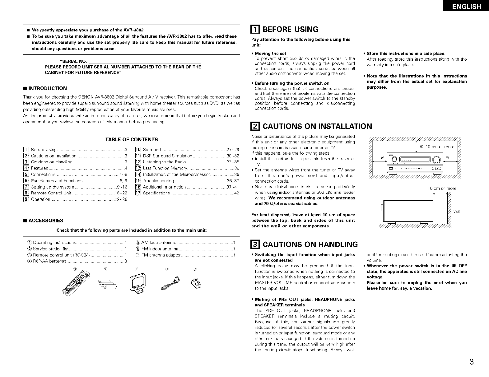
For heat dispersal, leave at least 10 cm of space
between the top, back and sides of this unit
and the wall or other components.
_g cm or more
wall
,_1}Operating instructions ........................................ 1
Service station list .............................................. 1
Remote control unit {RC-884) ............................ 1
R6P/AA batteries ................................................ 3
_5 AM loop antenna ................................................ 1
FM indoor antenna ............................................. 1
FM antenna adaptor ........................................... 1
[] CAUTIONS ON HANDLING
•Switching the input function when input jacks
are not connected
A clicking noise may be produced f the input
function is switched when _lOthi_lg is con_lected to
the input jacks If this happens r either turn do_vn the
MASTER VOLUME CO_ltrOlor connect compo_lents
to the input }acks
•Muting of PRE OUT jacks, HEADPHONE jacks
and SPEAKER terminals
The PRE OUT jacks, HEADPHONE iacks and
SPEAKER termnals include a mutng crcuit
Because of this, the output signals are greatly
reduced for several seconds after the power switch
is turned on or i_lput function, surround mode or any
other-set-up is changed If the volume is turned up
during this time, the output will be very high after
the muting circuit stops functioning Always wait
until the muting circuit turns off before adjusting the
volume
•Whenever the power switch is in the IL OFF
state, the apparatus is still connected on AC line
voltage.
Please be sure to unplug the cord when you
leave home for, say, a vacation.
3

l_Ee]!!_l]]
[] FEATURES
1. Digital Surround Sound Decoding
Featuring 32 bit high speed DSP, operating entirely
in digital domain, surround sound from digital
sources such as DVD, LD, DTV and satellite are
faithfully re-created
2. Doiby Pro Logic I! decoder
Dolby Pro Logic II is a new format for playing
multichannel audio signals that offers
improvements over conventional Dolby Pro Logic¸
It can be used to decode not only sources
recorded in Dolby Surround but also regular stereo
sources into five channels (front left/right, center
and surround left/right) In addition, various
parameters can be set according to the type of
source and the contents, so you can adiust the
sound field with greater precision¸
3. Dolby Digital
Using advanced digital processing algorithms,
Dolby Digital provides up to 51 channels of wide_
range, high fidelity surround sound¸ Dolby Digital
is the default digital audio delivery system for
North American DVD and DTV
4. DTS (Digital Theater Systems)
DTS provides up to 51 channels of wide-range,
high fidelity surround sound, from sources such as
laseE disc, DVD and specially_encoded music
discs¸
5. DTS-ES Extended Surround and DTS Neo:6
The AVR_802 is compatible with DTS_ES Extended
Surround, a new multFchannel format developed by
Digital Theater Systems Inc
The AVR-3802 is also compatible with DTS Neo:6, a
surround mode allowing 61-channel playback of
regular stereo sources
6. Wide screen mode for a ?.l-channel sound
even with
5.1-channel sources
DENON has developed a wide screen mode with
a new design which recreates the effects of the
multi surround speakers in movie theaters¸ The
result is 71 _channel sound taking full advantage of
surround back speakers, even with Dolby Pro
Logic or Dolby Digital/DTS 5 l_channel signals¸
?. 24 bit D/A Conversion
All six channels, including the five main channels
and the low frequency effects (LFE) channel
benefit from reference, for optimum high fidelity
reproduction of music and movie soundtracks
8. Dual Surround Speaker Mode
Provides for the first time the ability to optimize
surround sound reproduction using two different
types of surround sound speakers as well as two
different surround speaker positions:
4
(1) Movie Surround
Motion picture soundtracks use the surround
channel{sl to provide the ambient elements of
the acoustic environment they want the
audience to realize This is best accomplished
by the use of specially-designed surround
speakers that offeE a wide diffusion pattem
(bipolar dispersion) or by using surround
speakers that provide broad dispers on with a
mmEmum of on-axis localization (dipolar
dispersion) Side wall mounting (closer to the
ceiling) of the surround speakers provides the
greatest envelopment, minimizing Iocalizat on
of drect sound from the speakers
(2) Music Surround
With full range discrete surround cpannels, as
well as three discrete full range front channels,
digtal formats such as Do]by and DTS offer
thrilling surround sound music listening
Producers of mulLFchannel discrete dgital
music recordings almost always favor the use
of direct radiating (monopolar) surround
speakersr placed in the rear corners of the
room, snce that is how they configure their
studios during the mixing/creation process
The DENON AVR-3802 provides the ability to
connect two different sets of surround
speakers, and place them in the appropriate
locations in your AV theater room, so that you
can enjoy both movie soundtracks and music
listening, with optimum results and no
compromise
9. Component Video Switching
In addilion to composite video and "S r' video
swtching, the AVR_3802 provides 2 sets of
component video (Y, PB/C8, PR/CR) inputs for the
DVD and TV/DBS inputs, and one set of
component video outputs to the television, for
superior picture quality
10. Video Select Function
Allow you to watch one source (visual) while
listening to another source (audio)
11. Future Sound Format Upgrade Capability via
Eight ChanneI Inputs & Outputs
For future multi-chan_el audio format{sl, the AVR_
3802 is provided with 71 cham_el {seven main
channels, plus one low frequency effects channel)
inputs, along with a full set of 71 channel pre-amp
outpUtSr controlled by the 8 channel master
volume control This assures future upgrade
possibilites for any future mult-channel sound
format
[] CONNECTIONS
• Do not plug in the AC cord until all connections
have been completed
• Be sure to connect the left and right channels
properly (left with left, right with right)
• Insert the plugs securely Incomplete connect ons
win result in the generation of noise
•Use the AC OUTLET for audio equipment only,
Do not use them for hair driers, etc.
• Note that binding pin plug cords together with AC
cords or placing them near a power transformer
will result in generating hum or other noise
• Noise or humming may be generated if a
connected audio equipment is used independently
without turning the power of this unit on If this
happens, turn on the power of the this unit
• When making connections, also refer to the operating instructions of the other components
The power to this outlet is turned on and off when the power is switched between on and standby from the
remote control unit or power switch
LFConnecting the AC OUTLET jq
ulu CD playe_ AC OUTLET
total c ll2_cit V1()0/^])
o _ o /or lec_ fie (D paye_s The _owe o fls oltlet is _t_med Oll and of h, con u,ct o1_ ¢_th he
,, i_1o olip Jr lacks PO/^]E_ ?p_[_, o1_ swit¢[ o[ t[_ ila/ tJflt 811d when ihe powe_ is
(ANALO(_ OL TPUT) o t[is s_'dtched beb_veel, or asld star dby _rol_ le le _ote cortlo ulit
I Co_l_e_ing at_r _able I
Cor_nect the turntable s output cord to the
AVR 3802s PHONO acks tie L{et) plug to
/e L },ok the R ight) hg to tie r}gl_ lack
NOTES:
• This urfit csnno[ be used
ca_tlk_ges d_rectly Use a separate head
a_npli_er o_ ste_ UD _ransfo_mel
• If _/ul_r_i_g or othel no_se _s genel_ted
unit% CD jacks using pin
plug COlds
No I)OWel is supp_ed _rom this outlet wher_ this ul_it s _ower is at
stand_ Never c_l_ect equ_pl_ent whose to_al c_padty _s a_ve /O0
W
NOTE:
Only use the AC OUTLET fol audio equipment Nevel use them fol
bah dr_els_ TVs ol ofi_e_ e_e_ical appliances
MD reco_de_; CD leccrder cr other componen_
equipped with digital inpuVuu_pu_ lacks
etc ir_
a w_y that they do not
EPow_ s_ppl¥ co_d_
AC 2_0V 50Hz
CD p_ayer ol ot_/er component equipped
wi_h d_git_ output iacks
IConnectin_l the DIGITAL jacks]
Use these fol connections _o audio equipmer_t wifl_ d_git_l output Refer to
page 14 fol ins_r ucfions on setting fi_is tem_nal
NOTES:
• Use 75 _Vohms cable pin cords _or coaxial connections
• Use optical cables for optical conn_cfions_ removing fi_e cap before
conr_cfing
_p_,_L_,_ _ : :: : @ byatapedeck,etc_moveti_e
• • _apedeckaw,ay
i Connectin_lataped_cki
Connectionsfor recording:
Connectthetapedeckslecold_ng_nputjacks{L_NE_No_REC}to _h_sunit%
_apelecolding(CDR_APEOUT)}acksusingpinp_ugCOlds
Connectionsfor playback:
Cormectthet_pedeemsp_aybackoutputj_cks(L_NEOUTo_PB}to th_s
uniFs_apeplayback{CDR/TAPEIN)iacksusin9 p_np_ugcords
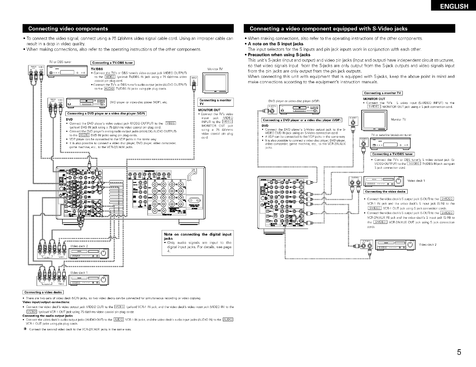
•TuconnectthevideosignaE,connectusinga75_/uhmsvideosignaEcablecordUsinganmpropercablecan
resultinadropinvideoquality
•Whenmakingconnections,alsorefertotheoperatnginstructionsoftheothercomponents
l_' or DBS turner I Connecting a TVIDBS tuner I
,,oLio _ TV/DBS Monitor ]%'
to !ile _ Iye_Fow} _f/DBS IN iaek usin 9 a 75 ldohms video
coaxial pin plug co_d
• (_onl_ect _he TVs ol DBS tuners _dio output jacks (AUDIO OUTPUT}
to 1he _ _,_f_B S IN jacks using pir_ plug colds
v,o[o D _== I
i
I
f V I C°nne_tingeDVOplayer°ravid_i_pl_yeriVDP) l
DVD
• Con lect tile DVD pl '/e_ s vide) o lip it ac£ (VID_ O OUTPUT) to tie
(yel ow) DV r} IN ),,ck esng a 75 [do ii_ s vdeo {u x]aJ pit pug _%)r(}
• Con lect the DVD payel s ar alog audio output jacks ANALOG AJDIO OUTPUT)
to tie _ DVD IN jacks usilg pit plug COldS
• VDP pla/,e can be co/nect ed o the VDP jacks in tile sa _e way
• It is aso possible 1o {urne a w_eo dsc player DVD player video car icorde_
ga _e rlacl ne ec to tile VCR 2/_/AUX jacks
22222222292
Vide? deck 2
ITVC°nne_ting a mo_li_or I
MONITOR OUT
• Connect _he _'s video
input jack !VIDEO
INPUT_ _o _he _
MONITOR OUT iack
usi_g a 7_ _/oi/ms
vid_ e_xi_l pir_ p_ug
cord
.¢,®®,®_
-@@®'@ @'@'/
Note on connoting the digi_l input
JtCC_SlV audio signal .... input to tile
digita nput jacks For detals, £ee page
• When making connections, also refer to the operating instructions of the other components
•A note on the S input jacks
The i_]put selectors for the S inputs and pin jack i_]puts work i_] conjunction with each other
•Precaution when using S-jacks
This u_]it's S-iacks (input and output) and video pin jacks {input and output) have i_]depe_]dent circuit structures,
so that video signals input from the S-jacks are only output from the Slack outputs and video signals input
from the pin jacks are only output from the pin jack outputs
When connecting this unit with equipment that is equipped with Slacks, keep the above point in mind and
make connect ons according to the equipment's instruction manuals
DVD plave_ or v_deo disc pl_ye_ _VDP!
Connecting a DVD player or a video disc player (VDP) I
DVD
• Connect _he DVD players S V_deo output i_ck to the S
VIDEO DVD _N jack _lsing a_ S Video connectior_ cord
• A VDP can be cormected to 1he VDP jacks _r_tl_e sal_e way
• It _s_lso possible to connect a video d_sc playe_ DVD p_aye_
v_eo ca_c_>_e_ game rn_ch_ne eta _o the VCR 2HAUX
iaeks
[Connecting a monitor TV]
MONITOR OUT
• Cormect the TVs S v_deo _nput (SV_DEO _NPUT} io 1he
[VIONITOR OUT iaek usin 9 _ S j_x;k connection cord
TV ol sawed,fie broadcast tur_e_
• Cot _ect the _fs or DBS tuners S video ouput iack fS
VIDEO OUTPUT) 1o tie _ TV/DBS IN jck JSil_9 an
S )ac_ co_nectior cod
• Cormect the vide° deems S output j_ck (S OUT/io ti_e
VCR I _N jac_ arid the v_deo decks S _np_t j_ck /S IN) _o _he
VCR I OtJT iack _Jsin9 S jack conneetior_ cords
• Cormect the v_deo de_:k s S output j_ck (S OUT/io _he
VCR 2/VAUX _N _ek and _he video decks S input iacl< (S IN) to
!he _ VCR 2/dAUX OUT iaek using S iaek conneetior_
co_s
I Connecting a video decks ]
• Thole _e two _ets of v_deo deck IV(JR) jacks¸ so two v_deo decks can be co,reacted io_ s_mu_taneo_Js lecold_ng ol video e_V_g
video input/out#ut _onne_tions:
• Connect the v_deo decks vide° outpu_ jack iV_DE O OUT/ to 1he _ iVe_ow) VCR I IN iaek _md the v_deo decks vide° input j_ck _VlDEO IN} io _he
(yeilow'! VCR 1 OUT j_ck us_r_g 7_ ll/¢_i_l_s wdeo co_xlai pir_ p_ug _r_!s
Con_e_ting the audio oulput jacks
• Cormect 1he vide° decks _udio OUtlaSt j_cks (AUDIO OUT} to the _ VCR I IN iaeks and tl_e videx_ decks audio ir_pu! iacks iAUDIO IN) t¢_1he @
VCR I OUT _aeks usin 9 p_n _KJg cords
Cormect _he second video deck io the VCR 2/V AUX jacks _ the s_me w_¥
5

l_[t]_.S]g
• When makng connections, aBo refer to the operating instructions of the other components
• The signals input to the color d fference {component) video jacks are not output from the VIDEO output jack
(yelJow) or the S-Video output jack In addition, the video signals input to the VIDEO input (yeJlow) and S-Video
input jacks are not output to the color difference {component) video jacks
• The AVR-3802's on-screen display signals are not output from the color difference {component) video output
jacks {MONITOR OUT)
• Some video sources with component video outputs are labeled Y, CB, CR, or Y, P_, Pr, or Y, R-Y, B-Y These
terms all refer to component video coJor difference output
m
COM_ONEN T DVD pl_ye_ EConnecting _DVD player ]
[] []_ *Cormect tr_e DVD playees cobol dii_erer_ce !componer_tl
ovideo output iacks IC©MPONEF_T VIDEO OUTPUT) _o d_e
COMPONENT DVD IN jack _sing ?S ldohms coaxial video
_ p_n pl_g cords
•Ir_ the same w,ay, _nother video source w_tr_ component
video out pu_s such as a _//DBS t_el etc can be cormect_d
to tr_e TV/DBS co;ol di_ference (compone_t/videx_ iacks
Monitor 3%'
,@@
@@
I•I Co_ne_tingamonitorTV I
COMPONENT _ MONITOR OUT jac&
VD_OIN _ "Collr _L?t the TVs COOl di_ elence {( or ii_l_el_t/
vile ° ilput )cks (C©MPONEr_T VIDEO INPUT/
to tile COM PONE NT MONITOR QLT jack usrlg
75 _/ohr _s cu, xi I video pn pbg colds
illcl_ded w=th tie 3%' or otle c )r _ponel_
•T_e color diifelence ir#l )acks _y be in@cared dilfe ently on SOlVe
_,s r_or t)rs )r video cot _po _erts (er, CB rd Y R "_ B Y )l_d Y
PI Pt_ a_d Y etc ) For details ca_efu y lead he o eratin 9 nstr Jctions
.-,=.-
=@,@
DIRECT ON OF AM LOOP
BROADCASTING ANTENNA
_. STATION (Supplied)
AM OUTDOOR
ANTENNA
FMINDOOR
ANTENNA
(Supplied)
300 £2/ohms GROUND
• An F-type FM antenna cable plug can be connected directly
• If the FM antenna cable's plug is not of the F-type, connect using the included antenna adapter
AM loop antenna assembly
Connect to the AM "1
and take out the Bend in the reve se
direct o/
a With the _ "=_ _9
antenna on
top ally
staMe Mount
surface
antenna
attached to =1_ =1_
a wal
•Irlstallat o/ hoe Mou_lt on wal, etc
FM antenna adopter assembly
75 O/oh ¥_sCOAXIAL CABLE
@_ CLAMP
Connection of AM antennas
Push the 2 Insert the 3 Return the
leve_ ¢o_/dueto_ lever
=> =>
Notes:
• Do not connect two FM antennas
simultaneously
• Even if an external AM antenna is used, do
not disconnect the AM loop antenna
• Make sure AM loop antenna lead terminals
do nol touch metal parts of the panel
6
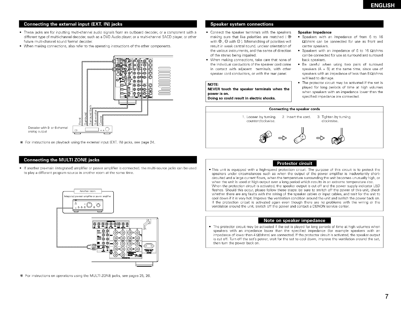
• These jacks are for inputting multi-channel audio signaEs from an outboard decoder, or a component with a
different type of multi-channel decoder, such as a DVD Audio player, or a multi-channel SACD playec or other
future multi-channel sound format decoder
• When making connections, aEso refer to the operat ng instructions of the other components
Decoder wth 8 or 6 cha+lne I _ o o O
a+laog output
For instructions on playback using the external input (EXT IN) jacks, see page 24
c _
c _
c _
c _
c _
c _
c _
c _
• Connect the speaker terminals with the speakers
making sure that like polarities are matched (_)
with _, O with O ) Mismatching of polarities will
resuk i+1weak central sound, U+lclear orientation of
the various i+lStruments, and the sense of direction
of the stereo being mpaired
• When making connections, take care that no+le of
the individual CO+ldUCtOrsof the speaker cord come
in contact with adjacent terminals, with other
speaker cord conductors, or with the rear panel
NOTE:
NEVER touch the speaker terminals when the
power is on+
Doing so could result in electric shocks.
Speaker Impedance
• Speakers with an impeda+lce of from 6 to 16
£2/uhms can be connected for use as front and
center speakers
• Speakers with an impedance of 6 to 16 _)./ohms
can be connected for use as surround and surround
back speakers
• Be careful when using two pairs of surround
speakers (A + B) at the same time, snce use of
speakers with an impedance of less than 8 £_/ohms
will lead to damage
• The protector circuit may be activated if the set is
played for long periods of time at high volumes
when speakers with an impedance lower than the
specified impedance are connected
Connecting the speaker cords
1 Loose+l by turning 2 hsert the cord 3 T+ghten by turning
counterclockwise clockwise
|" e-•
• If another pre-main (integrated) amplifier or power amplifier is connectedr the multi-source jacks can be used
to play a different program source in another room at the same time • This unit s equipped with a high-speed protectio+l circuit The purpose of this circuit is to protect the
speakers under circumstances such as when the output of the power amplifier is inadvertently shor_-
circuited and a large current flOWSr when the temperature surround ng the unit becomes unusually high, or
when the unit is used at high output over a long period which results in an extreme temperature rise
When the protection circuit is activated, the speaker output is cut off and the power supply indicator LED
flashes Should this occur, please follow these steps: be sure to switch off the power of this unit, check
whether there are any faults with the wiring of the speaker cables or input cables, and wait for the unit to
cool down if t s very hot Improve the ventilation cond tion around the unit and switch the power back on
If the protection circuit is activated again even though theEe are no problems with the wiring or the
vent ]ation around the unit, switch off the power and contact a DENON service center
• The protector circuit may be activated if the set is played for Io+lg periods of time at high volumes when
speakers with an impedance IoweE than the specified mpedance {for example speakers with an
impedance of IoweE than 4 _/ohms) are connected If the protector circuit is activated, the speaker output
is cut off Turn off the set's power, wait for the set to cool down, improve the ventilation around the set,
then turn the power back on
For instructions on operations using the MULTI ZONE jacks, see pages 25, 26
7
l_[t]]_S]g
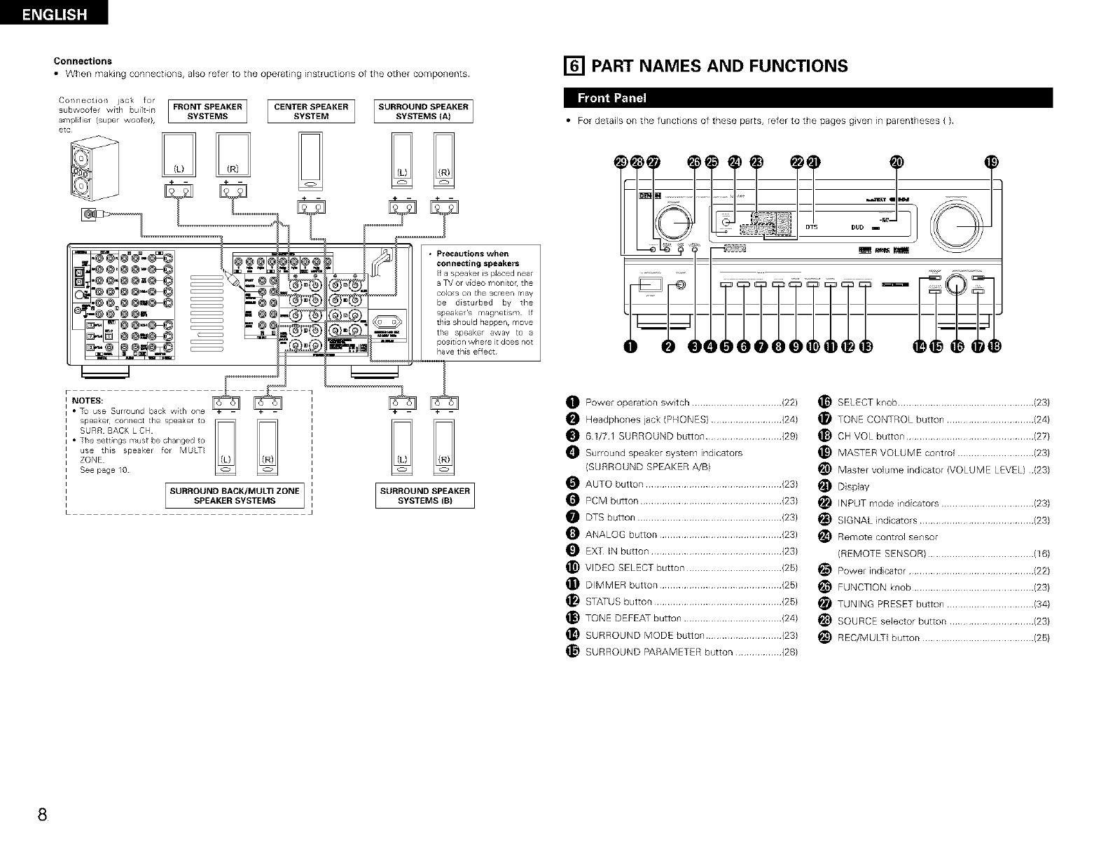
Connections [] PART NAMES AND FUNCTIONS
• When making connections, also refer to the operat ng instructions of the other components
Ia't_t'gl_rh'1_
c....... tie,, jaok fo, I [ I
subwooler with built in FRONT SPEAKER CENTER SPEAKER SURROUND SPEAKER
amplfier (super woofer}, SYSTEMS SYSTEM SYSTEMS (A)
etc
®@_
@@w_
_@@ @@=
3
m@4
=@4
-=@4
c _
C_
I NOTES:
• To use Surround baok with one
speaker¸ con_/ect the spea_er to
SURR BACKLCH
• The settings must be changed to
use this speaker for MULTI
ZONE
See page 10
SURROUND BACK/MULTI ZONE
SPEAKER SYSTEMS
• Precautions when
connecting speakers
f a speaker is placed near
a TV or video monitor the
colos on the screen may
be disturbed by the
speakers magnetism Jf
this should happen, move
the speaker away to a
position where it does not
have this effect
iSUR; O D E KERI
• For details on the functions of these parts, refer to the pages gven m parentheses ( )
hUb
I
Power operation switch ................................. (22)
O Headphones jack (PHONES} .......................... {24}
O 6¸1/7¸1 SURROUND button ............................ (29}
O Surround speaker system indicators
{SURROUND SPEAKER A/B}
O AUTO button .................................................. {23}
O PCM button .................................................... {23}
O DTS button ..................................................... {23}
O ANALOG button ............................................. {23}
O EXT IN button ................................................ (23}
_) VIDEO SELECT button ................................... {25}
DIMMER button ............................................. {25}
STATUS button ............................................... {25}
_) TONE DEFEAT button .................................... {24}
SURROUND MODE button ............................ (23}
_) SURROUND PARAMETER button ................. (28}
SELECT knob .................................................. (23)
TONE CONTROL button ................................ (2@
_) CH VOL button ............................................... (27)
_) MASTER VOLUME control ............................ (23)
_) Master volume indicator (VOLUME LEVEL} (23)
_ D splay
INPUT mode indicators .................................. (23)
_) SIGNAL ndcators .......................................... (23)
Remote control sensor
(REMOTE SENSOR) ....................................... (16)
_) Power indcator .............................................. (22)
FUNCTION knob ............................................. (23)
TUNING PRESET button ................................ (34)
_) SOURCE selector button ............................... {23)
_) REC/MULTI button ......................................... (25)
8
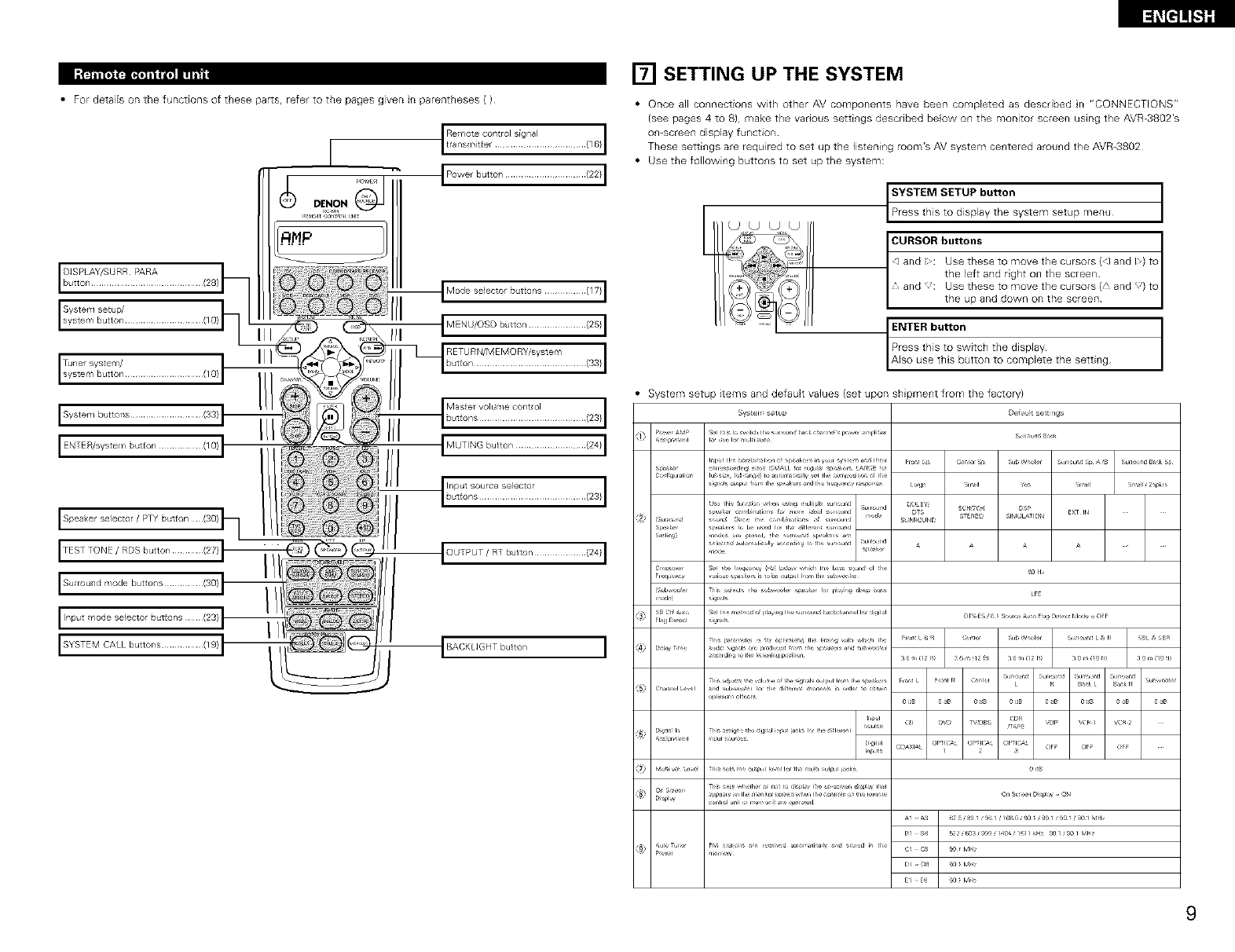
• For detaiB on the functions of these par_s, refer to the pages given in parentheses ( )
Systemsetup/
[] SETTING UP THE SYSTEM
• Once all connections with other AV components have been completed as described n "CONNECTIONS"
(see pages 4 to 8), make the various settings described below on the monitor screen using the AVR-3802's
on-screen display function
These settings are required to set up the listening room's AV system centered around the AVR-3802
• Use the following buttons to set up the system:
_ystem setup menu t
ENTER button
Also use this button to complete the setting
Press this to switch the display
System setup items and default values (set upon shipment from the factory)
SystelY setup Deist settilgs
S_l hr _re, ild, h ,r= n_ bak _ba:r_( peru r I11r S_r=_u:j BJk
k_ ,JrL I_r rl ,Jl i_:L
o,r _,dl, _bALL _X _ju_ p(_kr L#,R_E
DL
,,x, P_k
ii a_/lu ih_ _hh _ h S r,d OUlpUliR) H h s_lkt rs II_rd L!_IIP _ r,_l LR B_tkL i_kp _u '¢_ X It I
_i/! i'_ I? ...... ,.......................o...........o......
9
NOTES:
• The omscreen display signals are not output from the color difference {component) video signal
(MONITOR OUT) jacks
• The on-screen display signals are output with priority to the S-VIDEO MONITOR OUT iack during playback
of a video component For example, if the TV monitor is connected to both the AVR-BBO2's S-Video and
video monitor output jacks and signals are input to the AVR-3802 from a video source {VDI_ etc) connected
to both the B-Video and video input jacksr the on-screen display signals are output with priority to the S-
Video monitor output If you wish to output the signals to the video monitor output jack, do not connect a
cord to the S-ViDEO MONITOR OUT iack (For detaib, see page 16}
• The AVR-BBO2's on-screen d splay function is designed for use with high resolut on monitor TVs, so it may
be d fficult to read small characters on TVs with smafl screens or low resolutions
• The setup menu is not displayed when "HEADPHONE ONLY" is selected
I:FJt;Tt__iLr*3 _JFJ;TI
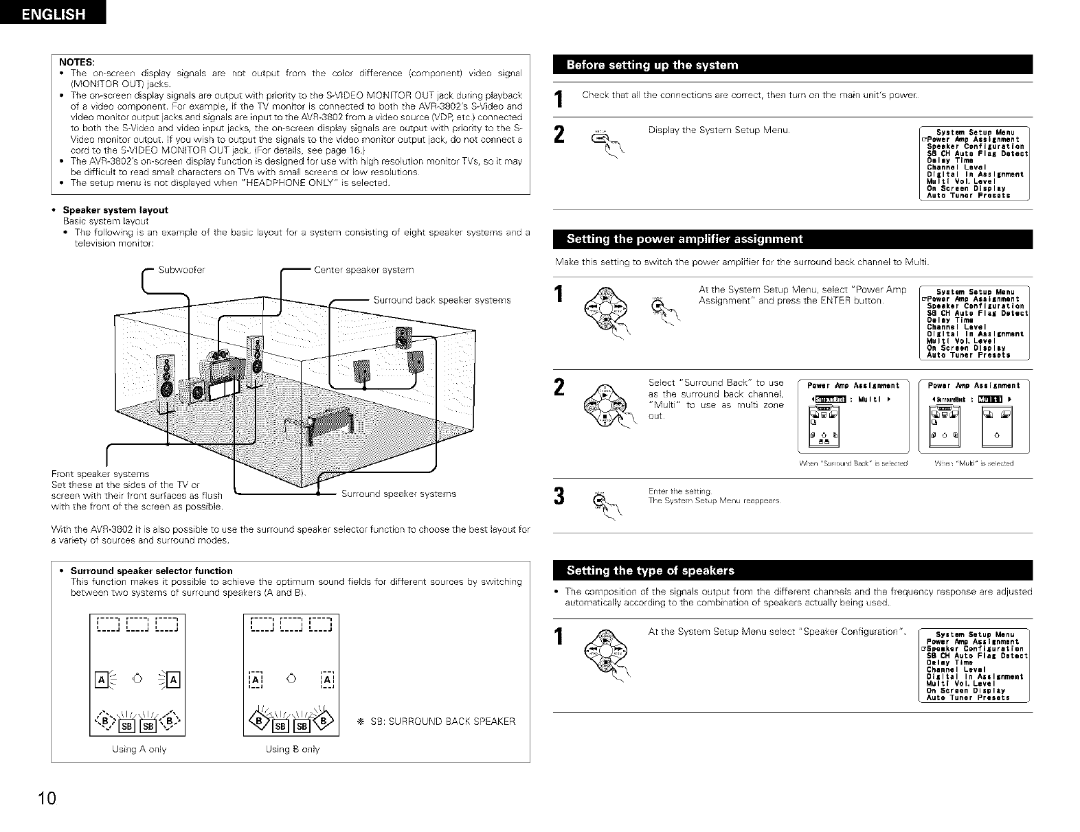
•Speaker system layout
Basic system layout
• The following is an example of the basic layout for a system consisting of eight speaker systems and a
television monitor: );_ )[,:LT*','.]il_.l iil ,'1II _ iTlllfJ_ i
Subwoofer
f
Front speaker systems
Set these at the sides of the TV or
screen with their front surfaces as flush
with the front of the screen as possible
_peaker system
peaker systems
Surround speaker systems
With the AVR-3802 it is also possible to use the surround speaker selector function to choose the best layout for
a variety of sources and surround modes
•Surround speaker selector function
This function makes it possible to achieve the optimum sound fields for different sources by switching
between two systems of surround speakers (A and B)
i i
L___J L___J L---J
SB:SURROUNDBACKSPEAKER
Using A only Using B only
I
2
Check that all the connections are correctr then turn on the main unit's power
Display the System Setup Menu _ syetem Setup Menu
_Power Amp Assilnment 1
Speeker Conflluratlon
SB CHAuto FlaK Detect
Delay Time
Channel Level
DIKItel In Aaal=nment
Multi VoL Level
On Screen Display
Auto Tuner Presets
Make this setting to switch the power amplifier for the surround back channel to Multi
At the System Setup Menu, select "Power Amp _ System Setup Menu
Assignment" and press the ENTER button _Power AmpAealsnment 1
Speaker Coflflluratlen
58 CH Auto Flei Detect
Delay Time
Channel Level
Oliltal In AeslBnmont
Multi Vol, Level
On Screen Display
Auto Tuner Presets
2Select "Surround Back" to use
as the surround back channel,
"Multi" to use as multi zone
out
Power Amp Assignment
4krrDuedBlCk: _)
When "Pvlulti_ _sselected
Enter tie setting
The Syste ¥_Setup Menu reappears
• The composition of the signals output from the different channels and the frequency response are adjusted
automatically according to the combination of speakers actually being used
At the System Setup Menu select "Speaker Configuration" syatem Setup Menu
Power AmpAssllnment 1
_Spelker Confiluration
SB CH AULOFlal Detect
Oeley Time
Channel Level
Olzltal In Aasllnment
Multi VoL Level
On Screen Display
Auto Tuner Presets
10
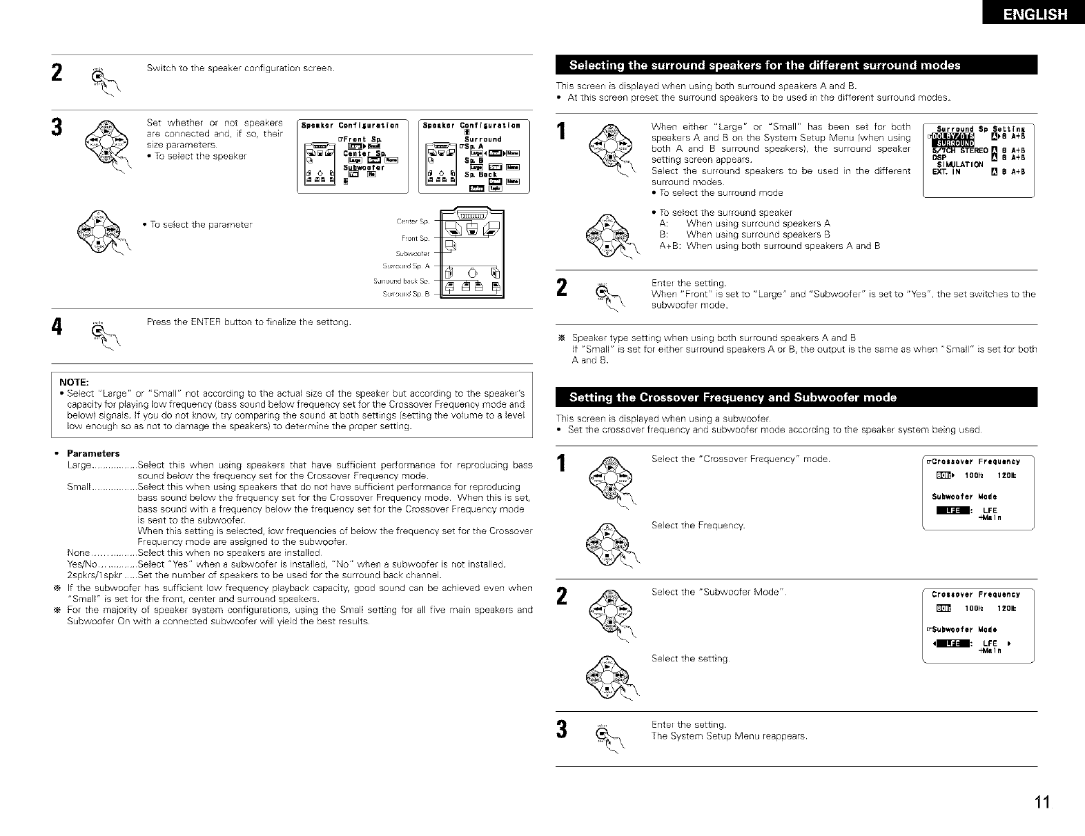
2Switch to the speakerconfiguration screen
3Set whether or not speakers
are connected and, if so, their
size parameters
•Tuselectthe speaker
• Tu select the parameter
5peeker Configuration
_Front Sl_
Center SD,
Subwoo fer
Speaker C_nf isurllt ion
SI_ Bask
center sp
F_ont Sp
Subwoofer
SumxJnd Sp A
SUlrour_d I_ck Sp
S_J_round Sp B
Press the ENTER button to finalize the settong
NOTE:
• Select ='Large r' or "Sr_qalF' l]ot according to the actual size of the speaker but according to the speakeE's
capacity for playing low frequency (bass sound below frequency set for the Crossover Frequency mode and
below) signals If you do not know, try comparing the sound at both settings (sett ng the volume to a Jevel
low enough so as not to damage the speakers) to determine the proper setting
This screen1 is displayed when using both surround speakers A and B
• At this screen preset the surround speakers to be used in the different surround modes
When either "Large" or "Small" has been set for both
speakers A and B on the System Setup Menu (when using
both A and B surround speakers), the surround speaker
setting screen appears
Select the surround speakers to be used in the different
surround modes
• Tu select the surround mode
• Tu select the surrou_ld speaker
A: When using surround speakers A
B: When using surround speakers B
A+B: When using both surround speakers A and B
Surround Sp $eLtlnz
REO _8 A+B
DSP [] 8 A+B
SIMULATION
EX_ IN [] e A+B
EnteE the setting
When "Front" is set to "Large" and "Subwoofer" is set to "Yes", the set switches to the
subwoofer mode
Speaker type setting when using both surround speakers A and B
If "Small" is set for either surround speakers A or B, the output is the same as when "Small" is set for both
A and B
This screen1 is displayed when using a subwoofer
• Set the crossover freque_lcy a_ld subwoofer mode according to the speaker system bei_lg used
Large ................. Select this when using speakers that have sufficient performance for reproducing bass 1
sound below the frequency set for the Crossover Frequency mode
Small ................. Select this when using speakers that do not have sufficient performance for reproducing
bass sound below the frequency set for the Crossover Frequency mode When this is set,
bass sound with a frequency below the frequency set for the Crossover Frequency mode
is sent to the subwoofer
When this setting is selected, low frequencies of below the frequency set for the Crossover
Frequency mode are assigned to the subwoofer
None ................ Select this when no speakers are installed
Y_s/No .............. Select "Yes" when a subwoofer is installed, "No" when a subwoofer is not installed
2spkrs/1 spkr Set the number of speakers to be used for the surround back channel
If the subwoofer has suff cient low frequency playback capacity, good sound can be achieved even when
"Small" is set for the front, center and surround speakers /
For the majority of speaker system configurations, using the Small setting for all five main speakers and
Subwoofer On with a connected subwoofer will yield the best results
Select the "Crossover Frequency" mode
Select the Frequency
_Crossover Frequency
E1T_) 1OOHz 120_
Subwoofer Mode
• _lra_-_: LFE
"Main
Select the "Subwoofer Mode"
Select the sett ng
l Crossover Frequency
lOOHz 120_
_Subwoofer Mode
4_BIlFa_--B_: LFE
-€4aln
Ente_ the setting
The System Setup Menu reappears
11
l_[l]!!_Sl]
NOTES:
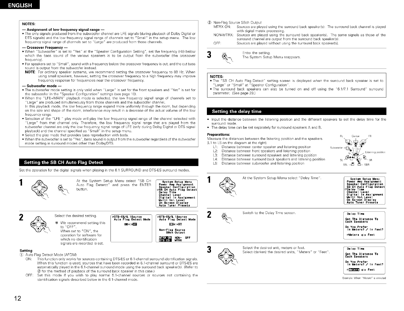
-- Assignment of low frequency signal range --
• The only sig_lals produced from the subwoofer channel are LFE signals (during playback of Dolby Digital or
DTS signals) and the low frequency signal range of channels set to "Small" in the setup menu The low
frequency signal range of channels set to "Large" are produced from those channels
-- Crossover Frequency --
• When r'Subwoofer" S set to "Yes" at the "Speaker Configuration Setting"r set the frequency (Hz) below
which the bass sound of the various speakers is to be output from the subwoofer (the crossover
frequency)
• For speakers set to "Smallr', sound with a frequency below the crossover frequency is cut, and the cut bass
sound is output from the subwoofer instead
NOTE: For ordinary speaker systemSr we recommend setting the crossover frequency to 80 Hz When
using small speakers, however, setting the crossovel frequency to a high frequency may improve
frequency response for frequencies near tile crossover frequency
-- Subwoofer mode --
• The subwoofer nlode setting is only valid when "Large" is set for the frollt speakers and "Y_s" is set for
the subwoofer in the "Speaker Configuration" settings (see page 10)
• When the r'LFE+MAIN" playback mode is selected, the low freque_lcy signal range of cha_lnels set to
"Large" are produced simultaneously from those cha_mels and the subwoofer channel
I_ this playback mode, the low frequency range expand more u_iformly through the room, but depend ng
on the sze and shape of the room, interfere_ce may result n a decrease of the actual volume of the low
frequency range
• Selection of the "LFE r, play mode will play the low frequency sgnal range of the cha_lnel selected with
"Large" from that channel only Therefore, the low frequency signal range that are played from the
subwoofer channel are only the low frequency signaJ range of LFE {o_ly duri_g Dolby Digital or DTS sig_al
playback) and the cha_nel specified as "SmalF' n the setup menu
• Select the play mode that provides bass reproduction with body
• When the subwoofer is set to "y_Sr'r bass sou_ld is output from the subwoofer regardless of the subwoofer
mode setti_g i_ surround modes other tha_ Dolby/DTS
Set the operation for the digtal signals when playing in the 61 SURROUND and DTS-ES surround modes
2
At the System Setup Me_u select "SB CH
Auto Flag Deterct" and press the ENTER
button
System Setup Menu t1
Power _'np Aeal|nment
Speaker Configuration
_SB CH Auto Flel Olteat
Oelay Time
Chlnnal Level
Oi|itml In Assilnment
Multi Vol, Level
On Screen Display
Auto Tuner Presets
Select the desired setting
We recommend settng this
to "OFF"
When set to "ON", the
operation for software for
which no identification
signals are recorded is set
_DTS-ES,/_ 1Source
Auto Flag Oeteet Mode
OTSE ='SOUr=.] 2
Auto Flal Detect Moda
Non-Flag Source
SBch Output
_NON- OFF
_,ffRX
Setting
"/l Auto Flag Detect Mode {AFDM)
ON: This function o_ly works for sources co_taining DTS-ES or 61-channel surround dentif cation sig_als
When this function is used, sources that have been recorded in 61-channel surround or DTS-ES are
automatically played in the 61 -channel surround mode using the surround back speaker(s) (Refer to
_2:for the method of playback of the surround back speaker n this case)
OFF: Set this mode if you wish to play normal _%channel sources or sources not containing the
identification signals described below in the 61-channel mode
,_2 NomFlag Source SBch Output
MTRX ON: Sources are played using the surrou_d back speaker(s) The surround back chan_el is played
with digital matrix processing
NON-MTRX: Sources are played using the surround back speaker(s) The same signals as those of the
surround channel are output from the surround back speaker(s)
OFF: Sources are played without using the surround back speaker(s)
Ente_ the setting
The System Setup Menu reappears
NOTES:
• The "SB CH Auto Flag Detect" setting scree_ is displayed when the surround back speaker is set to
"Large" or "Small" at "Speaker Conf guration"
=The surround back speakers can also be turned on and off using the "61/71 Surround" surround
parameten (See page 29)
• Input the distance between the listening position and the different speakers to set the delay time for the
surround mode
• The delay time can be set separately for surround speakers A and B
Preparatiorls:
Measure the distances between the listeni_g position and the speakers
(L1 to L5 on the d agram at the right)
LI : Dista_ce betwee_ center speaker and listening position
L2: Dista_ce betwee_ front speakers and listening position
L3: Dista_ce between surround speakers a_d liste_fing position
L4: Dista_ce betwee_ surround back speakers and listening positio_
LS: Dista_ce betwee_ subwoofer and listening position
3
At the System Setup Menu select "Delay T_me"
System Setup Menu t
Power Amp AasIKnmant
Speaker Configuration
SB CH Auto Flei Detect
_OQlay Timg
Channel Level
Oliltel In A_al_nment
Multi VoL Level
On Screen Display
Auto Tuner Presets
Switch to the Delay Time scree_ Oeley Time
Sit The Distance To
Each Speakers
Do You Prefer
In Meters? /In Feet?
_etera 4:_ Feet
Select the desired unit rmeters or feet
Select (darken) the desired units, r' Meters" or "Feet" Oeley Time
Set The Distance To
Each Speakers
Do You Prefer
In Meters? /In Feet?
_[_ _:_ Feet
Ex:,rnple When Meters _ _s se_e_d
12
_I,"t__ ;'_'_l'ill'_I_ I
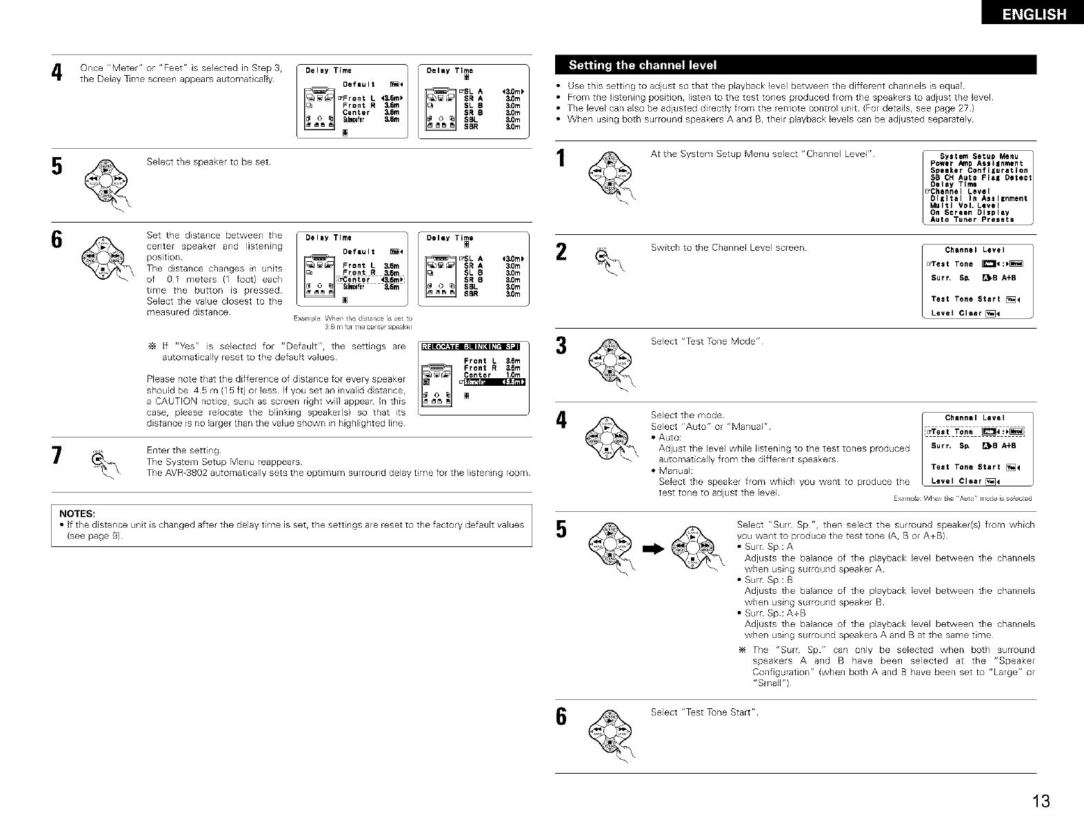
Once "Meter" or "Feet" s selected in Step 3,
the Delay T_me screen appears automat cally
Delay Time I
Default _4
_Front L
Front R _6m
Canter _6m
Su_fer _6m
[]
Delay Time
43,0m_
3,0m
30m
3,0m
3,0m
&Om
• Use this setting to adjust so that the playback level between the different channels is equal
• Fromthe fistening position, listen to the test tones produced fromthe speakers to adiust thelevel
• The level can also be adjusted direcdy from the remote control unit (For details, see page 27 )
• When using both surround speakers A and B, their playback levels can be adjusted separately
5Selectthe speakerto be set
Set the distance between the Delay Time
center speaker and listening /posdion_ _ i e_auit _
Pront L _6m
The distance changes in units _c_ R,_6_
of g_l meters I1 foot) each l_entar _.em_i
time the button IS bressed_ _ti_ &6m
Select the value closest to the
measured distance_
E×_r_lr_i_ _l_r_ ti_ _a_¢_ _ _ _o
_f r'_sr' is selected for "Default", the se_ings are
automatically reset to the default values
Please note that the difference of distance for every speaker
should be 45 m (15 ft} or less If you set an nvalid distance,
a CAUTION notice, such as screen right will appear In this
case, please relocate the blinking speaker(s) so that its
distance is no larger than the value shown in highlighted line
Delay Tilde ]
_SL A 2
$R A _m
SL B _dlm
SR 5 3.0m
SBL 3.0m
SBR 3,0m
Front L 3,1_m
4
7Enter the setting
The System Setup Menu reappears
The AVR-3802 automatically sets the optimum surround delay tree for the listening room
At the System Setup Menu select "Channel Level"
ISystem Setua Menu t
power _np Assilnment
Speaker Configuration
$B CH Auto Flal Detect
Oaley Time
_Dhannel Level
DIiItal In Assl|nment
Multi VoL Level
On Screen Display
Auto Tuner Presets
Switch to the Channel Level screen
Channel Level
u_rest Tone _:_
Surf, SO. _B A+8
Test Tone Start []4
Level Clear[_
Select "T_st Tune Mode"
Select the mode [- Channel Level
Select "Auto" Or "Manual" l[u'Te=t Tone _:;_
•Auto:
Adjust the level while listening to the test tones produced Surr" SI_ _B A+B
automatically from the different speakers
•Manual: Test Tone Start [_4
Select the speaker from which you want to produce tile Level Clear [_4
test tone to adjust tbe level Ex r_p_eWhe_ the /_ut_ r_odeiee ed
NOTES:
• If the distance unit is changed after the delay time is set, the setting° are reset to tee factory default values
(see page 9) 5Select "Surf Sp", then select the surround speaker(s) from which
you want to produce the test tone (A, B or A+B)
• Surr Sp: A
Adjusts the balance of the playback level between the channels
when using surround speaker A
• Surr Sp: B
Adjusts the balance of the playback level between the channels
when using surround speaker B
• Surr Sp: A+B
Adjusts the balance of the playback level between the channels
when using surround speakers A and B at the same time
The "Sure Sp" can only be selected when both surround
speakers A and B have been selected at the "Speaker
Configuration" {when both A and B have been set to "Large" or
'*Small*')
Select "T_stTune Start"
13
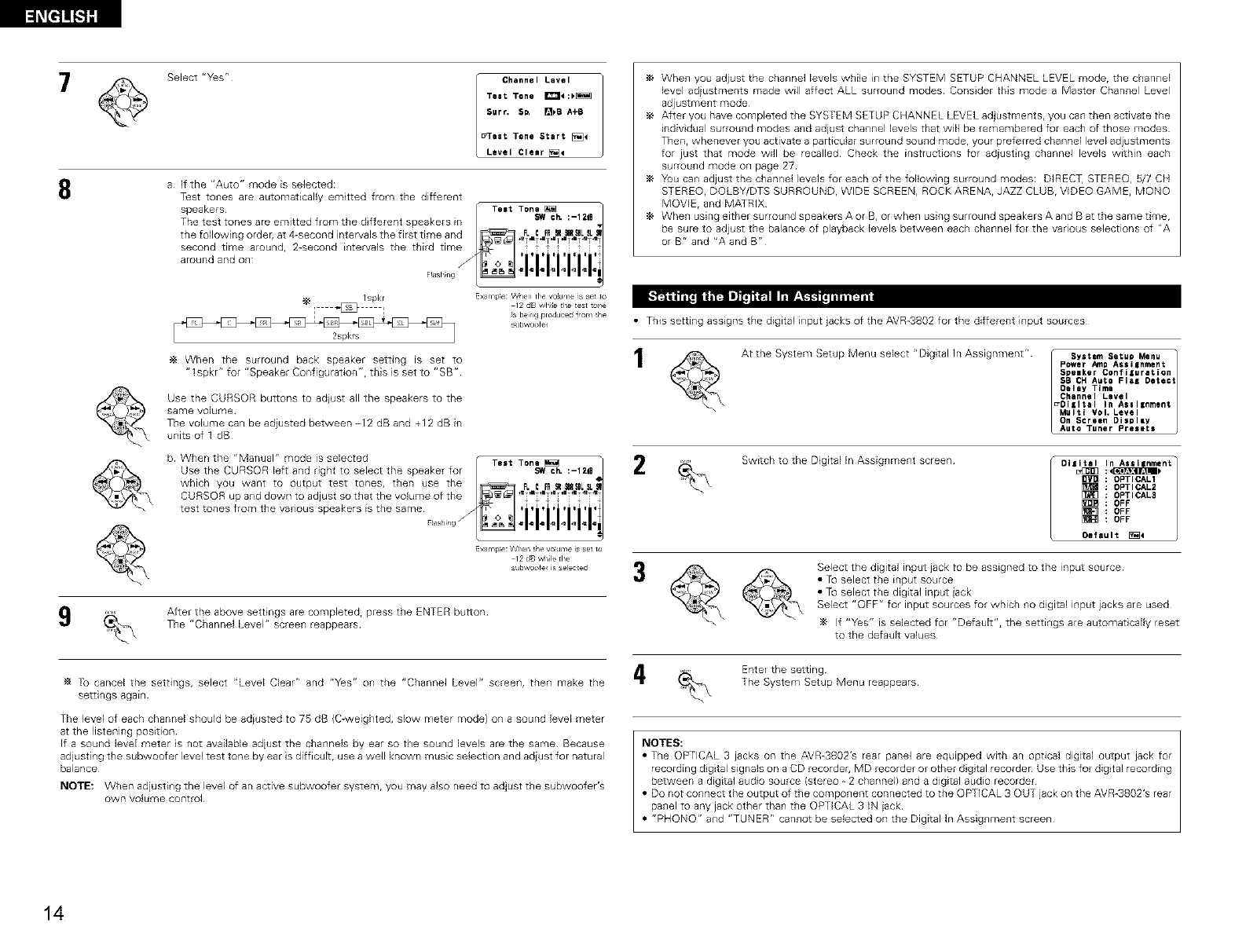
8
Select "Y_s r'
Channel Level
Test Tone _:)_
Surf. S_ []_B A+B
_eat Tone Start [_4
Level Cle=r[_
a If the "Auto" mode is selected:
T_st tones are automatically emitted from the different
Whe_l you adjust the channe] levels while i_1the SYSTEM SETUP CHANNEL LEVEL mode, the chan_lel
level adiustments made will affect ALL surround modes Consider this mode a Master Channel Level
adjustment mode
After you have completed the SYSTEM SETUP CHANNEL LEVEL adjustments, you can then activate the
individual surround modes and adjust channel levels that will be remembered for each of those modes
Then, whenever you activate a particular surround sound mode, your preferred channel level adjustments
for just that mode will be recalled Check the instructions for adiust ng channel levels within each
surround mode on page 27
You can adjust the channel levels for each of the following surround modes: DIRECT, STEREO, 5/7 CH
STEREO, DOLBY/DTS SURROUND, WIDE SCREEN, ROCK ARENA, JAZZ CLUB, VIDEO GAME, MONO
MOVIE, and MATRIX
When using either surround speakers A or B, or when using surround speakels A and B at the same time,
be sure to adjust the balance of playback levels between each channel for the various selections of "A
or Br' and "A and B"
Ispkr ExamPe Vt/]en fie v°iu _e s se to
l _ I12 dB w,hile the test 1o_1e
_s being produced _om _he
subw,oofe_
2spkrs
When the surround back speaker setting is set to
"lspkr"for"Speaker Configuration",thisis setto "SB"
Use the CURSOR buttons to adjust all the speakers to the
same volume
The volume can be adiusted between -12 dB and +12 dB in
units of 1 dB
b When the "Manual" mode is selected
ExarTip_e When _he vo_clme is set to
12 dB wMe the
subw,oote_ is selected
9After the above settings are completed, press the ENTER button
The "Channel Level" screen reappears
Tu cancel the settings, select "Level Clear" and "Yes" on the "Channel Level" screen, then make the
settings again
The level of each channel should be adiusted to 7S dB (C-weighted, slow meter mode) on a sound level meter
at the listening position
If a sound level meter s not available adiust the channels by ear so the sound levels are the same Because
adjusting the subwoofer level test tone by ear is difficult, use a well known music selection and adiust for natural
balance
NOTE: When adjusting the level of an active subwoofer system, you may also need to adjust the subwoofer's
own volume control
• This setting assigns the digital input jacks of the AVR-3802 for the different input sources
At the System Setup Menu select "Digital In Assignment" _ System Setup Menu
Power Amp Assilnment 1
Spelker Confiluration
SB CHAuto FlaK Detect
Oelay Time
Channel Level
_DIiItal In Asel|nment
Multi ¥ol. Level
On Screen Di$pley
Auto Tuner Presets
2Switch to the Digital In Assignment screen Dllit_al.,_uJ:<_lnASSl nment
OPTICAL1
OPTICAL2
[_] OPTICAL3
OFF
OFF
OFF
Oe_'auIt _4
Select the digital input jack to be assigned to the input source
a To select the ir_put source
a To select the digital input iack
Select "OFF" for input sources for which no digilal input jacks are used
If "Y_s" is selected for r'Default", the settings are automat cally reset
to the default values
Ente_ the setting
The System Setup Menu reappears
NOTES:
a The OPTICAL 3 jacks on the AVR-3802's rear panel are equipped with an optical digi[al output jack for
recording d gital signals on a CD recordeh MD recorder or other dig tal recorder Use this for dig tal recording
between a digital audio source (stereo - 2 channel) and a digital audio recorder
a Do not connect the output of the component connected to the OPTICAL 3 OUT jack on the AVR-3802's rear
panel to any jack other than the OPTICAL 3 IN jack
a "PHONO" and "TUNER" cannot be selected on the Digital In Assignment screen
14
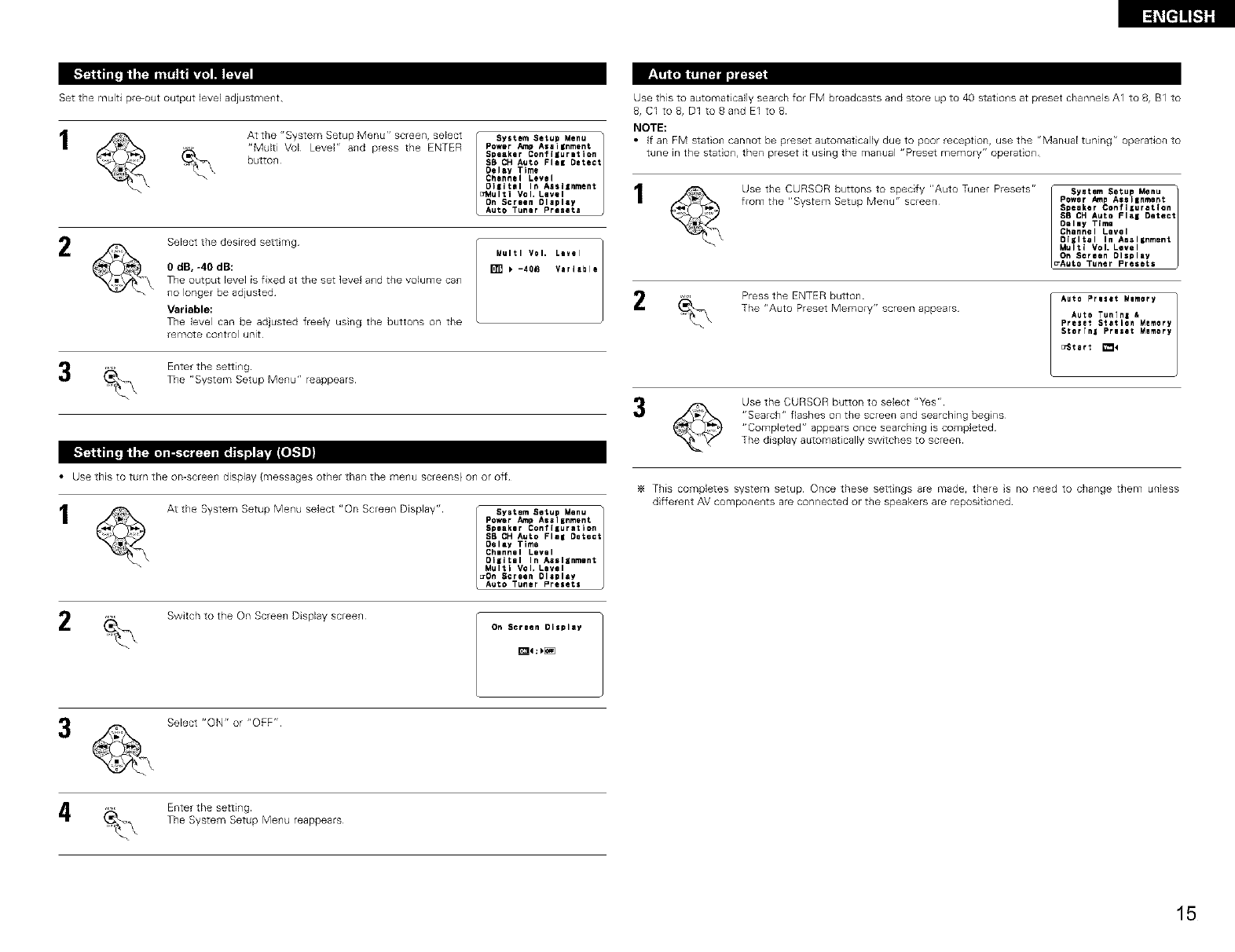
Set the multi pre-out output level adjustment
2
At the "System Setup Menu" screen, select
"Multi Vol Level" and press the ENTER
butto_
Select the desired sett mg
ISystem Setup Menu
Power Amp Assignment
Speaker Conflluretlon
SB CH Auto Flee Detect
Oelay Time
Channel Level
OIiItel In Assllnment 1
a_,tulti Vol, Level
On Screen Dlapley
Auto Tuner Preeete
0 dB, -40 dB:
The output level is fixed at the set level and the volume can
no longer be adjusted
Variable:
The (evel can be ad}usted freely using the buttons on the
remo'_e control unit
Enterthe setting
The "System SetupMenu"reappears
Multi Vel. Level ]2
[] _ -401_ Variable
Use this to automaticafly search for FM broadcasts a_d store up to 40 station,s at preset channels A1 to 8, B1 to
8, Cl to 8, D1 toSand E1 to8
NOTE:
If _r} F_I stat_o{] caF_r}ot be p_e_et a_to_at[cal_y d_e to poor _eceptJor} 7 _se _he UM_r_a_ t_F_iF_g r_ operat_or_ _
tune in the stat o{_, then preset it using the manual "Preset memory" operat o{_
Use the CURSOR buttons to specify "Auto Tuner Presets" r System Setup Menu
from the "System Setup Menu" screen¸ Power AmpAseIInment
Speeker Confiluratlon
S8 CHAuto Fieg Detect
Deimy Time
Chennei Levei
OIgitei in Aeeignment
Mu_t( Vol_ Level
On Soreen DIspiay
_Auto Tu_er _resets
Press the ENTER button
The "Auto Preset Memory" screen appears
Auto Preset _e_ory
Auto TunTnz &
Preset Station _e_ory
5torTnl Preset Memory
_Stert _<
Use the CURSOR button to select "Yes"
"Search" flashes on the screen and searching begins
"Completed" appears once searching is completed
The display automatically switches to screen
• Use this to turn the omscreen display (messages other than the menu screens) on or off
At the System Setup Menu se(ect "On Screen Display" r System Setup Menu
Power Amp Assignment
Speaker Conflluretlon
SB CH Auto Flel Detect
Dolly Time
Channel Level
Ol¢ltel In Assignment
Multi Vol, Level
_On Screen Display
Auto Tuner Presets
This completes system setup Once these sett ngs are made, there s no need to change them unless
different AV components are connected or the speakers are repos toned
2Switch to the On Screen Display screen On Screen Display
Select "ON" or "OFF"
Enter the setting
The System Setup Menu reappears
15
l_El]!_ql]
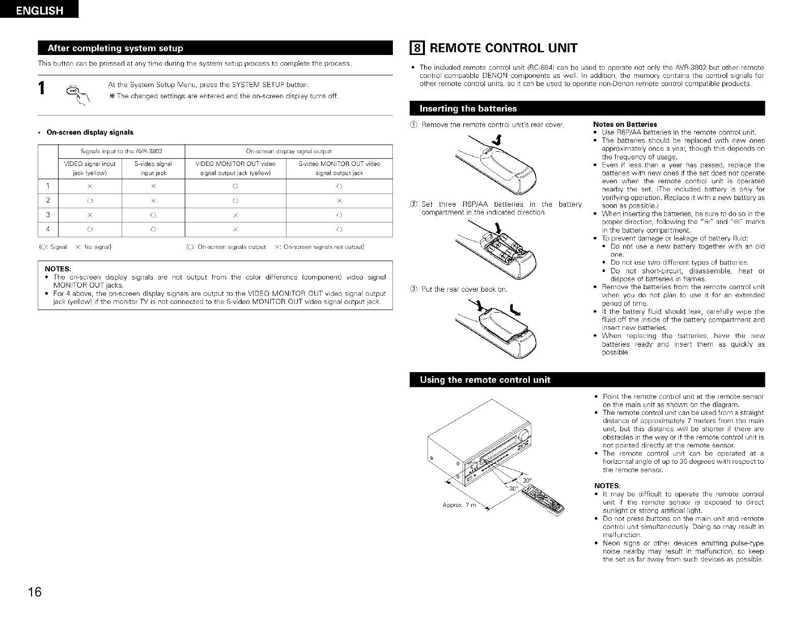
This button can be pressed at any time during the system setup process to complete the process
At the System Setup Menu, press the SYSTEM SETUP button
The changed settings are entered and the on-screen display turns off
• On-screen display signals
Signa}si/put o the AVR3802 ©/screen display signa output
VIDEO sigllal input Swideo signa] VDEO MONITOR OUT vdeo S video MONITOR OUT video
ack (yelow} input jack signal output jack {yelow} signal output ack
1 x x ( )
2 0 x ( x
3x(xO
4O O x O
{(_: Signa} X: NOsignal} (O: O/ screen signals output X: On screen s gnals not output)
NOTES:
• The on-screen dsplay signals are not output from the color difference (component) video sgnal
MONITOR OUT jacks
• For 4 above, the on-screen display signals are output to the VIDEO MONITOR OUT video signal output
jack (yellow) if the monitor TV is not connected to the S-video MONITOR OUT video signal output jack
[] REMOTE CONTROL UNIT
• The included remote control unit (RC-884) can be used to operate not only the AVR-3802 but other remote
control compatible DENON components as well In addtion, the memory contains the control signals for
other remote control units, so it can be used to operate non-Denon remote control compat ble products
'il Remove the remote control unit's rear cover
"/2 Set three R6P/AA batteries in the battery
compartment in the indicated direction
@ Put the rear cover back on
Notes on Batteries
• Use R6P/AA batteries in the remote control unit
• The batteries should be replaced with new ones
approximately once a year, though this depends on
the frequency of usage
• Even f less than a year has passed, replace the
batteries with new ones f the set does not operate
even when the remole control unit s operated
nearby the set {The nduded battery is only for
verifying operation Replace it with a new battery as
soon as poss ble )
• When nserting the battedesr be sure to do so in the
proper direction, following the "(_," and "(Y" marks
m the battery compartment
• Tu prevent damage or leakage of battery fluid:
• Do not use a new battery together with an old
one
• Do not use two different types of batteries
• Do not short-circuit, disassembler heat or
dispose of battedes in flames
• Remove the batteries from the remote control unit
when you do not plan to use it for an extended
period of time
• If the battery fluid should leak, carefully wipe the
fluid off the inside of the battery compartment and
insert new batteries
• When replacing the batteries, have the new
batteres ready and insert them as quickly as
possible
IL_'_t* *t=, - ,t ,1_
Approx 1m
• Point the remote control unit at the remote sensor
on the main unit as shown on the diagram
• The remote control unit can be used from a straight
d stance of approximately 7 meters from the main
unit, but this d stance will be shorter if there are
obstacles in the way or if the remote control unit is
not pointed directly at the remote sensor
• The remo'_e control unit can be operated at a
horizontal angle of up to 30 degrees with respect to
the remote sensor
NOTES:
• It may be difficult to operate the remote control
unit if the remote sensor s exposed to direct
sunlight or strong artif cial light
• Do not press buttons on tile main unit and remote
control unit simultaneously Doing so may result in
malfunction
• Neon signs or other devices emitting pulse-type
nose nearby may result in malfunction, so keep
the set as far away from such devices as possible
16
I_i'l
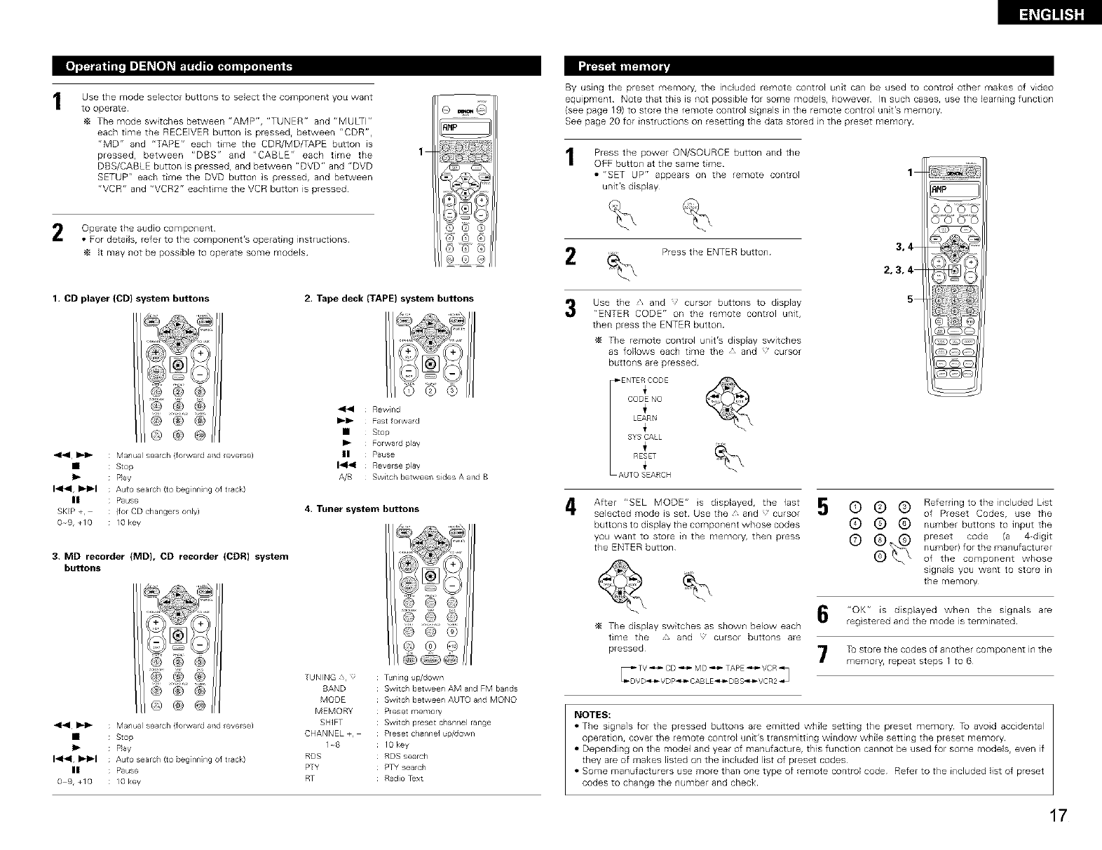
Use the mode selector buttons to select the component you want
to operate¸
The mode switches between "AMP", "TUNER" and "MULTI"
each time the RECEIVER button is pressed, between "CDR",
"MD" and "TAPE" each time the CDR/MD/TAPE button is
pressed, between "DBS" and "CABLE" each tree the
DBS/CABLE button is pressed, and between "DVD" and "DVD
SETUP" each time the DVD button s pressed, and between
"VCR" and "VCR2" eacht me the VCR button is pressed
1
Operate the audio component
•For details, refer to the component's operating instructions
It may not be possible to operate some models
1. CD player (CD} system buttons 2. Tape deck (TAPE) system buttons
@@@
@ @ @
®®@
44 I_1_ : Manual search (forwa d and everse)
• : Stop
I)- : P}ay
1"_41, !)_l_l : Auto searc/ (te beg[nn ng of track)
II : Pause
SKIP +, (for CD changes only)
09,+10 : lOkey
44 Rewnd
I_1_ Fast forward
• Step
Ib Forward play
II Pause
14141 Reverse play
A/B Switch between sides A and B
4, Tuner system buttons
3, MD recorder (MD}, CD recorder (CDR) system
buttons
@ @ @
® @
®®@
4141 I_1_ : Manual search (forwa d and everse)
• : Stop
I)- : P}ay
1"_41, I)_1_1 : Auto searc/ (te beg[nn ng of track)
II : Pause
09,+10 : lOkey
TUNING 3, :
BAND
MODE
MEMORY
SHIFT
CHANNEL+,
1-8
RDS
PTY
RT
© @ @
© @ ®
Tuning up/dewn
Switc / between AM and FM bands
Switch between AUTO and MONO
Preset memory
Switch preset channel range
Preset channel _p/dewn
10key
RDS search
PTY search
Radio Text
By using the preset memory, the included remote control unit can be used to control other makes of video
equipment Note that this is not possible for some models, however In such cases, use the learning function
(see page 19) to store the remote control signals in the remote control unit's memory
See page 20 for instructions on resetting the data stored in the preset memory
Press the power ON/SOURCE button and the
OFF button at the same time
• "SET UP" appears on the remote control
unit's display
Press the ENTER button
Use the s and cursor buttons to display
"ENTER CODE" on the remote control unit,
then press the ENTER button
The remote control unit's display swiLches
as follows each time the • and cursor
buttons are pressed
1
4
_ENTERCODE
CODENO
i
LEARN
i
SYSCALL
i
RESET
AUTO SEARCH
After "SEL MODE" s dsplayed, the last
selected mode is set Use the A and cursor
buttons to display the component whose codes
you want to store in the memory, then press
the ENTER button
The display switches as shown below each
time the , and cursor buttons are
pressed
3,4
2,3,4
5
Referring to the included List
© (9 (9 of Preset Codes, use the
(9 (9 (9 number buttons to input the
(9 _ i_'_ preset code (a 4-digit
number) for the manufacturer
of the component whose
signals you want to store in
the memory
"OK" is displayed when the signals are
reg stered and the mode is terminated
To store the codes of another component in the
memory, repeat steps 1 to 6
NOES:
• The signals for the pressed buttons are emitted while setting the preset memory Tu avoid accidental
operation, coveE the remote control unit's transmitting window while setting the preset memory
• Depending on the model and year of manufacture, this function cannot be used for some models, even if
they are of makes listed on the included list of preset codes
• Some manufacturers use more than one type of remote control code Refer to the included list of preset
codes to change the number and check
17
The presetcodesareasfollowsuponshipmentfrom thefa_oH andafterresetting:
T% VCR ...................................................................... HITACHI
CD, MD, TAPE, CDR, VD_ DVD, DVD SETUP ......... DENON
DBS ........................................................................... GENERALINSTRUMENT
CABLE ....................................................................... JERRQLD
Press the power ON/SOURCE button and the
OFF button at the same time
• "SET UP" appears on the remote control
unit's display
i_ Press the and <;' CUrsor
buttons to display the registered
preset memory on the remote
control unit's display and check
5Press the ENTER button to
terminate
2 Press the ENTER button
3Use the and cursor buttons to display
"CODE NO" on the remote control unit, then
press the ENTER button
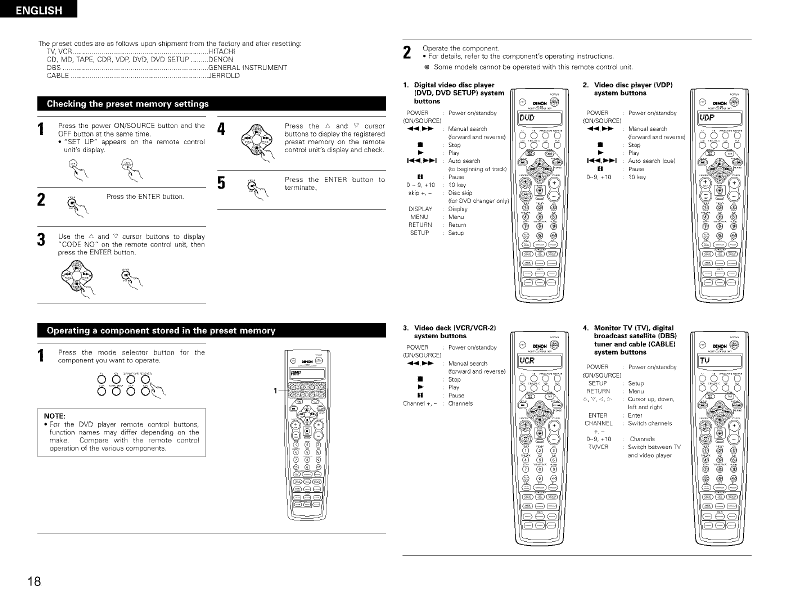
1Press the mode selector button for the
component you want to operate
ouo o%
NOTE:
• For the DVD player remote control buttons,
function names may differ dependng on the
make Compare with the remote control
operation of the various components
Operate the component
• For details, refer to the component's operating instructions
Some models cannot be operated with this remote control unit
1. Digital video disc player
(DVD, DVD SETUP) system
buttons
POWER Power on/standby
(ON/SOURCE)
414 _-I_ Manual searc /
(forward and reverse)
• Stop
I_ Play
I-_r_l, I_1_1 Auto search
(to beg nning of track)
|1 Pause
0 9, T10 lOkey
skip +, Disc skip
(for DVD cha/ger ony}
DISPLAY Display
MENU Menu
RETURN Return
SETUP Setup
DUD
0000
©'_'0 0
@@@
®®®
2. Video disc player (VDP)
system buttons
Power on/standby
Manual search
(forward and reverse)
Stop
Play
Auto sealch )cue)
Pause
lOkey
@@®
1
3. Video deck (VCR/VCR-2)
system buttons
Power on/standby
Manual search
(forward aid reverse)
Stop
Play
Pause
Channels
UCR
0000
(0 ® ®
4. Monitor TV (TV), digital
broadcast satellite (DBS)
tuner and cable (CABLE)
system buttons
POWER Power on/standby
(ON/SOURCE)
SETUP Setup
RETURN Menu
,, 4, ; Cursor up, down,
left and rg/t
ENTER Enter
CHANNEL Switch c/annels
Channe)s
TV/VCR Switc 1 between TV
and video playe
TU
)OOO
)000
@@@
18
I_t]]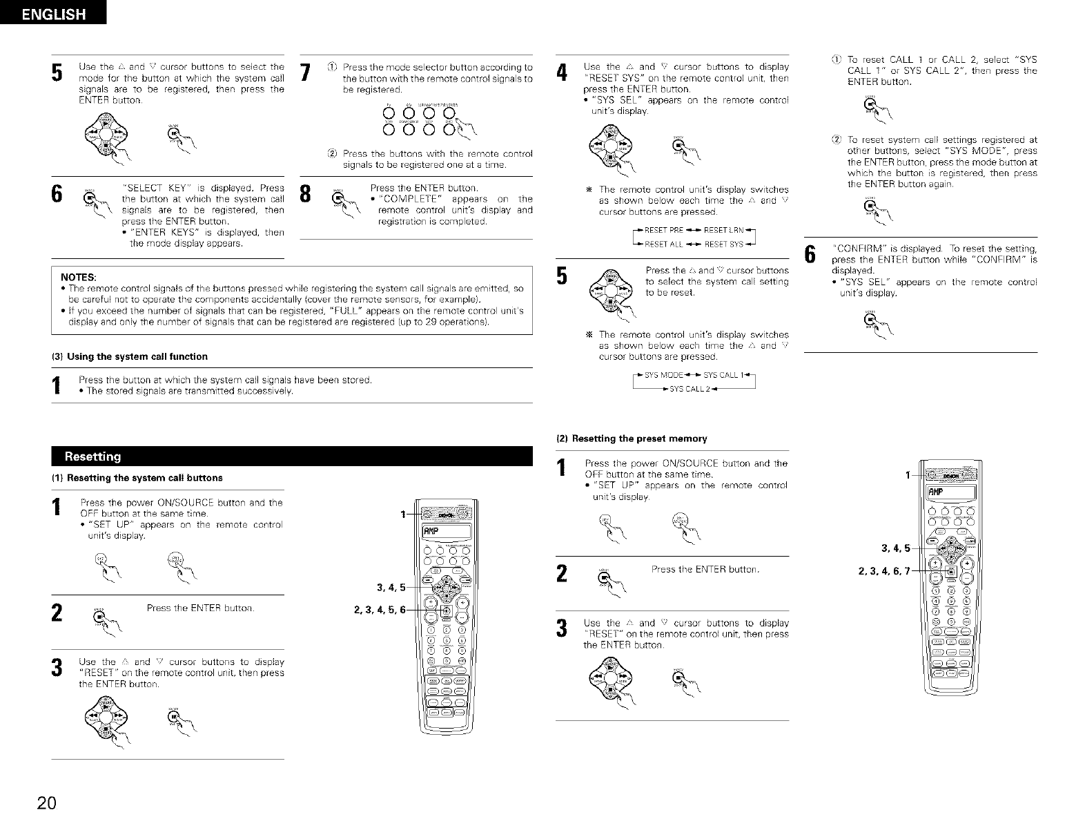
l_[=]]_S]g
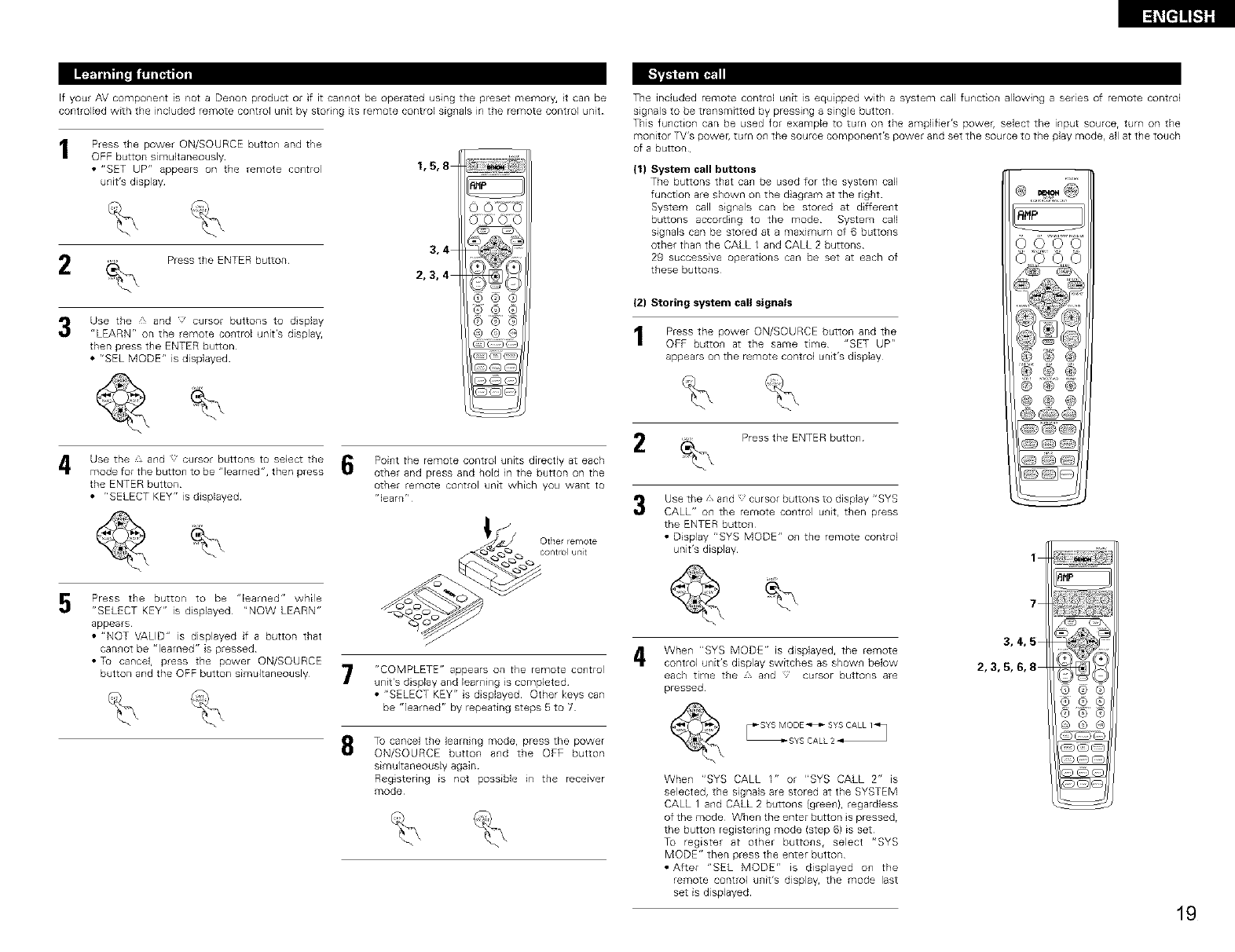
5
6
Use the , and J cursor buttons to select the
mode for the button at which the system call
signaEs are to be registered, then press the
ENTER button
"SELECT KEY" is displayed Press
the button at which the system call
signaEs are to be registered, then
press the ENTER button
• "ENTER KEYS" is dsplayed, then
the mode display appears
I Press the mode selector button according to 4
the butto_ with the remote control signals to
be registered
_2_ Press the buttons with the remote control
signals to be reg stered one at a tme
Press the ENTER button
• "COMPLETE" appears on the
remote control unit's display and
regEstrat on is completed
NOTES:
• The remote control signals of the buttons pressed while registering the system call sig_lals are emitted, so
be careful not to operate the components accidentally {cover the remote sensors, for example)
• if you exceed the number of signals that can be registered, "FULL" appears on the remote control unit's
display and only the number of signals that can be registered are registered (up to 29 operat ons)
(3) Using the system call function
IPress the button at which the system call signab have been stored
• The stored signals are transmitted successively
Use the , and _ cursor buttons to display
r'RESET SYS" on the remote control unit, then
press the ENTER button
• "SYS SEL" appears on the remote control
unit's display
The remote control unit's display switches
as shown below each time the and
cursor buttons are pressed
5Press the {, and cursor butto_ls
to select the system call setting
to be reset
_4 The remote control unit's display switches
as shown below each time the and
cursor buttons are pressed
F¸,
l,= To reset CALL 1 or CALL 2, select "SYS
CALL 1" or SYS CALL 2", then press the
ENTER button
"_2 Tu reset system call settings regstered at
other buttons, select "SYS MODE", press
the ENTER butto_, press the mode button at
which the button is registered, then press
the ENTER button again
6"CONFIRM" is displayed To reset the setting,
press the ENTER button while "CONFIRM" is
displayed
• "SYS SEL" appears on the remote control
unit's display
I-'_]
(1) Resetting the system call buttons
Press the power ON/SOURCE butto_ and the
OFF button at the same time
• "SET UP" appears on the remote control
unit's display
2Press the ENTER button
Use the and ' cursor buttons to dsplay
"RESET" on the remote control unit, then press
the ENTER button¸
1
3,4,5
2,3,4,5,6
{2) Resetting the preset memory
Press the power ON/SOURCE button and the
OFF butto_ at the same time
• "SET UP" appears on the remote control
unit's display
2Press the ENTER butto_
Use the and cursor butto_ls to display
"RESET" on the remote control unit, then press
the ENTER button¸
1
3,4,5
2,3, 4, 6,7
2O
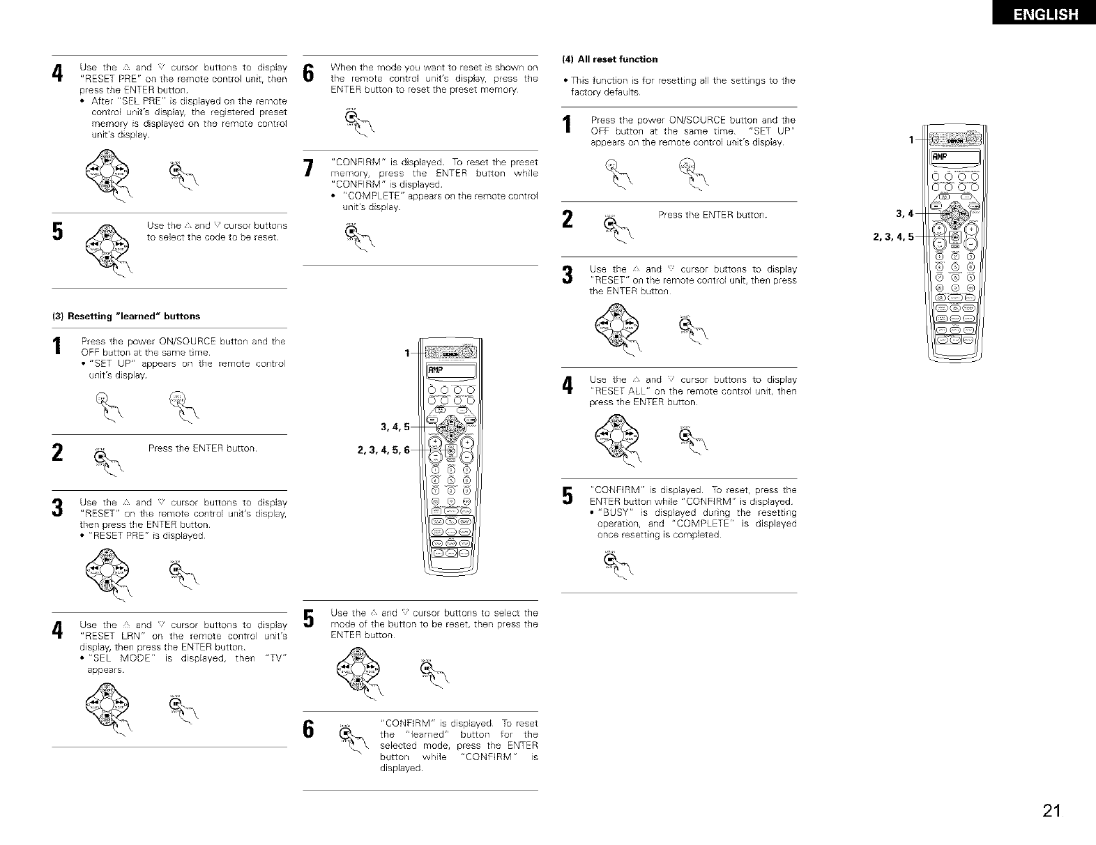
4Use the £ and _' cursor buttons to dsplay
"RESET PRE" on the remote control unit, then
press the ENTER button
• After "BEL PRE" is displayed on the remote
control unit's display, the registered preset
memory is displayed on the remote control
unit's display
5Use the and :_ cursor buttons
to select the code to be reset
(3) Resetting "learned" buttons
Press the power ON/SOURCE butto_ and the
OFF button at the same time
•"SET UP" appears on the remote co_ltrol
unit's display
2 Press the ENTER button
Use the and cursor buttons to dsplay
"RESET" on the remote control unit's display,
then press the ENTER button
•r'RESET PRE" is displayed
When the mode you waist to reset is shown on
the remote control unit's displayr press the
ENTER button to reset the preset memory
7"CONFIRM" is dsplayed To reset the preset
memory, press the ENTER button while
"CONFIRM" is displayed
•"COMPLETE" appears on the remote control
unit's display
(4) All reset function
• This function is for resett ng all the sett ngs to the
factory defaults
Press the power ON/SOURCE button and the
OFF butto_ at the same time "SET UPr'
appears on the remote control unit's display
2Press the ENTER butto_
1
3,4
2,3,4,5
1
3,4,5
2,3,4,5,6
Use the and cursor butto_ls to display
"RESET" on the remote control unit, then press
the ENTER button¸
Use the ,, and cursor butto_ls to display
"RESET ALL" on the remote control unit, then
press the ENTER button¸
5"CONFIRM" is displayed To reset, press the
ENTER button while "CONFIRM" is displayed
• "BUSY" is displayed during the resetting
operation, and "COMPLETE" is displayed
once resetti_g is completed
4Use the ' and 'cursor buttons to display
"RESET LRN" on the remote co_trol unit's
display, then press the ENTER button
•r'SEL MODE" is displayed, then "TV"
appears
Use the 1, and }' cursor buttons to select the
mode of the button to be reset, then press the
ENTER button
6"CONFIRM" is displayed Tu reset
the "learned" button for the
selected mode, press the ENTER
button while "CONFIRM" is
displayed
21
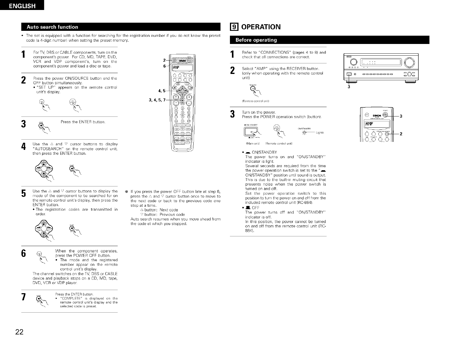
• The set is equipped with a function for searching for the registration number if you do not know the preset
code {a 4-dig t number) when setting the preset memory
For TV DBS or CABLE components, turn on the
component's power For CD, MD, TAPE, DVD,
VCR and VDP component's, turn on the
component's power and load a disc or tape
2
6
2Press the power ON/SOURCE button and the
OFF button simultaneously
•"SET UP" appears on the remote control
unit's display 4,5
3,4,5,7
Press the ENTER button
Use the and ' cursor buttons to display
"AUTOSEARCH" on the remote control unit,
then press the ENTER button¸
5Use the * and cursor buttons to display the
mode of the component to be searched for on
the remote control unit's display, then press the
ENTER button
• The registration codes are transmitted in
order
If you press the power OFF button late at step 6,
press the, and cursor button once to move to
the next code or back to the previous code one
step at a time
J, butto_: Next code
button: Previous code
Auto search resumes when you move ahead from
the code at which you stopped
[] OPERATION
Refer to "CONNECTIONS" (pages 4 to 8) a_d
check that all connections are correct
2 Select "AMP" using the RECEIVER button
(only when operating with the remote control
unit)
%
Re _te contro u/J9
Turn on the power
Press the POWER operation switch (button)
_L_ghts
•_ ON/STANDBY
The power turns on and "ON/STANDBY"
indicator s light
Several seconds are required from the time
the power operation switch is set to the "_
ON/STANDBY" position until sound s output
This s due to the built-in muting circuit that
prevents noise when the power switch is
turned on and off
Set the power operation switch to this
position to turn the power on and off from the
included remote control unit (RC-884)
• Im OFF
The power turns off and "ON/STANDBY"
indicator s off
In this position, the power cannot be turned
on and off from the remote control unit (RC-
884)
[=,o{,..:::
oooo . .
[C: :°:
3
6When the component operates,
press the POWER OFF button
• The mode and the registered
number appear on the remote
control unit's display
The channel switches on the TV, DBS or CABLE
device and playback stops on a CD, MD, tape,
DVD, VCR or VDP player
Press the ENTER buttol/
• "COMPLETE" is displayed on the
emote col/trol uTlit's display and the
selected code is preset
22
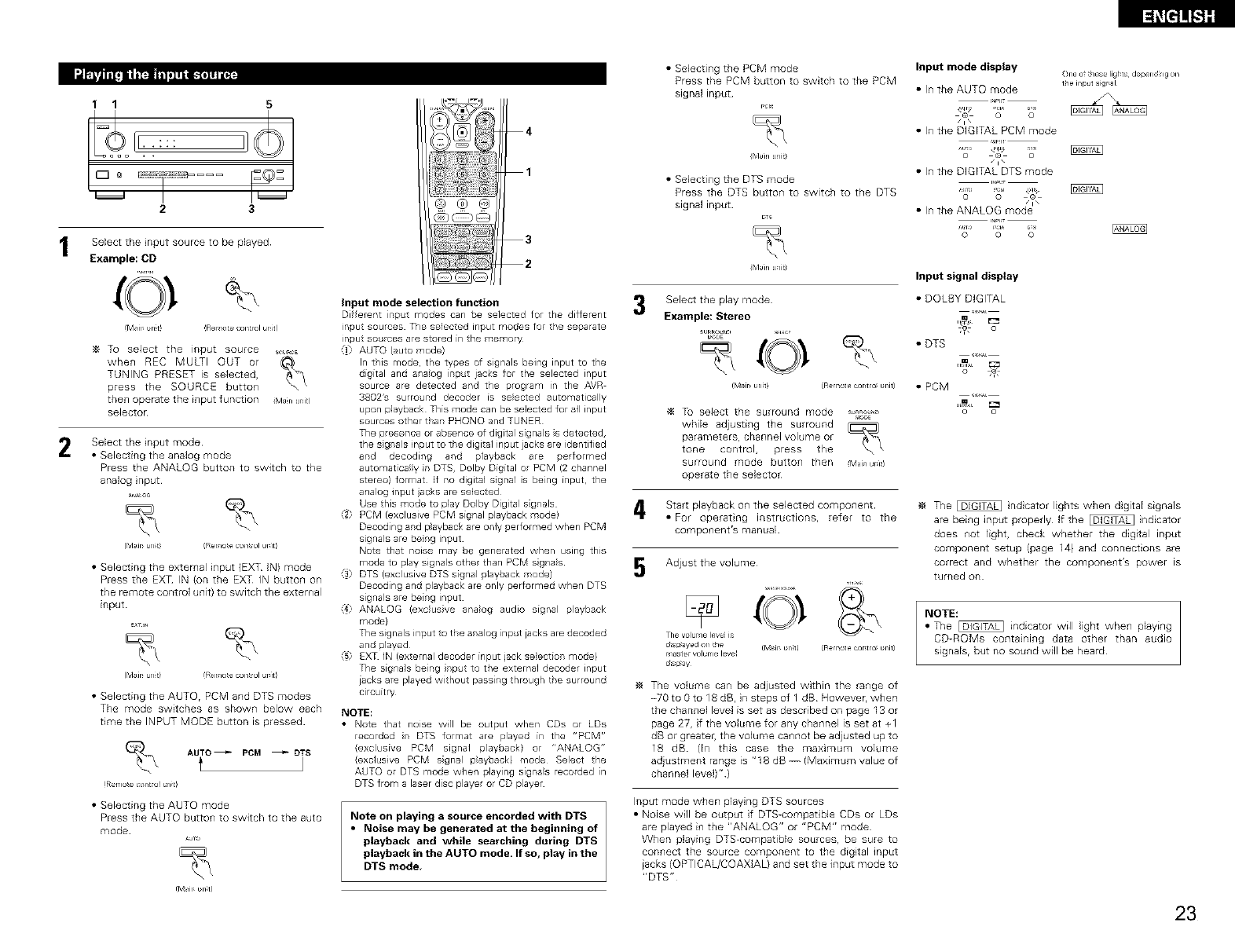
2
1 1 5
23
Select the nput source to be played
Example: CD
(M_ir_ _n_t! !Remo_e control urfit)
To select the input source SO,ROE
when REC MULTI OUT or
TUNING PRESET is selected,
press the SOURCE button
then operate the input function iMan unit)
selector
Select the nput mode
•Selecting the analog mode
Press the ANALOG button to switch to the
analog nput
(Mair_ brfit/ (Remo[e con[rol ur_it)
• Selecting the external input (EXT IN) mode
Press the EXT IN (on the EXT IN button on
the remote control unit) to switch the external
input
(Msir_brfit) (Remo[econ[rolur_itl
• Selecting the AUTO, PCM and DTS modes
The mode switches as shown below each
time the INPUT MODE button is pressed
AUTO _PCM _DTS
t
(Rerno_e contr.! un_tl
• Selecting the AUTO mode
Press the AUTO button to switch to the auto
mode AJo
(M_ir_ _n_t!
4
1
@@@
3
2
input mode selection function
Different nput modes can be selected for the different
input sources The selected input modes for the separate
inputso ces are stored in the memory
_1 AUTO (auto mode)
In this mode, tl:e types of signals being input to the
digital and a aog rput jacks for the selected input
source are detected and the program in the AVR
3802's surro rd decoder is selected automatically
upon playback This mode can be selected for all input
sources other that PHONQ and TUNER
The presence or absence of digital signals s detected,
the s grals input to the digital input iacks are identified
and decoding and playback are performed
automaticaly n DTS, Dolby Digital or PCM (2 channel
stereo) format If no digital sgnal s being input, the
analog input acks are selected
Use this mode to play Dolby Digital s grals
_2 PCM (exclusive PCM signal playback mode)
Decoding and playback are only performed when PCM
signals are beng input
Note that noise may be generated when using this
mode to play signals other than PCM sgras
_3) DTS (exclusive DTS signal playback mode)
Decoding and playback are only performed when DTS
signals are beng input
ANALOG (exc}usve analog audio signal payback
mode)
The signals input to the anaog inpt iacks are decoded
and olayed
_5 EXT IN (external decoder input jack selection mode)
The signals beng rp ttothe externaldecoder input
iacks are played without pass ng through the surround
circuitry
NOTE:
• Note that noise will be output when CDs or LDs
recorded rDTS format are played in the "PCM r'
(exclusive PCM signal payback) or "ANALOG"
(exclusive PCM sgnal playback) mode Select the
AUTO or DTS mode when playing sigras recorded in
DTS from a laser disc player or CD player
Note on playing asource encorded with DTS
• Noise may be generated at the beginning of
playback and while searching during DTS
playback in the AUTO mode. If so, play in the
DTS mode,
3
• Selecting the PCM mode
Press the PCM button to switch to the PCM
signal input PCr_
(Main unit)
• Selecting the DTS mode
Press the DTS button to switch to the DTS
signal input
(Main uait)
Select the play mode
Example: Stereo
_,_E
Input mode display
• In the AUTO mode
/1\
• In the DIGITAL PCM mode
o @ o
• In the DIGITAL DTS mode
o o ©
One o_ these ligr_ts depel_d_ng on
the u_put sigr_al
Input signal display
• DOLBY DIGITAL
• DTS
(Mair_ _nit) (Remote cor_t_o_ _nit) • POM
_4 Tu select the surround mode o*aos_-,
while adjusting the surround
paraTnete_s, channel volume or
tone control, press the
surround mode button then Mail dr1)
operate the selector
Start playback on the selected component
• For operating instructions, refer to the
component's manual
Adjust the volume
The volur le leve is
dspayed or tie (MaJr _rlt!
rlaste volur le leve
ds ay
(Remote cor_tlo_ _nit/
The volume can be adjusted within the range of
-70 to0to18dB, nstepsof 1 dB However, when
the channel level is set as described on page 13 or
page 27, f the volume for any channel is set at +1
dB or greateh the volume cannot be adjusted up to
18 dB (In this case the maximum volume
adjustment range is "18 dB --/Maximum value of
channel level)")
Input mode when playing DTS sources
• Noise will be output if DTS-compatible CDs or LDs
are played in the "ANALOG" or "PCM" mode
When playing DTS-compatibb sources, be sure to
connect the source component to the digtal input
jacks (OPTICAL/COAXIAL) and set the input mode to
"DTS"
The _ ndcator lights when digital signals
are being input properly If the _ ndicator
does not light, check whether the digtal input
component setup (page 14) and connections are
correct and whether the component's power is
turned on
NOTE:
• The _ indicator will light when playing
CD-ROMs containing data other than audio
signals, but no sound will be heard
23
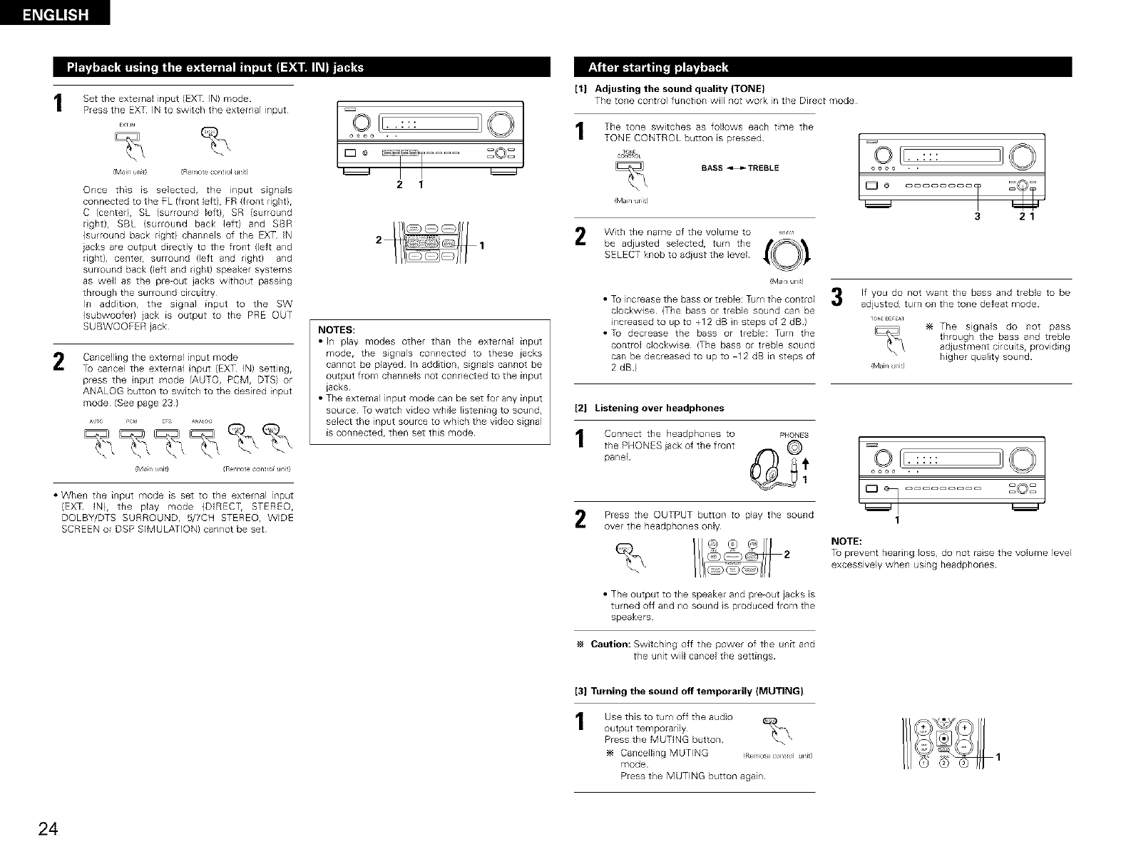
1Set the external input (EXT IN) mode
Press the EXT IN to switch the external input
EXTIN %
M_ir wl t_ (Rer_l_e control uni_)
Once this is selected, the input signals
connected to the PL (front left), PR )front right),
C (center), SL (surround left}, SR (surround
rght), SBL (surround back left) and SBR
)surround back right) channels of the EXT IN
jacks are output directly to the front {left and
right), center, surround left and right) and
surround back (left and rght) speaker systems
as well as the pre-out jacks without passing
through the surround circuitry
In addition, the signal input to the SW
(subwoofer) jack is output to the PRE OUT
SUBWOOFER jack
2Cancelling the external input mode
To cancel the external nput (EXT IN) setting,
press the nput mode (AUTO, PCM, DTS) or
ANALOG button to switch to the desired input
mode (See page 23)
{Man u/it) Re 1>te contro u/it)
• When the input mode is set to the external input
(EXT IN), the play mode {DIRECT, STEREO,
DQLBY/DTS SURROUND, 5/7CH STEREO, WIDE
SCREEN or DSP SIMULATION) cannot be set
CoL[°I =°=
2 1
NOTES:
•In play modes other than the external input
mode, the signals connected to these jacks
cannot be played In addition, signals cannot be
output from channels not connected to the input
iacks
• The external input mode can be set for any input
source Tu watch video while listening to sound,
select the input source to which the video signal
is connected, then set this mode
[1] Adjusting the sound quality (TONE)
The tone control function will not work in the Direct mode
The tone switches as follows each time the
TONE CONTROL button is pressed
BASS _TREBLE
Mdh Jr1)
With the name of the volume to ,,,_
be adjusted selected, turn the {0 !
SELECT knob to adiust the level
MJn Jni)
•Tu increase the bass or treble: Turn the control
clockwise (The bass or treble sound can be
increased toupto +12dB nstepsof 2dB)
• Tu decrease the bass or treble: Tdrn the
control clockwise (The bass or treble sound
can be decreased to up to -12 dB in steps of
2 dB)
COL-:::
oooo *
321
If you do not want the bass and treble to be
adjusted, turn o_ the to_e defeat mode
_oN__;FEAT
The signals do not pass
through the bass and treble
adjustment circuits, providi_g
higher quality sound
Mah /i)
[2] Listening over headphones
Connect the headphones to Pt4oN_s
the PHONESiackof the front @
panel Q_ _1
Press the OUTPUT button to play the sound
over the headphones only
• The output to the speaker and pre-out jacks is
turned off and no sound is produced from the
speakers
Caution: Switching off the power of the unit and
the unit wil cancel the settings
u_ _0_
I
NOTE:
To prevent hearing Joss, do not raise the volume level
excessively when using headphones
[3] Turning the sound off temporarily (MUTING}
Use this to turn off the audio
output temporarily
Press the MUTING button
Ca_cellng MUTING (Rerloecon_ol jni)
mode
Press the MUTING button again
24
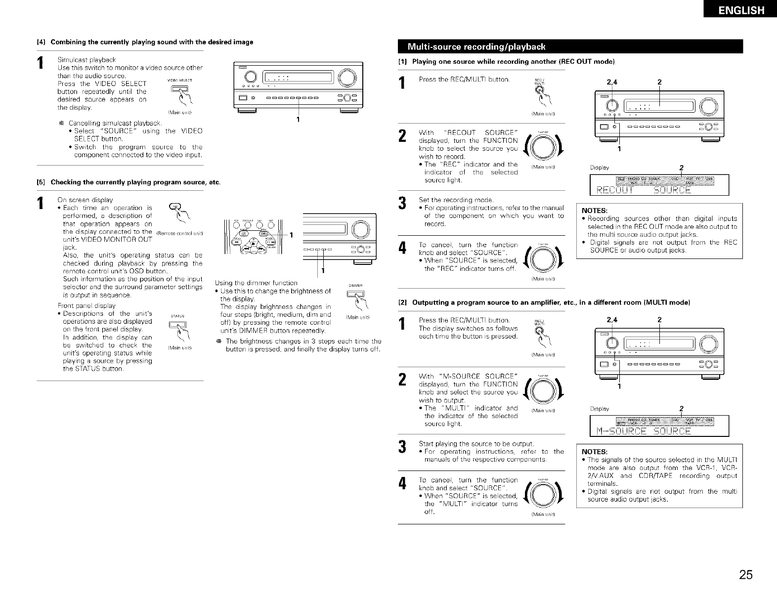
(4] Combining the currently playing sound with the desired image
Simulcast playback
Usetbisswitchtomorfitoravideosourceother /[_O' IF ]_ Q ]
than the audio source . . : : :
Press the VIDEO SELECT V,_EOS_LEC_ OOOO . .
button repeatedly until the b
desired sourceappearson _ o ZOZ
the display Mir un tl _
1
Cancelling simulcast playback
• Select "SOURCE" using the VDEO
SELECT button
• Switch the program source to the
component connected to the video input
[5] Checking the currently playing program source, etc.
On screen display
• Each time an operation is
performed, a description of
that operation appears on
tile display connected to the (RelYotecoltrol Jnit)
unit's VIDEO MONITOR OUT
jack
Also, the unit's operating status can be
checked during playback by pressing the
remote control unit's OSD button
Such information as the position of the input
selector and the surround parameter settings
is output in sequence
Front panel display
• Descriptions of the unit's ST_US
operations are also displayed
on the front panel display
In addition, the display can
be switched to check the (M_irurlt)
unit's operating status while
playing a source by pressing
the STATUS button
! _0_ ,
Using the dimmer fu,ctio, _,_,_
• Use this to change the brightness of
the display
The display brightness changes in
four steps/bright, medium, dim and (M_ir_nt)
off} by pressing the remote co_trol
unit's DIMMER button repeatedly
The bdghtness cha_ges i_ 3 steps each time the
butto_ is pressed, a_d finally the display turns off
[1] Playing one source while recording another (REC OUT mode)
Press the REC/MULTI button *;c
_ULTI
{M_in unit)
With "RECOUT SOURCE"
displayedr turn the FUNCTION
knob to select the source you
wish to record
• The "REC" ndicator and the iM_n Jnit)
indicator of the selected
source light
Set the record ng mode
• For operating nstructio_ls, refer to the mallual
of the component on which you want to
record
To cancel, turn the functo_
knob and select "SOURCE"
• When "SOURCE" is selected,
the "REC" indicator turns off
iMarl Jl_it)
2,4 2
I'1©
1
Display 2
i:;;:ii[[:C 0 UT :_i:::ii...iB:i'::E
NOTES:
• Recording sources other than digital inputs
selected in the REC OUT mode are also output to
the multi source audio output jacks
• Digital signals ale not output from the REC
SOURCE or audio output iacks
[2] Outputting a program source to an amplifier, etc., in a different room (MULTI mode)
Press the REC/MULTI button nEc
MU_TI
The display switches as follows
each time the button is pressed¸
{M_in unit)
With "M-SOURCE SOURCE"
displayed, turn the FUNCTION
knob and select the source you
wish to output
• The "MULTI" indicator and {ManJnit)
the indcator of the selected
source light
Start playing the source to be output
• For operating instructions, refer to the
manuals of the respect ve components
To cancel, turn the functon
knob and select "SOURCE"
• When "SOURCE" is selected,
the "MULTI" indicator turns
off iMar I Jl_it)
2,4 2
1
Display 2
I I
NOTES:
• The signals of the source selected in the MULTI
mode are also output from the VCRq, VCR-
2/VAUX and CDR/TAPE recording output
terminals
• Digital signals are not output from the mugi
source audio output jacks
25
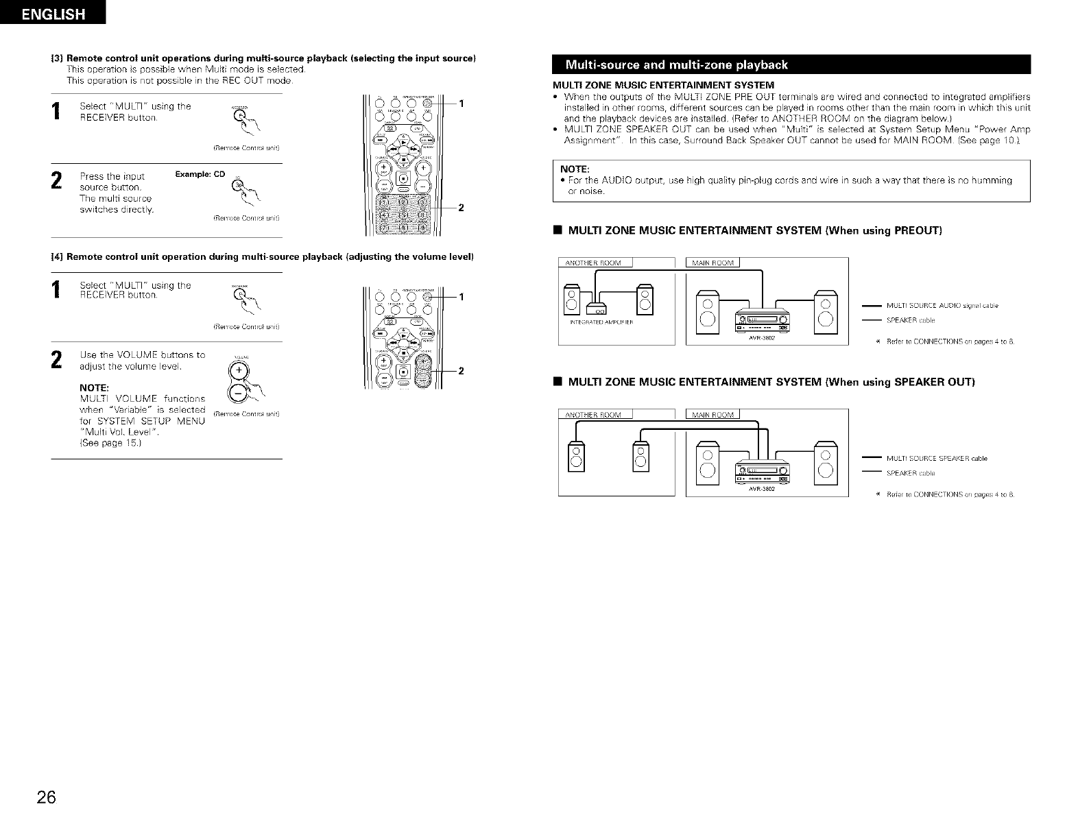
13] Remote control unit operations during multi-source playback (selecting the input source)
This operation s possible when Multi mode is selected
This operation is not possible in the REC OUT mode
hv_rri_ _I_ IIW__.'_ _
Select "MULTI" using the ......%
RECEIVER button
!RelY_c}:eContlo_uniti
Press the input Example: CD _
source button
The multi source
switches directly (RelTo:e Contlo u/i9
C%O0
O©O
14] Remote control unit operation during multi-source playback (adjusting the volume level)
Select "MULTI" using the ......(_\
RECEIVER button
!RelY_c}:e Contlo_ uniti
Use the VOLUME buttons to
adjust the volume level
NOTE:
MULTI VOLUME functions
when "Vadabb" is selected
for SYSTEM SETUP MENU
"Multi Vol Level"
(See page 1_)
(Remote Contlo} unit)
1
2
MULTI ZONE MUSIC ENTERTAINMENT SYSTEM
• When the outputs of the MULTI ZONE PRE OUT terminals are wired and connected to integrated am@if ers
installed in other roomsr different sources can be played in rooms other than the main room in which this unit
and the playback devices are installed )Refer to ANOTHER ROOM on the diagram below)
• MULTi ZONE SPEAKER OUT can be used when "Multi" is selected at System Setup Menu "Power Amp
AssigNmeNt" In this case, Surround Back Speaker OUT cannot be used for MAIN ROOM (See page 10)
NOTE:
• For the AUDIO output, use high quality pin-plug cords and wire in such a way that there is no humming
Or noise
•MULTI ZONE MUSIC ENTERTAINMENT SYSTEM (When using PREOUT}
AVR_3802
m MULTI SOURCE AUDK3 sigl_l came
-- SPEAKER cable
_ Re_e_ to CONNECTIONS on pages 4 _ 8
•MULTI ZONE MUSIC ENTERTAINMENT SYSTEM (When using SPEAKER OUT}
ANOTI IER ROOM I
AVR_3802
m MULTI SOURCE SPEAKER cable
-- SPEAKER cable
_ Re_e_ to CONNECTIONS on pages 4 _ 8
26
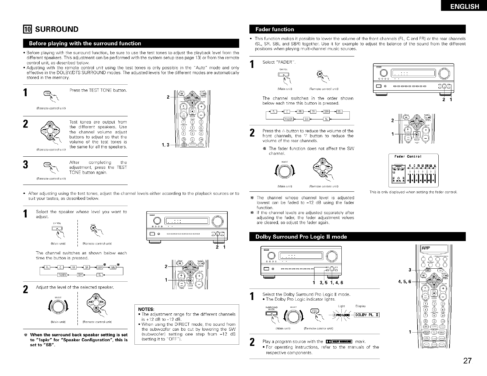
[] SURROUND
I:_ ,'J_r_lg _ I_
• Before playing with the sun }und function, be sure to use the test tones to adjust the playback level from the
different speakers This adjustment can be performed with the system setup (see page 13) or from the remote
control unit, as described below
• Adjusting with the remote control unit using the test tones is only possible in the "Auto" mode and only
effective in the DOLBY/DTS SURROUND modes The adiusted levels for the different modes are automatically
stored in the memory
Press the TEST TONE button
(Re_ lot e cot tlO! urlt!
Test tones are output from
the different speakers Use
the channel volume adjust
buttons to adiust so that the
volume of the test tones s
{Re/Iotec/r tlO!_nt) the same for all the speakers
After completing the
adjustment, press the TEST
TONE button again
(Re_ 1ore c _rrio! _rlt!
2
© @®
1,3
• After adjusting using the test tones, adjust the channel levels either according to the playback sources or to
suit your tastes, as described below
Select the speaker whose level you want to
adjust
The channel switches as shown below each
time the button is pressed
2 1
r_OEp 3_, 3.
2Adiust the level of the selected speaker
f[vllr u/J9 (Rem?e contto! urtl
When the surround back speaker setting is set
to "Ispkr" for "Speaker Configuration", this is
set to "SB".
NOTES:
• The adjustment range for the different channels
is +12 dB to -12 dB
• When using the DIRECT mode, the sound from
the subwoofer can be cut by Iowedng the SW
(subwoofer) setting one step from -12 dB
(setting it to "OFF"}
• This function makes it posT ble to lower the volume of the front channels (FL, C and FR) or the rear channels
(SL, SR, SBL and SBR) together Use it for example to adjust the balance of the sound from the different
positions when playing multEchannel music sources
Select "FADER"
c_vo
(Man Jl_it] (Rer tote CXtlO b/it/
The channel switches in the order shown
below each time this button is pressed
oooo . .
ID°
21
2Press the z button to reduce the volume of the
front channels, the 'button to reduce the
volume of the rear channels
_4 The fader function does not affect the SW
channel
(Man Jl_it] (Rer tote CXtlO b/it/
The channel whose channel level is adjusted
lowest can be faded to -12 dB using the fader
function
if the channel levels are adjusted separately after
adjusting the fader, the fader adjustment values
are cleared, so adjust the fader again
coo,to/JBiiii;T
_1T _1 T al T *lit *IITaT I T
= = i i i I i
This is only displayed w/en set[ing the fader control
[ T9}oIf: ::::
ID°
1 3,5 1,4,6
Select the Dolby Surround Pro Logic 1] mode
• The Dolby Pro Logc indicator lights
_ _,_ Ligh! Display
{B/lair1 u/it} {Rer tote cXitlO _/it/
Play a source with the nn_ mark
program
• For operating instructions, refer to the manuals of the
respective components
3
4,5,6
1
RHP
OOOO
(9 Q ®
q, @
©®®
27
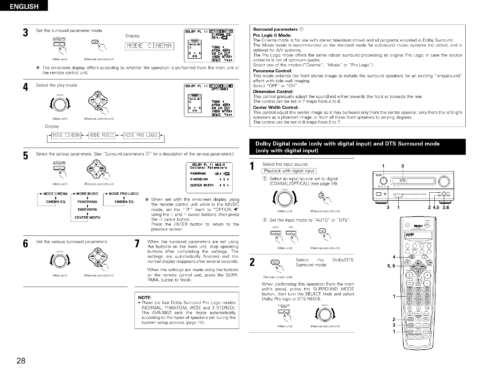
l_[=]]_l]ff
3
4
5
6
Set the surround parameter mode¸
Display
SURROUNU
I P'iOi[:,EC i NEP'iAI
imam u/iti iRemot ec _r tic! unt!
II CIN Q.
_4
TONE4 I
AFOM4_
SB ¢H OUT
4N_ MTRX_
_ Yes4
The on-screen display differs according to whether the operation is performed from the main unit or
the remote co_trol unit
Select the play mode
imam u]it) (Re_ iote c _rtic! unt!
Display
I I OPTIONS4
TONE4
SB CH OUT
4NONMTRX_
Yes4
Select the var ous parameters (See "Surround parameters ]" for a description of the various parameters)
SURROUN_
%
iM_ln u/it) iRe+lore c)rtlO! _nt)
AEQ |PANO_RAMA _MAEQ
LC_ WIDTH
COLBY PL II MUSIC
Optional Perimeter=
PANOP_ _4:k_
DIMENSION 43_
CENTER WIDTH 40_
_+ Whe_ set with the on-screen display usi_g
the remote control unit while n the MUSIC
mode, set the " _ " mark to "OPTION <"
using the, and ' cursor buttons, then press
the cursor button
Press the ENTER button to return to the
previous screen¸
Set the var ous surround parameters
imam u]it) (Re_ _ote c _rtic! tmt)
7When the surround parameters are set using
the butto_s on the main unit, stop operat ng
buttons after completing the settings The
settings are automatically finalized and the
normal display reappears after several seconds
When the setti_gs are made using the buttons
o+1the remote co_trol u{]it, press the SURR
PARA button to finish
NOTE:
•There are four Dolby Sulround Pro Logic modes
{NORMAL, PHANTOM, WIDE and 3 STEREO)
The AVR-3802 sets the mode automatically
accord ng to the types of speakers set during the
system setup process (page 10)
Surround parameters _l
Pro Logic 1! Mode:
The Cinema mode is for use with stereo television shows and all programs encoded i+_Dolby Surround
The Music mode is recomme+_ded as the standard mode for autosou+_d music systems /no video), and is
optio+_al for AN systems
The Pro Logic mode offers the same robust surround processing as odgi+_al Pro Logic in case the source
contents is not of optimum quality
Select one of the modes ("Cinema", "Music" or "Pro Log c")
Panorama Control:
This mode extends the front stereo image to include the surround speakers for an exciting "wraparound"
effect with side wall imaging
Select "OFF" or "ON"
Dimension Control:
This control gradually adiust the soundfield either towards the front or towards the rear
The control can be set n7 steps fromoto6
Center Width Control:
This control adjust the center image so it may be heard only from the center speaker; only from the left/right
speakers as a phontorn image; or from a]l three fro+_t speakers to varyi+_g degrees
The control can be set in 8 steps from O to 7
2
Select the i_put source
[ Playback with digital input ]
,_1_Select a_ i_put source set to d gital
(COAXIAL/OPTICAL} (see page 14)
iM_n Jnitl !Rerlo _ CLan rol urit)
,2,= Set the input mode to "AUTO" or "DTS"
_uo ,s
iM_n Jnitl !Rerl? _ con _?1 urlt)
Select the Doiby/DTS
Surround mode
(Remote contro+ u+fit)
Whe++ performing this operatic++ from the main
unit's pa++el, press the SURROUND MODE
button, then turn the SELECT knob and select
Dolby Pro logic or DTS NEO:6
mO_E
1 3
3 1 2 4,5 2,6
28
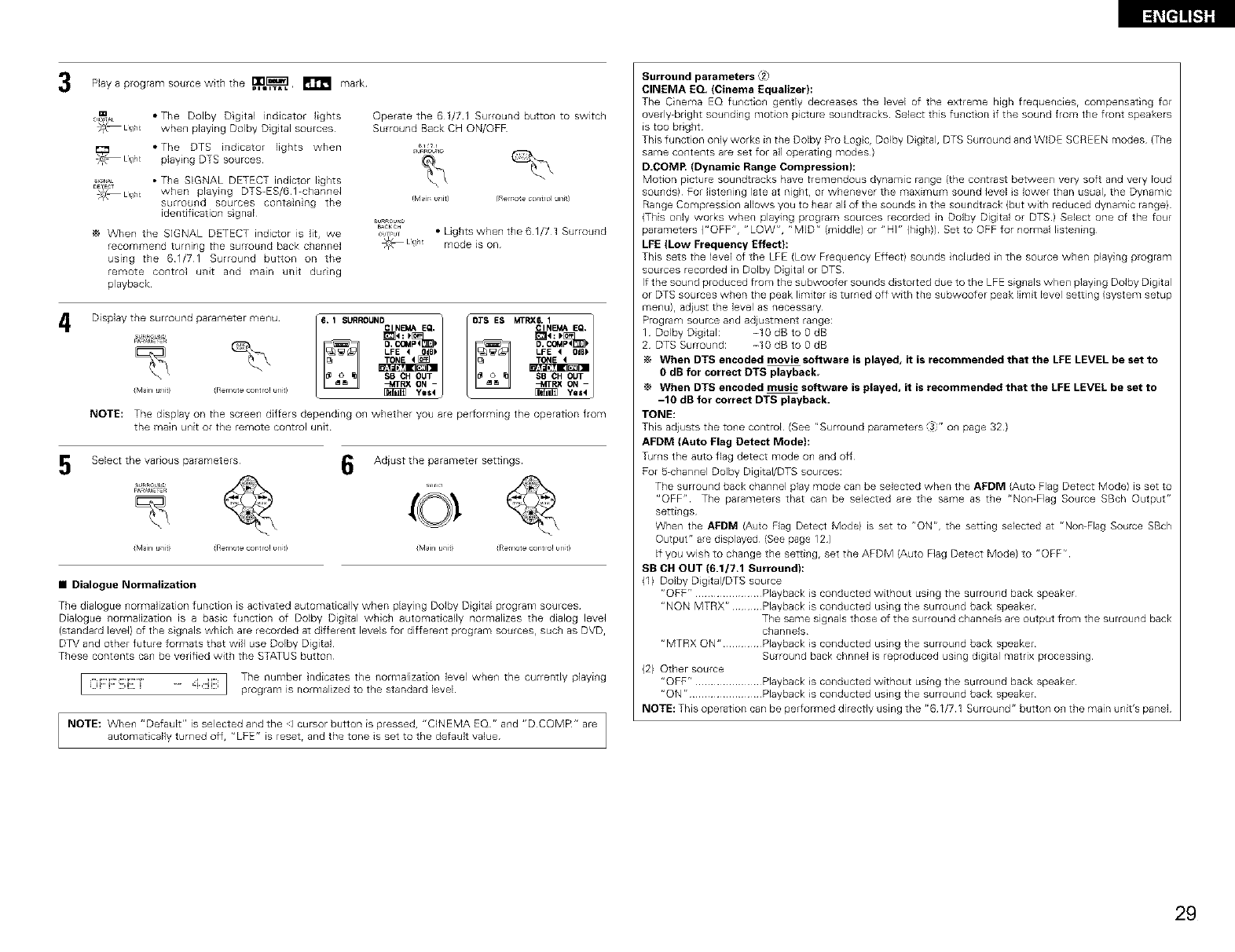
3
4
5
Play a program source with the w_],Ii_, _ mark
• The Dolby Digital indicator lights
whe_ playing Dolby Dig tal sources
Operate the 61/71 Surround butto_ to switch
Surround Back CH ON/OFF
• The DTS indicator lights when _k_#_
"C{, Llg/t playing DTS sources _,_'_
• The SIGNAL DETECT indictor lights
legAL
DE_EC_
_O_ Ll!//t when playing DTS-ES/61-channel
surround sources containing the trvllr u/it/ RelY°tec°ltr°l]ni)
identification sgnal
When the SIGNAL DETECT indictor is lit, we
recomme_d turning the surrou_d back channel
using the 61/71 Surround button on the
remote control unit and main unit during
playback
su_Rou_
_CKC_
_,,_ • Lights when the 61/71 Surround
_ Llg/t mode is on
Display the surround parametermenUsuRRouNu / 6. 1SURROUNDcl NEMA E_I]_--_1 _40.COMP4_:_ " [OTS ES MTP'Xc6"I1NI_A E(a"1_ _4D.C_,tP<_:I*
SB CH OUT SB CH OUT
-MTRX ON - --MTRX ON -
(IVl_n ufiti (Re 1ore _rtlo! _nt! _ Yes _ L _ yIIS4J
NOTE: The display on the scree_ differs depending o_ whether you are peHorming the operation from
the main unit or the remote control unit
Select the various parameters 6Adiust the parameter settings
SURROUNd
%
(Main u/iti (Remote c_rtlo! unt! (Main u/iti (Remote c_rtlo! unt!
• Dialogue Normalization
The dialogue normalization function is activated automatically when playing Dolby D gital program sources
Dialogue normalization is a basic function of Dolby Digtal which automatically normalizes the dialog level
{standard bye1) of the signals which are recorded at d fferent levels for different program sources, such as DVD,
DTV and other future formats that will use Dolby Digi[al
These contents can be verified with the STATUS button
................................... I The number ndicates the normalization level when the currently playing
i i..,i. ..... ,:i ,.ii._ program is normalized to the standard level
NOTE: Whe_ "Default" is selected and the ]cursor button is pressed, "CINEMA EQ" and "DCOMR" are
automatically turned off, "LFE" is reset, and the tone is set to the default value
Surround parameters _2
CINEMA EQ, (Cinema Equalizer):
The Cinema EQ fu_ctio_ gently decreases the level of the extreme high freque_c_es rc_r_per_sat_r_g f_
ovedy_bright sou_di_g motion picture soundtracks Select this fu_ct on if the sound from the front speakers
is too bright
This function only works i_]the Dolby Pro Logc, Dolby Dig tal, DTS Surround and WIDE SCREEN modes (The
same contents are set for all operating modes)
D.COMP, (Dynamic Range Compression):
Motion picture soundtracks have tremendous dynamic ra_]ge (the co_]trast between ve Wsoft and very loud
sounds) For listening late at night, or whenever the maximum sound level s lower than usual, the Dynamic
Range Compression allows you to hear all of the sounds n the soundtrack (but with reduced dynamic range)
(This only works when playing program sources recorded in Dolby Digilal or DTS) Select one of the four
parameters {"OFF", "LOW", "MID" {middle) or "Hi" {high)) Set to OFF for normal listening
LFE (Low Frequency Effect}:
This sets the level of the LFE (Low Frequency Effect) sounds included i_ the source when playing program
sources recorded in Dolby Digital or DTS
If the sound produced from the subwoofer sounds distorted due to the LPE signals when playing Dolby Digital
or DTS sources when the peak limiter is turned off with the subwoofer peak limit level setting {system setup
menu)r adiust the level as necessary
Program source and adjustment range:
1 Dolby Digtal: -10 dB to g dB
2 DTS Surround: -lg dB to gdB
When DTS encoded movie software is played, it is recommended that the LEE LEVEL be set to
0 dB for correct DTS playback
When DTS encoded music software is played, it is recommended that the LFE LEVEL be set to
-10 dB for correct DTS playback.
TONE:
This adjusts the to_e control (See "Surround parameters _'" o_ page 32)
AFDM (Auto Flag Detect Mode):
Turns the auto flag detect mode o_ and off
For _chan_el Dolby Digital/DTS sources:
The surround back channel play mode can be selected when the AFDM {Auto Flag Detect Mode) is set to
"OFF" The parameters that can be selected are the same as the "Non-Flag Source SBch Output"
settings
When the AFDM (A_to Fag Detect Model is set to "ON", the setting selected at "Non-Flag Source SBch
Output" are displayed (See page 12)
If you wish to change the setting, set the APDM {Auto Flag Detect Model to "OFFr'
SB CH OUT (6.1/7.1 Surround):
(1) Dolby Digtal/DTS source
"OFF" ..................... Playback is conducted without using the surround back speaker
"NON MTRX r' ......... Playback is conducted using the surround back speaker
The same signals those of the surround channels are output from the surround back
channels
"MTRX ON" ............ Playback is conducted using the surround back speaker
Surround back chnnel is reproduced using digital matrix processing
(2) Other source
"OFF" ..................... Playback is conducted without using the surround back speaker
"ON" ....................... Playback is conducted using the surround back speaker
NOTE: This operation can be performed directly using the "61/71 Surround" button on the main unit's panel
29
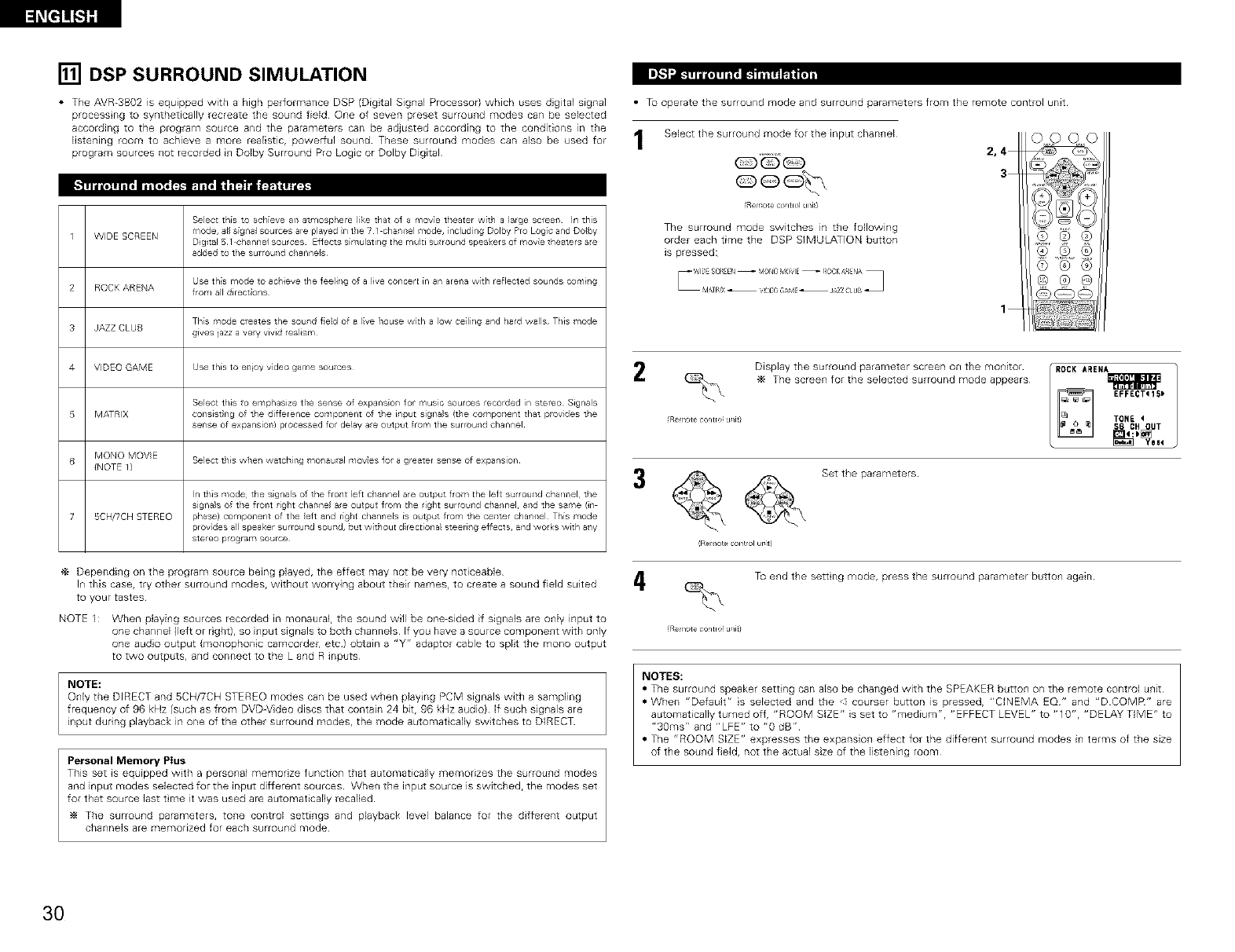
[] DSP SURROUND SIMULATION
• The AVR-3802 is equipped with a high performance DSP (Digtal Signal Processor} which uses digita) signal
process ng to synthetically recreate the sound field One of seven preset surround modes can be selected
according to the program source and the parameters can be adjusted according to the conditions in the
listening room to achieve a more rea)istic, power[ul sound These surround modes can also be used for
program sources not recorded in Dolby Surround Pro Logic or Dolby Digital
Select this to achieve an atmosphere like that of a move theater with a large streets Irl this
1 WIDE SCREEN mode, a_ls[gna_ sources are played _nthe 71 c(lanllel i/lode, including Dolby Pro Logic and Dolby
Digital 5 1 chanr/el Sou/ces Zfiects simulatil/g the r qu_ti sulrour/d speal<ers of movie theaters ale
added to the surrou4d channels
Use this mode to ac_/Jeve the leelJ4g of a live echoer €[n an aref_a with reflected sounds eomJ4g
2 ROCK ARENA from all direct;ons
This mode creates the sound f;eld of a live house with a low ceilil/g and hard walls¸ This mode
3 JAZZ CLUB gives jazz a very vivid realism
4 VIDEO GAME Use this to el/icy v_deo game sources¸
Select this to emphasize the sense of expansion/ for music sources recorded in stereo SJg_/als
5 MATRIX consist}ng of the difference compol/ent of the input signals (the cor_lpoTlent that provides the
sense of expansiof_l processed lo_ delay a_e output from the surrou4d channel
6 MONO MOVIE Select this w_lel/watctlirlg tool/aural movies lot a greater sense of expar/slor/
(NOTE 1)
In this mode the s gnals of the frollt ]eft c/ar/nel are output from the left surround channel, the
slgr/a s of the froflt right charme are output from the right surround ctlan_lel, a;ld the same (in
2 5CH/TCH STEREO phase) compollent of the eft and right c/annels [s output from the cellter channel This mode
provides al speaker surrouTld souTld, but w[ti/out d rectiona_ steeri/g eflects, and woks with a/y
stereo program source
Depending on the program source being played, the effect may not be very noticeable
In this case, try other surround modes, without worrying about their names, to create a sound field suited
to your tastes
NOTE 1 : When playing sources recorded in monaural, the sound will be one-sided if signals are only input to
one channel ()eft or right), so input signals to both channels If you have a source component with only
one audo output (monophonic camcorder, etc) obtain a "Y" adaptor cable to split the mono output
to two outputs, and connect to the L and R inputs
NOTE:
Only the DIRECT and SCH/TCH STEREO modes can be used when playing PCM signals with a sampling
freque_lcy of 96 kHz (such as from DVDWideo discs that contain 24 bit, 96 kHz audio} If such sig_lals are
input during playback in one of the other surround modes, the mode automat cally switches to DIRECT
Personal Memory Plus
This set is equipped with a personal memorize function] that automatical)y memorizes the surrou_]d modes
and input modes selected for the input different sources When the input source is switched, the modes set
for that source last tme it was used are automaticaNy recalled
The surrou_d parameters, to_e control setti_gs and playback level balance for the different output
cbannels are memorized for each surround mode
• Tu operate the surround mode and surround parameters from the remote control unit
Select the surround mode for the input chan_el 2,4
3
(Remoteco_ltrolunit)
The surround mode switches in the following
order each time the DSP SIMULATION button
is pressed:
1
OOOO
Display the surround parameter screen on the monitor IROCK AREN_The screen for the selected surround mode appears
EFFECT<15_
Re _>te contro u/i9 TON_
.0u,
_ @_ Set the parameters
(Rer _o e COl_{ol urit)
To end the sett ng mode, press the surround parameter butto_ again
Re 1>te contro u/it)
NOTES:
• The surround speaker setting can also be changed wiLb the SPEAKER button on the remote control u_it
• When "Default" s selected and tile courser button is pressed, "CINEMA EQ" and "D COMR" are
automatically turned off, "ROOM SIZE" is set to "medium", "EFFECT LEVEL" to "10", "DELAY TIME" to
"3gins" and "LFE" to "g dB"
• The "ROOM SIZE" expresses the expansio_ effect for the different surround modes i_ terms of the size
of the sou_d fie)d, not the actual size of the listening room
3O
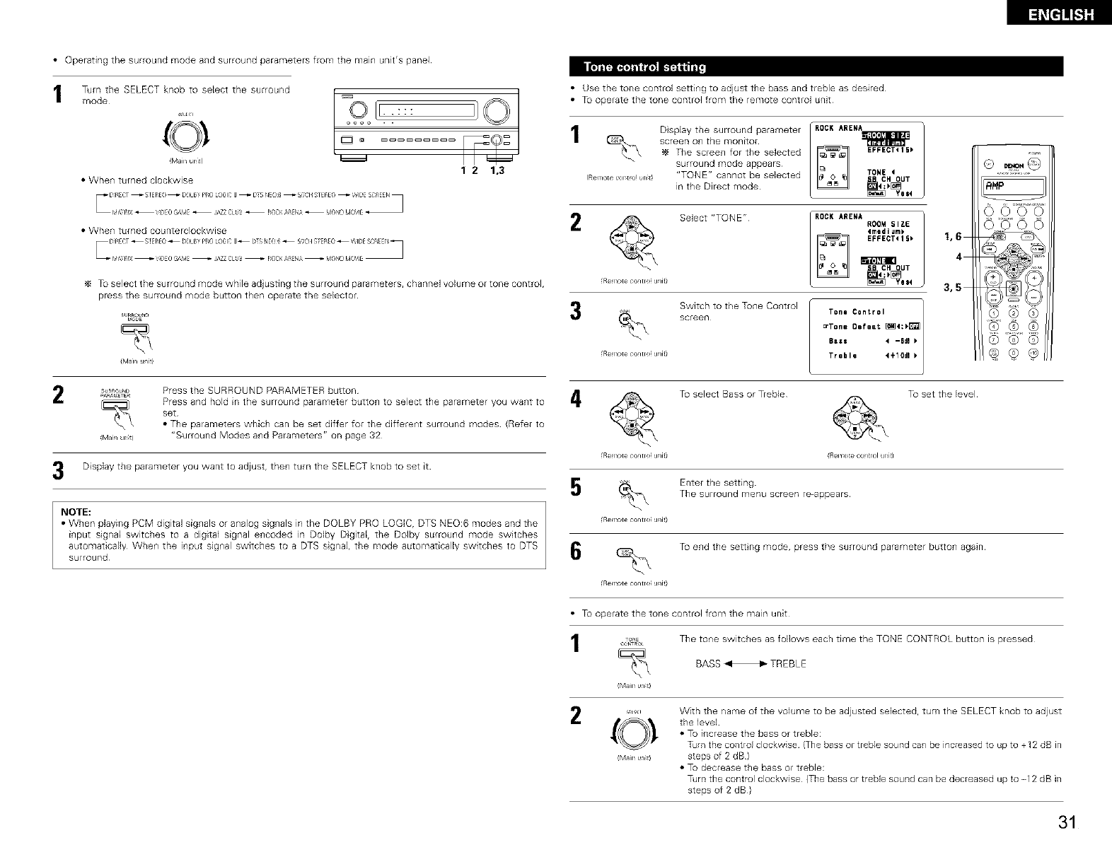
• Operating the surround mode and surround parameters from the main unit's panel
Trim the SELECT knob to select the surround
mode
!Main umtl
• Whe_l turned clockwise
oooo . .
°
1 2 1,3
• When turned counterclockwise
Tu select the surround mode while ad}usting the surround parameters, channel volume or tone control,
press the surround mode button then operate the selector
_,_E
(Main uniti
_ou_ Press the SURROUND PARAMETER button
_A_tTE E_
_\ Press and hold in the surround parameter button to select the parameter you want to
set
• The parameters which can be set differ for the different surround modes (Refer to
Mail jnt) "Surround Modes and Parameters" on page 32
Display the parameter you want to adjust, then turn the SELECT knob to set it
NOTE:
•When playing PCM digital sig_lals or a_lalog sig_lals in the DOLBY PRO LOGIC rDTS _O_6 r_d_s _r_d the
i_lput signal switches to a digital signal e_lcoded in Dolby Dgital, the Dolby surround mode switches
automatically Whe_ the input sig_al switches to a DTS sgnal, the mode automatically switches to DTS
surround
• Use the tone control setti_g to adjust the bass and treble as desired
• Tu operate the tone control from the remote control unit
2
IRe_note_x_r_tro!_n_tI
D splay the surround parameter
screen on the n_lonitor
The screen for the selected
surround mode appears
"TONE" cannot be selected
in the Direct mode
Remote controF uniti
Select "TONE"
ROCKARENA
EFFECTtI5_
TONE4
Switch to the Tone Co_trol
screen
4
ROCK ARENA ROOM SIZE
4medium)
EFFECT415_
Tone Centrol J
ErTone ORfeat _4:_
8a_s 4 -6d0
Treble t÷lOdl F
Remote contro_ unit)
1,6
4
3,5
To select Bass or Treble To set the level
RHP
Q,Q,9
(Z) ® ®
Remote contro_ uniti (Remote control unit)
Enter the setting
The surround menu screen re-appears
Re _>te contro u/i9
To end the sett ng mode, press the surround parameter button again
Re _>te contro u/i9
•T_ operate the tone control from the main unit
_o_ The tone switches as follows each time the TONE CONTROL button is pressed
BASS m TREBLE
(Main untl
,-, With the name of the volume to be adjusted selected, turn the SELECT knob to adjust
(O! the Jevel
• To increase the bass or treble:
Tam the contro clockw se {The bass or treble sound can be increased to up to +12 dB in
!MainUrlt) steps of 2 dB)
• To decrease the bass or treble:
Tdrn the control clockwise (The bass or trebb sound can be decreased up to -12 dB in
steps of 2 dB)
31
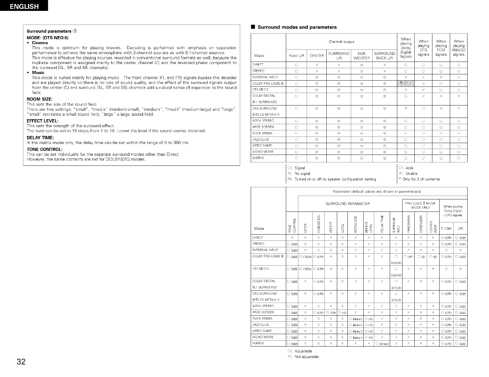
l_[=]]_S]g
Surround parameters
MODE: (DTS NEO:6)
• Cinema
Tffis mode is optimum for playing movies Decoding is per;ormed with emphasis on separaton
perfomnance to achieve the same atmosphere with 2-channel sources as with 6 1-cnar_nel sources
This mode is effective for playing sources recorded in conventional surround formats as weN, because the
in-phase component is assigned mainly to the center channel (C) and the reversed phase component to
the surround (SL, SR and SB channels)
• Music
This mode s suited mainly for playing music The front channeJ (FL and FR) sgnals bypass the decoder
and are played directly so there is no loss of sound quality, and the effect of the surround signals output
from the center (C) and surround (SL, SR and SB) channels add a natural sense of expansion to the sound
field
ROOM SIZE:
This sets the size of the sound field
There are five settings: "small"r "med s" (medium-small), "medium", "med I" (medium-large) and "large"
r'small" recreates a small sound field, "large" a large sound field
EFFECT LEVEL:
This sets the strength of the surround effect
The level can be set in 15 steps from I to 15 Lower the level if the sound seems distorted
DELAY TIME:
In the matri× mode only, the delay time can be set within the range of g to 3gg ms
TONE CONTROL:
This can be set individually for the separate surround modes other than Direct
Howeve{, the same contents are set for DOLBY/DTS modes
32
•Surround modes and parameters
Mode
DIRECT
STERE()
EXTERNAL INPLT
DOLBY PRO LOGIC ]]
DTS NEO6
DOLBY DIGITAL
(6 I SURROUND)
DTS SURROUND
(DTS ES MTRX 6 /)
_TCH _EREO
WIDE SCREEN
ROCK ASENA
JAZZ CLUB
VIDE(} GAME
MONO MOVIE
MATRIX
Mode
DIRECT
STERE()
EXTERNAL INPLT
DOLBY PRO LOGIC ]]
When When When When
Channeloutput playing playing playing playirlg
Dolby DTS PCM ANAOG
SURROUND SUB SURROUND Digital signals signals signals
Frol/t L/R CENTER L/R WOOFER BACK L/R Signals
( x x (i ( } i
( x x (i ( } i
_) x x )
C _ (i x >
C _ ( x >
(2 _ (i ( } i
(2 _ (i ( } i
( _ (i ( } i
( _ (i ( } i
( _ (i ( } i
( _ (i ( } i
( _ (i ( } i
: NO sigllal
Tumed oil or of r_y speaker configuration/ setting
Parameter (defaul values are shown in pare_/theses)
SURROUND PARAMETER
8 _-
> >
> >
> >
PRO LOGIC 1I MUSIC
M©DE ON_ WheTI p_a'/_ng
DOllw Digital
/DTS s_gnals
<
• o D C0NP LFE
> X X ( (OFF ( (0dB
( (0dB X X ( (OFF ( (0dB
( (0dB X X > >
( (0dB X X (} OFF (} (3) (} (0/ ( (OFF ( (0dB
pY _8
DTS NEE}(> ( (0dB ( ,E_: (eFF) x x ///(} />¢ >¢
pY _8
DOLBY DIGIT_', ( (0dB >¢ (eFF) x x ///(} /( (OFF ( (0dB
(6 I SL R_qOUND) V-X0
DTS SLRROUND ( (0dB >¢ (eFF) x x ///(} /( (OFF ( (0dB
(DTS ES MTRX 6 /) V-XOi
b/TEbl %-EREO ( (0dB >¢ >¢ X X / / / / / ( (OFF ( (0dB
WIDE SCREEN ( (0dB >¢ (eFF) O ON} } /0 / / / / / ( (OFF ( (0dB
ROCK ARENA ( (0dB >¢ >¢ x x O [_e_u (}(18 / / / ((OFF ( (0dB
JAZZ CLL B ( (0dB >¢ >¢ x x O [_e_u (}(18 / / / ((OFF ( (0dB
VIDEO GAME ( (0dB >¢ >¢ x x O [_e_u (}(18 / / / ((OFF ( (0dB
MQNO MOVIE ( (0dB >¢ >¢ X X O [_e_u (} (18 / / / ( (OFF ( (0dB
MA-RX ( (0dB >¢ >¢ X X / / O 60 sac} / / ( (OFF ( (0dB
k_: Ad ustable
X Not adustable
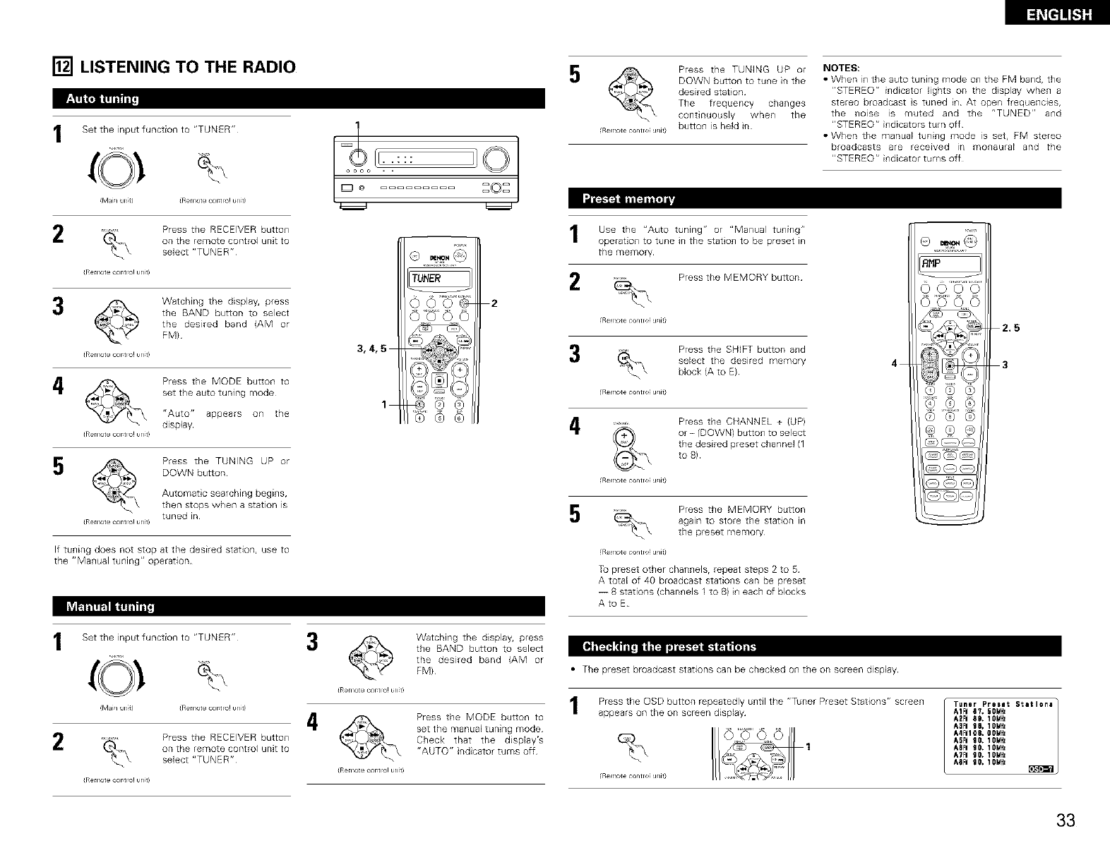
[] LISTENING TO THE RADIO
Set the input function to "TUNER"
M]J/ Jl_) (Remote c_r tlO! urlt/
2
(Remote cor_tlo! unit!
Press the RECEIVER button
on the remote control unit to
select "TUNER"
_ Watching the display, press
the BAND button to select
the desired band (AM or
FM}
(Remote cor_tlO! url_t !
4
(Remote coterie! unit!
Press the MODE button to
set the auto tuning mode
"Auto" appears on the
display
5
(Remote coterie! unit!
Press the TUNING UP or
DOWN button
Automatic searching begins,
then stops when a station is
tuned in
If tuning does not stop at the desired station, use to
the "Manual tuning" operation
1
l Ir:::
oooo . .
TUNER
2
3,4,5
1_,ee® ®
Press the TUNING UP or
DOWN button to tune in the
desired station
The frequency changes
continuously when the
Re _/tecentreu/iti button is held in
I_t'l
Use the "Auto tuning" or "Manual tuning"
operation to tune in the stat oN to be preset in
the memory
Press the MEMORY button
Re,He centre u/J9
Press the SHIFT button and
select the desired memory
block (A to E}
Re,He centre u/J9
i_ .......... Press the CHANNEL + (UP)
or - (DOWN) button to select
the desired preset channel (1
to 8)
Re,He centre u/J9
Press the MEMORY button
again to store the station _n
the preset memory
(Remote centre; uniti
Tu preset other channels, repeat steps 2 to 5
A total of 40 broadcast stations can be preset
-- 8 stations (channels 1 to 81 in each of blocks
Ate E
NOTES:
•When in the auto tuning mode on the FM band, the
"STEREO" indicator lights on the display when a
steEeo broadcast s tuned in At open frequenaes,
the noise is muted and the "TUNED" and
"STEREO" indicators turn off
• When the manual tuning mode is set, FM stereo
broadcasts are received Irt monaural and the
"STEREO" indicator turns off
A_P
0000
2,5
4 3
®®®
®®®
6o ® ®
Set the input function to "TUNER"
M]J/ Jl_) (Refrlote c_r tlO! urlt/
Press the RECEIVER button
on the remote control unit to
select "TUNER"
(Refrlot e c _r tlO! urlt!
3
4
©
(Remote cor_tlo! unit!
Watching the displa% press
the BAND button to select
the desired band (AM or
FM}
(Remote c{mtlO! unit!
Press the MODE button to
setthe manualtuning mode
Check that the dis@ay's
"AUTO"indicatorturns off
• The preset broadcast stations can be checked on the on screen display
Pressthe OSD button repeatedly untilthe "Tuner Preset Stations" screen
appears on the on screen display
(Remote centre; unit)
Tuner Presel Sletlens
A1FI 87. 50MHz
A2FI 8D. IOMHz
A3FI g6. IOMHz
A4FNI08, OOiHz
ASFI 90. IONHI
ASFI 90. 10MHz
A?FNB0. 10MHI
ASFI 90. 10NHz
33
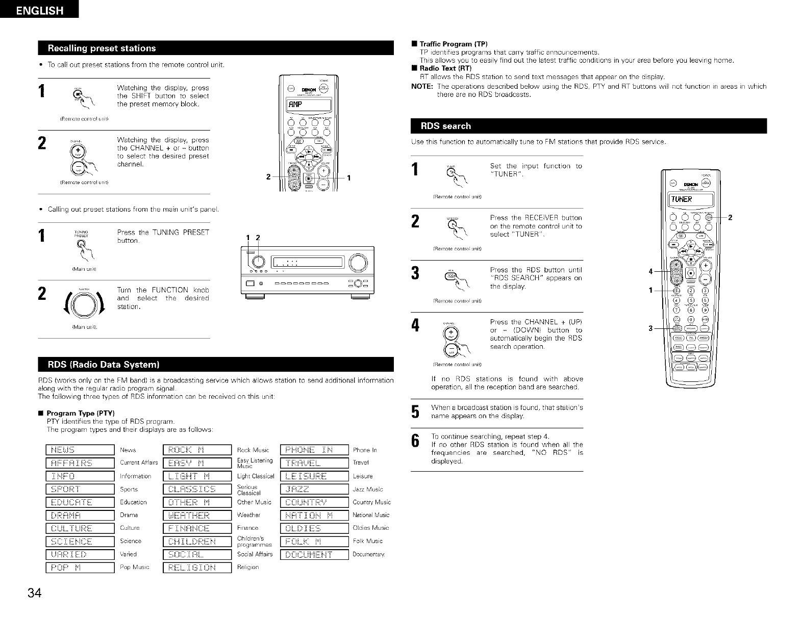
•Tu call out preset stations from the remote control unit
Watching the display, press
the SHIFT button to select
the preset memory block
iRemote coBtlo! un_
2........ Watching the display, press
the CHANNEL + or -button
to select the desired preset
channel
{Re_iote c _rtlO!un 2
AHP
1
• Calling out preset stations from the main unit's panel
I _,_ Press the TUNING PRESET
M_J/ Jnb _ , .
:©:
2{O_, Turn the FUNCTION knob
and select the desired _
stat on
(Maim unit)
RDS (works only on the FM band) is a broadcasting service which allows station to send additional information
along with the regular radio program signal
The following three types of RDS information can be received on this unit:
• Program Type (PTY)
PTY identifies the type of RDS program
The program types and their displays are as follows:
i':i:::_,E::::: INews [ [;[:(}Ci::: i'i ] Rock Music [ [::'i}Oi_E :[ i_: ] Phone n
::::::::::::::::::::::::: ICurrentAffai,s [ E::i::E::]:'i i'i ] MusicEaWListening[ i-i;;3::iiiE i.... ] Travel
:_:}}_;:::::, iIr/f°lr'lati°'/ [ [ ][_i]iii"i H ] hghtClasscal [ [ [][:]::[;:;}i[]i:E ] Leisure
:::::i::'om I spo,s :c:n::::;s::cs ] Serous [ ]JozzM. o
Class ca1
::::::::::::::::::::::::: IEducat°r/ [ {:)"iiii:::R H] Other Music ] COut/t'¥Musc
e::,Ri'inR IDrama [ J,i[][:i::i['i}i::]:i:_: ] Weathe [ i_:i::_]':[Oii i'i ] NatiopalM sic
CiU TiU::::i::: ICultue [ F::[iii::Jl}C[]: ] Fi....... [ {:)[ i]) :i][:[:::]]: ] OdesMus/c
:i[i;C]:EHCi[i: I Science [ :]:::i}]:i.[::,i:;]:i[i:_ ] Children's .........
"i:::,R:_:[][:_::, iVaried [ :_[_:_]::__Z:::_]_:::__.... ]Socia Affais [ [X:}Ciii,}i:Zi_"i ] Docvmena'y
F:'{:}i::' i'} I Pop Music [ i;:Ei, :[ {ili[ 0[_: ] Religio/
•Traffic Program (TP)
TP identifies programs that calry traffic announcements
This allows you to easily find out the latest traffic conditions in your area before you leaving home
•Radio Text (RT}
RT allows the RDS station to send text messages that appear on the display
NOTE: The operations described below using the RDS, PTY and RT buttons will not function in areas in which
there are no RDS broadcasts
Use this funct on to automatically tune to FM stations that provide RDS service
Set the input function to
"TUNER"
(Remote control uait)
Press the RECEIVER button
on the remote control unit to
select "TUNER"
Re _>tecormo u/J9
Press the RDS button until
"RDS SEARCH" appears on
the display
Re _>tecormo u/J9
i_ .......... Press the CHANNEL + (UP)
or - (DOWN) button to
automatically begin the RDS
search operation
Re _>tecontro ufi9
If no RDS stations is found with above
operation, all the reception band are searched
5When a broadcast station is found, that station's
name appears on the display
To continue searching, repeat step 4
If no other RDS station is found when all the
frequencies are searched, "NO RDS" is
displayed
TUNER
4
1 _i @@
3
2
34
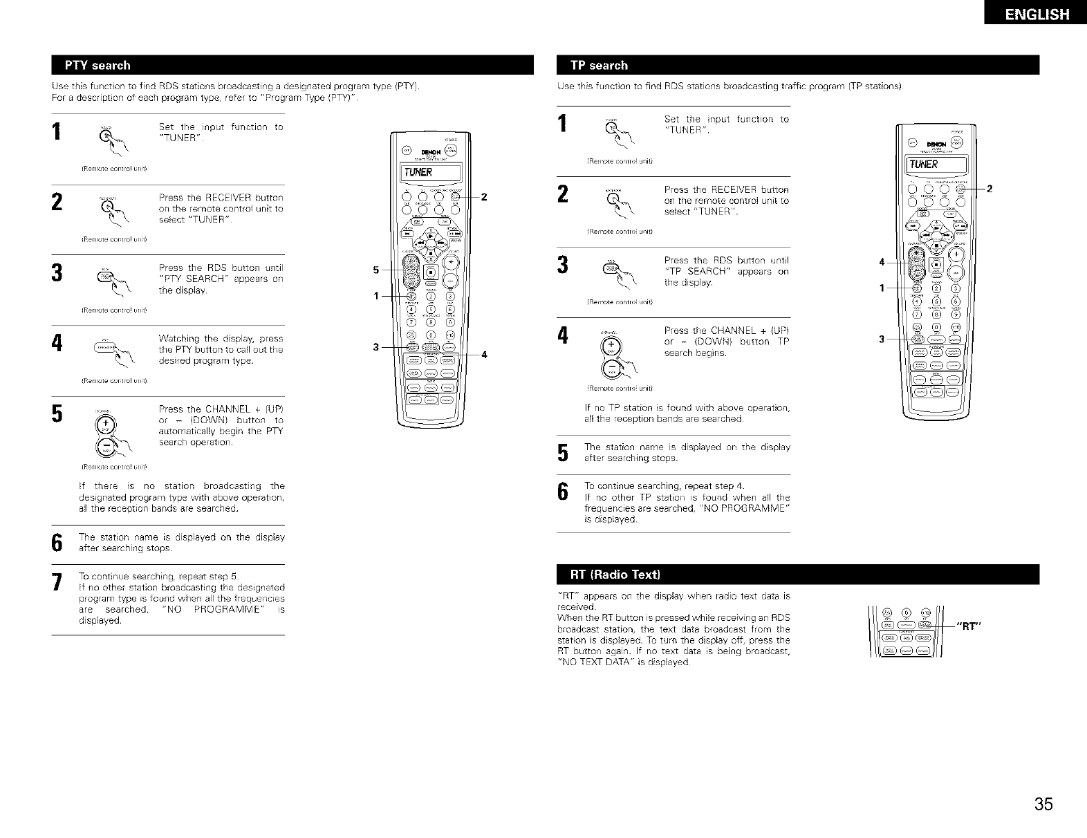
Use this function to find ADS stations broadcasting a designated program type (PTY)
For a descript on of each program type, refer to "Program Type (PTY)"
Set the input function to
"TUNER"
(Remote cor_tlO!wl_
2 Press the RECEIVER button
on the remote control unit to
select "TUNER"
(Re_1ore_ur rio! bn
Press the RDS button U_ltil
"PTY SEARCH" appears on
the display
(Re_1ore_ur rio! bn
5
1
4Watching the display, press
the PTY button to call out the 3
desired program type
g
(Remote cor_tlO! un_
........ Press the CHANNEL + {UP)
or - {DOWN) button to
automatically begin the PTY
searcll operatioll
(Remote c _r tlO! url
If there is no station broadcasting the
designated program type with above operation,
all the reception bands are searched
TUHER
©®@
@@
@@@
The station name is displayed on the display
after searching stops
7 To continue searching, repeat step 5
If no other station broadcasting the designated
program type is found when all the frequencEes
are searched, "NO PROGRAMME" is
displayed
2
Use this funct on to find RDS stations broadcasting traffic program (TP stations)
1Set the nput function to
"TUNER"
R_ _>te contro u/J9
Press the RECEIVER button
on the remote control unit to
select "TUNER"
Re _>te contro u/J9
Press the RDS button until
"TP SEARCH" appears on
the display
Re _>te contro u/J9
Press the CHANNEL + (UP)
or - {DOWN) button TP
search begns
If no TP station is found with above operat on,
all the reception bands are searched
5The station name is displayed on the display
after searching stops
6To continue searching, repeat step 4
If no other TP staton is found when all the
frequencies are searched, "NO PROGRAMME"
is displayed
TUHER
4
6_
3
I-'Jl [|-'_ tr_i I'_T_]
"RT" appears on the display when radio text data is
received
Whe_l the RT button is pressed while receivi_lg a_l RDS
broadcast station, the text data broadcast from the
station is displayed Tu turn the display off, press the
RT button1 again If no text data is being broadcast,
"NO TEXT DATA" is displayed
2
35
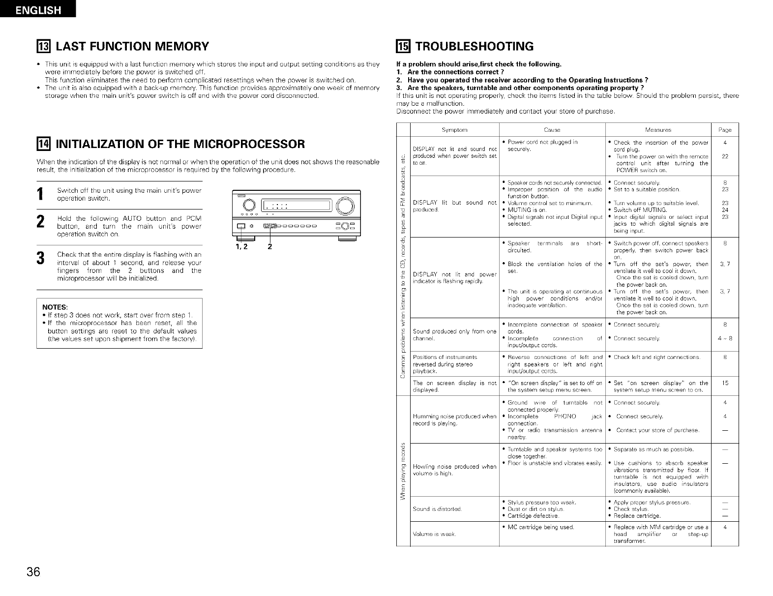
[] LAST FUNCTION MEMORY
• This unit is equipped with a last function memory which stores the nput and output setting conditions as the'
were mmediately before the power s switched off
This function eliminates the need to perform compJicated resettings when the power is switched on
• The unit is also equipped with a back-up memory This function provides approximately one week of memor
storage when the main unit's power switch is off and with the power cord disconnected
[] INITIALIZATION OF THE MICROPROCESSOR
When the ndication of the display is not normal or when the operation of the unit does not shows the reasonable
result, the init alization of the microprocessor is required by the following procedure
1Switch off the unit using the main unit's power
operation switch
2Hold the following AUTO button and PCM
button, and turn the main unit's power
operation switch on
3Check that the entire d splay is flashing with an
interval of about I second, and release your
fingers from the 2 buttons and the
microprocessor will be initialized
NOTES:
• If step 3 does not work, start over from step 1
• If the microprocessor has been reset, all the
button settings are reset to the default values
(the values set upon shipment from the factory)
,/O
1,2 2
[] TROUBLESHOOTING
If a problem should arise,first check the following,
1. Are the connections correct ?
2. Have you operated the receiver according to the Operating Instructions ?
3. Are the speakers, turntable and other components operating property ?
If this unit is not operating properly, check the items listed in the table below Should the problem persist, there
may be a malfunction
Disconnect the power immediately and contact your store of purchase
2
Z
o
S
£
8
#
Symptom
D]SPLAY not it an(J sound not
arod ce(J w_'en power swtch set
to o;_
DISPLAY I;€ but soul/d rlot
produced
DISPLAY not lit and power
ndicator s flashJ/g rapidly
Sound produced only from one
channel
Posit;ons ofinstruments
[eversed during stereo
playback
The on screen display is not
displayed
Humming i/o[se produced when
lecordisplay_ng
owing noise produced when
volume is hg/
Cause
• Power cord T1Ot plugged in
securely¸
• Speaker cords not securely connected
• mp_ope positio/ of the audio
function butCon
• Volume co_/trol set to mJ_/i_/lu_/1
• MUTING is on
• Digita signas not input Digital i/put
selected
• Speaker terminals are short
c;rcuked
• Block the ventilation holes of the
set
• The unt is operating at cor/tll/Uous
h]gl power conditions and/or
[fladequate vendlat o /
• Incomplete connectlo_/ of speaker
cords
• Incomplete co_/nectlof_ ol
illput/output cords¸
• Reverse connections of eft and
right speakers or left and right
[flput/output cords
• "On screen d splay' is set to off o/
the system setup menu screen
• G¢ourld wire of tu /table not
connected prope ly
•Incor'lplet e PHONO jack
cofsnect on
• TV or radio transmlsso/ antenna
nearby
• Turntable and speake systems too
cose togethe
• FIool is ul/stable al/d viblates easily¸
• Stylus pressu e too wea
• Dust or drt on stylus
• Caltfldge defective¸
Measures
• Check tile insertion of tile powe
cord plug
• Turfs the power OTSwth the remote
contro unit after tum/g the
POWER switch oil
• Connect seourey
• Set to a su table posit on
• Tur/- volume up to Sb[table leve
• Swtch off MUTING
• Input digital sigllals or select input
iacks to which digita_ signals are
being input¸
• Swtch powe of l, connect speakers
properly, then switch power back
• Turn off the set's power, then
venti}ate t wel} to cool it down
Once the set is cooled down turfs
the power back on
• Turn off the act's powel therl
venti}ate t wel} to cool it down
Once the set is cooled dow/ turn
the power back on
• Cofsnect securely
• Cof_neet securely
• C/eck left and rg/t connect o/s
• Set "on screen display" on the
system setup menu screen to on
• Cof_nect securey
• Co/fsect securely
• Co/tact you store of pure/use
• Separate as much as possible
• Use cushiOflS to absorb Speaker
vibrations transmitted by flool If
turntable is not equipped whh
insulators, use audio insulators
(commonly available)
• Apply proper styus pressure
• C/eck stylus
• Replace calt/idge
Page
4
22
8
3,7
3,7
Sound is d[storCed
• MC ca_tr dge beng used • Replace wtll MM carCddge or use a 4
Volume is weak head amplifier or step up
traT_sformer
8
48
15
4
4
36
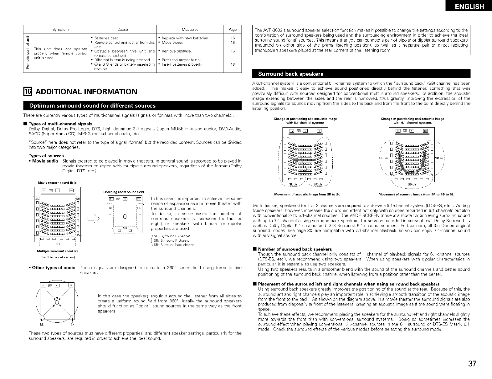
Symptom Cause Measu es Page
• Batteries dead • Replace with new batter es 6
• Remote control unit too far from this • Move closer 16
o
_d This url[t does not operate • Obstacle between ths unit and • Remove obstacle 16
o prope@ when remote co/t_ol remote cofstrol unit
® unit s used • Dlferent button s being pressed • Press the proper buttofl
• @ and @ ends of battery i/so ted in • Insert barCeries ploperly 16
everse
(monopolar) speakers placed at the rear corners of the listening room
_I_ I,_ _ _
[] ADDITIONAL INFORMATION
There are currently various types of mulLi<hannel signals (signals or formats with more than two channels)
•Types of multi-channel signals
Doby Digital, DoBy Pro Logc, DTS, high definition 3-1 signals (Japan MUSE Hi-Vision audio), DVD-Audio,
SACD (Super Audio CD), MPEG multi-channel audio, etc
"Source" here does nol refer to the type of signal (format) but the recorded content Sources can be divided
into two major categories
Types of sources
•Movie audio Signals created to be played in movie theaters In general sound s recorded to be played in
mowe theaters equipped with multiple surround speakers, regardless of the format (Doby
Digital, DTS, etc)
Movie theater sound field
D [] [] [] Listeningrooms_undfield
BI_====_IB , -, ,- ,
i SL_ ISR
J_'a_ uusuusuu_'_ j I J I J
I. )S SB "_1, )
B,_ussussus_,B _ Es Es ,
Multiple surround q_ilker s
(Fo G / clanre syster i!
In this case it is important to achieve the same
sense of expansion as in a movie theater with
the surround channels
To do so, n some cases tile number of
surround speakers is increased {to four or
eght) or speakers with bipolar or dipolar
properties are used
\ SB Surro net bacR channel
•Other types of audio These signals are designed to recreate a 360 ° sound field using three to five
speakers¸
{ Ciok
J> k
9L SR
In this case the speakers should surround the listener from all sides to
create a uniform sound field from 360 ° Ideally the surround speakers
should funct on as "point" sound sources in the same way as the front
speakers
These two types of sources thus have d fferent properties, and different speaker settings, particularly for the
surround speakers, are required in order to achieve the ideal sound
A 61 <hannel system is a conventional 51 -chanr_el system to which the "surround back" (SB) channel has been
added This makes it easy to achieve sound positioned directly behind the listener, something that was
previously difficult with sources designed for conventional multi surround speakers In addition, the acoustic
image extending between the sides and the rear is narrowed, thus greatly improving the expression of the
surround signals for sounds moving from the sides to the back and from the front to the point directly behind the
listening position
Change of positioning and a_oustic image
with 51-channel systems
[]_[] []
_s _sJks _
Change of positioning and acoustic image
with 6 l_chan_el systems
[] _ _ d_'_
[_ i_
[] u_uu_u
FE3 E3 E3 E3 E3 E3
Movement of acoustic image from SR _SL Mowmen_ of aco_sti_ image from SR to SB to SL
With this set, speaker(s) for 1 or 2 channels are required to achieve a 61-channel system (DTS-ES, etc) Adding
these speakers, however, increases the surround effect not only with sources recorded in 61 channels but also
with conventional bto 51-channel sources The WIDE SCREEN mode is a mode for achieving surround sound
with up to 71 channels using surround back speakers, for sources recorded in conventional Dolby Surround as
wellas Doby Digtal 5 %channel and DTS Surround 51<hannel sources Furthermore, allthe Denon original
surround modes (see page 30) are compatible with 71-channel playback, so you can eqoy 7 l<hannel sound
with any signal source
•Number of surround back speakers
Though the surround back channel only conssts of 1 channel of playback signals for 61-channel sources
(DTS-ES, etc), we recommend using two speakers When using speakers with dipolar characteristics in
particular, t is essential to use two speakers
Usng two speakers results in a smoother blend with the sound of the surround channels and better sound
positioning of the surround back channel when listening from a position olher than the center
•Placement of the surround left and right channels when using surround hack speakers
Usng surround back speakers greatly mproves the positioning of the sound at the rear Because of t_l_Srt_le
surround left and right channels play an important role in achieving a smooth transition of the acoustic image
from the front to the back As shown on the diagram above, in a movie theater the surround signaB are also
produced from diagonal]y in front of the listeners, creathg an acoustic image as if the sound were floating =n
space
To achieve these effects, we recommend phcing the speakers for the surround left and right channels slightly
more towards the front than with conventional surround systems Doing so sometimes increases the
surround effect when playing conventional _ l-channel sources in the 61 surround or DTS-ES Matrix 61
mode Check the surround effects of the various modes before selecting the surround mode
37
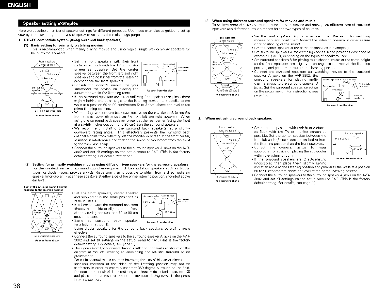
Here we describe a number of speaker settings for different purposes Use these examples as guides to set up
your system according to the type of speakers used and the main usage purpose
1. DTS-ES compatible system (using surround back speakers)
(1) Basic setting for primarily watching movies
This is recommended when mainly phyi_lg movies and using regular single way or 2-way speakers for
the surround speakers
Fro_lt speakers
S_rr_u_ld t_ack s eakers
As seen f_om ebove
• Set the front speakers with their front
surfaces as flush with the TV or monitor
screen as possible Set the center
speaker between the front left and right
speakers and no further from the listening
position than the front speakers
• Consul[ the owner's manual for your
subwoofer for advice on placing the Asseenfromtheside
subwoofer within the listening room
• If the surround speakers are direct-radiating (monopob) the_l place them
slightly behind and at an angle to the listening position and parallel to the
walls at a position 60 to 90 centimeters (2 to 3 feet} above ear level at the
prime listening position
• When usng two surround back speakers, place them at the back facing the
front at a narrower distance than the front left and right speakers When
using one surround back speakeE, place it at the rear center facing the front
at a slightly higher position (g to 20 cm) than the surround speakers
• We recommend instaJling the surround back speaker(s) at a slightly
downward facing angle This effectively prevents the surround back
channel signals from reflecting off the monitor or screen at the front center,
resulting in interference and making the sense of movement from the front
to the back less sharp
• Connect the surround speakers to the surround speaker A jacks on the AVR-
3802 and set all settings on the setup menu to "A" (This is the factory
default setting For details, see page 9)
(2} Setting for primarily watching movies using diffusion type speakers for the surround speakers
For the greatest sense of surround sound envelopme_lt, diffuse radiation speakers such as bipolar
types, or dipolar typesr provide a wider dispersion than is possible to obtain from a direct radiating
speaker (monopolar) Place these speakers at either side of the prime listening position, mounted above
ear level
Path of the surround sound from the
speeke_s to the _istening position
S_Jlrour_d I_ck _pea_ers
As seen from abOVe
• Set the front speakers, ce_lter speaker
and subwoofer in the same positions as
in example (1)
• It is best to place the surround speakers
d rectly at the side or slightly to the front
of the viewing position, and 60 to 90 cm
above the ears
• Same as surround back speaker Asseenfromtheside
instaJlation method (1)
Using dipolar speakers for the surround back speakers as well is more
effective
• Connect the surround speakers to the surround speaker A iacks on the AVR-
3802 and set all settings on the setup menu to "A" (This is the factory
default setting For details, see page 9)
• The signals from the surround channels reflect off the walls as shown on the
dagram at the left, creating an enveloping and realistic surround sound
presentation
For multi-channel music sources howeverr the use of bipolar or dipolar
speakers mounted at the sides of the listening position may not be
satifactory in order to create a coherent 360 degree surround sound feld
Connect another pair of direct radiating speakers as described n example (3)
and place them at the rear corners of the room facing towards the pnme
listening position
38
(3} When using different surround speakers for movies and music
To achieve more effective surround sou_ld for both movies and music, use different sets of surround
speakers a_ld different surrou_ld modes for the two types of sources
/ FrOl_t speakers _
Ce_l_e_ spe_ker
120 _
S_JlTour_dspeaker s B
As seen from above
• Set the front speakers slightly wideE apart than the setup for watching
mowes only and point them toward the listening position in order assure
clear positioning of the sound
• Set the center speaker in the same positions as in example (1)
• Set surround speakers A for watching movies in the positions descr bed in
example (1) or (2}r depending on the types of speakers used
• Set surround speakers B for playing multi-channel music at the same height
as the front speakers and slightly at an angle to the rear of the listening
posit on, and point them toward the listening posit on
• Connect tile surround speakers for watching movies to the surround
speaker A jacks on the AVR-3802r the
surround speakers for playing muki-
channel music to the surround speaker B
jacks Set the surround speaker selection
on the setup menu {For instruct ons, see
page 10)
As seen from the side
2. When not using surround back speakers
Surround spe_kelS
As seen from above
• Set the front speakers with their front surfaces
as flush with the TV or monitor screen as S_rr_uid speaker
possbb Set the center speaker between the
front left and right speakers and no further from
the listening position than the front speakers
• Consult the owner's manual for your
subwoofer for advice on placing the subwoofer
within the listening room
• If the surround speakers are drect-radating Asseenfr°m the side
(monopolar) then place them slightly behind
and at an angle to the listening position and parallel to the walls at a position
6g to g0 centimeters above ear level at the prime listening position
• Connect the surround speakers to the surround speaker A jacks on the AVR-
3802 and set all settings on the setup menu to "A" (This is the factory
default setting For details, see page g)
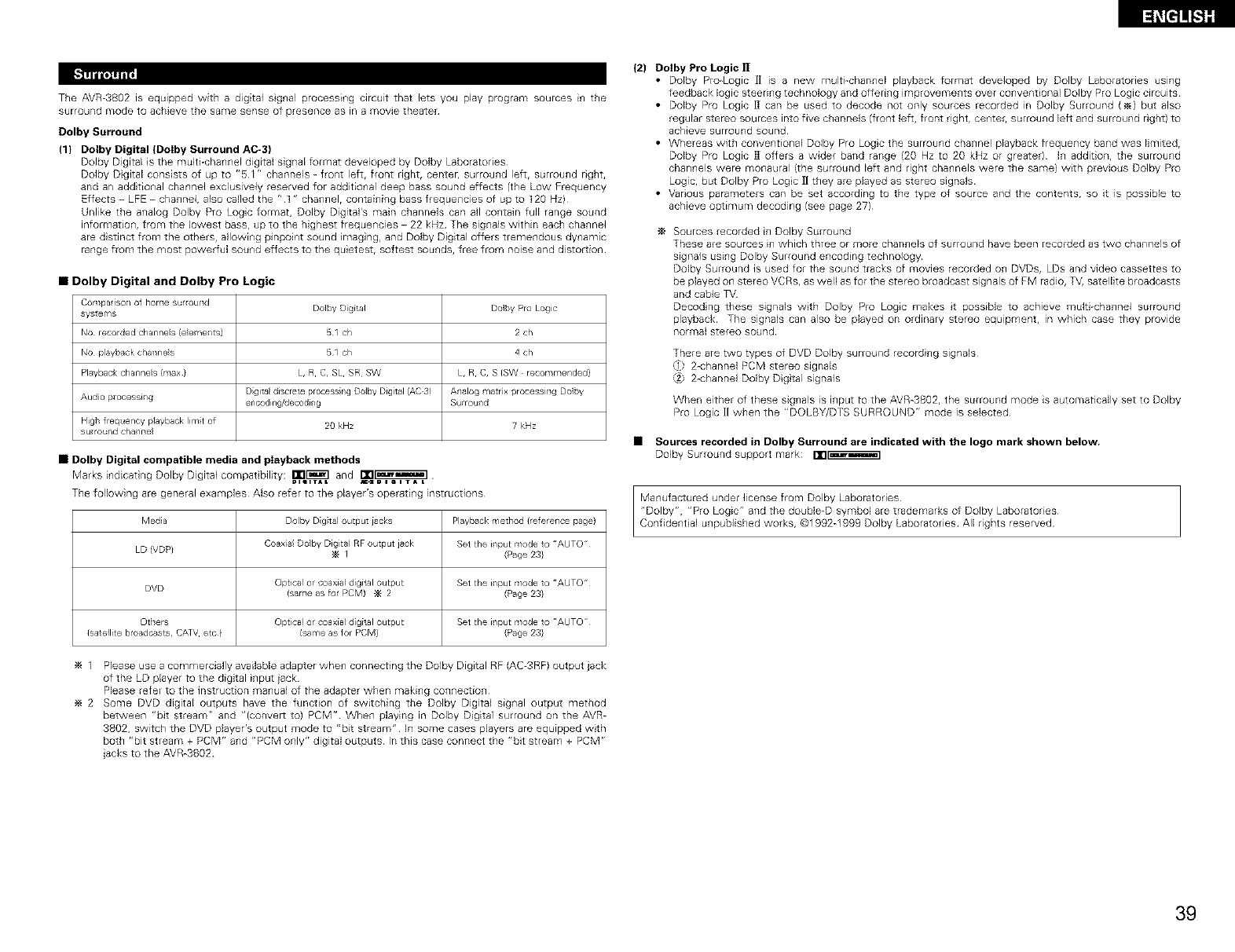
TheAVR-3802isequippedwithadigitalsgnalprocessingc4rcultthatletsyouplayprogramsourcesinthe
surroundmodetoachievethesamesenseofpresenceasinamovietheater
Dolby Surround
(1} Dolby Digital (DoIby Surround AC-3)
Dolby Digital s the multi-channel digital signal format developed by Dolby Laboratories
Dolby D gital consists of up to "51" channels _ front left, front right, center, surround left, surround right,
and an add tional channel exclusively reserved for additional deep bass sound effects (the Low Frequency
Effects - LFE - channel, also called the "t " channel, containing bass frequencies of up to 120 Hz)
Unlike the analog Dolby Pro Logc format, Dolby Digi[al's main channels can all contain full range sound
information, from the lowest bass, up to the highest frequencies - 22 kHz The signals within each channel
are d stinct from the others, allowing p_npoint sound hag ng, and Dolby Digital offers tremendous dynamic
range from the most powerful sound effects to the quietest, softest sounds, free from noise and distortion
Dolby Digital and Dolby Pro Logic
Conlpa [so/ of home st,round Doloy Digital Doloy Pro Logic
systems
NO recorded charlr/es (e e¥_e/ts) 51 ch 2 ch
NO playbackchanr/e s 51 ch 4 ch
Playbackcharlr/e s (max} L, R C, SL SR SW L, R C, S (SW recommended}
Dgital discrete processng DolbyDigital rAG3) Analog matrx processing Dolby
Audo processi/g encoding/decoding Surrou/d
High frequency playback lirnt of 20 kHz 7 kHz
su round cha/he
•Dolby Digital compatible media and pIayback methods
Marks indicat ng Dolby Digital cornpat bilky: Ilrl[_] and iTl_]_]
=I,ITAL m,ZOImlTAL
The following are general examples Also refer to the player's operating instructions
Media Dolby Dgtal output iacks Playback method (reference page)
Coaxa Doby Digita RF output jack Set the i/put mode to "AUTO
LD (VDP) _ I (Page 23}
DVD Optical or coaxial d g[tal output Set the i/put mode to "AUTO
(same as for PCM) _ 2 (Page 23}
Others Optical or coaxial d g[tal output Set the i/put mode to "AUTO
(satellite broadcasts, CATV etc} (same as for PCM} (Page 23}
1 Please use a commercially available adapter when connecting the Dolby Digital RF (AC-3RF) output jack
of the LD player to the digital input iack
Please refeE to the instruction manual of the adapter when making connection
2 Some DVD digital outputs have the function of switching the Dolby Digital signal output method
between "bit stream" and "(conver_ to) PCM" When playing in Dolby Digital surround on the AVR-
3802, switch the DVD player's output mode to "bit stream" In some cases players are equipped with
both "bit stream + RCM" and "PCM only" digital outputs In this case connect the "bit stream + PCM r,
Jacks to the AVR-3802
(2) Dolby Pro Logic ]1
• Dolby Pro-Logic ]] is a new multFchannel playback format developed by Dolby Laboratories using
feedback logic steering technology and offering improvements over conventional Dolby Pro Logic circuits
• Dolby Pro Logic l] can be used to decode not only sources recorded in Dolby Surround (_) but also
regular stereo sources into five channels (front left, front rightr centel, surround left and surround right) to
achieve surround sound
• Whereas with conventional Dolby Pro Logc the surround channel playback frequency band was limited,
Dolby Pro Logic R offers a wider band range (2g Hz to 20 kHz or greater) In addition, the surround
channels were monaural (the surround left and right channels were the same) with previous Dolby Pro
Logic, but Dolby Pro Logc ]1they are played as stereo signals
• Various parameters can be set according to the type of source and the contents, so it is possible to
achieve optimum decoding (see page 27)
Sources recorded in Dolby Surround
These are sources m which three or more channels of surround have been recorded as two channels of
signals using Dolby Surround encoding technology
Dolby Surround is used for the sound tracks of movies recorded on DVDs, LDs and video cassettes to
be played on stereo VCRs, as well as for the stereo broadcast signals of FM radio, TV, satellite broadcasts
and cable ]_/
Decodng these signals with Dolby Pro Logic makes t possible to achieve muki-channel surround
playback The signals can also be played on ordinary stereo equipment, in which case they provide
normal stereo sound
There are two types of DVD Dolby surround recording signals
,1 2-channe PCM stereo signals
,2; 2-channe Dolby Digtal signals
When either of these signals is input to the AVR-3802, the surround mode is automatically set to Dolby
Pro Logic ][ when the "DOLBY/DTS SURROUND" mode is selected
•Sources recorded in Dolby Surround are indicated with the logo mark shown below,
Dolby Surround support mark: nn_]
Manufactured under license from Dolby Laboratories
"Dolby", "Pro Logic" and the double-D symbol are trademarks of Dolby Laboratories
Confident al unpublished works, @1992_1999 Dolby Laboratories All rights reserved
39
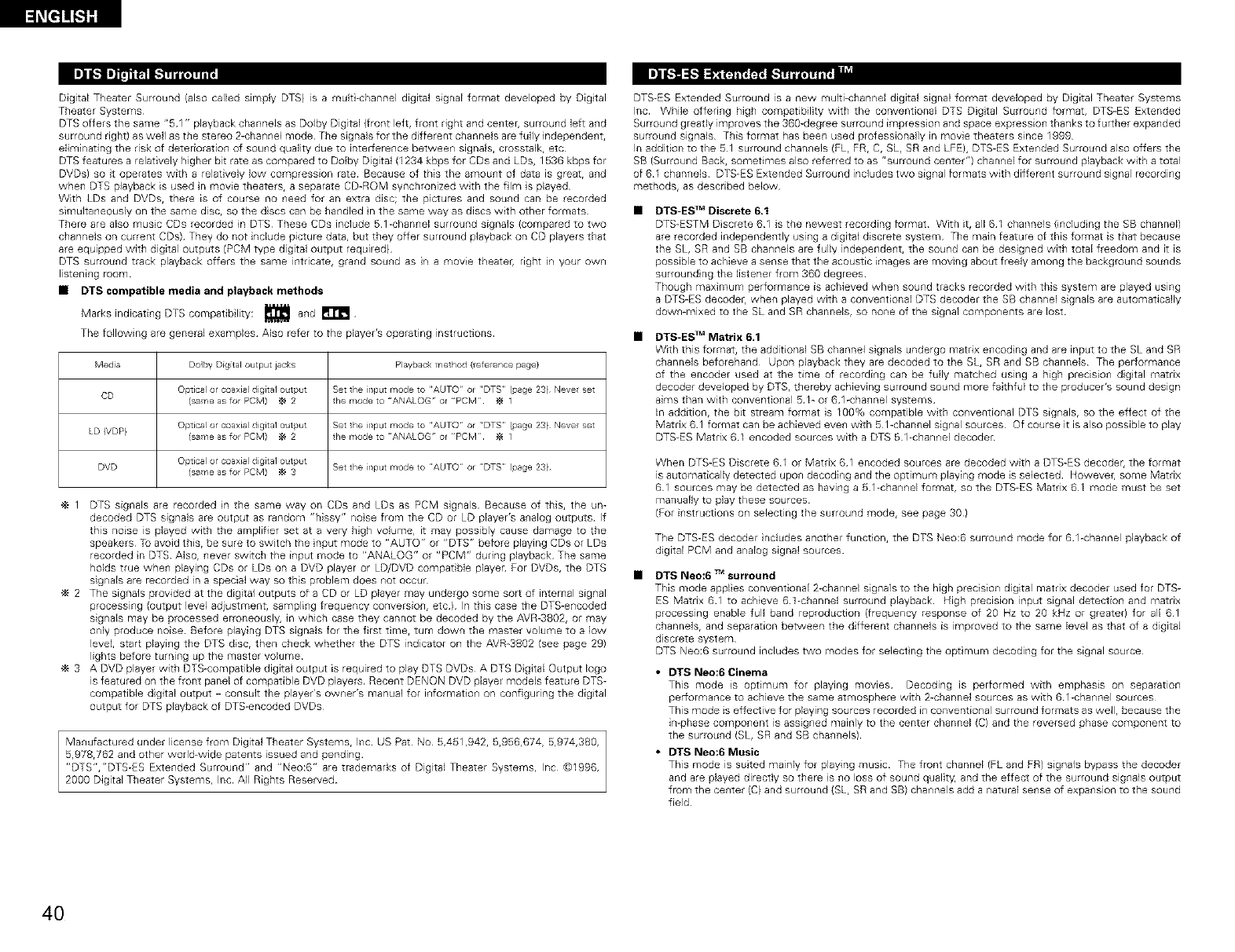
l_[l]!!!;Sll
IJl I[-1I]'_'J_ [-._
Digital TheateE Surround (also called simply DTS) is a mult-channel digiLal signal format developed by Digtal
TheateE Systems
DTS offers the same "51 " playback channels as Dolby Digital (front left, front right and cente{, surround left and
surround right) as well as the stereo 2-channel mode The signals for the d fferent channels are fully independent,
eliminating the risk of deterioration of sound quality due to interFerence between signals, crosstalk, etc
DTS features a relatively higher bit rate as compared to Dolby Digital (1234 kbps for CDs and LDs, 1536 kbps for
DVDs) so it operates with a relatively low compression rate Because of this the amount of data is great, and
when DTB playback is used n movie theaters, a separate CD-ROM synchronized with the fire s played
With LDs and DVDs, there is of course no need for an extra disc; the pictures and sound can be recorded
simultaneously on the same disc, so the dscs can be handled n the same way as discs with other formats •
TheEe are also musc CDs recorded in DTS These CDs include 51-channel surround signals (compared to two
channels on current CDs) They do not include picture data, but they offer surround playback on CD players that
are equipped with digital outputs (PCM type digital output requi_ed)
DTS surround track playback offers the same intricate, grand sound as in a movie theateE, right in your own
listening room
•DTS compatible media and playback methods
Marks indicati_lg DTS compatibility: _ a_ld
The following are general examples Also refer to the player's operating instructions •
Media Dolby Digital output jacks Playback method (refe ence page(
CD Optical or coaxial digital output Set the input mode to "AUTO' or 'DTS (page 23} Neve set
(sa ¥_eas for PCM) _ 2 the mode to "ANALOG' or "PCM _ 1
Optical or coaxial digital output Set the input mode to "AUTO' or 'DTS (page 23} Neve set
LD (VDP} (sa ¥_eas for PCM) _ 2 the mode to "ANALOG' or "PCM _ 1
DVD Optical or coaxial digit al output
(sa¥_e as for PCM) _ 3 Set the input mode to AUTO' or DTS (page 23}
1 DTS signals are recorded n the same way on CDs and LDs as PCM sg_lalS Because of this, the un-
decoded DTS signals are output as random "hissy" nose from the CD or LD player's analog outputs If
this noise is played with the amplifier set at a very high volume, it may possibly cause damage to the
speakers T_ avoid this, be sure to switch the nput mode to "AUTO" or "DTS" before playing CDs or LDs
recorded n DTS Also, never switch the input mode to "ANALOG" or "PCM" during playback The same
holds true when playing CDs or LDs on a DVD player or LD/DVD compat ble player For DVDs, the DTS
signals are recorded in a special way so this problem does not occur
2 The signals provided at the digital outputs of a CD or LD player may undergo some sor_ of internal signal
processing (output level adjustment, sampling frequency conversion, etcl In this case the DTS-encoded
signals may be processed erroneousl% in which case they cannot be decoded by the AVR-3802, or may
only produce noise Before playing DTS signals for the first time, turn down the master volume to a low
level, start playing the DTS disc, then check whether the DTS indicator on the AVR-3802 (see page 29)
lights before turning up the master volume
3 A DVD player with DTB-compatible digital output is required to play DTS DVDs A DTS D gital Output logo
is featured on the front panel of compatible DVD players Recent DENON DVD playeE models feature DTS-
compatible digital output - consult the player's owner's manual for informat on on configuring the digtal
output for DTS playback of DTS-encoded DVDs
Ma_lufactured under license from Digital Theater Systems, Inc US Pat No 5,451,942, 5,956,674, 5,974,380,
Br97B,762 _ are trademarks of Digital Theater Systems, Inc @1996,
and other world-wide patents isoued and pending
"DTS","DTS-ES Extended Surround" and "Neo:6"
2000 Digital Theater Systems, Ir_c All Rights Reserved
DTS-ES Exte_lded Surround is a new multi-channel digital signal format developed by Digital Theater Systems
Inc While offering high compatibility with the conventional DTB Digtal Surround format, DTS-ES Extended
Surround greatly improves the 360-degree surround impress on and space expression thanks to further expanded
surround signals This format has been used professionally in movie theaters since 1999
In addition to the 51 surround channels (EL, FR, C, SL, BR and LEE}, DTS-ES Extended Surround also offers the
SB (Surround Back, sometimes also referred to as "surround center") channel for surround playback with a total
of 61 channels DTS-ES Extended Surround includes two signal formats with different surround signal recording
methods, as described below
DTS-E$ TM Discrete 6.1
DTS-ESTM Discrete 61 is the newest recording format With it, all 61 channels {including the SB channel)
are recorded independently using a digital discrete system The main feature of this format is that because
the SL, SR and BB channels are fully independent, the sound can be designed with total freedom and it is
possible to achieve a sense that the acoustic images are moving about freely among the background sounds
surround ng the listener from 360 degrees
Though maximum performance is achieved when sound tracks recorded with this system are played using
a DTS-ES decodeE, when played with a conventional DTS decodeE the SB channel signals are automatically
down-mixed to the BL and SR channels, so none of the signal components are lost
DTS-ES TM Matrix 6,1
With this format, the additional SB channel signals undergo matrix encod ng and are input to the SL and SR
channels beforehand Upon playback they are decoded to the 9L, SR and SB channels The performance
of the encoder used at the time of recording can be fully matched using a high precision digtal matNx
decoder developed by DTB, thereby achieving surround sound more faithful to the producer's sound design
aims than with conventional 51- or 61-channel systems
In addition, the bit stream format is 100% compatible with conventional DTS signals, so the effect of the
Matrix 61 format can be achieved even with 5 l-channel signal sources Of course it is also possible to play
DTS-ES Matrix 61 encoded sources with a DTS 51-channel decoder
When DTS-ES Discrete 61 or Matrix 61 encoded sources are decoded with a DTS-ES decoder, the format
is automatically detected upon1decoding and the optimum playing mode is selected However, some Matrix
61 sources may be detected as having a 51-channel format, so the DTS-ES Matrix 61 mode must be set
manuaNy to play these sources
(For i_lStructions o_1selecting the surround mode, see page 30)
The DTS-ES decoder ncludes another function, the DTB Neo:6 surrou_ld mode for 61-cha_1nel playback of
digital PCM and analog signal sources
DTS Neo:6 TMsurround
This mode applies conventional 2-channel signals to the high precision digital matrix decoder used for DTS-
ES Matrix 61 to achieve 6 t-channel surround playback High precision input signal detection and matrix
processing enable full band reproduction (frequency response of 20 Hz to 20 kHz or greater) for all 61
channels, and separation between the different channels is improved to the same level as that of a digital
d screte system
DTS Neo:6 surround includes two modes for select ng the opt mum decoding for the signal source
• DTS Neo:6Cinema
This mode is optimum for playing movies Decoding is performed with emphasis on separation
performance to achieve the same atmosphere with 2-channel sources as with 61-channel sources
This mode is effective for playing sources recorded in conventional surround formats as well, because the
imphase component is assigned mainly to the center channel (C) and the reversed phase component to
the surround (SL, SR and SB channels)
• DTS Neo:6 Music
This mode is suited mainly for playing musc The front channel (FL a_ld ER) signals bypass the decoder
and are played directly so there s _1oloss of sound quality, and the effect of the surround signals output
from the ce_lter (C) and surround {SL, SR and SB) cha_lnels add a natural se_lse of expa_lsion to the sound
field
4O
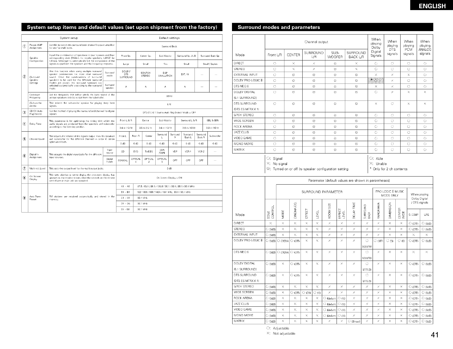
System setup
m_,;,,,x_,
su_oui@
L_
C _X_A, OPTiCaL OPTi(_L OPTi(_L 0 _ 0 _ 0
_1 ,, _ 9O ! MH__
Mode
DIRECT
STERE()
EXTERNAL INPL]
DOLBY PRO LOGIC ]]
DTS NEO6
DOLBY DIGITAL
(6 I SURROUNDI
DTS SURROUND
_DTS ES MTRX 6 /}
!i/7 C H S_EREO
WIDE SCREEN
ROCK ASENA
JAZZ CLUB
VIDE(} GAME
MONO MOVIE
MATRIX
Mode
DIRECT
STERE()
EXTERNAL INPL]
DOLBY PRO LOGIC 11
When
Channel output playing When When When
Dolby playing playing playing
DTS PCM ANALOG
SURROUND SUB SURROUND Digital signals signals signals
Frol/t L/R CENTER L/R WOOFER BACK L/R Signals
_) X
_) >
:NO sigllal
Tumed oil or of r_y speaker configuratio_/ setting
Parameter (defaul values are shown in pare_/theses)
o8
>
( (OdB
( (OdB
( (OdB
SURROUND PARAMETER
8
o
s s
X X x x £ £
X X x x £ £
X X x x £ £
( :,E_ (OFF) X X / /
PRO LOGIC H MUSIC
MODE ONLY When p_ay_ng
Doll W Digital
<r _ /D_S s_gnals
o • _ _ COMP LFE
( (OFF ( (OdB
( (OFF ( (OdB
_ _ >_ >_
DOLBY DIGITAL (i (OdBi >_ (i iOFF) X X ///(} /(i (OFFi (i (OdBi
DTS SURROUND (i (OdBi >_ (i iOFF) X X ///(} /(i (OFFi (i (OdBi
(DTS ES MTRX 6 /} _ 01_
WIDE SCREEN (i(OdBi >_ (iiOFF) _) iON} } i/0 / / / / / (i(OFFi (i(OdBi
ROCKASENA (i(OdBi >_ >_ X X _)i_diu_q (}(1_ / / / (i(OFF i (i(OdBi
JAZZCLUB (i(OdBi >_ >_ X X _)i_diu_q (}(1_ / / / (i(OFF i (i(OdBi
VlDEOGAME (i(OdBi >_ >_ X X _)i_diu_q (}(1_ / / / (i(OFF i (i(OdBi
MONO MOVIE (i (OdBi >_ >_ X X _) i_diu_q (} (1_ / / / (i (OFFi (i (OdBi
k_: Adjustable
x Not adiustable 41
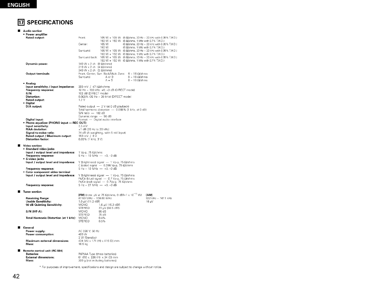
[] SPECIFICATIONS
• Audio section
•Power amplifier
Rated output:
Dynamic power:
Output terminals:
•Analog
input sensitivity /input impedance:
Frequency response:
S/N:
Distortion:
Rated Output:
• Digital
D/A output:
Digital input:
FroTlt: 105W+ 105W (8 £1/ohms 20 Hz 2L_kHz with 005% T H D }
150W+150V {6_/ohms lkl_zwithLL7%THD)
Center: 105 W {8 _/ohms 20 Hz - 2L_kHz with 0¸05% T IqD }
150 W {6 _/ohms 1 kl_z with LL7% THD)
Surround¸ 105W+105W {8_l/ohms 20Hz-2L_kHzwith005%THD}
150W+lSOW {6_l/ohms lkl_zwithLL7%THD)
Surround back: 105 W + 105 W {8 _/ohms 20 Hz N 2L_kHz with 0¸05% THD}
150 W + 150 V {6 _dohms 1 klqz with (}¸7% THD(
140Wx2 ch (8 _/ollms}
21OWx2 ch (4 _/ollms}
240 W x 2 ch (2 _/ollms}
Front¸ CeTlte_ Surf Back/Multi Zone: 6 N 16 _/ohms
Surround¸ A or B 6 N 16 _/ohms
A+ B 8 - 16 _/ohms
200 mV /47 k_J/kollr'ls
10bz 100kHz:+O _dB(DIRECTmode}
102 dB (DIRECT mode}
0 005% (20 Hz - 20 kHz} (D_RECT mode(
12V
Rated output 2 V (at 0 dB playback}
Total/armonic distortion 0008% (1 kHz at 0 dB}
S/N ratio 102 dB
Dynam c ra/ge 96 dB
Format Dig tal audio i/terrace
•Phono equalizer (PHONO input -- REC OUT)
Input sensitivity: 2 5 r,lV
RIAA deviation: +1 dB (20 Hz to 20 kHz)
Signal-to-nolse ratio: 74 dB (A weigllting, w_tll 5 mV input}
Rated output /Maximum output: 150 mV /8 V
Distortion factor: 0 03% (1 kHz 3 V}
•Video section
•Standard video jacks
Input /output level and impedance:
Frequency response!
•S-video jacks
Input /output level and impedance:
Frequency response/
•Color component video termlnal
Input /output level and impedance:
Frequency response:
I Vp_p, 75 £_/o}/ms
5Hz 10MHz TO,_dB
Y (br;g/tness} s gl/al 1 Vp p, 75 £_/o}1ms
C (color} signal 0286 Vp p, 75 _/oh ¥_s
5Hz_IOMHz T0,_ dB
Y (br;g/tness} s;gl/al I Vp p, 75 £_/o}/m s
PB/CB {blue} sigl/al 07 Vp p, 75 £_/o}/ms
PR/CR (red} signal OTVp p, 75 _hms
5Hz_27MHz +O,_ dB
•Tuner section
IFMI (l/ore: IJV at 75 _/o}/ms, 0 dBf I x 10 W) [AM]
Reseiving _ange: 8?50 MHz 10800 MHz 522 _<Hz 161 I kHz
Usable Sensitivity: I 0 pV (11 2 dBf) 18 pV
50 dB Quieting Sensitivity: MQNQ 16 pV (153 dBf)
STEREO 23 _V (385 dBf)
SIN (IHF_A): MQNQ 80 dB
STEREO 75 dB
Total Harmonic Distortion {at 1kHz): MON© 04%
STEREO 05%
•General
Power supply: AC 230 V 50 Hz
Power consumption: 400 W
2 W (Stal/dby)
Maximum external dimensions: 434 (W) x 171 (H) x 416 (D} mr,/
Mass: 165 g
•Remote control unit (RC-884)
Batteries:
External dimensions:
Mass:
R6P/AA Type (three batter es)
61 {W) x 230 (H} x 34 {D) mm
200 g (not il/clud[ng batteries}
For purposes of improvement, specif[cat[or/s and design are subject to change without notce
42
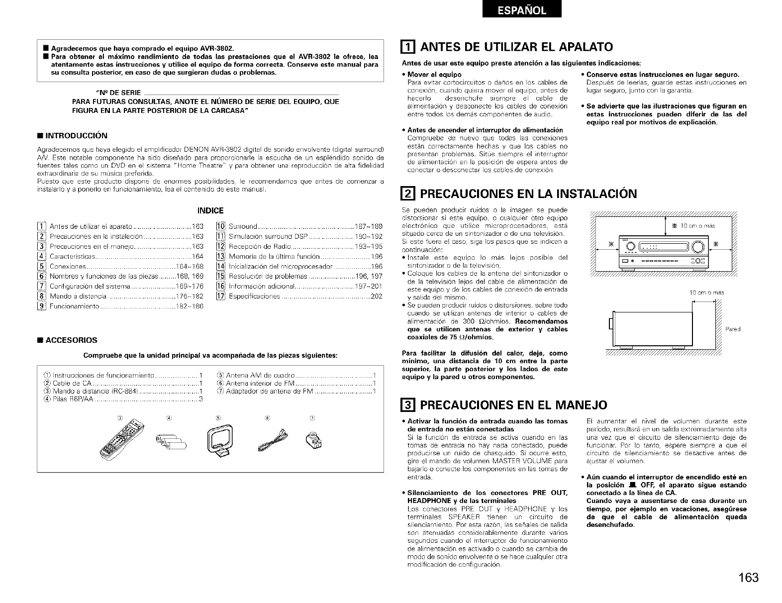
•Agradecemos que haya comprado el equipo AVR-3802.
•Para obtener el maximo rendimiento de todas las prestaciones que el AVR-3802 le ofrece, lea
atentamente estas instrucciones y utilice el equipo de forma correcta. Conserve este manual para
su consulta posterior, en caso de que surgieran dudas o problemas.
"N _DE SERIE
PARA FUTURAS CONSULTAS, ANOTE EL Nt_IMERO DE SERIE DEL EQUIPO, QUE
FIGURA EN LA PARTE POSTERIOR DE LA CARCASA"
•INTRODUCCI()N
Agradecemos que haya eleg do el amplificador DENON AVR-3802 d gital de sonido envolvente (digital surround)
A_! Este notable componente ha sido diserqado para proporcionade la escucha de un esplendido sonido de
fuentes taEes como un DVD en el sistema "Home Theatre" y para obtener una reproducciOn de alta fideEdad
extraordinada de su m_islca prefeE da
Puesto que este producto dispone de enormes posibiEidades, le recomendamos que antes de comenzar a
instalado y a ponedo en funcionamiento, lea el contenido de este manual
INDICE
J]J Antes de u61izar el aparato .............................. 163
12_] Precauciones en la instalaci0n ......................... 163
Ja] Precauciones en el manejo .............................. 163
14] Caractedsticas .................................................. 164
Ls]Conexiones .............................................. 164-168
J6_] Nombres y funciones de las piezas ......... 168, 169
h_'J Conflguracion del sistema ....................... 169~176
18] Mando a distancia ................................... 176-182
[_] Funcionamiento ....................................... 182-186
I10] Surround .................................................. 187-189
Ilj] SimulaciOn surround DSP ........................ 190-192
112] Recepcion de Radio ................................. 193-195
113] Memoda de la Oltima funcion .......................... 196
l_J Inicializaci0n del mlcroprocesador ................... 196
II_J ResoluciOn de problemas ........................ 196, 197
116] Informaci0n adicional ............................... 197-201
[i7] Especificaciones .............................................. 202
•ACCESORIOS
Compruebe que la unidad principal va acompa_,adade las piezas siguientes:
,_1)InstruccJones de funcionamiento ....................... 1
Cable de CA ....................................................... 1
Mando a distancia (RC_884) ............................... 1
Pilas R6P/AA ...................................................... 3
_5 Antena AM de cuadro ........................................ 1
Antena interior de FM ........................................ 1
Adaptador de antena de FM .............................. 1
[] ANTES DE UTILIZAR EL APALATO
Antes de usar este equipo preste atencion a las siguientes indicaciolles:
• Mover el equipo
Para evitar cortocircuitos o danos en los cables de
conexion, cuando quiera mover el equipo, antes de
hacedo desenchufe siempre el cable de
alimentacion y desconecte los cables de conexion
entre todos los demas componentes de audio
•Antes de encender et interruptor de alimentacion
Compfu@be de nuevQ que todas las conexiones
est_n correctalnel]te hechas y que los cables llo
presentan problemas Sit0e siempre el interruptor
de alirnentaci@l en la posicion de espera antes de
COllectar o descQnectar JQS cabJes de conexion
•Conserve estas instrucciones ell _ugar seguro.
Despues de leedas, guarde estas instrucciones en
lugar seguro, junto con la garanda
•Se advierte que las ilustraciones que figuran en
estas instrucciones pueden diferir de las del
equipo real pot motivos de explicacion.
[] PRECAUCIONES EN LA INSTALACION
Se pueden producir ruidos o la magen se puede
distorsionar si este equlpo, o cualquier otro equipo
electronico que utlice m_croprocesadores, esta
sltuado cerca de un sintonizador o de una television
Si este fueEa el caso, siga los pasos que se ndican a
continuacion:
• Instale este equipo Io mas lejos posible del
sintonizador o de la television
• Coloque los cables de la antena del sintonizador o
de la television lejos del cable de alimentacion de
este equipo y de los cables de conexiOn de entrada
y salida del mismo
• Se pueden producir ruidos o d storsiones, sobre todo
cuando se utilizan antenas de interior o cables de
alimentaciOn de 300 £dohmios Recomendamos
que se utiticen antenas de exterior y cables
coaxiales de 75 £)/ohmios.
10 cm o mas
Pa_ed
Para facilitar Ia difusidn del calor, deje, como
millimo, ulla distancia de 10 cm entre la parte
superior, la parte posterior y los Iados de este
equipo y la pared uotros componentes.
[] PRECAUCIONES EN EL MANEJO
•Activar la funcion de entrada cuando Ias tomas
de entrada no estan conectadas
Si la funci0n de entrada se acOva cuando en las
tomas de entrada no hay nada conectado, puede
producirse un ruido de chasquido S ocurre esto,
gire el mando de volumen MASTER VOLUME para
bajarlo o conecte los componentes en las tomas de
entrada
•Silenciamiento de los conectores PRE OUT,
HEADPHONE y de las terminales
Los conectores PRE OUT y HEADPHONE y los
terminales SPEAKER tienen un cErcuito de
silenciamiento Por esta razOn, las senales de salida
son atenuadas consderablemente durante vados
segundos cuando el interruptor de funcionamlento
de aEmentaci0n es activado o cuando se cambia de
modo de sonido envolvente o se Race cualquier otra
modificacion de configuraciOn
El aumentar el nivel de volumen durante este
pedodo, resultara en un salida extremadamente alta
una vez que el circuito de silenciamiento de}e de
funcionar Pot Io tanto, espere siempre a que el
circuito de silenciamiento se desac6ve antes de
alustar el volumen
•Aun cuando el illterruptor de encendido este en
la posicidn II OFF, el aparato sigue estando
conectado a la linea de CA,
Cuando vaya a ausentarse de casa durante un
tiempo, por ejemplo en vacaciones, asegdrese
de que el cable de alimentacidn queda
desenchufado.
163
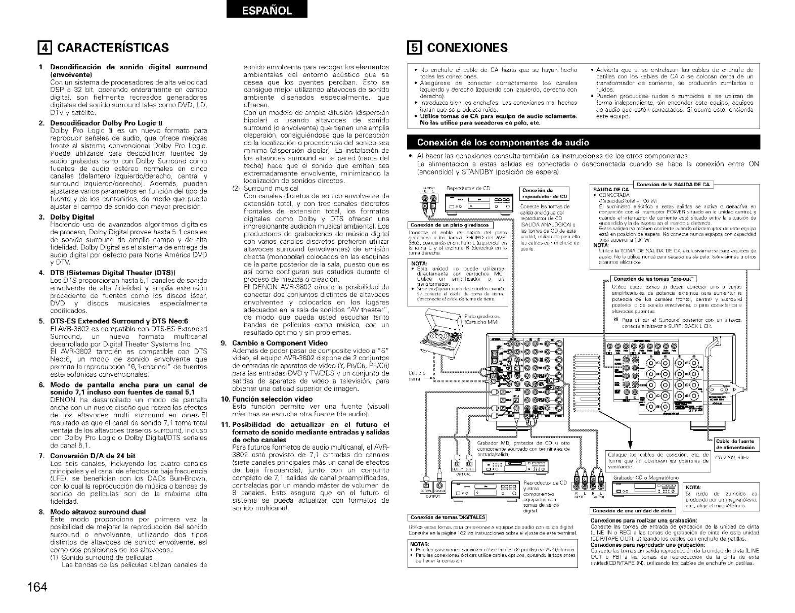
[] CARACTERiSTICAS
1. Decodificacion de sonido digital surround
(envoIvente}
Con un sistema de procesadores de alta velocidad
DSP a 32 bit, operando enteramente en campo
digital, son fielmente recreados generadores
digitales del sonido surround tales como DVD, LD,
DTV y satelite
2. Descodgicador Dolby Pro Logic I1
Dolby Pro Logic tl es un nuevo formato para
reproducir senales de audio, que ofrece mejoras
frente al sistema convencional Dolby Pro Logic
Puede utilizarse para descodificar fuentes de
audio grabadas tanto con Dolby Surround como
fuentes de audio est@eo normales en cinco
canales (delantero izquierdo/derecbo, central y
surround izquierdo/deEecho) Ademas, pueden
ajustarse vados parametros en funcion del tipo de
fuente y de los contenidos, de modo que puede
ajustar el campo de sonido con mayor precision
3. Dolby Digital
Haciendo uso de avanzados algodtmos digilales
de proceso, Dolby Dig tal provee hasta 51 canales
de sonido surround de amplio campo y de alta
fidelidad Dolby Digital es el sistema de entrega de
audio dig tal por defecto para None Amedca DVD
y DTV
4. DTS (Sistemas Digital Theater (DTS)}
Los DTS proporcionan hasta 5,1 canales de sonido
envolvente de alta fidelidad y amplia extension
procedente de fuentes como los discos laseh
DVD y discos musicales especialmente
codificados
5. DTS-ES Extended Surround y DTS Neo:6
El AVR_3802 es compatible con DTS-ES Extended
8urrouod, un nuevo formato muIticanal
desarrollado por Digital Theater Systems Inc
El AVR-3802 tambien es compatible con DTS
Neo:6, un modo de sonido envolvente que
permite la reproduccion "6,1-channel" de fuentes
estereQf6nicas convencionales
6. Modo de pantalla ancha para un canal de
sonido 7,1 incluso con fuentes de canal 5,1
DENON ha desarrollado un modo de pantalla
ancha con un nuevo diseno que recrea los efectos
de los altavoees muki surround en einesE]
resultado es que el canal de sonido 7,1 toma total
ventaja de los altavoces traseros surround, inciuso
con Dolby Pro Logic o Dolby Digital/DTS senales
de canal 5,1
7. Conversion D/A de 24 bit
pdncipales y el canal de efectos de baja frecuencia
(LEE), se benefician con los DACs BurPBrown,
con Io cual la reproduccion de masica o bandas de
sondo de peliculas son de la maxima alta
f delidad
8. Modo altavoz surround dual
Este modo proporclona por prlloera vez la
posib lidad de roejorar la reproducci6n del sonido
surrouild o er_volveilte r utilizando dos tipos
distintos de altavoces de sonido envolvente, asi
como dos poslcEolles de los altavoces :
11/ Sonido surround de peflculas
Las bandas de las peliculas utilizan canales de
sonido envolvente para recoger los elementos
ambientales del entomo acQstico que se
desea que los oyentes perciban Esto se
cons_gue mejor utilizando altavoces de sonido
ambiente disenados especialmente, que
ofrecen
Con un modelo de amplia difusi6n (d spersi6n
bipolar) o usando altavoces de sonido
surround (o envolvente) que tienen una amplia
dispersi6n, consiguiendose que la percepci6n
de la IocalizaciOn o procedencia del sonido sea
minima (dispers6n dipolar) La instalaci6n de
los altavoces surround en la pared (cerca del
techo) hace que el sonido que emiten sea
extremadamente envolvente, minimizando la
Iocalizaci6n de sonidos directos
(2) Surround musical
Con canales d cretos de sonido envolvente de
extension total, y con tres canales discretos
frontales de extension total, los formatos
dgitales como Dolby y DTS ofrecen
mpresionante audici6n musical ambiental Los
productores de grabaciones de mL_sica digital
con vanos canales discretos prefieren utilizar
altavoces surround (envolventes) de emision
directa (monopolar) colocados en las esqumas
de la par_e posterior de la sala, puesto quees
asi como configuran sus estudios durante el
proceso de mezcla o creaci6n
El DENQN AVB-3802 ofrece la posib lidad de
conectar dos conjuntos d stintos de altavoces
envolventes y colocados en los lugares
adecuados en la sala de sonidos "AV theater",
de modo que pueda usted escuchar tanto
bandas de peliculas como mOslca, con un
resultado optmo y sin problemas
9. Cambio aComponent Video
Ademas de podeE pasar de corr@osite video a "S r_
video, el equipo AVR-3802 dispone de 2 con juntos
de entradas de aparatos de video (Y, PB/C8, PR/CR)
para las entradas DVD y TV/DBS y un conjunto de
salidas de aparatos de video a television, para
obtener una calidad superior de imagen
10. Funcion seleccion video
Esta funciOn permite vet una fuente (visual)
mientras se escucba otra fuente (de audio)
11.Posibilidad de actualizar en el futuro el
formato de sonido mediante entradas y salidas
de ocho canales
Para futuros formatos de audio multicanal, el AVR_
3802 esta provisto de 7,1 entradas de canales
(siete canales pdncipales mas un canal de efectos
de baja frecuencia), junto con un conjunto
completo de 7,1 salidas de canal preamplificadas,
contraladas pot un mando master de volumen de
B canales Esto asegura queen el futuro el
slstema se pueda actualizar coil formatos de
sonido multicanal
[] CONEXIONES
• NO enchufe e] cable de CA /asta que se hayar/ [/ec/o
todas las cortex[ones
• Aseg0_ese de co_/ectar correctamer_te los ca_/ales
izquierdo y L)erec_/o I[zquierdo con [zquierdo derectlo col/
derecho)
• Introduzca bien los enc/ufes Las conex[ones real hechas
/ar_n que se produzca rude
•Utilice tomas de CA para equipo de audio solamenle.
No las utilice para secadores de pelo, etc.
• Adverta que si se entre]azan los cables de etlohufe de
pati}las cof_ los cables de CA o se colocan cesta de un
transfo_mador de cor_[ente, se producir_r_ zumbiL)os o
ruidos
• Pueden ploduc[rse ruidos o zuRlb_dos S[ se utilizan de
fo_m_ ir_dependie_/te s_n eT_ce_/der este equipo, equipos
L)e audio que est@_ co_/ectados S[ ocu_e esto ef_c[enda
este equipo
•AI hacer las conexiones consuke tambion las instrucciones de los otros componentes
La alimentaciOn a estas salidas es conectada 0 desconectada cuando se hace la conexi6n entre ON
(encendido) y STANDBY (posicion de espera)
J
s_lida_r_aiogicade_
Conecte _1 cable de sa_idadel p_to
9_adiscosa _as_om_sPHONOdel AVR
3802_cok>candoe_enchuteLdzqu_erdo)en
I_ tomaL y el enthuseR!de,echo!en k_
_omadelecna
NOTA:
• _sta un_d_d no puede ufi_bmse
d_rec_am_r_t_ con ca_tuchos MC
Ual_ce un _mplificado_ o un
tla_sto_mador
• Si se _roduj_n zumbNcs o luidos cu_n_
se co_ect_ el cable d_ _oma de fi_rr&
desco_ecte e_ came de toll_ de tierra
(SALIDA ANALOGICA! a
las tom_s de CD de esta
u_fidad ut_;iza_do p_a el_o
los c_b_es con er_chufe de
pati_a
tCo_exi_n de Ia SALIDA DE CA I
SAUBA DE CA
• CONECTADA
(Capacid_d tot_ 100 W)
El sumil_is_ro e;_c_r_co a es_as salidas se activa o desact_va el_
conju_c_@_ con e_ ir_ter_uDtor pOWER skuado en la u_fidad cer_tla_ y
cuando el _ate_r _tor de corder_t e est_ s_t u_do emle la si_uaci_r_ de
enc_ndido y la de espela _ el m_r_do a di_nc_a
Es_as s_lidas i_o lec_er_ corfier_t e cual_dO el interr_Jl_O_ de es:e equ_rx/
es_ _n isoslci6n de esper_ No conecte nur_ca equ_pos cor_ c_pac_ad
to_a_ Sul_er_ol a 100 W
NOTA:
Util_ce la TOMA DE SALIDA DE CA exc_usivamel_e pala equipos de
audio No la ufilice nun_ i_ra s_cadores de pelo_ _e_evisior_es u o_os
al_latos elect Hcos
Co_exiOn de _as tomas _pre_out" I
Ut_ice es_as tom_s s_ desea correcter ur_o o va_loS
_mpli_cadoles de potencia ex_emos _a_ aumel_a_ _a
ote_cia de los c_na_es b_m_l, cemla_ y s_r_r_d
os:edol o de sorfido envolveme_ o pma conectados a
digital
I Ce_exion de tomas DIGITALES]
Ut_ce est_s tomas papa COl_eX_Ol_S _ eq_lllSOS ee audio con sa_da d_git_l
Cor_suhe er_ la i_gir_a 162 _s h_s_ucciones sobre e__just e de este tel mh_l
Conexiones para realizar una #rabacitin:
Conecle as [or, as de entrada de g_abaci6n de la !ndad de cinta
(LINE IN o REC) a las [omas de grabaci6n de cin[a de esla ul/idad
(CD RFAPE OUT)¸ uli_izaado los cables con enchufe de _slillas
Conexiones para reproducir un_ grabacit_n_
Conecle las lomas de salida re_roducci6n de la unidad de cil/la/LINE
OUT o PB) alas tomas de leproducci_n de la cinta de esla
u_idad(CD RFAPE IN) ulilizal/do los cables de enchule de pati_las
164
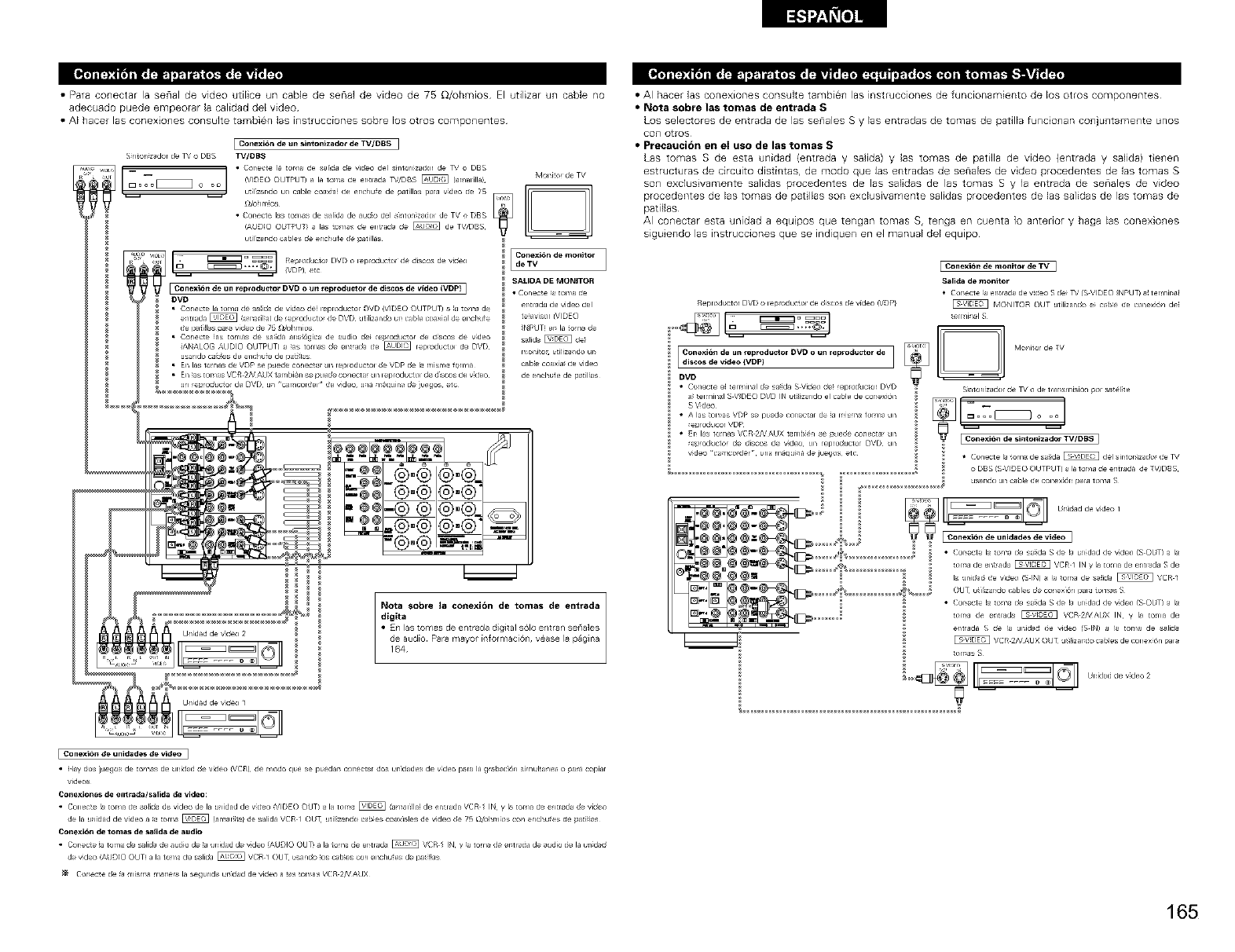
•Para conectar la senal de video utiEice un cable de senal de video de 75 _/uhmios El utilizar un cable no
adecuado puede empeorar la calidad del video
• AI hacer las conexiones consulte tambien Jasinstrucciones sobre los o'_ros componentes
[ Col_exi6ndeul_sintol_izador deTV/DBS [
S 1ton zador lie _/o DBS TV/DBS
,,_[1_ = /• Cor_e_:te la toma de sahda de wdeo del s_nton_zador de 7_,/ o DBS
_ L_°7_ o oo !VIDEO ©UTPUT)al ............... ea _J/DBS _ (amalilla/
J
,, patillas
_d°ilmi°s _
• Cor_ecte las torTlas de salida de audio del s:_lt_l_z_cJc_l de TV o DBS
!AklDIO OUTF_UT/ a las tomas de en!rad_ lie _ de TV/DBS
L_i_zar_cJc_cables lie el_chufe lie patillas
_[JL Ii:_ _ _'_ [Re¢_ x_ I 1° DVD ................. _e di co de vk_ex)
__ -- {VDP} etcIConexi6t_ de tin relXoducto_ DVD o ut_ _epr_Ju_t or lie discos de video (VDp} I
I)VD
• Cone_e la torla lie s_ida de video oe leploductoI DVD (VIDEO OUTPUT) aa tola de
entrada _ ] iafil ]) de ep odJcto lie DVD ]tilizando ur cJble coJxial de enc[ lie
de i,,_t]!las paa video de 75 _dohr fios
• Cone_e ias tot 1as de sada an_,_6gica de audio de} ep oli]_or de disc_*, de vdeo
{A[_ALOG ALDIO OUTPUT) ] ]s torls lie en rxSa de @ reploductol de DVD
usa 1do caB}es de e ic iufe de p ti]as
• En las tot 1as de VDR se puede conecta_ ]n leploductoI de VDP lie la r fisl_ a for la
• EI_ as tor 1as VCR 2NAUX t r ibi_n se p lede co lecta ]l_leploductoI de d 8cos de v deo
ul epoliJ_or de DVD u/ _rlcoldel de vdeo u/a _SqJil_alie juegos etc
M,)nito_ de TV
ioo-o°°. oo.o,ili°,v
SAI-II)A DE I_IONITOR
• Co_ecte _atoma de
er_tlada de video del
televisor (V_DEO
_NPLJT_ er_ la tom,, de
salid_, _ de_
came coaxia_ de video
de encht_f e de patil_as
Nota sobre la conexi6n de tomas de entrada
•AI hacer las conexiones consulte tambien las instrucciones de funcionamiento de los otros componentes
• Nota sobre las tomas de entrada S
Los seleclores de entrada de las se_lales S 'las entradas de tomas de patilla funcio_lan CO_lj_ltame_lte unos
co_] ot_os
•Precaucion en el uso de las tomas S
Las tomas S de esta unidad (entrada y salida) y las tomas de patilla de video (entrada y salida) t e_len
estructuras de circuito distintas, de modo que las entradas de senales de video procedentes de las tomas S
son exclusivamente salidas procedentes de las salidas de las tomas S y la entrada de seriales de video
procedentes de las tomas de pat Ilas son exdusivamente salidas procedentes de las salidas de las tomas de
patillas
AI CO_lectar esta unidad a equipos que tengan tomas S, te_lga en cuenta 1o anterior y haga las conexio_les
siguiendo las instrucciones que se indiquen en el manual del equlpo
[Con exibl_ de meail_ de TV ]
Salida de monitor
• Corvette }a er_trada de v_deo S lie} _,' (S V_DEO _NPUT) a{ t ermir_a_
Repr_sdt_ctor DVD Olel_lOductol deli_scoslievMeo!VDP/ _ [VIONITOR OUT utilizanlio e_ c_t_e de conex_6_ de_
__]_ €onoxi6n de un reprod_or DVD o_n rep_od_tor de _ _l_it°r de TV
DVD
• Conect ee_ _el minal de sa_ida S Video lie_ _eproliuctor D\'D S_r_tor_z_ cJc_l lie TV o de trar_siT_isiO_ pol sat_l_t e
a_ _el_il_al S V_DEO DVD IN utii_za_do el cable de cor_exi6n
• A las \'Dp de _a misma fo_m_ _
_ep_oducor VDP
_ep_oducto_ de discos de v_deo un reproductor DVD un
v_deo _:_J_er t,na r_uina de ju_jos etc • (_o_ecte la tor_a de sa_da _ liel sir_tomzalio_ de TV
o DBS IS VIDE O OUTPUT_ a la toma de entrada de _rV/DBS
_Jsar_cJc_un _t_le de conex_6n para toma S
I Con_ib_ de unidades de vid_ ]
• Hay dos iLJegos de _omas de unili_d lie vili_ (VCR} lie m_o qt,e se pt,edar_ _r_ectar dos urfidades de v_deo para la grat_ci,_n s_r_ul_anea o pa_ c_plar
videc_
Con_iones de em_da/salida de video:
• Con°ere _a toma de s_ilia d_ video de la u_fidad de v_deo _\'IDEO OUT) a la toma _ /amar_lla! de en_rada VCR / IN y I_,toma de entrada de video
de la u_fidad de video a _a _r_a _ _al_r_1_ de salida _CR / OUT _Jtil_z_r_cJc_c_b_es _xl_les de video lie 7_ _dol_r_fio*_ _ encl_ufes de _ati_i_s
Conexi_n de tomas de sa_ida de audio
• Cor_ecte _a tor_a de salid_ de audio de _a uniliad de v_deo _AUDIO OUT_ a la toma de er_trada _ VCR / IN y _a tor_ lie er_tl_da de _udio de la u n_d_li
de v_deo !ALJDIO OUT_ a la toma de s_lilia _ _ CR 1 OUT usa_do _os _b_es con el_chufes de i_ _i_as
_ Cor_ec_e lie _ _isl_a r_ar_era la segt,nda urfidad de vid_ a _s _om_s VCR 2IV ALJX
165
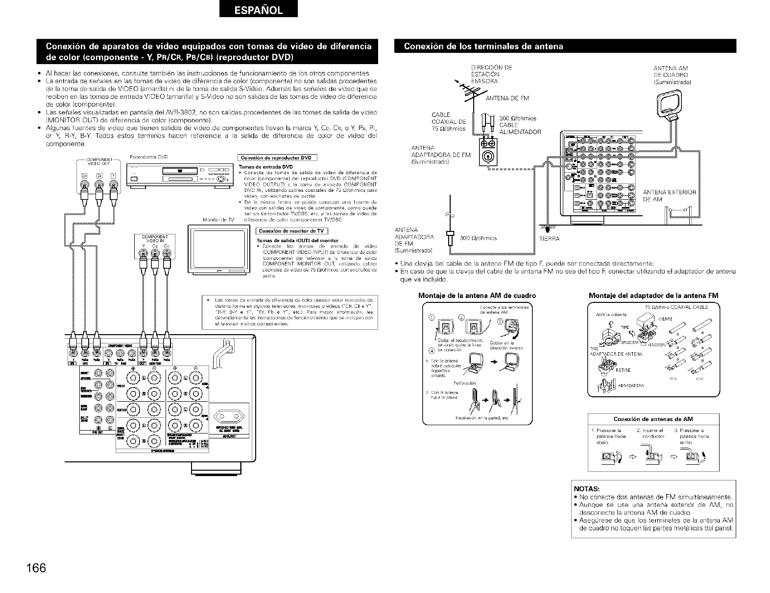
• AI hacer las conexiones, consulte tambi@n las instrucciones de funcionamiento de los otros componentes
• La er_trada de senales en las tomas de video de diferencia de color (componente) no son saWas procedentes
de la toma de salida de VIDEO (amarilla) ni de la toma de salida S-Video Ademas las seriales de video que se
reciben en las tomas de entrada VIDEO (amarilla) y S-Video no son saEidasde las tomas de video de diferencia
de color (componente)
• LassenaEesvisualizadasenpantalladelAVR-3802, nosonsalidasprocedentesdelastomasdesalidadevideo
(MONITOR OUT) de diferencia de color (componente)
• Algunas fuentes de video que tienen salidas de video de componentes Ilevan la marca Y, Ca, CR, o Y, Pb, Pi,
or Y, R-Y, B-Y Tudos estos terminos hacen referencia a la salida de diferencia de color de video del
componente
ReproductolDVD EConexi6n de rewodu_tor DVD ]
_@@
_E
@°®_
-@ @®°®-0
@® ®"
'°® ® ....-- ,
DIRECC}0N DE
ESTACl0N
_. EMISORA
ANTENADE FM
CABLE -t /]_1_ 300 [)/ohr'/_os
COAXIAL DE
, CABLE
78 _/o/m os ALIMENTADQR
ANTENA
ADAPTADORADEFM
{Su¥_[n[strado} !
ANTENA
ADAPTADORA TIERRA
DEFM
(Sumirlistrado)
ANTENA AM
DE CUADRO
(Su ¥_inistrado}
• Una daviia del cable de la antena FM de tipo F, puede ser conectada directamente
• En caso de que la clavija del cable de la antena FM no sea de1 tipo _ conectar utilizando el adaptador de antena
que va incluido
Montaje de la antena AM de cuadro
]_ anLenaAM
dlrec551_
_Lrpe,1;Se
e_tab_e
F'_do_aci_n
fii_ a la pa,ed --i_ -I_
lastalaciSn _r_ par_ er_
Montaje del adaptador de la antena FM
ICin exi6 n de antenas de AM
1 PeSlonela 2 Irserteel 3 Presionea
paa1ca/acia conductol palar_Jh_h
166
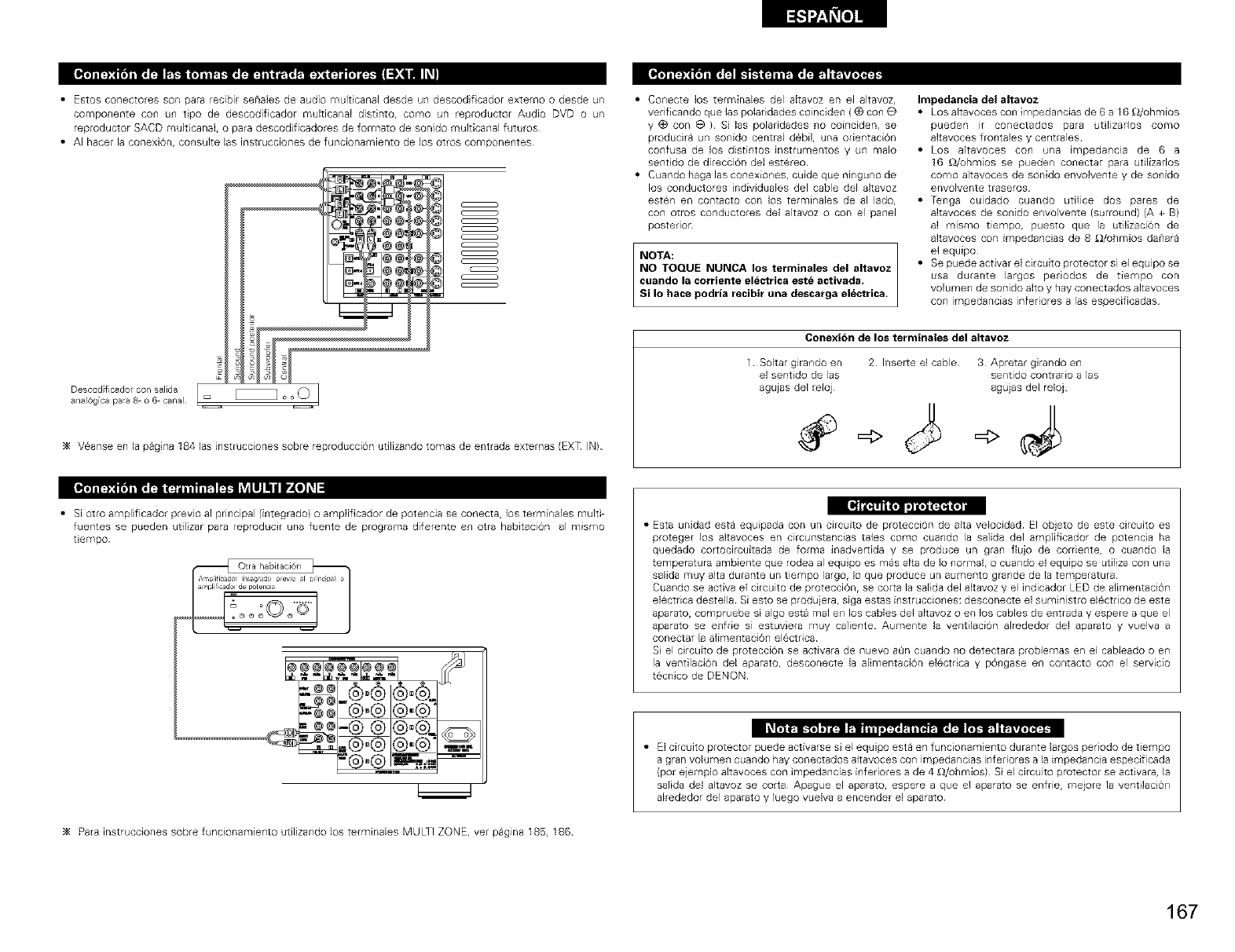
• Estos conectores son para recibil senales de audio mult canal desde un descod f cador extemo o desde un
componente con un tipo de descodificador multicanal distinto, co[no un reproductor Audio DVD o un
reproductor SACD multicanal, o para descodificadores de formato de sonido multicanal futuros
• AI Racer la conex 6n, consulte las instrucciones de funcionamiento de los otros componentes
Descod ficador con salida
a/al6gica para _ o 6 canal
c _
( _
( }
( _
c _
( _
_4 Veanse en la pagina 184 las instrucciones sobre reproducci6n utilizando tomas de entrada extemas (EXT IN)
• Conecte los terminales del altavoz en el altavoz,
verificando que las poladdades coinciden (_) con O
y (_) con e ) Si las polaridades no coinciden, se
producira un sonido central d6bil, una odentacion
confusa de los distintos instrumentos y un malo
sentido de direccion del estereo
• Cuando haga las conexiones, cuide que nmguno de
los conductores individuales del cable del altavoz
esten en contacto con los terminales de al lado,
con otros conductores del altavoz o con el panel
posterior
NOTA:
NO TOQUE NUNCA los terminales del altavoz
cuando la corriente electrica este activada,
Si Io hace podria recibir una descarga electrica.
Impedancia del altavoz
• Los altavoces con impedancias de 6 a 16 £_/ohmios
pueden ir conectados para utilizados como
altavoces frontales y centrales
• Los altavoces con ul-}a impedancia de 6 a
16 £_/_hmios se pueden conectar para utilizados
como altavoces de sonido envolvente y de sonido
envolvente traseros
• Tenga cuidado cuando utilice dos pares de
altavoces de sonido envolvente (surround) (A + B)
al mismo tiempo, puesto que la utilizaci6n de
altavoces con impedancias de 8 £_/ohmios danara
el equipo
• Se puede activar el circuito protector si el equlpo se
usa durante largos perodos de tiempo con
volumen de sonido alto y hay conectados altavoces
con impedancias infeRores alas especificadas
Conexi6n de los terminales del altavoz
1 Sokar girando en 2 Inserle el cable 3 Apretar grando en
el sentido de las sentido contrario alas
agujas del reloj agujas del reloj
1,40]=_1=1
• Si olro amplificador previo ai principal (integrado} o amplificador de potenc_a se conecta, los terminales multE
fuentes se pueden utilizar para reproducir una fuente de programa diferente en otra habitacion al mismo
tempo
• Esta unidad esta equipada con un circuito de proteccion de alta velocidad El ob}eto de este circuito es
proteger los akavoces en circunstancias tales como cuando la salida del amplificador de potencia ha
quedado cortocircuitada de forma inadverdda y se produce un gran fiujo de cordente, o cuando la
temperatura ambiente que rodea al equipo es mas alta de ]o normal, o cuando el equipo se utiliza con una
salida muy alta durante un tiempo largo, Io que produce un aumento grande de la temperatura
Cuando se activa el circuito de protecciOn, se corta la salida del altavoz y el indicador LED de alimentacion
elactdca destella Si esto se produjera, siga estas instrucciones: desconecte el suministro elactdco de este
aparato, compruebe si algo esta mal en los cables del altavoz o en los cables de entrada y espere a que el
aparato se enfde si estuviera muy caliente Aumente la ventilaciOn alrededor del aparato y vuelva a
conectar la alimentacion electrica
S el circuito de protecci6n se activara de nuevo aOn cuando no detectara problemas en el cableado o en
la ventilaci6n del aparato, desconecte la alimentaci6n elactdca y pongase en contacto con el servicio
tecnico de DENON
_4 Para instrucciones sobre funcionamiento utilizando los terminales MULTI ZONE, ver paglna 185, 186
• El circuito protector puede activarse s el equipo esta en funcionamiento durante largos periodo de tiempo
a gran volumen cuando hay conectados altavoces con impedancias infeRores a la impedancia especificada
(po_ eiemplo altavoces con impedancias infedores a de 4 £_/ohmios) Si el circuito protector se activara, la
salida del akavoz se corta Apague el aparato, espere a que el aparato se enfde, mejore la ventilaciOn
alrededor del aparato y luego welva a encender el aparato
167
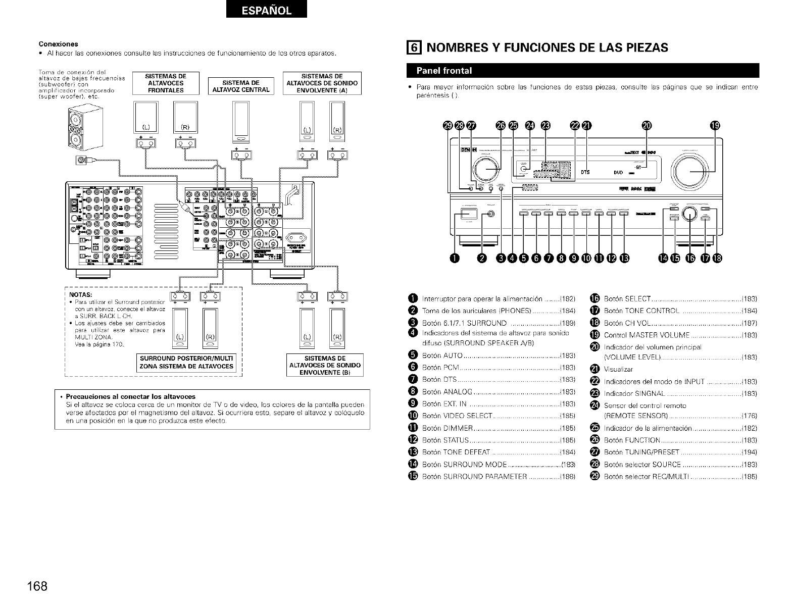
Oonexiones
• AI hacer las conexiones consulte las instrucciones de funcionamiento de los otros aparatos
To,mad.......i n o, j,[
altavoz de bajas frecuerlc as SISTEMAS DE
(subwoofer} con ALTAVOCES SISTEMA DE
amplificador rico porado FRONTALES ALTAVOZCENTRAL
(supe woofer), etc
F
INOTAS:
i
[] NOMBRES Y FUNCIONES DE LAS PIEZAS
• Para mayor informaciOn sobre las funciones de estas piezas, consulte las pagEnas que se indican entre
parsntesis ( )
c , ;@@
c _
c _
J°
t_J i_ _ ..........
I
• Para ut lizar e] Su round posterior
con uTsaltavoz conecte e altavoz
aSURR BACKLCH
i • Los aiustes debe set cambiados
para utlzar este a]tavoz para
MULTI ZONA
Vea la p_gila 20
SURROUND POSTERIOR/MULTI
ZONA SISTEMA DE ALTAVOCES I i
SISTEMAS DE
ALTAVOCES DE SONIDO
ENVOLVENTE (8}
• Precauciolles al collectar los altavoces
Si el altavoz se co]oca cerca de un monitor de TV o de video, los colores de ]a pantaNa pueden
verse afectados por el magnetismo del alIavoz Si ocurriera esto, separe el altavoz y colOquelo
en una posiciOn en la que no produzca este efecto
Interruptor para operar la alimentaciOn (182)
Toma de los auriculares (PHONES) .............. (184)
Boton 61/71 SURROUND ......................... (189)
Ind cadores del sistema de altavoz para sonido
difuso (SURROUND SPEAKER A/B)
Boron AUTO ................................................. (183)
Boron PCM ................................................... (183)
Boron DTS .................................................... (183)
Boron ANALOG ............................................ (183)
Boron EXIT IN .............................................. (183)
Boron VIDEO SELECT .................................. (188)
Boron DIMMER ............................................ (188)
Boron STATUS .............................................. (188)
Boron TONE DEFEAT ................................... (184)
Boron SURROUND MODE ..................................(183)
_} Boron SURROUND PARAMETER ................ (188)
Boron SELECT .............................................. (183)
Boron TONE CONTROL .............................. (184)
Boron CH VOL .............................................. (187)
Control MASTER VOLUME .......................... (183)
(VOLUME LEVEL) ......................................... (183)
_ Visualizar
_ Indicadores del modo de iNPUT .................. (183)
_ Indicador SINGNAL ...................................... (183)
_Sensor de] control remoto
(REMOTE SENSOR) ..................................... (176)
_ Indicador de la alimentaci6n ......................... (182)
_ Bot0n FUNCTION ......................................... (183)
_ Bot0n TUNING/PRESET ............................... (194)
_ Bot0n selector SOURCE .............................. (183)
_ Bot0n selector REC/MUkTI .......................... (188)
168
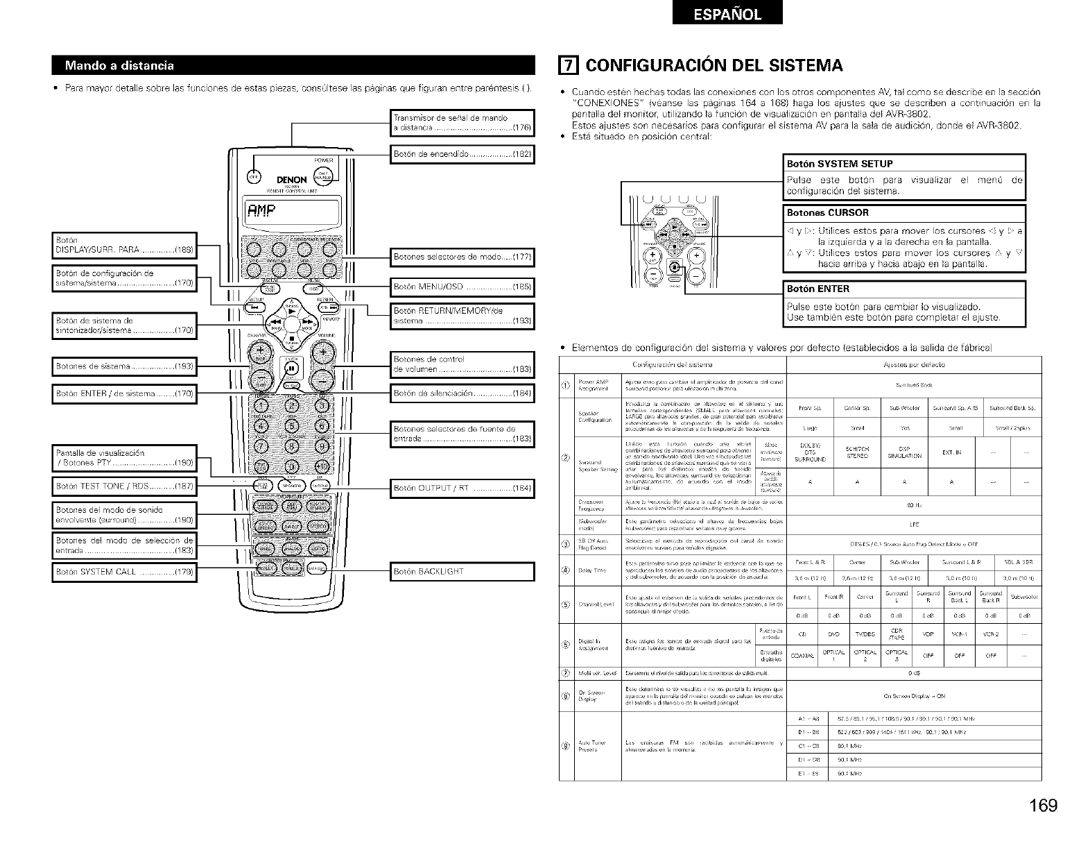
• Para mayor detalle sobre las funciones de estas piezas, co_sQItese las pagi_as que figuran entre parentesis ( )
III JBot6n MENU/OSD ................. (185} I
Bot6nRETURN/MEMORY/de ¸(193} I
III
I Bot61 SYSTEM CALL ............. (179} [
[] CONFIGURACION DEL SISTEMA
•Cuando esten hechas todas las coDexiones con los otros componentes AV, tal como se describe en la seccion
"CQNEXIONES" (veanse las paginas 164 a 168) haga los aiustes que se describen a co_ltinuaci6_l e_l la
pantalla del monitor, utilizando la funcion de visuaJizacion en pantalla del AVR-3802
Estos ajustes son necesarios para configurar el sistema AV para la sala de audicion, donde el AVR-3802
• Esta situado en posicion central:
/
Boton SYSTEM SETUP J
/
Pulse este boron para visualizar el rnenQ de
Botones CURSOR 1
] y 1': Utilices estos para mover los cursores y I a
la izquierda y a la derecha en la pantalla
, y ': Utilices estos para mover los cursores y
hacia arriba y hacia abajo en la pantalla
Boton ENTER
Use tarnbien este bot6_l para cornpletar el ajuste
Pulse este boton para cambiar Io visualizado
Elementos de configuracion del sistema y valores por defecto (establecidos a la salida de fabrica)
COlOr g Jracl_ i de siste _a Ajustes pot de ecto
AiJl_ ( r_ f,rJ c, ,_1 _1 Jmf iil a_ _r d( i,: r_ add _Jn,I S_r!_u :j BJk
lanan_ :ri( prrdl ,1( (SMALL I1_ _c_ ,orr I Fr_r_l P C_nl(, Sf _b_/ Ir ,_m r_d _ A_B S,_r! _dBakS I
,:r d(r_r_ !a orp: _,, d( I rid #_ (,It
omH! a i:r _ J: ,ll_,(×,r _h _U '_ p_ _dl( ' rrr T
par_ _i Ih_r ,r _xJ_ _( (>n kJ(
irl _r_ H_rl xn,ls Jl ,is
prlnl_ vh,_ H _plh, r! _l I, ql s_ Fr _r:_ L & H ml_r 115 _ Ir ,_m r_d L & P _L &
...............r
_1 h,nd a dl ta,dl d_,l,u,dd _d,_p _
B E
Las :rls_ras F,I s_n iHsl,,li:r_,nl C _
I r _ r r
El E or,,
169
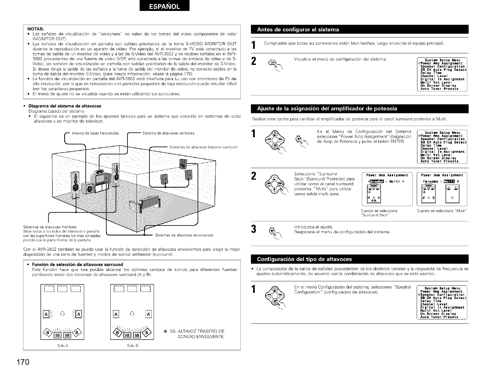
NOTAS:
• Las senales de visualizaci6n de r'on-screen" no salen de los tornas del video cornponente de color
(MONITOR OUT)
• Las senabs de visualizaciOn en pantalla son salidas priodtadas de la tome S-VIDEO MONITOR OUT
durante la reproducci6n en un aparato de video Pot eiemplo, si el monitor de TV esta conectado alas
tomes de salida de un monitor de video y alas de S-Video del AVR-3802 y se reciben senabs en el AVR-
3802 procedentes de una fuente de video (VDR etcl conectada alas tomas de entrada de video y de S-
Video, las senales de visualizaci6n en pantalla son salidas pnodtar as de la salida del monitor de S-Video
Si desea dkigk la salida de las senales ala toma de salida del monitor de videor no conecte cables en la
tome de salida del monitor S-Video, (pare mayor informaciOn, vease la pagina 176)
• La funci6n de visualizaciOn en pantalla del AVR-3802 esta disenada pare su uso con monitores de TV de
alta resoluciOnr por Io queen televisiones con pantallas pequenas de baja resoluciOn-puede resultar dificil
leer los caracteres pequenos
• El menG de ajuste no se visualiza cuando se estan utilizando los auriculares
• Diagrarna del sistema de altavoces
Diagrama basico del sistema
•El siguiente es un ejemplo de los apuntes basicos pare un sEstema que cons_ste en sistemas de ocho
altavoces y un monitor de televisor:
de ajas frecuendas
l
S
iiiiiiiiiiiiiiiii ii ii;
i!ii!i!!ii!i!iii i ii!i!i!ii!ii!i!!!i!i!!ii!i!ii!iiii ii ii ii ii!i! i
f
Sistemas de 81tavoces frog/tales
Sit0e estos a los I_dos de1televisor o pantalla
con las superficies frOT_t_l_slOSf_l_Saline_das
pos[ble con la parCefrontal de la pantalla
S[stemas de alt_voces envolventes
Con el AVR-3802 tambien se puede usar la funcion de seleccion de altavoces envolventes pare elegir la mejor
disposiciOn de una serie de fuentes y modos de sonido ambiental (surround)
•Funcidn de seleccidn de altavoces surround
Esta funcion hace que sea posible alcanzar los op6mos campos de sonido para diferentes fuentes
cambiando entre dos sistemas de altavoces surround (A y B)
;----' [----' F---'
L---" L---" L---"
/'_. \1/ \1/ /'X SB: ALTAVOZ TRASERO DE
SONIDO ENVOLVENTE
Solo A Solo B
I
2
Compruebe que todas las conexiones estan bien hechas, luego encienda el equipo principal
Visualice el men0 de configuraciOn del sistema _ syetem Setu_ Menu
_Power Amp Assilnment 1
Speaker Confllura_lon
SB CHAuto FlaK Detect
Delay Time
Channel Level
DlKltal In Aeel=nment
Multi VoL Level
On Screen Display
Auto Tuner Presets
Realice este aiuste para cambiar el amplificador de potencia para el canal surround posterior a Multi
En el MenO de Configuraci6n del Sistema _ Syetem Setup Menu
se]eccione "PowerAmpAssignment"(AsignaciOn _Power AmpAeel_nment 1
Speaker Coflflluratlo_
de Amp de Potencia)y pulseelboron ENTER s8 CHAuto Flel Detect
Delay Time
Channel Level
Oliltal In Aeel_nment
Multi Vol. Level
On Screen Display
Auto Tuner Presets
2Seleccione "Surround
Back"(Surround Posterior) para
utilizer como el canal surround
postedo_, "Multi" pare ut lizar
como salida multi zone P:werAm A:::::o:nt
Cuando se se]ecoio_/a
"Sulround Back"
Power Amp AseIKnment
Cua/do se seleco[ona "Muir
Introduzca el ajuste
Reaparece el menL_de configuracion del sistema
• La composici6n de la salida de seflabs procedentes de los distintos canales y la respuesta de frecuencia se
ajustan automa6camente, de acuerdo con la combinaciOn de altavoces que se este usando
En el men0 ConfiguraciOn del sistema, seleccione "Speaker sye_em Setup Menu
Configuration" (configuraci6n de altavoces) Power Amp As=I =nmen_ 1
2Speaker Confiluration
SB CH Auto Fle_ Detect
Oeley Time
Channel Level
DIIItal In Alslgnment
Multi Vol. Level
On Screen Disglay
Auto Tuner Presete
170
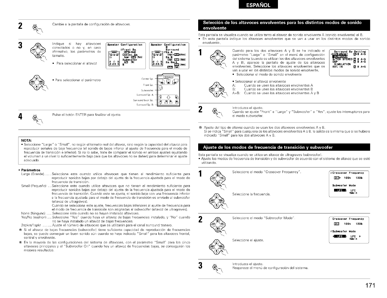
Cambie ala pantafla de configuracion de altavoces
Indique si hay akavoces Spemker Confiiuration
conectados o no y, en case _Front Sp*
afirmativo, los parametros de _ _
tamano _ Center sD'
Subwoofer
•Para seleccionar el altavoz _ [_
•Para se+eccionar el parametro
Speaker C_nf iIuretion
EPS_4_ _
Sp, Beck
Center Sp
F_ont Sp
Subwoofer
SumXJl_d Sp A
SUlroUr_d Im_ck Sp
S_mound Sp B
Pulse el boron ENTER para finalizar el aiuste
NOTA:
•Seleccione "Large" o "SmalF', no seg6+l e[ taTnano real del altavoz, sine segan la capacidad del altavoz pare
reproducir sena+es de baia frecuencia (el SO+lidOde baios inferior al ajuste de frecuencia pare el mode de
frecuencia de transicion e inferior} Si no Io sabe, trate de comparar el sonido en ambos aiustes (ajustando
el volumen a un nivel Io suficientemente ba}o pare que los altavoces no se darien) pare determiner el aiuste
adecuado
Esta pantalla se visualize cuando se utiliza tanto el altavoz de sonido envolvente A (sonido envolvente) el B
•En esta pantalla indique los altavoces envolventes que se van a user en los dist ntos modes de sonido
envolvente
Cuando pare los dos altavoces A y Bse ha indicado el
parametro "Large" o "Small" en el menO de configuraciOn
de1 sistema (cuando se utilizan los dos akavoces envolventes
A y B), aparece la pantalla de ajuste de los altavoces
envolventes Seleccione los alLavoces envolventes que se
van a usar en los distintos modes de sonido envolvente
= Se+eccionar el mode de sonido envolvente
Surround Sp Setting
_REO [] 8 A+B
DSP [] B A+B
SIMULATION
EX_ IN [] B A+B
•Seleccionar el altavoz envolvente
A: Cuando se usen los altavoces envolventes A
B: Cuando se usen los altavoces envolventes a
A+B: Cuando se usen los altavoces envolventes A y B
Introduzca el ajuste
Cuando se aiuste "Front" a "Large" y "Subwoofer" a "Yes", ajuste Jos interruptores para
el mode subwoofer
Ajuste del tipo de altavoz cuando se usan los dos altavoces envolventes A y B
Si se indica "Small" pare cua+quiera de los altavoces envolve+ltes A o B, la salida es la misma que slse hubiera
indicado "Small" para los dos altavoces A y B
Esta pantalla se visualize cuando se utiliza un altavoz de dtragraves {subwoofer)
• Ajuste los modes de frecuencia de trans cion y de subwoofer de acuerdo con el sistema de altavoz que se este
utilizando
• Parametros
Large (Gra+lde) Seleccione este cuando utilice altavoces que tienen el rendimiento sufcie+lte para 1
reproducir sonidos bajos per debaio del ajuste de +a frecuencia ajustada pare ei mode de
frecuencia de transicion
Sinai+ (Pequerio) Seleccione este cuando utifice altavoces que no tienen el rendimiento suf cJente para
reproducir sonidos bajos per debaio del ajuste de la frecuencia ajustada pare ei mode de
frecuencia de transiciOn Cuando este se ajusta, el sonido bajo con una frecuencia infer or
a la frecuencla ajustada pare el mode de frecuencia de transicion es enviado al subwoofer
(altavoz de ultragraves)
Cuando se selecciona este a}uste, frecuencias baias inferiores al ajuste de frecuencia para
el mode de frecuencia de transiciOn son aslgnadas al subwoofer {altavoz de u+tragraves)
None (Ninguno) Se+eccione este cuando no se hayan instalado altavoces
Yes/No (oui/non)Seleccione "Yes" cuando haya un a+tavoz de bajas frecuencias instalado, y "No" cuando
no se haya instalado un altavoz de baias frecuencias _,
2spkrs/1 spkr .......... Ajuste el nQmero de alLavoces que se utilizaran para el canal surround trasero
Si el altavoz de bajas frecuencias (subwoofer) tiene suf ciente capacidad de reproduccion de frecuencias
bajas, se puede conseguir un buen sonido aQn cuando se haya indicado "Small" pare los altavoces frontal,
central y envolvente
En la mayoda de las configurac_ones de+ sistema de altavoces, con el parametro "Small" pare los cinco
altavoces principales y el 'rSubwoofer On" cuando hay un altavoz de frecuencias bajas, se conseguiran los
meiores resultados
Seleccione el mode "Crossover Frequency"¸
Seleccione 18 f_ectlencia
_Cros_over Frequency
_lOOHz 120_
Subwoofer Mode
_: LFE
_aln
Seleccione el mode "Subwoofer Mode"
Seleccione el ajuste
ICrossove_ Frequency
lOOHz 120_
_Sgbwoofer Mode
4_m_--I_: LFE
-Main
3Introduzca el ajuste
Reaparece el menO de configuracion del sistema
171
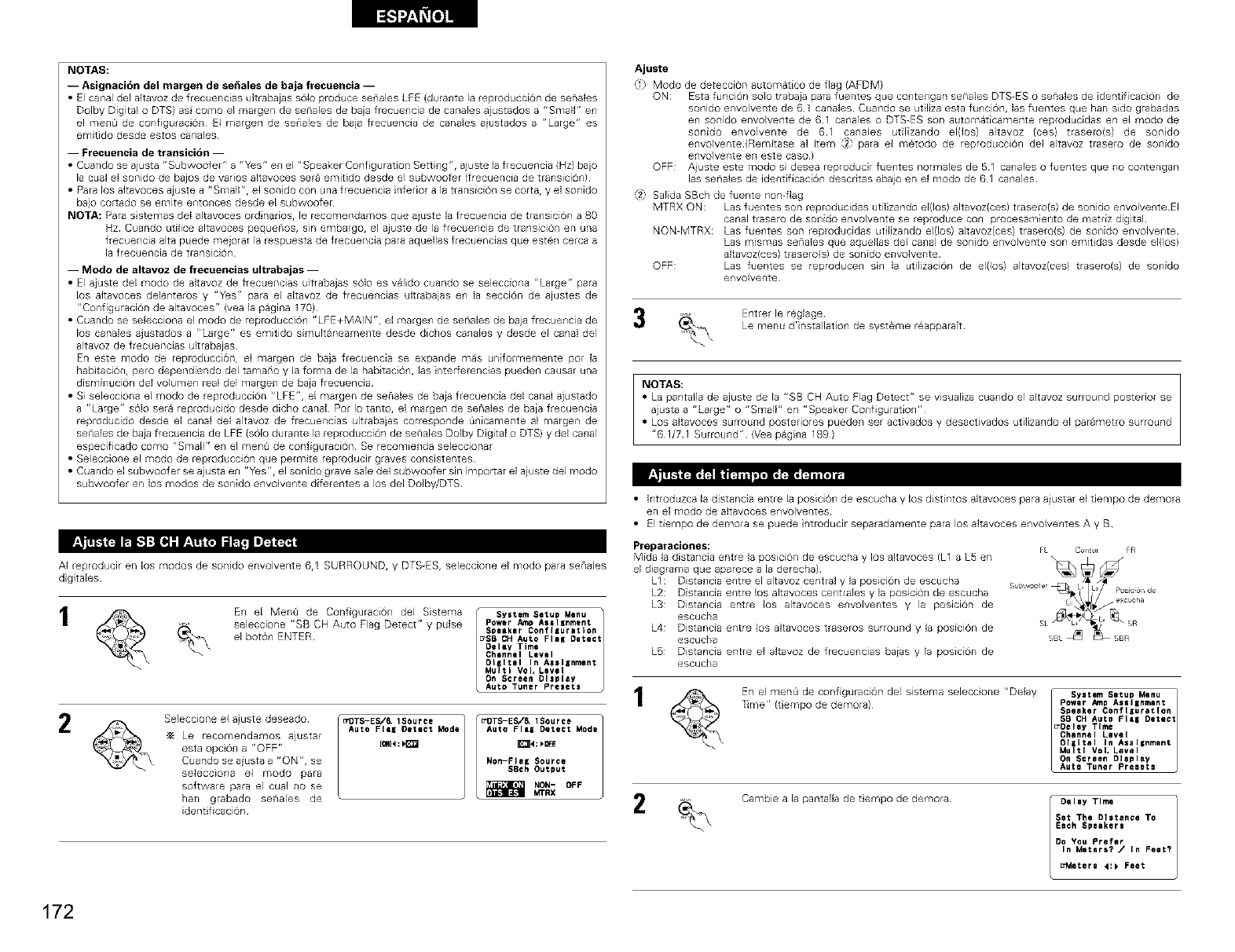
NOTAS:
-- Asignacion del margen de se_ales de baja frecuencia --
• El canal del altavoz de frecuencias ultrabajas s61o produce sellales LFE (durallte la reproducciOn de senales
Dolby Digital o DTS) as cored el margen de senabs de baia frecuencia de canaJes aiustados a "Small" en
el menO de configuraci0n El margen de senales de baja frecuencia de canales aiustados a "Large" es
emitido desde estos canabs
-- Frecuencia de transici6n --
• Cuando se ajusta "Subwoofer" a 'rV_s" en el "Speaker Conf guration Setting", ajuste la frecuencia (Hz) ba}o
la cual el sonido de bajos de vados altavoces sere emitido desde el subwoofer (frecuencia de transici6n)
• Pare los aJtavoces ajuste a "SmaJl"r el sonido con una frecuencia inferior a la transici0n se cotter y el sonido
bajo cortado se emite entonces desde el subwoofer
NOTA: Pare sistemas del altavoces ordinarios, le recomendamos que ajuste la frecuencia de transicion a 80
Hz Cuando utilice altavoces pequenos, sin embargo, el ajuste de la frecuencia de transici6n en una
frecuencia alta puede mejorar la respuesta de frecuencia para aquellas frecuencias que eaten cerca a
la frecuencia de transici0n
-- Modo de altavoz de frecuencias ultrabajas --
• El ajuste del modo de altavoz de frecuencias ultrabajas s01o es valido cuando se selecciona "Large" pare
los akavoces delanteros y "Yes" pare el altavoz de frecuencias ultrabajas en la seccion de ajustes de
"Configuracion de altavoces" (vea la pagina 170)
• Cuando se selecciona el modo de reproducciOn "LFE+MAIN", el margen de senales de baja frecuencia de
los canales ajustados a "Large" es emitido simuJtaneamente desde dichos canales y desde el canal del
altavoz de frecuencias ultrabajas
En este modo de reproducciOnr el margen de baja frecuencia se expande mas uniformemente pot la
habitaci6n, pard dependiendo del tamario y la forma de la habitaci0n, las nter_erencias pueden causer una
disminuci6n del volumen real del margen de baia frecuencia
• Si selecciona el modo de reproducci6n "LFE", el margen de senales de baja frecuencia del canal ajustado
a "Large" s01o sere reproducido desde dicho canal Por Io tanto, el margen de senales de baia frecuencia
reproducido desde el canal del altavoz de frecuencias ultrabajas corresponde Onicamente al margen de
senales de baja frecuencia de LFE (s01o durante la reproducci6n de senabs Dolby Digital o DTS) y del canal
especificado cored "SmalJ" en el menO de configuraciOn Se recomienda sebccionar
• Seleccione el modo de reproducci6n que permite reproducir graves cons4stentes
• Cuando el subwoofer se ajusta en "Y_s 'r, el sonido grave sale del subwoofer sin imporlar el aiuste del modo
subwoofer en los modos de sonido envolvente diferentes a los del Dolby/DTS p._ F'J[IF_ t_lB FI= _
AI reproducir en los modos de sonido envolvente 6,1 SURROUND, y DTS-ES, seleccio_e el modo para senales
digitales
En el MenQ de Configuraci6n del Sistema
seleccione "SB CH Auto Flag Detect" y pulse
el boron ENTER
System Setup Menu t
Power Amp AsslEnment
Speaker Configuration
_SB CH Auto FlaB Detect
Delay Time
Channel Level
OIIItel In Assignment
Multi Vol, Level
On Screen DIsplay
Auto Tuner Presets
2Seleccione el a)uste deseado
Le recomendamos ajustar
esta opcion a "OFF"
Cuando se aiusta a "ON", se
selecciona el modo pare
software para el cuaJ no se
hun grabado senales de
identificaci6n
_DTS-ES/_ 1Source
Auto FIlE Detect Mode
[_4:_
_DTS-ES/& 1Source
Auto FIlE Detect Mode
Non-Fie= Source
SBch Output
_ NON- DFF
UTRX
Ajuste
,_1_Modo de deteccion automatico de flag /AFDIVi)
ON: Esta funci6n solo trabaja pare fuentes que contengan senabs DTS-ES o senales de identificaci6n de
sonido envolvente de 61 canales Cuando se utiJiza esta funci6n, las fuentes que hun sido grabadas
en sonido envolvente de 61 canales o DTS-ES son automaticamente reproducidas en el modo de
sonido envolvente de 61 canales utilizando el(los) altavoz (ces) trasero(s) de sondo
envolvente (Remitase al item _2} pare el metodo de reproducci6n del altavoz trasero de sonido
envolvente en este caso)
OFF: Ajuste este modo si desea reproducir fuentes normales de 51 canales o fuentes que no contengan
las senales de identificaci6n descritas abajo en el modo de 61 canales
,_2 Salida SBch de fuente non-flag
MTRX ON: Las fuentes son reproducidas utilizando el(los) akavoz(ces) trasero(s) de sonido envolvente El
canal trasero de sonido envolvente se reproduce con procesamiento de matdz digi[al
NON-MTRX: Las fuentes son reproducidas utilizando el(los) akavoz(ces) trasero(s) de sonido envolvente
Las mismas senales que aquellas del canal de sonido envolvente son emit das desde el(los)
altavoz(ces) trasero(s) de sonido envolvente
OFF: Las fuentes se reproducen sin la utilizaci6n de el(los) altavoz(ces) trasero(s) de sonido
envolvente
Entrer le r6glage
Le menu d'installat o_ de systeme raapparatt
NOTAS:
• La pantalia de ajuste de la "SB CH Auto Flag Detect" se visualize cualldo el akavoz surroulld posterior se
ajusta a "Large" o "Small" en "Speaker Configuration"
• Los akavoces surround posteriores pueden ser activados y desactivados utilizando el parametro surround
"61/71 Surround" (Veapagina 189)
• Introduzca la distancia entre la posicbn de escucha y los distintos altavoces para ajustar el tiempo de demora
en el modo de altavoces envolventes
• El tiempo de demora se puede introducir separadamente para los altavoces envolventes A y B
Preparaciones:
Mida la distancia entre la posici6n de escucha y los altavoces (L1 a L5 en
el diagrama que aparece a la derecha)
LI: Distancia entre el altavoz central y la posiciOn de escucha
L2: Distancia entre los akavoces centrales y la posici6n de escucha
L3: Distancia entre los altavoces envolventes y la posicion de
escucha
L4: Distancia entre los altavoces traseros surround y la posicion de
escucba
LS: Distancia entre el altavoz de frecuencias baias y la posici6n de
escucba
En el menQ de configuracion del sistema seleccione "Delay / SYstem Setup Menu t
_me" (tiempo de demote) Power _,np Asgilnment
Speaker ConflEuretlon
SB CH Auto Flee Detect
_Deley Time
Channel Level
Digital In Assignment
Multi Vol* Level
On Screen Display
Auto Tuner Presets
2Cambie a la pantalla de tempo de demora Delay Time
Sat The Distance To
Each Speaker=
Do You Prefer
In Meters? /In Feet?
_Meters 41_ Feet
172
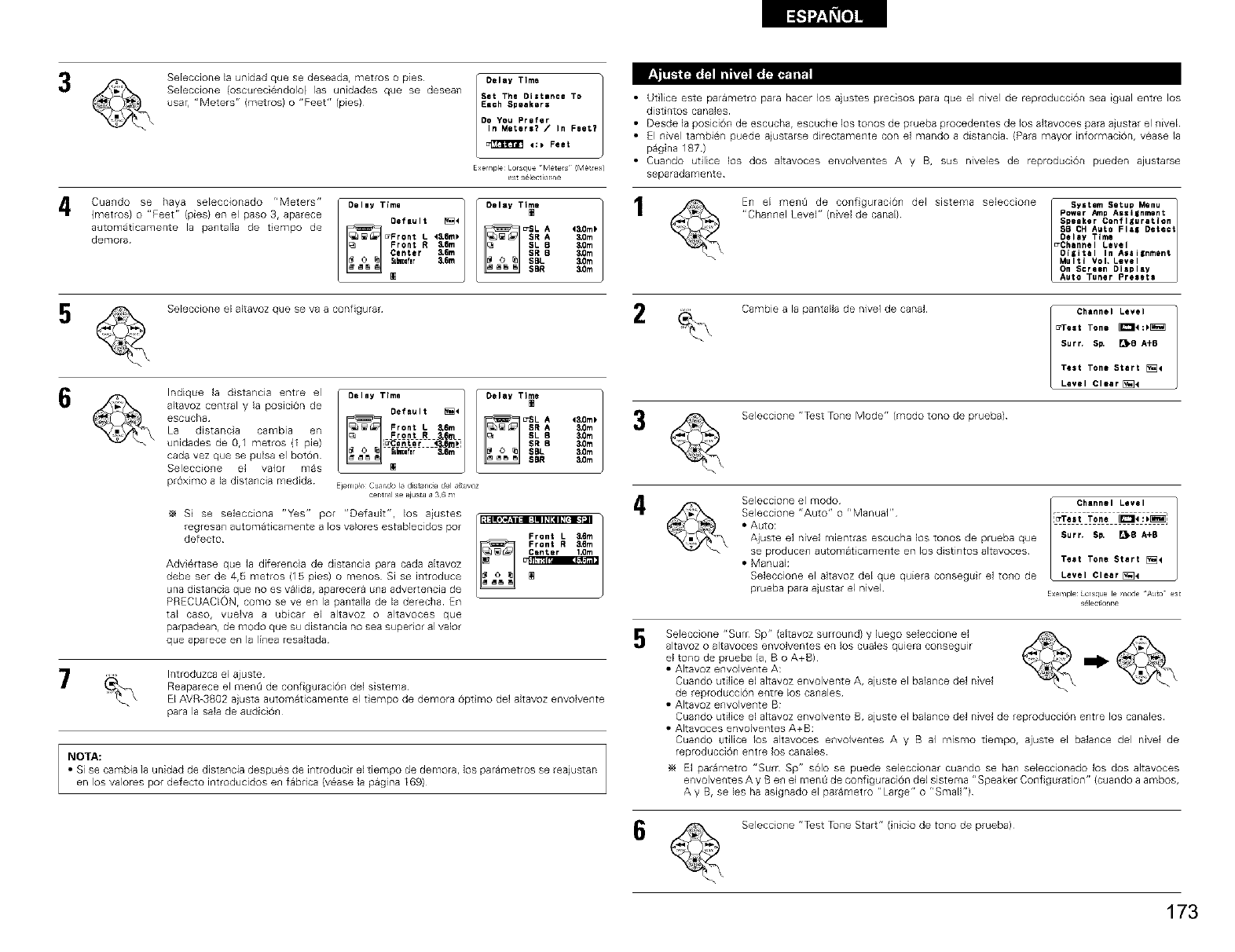
_ _ _I
3Sebccione la unidad que se deseada, metros o pies
Sebccione (oscureciendolo) las unidades que se desean
usar, "Meters" (metros)o "Feet" (pies)
Delay Time
Set The Distance To
Each Speakers
DO You Prefer
In Meters? /In Feet?
4:_ Feet
E×ernpleLorsqueMet_s!Me_es/
•Ut ]ice este parametro para hacer los ajustes precisos para que el nivel de reproducciOn sea igual entre los
distintos canales
• Desde la posici0n de escucha, escuche los tunas de prueba procedentes de los altavoces para ajustar el nivel
• El nivel tambien paede ajustarse directamente con el mando a distancia (Para mayor informacion, vease la
pagina 187)
• Cuando utilice los dos altavoces envolventes A y B, sus niveles de reproduciOn pueden ajustarse
separadamente
"Cu d°sehay seecc° ad°rMe'ers°'"T'm']l°''YT"1
(metros) o "Feet" (pies) en el paso 3, aparece Oefault _4
automaticamente la pa_talla de tempo de
43,om_
4s, IIm _
demora _Front L 3,Ore
Front R SSm t0m
Center 3,6m 3_m
Su_Iflr 3,Bm _,Om
[]
2
Sebccione el altavoz que se va a configurar
altavoz central y la posici6n de Default _4
escucha _ _ u'SL A 43.0m_
La distanca cambia en Front L 3.6rn SR A _m
F_gpt R 3,60L SL B
unidades de 0,1 metros (I pie) lu'Center <_m_' SR B3,Ore
cada vez que se pu[sa el baton i=hr &6m ' SBL 80m
SBR 3.0m
Selecc[o_e el valor mas
proximo a la distancia medida E}e_lpk_ Cu_l,do E, distan_ _ del tJvoz
cer tl I se ajutJ a "_G _
S se selecciona "Yes" par "Default', los ajustes
regresan automaticamente a los valores establecidos par
defecto Front L 3.6m
4
5
Adviertase que la diferencia de distancia para cada akavoz
debe ser de 4,5 metros (15 pies) o menus Si se introduce
una distancia qua no es valida, aparecera una advertencia de
PRECUACIONr coma se ve en la pantafla de la derecha En
tal caso, vuelva a ubcar el altavoz o altavoces que
parpadean, de modo que su distancia no sea superior al valor
qua aparece en la linea resaltada
En el men_ de configuraci6n del sistema seleccione I S_t.mSetu_Menu ]
"Channel Level" (_ivel de canal)¸ Power _p Assilnment
Speaker Con_lluratlan
$5 CH Auto Flal Detect
Delay Time
_Chan_el Level
Digital In Assi_nmQnt
Multi VoL Level
On Scraen Display
Auto Tuner Presets
Introduzca el ajuste
Reaparece el men0 de configuraci6n del sistema
El AVR-3802 ajusta automaticamente el tempo de demora 6ptmo del altavoz envolvente
para la sala de audici6n
NOTA:
•Si se cambia ]a unidad de distancia despues de illtroducir el tiernpo de demora, los pararnetros se reajustan
en los valores par defecto introducidos en fabrica (vease la pagina 169)
Cambie a la pantalla de nivel de canal
Seleccione "Test Tune Mode" (modo tuna de praeba)
Channel Level
_'Test Tone _4:_
Surr. Sp. _B A+B
Test Tone Start [_4
Level Clear D_4
Seleccione el modo
Seleccione "Auto" o "Manual"
• Auto:
Ajuste el nivel mientras escucha los tunas de prueba que
se produce_ automat came_te en los distintos altavoces
• Manuah
Seleccione el akavoz del que quiera co_seguir el to_o de
prueba para ajustar el nivel
IChannel Level
Surf, SP, _B A+B
Test Tone Start [_4
Level Clear [_4
EXln_le orsqu le _od /_Jto Sl
Ictonr_
Seleccione "Surr Sp" (altavoz surround) y luego seleccione el
altavoz o alLavoces envolventes en los cuales qulera consegulr
el tuna de prueba (at B o A+B) I_
• Altavoz envolvente A:
Cuando utifice el altavoz envolvente A, ajuste el balance del nivel
de reproducciOn entre los canales
• Altavoz envolvente B:
Cuando utifice el altavoz envolvente B, ajuste el balance del nivel de reproducciOn entre los canales
• Altavoces envolventes A+B:
Cuando utflice los altavoces envolventes A y B al mismo tiempo, ajuste el balance del nivel de
reproduccion entre los canales
El parametro "Sum Sp" s01o se puede sebccionar cuando se ban sebccionado los dos altavoces
envolventes A y Ben el ment_ de configuracion del sistema "Speaker Configuration" (cuando a ambos,
A y B, se les ha asignado el parametro "Large" o "SmaW')
Seleccio_e "Test Tune Start" (inicio de to_o de prueba)
173
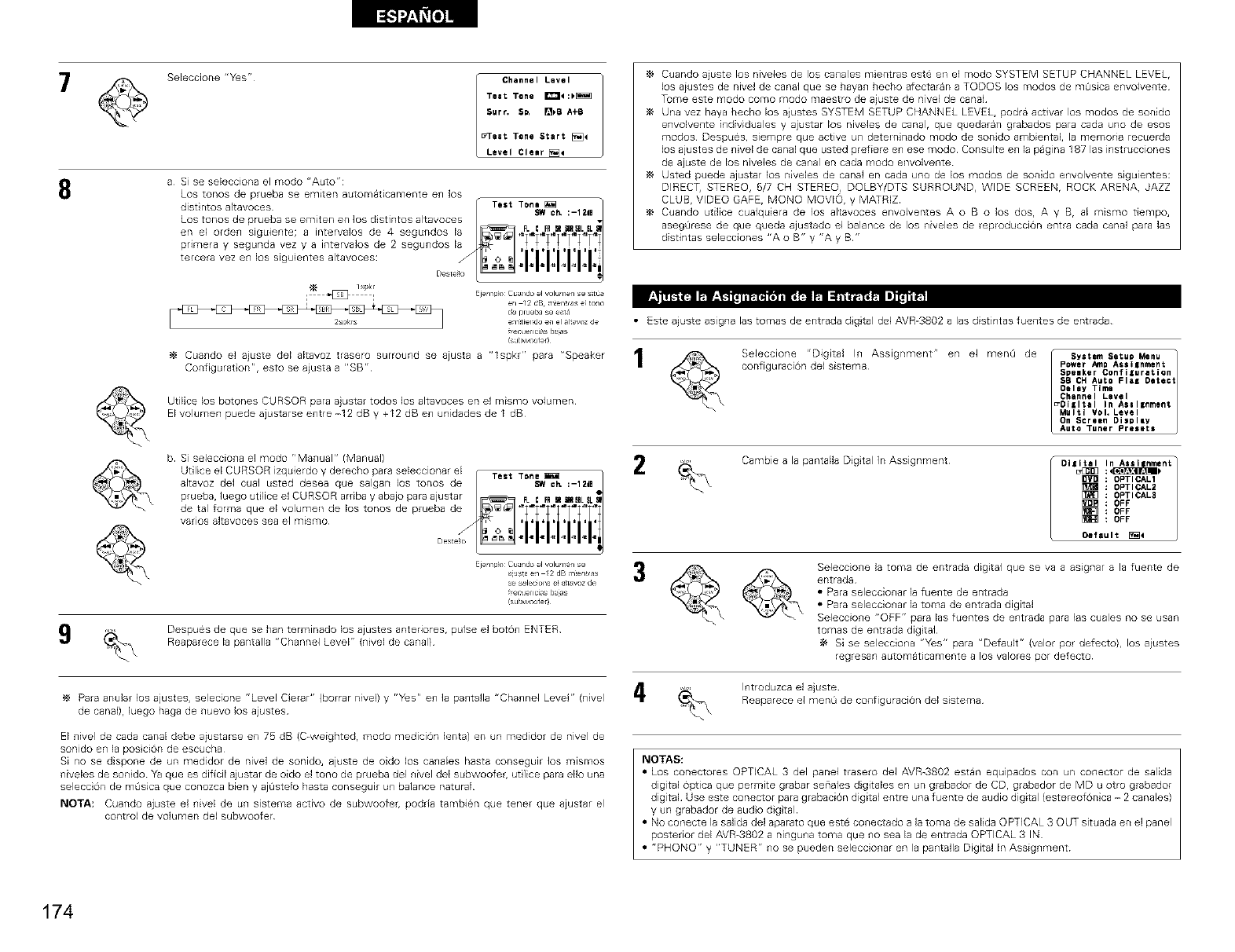
8
Seleccione "Yes"
Channel Level
Teat Tone I_:)_
Surf. S_ []_B A+B
_eat Tone Start [_4
Level Cleer[!_
a Si se selecciona el modo "Auto":
Los tonos de prueba se emiten automaticamente e_l los
Cuando ajuste los niveles de los canales mientras este eli eEmodo SYSTEM SETUP CHANNEL LEVEL,
los aiustes de nivel de canal que se hayan hecbo afectaran a TODOS los modus de m0sica e_wolvente
Tome este modo como modo maestro de ajuste de hive1 de canal
Una vez haya becho los ajustes SYSTEM SETUP CHANNEL LEVEL, podra activar los modus de sonido
envolve_te individuales y ajustar los niveles de canal, que quedaran grabados para cada uno de esos
modus Despues, siempre que active u_ deteminado modo de sonido ambientaL la memoria recuerda
los ajustes de _fivel de canal que usted prefiere e_ ese modo Consulte e_ la pagina 187 las instrucciones
de ajuste de los niveles de ca_al en cada modo envolvente
Usted puede ajustar los niveles de canal en cada uno de los modus de sonido e_wolvente siguientes:
DIREC% STEREO, 5/7 CH STEREO_ DOLBY/DTS SURROUND, WIDE SCREEN, ROCK ARENA, JAZZ
CLUB, VIDEO GAFE, MONO MOVIOr y MATRIZ
Cuando utilice cualquiera de los alLavoces envolventes A o B o los dos, A y B, al mismo tiempo,
asegQrese de que queda ajustado el balance de los niveles de reproduccion entra cada canal para las
distintas selecciones "A o B" y "A y B"
lspl<l
i @ ] Ejemp_° Cuando el volumen se s_tO_
en 12 dB m_en_r_s eFto_lo
de prueba se est_
2spkrs em:tiendo e_l el altavoz de
ffecueYicias ba_as
subw,oote_
Cuando el ajuste del altavoz trasero surround se ajusta a "lspkr" para "Speaker
Configurat on", esto se ajusta a "SB"
UtiEce los botones CURSOR para ajustar todos los altavoces en el mismo volumen
EIvolumen puede ajustarse entre -12 dB y +12 dB en unidades de I dB
b Si selecciona el modo "Manual" (Manual)
Ejemp_o Cuando el volumen se
_lus_a en /2 dB m_en_ras
se seleck_na e_a_t_voz de
ffecue_cias betas
subw,oote_
Despues de que se ban terminado los ajustes anteriores, pulse el boron ENTER
Reaparece la pantalla "Channel Level" (nivel de canal)
Para andar los ajustes, selecione "Level Clerar" (borrar nivel) y r'y_sr' en la pantalla "Channel Level" (nivel
de canal), luego haga de nuevo los ajustes
El nivel de cada canal debe aiusta_se en 75 dB (C-weightedr modo medicion lenta) en un medidor de nivel de
sonido en la pus cion de escucba
Si no se dispone de un medidor de nivel de sonido, ajuste de oido los canales hasta consegulr los mlsmos
niveles de sonido Ya que es dificil ajustar de oido el tono de prueba del nivel del subwoofeg ut lice para ello una
seleccion de m0sica que conozca bien y aj0stelo hasta consegulr un balance natural
NOTA: Cuando ajuste el nivel de un sistema activo de subwoofeg podria tambien que tenet que ajustar el
control de volumen del subwoofer
• Este ajuste asigna las tomas de entrada digtal del AVR-3802 a las distintas fuentes de entrada
Seleccione "Digital In Assignment" en el men0 de [ System Setu_ Menu
co_figuraci6n de[ sistema Power Am_ Assilnment
_e_e_ C_i_atien
S_ _ _t_ _ _tect
_e_a_ Tl_e
_n_e_ La_e_
_l_t_ _n _a_|_e_
_l V_ _e_e_
_n _e_ee_ _i$_
_e_e _e_ _e_e_
2Cambie a la pantalla Dig tal In Assignment Dllit_al.,LU_U:<_lnAlll nment
OPTICAL1
OPTICAL2
[_] OPTICAL3
OFF
OFF
OFF
Oel"auIt_4
Seleccione la toma de entrada digital que se va a asignar a la fuente de
entrada
a Para seleccionar la fuente de entrada
a Para seleccionar la toma de entrada digital
Seleccione "OFF" para las fuentes de entrada para 1as cuales no se usan
tomas de entrada digital
Si se selecciona "Yes" para "Default" (valor pot defecto), los aiustes
regresan automaticamente a los valores por defecto
i_ Introduzca el ajuste
Reaparece el men0 de configuracion del sistema
NOTAS:
a Los conectores OPTICAL 3 del panel trasero del AVR-3802 estan equipados con un conector de salida
digital optica que permite grabar seriales digitales en un grabador de CDr grabador de MD u otro grabador
digital Use este conector para grabacion digital entre una fuente de audio digital (estereofonica - 2 canales)
y un grabador de audo dig tal
a No conecte la salida del aparato que este conectado a la toma de saEda OPTICAL 3 OUT situada en el panel
posterior del AVR-3802 a ninguna toma que no sea la de entrada OPTICAL 3 IN
a "PHONO" y "TUNER" no se pueden seleccionar en la pantalla Digital In Assignment
174
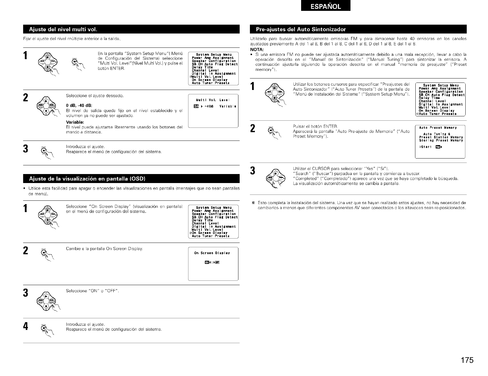
Fijar el ajuste del nivel mOltiple anterior a Jasalida
En la pantaEla "System Setup Me_u"( MenQ
de Configuraci6_ de1 Sistema) seleccione
"Multi Vul Level"(Nivel Multi Vul) y prise el
boron ENTER
ISystem Setup Menu
Power Amp Assignment
Speaker Configuration
SB CH Auto Flee Detect
Delay Time
Channel Level
OIiItml In As$11nment
a_,tulti Vol, Level
On Screen Dlapley
Auto Tuner Preeete
2SeEeccione elaiuste deseado
0 dB, -40 dB:
El nivel de safida queda fjo en el nivel establecido y el
volumen ya no puede ser ajustado
Variable:
El rfivel puede ajustarse libremente usa_do los botones del
ma_do a dista_cia
Multi VOI* Level
[] _ -401_ Variable
3htroduzca el ajuste
Reaparece el menO de configuraci6n de] sistema
•Utilice esta fadfidad para apagar o encender las visuafizaciones en pantalla (mensajes que no sean pantallas
de menQ)
2
SeecconexOnScreenDsp Y''visu iz c6ne pan aa'/...,.m,. u .nut
en el menQ de configuraci6n del sistema Power _p Aseignment
Speaker Configuration
SB CH Auto Flee Detect
Oelay Time
Channel Level
Ol_ltll In As$11nment
Multi Vol, Level
DOn Screen Dlspley
Auto Tuner Preeete
Cambie a la pa_tafla On Screen Display On Screen Display
Utilizarlo para buscar automaticamente emlsoras FM y para almacenar hasta 40 emisoras en los canales
aiustados previamente A del 1 al 8, B del 1 al 8, C del I al 8, D de11 al 8, E del I al 8
NOTA:
•Si una emisora FM no puede ser aiustada automaticamente debido a una rnala recepci0n, Ilevar a cabo la
operaci0n descrita en el "Manual de Sir_to_izaci6n" ("Manual Tdning') pare sintonizar la emisora A
co_ltinuaci6_l ajustada siguiendo la operaci6n descrita e_l el manual "melnoria de preajuste" ("Preset
memory")
Udlizar los botones cursores para especificar "Preaiustes del
Auto Sintonizador" ("Auto Tdner Presets") de la pa_tafla de
"MenQ de Instalaci6n del Sistema" ("System Setup Menu")
Syetem Setup Menu t
Power Amp Assl|nment
Speaker Configuration
SB CH Auto FI_E Detect
Oeley Time
Channel Level
DIEItal In AsslEnment
Multi VoL Level
On Screen Di$plly
_Auto Tuner Presets
2Pulsar el boton ENTER
Aparecera la pantalla "Auto Pre-ajuste de Memoria" ("Auto
Preset Memory")
Auto Preeet Memory
Aute Tunfn= &
Preset Station Memory
$torTn_ Preset Memory
uStart []_
Udlizar el CURSOR para seleccionar "Yes" ("Si")
"Search" ("Buscar") parpadea en la pantalla y comienza a buscar
"Completed" ("Completado") aparece una vez que se haya completado la bOsqueda
La visualizaci6n automaticamente se cambia a pantalla
Esto complete la instalaciOn del s sterna Urea vez que se hayan realizado estos ajustes, no hay necesidad de
carrlbiarlos a menos que diferentes componentes AM seen conectados o los altavoces searl re-posicionados
Seleccione "ON" o "OFF"
htroduzca el ajuste
Reaparece el menO de configuraci6n de] sistema
175
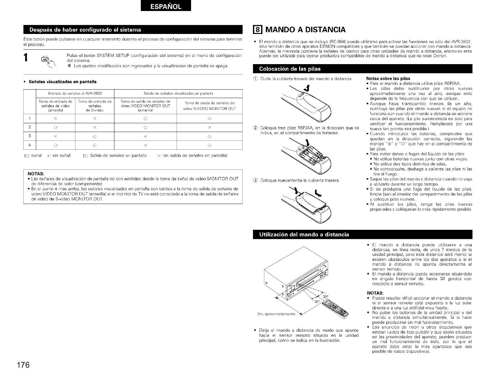
Este bot6n puede pulsarse en cualquier momento durante el proceso de configuraci6n del sistema para termlnar
el proceso
1Pulse el boton SYSTEM SETUP (configuracion de1 sistema) en eEmenO de configuracion
del sistema
Los ajustes modificados son ingresados y la visualizaciOn de pantaEla se apaga
•Seflales visualizadas en pantalla
En lada de senales a_AVR_802 Salida de senales v st,alizadasen parltal a
Toma de entrada de To¥_ade entradade Toma de sal[dade senaes de Tomade salida de senales de
senales de video sef'ales video VDEO MONITOR QU[
(area ilia} de S video (ar,/ar Ila) video SWIDEQMONITOR QU[
1 x x ( )
2 0 x ( x
3x(x0
40 () x 0
(o: senaE ×: s_r_serial) ((3: SaEidade senales en pantalla x: sin salida de senales en pantalla)
NOTAS:
• Las senales de visualizaciOn de pantalla no son emit das desde la toma de serial de video MONITOR OUT
de diferencia de color {componente)
• En el punto 4 mas arriba, las senales visualizadas en pantaNa son salidas a la toma de salida de senales de
video VIDEO MONITOR OUT {amarilla) si el monitor de TV no esta conectado a la toma de salida de senales
de video de S-video MONITOR OUT
[] MANDO A DISTANCIA
• El mando a distancia que se incluye (RC-884) puede utiEzarse para activar las funciones no s61o del AVR-3802,
sino tambien de otros aparatos DENON compatibles y que tambien se puedan accionar con mando a distancia
Ademas, la memoria contiene la senales de control para otras unidades de mando a distancia, entonces esta
puede set utilizada para operar productos compatibles de mando a distancia que no sean Denon
'il Quite la cubierta trasera del mando a distancia
"/2 Coloque tres pilas R6P/AA, en la direcciOn que se
indica, en el compartimento de batebas
@ Coloque nuevamente la cubierta trasera
%
Notas sobre las pilas
• Para el mando a distancia utilice pilas R6P/AA
• Las pilas debe sustituirse por otras nuevas
aproximadamente una vez al al_o, 8tJnque esto
depende de la frecuencia con que se utilicen
• Aul_que haya transctirrido menos de tin arlo,
sustituya las pilas pot otras nuevas sl el equipo no
funciona a0n cuando el mando a distancia se accione
cerca de1 aparato {La pila suministrada es solo para
vedficar el funcionamiento Remplacela pot una
nueva tan pronto sea posible )
• Cuando introduzca las batebas, compruebe que
quedan en la direcciOn correcta, siguiendo las
marcas "0" y "0" que hay en el compartimento de
las pilas
• Para evitar danos o fugas del I_quido de las pilas:
• No utilice batedas nuevas junto con otras wejas
• No utiEce dos tipos distintos de pilas
• No corlocircuite, deshaga o caliente las pilas ni las
tire al fuego
• Saque las pilas del mando a distancia cuando no vaya
a utiEzado durante un largo tiempo
• Si se produjera una fuga del liquido de las pilas,
limpie bien eEinterior del compartimento de las pilas
y coloque pilas nuevas
• AI sustituir las pilas, tenga las pilas nuevas
preparadas y col6quelas Io mas rapidamente posible
• Dirija el mando a distancia de modo que apunte
hacia el sensor remoto situado en la unidad
principal, como se indica en la ilustraciOn
• El mando a distancia puede utilizarse a una
d stancia, en linea recta, de unos 7 metros de la
unidad principal, pero esta distancia sera menor sl
existen obstaculos entre los dos aparatos o si el
mando a distancia no apunta directamente al
sensor remoto
• El mando a distancia ptiede accionarse situandolo
en angulo horizontal de hasta 30 grados con
respecto a sensor remoto
NOTAS:
• Puede resultar dificil accionar el mando a distancia
si el sensor remoto esta expuesto a la luz solar
d recta o a una luz aruficial muy fuer_e
• No pulse los botones de la unidad principal y del
mando a distancia simultaneamente Si Io hace
puede producirse an mal ftincionamiento
• Los anunclos de neon u otros dispositivos que
emitan ruidos de tipo puBatil y que esten situados
en las proximidades del aparato, pueden producir
un real funcionamiento de este, pot Io que el
aparato debe estar Io mas apartados que sea
posible de estos dispositivos
176
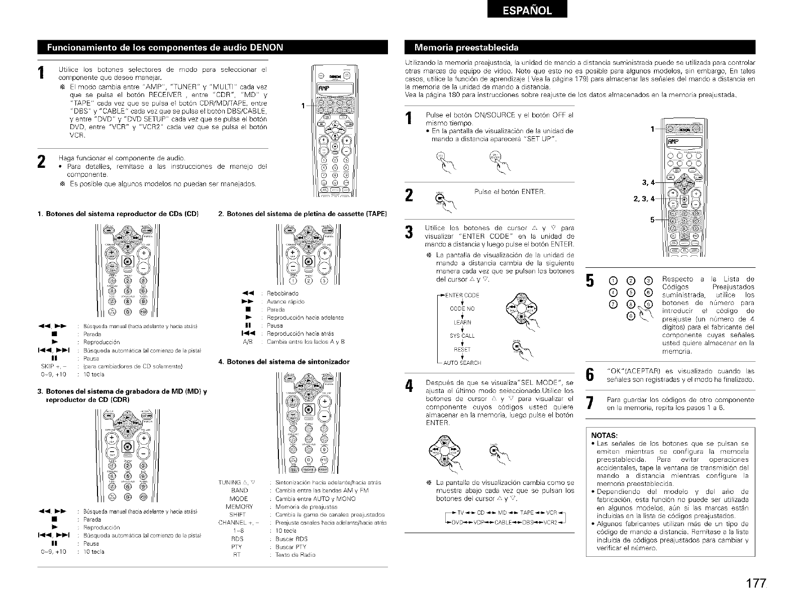
2
Utlice los botones seEectores de modo para seEeccionar el
componente que desee manejar
El modo cambia entre "AMP", "TUNER" y "MULTI" cada vez
que se pulsa el boron RECEIVER ,entre "CDR", "MD" y
"TAPE" cada vez que se pulsa el boron CDR/MD/TAPE, entre
"DBS" y "CABLE" cada vez que se pulsa el boton DBS/CABLE,
¥ entre "DVD" y "DVD SETUP" cada vez que se pulsa el botdn
DVD, entre "VCR" ¥ "VCR2" cada vez que se pulsa el boron
VCR
Haga funcionar el componente de audio
• Para detaEles, remftase alas instrucciones de manejo del
componeRte
Es posible que aEgunos modelos no puedan set manejados
1. Botones del sistema reproductor de CDs (CD) 2. Botones del sistema de ptetina de cassette (TAPE)
®@@ @
@ @ @
@@0
44 _'1_ : B squeda manual fhacia adelante y hacia arras)
• : Parada
II_ : Reproducci6n
I_1, !1_1_1 : B_isqueda _utom_tic_ lal comienzo de I_ pist_}
II : Pausa
SKIP +, : (para canlb adores de CD so]ameTlte)
0 9,+10 : 10 tecla
3, Botones del sistema de grabadora de MD (MD) y
reproductor de CD (CDR)
®@@ @
® ® ®
®®®
4141 _'1_ : B squeda manual fhacia adelante y hacia arras)
• : Parada
II_ : Reproducci6n
I_1, I_1_1 : B_isqueda _utom_tic_ I_l comienzo de I_ pist_}
II : Pausa
0 9,+10 : 10 tecla
_1_1 Rebob nado
_-1_ Avance r_pdo
• Parada
I_ Reproducci6n hac[a adelante
II Pausa
14141 Reproducci6n hacia arras
A/B Cambia entre los lados A y B
4, Botones del sistema de sintonizador
,@ @
® @ @
© @ ®
TUNING :_,
BAND
MODE
MEMORY
SHIFT
CHANNEL+,
1_8
RDS
PTY
RT
SirltoTl[zaci@l hac[a adelante/hacia atras
Camb_a eTltre las bandas AM y FM
Camb_a eTltre AUTO y MONO
Merr/oria (1¢ p/_ajustes
Carflb_a la gaRla de callales preaiustados
Preaiu st8 canal®s hacia adelante/hacia atlas
I 0 tecta
Buscar RDS
Buscar PTY
Texto de Rado
Utilizando la memoria prea}ustada, la unidad de mando a distancia suministrada puede se utilizada para controlar
otras marcas de equipo de v_deo Note que esto no es pos ble para algunos modelos, sin embargo, En tales
caSOSr utilice la funci6n de aprendizaje ( V_a la pagina 179} para almacenar las seriales del mando a distancia en
la memoria de la unidad de mando a distancia
Vea la pagina 180 para instrucciones sobre reajuste de los datos almacenados en la memoda preajustada
Pulse el bot6n ON/SOURCE y el bot6n OFF al
mismo tiempo
•En la pantalla de visualizacion de la unidad de
mando a distancia aparecera "SET UP"
1
Pulse el boron ENTER
3
4
Utlice los botones de cursor y para
visualizar "ENTER CODE" en la unidad de
mando a distancia y luego pulse el botOn ENTER
La pantafla de visualizacion de la unidad de
mando a distancia cambia de la siguiente
manera cada vez que se pulsan los botones
del cursor _ y,
_ENTERCODE
CODENO
i
LEARN
SYSCALL
i
RESET
AUTOSEARCH
Despues de que se visualiza"SEL MODE", se
ajusta el Okimo modo seleccionado Utilice los
botones de cursor , y para visualizar el
componente cuyos codigos usted qulere
almacenar en la memona, luego pulse el bot6_
ENTER
La pantalla de visualizaciOn cambia como se
muestra abajo cada vez que se puisan los
botones del cursor, y
3,4
2,3,4
5
5(_ (_ _) Respecto a la Lista de
C6digos Preajustados
(_ (_ (_ suministradar utilice los
(_ @_ botolles de nOrnero para
introducir el codigo de
preajuste {un nQmero de 4
digitos) para el fabricante del
componente cuyas senales
usted quiere almacenar eR la
memoria
"OK"(ACEPTAR) es visualizado cuando las
senales son registradas y el modo ha finalizado
Para guardar los cOdigos de otto componente
en la memona, repita los pasos 1 a 6
NOTAS:
• Las senales de los botones que se pulsan se
emiten mientras se configura la memoRa
preestablecida Para evitar operacio_es
accidentales, tape la ventana de transmisi6n del
mando a distancia mientras configure la
memoria preestablecida
• Dependiendo del modelo y del ano de
fabdcaci6n, esta funci6n no puede set utilizada
e_ a[gunos modelos, aBn si las marcas esta_
incluidas en la lista de c6digos preajustados
• Algul_os fabricantes utilizan mas de un tipo de
c6digo de mando a distancia Remitase a la lista
incluida de cod gos preajustados para cambiar y
verificar el nQmero
177
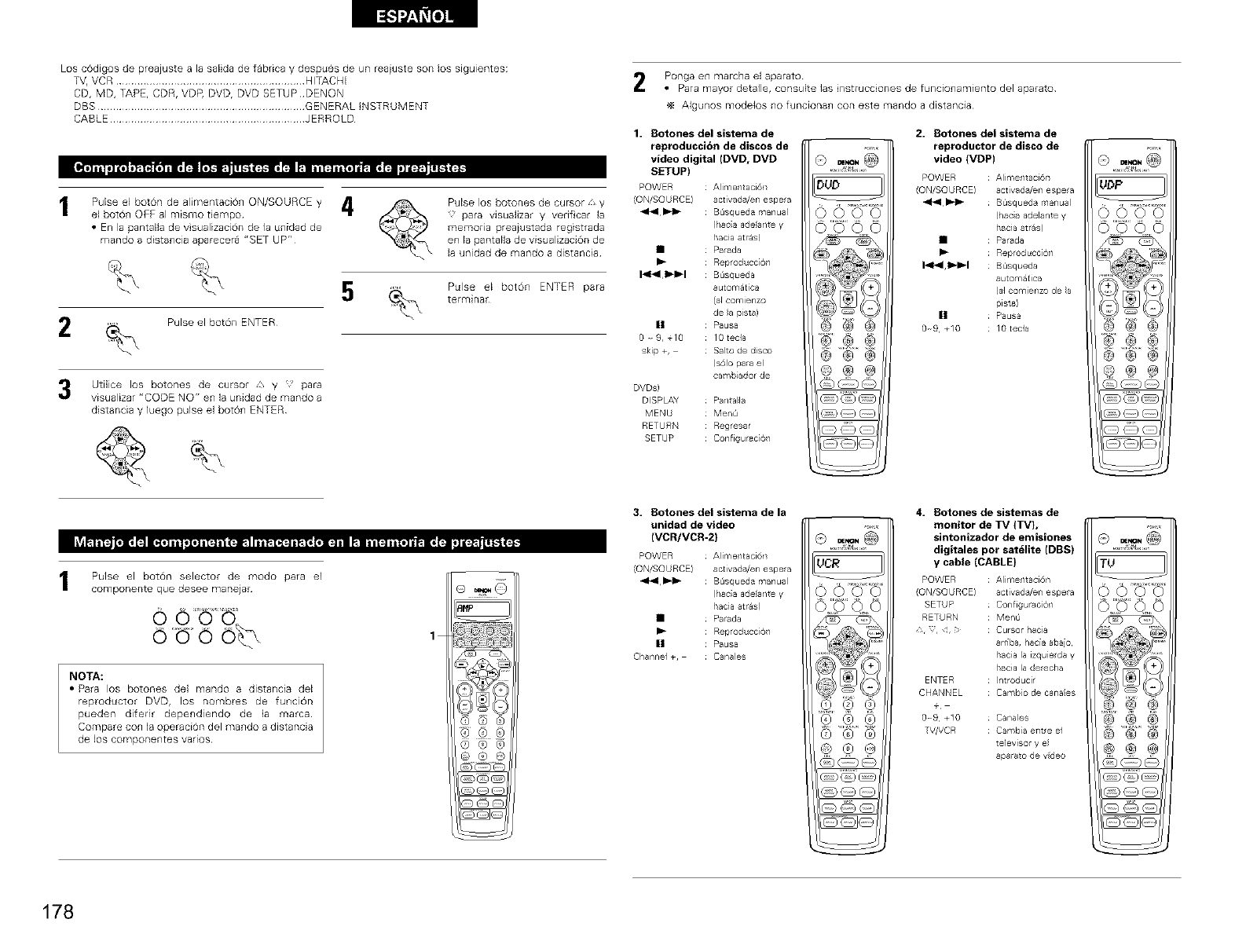
Los codigos de preajuste a la salida de fabrica y despues de un reaiuste son los siguientes:
TV, VCR .............................................................. HITACHI
CD, MD, TAPE, CDR, VDP, DVD, DVD SETUP DENON
DBS .................................................................... GENERAL INSTRUMENT
CABLE ................................................................ JERROLD
Pulse el bot6n de aNmentaci6n ON/SOURCE y
el boton OFF al m[smo tiempo
• En la pantalla de visualizaci6n de la unidad de
mando a distancia aparecera "SET UP"
Pulse el boton ENTER
i_ Pulse los botones de cursor y
para visualizar y verifcar la
memona prea}ustada registrada
en la pantalla de visualizaci6n de
la unidad de mando a distancia
Pulse el boton ENTER para
terminar
Uti]ice los botones de cursor > y * para
visualizar "CODE NO" en la unidad de mando a
distancia y luego pulse el boron ENTER
Ponga en marcha el aparato
•Para mayor detalle, consulte las nstrucciones de funcionamiento del aparato
AIgunos modelos no funcionan con este mando a distancia
1. Sotones del sistema de
reproduccion de discos de
video digital (DVD, DVD
SETUP}
POWER Alinlentaci@l
(ON/SO RCE) activada/en espea
41411_1_ BOsqueda manual
(/aoa ade al/te y
hacia atr_sl
• Paada
I_ Reproduce 6n
I-_1, I_1_1 BL_squeda
automatica
(al comienzo
de a pista)
n Pausa
0 9, TIO 10 tecla
skip +, Sato de disco
(s61o para el
ca ¥_biador de
DVDs)
DISPLAY Pa/ta la
MENU MenL_
RETURN Regresar
SETUP Configurac 6/
bud
0©'_'5'
©'_'00
®®®
2. Sotones del sistema de
reproductor de disco de
video (VDP)
POWER Alimentaci@l
(ON/SO RCE) activada/en espea
4141 _-I)- BL_squeda manual
(/aca adelante y
hacia atr_s)
• Parada
I_ Reproduce @/
I-_1, I_1_1 BL_squeda
automatica
(al comienzo de a
pista)
n Pausa
0-9 +10 I0 tecla
@@@
Pulse el boton selector de modo para el
componerlte que desee manejar
0 0
NOTA:
• Para los botones del mando a distancia del
reproductor DVD, los nombres de funci@_
pueden difedr dependiendo de la marca
Compare con la operacion del mando a distancia
de los componentes VarlOS
1
3. Sotones del sistema de la
unidad de video
(VCR/VCFI-2}
POWER Alirl/ent aci@l
(ON/SO RCE) activada/en espea
_1_11_1_ BOsqueda manual
(/aoa ade al/te y
hacia atr_sl
• Paada
I_ Reploducc 6 /
II Pausa
Channel +, Canales
UCR
OOOO
©'_'0 ©
© @ @
©®®
4. Sotones de sistemas de
monitor de TV (TV},
sintonizador de emisiones
digitales pot satelite (DBS)
y cable (CABLE}
POWER Aliment aci6r/
(ON/SO RCE) activada/en espera
SETUP Configurac 6n
RETURN MenL_
,, , Cursor hacia
arr[ba, hac[a abaio,
hacia la izquierda y
hacJa la derecha
ENTER Introducir
CHANNEL Cambo de cana es
Canales
TV/VCR Camb[a e_ltre el
televisor y el
aparato de video
@@@
@@@
178
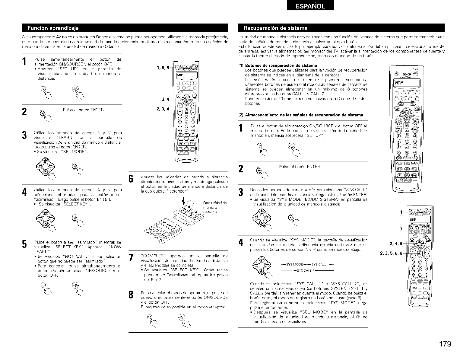
Si su componente AV no es un producto Denon o si este no puede set operado utilizando la memoria preaiustada,
este puede ser controlado con la unidad de mando a distancia mediante el almacenamiento de sus senabs de
mando a distancia en la unidad de mando a distancia
Pulse simultaneamente el bot6n de
alimentaci6n ON/SOURCE y el bot6n OPR
• Aparece "SET UP" en la pantalla de
visualizaciOn de la unidad de mando a
distancia
1,5,8
2Pulse el bot6n ENTER
3
3,4
2,3,4
Utilice los boto_les de cursor _ y para
visualizar "LEARN" en la pa_talla de
visualizaci6n de la unidad de mando a distancia,
luego pulse el boton ENTER
• Se visualiza "SEL MODE"
4
5
Utilice los boto_es de cursor _ y para
seleccionar el modo para el boton a ser
"asimilado", luego pulse el boton ENTER
• Se visualiza "SELECT KEY"
Pulse el boton a set "asimilado" mientras se
visualice "SELECT KEY" Aparece "NOW
LEARN"
• Se visualiza "NOT VALID" si se puba un
boton que no puede set "asimilado"
• Para cancelar, pulse sirnultaneamente el
boton de alimentacion ON/SOURCE y el
boton OFR
6Apunte las unidades de mando a distancia
directamente unas a otras y mantenga pulsado
el boton en la unidad de mando a distancia de
la que quiere " aprender"
__ l,Otra undad de
_:_ ando a
7r'COMPLET" aparece en la pantaHa de
visualizaci6n de la unidad de mando a distancia
y el aprendizaje se completa
• Se visualiza "SELECT KEY" Otras teclas
pueden ser "asimiladas 'r al repetir los pasos
del 5 al 7
8Para cancelar el modo de aprendizaje, pulse de
nuevo simultaneamente el botO_ ON/SOURCE
y el boton OFR
El registro no es posible en el modo receptor
La unidad de mando a distancia esta equipada con una funcion de Ilamada de sistema que permite transmitir una
serie de senales de mando a distancia al pulsar un simple boton
Esta funcion puede set utilizada pot ejemplo para activar la alimentacion del amplificadoh seleccionar la fuente
de entrada, activar la alimentaciOn del monitor del T_4 activar la alimentaciOn de los componentes de fuente y
aiustar la fuente al modo de reproducciOn, todo con el toque de un boton
(1) Botones de recuperacidn de sistema
Los botones que pueden utilizarse para la funcion de recuperaci6n
de sistema se indican en el diagrama de la derecha
Las seriales de Ilamada de sstema se pueden almacenar en
d ferentes botones de acuerdo al modo Las senales de Ilamada de
sistema se pueden almacenar en un maximo de 6 botones
d ferentes a los botones CALL 1 y CALL 2
Pueden ajustarse 29 operaciones sucesivas en cada uno de estos
botones
(2) Almacenamiento de las se_,ales de recuperacibn de sistema
Pulse el boton de alimentacion ON/SOURCE y el boton OFF al
mismo tiempo En la pantaila de visualizaci6n de la unidad de
mando a distancia aparecera "SET UP"
Pulse e] boron ENTER
3Utilice los botones de cursor "y para visualizar "SYS CALL"
en la unidad de mando a distancia y luego pulse el boton ENTER
• Se visualiza "SYS MODE"(MODO SISTEMA) en pantalla de
visualizaciOn de la unidad de mando a distancia
AHP
)OOC
® @ ®
@@@
1
Cuando se visualiza "SYS MODE", la pantalla de visualizaciOn
de la unidad de mando a distancia cambia cada vez que se
pulsar los botone8 de cursor V como se muestra abajo
7
3,4,5
2,3,5,6,8
Cuando se selecciona "SYS CALL 1" o "SYS CALL 2", 1as
senales son almacenadas en los botones SYSTEM CALL 1 y
CALL 2 (verde), sin tenet en cuenta el modo Cuando se pulsa el
botO_ enteh el modo de registro de boton se ajusta (paso 6)
Para registrar otros botones, seleccio_e "SYS MODE" luego
pulse el boton e_ter
• Despues se visualiza "SEL MODE" en la pantaila de
visualizaci6_ de la unidad de mando a dista_cia, el _ltimo
modo ajustado es visualizado
179
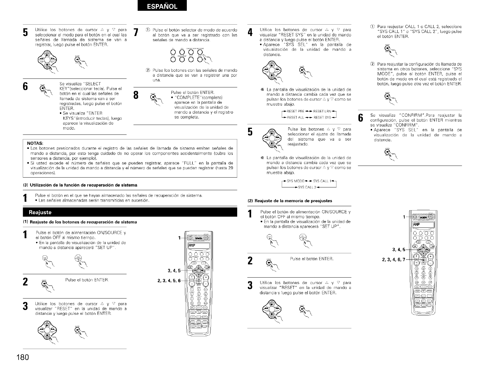
5
6
Utilice los botones de cursor _ y para
seleccionar el modo para el bot6n en el cual las
seriales de Ilamada de sistema se van a
registrar, luego pulse el bot6n ENTER
Se visualiza "SELECT
KEY"(seleccionar tecla) Pulse el
boton en el cual las senales de
Ilamada de sistema van a set
registradas, Iuego pulse el boton
ENTER
• Se visualiza "ENTER
KEYS"(introducir tedas), luego
aparece la visualizacion de
modo
T Pulse el boton selector de modo de acuerdo A
al boton que va a ser registrado con las
senales de mando a distancia
O 0
ouo ob
Pulse los botones con 1as seEiales de mando
a distancia que se van a regEstrar uri8 pot
una
8Pulse el boton ENTER
• "COMPLETE"(completo)
aparece en la pantalla de
visualizacion de la unidad de
mando a d stancia y el registro
se completa
NOTAS:
• Los botones presionados durante el regstro de las seriales de Ilamada de sistema emiten senales de
mando a distancia, pot esto tenga cuidado de no operar los componentes accidentalmente (cubra los
sensores a distancia, por e}emplo)
• Si usted excede el nQmero de senales que se pueden registrar, aparece "FULL" en la pantalla de
visualizacion de la unidad de mando a distancia y el nQmero de senales que se pueden registrar (hasta 29
operaciones)
(3} Utilizacion de la funci6n de recuperacion de sistema
Pulse el boton en el que se hayan almacenado las senales de recuperaci0n de sistema
• Las serlale8 almacenadas serar] tfansm]tidas erl sucesi6r]
(1} Rea|uste de los botones de recuperacion de sistema
Pulse el bot6n de alimentaci6n ON/SOURCE y
el boton OFF al m[smo tiempo
• En la pantalla de visualizaci6n de la unidad de
mando a distancia aparecera "SET UP"
1
2 Pulse el bot6n ENTER
3,4,5
2,3,4,5,6
Utilice los botones de cursor ::, y ;' para
visualizar "RESET" en la unidad de mando a
distancia y luego pulse el bot6n ENTER¸
Utilice los botones de cursor ,* y 'para
visualizar "RESET SYS" en la unidad de mando
a distancia y luego pulse el boton ENTER
• Aparece "SYS SEL" en la pantalla de
visualizaciOn de la unidad de mando a
distancia
La pantalla de visualizacion de la unidad de
mando a distancia cambia cada vez que se
pulsan los botone8 de cursor _ y como se
muestra aba}o
5Pulse los botones , y _ para
seleccionar el ajuste de Ilamada
del sstema que va a set
reajustado
La pantalia de visualizaci0n de la unidad de
mando a distancia cambia cada vez que se
pulsan los botones de cursor _ y como se
muestra aba}o
(2) Reajuste de la memoria de preajustes
Pulse el bot6n de alimentacion ON/SOURCE y
el boton OFF al mismo tiempo
• En la pantalla de visualizaci6n de la unidad de
mando a distancia aparecera "SET UP"
Pulse e] boron ENTER
Utilice los botones de cursor y para
visualizar "RESET" en la unidad de mando a
distancia y luego pulse el boron ENTER
f-,
1,= Para reaiustar CALL 1 o CALL 2rseleccione
"SYS CALL 1" o "SYS CALL 2", luego pulse
el bot6n ENTER
"/2 Para reajustar la conf guraciOn de Ilamada de
sistema en otros botones, seleccione "SYS
MODE", pulse el boton ENTER, pulse el
boron de modo en el cual esta registrado el
boron, ]uego paise otra vez el boton ENTER
6Se visualiza "CONFIRM"Para reajustar la
configuracionr pulse el botOn ENTER mientras
se visualiza "CONFIRM"
• Aparece "SYS SEL" en la pantalla de
visualzaciOn de la unidad de mando a
distancia
1
3,4,5
2,3,4,6,7
180
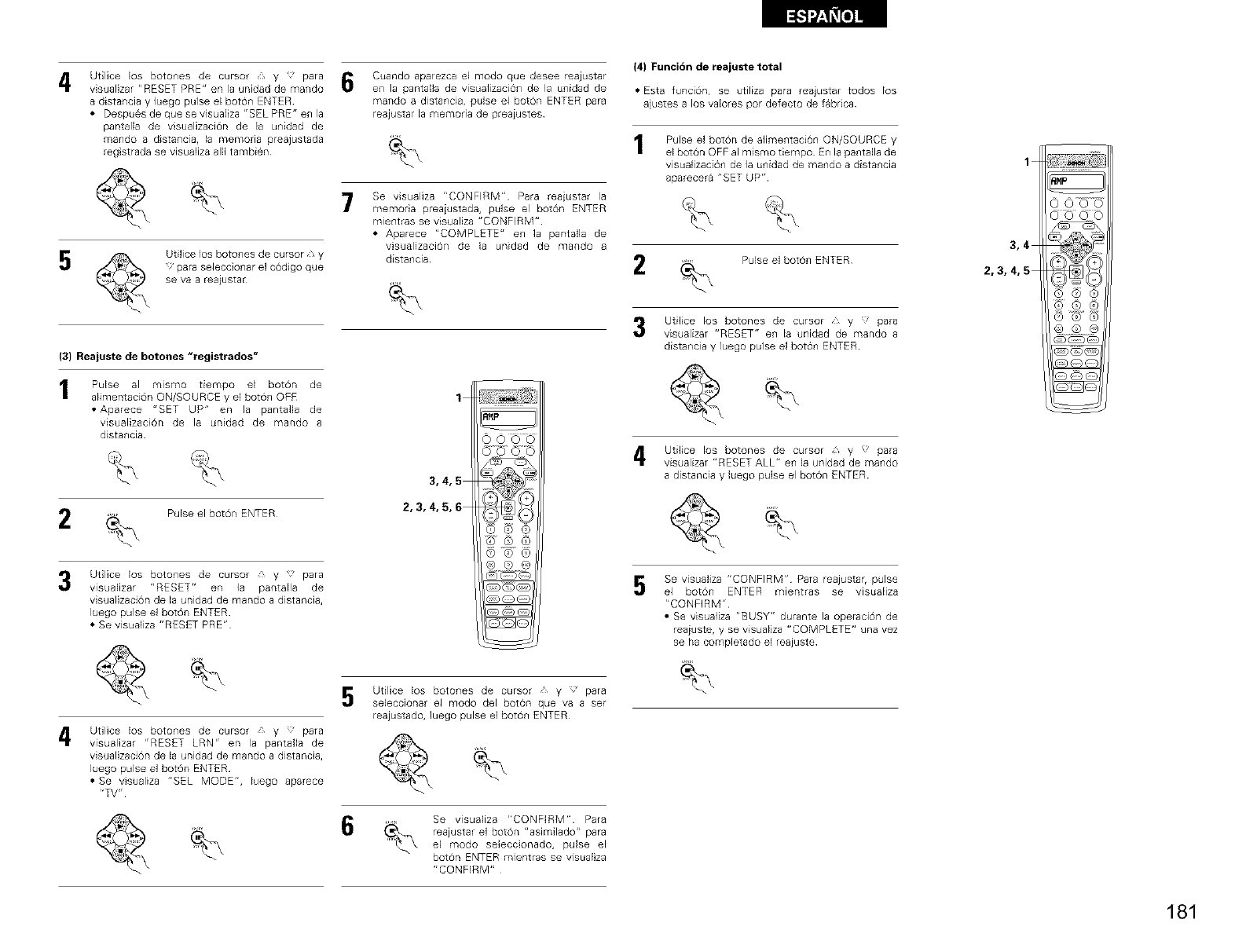
4Utilice los botches de cursor _, y para
visualizar "RESET PRE" en la unidad de mando
a distancia y luego pulse el botch ENTER
• Despues de que se visuaEiza "EEL PRE" en la
pantalla de visualizaciOn de la unidad de
mando a distancia, la memona prea]ustada
reg strada se visualiza alli tambien
5Utilice los botones de cursor y
para seleccionar el c6digo que
se V8 8reEiustEr
(3} Reajuste de botones "registrados"
Pulse al mismo tiempo el bot0n de
alimentaci6n ON/SOURCE y el bot0n OFF
• Aparece "SET UP" en la pantalla de
visualizaci6n de la unidad de mando a
distancia
6Cuando aparezca el modo que desee reajustar
en la pantalla de visualizaciOn de la unidad de
mando a distancia, pulse el bOtCh ENTER para
reajustar la memoria de preaiustes
7Se visualiza "CONFIRM" Para reaiustar la
memoria preaiustada, pulse el boron ENTER
mientras se visualiza "CONFIRM"
• Aparece "COMPLETE" en la pantafla de
visualizaciOn de la unidad de mando a
distancia
(4) Funcion de reajuste total
• Esta funci@], se utiliza para reajustar todos los
ajustes a los valores por defecto de fabrica
Pulse el bOtCh de alimentaciOn ON/SOURCE y
el boron OFF al mismo tiempo En la pantalla de
visuafizacion de la unidad de mando a distancia
aparecera "SET UP"
Pulse el botch ENTER
1
3,4
2,3,4,5
Pulse el botch ENTER
3Utilice los botches de cursor £ y para
visualizar "RESET" en la pantalla de
visualizacion de la unidad de mando a distancia,
luego pulse el botOn ENTER
• Se visualiza "RESET PRE"
1
3,4,5
2,3,4,5,6
Utilice los botones de cursor y para
visualizar "RESET" en la unidad de mando a
distancia y luego pulse el botch ENTER
4 Utilice los botones de cursor _f, y ' para
visualizar "RESET ALL" en ]a unidad de mando
a distancia y luego pulse el boton ENTER¸
5Se visuafiza "CONFIRM" Para reajustar, pulse
el botch ENTER mientras se visualiza
"CONFIRM"
• Se visualiza "BUSY" durante la operacion de
reaiuste, y se visualiza "COMPLETE" una vez
se ha completado el reaiuste
4Utilice los botches de cursor £ y para
visualizar "RESET LRN" en la pantalla de
visualizaciOn de la unidad de mando a distancia,
luego pulse el botch ENTER
• Se visualiza "SEL MODE", luego aparece
"TV"
Utilice los botches de cursor y para
seleccionar el modo del boton que va a set
reajustado, luego pulse el bot0n ENTER¸
Se visualiza "CONFIRM" Para
reajustar el botOn "asimilado" para
el modo selecconado, pulse el
botch ENTER mientras se visualiza
"CONFIRM"
181
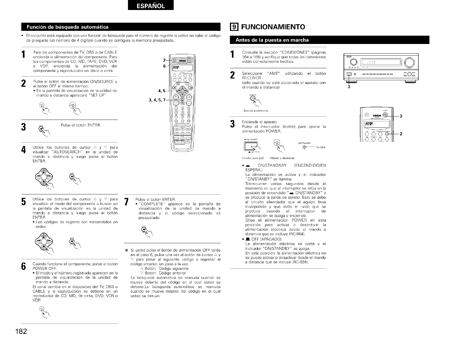
• El coniunto esta equipado con una funci6n de bOsqueda para el n0mero de reg stro si usted no sabe el c6digo
de preajuste (un nOmero de 4 digitos} cuando se configura la memoria preajustada
Para los componentes de TV, DBS o de CABLE
encienda 18alimentacion del componente Para
los componentes de CD, MD, TAPE, DVD, VCR
y VDP, encienda la alimentaciOn del
compone_te y reproducci6n un disco o cinta
2
6
2Pulse el bo16n de alimentaci0_ ON/SOURCE y
el bot0n OFF al mismo tiempo
• En la pantalla de visualizaci6n de ]a unidad de
mando a distancia aparecera "SET UP"
4,5
3,4,5,7
Pulse el bot6n ENTER
4Utilice los botones de cursor /, y para
visualizar "AUTOSEARCH" en la unidad de
mando a distancia y luego pulse el bot6n
ENTER
5Utilice los botones de cursor × y para
visualizar el modo del componente a buscar en
la pantaEla de visuaEizacion en la unidad de
mando a distancia y luego pulse el boron
ENTER
• Los codigos de reg stro son transmitidos en
orden
7Pulse el boton ENTER
• "COMPLETE" aparece en la par_talla de
visualizaciOn de la unidad de mando a
distancia y el codigo seleccionado es
preaiustado
6Cuando funcione el componente, pulse el boton
POWER OER
• El modo y el nt_mero registrado aparecen en la
pantalla de visuafizaci6n de la unidad de
mando a d stancia
El canal cambia en el dispositivo del %/, DBS o
CABLE y la reproducci6n se detiene en un
reproductor de CD, MD, de cinta, DVD, VCR o
VDR
Si usted pulsa el bot6_ de alimentaci6n OFF tarde
en el paso 6, pulse una vez el boton de cursor _ y
'para pasar al siguiente c6digo o regresar al
c6digo anteHoh un paso a la vez
y, Boton: C6digo siguiente
Boton: C6digo anterior
La bOsqueda automatica se reanuda cuando se
mueve delante del c6dgo en el cual usted se
detuvoLa bOsqueda automatica se reanuda
cuando se mueve delante del c6digo en el cuai
usted se detuvo
[] FUNCIONAMIENTO
1 C°nsultela secciOn"CONEXlONES"(paghas [_,0 l[ I} O
164 a 168} y verif que que todas 1as conexiones
estan correctamente hechas . . : : :
oooo . .
Selecc'one "AMP" utilizB,ido el bot6r, r_ @ _=_O_=_
RECEIVER
(s01o cuando se este accionado el aparato con
el mando a distancia) 3
,%
frvl_ndo _ distanc_a)
Encienda el aparato
Pulse el interruptor (bot6n) para operar la
alimentacion POWER
!Unid_dpdr_clpa_l (M_ndo_distanc_a)
• .i ON/STANDABY (ENCENDIDO/EN
ESPERA )
La alimentaci6n se activa y el indicador
"ON/STANBY" se ilumina
T_anscurren varlos segundos desde el
momento en que el interruptor se sitOa en la
posicion de encendido "_ ON/STANDBY" y
se produce la salida de sonido Esto se debe
al circuito silenciador que el equipo Ileva
incorporado y que evita el ruido que se
produce cuando el interruptor de
alimentaciOn se apaga o enciende
Sit0e el alimentaciOn POWER en esta
poslciOn para activar o desactivar la
alimentaci0n electdca desde el mando a
distancia que se nduye (RC-884)
•III OFF (APAGADO)
La alimentaciOn electrca se corta y el
indicador "ON/STANDBY" se apaga
En esta posicion, la alimentacion electdca no
se puede activar o desactivar desde el mando
a distancia que se incluye {RC_884)
182
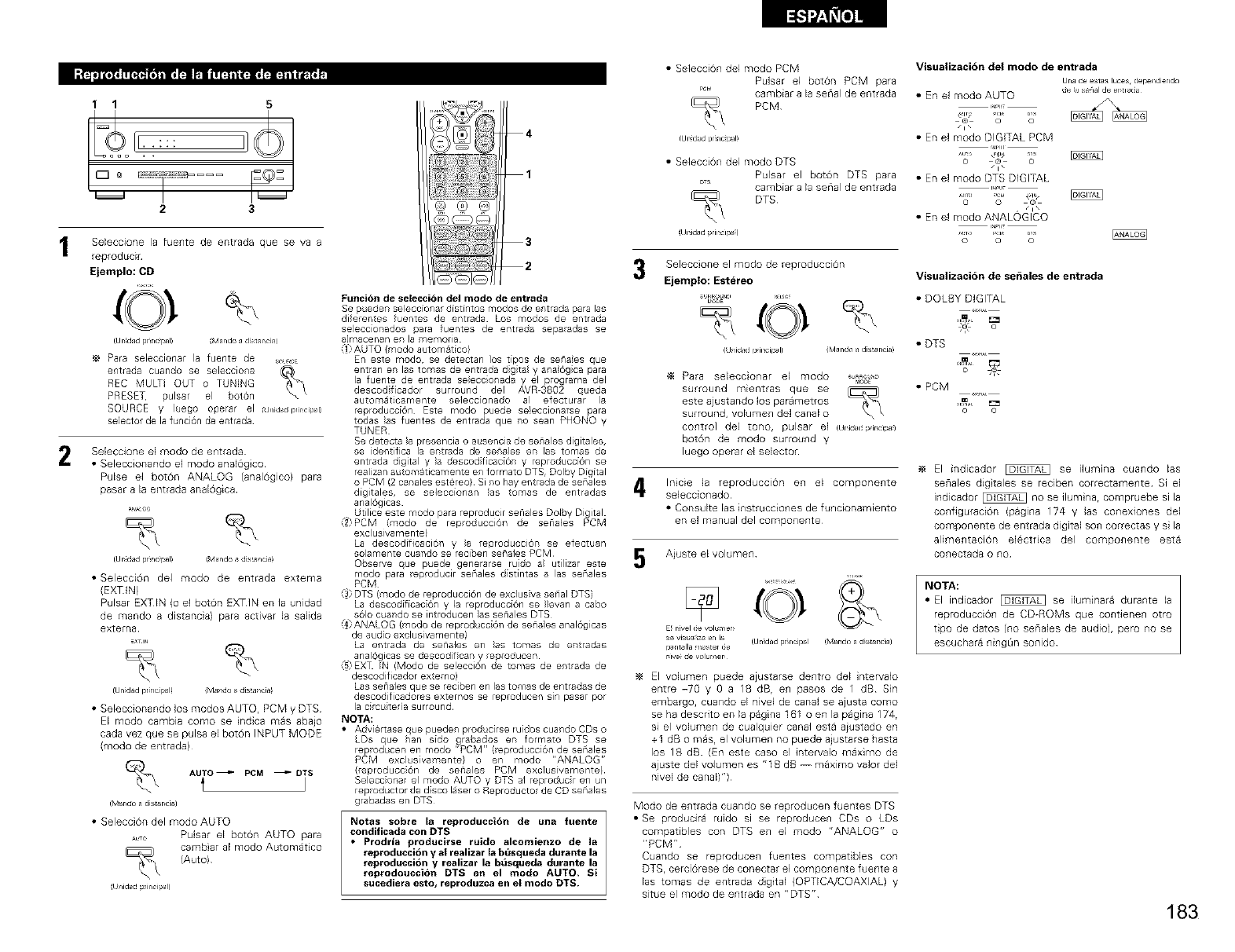
1 1 5
23
Seleccione la fuente de entrada que se va a
reprodudr
Ejemplo: CD
2
%
Ur idad pr_nc_l_ (Mando a d_st al_ci_
Para selecciona la fuente de SO,_CE
entrada cuando se selecciona
REC MULTI OUT o TUNING
PRESET, pulsar el botOn
SOURCE y luego operar el J/id_dprincipal)
selector de la funci6n de entrada
Seleccione el modo de entrada
•Seleccionando el modo anal6g co
Pulse el botOn ANALOG (analOgico) para
pasar a la entrada analOgEca
(Ur_kSadpr_ndpal) {Mando adis[ancia)
• SelecciOn del modo de entrada extema
(EXTIN)
Pulsar EXTIN (o el botOn EXTIN en la unidad
de mando a distancia) para activar la saWa
externa
_x =r_
{Urfidad rx_ncil_l! iMando a_dis_ancia!
• Seleccionando los modos AUTO, PCM y DTS
El modo cambia como se ndica mas abaio
cada vez que se pulsa el botOn INPUT MODE
(modo de entrada)
AUTO _PCM _ DTS
IM_,r do i distar cla)
• SelecciOn del modo AUTO
ATO Pulsar el boton AUTO para
cambiar al modo Automatico
(Auto)
(Uni@d pdncipal)
4
1
@@@
3
2
Funcibn de selecci in del mode de entrada
Se puedes seleccionar distintos modos de entrada para las
diferenes fuentes de entrada Los modos de entrada
seleccionados _ara fuentes de entrada sepaadas se
a]rnacenan en la memoria
:{i) AUTO (modo autom_tico}
En este modo, se detectan los tipos de seraes que
entran enlastomasdeentradadgta yara6gca para
la fuente de entrada seleccionada y el programa del
descodificador su round del AVR 3802 q/Jeda
automaticamente selecconado al efecturar la
reproducci6n Este modo puede se!eccionarse para
todas }as fuentes de entrada que ro sean PHONO y
TUNER
Se detecta la presencla o ausencia de senales digitales,
se identifica la entrada de seraes en las tomas de
entrada digital y }a descodficaci6n y reproducci6n se
realizan a tomaticamente en formato DTS, Dolby Digital
o PCM (2 canales estereo} Si ro hay entrada de senales
digitales, se seleccionan }as tomas de entradas
anal6glcas
Utilice este modo para reproducir sehales Dolby Digital
:2 PCM (modo de repoducci6n de senales PCM
exclusivamente}
La descodificaci6n y }a reproducci6r se efectuan
solamente c4Jandose reciben senales PCM
Observe que puede generarse ruido a utilizar este
modo para eproducir senales distintas a las senales
PCM
:3) DTS (modo de reproducci6n de exclus va senal DTS)
La descodificac 6n y la reproducci6n se }}evan a cabo
s61o cando se introducen }as sehales DTS
:_ ANALOG (modo de reprod cci6n de sera es anal6glcas
de audo exclusivamente)
La entrada de sehales en }as tomas de e tradas
anal6gicas se descod fican y eproducen
:5 EXT N Modo de seecc6n de tomas de entrada de
descodificador externo)
Lassenalesq eserecibenenlastomasdeentradasde
descodificadores externos se eproducen sin pasar por
lacirc terasurround
NOTA:
•Adviertaseq epuede prod cilseruidoscuardoCDso
LDs que ban sido grabados en formato DTS se
repod cenen modo'PCM'r(eprod cci6ndesenales
PCM excl sivamente} o en modo "ANALOG"
(reproducc6n de senales PCM exclusivamente)
Seleccional el modo AUTO y DTS al reproduc en un
repod ctordedscolaseroReproductordeCDsenales
grabadas en DTS
Notas sobre la reproducci6n de una fuente
condificada con DTS
•Prodria producirse ruido alcomienzo de la
reproduccion y at realizar la bt_squeda dura_te la
reproduccibn y realizar la b_squeda dura_te la
reprodouccibn DTS en el modo AUTO. Si
sucediera esto, reproduzca en et modo DTS.
3
• Selecci6n del modo PCM Visualizaci6n del modo de entrada
Pulsar el bot6n PCM para Una de esias lutes dependiendo
PC_,_ cambiar a la serial de entrada • Erl el modo AUTO de _asepal de er_tlaci_J
PCM '......
_11_© o I_
/i \
ur_idadprinci_l_ • En el modo DIGITAL PCM
• Selecci6n del modo DTS o eo
_1 _
Pulsar el bot6n DTS para • En el modo DTS DIGITAL
_TS cambiar a la serial de entrada
DTS o o o
/i \
• En el modo ANALOGICO
Seleccione el modo de reproducciOn
Ejemplo: Estereo
(/Jnid_d principal} irVla ndo a dista ncia!
_4 Para selecconar el modo o_-,
surrourld mientras que se
este ajustando los parametros
surround, volumen del canal o
control del tono, pulsar el (Ulqdadpircipa)
botOn de modo surround y
luego operar el selector
Incie la reproducci0n en el componente
seleccionado
•Consulte las instrucciones de funciorlalniento
en el manual del componente
Aiuste el volumen
E_r_iveldevulumer_
se visua_iza enia (Un_dad prLncipal
pantallamasterde
r_ive_de volumen
!blar_doad_st_r_cla)
El volumen puede ajustarse dentro del intervalo
entre -70 y 0 a 18 dB, en pasos de 1 dB Sin
embargo, cuando el nivel de canal se ajusta como
se ha descrito en la pagina 161 o en la pagina 174,
si el volumen de cualquier canal esta aiustado en
+I dB o mas, el volumen no puede aiustarse hasta
los 18 dB (En este caso el intervalo maximo de
ajuste del volumen es "18 dB -- maximo valor del
nivel de canal)")
Modo de entrada cuando se reproducen fuentes DTS
• Se producira ruido sl se reproducen CDs o LDs
compatibles con DTS en el modo "ANALOG" o
"PCM"
Cuando se reproducen fuentes compatibles con
UTS, cerciOrese de conectar el componente fuente a
las tomas de entrada digital (OPTICA/COAXIAL) y
situe el modo de entrada en "DTS"
Visualizaci6n de sefiales de entrada
• DOLBY DIGITAL
• DTS
• PCM
El indicador _ se ilumina cuando las
senales digtales se reciben correctamente Si el
indicador _ no se ilumina, compruebe si la
configuraci6n (pagina 174 y las conexiones del
componente de entrada digital son correctas y si la
alimentacion el6ctrica del componente esta
conectada o no
NOTA:
• El indicador _ se iluminara durante la
reproducd6n de CD-ROMs que contienen otro
tipo de datos (no senales de audio), pero no se
escuchara ningL_n sonido
183
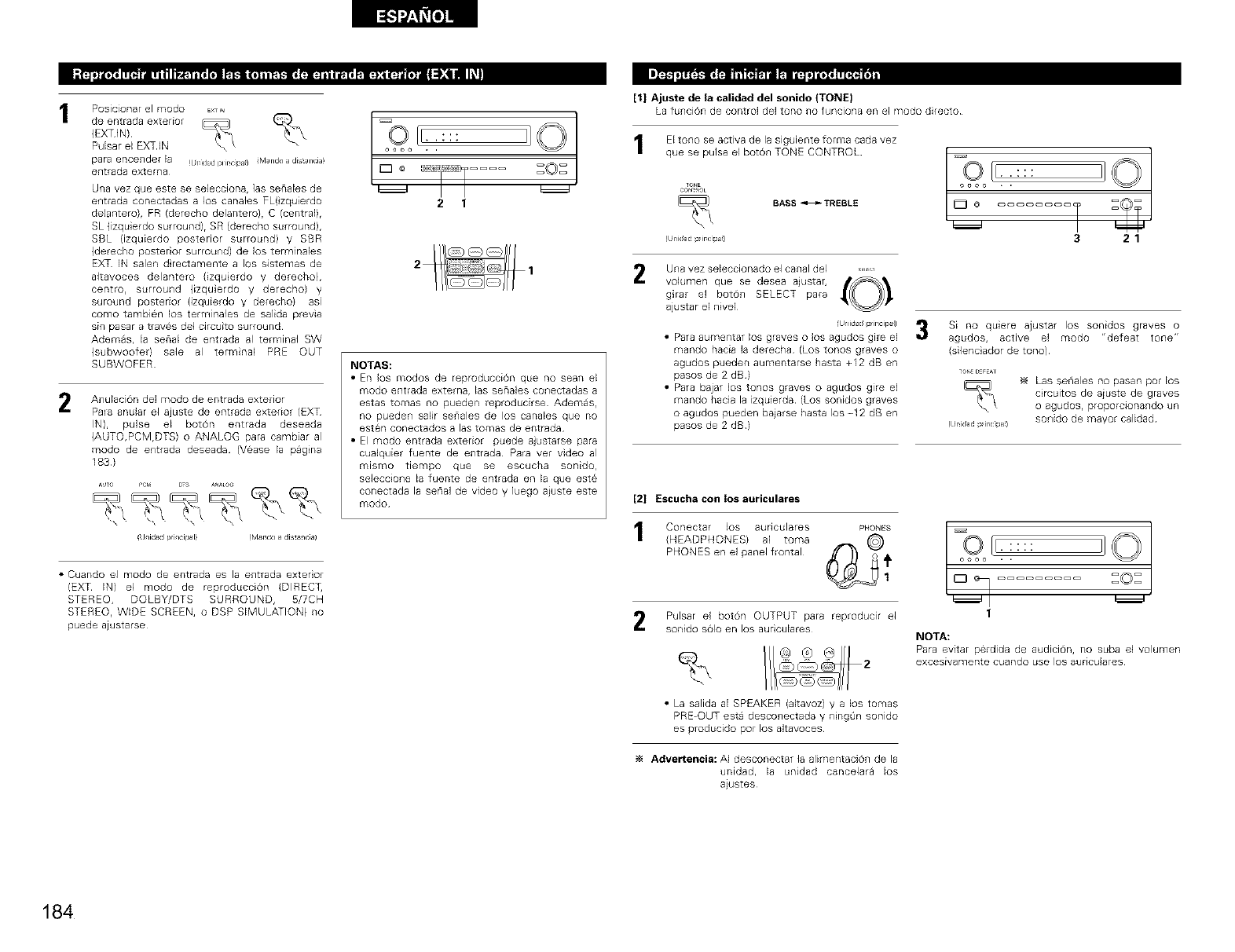
JL_1_L'a_ t_lmr41ml m Li_il"t_ tl"t&_fl'a_
2
Posicionar el modo EXTI_
de entrada exterior
(EXTIN)
Pulsar el EXTIN
para encender la (/r 1dadplircipa) {Mandoadistancia)
entrada extema
Una vez que este se selecciona, las senales de
entrada conectadas a los canales FL(zquierdo
de[antero), FR (derecho delantero}, C (centrall,
SL (izqu erdo surround), SR (derecho surround),
SBL (izquierdo posterior surround) y SBR
(derecho posterior surround) de los terminales
EXT IN salen d rectamente a los sistemas de
altavoces delantero (izquerdo y derecho),
centro, surround (izquerdo y derechol y
suround posterior (izquierdo y derecho} asi
como tambien los terminales de salida previa
sin pasar a traves de1 circuito surround
Ademas, la senal de entrada al terminal SW
(subwoofer) sale al terminal PRE OUT
SUBWOFER
AnulaciOn del modo de entrada exterior
Pala anular el ajuste de entrada exterior (EXT
IN), pulse el boron entrada deseada
(AUTO,PCM,DTS) o ANALOG para cambiar al
modo de entrada deseada (Vease la pagna
183)
(Uaida_dpriacipal} fMa_r_do_distaflc_a)
• Cuando el modo de entrada es la entrada exterior
(EXT IN) el modo de reproduccion (DIRECT,
STEREO, DOLBY/DTS SURROUND, 5/7CH
STEREO, WIDE SCREEN, o DSP SIMULATION) no
puede ajustarse
I=oIt:
o:o.-:::
io zoT....
21
NOTAS:
•En los modos de reproduccion que no sean el
modo entrada extema, las senales conectadas a
estas tomas no pueden reproducirse Ademas,
no pueden salir senales de los canales que no
esten conectados alas tomas de entrada
• El modo entrada exterior puede a}ustarse para
cualquier fuente de entrada Para ver video al
mismo tiempo que se escucha sonido,
seleccione la fuente de entrada en la que este
conectada la senal de video y luego aiuste este
modo
[1| Ajuste de la calidad del sonido (TONE}
La funcion de control del tono no funciona en el modo directo
El tono se activa de la siguiente forma cada vez
que se pulsa el botOn TONE CONTROL
_ONE
COr__OL
BASS _TREBLE
!Unidad pdr_clpa_l
=,O{r:_:::
o_oo *
321
2Una vez seleccionado el canal del ......
volumen que se desea ajustar, _
girar el boton SELECT para
ajustar el nivel
Ulidd p incipal}
• Para aulnentar los graves o los agudos gire el
mando hacia la derecha (Los tonos graves o
agudos pueden aumentarse hasta +12 dB en
pasos de 2 dBI
• Para bajar los tonos graves o agudos gire el
mando hacia la izquierda (Los sonidos graves
o agudos pueden bajarse hasta los -12 dB en
pasos de 2 dBI
Si no quiere ajustar los sonidos graves o
agudos, active el modo "defeat tone"
(silenciador de tono)
Las seriales no pasan por los
circuitos de aiuste de graves
o agudos, proporcionando un
sonido de mayor calidad
[2| Escucha con los auriculares
C0necta_ los a LlricLlla re S pH0_S
(HEADPHONES/ al toma (_
PHONES en el panel frontal @__ 1
Pulsar el boton OUTPUT para reproducir el
sonido solo en los audculares
1
NOTA:
Para evkar perdida de audicJon, no suba el volumen
excesivamente cuando use los auriculares
• La salida al SPEAKER (altavoz) y a los tomas
PRE-OUT esta desconectada y ningOn sonido
es producido pot los altavoces
Advertencia: AI desconectar la alimentaciOn de la
unidad, la unidad cancelara los
aiustes
184
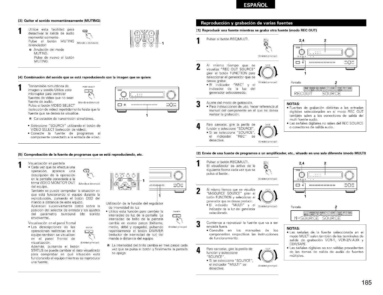
J3] Quitar el sonido momentaneamente (MUTING)
Utilice esta facilidad para
desactivar la salida de audio
momentaneamente
Pulse el botOn MUTING
(silenciador)
AnulaciOn del modo
MUTING
Pulse de nuevo el boron
MUTING
fM_ndoadistanc_a)
J4] Combinaci6n del sonido que se esta reproduciendo con la imagen que se quiere
Transmisi6n simult4nea de VIDE€8ELEC]
interruptorimageny sonidOparacontrolarUtiliceeste Qo_oo
fuentes de video que no sear . .
fuente de audo ([Vland_adistancH! r
Pulse el boron VIDEO SELECT /_:_ _
(selecciOn de video) repetidamente hasta que la
fuente que se desea se visualice 1
_4 Cancelaci6n de transmisi6n simultanea
• Seleccione "SOURCE" utilizando el boton de
VIDEO SELECT (selecciOn de video)
• Conecte la fuente de programas al
componente conectado a la entrada de video
ZOZ
[1| Reproducir una fuente mientras se graba otra fuente (modo REC OUT)
Pulsar el boron REC/MULTI _LTI
(Uaid_dprincipal]
AI mismo tiempo que se
visualiza "REC OUT SOURCE"
gkar el boton FUNCTION para
seleccionar e] generador que se
desee grabar j/idad principal)
• El indicador "REC" y el
indicador de la luz del
generador 5eleccionado
Aiuste del modo de grabaci6n
• Para instrucciones de u5o, hacer referencia al
manual del cornponente en el que se desea
realizar la grabacion
Para cancelar, gire la pe Ila de _ _ _
funci6n y seleccione "SOURCE"
• Si se selecciona "SOURCE",
el indicador r'REC" se
desactiva j/idad principal)
2,4 2
I,1©
1
Pantalla 2
RE:COUT :_i:::ii...iB:i'::E
NOTAS:
• Fuentes de grabacion distintas alas entradas
digitales seleccionadas en el modo REC OUT
tambien salen a los conectores de salida del
multi fuente audo
• Las senales d gtales no salen de] REC SOURCE
o conectores de salida audio
J5] Comprobaci6n de la fuente de programas que se esta reproduciendo, etc.
Visualizacion en pantalla
• Cad8 vez que s@ efectua una
operacE6n, aparece una
descripci6n de ia operaci6n
en la pantalla conectada a la
toma VIDEO MONKOR OUT (Mando disalcia!
del equpo
Tambien se puede comprobar la situacion en
que esta funcionando el equipo durante la
reproducci6n, pulsando el boton OSD del
mando a distancia de este equipo
Aparecen suceslvamente datos sobre la
posici6n del selector de entrada y los ajustes
del parametro surround (de sonido
envolvente)
Visualizacion en e] panel frontal
• Las descrpc4ones de las s_us
operaciones realizadas en el
equlpo tambien se visualizan
en el panel frontal de
visualizaciOn (u_l dad pr Icipali
Ademasr pulsando el boton
STATUS se puede cambiar el dato visualizado
para comprobar en que situacion esta
funcionando el equipo mientras se reproduce
una fuente
o7
Utilizaci6n de la funcion del regulador
de intensidad de luz
• Utilice esta funci6n para cambiar la
intensidad de luz de la pantalla La
intensidad de bdllo de la pantalla
cambia en cuatro pasos (bdllante,
medio, debil y apagado), pubando
repetidamente el bot6n DIMMER
(reductor de intensidad de luz) del
mando a distancia del equipo
101
(U_lidadpdncip_flI
La ntensidad del bdllo cambia en tres pasos cada
vez que se pulsa el boron y finalmente la pantalla
se apaga
[2| Envio de una fuente de programas a un amplificador, etc., situado en una sala diferente (mode MULTI)
2
3
4
Pulsar el boton REC/MULTi _
El visualizador se activa de la
slguiente forma cada vez que se
pulsa el boron
J/idadprincipal)
AI mismo tiempo que se visualiza
"M-SOURCE SOURCE" gi_ar el
bot6n FUNCTION y sebccionar el
generador que se desee producir
• El indicador "MULT]" y el J/id_dprincipal)
indicador de la luz del generador
se}eccionado
ComienGe a reproducif la fuent@ que va a set
enviada fuera
• ConsuRe en los manuales de los
comport@rites respectivos las instruGcior_es
de funcionamiento
Para cancelar, gire la per lla de
funci6n y sebccione
"SOURCE"
• Si se sebcciona "SOURCE",
el indicador "MULTi" se
desactiva (Uaidaidprincipal)
2,4 2
1
Pantalla 2
I I
NOTAS:
• Las senales de la fuente sebccionada en el
modo MULTI salen tambi@_ de los terminales de
salida de grabacion VCR_I, VCR_2/VAUX y
CDR/TAPE
• Las senales digtales no son salidas procedentes
de las tomas de salida de audio de fuentes
m@ltiples
185
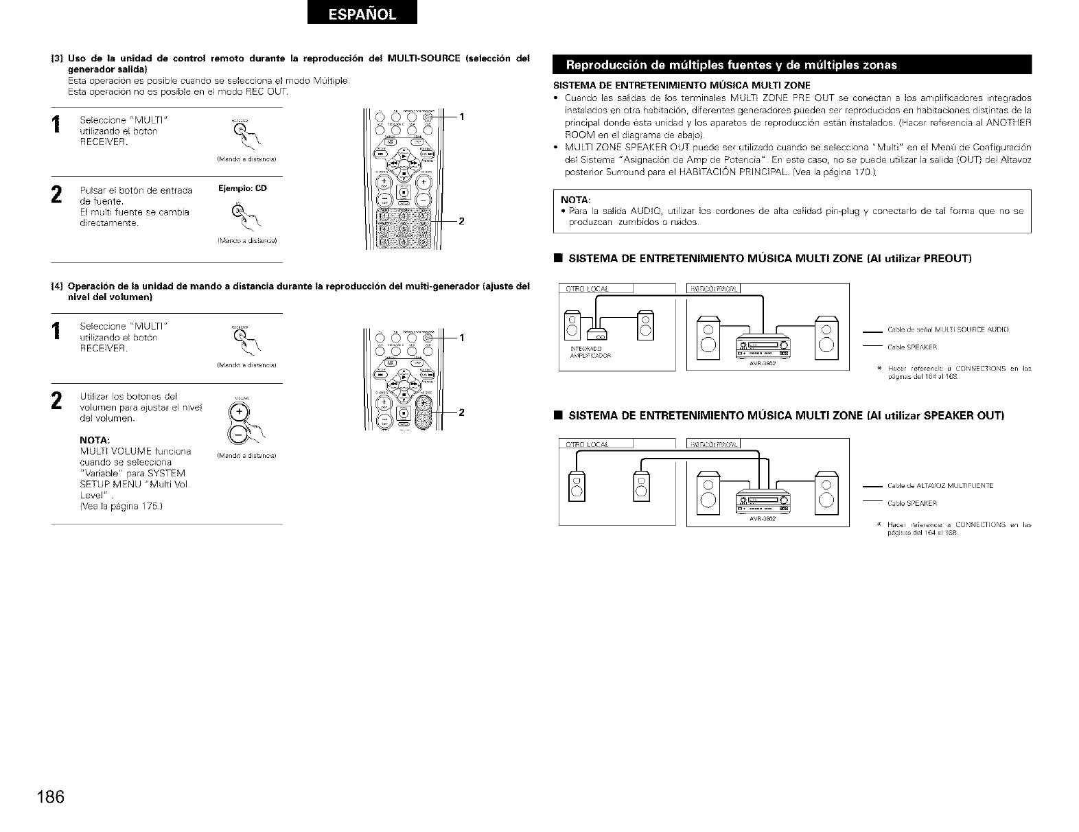
13] Uso de la unidad de control remoto durante la reproduccidn del MULTI-SOURCE (seleccion del
generador salida}
Esta operaci6n es posible cuando se selecciona el rnodo MGItiple
Esta operacion no es posible en el modo REC OUT
Seleccione "MULTI"
utilizando el boron
RECEIVER
I[vI nd? a disi8 nc l)
Pulsar el boton de entrada Elemplo: CD
de fuente
El multi fuente se cambia
directamente
tMrdo i dist r ca)
1
2
14] Operacidn de la unidad de mando a distancia durante Ia reproduccion del multi-generador (ajuste del
nivel del volumen)
Seleccione "MULTI"
utilizando el boron
RECEIVER
I[vI nd? a disi8 nc l)
Utilizar los botones del
volumen para ajustar el nivel
del volumen
NOTA:
MULTI VOLUME funciona
cuarldo se seleccJona
r'Variable" para SYSTEM
SETUP MENU "Multi Vul
Level"
(V_a la pagna 175}
fM_mdoadistanc_a)
SISTEMA DE ENTRETENIMIENTO MOSICA MULTI ZONE
• Cuando las salidas de los terminales MULTI ZONE PRE OUT se conectan a los amplif cadores integrados
instalados en otra habitaciOn, diferentes generadores pueden set reproducidos en hab taciones d stintas de la
principal donde esta unidad y los aparatos de reproducciOn estan instalados (Hacer referencia al ANOTHER
ROOM en el diagrama de abajo)
• MULTI ZONE SPEAKER OUT puede set utilizado cuando se selecciona "Multi" en el Men8 de ConfiguraciOn
de1 Sistema "AsignaciOn de Amp de Potencia" En este caSOr no se puede utilizar la salida {OUT) del Altavoz
posterior Surround para el HABITACION PRINCIPAL (Vea la pagina 170)
NOTA:
• Para la salida AUDIO, utlizar los cordones de alta calidad pin-plug y conectado de tal forma que no se
produzcan zumbidos o ruidos
•SISTEMA DE ENTRETENIMIENTO MOSICA MULTI ZONE (AI utilizar PREOUT)
AVR_SS02
m Cable de se_lal MULTI SOURCE AUDIO
-- Cable SPEAKER
< IIJce_ refere/cia J CONNECTONS en I_s
p9m_s de1164 al /68
•SISTEMA DE ENTRETENIMIENTO MOSICA MULTI ZONE (AI utilizar SPEAKER OUT)
OTRO LOCAL I
AVR_SS02
m Cable de ALT/_OZ MULTIFUENTE
m Cable SPEAKER
_ Hacer re_erencB _ CONNECTIONS en las
p_9mas de1164 al /68
186
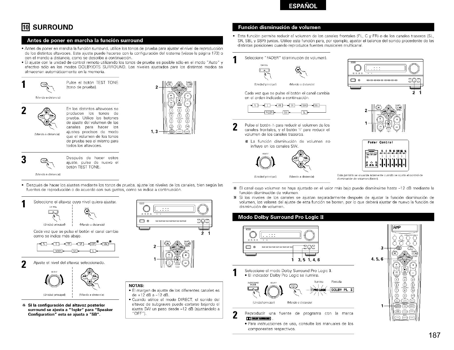
[] SURROUND
• Antes de poner en marcha la funci6n surround, utifice los tonos de prueba para ajustar el nivel de reproducciOn
de los distintos altavoces Este ajuste buede hacerse con la configuraci6n del sistema (vease la pagna 173) o
con el mando a distancia, como se describe a continuaci6n
• EEajuste con la unidad de control remoto utilizando los tonos de prueba es posibb s6lo en el modo "Auto" y
efectivo s6lo en los modos DOLBY/DTS SURROUND Los niveles ajustados para los distintos modos se
almacenan automat carnente en la memofia
Pulse el boton TEST TONE
(tono de prueba}
@lrd_ adist ic J)
En los distintos altavoces se
broducen los tonos de
brueba Utilice los botones
de ajuste del volumen de los
canaJes bara hacer los
ajustes precisos de modo
(Maid° dis Ncia! que el volumen de los topos
de prueba sea el mismo para
todos los alLavoces
2
1,3
(Z) @ ®
Co®@
Despues de hacer estos
ajuste, pulse de nuevo el
boron TEST TONE
(Mando disalda!
• Deopueo de hacer los ajustes reed ante los tonos de pruebar aiuste los niveles de los canaleo, bien seg@n las
fuentes de reproducciOn o de acuerdo con sus gustos, como se indica a cont nuaGion
Sebccione el altavoz cuyo niveJ quiera aiustar
C_VOL
(Un dad pr ncil_ I) (Man(Soa d stal_ci/
Carla vez que se puJsa el boron el canal cambia
como se indica mas abaio
oooa . .
Jo°
21
ht_l_ r_ II';II_,,i._ I _'t/! It_j-t'41111
r_OEP 3_, 3L
Ajuste el nivel del altavoz sebccionado
(U_l dad rJr icil_ I! !Mando ad stanci,=_
Si la configuraci6n del altavoz posterior
surround se ajusta a "lspkr" para "Speaker
Configuration" esta se ajusta a "SB".
NOTAS:
•El rnargen de ajuste de los diferentes carlales es
de +12 dB a-12 dB
• Cuando utilice el modo DIRECq] el sonido del
altavoz de subgraves puede cortarse baiando el
ajuste SW un paso desde -12 dB (aiustandolo a
"OFF"I
• Esta funcion permite reducir el volumen de los canales frontales (PL, C y FR) o de los canales traseros (SL,
SR, SBL y SBR) juntos Utilice esta funcion parar por ejem@o, aiustar el balance del sonido procedente de las
distintas posiciones cuando reproduzca fuentes musicales multicanal
Seleccione "FADER" (disminuci6n de volume@
c_vo
(Unida_dpril_cipal) tMamdoa distar_c}a)
Cada vez que se pulse el bot6n el canal cambia
en el orden indicado a continuacbn
oooo . .
ID°
21
Pulse el boton zpara reducir el volumen de los
canales frontales, y el boron para reducir el
volumen de los canales traselos
La funci6n disminuciOn de volumen no
infiuye en los canales SW
(Unid_dpril_cipal) ffvl_mdoadist_r_c}a)
Fader Control i/FLC FI N _Bl_ll_.
+++4i+i
'"' TI'
°1°1.1.1....
Es_a pa nalla se visualiza solall en e c lando se J J_ el cornro de
dsl 1Jr lJcN_ de vo J )el _el/
El canal cuyo voWmen se haya ajustado en el valor mas bajo puede dbmin@rse hasta -12 dB mediante la
funci6n disminucion de volumen
Si los niveles de los canales se aiustan separadamente despues de ajustar la funcion disminuci6n de
volumen, los valores del ajuste de esta funci6n se borran, pot Io que debera ajustar de nuevo la funci6n de
disminuci6n de volumen
3
1 3,5 1,4,6 4,5,6
Seleccione el modo Dolby Surround Pro Logic I]
•El illdicador Dolb¥ Pro Logic se ilum[lla
I_Jl_lr_ Pantalla
'"
J/ I \"
(Unidad r_r_r_cir_l_ !Mal_(_(_ a diStal_Cl_l
meproduci[ u_a fuente de programa con la mBrc8
• P_ra instfucciones de uso, consult@ los manuBles d@ los
componentes r@spectivos
1
_MP
0000
(Z) @ ®
@,@
©®®
187
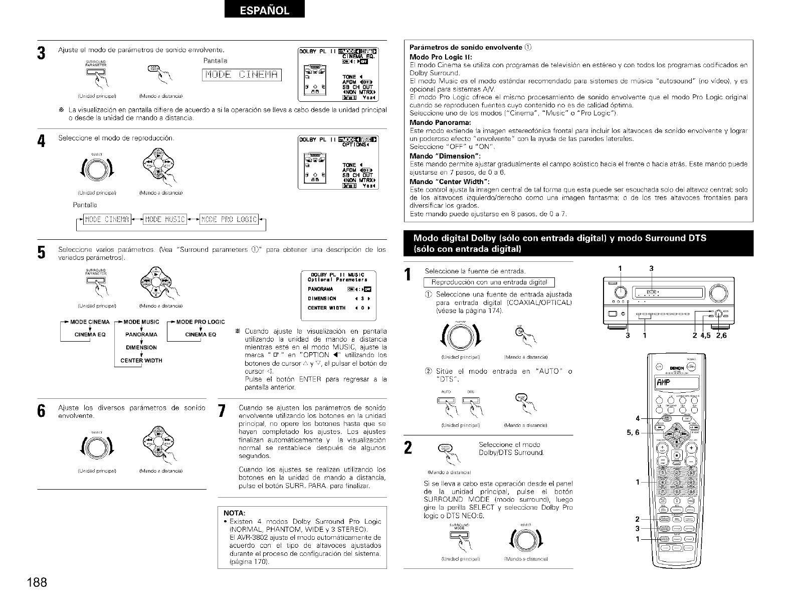
3
4
Ajuste eIp_a_.__RSURRO,sm°d° de parametros de sonido envolventepantalla F OLBYBPLI I _4=ClNF_I.It_EQ.
I i'i0DE C]:i"iENFi I TONE'
SB CH OUT
_INC¢IMTRX_
&Jnidadpr_ncip_l_ (Mandoadis_anciaI _ Yaa4
La visualizaci6n en pantalia difiere de acuerdo a si la operaci6n se (leva a cabo desde la unidad principal
o desde la unidad de mando a distancia
Seleccione el modo de reproducciOn
iJlidad pr}lcip b iMando disalcia!
Pantalla
[_ ":(:E:'_:I::: liE' '_'l}_[ 'Id'_: :[ I_]
FOLBY P_ I I
OPT IC!_IS<
AFOM 4_]_
SB CH OUT
(NDN MTRX_
Pardmetros de sonido envolvente :1
Modo Pro Logic II:
El modo Cinema se utiliza con programas de televisi@_ en estereo y con todos los programas codiflcados en
Dolby Surround
El modo Music es el modo estandar recomendado para sistemas de m_sica "autosound" (no video), yes
opcional para sistemas AH
El modo Pro Logic ofrece el mismo procesamlento de sonido envolvente que el modo Pro Logc original
cuando se reproducen fuentes cuyo contenido no es de calidad Optima
Seleccione uno de los modos ("Cinema". "Music" o "Pro Logic")
_t_ando pan oi*a _il a:
Este modo extiende la magen estereofOnica frontal para induir los al[avoces de sonido envolvente y Iograr
un poderoso efecto "envolvente" con la ayuda de las paredes ]aterales
Seleccione "OFF" u "ON"
Mando "Dimension":
Este rnando perrnite ajustar graduaknente el campo ac_ist co hacia el frente o hacia atras Este mando puede
ajustarse en 7 pasos, de 0 a 6
Mando "Center Width":
Este control ajusta la imagen central de tal forrna que esta puede set escuchada solo del altavoz central; solo
de los altavoces izquierdo/derecho como una imagen fantasma; o de los tres altavoces frontales para
diversificar los grados
Este mando puede ajustarse en 8 pasos, de 0 a 7
Seleccione vanos parametros (Yea "Surround parameters (i}" para obtener una descdpcion de los
vadados parametros)
SURROU_
&Jnidad pr_ncipal_ (Mando adis_anciaI
I °,.T°.
[_ WIDTH
DOLLY pL II MUSIC
Optl0nll Plrlmeterl
PANORAk_ _:klt_
DIMENSION _3
CENTER WIDTH _ 0
Cuando ajuste la visualizaci6n en pantalla
utilizando la unidad de mando a distancia
mientras este en el modo MUSIC, ajuste la
marca " E_" en "OPTION _" utilizando los
botones de cursor, y ', al pulsar el bot6n de
cursor
Pulse el bot6n ENTER para regresar a la
pantalla anterior
Ajuste los diversos parametros de sonido
envolvente
{J/idad pr lip I_ {Mando di an ia!
Cuando se ajusten los parametros de sonido
envolvente utilizando los botones en la unidad
principal, no opere los botones hasta que se
hayan completado los ajustes Los ajustes
finalizan automaticamente y la visualizaciOn
normal se restablece despues de algunos
segundos
Cuando los ajustes se realizan utilizando los
botones en la unidad de mando a distancia.
pulse el botOn SURR PARA para finalizar
NOTA:
• Existen 4 modos Dolby Surround Pro Logic
(NORMAL. PHANTOMr WDE y 3 STEREO)
El AVR-3802 aiusta el modo automaticamente de
acuerdo con el tipo de altavoces ajustados
durante el proceso de configuraci6n del sistema
(pagina 170)
2
Seleccione la fuente de entrada
[ ReproducciOn con una entrada digital I
@ Seleccione una fuente de entrada ajustada
para entrada digital {COAXIAL/OPTICAL)
(v@ase la pagina 174}
J lidad pril_ci _all (M, ndo a distanc a)
@ SitOe el modo entrada en "AUTO" o
"DTS"
AUTO _,TS
(Unidad pril_cipali !Mal_dO a d_star_cla)
Seleccione el modo
Dolby/DTS Surround
_Mar_do a dista ndal
Si se Ileva a cabo esta operaciOn desde el panel
de la unidad principal, pulse el bot6n
SURROUND MODE (modo surround), luego
g_re la perilla SELECT y seleccione Dolby Pro
Iogc o DTS NEO:6
MO_E
(Unidad pril_cipali (Mando ad_stancia_
3 1 2 4,5 2,6
flHP ]
O © 'O_ '
©'©O ©
188
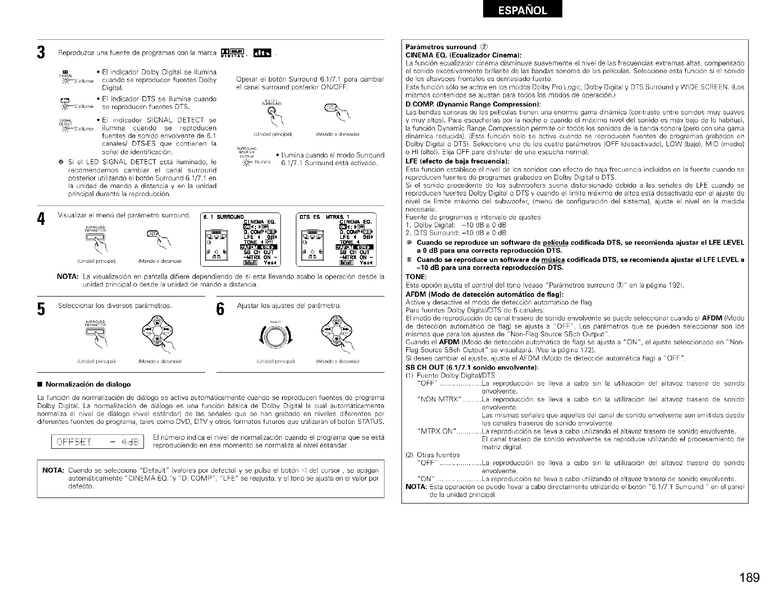
Reproduzca una fuente de programas con la marca _.T_].L,
4
5
Digital
,.A_ • El indicador SIGNAL DETECT se
DE_EC_
_O_Sllurle ilumina cuando se reproducen
fuentes de sonido e_wolvente de 61
canales/ DTS-ES que contienen la
senal de ide_tificaci6n
Si el LED SIGNAL DETECT esta iluminado, le
recomendamos cambiar el canal surround
posterior utilizando el boton Surround 61/71 en
la unidad de mando a distancia yen la unidad
pr ncipal durante la reproduccidn
Operar el boron Surround 61/71 para cambiar
el canal surround posterior ON/OFF
{Url dad pr 1tip II {[VI_ rid ) a dis _rlci ])
_CKC_
o,,_u • Ilumina cuando el modo Surrou_ld
;c_ Ilurlir'a 61/71 Surround esta act vado
Visualizar el menO del 3arametr° surr°und /ll" 1 SURROUN0clN_ EQ"..........SURRO_U _=1 _40. C(3MP<_:_ [ 03-S ES MTRXC_IIEMAEQ'_ _4O,COMP4_:b
LFE i 0d6_
SB CH OUT SB CH OUT
-MTRX ON - -MTRX ON -
iJ/idadprlipfll iMando di alia) _ YeI ( _ YeS4
NOTA: La visualizacidn en pantalla difiere depend endo de si esta Ilevando acabo la operacidn desde la
unidad principal o desde la unidad de mando a distancia
Seleccionar los diversos parametros 6Ajustar los ajustes del parametro
SURROU_
{J_idad prrlcipll {M_rldo dis_lcia) {J_idad prrlcipll {[vl_rld? a dis_rlci])
•Normalizacidn de dialogo
La funcion de normalizacion de d alogo se activa automaticamente cuando se reproducen fuentes de programa
Dolby Digilal La normalizacidn de dialogo es una funcidn basica de Dolby Digital la cual automaticamente
normaliza el nivel de dialogo (nivel estandar} de las seriales que se ban grabado en niveles diferentes por
diferentes fuentes de programa, tales como DVD, DTV y olros formatos futuros que utilizaran el boton STATUS
.................................... I El nOme_o indica el nivel de normalizacidn cuando el programa que se esta
i i..,i. ..... q,.iiq reproduciendo en ese momento se nofrnsliza 81nivel estandar
NOTA: Cuando se selecciona "Default" (valores por defecto) y se pdsa el botdn I del cursor, se apagan
automaticamente "CINEMA EQ "y "D COMP", "LFE" se reajusta, y el tono se ajusta en el valor por
defecto
Pardmetros surround _2
CINEMA EQ, (Ecualizador Cinema}:
La funcion ecualizador ci_ema disminuye suavernente el nivel de las frecuencias extremas altas rcornpensado
el sonido exceswamente bdllante de las bandas so_oras de las peliculas Seleccione esta funciOn si el so_fido
de los altavoces frontales es demasiado fuerte
Esta funcidn sdlo se activa en los modos Dolby Pro LogiCr Dolby Digital y DTS Surround y WIDE SCREEN (Los
mismos contenidos se ajustan para todos los modos de operaciOn )
D.COMP, (Dynamic Range Compression}:
Las bandas sonoras de las peliculas tienen u_a enorme garna dinamica (co_traste entre sonidos muy suaves
dinamica reducida) (Esta funcidn solo se activa cuando se reproducen fuentes de programas grabados en
Dolby Dgtal o DTS) Seleccione uno de los cuatro parametros (OFF (desactivado), LOW (bajo), MID (medio)
o HI (alto)) Elija OFF para disfrutar de una escucha normal
LFE (efecto de baja frecuencia):
Esta funcidn establece el nivel de los sonidos con efecto de baja frecuencia i_cluidos en la fuente cuando se
reproducen fuentes de programas grabados en Dolby Digital o DTS
Si el sonido procedente de los subwoofers suena distorsionado debido alas senales de LFE cuando se
reproducen fuentes Dolby Dig tal o DTS y cuando el I_mite maximo de altos esta desactivado con el ajuste de
nivel de Ifmite maximo del subwoofer, (menQ de configuracidn del sistema}, ajuste el nivel en la medida
necesana
Fuente de programas e intervalo de aiustes
1 DolbyDgtak -10dBa0dB
2 DTS Surround: -10 dB a 0 dB
Cuando se reproduce un software de pelic_la codificada DTS, se recomienda ajustar el LFE LEVEL
a 0 dB para una correcta reproduccidn DTS,
Cuando se reproduce un software de mt_sica codificada DTS, se recomienda ajustar el LFE LEVEL a
-10 dB para una correcta reproduccidn DTS,
TONE:
Esta opci6_ ajusta el co_trol del to_o (vease "Pararnetros surround 3" en la pagina 192)
AFDM (Modo de deteccidn automatico de flag}:
Active y desactive el modo de detecciO_ automatico de flag
Para fuentes Dolby Dig tal/DTS de 5 canales:
El modo de reproduccion de canal trasero de sonido envolvente se puede seleccionar cuando el AFDM (Modo
de deteccion automatico de flag) se ajusta a "OFF" Los parametros que se pueden seleccionar son los
mismos que para los ajustes de "Non-Flag Source SBch Output"
Cuando el AFDM (Modo de deteccion automatica de flag) se ajusta a "ON", el ajuste seleccionado en "Non-
Flag Source SBch Output" se visualizara (Vea la pagina 172)
Si desea cambiar el ajuste, ajuste el AFDM (Modo de detecci6n automat ca flag) a "OFF"
SB OH OUT (6.1/7,1 sonido envolvente):
(1) Fuente Dolby DigitaVDTS
"OFF" ..................... La reproduccidn se Ileva a cabo sin la utilizaci6n del altavoz trasero de sonido
envolvente
"NON MTRX" ......... La reproduccidn se Ileva a cabo sin la utilizaci6n del altavoz trasero de sonido
envolvente
Las mismas seriales que aquellas de1 canal de sonido envolvente son emitidas desde
los canales traseros de sonido envolvente
"MTRX ON" ............ La reproduccidn se Ileva a cabo utilizando el altavoz trasero de sonido envolvente
El canal trasero de sonido envolvente se reproduce ut lizando el procesamiento de
matriz dig tal
(2) Otras fuentes
"OFF" ..................... La reproduccidn se Ileva a cabo sin la utilizaci6n del altavoz trasero de sonido
envo;vente
"ON" ....................... La reproduccidn se Ileva a cabo utilizando el altavoz trasero de sonido envolvente
NOTA: Esta operacidn se puede Ilevar a cabo directamente utilizando el boton "61/71 Surround " en el panel
de la unidad principal
189
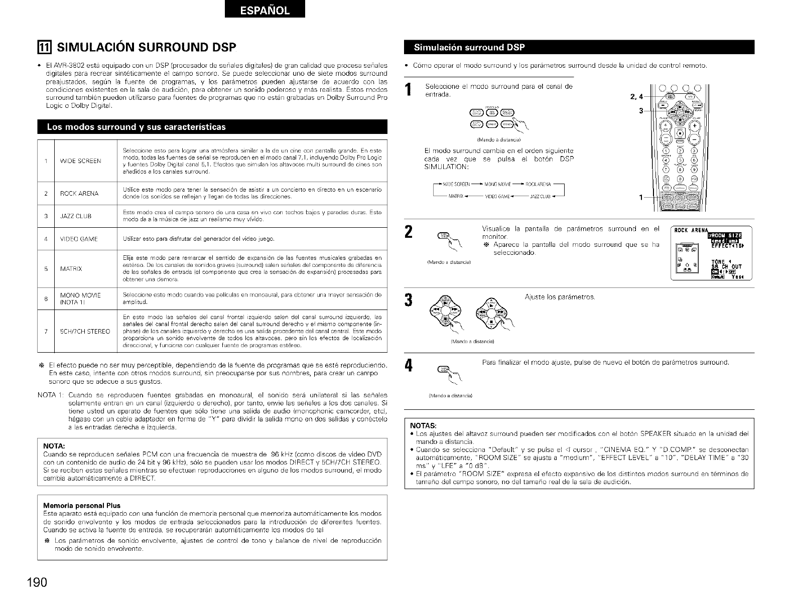
[] SIMULACION SURROUND DSP
• E) AVR-3802 esta equipado con un DSP (procesador de senales digita)es) de gran calidad que procesa sena)es
digitales para recrear sinteticamente el campo so_oro Se puede seleccionar uno de siete modos surrou_d
preajustados, segt_n la fuente de programas, y los parametros pueden ajustarse de acuerdo con las
cond cio_es existentes en la sala de audiciO_, para obter_er un so_fido poderoso y mas realista Estos modos
surround tambien pueden uti)izarse para fuentes de programas que no estan grabadas en Dolby Surround Pro
Logic o Dolby Digital
SeleccioTse esto para Iogar una atmosfe a sirnlar a la de un c[ne CO_lpa_tala grande En este
1 WIDE SCREEN mode, todas las fuentes de serla_ se reproducen eT1el modo canal 7,1, irlcluyeTldo Dolby Pro Logic
y fuentes Dolby Digital callal _,1 Efectos que s[m_lan los altavoces multi surrouTld de tines son
anadidos a los canapes surround
Ut[lice este modo para t_ne_ la seT_saci6n de as[Stl_ a uT_concie_to eT_di_ecto en _n escena_[o
2 ROCK ARENA donde los son[dos me reflejan y legan de todas las d reccioTles
Este modo cea el carnpo soTsoro de una casa en vivo con techos baos y paredes duras Este
3 JAZZ CLUB modo da a a ¥_/isica de iazz un real smo muy v_vdo
4 VIDEO GAME Ut[I zar esto para disfrutar de geTlerador del video juego
E]ia este rnodo para remarcar el sentido de expansi6n de las fuentes r'lus[oales grabadas en
estereo De os ca_sales de son dos graves {surround) saen sef'ales de cor'lponeTste de d[ferencia
B MATRIX de las senales de eTltrada {el compo/er/te que crea la seTlsaci6r/ de expansi61) procesadas para
obtene u/a demora
MONO MOVIE Selecclof_e este modo cua/do yea peliculas e/¥1o/oaura_, para obtener una mayo sensac 6/de
6{NOTA 1 ) ar,/plit ud
Erl este modo 1as sef'aes de cana frolltal izquerdo saen del cana surround [zquierdo, las
senales del canal frofstal derecho sa]eTs del canal surround derecho y el mismo compo/ente (n
7 BCH/TCH STEREO phase) de los canales [zquierdo y derecho es una salda procedente de1 canal centra] Este modo
proporc[ona un son[do eTsvolveTste de todos los altavoces, pero sin los efectos de Ioca[zaci6n
di eccional, y funciona con cua quie fuente de p_ogramas est@reo
El efecto puede _o ser muy perceptible, dependiendo de )a fuente de programas que se este reproduciendo
En este caso, intente con otfos modos surround, sin preocuparse pot sus hombres, para crear un campo
sonoro que se adecue a sus gustos
NOTA 1: Cuando se reproducen fuentes grabadas en monoaural, el sonido sera unilateral si las senales
solamente entran en un canal {izquierdo o derecho), por tanto, envie las senales a los dos canales Si
tiene usted un aparato de fuentes que solo tiene una salida de audo (monophonic camcordeh etc),
hagase con un cable adaptador en forma de "Y" para dividir la salida mono en dos salidas y conectelo
alas entradas derecha e izquierda
NOTA:
Cuando se reproducen seriales PCM con u_a frecuencia de muestra de 96 kHz (como discos de video DVD
con un contenido de audio de 24 bit y 96 kHz>, solo se pueden usar los modos DIRECT y 5CH/7CH STEREO
Si se reciben estas senales mientras se efectuan reproducciones en alguno de los modos surround, el modo
cambia automaticamente a DIRECT
Memoria personal Plus
Este aparato esta equipado co_1una fu_lci0n de rnemorla personal que rnemoriza aut on_laticamel]te los rnodos
de SO_lidOenvolvente y )os modos de e_ltrada seleccio_ladOs para la introducci6n de d fere_ltes fuentes
Cuando se act)va la fue_lte de entrada, se recuperara_l automaticame_lte los modos de tal
Los parametros de sonido envolvente, aiustes de control de tono y balance de nivel de reproduccion
modo de sonido envolvente
• Como operar el modo surround y los parametros surround desde la unidad de control remoto
Seleccione el modo surround para el canal de
entrada
QQ_
iMando a dista ncia)
El modo surround cambia en el orden siguiente
cada vez que se pulsa el boton DSP
SIMULATION:
OOOO
3
1
2/ROCK ARENA_
!r_l_d _ _ _!i_t_i_l TONE
L _ Ye"
3@@Ajus,e,os0ar me ro
(M:mdo a di_r_ci_)
Rata finalizar el modo ajuste, pulse de nuevo el boton de parametros surround¸
iM_ndo _ dist_ ncia)
NOTAS:
• Los ajustes del altavoz surround pueden ser modificados con el bot0n SPEAKER situado en )a unidad del
mando a distancia
• Cuando se selecciona "Default" y se pulsa el _ cursor ,"C)NEMA EQ" Y "D COMP" se desconectan
automaticamente, "ROOM SIZE" se aiusta a "medium", "EFFECT LEVEL" a "10", "DELAY TIME" a "30
ms" y "LFE" a "0 dB"
• El parametro "ROOM SIZE" expresa el efecto expansivo de los distintos modos surround en term)nos de
tamano del campo sonoro, no del tama_o real de )a sala de audici6n
Visualice la pantalla de parametros surround e_ el
monitor
Aparece la pantalla del modo surround que se ha
seleccionado
190
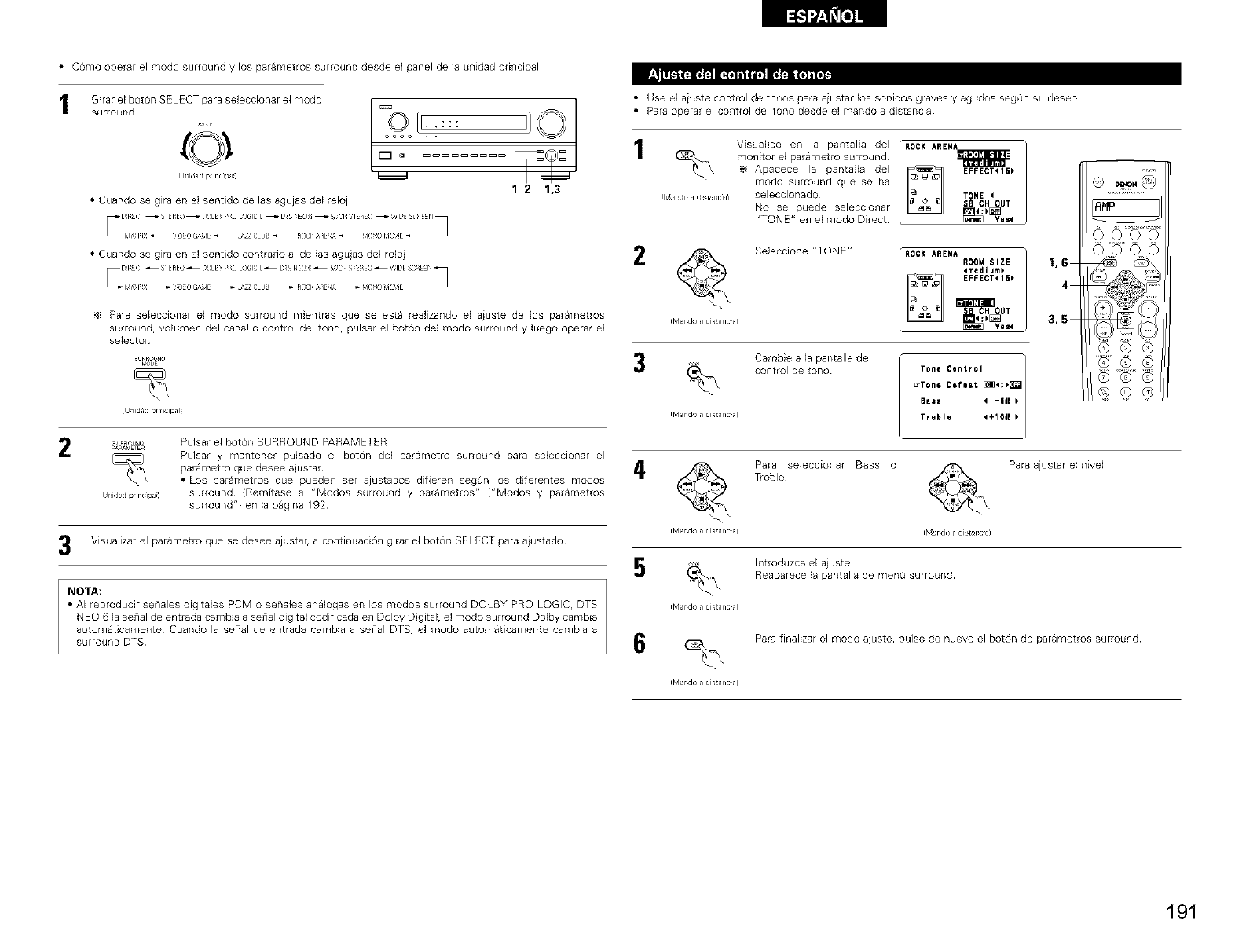
• C6mo operar el modo surround y los parametros surround desde el panel de la unidad principal
Girar el boton SELECT para seleccionar el modo / __
surround [ooookl[ [:::
(O I°°
R r IdJd plir clpJ)
1 2 1,3
• Cuando se glra en el sentido de las agujas del reloj
• Cuando se glra en el sentido contrario al de las agu}as del relo}
Para seEeccionar el modo surround mientras que se esta realizando el aiuste de los parametros
surround, voEumen de1 canal o control de1 tono, pulsar el lsotOn de1 modo surround y luego operar el
selector
_,_E
iUnidadpr_ncip_li
_-A_I_%_ Pulsar el boron SURROUND PARAMETER
_\ Pulsar y mantener pulsado el boron de] parametro surround para seleccionar el
parametro que desee ajustar
• Los parametros que pueden set ajustados difieren segOn los dferentes modos
(Ul_ida/Jpirc]pa) surround (Remitase a "Modos surround y parametros" ("Modos y parametros
surround") en la pagna 192
3Visualizar el parametro que se desee ajustar, a continuacion girar el boton SELECT para aiustado
NOTA:
•AI reproducir senales digitales PCM o senales a_lalogas en los modos surround DOLBY PRO LOGIC, DTS
NEO:6 la senal de entrada cambia a se_al digital codificada e_ Dolby D gital, el modo surround Dolby cambia
automaticamente Cuando la serial de entrada cambia a se_al DTS, el modo automaticamente cambia a
surround DTS
• Use el aiuste control de tonos para aiustar los sonidos graves y agudos segOn su deseo
• Para operar el control del tono desde el mando a distancia
!rvlandoad_st_r_cl_l
Visualce en la pantalla del
monitor el put,metro surround¸
Apacece la pantalla del
modo surround qu@ s@ ha
seleccionado
No se puede seEeccionar
"TONE" en el modo Direct¸
ROCK AREN=A=A=A=A=A=A=A=A=A=,_I_
EFFECT_15_
TONE <
ROCKARENAR00M SIZE
_medlum_
EFFECTtI_
_] Yegt
2
ffvh_r_do _ dist_ nc_a)
Seleccione "TONE"
1,6
4
3,5
3Cambie a la pantalla de
control de tono
Tone Control ]
_Tone Defeat _4:_
Bess 4 -611 k
Irvl rd __ distant J) Treble 4+10de
Para seleccionar Bass o Para ajustar el nivel
T_eble
tMrd_ _ distant _) fly1 r do _ dist rca)
Introduzca el aiuste
Reaparece la pantalla de men_ surround
tMrd_ _ distant _)
Rata finalizar el modo ajuste, pulse de nuevo el boton de parametros surround
tMrd_ _ distant _)
RHP
Q,Q,9
(Z) ® ®
191
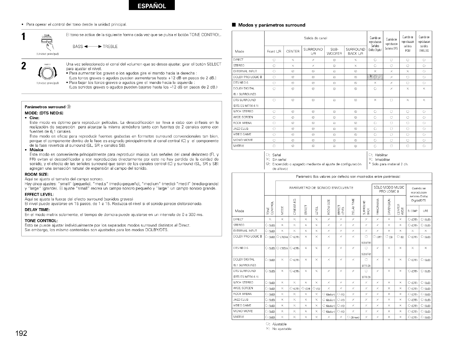
• Para operar el control del tono desde la unidad principal
_ONE El tono se activa de la siguiente forma cada vez que se pulsa el boton TONE CONTROL
COr_OL
BASS HTREBLE
(Ulqdad p ir cipa )
........ Una vez seleccionado el canal del volumen i ue se desea ajustar, girar el boron SELECT
,_O_ " para ajustar el nivel
• Para aumentar los graves o los agudos gre el mando hacia la derecha :
(Los tonos graves o agudos pueden aumentarse hasta +12 dB en pasos de 2 dB)
(Ulqdadpir cipa) • Para baiar los tonos graves o agudos gire el rnando hacia la izquierda :
(Los sonidos graves o agudos pueden baiarse hasta los -12 dB en pasos de 2 dB)
Parametros surround _"
MODE: (DTS NEO:6)
• Cine:
Este modo es 0primo para reprodudr peliculas La descodificaci6n se Ileva a cabo con enfasis en la
realization de separaci6n para alcanzar la misma atm6sfera tanto con fuentes de 2 canales como con
fuentes de 6,1 canales
Este modo es efcaz para reproducil fuentes grabadas en formatos surround convencionales tat] bien,
porque el componente dentro de la fase es asignado principalmente al canal central (C} y el componente
de la fase reverdda al surround (SL, SR y canales SB)
•Mdsica
Este modo es conveniente principahnente para reproducir m_sica Las senales de1 canal delantero (FLy
FR) evitan el descodificador y son reproducidas directamente pot esto no hay perdida de la calidad de
sonido, y el efecto de las senales surround que salen de los canales central (C) y surround (SL, SR y SB)
agregan una sensacion natural de expansion al campo del sonido
ROOM SIZE:
Aqui se aiusta el tamano del campo sonoro
Hay cinco aiustes: "sr_all" (pequeno}, "riled S" (fl]edio-pequeno) r "n_lediuifl '= (_f]edio} "rf]ed I" (medio_grande)
y "large" (grande) El aiuste "small" recrea un campo sonoro pequeno y '1arge" un carnpo sonoro grande
EFFECT LEVEL:
Aqui se ajusta la fuerza del efecto surround /sonidos gravesl
El nivel puede aiustarse en 15 pasos, de 1 a 15 Reduzca el nivel si el sonido parece distorsionado
DELAY TIME:
En el modo matrix solarnente, el tiempo de derhora puede aiustarse en un intervalo de O a 300 ms
TONE CONTROL:
Esto se puede a}ustar individualmente pot los separados modos surround distintos al Direct
Sin embargo, los mismo contenidos son ajustados para los modos DOLBY/DTS
192
•Modos y par&metros surround
Salida de ca/al
SURROUND SUB
Mode Fro/t L/R CENTER L/R WOOFER
DIRECT ( X X ( (
%TEREO ( X X ( (
EXTERNAL INPLT x X
DOLBYPRO O IC II
DTS NEO6 (
DOLBY DIGIT_',L ( _ ( X >
I(6 I SL RROUND) I
DTS SL RROUND ( 1 ( X >
(DTS ES MTRX 6 /)
b/7CH %-ERE© ( _ ( (
WIDE SCREEN ( _ ( (
ROCK A_ Eb,A ( 1 ( (
JAZZ CLLB ( _ ( (
VIDE(} GAME ( _ ( (
M©bX} MOVIE ( _ ( (
MA-RX ( _ ( (
:!':: s[nSe'/alse_'a =_: Ha_j itar
Encend do o apagado ¥_ediallte el auste de conliguraci&n
de altavoz
Parametro (los valores pot defecto son mostrados entre par_/tesisl
Mode
DIRECT X
STERE() ( (0dB
EXTERNAL INPLT ( (0dB
I DOLBY PRO LOGIC ]] I(i (0dBi
DTS NEO6 (i (0dBi
DOLBY DIGITAL (i (0dBi
(6 I SURROUND)
DTS SURROUND (i (0dBi
(DTS ES MTRX 6 /)
_TCH STEREO (i (0dBi
WIDE SCREEN (i (0dBi
ROCK AIS ENA (i (0dBi
JAZZ CLUB (i (0dBi
VIDE(} GAME (i (0dBi
MONO MOVIE (i (0dBi
MATRIX (i (0dBi
Cuandose Cua,_Jcse
Coal@se C.dndos_
reToduzcan eploa_zca) reproduz_an
Scab!es !e_°_uzca_ _aies _al_
SURROUND B_lb_Digi_! %i_iesDTS PCk! _N_LOG
BACK L/R
PARAMETRO DESONIDO ENVOLVENTE SOLOMODOMUSC Ceandose
PROLOGICII reprcduzcafl
setaiesDolby
_ _ _ Digit '/DTS
O _ • G O COrIP LFE
> > X X ((OFF) ( (0dB
> > X X ((OFF) ( (0dB
> > X X > >
( :i_E': ((OFF) X X ( ( OFFi ((3) ( (0/ ((OFF) ( (OdB
_8
( :i_E'S ((OFF) X X ( > >
_8
> ((OFF) X X ( ((OFF) ( (OdB
V-XO
>¢ ( OFF x x (} ( (OFF ( (OdB
V-XO
X X X X ( (OFF ( (OdB
>¢ ( OFF 0 ON) } /0 ( (OFF ( (OdB
>¢ >¢ x x 0 [_u (} (18 ( (OFF ( (OdB
>( >( x x 0 [_u (} (18 ( (OFF ( (OdB
>( >( x x 0 [_u (} (18 ( (OFF ( (OdB
>( >( x x 0 [_u (} (18 ( (OFF ( (OdB
>( >( x x 0 60so} ( (OFF ( (OdB
_: Aiustable
x No aiustable
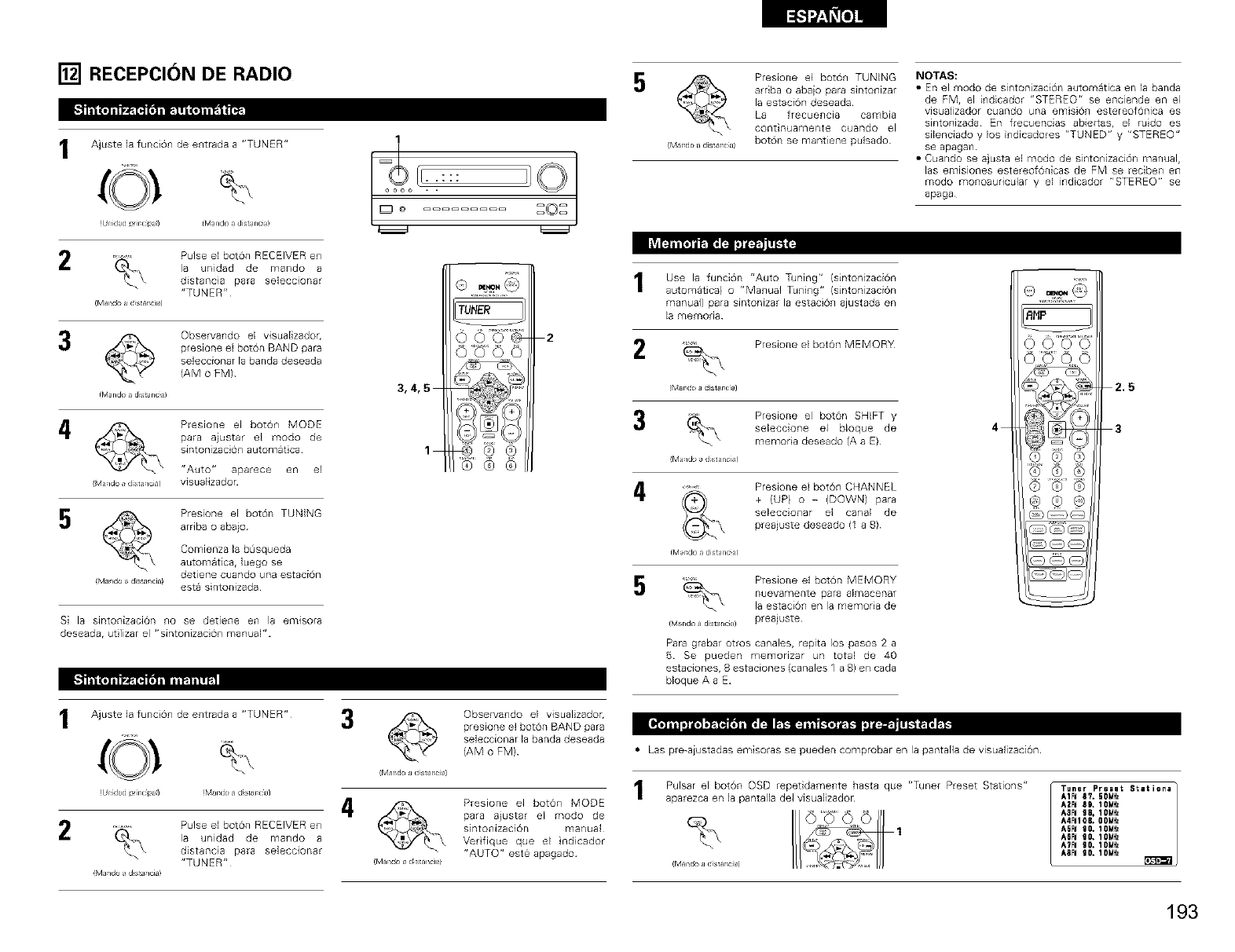
[] RECEPCION DE RADIO
[_ | Is- Jl ._ J|h •
Ajuste la funci6n de entrada a "TUNER"
(©!
(Unidad irclpJ) ([Vlarld/ a dis_ncil)
2
(_,lal_dc_ad_star_cl_)
Pulse el bot6n RECEIVER en
la unidad de mando a
distancia para seleccionar
"TUNER"
_ Observm]do el visualizador,
presione el bot6n BAND para
seleccionar la banda deseada
(AM o FM)
tbland_adistantJ)
4
_Maqdo adist aqciu_
Presione el bot6n MODE
para aiustar el modo de
sintonizaci6n automat ca
"Auto" aparece en el
visualizadon
5
_Maqdo ad_s_aqciu)
Presione el bot6n TUNING
arriba o abajo
Comienza la bOsqueda
automatica, luego se
detiene cuando una estacion
esta sintonizada
Si la sintonizaci0n no se detiene en la emlsora
deseada, ut ]izar el "sintonizaci@] manual"
[_ |II -J| ||,_1 ,|
Ajuste la funcion de entrada a "TUNER"
(Unidad irclpJ) (_,lrdo J dst rcl_)
2Pulse el boron RECEIVER en
la unidad de mando a
distancia para seleccionar
"TUNER"
M J/do ds J/ciu)
1
oaao . .
® *_,__$Q
TUNER
2
3,4,5
1_,@@®®
3
4
©Observando el visualizador,
presione el boron BAND para
seleccionar la banda deseada
(AM o FM)
Presione el bot6n MODE
para a}ustar el modo de
sintolHzaci6rl manual
Verfique que el ndicador
"AUTO" este apagado
Presione el boton TUNING
arriba o abaio para sintonizar
la estacion deseada
La frecuencia cambia
continuamente cuando el
(Mar cjo a dist rca) bot6n se mantiene pulsado
Use la funcion "Auto Tuning" (sintonizaciOn
automatica} o "Manual Tuning" (sintonizaciOn
manual) para sintonizar la estacion ajustada en
la rnemoda
Presione el boton MEMORY
(Mar do a dst r cia)
Presione el boron SHIFT y
seleccione el bloque de
memoria deseado (A a E)
Ma/do a d st anci,,I
4, .......... Presione el boton CHANNEL
_ + (UP) o - (DOWN) para
seleccionar el canal de
preajuste deseado (1 a 8)
(Mar do a distanc a)
Presione el bot6n MEMORY
nuevamente para almacenar
la estacion en la memoria de
preajuste
NOTAS:
•En el modo de sintonizaci6n automatica en la banda
de FM, el indicador "STEREO" se enciende en ei
visualizador cuando una emision estereofOnica es
sintonizada En frecuencias abiertaSr el ruido es
sibnciado y los indicadores "TUNED" y "STEREO"
se apagan
• Cuando se ajusta el modo de sintonizaci6n manual,
las emisiones estereof6nicas de FM se reciben en
modo monoauricular y el indicador "STEREO" se
apaga
_blando a distanc_a)
Par8 grabar ot_os canales, repita lOS paSOS 2 8
5 Se pueden memonzar un total de 40
estacionesr 8 estaciones (canales 1 a B) en cada
bloque A a E
BHP
OQO0
4
0®®
2.5
3
•Lao pre-aiustadas emisoras se pueden comprobar en la pantalla de visualizaci6n
Pulsar el boton OSD repetidame_]te hasta que "Tuner Preset Stations"
aparezca en la pantalla del visualizador
(MUI_J_ a d_star_cla)
Tuner Preset Station=
A1FI 87. 50iHz
A2FI 89, IOMHz
A_FI 98, IOMHz
A4FI108. 00iHz
A6FI 90, IONHz
ATFI gO. IOMHz
A8FI 90. 10MHz
193
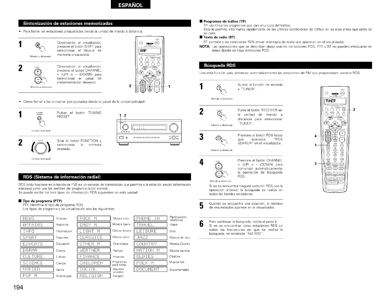
• Para Jlamar las estaciones preajustadas desde la unidad de mando a distancia
1Observando el visualizador,
presione el boton SHIFT para
seleccionar el bloque de
dVland_ dis anci_! memorla preajustada
2........ Observando el visuaEizadob
_.\ preslone el boron CHANNEL
+ (UP) o - (DOWN) para
seleccionar el canal de
presintonizaciOn deseado
(M _rdo J dst r cla)
_m ;]J_."I
2
AHP
1
• Como IEamaralas emisoras pre-ajustadas desde el panel de la unidad principaE
I_,_ Pulsar el boron TUNING
PRESET :::
(Unk_ad pJrclpJ) o ,*
:©:
•Programas de trafico (TP)
TP ide_ltifica los programas que dan anuncios del trafico
Esto le permite i_fformarse rapidame_lte de las Oltimas condicio_les del trafico en su area antes que parta de
SLI casa
• Texto de radio (RT}
RT permite alas estaciones RDS enviar mensajes de texto que aparece;i en el visualizador
NOTA: Las operaciones que se describen abaio usando los botones RDS, PTY y RT no pueden efectuarse en
areas donde no haya emisiones RDS
Use esta funciOn paras ntonizar automaticamente las estaciones de FM que proporcionan servicio RDS
Ajuste la funci6n de entrada
a "TUNER"
iMando a dJsta ncJa!
Pulse el boton RECEIVER en
la unidad de mando a
distanca para seleccionar
"TUNER"
(Mardo a dJst lca)
_O_, Girar el bot6n FUNCTION y 3
selecciorlar la emisora _
deseada
4
(Mal_dO a d[star_cl_)
RDS (s61o funciona en la banda de FM) es un servicio de transmision que permite a la estaci6n enviar informaci6n
adicional }unto con las senales de1 programa radial normaJ
Se puede recibir los tres tipos de informaci6n RDS siguientes en esta unidad:
•Tipo de programa (PTY)
PTY identifica el tipo de programa RDS
Los tipos de programa y su visualizaci@l son los siguientes:
Presione el bot6n RDS hasta
que aparezca "RDS
SEARCHr' en el visualizador
Presione el bot6n CHANNEL
+ (UP) o -(DOWN) para
CO_Tlenzar automaticamente
la operacion de bSsqueda
RDS
(Mrdo adistant_)
S no se encuentra ninguna estacion RDS con la
operacion anterior, la bL_squeda se realiza en
todas las bandas receploras
Cuando se encuentra una estaciOn, el hombre
de esa estaci6n aparece en el visualizador
Para continuar la bL_squeda, repita el paso 4
Si no se encuentran otras estaciones RDS en
todas las frecuencias en que se realizo la
bOsqueda, se enciende "NO RDS"
i
TUNER
000_
o 6
4
1 _,©®
3
2
[ }}[:]:i,iil]i; ] Noticias I [;i:OCi::: i'i
[ i:::_i:;'[:;i:::_][i:_:il]i; ] Aegocios I[][:i;:E][ii',' i'i
[ ii',F:O ] hlo_r_'ac_,_IL ]:aiiiHi i'i
[ il]i;i:'OR T ] Deportes I Ci.i:iil]i;::]]; ): CII]I;
[ [][:i::)iiCi::i['[][: ] Educac6n IO]'H[][:R i'i
[ [:)RF:Ii'}I::I ] Drama Ihi[[F::Ni ii:i:F;:
[ ] Cultura I i: ]: i_:i:_i iCE
[ II]I;C]:Ei iCE ] CJenca I Cii]:[ i])REH
[i Ii::i[;:]:[][[) ] Vaios I:i[ihi:H[:::[[:ii ....
[ _::'OP i'i ] M_isica pop Ii:[:[]][[ ]i[_i]i[[ [:[:_i}
M_isica ock I[::'iK::il}[][ ][}}
MOsicaIgera I "i[;i:F:iilEi ....
Cl_sico Ivarlo I[i;][][:]][;UR[[[
Cl_s[co seio I:}@_[:'[]['
Otra mOsica I COiill!'i:_:','
_empo I iIF:gi :[Oi', i'l
Fhlanzas I Oi. D ]: []::i;];
Progr_mas I i:O[ i(: i'i
paa ninos
Asuntos I [)0 C} ii'ii[i:P:i
socia]es
Religion
Parflc[paci6n
te ef6n[ca
Vaes
Ocio
MSsica de azz
M@sica Country
MOsica national
CI_s[cos
M_Is[ca fo_
Docu ¥1enta]es
194
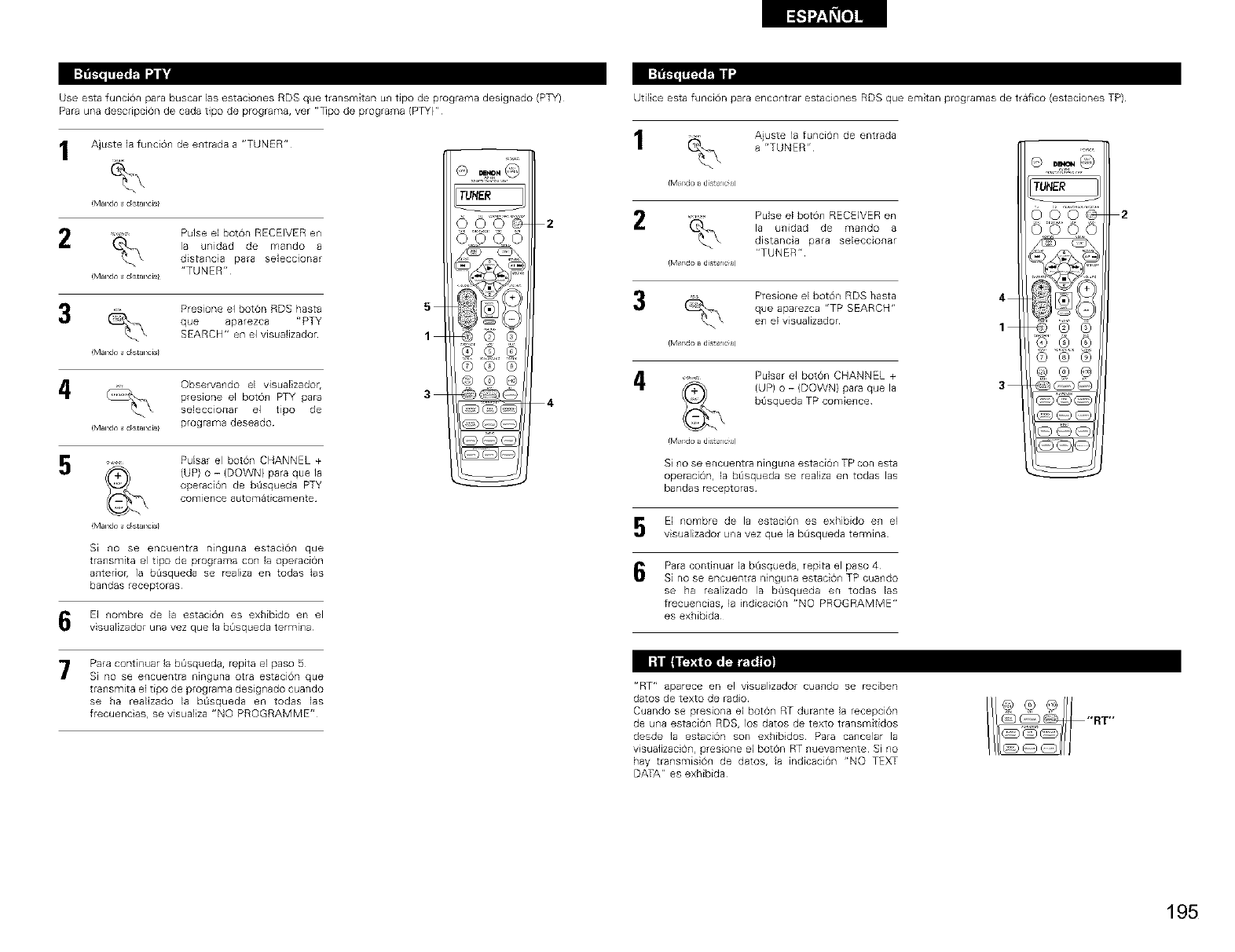
_[,,_]:!_'lll_m I":'li'd
Use esta funciOn para buscar las estaciones RDS que transmitan un tipo de programa designado (PTY) Utilice esta funciOn para encontrar estaciones RDS que emitan programas de trafico (estaciones TP)
Para una descripciOn de cada tipo de programa, ver "Tpo de programa (PTY}"
Ajuste Jafunci6n de entrada a "TUNER"
!Mal_ a d_Stal_ci_
....... Pulse el boron RECEIVER en
la unidad de mando a
distancia para seleccionar
"TUNER"
(Mal_do a d st _l_ci_l
Presione el boton RDS hasta
que aparezca "PTY
SEARCH" en el visualizador
(Mal_do a d st _l_ci_l
5
1
4Observando el visualizador,
preslone el boton PTY para 3
seleccionar el tipo de
(Mal_dO a dst ii_ci_l programa deseado
Pulsar el bot6n CHANNEL +
(UP) o - (DOWN} para que la
operadOn de b_isqueda PTY
comlence autoFlaticamente
(Mal_do a d st _l_ci_l
Si no se encuentra ninguna estaciOn que
transmita el tipo de programa con la operaci6n
anterioc la b_squeda se realiza en todas Jas
bandas receptoras
G El nombre de la estad6n es exhibido en el
visualizadoruna vez que lab_isquedatermina
Para continuarlabOsqueda, repitaelpaso S
Si no se erlcuentranlngurlaotra estaci6tlque
transmitaeltipode programa designado cuando
se ha realizadola b_squeda en todas las
frecuencias,se visualiza"NO PROGRAMME"
TUNER
©®@
@@
@@@
22
Ajuste la funci6n de entrada
a "TUNER"
Mar_dc> a dist_lc_a)
Pulse elboton RECEIVER en
la unidad de mando a
distancia para seleccionar
"TUNER"
Mar_dc> a dist_da)
Presione el bot6n RDS hasta
que aparezca "TP SEARCH"
en el visualizador
Iv1 r do a disi K: ])
Mando a dist_K:_a)
4
4
Pulsar el boton CHANNEL +
(UP) o - (DOWN} para que la
b_isqueda TP comience
Sino se encuentra ninguna estaci6n TP con @sta
operacion, la bOsqueda se realiza en todas las
bandas receptoras
El nombre de la estaci6n es exhibido en el
visualizador una vez que JabOsqueda termina
Para continuar la bL_squeda, repita el paso 4
Si no se encuentra nlnguna estacion TP cuarldQ
se ha realizado la b_isqueda en todas las
frecuencias, la indicaci6n "NO PROGRAMME"
es exhibida
TUNER
4
_,_
2
"RT" aparece en el visualizador cuando se reciben
datos de texto de radio
Cuando se presiona el boton RT durante la recepcion
de una estaciOn RDS, los datos de texto transmitidos
desde la estaci6n son exhibdos Para cancelar la
visualizaci6n, presione el boton RT nuevamente Si no
hay transmision de datos, la indicaciOn "NO TEXT
DATA" es exhibida
195
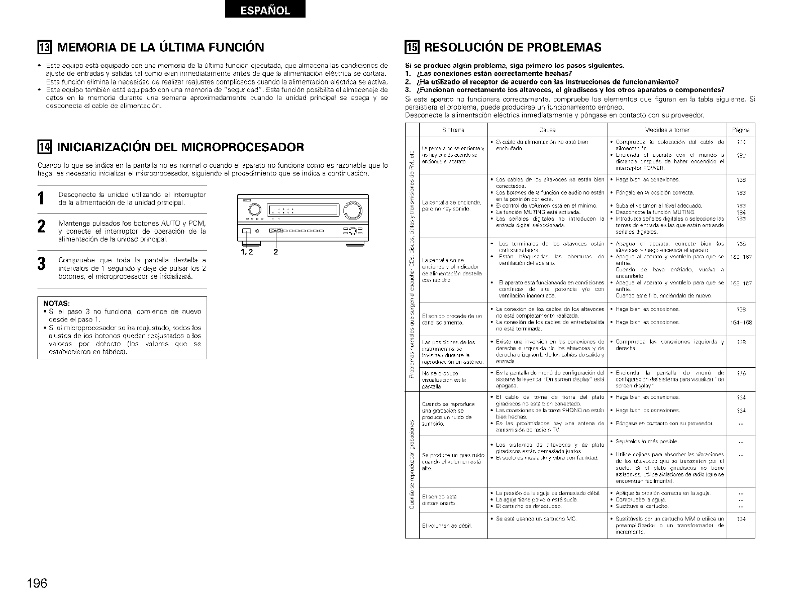
[] MEMORIA DE LA ULTIMA FUNCION
• Este equipo esta equipado con una memoria de la Oltima funci6n ejecutadar que almacena las condiciones de
ajuste de entradas y saEidas taE como eran inmediatamente antes de que la alimentaci6n electrica se cortara
Esta funci6n elimina la necesidad de realizar reajustes complicados cuando la alimentaci6n electrica se activa
• Este equipo tambian esta equipado con una memoria de "seguddad" Esta funci6n posibilita el almacenaie de
datos en la memona durante una semana aproximadamente cuando la unidad principaE se apaga y se
desconecta el cable de aEimentaci6n
[] INICIARIZACION DEL MICROPROCESADOR
Cuando Io que se ndca en la pantalla no es normal o cuando el aparato no funciona como es razonable que Io
hags, es necesar o inicializar el microprocesadoc siguiendo el procedimiento que se indica a continuaci6n
Desconecte la unidad utilizando el interruptor
de la alimentacion de la unidad principal
2 Mantenga pulsados los botones AUTO y PCM,
y conecte el nterruptor de operaci6n de la
alimentaci6n de la unidad pr ncipal
3Compruebe que toda la pantalla destella a
intervalos de 1 segundo y deje de pulsar los 2
botones, el microprocesador se inicializara
NOTAS:
• Si el paso 3no funciona, coml@nce de l]uevo
desde el paso 1
• Si el microprocesador se ha reajustado, todos los
ajustes de los botones quedan reaiustados a los
valores por defecto (los valores que se
establecieron en fabrical
1,2 2
[] RESOLUCION DE PROBLEMAS
Si se produce algdn problema, siga pdmero los pasos siguientes,
1. _Las conexiones estan correctamente hechas?
2. _Ha utilizado el receptor de acuerdo con las instrucciones de funcionamiento?
3. _Funcionan correctamente los altavoces, el giradiscos y los otros aparatos o componentes?
Si este aparato no funcionara correctamente, corr_pruebe los elementos que figuran en la tabla siguiente Si
persistiera el problems, puede producirse un funcionamiento err6neo
Desconecte la alimentacion el6ctrica inmediatamente y pongase en contacto con su proveedor
Sir/t o ¥_a Causa Medidas a tor,/ar P_gna
• El cable de almentaci6n no es[a bel • Cor/pruebe s colocsciOn del cable de /64
dLa panta!b i_o se enciel_t e v e_chu fado alimentaci6n
¥ nol_aysol_doc_andose • E_cienda el sparslo con el mando s /82
el_ciende elaparato dislancia despu(_s de babel encendido el
interl/iptor POWER
• Haga bJen Iss conexiones
®
2
La pantalls se enciende
peso no hay sonido
La pantalls _o se
enciende y el indicador
de alimel laci6n deslella
con lapiclez
•Los csbes de os allavoces _o estan bien
coneclados
•Los helot es tie a fune 6n de auclio no estan
e_ la posici6n cer_eola
• E_ control de vo um_-_ esta en _4m[Hr_o
• La ulei6_ MUTING esta aclvada
• as set'ales d_itsles no inlroclueen la
el lrsda digital se ecc o_ada
• p6ngalo en a posici6n correcla
• Subs el volumen al nvel adecuado
• Desconecte la funci6n MUTING
• Introduzca senales digitales o seleccione las
tomas de entrads _-_las que eslan enua_do
seCales cli_ilales
I • Los telminales tie los allavoces estan I • Apsgue el apaato conecte ben os
altavoees y luego encienda el apa_alo
• Estan bloqueadss las aberlulss de • Apa_ue el apa4ato y vent[lelo para que se
vent ilaci6n del apalalo enfrie
Cusndo se hays enf_iado vuelvs s
encende_lo
• El apara_o esta fu_cio_ando en con_liciones • Apa_ue el apa4ato y vent[lelo para que se
conl[n_as de siva polenc_s y/o con enfrie
I ventilaci6n inailecuada I Cuando este flio enciendslo ile nuevo
• La conexi6n de los cables tie los al_avoces
no esla competamen_e realzacla
• La conexi6n de los cables de e_ usds/sa icla
no esl_ telm nada
• Haga bJen las conexiones
• Haga bJen Iss conexiones
/68
/83
/83
/83
/68
163167
163167
El sondo precede tie ur
canal solamente
$
Las 9osicones de los •Exisle una inversi6n en as conexiones tie • Compruebe las co exlones izquie_cls y 68
• nslrumentos se derecha e zquieldS tie os allavoces y tie delecha
nvie_len durance la derecha e izqu erda de los cabes tie salicla
ep od( cci6n en esleleo e_slrsda
o
r_ No se produce • Eis Is 9snlalla de r/e¢,O tie confi_uraciOn del • Elscienda la psnlalla tie menu de 75
visual zaci6n e_s Is sister sa a leye_sda 'On screen disp ay ' esta conf g_raci6n del sistema pars visua izaa on
3al/lalla aDsgada screen clisglay '
• El cable de toma de tielra del 91ate • Haga bien las conexiones 64
C _anclo se lepaoduce g_radiscos no esta Bien coneclsdo
na grsbaci6n se • Las conexiones de la lonqa PHONO no eslan • Haga bJen los conexiones 64
3roduce url rudo de ben hechas
$ zumbJdo • E_S las 9roximdades hay ma sntena tie • Pon_ase e_s contac_o con su poveedo_
lrsnsmJsi6n de rado o TV
• LOS sstemas de altavoces y de 9late • Segs/elos omasposible
g_radiscos es_s demssado juntos • Udlice coines pars sbso her 1as vibrscones
Se prod(ice un g_al/ luido • E suelo es nestable y vibrs con faciiclad
cuando el volumen esta de los a _avoees que se [la_ssr illen [}o_ el
alto suelo Si el plato giradscos no tielse
a slado es ul Jice aislaclores de rsdo Ique se
enc_ e_lran _cilment e)
o • La p esi6_ de la aguia ms demasisdo debi • Apic_ue a p esi6n correcla en la agu_a
• El sondo esta • La agu}a tiene polvo o esta suca • Colnpluebe la agu}a
dislo sionado • E csf_ucho es defec_uoso • Sust _uya el cartuclo
• Se es_6 ussndo u_ cartucho MC • Sus_ _uya_o pot u_ ca_tucho MM o utiice u_ /64
EIvolumenesdelJi_ pleamplifcsdol o un transfolmsdor de
incremento
/68
164_168
196
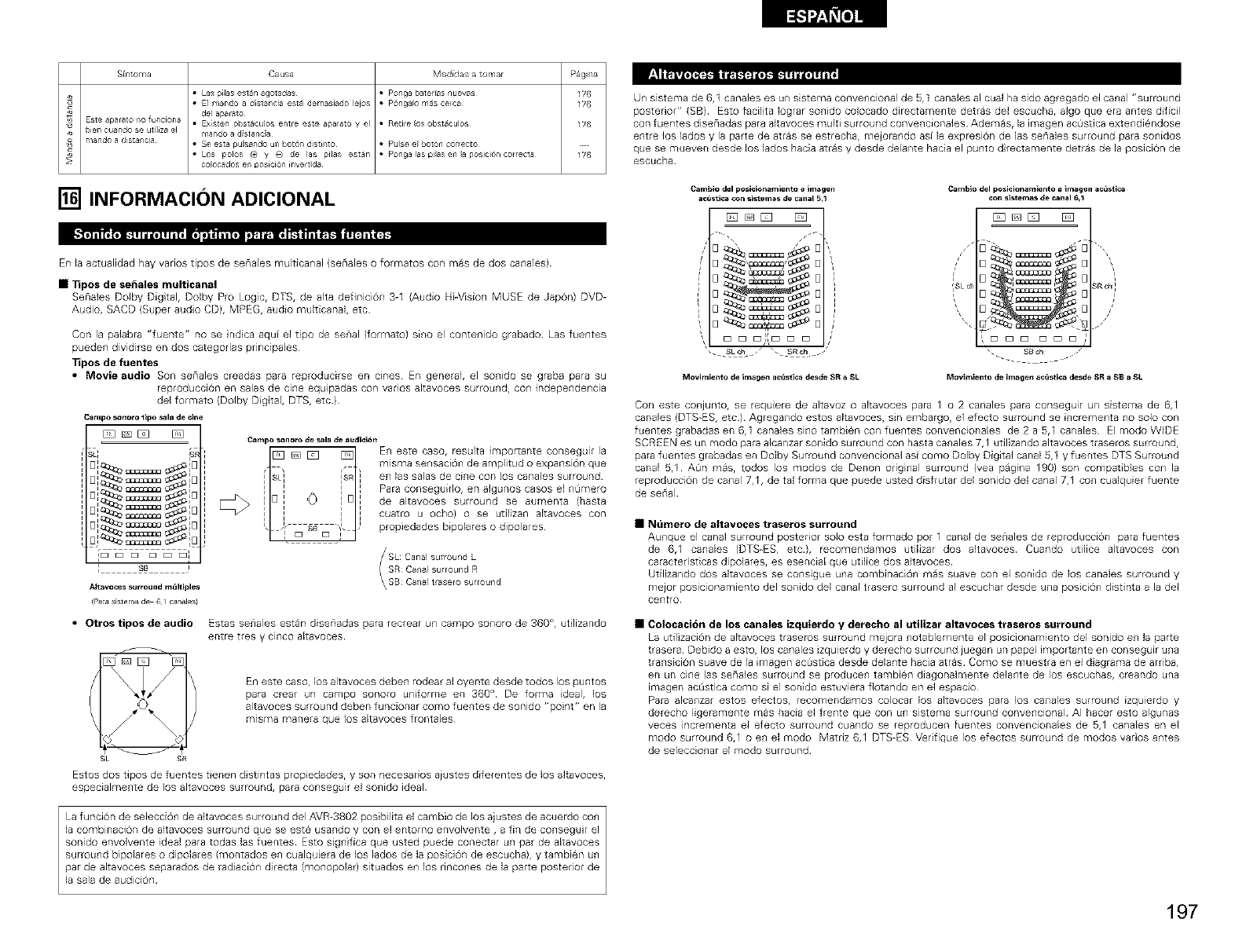
Sfrltoma Causa Medidas a tor,/ar P_gi/a
• Las _ilas esian agotadas • Ponga baler[as nuevas 176
• El rnando a dislancia esta demasiado lejo5 • pOngalo mas Celca 176
del aparslo
Este apa_ato _o lunciona o Existen obs_aculos enire este aparato y el • Retire los obsiaculos 176
_ien cuando se uti]iza el rna_do a dist ancia
mando a clista_cia o Se es_ pulsando un boron dis_in_o • p_Jlse el bot(_n cor_ecto
• Lo5 polos (9 y q9 de la5 pilas est_n • Ponga las pilas en la po_lcid_n correcla 176
colocados e_ position inverTida
[] INFORMACION ADICIONAL
__I_ i_ r_T_I _T_I
En la actualidad hay varios tipos de senales mul6canal (seriales o formatos con mas de dos canales)
• Tipos de se_ales multicanal
Senales Dolby Digtal, Doby Pro Logic, DTS, de alta de6nici6n 3-1 (Audio Hi-Vision MUSE de Jap6n) DVD-
Audio, SACD (Super audio CD), MPEG, audio mukicanal, etc
Con la palabra "fuente" no se ndca aqui el tipo de senal {formato) sino el contenido grabado Las fuentes
pueden dividirse en dos categodas prlnclpales
Tipos de fuentes
•Movie audio Son seriales creadas para reproducirse en cines En general, el sonido se graba para su
repfoducciOn en salas de cine equpadas con varios altavoces surround, con independencia
del formato {Dolby DigitaE, DTS, etc}
Campo son_o tipo _ala de cine
31 Ig
2, _e_ susuuuuu_ I[3
3,_ _,[3
SB =
Campo sonoro de sala de a udi_ib_
misma sensaciOn de amplitud o expansion que
I SLI IsR I en las salas de cine con los canales surround
iI ,I iI ,I Para conseguirlo, en algunos casos el nL_mero
[_ I i i i
,[3 , _ ,[3 ,de alLavoces surround se aumenta (hasta
,,,, cuatro u ocho) o se utilizan altavoces con
k _,'[ sB "), )propiedades bipolares o dipolares
i [3 [3 i
AItavoaes surround multi_les
(Para sistema de 61 canales/
•Otros tipos de audio
-C/ok
SL S_
Estas senales estan disenadas para recrear un campo sonoro de 360 °, ut lizando
entre tfes y Ginco altavoces
En este caso, los altavoces deben rodear al oyente desde todos los puntos
para crear un campo sonoro uniforme en 360 ° De forma ideal, los
alLavoces surround deben funcionar como fuentes de sonido "point" en la
mlsma manera que los altavoces frontales
Estos dos 6pos de fuentes 6enen d stintas propiedades, y son necesados aiustes diferentes de los altavoces,
especialmente de los altavoces surround, para conseguir el sonido ideal
Un sistema de 6,1 canales es un sistema convencional de 5r1 canales al cual ha sido agregado el canal "surround
posterior" (SB) Esto facilita Iograr sonido colocado directamente detras del escucha, algo que era antes dficil
con fuentes disenadas para altavoces multi surround convencionales Ademas, la imagen acOstica extendiendose
entre los lados y la parte de arras se estrecha, mejorando asi la expresion de las senales surround para sonidos
que se mueven desde los lados hacia arras y desde delante hacia el punto directamente detras de la posicion de
escucha
Cam_io del p_i_ion_mient_ e imagen
ac_ti_a _on si_temas de canal
[]_E3 []
Mevimiento de imagen ac_ti_a des_e SR a SL
Cambio del p_i_ion_miente e ima _nacu_ti_a
_on _istemas de ca_al
[3 [3 E3 [3 E3 [3
SB ch /
Movimie_te _e image_ a_u_ti_a de.de SR aSB aSL
Con este conjunto, se requiere de altavoz o altavoces para 1 o 2 canales para consegulr un sistema de 6,1
canales (DTS-ES, etc) Agregando estos akavoces, sin embargo, el efecto surround se incrementa no solo con
fuentes grabadas en 6,1 canabs sino tambien con fuentes convenc_onales de 2 a 5,I canales El modo WIDE
SCREEN es un modo para alcanzar sonido surround con hasta canales 7,1 u61izando altavoces traseros surround,
para fuentes grabadas en Dolby Surround convencional asi como Doby Digital canal 5,1 y fuentes DTS Surround
canal 5,1 AQn mas, todos los modos de Denon original surround (yea pagina 19g) son compatibles con la
reproduccion de canal 7,1, de tal forma que puede usted disffutar del sonido del canal 7,1 con cualquier fuente
de sepal
•Numero de altavoces traseros surround
Aunque el canal surround posterior solo esta formado pot 1 canal de senales de reproduccion para fuentes
de 6,1 canales (DTS-ES, etc), recomendamos utilizar dos altavoces Cuando utilice altavoces con
caracteristicas dipolares, es esencial que utilice dos altavoces
Utilizando dos altavoces se consigue una combinaciOn mas suave con el sonido de los canabs surround y
mejor posicionamiento del sonido del canal trasero surround al escuchar desde una posiciOn distinta a la del
centfo
•Colocacion de los canales izquierdo y derecho al utilizar altavoces traseros surround
La utilizaci0r_ de altavoces %raseros surround mejora notablemente el posidonamierxo del sonido en h parte
trasera Debido a esto, los ¢anales izquierdo y derecho surround juegan un pape] importarxe en ¢onsegu=r una
transicion suave de la ilnagen acOstica desde delante hacia arras Co[no se muestra en el d agrama de arriba,
en un cine las senales surround se producen tambien diagonalmente delante de los escuchas, creando una
imagen a@stica como si el sonido estuviera fiotando en el espac;o
Para alcanzar estos efectos, recomendamos GOlocar los altavoces para los canales surround izquierdo y
derecho ligeramente mas hacia el frente que con un slstema surround convencional AI hacer esto algunas
veces ir_crelnenta el efecto surround cuando se reproduceR fuentes convencionales de 5,1 canales en el
modo surround 6,1 o en el modo Matriz 6,1 DTS-ES V_dfique los efectos surround de modos vados antes
de seleccionar el modo surround
la sala de audicion
197
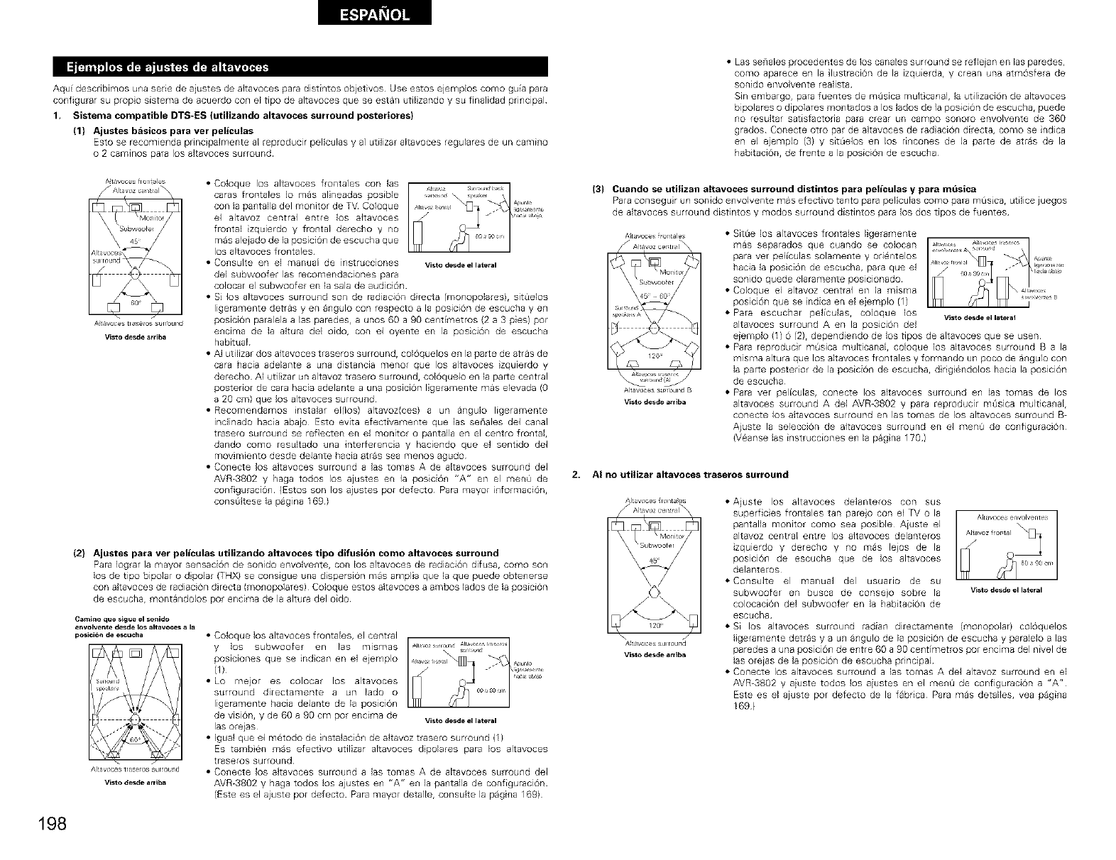
Aqui describimos una sede de aiustes de aitavoces para distintos objetivos Use estos ejemplos como gu_a para
configurar su propo sistems de acuerdo co_ el tipo de altavoces que se estan utilizando y su finalidad principal
1. Sistema compatible DTS-ES (utilizando altavoces surround posteriores}
(1) Ajustes basicos para ver peliculas
Esto se recomie_da principalmente al reproducir peliculas y al utilizar altavoces regulares de un cami_o
O 2 camfflos para los sltavoces surround
• Las senales procedentes de lOS canales surround se refleia n en las paredes,
como aparece en la lustracion de la izquierda, y crean una atmOsfera de
sonido envolvente realista
Sin embargo, pars fuentes de mtisica mult canair la utilizaciOn de altavoces
bipolares o dipolares montados a los lados de ]a posiciOn de escucha, puede
no resultar satisfactoria pars crear un campo sono[o envolvente de 360
grados Conecte otto par de akavoces de tad aciOn directs, como se indica
en el ejemplo (3) y SitL_elos en los nncones de la parte de arras de la
habitacion, de frente a la posiciOn de escucha
A_tavoces flontales
A_tavoces tl_seros s_rr_ul_d
Visto desde ardba
• Coloque los allavoces frontales con las
caras frontales Io mas alineadas posible
con la pantalla del monitor de TV Coloque
el altavoz central entre los altavoces
frontal izquierdo y frontal derecho y no
mas alejado de la posiciOn de escucha que
los altavoces frontales
• Consulte en el manual de instrucciones
del subwoofer las recomendaciones para
Visto desde el lateral
colocar el subwoofer en la sala de audicion
• Si los altavoces surround son de radiacion directs (monopolares), sitQelos
ligeramente detras yen angulo con respecto a la posici6n de escucba yen
poslcion paralela alas paredes, a unos 60 a 90 centimetros (2 a 3 pies) pot
enclma de is altura del oido, con el oyente en la posici6n de escucha
habitual
• AI utilizar dos altavoces traseros surround, colOquelos en la parte de atras de
cars hacia adelante a una distancia menor que los altavoces zquierdo y
derecho AI utilizar un altavoz trasero surround, colOquelo en la parte central
posterior de cars hacia adelante a una poslciOn ligeramente mas elevada (O
a 20 cm) que los altavoces surround
• Recomendamos instalar el(los) altavoz(ces) aun angulo ligeramente
inclinado hacia abajo Esto evita efectivamente que las senales del canal
trasero surround se refiecten en el monitor o pantaHa en el centro frontal,
dando como resultado una inter[erencia y haciendo que el sentdo de1
movimlento desde delante hacia arras sea menos agudo
• Conecte los altavoces surround a las tomas A de altavoces surround del
AVR-3902 y bags todos los ajustes en ]a posiciOn "A" en el menQ de
configuraciOn (Estos son los aiustes pot defecto Para mayor informaci6n,
consGItese la pagina 169)
(2) Ajustes para vet peliculas utilizando altavoces tipo difusion como altavoces surround
Para Iograr la mayor sensaci6n de sonido envolve_lte, con los altavoces de radiaci6n difusa, como sol1
los de tipo bipolar o dipolar (THX} se consigue una dispersi6n mas amplia que Is que puede obtenerse
con altavoces de radiaciOn directa (monopolares) Coloque estos altavoces a ambos lados de la posicion
de escucba, montandolos pot encims de la altura del oido
€amino que sigue el _nido
envolvente desde lOS altav_es a la
pesici6n de escu_i]a
Al_av_es traseros sulround
Visto des_e a rril_a
• Coloque los altavoces frontales, el central
y los subwoofer en las mlsmas
poslclones que se indcan en el ejemplo
(1)
• Lo mejor es colocar los altavoces
surround directamente a un lado o
ligeramente hacia delante de la posicion
de vision, y de 60 a 90 cm pot encima de vistodesde ellateral
las orejas
• Igual que el metodo de instalaciOn de akavoz trasero surround (1)
Es tarnbien rnas efectvo utilizar altavoces dipolares para los altavoces
traseros surround
• Conecte los akavoces surround a ]as tomas A de akavoces surround del
AVR-3902 y haga todos los ajustes en "A" en la pantalla de configuracion
(Este es el ajuste pot defecto Para mayor detaile, consulte la pagina 169)
(3} Cuando se utilizan attavoces surround distintos para peliculas y para mdsica
Para conseguir un sonido e_wolvente mas efectivo tanto para peliculas como pars [r]usl_ rutilice juegos
de sltavoces surround distintos y modos surround distintos pars los dos tipos de fuentes
Air avoces fror_tales
/" A_tavoz cer_tlal
120 _
AIt avoc_s surround B
Vist_ des_e a_riba
• SitL_e lOS altavoces frontales ligeramente
ass separados que cuando se colocan
pars vet pel_culas solamente y orientelos
hacia la posici6n de escucha, pars que el
sonido quede claramente posicionado
• Coloque el altavoz central en la misma
posici6n que se ndica en el ejemplo (1)
• Pars escuchar pel_culas, coloque los •dis_ desdeel I_teral
al[avoces surround A en la posici6n del
e}emplo (1) 6 (2), depend endo de los tipos de altavoces que se usen
•Para reproducir mOsica multicanal, coloque los altavoces surround B a la
misma altura que los altavoces frontales y formando un poco de angulo con
la parte posterior de la posiciOn de escucha, d rig endolos hacia la posici6n
de escucba
•Para vet peliculas, conecte los altavoces surround en las tomss de los
altavoces surround A del AVR-3802 y pars reproducir mtisica mul[icanal,
conecte los altavoces surround en las tomas de los altavoces surround B-
Aiuste la seleccion de altavoces surround en el merit1 de conflguraciOn
(Veanse las instrucciones en la pagna 170)
2. AI no utilizar altavoces traseros surround
Al_av_es _ront a_es
V_st_ des_e a_ba
• Ajuste los altavoces delanteros con sus
superficies frontales tan pare)o con el TV o la
pantalla monitor como sea posible Aiuste el
allavoz central erltre los altavoces delanteros
izquierdo y derecho y no mas leios de la
poslci6n de escucha que de los altavoces
delante_os
• Consulte el manual del usuario de su
subwoofel en busca de conselo sobre la Visl_des_eell_teral
colocaciOn del subwoofer en is habitacion de
escucha
• Si los altavoces surround radian directamente (monopolar) colOquelos
ligeramente detras y aun angulo de la posicion de escucha y paralelo alas
paredes a una posicion de entre 60 a 90 centimetros por encima del nivel de
las oreias de la posicion de escucha principal
• Conecte los altavoces surround alas tomas A del altavoz surround en el
AVR-3802 y aiuste todos los aiustes en el menQ de configuracion a "A"
Este es el ajuste por defecto de la fabdca Para mas detalles, yea pagans
169)
198
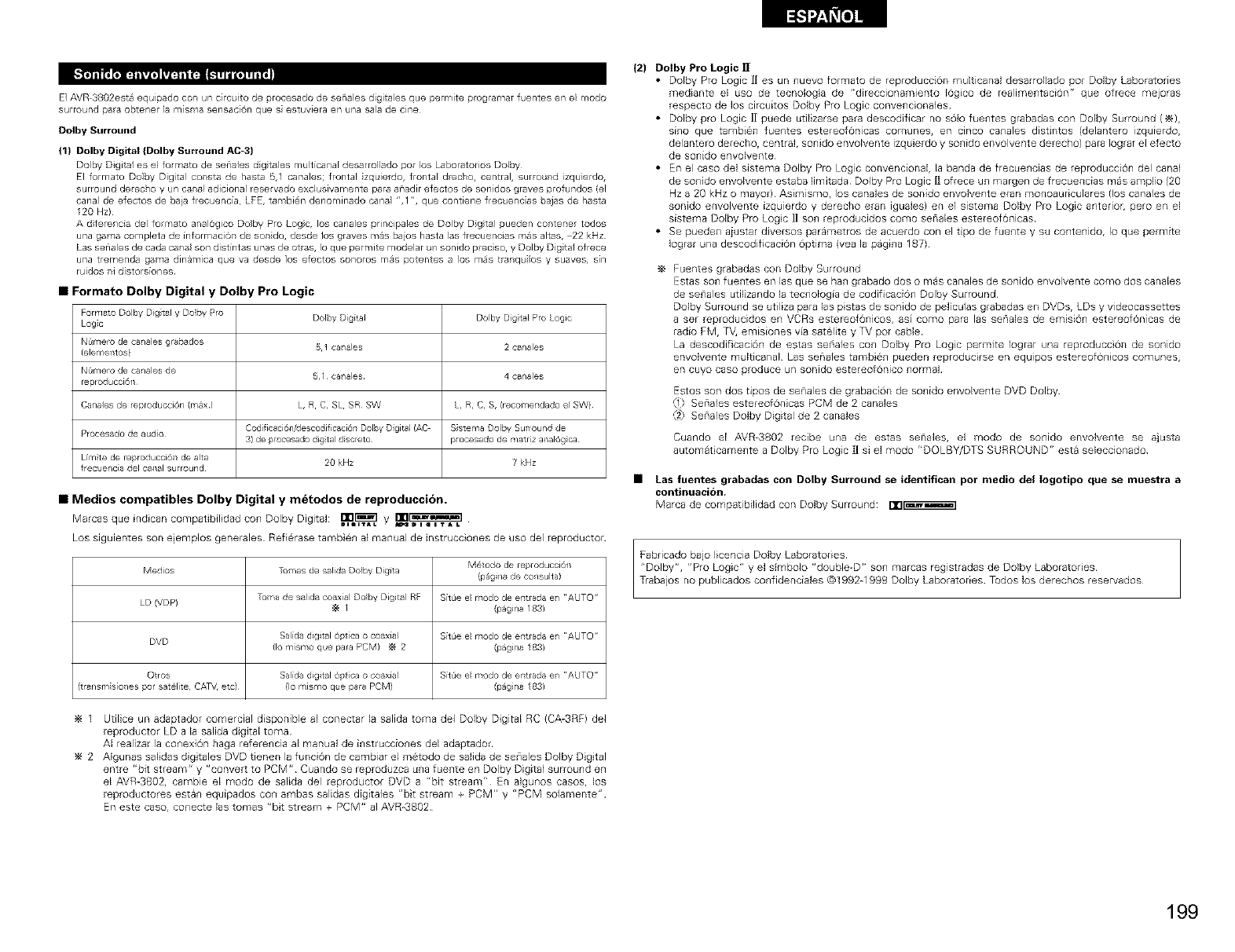
El AVR 3802est_ equipado con un circuito de isrocesado de senales digitales que permlte programar fuentes en el modo
surround pa(a obtener la msma sensaci6n que s estuviera en una sala de cine
Dolby Surround
(1) Dolby Digital (Dolby Surround AC-3)
Dolby Digital es el formato de senales d gta es multicanal desarrollado isor los Laboratorios Dolby
El formato Do]by Digital co_sta de hasta 5,1 canales; frontal izquierdo, frontal drecho, central, surround izquierdo,
surround derec}so y un canal adicional reservado exclusivamente para anadir efectos de sonidos graves profundos (el
canal de efectos de baja frecuencia, LFE, tambi_n denominado canal ",1 ", que contiene frecuencias bajas de hasta
I20 Hz)
A diferencia del formato anal6gico Dolby Pro Logic, los canales principales de Dolby Digital isueden co,tenet todos
una gama completa de [nformaciO_ de so_ido, desde los graves rn_s bajos hasta }as frecuencias m_s altas, 22 kHz
Las senales de cada canal son d[st[ntas unas de otras, Io {sue perrnite modelar u_ sonido preciso, y Dolby Digit al ofrece
una tremenda gama din_mica que va desde los efectos sonoros m_s potentes a los m_s tra_quilos y suaves, sin
ruidos _i d[stors[ones
Formato Dolby Digital y Dolby Pro Logic
Forr'latO Dolby Dig tal y Dolr_y Pro Dolr_y Digital Dolby Dgtal Pro Logic
Logo
NOr'lero de ca/ales grabados
(eJemet_tos} 51 ca/ales 2 canales
NOr'lero de canales de
reproducci6n 5,1 ca/ales 4 canales
Canales de reproducci6n (r,/ax) L, R C, SL SR SW L, R, C, S, (recomeTldado e SW}
Procesado de audio Codificaci6n/descodificaci6n Dolby Digital (AC S stenla Dolby Surround de
3) de plocesado digital d_screto procesado de r,/atfiz analog ca
Lfrn te de reproducci6T1 de alta 20 kHz 7 kHz
frecuenc a del canal surround
•Medios compatibles Dolby Digital y metodos de reproducci6n.
Marcas que indican corr_patibilidad con Dolby Digital: =B3=,[:_._y r_
A_IDIQITAL
Los siguientes son ejemplos generales Refierase tarnb 6_1al manual de instruccio_les de uso del reproductor
M_todo de reproduccJ6T1
Medios To ¥_asde salida Dolby Digit a (p_gi/a de co/sulta}
LD (VDPI To¥_a de salida coaxial Doby Digita RF S[tde e modo de eTltrada e/ AUTO"
I (pagi/a 1831
DVD Sa[da digital Opt[ca o coaxial S[tde e modo de eTltrada e/ AUTO"
(Iom[smoquepara PCM) _ 2 (pagi/a 1831
Otros Sa[da digital Opt[ca o coax[a S[tde e modo de eTltrada e/ AUTO"
(transm sio/es pot satOlite, CAW, etc) (Io mismo que para PCM) (pagi/a 1831
1 Utilice un adaptador comercial disponible al conectar la salida toma de1 Dolby Digital RC (CA-3RF) del
reproductor LD a la salida digital toma
AI realizar la conexiOn haga referencia al manual de instrucciones del adaptador
2 Algunas salidas dig tales DVD tienen la funcion de cambiar el metodo de salida de senales Dolby Digtal
entre "bit stream" y "convert to PCM" Cuando se reproduzca una fuente en Dolby Digital surround en
el AVR-3g02, cambie el modo de salida del reproductor DVD a "bit stream" En algunos casos, los
reproductores estan equipados con ambas salidas digitales "bit stream + PCM" y "PCM solamente"
En este caso, conecte las tomas "bt stream + PCM" al AVR-3802
(2) Dolby Pro Logic ]1
•Dolby Pro Logic ][ es un nuevo formato de reproducciOn multicanal desarrollado pot Do;by Laboratories
mediante el uso de tecno;oga de "direccionamiento 16gico de realimentacion" que ofrece mejoras
respecto de los circuitos Dolby Pro Logic convencionales
• Dolby pro Logic ]1 puede utilizarse para descodificar no sOlo fuentes grabadas con Dolbv Surround (_),
sino que tambien fuentes estereofOnicas comunes, en cinco canales distintos (delantero izquierdo,
delanteEo derecho, central, sonido envolvente izquierdo y sonido envolvente derecho) para Iograr el efecto
de sonido envolvente
• En el caso del sistema Dolby Pro Logic convencional, la banda de frecuencias de reproducciOn del canal
de sonido envolvente estaba fimitada Dolby Pro Logic [l ofrece un margen de frecuencias mas ampfio (20
Hz a 20 kHz o mayor) Asimismo, los canales de sonido envolvente eran monoauriculares (los canales de
sonido envolvente izquierdo y derecho eran iguales) en el sistema Dolby Pro Logic anterior, pero en el
sistema Dolby Pro Logc 1] son reproducidos como senales estereofonicas
• Se pueden aiustar diversos parametros de acuerdo con el tipo de fuente y su contenido, Io que permite
Jograr una descodificacion Optima (yea la pagina 1871
Fuentes grabadas con Dolby Surround
Estas son fuentes en las que se Ban grabado dos o mas canales de sonido envolvente como dos canales
de senales utilizando la tecnologFa de codificacion Dolby Surround
Dolby Surround se utiliza para las pistas de sonido de peficulas grabadas en DVDs, LDs y videocassettes
a ser reproducidos en VCRs estereofonicos, asf como para las senales de emisi6n estereofonicas de
radio FM, T_ emisiones via satelite y TV pot cable
La descodificaci6n de estas seriales con Dolby Pro Logic permite Iograr una reproducci6n de sonido
envolvente multicanal has senales tambien pueden reproducirse en equlpos estereofonicos comunes,
en cuyo caso produce un sonido estereof6nico normal
Estos son dos tipos de se_lales de grabaci6n de sonido envolvente DVD Dolby
,1 Sena es estereof6nicas PCM de 2 canales
,2,= Sena es Dolby Digital de 2 canales
Cuando el AVR-3802 recibe una de estas senales, el modo de sonido envolvente se ajusta
automat camente a Dolby Pro Logic H si el modo "DOLBY/DTS SURROUND" esta seleccionado
•Las fuentes grabadas con Dolby Surround se identiflcan por medio del Iogotipo que se muestra a
continuacibn,
Marca de compatibilidad con Dolby Surround: nn_]
Fabricado bajo licencia Dolby Laboratories
"Dolby", "Pro Logic" y el slmbolo "double-D" son marcas registradas de Dolby Laboratories
Trabajos no publicados confidenciales @1992-1999 Dolby Laboratories Todos los derechos reservados
199
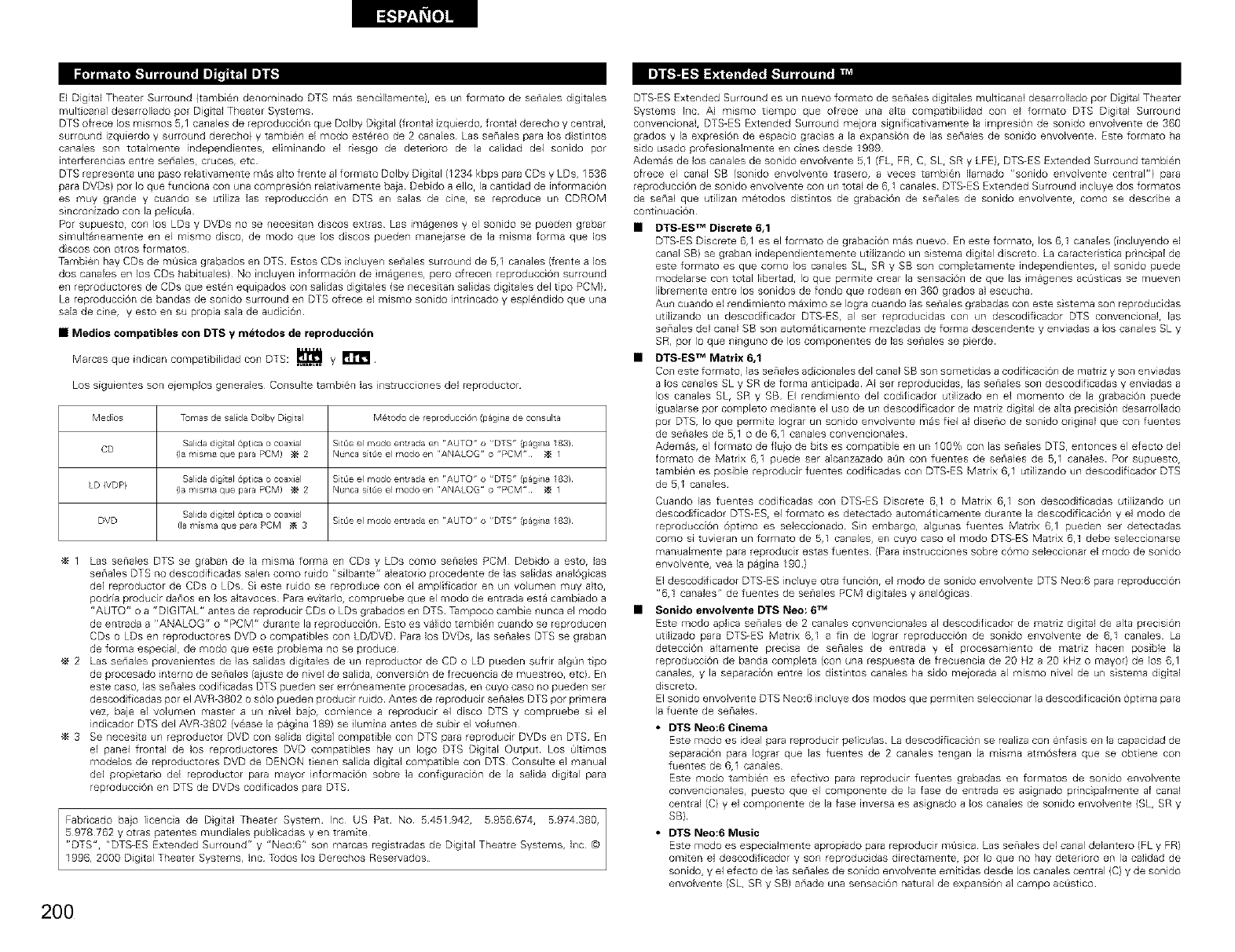
El Digital Theater Surround (tambien denominado DTS mas sencillamente), es un formato de senales digitales
multicanal desarrollado pot Digital TheateE Systems
DTS ofrece los mismos 5,1 canales de reproducciOn que Dolby Dgtal (frontal izquierdo, fro_tal derecho y central,
surround izquierdo y surround derecho} y tambi0n el modo estereo de 2 canaEes Las senales para los d stintos
canales son totalmente independientes, eliminando el nesgo de detenoro de la calidad del sonido pot
inter[erencias entre seriales, cruces, etc
DTS representa una paso relativamente mas alto frente al formato Dolby Dig tal (1234 kbps para CDs y LDs, 1536
para DVDs} pot Io que funciona con una compresi6n relativamente baja Debido a eliot la cantidad de informaciOn
es muy grande y cuando se utiliza las reproducci6n en DTS en salas de cine, se reproduce un CDROM
sincronizado con la pelicula
Pot supuesto, con los LDs y DVDs no se necesitan dscos extras Las imagenes y el sonido se pueden grabar
simultaneamente en el mismo disco, de modo que los discos pueden manejarse de la misma forma que los
discos con o'_ros formatos
Tambien hay CDs de mQsica grabados en DTS Estos CDs incluyen senales surround de 5,1 canales (frente a los
dos canales en los CDs habituales) No incluyen informaci6n de magenes, pero ofrecen reproduccion surround
en reproductores de CDs que esten equipados con salidas digitales (se necesitan salidas dig tales de1tipo PCM)
La reproducci6n de bandas de sonido surround en DTS ofrece el mismo sonido intrincado y esplendido que una
sala de cine, y esto en su propia sala de audicion
•Medios compatibles con DTS y metodos de reproduccion
Marcus que indican compat bilidad con DTS: _ y
Los siguientes son e}emplos generales Cow,suite tambien las i_struccio_es del reproductor
Medos Tomas de salJda Doby Digit a M_todo de reproducci6n (p_gi/a de co/sulta
Salida dgtal 6ptica o coaxial SitOe el rnodo elltr ada en 'AUTO" o "DTS" (p_gi/a 183)
CD (la r,/isr,/a que para PCM) _ 2 Nunca s[tSe e modo en ANALOG" o "PCM" _ 1
Salida dgtal 6ptica o coaxial SitOe el rnodo elltr ada en 'AUTO" o "DTS" (p_gi/a 183)
LD {VDP} (la r,/isr,/a que para PCM) _ 2 Nunca s[tSe e modo en ANALOG" o "PCM" _ 1
Salida dgtal 6ptica o coaxial
DVD (la ¥_[sma que para PCM _ 3 SitOe el rnodo entrada e/ AUTO" o "DTS" (p_gi/a 183)
1 Las senales DTS se graban de la misma forma e_ CDs y LDs como senales PCM Debdo a esto, las
seriales DTS no descodificadas salen como ruido "silbante" aleatodo procedente de las salidas analOglcas
del reproductor de CDs o LDs Si este ruido se reproduce con el amplificador en un volumen muy alto,
podria producir danos en los akavoces Para evitado, compruebe que el modo de entrada esta cambiado a
"AUTO" o a "DIGITAL" antes de reproducir CDs o LDs grabados en DTS Tampoco cambie nunca el modo
de entrada a "ANALOG" o "PCM" durante la reproducci6n Esto es valido tamb en cuando se reproducen
CDs o LDs en reproductores DVD o compatibles con LD/DVD Para los DVDs, las senales DTS se graban
de forma especial, de modo que este problema no se produce
2 Las seriales provenientes de 1as salidas digitales de un reproductor de CD o LD pueden sufrir algQn tipo
de procesado interno de senales (ajuste de nivel de salida, conversi6n de frecuencia de muestreo, etc) En
este caso, las senales codif cadas DTS pueden ser erroneamente procesadas, en cuyo caso no pueden set
descod ficadas pot el AVR-3802 o sOlo pueden producir ruido Antes de reproducir senales DTS por pnmera
vez, baje el volumen master a un nivel baior comlence a reproducir el disco DTS y compruebe s el
indicador DTS de1 AVR-3802 (vease la pagina 189) se lumina antes de subir el volumen
3 Se necesita un reproductor DVD con salida digital compatible con DTS para reproducir DVDs en DTS En
el panel frontal de los reproductores DVD compatibles hay un logo DTS Dgital Output Los Okimos
modelos de reproductores DVD de DENON tienen salida digital compatible con DTS Consulte el manual
del propietado del reproductor para mayor informacion sobre la configuraciOn de ]a salida digtal para
reproduccion en DTS de DVDs codificados para DTS
1996, 2000 Digtal Theater Systems, Inc Tudos los Derechos Reservados
200
DTS-ES Extended Surround es un nuevo formato de senales digitales multicanal desarrollado por Dig tal Theater
Systems Inc AI mismo tiempo que ofrece una alta compatibilidad con el formato DTS Digilal Surround
convencional, DTS-ES Extended Surround mejora signif cativamente la impresion de sonido envolvente de 360
grados y la expresion de espac_o gracias a la expansion de las seriales de sonido envolvente Este formato ha
sido usado profesionalmente en cines desde 1999
Ademas de los canales de sonido envolvente 5,1 (EL, FR, C, SL, SR y LFE}, DTS-ES Extended Surround tambien
ofrece el canal SB (sonido envolvente trasero, a veces tambien Ilamado "sonido envolvente central"} para
reproducci0n de sonido envolvente con un total de 6,1 canales DTS-ES Extended Surround incluye dos formatos
de senal que utlizan metodos dist ntos de grabacion de senales de sonido envolvente, como se describe a
continuacion
•DTS-ES TM Discrete 6,1
DTS-ES Discrete 6,1 es el formato de grabacion mas nuevo En este formato, los 6,1 canales (i_cluyendo el
canal SBI se graban independientemente utilizando un sistema digtal discreto La caracteristica pr ncipal de
este formato es que como los canales SL, SR y SB son completamente independientes, el sonido puede
modelarse con total libertad, Io que permite crear la sensacion de que las magenes ac0sticas se mueven
libremente entre los sonidos de rondo que rodean en 360 grados al escucha
Aun cuando el rendimiento maximo se Iogra cuando las senales grabadas con este sistema son reproducidas
utilizando un descodificador DTS-ES, al ser reproducidas con un descodiScador DTS convencional, las
seriales del canal SB son automaticamente mezcladas de forma descendente y enviadas a los canales SLy
SR, pot Io que ninguno de los componentes de las senales se pierde
•DTS-ES TM Matrix 6,1
Co_ este formato, ]as senales adicio_ales del canal SB son sometidas a codificacion de matdz y son enviadas
a los canales SLy SR de forma anticipada AI ser reproducidas, las senales son descodificadas y enviadas a
los canales SL, SR y SB El rendimiento del codificador utilizado en el momento de la grabacion puede
igualarse por completo mediante el uso de un descodificador de matriz digtal de alta precision desarrollado
pot DTS, Io que permite Iograr un sonido envolvente mas fie1 al diseno de sonido odg nal que con fuentes
de senales de 5,1 o de 6,1 canales convencionales
Ademas, el formato de fiujo de hits es compatible en un 100% con las senales DTS, entonces el efecto del
formato de Matrix 6,1 puede ser alcanzazado aOn con fuentes de seriales de 5,1 canales Pot supuesto,
tambien es posible reproducir fuentes codificadas con DTS-ES Matrix 6,1 utilizando un descodificador DTS
de 5,1 canales
Cuando las fuentes codiScadas con DTS-ES Discrete 6,1 o Matrix 6,1 son descodficadas utilizando un
descodificador DTS-ES, el formato es detectado automaticamente durante la descodificacion y el modo de
reproduccion opPmo es seleccionado Sin embargo, algunas fuentes Matrix 6,1 pueden set detectadas
como si tuvieran un formato de 5,1 canales, en cuyo caso el modo DTS-ES Matrix 6,1 debe seleccionarse
manualmente para reproducir estas fuentes (Rata instrucciones sobre c0mo seleccionar el modo de sonido
envolvente, yea la pagina 190}
El descod ficador DTS-ES induye otra funcion, el modo de sonido envolvente DTS Neo:6 para reproduccion
"6,1 canales" de fuentes de senales PCM digitales y analogicas
•Sonido envolvente DTS Nee: 6 TM
Este modo aplica senales de 2 canales corwencionales al descod flcador de matdz digital de alta pre_ision
utilizado para DTS-ES Matrix 6r_ a fin de Iograr reproducciO_] de sonido e_wolvente de 6,1 canales La
deteccion akamente precisa de senales de entrada y el procesamiento de matdz hacen posible la
reproducciOn de banda completa (con una respuesta de frecuencia de 20 Nz a 20 kHz o mayor} de los 6,1
canales, y la separaciOn entre los distintos canales ha sido meiorada al mismo nivel de un sistema digital
discreto
El so_ido envolvente DTS Neo:6 incluye dos modos que permiten seleccionar la descodificacion Optima para
la fuente de senales
• DTS Neo:6Cinema
Este modo es ideal para reproducir peliculas La descodificaciOn se realiza con enfasis en la capacidad de
separaciO_ para Iograr que ias fuentes de 2 canales tengan la misma atmosfera que se obtiene con
fuentes de 6,1 canales
Este modo tambien es efectivo para reproducir fuentes grabadas en formatos de sonido envolvente
convencionales, puesto que el componente de la fase de entrada es asignado principalmente al canal
central (C} y el componente de la fuse inversa es aslgnado a los canales de sonido envolvente {SL, SR y
SB}
•DTS Neo:6 Music
Este modo es especialmente apropiado para reproducir m_isica Las senales del ca_al delantero (FLy FR}
omiten el descod ficador y son reproducidas directamente, pot Io que no hay detedoro en la calidad de
sonido, y el efecto de las senales de sonido envolvente emitidas desde los canales central (C) y de sonido
envolvente (SL, SR y SB) ariade una sensacion natural de expansion al campo acQstico
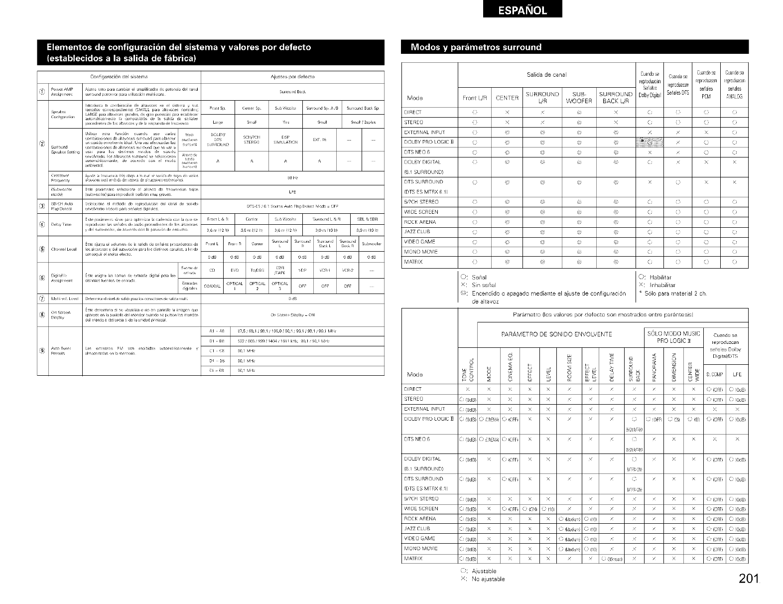
Conf_gu_ci6ndelsiste_n_
Aius_es i_r de_ecto
L_
CD DV_ TV_DBS r '/DP VCR,I VCR,2
C _X_A, OPTiCaL OPTICAL OPTICAL O _ O _ O _
Cl ( 90,! MH__
_i • _ 90,! MH__
_1 - _ 90,! MH__
Mode
DIRECT
STERE()
EXTERNAL INPLT
DOLBY PRO LOGIC ]]
DTS NEO6
DOLBY DIGITAL
(6 I SURROUND)
DTS SURROUND
(DTS ES MTRX 6 /}
_TCH _EREO
WIDE SCREEN
ROCK ASEKA
JAZZ CLUB
VIDE(} GAME
MOI'_(} MOVIE
MATRIX
Mode
DIRECT
STERE()
EXTERNAL INPLT
DOLBY PRO LOGIC ]]
Fro/t L/R CENTER
Cusnd0se CuaxJ6se
Salida de ca/al Cua1dose C.andos_
[_oduz_fi _epl_ZCa_l [epc0duzcafl
Scab!es !_ _0"_uzca_ _aies _al_
SURROUND SUB SURROUND D_lb_Digit_!%i_iesDTS PCk! _N_LOG
L/R WOOFER BACK L/R
( x x (i (3 } )
( x x (i (3 } )
( _ @ } i
(2 _ @ (i x >
C _ @ ( x >
(2 _ @ (i ( } )
(2 _ @ (i ( } )
( _ @ (i ( } )
( _ @ (i ( } )
( _ @ (i ( } )
( _ @ (i ( } )
( _ @ (i ( } )
se,,o,
:Sin sei'al
Encendido o apagado mediallte el aiuste de configuracidn
de altavoz
Parametro (los valores pot defecto son mostrados entre pa r_/tesis)
o8
>
( (0dB
( (0dB
( (0dB
PARAMETRO DE SONIDO ENVOLVENTE
8
> > x x
> > x x
> > x x
( :i,E_,: ((OFF) X X
DTS NEE}(> ( (0dB ( :'E_': ( (FF X X
DOLBY DIGITAL (i (0dBi >_ (i iOFF) X X _ _ _
(6 I SURROUND)
DTS SURROUND (i (0dBi >_ (i iOFF) X X _ _ _
(DTS ES MTRX 6 /}
_TCH _EREO (i (0dBi >_ >_ X X _ _ _
WIDE SCREEN (i(0dBi >_ (iiOFF) _) ion} } i/9 _ _ _
ROCK ASEKA ( i (0dBi >_ >_ X X O i_diu_q (}(1_ _
MOb20 MOVIE (i (0dBi >_ >_ X X _) i_diu_q (} (1_ _
SOLO MODO MUSC Cuandose
PRO LOGIC II repru_luzcafl
set_aiesDollW
< S
/ / ( (OFF ( (0dB
/ / ( (OFF ( (0dB
£ £ X X
(} (} OFF (} (3] (} (0/ ( (OFF ( (0dB
SpY _8
(} £ X X
SpY _8
(} /( (OFF ( (0dB
V-X0
(} /( (OFF ( (0dB
V-X0
/ / ( (OFF ( (0dB
/ / ( (OFF ( (0dB
/ / ( (OFF ( (0dB
/ / ( (OFF ( (0dB
/ / ( (OFF ( (0dB
/ / ( (OFF ( (0dB
/ / ( (OFF ( (0dB
k_: Aiustable
x No ajustable 201
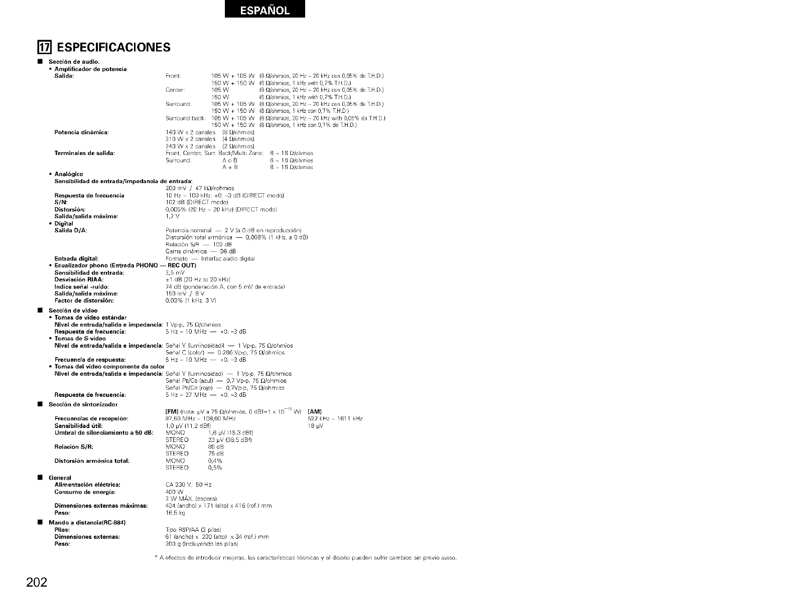
[] ESPECIFICACIONES
•Secci6n de audio.
•Ampliflcador de potencla
Sallda:
Potencla dln_mlca:
Termlnales de sallda:
•Anal6glco
FroTlt: 105 W + 105 W (8 £1/ohmios 20 HZ 20 kHz con 0,05% de TH D }
150W+150W (6_/ohmios lkHzwith07%THD}
Center: 105 W (8 _/ohmios 20 Hz - 20 kHz cen 0,05% de TH D }
150 W (6 _/ohmios 1 kHz with 07% THD}
SurrouTld 105 W + 105 W (8 _/ohmios 20 Hz - 20 ]<Hz cen 0,05% de TH D}
150W+150W (6_/ohmios lkHzcon07%THD}
SurrouTld back: 105 W + 105 W (8 _/ohmios 20 HZ _ 20 kHz with 0,05% de TH D}
150W+150W (6_dohmios lkHzcon07%deTHD)
140 W x 2 canales (8 _/ohmios)
210 W x 2 canales (4 _/ohmios)
240 W x 2 canales (2 _/ohmios)
FroTlt CeTlte_ Sum Back/Multi Zone: 6 N 16 O/o_/mios
SurrouTld A o B 6 N 16 _ol/mios
A + B 8 - 16 _ol/mios
Senslbilldad de entrada/impedancla de entrada:
200 mV /47 k_J/kohmios
Respuesta de frecuencla
SIN:
Distorsi6n:
Sallda/salidam_xlma:
•Digital
Sallda D/A:
Entrada digital:
10 I-z 100 kHz: +0 _ dB (DIRECT mode)
102 dB (DIRECT mode)
0,005% (20 Hz 20 kHz}(D_RECT mode)
1,2 V
Potenc;a rlorl'irla 2 V (a 0 dB en reproducc[6n}
DJstorsi611 tota arm6n ca 0,008% (I kHz, a 0 dB)
Relac 6_/ S/R 102 dB
Garla din_r,/Jca 96 dB
Formsto Interfaz audio digital
•[cuallzador phone {Entrada PHONe -- REC OUT}
$ensibilidad de entrada: 2,5 r'lV
Desviaci6n RIAA: +1 dB (20 Hz to 20 kHz)
Indlce sepal -ruldo: 74 dB (ponderaciTn A, coT15 mV de el/t rada)
Sallda/salida m_xima: 150 mV /8 V
Factor de dlstorsi6n: 0,03% (1 kHz 3 V)
•Secci6n de video
•Tomas de video est_ndar
Nivel de entrada/sallda e impedancla: I V_p, 7S O/ohmios
Respuesta de frecuencla: 5 Hz - 10 MHz +0, _ dB
•Tomas de S-video
Nivel de entrada/salida e impedancia: Senal Y (lum[nosidad}l 1 V_p, 75 O/ohmios
Sena] C (color} 0¸286 V_p, ?50/ohmios
Frecuencla de respuesta: 5 Hz _ 10 MHz +0, _ dB
•Tomas del video componente de color
Nivel de entrada/salida e impedancia: Sena] Y (lum[nosidad} I Vp p 75 _/ohmios
SenaJ PB/CB (azul) 0,7 Vp p, 75 _2/ohmios
Senal PWCR (r o]o) O?Vp p, 75 _)/ohmios
Respuesta de frecuencia: 5 Hz 27 MHz _0, _ dB
•Secci6n de slntonlzador
IFMI (nora: MV a 75 _/ohmios, 0 dBf 1 x O B W} [AM]
Frecuenclas de recepci6n: 87,50 MHz 10800 MHz
Sensibilidad _til: 1,0 _V ( 12 dBf)
Umbral de silenclamiento a50 dB: MONO 1,6 _V (l 5,3 dBf)
STEREO 23 pV (38,5 dBf)
Flelaci6n SIR: MONO 80 dB
STEREO ?5 dB
Distorsi_n arm6nlca total: MONO 0,4%
STEREO 0,5%
•General
AIimentaci_n el_trlca:
Consume de energla:
Dimenslo_es externasm_ximas:
Peso:
•Mando adista_cia(RC-884}
Pilas:
Dimenslo_esexternas:
Peso:
CA 230 V 50Hz
400 W
2 W MAX (espera)
434 (ancho) x 171 (alto) x 416 (rof) m¥_
16,5 g
_po R6P/AA (3 pilas)
61 (ancho} x 230 (ate) x 34 (rof } mm
200 g (Incluyendo las pilas}
522kHz 1611 kHz
18 #V
Adectos de [ntroduo[r mejoras, las caracter[sticas t_c_[cas y e diseno pueden sdir car,/bios Si/ prev[o arise
202
