Denon DRA 685 User Manual AM FM STEREO RECEIVER Manuals And Guides L0211064
DENON Receivers Manual L0211064 DENON Receivers Owner's Manual, DENON Receivers installation guides
User Manual: Denon DRA-685 DRA-685 DENON AM-FM STEREO RECEIVER - Manuals and Guides View the owners manual for your DENON AM-FM STEREO RECEIVER #DRA685. Home:Electronics Parts:Denon Parts:Denon AM-FM STEREO RECEIVER Manual
Open the PDF directly: View PDF ![]() .
.
Page Count: 56
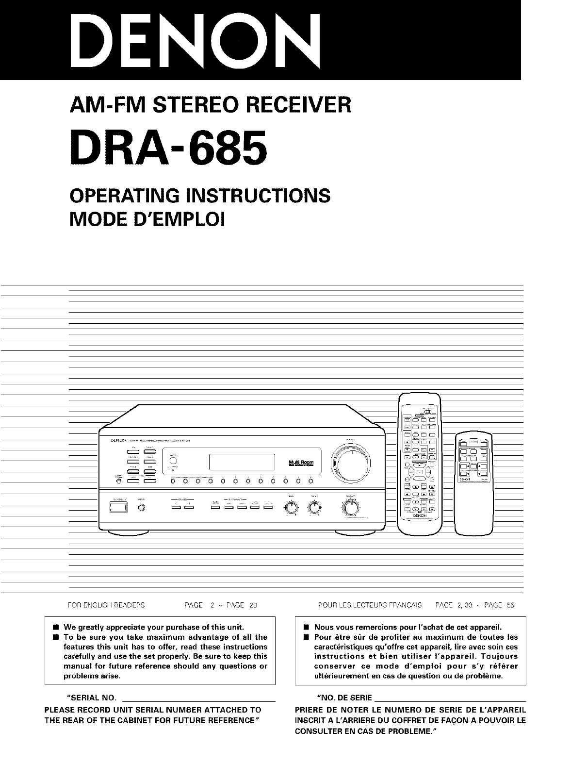
AM-FM STEREO RECEIVER
DRA-685
OPERATING INSTRUCTIONS
MODE D'EMPLOI
jr
o _ o o
Mull Room /
0000000000
Z_C
oO Oo ......
FOR ENGL(SH READERS PAGE 2 o- PAGE 29
•We greatly appreciate your purchase of this unit.
•To be sure you take maximum advantage of all the
features this unit has to offer, read these instructions
carefully and use the set properly. Be sure to keep this
manual for future reference should any questions or
problems arise.
"SERIAL NO.
PLEASE RECORD UNIT SERIAL NUMBER ATTACHED TO
THE REAR OF THE CABINET FOR FUTURE REFERENCE"
POUR LES LECTEURS FRANCAIS PAGE 2, 30 PAGE 55
•Nous vous remercions pour I'achat de cet appareil.
•Pour &tre s_r de profiter au maximum de toutes les
caracteristiques qu'offre cet appareil, life avec soin ces
instructions et bien utiliser I'appareil. Toujours
conserver ce mode d'emploi pour s'y referer
ulterieurement en cas de question ou de problbme.
"NO. DE SERIE
PRIERE DE NOTER LE NUMERO DE SERIE DE L'APPAREIL
INSCRIT A L'ARRIERE DU COFFRET DE FA(_ON A POUVOIR LE
CONSULTER EN CAS DE PROBLEME."
[_e,]_.,,_ F_ _]
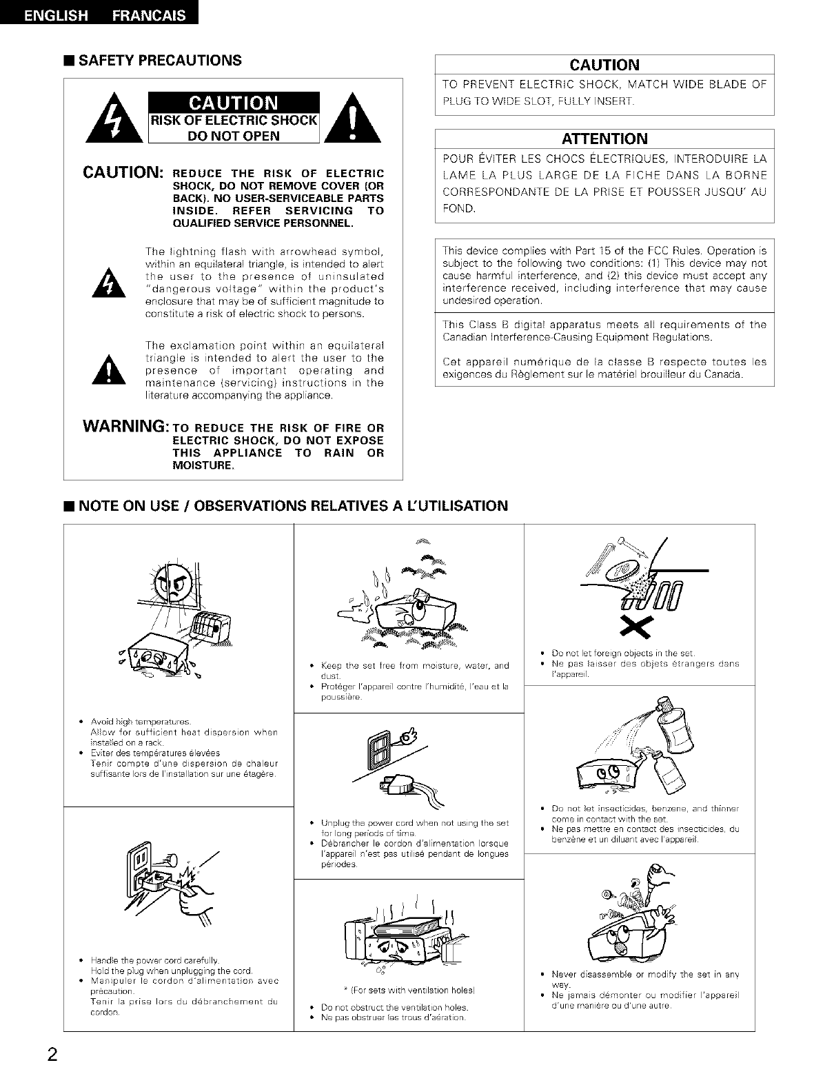
•SAFETY PRECAUTIONS
CAUTION: REDUCE THE RISK OF ELECTRIC
SHOCK, DO NOT REMOVE COVER (OR
BACK). NO USER-SERVICEABLE PARTS
INSIDE. REFER SERVICING TO
QUALIFIED SERVICE PERSONNEL.
The lightning flash with arrowhead symbol,
within an equilateral triangle, is intended to alert
the user to the presence of uninsulated
"dangerous voltage" within the product's
enclosure that may be of sufficient magnitude to
constitute a risk of electric shock to persons.
The exclamation point within an equilateral
triangle is intended to alert the user to the
presence of important operating and
maintenance (servicing) instructions in the
literature accompanying the appliance.
WARNING:To REDUCE THE RISK OF FIRE OR
ELECTRIC SHOCK, DO NOT EXPOSE
THIS APPLIANCE TO RAIN OR
MOISTURE.
CAUTION
TO PREVENT ELECTRIC SHOCK, MATCH WIDE BLADE OF
PLUG TO WIDE SLOT, FULLY INSERT
ATTENTION
POUR EVITER LES CHOCS ELECTRJQUES, INTERODUIRE LA
LAME LA PLUS LARGE DE LA FICHE DANS LA BORNE
CORRESPONDANTE DE LA PRISE ET POUSSER JUSQU' AU
FOND
This device complies with Part I5 of the FCC Rules Operation is
subject to the following two conditions: (1) This device may not
cause harmful interference, and (2) this device must accept any
interference received, including interference that may cause
undesired operation.
This Class B digital apparatus meets all requirements of the
Canadian Interference-Causing Equipment Regulations.
Cet appareil num@rique de la classe B respecte toutes les
exlgences du R_glement sur le materiel brouilleur du Canada.
•NOTE ON USE /OBSERVATIONS RELATIVES A L'UTILISATION
• Avo d h gh temperat=Jres
A}}ow for sufficient heat dissersion when
r stalled on a rack
• Eviter des temperatures @levees
Tent compte dr re dispersion de chaleur
s ffsarte lots de I'installation sur une 6tag_re
• Hand}e the sower cord carefully
Hold the plug when unplugging the cord
• Mampuler le cordon d'al mentat or avec
pr6ca tlon
Tenir la prise Iors du d@branchement du
cordon
• Keep the set free flom moisture, water, and
dust
• Prot@ger I'appareil contre I'humidd_, I'eau et la
poussi_re
• Unplug the power cord when r ot using the set
for long periods of time
• D6brancler le cordon d'almentation }orsque
I'appareil r'est sas utilis@ pendant de Iongues
p@riodes
* (For sets with ventilation holes)
• Donotobstructt eventilation holes
• Nepasobstruer estro sdra@ration
• Do not let foreign obiects in the set
• Ne pas }aissel des obets @trangers dans
'a_areil
• Do not }et nsect cides, benzene, and thinner
come in contact with the set
• Ne pas mettre en contact des insecticides, d
benzane et un diluant avec I'appare
• Never disassembe or modify the set in any
way
• Ne jamas d@monter ou rood fier I'apsarel
drune mani@re ou d'une autre
2
1.
2.
3.
4.
5.
6.
7.
8.
g.
10.
11.
12.
SAFETY INSTRUCTIONS
Read Instructions - All the safety and operating instructions
should be read before the product is operated.
Retain Instructions - The safety and operating instructions
should be retained for future reference
Heed Warnings -AII warnings on the product and in the
operating instructions should be adhered to
Follow Instructions -All operating and use instructions should
be followed.
Cleaning -Unplug this product from the wall outlet before
cleaning Do not use liquid cleaners or aerosol cleaners.
Attachments -Do not use attachments not recommended by
the product manufacturer as they may cause hazards
Water and Moisture -Do not use this product near water -for
example, near a bath tub, wash bowl, kitchen sink, or laundry
tub; in a wet basement; or near a swimming pool; and the like.
Accessories -Do not place this product on an unstable cart,
stand, tripod, bracket, or table The product may fall, causing
serious injury to a child or adult, and serious damage to the
product. Use only with a cart, stand, tripod, bracket, or table
recommended by the manufacturer, or sold with the product.
Any mounting of the product should follow the manufacturer's
instructions, and should use a
mounting accessory
recommended by the
manufacturer.
A product and cart
combination should be
moved with care Quick
stops, excessive force,
and uneven surfaces may
cause the product and cart
combination to overturn
Ventilation -Slots and openings in the cabinet are provided for
ventilation and to ensure reliable operation of the product and
to protect it from overheating, and these openings must not be
blocked or covered. The openings should never be blocked by
placing the product on a bed, sofa, rug, or other similar
surface This product should not be placed in a built in
installation such as a bookcase or rack unless proper
ventilation is provided or the manufacturer's instructions have
been adhered to
Power Sources -This product should be operated only from
the type of power source indicated on the marking label. If
you are not sure of the type of power supply to your home,
consult your product dealer or local power company. For
products intended to operate from battery power, or other
sources, refer to the operating instructions.
Grounding or Polarization -This product may be equipped with
a polarized alternating=current line plug (a plug having one
blade wider than the other). This plug will fit into the power
outlet only one way. This is a safety feature If you are unable
to insert the plug fully into the outlet, try reversing the plug If
the plug should still fail to fit, contact your electrician to replace
your obsolete outlet Do not defeat the safety purpose of the
polarized plug
13 Power-Cord Protection -Power=supply cords should be routed
so that they are not likely to be walked on or pinched by items
placed upon or against them, paying particular attention to
cords at plugs, convenience receptacles, and the point where
they exit from the product.
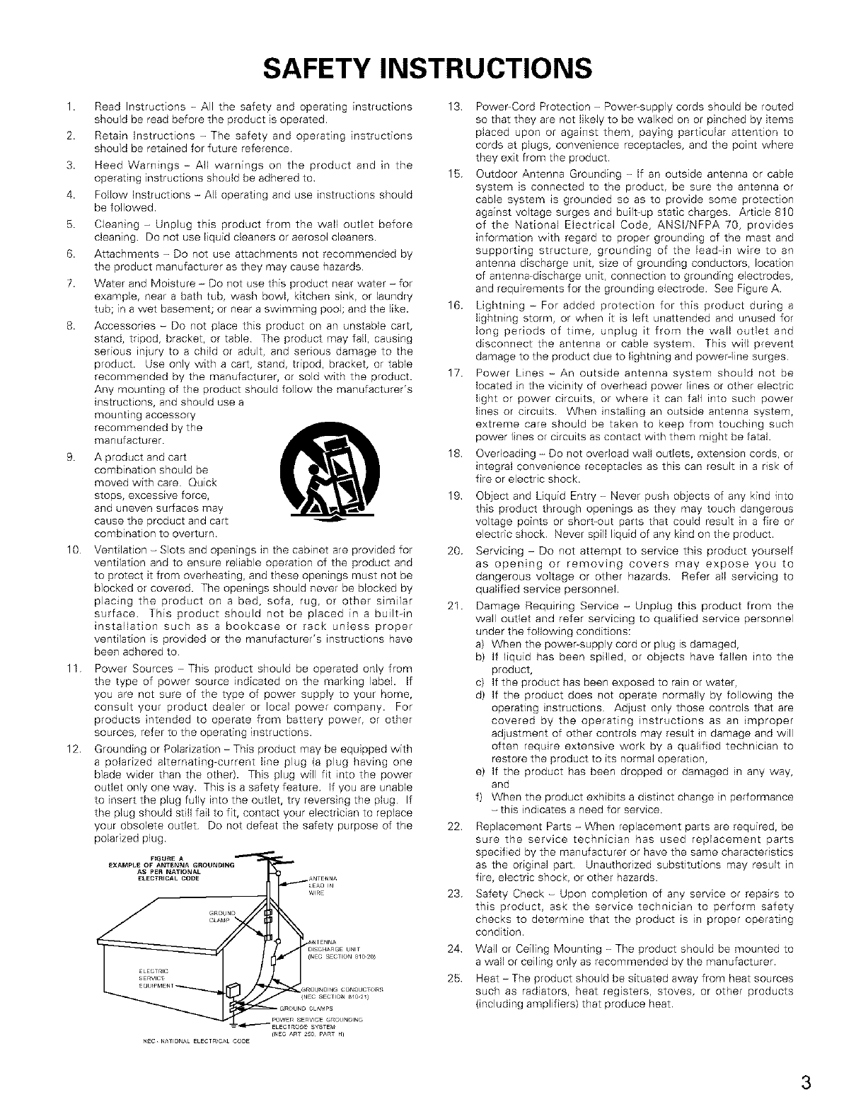
15 Outdoor Antenna Grounding -If an outside antenna or cable
system is connected to the product, be sure the antenna or
cable system is grounded so as to provide some protection
against voltage surges and built=up static charges. Article 810
of the National Electrical Code, ANSI/NFPA 70, provides
information with regard to proper grounding of the mast and
supporting structure, grounding of the leaddn wire to an
antenna discharge unit, size of grounding conductors, location
of antenna=discharge unit, connection to grounding electrodes,
and requirements for the grounding electrode See Figure A.
16 Lightning -For added protection for this product during a
lightning storm, or when it is left unattended and unused for
long periods of time, unplug it from the wall outlet and
disconnect the antenna or cable system This will prevent
damage to the product due to lightning and powerqine surges
17 Power Lines- An outside antenna system should not be
located in the vicinity of overhead power lines or other electric
light or power circuits, or where it can fall into such power
lines or circuits. When installing an outside antenna system,
extreme care should be taken to keep from touching such
power lines or circuits as contact with them might be fatal.
18 Overloading -Do not overload wall outlets, extension cords, or
integral convenience receptacles as this can result in a risk of
fire or electric shock.
19
20.
21.
Object and Liquid Entry -Never push objects of any kind into
this product through openings as they may touch dangerous
voltage points or short=out parts that could result in a fire or
electric shock Never spill liquid of any kind on the product.
Servicing -Do not attempt to service this product yourself
as opening or removing covers may expose you to
dangerous voltage or other hazards. Refer all servicing to
qualified service personnel.
Damage Requiring Service -Unplug this product from the
wall outlet and refer servicing to qualified service personnel
under the following conditions:
a) When the power supply cord or plug is damaged,
b) If liquid has been spilled, or objects have fallen into the
product,
c) If the product has been exposed to rain or water,
d) If the product does not operate normally by following the
operating instructions Adjust only those controls that are
covered by the operating instructions as an improper
adjustment of other controls may result in damage and will
often require extensive work by a qualified technician to
restore the product to its normal operation,
e) If the product has been dropped or damaged in any way,
and
f) When the product exhibits a distinct change in performance
-this indicates a need for service.
22 Replacement Parts -When replacement parts are required, be
sure the service technician has used replacement parts
specified by the manufacturer or have the same characteristics
as the original part Unauthorized substitutions may result in
fire, electric shock, or other hazards
23 Safety Check -Upon completion of any service or repairs to
this product, ask the service technician to perform safety
checks to determine that the product is in proper operating
condition.
24 Wall or Ceiling Mounting -The product should be mounted to
a wall or ceiling only as recommended by the manufacturer.
25 Heat -The product should be situated away from heat sources
such as radiators, heat registers, stoves, or other products
(including amplifiers) that produce heat
(NEC ART 25O PART H]
NEC NATIONAL ELECTR_CA_ CODE
3
_t]]E-t]][
•INTRODUCTION
Thank you for choosing the DENON AM-FM Stereo receiver. This remarkable component has been engineered to provide outstanding high
fidelity reproduction of your favorite music sources.
As this product is provided with an immense array of features, we recommend that before you begin hookup and operation that you review the
contents of this manual before proceeding
TABLE OF CONTENTS
Before Using .................................................................. 4
Cautions on Installation ...................................................... 5
Cautions on Handling ......................................................... 5
Features ........................................................................ 5
Connections ............................................................... 6-10
Part Names and Functions .......................................... 10, 11
Remote Control Unit ................................................... 12-17
Operations ............................................................... 17-23
Listening to the Radio ................................................ 24-26
El Initialization of the Microprocessor .................................... 27
Last function memory ...................................................... 27
Troubleshooting ............................................................ 28
El Specifications ............................................................... 29
•ACCESSORIES
Check that the following parts are included in addition to the main unit:
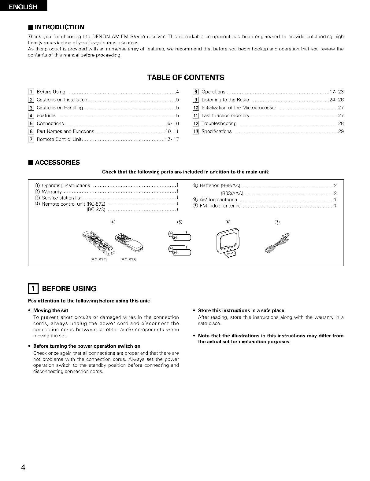
(1) Operating instructions ...................................................
(2) Warranty .....................................................................
(3) Service station lisl .........................................................
(4) Remote control unit (RC_872) ..........................................
(RC-873) ..........................................
(5} Batteries (R6P/AA) ......................................................... 2
(R03/AAA) ...................................................... 2
(6} AM loop antenna ......................................................... 1
(7} FM indoor antenna ......................................................... 1
(RC-872) (RC-873)
® ® ®
[] BEFORE USING
Pay attention to the following before using this unit:
•Moving the set
To prevent short circuits or damaged wires in the connection
cords, always unplug the power cord and disconnect the
connection cords between all other audio components when
moving the set.
•Before turning the power operation switch on
Check once again that all connections are proper and that there are
not problems with the connection cords. Always set the power
operation switch to the standby position before connecting and
disconnecting connection cords.
•Store this instructions in a safe place.
After reading, store this instructions along with the warranty in a
safe place
•Note that the illustrations in this instructions may differ from
the actual set for explanation purposes.
4
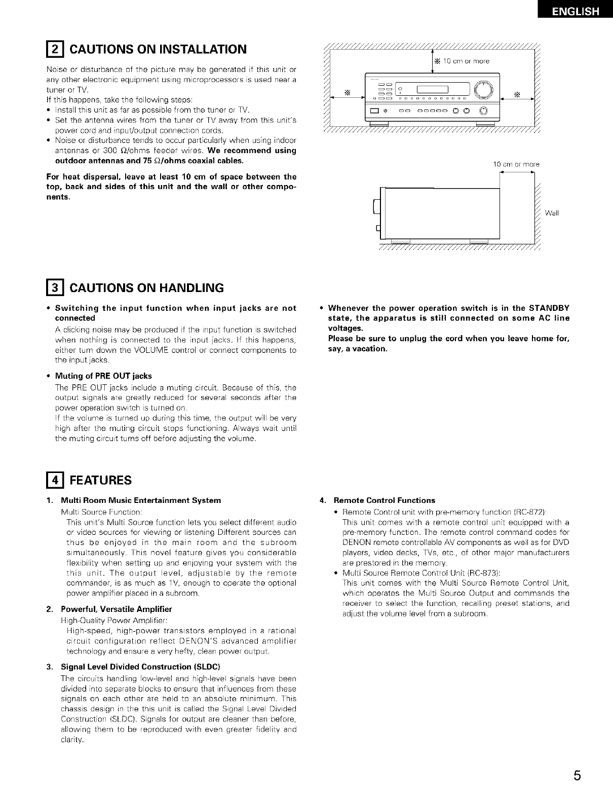
[] CAUTIONS ON INSTALLATION
Noise or disturbance of the picture may be generated if this unit or
any other electronic equipment using microprocessors is used near a
tuner or TV.
If this happens, take the following steps:
• Install this unit as far as possible from the tuner or TV
• Set the antenna wires from the tuner or TV away from this unit's
power cord and input/output connection cords.
• Noise or disturbance tends to occur particularly when using indoor
antennas or 300 £_/ohms feeder wires. We recommend using
outdoor antennas and 75 £_/ohms coaxial cables.
For heat dispersal, leave at least 10 cm of space between the
top, back and sides of this unit and the wall or other compo-
nents.
///////////////////////////////////////////////,,
N 10 cm or more
* ....... OO © [
"//////////////////////////////////////////////,
10 Cm or more
////////////////////////////////////
Wall
[] CAUTIONS ON HANDLING
• Switching the input function when input jacks are not
connected
A clickhTg noise may be produced if the input function is switched
when nothing is connected to the input jacks. If this happens,
either turn down the VOLUME control or connect components to
the input jacks.
•Muting of PRE OUT jacks
The PRE OUT iacks include a muting circuit Because of this, the
output signals are greatly reduced for several seconds after the
power operation switch is turned on
If the volume is turned up during this time, the output will be very
high after the muting circuit stops functioning. Always wait until
the muting circuit turns off before adjusting the volume
•Whenever the power operation switch is in the STANDBY
state, the apparatus is still connected on some AC line
voltages.
Please be sure to unplug the cord when you leave home for,
say, a vacation.
[] FEATURES
1. Multi Room Music Entertainment System
Multi Source Function:
This unit's Multi Source function lets you select different audio
or video sources for viewing or listening Different sources can
thus be enjoyed in the main room and the subroom
simultaneously This novel feature gives you considerable
flexibility when setting up and enjoying your system with the
this unit. The output level, adjustable by the remote
commander, is as much as lV, enough to operate the optional
power amplifier placed in a subroom
2, Powerful, Versatile Amplifier
High-Quality Power Amplifier:
High-speed, high-power transistors employed in a rational
circuit configuration reflect DENON'S advanced amplifier
technology and ensure a very hefty, dean power output.
3. Signal Level Divided Construction (SLDC)
The circuits handling low level and highqevel signals have been
divided into separate blocks to ensure that influences from these
signals on each other are held to an absolute minimum This
chassis design in the this unit is called the Signal Level Divided
Construction (SLDC) Signals for output are cleaner than before,
allowing them to be reproduced with even greater fidelity and
clarity.
4. Remote Control Functions
• Remote Control unit with pre-memory function (RC_872):
This unit comes with a remote control unit equipped with a
pro-memory function. The remote control command codes for
DENON remote controllable AV components as well as for DVD
players, video decks, TVs, etc, of other major manufacturers
are prestored in the memory
• Multi Source Remote Control Unit (RC=873):
This unit comes with the Multi Source Remote Control Unit,
which operates the Multi Source Output and commands the
receiver to select the function, recalling preset stations, and
adjust the volume level from a subroom
5
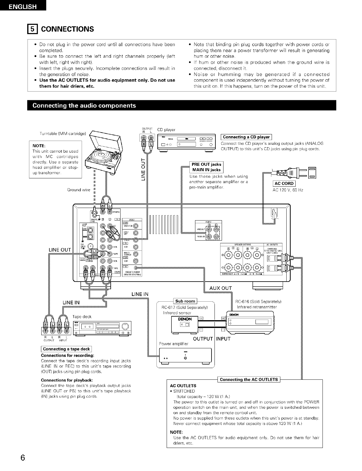
[] CONNECTIONS
•Do not plug in the power cord until aft connections have been
completed.
• Be sure to connect the left and right channels propedy (left
with left, right with right)
• Insert the plugs securely. Incomplete connections will result in
the generation of noise
•Use the AC OUTLETS for audio equipment only. Do not use
them for hair driers, etc.
• Note that binding pin plug cords together with power cords or
placing them near a power transformer will result in generating
hum or other noise
• If hum or other no4se is produced when the ground wire is
connected, disconnect it
• Noise or humming may be generated if a connected
component is used independently without turning the power of
this unit on If this happens, turn on the power of the this unit.
Ground wire
LINE OUT i
LiNE IN
Tape deck
©
[ Connecting a tape deck ]
Connections for recording:
Co_wlect the tape deck's recording input iacks
(LINE IN or REC) to this u_fit's tape recording
(OUT) jacks using pin plug cords
Connections for playback:
Connect the tape deck's playback output iacks
(LINE OUT or PB) to this unt's tape playback
(IN) jacks using pin plug cords
LINE iN
OL >JT CD player
L
_oo _o °° IConnecting a CD player I
Connect the CD player's analog output jacks (ANALOG
OUTPUT) to this unit's CD iacks using pin plug cords¸
Use these jacks when using
another separate amplifier or a
pre-maln ampl fief AC 120 V, 60 Hz
AUX OUT
RC-617 (Sold Separately)
Infrared sensor
DENON
[]
OUTPUT INPUT
Power amplifier
-l
RC-616 (Sold Separately)
Infrared retransmitter
[Connecting the AC OUTLETS }
AC OUTLETS
• SWITCHED
(total capacity -120 W (1 A)
The power to this outlet is turned on and off in conjunction with the POWER
operation switch on the main unit, and when the power is switched between
on and otandby from the remote control unit¸
No power is supplied from these outlets when this unit's power is at standby¸
Never connect equipment whose total capacity is above 120 W (1 A)
NOTE:
Use the AC OUTLETS for audio equipment only Do not use them for hair
driers, etc
6
[_i_e]]![.l][
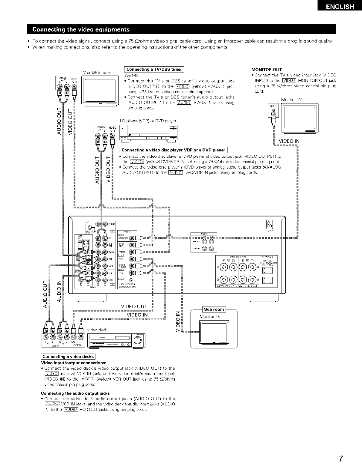
• To connect the video signal, connect using a 75 _/ohms video signal cable cord Using an improper cable can result in a drop in sound quality
• When making connections, also refer to the operating instructions of the other components
5
©
©
TV or DBS tuner
o VIDEa 1]
k OdT
IConnecting a TV/DBS tuner
TV/DBS
• Connect the TV's or DBS tuner's video output iack
(VDEO OUTPUT) to the _ (yellow) VAUX IN jack
using a 75 _Z/uhms video coaxial pin plug cord
• Connect the TV's or DBS tuner's audio output jacks
(AUDIO OUTPUT) to the _ VAUX IN jacks using
pin plug cords
5
©
©
MONITOR OUT
• Connect the TV's video input jack (VDEO
INPUT) to the _ MONITOR OUT jack
using a 75 _/uhms video coaxial pin plug
cord
LD player (VDP) or DVD player
L OU
.... _Z
IConnecting a video disc player VDP or a DVD player I
• Connect the video disc player's (DVD player's) video output jack (VIDEO OUTPUT) to
the _ (yellow) DVD/VDP IN jack using a 75 £_/ohms video coaxial pin plug cord
• Connect the video disc player's (DVD player's) analog audio output iacks (ANALOG
AUDIO OUTPUT) to the _ DVD/VDP IN jacks using pn plug cords
VIDEO OUT
VIDEO IN
Monitor _V
_J
Connecting a video decks ]
Video input/output connections:
• Connect the video deck's video output jack (VIDEO OUT) to the
(yellow} VCR IN jack, and the video deck's video input jack
(VIDEO IN) to the _ (yellow) VCR OUT jack using 75 _/ohms
video coaxial pin plug cords
Connecting the audio output jacks
• Connect the video deck audio output jacks (AUDIO OUT) to the
VCR IN jacks, and the video deck's audio input iacks (AUDIO
IN) to the _ VCR OUT jacks using pin plug cords¸
7
DIRECTION OF
BROADCASTING
STATION
/FM ANTENNA
75_ohms
COAXIAL
CABLE
AM LOOP
ANTENNA
(An Accesso W)
_?@ .....
_, @@ o .........@
,_S_D'_D_aVD
@ @..... _,o_@
0,,..... @@, ............
@@1@@,,_, _ ®
_LUO0 R_4_T_C_NR_ i
///_ ////
GROUND
AM OUTDOOR
ANTENNA
FM INDOOR ANTENNA
(An Accesso W)
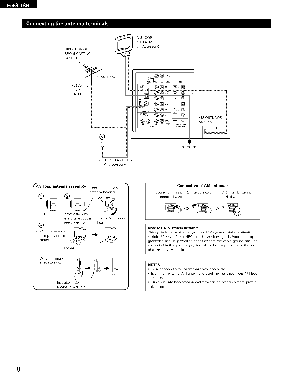
fANI loop antenna assembly Connect to the AM
a rite n1_8 terminals
©
Remove the vinyl
tie and take out the Bend in the reverse
(_ connection line direction
a With the antenna
on top any stabJe '_
suFrace
Mount
b Wtt_{{_t/Iteantwe_nlna _ _1_ _1_ _L_
Insdlation hole
Mount on wall, etc J
Connection of AM antennas
1 Loosen by turning 2 Inset tee cord 3 Tighten by turning
counterclockwise clockwise
Note to CATV system installer:
This reminder is provided to call the CAT\! system installer's attention to
Art cle 82040 of the NEC which provides guidelines for proper
grounding and, in particular, specifies that the cable ground snail be
connected to the ground ng system of the building, as close to the point
of cable entry as practical
NOTES:
• DO not connect two FM antennas simLfltaneously
• Even if an external AM antenna is used, do not disconnect AM loop
antenna
• Make sure AM loop antenna lead terminaB do not touch metal parts of
the panel
8
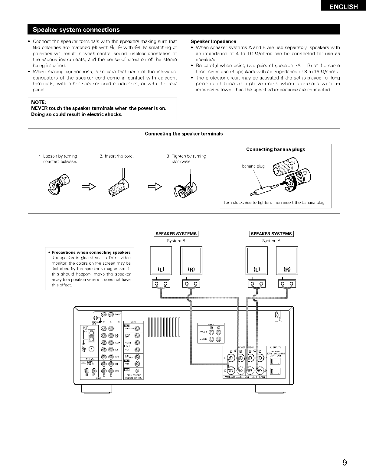
• Connect the speaker terminals with the speakers making sure that
like polarities are matched (_ with (_, e with e) Mismatching of
polarities will result in weak central sound, unclear orientation of
the vanous instruments, and the sense of direction of the stereo
being impaired
• When making connections, take care that none of the individual
conductors of the speaker cord come in contact with adjacent
terminals, with other speaker cord conductors, or with the rear
panel
NOTE:
NEVER touch the speaker terminals when the power is on.
Doing so could result in electric shocks.
Speaker Impedance
• When speaker systems A and B are use separately, speakers with
an impedance of 4 to I6 £_/ohms can be connected for use as
speakers
• Be careful when using two pairs of speakers {A + B) at the same
time, since use of speakers with an impedance of 8 to 16 £_/ohms
• The protector circuit may be activated if the set is played for long
periods of time at high volumes when speakers with an
impedance lower than the specified impedance are connected
1 Loosen by turning 2 Insert the cord
counterdockwise
Connecting the speaker terminals
=4>
3 Tighten by turning
clockwise
Connecting banana plugs
bananaplug
Turn clockwise to tighten, then insert the banana plug
•Precautions when connecting speakers
If a speaker is placed near a TV or video
monitor, the Colors on the screen may be
disturbed by the speaker's magnetism¸ If
this should happen, move the speaker
away to a position where it does not have
this effect¸
[SPEAKER SYSTEMS1ISPEAKERSYSTEMS ]
System B System A
m m
9
• This unit is equipped with a high-speed protection circuit. This circuit protects the internal circuitry from damage due to
large currents flowing if the speaker jacks are not completely connected or if an output is generated by a short circuit.
In such a case, the protection circuit will operate to cut off the output to the speakers. Should this happen, turn the
power off and check the speaker connections. Then turn the power on again. After muting for several seconds, the
receiver should be operating normally.
If the protection circuit is activated again even though there are no problems with the wiring or the ventilation around
the unit, switch off the power and contact a DENON service center.
• The protector circuit may be activated if the set is played for long periods of time at high volumes when speakers with
an impedance lower than the specified impedance (for example speakers with an impedance of lower than 4 £)/ohms)
are connected. If the protector circuit is activated, the speaker output is cut off. Turn off the set's power, wait for the set
to cool down, improve the ventilation around the set, then turn the power back on.
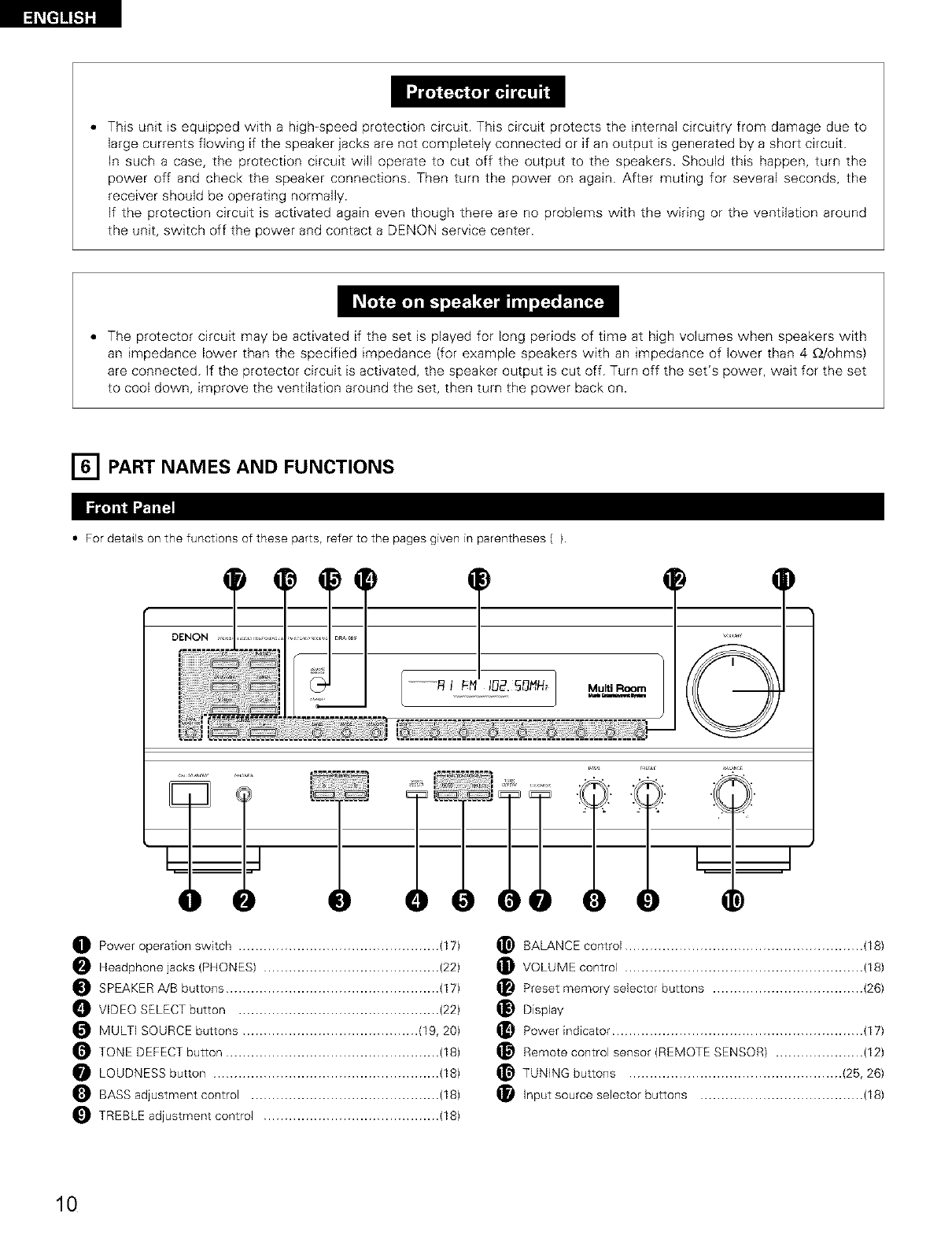
[] PART NAMES AND FUNCTIONS
•For details on the functions of these parts, refer to the pages given in parentheses ().
)T
................._ I_-_ I_2._NN_ Multi Room
......................................,.9. _. O._..O._..O. @. O. O. @ O
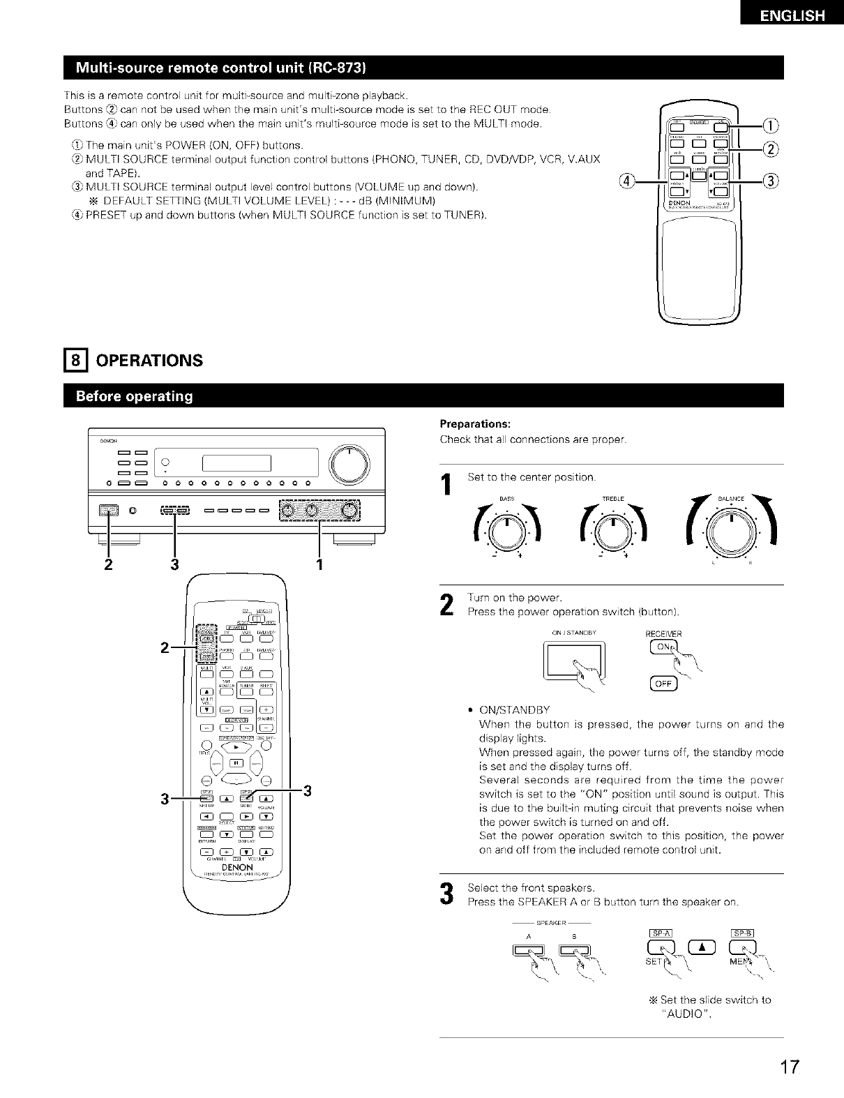
O Power operation switch ................................................ (17)
Headphone jacks (PHONES) .......................................... (22)
SPEAKER A/B buttons ................................................... (17)
VIDEO SELECT button ................................................ (22)
MULTI SOURCE buttons .......................................... (19, 20)
TONE DEFECT button ................................................... (18)
LOUDNESS button ...................................................... (18)
BASS adjustment control ............................................. (18)
TREBLE adjustment control .......................................... (18)
BALANCE control ......................................................... (18)
VOLUME control ......................................................... (18)
Preset memory selector buttons .................................... (26)
Display
Power indicator ............................................................ (17)
Remote control sensor (REMOTE SENSOR) ..................... (12)
TUNING buttons ................................................... (25, 26)
Input source selector buttons ....................................... (18)
10
[_[t]_t]][
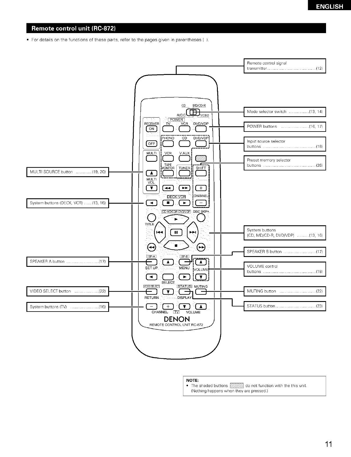
• For details on the functions of these parts, refer to the pages given in parentheses ().
I MULTI SOURCE button ............ {19, 20) t
I System buttons (DECK, VCR) {13, 16) I"
I SPEAKER A button ........................ (17) I
I VIDEO SELECT button .................. (22) I
I System buttons (TV) ..................... (16) I"
t tRrenms_itt_O:_rO[ : gr:a[ ...................... (12)
I Modese[ector switch ............... (13, 14) I
t POWER buttons ..................... (16,17} I
C:nS:Ttttt'tt11:.......................,18,
_::t::mtT?::?'it:t:...................(28_
t/_4%?C;;-%VO.DP/........./13,18/
,_1SPEAKERBbutton........................117/I
t Vu°ttL°:'?E?::K............................,18/
I MUTING button ........................... {22) I
Lt STATUS button .............................. {23) I
NOTE:
• The shaded buttons _ do not funct on with the this unit
(Nothing happens when they are pressed)
11
[] REMOTE CONTROL UNIT
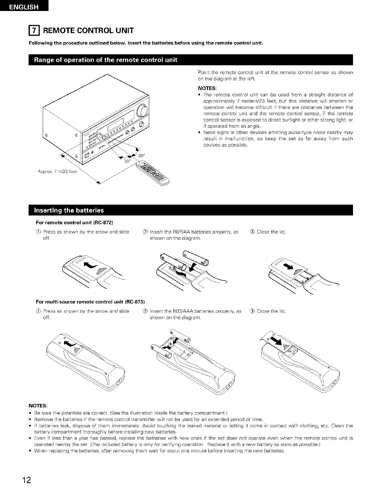
Following the procedure outlined below, insert the batteries before using the remote control unit.
Point the remote control unit at the remote control sensor as shown
on the diagram at the left
NOTES:
•The remote control unit can be used from a straight distance of
approximately 7 meters/23 feet, but this distance will shorten or
operation will become difficult if there are obstacles between the
remote control unit and the remote control sensor, if the remote
control sensor is exposed to direct sunlight or other strong light, or
if operated from an angle.
• Neon signs or other devices emitting pulse-type noise nearby may
result in malfunction, so keep the set as far away from such
devices as possible.
Approx 7 m/23 feet
For remote control unit (RC-872}
0_) Press as shown by the arrow and slide
off.
,:.2_Insert the R6P/AA batteries properly, as
shown on the diagram.
_3)Close the lid.
For multi-source remote control unit (RC-873)
0_) Press as shown by the arrow and slide (2) Insert the R03/AAA batteries properly, as
off. shown on the diagram.
_3)Close the lid.
NOTES:
•Be sure the polarities are correct. (See the illustration inside the battery compartment)
• Remove the batteries if the remote control transmitter will not be used for an extended period of time.
• If batteries leak, dispose of them immediately. Avoid touching the leaked material or letting it come in contact with clothing, etc Clean the
battery compartment thoroughly before installing new batteries
• Even if less than a year has passed, replace the batteries with new ones if the set does not operate even when the remote control unit ts
operated nearby the set (The included battery is only for verifying operation Replace it with a new battery as soon as possible)
• When replacing the batteries, after removing them wait for about one minute before inserting the new batteries
12
[_i_t]]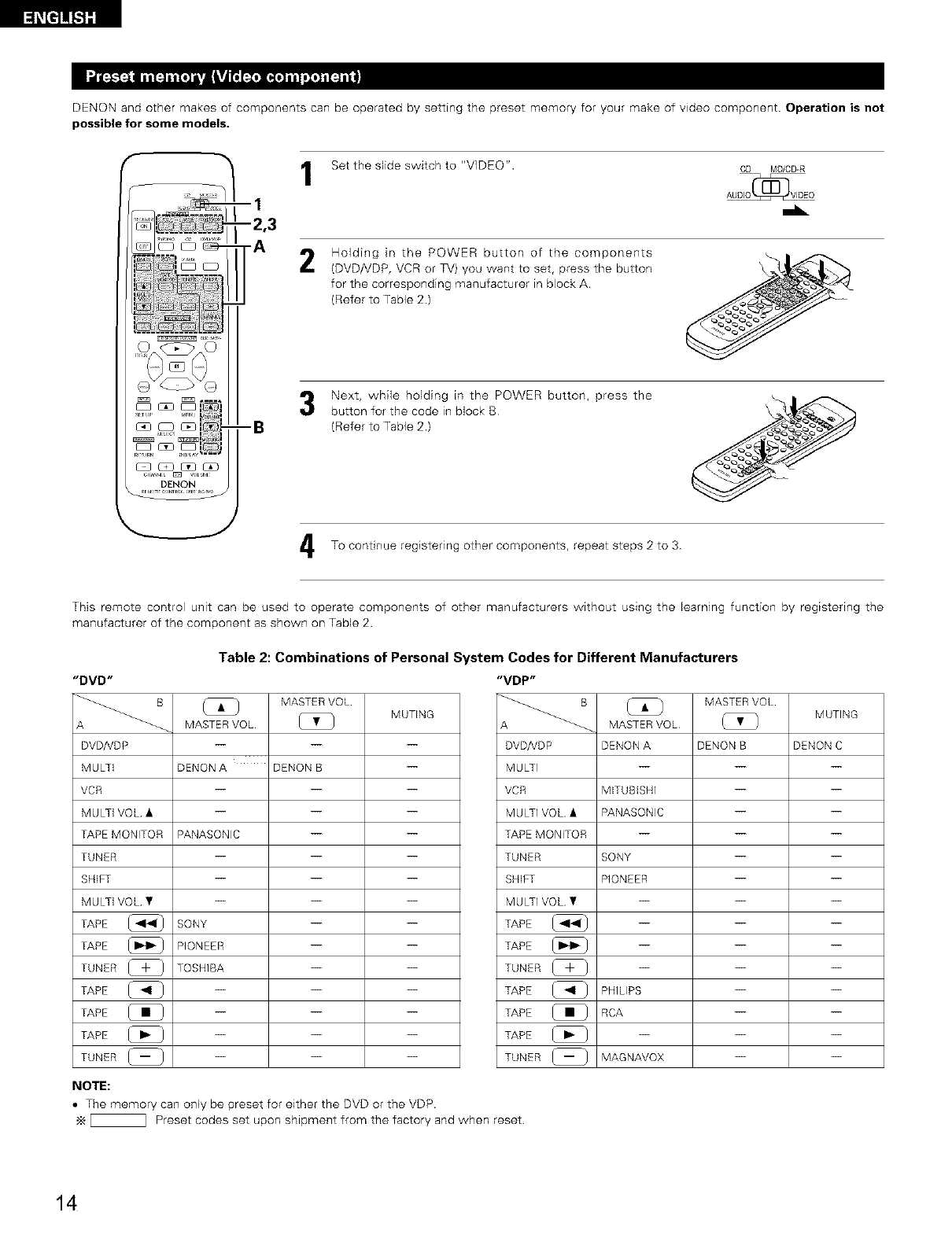
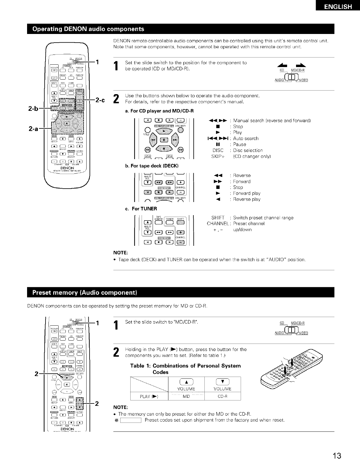
DENON and other makes of components can be operated by setting the preset memory for your make of video component. Operation is not
possible for some models.
--I
-2,3
-A
Set the slide switch to "VIDEO". CD MD/CD-R
..L
2Holding in the POWER button of the components
(DVD/VDP, VCR or TV) you want to set, press the button
for the corresponding manufacturer in block A.
(Refer to Table 2.)
Next, while holding in the POWER button, press the
button for the code in block B
(Refer to Table 2.)
To continue registering other components, repeat steps 2 to 3
This remote control unit can be used to operate components of other manufacturers without using the learning function by registering the
manufacturer of the component as shown on Table 2.
Table 2: Combinations of Personal System Codes for Different Manufacturers
"DVD"
A _
DVD/YDP
MULTi
VCR
MULTi VOL •
TAPEMONITOR
TUNER
SHIFT
MULTi VOL •
TAPE
TAPE
TUNER [_ }
TAPE @
TAPE
TAPE @
TUNER _
NOTE:
MASTER VOL
MUTING
MASTERVOL [_ }
DENON A DENON B --
PANASONIC -- --
SONY -- --
PIONEER -- --
TOSHIBA -- --
"VDP"
DVD/YDP
MULTI
VCR
MULTI VOL •
TAPE MONITOR
TUNER
SHIFT
MULTI VOL •
TAPE
TAPE
TUNER [_ _
TAPE @
TAPE
TAPE @
TUNER _
MASTER VOL
MUTING
MASTER VOL (_ }
DENON A DENON B DENON C
MITUBISHI -- --
PANASONIC -- --
SONY -- --
PIONEER -- --
PHILIPS -- --
RCA -- --
MAGNAVOX -- --
•The memory can only be preset for either the DVD or the VDP.
_ Preset codes set upon shipment from the factory and when reset
14
"VCR"
B
A _
DVD/VDP
MULTi
VCR
MULTi VOL •
TAPE MONITOR
TUNER
SHIFT
MULTi VOL •
TAPE
TAPE
TUNER _-_
TAPE
TAPE
TAPE
TUNER (_
MASTER VOL MUTING
MASTER VOL
HITACHI A HETACHI B
MITUBISHi A MITUBISHI B MITUBISHE C
PANASONIC A PANASONIC B PANASONIC C
JVC (VICTOR) A JVC (VICTOR) B JVC (VICTOR) C
SONY A SONY B SONY C
PIONEER -- --
TOSHIBA A TOSHIBA B
SANYO A SANYO B --
SHARP A SHARP B --
NEC A NEG B NEC C
PHILIPS A PHILIPS B PHLIPS C
RCA A RCA B --
GENERAL GENERAL
ELECTREC A ELECTRIC B
MAGNAVOX A MAGNAVOX B MAGNAVOX C
"TV"
DVD/VDP
MULTI
VCR
MULTI VOL •
TAPE MONITOR
TUNER
SHIFT
MULTi VOL •
TAPE
TAPE
TUNER [_
TAPE
TAPE
TAPE
TUNER (_
MASTER VOL MUTING
MASTER VOL
HITACHI -- --
MITUBISHI A MITUBISHI B
PANASONIC A PANASONIC B
JVC (VICTOR) -- --
SONY -- --
PIONEER -- --
TOSHIBA -- --
SANYO -- --
SHARP -- --
NEC -- --
PHILIPS -- --
RCA -- --
GENERAL GENERAL __
ELECTRIC A ELECTRIC B
MAGNAVOX -- --
_ Preset codes set upon shipment from the factory and when reset
NOTES:
• The signals for the pressed buttons are emitted while setting the preset memory To avoid accidental operation, cover the remote
control unit's transmitting window while setting the preset memory.
• Some models and years of manufacture of components of the manufacturers listed on Table 2 cannot be used
• The unit is equipped with several types of remote control codes which depend on the manufacturer. If there is no operation when set to
A, please change the setting to B or C and try again
15
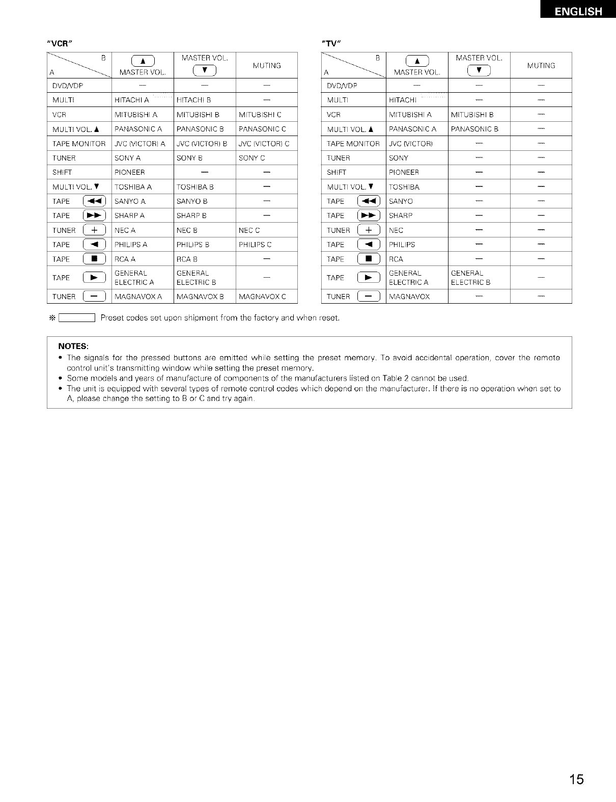
1Set the slide switch to "VIDEO". CD MD/CD-R
AUDIO(_ VIDEO
Operate the video component.
• For details, refer to the component's operating instructions.
•_ Some models cannot be operated with this remote control unit.
a. For DVD player
i_l_Tul_ U_HA¥
POWER : Power on/off
• : Stop
I_ : Play
1_1_1,11_1_1 : Auto search (cue)
n : Pause
TITLE : Call out title
MENU : Call out menu
DISPLAY : Switch display
SET UP : DVD setup
RETURN : Menu return
•, • : Cursor up/down
_1, I_ : Cursor left/right
SELECT : Enter setting
DISC SKIP + : Disc selection
NOTE:
Some manufacturers use different names for the DVD
remote control buttons, so also refer to the instructions
on remote control for that component.
c, For video deck (VCR}
--1
--2
-2-c
b. For video disc player (VDP} d. For TV
POWER : Power on/off
414,1_1_ : Manual search
(reverse and forward)
• : Stop
I_ : Play
144,11_J_ : Auto search (cue)
II : Pause
[_ GD I_1 G3
(:3D(:_ (2El I2D
[Z3 (2D (3D GD
POWER : Power on/off
4_11,1_1 _ : Manual search
(reverse and forward)
• : Stop
I_ : Play
CHANNEL: Switch channel
+,-
O^_E:::>^O
00 0o
POWER : Power on/off
VOLUME : Volume
• , ¥ up/down
CHANNEL: Switch channel
+ ,-
NOTE:
The TV can be operated when the
switch is at any position
16
[_i_t]]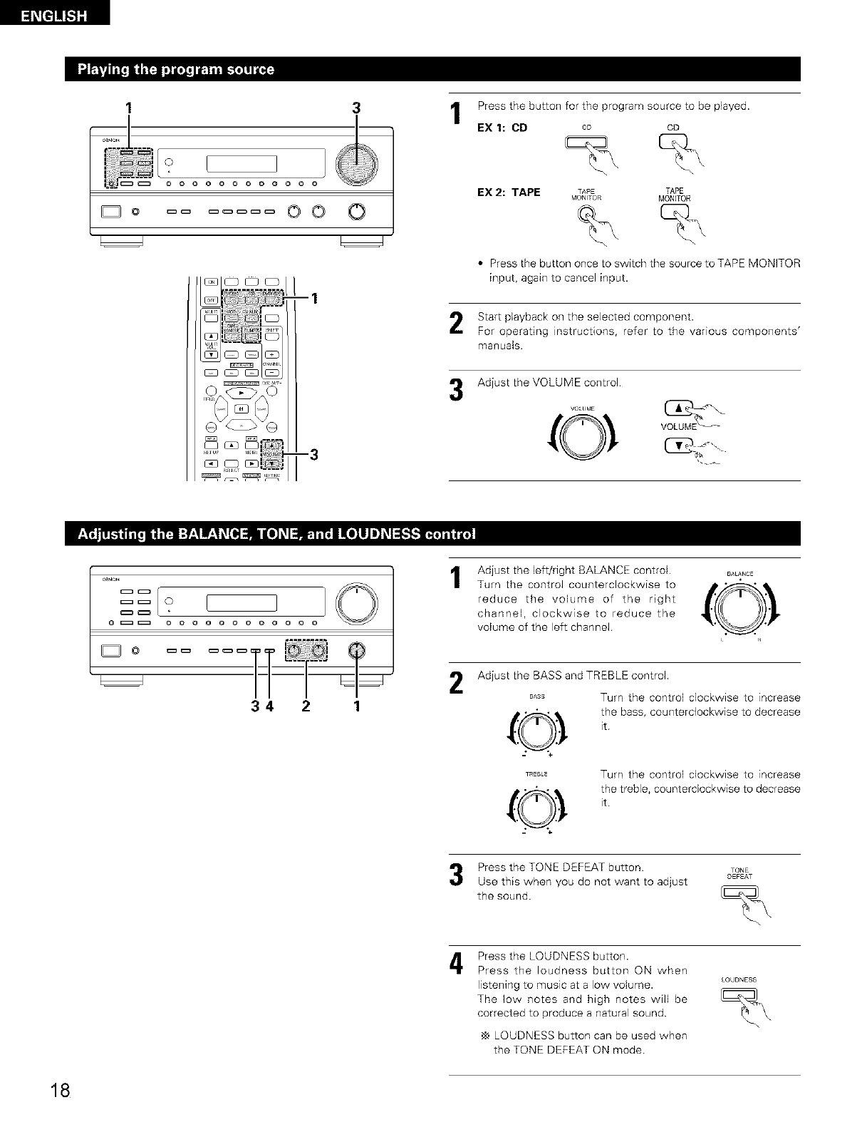
_t]1![.1][
1 3
r%/ i I
_o O0 0
--1
Press the button for the program source to be played.
EX 1: CD co cD
EX2: TAPE TAPE TAPE
MONI,OR MOHITOR
• Press the button once to switch the source to TAPE MONKOR
input, again to cancelinput.
Start playback on the selected component.
For operating instructions, refer to the various components'
manuals.
-3
Adjust the VOLUME control
VOLUb E
_ O
o _ o o o o o o o o o o
34 2 1
1
2
Adjust the left/right BALANCE control BJ,L^NCE
Turn the contro/ counterclockwise to _"O, _
reduce the volume of the right
channel, clockwise to reduce the
volume of the left channel.
Adjust the BASS and TREBLE control.
BASS Turn the control clockwise to _ncrease
the bass, counterclockwise to decrease
it
Turn the control clockwise to increase
the treble, counterclockwise to decrease
it
Press the TONE DEFEAT button
Use this when you do not want to adjust
the sound.
TONE
OEFEAT
4Press the LOUDNESS button.
Press the loudness button ON when
listening to music at a low volume.
The low notes and high notes will be
corrected to produce a natural sound.
,_ LOUDNESS button can be used when
the TONE DEFEAT ON mode
18
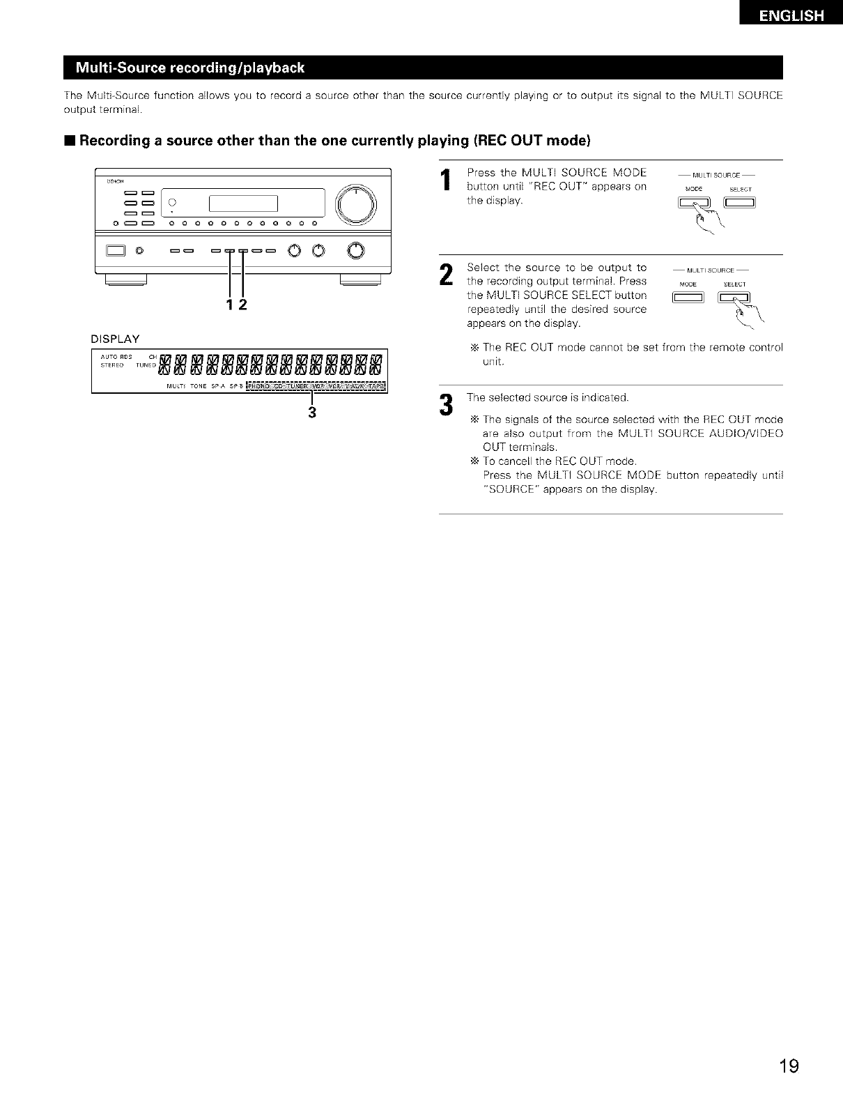
The Mulg-Source funcgon allows you to record a source other than the source currently playing or to output its signal to the MULTI SOURCE
output terminal
•Recording a source other than the one currently playing (REC OUT mode)
D_ON I I 10
o_ o o o o ooo o o o
_:_° _ =T_l_ OO _O
12
DISPLAY
MU_T TONE SPA SP_
a
Press the MULTI SOURCE MODE
button until "REC OUT" appears on
the display
MULT_SOURCE
_ODE SELECT
2Select the source to be output to MULTISOURCE
the recording output terminal. Press MODE EECT
the MULTI SOURCE SELECT button _
repeatedly ungl the desired source
appears on the display.
The REC OUT mode cannot be set from the remote control
unit
3The selected source is indicated
The signals of the source selected with the REC OUT mode
are also output from the MULTI SOURCE AUDIO/VIDEO
OUT terminals.
,_ To cancell the REC OUT mode.
Press the MULTI SOURCE MODE button repeatedly until
"SOURCE" appears on the display
19
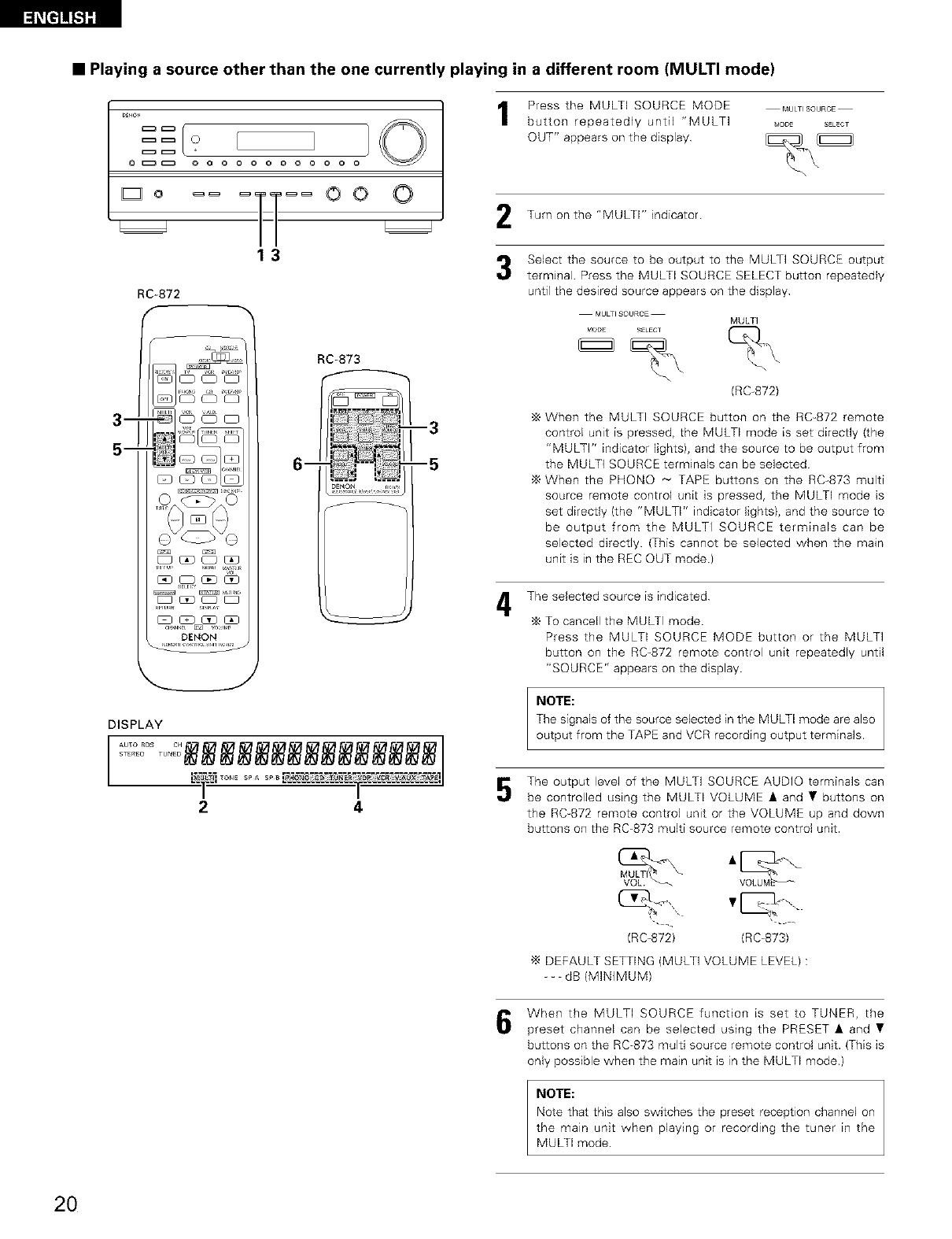
•Playing a source other than the one currently playing in a different room (MULTI mode)
i}O
oC_ oo o o o o o o o o
H 2
3
m
5--
RC-872
_ c_ oq
DENON
RC-873
m
--3
--5
DE_Ot4 r,,.,,,
DISPLAY
STEREO....... TUN EC_ _ _ ___
2 4
Press the MULTi SOURCE MODE
button repeatedly until "MULTI
OUT" appears on the display
MULT_SOURCE
_ODE SELECT
Turn on the "MULTI" indicator
Select the source to be output to the MULTI SOURCE output
terminal Press the MULTi SOURCE SELECT button repeatedly
until the desired source appears on the display
MULTI SOURCE MULTI
MODE _ELECT
(RC-872)
When the MULTI SOURCE button on the RC-872 remote
control unit is pressed, the MULTI mode is set directly (the
"MULTi" indicator lights), and the source to be output from
the MULTi SOURCE terminals can be selected
When the PHONO _ TAPE buttons on the RC-873 multi
source remote control unit is pressed, the MULTI mode is
set directly (the "MULTI" indicator lights), and the source to
be output from the MULTI SOURCE terminals can be
selected directly (This cannot be selected when the mare
unit is in the REC OUT mode.)
The selected source is indicated
To cancell the MULTi mode
Press the MULTI SOURCE MODE button or the MULTI
button on the RC-872 remote control unit repeatedly until
"SOURCE" appears on the display
NOTE:
The signals of the source selected in the MULTI mode are also
output from the TAPE and VCR recording output terminals.
The output level of the MULTi SOURCE AUDIO terminals can
be controlled using the MULTI VOLUME • and • buttons on
the RC-872 remote control unit or the VOLUME up and down
buttons on the RC-873 multi source remote control unit.
(RC-872) (RC-873)
DEFAULT SETTING (MULTi VOLUME LEVEL):
--- dB (MINIMUM)
When the MULTi SOURCE function is set to TUNER, the
preset channel can be selected using the PRESET • and •
buttons on the RC873 multi source remote control unit. (This is
only possible when the main unit is in the MULTI mode.)
NOTE:
Note that this also switches the preset reception channel on
the main unit when playing or recording the tuner in the
MULTI mode.
20
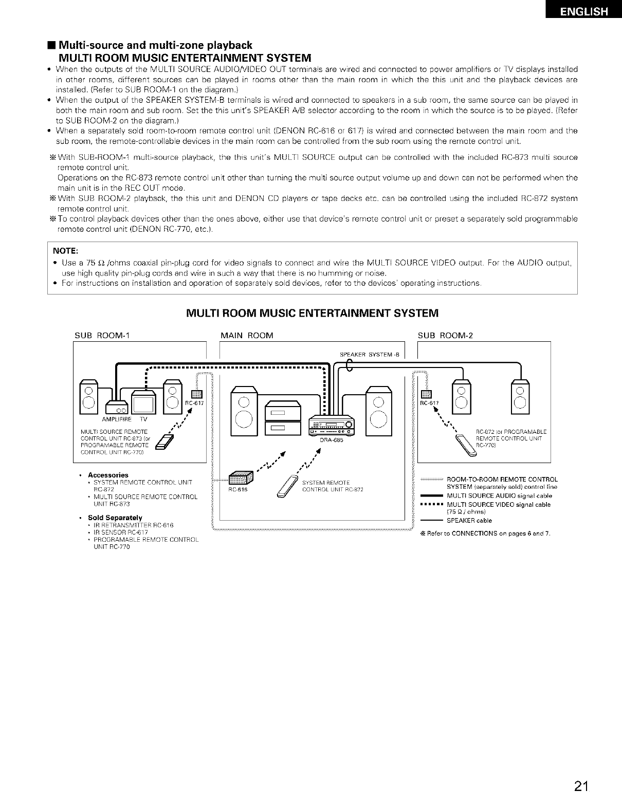
•Multi-source and multi-zone playback
MULTI ROOM MUSIC ENTERTAINMENT SYSTEM
•When the outputs of the MULTI SOURCE AUDIO/VIDEO OUT terminals are wired and connected to power amplifiers or TV displays installed
in other rooms, different sources can be played in rooms other than the main room in which the this unit and the playback devices are
installed. (Refer to SUB ROOM-1 on the diagram.)
• When the output of the SPEAKER SYSTEM_B terminals is wired and connected to speakers in a sub room, the same source can be played in
both the main room and sub room. Set the this unit's SPEAKER A/B selector according to the room in which the source is to be played. (Refer
to SUB ROOM-2 on the diagram}
• When a separately sold room-to-room remote control unit (DENON RC-616 or 617) is wired and connected between the main room and the
sub room, the remote-controllable devices in the main room can be controlled from the sub room using the remote control unit
With SUB-ROOM4 multi-source playback, the this unit's MULTI SOURCE output can be controlled with the included RC-873 multi source
remote control unit
Operations on the RC-873 remote control unit other than turning the multi source output volume up and down can not be performed when the
main unit is in the REC OUT mode.
_With SUB ROOM-2 playback, the this unit and DENON CD players or tape decks etc. can be controlled using the included RC-872 system
remote control unit
'_ To control playback devices other than the ones above, either use that device's remote control unit or preset a separately sold programmable
remote control unit (DENON RC-770, etc.)
NOTE:
• Use a 75 _2/ohms coaxial pin-plug cord for video signals to connect and wire the MULTI SOURCE VIDEO output For the AUDIO output,
use high quality pin-plug cords and wire in such a way that there is no humming or noise.
• For instructions on installation and operation of separately sold devices, refer to the devices' operating instructions
MULTI ROOM MUSIC ENTERTAINMENT SYSTEM
SUB ROOM-1 MAIN ROOM SUB ROOM-2
AMPLIFIRE q_/ ,,_"
MULTI SOURCE REMOTE _
CONTROL UNIT RC823 {or
PROGRAMABLE REMOTE
CONTROL UNIT RC 710)
•Accessoi'ies
• SYSTEM REMOTE CONTROL UNIT
RC 872
• MULTI SOURCE REMOTE CONTROL
UNIT RC 873
•Sold Separately
• R RETRANSM]TTER RC 616
• R SENSOR RC 617
• PRQGRAMABLE REMOTE CONTROL
UNIT RC 770
SPEAKER SYSTEMB I
DRA685
4
SYSTEM REMOTE
RC616 CONTROL UNIT RC-872
• RC872 1o4 PROGRAMABLE
ROOM TO-ROOM REMOTE CONTROL
SYSTEM Iseparately sold) control ITne
MULTI SOURCE AUDIO s_gnal cable
====== MULTI SOURCE VIDEO signal cable
; 175 _ /ohms)
-- SPEAKER cable
Refer to CONNECTIONS on pages 6 and 7.
21
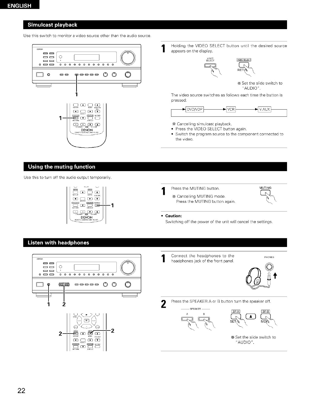
Use this switch to monitor a video source other than the audio source.
_ O
@_ o o o o o o o o o o
moo
1
1- _ _©
Holding the VIDEO SELECT button until the desired source
appears on the display.
VlOEO
SELECr
Set the slide switch to
"AUDIO"
The video source switches as follows each time the button is
pressed:
Cancelling simulcast playback.
•Press the VIDEO SELECT button again
•Switch the program source to the component connected to
the video.
Use this to turn off the audio output temporarily.
-1
Press the MUTING button.
Cancelling MUTING mode
Press the MUTING button again
MUTING
• Caution:
Switching off the power of the unit will cancel the settings
_ O
°T "°i oo o
12
2-__ -2
Connect the headphones to the
headphones lack of the front panel
2
PHONES
Press the SPEAKER A or B button turn the speaker off.
,_ Set the slide switch to
"AUDIO".
22
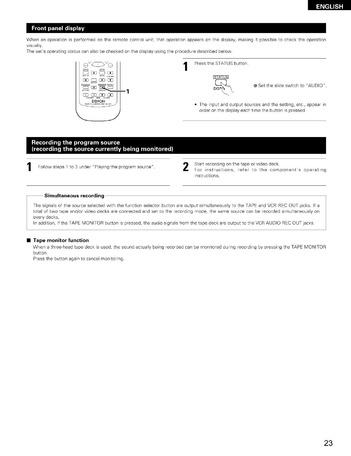
When an operation is performed on the remote control unit, that operation appears on the display, making it possible to check the operation
visually
The set's operating status can also be checked on the display using the procedure described below.
E_2UZ_u_l_c
DENON
1Press the STATUS button.
,_ Set the slide switch to "AUDIO'.
• The input and output sources and the setting, etc., appear in
order on the display each time the button is pressed
Follow steps 1 to 3 under Playing the program source"
JJ
Simultaneous recording
Start recording on the tape or video deck
For instructions, refer to the component's operating
instructions.
The signals of the source selected with the function selector button are output simultaneously to the TAPE and VCR REC OUT jacks. If a
total of two tape and/or video decks are connected and set to the recording mode, the same source can be recorded simultaneously on
every decks.
In addition, if the TAPE MONITOR button is pressed, the audio signals from the tape deck are output to the VCR AUDIO REC OUT jacks
•Tape monitor function
When a three-head tape deck is used, the sound actually being recorded can be monitored during recording by pressing the TAPE MONITOR
button
Press the button again to cancel monitoring.
23
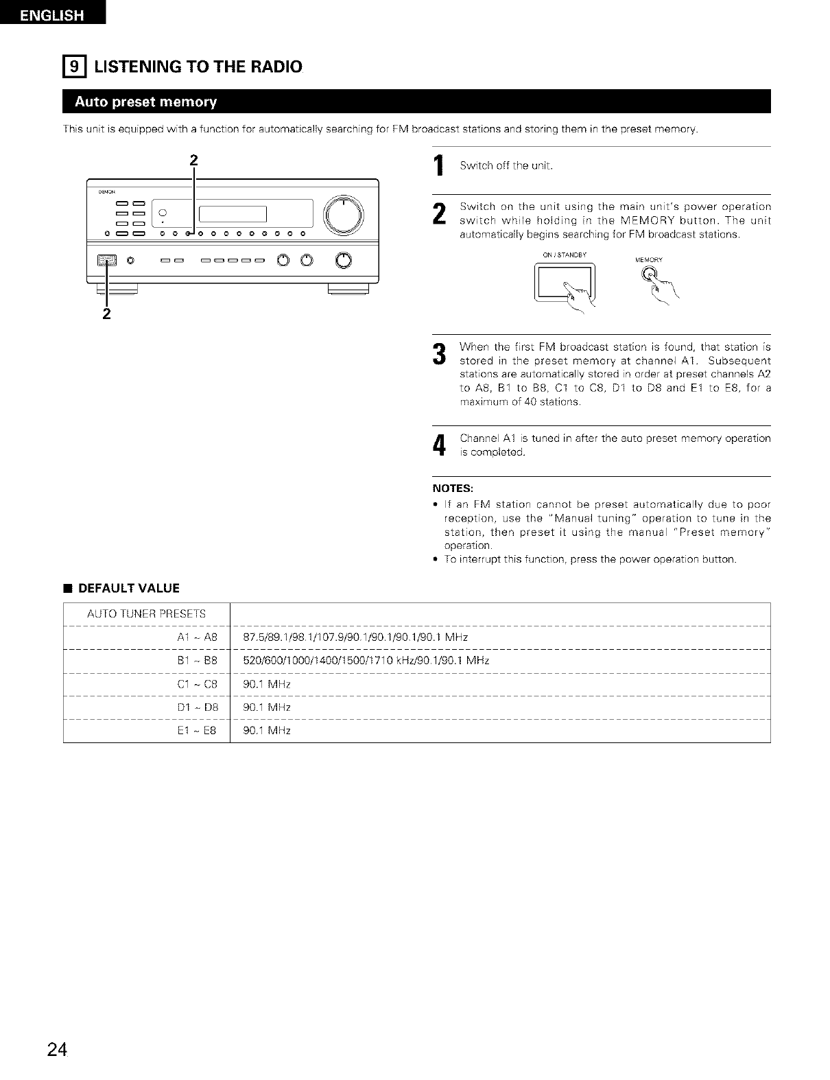
[] LISTENING TO THE RADIO
This unit is equipped with a function for automatically searching for FM broadcast stations and storing them in the preset memory.
21
..... J! i©
o_ o oooo ooo
oo O
2
Switch off the unit.
Switch on the unit using the main unit's power operation
switch while holding in the MEMORY button. The unit
automatically begins searching for FM broadcast stations.
ON /STANDBY
When the first FM broadcast station is found, that station is
stored in the preset memory at channel AI Subsequent
stations are automatically stored in order at preset channels A2
to AS, B1 to BS, C1 to C8, D1 to D8 and E1 to E8, for a
maximum of 40 stations
Channel A1 is tuned in after the auto preset memory operation
is completed
•DEFAULT VALUE
AUTO TUNER PRESETS
A1 - A8
B1 - B8
C1 _ C8
D1 _ D8
E1 - E8
NOTES:
• If an FM station cannot be preset automatically due to poor
reception, use the "Manual tuning" operation to tune in the
station, then preset it using the manual "Preset memory"
operation.
• To interrupt this function, press the power operation button.
875/89.1/981/107.9/901/90.1/901/90.1 MHz
520/600/1000/1400/1500/1710 kHz/90 1/90.1 MHz
901 MHz
901 MHz
901 MHz
24
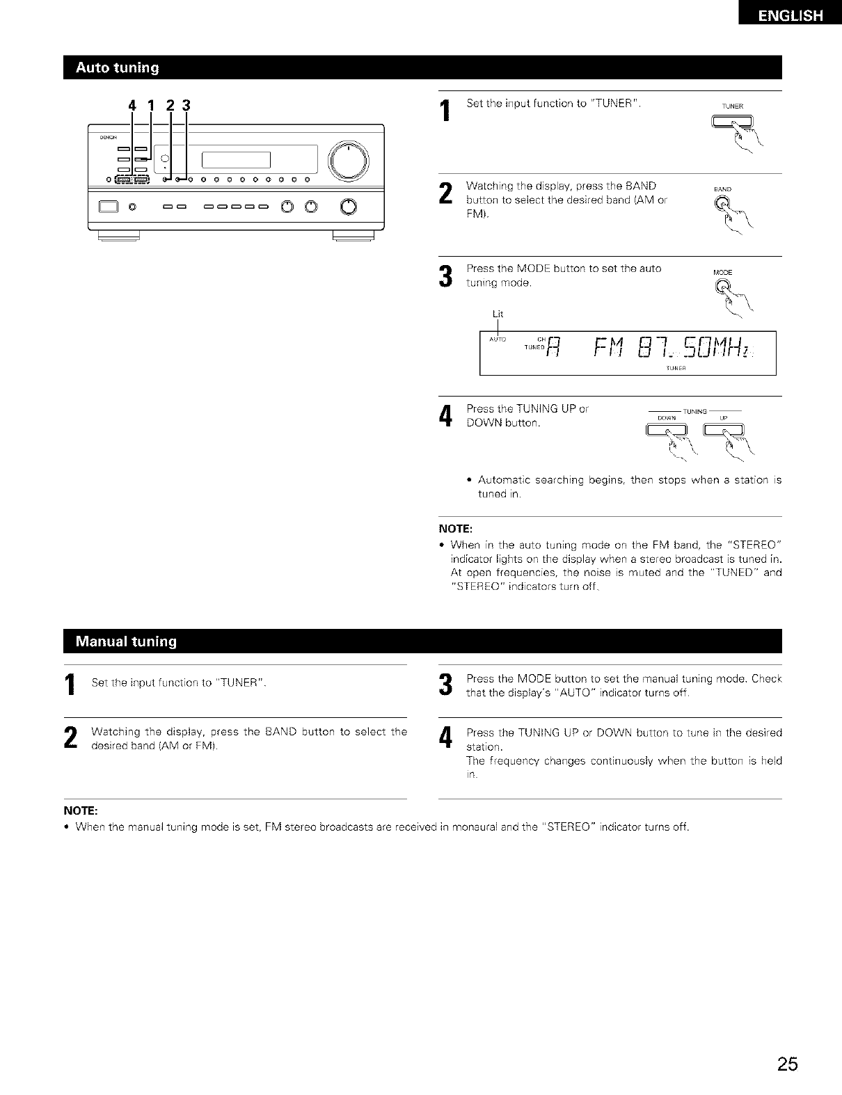
4123
oC_-_@,.) o o o o oooo
©0 ©
Set the input function to "TUNER" TUNER
Watching the display, press the BAND BA_,D
button tO select the desired band (AM or
FM) %
Press the MODE button to set the auto MODE
tuningLitmode. _._
AULO °" -M "-I _el- _A
....RF-,, B,, ,F/;
TUNER
Press the TUNING UP or TUNING
DOWN button, bow. u_
•Automatic searching begins, then stops when a station is
tuned in.
NOTE:
•When in the auto tuning mode on the FM band, the "STEREO"
indicator lights on the display when a stereo broadcast is tuned in.
At open frequencies, the noise is muted and the "TUNED" and
"STEREO" indicators turn off
Set the input function to "TUNER"
Watching the display, press the BAND button to select the
desired band (AM or FM).
Press the MODE button to set the manual tuning mode Check
that the display's "AUTO" indicator turns off
Press the TUNING UP or DOWN button to tune in the desired
station.
The frequency changes continuously when the button is held
in
NOTE:
•When the manual tuning mode is set, FM stereo broadcasts are received in monaural and the "STEREO" indicator turns off.
25
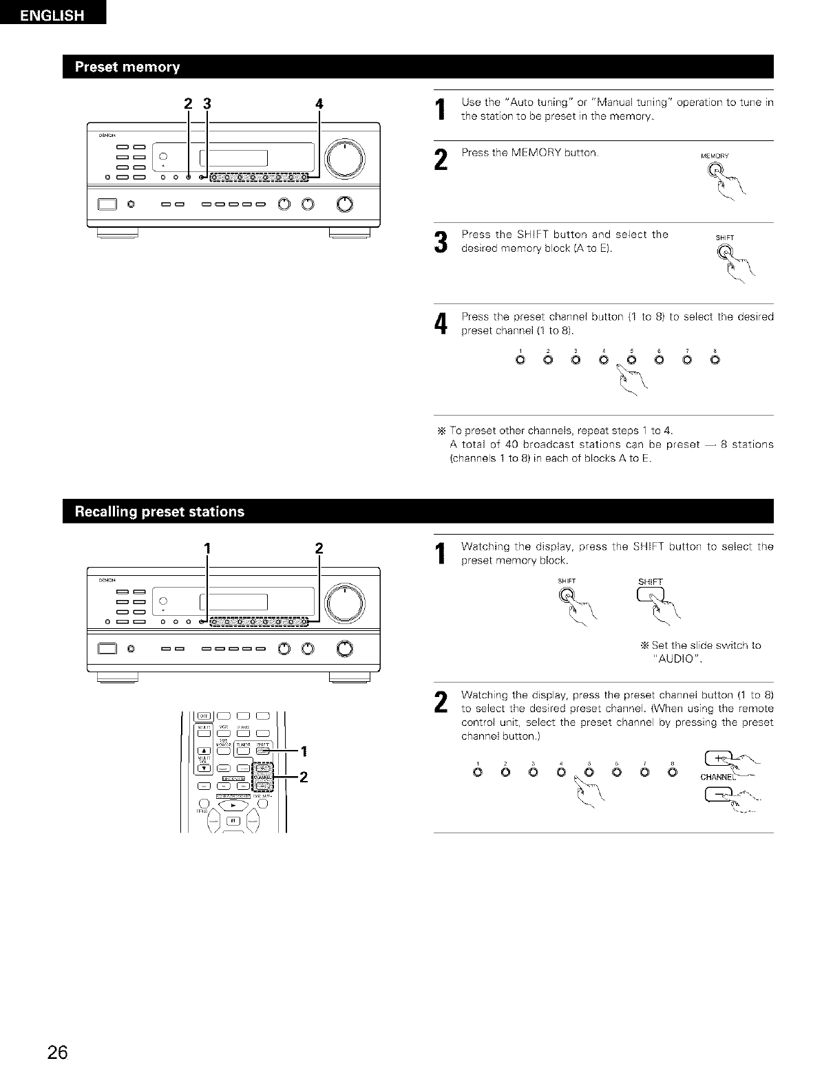
_t]1![.1][
4t Use the "Auto tuning" or "Manual tuning" operation to tune in
lthe station to be preset in the memory
23
== ?[![_
_o oo O Press the MEMORY button MEmor_
Press the SHIFT button and select the
desired memory block (A to E).
SHIFT
Press the preset channel button (1 to 8) to select the desired
preset channel (1 to 8).
666_66
To preset other channels, repeat steps 1 to 4.
A total of 40 broadcast stations can be preset -- 8 stations
(channels 1 to 8) in each of blocks A to E.
2
] 1
D O oo O
-1
-2
Watching the display, press the SHIFT button to select the
preset memory block.
2
SHIFT SHIFT
Set the slide switch to
"AUDIO"
Watching the display, press the preset channel button (1 to 8)
to select the desired preset channel. (When using the remote
control unit, select the preset channel by pressing the preset
channel button.)
8
26
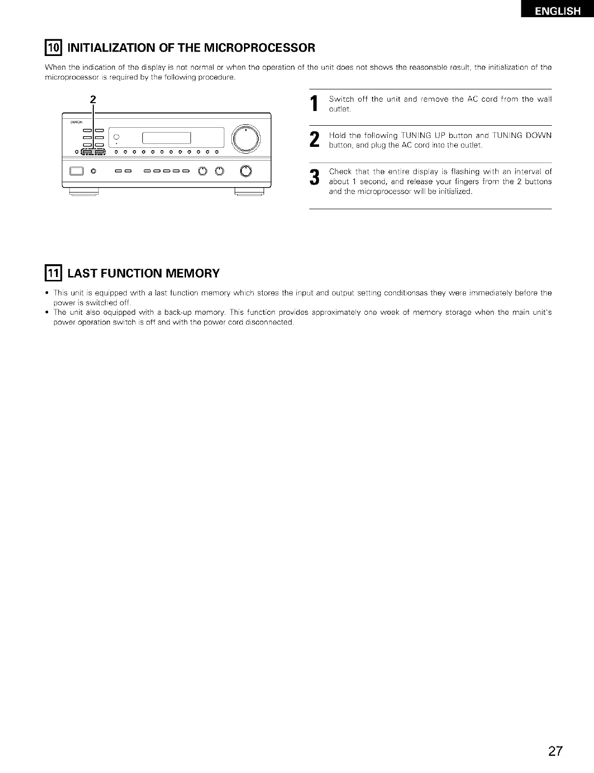
[] INITIALIZATION OF THE MICROPROCESSOR
When the indication of the display is not normal or when the operation of the unit does not shows the reasonable result, the initialization of the
microprocessor is required by the following procedure
2
o C_:_-_::_..'_o o o o o o o o o o
Do OO O
Switch off the unit and remove the AC cord from the wall
out]et.
Hold the following TUNING UP button and TUNING DOWN
button, and plug the AC cord into the outlet
Check that the entire display is flashing with an interval of
about 1 second, and release your fingers from the 2 buttons
and the microprocessor will be initialized.
r_ LAST FUNCTION MEMORY
•This unit is equipped with a last function memory which stores the input and output setting conditionsas they were immediately before the
power is switched off
• The unit also equipped with a back-up memory This function provides approximately one week of memory storage when the main unit's
power operation switch is off and with the power cord disconnected.
27
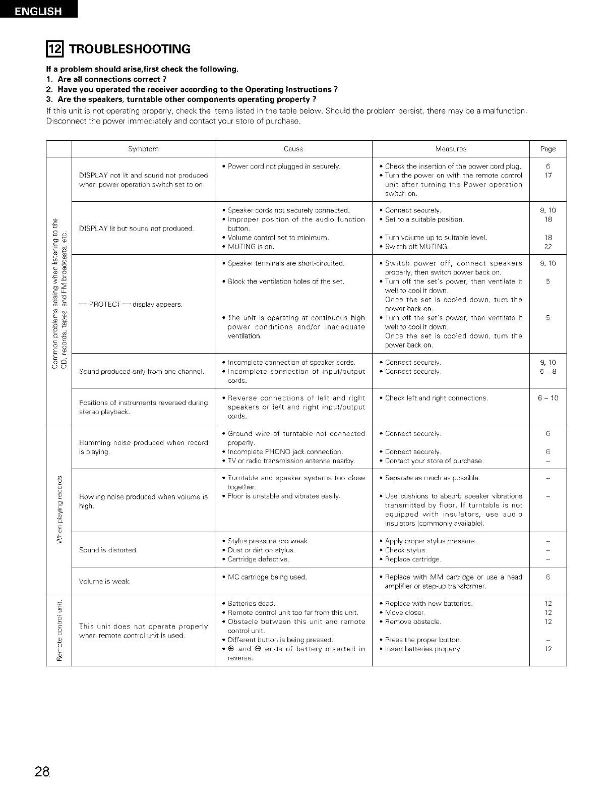
[] TROUBLESHOOTING
If a problem should arise,first check the following.
1. Are all connections correct ?
2. Have you operated the receiver according to the Operating Instructions ?
3. Are the speakers, turntable other components operating property ?
If this unit is not operating properly, check the items listed in the table below. Should the problem persist, there may be a malfunction
Disconnect the power immediately and contact your store of purchase.
Symptom Cause Measures Page
• Power cord not plugged in securely *Check the insertion of the power cord plug 6
DISPLAY not lit and sound not produced *Turn the poweE on with the remote control 17
when power operat on switch set to on unit after turning the Power operat on
switch on
• Speaker cords not securely connected • Connect securely
._ • Improper position of the audio function • Set to a suitable position
DISPLAY lit but sound not produced button
o_ • Volume control set to minimum • Turn volume up to suitable level
_ • MUTING is on • Switch off MUTING
• Speaker terminals are shon_circuJted
s
r_ _ -- PROTECT -- display appears
• Block the vent lat on holes of the set
® Cz
o_
(D (D
• The unt is operating at continuous high
power conditions and/or inadequate
ventilation
• Swtch power off, connect speakers
properly, then switch power back on
• Turn off the set's power, the_l ve_ltilate it
well to cool it down
O_lCe the set is cooled down, turn the
power back on
• Turn off the set's power, the_l ve_ltilate it
well to cool it down
O_lCe the set is cooled down, turn the
power back on
9,10
18
18
22
9,10
5
• I_lcomplete CO_lnection of speaker cords • Connect securely 9, 10
Sound produced only from one channel • Incomplete connection of input/output • Connect securely 6 _ 8
corUs
• Reverse connectons of left and right • Checkleftand right connectons 6 10
Positions of instruments reversed during speakers or left and right input/output
stereo playback cords
• Ground wire of turntable not connected • Connect securely 6
Humming noise produced when record properly
is playing • incomplete PHONO }ack connection • Connect securely 6
• TM or radio transmission antenna nearby • Contact your store of purchase
• Turntable and speaker systems too close • Separate as much as possible
together
® Howling noise produced when volume is Floor is unstable and vibrate° easily • Use cushions to absorb speaker vibrations
high transmitted by floor If turntable is not
equ pped with insulators, use audio
insulators (commonly available)
• Stylus pressure too weak • Apply proper stylus pressure
Sound is distorted • Dust or dirt on stylus • Check stylus
• Car[ridge defective • Replace cartridge
Volume is weak • MC cartridge being used • Replace with MM cartridge or use a head 6
amplifier or step-u b transformer
• Batteries dead • Replace with new battedeo_ 12
• Remote control unit too far from this unit • Move closer 12
• Obstacle between this unit and remote • Remove obstacle 12
This unt does not operate properly control unit
when remote control unit is used Different button is being presoed • Press the proper button
• G and O ends of battery inserted in Insert battedeo properly 12
reverse
28
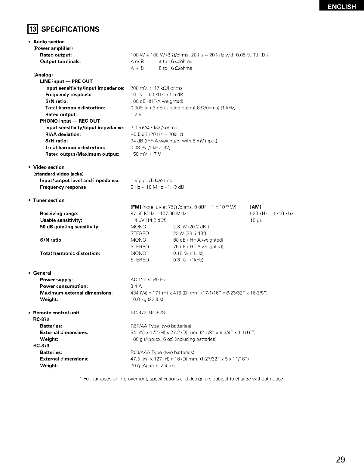
[] SPECIFICATIONS
•Audio section
(Power amplifier)
Rated output:
Output terminals:
(Analog}
LINE input -- PRE OUT
Input sensitivity/input impedance:
Frequency response:
S/N ratio:
Total harmonic distortion:
Rated output:
PHONO input -- REC OUT
Input sensitivity/input impedance:
RIAA deviation:
S/N ratio:
Total harmonic distortion:
Rated output/Maximum output:
100 W + 100 W (8 _/ohms, 20 Hz - 20 kHz with 0.05 % T H.D.)
A or B 4 to 16 _/ohms
A + B 8to 16_/ohms
200 mV /47 k_/kohms
10 Hz- 50 kHz: +1 5 dB
100 dB (IHFA weighted)
0009 % (_3dB at rated output,8 _/ohms) (1 kHz)
12 V
30 mV/47 k_/kohms
+0.5 dB (20 Hz - 20kHz)
74 dB (]HF-A weighted, with 5 mV input)
003 % (1 kHz, 3V)
150mV /7V
•Video section
(standard video jacks}
Input/output level and impedance:
Frequency response:
1 V p-p, 75 _/ohms
5Hz_ 10 MHz +1,-3 dB
•Tuner section
Receiving range:
Usable sensitivity:
50 dB quieting sensitivity:
SIN ratio:
Total harmonic distortion:
[FM] (note: pV at 75_/ohms, 0 dBf -1 x 10 _' W)
87.50 MHz _ 107.90 MHz
1 4 #V(142 dBf)
MONO 28 pV(202 dBf)
STEREO 231iV (38.5 dBf)
MONO 80 dB (IHF-A weighted)
STEREO 75 dB (IHF-A weighted)
MONO 015 % (lkHz)
STEREO 03% (lkHz)
[AM]
520 kHz _ 1710 kHz
18 #V
•General
Power supply:
Power consumption:
Maximum external dimensions:
Weight:
AC I20V, 60 Hz
34 A
434 (W) x 171 /H) x 416 (D) mm (17q/16" x 6_23/32" x 16-3/8")
10.0 kg (22 Ibs)
•Remote control unit
RC-872
Batteries:
External dimensions:
Weight:
RC-873
Batteries:
External dimensions:
Weight:
RC-872, RC-873
R6P/AA Type (two batteries)
54 (W) x I72 (H) x 27.2 (D) mm (2q/8" x 6-3/4" x lq/16")
100 g (Approx 6 oz) (incLuding batteries)
R03/AAA Type (two batteries)
47.5 (W) x 127 (H) x 18 (D) mm (%27/32" x 5 x 11/16")
70 g (Approx. 2.4 oz)
* For purposes of improvement, specifications and design are subject to change without notice
29
•INTRODUCTION
Nous vous remercions d'avoir choisi le r_cepteur radio FM _AM ster6o DENON.
Ce remarquable composant a 6t6 fabriqu6 pour assurer une reproduction haute fid61it_ remarquable de vos sources musicales favorites
Ce produit 6rant 6quip_ d'une immense foule de caracteristiques, nous vous recommandons avant de commencer I'installation et I'utilisation de
I'appareil de bien lire le contenu de ce manuel avant de proceder.
TABLE DES MATIERES
Avant L'utilisation ............................................................ 30
Precautions D'installation ................................................ 31
Precautions de Manipulation ............................................. 31
Caracteristiques ............................................................ 31
Connexions ............................................................ 32-36
Nomenclature et Fonctions .......................................... 36, 37
Unit6 de Tel6commande ............................................. 38-43
Op6rations ............................................................... 43-49
Ecouter de la Radio ................................................... 50-52
El Initialisation du Microprocesseur ....................................... 53
Memoire de Derni_re Fonction ....................................... 53
Depistage des Pannes ................................................... 54
El Specifications ............................................................... 55
•ACCESSOIRES
Verifier que les articles suivants sont inclus darts le carton en plus de I'unite principale:
0) Mode d'emploi ............................................................ 1
(2) Certificat de garantie ...................................................... 1
(3) Liste des centres d'entretien .......................................... 1
(4) T616commande (RC-872) ................................................ 1
(RC-873} ................................................ 1
(5) Piles (R6P/AA) ......................................................... 2
(R03/AAA) ...................................................... 2
(6} Antenne_cadre AM ......................................................... 1
(7} Antenne interieure FM ................................................... 1
@
%%
(RC_872) (RC_873)
® ®
©®
[] AVANT L'UTILISATION
Faire attention au points suivants avant d'utiliser cet appareil:
•D_placement del'appareil
Pour 6viter des court-circuits ou des fils endommages dans les
c_bles de connexion, toujours debrancher le cordon d'alimentation,
et d_connecter les c_bles de connexion entre tous les autres
composants audio Iors du d6placement de I'appareil.
•Avant de mettre sous tension
V6rifier une nouvelle fois si toutes les connexions sont bonnes et
s'il n'y a pas de probl_mes avec les c_bles de connexion. Toujours
placer I'interrupteur de raise sous tension en position d'attente
avant de connecter et de deconnecter les c_bles de connexion.
•Ranger ces instructions dans un endroit s_r
Apr_s les avoir lues, ranger ces instructions en m6me temps que
la garantie darts un endroit s0r.
•Noter que les illustrations de ces instructions peuvent varier
de I'appareil actuel dans un but d'explication.
30
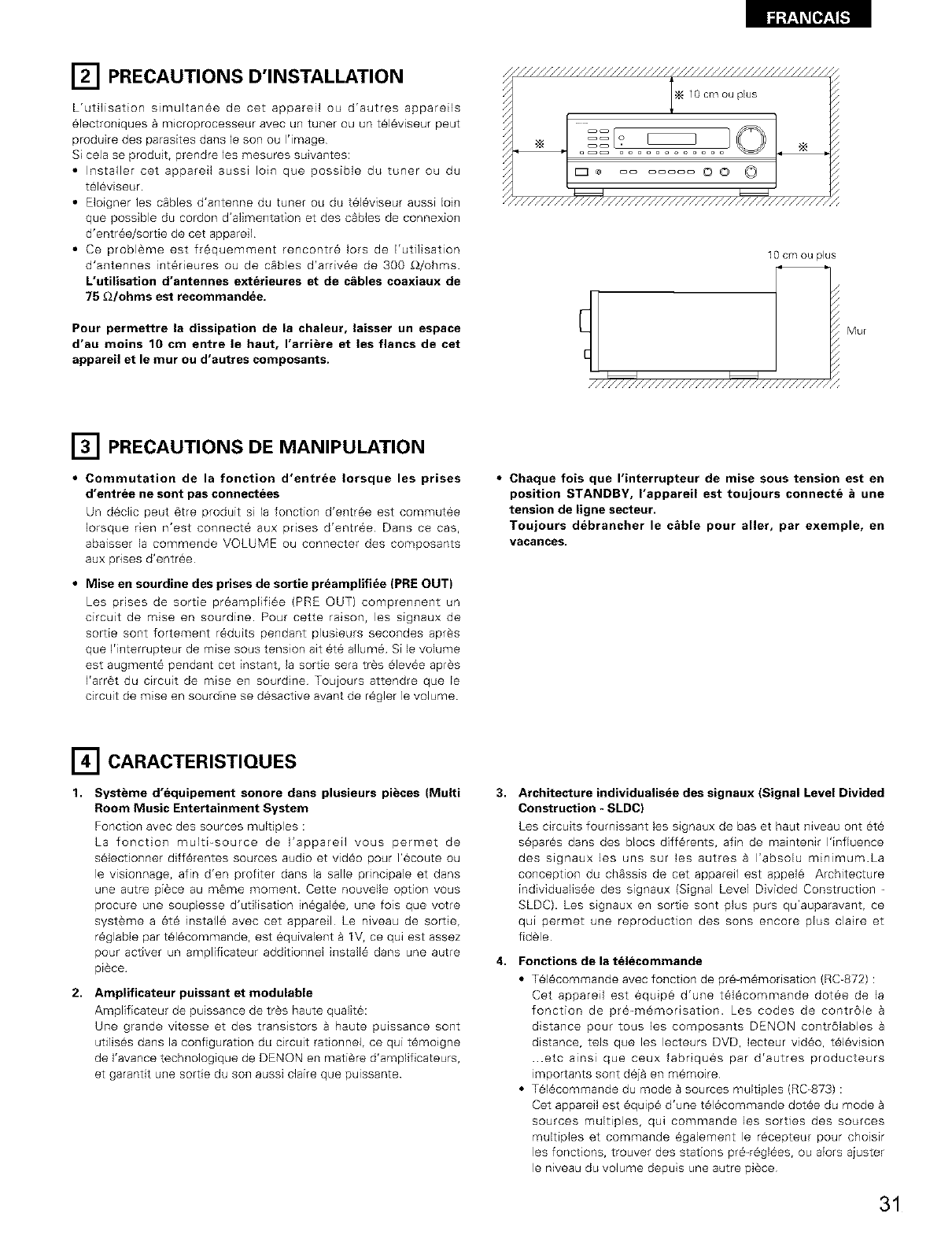
[] PRECAUTIONS D'INSTALLATION
L'utilisation simultan6e de cet appareil ou d'autres appareils
electroniques _ m_croprocesseur avec un tuner ou un t_16viseur peut
produire des parasites dans le son ou I'image
Si cela se produit, prendre les mesures suivantes:
•Installer cet appareil aussi loin que possible du tuner ou du
t_16viseur.
• E]oigner les cables d'antenne du tuner ou du t616viseur aussi loin
que possible du cordon d'alimentation et des c_bles de connexion
d'entr6e/sortie de cet appareil
• Ce probl_me est fr6quemment rencontre lots de I'utilisation
d'antennes int6rieures ou de cSbles d'arriv6e de 300 _/ohms.
L'utilisation d'antennes exterieures et de c_bles coaxiaux de
75 _2/ohms est recommandee.
Pour permettre la dissipation de la chaleur, laisser un espace
d'au moins 10 cm entre le haut, I'arri_re et les flancs de cet
appareil et le mur ou d'autres composants.
///////////////////////////////////////////////,,
N 10 cm ou plus
* ....... OO (3 I
"//////////////////////////////////////////////,
10 cm ou plus
////////////////////////////////////
Mu[
[] PRECAUTIONS DE MANIPULATION
•Commutation de la fonction d'entr_e Iorsque les prises
d'entr_e ne sont pas connectees
Un d_clic peut 6tre produit si la fonction d'entr6e est commutee
Iorsque den n'est connect6 aux prises d'entr6e Dans ce cas,
abaisser la commende VOLUME ou connecter des composants
aux prises d'entr_e
•Mise en sourdine des prises de sortie pr_amplifiee (PRE OUT)
Les prises de sortie preamplifiee (PRE OUT) comprennent un
circuit de raise en sourdine. Pour cette raison, les signaux de
sortie sont fortement r6duits pendant plusieurs secondes apr_s
que I'interrupteur de m_se sous tension air 6t6 allure6 Si le volume
est augment6 pendant cet instant, la sortie sera tr_s _lev6e apr_s
I'arr6t du circuit de raise en sourdine Toujours attendre que le
circuit de mise en sourdine se desactive avant de r6gler le volume
•Chaque fois que I'interrupteur de mise sous tension est en
position STANDBY, I'appareil est toujours connecte _une
tension de ligne secteur.
Toujours debrancher le c&ble pour aller, par exemple, en
vacances.
r-_ CARACTERISTIQUES
1. Systbme d'equipement sonore dans plusieurs pibces (Multi
Room Music Entertainment System
Fonction avec des sources multiples :
La fonction muIti_source de I'appareil vous permet de
selectionner diff6rentes sources audio et vid6o pour ]'ecoute ou
le visionnage, afin d'en profiter dans la salle principale et dans
une autre pi#ce au m6me moment. Cette nouvelle option vous
procure une souplesse d'utilisation in6galCe, une fois que votre
syst_me a et_ installe avec cet appareil Le niveau de sortie,
r_glable par t_l_commande, est equivalent _ IV, ce qui est assez
pour activer un amplificateur additionnel install_ dans une autre
piece
2. Amplificateur puissant et modulable
Amplificateur de puissance de tr_s haute qualite:
Une grande vitesse et des transistors a haute pu=ssance sont
utilis_s dans la configuration du circuit rationnel, ce qui t_moigne
de I'avance technologique de DENON en mati_re d'amplificateurs,
et garantit une sortie du son aussi claire que pu=ssante
3,
4,
Architecture individualisee des signaux (Signal Level Divided
Construction - SLDC}
Les circuits fournissant les signaux de bas et haut niveau ont et_
separ_s dans des blocs diff_rents, afin de maintenir I'influence
des signaux les uns sur les autres a I'absolu minimum.La
conception du chassis de cet appareil est appel¢ Architecture
individualis_e des signaux (Signal Level Divided Construction
SLDC). Les s_gnaux en sortie sont plus puts qu'auparavant, ce
qui permet une reproduction des sons encore plus claire et
fid_le
Fonctions de la t_lecommande
• Tel_commande avec fonction de pr_-m_morisation (RC-872) :
Cet appareil est equip_ d'une t_l_commande dotee de la
fonction de pr_=m_morisation. Les codes de contr61e
distance pour tousles composants DENON contrdlables
distance, tels que les lecteurs DVD, lecteur video, t_l_vision
..etc ainsi que ceux fabdques par d'autres producteurs
=mportants sont d_j_ en memoire
• Tel_commande du mode Bsources multiples (RC=873) :
Cet appareil est _quipe d'une t_lecommande dot_e du mode
sources multiples, qui commande les sorties des sources
multiples et commande _galement le r_cepteur pour choisir
les fonctions, trouver des stations pr_=r_gl_es, ou alors ajuster
le niveau du volume depuis une autre piece
31
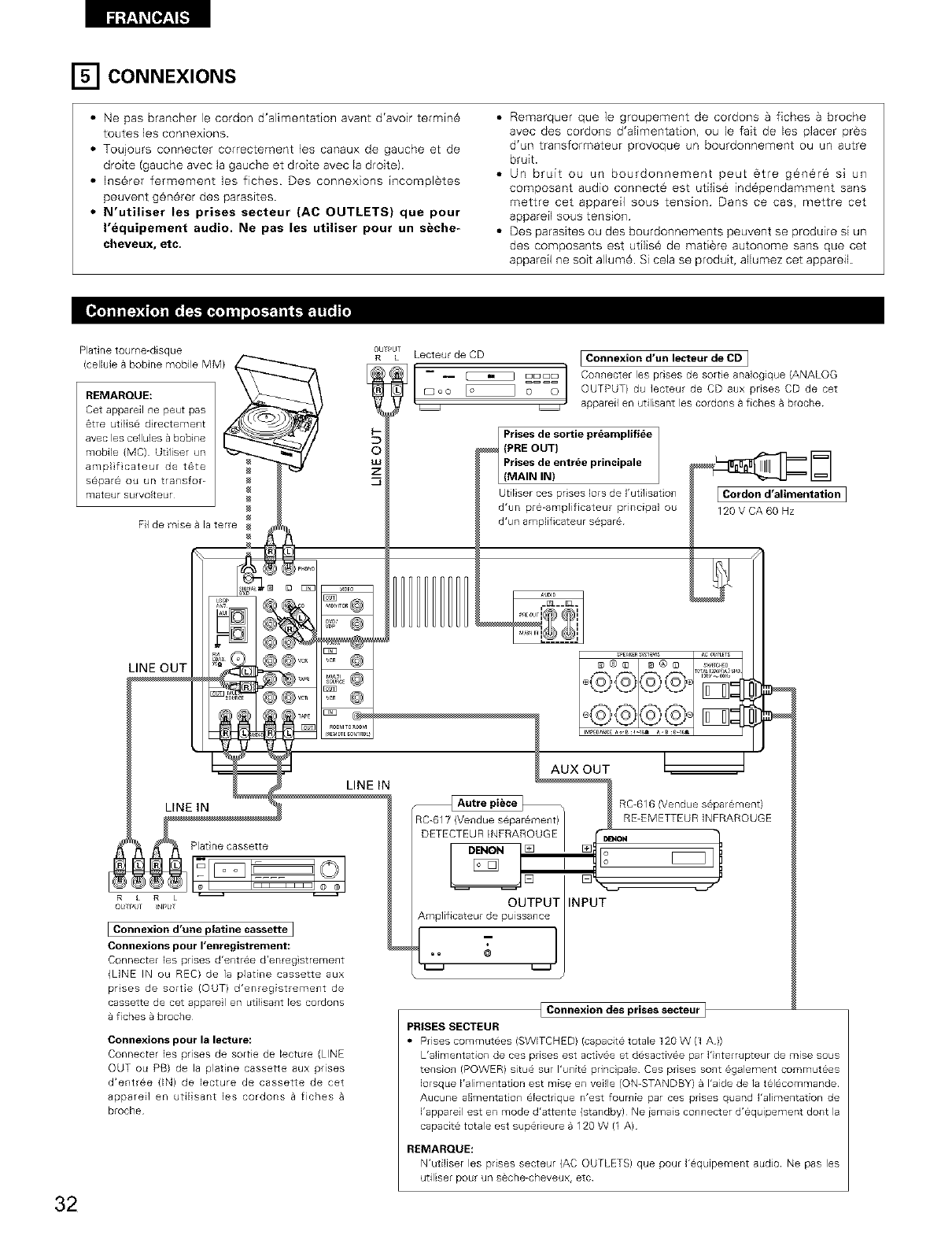
[] CONNEXIONS
• Ne pas brancher le cordon d'alimentation avant d'avoir terrain6
toutes ]es connexions.
• Toujours connecter correctement les canaux de gauche et de
droite (gauche avec la gauche et droite avec la droite).
• Inserer refinement les fiches Des connexions incompl_tes
peuvent gen6rer des parasites.
•N'utiliser les prises seeteur (AC OUTLETS} que pour
I'equipement audio. Ne pas los utiliser pour un seche-
cheveux, etc.
• Remarquer que ]e groupement de cordons a fiches a broche
avec des cordons d'alimentation, ou le fait de los placer pros
d'un transformateur provoque un bourdonnement ou un autre
bruit.
• Un bruit ou un bourdonnement peat _tre g_n6re si un
composant audio connect_ est utiBe ind6pendamment sans
mettre cot appareil seas tension Dans ce cas, mettre cot
apparefl seas tension
• Des parasites ou des bourdonnements peuvent se produire si un
des composants est utflis6 de matiere autonome sans que cot
apparefl ne soit allum6. Si cola se produit, allumez cet appareil
Platine tourne-disque
(celMe a bobine mobile MM)
REMARQUE:
Cot appareil ne peat pas
6tre ut lise d rectement
avec los cellules a bobine
mobile (MC) Utiliser un
ampl ficateur de t6te
separ6 ou un transfor-
mateur survolteur
Fil de raise a la torte
ObT#UT
LLecteur de CD I Connexion d'un lecteur de CD I
-- -- _ E]E]E]C] Connecter los prises de sortie analogique (ANALOG
[:3 oo _ o==0 OUTPUT( da lecteur de CD aax pnses CD de cot
_ appareil en utilisant los cordons a fiches a broche
tPrises de sortie preamplifiee
O(PRE OUT}
Prises de entree principale
(MAIN IN)
Utiliser cos prises ]ors de ]'utilisation
d'un pre-amplificateur principal ou
d'un arnplificateur s@pare
ECordond'alimentation ]
120VCA60 Hz
32
LINE OUT
LINE IN
Plat ne cassette
[Connexion d'une platine cassette ]
Connexions pour I'enregistrement:
LINE IN
Connecter los prises d'entree d'enreg strement
{LINE IN ou REC) de ia platine cassette aux
prises de sortie (OUT) d'enregistrement de
cassette de cot apparel en utilisant los cordons
fiches a broche
Connexions pour la le6ture_
Connecter los prises de sortie de lecture (LINE
OUT ou PB) de la plat ne cassette aux prises
d'entree (IN) de lecture de cassette de cot
appareil en utilisant los cordons a fiches
broche
AUXOUT
RC-617 (Vendue separ6ment)
DETECTEUR INFRAROUGE
DENON
[]
OUTPUT INPUT
Amplificateur de puissance
-1
RC-616 (Vendue s6parement)
RE-EMETTEUR INFRAROUGE
[ Connexion des gi'ises salaMi' }
PRISES SECTEUR
• Prises commutees (SWITCH ED( (capacite totale 120 W (1A ))
L'alimentation de ces prises est activee et desactivee par I'interrupteur de raise sous
tension (POWER) situe sur I'unit@ principale Ces prises sent egalement commutees
Iorsque I'alimentation est raise en veille /ON-STANDBY( a I'aide de la telecommande
Aucune alimentation electrique n'est fournie par ces prises quand Falimentation de
I'appareil est en mode d'attente (standby) Ne iamais connecter d'equipement dent la
capacit@ totale est supedeure a 120 W (1 A)
REMARQUE:
N'utiliser los prises secteur (AC OUTLETS( que pour I'equipement audio Ne pas los
utiliser pour un s6che-cheveux, etc
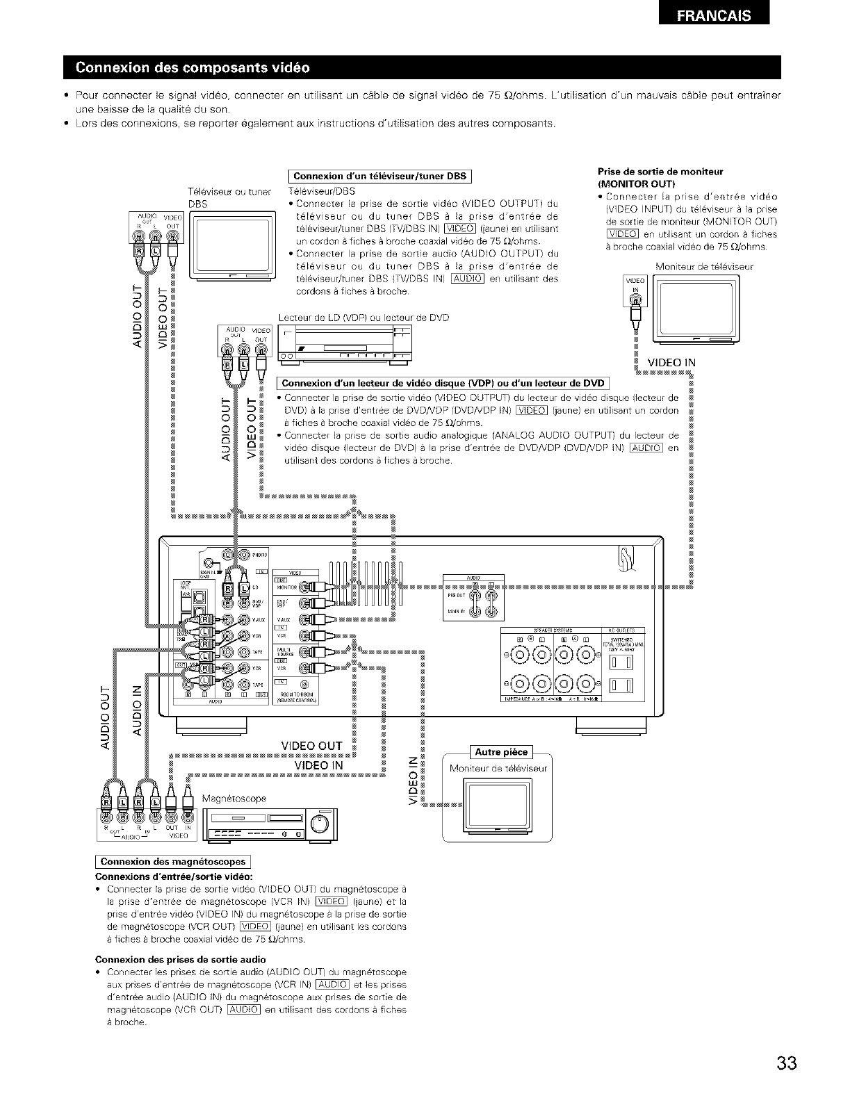
• Pour connecter le signal video, connecter en utilisant un cable de signal vid6o de 75 _2/ohms L'utiJisation d'un mauvais cSble peut entratner
une baisse de la qualit6 du son
• Lors des connexions, se reporter 6galement aux instructions d'utilisation des autres composants
5
©
©
T616viseur ou tuner
DBS
o V,DEa 111
k OUT
I Connexion d'un televiseur/tuner DBS I
T616viseur/DBS
• Connecter la prise de sortie video (VIDEO OUTPUT) du
t@16viseur ou du tuner DBS a la prise d'entree de
televiseudtuner DBS (TV/DBS IN) _ (}aune) en utilisant
un cordon a fiches a broche coaxial video de 75 _dohms
• Connecter la prise de sortie audio (AUDIO OUTPUT) du
t@16viseur ou du tuner DBS a la prise d'entree de
tel6viseur/tuner DBS (TV/DBS IN) _ en utilisant des
cordons a fiches a broche
5
©
©
Prise de sortie de moniteur
(MONITOR OUT)
• Connecter la prise d'entree vid@o
(VIDEO INPUT) du tel6viseur a la prise
de sortie de moniteur (MONITOR OUT)
en utilisant un cordon a fiches
broche coaxial video de 75 _/ohms
Lecteur de LD (VDP) ou lecteur de DVD
...... o_L_! F_
L OU
.... _Z
I Connexion d'un lecteur de video disque (VDP) ou d'un lecteur de DVD I
• Connecter la prise de sortie video (VIDEO OUTPUT) du lecteur de video dsque (lecteur de
DVD) a la prise d'entr@e de DVD/VDP (DVD/VDP IN} _ (}aune) en utilisant un cordon
fiches a broche coaxial video de 75 £!/ohms
• Connecter la prise de sortie audio analogque (ANALOG AUDIO OUTPUT) du lecteur de
video disque {lecteur de DVB la prise d'entree de DVD/VDP {DVD/VDP IN) _ en
ut ]isant des cordons a fiches a broche
Moniteur de televiseur
N --
N
[Connexion des magnetoscopes ]
Connexions d'entree/sortie video:
• COn_lecte_ la prise de sortie vid@o (VIDEO OUT) du magn@toscope
la prse d'entree de magnetoscope (VCR IN) [_ 0aune} et la
prise d'entree video (VIDEO IN) du magnetoscope a la prise de sortie
de magn@toscope (VCR OUT) _ (iaune) en utilisant les cordons
fiches a broche coaxial video de 75 £_Juhms
Connexion des prises de sortie audio
• Connecte_ les prises de sorde audio (AUDIO OUT) du magnetoscope
aux prises d'entree de magnetoscope (VCR IN) _ et les pr4ses
d'entree audio (AUDIO IN) du magnetoscope aux prises de sortie de
magnetoscope (VCR OUT) _ en utilisant des cordons a fiches
broche
33
DIRECTION DE
STATION DE
RADIODIFFUSION
f ANTENNE FM
CABLE
COAXIAL DE
75_ohms
ANTENN E-CADRE AM
(Accessoire)
_@@ .....
_, @@ o .........@
@ @..... _s,_s@
z:_o,,..... @@, ............
@@1@@,,_, _ ®
///_ ////
TERRE
ANTENNE
EXTERIEURE
AM
Antenne interieure FM
(Accessoirel
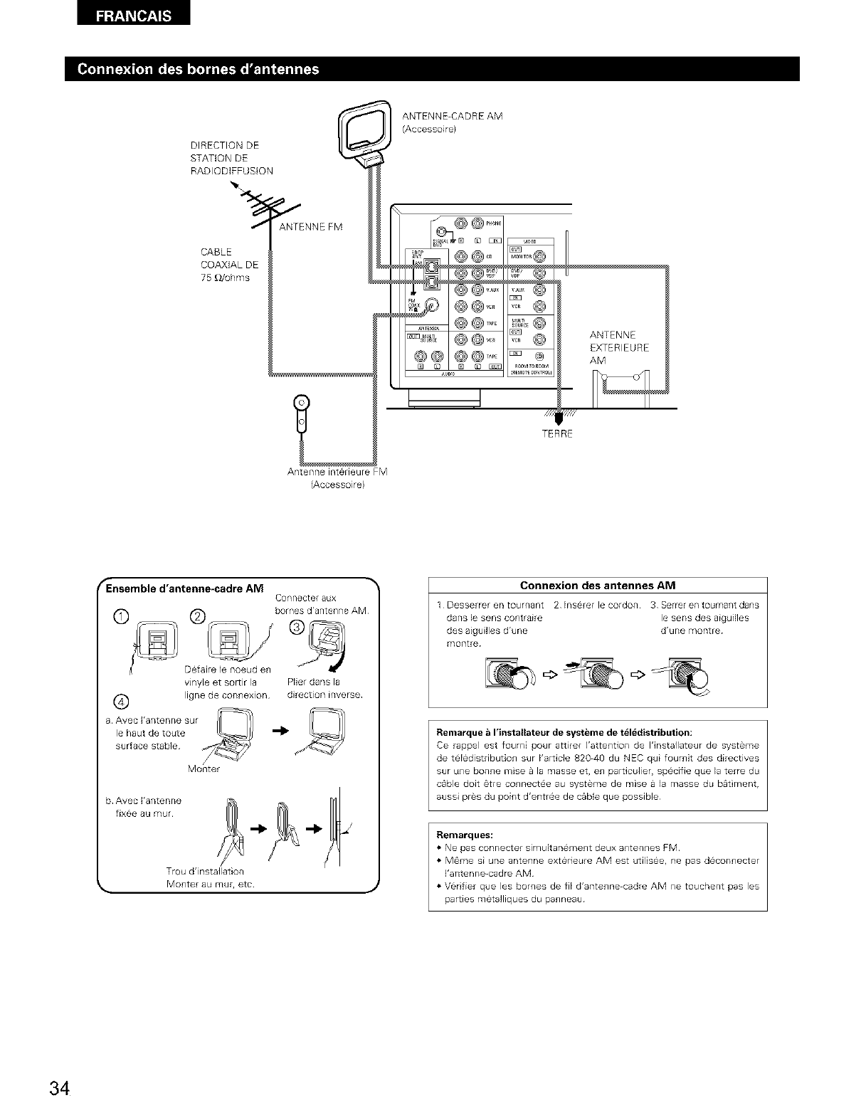
fEnsemble d'antenne-cadre AM
C©nnecte_ aL/X
bo_r_e _ drante_7ne AM
Defaire le noeud en
vinyle et sorur la Plier dans la
i_ ligne de connexion direction inverse
a Avec I'anterlne sur
le haut de toute
surface stable
Monter
Trou d'installation
_, Monter au tour, etc J
Connexion des antennes AM
1 Desserrer @n tournsnt 2 Ins@re_ le co;don 3 Serr@[ en tourns_lt dans
dans le sens contraire le sens des aiguilles
des aiguilles d'une d'une montre
montre
Remarque _ rinstallateur de syst_me de t616distribution:
Ce rappel est fourni pour a_irer Kattention de I'installateur de systerne
de teledistnbution sur Karticle 820-40 du NEC qui foumit des directives
sur une bonne raise a la masse et, en particulier, specifie que la terre du
c_ble doit 6tre connectee au systeme de mise a la masse du bat ment,
aussi prBs du point d'entree de c&ble que possible
Flemai'ques:
• Ne pas connecter simdtanemeRt deux 8RtenRes FM
• M@me si une antenne exterieure AM est utilisee, ne pas deconnecter
I'antenne-cadre AM
• Verifier que les bornes de fil d'antenne-cadre AM ne touchent pas les
pardes metalliques du banneau
34
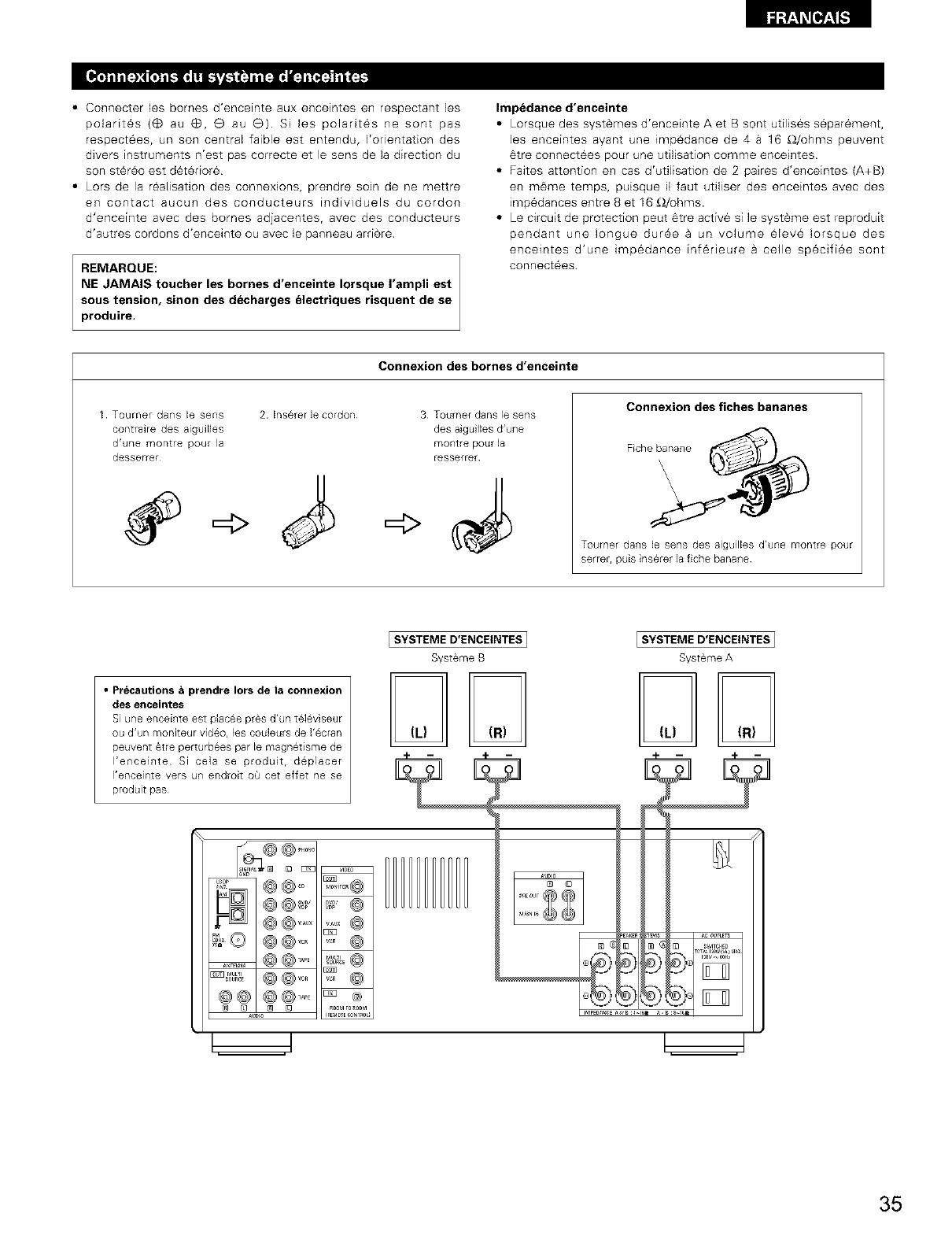
• Connecter les bornes d'enceinte aux enceintes en respectant les
polarit6s (_ au @, e au G). Si les polarit6s ne sont pas
respect6es, un son central faible est entendu, I'orientation des
divers instruments n'est pas correcte et le sens de la direction du
son st6r_o est d6t_rior6
• Lors de la r_alisadon des connexions, prendre soin de ne mettre
en contact aucun des conducteurs individuels du cordon
d'enceinte avec des bomes adjacentes, avec des conducteurs
d'autres cordons d'enceinte ou avec le panneau arri_re
REMARQUE:
NE JAMAIS toucher les bornes d'enceinte Iorsque I'ampli est
sous tension, sinon des decharges electriques risquent de se
produire.
Impedance d'enceinte
• Lorsque des syst_mes d'enceinte A et B sont utilises separ6ment,
les enceintes ayant une impedance de 4 a 16 _I/ohms peuvent
6tre connectees pour une utilisation comme enceintes.
• Faites attention en cas d'utilisation de 2 paires d'enceintes (A+B)
en m6me temps, puisque il faut utiliser des enceintes avec des
imp6dances entre 8 et 16 _2/ohms.
• Le circuit de protection peut 6tre active si le syst_me est reproduit
pendant une Iongue dur6e a un volume _lev6 Iorsque des
encemtes d'une imp6dance inf6rieure a ceile specifi6e sont
connect6es
Connexion des bornes d'enceinte
1 Tourner daRs I@ s@ns
contraire des aiguilles
d'unemontre pour la
desserrer
2 Insererle cordon 3 TotJ[rl@r daRS le seas
des aiguillesd'une
Fnont[e pou[ 18
resserre_
Connexion des fiches bananes
Toumer dans le sens des aiguilles d'une montre pour
serrer, puis inserer lafiche banane
• Precautions aprendre Iors de la connexion
des enceintes
Si une enceinte est placee pres d'un televiseur
ou d'un rnoniteur video, les couleurs de I'ecran
peuvent _tre perturbees par le magnetisme de
I'enceinte Si ce]a se produt, deplacer
I'enceinte vers un endroit oQ cet effet ne se
produit pas
[SYSTEME D'ENCEINTES ]
Systeme B
[SYSTEME D'ENCEINTES1
Systeme A
m m
35
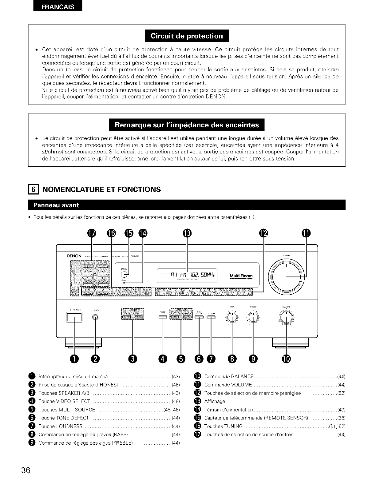
,, Cet appareil est dote d'un circuit de protection _ haute vitesse. Ce circuit protege les circuits internes de tout
endommagement eventuel dO a I'afflux de courants importants Iorsque les prises d'enceinte ne sont pas completement
connectees ou Iorsqu'une sortie est g6ner6e par un court-circuit.
Darts un tel cas, le circuit de protection fonctionne pour couper la sortie aux enceintes. Si cela se produit, eteindre
I'appareil et verifier les connexions d'enceinte. Ensuite, mettre a nouveau I'appareil sous tension. Apres un silence de
quelques secondes, le recepteur devrait fonctionner normalement.
Si le circuit de protection est a nouveau active bien qu'[I n'y ait pas de probleme de c_blage ou de ventilation autour de
I'appareil, couper I'alimentation, et contacter un centre d'entretien DENON.
• Le circuit de protection peut 6tre active sl I'appareil est utilise pendant une Iongue duree _ un volume 61eve Iorsque des
enceintes d'une impedance inf6rleure a celle specifiee (par exemple, enceintes ayant une impedance inferieure _ 4
_2/ohms) sont connectees. SI le circuit de protection est active, la sortie des enceintes est coupee. Couper I'alimentation
de I'appareil, attendre qu'il refroidisse, ameliorer la ventilation autour de lui, puis remettre sous tension.
[] NOMENCLATURE ET FONCTIONS
• Pour les details sur les fonctions de ces pi6ces, se reporter aux pages donn6es entre parentheses ( )
T
.................£ IFt_ I[_2._ONHz Multi Room
.........................,._._._ _._ _.¢.9._.._@._.@. _o._._ 0
)0 ,)
_]_ Interrupteur de mise en marche .................................... (43)
Prise de casque d'_coute (PHONES) .............................. (48)
Touches SPEAKER A!B ................................................ (43)
Touche VIDEO SELECT ................................................ (48)
Touches MULTI SOURCE ....................................... (45, 46)
Touche TONE DEFECT ................................................ (44)
Touche LOUDNESS ...................................................... (44)
Commande de r_glage de graves (BASS) ........................ (44)
_) Commande de r6glage des aigus (TREBLE) .................. (44)
_) Commande BALANCE ................................................... (44)
_) Commande VOLUME ................................................... (44)
(_ Touches de selection de m_moire pr_r@glee ............... (B2)
_) Atfichage
(_ T_moin d'alimentation ................................................... (43)
Capteur de tel@commande (REMOTE SENSOR) ............... (38)
_) TouchesTUNING ................................................... (B1, 52)
_]_ Touches de selection de source d'entr6e ........................ (44)
36
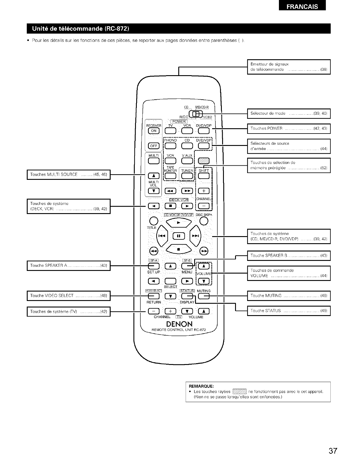
Fa'J:!'_[I,]_[,..']
• Pour les details sur les fonctions de ces pi6ces, se reporter aux pages donn6es entre parentheses ( )
I Touches MULTi SOURCE ......... {45, 46) t
/_chK:vdct#Yt'?:t..................,3_,42,t
ITouche SPEAKER A ........................ (43) I
ITouche VIDEO SELECT .................. (48) I
ITouches de systeme (TV) ............... (42)
I
CD MD/CD-
TV VCR DVD VDP |I
PHONO CD DVD/VDP_ I
MULTI VCR VAUX I
I::Z} I:Z_ (:Z)i I:Z3
_40N TOR TUNER I
C_ ...._... ,
MULTI "
VOL
-- CHANN£[
, i
SETUR MENU JVOLUMEI
, i
I I
C_ CD C_ L...._..J
SELECT _ MUTING
L_T DENON
E CONTROLUNIT R_C-872 _,
I SElecteurde mode .................. (39, 40) I
t Touches POWER ..................... (42, 43) I
S'_;etCteeeJt? !1 ?°utt: ....................... (44)
:%1:1:0:1';,:':°?d:..................,E2/
t/_:V;,_t_:%%P/........./38,42/
_1 ToucheSPEAKERB........................143/I
t ToLCh MSEd: c° m rr:a n !: .................... {44)
I Touche MUTING ........................... {48) I
Lt Touche STATUS ........................... {49} I
REMARQUE:
• Les touches rayees _ ne fonctionnent pas avec le cet appareil
(Rien ne se passe Iorsqu'elles sont enfonc6es )
37
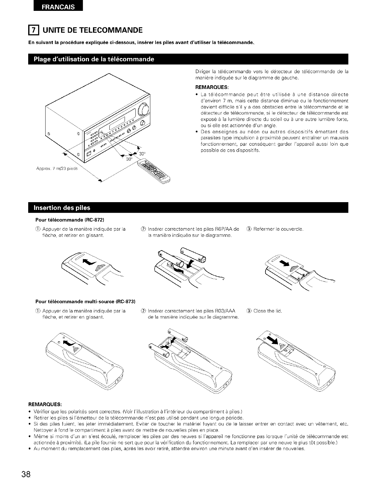
[] UNITE DE TELECOMMANDE
En suivant la procedure expliquee ci-dessous, inserer les piles avant d'utiliser la t_lecommande,
Diriger la t616commande vers le detecteur de t616commande de la
mani#re indiqu6e sur le diagramme de gauche.
REMARQUES:
• La t616commande peut _tre utilisee & une distance dbecte
d'environ 7 m, mais cette distance diminue ou le fonctionnement
devient difficile sql y a des obstacles entre la t6]_commande et le
detecteur de t61_commande, si le detecteur de t61_commande est
expos_ & ]a lumi_re directe du soleil ou a une autre lumi_re forte,
ou s[ e]le est actionn6e d'un angle
• Des enseignes au neon ou autres dispositifs emettant des
parasites type impulsion a proximit6 peuvent entrafner un mauva_s
fonctionnement, par cons6quent garder I'appareil aussi loin que
possible de ces dispositifs.
Approx 7 m/23 p[eds _
Pour t_lecommande (R0-872)
lj Appuyer de la man,ere _nd_quee par la
fl#che, et retirer en glissant.
,:.2_InsUrer correctement les piles R6P/AA de (3) Refermer le couvercle
la mani_re indiqu6e sur le diagramme
Pour t_lecommande multi-source (RC-873)
lj Appuyer de la manlere _ndlquee par la ,_2_Ins_rer correctement les piles R03/AAA (3) Close the lid.
fl#che, et retirer en glissant, de la mani_re indiquee sur le diagramme
REMARQUES:
•V_rifier que les polarites sont correctes. (Voir I'illustration _ I'intSrieur du compartiment a piles)
• Retirer les piles si I'_metteur de la t_lecommande n'est pas utilis_ pendant une Iongue p_riode
• Si des piles fuient, les jeter imm_diatement. Eviter de toucher le mat_del fuyant ou de le laisser entrer en contact avec un v_tement, etc.
Nettoyer _ fond le compartiment a piles avant de mettre de nouvelles piles en place
• MSme si moins d'un an s'est 8coule, remplacer les piles par des neuves si I'appareil ne fonctionne pas Iorsque I'unit_ de t_l_commande est
actionn_e 8 proximitY. (La pile fournie ne sert que pour la v_rification du fonctionnement. La remplacer par une neuve le plus t6t possible.)
• Au moment du remplacement des piles, apr#s les avoir retire, attendre environ une minute avant d'en insurer de nouvelles
38
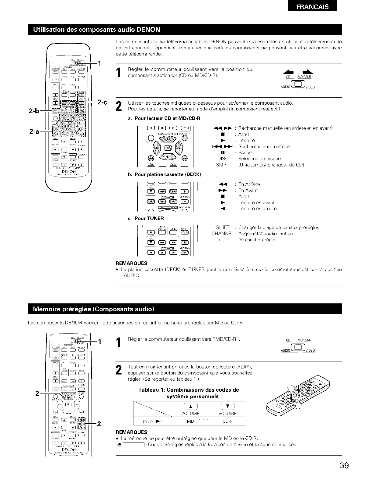
2-5--
--1
-2-C
Les composants audio t616commandables DENON peuvent 6tre contr616s en util[sant la t616commande
de cet appareil. Cependant, remarquer que certains composants ne peuvent pas 6tre actionn6s avec
cette t_16commande
R6gler le commutateur coulissant vers la position du
composant a actionner (CD ou MD/CD_R). CD MD/CD-R
Utiliser les touches indiqu_es cFdessous pour actionner le composant audio.
Pour les d6tails, se reporter au mode d'emploi du composant respectif.
a. Pour lecteur CD et MD/CD-R
44,_1_ : Recherche manuelle (en arri@re et en avant)
• : Arr6t
: Lecture
1_141,1=,_-I: Recherche automatique
II : Pause
DISC : S61ection de disque
SKIP+ (Uniquement changeur de CD)
b. Pour platine cassette (DECK)
DBC $KI#4
44 : En ArtiSte
_l,_ : En Avant
• : Arr6t
I_ : Lecture en avant
_1 : Lecture en arri_re
c, Pour TUNER
SHIFT : Changer la plage de canaux prer6gl6s
CHANNEL : Augmentation/diminution
+ , -de canal pr6r_gl6
REMARQUES:
• La platine cassette (DECK) et TUNER peut 6tre util[s6e Iorsque le commutateur est sur la position
"AUDIO"
Les composants DENQN peuvent 6tre actionn6s en reglant la m6moire pr6-r6gl6e sur MD ou CD-R.
m
DENON
--1
-2
Regler le commutateur coulissant vers "MD/CD=R". CD MD/CD-R
Tout en maintenant enfonce le bouton de lecture (PLAY),
appuyer sur le bouton du composant que vous souhaitez
r_gler (Se reporter au tableau 1.)
Tableau 1: Combinaisons des codes de
systeme personnels
VOLUME VOLUME
PLAY (1_) MD CD_R
REMARQUES:
• La m_moire ne peut @trepr@r_gl@eque pour le MD ou le CD-R.
_ Codes pr@r@glesregl@sa la livraison de I'usine et Iorsque r@initialis@s
39
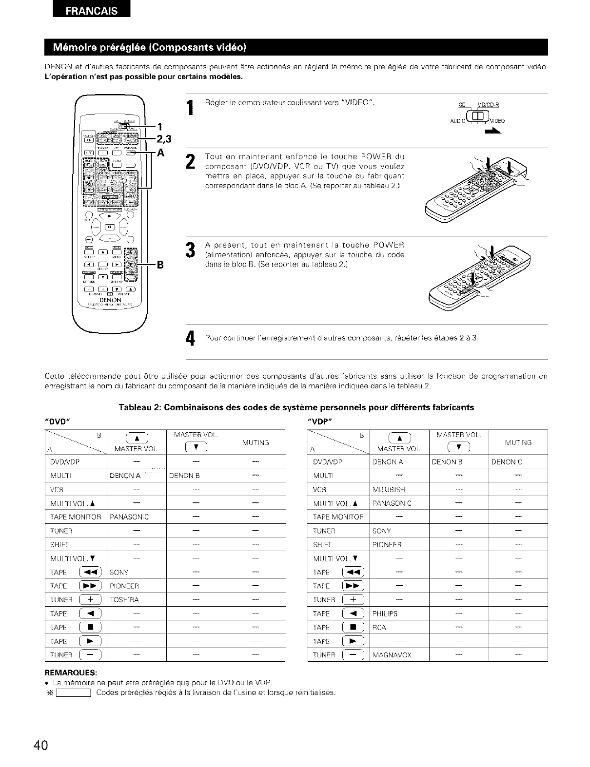
DENON et d'autres fabricants de composants peuvent 6tre actionn6s en r6glant la memoire pr_r6gl6e de votre fabdcant de composant vid6o.
L'op_ration n'est pas possible pour certains modeles.
--I
-2,3
-A
Regler le commutateur coulissant vers "VIDEO" CD MD/CD-R
2Tout en maintenant enfonc6 le touche POWER du
composant (DVD/VDP. VCR ou TV) que vous voulez
mettre en place, appuyer sur la touche du fabriquant
correspondant dans le bloc A. (Se reporter au tableau 2)
A present, tout en maintenant la touche POWER
(a]imentation) enfonc_e, appuyer sur la touche du code
darts le bloc B. (Se reporter au tableau 2}
Pour continuer I'enregistrement d'autres composants, r6p6ter les 6tapes 2 a 3
Cette t616commande peut 6tre utilisee pour actionner des composants d'autres fabncants sans utiliser la fonction de programmation en
enregistrant le nom du fabdcant du composant de la mani_re indiqu6e de la mani_re indiquee dans le tableau 2.
Tableau 2: Combinaisons des codes de systeme personnels pour differents fabricants
"DVD"
A _
DVD/VDP
MULTi
VCR
MULTi VOL •
TAPEMONITOR
TUNER
SHIFT
MULTi VOL •
TAPE
TAPE
TUNER _-_
TAPE
TAPE
TAPE @
TUNER _
REMARQUES:
MASTER VOL
MUTING
MASTERVOL [_ }
DENON A DENON B --
PANASONIC -- --
SONY -- --
PIONEER -- --
TOSHIBA -- --
"VDP"
DVD/VDP
MULTI
VCR
MULTI VOL •
TAPE MONITOR
TUNER
SHIFT
MULTI VOL •
TAPE
TAPE
TUNER [_ }
TAPE
TAPE
TAPE
TUNER _
MASTER VOL
MUTING
MASTER VOL (_
DENON A DENON B DENON C
MITUBISHI -- --
PANASONIC -- --
SONY -- --
PIONEER -- --
PHILIPS -- --
RCA -- --
MAGNAVOX -- --
• La memoire ne peut @tre pr6r@gl6e que pour le DVD ou le VDP.
_ Codes prer6gles r@gl6s a la livraison de I'usine et Iorsque r6initialis6s.
40
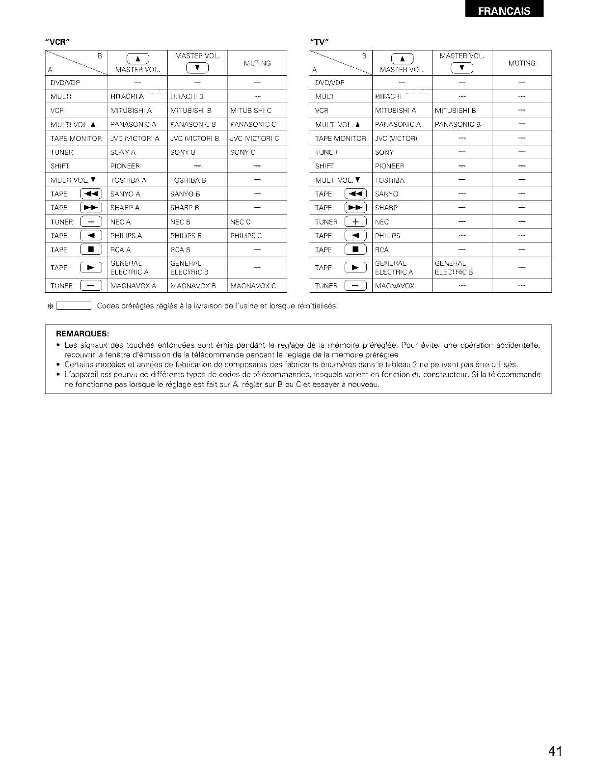
Fa'_'_ [I,]_.[,..']
"VCR"
B
A _
DVD/VDP
MULTi
VCR
MULTi VOL •
TAPE MONITOR
TUNER
SHIFT
MULTi VOL •
TAPE
TAPE
TUNER _-_
TAPE [[_
TAPE
TAPE
TUNER (_
MASTER VOL MUTING
MASTER VOL
HITACHI A HITACHI B
MITUBISHI A MITUBISHI B MITUBISHI C
PANASONIC A PANASONIC B PANASONIC C
JVC (VICTOR) A JVC (VICTOR) B JVC (VICTOR) C
SONY A SONY B SONY C
PIONEER -- --
TOSHIBA A TOSHIBA B
SANYO A SANYO B --
SHARP A SHARP B --
NEC A NEC B NEC C
PHILIPS A PHILIPS B PHLIPS C
RCA A RCA B --
GENERAL GENERAL
ELECTRIC A ELECTRIC B
MAGNAVOX A MAGNAVOX B MAGNAVOX C
"TV"
DVDpdDP
MULTI
VCR
MULTI VOL •
TAPE MONITOR
TUNER
SHIFT
MULTI VOL •
TAPE
TAPE
TUNER _-_
TAPE [[_
TAPE
TAPE
TUNER (_
MASTER VOL MUTING
MASTER VOL
HITACHI -- --
MITUBISHI A MITUBISHI B
PANASONIC A PANASONIC B
JVC (VICTOR) -- --
SONY -- --
PIONEER -- --
TOSHIBA -- --
SANYO -- --
SHARP -- --
NEC -- --
PHILIPS -- --
RCA -- --
GENERAL GENERAL __
ELECTRIC A ELECTRIC B
MAGNAVOX -- --
_ Codes prer6gles r0gl6s Bla livraison de I'usine et Iorsque r6initialis6s.
REMARQUES:
• Les signaux des touches enfonc6es sont emis pendant le rOglage de la mOmoire pr6rOgl6e Pour Oviter une op6ration accidentelle,
recouvrir la fen@tre d'6mission de la t616commande pendant le rOglage de la memoire pr6r6glOe
• Certains mod@les et annOes de fabrication de composants des fabricants enum6r6s dans le tableau 2 ne peuvent pas @treutilises.
• L'appareil est pourvu de diffOrents types de codes de t6lOcommandes, lesquels varient en fonction du constructeur. Si la tOl6commande
ne fonctionne pas Iorsque le r6glage est fait sur A, r6gler sur B ou C et essayer Bnouveau
41
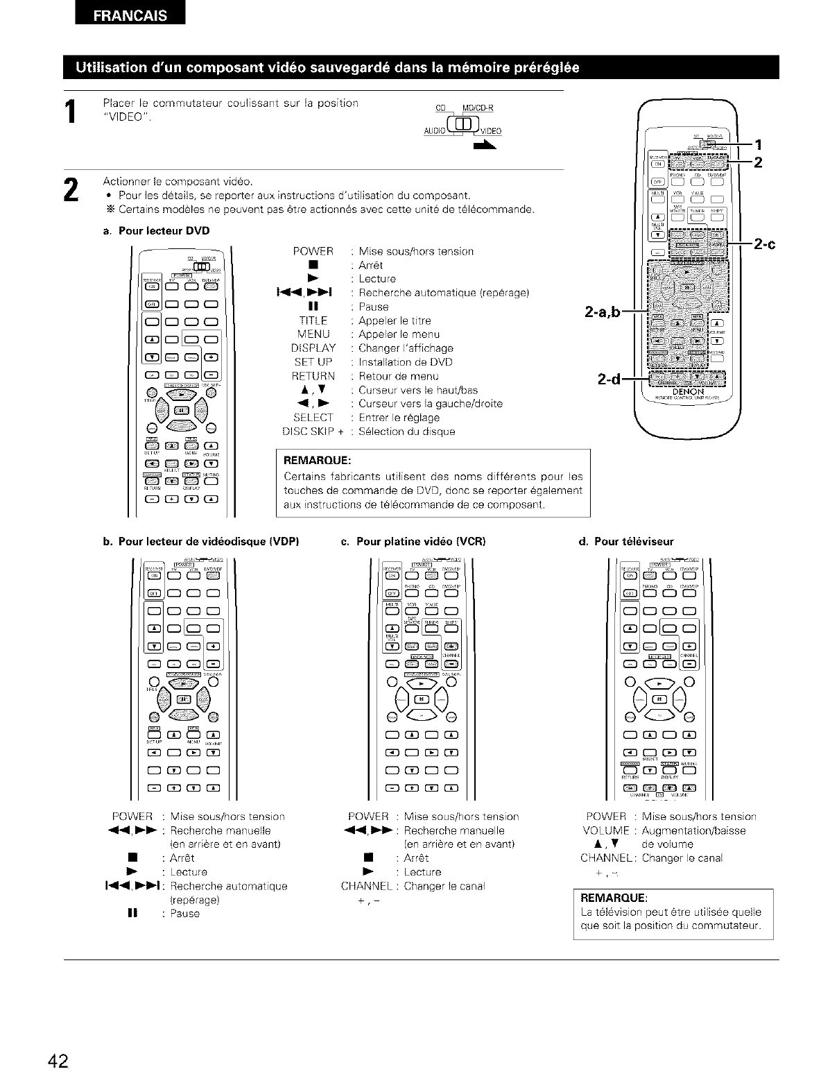
IPlacer le commutateur coufissant sur la position
"VIDEO". CD MD/CD-R
AUOIOI_ VIDEO
Actionner le composant video
• Pour les d_tails, se reporter aux instructions d'udfisation du composant.
•_ Certains modeles ne peuvent pas 6tre actionn6s avec cette unit_ de t616commande
a. Pour lecteur DVD
POWER : Mise sous/hors tension
•: Arr6t
I_ : Lecture
1_1_1,_ : Recherche automatique (rep_rage)
n:Pause
TITLE : Appeler le titre
MENU : Appeler le menu
DISPLAY : Changer I'affichage
SET UP : Installation de DVD
RETURN : Retour de menu
•, • : Curseur vers le haut/bas
_1, I_ : Curseur vers la gauche/droite
SELECT : Entrer le r6giage
DISC SKIP + : S61ection du disque
REMARQUE:
Certains fabricants udlisent des noms diff6rents pour les
touches de commande de DVD, doric se reporter egalement
aux instructions de t_l_commande de ce composant
--1
--2
-2-C
b. Pour lecteur de videodisque (VDP) c. Pour platine video (VCR) d. Pour televiseur
°o o0
@"0"%
POWER : Mise sous/hors tension POWER : Mise sous/hors tension
_1_1,1_1_ : Recherche manuelle _1_1,1_1 '_: Recherche manuelle
(en arriere et en avant) (en arr@re et en avant)
• : Arr_t • : Arr_t
I_ : Lecture I_ : Lecture
I_l_l,ll_Jl_l : Recherche automatique CHANNEL : Changer le canal
(rep_rage) +, -
II : Pause
O^Q^O
POWER : Mise sous/hors tension
VOLUME : Augmentation/baisse
•, • de volume
CHANNEL: Changer le canal
+ ,-
REMARQUE:
La television peut _tre utilis_e quelle
que soit la position du commutateur.
42
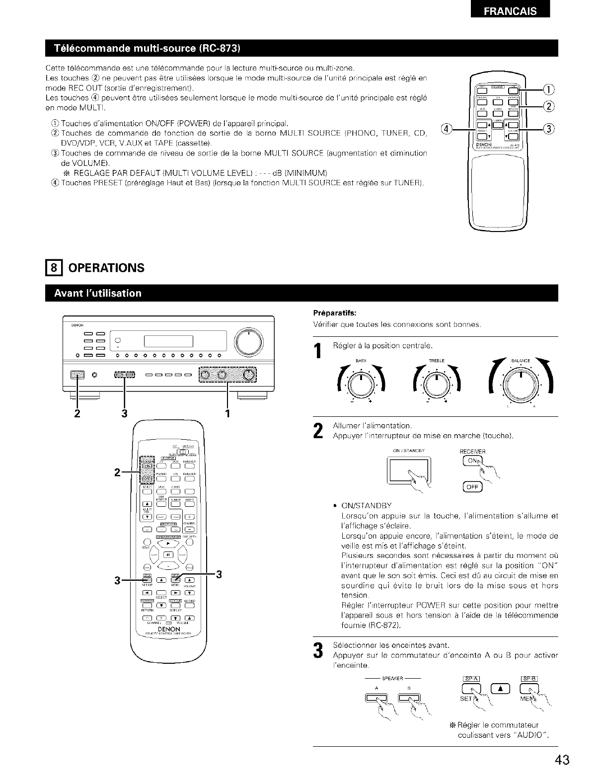
Cette t_16commande est une t61_commande pour ]a lecture multFsource ou multi zone.
Les touches {2_ne peuvent pas 6tre utilis6es Iorsque le mode multFsource de I'unit6 pdncipale est r6gl6 en
mode REC OUT (sortie d'enregistrement)
Les touches (4_peuvent 6tre utilis6es seulement Iorsque le mode multFsource de I'unite principale est r_gl6
en mode MULTI.
O_Touches d'alimentation ON/OFF (POWER) de I'appareil principal.
(2)Touches de commande de fonction de sortie de la borne MULTI SOURCE (PHONO, TUNER, CD,
DVD/VDP, VCR, V.AUX et TAPE (cassette)
(3)Touches de commande de niveau de sortie de la borne MULTI SOURCE (augmentation et diminution
de VOLUME).
REGLAGE PAR DEFAUT (MULTI VOLUME LEVEL) : - - -dB (MINIMUM)
(4_Touches PRESET (pr6r_glage Haut et Bas) (lorsque la fonction MULTI SOURCE est regl6e sur TUNER).
rh©
v
[] OPERATIONS
_ O
o _ o o o o o o o o o o
2 3 1
Preparatifs:
V6r[fier que toutes les connexions sont bonnes
1R_gler a la position centrale.
TREBLE
Allumer I'alimentation.
Appuyer I'interrupteur de raise en marche (touche).
ON /STANDBY RECEIVER
ON/STANDBY
Lorsqu'on appuie sur la touche, I'alimentation s'allume et
I'affichage s'eclaire
Lorsqu'on appuie encore, I'alimentation s'eteint, le mode de
veille est mis et I'affichage s'@teint.
Plusieurs secondes sont n@cessaires _ partir du moment oO
I'interrupteur d'alimentation est r@gl_ sur la position "ON"
avant que le son soit _mis. Ceci est dO au circuit de mise en
sourdine qui evite le bruit Iors de la mise sous et hors
tension
R@gler I'interrupteur POWER sur cette position pour mettre
I'appareil sous et hors tension a I'aide de la t@lecommende
foumie (RC-872)
S@lectionner les enceintes avant.
Appuyer sur le commutateur d'enceinte A ou B pour activer
I'enceinte
ME_ _
,_ R_gler le commutateur
coulissant vers "AUDIO".
43

i_1:_.__[_]_. -]
1 3
r%/ i I
L_.f_...........
{_o O0 0
--1
-3
Appuyer sur la touche de la source de programme Breproduire
EX 1: CD co cu
2
3
EX 2: TAPE TAPE TAPE
MONI,OR MO_qlTOR
• Appuyer une nouvele lois sur la touche pour changer la source
I'entr6e TAPE MONITOR, 8 nouveau pour annulet I'entree
Commencer la lecture sur le composant s61ectionn6.
Pour les instructions d'ut/isation, se reporter aux manuels des
divers composants
Ajuster la commande VOLUME.
VOLU_ E V_
_ 0
0 _ 0 0 00 000000
34 2 1
1
2
3
Regler la commande BALANCE (6qulibre)
avant gauche/droite. BJ,L*,C=
Tour net la commande dansle sens _. "O. _
inverse des aiguilles d'une montre pour
r_duire le volume du canal droit, dans le
sens des aiguilles d'une montre pour
augmenter le volume du canal gauche
Ajuster le commande BASS (graves) et le TREBLE (aigu6s).
BASS
©Tourner la commande dans le sens des
aiguiles d'une montre pour augmenter
les graves, dans le sens inverse des
aiguilles d'une montre pour les r@duire
Tourner la commande dans le sens des
aiguilles d'une montre pour augmenter
les aigu_s, darts le sens inverse des
aiguilles d'une montre pour les r@duire
Appuyer sur la touche TONE DEFEAT
(d@sactivation).
Utiliser cette touche Iorsque vous ne
voulez pas regler le son.
TONE
OEFEAT
4Appuyer sur la touche LOUDNESS
(compensation physiologique).
Appuyer sur le touche de compensation
physiologique lots de I'_coute de la
musique a un niveau de volume bas Les
notes basses et aigu_s sont corrigees
afin de produire un son naturel
Le touche LOUDNESS (compensation physiologique) peut
@tre utlis@ quand le mode TONE DEFEAT ON
44
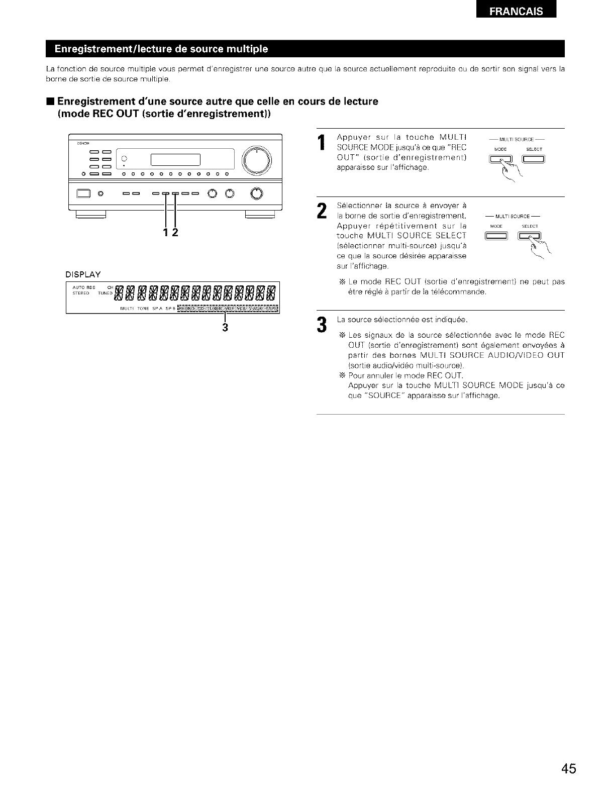
F_ [l_,[.']
La fonction de source multiple vous permet d'enregistrer une source autre que la source actuellement reproduite ou de sortir son signal vers la
borne de sortie de source multiple
•Enregistrement d'une source autre que celle en cours de lecture
(mode REC OUT (sortie d'enregistrement))
D_ON
o _ o o o o ooo o o o
Do == [_] OO
12
DISPLAY
MU_T TONE SPA SP_
a
1Appuyer sur la touche MULTI
SOURCE MODE jusqu'_ ce que "REC
OUT" (sortie d'enregistrement)
apparaisse sur I'affichage
MULT_SOURCE
_ODE SELECT
2S_lectionner la source _ envoyer
la borne de sortie d'enregistrement. MULTISOURCE
Appuyer rep6titivement sur la MODE EECT
touche MULTI SOURCE SELECT _ _[_
(selectionner multi-source) jusqu'a
ce que la source d6sir6e apparaisse --.
sur l'afflchage
Le mode REC OUT (sortie d'enregistrement) ne peut pas
6tre r6g16 a partir de la t616commande.
3La source s61ectionn_e est indiqu6e
•_ Les signaux de la source s61ectionn6e avec le mode REC
OUT (sortie d'enregistrement) sont egalement envoy6es
partir des bornes MULTI SOURCE AUDIO/VDEO OUT
(sortie audio/vid6o multi_source)
Pour annulet le mode REC OUT.
Appuyer sur la touche MULTI SOURCE MODE jusqu'a ce
que "SOURCE" apparaisse sur Yaffichage.
45
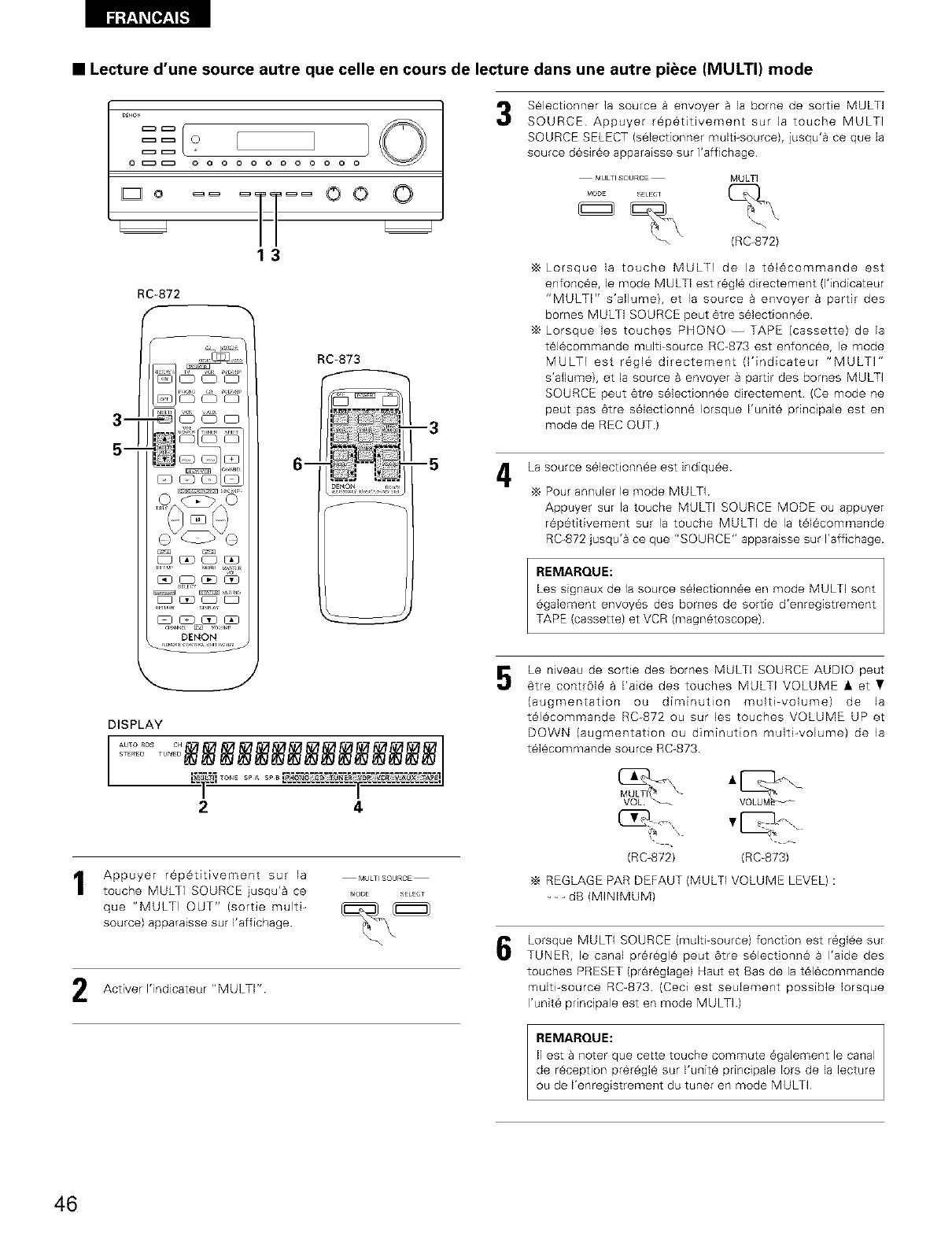
•Lecture d'une source autre que celle en cours de lecture dans une autre piece (MULTI) mode
c=_ c=_ 0
oC_ oo o o o o o o o o
3
_
5--
S_lectionner ]a source a envoyer & la borne de sortie MULTI
SOURCE Appuyer r_p6titivement sur la touche MULTI
SOURCE SELECT (selectionner multi-source), jusqu'a ce que la
source d6sir6e apparaisse sur ]'affichage
MULTI SOURCE MULTI
(RC-872)
13
RC-872
_J_
RC-873
_
--3
--5
DE_Ot4 .,.,,,
L
DENON
DISPLAY
STEREO....... TUN EC_ _ _ ___
2 4
Appuyer r_p@titivement sur la MULTSOURCE
touche MULTI SOURCE jusqu'a ce _ooE SELEOT
que "MULTI OUT" (sortie multi-
source) apparaisse sur I'affichage
Activer I'indicateur "MULTI"
,_ Lorsque la touche MULTI de la t_l_commande est
enfonc_e, le mode MULTI est r_gl_ directement (Kindicateur
"MULTI" s'allume), et la source a envoyer a partir des
bomes MULTI SOURCE peut _tre s_lectionn_e
Lorsque les touches PHONO -- TAPE (cassette) de la
t_lecommande multi-source RC-873 est enfonc_e, le mode
MULTI est r_gl_ directement (l'indicateur "MULTI"
s'aflume), et la source & envoyer a partir des bornes MULTi
SOURCE peut _tre selectionn_e directement (Ce mode ne
peut pas _tre selectionn_ Iorsque I'unite pdncipale est en
mode de REC OUT)
La source s_lectionn_e est indiqu_e
Pour annulet le mode MULTI.
Appuyer sur la touche MULTI SOURCE MODE ou appuyer
rep_titivement sur la touche MULTI de la t#lecommande
RC-872 jusqu'a ce que "SOURCE" apparaisse sur I'affichage.
REMARQUE:
Les signaux de Is source s_lectionn_e en mode MULTI sont
egalement envoy_s des bornes de sortie d'enregistrement
TAPE (cassette) et VCR (magnetoscope)
Le niveau de sortie des bornes MULTI SOURCE AUDIO peut
_tre contr6[_ a I'aide des touches MULTI VOLUME • et •
(augmentation ou diminution multi-volume) de la
t_l_commande RC872 ou sur les touches VOLUME UP et
DOWN (augmentation ou diminution multi-volume) de la
t_lecommande source RC-873.
(RC-872) (RC-873)
•_ REGLAGE PAR DEFAUT (MULTI VOLUME LEVEL) :
--- dB (MINIMUM)
Lorsque MULTi SOURCE (multi-source) fonction est r_gl_e sur
TUNER, le canal pr_r_gl_ peut 6tre selectionn_ a I'aide des
touches PRESET (prSr_glage) Haut et Bas de la t_lecommande
multi-source RC-873 (Ceci est seulement possible Iorsque
I'unite principale est en mode MULTI)
REMARQUE:
I1est a noter que cette touche commute _galement le canal
de r_ception prer_gl_ sur I'unit_ principale lots de la lecture
ou de I'enregistrement du tuner en mode MULTI
46
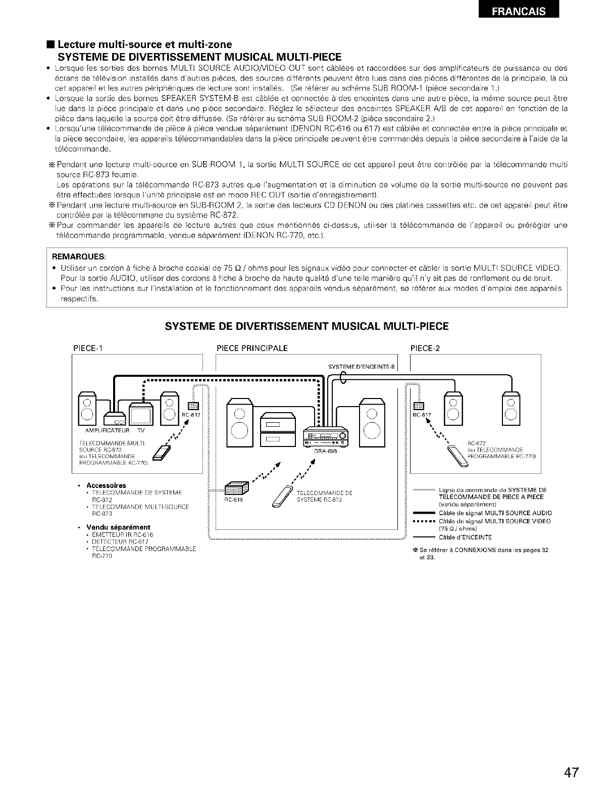
•Lecture multi-source et multi-zone
SYSTEME DE DIVERTISSEMENT MUSICAL MULTI-PIECE
•Lorsque les sorties des bornes MULTI SOURCE AUDIO/VIDEO OUT sont c_bl6es et raccord6es sur des amplificateurs de puissance ou des
6crans de t61evision install6s dans d'autres pi6ces, des sources diff6rents peuvent 6tre lues darts des pi#ces diff6rentes de la princ[pale, I&oQ
cet apparefl et les autres p6fiph6riques de lecture sont install6s. (Se r6f6rer au sch6ma SUB ROOMq (piece secondaire 1)
• Lorsque la sortie des bornes SPEAKER SYSTEM-B est cabl6e et connect6e a des enceintes dans une autre pi#ce, la m6me source peut 6tre
lue dans la pi6ce prindpale et dans une pi6ce secondaire. R6glez le s61ecteur des enceintes SPEAKER A/B de cet appareil en fonction de la
piece dans laquelle la source doit 6tre diffus6e (Se r6f6rer au schema SUB ROOM-2 (pi6ce secondaire 2.)
• Lorsqu'une t61ecommande de piece _ piece vendue s6par6ment (DENON RC-616 ou 617) est c_bl6e et connect6e entre la piece principale et
la pi6ce secondaire, les appareils t61ecommandables dans la pi6ce principaIe peuvent 6tre command6s depuis la piece secondaire a I'aide de la
t616commande.
Pendant une lecture multi-source en SUB-ROOM 1, la sortie MULTI SOURCE de cet appareil peut 6tre contr61ee par la t616commande multi
source RC-873 fournie
Les op6rations sur la t616commande RC-873 autres que I'augmentation et la diminution de volume de la sortie multi-source ne peuvent pas
6tre effectu6es Iorsque I'unit6 principale est en mode REC OUT (sortie d'enreg[strement).
Pendant une lecture multi-source en SUB-ROOM 2, la sortie des lecteurs CD DENON ou des platines cassettes etc de cet appareil peut 6tre
contr61ee par la t616commane du syst_me RC_872
Pour commander les appareils de lecture autres que ceux mentionn_s c[_dessus, utiliser la t_l_commande de I'appareil ou preregler une
t61_commande programmable, vendue s_par6ment (DENON RCW70, etc).
REMARQUES:
• Utillser un cordon a fiche a broche coaxial de 75 _ /ohms pour les signaux video pour connecter et c_bler la sortie MULTI SOURCE VIDEO.
Pour la sortie AUDIO, utlliser des cordons a fiche & broche de haute qualite d'une telle mani_re qu'il n'y ait pas de ronflement ou de bruit.
• Pour les instructions sur I'installatlon et le fonctionnement des appareils vendus s6par6ment, se ref_rer aux modes d'emploi des appareils
respectifs.
SYSTEME DE DIVERTISSEMENT MUSICAL MULTI-PIECE
PIECE-1 PIECE PRINCIPALE
AM PU FICATE UR ,q/ ,_ee •
TELECQMMANDE MULTI¸¸ _
SOURCE RC873
(ou TELECOMMANDE
PROGRAMMABLE RC 770}
•Accessoires
• TELECOMMANDE DE SYSTEME
RC 872
• TELECOMMANDE MULTI SOURCE
RC 873
• Vendu separement
• EMETTEUR IR RC-616
• DETECTEUR RC-617
• TELECOMMANDE PROGRAMMABLE
RC 770
DRA685
_ ELECOMMANDE DESYSTEME RC872
SYSTEM E D'ENCEINTE B I
PIECE-2
• RC_72
_4 Se r6f6rer a CONNEXtONS dans les pages 32
et 33.
47
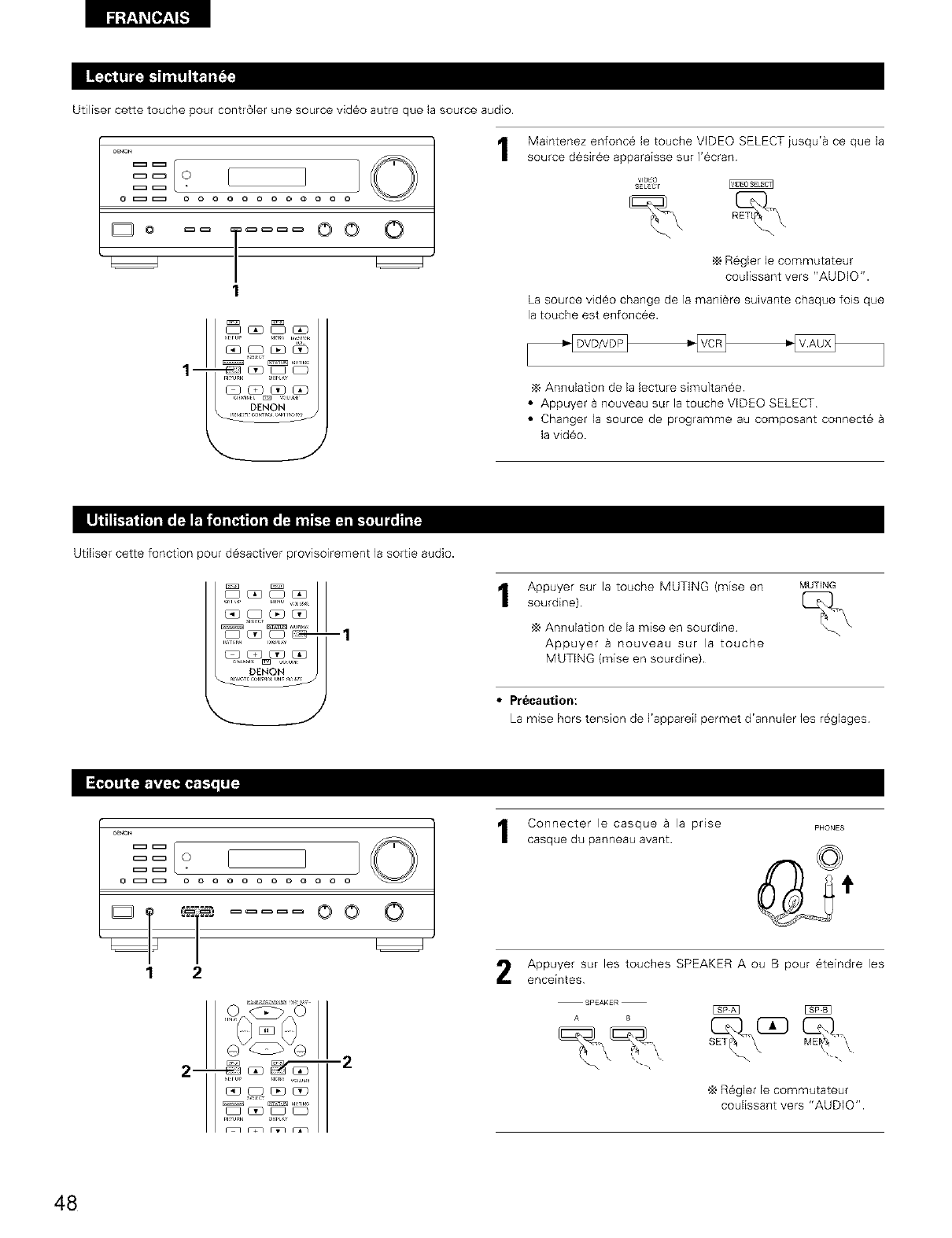
Utiliser cette touche pour contr61er une source vid6o autre que la source audio.
_ O
@_ o o o o o o o o o o
Do m oo
1
_c_c_
1- _-_ _ _ _
Maintenez enfonc6 le touche VIDEO SELECT jusqu'a ce que la
source d6sir6e apparaisse sur I'ecran
VlOEO
SELECt
,_ R6gler le commutateur
coulissant vers "AUDIO".
La source video change de ]a mani_re suivante chaque lois que
la touche est enfoncee.
Annulation de la lecture simultanee
•Appuyer a nouveau sur ]a touche VIDEO SELECT
•Changer la source de programme au composant connecte
la video.
Utiliser cette fonction pour desactiver provisoirement la sortie
-1
audio.
Appuyer sur la touche MUTING (mise en
sourdine)
Annulation de la raise en sourdine
Appuyer a nouveau sur la touche
MUTING (raise en sourdine).
MUTING
•Precaution:
La raise hors tension de I'appare[I permet d'annuler les reglages
_ O
°T "°i oo o
12
2___ -2
SHUl HH _(_U_
Connecter le casque a la prise
casque du panneau avant.
PHONES
Appuyer sur les touches SPEAKER A ou B pour _teindre les
enceintes
ES2:_
R_gler le commutateur
coulissant vers "AUDIO".
48
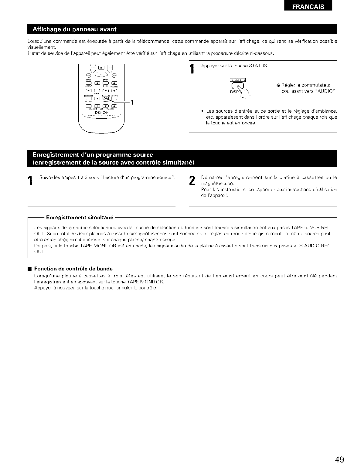
Lorsqu'une commande est 6xecut_e Bpartir de la t61_commande, cette commande 8pparatt sur 1'8ffichage, ce qui rend sa v6rification possible
visuellement.
L'6tat de service de I'appareil peut 6galement 6tre v6rifi6 sur l'affichage en utilisant la proc6dure d_crite c[-dessous
Appuyer sur 18touche STATUS.
-_ R6gler ]e commutateur
coulissant vers "AUDIO"
-1
• Les sources d'entr6e et de sortie et le r_glage d'ambiance,
etc apparaissent dans I'ordre sur I'affichage chaque fois que
la touche est enfonc_e
1Suivre les etapes 1 a 3 sous "Lecture d'un programme source". 2D_marrer I'enregistrement sur la platine a cassettes ou le
magn6toscope.
Pour les instructions, se rapporter aux instructions d'utilisation
de I'appareil
Enregistrement simultane
Les signaux de la source s61ectionn6e avec la touche de selection de fonction sont transmis simultan6ment aux prises TAPE et VCR REC
OUT. Si un total de deux platines a cassettes/magn6toscopes sont connect_s et r_gl6s en mode d'enregistrement, la m6me source peut
6tre enregistr@e simultan6ment sur chaque platine/magn6toscope
De plus, s[ la touche TAPE MONITOR est enfonc6e, les signaux audio de la plagne a cassette sont transmis aux prises VCR AUDIO REC
OUT.
• Fonction de contr61e de bande
Lorsqu'une platine a cassettes a trois t_tes est utilisee, le son r6sultant de I'enregistrement en cours peut 6tre contr616 pendant
I'enregistrement en appuyant sur la touche TAPE MONITOR
Appuyer 8 nouveau sur la touche pour annuler le contr61e
49
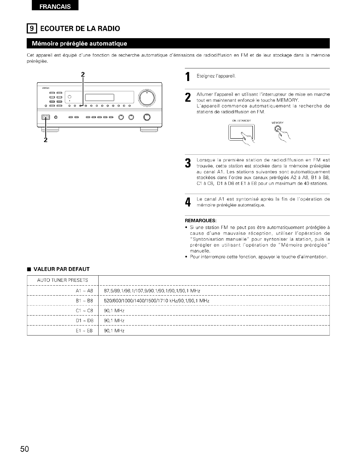
[] ECOUTER DE LA RADIO
Cet appareil est 6quip_ d'une fonction de recherche automatique d'6missions de radiodiffusion en FM et de leur stockage darts la m_moire
pr6r6gl6e.
21Eteignez I'appareil.
G I::::_ I::::_ O 0 O O 0 0 O 0
3 OO O
2
Allumer I'appareil en utilisant I'interrupteur de mise en marche
tout en maintenant enfonc_ le touche MEMORY.
L'appareil commence automatiquement la recherche de
stations de radiodiffusion en FM
ON /STANDBY
Lorsque la premiere station de radiodiffusion en FM est
trouv6e, cette station est stockee dans la m6moire pr6r6glee
au canal A1. hes stations su_vantes sont automafiquement
stock6es dans I'ordre aux canaux pr_r6gles A2 a A8, B1 BB8,
C18C8, D1 BD8etE1 a E8 pour un maximum de 40 stations
Le canal A1 est syntonis6 apr_s la fin de I'op6ration de
memoire prer6gl6e automatique
REMARQUES:
• Si une station FM ne peut pas 6tre automatiquement pr6rSgl_e
cause d'une mauvaise r6ception, utiliser I'op_ration de
"Syntonisation manuelle" pour syntoniser la station, puis la
pr6regler en utilisant I'operation de "M6moire pr_regl6e"
manuelle
• Pour interrompre cette fonction, appuyer le touche d'alimentation
•VALEUR PAR DEFAUT
AUTO TUNER PRESETS
A1 - A8 87,5/89,1/98,1/107,9/90,1/90,1/90,1/90,1 MHz
B1 - B8 520/600/1000/1400/1500/1710 kHz/90,1/90,1 MHz
C1 _ C8 90,1 MHz
D1 _ D8 90,1 MHz
E1 - E8 90,1 MHz
50
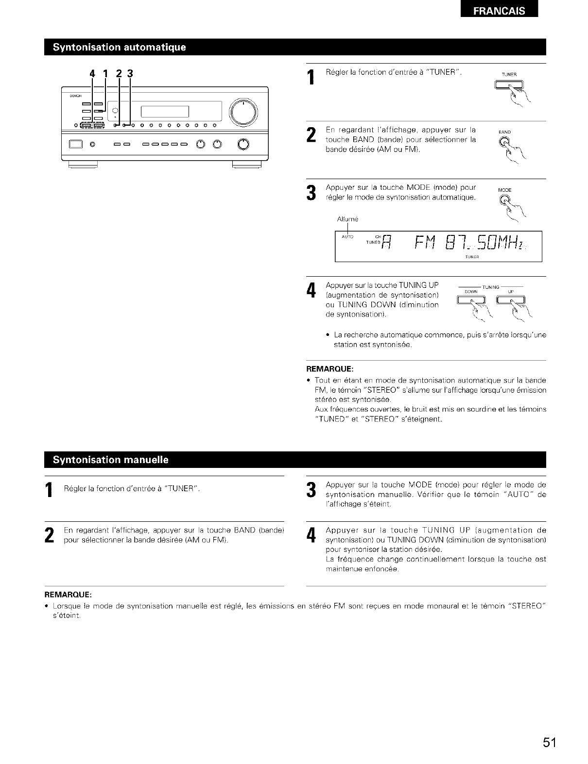
4123
oC_-_@,.) o o o o oooo
D O oo O
R_gler la fonction d'entr6e B"TUNER". TUNER
En regardant I'affichage, appuyer sur la BA_D
touche BAND (bande) pour selectionner la (_
bande d6siree (AM ou FM) %
Appuyer sur la touche MODE (mode) pour MODE
r6gler le mode de syntonisation automatique. _(_
ANume
AJTo °' -M "f C'F _A
TUNEn
Appuyer sur la toucheTUNING UP TUNING
(augmentation de syntonisatJon) oow. p
ou TUNING DOWN (diminution , ,, _
de syntonisation). _"
•La recherche automatique commence, puis s'arr6te Iorsqu'une
station est syntonisee.
REMARQUE:
•Tout elq 6tant elq mode de syntor_isation automatique sur ]a balqde
FM, le t6moin "STEREO" s'allume sur I'affichage Iorsqu'une 6mission
st6r_o est syntonis6e.
Aux fr6quences ouvertes, le bruit est mis en sourdine etles t6moins
"TUNED" et "STEREO" s'eteignent
R_gler la fonction d'entr6e B"TUNER". Appuyer sur la touche MODE (mode) pour r6gler le mode de
syntonisation manuelle Vedfier que le t6rnoin "AUTO" de
I'affichage s'eteint
En regardant I'affichage, appuyer sur la touche BAND (bande) A
pour s@lectionner la bande d6siree (AM ou FM)
Appuyer sur la touche TUNING UP (augmentation de
syntonisation) ou TUNING DOWN (diminution de syntonisation)
pour syntoniser la station d_sir6e
La fr6quence change continuellement Iorsque la touche est
maintenue enfonc6e.
REMARQUE:
• Lorsque le mode de syntonisation manuelle est r6gl_, les emissions en st6reo FM sont reques en mode monaural et le t_moin "STEREO"
s'eteint
51
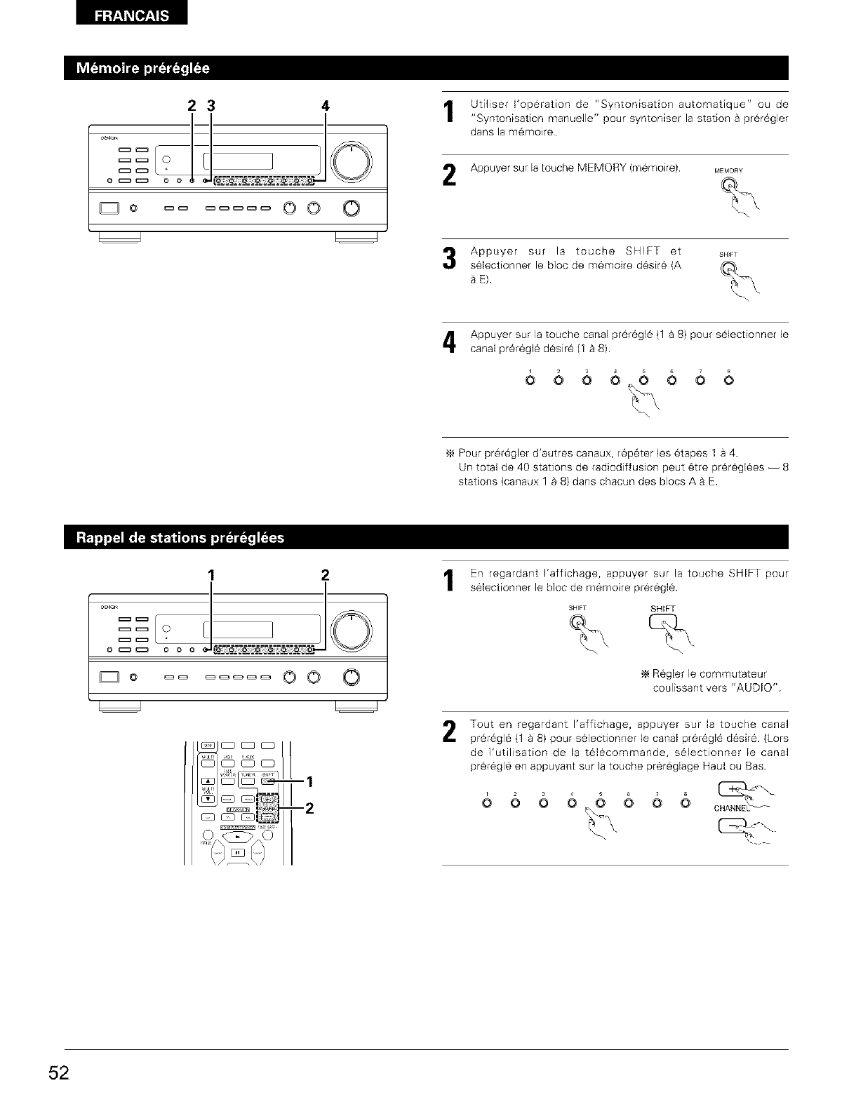
4, t Utiliser I'operation de "Syntonisafion automatique" ou de
I"Syntonisation manuelle" pour syntoniser la station a prer6gler
dans la m6moire
23
== ?[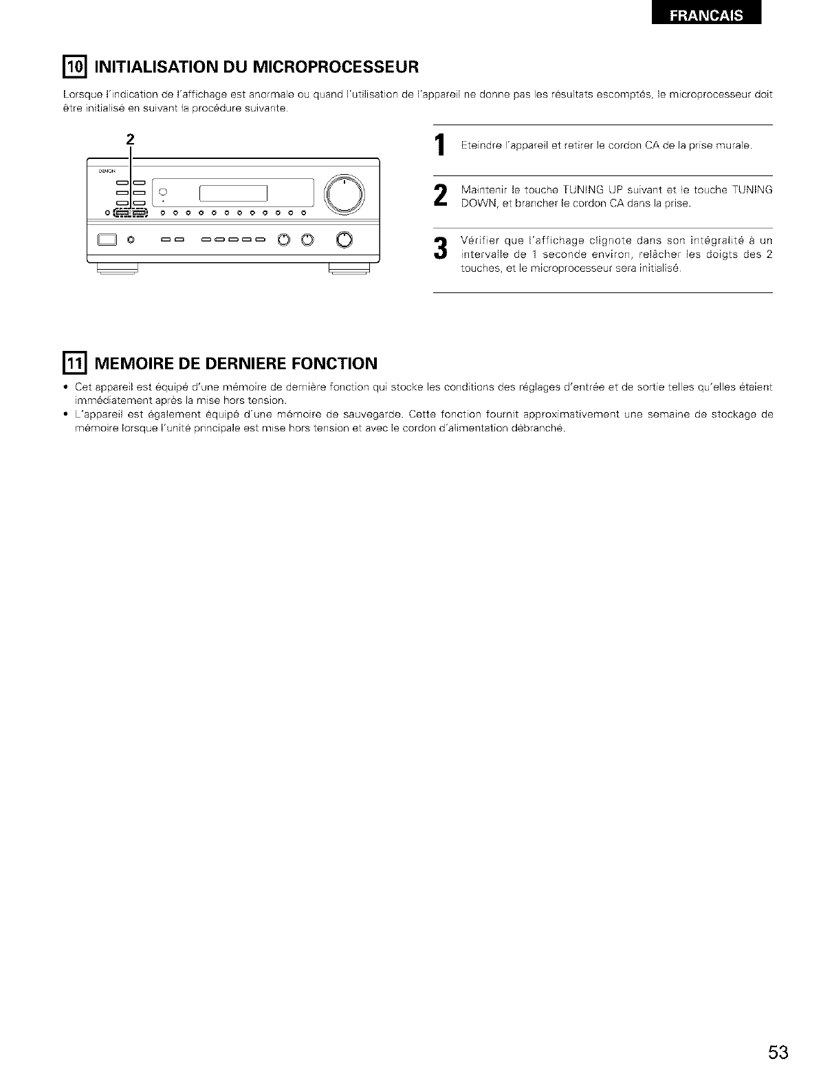
[] INITIALISATION DU MICROPROCESSEUR
Lorsque I'indication de I'affichage est anormale ou quand I'utilisation de I'appareil ne donne pas les r_sultats escompt6s, le microprocesseur doit
6tre initialise en suivant la proc6dure suivante
2
o C_::_5.'; o o o o o oo ooo
Do OO O
Eteindre I'appareil et retirer le cordon CA de la prise murale.
Maintenir le touche TUNING UP suivant et le touche TUNING
DOWN, et brancher le cordon CA dans la pnse
V_rifier que I'affichage clignote dans son int6gralit6 Bun
intervalle de 1 seconde environ, rel_cher les doigts des 2
touches, et le microprocesseur sera initialise
[] MEMOIRE DE DERNIERE FONCTION
•Cet appareil est equip6 d'une m6moire de derni_re fonction qui stocke les conditions des r6glages d'entr6e et de sortie telles qu'elles _taient
imm6diatement apr6s la raise hors tension.
•L'appareil est egalement _quip6 d'une memoire de sauvegarde. Cette fonction fournit approximativement une semaine de stockage de
memoire Iorsque I'unit_ principale est raise hors tension et avec le cordon d'alimentation debranch6.
53
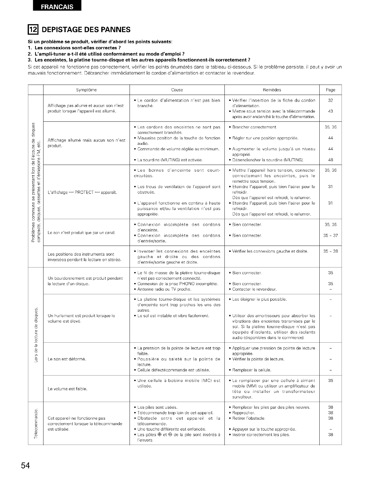
[] DEPISTAGE DES PANNES
Si un probleme se produit, verifier d'abord les points suivants:
1. Les connexions sont-elles correctes ?
2. L'ampli-tuner a-t-il ete utilise conformement au mode d'emploi ?
3. Les enceintes, la platine tourne-disque et les autres appareils fonctionnent41s correctement ?
Si cet appareil ne fonctionne pas correctement, v6rifler les points 6num6r6s darts le tableau ci-dessous. Si le probl_me persiste, il peut y avoir un
mauvais fonctionnement Debrancher imm6diatement le cordon d'alimentation et contacter le revendeur.
4
o-
o_
s
Sympt6me Cause Remedes Page
• Le cordon d'alimentation n'est pas bier * Verifier I'insertion de la fiche du cordon 32
Affichage pas allume et aucun son n'est branche d'alimentation
produit Iorsque I'appareil est allume * Mettre SOdStension avec ia telecommande 43
apres avoir enclenche la touche d'alimentation
• Les cordons des enceintes ne SORt pas * arancher correctement 35, 36
correctement branches
Aff chage allume maEs aucun son n'est • Mauvaise postion de la touche de fonction * Regler surune pos tion appropr ee 44
produit audio
• Commande de volume rsglse au minimum * Augmenter le volume jusqu'a un nveau 44
appropde
• La sourdine (MUTING) est act vee * Desenclencher la sourdine (MUTING) 48
• Les bornes d'enceinte SORt court- 35,36
circukees
L'aff chage -- PROTECT -- apparait
• Les trous de ventilat on de I'appareil SORt
obstrues
• Mettre I'appareil hors tension, connecter
correctement les enceintes, puis le
remettre SOdStension
• Eteindre I'appareil, puis bier I'aerer pour le
refroid r
Des que I'appareil est refroidi, le rallumer
• Eteindre I'appareil, puis bier I'aerer pour le
refroid r
Des que I'appareil est refroidi, le rallumer
31
• L'appareil fo_ctionne en continu a haute 31
puissance et/ou la ve_tilation n'est pas
appropdee
• Connexion incomplete des cordons • Bienconnecter 35,36
d'enceinte
Le son n'est produit que par un canal • Connexion incomplete des cordons • Bienconnecter 35_37
d'entree/sort e
• Inverser les connexions des enceintes • Verifier les connexions gauche et droite 35 _ 39
Les positions des nstrumentssont gauche et droite ou des cordons
inversees pendant la lecture en stereo d'entree/sort e gauche et droite
• Le fil de masse de la platine toume-disque • BieR connecter 35
Un bourdonnement est produit pendant n'est pas correctement connecte
la lecture d'un disque • Connexion de la prise PHONO incomplete • BieR connecter 35
• Antenne radio ou TV proche • Contacter le revendeur
• La platine tourne-disque et les systemes • Les eloigner le plus possible
d'enceinte SORt trop proches les uns des
autres
_- Un hudement est produit Iorsque le • Le sol est instable et vibre facilement • Utiliser des amortisseurs pour absorber les
volume est eleve vibrations des enceintes transmises par le
sol Si la platine tourne-disque n'est pas
6qu_pse d'solantSr utilser des isolants
audio (disponibles darts le commerce)
• La pression de la pointe de lecture est trop • Appliquer une press on de pointe de lecture
faible appropdee
Le son estdeforme • Poussiere ou salete sur la pointe de •Vedfierlaponte delecture
lecture
• CelUe defectecommande est utilisee • Remplacer la cellule
• Une cellule a bobine mobile (MC) est • La remplacer par une cellule a aimant 35
ut lisee mobile (MM) ou utiliser un amplificateur de
Levolumeestfaible t6te ou installer un transformateur
survolteur
• Les piles SORt usees Remplacer les pileo par des piles neuves 38
• Telecommande trop loin de cet appareil • Rapprocher 38
Cetappareilnefonctionnepas •Obstacle entre cet appareil et la • Retirerl'obstacle 38
E correctement Iorsque la telecommande tel6commande
est utilisee • Une touche differente est enfoncee • Appuyer sur la touche appropriee
• Les p61es (_ et e de la pile SORt inseres a • Inserer correctement les piles 38
I'envers
54
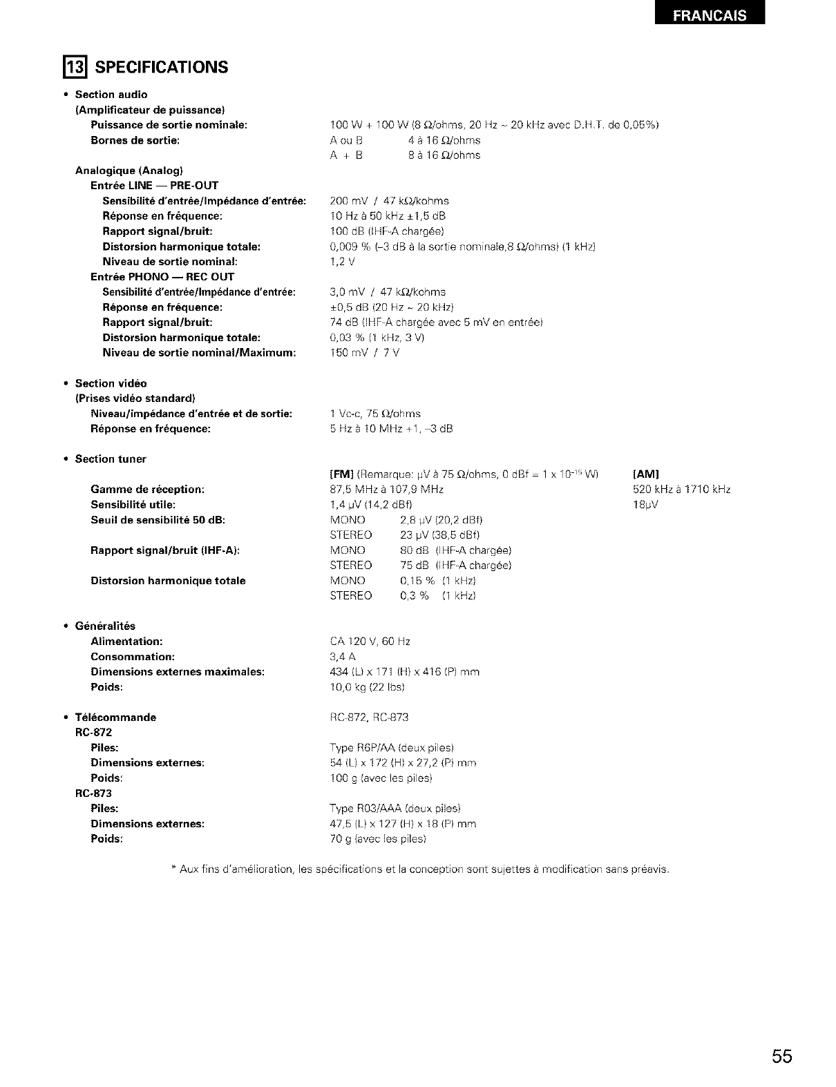
[] SPECIFICATIONS
•Section audio
(Amplificateur de puissance)
Puissance de sortie nominale:
Bornes de sortie:
Analogique (Analog)
Entree LINE -- PRE-OUT
Sensibilit_ d'entree/Imp_dance d'entr_e:
R_ponse en frequence:
Rapport signal/bruit:
Distorsion harmonique totale:
Niveau de sortie nominal:
Entree PHONO -- REC OUT
Sensibilite d'entr_e/Impedance d'entree:
R_ponse en frequence:
Rapport signal/bruit:
Distorsion harmonique totale:
Niveau de sortie nominal/Maximum:
100 W + 100 W (8 _/ohms, 20 Hz - 20 kHz avec D.HT. de 0,05%)
Aou B 44 16 _/ohms
A + B 88 16_/ohms
200 mV /47 k_/kohms
10 Hz _ 50 kHz +1,5 dB
100 dB (IHF-A charg6e)
0,009 % (-3 dB a la sortie nominale,8 _2/ohms) (1 kHz)
1,2V
3,0 mV /47 k£)./kohms
+0,5 dB (20 Hz - 20 kHz)
74 dB (IHF_A chargee avec 5 mV en entr6e)
0,03 % (1 kHz, 3 V)
150mV /7V
•Section video
(Prises video standard)
Niveau/imp_dance d'entrde et de sortie:
Reponse en frequence:
1 Vc-c, 75 _/ohms
5 Hz B10 MHz +1, -3 dB
•Section tuner
Gamme de reception:
Sensibilite utile:
Seuil de sensibilit_ 50 dB:
Rapport signal/bruit (IHF-A):
Distorsion harmonique totale
[FM] (Remarque: pV a 75 £_/ohms, 0 dBf 1 x 10 _"W)
87,5 MHza 107,9 MHz
1,4 #V (14,2 dBf)
MONO 2,8 pV (20,2 dBf)
STEREO 23 pV (38,5 dBf)
MONO 80dB (]HF-A chargee)
STEREO 75 dB (IHF-A chargee)
MONO 0,15% (1 kHz)
STEREO 0,3 % (1 kHz)
[AM]
520 kHza 1710 kHz
18pV
•Generalites
Alimentation:
Consommation:
Dimensions externes maximales:
Poids:
CA 120 V, 60 Hz
3,4 A
434 (L) x 171 (H) x 416 (P) mm
10,0 kg (22 Ibs)
•Telecommande
RC-872
Piles:
Dimensions externes:
Poids:
RC-873
Piles:
Dimensions externes:
Poids:
RC-872, RC_873
Type R6P/AA (deux piles)
54 (L) x 172 (H) x 27,2 (P) mm
100 g (avec les piles)
Type R03/AAA (deux piles)
47,5 (L) x 127 (H) x I8 (P) mm
70 g (avec les piles)
* Aux fins d'am61ioration, les sp6ciflcations et la conception sont sujettes a modification sans preavis
55

NIPPON COLUMBIA CO., LTD.
14 14, AKASAKA 4-CHOME, MINATO KU, TOKYO 107 8011, JAPAN
Telephone: (03) 3584 8111
Cable: NIPPON COLUMBIA TOKYO Telex: JAPANOLA J22591
Printed in Korea 511 3580 108
