Denon Dn X1500 Users Manual
DN-X1500 to the manual 2ece92ce-de2b-4289-abdb-bf42c876112a
2015-01-23
: Denon Denon-Dn-X1500-Users-Manual-221475 denon-dn-x1500-users-manual-221475 denon pdf
Open the PDF directly: View PDF ![]() .
.
Page Count: 23
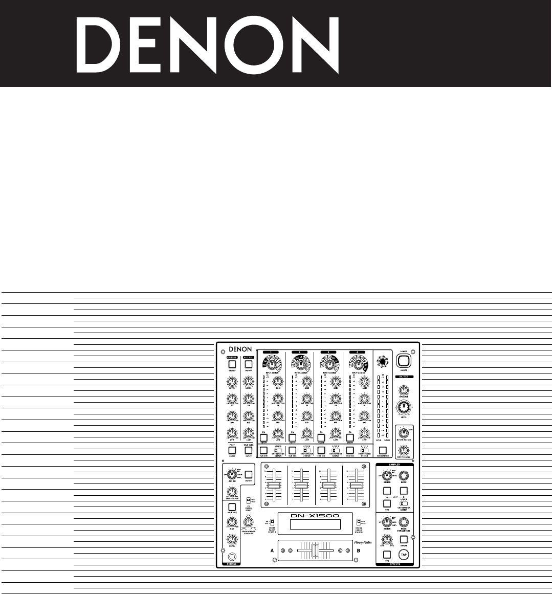
DJ MIXER
DN-X1500
OPERATING INSTRUCTIONS
INSTRUCCIONES DE OPERACION
FOR ENGLISH READERS PAGE 2 ~ PAGE 13
PARA LECTORES DE ESPANOL PAGINA 14 ~ PAGINA 22
2
CAUTION: TO REDUCE THE RISK OF ELECTRIC SHOCK, DO NOT REMOVE COVER (OR
BACK). NO USER SERVICEABLE PARTS INSIDE. REFER SERVICING TO
QUALIFIED SERVICE PESONNEL.
The lightning flash with arrowhead symbol, within an equilateral triangle, is intended to
alert the user to the presence of uninsulated “dangerous voltage” within the product’s
enclosure that may be of sufficient magnitude to constitute a risk of electric shock to
persons.
The exclamation point within an equilateral triangle is intended to alert the user to the
presence of important operating and maintenance (servicing) instructions in the literature
accompanying the appliance.
WARNING: TO PREVENT FIRE OR SHOCK HAZARD, DO NOT EXPOSE THIS
APPLIANCE TO RAIN OR MOISTURE.
CAUTION:
1. Handle the power supply cord carefully
Do not damage or deform the power supply cord. If it
is damaged or deformed, it may cause electric shock
or malfunction when used. When removing from wall
outlet, be sure to remove by holding the plug
attachment and not by pulling the cord.
2. Do not open the top cover
In order to prevent electric shock, do not open the top
cover.
If problems occur, contact your DENON dealer.
3. Do not place anything inside
Do not place metal objects or spill liquid inside the DJ
mixer.
Electric shock or malfunction may result.
Please, record and retain the Model name and serial
number of your set shown on the rating label.
Model No. DN-X1500 Serial No.
This device complies with Part 15 of the FCC Rules.
Operation is subject to the following two conditions:
(1) This device may not cause harmful interference,
and (2) this device must accept any interference
received, including interference that may cause
undesired operation.
This Class B digital apparatus meets all requirements
of the Canadian Interference-Causing Equipment
Regulations.
Cet appareil numérique de la classe B respecte toutes
les exigences du Règlement sur le matériel brouilleur
du Canada.
CAUTION
TO PREVENT ELECTRIC SHOCK, MATCH
WIDE BLADE OF PLUG TO WIDE SLOT,
FULLY INSERT.
ATTENTION
POUR ÉVITER LES CHOCS ÉLECTRIQUES,
INTERODUIRE LA LAME LA PLUS LARGE
DE LA FICHE DANS LA BORNE
CORRESPONDANTE DE LA PRISE ET
POUSSER JUSQU’ AU FOND.
CAUTION
RISK OF ELECTRIC SHOCK
DO NOT OPEN
LABELS:
SAFETY INSTRUCTIONS
1. Read Instructions – All the safety and operating instructions
should be read before the product is operated.
2. Retain Instructions – The safety and operating instructions
should be retained for future reference.
3. Heed Warnings – All warnings on the product and in the
operating instructions should be adhered to.
4. Follow Instructions – All operating and use instructions
should be followed.
5. Cleaning – Unplug this product from the wall outlet before
cleaning. Do not use liquid cleaners or aerosol cleaners.
6. Attachments – Do not use attachments not recommended
by the product manufacturer as they may cause hazards.
7. Water and Moisture – Do not use this product near water –
for example, near a bath tub, wash bowl, kitchen sink, or
laundry tub; in a wet basement; or near a swimming pool;
and the like.
8. Accessories – Do not place this product on an unstable cart,
stand, tripod, bracket, or table. The product may fall,
causing serious injury to a child or adult, and serious
damage to the product. Use only with a cart, stand, tripod,
bracket, or table recommended by the manufacturer, or
sold with the product. Any mounting of the product should
follow the manufacturer’s instructions, and should use a
mounting accessory
recommended by the
manufacturer.
9. A product and cart
combination should be
moved with care. Quick
stops, excessive force,
and uneven surfaces may
cause the product and cart
combination to overturn.
10. Ventilation – Slots and openings in the cabinet are provided
for ventilation and to ensure reliable operation of the
product and to protect it from overheating, and these
openings must not be blocked or covered. The openings
should never be blocked by placing the product on a bed,
sofa, rug, or other similar surface. This product should not
be placed in a built-in installation such as a bookcase or rack
unless proper ventilation is provided or the manufacturer’s
instructions have been adhered to.
11. Power Sources – This product should be operated only
from the type of power source indicated on the marking
label. If you are not sure of the type of power supply to
your home, consult your product dealer or local power
company. For products intended to operate from battery
power, or other sources, refer to the operating instructions.
12. Grounding or Polarization – This product may be equipped
with a polarized alternating-current line plug (a plug having
one blade wider than the other). This plug will fit into the
power outlet only one way. This is a safety feature. If you
are unable to insert the plug fully into the outlet, try
reversing the plug. If the plug should still fail to fit, contact
your electrician to replace your obsolete outlet. Do not
defeat the safety purpose of the polarized plug.
13. Power-Cord Protection – Power-supply cords should be
routed so that they are not likely to be walked on or pinched
by items placed upon or against them, paying particular
attention to cords at plugs, convenience receptacles, and
the point where they exit from the product.
15. Outdoor Antenna Grounding – If an outside antenna or
cable system is connected to the product, be sure the
antenna or cable system is grounded so as to provide some
protection against voltage surges and built-up static
charges. Article 810 of the National Electrical Code,
ANSI/NFPA 70, provides information with regard to proper
grounding of the mast and supporting structure, grounding
of the lead-in wire to an antenna discharge unit, size of
grounding conductors, location of antenna-discharge unit,
connection to grounding electrodes, and requirements for
the grounding electrode. See Figure A.
16. Lightning – For added protection for this product during a
lightning storm, or when it is left unattended and unused
for long periods of time, unplug it from the wall outlet and
disconnect the antenna or cable system. This will prevent
damage to the product due to lightning and power-line
surges.
17. Power Lines – An outside antenna system should not be
located in the vicinity of overhead power lines or other
electric light or power circuits, or where it can fall into such
power lines or circuits. When installing an outside antenna
system, extreme care should be taken to keep from
touching such power lines or circuits as contact with them
might be fatal.
18. Overloading – Do not overload wall outlets, extension
cords, or integral convenience receptacles as this can result
in a risk of fire or electric shock.
19. Object and Liquid Entry – Never push objects of any kind
into this product through openings as they may touch
dangerous voltage points or short-out parts that could
result in a fire or electric shock. Never spill liquid of any
kind on the product.
20. Servicing – Do not attempt to service this product yourself
as opening or removing covers may expose you to
dangerous voltage or other hazards. Refer all servicing to
qualified service personnel.
21. Damage Requiring Service – Unplug this product from the
wall outlet and refer servicing to qualified service personnel
under the following conditions:
a) When the power-supply cord or plug is damaged,
b) If liquid has been spilled, or objects have fallen into the
product,
c) If the product has been exposed to rain or water,
d) If the product does not operate normally by following
the operating instructions. Adjust only those controls
that are covered by the operating instructions as an
improper adjustment of other controls may result in
damage and will often require extensive work by a
qualified technician to restore the product to its normal
operation,
e) If the product has been dropped or damaged in any way,
and
f) When the product exhibits a distinct change in
performance – this indicates a need for service.
22. Replacement Parts – When replacement parts are required,
be sure the service technician has used replacement parts
specified by the manufacturer or have the same
characteristics as the original part. Unauthorized
substitutions may result in fire, electric shock, or other
hazards.
23. Safety Check – Upon completion of any service or repairs
to this product, ask the service technician to perform safety
checks to determine that the product is in proper operating
condition.
24. Wall or Ceiling Mounting – The product should be mounted
to a wall or ceiling only as recommended by the
manufacturer.
25. Heat – The product should be situated away from heat
sources such as radiators, heat registers, stoves, or other
products (including amplifiers) that produce heat.
FIGURE A
EXAMPLE OF ANTENNA GROUNDING
AS PER NATIONAL
ELECTRICAL CODE ANTENNA
LEAD IN
WIRE
GROUND
CLAMP
ELECTRIC
SERVICE
EQUIPMENT
ANTENNA
DISCHARGE UNIT
(NEC SECTION 810-20)
GROUNDING CONDUCTORS
(NEC SECTION 810-21)
GROUND CLAMPS
POWER SERVICE GROUNDING
ELECTRODE SYSTEM
(NEC ART 250, PART H)
NEC - NATIONAL ELECTRICAL CODE
3
ENGLISH
@1
@3
#2
#1
#3 q
w
e
r
t
y
!4
!2
!0 !1
!3
o
ui
!6@0 !8!9 !5!7 !7
#5
#6
#5
#6
#5
#6
#5
#6
#4 #7
#0
@7 @8
@5 @6
@4
@9
@2
#9 #9 #9 #9
#8 #8 #8 #8
!6 !6 !6 !6
!0
Unit: mm
Gerät: mm
Unité: mm
Unità: mm
Unidad: mm
Toestel: mm
Enhet: mm
單位:mm
ESPAÑOL
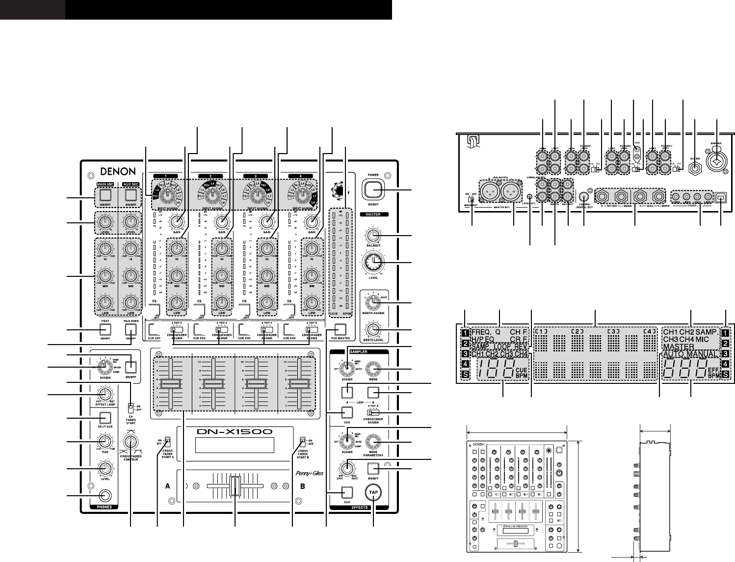
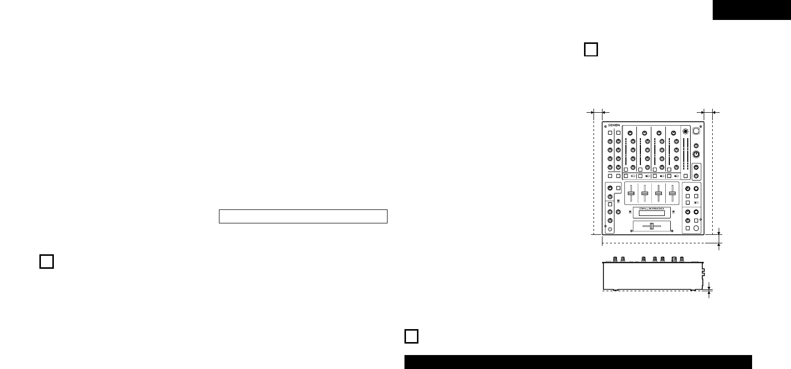
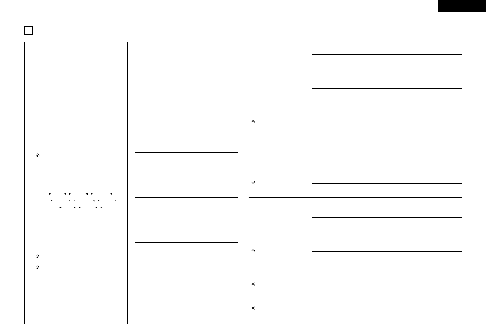
TOP PANEL DIAGRAM / DIAGRAMA DEL PANEL SUPERIOR
DISPLAY / VISUALIZADOR
REAR PANEL DIAGRAM / DIAGRAMA DEL PANEL POSTERIOR
%5 %4 %2
%3 %1
%0 $9 $8 $7 $6
$0
$0
$0
$1 $0
$1
$3 $0
$1 $4 $5$2 $2
$2
^4^5 ^2^3
%6 %9 ^0 ^1%7 %8
327 (12-7/8”)
310 (12-13/64”) 90
(3-35/64”)
20
(25/32”)
4
•DECLARATION OF CONFORMITY
We declare under our sole responsibility that this
product, to which this declaration relates, is in
conformity with the following standards:
EN60065, EN55013, EN55020, EN61000-3-2 and
EN61000-3-3.
Following the provisions of 73/23/EEC,
89/336/EEC and 93/68/EEC Directive.
•ÜBEREINSTIMMUNGSERKLÄRUNG
Wir erklären unter unserer Verantwortung, daß
dieses Produkt, auf das sich diese Erklärung
bezieht, den folgenden Standards entspricht:
EN60065, EN55013, EN55020, EN61000-3-2 und
EN61000-3-3.
Entspricht den Verordnungen der Direktive
73/23/EEC, 89/336/EEC und 93/68/EEC.
•DECLARATION DE CONFORMITE
Nous déclarons sous notre seule responsabilité
que l’appareil, auquel se réfère cette déclaration,
est conforme aux standards suivants:
EN60065, EN55013, EN55020, EN61000-3-2 et
EN61000-3-3.
D’après les dispositions de la Directive
73/23/EEC, 89/336/EEC et 93/68/EEC.
•DICHIARAZIONE DI CONFORMITÀ
Dichiariamo con piena responsabilità che questo
prodotto, al quale la nostra dichiarazione si
riferisce, è conforme alle seguenti normative:
EN60065, EN55013, EN55020, EN61000-3-2 e
EN61000-3-3.
In conformità con le condizioni delle direttive
73/23/EEC, 89/336/EEC e 93/68/EEC.
QUESTO PRODOTTO E’ CONFORME
AL D.M. 28/08/95 N. 548
•DECLARACIÓN DE CONFORMIDAD
Declaramos bajo nuestra exclusiva
responsabilidad que este producto al que hace
referencia esta declaración, está conforme con
los siguientes estándares:
EN60065, EN55013, EN55020, EN61000-3-2 y
EN61000-3-3.
Siguiendo las provisiones de las Directivas
73/23/EEC, 89/336/EEC y 93/68/EEC.
•EENVORMIGHEIDSVERKLARING
Wij verklaren uitsluitend op onze
verantwoordelijkheid dat dit produkt, waarop
deze verklaring betrekking heeft, in
overeenstemming is met de volgende normen:
EN60065, EN55013, EN55020, EN61000-3-2 en
EN61000-3-3.
Volgens de bepalingen van de Richtlijnen
73/23/EEC, 89/336/EEC en 93/68/EEC.
•ÖVERENSSTÄMMELSESINTYG
Härmed intygas helt på eget ansvar att denna
produkt, vilken detta intyg avser, uppfyller
följande standarder:
EN60065, EN55013, EN55020, EN61000-3-2 och
EN61000-3-3.
Enligt stadgarna i direktiv 73/23/EEC, 89/336/EEC
och 93/68/EEC.
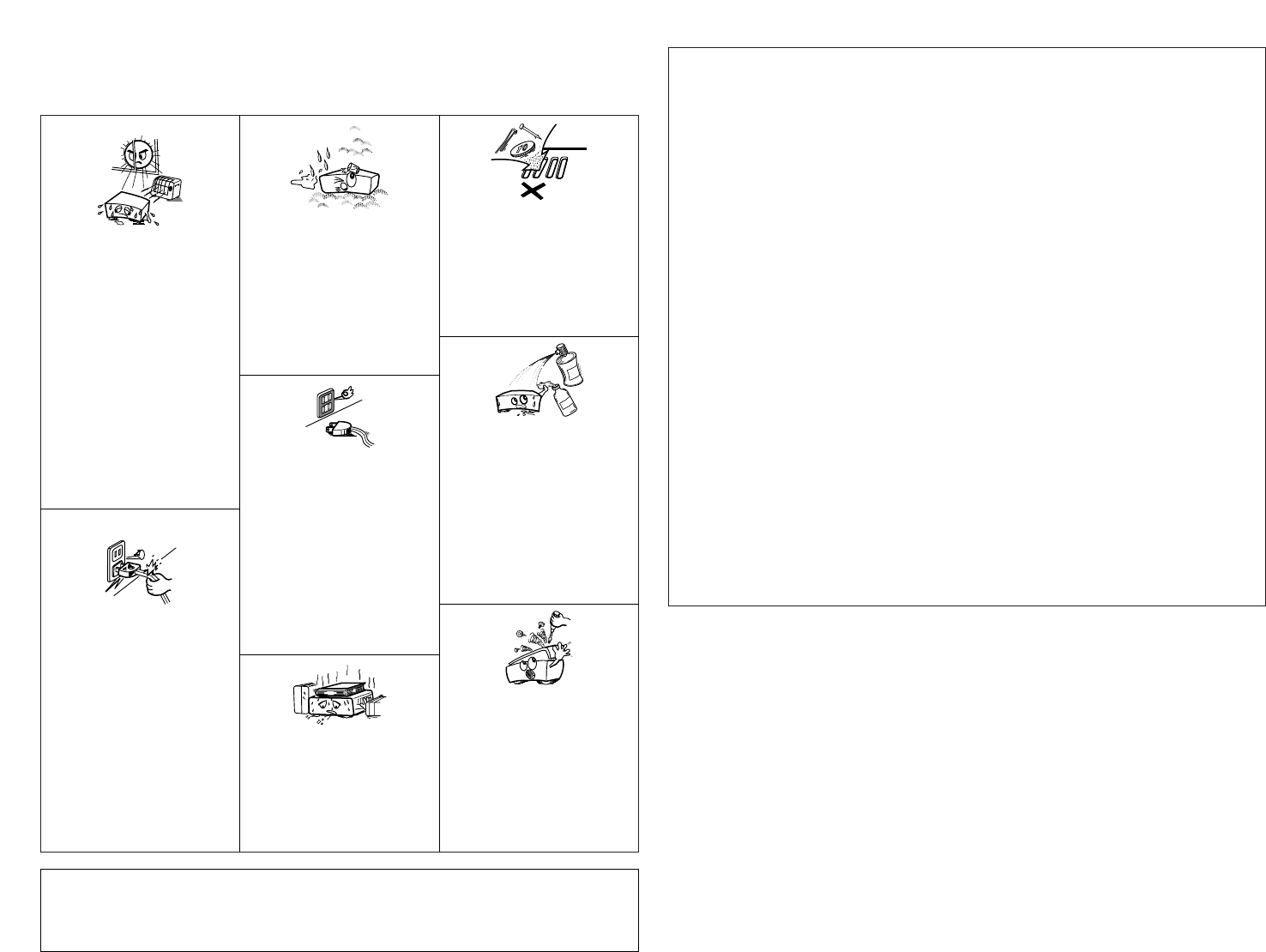
NOTE ON USE / HINWEISE ZUM GEBRAUCH /
OBSERVATIONS RELATIVES A L’UTILISATION / NOTE SULL’USO
NOTAS SOBRE EL USO / ALVORENS TE GEBRUIKEN / OBSERVERA
•Avoid high temperatures.
Allow for sufficient heat dispersion when
installed on a rack.
•Vermeiden Sie hohe Temperaturen.
Beachten Sie, daß eine ausreichend
Luftzirkulation gewährleistet wird, wenn das
Gerät auf ein Regal gestellt wird.
•Eviter des températures élevées
Tenir compte d’une dispersion de chaleur
suffisante lors de l’installation sur une
étagère.
•Evitate di esporre l’unità a temperature alte.
Assicuratevi che ci sia un’adeguata
dispersione del calore quando installate
l’unità in un mobile per componenti audio.
•Evite altas temperaturas
Permite la suficiente dispersión del calor
cuando está instalado en la consola.
•Vermijd hoge temperaturen.
Zorg voor een degelijk hitteafvoer indien het
apparaat op een rek wordt geplaatst.
•Undvik höga temperaturer.
Se till att det finns möjlighet till god
värmeavledning vid montering i ett rack.
•Keep the set free from moisture, water, and
dust.
•Halten Sie das Gerät von Feuchtigkeit,
Wasser und Staub fern.
•Protéger l’appareil contre l’humidité, l’eau et
lapoussière.
•Tenete l’unità lontana dall’umidità, dall’acqua
e dalla polvere.
•Mantenga el equipo libre de humedad, agua
y polvo.
•Laat geen vochtigheid, water of stof in het
apparaat binnendringen.
•Utsätt inte apparaten för fukt, vatten och
damm.
•Do not let foreign objects in the set.
•Keine fremden Gegenstände in das Gerät
kommen lassen.
•Ne pas laisser des objets étrangers dans
l’appareil.
•E’ importante che nessun oggetto è inserito
all’interno dell’unità.
•No deje objetos extraños dentro del equipo.
•Laat geen vreemde voorwerpen in dit
apparaat vallen.
•Se till att främmande föremål inte tränger in i
apparaten.
•Do not let insecticides, benzene, and thinner
come in contact with the set.
•Lassen Sie das Gerät nicht mit Insektiziden,
Benzin oder Verdünnungsmitteln in
Berührung kommen.
•Ne pas mettre en contact des insecticides,
du benzène et un diluant avec l’appareil.
•Assicuratevvi che l’unità non venga in
contatto con insetticidi, benzolo o solventi.
•No permita el contacto de insecticidas,
gasolina y diluyentes con el equipo.
•Laat geen insektenverdelgende middelen,
benzine of verfverdunner met dit apparaat in
kontakt komen.
•Se till att inte insektsmedel på spraybruk,
bensen och thinner kommer i kontakt med
apparatens hölje.
•Unplug the power cord when not using the
set for long periods of time.
•Wenn das Gerät eine längere Zeit nicht
verwendet werden soll, trennen Sie das
Netzkabel vom Netzstecker.
•Débrancher le cordon d’alimentation lorsque
l’appareil n’est pas utilisé pendant de
longues périodes.
•Disinnestate il filo di alimentazione quando
avete l’intenzione di non usare il filo di
alimentazione per un lungo periodo di tempo.
•Desconecte el cordón de energía cuando no
utilice el equipo por mucho tiempo.
•Neem altijd het netsnoer uit het stopkontakt
wanneer het apparaat gedurende een lange
periode niet wordt gebruikt.
•Koppla ur nätkabeln om apparaten inte
kommer att användas i lång tid.
•Do not obstruct the ventilation holes.
•Die Belüftungsöffnungen dürfen nicht
verdeckt werden.
•Ne pas obstruer les trous d’aération.
•Non coprite i fori di ventilazione.
•No obstruya los orificios de ventilación.
•De ventilatieopeningen mogen niet worden
beblokkeerd.
•Täpp inte till ventilationsöppningarna.
•Handle the power cord carefully.
Hold the plug when unplugging the cord.
•Gehen Sie vorsichtig mit dem Netzkabel um.
Halten Sie das Kabel am Stecker, wenn Sie
den Stecker herausziehen.
•Manipuler le cordon d’alimentation avec
précaution.
Tenir la prise lors du débranchement du
cordon.
•Manneggiate il filo di alimentazione con cura.
Agite per la spina quando scollegate il cavo
dalla presa.
•Maneje el cordón de energía con cuidado.
Sostenga el enchufe cuando desconecte el
cordón de energía.
•Hanteer het netsnoer voorzichtig.
Houd het snoer bij de stekker vast wanneer
deze moet worden aan- of losgekoppeld.
•Hantera nätkabeln varsamt.
Håll i kabeln när den kopplas från el-uttaget.
•Never disassemble or modify the set in any
way.
•Versuchen Sie niemals das Gerät
auseinander zu nehmen oder auf jegliche Art
zu verändern.
•Ne jamais démonter ou modifier l’appareil
d’une manière ou d’une autre.
•Non smontate mai, nè modificate l’unità in
nessun modo.
•Nunca desarme o modifique el equipo de
ninguna manera.
•Nooit dit apparaat demonteren of op andere
wijze modifiëren.
•Ta inte isär apparaten och försök inte bygga
om den.
✽(For sets with ventilation holes)
CAUTION
•The ventilation should not be impeded by covering the
ventilation openings with items, such as newspapers,
table-cloths, curtains, etc.
•No naked flame sources, such as lighted candles,
should be placed on the apparatus.
•Please be care the environmental aspects of battery
disposal.
•The apparatus shall not be exposed to dripping or
splashing for use.
•No objects filled with liquids, such as vases, shall be
placed on the apparatus.
5
ENGLISH
1
MAIN FEATURES
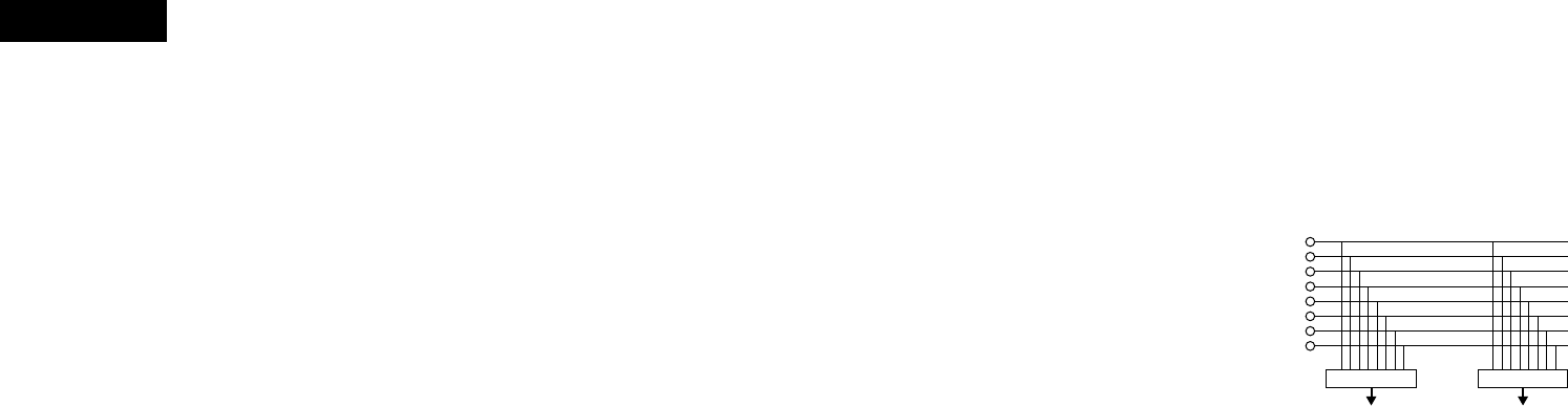
1. Matrix input assignment
8 input sources is freely assignable to each
channels.
2. Penny & Giles Crossfader
Smooth and reliable mixing is excelled by Penny &
Giles Crossfader.
3. Sampler
On-board digital Sampler can record up to 8
seconds CD quality sound. You can seamlessly
Loop this Sampler or play it backwards
(REVERSE). The pitch and output level of Sampler
can be adjusted independently.
4. Internal Effector
Various sound effects can be performed. (DELAY,
ECHO, PAN, TRANS, FILTER, FLANGER, KEY)
5. Auto BPM counter, BPM Lock, TAP and Manual
BPM input
In addition to an Auto BPM counter and Tap
function, the DN-X1500 is also equipped with the
temporarily Lock function of the Auto BPM
counter and the Manual BPM input function.
6. Channel Fader and Crossfader Start
The CD player can be started or stopped simply by
increasing or decreasing the level of the Ch. Fader
or by using the Crossfader left to right or right to
left. (This function can only be used when the
DENON CD players DN-S3000, DN-S5000, DN-
D6000 or etc. is connected to the DN-X1500.)
7. Digital output
The DN-X1500 allows you to record directly to CD-
R, MiniDisc or a hard disk device through it’s
exclusive coaxial digital output.
The digital output maintains a constant 44.1 kHz
signal.
8. Enhanced SEND/RETURN terminals
8 LINE, 3 PHONO, 2 Microphone systems, 2
MASTER outputs, BOOTH output and REC output
are provided independently. Effect SEND/RETURN
terminals are also provided for a external effects
processor.
9. 3-Band equalizer/gain
LOW, MID, HI and GAIN controls are available on
every input channel.
10. Crossfader Contour
This feature allows adjusting the “shape” of the
Crossfader response from a gentle curve for
smooth, long running fades, to the steep pitch
required for top performance cut and scratch
effects.
11. Mic Post
This feature will pass the Mic signal into the
BOOTH, REC output and DIGITAL output signal
path.
In the OFF mode, the Mic signal will not be routed
through the above outputs.
2INSTALLATION
When the DN-X1500 is installed inside a coffin or DJ
booth, separate it from the foam (sponge), walls or
other equipment to improve heat radiation.
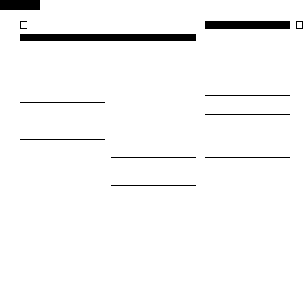
3PART NAMES AND FUNCTIONS (Refer to page 3.)
(1) Top panel
qPower operation switch (POWER)
• The power turns on when the button is
switched from the off position (£) to the on
position (¢).
• The power turns off when the button is
switched from the on position (¢) to the off
position (£).
wMASTER BALANCE control
• Adjusts the L/R balance of the MASTER output.
eMASTER LEVEL control
• Adjusts the level of the MASTER outputs.
rBOOTH ASSIGN switch
• Selects the source of the BOOTH output.
tBOOTH LEVEL control
• Adjusts the level of the BOOTH output.
ySAMPLER ASSIGN switch
• Use this to select the source for Sampler
recording.
uSAMPLER MODE knob
• Use this to set the Sampler playback mode or
edit the Sampler.
• Push this knob during the Sampler playback or
recording, the Sampler playback or recording is
stopped.
iSAMPLER A button
• Push this button, the Sampler recording or
playback starts.
oSAMPLER B button
• Use this to set the Sampler B point.
Min. 2 cm
– TABLE OF CONTENTS –
zMAIN FEATURES ...............................................5
xINSTALLATION...................................................5
cPART NAMES AND FUNCTIONS ................5 ~ 7
vCONNECTIONS..................................................8
bSPECIFICATIONS................................................9
nFADER START ..................................................10
mEFFECTOR........................................................11
,SAMPLER.........................................................12
.PFL (Pre Fader Level).......................................12
⁄0 PRESET ............................................................13
2ACCESSORIES
Please check to make sure the following items
are included with the main unit in the carton: qOperating instructions.......................................1
2INTRODUCTION
Thank you very much for purchasing the DENON DN-X1500 DJ MIXER.
DENON proudly presents this advanced DJ MIXER to audiophiles and music lovers as a further proof of DENON’s
non-compromising pursuit of the ultimate in sound quality. The high quality performance and easy operation are
certain to provide you with many hours of outstanding listening pleasure.
Min. 2 cm
12. PFL (Pre Fader Level)
This feature provides a means to adjust the input
level gain of each channel to avoid over loading. By
making this adjustment in advance will insure a
smooth transition between cross fades or channel
fades.
13. Preset functions
It is possible to customise the machine to your
preference by saving your favourite setting to
internal memory. For items found in the presets,
please see page 13.
Min. 2 cm
Min. 3 mm
6
ENGLISH
!0 CROSSFADER ASSIGN switch
A, B:
• The channel source is assigned to A or B of the
Crossfader.
POST:
• Select when you don’t assign the channel
source into the Crossfader.
!1 EFFECTS ASSIGN switch
• Use this to select the source of the internal
Effector.
!2 MODE PARAMETER knob
• Use this to set the effect mode and parameters.
!3 EFFECTS WET/DRY control
• Use this to adjust the ratio of original and
effected sound.
!4 EFFECTS ON/OFF button
• Use this to switch the internal Effector function
ON and OFF.
!5 TAP button
•TAP:
When you push this button repeatedly, the
AUTO mode turns off and starts measuring your
Beats Per Minute (BPM) by tapping.
•LOCK:
When this button is pressed once while the
auto BPM counter is operating, the data
measured by the auto BPM counter is locked.
•AUTO:
When pushing the TAP button for 1 second,
activates AUTO BPM mode.
The measured BPM is displayed in the BPM
display.
•INPUT BPM:
When the TAP button is pressed and held in for
more than 2 seconds, the BPM input mode is
set and the BPM value can be input directly with
the MODE PARAMETERS knob !2. When the
button is pressed again, the BPM input mode is
turned off.
!6 CUE buttons
• Pressing in any or all of the CUE buttons routes
the respective source to the headphone and
meter cue sections. Pressing multiple buttons
makes it possible to derive mixed sound from
the selected sources.
!7 CROSSFADER START A, B switches
• Use this to switch the Crossfader Start function
ON and OFF.
!8 Crossfader
• Controls the relative output level from the
summed A and B Mixes. When the fader is at its
far left, only the A Mix is heard from the
outputs. As the fader is moved toward the right,
the amount of B Mix is increased and the
amount of A Mix is decreased. When the fader
is centered, equal amounts of A and B Mixes
are routed to the outputs. Fully right is all B Mix
at the outputs.
!9 Source input fader (Ch. Fader)
• Controls the level of the selected Input.
@0 CROSSFADER CONTOUR control
• Allows adjusting the “shape” of the Crossfader
response from a gentle curve for smooth, long
running fades, to the steep pitch required for
top performance cut and scratch effects.
@1 HEADPHONE output jack
• Accepts 1/4” stereo headphone plugs.
@2 HEADPHONE LEVEL control
• Adjusts the volume for the headphones.
@3 HEADPHONE PAN control
• Serves two purposes…In the STEREO mode it
changes the relative levels of the Cue and
Program (CUE MASTER) mixed together in both
earcups. In the SPLIT CUE (MONO) mode it
changes the balance between the Mono Cue in
the left ear cup and the Mono Program
(MASTER) in the right.
@4 SPLIT CUE button
• In the STEREO mode, this button feeds
STEREO Program (CUE MASTER) and Cue to
both earcups, in the SPLIT CUE (MONO) mode,
the headphone circuit provides MONO Cue to
the left ear and MONO Program (MASTER) to
the right.
• In the STEREO mode, the meter indicates the
stereo level in the LEFT and RIGHT Master
Outputs. In the SPLIT CUE (MONO) mode,
mono Cue level is displayed on the Left meter
and mono Program (CUE MASTER) level is
displayed on the Right meter.
• In the SPLIT CUE (MONO) mode, the button is
lit.
@5 EFFECT LOOP WET/DRY control
• Use this to adjust the ratio of original and
effected sound.
@6 CH FADER START switch
• Use this to switch the Channel Fader Start
function ON and OFF.
@7 EFFECT LOOP ASSIGN switch
• Use this to select the source of the external
processor.
@8 EFFECT LOOP ON/OFF button
• Routes the assigned signal through the external
processor attached to the SEND/RETURN
connectors on the rear.
• When the EFFECT is ON, the button is lit.
(When the processor isn’t connected, the
button will blink when activated.)
@9 TALK OVER ON/OFF button
• Use this to switch the Talk Over function ON
and OFF.
• When the button is lit, level of signals except
Mics is attenuated.
• The Talk Over attenuation level can be adjusted
in the Preset mode.
NOTE:
When this button is pushed, volume changes
rapidly.
#0 MIC POST ON/OFF button
• Puts the Mic signals into the BOOTH, REC and
DIGITAL out signal path.
#1 MIC EQ controls
• Contour the frequency response of the MIC
input –12 dB to +12 dB.
At the center position, sound is flat.
#2 MIC LEVEL controls
• Adjusts the level of the Mic signal.
#3 MIC ON/OFF buttons
• When the button is lit, Mic signal is transferred
to output section, otherwise Mic input is muted.
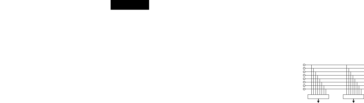
#4 INPUT ASSIGN (Input selectors)
• Select any source from eight inputs
(PHONO1/LINE1, LINE2, PHONO2/LINE3,
LINE4, PHONO3/LINE5, LINE6, LINE7, LINE8)
for each channel independently.
• You also can assign the same input to several
channels for creative mixing.
#5 GAIN (Line input level controls)
• Adjusts the level of the selected input.
• You can adjust each GAIN volume to indicate
0dB on source level meter.
#6 Source EQ controls
• Contour the frequency response of the selected
inputs.
At the center position, sound is flat.
HI and MID:
• Adjusts the high-tone and mid-tone sound –40
dB to +10 dB.
LOW:
• Adjusts the low-tone sound –40 dB to +6 dB.
NOTE:
Clipping may occur if adjustments are set to
harsh.
#7 CUE MASTER level meter
• Displays the output level following MASTER
LEVEL adjustment.
• Can switch between two display mode. See
below @4.
#8 Source level meters
• Displays the input level after adjusted with
GAIN #5 and EQ #6 controls.
NOTE:
If this meter indicates over +12 dB, inputted
sound may be clipped.
#9 EQ ON/OFF buttons
• When this button is lit EQ is on, otherwise EQ is
bypassed.
LINE1
LINE2
LINE3
LINE4
LINE5
LINE6
LINE7
LINE8
• • • • •
INPUT ASSIGN INPUT ASSIGN
CH1 CH4

7
ENGLISH
(2) Rear panel
$0 LINE2, 4, 6, 7, 8 input jacks
• These stereo pairs of unbalanced RCA jacks are
inputs for any line level device.
$1 PHONO1, 2, 3 / LINE1, 3, 5 input
jacks
• These stereo pairs of unbalanced RCA jacks are
inputs for a PHONO (RIAA) stage for magnetic
(MM) cartridges or a LINE stage suitable for any
device, such as a CD player.
$2 PHONO1, 2, 3 / LINE1, 3, 5 switches
• These switches change the input from PHONO
to a LINE level inputs.
• These switches set a LINE level inputs when
turntable is not connected.
$3 Phono ground screw (GND)
• This screws provide a place to connect the
ground wire from a turntable.
This terminal is exclusively for a turntable
grounding and not a safety earth ground.
$4 AUX MIC input jack
• Accepts a balanced microphone with 1/4” TRS
mono jacks.
• Pin layout: Tip=Hot Ring=Cold Sleeve=GND
$5 MAIN MIC input connector
• Neutrik combo jack.
• Accepts either a balanced microphone with an
XLR connector or an unbalanced microphone
with 1/4” TS mono jacks.
• Pin layout:
XLR: 1. GND 2. Hot 3. Cold
$6 Maintenance connector
NOTE:
This connector can be used only for firmware
updating. Do not connect device, or may cause
damage.
$7 LINE2, 4, 6, 8 FADER output jacks
• Connect these jacks to the FADER input jacks of
DN-S3000, DN-S5000, DN-D4000 and etc. using
the 3.5 mm stereo mini cord.
$8 SEND / RETURN jacks
• These 1/4” TS mono jacks allow external
processing of the program signal.
• When connect monaural type effect processor,
use Lch input and output.
$9 DIGITAL OUT (COAXIAL) jack
• This RCA jack provides a digital output data. The
signal is unaffected by the MASTER LEVEL
control.
• We recommend using a 75 Ω/ohm RCA cord for
best digital transfer. (available from any
audio/video retailer)
%0 REC OUT jacks
• This stereo pair of RCA jacks provide a line level
output. The signal is unaffected by the MASTER
LEVEL control.
%1 BOOTH OUT jacks
• This stereo pair of RCA jacks provide a
unbalanced line level output with independent
top panel BOOTH LEVEL control.
%2 MASTER OUT (UNBALANCED)
jacks
• This stereo pair of RCA jacks provide a
unbalanced line level output.
• Connect these jacks to the unbalanced analog
input jacks on an amplifier or console.
%3 LEVEL ATT
(Master out level attenuator)
• Use this to attenuate the MASTER output level.
(–∞~ 0 dB)
• Reference is 0 dB.
%4 MASTER OUT (BALANCED)
connectors
• These XLR type connectors provide a balanced
line level output.
• Connect these connectors to the balanced
analog input connectors on an amplifier or
console.
• Pin layout: 1. GND 2. Hot 3. Cold
• Applicable connector:
Cannon XLR-3-31 or equivalent.
NOTE:
Do not short-circuit the hot or cold pin with the
GND pin.
%5 MASTER MONO OUT ON/OFF
switch
• When this switch is on, mixed L and R signal is
outputted from the MASTER OUT (Both
BALANCED and UNBALANCED).
(3) Display
%6 Crossfader A assign indicators
• This indicator shows channels of assigned
channel to Crossfader A side.
%7 Preset mode indicators
%8 Sampler mode indicators
SAMP.:
• The Sampler sound is recorded.
LOOP:
• Playing Sampler in Loop mode.
REV.:
• Reverse Sampler playback.
%9 Character display
• This displays various operational information,
etc..
•[ 1 ] : CH-1 indicator
[ 2 ] : CH-2 indicator
[ 3 ] : CH-3 indicator
[ 4 ] : CH-4 indicator
The number of assigned input source is
displayed on the character display under these
indicator.
^0 Effect assign indicators
• Selected Effector source is indicated here.
^1 Crossfader B assign indicators
• This indicator shows channels of assigned
channel to Crossfader B side.
^2 Effector BPM display
• This display indicates the BPM of the assigned
source.
^3 BPM mode indicators
AUTO:
• This indicator is lit, when the BPM mode is
AUTO BPM.
• This indicator is flashed, when the AUTO BPM
is locked.
MANUAL:
• This indicator is lit, when the BPM mode is
manual BPM input. You can input desired BPM
by MODE PARAMETER knob.
^4 Cue button indicators
• Channels of CUE selected are indicated.
^5 Cue BPM display (Auto count)
• This display indicates the BPM of the selected
channel.
NOTE:
BPM will not be displayed, if 2 or more channels
are selected.
RLLRLR LR RL
L
R
R
LR
L
RL
RL
L R LR
DP-DJ151
Digital
Quartz
A
N
T
I
-
S
K
A
T
I
N
G
7
6
5
4
3
2
1
0
ON
SLOW
BRAKE
OFF
POWER
START
/STOP
45
0
1
2
3
4
33
78
+12
0
-12
PITCHKEY ADJUST
DP-DJ151
Digital
Quartz
A
N
T
I
-
S
K
A
T
I
N
G
7
6
5
4
3
2
1
0
ON
SLOW
BRAKE
OFF
POWER
START
/STOP
45
0
1
2
3
4
33
78
+12
0
-12
PITCHKEY ADJUST
DP-DJ151
Digital
Quartz
A
N
T
I
-
S
K
A
T
I
N
G
7
6
5
4
3
2
1
0
ON
SLOW
BRAKE
OFF
POWER
START
/STOP
45
0
1
2
3
4
33
78
+12
0
-12
PITCHKEY ADJUST
8
ENGLISH
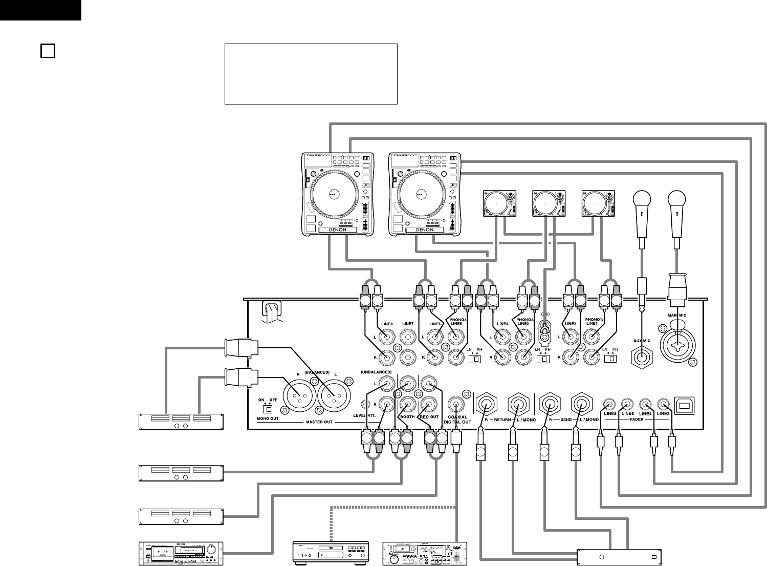
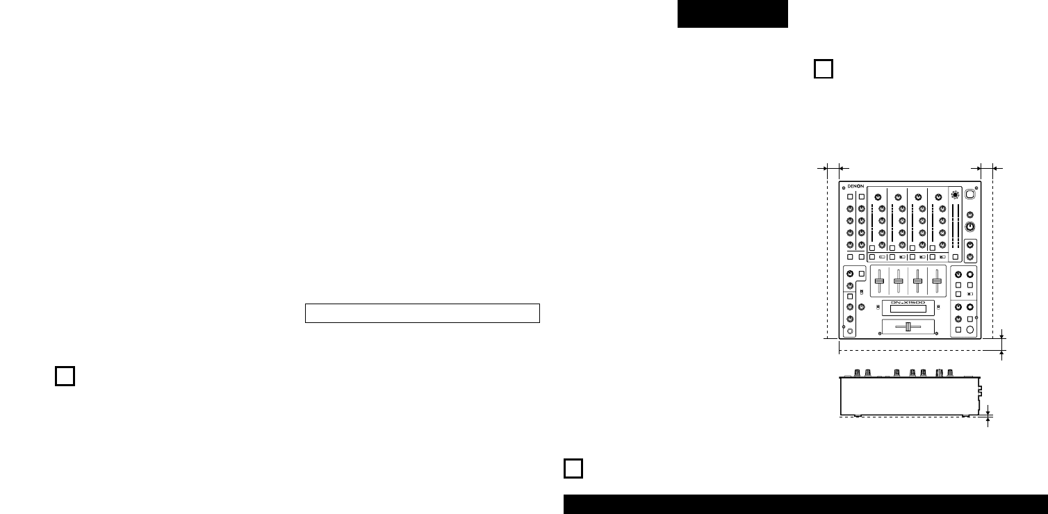
4CONNECTIONS
Refer to the connection diagram below.
1. Make certain AC power is off while making
connections.
2. Quality cables make a big difference in fidelity and
punch. Use high-quality, audio cables.
3. Do not use excessively long cables. Be sure plugs
and jacks are securely fastened. Loose connections
cause hum, noise, or intermittents that could
damage your speakers.
4. Connect all stereo input sources. Then connect any
effects into the stereo effect, if used. Connect your
microphone(s) and monitor headphones. Make sure
all faders are at “zero” and the unit is off. Take care
to connect only one cable at a time. pay attention to
L and R position of jacks, on both the DN-X1500 and
outboard gear.
5. Connect the stereo outputs to the power
amplifier(s) and/or tape deck(s) and/or MD
recorder(s) and/or CD recorder(s). Plug the DN-
X1500 into AC power outlet.
Tape deck
Turntable 2
Main unbalanced power amplifier
Main balanced power amplifier
Booth unbalanced power amplifier
MD recorderCD recorder or PC
CD player
1/4” TRS
mono jack
NOTE:
Always switch on your audio input sources such as
CD players first, then your mixer, and finally any
amplifiers. When turning off, always reverse this
operation by turning off amplifiers, then your mixer,
and then input units.
CD player
Turntable 1Turntable 3
3.5 mm stereo mini cord
3.5 mm stereo mini cord
1/4” TS mono jack
Effects processor
1/4” TS mono jack
1/4” TS mono jack
1/4” TS mono jack
XLR or 1/4” TRS
mono jack
Balanced microphones

9
ENGLISH
5SPECIFICATIONS
•Phono Inputs: 3 Stereo Unbalanced RCA jacks
Input Impedance 50 kΩ/kohms
Level –50 dBV (3 mV)
•Line Inputs: 5 Stereo Unbalanced RCA jacks
Input Impedance 50 kΩ/kohms
Level –14 dBV (200 mV)
•EQ Control (Line): 3 Bands
[Auto EQ]
Control Range & Frequency HI: –33 dB (15 kHz) to +10 dB (8 kHz)
MID: –40 dB (1 kHz) to +10 dB (1 kHz)
LOW: –40 dB (60 Hz) to +6 dB (60 Hz)
[Parametric EQ]
Control Range HI: –40 to +10 dB
MID: –40 to +10 dB
LOW: –40 to +6 dB
Frequency HI: 6 kHz to 20 kHz Default 13 kHz
MID: 200 Hz to 6 kHz Default 1 kHz
LOW: 20 Hz to 200 Hz Default 100 Hz
•Return Inputs: 2 Mono Unbalanced 1/4” TS jack
Input Impedance 50 kΩ/kohms
Level –14 dBV (200 mV)
•Mic Inputs: 2 Mono
Main Mic Active Balanced XLR and 1/4” TRS jack
(1: GND, 2: Hot, 3: Cold)
(Tip: Hot, Ring: Cold, Sleeve: GND)
Input Impedance 2 kΩ/kohms
Level –54 dBV (2 mV)
Frequency Response 20 Hz to 20 kHz (±3 dB)
S/N 65dB
Aux Mic Unbalanced 1/4” TS jack
(Tip: Hot, Sleeve: GND)
Input Impedance 1 kΩ/kohms
Level –60 dBV (1 mV)
Frequency Response 20 Hz to 20 kHz (±3 dB)
S/N 60dB
•EQ Control (Mic): 3 Bands
Control Range HI: –12 to +12 dB
MID: –12 to +12 dB
LOW: –12 to +12 dB
Frequency HI: 10 kHz
MID: 1 kHz
LOW: 100 Hz
•Master Output:
Balanced Stereo, Active Balanced XLR jacks
(1: GND, 2: Hot, 3: Cold)
Output Impedance 150 Ω/ohms
Level +4 dBu (1.23 V)
Frequency Response 20 Hz to 20 kHz (±2 dB)
THD+N Below 0.02 %
S/N 85 dB (Line) (When noise gate function set with presettings)
70 dB (Phono)
Cross Talk Over 70 dB
Unbalanced Stereo RCA jacks
Output Impedance 1 kΩ/kohms
Level 0 dBV (1 V)
Frequency Response 20 Hz to 20 kHz (±2 dB)
THD+N Below 0.02 %
S/N 85 dB (Line) (When noise gate function set with presettings)
70 dB (Phono)
Cross Talk Over 70 dB
•Rec Output: Stereo Unbalanced RCA jacks
Output Impedance 1 kΩ/kohms
Level –10 dBV (316 mV)
•Booth Output: Stereo Unbalanced RCA jacks
Output Impedance 1 kΩ/kohms
Level 0 dBV (1 V)
•Send Output: 2 mono Unbalanced 1/4” TS jacks
Output Impedance 1 kΩ/kohms
Level –14 dBV (200 mV)
•Headphone Output: Stereo
Output Impedance 100 Ω/ohms
Level 0 dBV (1 V)
•Digital Output: Coaxial IEC958 Type II
•Power Supply, Consumptions:
USA, Canada AC 120 V ± 10 %, 60 Hz 45 W
Europe, Asia, Oceania AC 230 V ± 10 %, 50 Hz 45 W
Unit Size 310 (W) x 90 (D) x 327 (H) mm
Mass 6.7 kg
✽Specifications and design are subject to change without notice for purpose of improvement.
10
ENGLISH
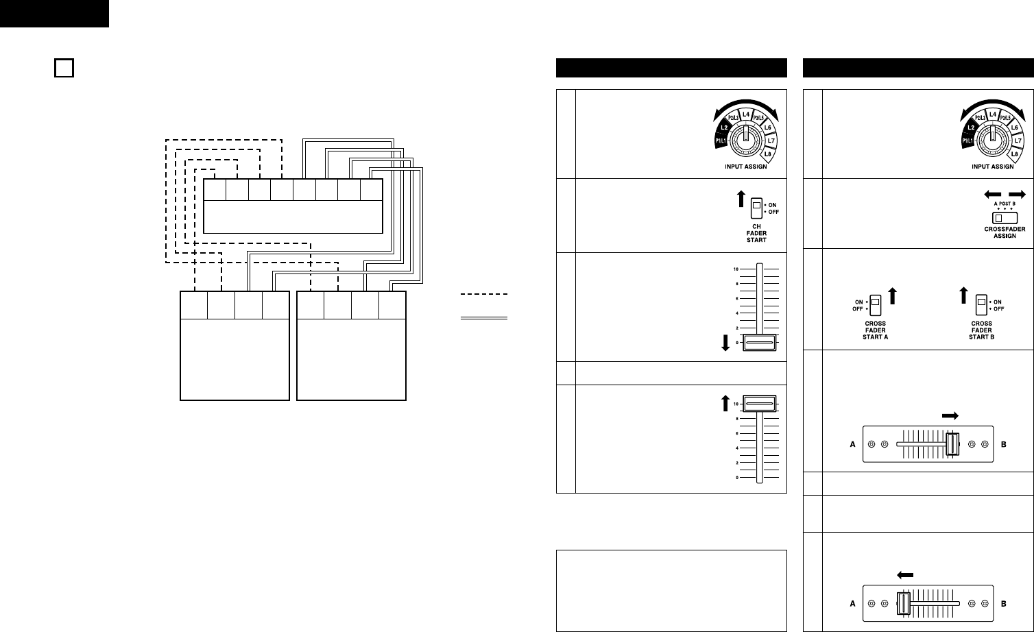
6FADER START
If the separately sold DN-S5000, DN-S3000, DN-D9000, DN-D4000 and etc. players are connected to LINE2, 4,
6 or 8, they can be started using the source input fader (Ch. Fader) or Crossfader, as long as the 3.5 mm stereo
mini cords have been connected.
LINE 2 LINE 4 LINE 6 LINE 8
FADER
LINE 2
FADER
LINE 4
FADER
LINE 6
FADER
LINE 8
DN-X1500
MAIN ALPHA
FADER
MAIN
FADER
ALPHA
DN-S5000
CD1
MAIN ALPHA
FADER
MAIN
FADER
ALPHA
DN-S5000
CD2
3.5 mm stereo mini cord
RCA cord
Channel Fader Start
Turn the INPUT ASSIGN
switch #4 to select the
desired source from LINE2,
4, 6 or 8.
1
2
Crossfader Start
NOTE:
• Channel Fader Start and Crossfader Start for the
same source will not operate simultaneously.
You must select from either one. If both CH
FADER START and CROSSFADER START A, B
switches are ON, priority will be the cross fader.
Turn on the CH FADER START
switch @6.
3
Move the source input fader
(Ch. Fader) !9 of CH-1, CH-2,
CH-3 or CH-4 control all the
way to the bottom.
4Set the standby mode on CD player.
5
When you want to start the
player, move up the source
input fader (Ch. Fader) !9 and
the CD player will begin
playing.
Turn the INPUT ASSIGN
switch #4 to select the
desired source from LINE2,
4, 6 or 8.
1
2
Using the CROSSFADER
ASSIGN switch !0, assign the
channel or Sampler source into A
or B of Crossfader.
3
Turn on the CROSSFADER START A, B
switches !7.
5Set the standby mode on CD player.
6Use the CROSSFADER CONTOUR control @0
to control the cross fader startup curve.
4
Slide the Crossfader !8 all the way in direction
opposite the source you want to start. (In the
following example, startup is done with the CD
player connected set to Assign A.)
7
When the Crossfader !8 is slid in the opposite
direction, CD player play will begin.
11
ENGLISH
7EFFECTOR
3
Select Effector mode (First selection)
Echo2, Filter2, Pan, Trans and Key% are set
in the preset mode.
• Turn the MODE PARAMETERS knob !2 to
select prefer effect mode.
• The effect mode changes and is displayed on
display by one click.
• After select prefer effect then push MODE
PARAMETERS knob !2 to complete the first
selection and go to the second selection.
None Delay Echo 1 (Echo 2)
Filter 1(Filter 2)Flanger
(Pan) (Trans) (Key %)
5
Time select
(Third selection for Delay, Echo1, Echo2,
Pan, Trans, Filter2 and Flanger)
•Beat mode:
Time parameter of effect is determined
based on countered BPM. BPM is countered
automatically in AUTO BPM mode or
manually inputted in MANUAL mode or
tapped in TAP mode.
Using the MODE PARAMETERS knob !2,
you can select time parameter. Selected time
parameter is used soon.
•Manual mode:
Time parameter of effect is inputted with
MODE PARAMETERS knob !2. Selected
time parameter is used soon.
• After select prefer parameter then push
MODE PARAMETERS knob !2 to return to
the first selection.
4
Beat effect and manual effect mode
(Second selection for Delay, Echo1, Echo2,
Pan, Trans, Filter2 and Flanger)
Manual effect mode is set in the preset
mode.
The default is “Manual OFF”. In this case,
skip to third selection (step 5).
• All effect modes excluded Key and Filter1
work with beat mode or manual mode. You
can choose beat or manual with MODE
PARAMETERS knob !2.
• After select prefer mode then push MODE
PARAMETERS knob !2 to complete the
second selection and go to the third
selection.
1Select the source of Effector
• Turn the ASSIGN switch !1 in the EFFECTS
part to select the desired source.
6
Key% select
(Second selection for Key%)
• Key is selected with MODE PARAMETERS
knob !2. Selected Key is used soon.
• After select prefer parameter then push
MODE PARAMETERS knob !2 to return to
the first selection.
7
WET/DRY control
• DN-X1500 can adjust the mixing ratio of
source sound and effected sound using
WET/DRY control !3.
• When turn to WET position Effector sound is
only outputted. Otherwise at DRY position
only source sound is outputted.
8
Effector On/Off
• Pushing ON/OFF button !4 to turn on and off
the Effector. When the Effector on, this
button lights.
First selection
Key% is selectable –100 % to
+100 %.
Flanger time is selectable 1/2, 1, 2, 4, 8, 16,
32 of BPM.
Second selection Third selection
Delay Beat Effect mode Delay time is selectable 1/4, 1/2, 3/4, 1/1,
2/1, 4/1, 8/1 of BPM.
Manual input mode Delay time can be set 1 to 3500 msec.
Echo 1 (Loop Echo)
• When the WET/DRY control
is turned clockwise, the
Echo sound is looped.
Pan
Preset functions
Trans
Preset functions
Filter 2 (Auto Filter)
Preset functions
Flanger
Key %
Preset functions
Beat Effect mode
Manual input mode
Beat Effect mode
Manual input mode
Beat Effect mode
Manual input mode
Beat Effect mode
Manual input mode
Beat Effect mode
Manual input mode
Echo time is selectable 1/4, 1/2, 3/4, 1/1,
2/1, 4/1, 8/1 of BPM.
Echo time can be set 1 to 3500 msec.
Panning time is selectable 1/4, 1/2, 3/4,
1/1, 2/1, 4/1, 8/1 of BPM.
Panning time can be set 10 to 16000 msec.
Trans time is selectable 1/4, 1/2, 3/4, 1/1,
2/1, 4/1, 8/1 of BPM.
Trans time can be set 10 to 16000 msec.
Filter time is selectable 1/2, 1, 2, 4, 8, 16,
32 of BPM.
Filter time can be set 10 to 16000 msec.
Flanger time can be set 10 to 16000 msec.
–
2
Set BPM (See page 6.)
• Using the TAP button !5 and the MODE
PARAMETERS knob !2, the BPM can be set
with either the AUTO BPM , TAP or MANUAL
input.
[About BPM]
• When using the auto BPM function, perform
the lock operation. When the BPM changes,
the effect sound changes.
• When the auto BPM cannot be measured,
use the TAP button and input the BPM.
• If you know the selection’s BPM, we
recommend inputting it in the manual mode.
Echo 2 (Normal Echo)
Preset functions
Beat Effect mode
Manual input mode
Echo time is selectable 1/4, 1/2, 3/4, 1/1,
2/1, 4/1, 8/1 of BPM.
Echo time can be set 1 to 3500 msec.
Filter 1 (Manual Filter)
• When the WET/DRY control
is turned, the Filter
frequency is moved.
Filter type is selectable
LowP.F. (Low-pass filter),
MidP.F. (Band-pass filter),
Hi P.F. (High-pass filter)
–
9
Effector Cue
• When the EFFECTS CUE button !6 is
pressed, you can check the effected sound
by headphone.
• The sound is unaffected by the EFFECTS
ON/OFF button !4.
12
ENGLISH
Sampler playback
8SAMPLER
1Select the source of Sampler
• Turn the ASSIGN switch yin the SAMPLER
part to select the desired source.
3
Setting B point / Stop recording
When the B button ois pushed during
recording, the B point is set.
• Recording continues for approximately 8
seconds without stopping after set B point.
• If the B point is not set, recording end point
set as B point automatically.
2
Record in Sampler
When the A button iis pushed, the sound of
the selected source is recorded to Sampler
memory up to 8 seconds.
• The A button iflashes after recording starts.
• When the recording is completed, B button
olights up.
5-1
Select Sampler play mode
You can select play mode for Sampler when
Sampler playback stop.
Loop (default):
Sampler playback continues with looping.
Single:
Sampler playback stops at B point.
Stutter:
Sampler is played while the A button iis
pressed and held down.
Loop + Reverse:
Reverse Sampler playback continues with
looping.
Single + Reverse:
Reverse Sampler stops at A point.
Stutter + Reverse:
Reverse Sampler is played while the A
button iis pressed and held down.
Exit B:
Sampler playback continues over B point
up to recording length.
6
Play Sampler sound
• Playback of the Sampler sound starts when
the A button iis pushed after recording has
completed.
• To stop the Sampler sound, push the MODE
knob u.
• When the CROSSFADER ASSIGN switch !0
in the SAMPLER part is set A or B, you can
perform the Sampler Fader Start by the
Crossfader !8. See page 10.
7
Moving Sampler B point
• When the B button ois pushed during
Sampler playback, the B point moves to the
point at which the button was pushed, and
Loop playback from point A starts.
4
Setting the Sampler sound level
The sound level (volume) can be set for
Sampler.
• To select “S_Level” turn the MODE knob u
and push.
• Turn the MODE knob uand select between
“–14 dB” and “+6 dB”.
9Clearing the Sampler data
• While pressing the MODE knob u, push the
A button ito clear the Sampler.
Sampler A/B Trim
1Select A-B Trim mode
• To select “A/BTrim” turn the MODE knob u
and push.
2
Select A point (in A-B Trim)
• Push the A button i.
• The A button iillumination flashes and Loop
playback starts.
5
Select B point (in A-B Trim)
• Select the A-B Trim mode and push the B
button o.
• The B button oillumination flashes.
3Trim A point
• Turn the MODE knob u. You can move the A
point.
4Save the A point
• Push the MODE knob uto save new the A
point.
6Trim B point
• Turn the MODE knob u. You can move the B
point.
9PFL (Pre Fader Level)
1. Press the SPLIT CUE button @4.
2. Press the CUE button !6 that you wish to monitor
1~ 4 (make sure your source is playing).
3. Turn the GAIN control #5 until the meters peak at
the 0 dB level.
4. Perform your mix using the Crossfader !8 or Ch.
Fader !9 at your desire.
NOTES:
• For proper operation, your channel levels should
always be set to or left on reference line 8.
• This adjustment can be made even if the Ch. Fader
is set to zero level.
Setting the Sampler pitch
The sound pitch can be set for Sampler.
• To select “S_Pitch” turn the MODE knob u
and push.
• Turn the MODE knob uand select between
“–100 %” and “+100 %”.
8
To select Loop/Reverse mode, turn the MODE
knob uthen push after recording and before
playing.
qPlay mode:
• To select “P_Mode” turn the MODE knob
uand push.
• Turn the MODE knob uand select
“Loop”, “Exit B”, “Single” or “Stutter”.
wPlay direction:
• To select “DirMode” turn the MODE knob
uand push.
• Turn the MODE knob uand select
“Forward” or “Reverse”.
5-2
10
Monitoring the Sampler data
(SAMPLER CUE)
• When the SAMPLER CUE button !6 is
pressed, you can check the Sampler data.
NOTE:
When the SAMPLER CUE button is lit, the
Sampler sound is not output into the
Crossfader or MASTER OUT.
7Save the B point
• Push the MODE knob uto save new the B
point.

13
ENGLISH
10 PRESET
1. Preset mode
qTurn the EFFECTS ASSIGN switch !1 to select “OFF”.
wThe preset mode is available when the TAP button !5 is pushed for more than 2 seconds.
eTurn the MODE PARAMETERS knob !2 to select the preset item.
rAfter selecting an item, push the MODE PARAMETERS knob !2 to select the preset data.
tTo change other preset items, repeat these steps.
yTo exit from preset mode, press the TAP button !5.
2. Preset items and data
The “*” mark next to the data indicates the default value.
(1) EQ Mode : EQ sound can select Auto or Parametric.
EQMode : Auto* / Para.
(2) High EQ Frequency :
When EQ mode is selected “Para.”, you can select high range frequency of 3 band EQ 6 kHz to
20 kHz.
HEQFreq : xxx Hz (13 kHz*)
(3) Middle EQ Frequency :
When EQ mode is selected “Para.”, you can select middle range frequency of 3 band EQ 200 Hz
to 6 kHz.
MEQFreq : xxx Hz (1 kHz*)
(4) Low EQ Frequency :
When EQ mode is selected “Para.”, you can select low range frequency of 3 band EQ 20 Hz to
200 Hz.
LEQFreq : xxx Hz (100 Hz*)
(5) High EQ Q :
When EQ mode is selected “Para.”, you can select high range Q of 3 band EQ.
HI_EQ_Q : Wide / Normal* / Narrow
(6) Middle EQ Q :
When EQ mode is selected “Para.”, you can select middle range Q of 3 band EQ.
MIDEQ_Q : Wide / Normal* / Narrow
(7) Low EQ Q :
When EQ mode is selected “Para.”, you can select low range Q of 3 band EQ.
LOWEQ_Q : Wide / Normal* / Narrow
(8) Headphone EQ :
Select EQ of headphone, High range boost, Low range boost or High + Low range boost.
H/P_EQ : Normal* / H_Boost / L_Boost / HLBoost
(9) Channel Fader Curve : Select the startup curve of channel fader.
CHCurve : Slow / Normal* / Sharp
(10) Crossfader Curve : Set the startup curve of Crossfader.
CRCurve : Normal / Sharp*
(11) Auto BPM : Auto BPM displays when the CUE button !6 is pressed.
AutoBPM : ON / OFF*
(12) Talk Over Level : You can select decreased level of the Talk Over function.
T.Over : –6 dB / –10 dB / –20 dB*
(13) Effector Manual mode ON/OFF :
Setting of whether or not to perform the Manual parameter mode of the internal Effector.
Manual Eff. : ON / OFF*
(14) Echo2 (Normal Echo) ON/OFF :
Setting of whether or not to perform the Echo2 (Normal Echo) of the internal Effector.
Echo 2 : ON / OFF*
(15) Filter2 (Auto Filter) ON/OFF :
Setting of whether or not to perform the Filter2 (Auto Filter) of the internal Effector.
Filter 2 : ON / OFF*
(16) Pan ON/OFF :
Setting of whether or not to perform the Pan of the internal Effector.
Pan : ON / OFF*
(17) Trans ON/OFF :
Setting of whether or not to perform the Trans of the internal Effector.
Trans : ON / OFF*
(18) Key% ON/OFF :
Setting of whether or not to perform the Key of the internal Effector.
Key% ↑ ↓ : ON / OFF*
(19) Noise Gate (CH) :
Setting of the function for attenuating the noise of the signals output from channels 1 to 4.
N.Gate CH : OFF* / Low / Hi
(20) Noise Gate (MIC) :
Setting of the function for attenuating the noise of the MIC signals.
N.Gate Mic : OFF* / ON
NOTES:
• The Noise Gate function is a function for attenuating the noise on the analog circuitry using internal digital
signal processing. Set it as desired.
• With the Noise Gate Function, the sound may seem distorted, for example when low level input signals
are input or when the level of the input signals is set low with the GAIN control.
(21) Display the microprocessor version. (“xxxx” is a number.)
Version : Sysxxxx / Panxxxx / Dspxxxx
(22) Preset Clear : Set all the preset data back to factory defaults. (“P.Init?”)
qTo clear the PRESET data, push the MODE PARAMETERS knob !2.
• “InitOK?” displays on the character display.
wPush the MODE PARAMETERS knob !2 again and start to clear the preset data.
• “Preset” and “Initial” are displayed on the character display while data clearing.
14
ESPAÑOL
1
FUNCIONES PRINCIPALES
1. Asignación de entradas de matriz
8 fuentes de entrada asignables libremente a cada
uno de los canales.
2. Penny & Giles Crossfader
Mezcla suave y fiable mejorada por el Crossfader
(dispositivo de atenuación cruzada) Penny & Giles.
3. Sampler
El sampler (dispositivo de muestreo) digital
integrado puede grabar hasta 8 segundos de
sonido con calidad CD. Puede realizar bucles
perfectos con este sampler o reproducirlo hacia
atrás (REVERSE). El nivel de altura de tono y de
salida del sampler pueden ajustarse de forma
independiente.
4. Reproductor interno de efectos
Puede llevar a cabo diferentes efectos de sonido.
(DELAY, ECHO, PAN, TRANS, FILTER, FLANGER,
KEY)
5. Contador automático de BPM, Bloqueo de
BPM, TAP y entrada manual de BPM
Además de un contador automático de BPM y de
la función de golpeteo, el equipo DN-X1500
también dispone de la función de bloqueo
temporal del contador automático de BMP y la
función de entrada manual de BPM.
6. Comienzo de Fader y Comienzo de Crossfader
El reproductor de CD puede ponerse en marcha y
detenerse simplemente aumentando o
disminuyendo el nivel del fader de Ch. o con el
fader de cruce de izquierda a derecha a o de
derecha a izquierda. (Esta función sólo puede
utilizarse cuando los reproductores de CD de
DENON DN-S3000, DN-S5000, DN-D6000 u otros
están conectados a la unidad DN-X1500.)
7. Salida digital
La unidad DN-X1500 le permite grabar
directamente en CD-R, MiniDisc o en un disco
duro mediante su salida digital coaxial exclusiva.
La salida digital mantiene una señal constante de
44,1 kHz.
8. Terminales SEND/RETURN mejorados
8 LINE, 3 PHONO, 2 sistemas de micrófono, 2
salidas MASTER, la salida BOOTH y la salida REC
son independientes. Los terminales de efectos
SEND/RETURN también están disponibles para un
procesador externo de efectos.
9. Ecualizador/Ganancia de 3 bandas
Los controles LOW, MID, HI y GAIN están
disponibles para todos los canales de entrada.
2INSTALACIÓN
Cuando la unidad DN-X1500 está instalada en una caja
o en una cabina de DJ, sepárela de la espuma
(esponja), las paredes o de cualquier otro equipo para
mejorar la disipación del calor.
3
NOMBRES Y FUNCIONES DE PARTES (Fate riferimento alla pagina 3.)
(1) Panel superior
qInterruptor de funcionamiento de
alimentación (POWER)
• La unidad se enciende cuando se pulsa el botón
de encendido desde la posición OFF (apagado
£) a la posición ON (encendido ¢).
• La unidad se apaga cuando el botón se pulsa
desde al posición ON (¢) a la posición OFF (£)
wControl MASTER BALANCE
• Ajusta el balance L/R de la salida MASTER.
eControl MASTER LEVEL
• Ajusta el nivel de las salidas MASTER.
rInterruptor BOOTH ASSIGN
• Selecciona la fuente de la salida BOOTH.
tControl BOOTH LEVEL
• Ajusta el nivel de la salida BOOTH.
yInterruptor SAMPLER ASSIGN
• Utilice esta función para seleccionar la fuente de
grabación del sampler.
uBotón SAMPLER MODE
• Utilice esta función para establecer el modo de
reproducción del sampler o para editar el
sampler.
• Pulse este botón durante la reproducción o la
grabación del sampler para detener la
reproducción o la grabación.
iBotón SAMPLER A
• Pulse este botón para iniciar la grabación o la
reproducción del sampler.
oBotón SAMPLER B
• Utilice esta función establecer el punto B del
sampler.
Min. 2 cm
– ÍNDICE –
zFUNCIONES PRINCIPALES..............................41
xINSTALACIÓN ..................................................41
c
NOMBRES Y FUNCIONES DE PARTES
...41 ~ 43
vCONEXIONES...................................................44
bESPECIFICACIONES ........................................45
nFADER START ..................................................46
mEFECTOS..........................................................47
,SAMPLER.........................................................48
.PFL (Nivel de pre-desvanecimiento).................48
⁄0 PRESET ............................................................49
2ACCESSORIOS
Compruebe que los siguientes elementos se
encuentran en la caja junto con la unidad
principal:
qInstrucciones de operación...............................1
2INTRODUCCIÓN
Gracias por haber adquirido el reproductor de DENON DN-X1500 DJ MIXER.
DENON se siente orgulloso de presentar este avanzado DJ MIXER para los aficionados y amantes de la música
como una prueba más de la búsqueda sin obligaciones de DENON de lo último en calidad de sonido. El
rendimiento de alta calidad y la fácil operación sin duda le proporcionarán muchas horas de deleite con una
escucha excepcional.
Min. 2 cm
10. Modelado del Crossfader
Esta función permite ajustar la “forma” de la
respuesta del Crossfader (mando deslizante de
cruce) desde una curva suave para conseguir
deslizamientos largos, hasta el tono abrupto
necesario para cortes de actuaciones de alta
calidad y efectos de rayado de vinilos.
11. Post micrófono
Esta opción pasará la señal Mic a las salidas
BOOTH, REC y a la señal de salida DIGITAL.
En el modo OFF, la señal Mic no pasará a través de
las salidas mencionadas anteriormente.
12. PFL (Nivel de pre-desvaneciemiento)
Esta función provee un medio para ajustar la
ganancia de nivel de entrada de cada canal para
evitar sobremodulación. Al realizar este ajuste por
adelantado asegurará una transición suave entre
los desvanecimientos cruzados o los
desvanecimientos de canal.
13. Funciones preseleccionadas
Es posible personalizar la máquina a sus
preferencias guardando sus ajustes favoritos en la
memoria interna. Para conocer los elementos que se
encuentran en las presets, consulte la página 49.
Min. 2 cm
Min. 3 mm
15
ESPAÑOL
!0 Interruptor CROSSFADER ASSIGN
A, B:
• La fuente del canal está asignada al punto A o al
B del crossfader.
POST:
• Seleccione si no asigna la fuente del canal en el
crossfader.
!1 Interruptor EFFECTS ASSIGN
• Utilice esta función seleccionar la fuente del
reproductor interno de efectos.
!2 Botón MODE PARAMETER
• Utilice esta función establecer el modo y los
parámetros de los efectos.
!3 Control EFFECTS WET/DRY
• Utilice esta función para ajustar la relación entre
el sonido original y los efectos.
!4 Botón EFFECTS ON/OFF
• Utilice esta función para cambiar entre ON y
OFF en la función del reproductor interno de
efectos.
!5 Botón TAP
•TAP:
Si pulsa este botón de forma repetida, de
desactivará el modo AUTO y comenzará la
medición de los Beats por minuto (BPM)
mediante tapping.
•LOCK:
Cuando se pulsa este botón mientras está
funcionando el contador automático BPM, los
datos medidos por el contador automático BPM
quedan bloqueados.
•AUTO:
Cuando se pulsa el botón TAP durante 1
segundo, se activa el modo AUTO BPM.
Los BPM obtenidos se muestran en el
visualizador BPM.
•INPUT BPM:
Cuando el botón TAP se mantiene pulsado
durante más de 2 segundos, el modo de entrada
BPM se establece y el valor BPM puede
introducirse directamente con el botón MODE
PARAMETERS !2. Cuando se vuelve a pulsar
este botón, se desactiva el modo de entrada
BPM.
!6 Botones CUE
• La pulsación de cualquier o todos los botones
CUE envía la Fuente respectiva a las secciones
de Auriculares y Señal de Indicación de Medidor.
La pulsación de múltiples botones posibilita la
derivación del sonido mezclado de las fuentes
seleccionadas.
!7 Interuptores CROSSFADER START
A, B
• Utilice esta opción para cambiar entre ON y OFF
en la función de inicio de crossfader.
!8 Crossfader
• Controla el nivel de salida relativo de las
Mezclas A y B sumadas. Cuando el fader está a
la izquierda, sólo se oirá la mezcla A por las
salidas. A medida que el fader se mueve hacia
la derecha, la Mezcla B aumenta y la mezcla A
disminuye. Cuando el fader está en el centro,
las Mezclas A y B son enviadas a las Salidas por
igual. Todo a la derecha es sólo la Mezcla B en
las Salidas.
!9 Fader de entrada de fuente
(Fader de Ch.)
• Controla el nivel de la entrada seleccionada.
@0 Control CROSSFADER CONTOUR
• Permite ajustar la “forma” de la respuesta del
Crossfader (mando deslizante de cruce) desde
una curva suave para conseguir deslizamientos
largos, hasta el tono abrupto necesario para
efectos de cortes de actuaciones de alta calidad
y efectos de rayado de vinilos.
@1 Toma de salida HEADPHONE
• Acepta conectores de auriculares estéreo de 1/4”.
@2 Control HEADPHONE LEVEL
• Ajusta el volumen del sonido en los auriculares.
@3 Control HEADPHONE PAN
•
Tiene dos propósitos. En el modo STEREO
cambia los niveles relativos de Señal de
Indicación y Programa (CUE MASTER) mezclados
en los dos audífonos. En el modo SPLIT CUE
(MONO) cambia el balance entre Señal de
Indicación Mono en el audífono izquierdo y el
Programa mono (MASTER) en el derecho.
@4 Botón SPLIT CUE
• En el modo STEREO, este botón alimenta el
STEREO-Programa (CUE MASTER) y Señal de
Indicación STEREO a los dos audífonos del
auricular, en el modo SPLIT CUE (MONO), el
circuito de Auriculares proporciona una Señal de
Indicación MONO al audífono izquierdo y un
Programa MONO (MASTER) al derecho.
• En el modo STEREO, el medidor indica el nivel
estéreo en las salidas Master LEFT y RIGHT.
En el modo SPLIT CUE (MONO), el nivel de
Señal de Indicación mono se indica en el
medidor Izquierdo y el nivel de Programa mono
(CUE MASTER) se indica en el medidor
derecho.
• En el modo SPLIT CUE (MONO), el botón se
ilumina.
@5 Control EFFECT LOOP WET/DRY
• Utilice esta función para ajustar la relación entre
el sonido original y los efectos.
@6 Interruptor CH FADER START
• Utilice esta función para cambiar entre ON y
OFF en la función de inicio de atenuación de
canal.
@7 Interruptor EFFECT LOOP ASSIGN
• Utilice esta función para seleccionar la fuente
del procesador externo.
@8 Botón EFFECT LOOP ON/OFF
• Dirige la señal asignada a través del procesador
externo acoplado a los conectores
SEND/RETURN de la parte trasera.
• Con el modo EFFECT en la posición ON, el
botón se ilumina. (cuando el procesador no está
conectado, el botón parpadeará una vez
activado).
@9 Botón TALK OVER ON/OFF
• Utilice esta función para cambiar entre ON y
OFF en la función de sonido superpuesto.
• Cuando el botón está iluminado, se atenúa el
nivel de las señales excepto la señal Mics.
• El nivel de atenuación de sonido superpuesto
puede ajustarse en el modo Preset.
NOTA:
Cuando se pulsa este botón, el volumen cambia
rápidamente.
#0 Botón MIC POST ON/OFF
• Pasa las señales Mic en la ruta de las señales
BOOTH, REC y salida digital.
#1 Controles de MIC EQ
• Modela la respuesta de frecuencia de la entrada
de Micrófono Principal de –12 dB a +12 dB.
En la posición central el sonido será plano.
#2 Controles de MIC LEVEL
• Ajusta el nivel de la señal Mic.
#3 Botones MIC ON/OFF
• Cuando el botón está iluminado, la señal Mic se
transfiere a la sección de salida; si no está
iluminado, la entrada Mic queda silenciada.
#4
INPUT-ASSIGN (Selectores de entrada)
• Seleccione cualquiera de las fuentes de las ocho
entradas (PHONO1/LINE1, LINE2,
PHONO2/LINE3, LINE4, PHONO3/LINE5,
LINE6, LINE7, LINE8) para cada uno de los
canales de forma independiente.
• También puede asignar la misma entrada a
varios canales para conseguir una mezcla
creativa.
#5
GAIN (Controles de nivel de entrada de línea)
• Ajusta el nivel de la entrada seleccionada.
• Puede ajustar cada uno de los volúmenes GAIN
para indicar 0dB en el medidor de nivel de
fuente.
#6 Controles de EQ de la fuente
• Modela la respuesta de frecuencia de las
entradas seleccionadas.
En la posición central el sonido será plano.
HI y MID:
• Ajuste el sonido de tono alto y de tono medio
entre –40 dB y +10 dB.
LOW:
• Ajusta el sonido de registros graves de –40 dB a
+6 dB.
NOTA:
Si el ajuste se realiza a muy agudo puede
producirse saturación.
#7 Medidor de nivel CUE MASTER
• Muestra el nivel de salida tras el ajuste MASTER
LEVEL.
• Puede conmutar entre dos modos de
visualización. Véase más adelante @4.
#8 Medidores de nivel de fuente
• Muestra el nivel de entrada una vez ajustado
con los controles GAIN #5 y EQ #6.
NOTA:
Si el medidor indica un nivel superior a +12 dB,
el sonido introducido puede cortarse.
#9 Botones EQ ON/OFF
• Cuando ese botón está iluminado, el control EQ
está activado; si no está iluminado, el control EQ
queda desactivado.
LINE1
LINE2
LINE3
LINE4
LINE5
LINE6
LINE7
LINE8
• • • • •
INPUT ASSIGN INPUT ASSIGN
CH1 CH4

16
ESPAÑOL
(2) Panel posterior
$0 Terminales de entrada LINE 2, 4, 6,
7, 8
• Estos pares de terminales RCA estéreo no
balanceados son entradas para cualquier
dispositivo de nivel de línea.
$1 Terminales de entrada PHONO 1, 2,
3 / LINE 1, 3, 5
• Estos pares de terminales RCA no balanceados
son entradas para una etapa Fono (RIAA)
cápsulas (MM) magnéticas o una etapa de Línea
adecuada para cualquier dispositivo, como un
reproductor de CD.
$2 Interruptores PHONO 1, 2, 3 / LINE
1, 3, 5
• Estos interruptores cambian la Entrada de Fono
a una entrada de nivel de Línea.
• Estos interruptores ajustan las entradas de nivel
de línea cuando un tocadiscos no está
conectado.
$3 Tornillo de Toma a Tierra de Fono
(GND)
• Estos tornillos permiten la conexión de un cable
de masa al plato.
Este terminal es exclusivo para la masa de un
plato y no para una conexión a tierra de
seguridad.
$4 Terminal de entrada AUX MIC
• Acepta un micrófono equilibrado con
conexiones modo TRS de 1/4”.
• Disposición de los contactos:
Punta=Caliente Anillo=Fria Funda=GND
$5 Conector de entrada MAIN MIC
• Terminal Neutrik combo.
• Acepta un micrófono equilibrado con un
conector XLR o un micrófono no equilibrado
con conexiones mono TS de 1/4”.
• Disposición de los contactos:
XLR: 1. GND 2. Caliente 3. Fría
$6 Conector de mantenimiento
NOTA:
Este conector sólo puede utilizarse para
actualizar el firmware. No conecte el dispositivo
o se podrían producir daños.
$7 Terminales de salida LINE2, 4, 6, 8
FADER
• Conecte estas clavijas a las tomas de entrada
FADER de las unidades DN-S3000, DN-S5000,
DN-D4000, etc., utilizando un minicable estéreo
de 3,5 mm.
$8 Terminales SEND / RETURN
• Estas conexiones mono TS de 1/4” permiten el
procesamiento externo de la señal del
programa.
• Cuando conecte el procesador de efectos de
tipo monoaural, utilice la entrada y la salida Lch.
$9 Terminale DIGITAL OUT (COAXIAL)
• Esta conexión RCA proporciona una salida de
datos digital. La señal no se ve afectada por el
control MASTER LEVEL.
• Se recomienda utilizar un cable RCA de
75Ω/ohmios para una transferencia digital
óptima. (disponible en comercios de
audio/vídeo).
%0 Terminales REC OUT
• Este par de terminales RCA estéreo proporciona
una salida de nivel de línea. La señal no resulta
afectada por el control MASTER LEVEL.
%1 Terminales BOOTH OUT
• Este par de conexiones RCA estéreo
proporciona una salida de nivel de línea no
equilibrada con el control BOOTH LEVEL de
panel superior independiente.
%2 Terminales MASTER OUT
(UNBALANCED)
• Este par de terminales RCA estéreo proporciona
una salida de nivel de línea no balanceada.
• Conecte estos terminales a los conectores de
entrada analógica no balanceada de un
amplificador o mesa de mezclas.
%3 LEVEL ATT
(Atenuador de nivel de salida Master)
• Utilice esta función para atenuar el nivel de
salida MASTER. (–∞~ 0 dB)
• El valor de referencia es 0 dB.
(3) Visualizador
%6 Indicadores de asignación del
Crossfader A
• Este indicador muestra los canales de canal
asignado para el lado del crossfader A.
%7 Indicadores de modos
preseleccionados
%8 Indicadores de modos de sampler
SAMP.:
• El sonido del sampler se graba.
LOOP:
• Reproducción del sampler en modo Loop.
REV.:
• Reproducción inversa del sampler.
%9 Visualizador de caracteres
• Esta función muestra diferente información
operacional, etc.
•[ 1 ] : CH-1 indicador
[ 2 ] : CH-2 indicador
[ 3 ] : CH-3 indicador
[ 4 ] : CH-4 indicador
El número de fuente de entrada asignada se
muestra en el visualizador de caracteres situado
debajo de este indicador.
^0
Indicadores de asignación de efectos
• La fuente del reproductor de efectos
seleccionado se indica aquí.
^1 Indicadores de asignación del
Crossfader B
• Este indicador muestra los canales de canal
asignado para el lado del crossfader B.
%4 Conectores MASTER OUT
(BALANCED)
• Estos conectores de tipo XLR proporcionan una
salida de nivel de línea balanceada.
• Conecte estos terminales a los conectores de
entrada analógica balanceada de un amplificador
o mesa de mezclas.
• Disposición de los contactos:
1. GND 2. Caliente 3. Fría
• Conector aplicable:
Cannon XLR-3-31 o equivalente.
NOTA:
No cortocircuite el pin caliente ni el frío con el
pin GND.
^2
Visualizador de BPM del
reproductor de efectos
• Este visualizador indica los BPM de la fuente
asignada.
^3 Indicadores de modos de BPM
AUTO:
• Este indicador se ilumina cuando el modo de
BPM es AUTO BPM.
• Este indicador parpadea cuando el modo AUTO
BPM está bloqueado.
MANUAL:
• Este indicador se ilumina cuando el modo de
BPM es entrada BPM manual. Puede introducir
los BPM deseados mediante el botón MODE
PARAMETER.
^4 Indicadores de botones de entrada
• Se indican los canales de CUE (entrada)
seleccionados.
^5 Visualizador de BPM de entrada
(contador automático)
• Este visualizador indica los BPM del canal
seleccionado.
NOTA:
Los BPM no se visualizarán si 2 o más canales
están seleccionados.
%5 Interruptor MASTER MONO OUT
ON/OFF
• Cuando este interruptor esté en la posición ON,
la señal mezclada L y R saldrá a través de
MASTER OUT (tanto en el modo BALANCED
como en el modo UNBALANCED).
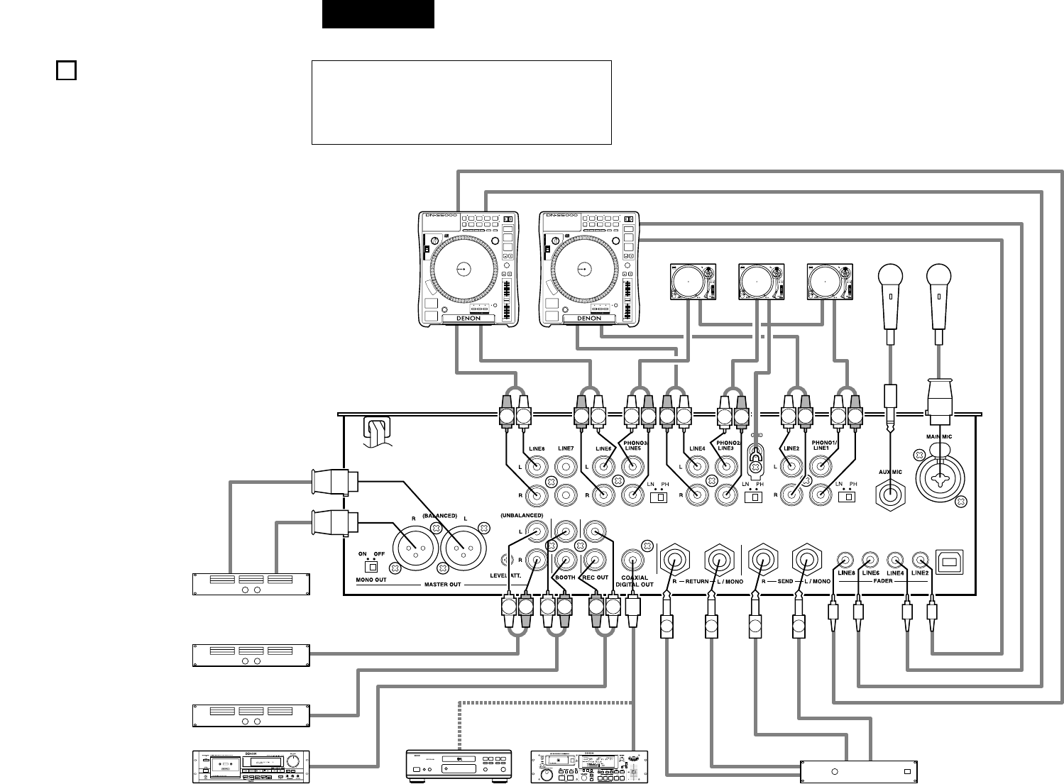
RLLRLR LR RL
L
R
R
LR
L
RL
RL
L R LR
DP-DJ151
Digital
Quartz
A
N
T
I
-
S
K
A
T
I
N
G
7
6
5
4
3
2
1
0
ON
SLOW
BRAKE
OFF
POWER
START
/STOP
45
0
1
2
3
4
33
78
+12
0
-12
PITCHKEY ADJUST
DP-DJ151
Digital
Quartz
A
N
T
I
-
S
K
A
T
I
N
G
7
6
5
4
3
2
1
0
ON
SLOW
BRAKE
OFF
POWER
START
/STOP
45
0
1
2
3
4
33
78
+12
0
-12
PITCHKEY ADJUST
DP-DJ151
Digital
Quartz
A
N
T
I
-
S
K
A
T
I
N
G
7
6
5
4
3
2
1
0
ON
SLOW
BRAKE
OFF
POWER
START
/STOP
45
0
1
2
3
4
33
78
+12
0
-12
PITCHKEY ADJUST
17
ESPAÑOL
4CONEXIONES
Remítase al Diagrama de Conexión que figura a
continuación.
1. Asegúrese de que la alimentación de c.a. está
desactivada al realizar las conexiones.
2. Los cables de calidad implican una gran diferencia
en cuanto a la fidelidad y a la pegada
conseguidas.Utilice cables de audio de alta calidad.
3. No utilice cables excesivamente largos. Asegúrese
de que los enchufes y los terminales queden
firmemente sujetos.Las conexiones flojas provocan
zumbidos, ruidos o intermitencias que podrían
dañar los altavoces.
4. Conecte todas las fuentes de entrada estéreo. A
continuación conecte la unidad de efectos en el
Efecto estéreo, si se utiliza alguno. Conecte el
micrófono(s) y los auriculares de
monitorización.Asegúrese de que todos los mandos
deslizantes se encuentran en la posición “cero” y
de que la unidad está apagada. Procure conectar
sólo un cable por vez. Preste atención a la posición
R y L de los conectores, tanto en el DN-X1500
como en el equipo externo.
5. Conecte las salidas estéreo al amplificador(es) y/o la
platina(s) y/o el grabador(es) de MD y/o los
grabadores de CD. Enchufe el DN-X1500 en la toma
de c.a. de la red eléctrica general.
Platina
Plato giradiscos 2
Amplificador de potencia no balanceado Principal
Amplificador de potencia balanceado Principal
Amplificador de potencia no balanceado Booth
Grabador de MDGrabador de CD o PC
Reproductor de CD
Terminal mono de
1/4” TRS
NOTA:
Encienda siempre primero las fuentes de entrada de audio tales
como reproductores CD, luego su mezclador, y finalmente
cualquier amplificador. Cuando lo apague, siempre realice la
operación inversa apagando los amplificadores, luego su
mezclador y luego las unidades de entrada.
Reproductor de CD
Plato giradiscos 1Plato giradiscos 3
Cable estéreo mini de 3,5 mm
Cable estéreo mini de 3,5 mm
Terminal mono de 1/4” TS
Procesador de efectos
Terminal mono de 1/4” TS
Terminal mono de 1/4” TS
Terminal mono de 1/4” TS
Terminal mono de
XLR o 1/4” TRS
Micrófonos balanceados

18
ESPAÑOL
5ESPECIFICACIONES
•Entradas Phono: 3 entradas estéreo Conexiones RCA no equilibradas
Impedancia de entrada 50 kΩ/kohmios
Nivel –50 dBV (3 mV)
•Entradas de línea: 5 entradas estéreo Conexiones RCA no equilibradas
Impedancia de entrada 50 kΩ/kohmios
Nivel –14 dBV (200 mV)
•Control de EQ (Línea): 3 bandas
[Auto EQ]
Intervalo de control HI: –33 dB (15 kHz) a +10 dB (8 kHz)
& Frecuencia MID: –40 dB (1 kHz) a +10 dB (1 kHz)
LOW: –40 dB (60 Hz) a +6 dB (60 Hz)
[Parametric EQ]
Intervalo de control HI: –40 a +10 dB
MID: –40 a +10 dB
LOW: –40 a +6 dB
Frecuencia HI: 6 kHz a 20 kHz Predeterminado 13 kHz
MID: 200 Hz a 6 kHz Predeterminado 1 kHz
LOW: 20 Hz a 200 Hz Predeterminado 100 Hz
•Entradas de retorno: 2 entradas Mono Conexión TS de 1/4” no equilibrada
Impedancia de entrada 50 kΩ/kohmios
Nivel –14 dBV (200 mV)
•Entradas Mic: 2 entradas Mono
Mic principal Equilibrio activo Conexión XLR y TRS de 1/4”
(1: GND, 2: Caliente, 3: Fría)
(Punta: Caliente, Anillo: Fría, Funda: GND)
Impedancia de entrada 2 kΩ/kohmios
Nivel –54 dBV (2 mV)
Respuesta de frecuencia 20 Hz a 20 kHz (±3 dB)
S/N 65 dB
Mic aux. Equilibrio Conexión TS de 1/4”
(Punta: Caliente, Funda: GND)
Impedancia de entrada 1 kΩ/kohmios
Level –60 dBV (1 mV)
Respuesta de frecuencia 20 Hz a 20 kHz (±3 dB)
S/N 60 dB
•Control de EQ (Mic): 3 bandas
Intervalo de control HI: –12 a +12 dB
MID: –12 a +12 dB
LOW: –12 a +12 dB
Frecuencia HI: 10 kHz
MID: 1 kHz
LOW: 100 Hz
•Salida Master:
Equilibrada Entradas estéreo, Conexiones XLR
Equilibrio activo (1: GND, 2: Caliente, 3: Fría)
Impedancia de salida 150 Ω/ohmios
Nivel +4 dBu (1,23 V)
Respuesta de frecuencia 20 Hz a 20 kHz (±2 dB)
THD+N Por debajo de 0,02 %
S/N 85 dB (Línea) (Cuando la función Noise Gate (Compuerta para el ruido) está
ajustada con parámetros preconfigurados)
70 dB (Fono)
Diafonía Más de 70 dB
No equilibrada Conexiones RCA estéreo
Impedancia de salida 1 kΩ/kohmios
Nivel 0 dBV (1 V)
Respuesta de frecuencia 20 Hz a 20 kHz (±2 dB)
THD+N Por debajo de 0,02 %
S/N 85 dB (Línea) (Cuando la función Noise Gate (Compuerta para el ruido) está
ajustada con parámetros preconfigurados)
70 dB (Fono)
Diafonía Más de 70 dB
•Salida Rec: Entradas estéreo Conexiones RCA no equilibradas
Impedancia de salida 1 kΩ/kohmios
Nivel –10 dBV (316 mV)
•Salida Booth: Entradas estéreo Conexiones RCA no equilibradas
Impedancia de salida 1 kΩ/kohmios
Nivel 0 dBV (1 V)
•Salida Send: 2 entradas Mono Conexiones TS de 1/4” no equilibrada
Impedancia de salida 1 kΩ/kohmios
Nivel –14 dBV (200 mV)
•Salida de auriculares: Estereofónica
Impedancia de salida 100 Ω/ohmios
Nivel 0 dBV (1 V)
•Salida Digital: Coaxial Tipo II IEC958
•Fuente de alimentación, consumos:
EE.UU. y Canadá c.a. 120 V ± 10 %, 60 Hz 45 W
Europa, Asia, Oceanía c.a. 230 V ± 10 %, 50 Hz 45 W
Tamaño de unidad 310 (Anch) x 90 (Prof) x 327 (Alt) mm
Peso 6,7 kg
✽Con el propósito de introducir mejoras, el diseño y las especificaciones del producto están
sujetos a cambios sin previo aviso.
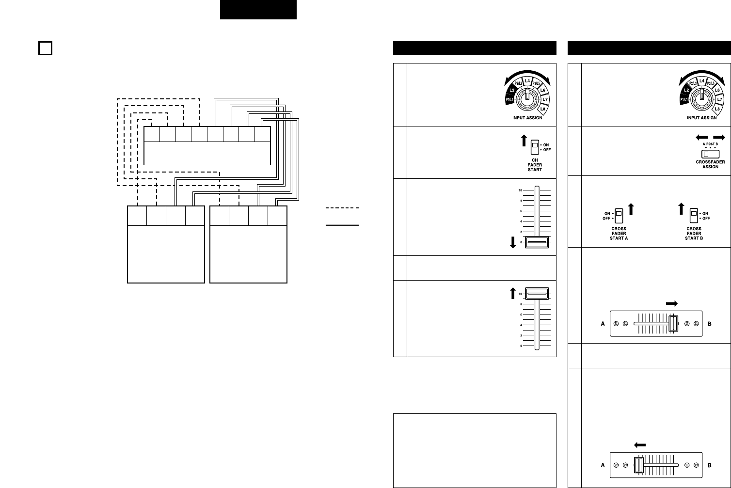
19
ESPAÑOL
6FADER START
Si los reproductores adquiridos independientemente DN-S5000, DN-S3000, DN-D9000, DN-D4000, etc., se
conectan a LINE2, 4, 6 u 8, pueden iniciarse utilizando el fader (fader de Ch.) o el Crossfader de entrada de fuente,
siempre que se hayan conectado los minicables estéreo de 3,5 mm.
LINE 2 LINE 4 LINE 6 LINE 8
FADER
LINE 2
FADER
LINE 4
FADER
LINE 6
FADER
LINE 8
DN-X1500
MAIN ALPHA
FADER
MAIN
FADER
ALPHA
DN-S5000
CD1
MAIN ALPHA
FADER
MAIN
FADER
ALPHA
DN-S5000
CD2
Cable estéreo mini
de 3,5 mm
Cable RCA
Comienzo de Fader de Canal
Accione el interruptor
INPUT ASSIGN #4 para
seleccionar la fuente
deseada desde LINE2, 4, 6
o 8.
1
2
Comienzo de Crossfader
NOTA:
• El comienzo de Fader de Canal y el Comienzo de
Fader de Cruce para la misma fuente no
funcionarán simultáneamente. Deberá
seleccionar uno de los dos. Si los interruptores
CH FADER START y CROSSFADER START A, B
están en la posición ON, la función que tendrá
prioridad será el crossfader.
Active el interruptor CH FADER
START @6.
3
Mueva el fader de entrada de
fuente (fader de Ch.) !9 del
control CH-1, CH-2, CH-3 o
CH-4 a fondo hacia abajo.
4Establezca el modo Standby en el reproductor
de CD.
5
Cuando desee iniciar el
reproductor, suba el fader de
entrada de fuente (fader de
Ch.) !9 y el reproductor de CD
comenzará a reproducir.
Accione el interruptor
INPUT ASSIGN #4 para
seleccionar la fuente
deseada desde LINE2, 4, 6
o 8.
1
2
Utilizando el interruptor
CROSSFADER ASSIGN !0,
asigne el canal o la fuente del
sampler en los puntos A o B del
crossfader.
3
Active los interruptores CROSSFADER START
A, B !7.
5Establezca el modo Standby en el reproductor
de CD.
6Use el control de CROSSFADER CONTOUR
@0 para controlar la curva de comienzo de
crossfader.
4
Deslice el Crossfader !8 a fondo en la dirección
opuesta a la fuente que desee dar comienzo.
(En el siguiente ejemplo, la inicialización se
completa con el reproductor de CD conectado
al punto de asignación A.)
7
Cuando el Crossfader !8 se desliza en el
sentido contrario, el reproductor de CD inicia su
funcionamiento.
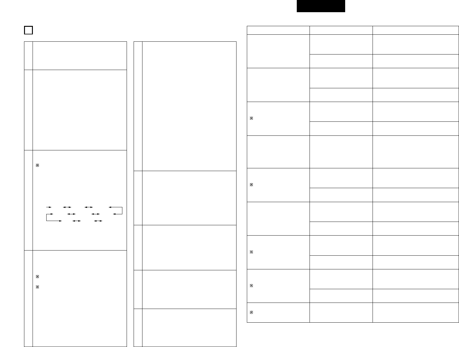
20
ESPAÑOL
7EFECTOS Primera selección
Puede seleccionarse Key%
entre –100 % y +100 %.
El tiempo de la pestañadora puede
seleccionarse 1/2, 1, 2, 4, 8, 16, 32 de
BPM.
Segunda selección Tercera selección
Delay Modo de efecto Beat El tiempo de retardo puede seleccionarse
1/4, 1/2, 3/4, 1/1, 2/1, 4/1 y 8/1 de BPM.
Modo de entrada Manual El tiempo de retraso puede ajustarse entre
1 a 3.500 mseg.
Echo 1 (Loop Echo)
• Cuando se gira el control
WET/DRY en el sentido de
las agujas del reloj, se
realiza un bucle con el
sonido Echo.
Pan
Funciones
preseleccionadas
Trans
Funciones
preseleccionadas
Filter 2 (Auto Filter)
Funciones
preseleccionadas
Flanger
Key %
Funciones
preseleccionadas
Modo de efecto Beat
Modo de entrada Manual
Modo de efecto Beat
Modo de entrada Manual
Modo de efecto Beat
Modo de entrada Manual
Modo de efecto Beat
Modo de entrada Manual
Modo de efecto Beat
Modo de entrada Manual
El tiempo de eco puede seleccionarse 1/4,
1/2, 3/4, 1/1, 2/1, 4/1, 8/1 de BPM.
El tiempo de eco puede ajustarse entre 1 a
3.500 mseg.
El tiempo de panorámica puede
seleccionarse 1/4, 1/2, 3/4, 1/1, 2/1, 4/1,
8/1 de BPM.
El tiempo de panorámica puede ajustarse
entre 10 a 16.000 mseg.
El tiempo de transferencia puede
seleccionarse 1/4, 1/2, 3/4, 1/1, 2/1, 4/1,
8/1 de BPM.
El tiempo de transferencia puede ajustarse
entre 10 a 16.000 mseg.
El tiempo de filtro puede seleccionarse 1/2,
1, 2, 4, 8, 16, 32 de BPM.
El tiempo de filtro puede ajustarse entre 10
a 16.000 mseg.
El tiempo de la pestañadora puede
ajustarse entre 10 a 16.000 mseg.
–
Echo 2 (Normal Echo)
Funciones
preseleccionadas
Modo de efecto Beat
Modo de entrada Manual
El tiempo de eco puede seleccionarse 1/4,
1/2, 3/4, 1/1, 2/1, 4/1, 8/1 de BPM.
El tiempo de eco puede ajustarse entre 1 a
3.500 mseg.
Filter 1 (Manual Filter)
• Cuando se gira el control
WET/DRY, cambia la
frecuencia de filtrado.
Puede seleccionarse el tipo de
filtro
LowP.F. (filtro de paso bajo),
MidP.F. (filtro de paso de banda),
Hi P.F. (filtro de paso alto)
–
3
Selección del modo del reproductor de
efectos (primera selección)
Los valores Echo2, Filter2, Pan, Trans y
Key% se establecen en el modo
preseleccionado.
• Accione el botón MODE PARAMETERS !2
para selccionar el modo de efectos preferido.
• El modo de efectos cambia y se visualiza
haciendo clic.
• Después de seleccionar el efecto deseado,
pulse el botón MODE PARAMETERS !2 para
completar la primera selección y pasar a la
segunda selección.
None Delay Echo 1 (Echo 2)
Filter 1(Filter 2)Flanger
(Pan) (Trans) (Key %)
5
Selección de tiempo
(Tercera selección para Delay, Echo1, Echo2,
Pan, Trans, Filter2 y Flanger)
•Modo Beat:
El parámetro de tiempo o efecto se
determinada basándose en los BMP
obtenidos. Los BPM se cuentan
automáticamente en el modo AUTO BPM, se
introducen manualmente en el modo
MANUAL o se insertan en el modo TAP.
Utilizando el botón MODE PARAMETERS !2,
puede seleccionar el parámetro de tiempo. El
parámetro de tiempo seleccionado se
utilizará en breve.
•Modo Manual:
El parámetro de tiempo o efecto se introduce
con el botón MODE PARAMETERS !2. El
parámetro de tiempo seleccionado se
utilizará en breve.
• Después de seleccionar el parámetro
deseado, pulse el botón MODE
PARAMETERS !2 para regresar a la primera
selección.
4
Modo de efecto de pulsación acústica y de
efecto manual (segunda selección para los
valores Delay, Echo1, Echo2, Pan, Trans,
Filter2 y Flanger)
El modo de efecto manual (Manual effect)
está establecido en el modo preseleccionado.
El valor predeterminado es “Manual OFF”. En
este caso, pase a la tercera selección (paso 5).
• Todos los modos de efectos a excepción de
los modos Key y Filter1 trabajar en modo de
pulsación acústica (Beat) o en modo Manual.
Puede elegir entre ambos modos con el
botón MODE PARAMETERS !2.
• Después de seleccionar el modo deseado,
pulse el botón MODE PARAMETERS !2 para
completar la segunda selección y pasar a la
tercera selección.
1
Seleccione la fuente del reproductor de efectos
• Accione el interruptor ASSIGN !1 en la
sección EFFECTS para seleccionar la fuente
deseada.
6
Selección del valor Key%
(Segunda selección para Key%)
• El valor Key se selecciona con el botón
MODE PARAMETERS !2. El valor Key
seleccionado se utilizará en breve.
• Después de seleccionar el parámetro
deseado, pulse el botón MODE
PARAMETERS !2 para regresar a la primera
selección.
7
Control WET/DRY
• La unidad DN-X1500 puede ajustar la relación
de mezcla del sonido fuente y de los efectos
utilizando el control WET/DRY !3.
• En la posición WET, sólo saldrá el sonido del
reproductor de efectos. En la posición DRY,
sólo saldrá el sonido fuente.
8
Activación/Desactivación del reproductor
de efectos
• Pulse el botón ON/OFF !4 tpara activar y
desactivar el reproductor de efectos. Cuando
el reproductor de efectos está activado, este
botón se ilumina.
2
BPM establecidos (Leer página 42.)
• Utilizando el botón TAP !5 y el botón MODE
PARAMETERS !2, los BPM pueden
establecerse con la entrada AUTO BPM , TAP
o MANUAL.
Acerca de BPM
• Cuando utilice la función automática de BPM,
lleve a cabo la función de bloqueo. Cuando el
BPM cambia, el ruido de efecto cambia.
•
Cuando el BPM automático no puede medirse,
utilice el botón TAP e introduzca el BPM.
• Si conoce el BPM de la selección, le
recomendamos que lo introduzca en el modo
manual.
9
Entrada efectos
• Cuando se pulsa el botón EFFECTS CUE !6,
se puede comprobar el sonido con efectos
mediante los auriculares.
• El sonido no se ve afectado por el botón
EFFECTS ON/OFF !4.
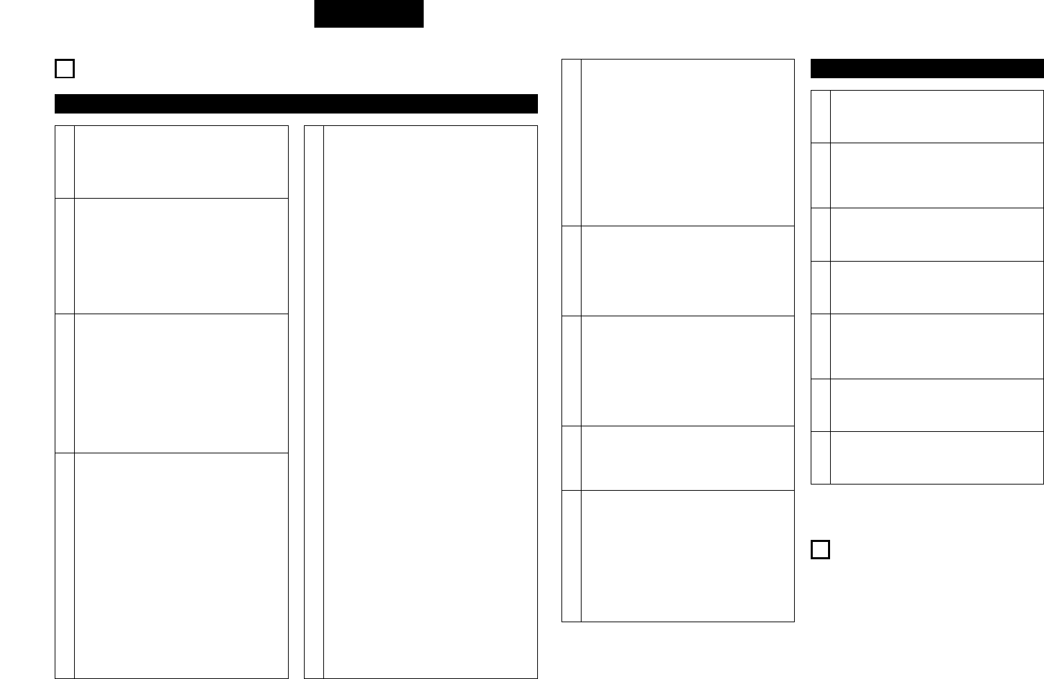
21
ESPAÑOL
Reproducción del sampler
8SAMPLER Sampler A/B Trim
1Seleccione el modo A-B trim
• Para seleccionar “A/BTrim”, gire y pulse el
botón MODE u.
2
Seleccione el punto A (A-B Trim)
• Pulse el botón A i.
• La iluminación del botón A iparpadeará y se
iniciará la reproducción del bucle.
5
Seleccione el punto B (in A-B Trim)
• Seleccione el modo A-B Trim y pulse el botón
B o.
• El botón B oparpadea.
3Recorte del punto A
• Gire el botón MODE u. Podrá desplazar el
punto A.
4Guarde el punto A
• Pulse el botón MODE upara guardar un
nuevo punto A.
6Recorte del punto B
• Gire el botón MODE u. Podrá desplazar el
punto B.
9
1. Pulse el botón del modo SPLIT CUE @4.
2. Pulse el botón CUE !6 que desee, para monitorear
1~4 (asegúrese de que su fuente se esté
reproduciendo).
3. Gire el control GAIN #5 hasta que el medidor
indique el nivel 0 dB.
4. Realice su mezcla utilizando el Crossfader !8 o
fader de Ch. !9 que desee.
NOTAS:
• Para un funcionamiento adecuado, sus niveles de
canal deben siempre ser ajustados o dejados en
línea de referencia 8.
• Este ajuste se puede realizar aún si el fader de Ch.
se ajusta al nivel cero.
7Guarde el punto B
• Pulse el botón MODE upara guardar un
nuevo punto B.
7
Mover el punto del Sampler B
• Cuando pulse el botón B odurante la
reproducción del sampler, el punto B se
moverá hasta el punto en el cual se pulso el
botón y reproducirá el bucle desde el punto
A.
9Borrar los datos del Sampler
• Pulse el botón MODE u mientras pulsa
también el botón A ipara borrar el sampler.
Ajuste de la altura tonal del sampler
La altura tonal del sonido puede ajustarse para
el sampler.
• Para seleccionar “S_Pitch”, gire y pulse el
botón MODE u.
• Gire el botón MODE uy seleccione entre
“–100 %” y “+100 %”.
8
10
Seguimiento de los datos del sampler
(SAMPLER CUE)
• Cuando se pulsa el botón SAMPLER CUE !6,
puede comprobar los datos del sampler.
NOTA:
Cuando se ilumina el botón SAMPLER CUE,
el sonido del sampler no sale a través del
Crossfader ni de la salida MASTER OUT.
5
Selección del modo de reproducción del
sampler
Puede seleccionar el modo de reproducción
para el sampler cuando se detenga la
reproducción del sampler.
Loop (predeterminado):
La reproducción del Sampler continúa en
modo bucle.
Single:
La reproducción del sampler se detiene
en el punto B.
Stutter:
El sampler se reproduce mientras el botón
A i se mantiene pulsado.
Loop + Reverse:
La reproducción inversa del sampler
continúa con blucles.
Single + Reverse:
La reproducción inversa del sampler se
detiene en el punto A.
Stutter + Reverse:
La reproducción inversa del sampler están
en marcha mientras se mantenga pulsado
el botón A i.
Exit B:
La reproducción del sampler continúa
sobre el punto B hasta alcanzar la longitud
de grabación.
Para seleccionar el modo Loop/Reverse, gire el
botón MODE uy púlselo después de la
grabación y antes de la reproducción.
qModo Play:
• Para seleccionar “P_Mode”, gire y pulse
el botón MODE u.
• Gire el botón MODE uy seleccione
“Loop”, “Exit B”, “Single” o “Stutter”.
wSentido de la reproducción:
• Para seleccionar “DirMde”, gire y pulse el
botón MODE u.
• Gire el botón MODE uy seleccione
“Forward” o “Reverse”.
6
Reproducir sonido de Sampler
• La reproducción del sonido del sampler se
inicia cuando se pulsa el botón A iuna vez
finalizada la grabación.
• Para detener el sonido del Sampler, pulse el
botón MODE u.
• Cuando el interruptor CROSSFADER ASSIGN
!0 de la sección SAMPLER se ajusta en los
puntos A o B, puede iniciar el modo Sampler
Fader Start en el Crossfader !8. Véase la
página 46.
1
Selección de la fuente del sampler
• Accione el interruptor ASSIGN yen la
sección SAMPLER para seleccionar la fuente
deseada.
3
Establecer punto B / Detener la grabación
Cuando se pulsa el botón B odurante la
grabación, el punto B queda establecido.
• La grabación continúa durante
aproximadamente 8 segundos sin pausa
después de establecer el punto B.
• Si el punto B no esta establecido, el punto
final de grabación quedará fijado de forma
automática en el punto B.
2
Grabar en Sampler
Cuando se pulsa el botón A i, se graban hasta
8 segundos del sonido de la fuente
seleccionada en la memoria del sampler.
• El botón A iparpadea una vez iniciada la
grabación.
• Una vez finalizada la grabación, el botón B o
se ilumina.
4
Cómo ajustar el nivel de sonido del sampler
Puede ajustarse el nivel de sonido (volumen)
para el sampler.
• Para seleccionar “S_Level”, gire y pulse el
botón MODE u.
• Gire el botón MODE uy seleccione entre
“–14 dB” y “+6 dB”.
PFL (Nivel de pre-
desvanecimiento)

22
ESPAÑOL
10 PRESET
1. Modo Preset
qAccione el interruptor EFFECTS ASSIGN !1 tpara seleccionar “OFF”.
wEl modo preseleccionado está disponible cuando el botón TAP !5 se pulsa durante más de 2 segundos.
eGire el botón MODE PARAMETERS !2 para seleccionar el elemento preestablecido.
rDespués de seleccionar el elemento, pulse el botón MODE PARAMETERS !2 para seleccionar los datos
preset.
tPara cambiar los datos Preset, repita los siguientes pasos.
yPara salir del modo preseleccionado, pulse el botón TAP !5.
2. lementos preset y datos
El símbolo “*” junto a los datos indica el valor por defecto.
(1) Modo EQ: El sonido EQ puede seleccionar los valores Auto o Parametric.
EQMode : Auto* / Para.
(2) Frecuencia EQ alta:
Cuando el modo EQ seleccionado es “Para.”, puede seleccionar una frecuencia de intervalo alta
de EQ de 3 bandas entre 6 kHz y 20 kHz.
HEQFreq : xxx Hz (13 kHz*)
(3) Frecuencia EQ media:
Cuando el modo EQ seleccionado es “Para.”, puede seleccionar una frecuencia de intervalo media
de EQ de 3 bandas entre 200 Hz y 6 kHz.
MEQFreq : xxx Hz (1 kHz*)
(4) Frecuencia EQ baja:
Cuando el modo EQ seleccionado es “Para.”, puede seleccionar una frecuencia de intervalo baja
de EQ de 3 bandas entre 20 Hz y 200 Hz.
LEQFreq : xxx Hz (100 Hz*)
(5) EQ Q alto:
Cuando el modo EQ seleccionado es “Para.”, puede seleccionar un valor Q de intervalo alto de
EQ de 3 bandas.
HI_EQ_Q : Wide / Normal* / Narrow
(6) EQ Q medio:
Cuando el modo EQ seleccionado es “Para.”, puede seleccionar un valor Q de intervalo medio de
EQ de 3 bandas.
MIDEQ_Q : Wide / Normal* / Narrow
(7) EQ Q bajo:
Cuando el modo EQ seleccionado es “Para.”, puede seleccionar un valor Q de intervalo bajo de
EQ de 3 bandas.
LOWEQ_Q : Wide / Normal* / Narrow
(8) EQ auriculares:
Seleccione el EQ para auriculares, aumento de intervalo alto, aumento de intervalo bajo o aumento
de intervalo alto-bajo.
H/P_EQ : Normal* / H_Boost / L_Boost / HLBoost
(9) Curva del fader de canal: Seleccione la curva de inicio del fader de canal.
CHCurve : Slow / Normal* / Sharp
(10) Curva del crossfader: Establece la curva de inicio del crossfader.
CRCurve : Normal / Sharp*
(11) Auto BPM: El modo Auto BPM se visualiza cuando se pulsa el botón CUE !6.
AutoBPM : ON / OFF*
(12) Nivel de sonido superpuesto: Puede seleccionar un nivel reducido de la función de sonido superpuesto
(Talk Over).
T.Over : –6 dB / –10 dB / –20 dB*
(13) Posición ON/OFF del modo manual del reproductor de efectos:
Ajusta si utilizar o no el modo de parámetro manual del reproductor interno de efectos.
Manual Eff. : ON / OFF*
(14) Posición ON/OFF de Echo2 (Normal Echo):
Ajusta si utilizar o no el modo Echo2 (Normal Echo) del reproductor interno de efectos.
Echo 2 : ON / OFF*
(15) Filter2 (Auto Filter) ON/OFF :
Ajusta si utilizar o no el modo Filter2 (Auto Filter) del reproductor interno de efectos.
Filter 2 : ON / OFF*
(16) Pan ON/OFF :
Ajusta si utilizar o no el modo Pan del reproductor interno de efectos.
Pan : ON / OFF*
(17) Trans ON/OFF :
Ajusta si utilizar o no el modo Trans del reproductor interno de efectos.
Trans : ON / OFF*
(18) Key% ON/OFF :
Ajusta si utilizar o no el modo Key del reproductor interno de efectos.
Key% ↑ ↓ : ON / OFF*
(19) Noise Gate (CH) :
Configuración de la función para atenuar el ruido de la emisión de señales de los canales 1 a 4.
N.Gate CH : OFF* / Low / Hi
(20) Noise Gate (MIC) :
Configuración de la función para atenuar el ruido de las señales del MIC.
N.Gate Mic : OFF* / ON
NOTAS:
• La función Noise Gate sirve para atenuar el ruido del circuito análogo mediante un proceso de señal digital
interna. Ajústelo como desee.
• Con la función Noise Gate, el sonido puede parecer distorsionado, por ejemplo cuando se reciben señales
de bajo nivel o cuando el nivel de las señales de entrada está bajo con el mando GAIN.
(21) Muestra la versión de microprocesador. (“xxxx” es un número)
Version : Sysxxxx / Panxxxx / Dspxxxx
(22) Borrar preajuste :
Restablecer todos los datos preestablecidos a la configuración de fábrica. (“P.Init?”)
qPara borrar los datos PRESET, pulse los botón MODE PARAMETERS !2.
• “InitOK?” aparece en el visualizador de caracteres.
wPulse el botón MODE PARAMETERS !2 de nuevo e inicie para borrar los datos establecidos
previamente.
• “Preset” e “Initial” aparecen en el visualizador de caracteres mientras se borran los datos.

16-11, YUSHIMA 3-CHOME, BUNKYO-KU, TOKYO 113-0034, JAPAN
Telephone: (03) 3837-5321 Printed in Japan 511 4143 007
