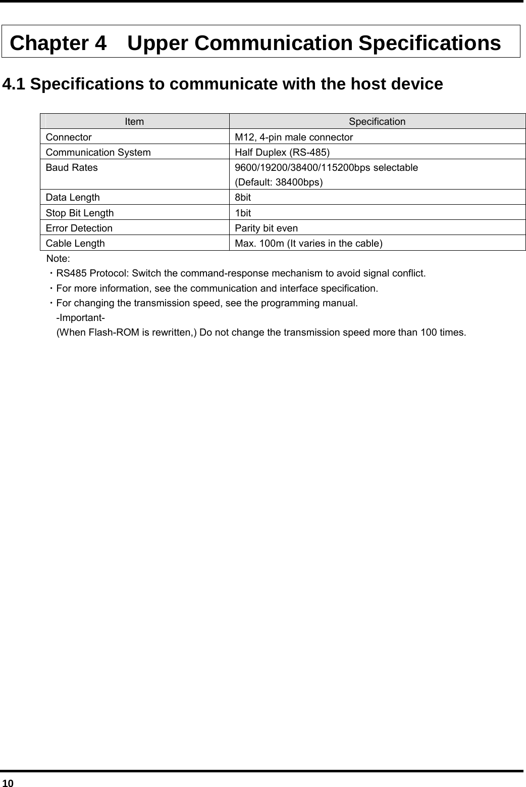
Denso Wave orporated AN22R01 High Frequency 13.56MHz Transceiver User Manual 1 1 1732 cover v0 90
Denso Wave Incorporated High Frequency 13.56MHz Transceiver 1 1 1732 cover v0 90
UserManual.wiki
>
Denso Wave orporated
>
AN22R01 User Manual
Users manual_v0.92
Navigation menu
Upload a User Manual
Namespaces
Wiki Guide
HTML
PDF
Info
Views
User Manual
Discussion / Help
Navigation
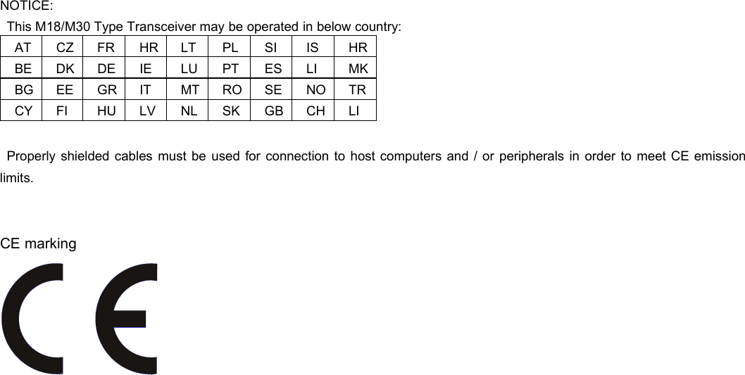
![For European Union [EN] English Hereby, DENSO WAVE INCORPORATED declares that this equipment (M18/M30 Type Transceiver) is in compliance with the essential requirements and other relevant provisions of Directive 1999/5/EC. [BG] Bulgarian , DENSO WAVE INCORPORATED, , M18/M30 Type Transceiver 1999/5/EC. [HR] Croatian Ovim DENSO WAVE INCORPORATED, izjavljuje da je M18/M30 Type Transceiver u sklau s bitnim zahtjevima i drugim relevantnim odredbama Direktive 1999/5/EC i Pravilnika o RiTT opremi (NN25/2012). [CS] Czech DENSO WAVE INCORPORATED tímto prohlašuje, že M18/M30 Type Transceiver spluje základní požadavky a všechna píslušná ustanoveni Smrnice 1999/5/ES. [DA] Danish Undertegnede DENSO WAVE INCORPORATED erklærer herved, at følgende udstyr M18/M30 Type Transceiver overholder de væsentlige krav og øvrige relevante krav i direktiv 1999/5/EF. [DE] German Hiermit erklärt DENSO WAVE INCORPORATED, dass sich das Gerät M18/M30 Type Transceiver in Übereinstimmung mit den grundlegenden Anforderungen und den übrigen einschlägigen Bestimmungen der Richtlinie 1999/5/EG befindet. [ET] Estonian Käesolevaga kinnitab DENSO WAVE INCORPORATED seadme M18/M30 Type Transceiver vastavust direktiivi 1999/5/EÜ põhinõuetele ja nimetatud direktiivist tulenevatele teistele asjakohastele sätetele. [EL] Greek DENSO WAVE INCORPORATED M18/M30 Type Transceiver 1999/5/ [ES] Spanish Por la presente, DENSO WAVE INCORPORATED, declara que este M18/M30 Type Transceiver cumple con los requisitos esenciales y otras exigencias relevantes de la Directiva 1999/5/EC. [FR] French Par la présente, DENSO WAVE INCORPORATED déclare que l’appareil M18/M30 Type Transceiver est conforme aux exigencies essentielles et aux autres dispositions pertinentes de la directive 1999/5/CE. [IT] Italian Con la presente DENSO WAVE INCORPORATED dichiara che questo M18/M30 Type Transceiver è conforme ai requisiti essenziali ed alle altre disposizioni pertinenti stabilite dalla direttiva 1999/5/CE. [LV] Latvian Ar šo DENSO WAVE INCORPORATED deklar, ka M18/M30 Type Transceiver atbilst Direktvas 1999/5/EK btiskajm prasbm un citiem ar to saisttajiem noteikumiem. [LT] Lithuanian Šiuo DENSO WAVE INCORPORATED deklaruoja, kad šis M18/M30 Type Transceiver atitinka esminius reikalavimus ir kitas 1999/5/EB Direktyvos nuostatas [HU] Hungarian A DENSO WAVE INCORPORATED ezzennel kijelenti, hogy a HIGH FREQUENCY 13.56MHz TRANSCEIVER típusú beren-dezés teljesíti az alapvet követelményeket és más 1999/5/EK irányelvben meghatározott vonatkozó rendelkezéseket. [NL] Dutch Hierbij verklaart DENSO WAVE INCORPORATED dat het toestel l HIGH FREQUENCY 13.56MHz TRANSCEIVER in overeenstemming is met de essentiële eisen en de andere relevante bepalin-gen van richtlijn 1999/5/EG. [PL] Polish Niniejszym DENSO WAVE INCORPORATED deklaruje e HIGH FREQUENCY 13.56MHz TRANSCEIVER jest zgodny z zasadniczymi wymaganiami iinnymi waciwymi postanowieniami Dyrektywy 1999/5/EC. [PT] Portuguese Eu, DENSO WAVE INCORPORATED, declaro que o HIGH FREQUENCY 13.56MHz TRANSCEIVER cumpre os requisitos essenciais e outras provisões relevantes da Directiva 1999/5/EC. [RO] Romanian Prin prezenta, DENSO WAVE INCORPORATED, declar c aparatul HIGH FREQUENCY 13.56MHz TRANSCEIVER este în conformitate cu cerinele eseniale i cu alte prevederi pertinente ale Directivei 1999/5/CE. [SK] Slovak DENSO WAVE INCORPORATED týmto vyhlasuje, že HIGH FREQUENCY 13.56MHz TRANSCEIVER spa základné požiadavky a všetky príslušné ustanovenia Smernice 1999/5/ES. [SL] Slovenian DENSO WAVE INCORPORATED izjavlja, da je ta HIGH FREQUENCY 13.56MHz TRANSCEIVER v skladu z bistvenimi zahtevami in drugimi relevantnimi doloili direktive 1999/5/ES. [FI] Finish DENSO WAVE INCORPORATED vakuuttaa täten että HIGH FREQUENCY 13.56MHz TRANSCEIVER tyyppinen laite on direktiivin 1999/5/EY oleellisten vaatimusten ja sitä koskevien direktiivin muiden ehtojen mukainen. [SV] Swedish Denna utrustning är i överensstämmelse med de väsentliga kraven och andra relevanta bestämmelser i direktiv 1999/5/EC. Declaration of Conformity (For European Union)](https://usermanual.wiki/Denso-Wave-orporated/AN22R01/User-Guide-1746657-Page-3.png)
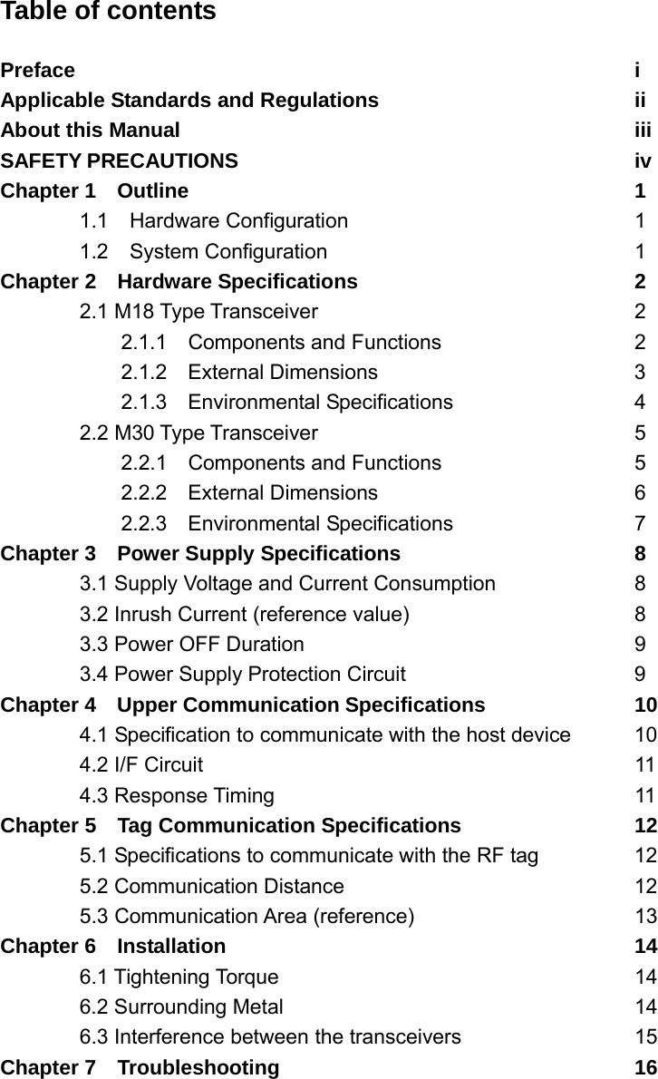
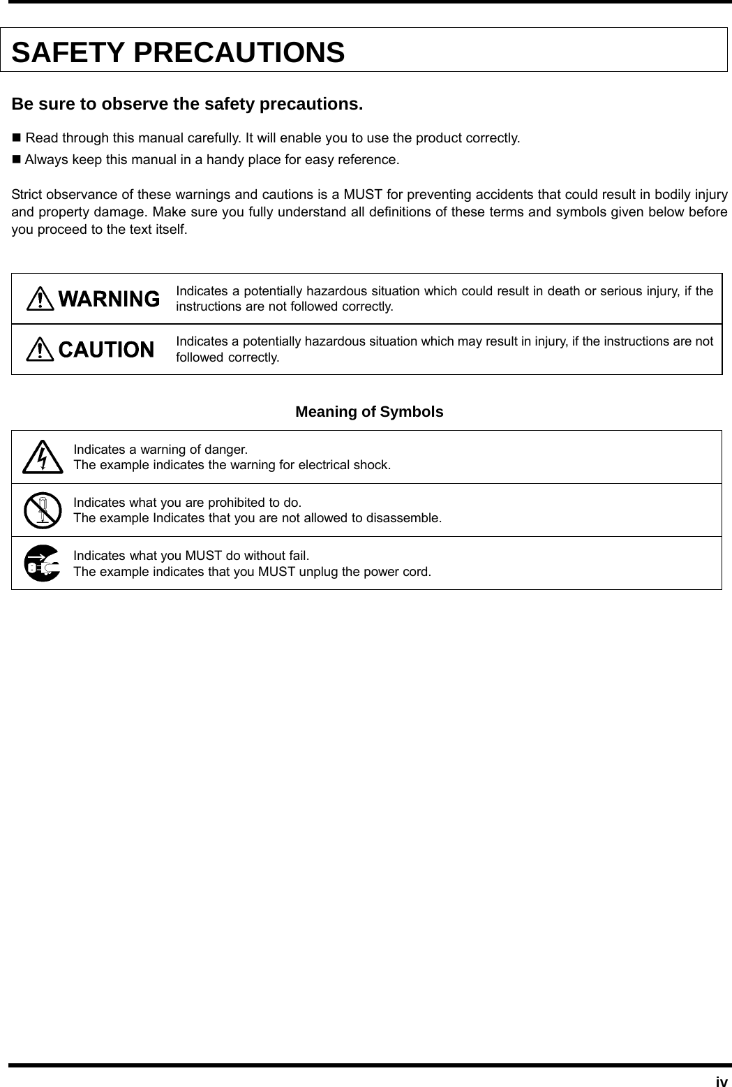
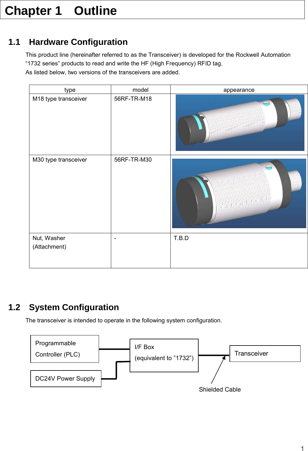
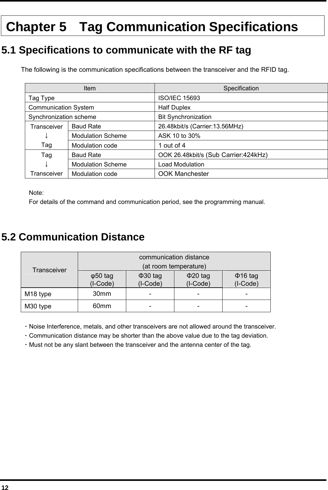
![13 5.3 Communication Area (reference) M18 Type * 50 tag M30 Type * 50 tag * It isn't mentioned in the Side-Band-Area. -100-80-60-40-200204060801000 20 40 60 80 100 120 140 160 180-100-80-60-40-20020406080100-100-80 -60 -40 -20 0 20 40 60 80 100distance 60mm [mm][mm]-60-50-40-30-20-1001020304050600 102030405060708090100110-60-50-40-30-20-100102030405060-60 -50 -40 -30 -20 -10 0 10 20 30 40 50 60distance 40mm[mm][mm] T.B.D T.B.D](https://usermanual.wiki/Denso-Wave-orporated/AN22R01/User-Guide-1746657-Page-25.png)