Denso Wave orporated AN22R01 High Frequency 13.56MHz Transceiver User Manual 1 1 1732 cover v0 90
Denso Wave Incorporated High Frequency 13.56MHz Transceiver 1 1 1732 cover v0 90
Users manual_v0.92

M18 / M30 Cylindrical type transceiver
for 1732 series
User’s Manual

NOTICE:
This equipment has been tested and found to comply with the limits for a Class A digital device, pursuant to
part 15 of the FCC Rules. These limits are designed to provide reasonable protection against harmful interference
when the equipment is operated in a commercial environment. This equipment generates, uses, and can radiate radio
frequency energy and, if not installed and used in accordance with the instruction manual, may cause harmful
interference to radio communications. Operation of this equipment in a residential area is likely to cause harmful
interference in which case the user will be required to correct the interference at his own expense.
Properly shielded and grounded cables must be used for connection to host computers and / or peripherals in order to meet FCC
emission limits.
FCC WARNING:
Changes or modifications not expressly approved by the party responsible for compliance could void the user’s authority to
operate the equipment.
FCC CAUTION:
This device complies with Part 15 of the FCC Rules. Operation is subject to the following two conditions:
(1) This device may not cause harmful interference, and (2) this device must accept any interference received, including
interference that may cause undesired operation.
Federal Communication Commission Interference Statement

For European Union
[EN]
English
Hereby, DENSO WAVE INCORPORATED declares that this equipment (M18/M30 Type Transceiver) is in
compliance with the essential requirements and other relevant provisions of Directive 1999/5/EC.
[BG]
Bulgarian
, DENSO WAVE INCORPORATED, , M18/M30 Type Transceiver
1999/5/EC.
[HR]
Croatian
Ovim DENSO WAVE INCORPORATED, izjavljuje da je M18/M30 Type Transceiver u sklau s bitnim zahtjevima i
drugim relevantnim odredbama Direktive 1999/5/EC i Pravilnika o RiTT opremi (NN25/2012).
[CS]
Czech
DENSO WAVE INCORPORATED tímto prohlašuje, že M18/M30 Type Transceiver spluje základní požadavky a
všechna píslušná ustanoveni Smrnice 1999/5/ES.
[DA]
Danish
Undertegnede DENSO WAVE INCORPORATED erklærer herved, at følgende udstyr M18/M30 Type Transceiver
overholder de væsentlige krav og øvrige relevante krav i direktiv 1999/5/EF.
[DE]
German
Hiermit erklärt DENSO WAVE INCORPORATED, dass sich das Gerät M18/M30 Type Transceiver in
Übereinstimmung mit den grundlegenden Anforderungen und den übrigen einschlägigen Bestimmungen der
Richtlinie 1999/5/EG befindet.
[ET]
Estonian
Käesolevaga kinnitab DENSO WAVE INCORPORATED seadme M18/M30 Type Transceiver vastavust direktiivi
1999/5/EÜ põhinõuetele ja nimetatud direktiivist tulenevatele teistele asjakohastele sätetele.
[EL]
Greek
DENSO WAVE INCORPORATED M18/M30 Type
Transceiver
1999/5/
[ES]
Spanish
Por la presente, DENSO WAVE INCORPORATED, declara que este M18/M30 Type Transceiver cumple con los
requisitos esenciales y otras exigencias relevantes de la Directiva 1999/5/EC.
[FR]
French
Par la présente, DENSO WAVE INCORPORATED déclare que l’appareil M18/M30 Type Transceiver est conforme
aux exigencies essentielles et aux autres dispositions pertinentes de la directive 1999/5/CE.
[IT]
Italian
Con la presente DENSO WAVE INCORPORATED dichiara che questo M18/M30 Type Transceiver è conforme ai
requisiti essenziali ed alle altre disposizioni pertinenti stabilite dalla direttiva 1999/5/CE.
[LV]
Latvian
Ar šo DENSO WAVE INCORPORATED deklar, ka M18/M30 Type Transceiver atbilst Direktvas 1999/5/EK
btiskajm prasbm un citiem ar to saisttajiem noteikumiem.
[LT]
Lithuanian
Šiuo DENSO WAVE INCORPORATED deklaruoja, kad šis M18/M30 Type Transceiver atitinka esminius
reikalavimus ir kitas 1999/5/EB Direktyvos nuostatas
[HU]
Hungarian
A DENSO WAVE INCORPORATED ezzennel kijelenti, hogy a HIGH FREQUENCY 13.56MHz TRANSCEIVER
típusú beren-dezés teljesíti az alapvet követelményeket és más 1999/5/EK irányelvben meghatározott vonatkozó
rendelkezéseket.
[NL]
Dutch
Hierbij verklaart DENSO WAVE INCORPORATED dat het toestel l HIGH FREQUENCY 13.56MHz
TRANSCEIVER in overeenstemming is met de essentiële eisen en de andere relevante bepalin-gen van richtlijn
1999/5/EG.
[PL]
Polish
Niniejszym DENSO WAVE INCORPORATED deklaruje e HIGH FREQUENCY 13.56MHz TRANSCEIVER jest
zgodny z zasadniczymi wymaganiami iinnymi waciwymi postanowieniami Dyrektywy 1999/5/EC.
[PT]
Portuguese
Eu, DENSO WAVE INCORPORATED, declaro que o HIGH FREQUENCY 13.56MHz TRANSCEIVER cumpre os
requisitos essenciais e outras provisões relevantes da Directiva 1999/5/EC.
[RO]
Romanian
Prin prezenta, DENSO WAVE INCORPORATED, declar c aparatul HIGH FREQUENCY 13.56MHz
TRANSCEIVER este în conformitate cu cerinele eseniale i cu alte prevederi pertinente ale Directivei 1999/5/CE.
[SK]
Slovak
DENSO WAVE INCORPORATED týmto vyhlasuje, že HIGH FREQUENCY 13.56MHz TRANSCEIVER spa
základné požiadavky a všetky príslušné ustanovenia Smernice 1999/5/ES.
[SL]
Slovenian
DENSO WAVE INCORPORATED izjavlja, da je ta HIGH FREQUENCY 13.56MHz TRANSCEIVER v skladu z
bistvenimi zahtevami in drugimi relevantnimi doloili direktive 1999/5/ES.
[FI]
Finish
DENSO WAVE INCORPORATED vakuuttaa täten että HIGH FREQUENCY 13.56MHz TRANSCEIVER tyyppinen
laite on direktiivin 1999/5/EY oleellisten vaatimusten ja sitä koskevien direktiivin muiden ehtojen mukainen.
[SV]
Swedish
Denna utrustning är i överensstämmelse med de väsentliga kraven och andra relevanta bestämmelser i direktiv
1999/5/EC.
Declaration of Conformity (For European Union)
NOTICE:
This M18/M30 Type Transceiver may be operated in below country:
AT CZ FR HR LT PL SI IS HR
BE DK DE IE LU PT ES LI MK
BG EE GR IT MT RO SE NO TR
CY FI HU LV NL SK GB CH LI
Properly shielded cables must be used for connection to host computers and / or peripherals in order to meet CE emission
limits.
CE marking
Table of contents
Preface i
Applicable Standards and Regulations ii
About this Manual iii
SAFETY PRECAUTIONS iv
Chapter 1 Outline 1
1.1 Hardware Configuration 1
1.2 System Configuration 1
Chapter 2 Hardware Specifications 2
2.1 M18 Type Transceiver 2
2.1.1 Components and Functions 2
2.1.2 External Dimensions 3
2.1.3 Environmental Specifications 4
2.2 M30 Type Transceiver 5
2.2.1 Components and Functions 5
2.2.2 External Dimensions 6
2.2.3 Environmental Specifications 7
Chapter 3 Power Supply Specifications 8
3.1 Supply Voltage and Current Consumption 8
3.2 Inrush Current (reference value) 8
3.3 Power OFF Duration 9
3.4 Power Supply Protection Circuit 9
Chapter 4 Upper Communication Specifications 10
4.1 Specification to communicate with the host device 10
4.2 I/F Circuit 11
4.3 Response Timing 11
Chapter 5 Tag Communication Specifications 12
5.1 Specifications to communicate with the RF tag 12
5.2 Communication Distance 12
5.3 Communication Area (reference) 13
Chapter 6 Installation 14
6.1 Tightening Torque 14
6.2 Surrounding Metal 14
6.3 Interference between the transceivers 15
Chapter 7 Troubleshooting 16

i
Preface
Read this manual thoroughly before using the product to ensure the proper use of the product and its functions.
Keep the manual in a convenient location for quick reference.
Liability Limitations
• DENSO WAVE INCORPORATED does not assume any product liability (including damages for lost profits,
interruption of operations, or the loss of business-related information) arising out of, or in connection with,
the use of, or inability to use the product.
• DENSO WAVE INCORPORATED ("DENSO WAVE") takes appropriate precautions to ensure its products
do not infringe upon any patents or other intellectual property rights of other(s). However, DENSO WAVE
cannot be responsible for any patent or other intellectual property right infringement(s) or violation(s)
arising from any of the following.
1) The use of DENSO WAVE's products in connection or in combination with other components,
products, devices, data processing systems or software not supplied by DENSO WAVE.
2) The use of DENSO WAVE's products in a manner for which they were not intended nor designed.
3) The modification of DENSO WAVE's products by parties other than DENSO WAVE.
• The warranty period is one (1) year from the date of delivery.
If it is determined by DENSO WAVE INCORPORATED that malfunction of the product is due to the product
having been dropped or subjected to impact, repairs will be made at a reasonable charge even within the
warranty period.
ii
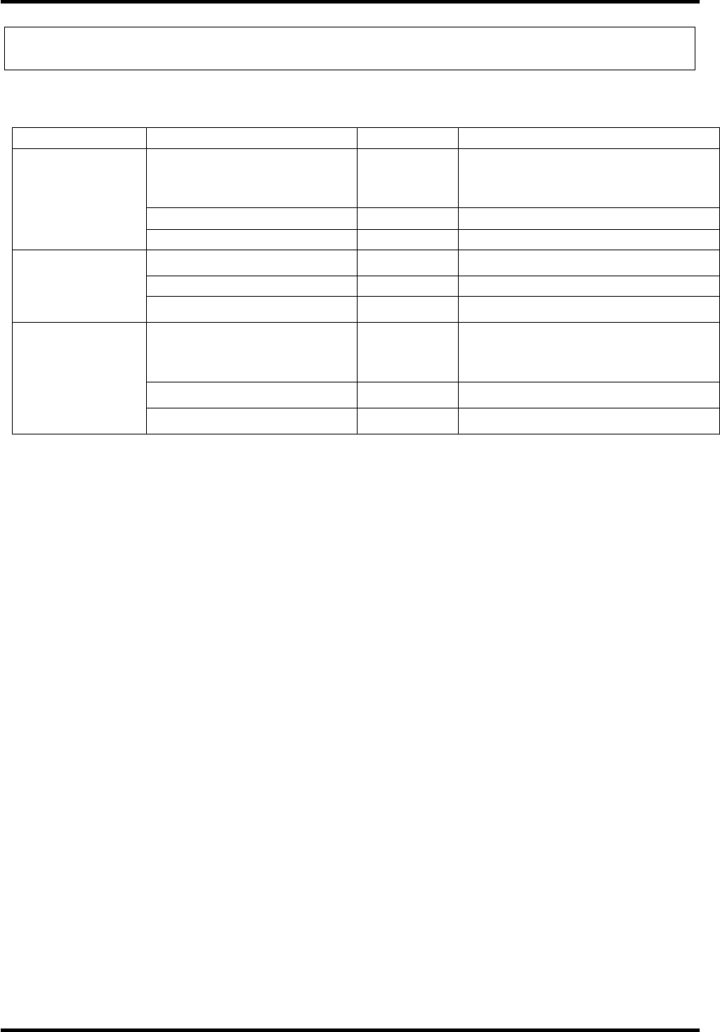
Applicable Standards and Regulations
Standards and Regulations in Other countries
Standards Applicability Remarks
FCC (USA) ✔ *1 FCC Part 15 Subpart C
M18 FCC ID : PZWAN22R01
M30 FCC ID : PZWAN23R01
R&TTE (Europe) ✔ *1 EN 302 291-1, -2
Radio Regulations
RSS-Gen RSS-210(Canada) n/a
EC/R&TTE Directive (Europe) ✔ *1 EN 301 489-1, -3
ICES-003 (Canada) n/a
EMC Regulations
EMC Framework (Australia) n/a C-Tick
UL (USA) ✔ UL508(Type4X Indoor Use Only)
Product ID: 46XM
INDUSTRIAL CONTROL EQUIPMENT
c-UL (Canada) ✔ CSA C22.2 No.142
Safety Regulations
R&TTE (Europe) ✔ EN 60950
✔: Applicable n/a: Not applicable
*1 NOTICE:
Properly shielded and grounded cables must be used for connection to host computer and / or peripherals in order to
meet FCC/CE emission limits.

iii
About this Manual
• The content of this manual may be subject to change for specification improvement without prior notice.
• The reproduction or duplication of the whole or part of this manual is strictly prohibited without prior consent.
• Every attempt has been made to ensure that the content of this manual is thorough and up to date, however, we
kindly ask that any questionable content, mistakes, or omissions be reported to DENSO WAVE.
• The copyright for this User’s Manual belongs to DENSO WAVE INCORPORATED.
Manual Composition
This manual consists of the following 7 chapters.
Safety Precautions
Explains the safety precautions for preventing accidents that could result in bodily injury and property
damage.
Chapter 1 Outline
Explains the hardware and system configuration.
Chapter 2 Basic Specifications
Explains the basic specifications.
Chapter 3 Power Supply Specifications
Explains the power supply specifications.
Chapter 4 Upper Communication Specifications
Explains the interface specifications.
Chapter 5 Tag Communication Specifications
Explains the RF interface specifications and communication distance.
Chapter 6 Installation
Explains the environmental conditions and setups.
Chapter 7 Troubleshooting
Explains possible causes and appropriate countermeasures of troubles.
iv
SAFETY PRECAUTIONS
Be sure to observe the safety precautions.
Read through this manual carefully. It will enable you to use the product correctly.
Always keep this manual in a handy place for easy reference.
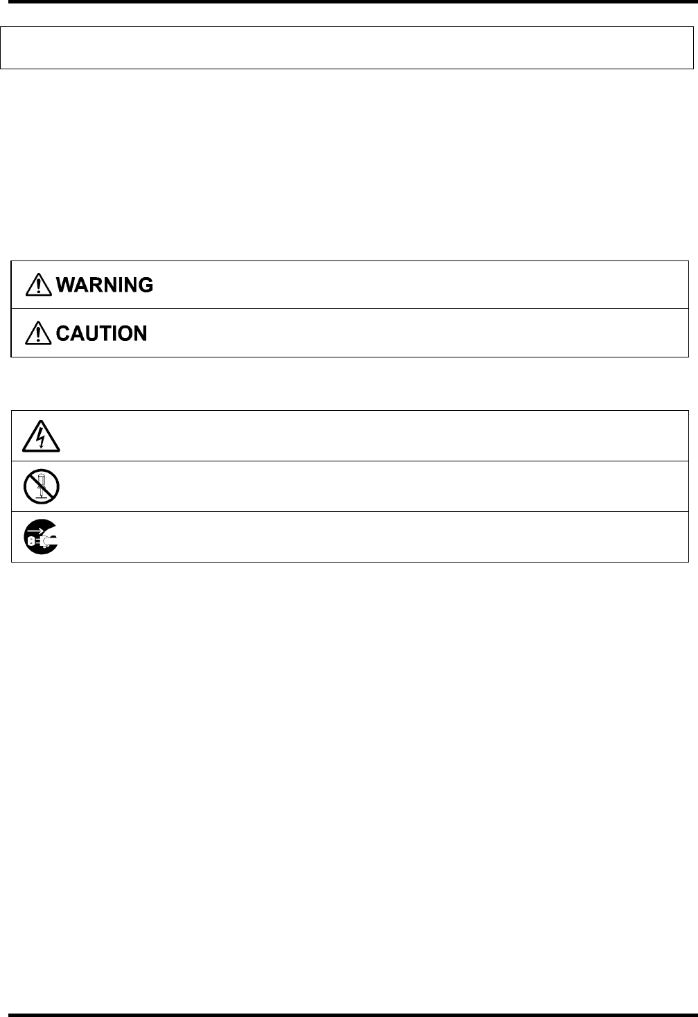
Strict observance of these warnings and cautions is a MUST for preventing accidents that could result in bodily injury
and property damage. Make sure you fully understand all definitions of these terms and symbols given below before
you proceed to the text itself.
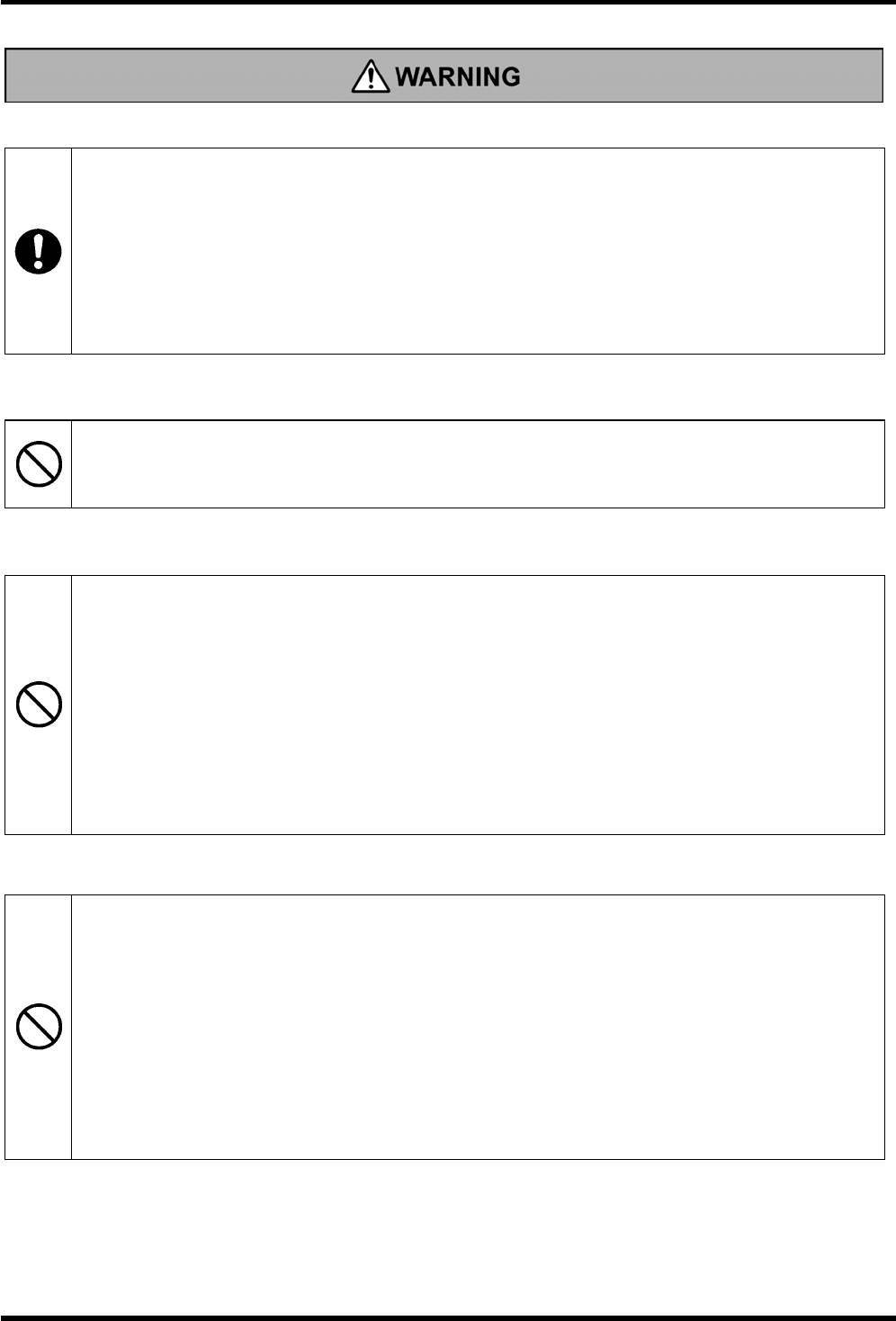
Indicates a potentially hazardous situation which could result in death or serious injury, if the
instructions are not followed correctly.
Indicates a potentially hazardous situation which may result in injury, if the instructions are not
followed correctly.
Meaning of Symbols
Indicates a warning of danger.
The example indicates the warning for electrical shock.
Indicates what you are prohibited to do.
The example Indicates that you are not allowed to disassemble.
Indicates what you MUST do without fail.
The example indicates that you MUST unplug the power cord.
v
Implantable Medical Devices
• Avoid using the product near persons with implantable medical device, such as a cardiac
pacemaker.
A survey conducted on wireless card systems has reported the possibility of affecting or giving
unfavorable impact on implantable medical devices.
This is a general characteristic of those systems using radio waves, and not a unique feature of
DENSO WAVE’s products or this product itself.
More information is available from the website by Ministry of Internal Affairs and Communications
at: http:www.soumu.go.jp/s-news/2003/030620_1.html.
Radio Frequency Interference
• Do not use the product in places where the use of radio frequency is restricted, such as in an
airplane or hospital.
Failure to comply could cause a malfunction in electronic or medical devices.
Operating Environments
• Do not use the product in places where any inflammable gases may be emitted.
Failure to comply could cause a fire.
• Do not use the product in places where an ambient temperature exceeds the specified operating
temperature.
Failure to comply could cause a fire.
• Do not use the product where it is subject to substantial vibration or shock.
Failure to comply could cause a malfunction or a fire.
• Do not use the product where it is subject to oil or chemical contact.
Failure to comply could cause a malfunction or a fire.
Precautions when Handling
• Do not use a power supply and voltage other than the specified power supply and voltage.
Failure to comply could cause a malfunction or a fire.
• Do not pull on the cable.
A loose cable could cause a fire or electrical shock.
• Keep the product away from water or steam.
If the connector gets wet, this could cause a fire, electrical shock, or a faulty connection.
• Do not damage, over bend, twist, pull, or heat the connection cable and device cable.
Do not place heavy material on the cables or allow them to be damaged under heavy material.
Failure to comply could cause the cables to break, and cause a fire or electrical shock.
vi
Precautions when Handling
• Connect the cable to the connector firmly with a clamp.
A loose cable could cause a fire or electrical shock.
• Replace the damaged cable to a new one, when a connection cable or a device cable are
damaged (e.g., exposed or broken lead wires).
Failure to comply could cause a fire or electrical shock.
• Wiring to the power supply and the upper device must be done correctly in accordance with this
manual.
Incorrect wiring could cause amalfunction, a fire, or electrical shock
• If smoke, abnormal odors or noises come from the product, immediately turn the product off.
Failure to comply could cause fire or electrical shock.
• If foreign material or water gets into the product, immediately disconnect the connection cable.
Failure to
comply could cause fire or electrical shock.
• If the product is dropped or damaged, immediately disconnect the connection cable.
Failure to
comply could cause fire or electrical shock.
vii
Operating Environments
• Never leave the product in places where there are excessively high temperatures, radiant heat, or
in places exposed to direct sunlight.
Failure to comply could affect the parts, and cause a fire.
• Do not use the product in places where there are drastic temperature changes.
Failure to comply could cause a malfunction, a fire or electrical shock.
• Do not install the product near a motor, an inverter, or a switching power supply.
Noise from these devices could interfere with the wireless communication between the product and the
tag.
Examine these noises carefully before the product is installed.
• Keep the product or the connection cable away from high voltage and high current wiring.
Failure to comply could cause a wireless communication error between the transceiver and tag, or
between the transceiver and the upper device.
• Keep the appropriate distance specified in this manual between the transceiver and tag to avoid any
interference.
Failure to comply could cause a wireless communication error between the transceiver and tag.
Precautions when Handling
• Never touch the connector terminals.
Failure to comply could damage the product by ESD.
• Do not apply static electricity to the connector terminals and product itself when installing or wiring
the product.
Failure to comply could cause a fire or electrical shock.
• Do not pull the connector cable.
Failure to comply could disconnect the cable, damage the product inner part, burn the product, or
cause a fire, or electrical shock.
• Do not use chemicals or oil which may affect the material of the product.
Failure to comply could damage the product.
• Never disassemble or modify the product.
Failure to comply could cause a fire or electrical shock.
• When pluging/unplugomg the connector, always turn the product off.
Failure to comply could cause malfunction, electrical shock or breakdown.
• Do not touch the product with bear hands when operating or right after operation.
Failure to comply could cause a burn.
• Install the product making sure it is not loose by tightening the screw within the torque specified in
this manual.
Failure to comply could cause a damage or malfunction.
• If you are not using the product for a long time, be sure to unplug the connection cable for safety.
Failure to comply could cause a fire.
• When maintaining the product, unplug the connection cable for safety.
Failure to comply could cause electrical shock.
if used in a manner not specified by the manufacturer, the protection provided by the equipment may be impaired.
1
Chapter 1 Outline
1.1 Hardware Configuration
This product line (hereinafter referred to as the Transceiver) is developed for the Rockwell Automation
“1732 series” products to read and write the HF (High Frequency) RFID tag.
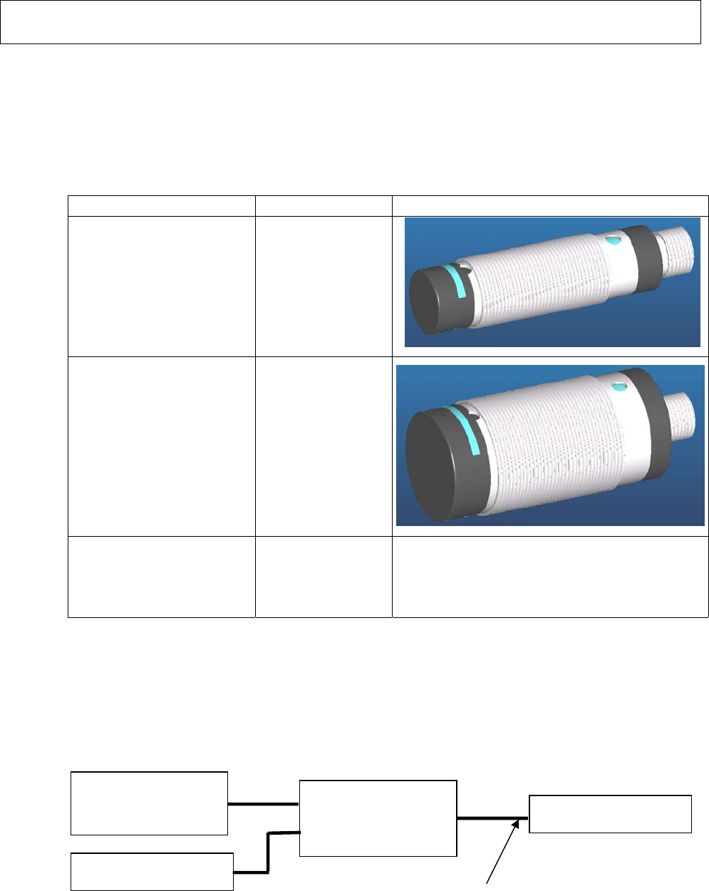
As listed below, two versions of the transceivers are added.
type model appearance
M18 type transceiver 56RF-TR-M18
M30 type transceiver 56RF-TR-M30
Nut, Washer
(Attachment)
- T.B.D
1.2 System Configuration
The transceiver is intended to operate in the following system configuration.
Programmable
Controller (PLC)
DC24V Power Supply
I/F Box
(equivalent to ”1732”) Transceiver
Shielded Cable
2
Chapter 2 Hardware Specifications
2.1 M18 Type Transceiver
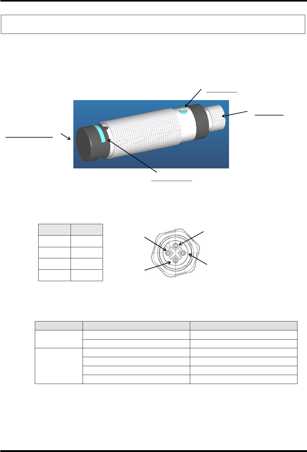
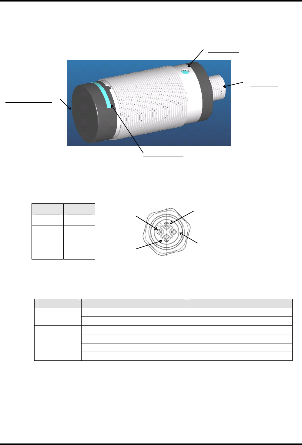
2.1.1 Components and Functions
・Connector
Pin No. Signal
Pin1 DC24V
Pin2 S +
Pin3 GND
Pin4 S -
・LED light patterns
LED Light Explanation
Solid Green Power ON
Power LED No light Power OFF
Blinking Red (short intervals) Nothing Communication
Solid Green Polling (No RFID tag)
Solid Orange Communication OK
Operation LED
Solid Red Communication Error / No RFID tag
Power LED
Operation LED
Connector
Antenna surface
Pin1
Pin2
Pin3 Pin4
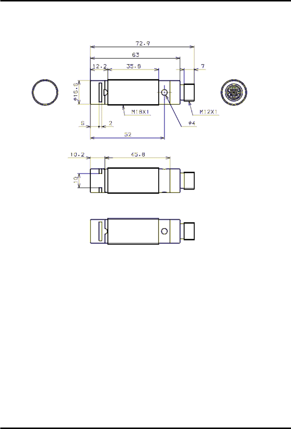
3
2.1.2 External Dimensions
Unit: mm
4
2.1.3 Environmental specifications
Item Specification
Maximum surrounding air
temperature rating
70℃
Minimum surrounding air
temperature rating
-25℃ (With no icing or condensation)
Operating Humidity 35 to 95%RH (With no icing or condensation)
Storage Temperature -40℃ to +85℃ (With no icing or condensation)
Storage Humidity 25 to 85%RH (With no icing or condensation)
Insulation Resistance 20M Min. (DC500V Mega)
Between connector terminals and case
Vibration Resistance 10 to 500Hz, 1.5mm double amplitude, acceleration: 100m/s2,
10 sweeps in each of 3 axis directions
(up/down, left/right, and forward/backward) for 11 minutes each
Shock Resistance 500 m/s2 in 6 directions 3 times each (18 times in total)
Protective Structure IP67 (Excluding connector area)
Altitude Less than 2000m
Pollution degree Level 2 (IEC61010-1)
Material Plastic chassis: Grass fiber composite PBT (Black color)
Metal chassis and M12 cable connector: Nickel Plated S45C
Weight 30g
5
2.2 M30 Type Transceiver
2.2.1 Components and Functions
・Connector
Pin No. Signal
Pin1 DC24V
Pin2 S +
Pin3 GND
Pin4 S -
・LED light patterns
LED Light Explanation
Solid Green Power ON
Power LED No light Power OFF
Blinking Red (short intervals) Nothing Communication
Solid Green Polling (No RFID tag)
Solid Orange Communication OK
Operation LED
Solid Red Communication Error / No RFID tag
Pin1
Pin2
Pin3 Pin4
Power LED
Operation LED
Connector
Antenna surface
6
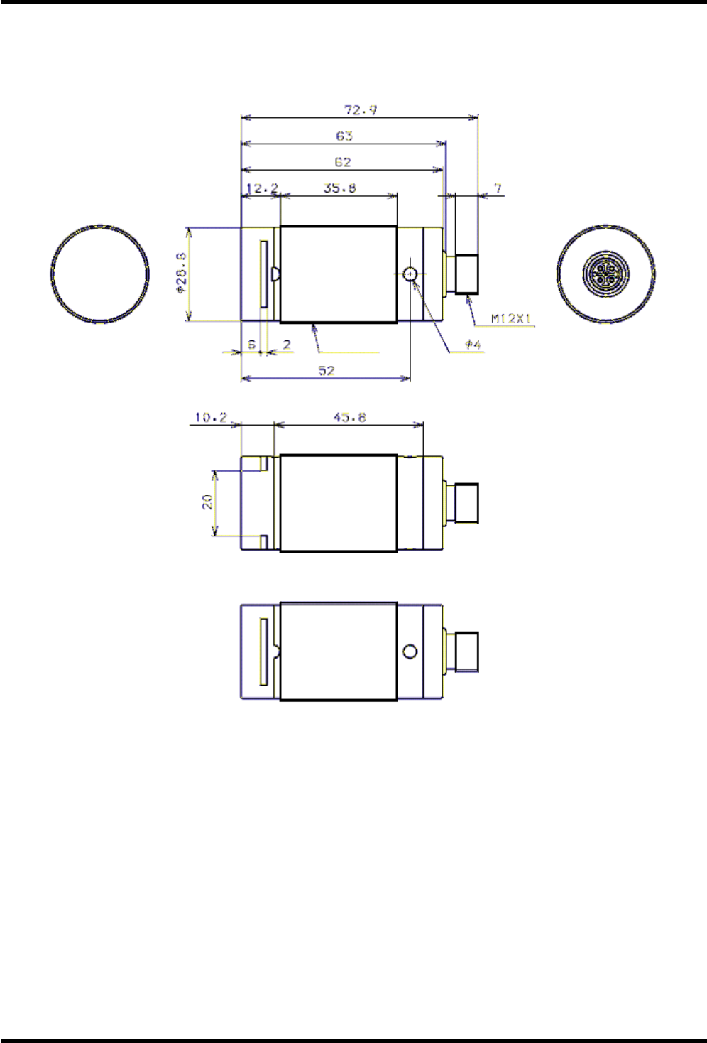
2.2.2 External Dimensions
Unit: mm
M30×1.5
7
2.2.3 Environmental specifications
Item Specification
Maximum surrounding air
temperature rating
70℃
Minimum surrounding air
temperature rating
-25℃ (With no icing or condensation)
Operating Humidity 35 to 95%RH (With no icing or condensation)
Storage Temperature -40℃ to +85℃ (With no icing or condensation)
Storage Humidity 25 to 85%RH (With no icing or condensation)
Insulation Resistance 20M Min. (DC500V Mega)
Between connector terminals and case
Vibration Resistance 10 to 500Hz, 1.5mm double amplitude, acceleration: 100m/s2,
10 sweeps in each of 3 axis directions
(up/down, left/right, and forward/backward) for 11 minutes each
Shock Resistance 500 m/s2 in 6 directions 3 times each (18 times in total)
Protective Structure IP67 (Excluding connector area)
Altitude Less than 2000m
Pollution degree Level 2 (IEC61010-1)
Material Plastic chassis: Grass fiber composite PBT (Black color)
Metal chassis and M12 cable connector: Nickel Plated S45C
Weight 55g
8
Chapter 3 Power Supply Specifications
3.1 Supply Voltage and Current Consumption
Item Specification
Supply Voltage DC24V
(DC10 to 30V, Ripple is less than 1%)
Carrier off 10mA at.DC24V (Excluding inrush)
M18 type 40mA (Max. 0.1A)
at DC24V
Current Consumption Carrirer on
M30 type 40mA (Max. 0.1A)
at DC24V
* Power Suplly : UL1310 Class2,
IEC61010-1 Limited energy circuit
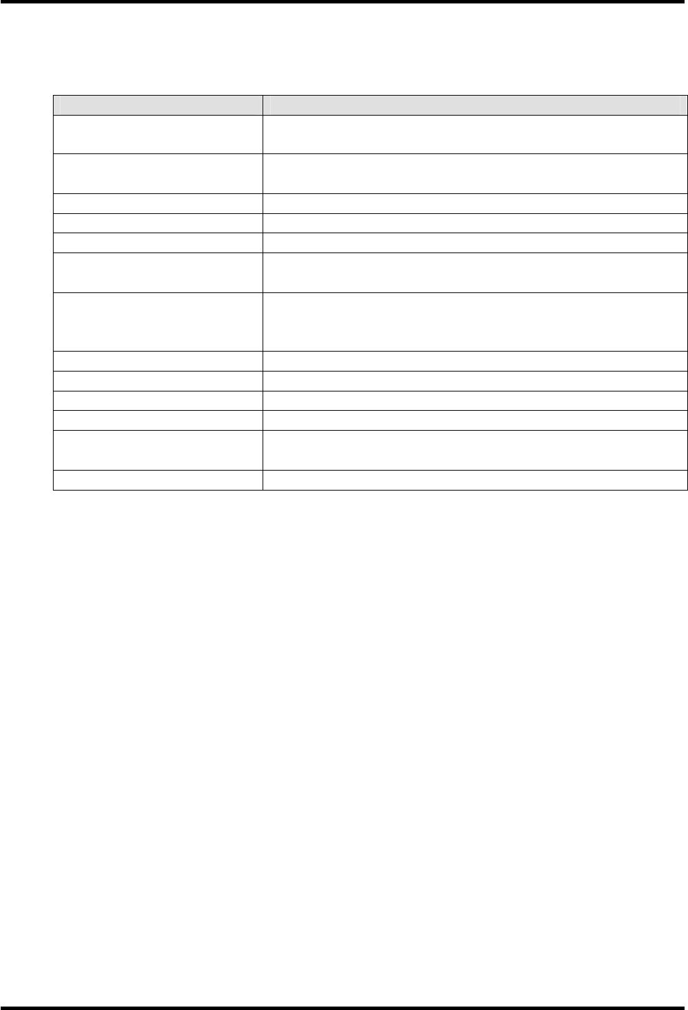
3.2 Inrush Current (reference value)
*The waveform and values in the above figure are reference values at room temperature.
Inrush Current
Waveform
Power ON
approximately
10mA
(20A)
9
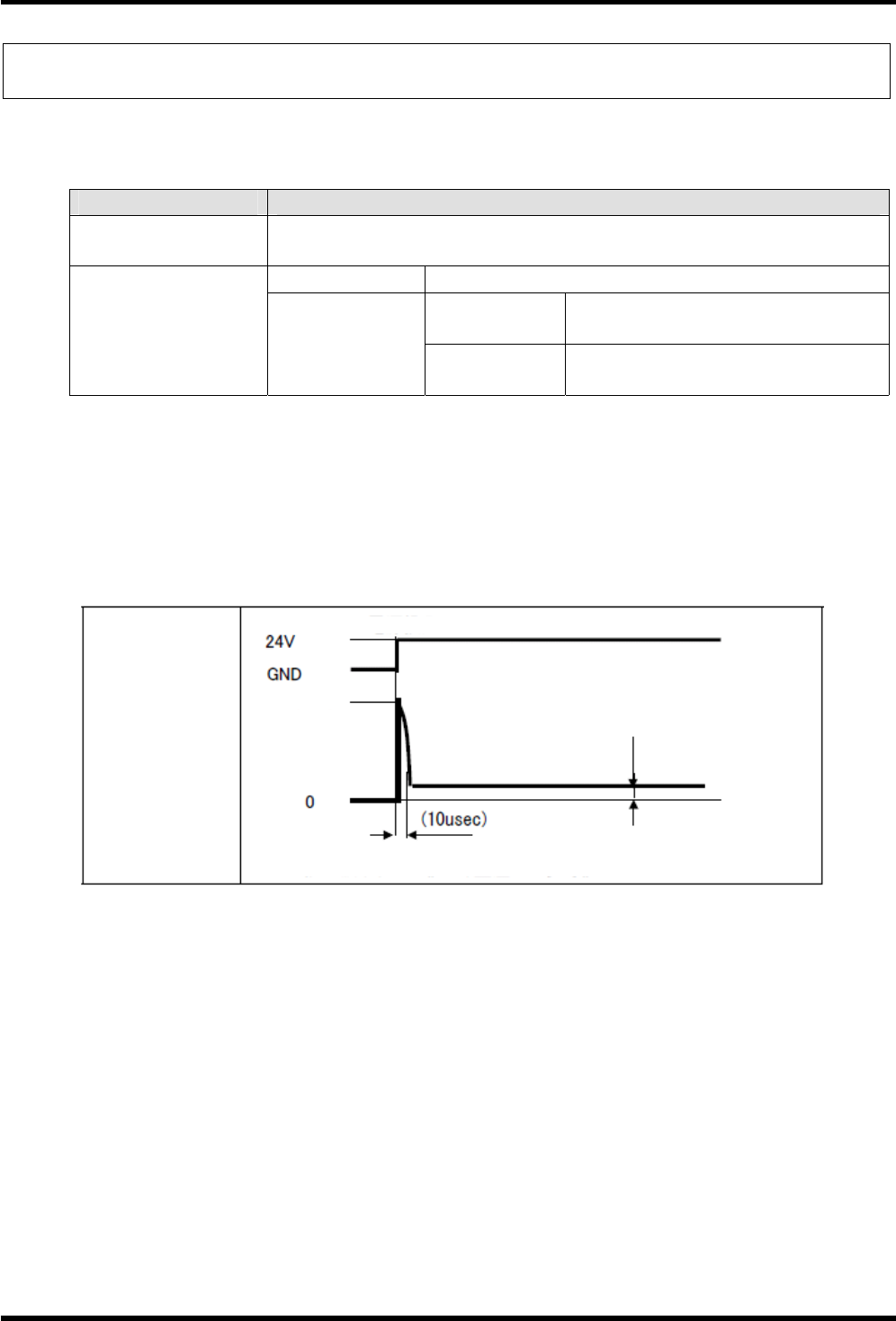
3.3 Power OFF Duration
OFF duration (referred to as “TvccOFF” in the figure) is required to re-power ON.
“TvccOFF” must be (1 second) or more.
ON duration (referred to as “TvccON” in the figure) is required before sending any command to the
transceiver.
“TvccON” must be (0.5 second) or more.
Item Description Condition Time
TvccOFF Required OFF duration to re-power ON TvccFall=0ms (1 sec)
TvccON Required ON duration to complete start up
after completion of power-on (TvccRise).
TvccRise≦
10ms (0.5sec)
3.4 Power Supply Protection Circuit
The transceiver does not have any power supply protection circuits.
Add the following protection circuits to the host device as necessary.
・Over current protection circuit
・Over voltage protection circuit
Add appropriate countermeasures for noise as necessary.
Power ON
Power OFF completion of
startup

10
Chapter 4 Upper Communication Specifications
4.1 Specifications to communicate with the host device
Item Specification
Connector M12, 4-pin male connector
Communication System Half Duplex (RS-485)
Baud Rates 9600/19200/38400/115200bps selectable
(Default: 38400bps)
Data Length 8bit
Stop Bit Length 1bit
Error Detection Parity bit even
Cable Length Max. 100m (It varies in the cable)
Note:
・RS485 Protocol: Switch the command-response mechanism to avoid signal conflict.
・For more information, see the communication and interface specification.
・For changing the transmission speed, see the programming manual.
-Important-
(When Flash-ROM is rewritten,) Do not change the transmission speed more than 100 times.
11
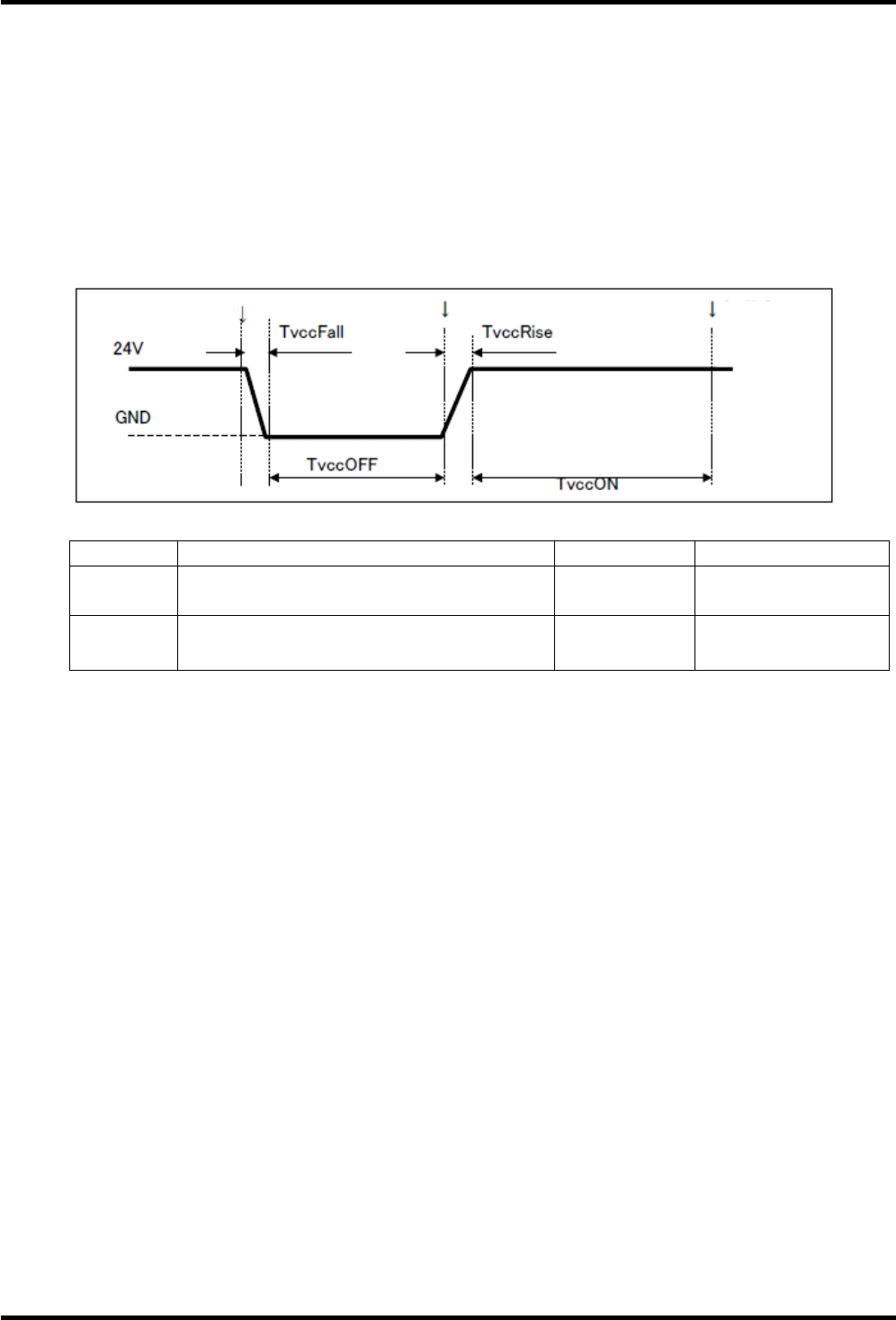
4.2 I/F Circuit
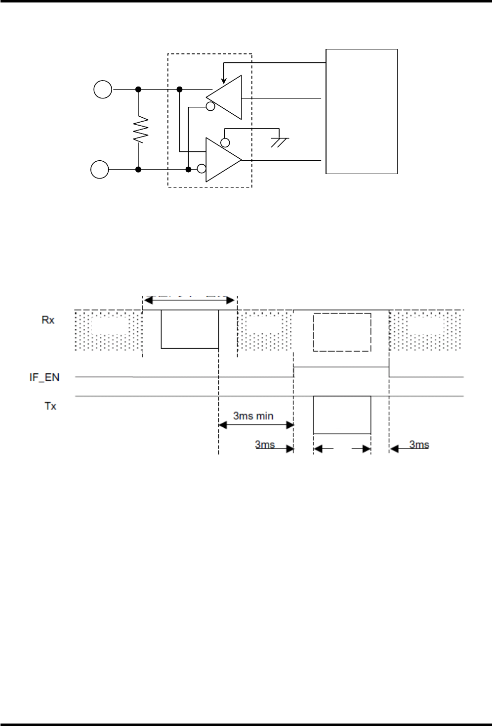
4.3 Response Timing
variable variable variable
Command Command
Response
Out
p
ut form the u
pp
er drive
r
S+
S-
D
R
CPU
Rx
120ohm
IF EN
Tx
12
Chapter 5 Tag Communication Specifications
5.1 Specifications to communicate with the RF tag
The following is the communication specifications between the transceiver and the RFID tag.
Item Specification
Tag Type ISO/IEC 15693
Communication System Half Duplex
Synchronization scheme Bit Synchronization
Baud Rate 26.48kbit/s (Carrier:13.56MHz)
Modulation Scheme ASK 10 to 30%
Transceiver
↓
Tag Modulation code 1 out of 4
Baud Rate OOK 26.48kbit/s (Sub Carrier:424kHz)
Modulation Scheme Load Modulation
Tag
↓
Transceiver Modulation code OOK Manchester
Note:
For details of the command and communication period, see the programming manual.
5.2 Communication Distance
communication distance
(at room temperature)
Transceiver 50 tag
(I-Code)
30 tag
(I-Code)
20 tag
(I-Code)
16 tag
(I-Code)
M18 type 30mm - - -
M30 type 60mm - - -
・Noise Interference, metals, and other transceivers are not allowed around the transceiver.
・Communication distance may be shorter than the above value due to the tag deviation.
・Must not be any slant between the transceiver and the antenna center of the tag.
13
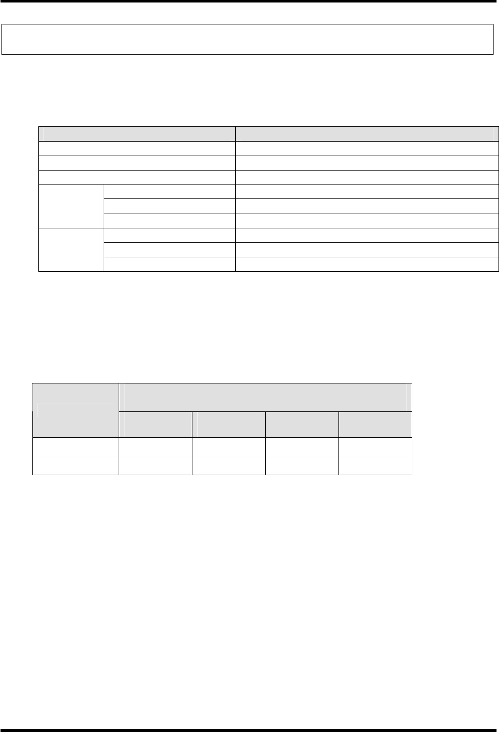
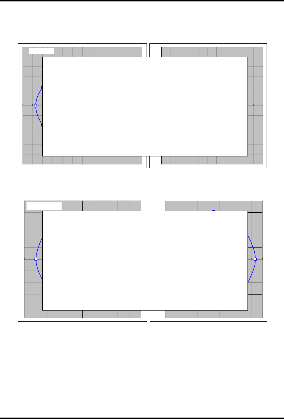
5.3 Communication Area (reference)
M18 Type
*
50 tag
M30 Type
*
50 tag
* It isn't mentioned in the Side-Band-Area.
-100
-80
-60
-40
-20
0
20
40
60
80
100
0 20 40 60 80 100 120 140 160 180
-100
-80
-60
-40
-20
0
20
40
60
80
100
-10
0
-80 -60 -40 -20 0 20 40 60 80 100
distance 60mm [mm]
[mm]
-60
-50
-40
-30
-20
-10
0
10
20
30
40
50
60
0 102030405060708090100110
-60
-50
-40
-30
-20
-10
0
10
20
30
40
50
60
-60 -50 -40 -30 -20 -10 0 10 20 30 40 50 60
distance 40mm
[mm]
[mm]
T.B.D
T.B.D
14
Chapter 6 Installation
6.1 Tightening Torque
The tightening torque must be 19.8N・m for M18 nut, and 33.9N・m for M30 nut.
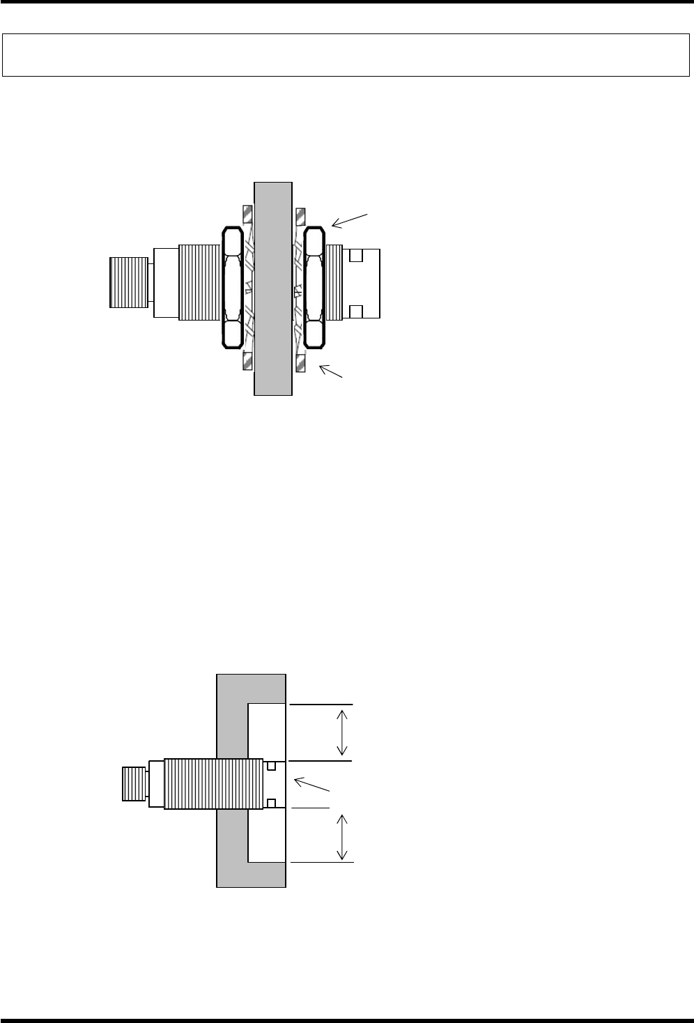
6.2 Surrounding Metal
M18 Type: Communication distance will drop significantly when the distance between the transceiver
and any surrounding metal is less than 25mm.
M30 Type: Communication distance will drop significantly when the distance between the transceiver
and any surrounding metal is less than 30mm.
Nut
For M18: more than 25mm
For M30: more than 30mm
Washer
For M18: more than 25mm
For M30: more than 30mm
Antenna
15
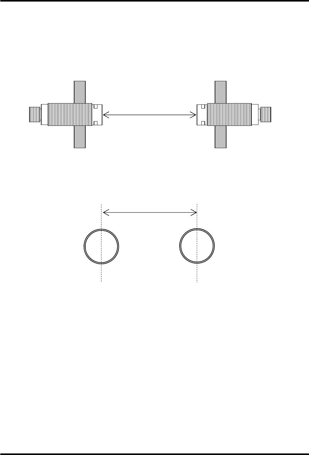
6.3 Interference between the transceivers
Installing more than one transceiver causes radio frequency interference and may result in the difficulty
of the tag communication.
Keep a sufficient distance between the transceivers as shown in the figure below.
・face to face
・side by side
For M18: more than 180mm
For M30: more than 200mm
For M18: more than 180mm
For M30: more than 200mm
16
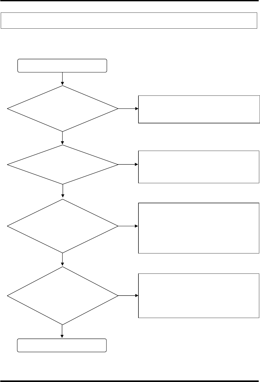
Chapter 7 Troubleshooting
Examine the cause of the problem by using the flowchart below and take appropriate countermeasures when any
problems occur.
Check flow
Do the operating and
environmental conditions
comply with the
specifications?
Is the transceiver installed
correctly?
Does the transceiver
communicate with the upper
device normally?
(Is the transceiver’s LED in
RED?)
Does the transceiver
communicate with the tag
normally?
(Is the transceiver’s LED in
RED?)
Read “Chapter 2 Hardware Specifications” ,
and confirm that the transceiver is used in the
proper operating and environmental conditions.
Read “Chapter 3 Power Supply Specifications”,
“Chapter 4 Upper communication Specifications”,
and confirm that the transceiver is installed and
connected correctly.
A communication error with the upper device has
occurred or RFID Tag doesn't exist when the
transceiver’s LED is in RED.
Confirm the problem with the status code
contained in the transceiver’s response.
See the Programming Manual for the
communication error code.
OK
NO
NO
NO
NO
A communication error with the tag has occurred
when the transceiver’s LED is blinking in RED.
Confirm the problem with the status code
contained in the transceiver’s response.
See the Programming Manual for the
communication error code.
YES
YES
YES
YES

M18 type transceiver (56RF-TR-M18)
M30 type transceiver (56RF-TR-M30)
for 1732 series
User’s Manual
Ver : 0.92 Jul. 2012
1, Yoshiike, Kusagi, Agui-cho, Chita-gun, Aichi 470-2297, Japan 105-0001
http://www.denso-wave.com/