Detex Installation Instructions For 03W Advantex Trim 101260
User Manual: Detex Installation Instructions for 03W Advantex Trim Installation Instructions
Open the PDF directly: View PDF ![]() .
.
Page Count: 4
Detex Corporation, 302 Detex Drive, New Braunfels, Texas 78130-3045
(830)629-2900 / 1-800-729-3839 / Fax (830)620-6711
E-MAIL: detex@detex.com INTERNET: www.detex.com
101260 May 29, 2007
INSTALLATION INSTRUCTIONS FOR 03W ADVANTEX TRIM
DETEX INS-101260
TOOLS AND SUPPLIES
Safety Glasses
(Always put on safety glasses prior to beginning installation of unit)
Pencil
Center Punch
Hammer
Drill Motor
Drill Bits & Taps
Screw Driver (Phillips Drive)
Tape Measure
PREPARING THE TRIM:
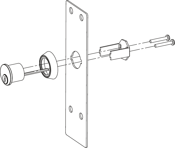
1. Assemble the cylinder bracket and cylinder as shown (Fig. T1). Cut cylinder screws as
required.
PREPARING THE DOOR:
1. Center punch hole "a" marked earlier.
2. Drill two (2) pilot holes "a" (holes located diagonal from each other). Caution: Be sure to
drill STRAIGHT through the door.
3. Drill pilot holes for remaining holes "a" through inside of door only.
4. Using the backplate as a template on the outside door face, align the two through-holes.
Mark and center punch the two (2) remaining holes "a".
5. Note: Verify that the slotted edge of the backplate faces the edge of the door. Mark the
outside trim cam hole "d".
6. Drill pilot holes "a" through outside of door only.
7. Drill four (4) 3/8" holes partway through the door. Complete these holes by drilling from the
opposite door face.
Page 2
Fig. T1
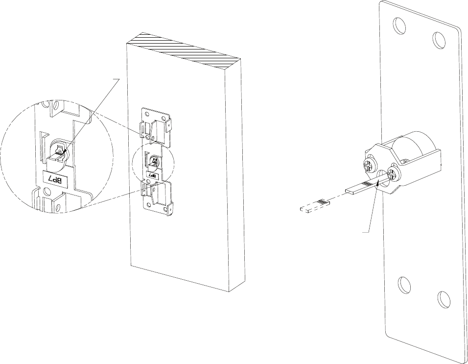
MARK TAILPIECE HERE
CUT THIS SIDE OF MARK
Fig. T2A Fig. T2B
8. At the outside trim cam hole "d", measure up 1/4" and make a new mark. This will be the
center of the outside trim cylinder. Center punch and drill a 1-1/2" hole. Repeat for inside of
door.
ASSEMBLING THE OUTSIDE TRIM AND BACKPLATE:
1. Place the trim assembly against the door, aligning the cylinder tailpiece through the backplate
trim cam.
2. Mark the tailpiece as it protrudes through the cam (see Fig. T2A).
3. Remove trim assembly and cut the tailpiece just inside of the mark (see Fig. T2B). Caution:
Tailpiece must not extend past the cam.
Page 3
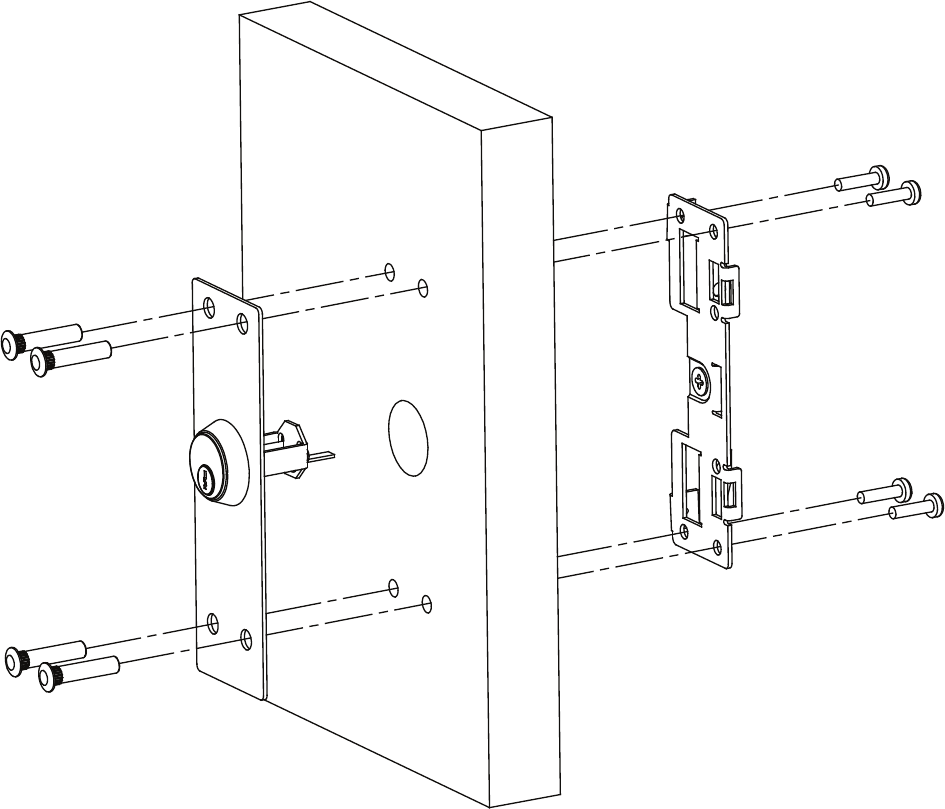
4. Align the four sex nuts and trim assembly through the drilled holes (Fig. T3).
5. With the key out of the cylinder, align the tailpiece extension into the backplate's trim cam on
the inside door face.
6. It may be necessary to hammer the sex nuts into the door face.
7. Fasten the backplate to the inside door face with 1/4-20 machine screws provided. Caution:
Do not overtighten.
8. Key should turn freely in both counter clockwise and clockwise directions.
9. Resume with panic hardware instruction #15.
Fig. T3
Page 4
