Device Solutions PA0002 Sensor Board Module User Manual Installation Instructionsx
Device Solutions Inc. Sensor Board Module Installation Instructionsx
Users Manual

DeviceSolutions
Collector&Sensor
InstallationInstructions
RevisionHistory:
PRELIMINARY

FCCCaution:
Changes or modifications not expressly approved by Device Solutions could void the user’s authority to operate
this equipment.
Note: This equipment has been tested and found to comply with the limits for a Class B digital device, pursuant
to part 15 of the FCC Rules. These limits are designed to provide reasonable protection against harmful
interference in a residential installation. This equipment generates, uses and can radiate radio frequency energy
and, if not installed and used in accordance with the instructions, may cause harmful interference to radio
communications. However, there is no guarantee that interference will not occur in a particular installation. If this
equipment does cause harmful interference to radio or television reception, which can be determined by turning
the equipment off and on, the user is encouraged to try to correct the interference by one or more of the
following measures:
Reorient or relocate the receiving antenna.
Increase the separation between the equipment and receiver.
Connect the equipment into an outlet on a circuit different from that to which the receiver is connected.
Consult the dealer or an experienced radio/TV technician for help.
CollectorInstallation
1. ProvisiontheCollectorintheserver
2. Removethefour3/8”#4screwsintothecornersof
theenclosuretopthatfastenittotheenclosure
base.
3. Connectthebattery
4. Reinstallthefour3/8”#4screwsintothecornersof
theenclosuretopthatfastenittotheenclosure
base.
5. Attachtheenclosuretoasurface.ThebestRF
performanceisobtainedbymountingtheCollector
toaverticalservice.
6. Connectexternalpowertothecollector
SensorInstallation
1. RemovethescrewsthatholdthetopoftheSensor's
enclosuretothebase
2. VerifythesignalstrengthattheSensor
a. OpentheCollectorpressthebuttontoenter
"installmode".
b. WaitfortheinternalgreenLEDtoilluminate.
c. ReboottheSensorbyremovingandre‐installing
the9voltbattery
d. PlacetheSensorwithin50feetlineofsightofthe
Collector
e. WaitfortheSensor'sinternalLEDtoilluminate
(upto1minute)
f. ThecoloroftheLEDindicatesthefollowing(red–
poorsignalquality,yellow–moderatesignal
quality,greengoodsignalquality)

g. MovetheCollectorand/orSensoruntiltheSensor
displaysagoodsignalconditionforatleast5
consecutiveseconds
h. Repeatcthroughgforeachsensor
i. Disable"installmode"fortheCollectorby
pressingthebuttononthecollectoragain(ifthis
stepisforgottenthecollectorwillexitinstall
modeinonehour)
j. TurnoffeachSensorbyremovingthe9volt
battery
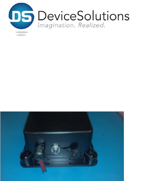
3. Loosenthenutfromthecablerestraintshown
above
4. Passthetransducerwiresthroughthecable
restraint
5. Tightenthecablerestraintnuttothecablerestraint
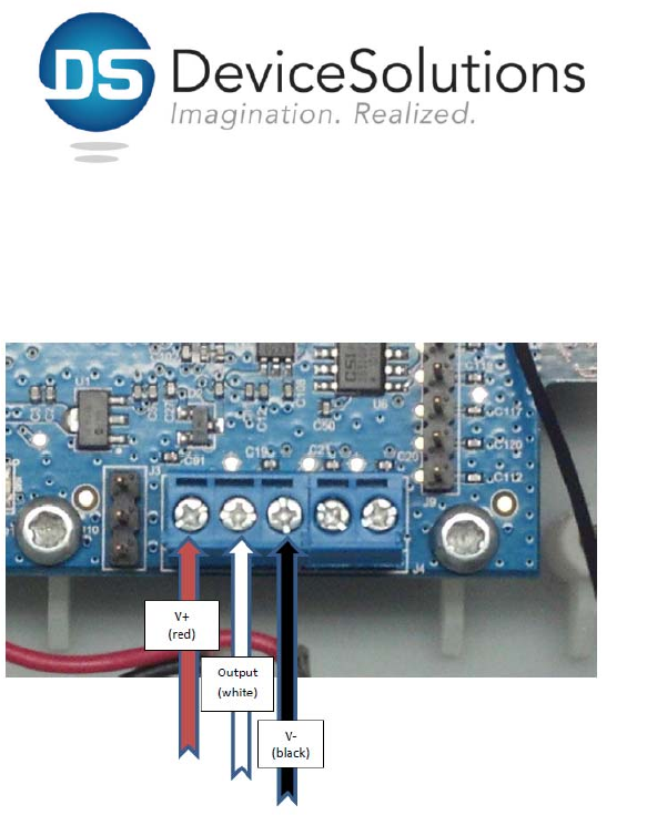
6. Attachthetransducerwirestotheterminalblocks.
Thisconnectiondependsonthetypeoftransducer
used.Seetheappendixforanexample.
7. Thetotallengthofthetransducercablemustbe
lessthan10feet
8. Installthe9voltbatteryinthesensor
9. Re‐installthescrewsthatholdthetopofthe
enclosuretothebase
10. Attachtheenclosuretoasurface.ThebestRF
performanceisobtainedbymountingtheSensor
vertically.

Appendix:
AshcroftPressureTransducerInstallation
Barewire(shielddrainwire)fromthetransduceris
unused.