Digi 50M1312 802.11b transceiver to serial converter User Manual Digi Connect SP and Wi SP Hardware Reference
Digi International Inc 802.11b transceiver to serial converter Digi Connect SP and Wi SP Hardware Reference
Digi >
User Manual
Digi Connect SP &
Digi Connect Wi-SP
Hardware Reference
TM
TM
90000540_C
Digi International Inc. 2003, 2004, 2005. All Rights Reserved.
The Digi logo is a registered trademark of Digi International, Inc.
Digi Connect SP and Digi Connect Wi-SP are trademarks of Digi International, Inc.
NetSilicon, NET+Works, NET+OS, and NET+ are trademarks of NetSilicon, Inc.
All other trademarks mentioned in this document are the property of their respective owners.
Information in this document is subject to change without notice and does not represent a
commitment on the part of Digi International.
Digi provides this document “as is,” without warranty of any kind, either expressed or implied,
including, but not limited to, the implied warranties of fitness or merchantability for a particular
purpose. Digi may make improvements and/or changes in this manual or in the product(s) and/or the
program(s) described in this manual at any time.
This product could include technical inaccuracies or typographical errors. Changes are periodically
made to the information herein; these changes may be incorporated in new editions of the
publication.

5
Contents
About This Guide .....................................................................................................................7
Purpose .............................................................................................................................7
Related Documentation....................................................................................................7
Chapter 1: Introducing the Digi Connect SP & Digi Connect Wi-SP Hardware ............9
Hardware Overview .........................................................................................................9
LEDs...............................................................................................................................11
Reset Button ...................................................................................................................12
Antenna ..........................................................................................................................13
MEI 232/422/485 Switch Settings .................................................................................13
DB-9 Connector .............................................................................................................14
JTAG Interface...............................................................................................................15
Power Jack......................................................................................................................16
Chapter 2: Programming Considerations..........................................................................19
GPIO...............................................................................................................................19
GPIO Pin Use.................................................................................................................21
LEDs...............................................................................................................................21
Flash ...............................................................................................................................22
Memory ..........................................................................................................................22
Reset Button ...................................................................................................................23
Appendix A: Specifications.................................................................................................. 25
Network Interfaces .........................................................................................................25
Serial Interface ...............................................................................................................26
Data Rates (bps) .............................................................................................................26
Flow Control Options.....................................................................................................26

Contents
6
Environmental................................................................................................................ 26
Power Requirements ...................................................................................................... 27
Mechanical..................................................................................................................... 27
Antenna Information...................................................................................................... 28
RF Exposure Statement.................................................................................................. 32
Overlay Specifications................................................................................................... 33
Appendix B: Certifications ................................................................................................. 35
FCC Part 15 Class A ...................................................................................................... 35
Industry Canada ............................................................................................................. 36
International EMC Standards......................................................................................... 37
Appendix C: Change Log.................................................................................................... 39
Revision C......................................................................................................................39

7
About This Guide
Purpose
The purpose of this guide is to assist developers creating custom embedded software for the
Digi Connect SP and Digi Connect Wi-SP platform using the NET+OS operating system
and tools.
Related Documentation
See the NS7520 Hardware Reference for information on the NS7520 chip.
See the NET+Works BSP Porting Guide for additional programming information.

Related Documentation
8

9
Introducing the
Digi Connect SP &
Digi Connect Wi-SP
Hardware
CHAPTER 5
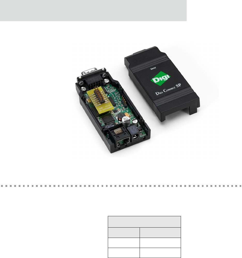
Hardware Overview
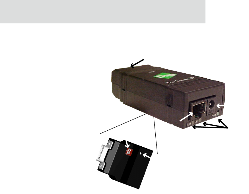
The following figure identifies various Digi Connect SP and Digi Connect Wi-SP
connectors, LEDs and switches.
Hardware Overview
10
Digi Connect SP Hardware Reference
Digi Connect SP Hardware Overview
Note
MEI switches and the Reset button are in the same location for both the Digi
Connect SP and Digi Connect Wi-SP.
LEDs
Ethernet
connector
Power
DB-9
MEI
switch
Reset
button
11
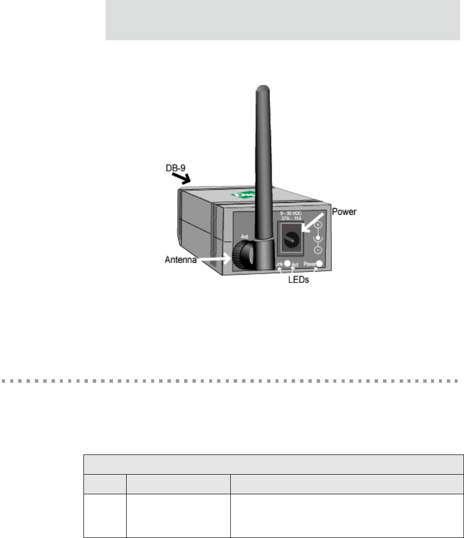
Digi Connect Wi-SP Overview
LEDs
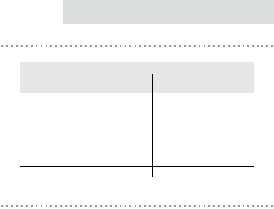
The Digi Connect SP and Digi Connect Wi-SP provide three LEDs. Two of the LEDs are
connected directly to the hardware; the other is software programmable. See the following
table for more information.
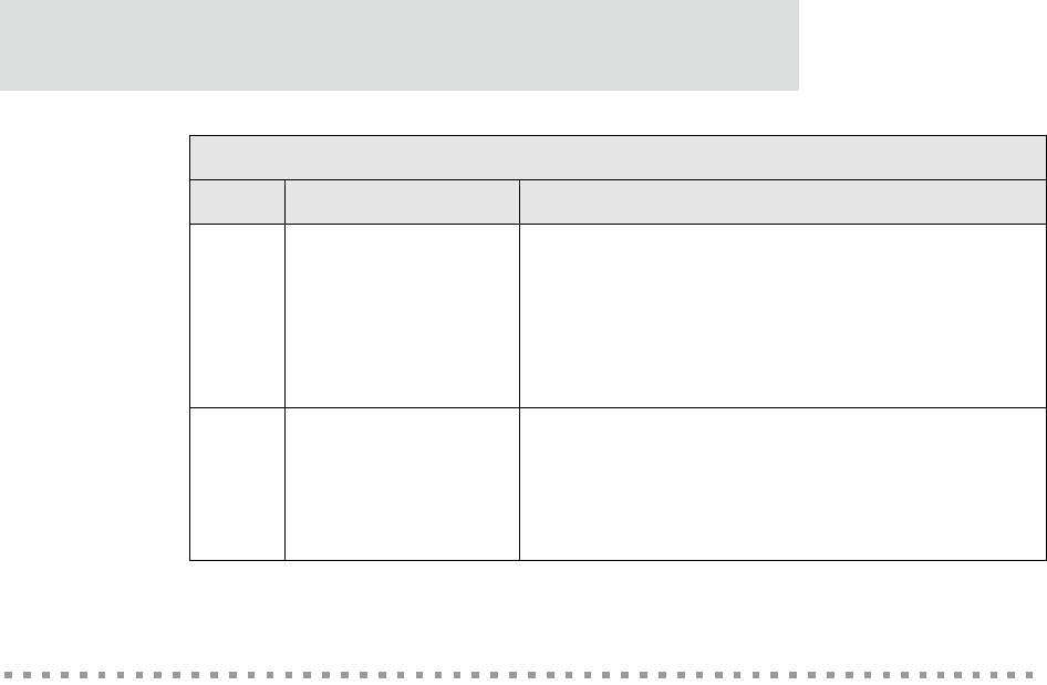
LED Descriptions
LED Color Purpose
Power Red (labeled PWR) This LED is software programmable. The default is that
this LED indicates power (and is therefore always on).
See “LEDs” on page 21 for more information
Reset Button
12
Digi Connect SP Hardware Reference
Reset Button
The behavior of the reset button is user-defined. See “Reset Button” on page 23 and the
NS520 BSP Porting Guide for LED programming information.
Link Green
Network link status:
– On - unit is associated with an access point
– Blinking slowly - unit is in ad hoc mode
– Blinking quickly - unit is scanning for a
network
ACT Yellow
This LED is wired to the Ethernet hardware.
– On indicates bad initialization
–Off indicates ready
– Blinking indicates network activity
LED Descriptions
LED Color Purpose
13
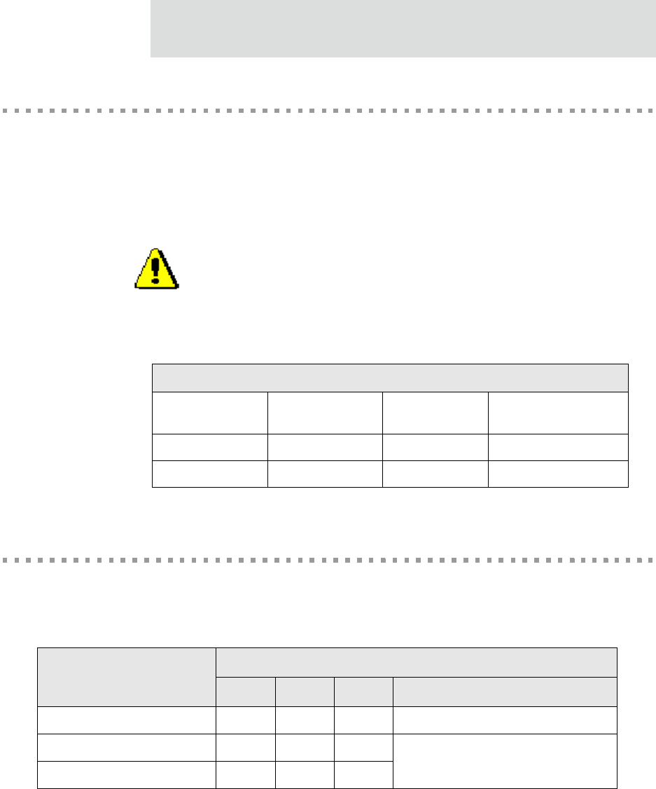
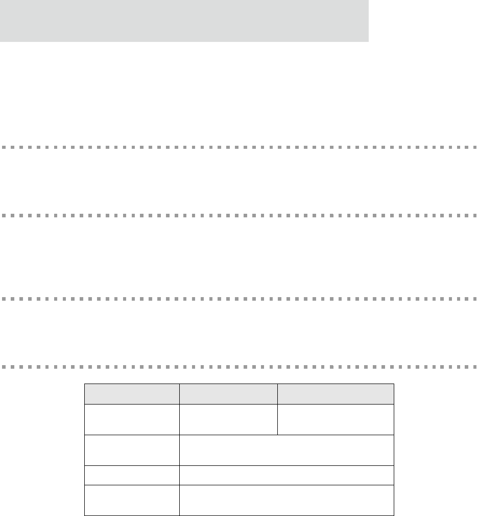
Antenna
The Digi Connect Wi-SP is available with 1 RP-SMA connector. The antenna is connected
to the product with a reverse polarity SMA connector (sub-miniature size A). The antenna
only fits on the product one way to ensure a proper connection. Another option for both
signal reception and design flexibility is to use a 30cm antenna extension cord (Digi part
number DC-ANT-E-24DP) with .5dB loss to separate the antenna from the product..
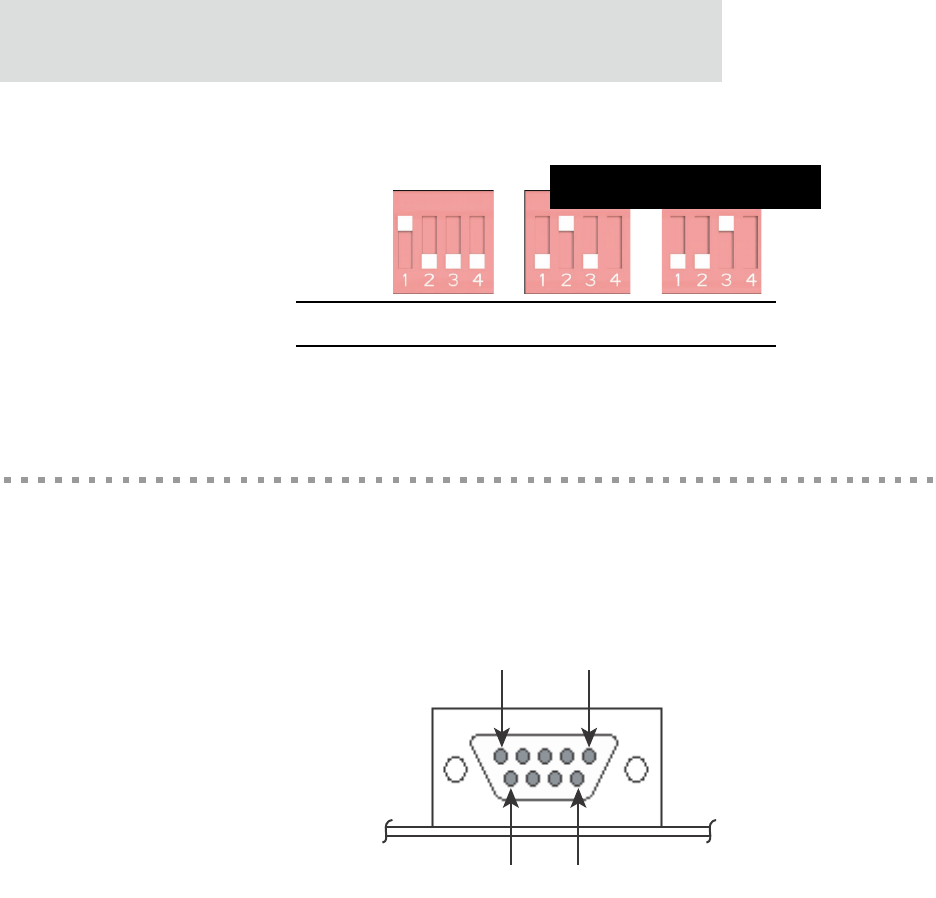
MEI 232/422/485 Switch Settings
These switches set the MEI (multiple electrical interface) line protocol on the serial
interface.
Antenna Description
Type Desktop Dipole 30 cm
Antenna Extension Cord
Part number DC-ANT-24DT DC-ANT-24DP DC-ANT-E-24DP
Gain 1.8 dBi 2 dBi -.5dB
Caution: This Part 15 radio device operates on a non-interference basis
with other devices operating at this frequency when using the antennae
listed in the Antenna Specification table. Any changes or modification to
user’s authority to operate the device.
the product not expressly approved by Digi International could void the
Function Switch Setting
1 2 3 4
EIA-232 Up Down Down Down
EIA-422/485 full-duplex Down Up Down – If up, termination.
– If down, no termination
EIA-485 half-duplex Down Down Up
DB-9 Connector
14
Digi Connect SP Hardware Reference
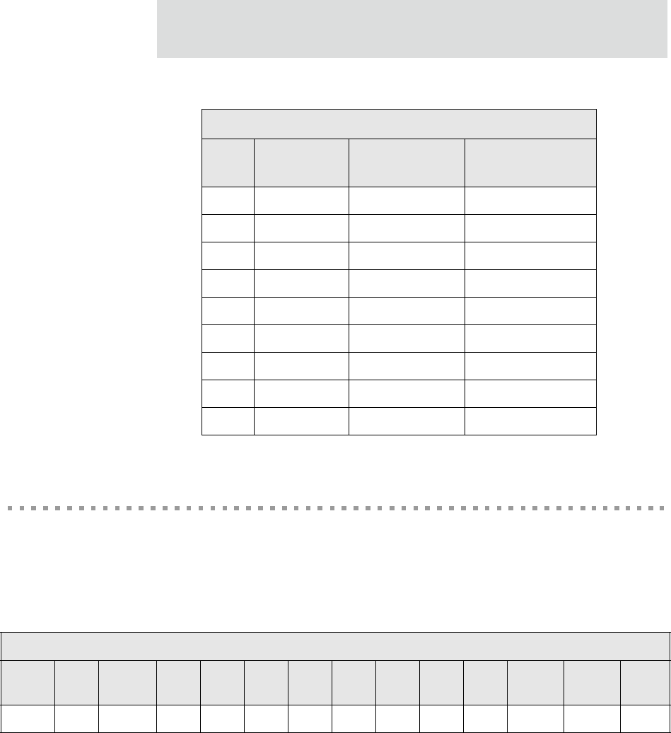
DB-9 Connector
The figure and table provide information on DB-9 pin orientation and pin assignments.
DB-9 Pin Orientation
*If switch 4 is up, termination.
If down, no termination.
Up/On
Down/Off
EIA-232 EIA-422/485
Full-Duplex
EIA-485
Half-Duplex
**
0
0000006
Pin 1 Pin 5
Pin 6 Pin 9
15
JTAG Interface
The Digi Connect SP Development Kit is provided with the case opened, providing access
to the JTAG interface which mates with a JTAG debugger plug (for example, the Macraigor
Raven included in the kit). See the following table for pin assignments on the JTAG adapter
block provided.
DB-9 Pin Assignments
Pin EIA-232 EIA-422/485
Full-Duplex EIA-485
Half-Duplex
1 DCD CTS- Not used
2 RXD RXD+ RXD+
3 TXD TXD+ TXD+
4DTR RTS- Not used
5 GND GND GND
6 DSR RXD- RXD-
7RTS RTS+ Not used
8CTS CTS+ Not used
9NA TXD- TXD-
JTAG Debugger Connector Pin Assignments
Pin
1Pin
2Pin
3Pin
4Pin
5Pin
6Pin
7Pin
8Pin
9Pin
10 Pin
11 Pin
12 Pin
13 Pin
14
VCC+ GND /TRST GND TDI GND TMS GND TCK GND TDO /SRST VCC+ GND
Power Jack
16
Digi Connect SP Hardware Reference
Digi Connect SP JTAG Debugger Connector
Power Jack
The Power Jack is a barrel connector that accepts 9 to 30 VDC +/- 5%. The jack is labeled
as P11 on the development board. The following table shows the polarity of the power jack.
The following figure schematically represents the polarity of the power jack.
Power Jack Polarity
Contact Polarity
Center +9 to +30 VDC
Outer Ground

17
Power Jack Polarity, Schematic

Power Jack
18
Digi Connect SP Hardware Reference

19
Programming
Considerations
CHAPTER 6
This chapter discusses programming consideration for the Digi Connect SP and Digi
Connect Wi-SP and the NS7520 processor it is based on.
GPIO
General Information
The NS7520 processor supports 16 general purpose I/O (GPIO) pins, some of which are
reserved for specific functions and some of which can be customized. These pins fall into
three categories:
Those labeled “Reserved” in the following table are dedicated to a specific use
and must not be reprogrammed, or the unit may not operate correctly. Often,
these pins are not connected to external interfaces.
Those labeled “Allocated” in the following table are exposed to an external
interface and allocated to a specific use by the software but can be customized
safely with code modifications.
Those labeled “Available” are exposed to an external interface, not controlled
directly by the software, and can be customized.
GPIO
20
Digi Connect SP Hardware Reference
GPIO Registers
Two registers, named PORTA and PORTC, govern the 16 GPIO pins. Each register is
responsible for eight pins, and each GPIO pin uses the following four bits to completely
describe its behavior:
Mode (CMODE)
Direction (CDIR)
Special function (CSF). This is only applicable to PORTC.
Data value
The first three bits describe the functionality of the GPIO pin. The data bit provides the
current value of the pin when read and allows control of the value of an output pin when
written.
In order to configure a pin as either a GPIO input or GPIO output, the corresponding bit
positions in the appropriate register must be configured according to the information in the
following table:
Since each register controls 8 GPIO pins, it is safest to read the full 32 bit register, modify
the bits corresponding to the pin, and then write the full 32 bits back. In this way, the
behavior of other GPIO pins will be preserved.
For more information regarding the format and programming of the GPIO registers, see the
NS7520 Hardware Reference.
GPIO Configuration
Input Output
–CMODE = 0
–CDIR = 0
– CSF = 0
– CMODE = 0
–CDIR = 1
–CSF = 0
21
GPIO Pin Use
LEDs
General information
The device server has two types of LEDs:
LEDs connected directly to GPIO pins on the processor and controlled directly
in software
LEDs connected to other hardware components (normally the Ethernet
hardware) and not directly programmable by the operating system
The development kit supplies software to control the LEDs. This behavior can often be
modified by manipulating the LED table in the BSP code. See gpio.c for details.
As with any GPIO output, the GPIO register must be properly configured in order to assert
values on the pin. The appropriate bits should be configured as:
CMODE = 0
CDIR = 1
GPIO Pin Use
Register Bit Category External
Interface Description
PORTA7 - PORTA0 Reserved NA NA
PORTC7 Reserved NA NA
PORTC6 Allocated Connected to the
red LED
Used as a power indicator (always on). It could
be reassigned as a general purpose LED. It
must remain a GPIO output for the LED to
operate correctly. The LED is lit when the
signal is a logic "high."
PORTC5 Available Connected to the
reset button. It should be configured as a GPIO input.
PORTC4 - PORTC0 Reserved NA NA

Flash
22
Digi Connect SP Hardware Reference
CSF=0
About LEDs
The device server has three LEDs:
The green LED is wired directly to the Ethernet hardware and indicates that a
link has been established.
The yellow LED is wired directly to the Ethernet hardware and signals Ethernet
activity.
The red LED is software programmable. It is wired to processor GPIO register
bit PORTC6. The LED is wired to be active high. The development kit software
is implemented by default so that this LED reflects "power" (and is, therefore,
always lit).
Flash
General Information
Digi Connect SP and Digi Connect Wi-SP device servers each have 4 MB of flash memory,
which is controlled by chip select 0, located at 0x02000000.
Memory
Digi Connect SP and Digi Connect Wi-SP device servers each have 16 MB of SDRAM
memory, which is controlled by chip select 1, located at 0x00000000 in the processor
address space and aliased at 0x04000000 and 0x08000000. The application program
(EOS) is loaded at address 0x08080000.

23
Reset Button
The device servers have a push button connected to a GPIO pin. This pin is named
"/INIT." In the processor, the GPIO register bit associated with "/INIT" is PORTC5. The
GPIO pin will read as high normally, and low when the button is pushed. See "Reset
Button" on page 12 for the external location.

Reset Button
24
Digi Connect SP Hardware Reference

25
Specifications
APPENDIX A
Network Interfaces
Digi Connect SP
RJ-45 connector
10/100Base-T
Half- and full-duplex support
Digi Connect Wi-SP
Standard: IEEE 802.11b
Data Rate: Up to 11 Mbps with automatic fallback
WEP (64-bit and 128-bit encryption)
WPA (Wi-Fi Protected Access)/WPA2/802.11i
Frequency: 2.4 GHz
Modulation: CCK (11/5 Mbps), DQPSK (2 Mbps), DBPSK (1 Mbps)
Transmit power: 16 dBm typical
Receive sensitivity:
– 1Mbps: -92 dBm
– 2Mbps: -89 dBm
– 5.5Mbps: -87 dBm
– 11Mbps: -82 dBm
Antenna connector: RP-SMA
Serial Interface
26
Digi Connect SP Hardware Reference
10/100Base-T auto-sensing
Half- and full-duplex support
Serial Interface
One EIA-232/422/485 switch-selectable serial port with full modem control.
Data Rates (bps)
50, 110, 134, 150, 200, 300, 600, 1200, 2400, 3600, 4800, 9600, 19200, 38400, 57600,
115200, 230400
Flow Control Options
RTS/CTS, XON/XOFF, None
Environmental
Digi Connect SP Digi Connect Wi-SP
Ambient Temperature -40oF to 185oF
(-40oC to 85oC)
-4oF to 185oF
(-20oC to 85oC)
Storage Temperature -400F to 2570F
(-400C to 1250C)
Humidty 5% to 90%
Altitude 12000 feet
(3657.60 meters)
27
Specifications
Power Requirements
Note: The Digi Connect SP and Digi Connect Wi-SP must be powered by
a Listed LPS or Class II power supply rated 9-30 VDC, 0.37 A
minimum.
Mechanical
DIgi Connect SP
Length: 3.876 inches (9.846 cm)
Width: 1.680 inches (4.267 cm)
Height: 0.999 inches (2.537 cm)
Unit Weight: 2.29 oz (64.92 g)
Digi Connect Wi-SP
Length: 4.188 inches ( 10.64cm)
Width: 1.680 inches (4.267 cm)
Height: 0.999 inches (2.537 cm)
Unit Weight: 1.9 oz ( 53.86 g)
Antenna Information
28
Digi Connect SP Hardware Reference
Antenna Information
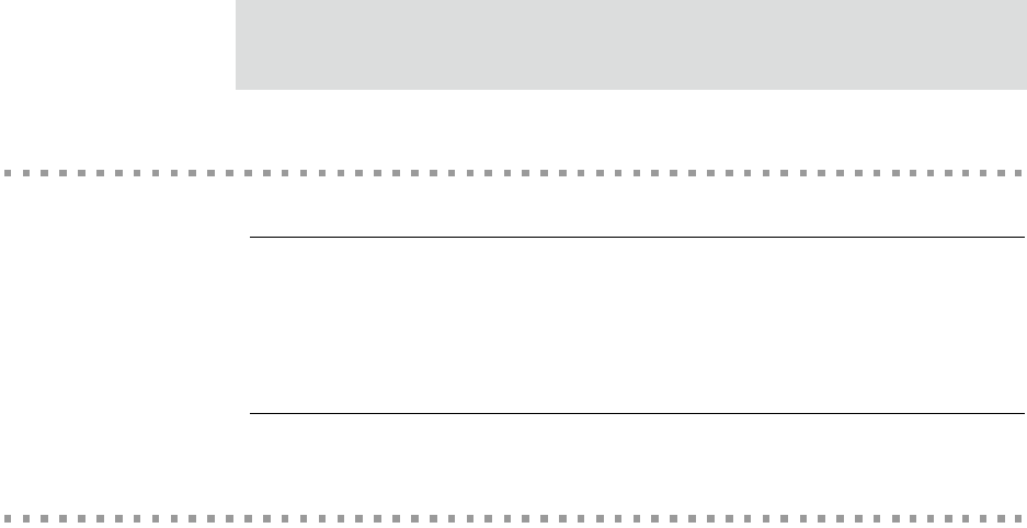
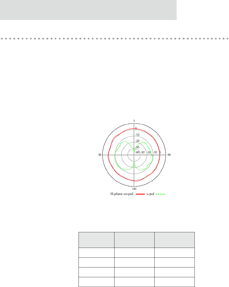
Antenna Strength
The following diagram demonstrates the strength of the signal received by the antenna on
both a horizontal and vertical plane. The diagram shows the magnetic field when the
antenna is in a vertical position. The red line represents the horizontal plane and the dotted
green lined represents the vertical plane. You can see in the illustration that at 90degrees,
the signal strength is (as expected) 0.
Radiation Patterns
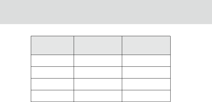
Antenna Details
Antenna
Description Dipole Desktop
Part Number DC-ANT-24DP DC-ANT-24DT
Frequency 2.4~2.5 GHz 2.4~2.5 GHz
Power Output 2 W 1 W
DB Gain 2 dBi 1.8 dBi
29
Specifications
Antenna Restriction in North America
Only antennas of the same type listed on the FCC grant, with equal or lower antenna gain,
may be used with the Digi Connect Wi-SP.
VSWR < or = 2.0 1.92 max
Dimension 10.0x108.5 mm 105 x4.5 mm
Weight 10.5g 11 g
Connector RP-SMA RP-SMA
Antenna
Description Dipole Desktop
Antenna Information
30
Digi Connect SP Hardware Reference
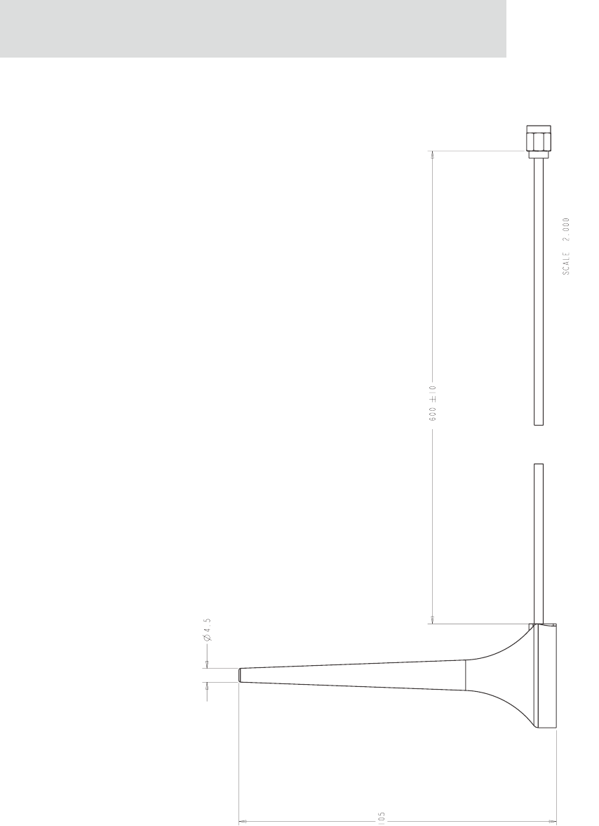
Desktop Antenna Dimensions
Units: mm
31
Specifications
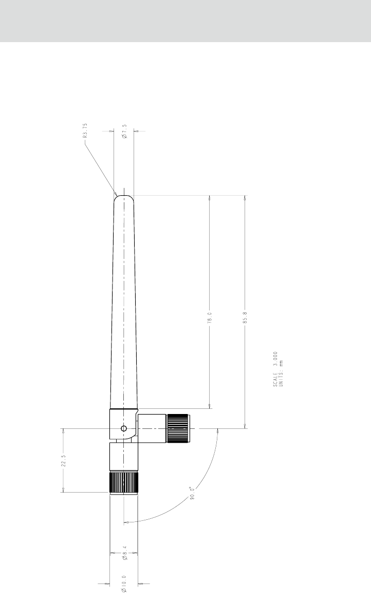
Dipole Antenna Dimensions

RF Exposure Statement
32
Digi Connect SP Hardware Reference
RF Exposure Statement
The Digi Connect Wi-SP device complies with the RF exposure limits for humans as called
out in RSS-102. It is exempt from RF evaluation based on its operating frequency of
2400 MHz, and effective radiated power of 100 milliwatts. This would be less than the 3
watt requirement for a mobile device (>20 cm separation) operating at 2400 MHz.
In order to comply with FCC RF exposure limits, dipole antenna should be located at a
minimum distance of 7.9 inches (20 cm) or more from the body of all persons.

33
Specifications
Overlay Specifications
The following specifications are for the product overlays.
Digi Connect Wi-SP
Digi Connect SP

Overlay Specifications
34
Digi Connect SP Hardware Reference

35
Certifications
APPENDIX B
These products comply with the following standards.
FCC Part 15 Class A
Radio Frequency Interference (RFI) (FCC 15.105(a)
The Digi Connect SP and Digi Connect Wi-SP have been tested and found to comply with
the limits for Class A digital devices pursuant to Part 15 of the FCC Rules. These limits are
designed to provide reasonable protection against harmful interference when the equipment
is operated in a commercial environment. This equipment generates, uses, and can radiate
radio frequency energy, and if not installed and used in accordance with the instruction
manual, may cause harmful interference to radio communications. Operation of this
equipment in a residential area is likely to cause harmful interference in which the user will
be required to correct the interference at his own expense.
Labeling Requirements (FCC 15.19)
This device complies with Part 15 of FCC rules. Operation is subject to the following two
conditions: (1) this device may not cause harmful interference, and (2) this device must
accept any interference received, including interference that may cause undesired
operation.

Industry Canada
36
Digi Connect SP Hardware Reference
Modifications (FCC 15.21)
Changes or modifications to this equipment not expressly approved by Digi may void the
user's authority to operate this equipment.
Cables (FCC 15.27)
Shielded cables must be used to remain within the Class A limitations.
Industry Canada
This digital apparatus does not exceed the Class A limits for radio noise emissions from
digital apparatus set out in the Radio Interference Regulations of the Canadian Department
of Communications.
Le present appareil numerique n'emet pas de bruits radioelectriques depassant les limites
applicables aux appareils numeriques de la class A prescrites dans le Reglement sur le
brouillage radioelectrique edicte par le ministere des Communications du Canada.
37
Certifications
International EMC Standards
The Digi Connect SP and Digi Connect Wi-SP meet the following standards.
Standards Digi Connect SP Digi Connect
Wi-SP
Emissions
AS/NZS 3548
AS/NZS 3548 CISPR 22
FCC Part 15 Subpart C
(FCC ID: MCQ-50M1312)
IC RSS 210 (IC:1846A-50M1312)
ICES-003
EN 55022
EN 61000-3-2
EN 61000-3-3
EN 301 489- 3
EN 300 328
VCCI
Immunity EN 55024
Safety
UL 60950-1
CSA 22.2 No. 60950--1
EN 60950

International EMC Standards
38
Digi Connect SP Hardware Reference

39
Change Log
APPENDIX C
The following changes have been made since the last release of this document.
Revision C
Changed RAM from 8 MB to 16 MB.
Added overlay drawings.
Added desktop antenna information.
Added Japan certification.
.

Revision C
40
Digi Connect SP Hardware Reference
